

HP XMT5160B-622-ST, XMT5160B-622-SC, XMT5160B-622-FP, XMT5160B-622-DN, XMT5160B-155-ST Datasheet
...
622 Mb/s Logic Interface Laser
Transmitter
Preliminary Technical Data
XMT5370-622
Features
• SONET/SDH Compliant to
STM4 I-4, S-4.1
OC12 SR, IR.1
• –40°C to +85°C Operation
• Compact 20 Pin Package
• ECL/PECL Logic Interface
• Multisourced Pinout
Applications
• SONET/SDH Systems
• Fiber to the Home
• Data Communications
Networks
Description
The XMT5370-622 is a high
performance uncooled optical
laser transmitter for CCITT SDH
and ANSI SONET applications. It
is designed with an ECL/PECL
logic interface for 622 MBd
transmission.
The transmitter incorporates
several features which simplify
system design. The
XMT5370-622 may be operated
with either +5 V or –5 V power
supplies. Its standard 10 KH ECL
data interface enables direct
interface with PECL or ECL logic.
The compact transmitter module
contains a pigtailed laser, data
interface, bias and modulation
control circuitry. Thus, no
external components or adjustments are necessary. Finally, a
laser disable input is provided to
shut down the laser for standby
or test purposes.
The XMT5370-622 includes
analog outputs which are
proportional to laser current and
optical power. These may be used
with external circuitry to detect
end-of-life, or over temperature
conditions.
The transmitter is packaged in a
20 pin 0.4" pitch DIP. Contact
your local representative for
more details.
Preliminary Product Disclaimer
This preliminary data sheet is provided to assist you in the evaluation of engineering samples of the product which is under development
and targeted for release during 1997. Until Hewlett-Packard releases this product for general sales, HP reserves the right to alter prices,
specifications, features, capabilities, function, manufacturing release dates, and even general availability of the product at any time.
442
(5/97)
Connection Diagram
Top View
FIBER PIGTAIL
1
2
3
4
5
6
7
8
9
10
LASER BIAS MONITOR (+)
LASER BIAS MONITOR (–)
V
V
TRANSMIT DISABLE
V
V
NC
NC
EE
CC
CC
CC
NC
Pin Descriptions
Pins 1, 3, 10, 20, NC:
These pins should not be connected and should be left open
circuit on the application PCB.
Pin 2, Laser Bias Monitor (+):
See Figure 1.
Pin 4, Laser Bias Monitor (–):
See Figure 1.
Pins 5, 14, VEE:
These pins are connected to
ground in +5 V systems and –5 V
in negative supply systems.
20
19
18
17
16
15
14
13
12
11
NC
LASER BACK FACET MONITOR (+)
V
CC
LASER BACK FACET MONITOR (–)
DATA
DATA
V
EE
CASE GROUND (SEE NOTE BELOW)
V
CC
CASE GROUND (SEE NOTE BELOW)
Pins 6, 8, 9, 12, 18, VCC:
These pins are connected to +5 V
for positive supply systems and
ground for –5.2 V systems.
Pin 7, Transmit Disable:
Pin 7 floats to VEE when open
circuited, enabling the
transmitter. It must be biased
within 3 V of VCC to disable.
Pins 11, 13, Ground:
The XMT5370-622 case is plastic,
therefore pins are not connected.
Pins 15, 16, DATA, DATA:
These are differential ECL inputs.
If open circuited they float to V
BB
(VCC –1.3 V)
Pin 17, Laser Back Facet
Monitor (–):
See Figure 2.
Pin 19, Laser Back Facet
Monitor (+):
See Figure 2.
PIN 2
PIN 4
3 kΩ
3 kΩ
V
CC
LASER
10 Ω
I
BIAS
V
EE
MODULATION
CURRENT
PIN 19
PIN 17
MONITOR
PHOTODIODE
3 kΩ
3 kΩ
V
CC
200 Ω
TO LASER BIAS
CONTROL CIRCUITRY
Figure 1. Laser Bias Monitor Circuitry. Figure 2. Back Facet Monitor Circuitry.
443
XMT5370-622 Block Diagram
DATA
DATA
DISABLE
ECL
INPUT
LASER
MODULATOR
LASER
LASER
BIAS
DRIVER
LASER
BIAS
CONTROL
PHOTODIODE
(REAR FACET
MONITOR)
LASER BIAS
MONITOR
REAR FACET
MONITOR
Functional Description
The ECL input allows operation
from many logic families and
both single-ended or differential
signals. For single-ended
operation both DATA and DATA
are internally tied to a VBB. The
unused input then requires no
connection or biasing.
The disable function disables the
laser bias and modulator. The
switching threshold is VCC –3.2 V.
If this input is not connected the
module is enabled. This input
may be connected to a CMOS HI
or tied to VCC to disable.
444
The module provides the
necessary bias and modulation
control to maintain the extinction
ratio at better than 8.2 dB and
the waveform is compliant with
SONET/SDH Eyemask standard
G.957.
The laser bias control loop
compensates for temperature
induced variations in laser
performance. The bias current
monitor indicates the amount of
dc current supplied to the laser.
(This is approximately the laser
threshold current).
The rear facet monitor is a signal
proportional to the laser output
power. This can be used as part
of a HI/LO light alarm.
In the absence of data the laser
will emit a mean optical power
within the specified limits. The
extinction ratio and duty cycle
distortion are specified assuring a
50% duty cycle at the correct
data rate.
Performance Specifications Absolute Maximum Ratings
Absolute maximum limits mean that no catastrophic damage will occur if the product is subjected to these ratings for short periods, provided
each limiting parameter is in isolation and all other parameters have values within the performance specification. It should not be assumed that
limiting values of more than one parameter can be applied to the product at the same time.
Parameter Minimum Nominal Maximum Units Notes
Supply Voltage - - 7 V Operating Case Temperature
A Model –40 - +85 °C-
B Model 0 - +70 °C-
Storage Temperature –40 - +85 °CFiber Tensile Strength 10 - - N/10s 1
Fiber Bend Radius 32 - - mm Lead Soldering (Temperature/Time) - - +260/10 °C/Sec -
Characteristics
Parameter Minimum Nominal Maximum Units Notes
Center Wavelength 1274 - 1356 nm 2
Spectral Width (RMS) - - 2.5 nm 2
Average Output Power –15 –11 –8 dBm 3
Extinction Ratio 8.2 - - dB Bias Monitor - 0.1 - mA/mV 4
Rear Facet Monitor Output 5 - 50 mV 5
Supply Voltage 4.75 5.0 5.5 V 6
Supply Current - - 130 mA 7
Tx Disable VCC –3.2 - V
CC
Output Waveform SONET/SDH Eyemask Compliant G.957
V-
Notes:
1. In a coaxial direction with fiber feedthrough.
2. Over operating temperature range. A narrower operating temperature range will result in a smaller center wavelength spread.
Contact Hewlett-Packard for details.
3. Other output power options are available. Contact Hewlett-Packard for details.
4. Common mode signal VEE + 3.5 V nominal.
5. Common mode signal VEE + 4.0 V nominal.
6. With VEE connected to -5 V, VCC must be at 0 V. With VCC at +5 V, VEE must be at 0 V.
7. End of life at Tmax.
445
Package Dimensions
L
20 11
C
110
B A
J
H
K
DIM.
A
B
C
D
E
F
∅G
H
J
K
L
ALL DIMENSIONS IN MILLIMETERS
MIN. NOM.
32.9
–
16.0
–
2.6
–
–
2.7
–
–
400
–
–
–
–
–
2.54
0.46
–
–
10.16
–
MAX.
33.2
17.5
16.3
9.27
2.95
–
–
3.2
4.64
–
1220
F∅G
D
E
446

Ordering Information
XMT5370X 622 - XX
Allowable part numbers:
XMT5370A-622-FP
XMT5370A-622-ST
XMT5370A-622-SC
XMT5370B-622-FP
XMT5370B-622-ST
XMT5370B-622-SC
Connector:
FP = FC/PC Polish
ST* = ST
SC = SC
Temperature Option:
A = –40°C to +85°C
B = 0°C to +70°C
Model Name:
XMT5370
Handling Precautions
1. Normal handling precautions
for electrostatic sensitive
devices should be taken.
2. Semiconductor lasers can be
damaged by overloading or by
current surges. Appropriate
transient protection should be
taken.
*ST is a registered trademark of AT&T.
447

155 Mb/s Logic Interface Laser Transmitters for OC3/STM1
Technical Data
XMT5360-155
XMT5160-155
Features
• Full Compliance to SONET
OC3 and SDH STM1
• –40°C to +85°C Operation
• Compact 20 Pin Package
• ECL/PECL Logic Interface
• Multisourced Pinout
• Fully Interchangeable Short
and Long Reach Versions
Applications
• SONET/SDH Systems
• Single Mode ATM
• Fiber to the Home
• Data Communications
Networks
Description
The XMT5360-155 and
XMT5160-155 are high
performance uncooled optical
laser transmitters for CCITT SDH
and ANSI SONET applications.
They are designed with an
ECL/PECL logic interface for
155 Mb/s transmission.
The transmitters incorporate
several features which simplify
system design. They may be
operated with either +5 V or –5 V
power supplies. Standard 10 KH
ECL data interface enables direct
interface with PECL or ECL logic.
The compact transmitter module
contains a pigtailed laser, data
interface, bias and modulation
control circuitry. Thus, no
external components or adjustments are necessary. Finally, a
laser disable input is provided to
shut down the laser for standby
or test purposes.
The two variants of the
transmitter are for intermediate
and long haul applications. The
XMT5360-155 has –10 dBm
mean output power for short and
intermediate reach systems and
the XMT5160-155 has –2.5 dBm
mean output power for long haul
systems. The two versions are
fully interchangeable to allow a
single board design to be configured for short, intermediate,
and long haul applications.
The XMT5360-155 and
XMT5160-155 include analog
outputs which are proportional to
laser current and optical power.
These may be used with external
circuitry to detect end-of-life, or
over temperature conditions. The
transmitters are packaged in a
20 pin 0.4" pitch DIP. An
evaluation board is available for
this product. Contact your local
representative for more details.
448
5965-7334E (2/97)

Connection Diagram
Top View
FIBER PIGTAIL
NC
LASER BIAS MONITOR (+)
NC
LASER BIAS MONITOR (–)
V
EE
V
CC
TRANSMIT DISABLE
V
CC
V
CC
NC
Pin Descriptions
Pins 1, 3, 10, 20, NC:
These pins should not be connected and should be left open
circuit on the application PCB.
Pin 2, Laser Bias Monitor (+):
See Figure 1.
Pin 4, Laser Bias Monitor (–):
See Figure 1.
Pins 5, 14, VEE:
These pins are connected to
ground in +5 V systems and –5 V
in negative supply systems.
1
2
3
4
5
6
7
8
9
10
20
19
18
17
16
15
14
13
12
11
NC
LASER BACK FACET MONITOR (+)
V
CC
LASER BACK FACET MONITOR (–)
DATA
DATA
V
EE
CASE GROUND (SEE NOTE BELOW)
V
CC
CASE GROUND (SEE NOTE BELOW)
Pins 6, 8, 9, 12, 18, VCC:
These pins are connected to +5 V
for positive supply systems and
ground for –5.2 V systems.
Pin 7, Transmit Disable:
Pin 7 floats to VEE when open
circuited, enabling the
transmitter. It must be biased
within 3 V of VCC to disable.
Pins 11, 13, Ground:
These pins connect to the case.
They should always be connected
to circuit ground.
Pins 15, 16, DATA, DATA:
These are differential ECL inputs.
If open circuited they float to V
BB
(VCC –1.3 V).
Pin 17, Laser Back Facet
Monitor (–):
See Figure 2.
Pin 19, Laser Back Facet
Monitor (+):
See Figure 2.
V
PIN 2
PIN 4
3 kΩ
3 kΩ
CC
LASER
10 Ω
I
BIAS
V
EE
MODULATION
CURRENT
PIN 19
PIN 17
MONITOR
PHOTODIODE
3 kΩ
3 kΩ
V
CC
200 Ω
TO LASER BIAS
CONTROL CIRCUITRY
Figure 1. Laser Bias Monitor Circuitry. Figure 2. Back Facet Monitor Circuitry.
449

XMT5360-155 and XMT5160-155 Block Diagram
DATA
DATA
DISABLE
ECL
INPUT
LASER
MODULATOR
LASER
LASER
BIAS
DRIVER
LASER
BIAS
CONTROL
PHOTODIODE
(REAR FACET
MONITOR)
LASER BIAS
MONITOR
REAR FACET
MONITOR
Functional Description
The ECL input allows operation
from many logic families and
both single-ended or differential
signals. For single-ended
operation both DATA and DATA
are internally tied to a VBB. The
unused input then requires no
connection or biasing.
The disable function disables the
laser bias and modulator. The
switching threshold is VCC –3.2 V.
If this input is not connected the
module is enabled. This input
may be connected to a CMOS HI
or tied to VCC to disable.
450
The module provides the
necessary bias and modulation
control to maintain the extinction
ratio at better than 10:1 and the
waveform is compliant with
SONET/SDH Eyemask standard
G.957.
The laser bias control loop
compensates for temperatureinduced variations in laser
performance. The bias current
monitor indicates the amount of
dc current supplied to the laser.
(This is approximately the laser
threshold current).
The rear facet monitor is a signal
proportional to the laser output
power. This can be used as part
of a HI/LO light alarm.
In the absence of data the laser
will emit a mean optical power
within the specified limits. The
extinction ratio and duty cycle
distortion are specified assuring a
50% duty cycle at the correct
data rate.

Performance Specifications Absolute Maximum Ratings
Parameter Minimum Nominal Maximum Units Notes
Supply Voltage - - 7 V Operating Case Temperature
XMT5360A-155 and XMT5160A-155 –40 - +85 °C-
XMT5360B-155 and XMT5160B-155 0 - +70 °C-
Storage Temperature –40 - +85 °C-
Fiber Tensile Strength 10 - - N/10s 1
Fiber Bend Radius 32 - - mm Lead Soldering (Temperature/Time) - - +260/10 °C/Sec -
Characteristics
Parameter Minimum Nominal Maximum Units Notes
Average Output Power XMT5360 –15 –10 –8 dBm 2
XMT5160 –5 –2.5 0 dBm 2
Center Wavelength XMT5360 1261 - 1360 nm 3
XMT5160 1280 - 1335 nm 3
Spectral Width (RMS) - - 4 nm 3
Rise Time (10% - 90%) - - 2 ns Fall Time (10% - 90%) - - 2 ns Extinction Ratio 10 - - dB Bias Monitor - 0.1 - mA/mV 4
Rear Facet Monitor Output 5 - 50 mV 5
Supply Voltage 4.75 5.0 5.5 V 6
Supply Current - 70 130 mA 7
Tx Disable VCC –3.2 - V
CC
Output Waveform SONET/SDH Eyemask Compliant G.957
V-
Notes:
1. In a coaxial direction with fiber feedthrough.
2. Other output power options are available. Contact Hewlett-Packard for details.
3. Over operating temperature range. A narrower operating temperature range will result in a smaller center wavelength spread.
Contact Hewlett-Packard for details.
4. Common mode signal VEE + 3.5 V nominal.
5. Common mode signal VEE + 1.2 V nominal.
6. With VEE connected to -5 V, VCC must be at 0 V. With VCC at +5 V, VEE must be at 0 V.
7. End of life at Tmax.
451

Drawing Dimensions
K
20 11
XMT5160-155
110
B A
J
H
K
20 11
110
BB
F∅G
XMT5360-155
A
C
D
E
C
452
D
J
H
DIM. MAX.
A
B
BB
C
D
E
F
∅G
H
J
K
ALL DIMENSIONS IN MILLIMETERS
MIN. NOM.
32.92
–
–
16.03
–
2.64
–
–
–
–
400
2.54
0.46
10.16
3.3
–
–
–
–
–
–
–
33.12
17.5
24.0
16.23
9.27
2.9
–
–
–
–
1220
F∅G
E

Ordering Information
XMT5X60X 155 - XX
Connector:
FP = FC/PC Polish
Allowable part numbers: ST* = ST
XMT5360A-155-FP SC = SC
XMT5360A-155-ST
XMT5360A-155-SC Data Rate Option:
XMT5360B-155-FP 155 = 155 Mb/s
XMT5360B-155-ST
XMT5360B-155-SC Temperature Option:
XMT5160A-155-FP A = -40°C to +85°C
XMT5160A-155-ST B = 0°C to +70°C
XMT5160A-155-SC
XMT5160B-155-FP Model Name:
XMT5160B-155-ST XMT5360 - Low Power
XMT5160B-155-SC XMT5160 - High Power
Class 1 Laser Product: This product conforms to the
applicable requirements of 21 CFR 1040 at the date of
manufacture.
Date of Manufacture: ____________________________________
Hewlett-Packard Ltd., Whitehouse Road, Ipswich, England
Handling Precautions
1. Normal handling precautions
for electrostatic sensitive
devices should be taken.
2. Semiconductor lasers can be
damaged by overloading or by
current surges. Appropriate
transient protection should be
taken.
*ST is a registered trademark of AT&T.
453

622 Mb/s Logic Interface Laser Transmitter
Technical Data
XMT5160B-622
Features
• SONET/SDH Compliant to
STM4 L-4.1
OC12 LR-1
• 0°C to +70°C Operation
• Compact 20 Pin Package
• ECL/PECL Logic Interface
• Multisourced Pinout
Applications
• SONET/SDH Systems
• Fiber to the Home
• Data Communications
Networks
Description
The XMT5160B-622 laser
transmitter is a high performance
uncooled optical transmitter for
CCITT SDH and ANSI SONET
applications. It is designed with
an ECL/PECL logic interface for
622 Mb/s transmission.
The transmitter incorporates
several features which simplify system design. The
XMT5160B-622 may be operated
with either +5 V or –5 V power
supplies. Its standard 10 KH ECL
data interface enables direct
interface with PECL or ECL logic.
The compact transmitter module
contains a pigtailed laser, data
interface, bias and modulation
control circuitry. Thus, no
external components or adjustments are necessary. Finally, a
laser disable input is provided to
shut down the laser for standby
or test purposes.
The XMT5160B-622 includes
analog outputs which are
proportional to laser current and
optical power. These may be used
with external circuitry to detect
end-of-life, or over temperature
conditions.
The transmitter is packaged in a
20 pin 0.4" pitch DIP. Contact
your local representative for
more details.
454
5965-7489E (3/97)

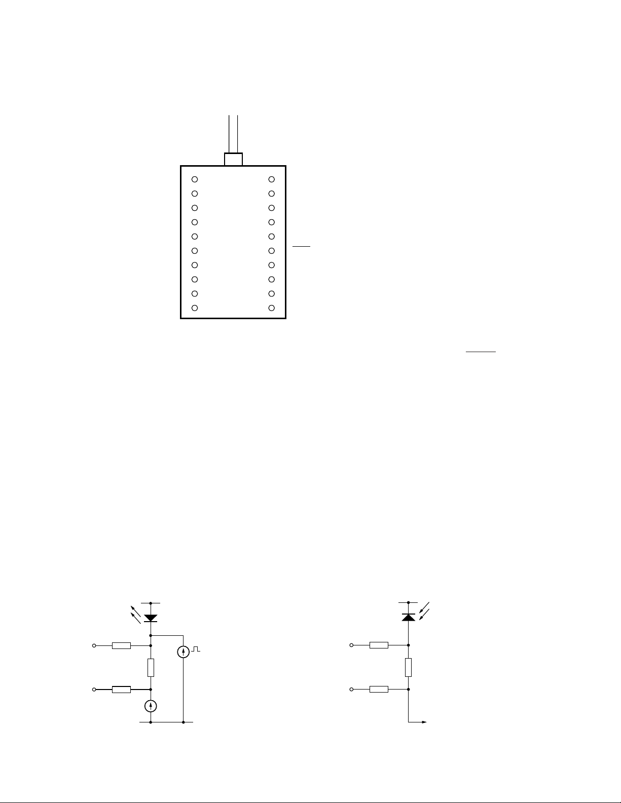
Connection Diagram
Top View
FIBER PIGTAIL
NC
LASER BIAS MONITOR (+)
NC
LASER BIAS MONITOR (–)
V
EE
V
CC
TRANSMIT DISABLE
V
CC
V
CC
NC
Pin Descriptions
Pins 1, 3, 10, 20, NC:
These pins should not be connected and should be left open
circuit on the application PCB.
Pin 2, Laser Bias Monitor (+):
See Figure 1.
Pin 4, Laser Bias Monitor (–):
See Figure 1.
Pins 5, 14, VEE:
These pins are connected to
ground in +5 V systems and –5 V
in negative supply systems.
1
2
3
4
5
6
7
8
9
10
20
19
18
17
16
15
14
13
12
11
NC
LASER BACK FACET MONITOR (+)
V
CC
LASER BACK FACET MONITOR (–)
DATA
DATA
V
EE
CASE GROUND
V
CC
CASE GROUND
Pins 6, 8, 9, 12, 18, VCC:
Connect to +5 V for positive
supply systems and ground for
–5.2 V systems.
Pin 7, Transmit Disable:
Pin 7 floats to VEE when open
circuited, enabling the
transmitter. It must be biased
within 3 V of VCC to disable.
Pins 11, 13, Ground:
These pins should always be
connected to circuit ground.
Pins 15, 16, DATA, DATA:
These are differential ECL inputs.
If open circuited they float to V
BB
(VCC –1.3 V).
Pin 17, Laser Back Facet
Monitor (–):
See Figure 2.
Pin 19, Laser Back Facet
Monitor (+):
See Figure 2.
PIN 2
PIN 4
3 kΩ
3 kΩ
V
CC
LASER
10 Ω
I
BIAS
V
EE
MODULATION
CURRENT
PIN 19
PIN 17
MONITOR
PHOTODIODE
3 kΩ
3 kΩ
V
CC
200 Ω
TO LASER BIAS
CONTROL CIRCUITRY
Figure 1. Laser Bias Monitor Circuitry. Figure 2. Back Facet Monitor Circuitry.
455

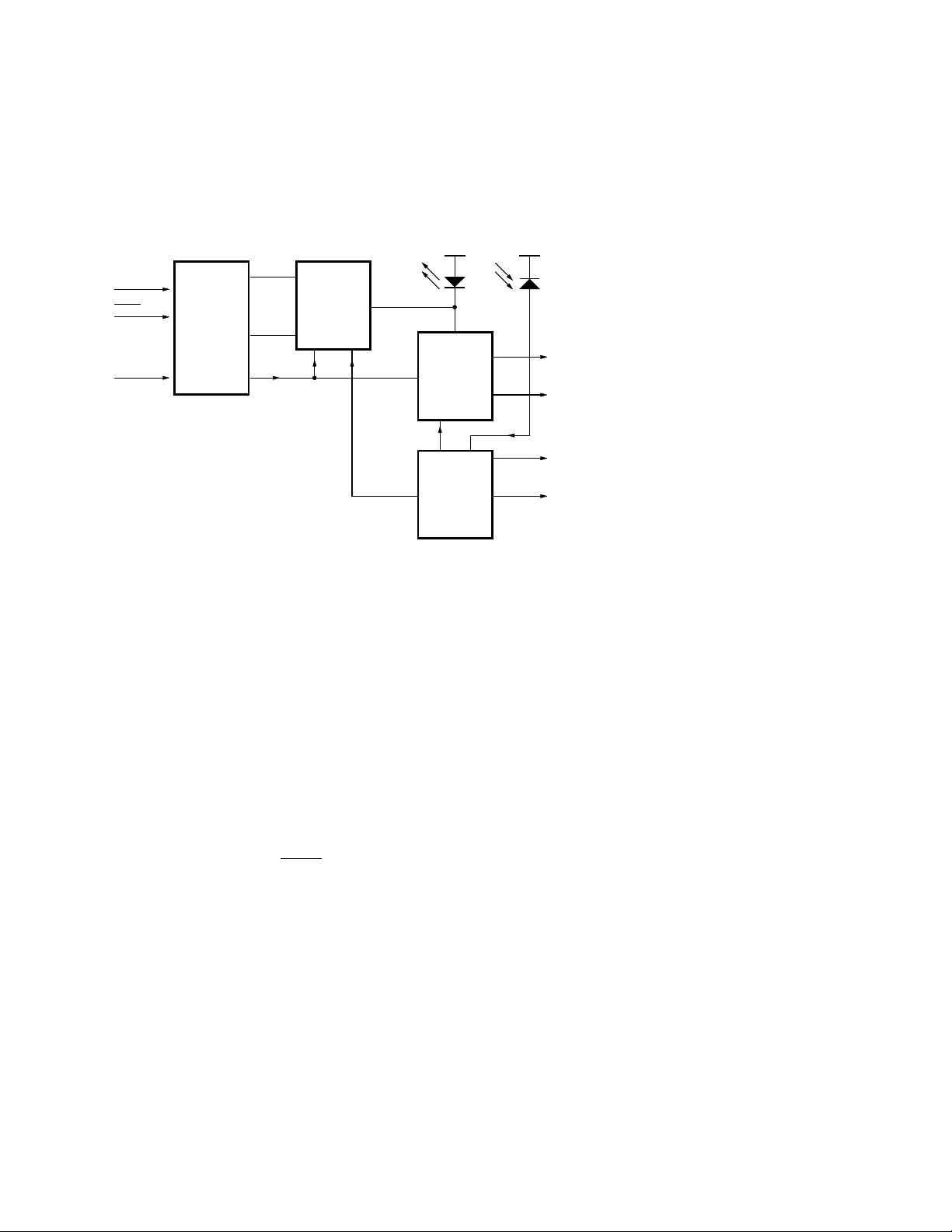
XMT5160B-622 Block Diagram
DATA
DATA
DISABLE
ECL
INPUT
LASER
MODULATOR
LASER
LASER
BIAS
DRIVER
LASER
BIAS
CONTROL
PHOTODIODE
(REAR FACET
MONITOR)
LASER BIAS
MONITOR
REAR FACET
MONITOR
Functional Description
The ECL input allows operation
from many logic families and
both single-ended or differential
signals. For single-ended
operation both DATA and DATA
are internally tied to a VBB. The
unused input then requires no
connection or biasing.
The disable function disables the
laser bias and modulator. The
switching threshold is VCC –3.2 V.
If this input is not connected the
module is enabled. This input
may be connected to a CMOS HI
or tied to VCC to disable.
The module provides the
necessary bias and modulation
control to maintain the extinction
ratio at better than 10 dB and the
waveform is compliant with
SONET/SDH Eyemask standard
G.957.
The laser bias control loop
compensates for temperature
induced variations in laser
performance. The bias current
monitor indicates the amount of
dc current supplied to the laser.
(This is approximately the laser
threshold current).
The rear facet monitor is a signal
proportional to the laser output
power. This can be used as part
of a HI/LO light alarm.
In the absence of data the laser
will emit a mean optical power
within the specified limits. The
extinction ratio and duty cycle
distortion are specified assuring a
50% duty cycle at the correct
data rate.
456

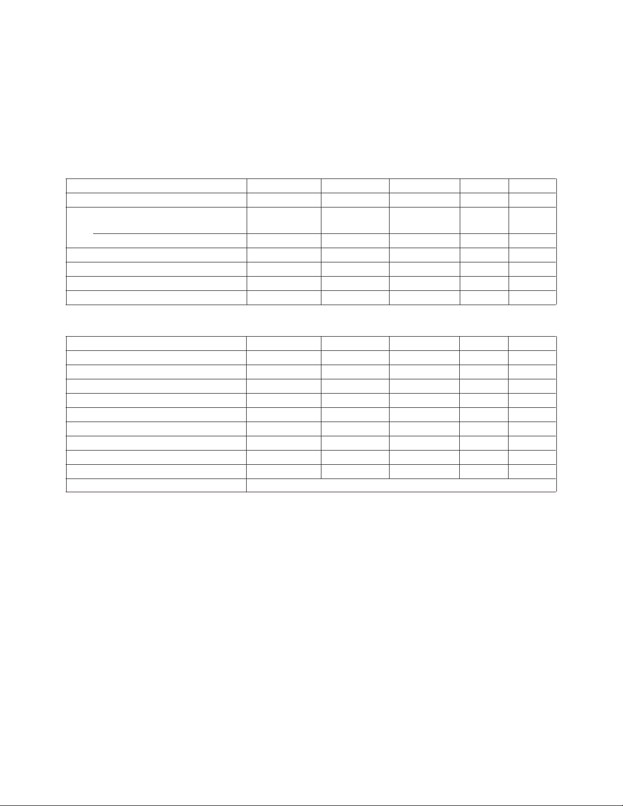
Performance Specifications Absolute Maximum Ratings
Absolute maximum limits mean that no catastrophic damage will occur if the product is subjected to these ratings for short periods, provided
each limiting parameter is in isolation and all other parameters have values within the performance specification. It should not be assumed that
limiting values of more than one parameter can be applied to the product at the same time.
Parameter Minimum Nominal Maximum Units Notes
Supply Voltage - - 7 V Operating Case Temperature
B Model 0 - +70 °C-
Storage Temperature –40 - +85 °CFiber Tensile Strength 10 - - N/10s 1
Fiber Bend Radius 32 - - mm Lead Soldering (Temperature/Time) - - +260/10 °C/Sec -
Characteristics
Parameter Minimum Nominal Maximum Units Notes
Center Wavelength 1296 - 1330 nm Spectral Width (RMS) - - 2.5 nm 2
Average Output Power –3 - 2 dBm 3
Extinction Ratio 10 - - dB Bias Monitor - 0.1 - mA/mV 4
Rear Facet Monitor Output 5 - 50 mV 5
Supply Voltage 4.75 5.0 5.5 V 6
Supply Current - - 150 mA 7
Tx Disable VCC –3.2 - V
CC
Output Waveform SONET/SDH Eyemask Compliant G.957
V-
Notes:
1. In a coaxial direction with fiber feedthrough.
2. Over operating temperature range. A narrower operating temperature range will result in a smaller center wavelength spread.
Contact Hewlett-Packard for details.
3. Other output power options are available. Contact Hewlett-Packard for details.
4. Common mode signal 3.5 V nominal.
5. Common mode signal 4.0 V nominal.
6. With VEE connected to –5 V, VCC must be at 0 V. With VCC at +5 V, VEE must be at 0 V.
7. End of life at Tmax.
457

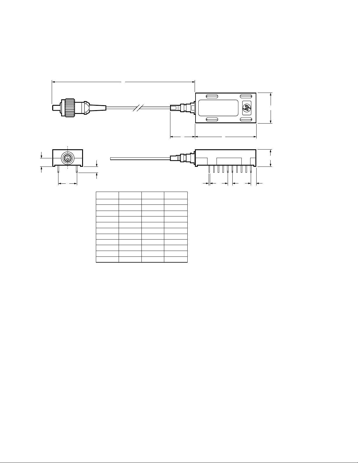
Drawing Dimensions
K
20 11
XMT5160B-622
110
B A
J
H
DIM.
A
B
C
D
E
F
∅G
H
J
K
ALL DIMENSIONS IN MILLIMETERS
MIN. NOM.
32.8
–
15.8
–
2.6
–
–
10.033
3.15
400.00
2.54
0.46
–
–
–
–
–
–
–
–
MAX.
33.2
17.5
16.2
9.27
3.0
–
0.587
10.287
3.65
1220.00
F∅G
C
D
E
458

Ordering Information
XMT5160B - 622 - XX
Allowable part numbers:
XMT5160B-622-FP
XMT5160B-622-ST
XMT5160B-622-DN
XMT5160B-622-SC
Connector:
FP = FC/PC Polish
ST* = ST
DN = DIN
SC = SC
Data Rate Option:
622 = 622 Mb/s
Temperature Option:
B = 0°C to +70°C
Model Name:
XMT5160
Class 1 Laser Product: This product conforms to the applicable
requirements of 21 CFR 1040 at the date of manufacture.
Date of Manufacture: ____________________________________
Hewlett-Packard Ltd., Whitehouse Road, Ipswich, England
Handling Precautions
1. Normal handling precautions
for electrostatic sensitive
devices should be taken.
2. Semiconductor lasers can be
damaged by overloading or by
current surges. Appropriate
transient protection should be
taken.
Laser Warning
*ST is a registered trademark of AT&T.
459
 Loading...