

Page 1

service handbook
hp workstation c-class
Manufacturing Part Number: n/a
Printed in USA October 2001
Edition E1001
Page 2

notice
The information contained in this document is subject to change without notice.
Hewlett-Packard assumes no responsibility for the use or reliability of its software on
equipment that is not furnished by Hewlett-Packard.
This document contains proprietary information that is protected by copyright. All rights
reserved. No part of this document may be photocopied, reproduced or translated to
another language without the prior written consent of Hewlett-Packard Company.
hewlett-packard warranty statement
HP PRODUCT DURATION OF WARRANTY
HP Workstations C-Class one Year
1. HP warrants HP hardware, accessories and supplies against defects in materials and
workmanship for the period specified above. If HP receives notice of such defects during
the warranty period, HP will, at its option, either repair or replace products which
prove to be defective. Replacement products may be either new or like-new.
2. HP warrants that HP software will not fail to execute its programming instructions, for
the period specified above, due to defects in material and workmanship when properly
installed and used. If HP receives notice of such defects during the warranty period, HP
will replace software media which does not execute its programming instructions due to
such defects.
3. HP does not warrant that the operation of HP products will be uninterrupted or error
free. If HP is unable, within a reasonable time, to repair or replace any product to a
condition as warranted, the customer will be entitled to a refund of the purchase price
upon prompt return of the product.
4. HP products may contain remanufactured parts equivalent to new in performance or
may have been subject to incidental use.
5. The warranty period begins on the date of delivery or on the date of installation if
installed by HP. If customer schedules installation or causes installation by HP to be
delayed more than 30 days after delivery, warranty begins on the 31st day from
delivery.
6. Warranty does not apply to defects resulting from (a) improper or inadequate
maintenance or calibration, (b) software, interfacing, parts or supplies not supplied by
HP, (c) unauthorized modification or misuse, (d) operation outside of the published
2
Page 3

environmental specifications for the product, or (e) improper site preparation or
maintenance.
7. TO THE EXTENT ALLOWED BY LOCAL LAW, THE ABOVE WARRANTIES ARE
EXCLUSIVE AND NO OTHER WARRANTY OR CONDITION, WHETHER WRITTEN
OR ORAL, IS EXPRESSED OR IMPLIED AND HP SPECIFICALLYDISCLAIMS ANY
IMPLIED WARRANTIES OR CONDITIONS OF MERCHANTABILITY,
SATISFACTORY QUALITY, AND FITNESS FOR A PARTICULAR PURPOSE.
8. HP will be liable for damage to tangible property per incident up to the greater of
$300,000 or the actual amount paid for the product that is the subject of the claim, and
for damages for bodily injury or death, to the extent that all such damages are
determined by a court of competent jurisdiction to have been directly caused by a
defective HP product.
9. TO THE EXTENT ALLOWED BY LOCAL LAW, THE REMEDIES IN THIS
WARRANTY STATEMENT ARE CUSTOMER’S SOLE AND EXCLUSIVE
REMEDIES. EXCEPT AS INDICATED ABOVE, IN NO EVENT WILL HP OR ITS
SUPPLIERS BE LIABLE FOR LOSS OF DATA OR FOR DIRECT, SPECIAL,
INCIDENTAL, CONSEQUENTIAL (INCLUDING LOST PROFIT OR DATA), OR
OTHER DAMAGE, WHETHER BASED IN CONTRACT, TORT, OR OTHERWISE.
FOR CONSUMER TRANSACTIONS IN AUSTRALIA AND NEW ZEALAND: THE
WARRANTY TERMS CONTAINED IN THIS STATEMENT, EXCEPT TO THE
EXTENT LAWFULLY PERMITTED, DO NOT EXCLUDE, RESTRICT OR MODIFY
AND ARE IN ADDITION TO THE MANDATORY STATUTORY RIGHTS
APPLICABLE TO THE SALE OF THIS PRODUCT TO YOU.
restricted rights legend
Use, duplication, or disclosure by the U.S. Government Department of Defense is subject to
restrictions as set forth in paragraph (b)(3)(ii) of the Rights in Technical Data and
Software clause in DFARS 252.227.7013.
© Copyright 1999 Hewlett-Packard Company. All Rights Reserved.
This document contains proprietary information that is protected by copyright. All rights
are reserved. No part of this document may be photocopied, reproduced or translated to
another language without the prior written consent of Hewlett-Packard Company.
UNIX is a registered trademark in the United States and other countries, licensed
exclusively through X/Open Company Limited.
© Copyright 1980, 1984 AT&T, Inc.
© Copyright 1979, 1980, 1983 The Regents of the University of California.
This software and documentation is based in part on the Fourth Berkeley Software
Distribution under license from the Regents of University of California.
3
Page 4

printing history
New editions of this manual incorporate all material updated since the previous edition.
Update packages may be issued between editions and contain replacement and additional
pages to be merged into the manual by the user.
The manual part number and printing date indicate its current edition. The manual part
number changes when extensive technical changes are incorporated. The printing date
changes when a new edition is printed. (Minor corrections and updates which are
incorporated at reprint do not cause the date to change.)
HP Part Number Printing Date Edition
n/a October 2001 First
4
Page 5

Contents
1. product information
Product Description. . . . . . . . . . . . . . . . . . . . . . . . . . . . . . . . . . . . . . . . . .19
system unit front panel controls. . . . . . . . . . . . . . . . . . . . . . . . . . . . . . . .21
system LCD. . . . . . . . . . . . . . . . . . . . . . . . . . . . . . . . . . . . . . . . . . . . . . .21
system power switch. . . . . . . . . . . . . . . . . . . . . . . . . . . . . . . . . . . . . . . .22
storage device controls and features . . . . . . . . . . . . . . . . . . . . . . . . . . .22
security lock . . . . . . . . . . . . . . . . . . . . . . . . . . . . . . . . . . . . . . . . . . . . . .24
System Unit Rear Panel Connectors . . . . . . . . . . . . . . . . . . . . . . . . . . . .25
audio connectors. . . . . . . . . . . . . . . . . . . . . . . . . . . . . . . . . . . . . . . . . . .26
USB connectors. . . . . . . . . . . . . . . . . . . . . . . . . . . . . . . . . . . . . . . . . . . .27
hp parallel i/o connector. . . . . . . . . . . . . . . . . . . . . . . . . . . . . . . . . . . . .27
802.3 network connectors. . . . . . . . . . . . . . . . . . . . . . . . . . . . . . . . . . . .27
RS-232 serial input/output connectors . . . . . . . . . . . . . . . . . . . . . . . . .28
SCSI connectors . . . . . . . . . . . . . . . . . . . . . . . . . . . . . . . . . . . . . . . . . . .28
TOC button. . . . . . . . . . . . . . . . . . . . . . . . . . . . . . . . . . . . . . . . . . . . . . .29
power cord connector . . . . . . . . . . . . . . . . . . . . . . . . . . . . . . . . . . . . . . .29
security loop . . . . . . . . . . . . . . . . . . . . . . . . . . . . . . . . . . . . . . . . . . . . . .29
monitor information . . . . . . . . . . . . . . . . . . . . . . . . . . . . . . . . . . . . . . . . .31
hp supported USB devices . . . . . . . . . . . . . . . . . . . . . . . . . . . . . . . . . . . .32
USB keyboard. . . . . . . . . . . . . . . . . . . . . . . . . . . . . . . . . . . . . . . . . . . . .32
USB hp scroll mouse . . . . . . . . . . . . . . . . . . . . . . . . . . . . . . . . . . . . . . .32
hp hub for USB devices . . . . . . . . . . . . . . . . . . . . . . . . . . . . . . . . . . . . .32
operating system overview . . . . . . . . . . . . . . . . . . . . . . . . . . . . . . . . . . . .33
memory. . . . . . . . . . . . . . . . . . . . . . . . . . . . . . . . . . . . . . . . . . . . . . . . . . . .34
memory failures . . . . . . . . . . . . . . . . . . . . . . . . . . . . . . . . . . . . . . . . . . .34
2. configuration
chapter overview . . . . . . . . . . . . . . . . . . . . . . . . . . . . . . . . . . . . . . . . . . . .36
workstation configurations . . . . . . . . . . . . . . . . . . . . . . . . . . . . . . . . . . . .37
FRU configurations . . . . . . . . . . . . . . . . . . . . . . . . . . . . . . . . . . . . . . . . . .38
internal storage configurations . . . . . . . . . . . . . . . . . . . . . . . . . . . . . . .38
CD drive (optional) configuration . . . . . . . . . . . . . . . . . . . . . . . . . . . . .42
5
Page 6

Contents
floppy disk drive (optional) configuration . . . . . . . . . . . . . . . . . . . . . . 42
memory . . . . . . . . . . . . . . . . . . . . . . . . . . . . . . . . . . . . . . . . . . . . . . . . . 43
i/o cards . . . . . . . . . . . . . . . . . . . . . . . . . . . . . . . . . . . . . . . . . . . . . . . . . 45
monitor-type selection. . . . . . . . . . . . . . . . . . . . . . . . . . . . . . . . . . . . . . 46
3. troubleshooting
flow diagrams for troubleshooting. . . . . . . . . . . . . . . . . . . . . . . . . . . . . . 49
identifying LCD-indicated conditions . . . . . . . . . . . . . . . . . . . . . . . . . . . 54
LCD fan failures and warnings. . . . . . . . . . . . . . . . . . . . . . . . . . . . . . . . 55
dealing with a boot failure. . . . . . . . . . . . . . . . . . . . . . . . . . . . . . . . . . . . 57
searching for bootable media . . . . . . . . . . . . . . . . . . . . . . . . . . . . . . . . 58
stable storage . . . . . . . . . . . . . . . . . . . . . . . . . . . . . . . . . . . . . . . . . . . . 58
boot command notations. . . . . . . . . . . . . . . . . . . . . . . . . . . . . . . . . . . . 59
supported boot paths. . . . . . . . . . . . . . . . . . . . . . . . . . . . . . . . . . . . . . . 59
ISL environment. . . . . . . . . . . . . . . . . . . . . . . . . . . . . . . . . . . . . . . . . . 59
selftest failures . . . . . . . . . . . . . . . . . . . . . . . . . . . . . . . . . . . . . . . . . . . . 60
chassis codes . . . . . . . . . . . . . . . . . . . . . . . . . . . . . . . . . . . . . . . . . . . . . 61
memory failures . . . . . . . . . . . . . . . . . . . . . . . . . . . . . . . . . . . . . . . . . . 83
running system verification tests . . . . . . . . . . . . . . . . . . . . . . . . . . . . . . 84
running ODE-based diagnostics . . . . . . . . . . . . . . . . . . . . . . . . . . . . . . . 86
4. field replaceable units
exchange and non-exchange part numbers. . . . . . . . . . . . . . . . . . . . . . . 93
FRUs part numbers . . . . . . . . . . . . . . . . . . . . . . . . . . . . . . . . . . . . . . . 94
. . . . . . . . . . . . . . . . . . . . . . . . . . . . . . . . . . . . . . . . . . . . . . . . . . . . . . . . 95
FRU removal and replacement . . . . . . . . . . . . . . . . . . . . . . . . . . . . . . . . 97
system unit front panel. . . . . . . . . . . . . . . . . . . . . . . . . . . . . . . . . . . . . 98
system power supply. . . . . . . . . . . . . . . . . . . . . . . . . . . . . . . . . . . . . . 102
i/o cards . . . . . . . . . . . . . . . . . . . . . . . . . . . . . . . . . . . . . . . . . . . . . . . . 106
system unit fans . . . . . . . . . . . . . . . . . . . . . . . . . . . . . . . . . . . . . . . . . 109
removable media devices . . . . . . . . . . . . . . . . . . . . . . . . . . . . . . . . . . 117
hard disk drive . . . . . . . . . . . . . . . . . . . . . . . . . . . . . . . . . . . . . . . . . . 134
6
Page 7

Contents
DIMM cards . . . . . . . . . . . . . . . . . . . . . . . . . . . . . . . . . . . . . . . . . . . . .141
system unit LCD. . . . . . . . . . . . . . . . . . . . . . . . . . . . . . . . . . . . . . . . . .145
the system board . . . . . . . . . . . . . . . . . . . . . . . . . . . . . . . . . . . . . . . . .147
replacing the battery . . . . . . . . . . . . . . . . . . . . . . . . . . . . . . . . . . . . . .150
5. diagrams
system power . . . . . . . . . . . . . . . . . . . . . . . . . . . . . . . . . . . . . . . . . . . . . .152
system unit block diagram . . . . . . . . . . . . . . . . . . . . . . . . . . . . . . . . . . .153
6. boot console handler
boot console handler features . . . . . . . . . . . . . . . . . . . . . . . . . . . . . . . . .157
accessing the boot console handler . . . . . . . . . . . . . . . . . . . . . . . . . . . . .158
boot console menus . . . . . . . . . . . . . . . . . . . . . . . . . . . . . . . . . . . . . . . . .159
booting the workstation. . . . . . . . . . . . . . . . . . . . . . . . . . . . . . . . . . . . . .164
searching for bootable media . . . . . . . . . . . . . . . . . . . . . . . . . . . . . . . . .166
resetting the workstation . . . . . . . . . . . . . . . . . . . . . . . . . . . . . . . . . . . .167
displaying and setting paths. . . . . . . . . . . . . . . . . . . . . . . . . . . . . . . . . .168
displaying and setting the monitor type. . . . . . . . . . . . . . . . . . . . . . . . .170
the monitor command . . . . . . . . . . . . . . . . . . . . . . . . . . . . . . . . . . . . .170
displaying the current monitor configuration. . . . . . . . . . . . . . . . . . .171
setting the monitor type. . . . . . . . . . . . . . . . . . . . . . . . . . . . . . . . . . . .172
setting the monitor type at power on . . . . . . . . . . . . . . . . . . . . . . . . .173
troubleshooting monitor problems. . . . . . . . . . . . . . . . . . . . . . . . . . . .174
displaying the current memory configuration . . . . . . . . . . . . . . . . . . . .175
memory information sample . . . . . . . . . . . . . . . . . . . . . . . . . . . . . . . .176
displaying the status of the i/o slots . . . . . . . . . . . . . . . . . . . . . . . . . . . .177
setting the auto boot and auto search flags . . . . . . . . . . . . . . . . . . . . . .178
displaying and setting the security mode. . . . . . . . . . . . . . . . . . . . . . . .179
displaying and setting fastboot mode. . . . . . . . . . . . . . . . . . . . . . . . . . .180
displaying and setting the LAN station address . . . . . . . . . . . . . . . . . .181
displaying system information . . . . . . . . . . . . . . . . . . . . . . . . . . . . . . . .182
displaying pim information. . . . . . . . . . . . . . . . . . . . . . . . . . . . . . . . . . .183
7
Page 8

Contents
stable storage . . . . . . . . . . . . . . . . . . . . . . . . . . . . . . . . . . . . . . . . . . . . . 184
ISL environment . . . . . . . . . . . . . . . . . . . . . . . . . . . . . . . . . . . . . . . . . . 185
invoking ISL from the boot console handler . . . . . . . . . . . . . . . . . . . 185
ISL user commands. . . . . . . . . . . . . . . . . . . . . . . . . . . . . . . . . . . . . . . 185
obtaining and updating system firmware. . . . . . . . . . . . . . . . . . . . . . . 187
to install the firmware update . . . . . . . . . . . . . . . . . . . . . . . . . . . . . . 187
firmware update example. . . . . . . . . . . . . . . . . . . . . . . . . . . . . . . . . . 188
A. product specifications
regulatory and safety statements . . . . . . . . . . . . . . . . . . . . . . . . . . . . . 192
emissions regulations . . . . . . . . . . . . . . . . . . . . . . . . . . . . . . . . . . . . . 194
special video configuration statement . . . . . . . . . . . . . . . . . . . . . . . . 194
emissions regulations compliance . . . . . . . . . . . . . . . . . . . . . . . . . . . 195
acoustics. . . . . . . . . . . . . . . . . . . . . . . . . . . . . . . . . . . . . . . . . . . . . . . . 196
laser safety statement (U.S.A.). . . . . . . . . . . . . . . . . . . . . . . . . . . . . . 196
LEDs . . . . . . . . . . . . . . . . . . . . . . . . . . . . . . . . . . . . . . . . . . . . . . . . . . 196
electrostatic discharge (ESD) precautions. . . . . . . . . . . . . . . . . . . . . 196
warnings . . . . . . . . . . . . . . . . . . . . . . . . . . . . . . . . . . . . . . . . . . . . . . . 197
environmental specifications. . . . . . . . . . . . . . . . . . . . . . . . . . . . . . . . . 198
acoustics . . . . . . . . . . . . . . . . . . . . . . . . . . . . . . . . . . . . . . . . . . . . . . . 198
altitude . . . . . . . . . . . . . . . . . . . . . . . . . . . . . . . . . . . . . . . . . . . . . . . . 198
DC magnetic field interference. . . . . . . . . . . . . . . . . . . . . . . . . . . . . . 198
electromagnetic compatibility (EMC) . . . . . . . . . . . . . . . . . . . . . . . . 198
temperature. . . . . . . . . . . . . . . . . . . . . . . . . . . . . . . . . . . . . . . . . . . . . 198
humidity (non-condensing). . . . . . . . . . . . . . . . . . . . . . . . . . . . . . . . . 198
leakage current . . . . . . . . . . . . . . . . . . . . . . . . . . . . . . . . . . . . . . . . . . 198
shock . . . . . . . . . . . . . . . . . . . . . . . . . . . . . . . . . . . . . . . . . . . . . . . . . . 198
vibration . . . . . . . . . . . . . . . . . . . . . . . . . . . . . . . . . . . . . . . . . . . . . . . 199
electrical specifications . . . . . . . . . . . . . . . . . . . . . . . . . . . . . . . . . . . . . 200
input power . . . . . . . . . . . . . . . . . . . . . . . . . . . . . . . . . . . . . . . . 200
line power . . . . . . . . . . . . . . . . . . . . . . . . . . . . . . . . . . . . . . . . . . . . . . 200
8
Page 9

Contents
B. SCSI connections
SCSI Bus Differences . . . . . . . . . . . . . . . . . . . . . . . . . . . . . . . . . . . . . . .203
SCSI restrictions . . . . . . . . . . . . . . . . . . . . . . . . . . . . . . . . . . . . . . . . . . .204
cables. . . . . . . . . . . . . . . . . . . . . . . . . . . . . . . . . . . . . . . . . . . . . . . . . . .204
terminators. . . . . . . . . . . . . . . . . . . . . . . . . . . . . . . . . . . . . . . . . . . . . .206
number of devices per SCSI bus . . . . . . . . . . . . . . . . . . . . . . . . . . . . .206
considerations for selecting SCSI devices. . . . . . . . . . . . . . . . . . . . . .206
SCSI bus length constraints . . . . . . . . . . . . . . . . . . . . . . . . . . . . . . . . . .208
Ultra narrow single-ended SCSI bus length. . . . . . . . . . . . . . . . . . . .208
Ultra2 wide low-voltage differential SCSI bus length . . . . . . . . . . . .208
assigning SCSI device IDs. . . . . . . . . . . . . . . . . . . . . . . . . . . . . . . . . . . .210
assigning Ultra narrow single-ended SCSI device IDs . . . . . . . . . . .211
assigning Ultra2 wide low-voltage differential SCSI device IDs. . . .211
connecting to the SCSI ports. . . . . . . . . . . . . . . . . . . . . . . . . . . . . . . . . .212
system SCSI port connection. . . . . . . . . . . . . . . . . . . . . . . . . . . . . . . .212
C. related documentation
. . . . . . . . . . . . . . . . . . . . . . . . . . . . . . . . . . . . . . . . . . . . . . . . . . . . . . . . .216
installation manual . . . . . . . . . . . . . . . . . . . . . . . . . . . . . . . . . . . . . . .216
service manuals . . . . . . . . . . . . . . . . . . . . . . . . . . . . . . . . . . . . . . . . . .216
reference manuals . . . . . . . . . . . . . . . . . . . . . . . . . . . . . . . . . . . . . . . .216
Glossary
9
Page 10

Contents
10
Page 11

Figures
Figure 1-1. System Unit Front Panel Controls . . . . . . . . . . . . . . . . . . . . . . . . . . . . . . . . . . 21
Figure 1-2. LCD Symbols . . . . . . . . . . . . . . . . . . . . . . . . . . . . . . . . . . . . . . . . . . . . . . . . . . . 22
Figure 1-3. CD Drive. . . . . . . . . . . . . . . . . . . . . . . . . . . . . . . . . . . . . . . . . . . . . . . . . . . . . . .23
Figure 1-4. Floppy Drive Controls and Features. . . . . . . . . . . . . . . . . . . . . . . . . . . . . . . . . 24
Figure 1-5. System Unit Rear Panel Connectors. . . . . . . . . . . . . . . . . . . . . . . . . . . . . . . . . 25
Figure 1-6. Audio Connectors . . . . . . . . . . . . . . . . . . . . . . . . . . . . . . . . . . . . . . . . . . . . . . . . 26
Figure 1-7. Security Loop Operation . . . . . . . . . . . . . . . . . . . . . . . . . . . . . . . . . . . . . . . . . . 30
Figure 2-1. Hard Drive, 9Gbyte/18Gbyte Ultra2 Low Voltage Differential. . . . . . . . . . . . 39
Figure 2-2. CD Drive Jumper Setting (Rear View) . . . . . . . . . . . . . . . . . . . . . . . . . . . . . . . 42
Figure 2-3. Memory Connectors . . . . . . . . . . . . . . . . . . . . . . . . . . . . . . . . . . . . . . . . . . . . . . 43
Figure 2-4. PCI Card Slot Numbering and Capabilities. . . . . . . . . . . . . . . . . . . . . . . . . . . 45
Figure 3-1. Power On LCD, Troubleshooting Flow . . . . . . . . . . . . . . . . . . . . . . . . . . . . . . . 50
Figure 3-2. Console Troubleshooting Messages. . . . . . . . . . . . . . . . . . . . . . . . . . . . . . . . . . 51
Figure 3-3. Bootable Device Troubleshooting . . . . . . . . . . . . . . . . . . . . . . . . . . . . . . . . . . . 52
Figure 3-4. Troubleshooting HP-UX Boot . . . . . . . . . . . . . . . . . . . . . . . . . . . . . . . . . . . . . . 53
Figure 3-5. Fan Locations . . . . . . . . . . . . . . . . . . . . . . . . . . . . . . . . . . . . . . . . . . . . . . . . . . . 56
Figure 4-1. HP Workstation C-Class Main Components. . . . . . . . . . . . . . . . . . . . . . . . . . . 89
Figure 4-2. CD Drive Bracket Assembly . . . . . . . . . . . . . . . . . . . . . . . . . . . . . . . . . . . . . . . 90
Figure 4-3. Floppy Drive Bracket Assembly . . . . . . . . . . . . . . . . . . . . . . . . . . . . . . . . . . . . 91
Figure 4-4. Hard Disk Drive Bracket Assembly . . . . . . . . . . . . . . . . . . . . . . . . . . . . . . . . . 92
Figure 4-5. Opening the Front Bezel . . . . . . . . . . . . . . . . . . . . . . . . . . . . . . . . . . . . . . . . . . 98
Figure 4-6. Opening the Left Side Panel of the System Unit . . . . . . . . . . . . . . . . . . . . . . 100
Figure 4-7. Unscrewing the Power Supply Captive Screws . . . . . . . . . . . . . . . . . . . . . . . 102
Figure 4-8. Propping Up the Power Supply. . . . . . . . . . . . . . . . . . . . . . . . . . . . . . . . . . . . 103
Figure 4-9. Disconnecting the Power Supply Cables. . . . . . . . . . . . . . . . . . . . . . . . . . . . . 104
Figure 4-10. Removing the Power Supply . . . . . . . . . . . . . . . . . . . . . . . . . . . . . . . . . . . . . 105
Figure 4-11. PCI Card Slot Numbering and Capabilities. . . . . . . . . . . . . . . . . . . . . . . . . 106
Figure 4-12. I/O Slot Numbering . . . . . . . . . . . . . . . . . . . . . . . . . . . . . . . . . . . . . . . . . . . . 106
Figure 4-13. Removing the I/O Card Retainer. . . . . . . . . . . . . . . . . . . . . . . . . . . . . . . . . . 107
Figure 4-14. Removing the I/O Card . . . . . . . . . . . . . . . . . . . . . . . . . . . . . . . . . . . . . . . . . 107
Figure 4-15. Fan Cooling Areas for the System Unit . . . . . . . . . . . . . . . . . . . . . . . . . . . . 109
Figure 4-16. Removing the Fan from the Hard Disk Drive Chassis. . . . . . . . . . . . . . . . . 111
Figure 4-17. Removing the Fan Rivets. . . . . . . . . . . . . . . . . . . . . . . . . . . . . . . . . . . . . . . . 112
Figure 4-18. Removing CPU Area Fans . . . . . . . . . . . . . . . . . . . . . . . . . . . . . . . . . . . . . . . 113
Figure 4-19. Removing the System Unit Air Divider . . . . . . . . . . . . . . . . . . . . . . . . . . . . 114
Figure 4-20. Removing the Fan and Speaker from the I/O Area . . . . . . . . . . . . . . . . . . . 115
Figure 4-21. Removing the Fan and Speaker from the Bracket. . . . . . . . . . . . . . . . . . . . 115
Figure 4-22. Removing the CD Drive Rear Cover . . . . . . . . . . . . . . . . . . . . . . . . . . . . . . . 118
Figure 4-23. Front of System Unit with the Front Panel Removed . . . . . . . . . . . . . . . . . 118
11
Page 12

Figures
Figure 4-24. Removing the CD Drive Bracket and Blank . . . . . . . . . . . . . . . . . . . . . . . . .119
Figure 4-25. Installing the CD Drive . . . . . . . . . . . . . . . . . . . . . . . . . . . . . . . . . . . . . . . . .120
Figure 4-26. Tightening the Bracket Screws . . . . . . . . . . . . . . . . . . . . . . . . . . . . . . . . . . .120
Figure 4-27. Plugging in the ATAPI and Power Cables. . . . . . . . . . . . . . . . . . . . . . . . . . .121
Figure 4-28. Replacing the Rear EMI CD Drive Cover . . . . . . . . . . . . . . . . . . . . . . . . . . .121
Figure 4-29. Removing the CD Drive’s Rear Cover . . . . . . . . . . . . . . . . . . . . . . . . . . . . . .122
Figure 4-30. Front of the System Unit with the Front Panel Removed . . . . . . . . . . . . . .122
Figure 4-31. Removing the CD Drive . . . . . . . . . . . . . . . . . . . . . . . . . . . . . . . . . . . . . . . . .123
Figure 4-32. Installing the CD Drive Blank . . . . . . . . . . . . . . . . . . . . . . . . . . . . . . . . . . . .124
Figure 4-33. Tightening the Bracket Screws . . . . . . . . . . . . . . . . . . . . . . . . . . . . . . . . . . .124
Figure 4-34. Replacing the CD Drive Rear Cover. . . . . . . . . . . . . . . . . . . . . . . . . . . . . . . .125
Figure 4-35. Removing the Floppy Disk’s Rear Cover . . . . . . . . . . . . . . . . . . . . . . . . . . . .126
Figure 4-36. Front of Workstation with the Front Panel Removed. . . . . . . . . . . . . . . . . .126
Figure 4-37. Removing the Floppy Disk Bracket and Blank. . . . . . . . . . . . . . . . . . . . . . .127
Figure 4-38. Installing the Floppy Disk Drive . . . . . . . . . . . . . . . . . . . . . . . . . . . . . . . . . .128
Figure 4-39. Tightening the Bracket Screws . . . . . . . . . . . . . . . . . . . . . . . . . . . . . . . . . . .128
Figure 4-40. Plugging in the Data and Power Cables . . . . . . . . . . . . . . . . . . . . . . . . . . . .129
Figure 4-41. Replacing the Rear Floppy Cover. . . . . . . . . . . . . . . . . . . . . . . . . . . . . . . . . .129
Figure 4-42. Removing the Floppy Disk’s Rear Cover . . . . . . . . . . . . . . . . . . . . . . . . . . . .130
Figure 4-43. Front of Workstation with the Front Panel Removed. . . . . . . . . . . . . . . . . .130
Figure 4-44. Removing the Floppy Disk Drive . . . . . . . . . . . . . . . . . . . . . . . . . . . . . . . . . .131
Figure 4-45. Installing the Floppy Disk Blank and Bracket . . . . . . . . . . . . . . . . . . . . . . .132
Figure 4-46. Tightening the Bracket Screws . . . . . . . . . . . . . . . . . . . . . . . . . . . . . . . . . . .132
Figure 4-47. Replacing the Rear Floppy Cover. . . . . . . . . . . . . . . . . . . . . . . . . . . . . . . . . .133
Figure 4-48. The Hard Drive Slots . . . . . . . . . . . . . . . . . . . . . . . . . . . . . . . . . . . . . . . . . . .135
Figure 4-49. Removing the Hard Drive Bracket. . . . . . . . . . . . . . . . . . . . . . . . . . . . . . . . .136
Figure 4-50. Inserting the Hard Disk Drive . . . . . . . . . . . . . . . . . . . . . . . . . . . . . . . . . . . .137
Figure 4-51. The Hard Drive Slots . . . . . . . . . . . . . . . . . . . . . . . . . . . . . . . . . . . . . . . . . . .138
Figure 4-52. Removing the Hard Disk Drive . . . . . . . . . . . . . . . . . . . . . . . . . . . . . . . . . . .138
Figure 4-53. Removing the Hard Disk Drive from the Bracket. . . . . . . . . . . . . . . . . . . . .139
Figure 4-54. Replacing the Hard Disk Drive Bracket . . . . . . . . . . . . . . . . . . . . . . . . . . . .140
Figure 4-55. Propping Up the Power Supply . . . . . . . . . . . . . . . . . . . . . . . . . . . . . . . . . . .141
Figure 4-56. DIMM Card Slot Numbers and Loading Sequence. . . . . . . . . . . . . . . . . . . .142
Figure 4-57. Installing Memory Cards . . . . . . . . . . . . . . . . . . . . . . . . . . . . . . . . . . . . . . . .143
Figure 4-58. Propping Up the Power Supply . . . . . . . . . . . . . . . . . . . . . . . . . . . . . . . . . . .144
Figure 4-59. Removing Memory Cards . . . . . . . . . . . . . . . . . . . . . . . . . . . . . . . . . . . . . . . .144
Figure 4-60. Removing the System Unit LCD . . . . . . . . . . . . . . . . . . . . . . . . . . . . . . . . . .145
Figure 4-61. Removing the System Board . . . . . . . . . . . . . . . . . . . . . . . . . . . . . . . . . . . . .148
Figure 4-62. Installing the System Board. . . . . . . . . . . . . . . . . . . . . . . . . . . . . . . . . . . . . .149
12
Page 13

Figures
Figure 5-1. Power Distribution Diagram. . . . . . . . . . . . . . . . . . . . . . . . . . . . . . . . . . . . . . 152
Figure 5-2 System Unit Functional Block Diagram . . . . . . . . . . . . . . . . . . . . . . . . . . . . . 153
Figure A-1. VCCI Class B ITE (Japan) . . . . . . . . . . . . . . . . . . . . . . . . . . . . . . . . . . . . . . . 195
Figure A-2. RRL Class A EMI (Korea). . . . . . . . . . . . . . . . . . . . . . . . . . . . . . . . . . . . . . . . 195
Figure A-3. EMI Class A (Taiwan) . . . . . . . . . . . . . . . . . . . . . . . . . . . . . . . . . . . . . . . . . . . 195
Figure B-1. SCSI Ports . . . . . . . . . . . . . . . . . . . . . . . . . . . . . . . . . . . . . . . . . . . . . . . . . . . . 212
13
Page 14

Figures
14
Page 15

Tables
Table 1-1. CD Drive Controls . . . . . . . . . . . . . . . . . . . . . . . . . . . . . . . . . . . . . . . . . . . . . . . . 23
Table 1-2. Floppy Drive Controls and Features. . . . . . . . . . . . . . . . . . . . . . . . . . . . . . . . . . 24
Table 1-3. Audio Electrical Specifications . . . . . . . . . . . . . . . . . . . . . . . . . . . . . . . . . . . . . . 27
Table 1-4. Serial I/O Pins . . . . . . . . . . . . . . . . . . . . . . . . . . . . . . . . . . . . . . . . . . . . . . . . . . .28
Table 2-1. Default Device IDs TABLE . . . . . . . . . . . . . . . . . . . . . . . . . . . . . . . . . . . . . . . . . 38
Table 3-1. Fan Numbers and Corresponding Name . . . . . . . . . . . . . . . . . . . . . . . . . . . . . . 55
Table 3-2. Chassis Codes for th HP Workstation C-Class. . . . . . . . . . . . . . . . . . . . . . . . . . 61
Table 4-1. Exchange Parts FRU List . . . . . . . . . . . . . . . . . . . . . . . . . . . . . . . . . . . . . . . . . . 94
Table 4-2. Non-exchange Parts FRU List. . . . . . . . . . . . . . . . . . . . . . . . . . . . . . . . . . . . . . . 95
Table 6-1. System Paths . . . . . . . . . . . . . . . . . . . . . . . . . . . . . . . . . . . . . . . . . . . . . . . . . . . 168
Table 6-2. Mnemonic Style Notation . . . . . . . . . . . . . . . . . . . . . . . . . . . . . . . . . . . . . . . . . 168
Table B-1. SCSI Bus Differences . . . . . . . . . . . . . . . . . . . . . . . . . . . . . . . . . . . . . . . . . . . . 203
Table B-2. Ultra Narrow Single-Ended SCSI Cables . . . . . . . . . . . . . . . . . . . . . . . . . . . . 204
Table B-3. Ultra2 Wide Low-Voltage Differential SCSI Cables . . . . . . . . . . . . . . . . . . . . 205
15
Page 16

Tables
16
Page 17

1 product information
This chapter introduces the HP workstation c-class, including its controls and indicators.
This information is provided to help familiarize you with the main features and
components of this workstation.
17
Page 18

product information
Included in this chapter are the following topics:
• Product description
• System unit front panel controls
• System unit rear panel connectors
• Monitor information
• Keyboard and Mouse information
• Operating System Overview
18 Chapter1
Page 19

Product Description
The HP workstation c-class contains the following key features:
• Processor:
— One PA-RISC processor
• Operating System:
HP-UX operating system
• User Interface:
HP CDE graphical user interface
• Monitors:
— 19-inch, 1280×1024 and 1600×1200 color, 75Hz
— 21-inch 1280×1024 (stereo capability) and 1600×1200 color, 75Hz
• Optional Graphics:
product information
Product Description
HP V
ISUALIZE-EG, VISUALIZE fx2 Pro and VISUALIZE fx4 Pro
• Main Memory:
— 128MByte and 256MByte DIMMs for the HP workstation c-class
— Eight memory slots are available per each HP workstation c-class
• Internal Storage Devices:
– Wide Ultra2 Low-Voltage Differential SCSI – up to two:
9.0 GB Hard Disk Drive
18.0 GB Hard Disk Drive
– Removable Media (one of each maximum)
CD-ROM Drive
Floppy Disk Drive
• Standard Network:
– RJ45, Twisted Pair 10 BaseT/100 BaseT
• Standard I/O Ports:
— Ultra2 Wide Low-Voltage Differential (LVD) SCSI, one
— Ultra Narrow Single-Ended (NSE) SCSI, one
— Parallel port (IEEE 1284), one
— Universal Serial Bus (USB) ports, two
— Serial Interface ports (RS-232C), two
— Audio ports (Line-in, Line-out, headset, and microphone-in)
Chapter 1 19
Page 20

product information
Product Description
• Optional I/O:
Six PCI slots are available for the HP workstation c-class.
– 1 PCI 4X:64 bit, 66 MHz, primary graphics (full size, 3.3V)
– 2 PCI 1X:32 bit, 33 MHz, (half size, 5V)
– 3 PCI 2X:64 bit, 33 MHz, (full size, 5V)
• Keyboard:
– Universal Serial Bus (USB) keyboard, one
• Mouse:
– Universal Serial Bus (USB) mouse, one
20 Chapter1
Page 21

system unit front panel controls
system unit front panel controls
Figure 1-1 shows the location of the system unit front panel controls.
Figure 1-1. System Unit Front Panel Controls
System
LCD Display
System
Power Switch
Storage
Devices
product information
Security
Lock
system LCD
The Liquid Crystal Display (LCD) is located on the left side of the front panel. The LCD
displays 2-lines of information, with up to 16-characters per line. It displays messages
about the state of the system, including error codes. Figure 1-2. on page 22, describes the
symbols representing the different system activities. For information about error codes,
refer to Chapter 3 , “troubleshooting,” on page 47.
Chapter 1 21
Page 22

product information
system unit front panel controls
Figure 1-2. LCD Symbols
system power switch
Use the Power switch to power the system unit on and off. When you use the soft power
down procedure, the HP workstations’ c-class hardware is designed to produce the proper
diagnostic and self test messages, and broadcasts a warning message to remote terminals
that it is about to shutdown. The operating system executes an automatic shutdown -q
command. Turning the power switch back on again automatically boots up the HP-UX
operating system if the system has been configured to auto boot. For information on
setting auto boot, refer to the section “setting the auto boot and auto search flags” on
page 178.
storage device controls and features
This workstation allows either or both of the following internal storage devices: CD drive
or floppy disk drive. The following sections describe the controls and features of these
devices.
NOTE
Figure 1-3. shows the operating controls and features of the CD drive, and Table 1-1.
describes those controls and features.
You cannot have two internal storage devices of the same type. For example,
you cannot have two floppy disk drives, and you cannot have two CDROMs.
22 Chapter1
Page 23

Figure 1-3. CD Drive
Disk Tray
product information
system unit front panel controls
Emergency Eject
Eject ButtonBusy Indicator
Table 1-1. CD Drive Controls
Control/Feature Purpose
Eject Button Press to open the Disc Tray and insertor remove a disc. When
the drive is in use, press the eject button for more than one
second to open the Disc Tray. Press to close the tray.
Emergency Eject If the workstation does no have power, you can insert the end
of a paper clip into this small hole to open the Disc Tray.
Disk Tray The Disk Tray holds the CD. This style of CD drive does not
use a disk caddy.
Busy Indicator Lights during a data access operation and blinks during a
data transfer. The indicator blinks initially and then stays lit
when there is one of the following.
• A defective disc
• A disc insertion error (for example, an upside down disc)
• No disc present
NOTE
The audio features of the CD drive are supported through applications only.
One such application is xmcd. The xmcd utility is not a part of HP-UX, you
will need to download it off the web using your web browser and this URL:
http://metalab.unc.edu/tkan/xmcd
Chapter 1 23
Page 24

product information
system unit front panel controls
The optional floppy disk drive (Product Number A5009A) is a 3.5-inch form factor device
with a PC/AT interface. It connects to the workstation via a 34-pin PC/AT ribbon cable and
a 4-pin power cable. The floppy disk drive has up to 1.44 MByte capacity depending on the
media and format used.
Figure 1-4. shows the operating controls and features of the floppy drive, and Table 1-2.
describes those controls and features.
Figure 1-4. Floppy Drive Controls and Features
Eject ButtonBusy Indicator
Table 1-2. Floppy Drive Controls and Features
Control/Feature Purpose
Floppy Drive Eject Button Push the eject button to remove floppy
diskettes from the drive.
Floppy Drive Activity LED
The floppy drive LED flashes to
indicate the drive is in use.
security lock
Access to the mass storage devices is controlled by a security lock on the front panel.
Locking the workstation front panel minimizes potential unauthorized user access.
To prevent access to internal components requires the use of the security loop on the rear
panel of the workstation. See “unit rear panel controls.”
24 Chapter1
Page 25

product information
System Unit Rear Panel Connectors
System Unit Rear Panel Connectors
This section describes the following connectors on the system unit’s rear panel:
• Two serial ports (RS-232)
• Two Universal Serial Bus ports (USB)
• LAN connector, 10 BaseT/100 BaseT
• HP parallel IEEE 1284 (printer) connector
• Audio connectors (PCI based, line in, line out, headset, and microphone in)
• Ultra2 Wide LVD (Low Voltage Differential) SCSI
• Ultra Narrow Single-Ended (NSE) SCSI
• TOC (transfer of control) button
• AC power cord connector
• Security loop
NOTE
To maintain FCC/EMI compliance, verify that all cables are fully seated and
properly fastened.
Figure 1-5. System Unit Rear Panel Connectors
Serial Ports (2)
TOC Button
Audio Connectors:
Line In
Line Out
Microphone
Headphones
USB Ports (2)
LAN Port
Parallel Port
Security Loop
Ultra2 Wide LVD SCSI
Ultra Narrow Single-Ended (NSE) SCSI
Chapter 1 25
AC Power Cord
Connector
Page 26

product information
System Unit Rear Panel Connectors
audio connectors
The HP workstation c-class has audio-input and -output capabilities through external
input and output connectors on the rear panel and through an internal speaker. The sound
is 16-bit, 44 kHz (CD-quality).
The rear panel contains the Audio IN (Stereo line-in) and Microphone (Mic-in), and Audio
OUT (Stereo line-out) and Headphones (headphone-out) connectors. This workstation also
has a mono internal speaker.
The audio connectors are standard stereo audio mini-jacks (see Figure 1-6).
NOTE
Hewlett-Packard recommends using gold-plated plugs available through
audio retailers for best quality recording and playback through the external
connectors.
Figure 1-6. Audio Connectors
Audio IN
Audio OUT
Microphone IN
Headset
Table 1-3. summarizes the audio electrical specifications for the c-class workstations.
26 Chapter1
Page 27

Table 1-3. Audio Electrical Specifications
Frequency Response 25 to 20KHz Input Sensitivity/Impedance Line in 2.0V pk/47kohm Microphone in 22mVpk/1kohm Max Output Level/Impedance Line Out 2.8Vpp/47kohm Headphone 2.75Vpp/50ohm Speaker (internal) 5.88Vpp/48ohm Output Impedance Line Out 619ohm Headphone 118ohm
product information
System Unit Rear Panel Connectors
USB connectors
The USB connectors located on the rear panel of the workstation provide an interface for
the keyboard and mouse to the system. These USB connectors support only the HP
keyboard, scroll mouse and hub. The keyboard and mouse may be plugged into the rear of
the workstation or plugged into the USB hub. No other USB configuration is currently
supported. Consult the documentation that accompanies each input device for specific
information concerning its use.
For more information on the Universal Serial Bus, refer to the following URL:
http://www.usb.org
CAUTION
Usage of devices other than USB specification may result in unpredictable
functionality and inferior performance of the HP workstation c-class.
NOTE
The USB clip on the rear of the chassis provides strain relief for the USB
cables.
hp parallel i/o connector
The 25-pin HP Parallel I/O interface uses IEEE 1284 I/O interface protocols to support
peripheral devices such as printers and plotters. Consult the documentation that
accompanies each peripheral device for specific information concerning its use.
802.3 network connectors
The HP workstation c-class has a built-in Twisted Pair (TP) connector for the 802.3
(ETHERNET) or 10BaseT/100BaseT network. Connections to ThinLAN networks require
Chapter 1 27
Page 28

product information
System Unit Rear Panel Connectors
an external transceiver. The workstation automatically selects the correct network setting.
RS-232 serial input/output connectors
There are a variety of peripheral devices that can attach to the RS-232 Serial
Input/Output (SIO) ports on this workstation. Refer to the label on the rear of the
workstation to locate serial port 1 and serial port 2. Peripheral devices include printers,
plotters, modems, and scanners. Consult the documentation that accompanies each
peripheral device for specific information concerning its use.
The SIO ports are programmable, allowing functions such as bit rate, character length,
parity, and stop bits to be set using the System Administration Manager (SAM) or by
selecting a system special device file with the functions already programmed. The SIO
Ports are used as interfaces for serial asynchronous devices to the CPU.
Table 1-4. shows the SIO connector pin listings. The serial connectors are 9-pin D-sub
connectors. Signal names are those specified in the EIA RS-232 standard.
Table 1-4. Serial I/O Pins
Pin No. Signal Description
1 DCD Data Carrier Detect 2 RXD Receive Data 3 TXD Transmit Data 4 DTR Data Terminal Ready 5 GND Ground 6 DSR Data Set Ready 7 RTS Request To Send 8 CTS Clear To Send 9 RI Ring Indicator
SCSI connectors
The c-class workstation has built in SCSI connectors for Ultra2 Wide Low-Voltage
Differential (LVD) SCSI and Ultra Narrow Single-Ended (NSE) SCSI. Use the SCSI
connectors to connect external SCSI devices such as DDS-format tape drives and CD-ROM
drives. Consult the documentation that accompanies each SCSI device for specific
information concerning its use. Refer to Appendix B, SCSI Connections, for information
about connecting SCSI devices to your workstation.
NOTE
There must ALWAYS be a terminator at both ends of a SCSI bus. This means
one internal terminator and one external terminator.
28 Chapter1
Page 29

product information
System Unit Rear Panel Connectors
TOC button
The TOC (transfer of control) button interrupts the system and transfers control from the
default device to an auxiliary device. A transfer of control saves the state of the processor
in Processor Internal Memory (PIM) and begins execution of recovery software at a
nonzero location specified by a special location in Page Zero called MEM_TOC. The TOC
code is protected by a checksum.
power cord connector
Plug the workstation’s power cord into the power cord connector to provide AC power to
the system.
security loop
The security loop provides a means of locking the left side panel with a padlock or other
locking device to prevent unauthorized access. To operate the security loop:
1. Inspect left side panel for proper seating in the mainframe chassis.
2. Push in the retractable pin on the spring loaded square fastener.
3. Insert the locking device through the top and bottom holes of the square fastener.
4. Inspect after locking device is in place to assure that the retractable pin is captured in
the side panel insert hole.
The internal components of the workstation is now secured. See Figure 1-7. on page 30.
NOTE
A locking device is not supplied with the workstation; the customer must
supply a lock to use with the security loop.
Chapter 1 29
Page 30

product information
System Unit Rear Panel Connectors
Figure 1-7. Security Loop Operation
Security Loop Pin Pushed
In Place By The Padlock
Security Loop Pin
Hole
Security Loop Pin
and Spring
30 Chapter1
Page 31

product information
monitor information
monitor information
The B1000/C3000 workstations support the following monitors:
• 19-inch, 1280×1024 color monitor (A4575A)
• 19-inch, 1600×1200 color monitor (A4575A)
• 21-inch, 1280×1024 color monitor (A4576A)
• 21-inch, 1600×1200 color monitor (A4576A)
For information on the A4575A monitors, see:
• HP A4575A Color Monitor CE Handbook (A4575-90099)
The A4575A is a 19" high-range resolution, multi-mode color monitor for use on
workstations and X-terminals. The 19" refers to the tube size. This monitor only has an 18"
visible display. This monitor can be used in the Northern and Southern hemispheres. The
A4575A and A4576A are substitutes for the A4331A/D and the A4332A. It is a full
multi-sync/multi-frequency multi-mode product capable of running in VGA mode with
resolutions ranging from 640 ×480 up to a maximum resolution of 1600×1200 (75Hz).
For information on the A4576A monitor, see:
• HP A4576A Color Monitor CE Handbook (A4576-90039)
The A4576A is a 21" high-range resolution, multi-mode color monitor for use on
workstations. The 21" refers to the tube size. This monitor only has an 20" visible display.
This monitor can be used in the Northern hemisphere. It is a full
multi-sync/multi-frequency multi-mode product capable of running in VGA mode with
resolutions ranging from 640×480 up to a maximum resolution of 1600×1200 (75Hz).
NOTE
NOTE
Note that the word “multi-sync” is used as a common word to refer to
“multi-frequency” and/or “multi-mode.” Care should be taken when using
“multi-sync” because “MultiSync (TM)” is a registered trademark of NEC.
The connection to earlier HP monitors with 15-pin mini-DSub cables can be
made using the A4168A adapter cable shipped with the system miscellaneous
kit.
Chapter 1 31
Page 32

product information
hp supported USB devices
hp supported USB devices
USB keyboard
The HP workstation c-class supports USB keyboards. The keyboard shipped with the
workstation provides a localized PC-104, PC-105 or HP-JIS-106 compatible input device
for USB-equipped PA-RISC workstations and other USB-compatible computers that
support the HP-UX operating system. The keyboard includes a captive cable terminated in
a USB Style A connector.
The USB keyboard is designed specifically for use with HP workstations. All keyboard
models with the exception of the JIS-106 layout may also be compatible with conventional
personal computers.
Some applications may expect to use keycodes generated by keys existing on other types of
keyboards. Consult the documentation that accompanies each input device for specific
information concerning its use.
NOTE
HIL and PS/2 devices are not supported by the c-class workstations.
USB hp scroll mouse
The HP scroll mouse (USB) has a left and right button that function the same as most
mice. However, it also has a scroll wheel located between the two buttons that allows for
vertical scrolling in a window. Note that vertical scrolling will only occur if you are in a
window’s vertical scroll bar. This scroll wheel also functions as a middle button when you
press down on it. Essentially, the HP scroll mouse is a three-button mouse.
Forgeneral information on the various cursor shapes associated with different areas of HP
CDE while using a mouse, see the Using Your HP Workstation document.
hp hub for USB devices
The HP USB hub (part number D6804) provides the ability to connect more than one USB
device to the workstation, as well as the ability to extend your USB device’s cable length.
As an example, you may desire to locate the workstation’s keyboard and mouse at a
greater distance from your workstation. To accomplish this, connect the HP USB hub to
one of the USB connectors on the rear of the system. The keyboard and mouse are then
plugged into the USB hub. This is the only acceptable USB hub configuration currently
supported by Hewlett-Packard.
32 Chapter1
Page 33

product information
operating system overview
operating system overview
This workstation uses the HP-UX operating system. To verify which version of the
operating system you are running, use the following command in a terminal window:
system name:$ swlist
If you’re running HP-UX 10.20, the result from this command will be:
# Bundle (s):
B6193CA B.10.20.ACE.2 Workstation ACE for HP-UX 10.20
Instant Ignition systems (systems with preloaded software) have X-Windows,
Hewlett-Packard’s graphical user interface, and HP CDE installed and configured.
If the Instant Ignition system does not have the kernel preconfigured with all of the device
drivers, you need to refer to the manual Managing Systems and Workgroups to configure
your kernel.
For problems or questions with Instant Ignition, refer to Using Your HP Workstation for
more information.
Note that both of the documents mentioned in the previous paragraphs can be found at the
following Uniform Resource Locator (URL):
http://www.docs.hp.com/
Enter
Chapter 1 33
Page 34

product information
memory
memory
The main memory for an HP workstation c-class can vary from a minimum of 128 MBytes
to a maximum of 2 GBytes. The workstation has eight memory card slots. Currently the
c-class workstation supports only 128 MByte and 256 MByte memory DIMM cards in
these slots.
To install DIMM cards in the c-class workstation reference “installing additional memory”
on page 141 in this Service Handbook.
CAUTION
If memory is installed improperly or it is defective the c-class workstation
operating system will not boot-up, and a DIMM error will appear in the LCD.
If an error does occur, reference Chapter 3, “Troubleshooting” for additional
information.
memory failures
The HP workstation c-class operating system uses Memory Page Deallocation, a feature
that allows the system to provide information to the operating system about memory
failures.
You can use the command memrpt with the detail switch to obtain information about the
Memory Page Deallocation Table (PDT) as well as single bit errors logged by the system.
# /usr/sbin/sysdiag Enter
DUI>logtool Enter
LOGTOOL>memrpt detail Enter
The PDT can also be checked using the pdt command in the Service menu of the Boot
Console Handler (Refer to Chapter 6). If you replace a defective DIMM, use the Service
Menu pdt clear command to clear out the PDT.
34 Chapter1
Page 35

2 configuration
This chapter provides details about setting up and changing the system configuration for
the HP workstation c-class product.
35
Page 36

configuration
chapter overview
chapter overview
This chapter contains the following sections:
• Workstation Configurations
• Field Replaceable Unit (FRU) Configurations
— Internal Storage Devices
— Memory
— I/O Cards
— Monitor-Type Selection
36 Chapter2
Page 37

configuration
workstation configurations
workstation configurations
Refer to the HP Workstations Website for a complete list of supported accessories,
peripherals, and operating system versions for the HP workstation c-class product. The
URL for the Website is:
http://hp.unixworkstations.com
Chapter 2 37
Page 38

configuration
FRU configurations
FRU configurations
This section provides information for setting up or changing the configuration of the
system Field Replaceable Units (FRUs).
internal storage configurations
hard disk drive configuration
The SCSI IDs for hard disk drives are hard-wired into the SCA Ultra2 Wide LVD SCSI
interfaces in the backplane of the two disk bays within the HP workstation c-class. Hence,
SCSI IDs do not need to be set for the hard disk drives (up to two) installed in these
workstations. From top to bottom, the pre-set SCSI IDs for hard disk drives are: 6 and 5.
Similarly, no jumpers are installed at the factory, nor is any jumper installation required
at the customer’s site, on either of the hard disk drive models that are supported with the
c-class workstations. Both hard disk drive models may be installed into these
workstations. See the section titled “hard disk drive” on page 134 for details on installing
hard disk drives.
NOTE
There must ALWAYS be a terminator at both ends of a SCSI bus. This means
one internal terminator and one external terminator.
Table2-1 lists the default device IDs for internal storage devices. These IDs are the default
IDs for each storage device. If an existing device already uses an ID, select an alternate ID.
Table 2-1. Default Device IDs TABLE
Ultra2 Wide Low-Voltage Differential SCSI
1st Hard Disk Drive ID6 2nd Hard Disk Drive ID5 DDS Drive, external optional device ID3 ** Do not assign SCSI ID7 to any internal storage device.
38 Chapter2
Page 39
configuration
FRU configurations
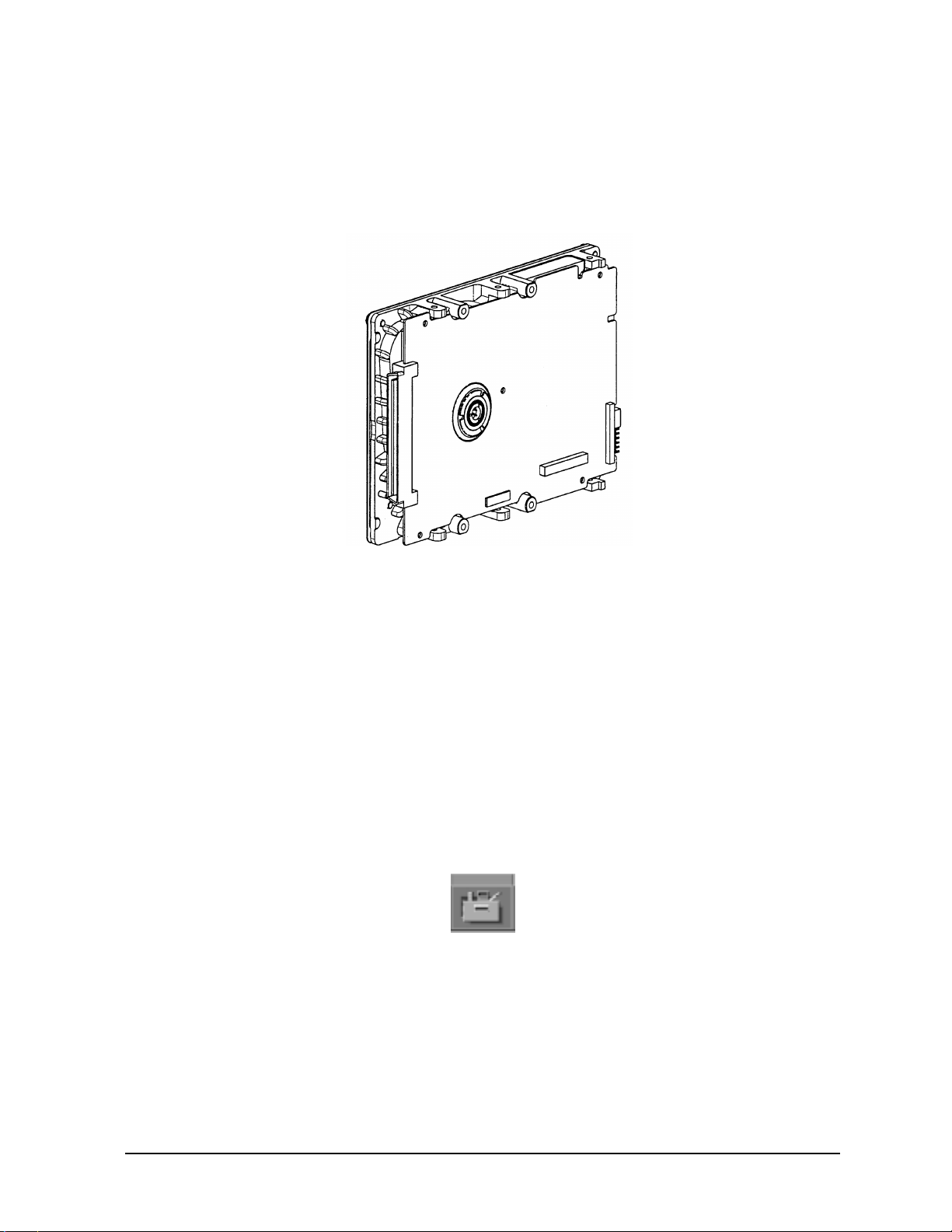
Figures 2-1 shows the type of hard disk drive supported for the HP workstation c-class.
Figure 2-1. Hard Drive, 9Gbyte/18Gbyte Ultra2 Low Voltage Differential
configuring a hard disk drive
This section describes how to add a hard drive to your system as a file system using SAM.
For more information about configuring a hard disk drive, refer to the manual Managing
Systems and Workgroups.
The procedures in this section require you to log in as root. If you cannot log in as root,
contact your system administrator.
1. Log in as root and create a mount directory (for example, /disk1).
2. Move the mouse pointer to the Application Manager control for tools and click the left
mouse button.
Chapter 2 39
Page 40

configuration
FRU configurations
3. Click twice on the System_Admin icon in the Application Manager window.
4. Click twice on the Sam icon in the Application Manager -- System_Admin window. If you are root, the System Application Manager (SAM) will appear on your screen; otherwise you will be asked to enter the root password and press Enter. The SAM window will appear. You will then need to re-execute steps 1 through 4.
5. Double click on the Disk and File System icon.
6. Double click on the Disk Devices icon.
The following screen message is displayed:
Scanning the system’s hardware...
The Disk and File Systems window opens containing a list of drives currently
configured on this system. You need to select one of the appropriate drives that is not in
use.
7. Click on Add in the Actions menu and select the item Not Using the Logical Volume Manager.
8. Enter the mount directory name in the Mount Directory field of the Add Disk window
and click on OK. The following message appears:
40 Chapter2
Page 41

FRU configurations
Task started.
Creating the device file...
Modifying “/etc/checklist”...
Task completed.
Click OK. You have successfully added a hard disk drive to your system unit.
configuration
Chapter 2 41
Page 42

configuration
FRU configurations
CD drive (optional) configuration
The optional CD drive connects to the ATAPI (IDE) interface in the CD drive bay
backplane within the HP workstation c-class via a 40-pin ribbon cable, a 4-pin audio cable,
and a 4-pin power cable. No interfacing addressing is required for the CD drive.
However, as shown in Figure 2-2. the CD drive should have a jumper set on the C SEL
(Cable Select) selection pins. (The CD drive should ship from the factory already jumpered
for C SEL.)
CAUTION
Figure 2-2. CD Drive Jumper Setting (Rear View)
CD-ROM drives are susceptible to mechanical and electrostatic shock. When
handling the drive, always wear the static-grounding wrist strap that came in
the CD-ROM drive kit. Always handle the drive carefully.
Jumpered for C SEL
See the section titled “installing a CD drive” on page 117 for installation details.
floppy disk drive (optional) configuration
The optional 3.5-inch floppy disk drive requires no ID, switch, or jumper settings. See the
section titled “installing a floppy disk drive” on page 125 for installation details.
CAUTION
42 Chapter2
Floppy disk drives are susceptible to mechanical and electrostatic shock.
When handling the drive, always wear the static-grounding wrist strap that
came in the floppy disk drive kit. Always handle the drive carefully.
Page 43

configuration
FRU configurations
memory
This workstation has 8 memory slots, labeled 0 through 7. Memory can be configured from
128MB to 1.4GB for the B1000 and 256 MB to 2 GB for the C3000. Memory does not have
to be configured in pairs for the HP workstation c-class, but must be loaded in the order
described in Figure 2-3.. Notice the alternating load pattern by location on the system
board.
Figure 2-3. Memory Connectors
Hard Disk
Drive Fan
CAUTION
The memory cards must be installed in the correct order, else the system will
not boot properly.
Chapter 2 43
Page 44

configuration
FRU configurations
The HP workstation c-class supports the 128 MByte DIMMs or the 256 MByte DIMMs. If
users install different size memory boards in a single unit, the largest size must be loaded
first then the smaller capacity memory boards for maximum performance. For example,
load a 256 MByte DIMM in slot 0 and a 128 MByte DIMM in slot 1.
NOTE
Users who wish to achieve both maximum performance and maximum future
capacity are advised to use 256 MB boards exclusively.
See the section titled “DIMM cards” on page 141 for details on installing memory. Also,
note that there is a label on the floor of the workstation’s interior showing the HP
workstation c-class memory loading order.
Use the Boot Console Handler to verify that the workstation recognizes the installed
memory. See “displaying the current memory configuration” on page 175 of this manual.
44 Chapter2
Page 45

configuration
FRU configurations
i/o cards
There are six I/O slots located on the rear panel of the HP workstation c-class. Slots 1
through 4 are full-size PCI slots. Slots 5 and 6 are half-size Peripheral Connect Interface
(PCI) slots. See Figure 2-4. for a brief description of slot capabilities.
Figure 2-4. PCI Card Slot Numbering and Capabilities
To maintain good graphics performance, you should always use slot 2 (SL2) as your
primary graphics card slot and slot 4 (SL4) as your secondary graphics card slot.
NOTE
If you connect your monitor to a different graphics card slot, you will need to
change the graphics path for that monitor. To do this see the section,
“Displaying and Setting the Monitor Type” in Chapter 6, Boot Console
Handler in this document.
See the section titled “i/o cards” on page 106 for details on installing I/O cards.
Chapter 2 45
Page 46

configuration
FRU configurations
monitor-type selection
The HP workstation c-class supports the following monitors:
• 19-inch, 1280×1024 color monitor, 75 Hz (A4575A)
• 19-inch, 1600×1200 color monitor, 75 Hz (A4575A)
• 21-inch, 1280×1024 color monitor (stereo capability), 75 Hz (A4576A)
• 21-inch, 1600×1200 color monitor, 75 Hz (A4576A)
The monitor type does not have to change since the workstation is set up to support the
above mentioned monitors. However, if for some reason the monitor type needs to
change, refer to Chapter 6, boot console handler, of this manual.
Note that connection to earlier HP monitors with 15-pin mini-DSub cables can be made
using the A4168A adapter cable shipped with your system miscellaneous kit.
NOTE
NOTE
Unsupported monitors may “lock up” if unable to sync to a scan rate provided
by the workstation.
The HP workstation c-class supports a maximum of four VISUALIZE-EG
graphics cards with four monitors. One, two, three, or four V
ISUALIZE-EG
graphics cards may be installed per workstation.
46 Chapter2
Page 47

3 troubleshooting
This chapter provides information about isolating a failing component, known as a Field
Replaceable Unit (FRU), in the HP workstation c-class.
47
Page 48

troubleshooting
To troubleshoot a HP workstation c-class, you must be familiar with the HP-UX operating
system and be able to start and stop processes. You should also be familiar with the boot
ROM diagnostics, and the Mesa (Support Tools Manager) on-line tests, which we describe
in this chapter.
As a super-user who is troubleshooting a HP-UX system, you should be able to shutdown
and reboot a system, start and stop processes, and examine error logs. You should also be
able to use systems utilities such as ioscan to check device files and configurations,
swlist to show loaded patches and software bundles, and SAM to configure and show
enabled services and configurations. You should also be familiar with STM, the on-line
diagnostics tool. You can view a man page on any of these on-line utilities or commands.
Note any error or status messages, then run the power-up boot ROM diagnostics, known as
Self Test. If the Self Test diagnostics fail, replace the FRU that is indicated. If the tests
pass, but you still suspect a problem, run the ISL diagnostics and Mesa (Support Tools
Manager) on-line tests.
For a complete description of using ISL diagnostics and using Mesa (Support Tools
Manager), refer to the website URL:
http://wojo.rose.hp.com/
48 Chapter3
Page 49

troubleshooting
flow diagrams for troubleshooting
flow diagrams for troubleshooting
The following four figures contain troubleshooting flowcharts you can follow to isolate a
failing Field Replaceable Unit (FRU). Figure 3-1., “Power On LCD, Troubleshooting Flow,”
contains the main troubleshooting flowchart. Figures 3-2 through 3-4 then contain
flowcharts for console, bootable device, and HP-UX troubleshooting, respectively.
NOTE
For the system to power up, the left side panel must be properly seated in the
mainframe chassis to engage the safety interlock switch.
Chapter 3 49
Page 50

troubleshooting
flow diagrams for troubleshooting
Figure 3-1. Power On LCD, Troubleshooting Flow
50 Chapter3
Page 51

Figure 3-2. Console Troubleshooting Messages
troubleshooting
flow diagrams for troubleshooting
Chapter 3 51
Page 52

troubleshooting
flow diagrams for troubleshooting
Figure 3-3. Bootable Device Troubleshooting
52 Chapter3
Page 53

Figure 3-4. Troubleshooting HP-UX Boot
troubleshooting
flow diagrams for troubleshooting
Chapter 3 53
Page 54

troubleshooting
identifying LCD-indicated conditions
identifying LCD-indicated conditions
This workstation uses an LCD panel to display firmware/OS progress codes. the codes,
referred to as chassis codes, consist of one of the mnemonics listed below, followed by a
4-digit hexadecimal number identifying the code module being executed. The mnemonics
and their meanings are:
FLT A hardware error has been detected
TST Hardware being tested
SHU System being shutdown
INI Hardware being initialized
WRN A non-optimal operating condition exists
RUN Computer is running operating system
In general, the LCD display has the following format:
ZZZ YYYY: FFFFFF
WWWWWWWWWWWWWWWW
ZZZ Three character chassis code mnemonic
YYYY Four digit hexadecimal code
FFFFFF Six character field replaceable unit description
WWWWWWWWWWWWWWWW Description of the chassis code
If the system encounters an FLT code while the system is booting, the FLT code is
interpreted and a message is displayed. For example, you may have information similar to
the following in the LCD:
FLT Three character chassis code mnemonic 30FC Four digit hexadecimal code SYS BD Six character field replaceable unit description
Line 1
Line 2
bad sys bd id Description of the chassis code
54 Chapter3
Page 55

troubleshooting
LCD fan failures and warnings
LCD fan failures and warnings
This section provides the failure and warning messages you will see in the LCD if there is
a problem with a fan in the HP workstation c-class.
A chassis code which indicates that a fan has failed (FLT D01n) or is running too slowly
(WRN D02n) within an HP workstation c-class specifies the fan number, n. Table 3-1., “Fan
Numbers and Corresponding Name,” lists the fan numbers and their names.
Table 3-1. Fan Numbers and Corresponding Name
Fan Number Name of the Fan
1 (not used) 2 Lower System Fan 3 Upper System Fan 4 PCI Card Fan 5 Turbo Cooler Fan, CPU 6 Disk/Memory Fan
Here is an example of a failure message for the I/O (PCI card) fan:
WRN D014 SYS BD
fan 4: failure!
Here is an example of a warning message for the Turbo Cooler Fan, CPU:
WRN D025 SYS BD
fan 5: too slow!
To locate the correct fan, see Figure 3-5.
Chapter 3 55
Page 56

troubleshooting
LCD fan failures and warnings
Figure 3-5. Fan Locations
Turbo Cooler
Fan (5)
Upper System
Fan (2)
Lower System
Fan (3)
PCI Card Fan (4)
Memory Fan
(6)
In the case of a fan problem, you will need to replace:
• The fan itself, if it is either a system board cooling fan, PCI (I/O) fan, or a memory fan.
• The entire system board tray assembly, if it is a turbo cooler fan (that is, a fan mounted
on a PA-8500 microprocessor on the system board)
See Chapter 4 , “field replaceable units,” for the procedures you should follow to remove
and replace these components.
56 Chapter3
Page 57

troubleshooting
dealing with a boot failure
dealing with a boot failure
To start this workstation from an operating system stored on a device different from the
usual boot device, to boot from a different disk, or to boot from another type of device (such
as DDS tape drive, an alternate hard disk or CD), see the following situations and
examples that use the Boot Console Handler. To access the Boot Console Handler, see
Chapter 6 of this manual.
• To boot from a known device containing a bootable operating system, type the following
at the prompt and press
Main Menu: Enter a command or a menu > boot device
where device is the hardware path to the device, specified in Mnemonic Style Notation
For example, to boot an operating system stored on a DDS-format tape in a drive
located at “scsi.1.0,” go to the Main Menu of the Boot Console Interface and then type
the following command at the prompt and press
Main Menu: Enter a command > boot scsi.1.0
Enter:
Enter:
The operating system on the specified device is used to start the workstation.
• To interact with the Initial System Loader (ISL) before booting the workstation, type
the following at the prompt and press
Enter:
Main Menu: Enter a command or a menu > boot <device>
You are prompted: Interact with ISL (Y or N) > y
Answering yes (y) causes the ISL to be loaded from the specified device. After a short
time, the following prompt appears on the screen:
ISL>
ISL is the program that actually controls the loading of the operating system. By
interacting with ISL, you can choose to load an alternate version of the HP-UX
operating system.
For example, if the usual kernel (/stand/vmunix for HP-UX 10.20) on the root disk
(fwscsi.6.0) has become corrupted, boot the workstation from the backup kernel
(/stand/vmunix.prev for HP-UX 10.20) by typing the following at the ISL> prompt
and press
Enter:
ISL> hpux /stand/vmunix.prev
• To find the location of the bootable operating systems on the various media in the file
system, use the search ipl command.
Chapter 3 57
Page 58

troubleshooting
dealing with a boot failure
searching for bootable media
To list all devices that may contain bootable media, go to the Main Menu of the Boot
Console Interface and then type the following at the prompt:
Main Menu: Enter a command or a menu > search ipl
The search may turn up more devices than there are lines on the display. If using a text
terminal, you can control the progress of the search from the terminal’s keyboard by
performing the following steps:
• To hold the display temporarily, press
• To continue the display, press
• To halt the search, press
Ctrl Q
Esc
Ctrl S
These flow-control commands do not work with a bitmapped display, but such a display can
show more than forty lines of text, so they are unnecessary.
To search for devices of just one type that actually contain bootable media, go to the Main
Menu of the Boot Console Interface and then type the following at the prompt:
Main Menu: Enter a command > search ipl device_type
where device_type is one of the following:
• fwscsi is the built-in fast, Ultra2 Wide LVD (Low Voltage Differential) SCSI bus.
• scsi is the built-in single-ended SCSI bus.
• lan is all connections to the built-in LAN.
• ide is the built-in CD-ROM drive.
n
• pci
is an optional SCSI interface in slot numbern.
stable storage
Stable Storage is non-volatile memory associated with each PA-RISC processor module.
Stable storage is used by the processor (CPU) to store device path information, the state of
the boot flags, HPMC error information, and operating system initialization data.
58 Chapter3
Page 59

troubleshooting
dealing with a boot failure
boot command notations
The boot command supports the following two notations:
• Mnemonic
• Path number
Type help scsi or help lan for more information on the boot path parameters.
Here are examples of mnemonic notation:
• boot with “no parameters” selects the primary boot path in stable storage.
• boot with the alternate or alt parameters selects the alternate boot path in stable
storage.
Here is an example of path number notation:
• boot p1 [Enter] attempts to boot from the second path in a list generated by a previous
search command.
supported boot paths
SCSI devices are bootable when connected to the SCSI port on the system. Diskless
workstations can only boot from the LAN port on the system board. The workstation can
be booted from the CD-ROM for software installation.
ISL environment
The ISL environment provides the means to load the operating system (HP-UX)
environment. The ISL environment also provides an off-line platform to execute diagnostic
and utility programs from a boot device when HP-UX does not load.
The ISL program is the first program loaded into main memory from an external media
(LAN, disk, or tape) and launched by the initial program loader (IPL) routine during the
Boot Administration environment.
The ISL environment provides the following capabilities:
• Execute user-entered commands to modify boot device paths and boot options in stable storage.
• Run off-line diagnostic programs and utilities.
• Provide automatic booting of the HP-UX operating system after power-on or reset.
The ISL program provides a stand-alone environment for loading off-line diagnostic and
utility programs from the LIF directory. The ISL program also provides user commands to
configure the boot parameters into Stable Storage.
Chapter 3 59
Page 60

troubleshooting
selftest failures
selftest failures
Chassis codes are the key to debugging selftest errors. If a failure is found during selftest,
chassis codes are displayed in the LCD. The procedure for using these codes to debug a
failure is as follows:
1. Using Table 3-2., “Chassis Codes for th HP Workstation C-Class,” find the chassis code
listed on the LCD.
2. To get additional information about failures from the Boot Console Handler, use the
Service Menu’s pim, pdt, and ChassisCodes commands.
In the following table, the FRU column shows messages printed on the LCD that refer to
system FRUs. Only FLT codes have FRUs associated with them. Some WRN codes are also
device specific, especially to IODC calls; for example, 8xxx codes. TST and INI codes do not
necessarily correspond to any FRU. All codes are listed in numeric order.
60 Chapter3
Page 61

troubleshooting
selftest failures
chassis codes
Table 3-2. lists all of the chassis codes for the HP workstation c-class.
Table 3-2. Chassis Codes for th HP Workstation C-Class
Ostat Code FRU Message Description
FLT 1n01 SYS BD HPMC occurred CPU n detected an unexpected HPMC. FLT 1n02 SYS BD powerfail intrpt CPU n detected an unexpected power fail
interrupt.
FLT 1n03 SYS BD recvry cntr trap CPU n detected an unexpected recovery
counter trap.
FLT 1n04 SYS BD external intrrpt CPU n detected an unexpected external
interrupt.
FLT 1n05 SYS BD LPMC occurred CPU n detected an unexpected LPMC. FLT 1n06 SYS BD ITLB mis/Ipg flt CPU n detected an unexpected ITLB miss
or instruction page fault.
FLT 1n07 SYS BD I mem prot trap CPU n detected anunexpected instruction
memory protection trap.
FLT 1n08 SYS BD illegal inst trp CPU n detected an unexpected illegal
instruction trap.
FLT 1n09 SYS BD break instr trap CPU n detected an unexpected break
instruction trap.
FLT 1n0A SYS BD privilgd op trap CPU n detected an unexpected privileged
operation trap.
FLT 1n0B SYS BD privlgd reg trap CPU n detected an unexpected privileged
register trap.
FLT 1n0C SYS BD overflow trap CPU n detected an unexpected overflow
trap.
FLT 1n0D SYS BD conditional trap CPU n detectedan unexpectedconditional
trap.
FLT 1n0E SYS BD assist exep trap CPU n detected an unexpected assist
exception trap.
FLT 1n0F SYS BD DTLB mis/Dpg flt CPU n detected an unexpected DTLB
miss or data page fault.
FLT 1n10 SYS BD non-acc ITLB mis CPU n detected an unexpected non-access
ITLB miss fault.
FLT 1n11 SYS BD non-acc DTLB mis CPU n detected an unexpected non-access
DTLB miss or data page fault.
FLT 1n12 SYS BD data mem prot tr CPU n detected an unexpected data
memory protection trap.
Chapter 3 61
Page 62

troubleshooting
selftest failures
Table 3-2. Chassis Codes for th HP Workstation C-Class
Ostat Code FRU Message Description
FLT 1n13 SYS BD data mem brk trp CPU n detected an unexpected data
memory break trap.
FLT 1n14 SYS BD TLB dirty bit tr CPU n detected an unexpected TLB dirty
bit trap.
FLT 1n15 SYS BD page refrnce trp CPU n detected an unexpected page
reference trap.
FLT 1n16 SYS BD assist emul trap CPU n detected an unexpected assist
emulation trap.
FLT 1n17 SYS BD hi-priv xfer trp CPU n detected an unexpected
higher-privilege transfer trap.
FLT 1n18 SYS BD lo-priv xfer trp CPU n detected an unexpected
lower-privilege transfer trap.
FLT 1n19 SYS BD taken branch trp CPU n detected an unexpected
taken-branch trap.
FLT 1n1A SYS BD data mem acc rts CPU n detected an unexpected data
memory access rights trap.
FLT 1n1B SYS BD data mem prot ID CPU n detected an unexpected data
memory protection ID trap.
FLT 1n1C SYS BD unalign data ref CPU n detected an unexpected unaligned
data reference trap.
FLT 1n1D SYS BD perf mon intrrpt CPU n detected an unexpected
performance monitor interrupt.
TST 1n20 SYS BD CPUn basic test CPU n is starting its basic operations
self-test.
TST 1n21 SYS BD CPUn alu test CPU n is starting its arithmetic and
logical unit self-test.
TST 1n22 SYS BD CPUn branch test CPU n is starting its branch instruction
self-test.
TST 1n23 SYS BD CPUn arith cond CPU n is starting its arthimetic condition
self-test.
TST 1n24 SYS BD CPUn bit opers CPU n is starting its bit operation
instruction self-test.
TST 1n25 SYS BD CPUn cntrl regs CPU n is starting its control register
self-test.
TST 1n26 SYS BD CPUn ext intrpt CPU n is starting its external interrupt
self-test.
62 Chapter3
Page 63

troubleshooting
selftest failures
Table 3-2. Chassis Codes for th HP Workstation C-Class
Ostat Code FRU Message Description
TST 1n27 SYS BD CPUn itimer test CPU n is starting its interval timer
self-test.
TST 1n28 SYS BD CPUn multi-media CPU n is starting its multi-media
instructions self-test.
TST 1n29 SYS BD CPUn shadow reg CPU n is starting its shadow register
self-test.
TST 1n2A SYS BD CPUn diagnse reg CPU n is starting its diagnose register
self-test.
TST 1n2B SYS BD CPUn rdr test CPU n is starting its remote diagnose
register self-test.
TST 1n2C SYS BD CPUn bypass test CPU n is starting its integer bypass
operation self-test.
TST 1n30 SYS BD CPUn start est CPU n is starting its early (pre-memory)
self-tests.
WRN 1n31 SYS BD CPUn skip est CPU n is bypassing its early self-tests to
save time.
FLT 1n32 SYS BD CPUn bad tst mod CPU n detected an unsupported system
mode.
INI 1n3C SYS BD CPUn initialize CPU n is initializing after self-tests. TST 1n3E SYS BD CPUn exit est CPU n finished its early self-tests. TST 1nA0 SYS BD CPUn fpu tests CPU n is starting its floating-point unit
self-tests.
TST 1nA1 SYS BD CPUn fpu reg tst CPU n is starting its floating-point
register self-test.
TST 1nA2 SYS BD CPUn fpu inst CPU n is starting its floating-point
instruction self-test.
TST 1nA3 SYS BD CPUn fpu traps CPU n is starting its floating-point trap
self-test.
TST 1nA4 SYS BD CPUn fpu misc CPU n is starting its floating-point
miscellaneous operations self-test.
TST 1nA5 SYS BD CPUn fpu bypass CPU n is starting its floating-point
bypassing self-test.
TST 1nB1 SYS BD CPUn TLB RAM tst CPU n is starting its TLB register
self-test.
TST 1nB2 SYS BD CPUn TLB trans CPU n is starting its TLB translation
self-test.
Chapter 3 63
Page 64

troubleshooting
selftest failures
Table 3-2. Chassis Codes for th HP Workstation C-Class
Ostat Code FRU Message Description
FLT 1nBA SYS BD monarch CPU FLT 1nBB SYS BD bad CPUn number The CPU identifier was out of range. FLT 1nBF SYS BD CPUn halt boot Bootstrap failure--machine halted. INI 1nCA SYS BD CPUn sys bus arb Monarch CPU is initializing the system
WRN 1nCD SYS BD CPUn deconfig CPU n deconfigured itself. WRN 1nCE SYS BD CPUn extinguish PDC_PROC halted CPU n. FLT 1nCF SYS BD slaven failed Slave CPU n failed self-test. WRN 1mDs SYS BD slaves deconfig Monarch CPU m deconfigured slave CPU
WRN 1nEF SYS BD CPUn slftst warn CPU n detected a non-fatal error during
WRN 1mFs SYS BD monm stop slave INI 1nFC SYS BD CPUn sync’ing CPU n is synchronizing with the rest of
INI 1nFD SYS BD CPUn stat wd tst CPU n is testing the system status word. FLT 1nFF SYS BD monarchn selftst Monarch CPU n failed self-test.
fail
The monarch CPU failed.
bus arbitration.
s.
its self-tests.
s
Monarch CPU m halted slave CPU s.
the system.
TST 2n20 SYS BD CPUn icache RAM CPU n is starting its instruction cache
RAM self-test.
FLT 2n25 SYS BD CPUn ic ld d err CPU n detected a data error during data
cache load.
FLT 2n26 SYS BD CPUn ic ld t err CPU n detected a tag error during data
cache load.
TST 2n30 SYS BD CPUn icache tag CPU n is starting its instruction cache tag
self-test.
TST 2n40 SYS BD CPUn icache par CPU n is starting its instruction cache
parity detection self-test.
TST 2n50 SYS BD CPUn dc stor que CPU n is starting its data cache store
queue self-test.
FLT 2n51 SYS BD CPUn dc st q err CPU n detected an error during its data
cache store queue self-test.
TST 2n70 SYS BD CPUn dcache RAM CPU n is starting its data cache RAM
self-test.
TST 2n80 SYS BD CPUn dcache tag CPU n is starting its data cache tag
self-test.
64 Chapter3
Page 65

troubleshooting
selftest failures
Table 3-2. Chassis Codes for th HP Workstation C-Class
Ostat Code FRU Message Description
TST 2n90 SYS BD CPUn dcache ECC CPU n is starting its data cache ECC
self-test.
FLT 2BAD SYS BD assertion fail A firmware assertion failed. TST 3n00 SYS BD ROM checksum tst Monarch CPU n is testing the boot ROM
integrity.
FLT 3n00 SYS BD ROM checksum BAD The boot ROM failed checksum. INI 3n00 SYS BD ROM checksum ok The boot ROM passed checksum. TST 3n01 SYS BD PDH control test Monarch CPU n is testing PDH control
register.
INI 3n01 SYS BD PDH control init Monarch CPU n is initializing the PDH
control register.
FLT 3n01 SYS BD PDH control err Monarch CPU n detected an error in the
PDH control register.
TST 3n02 SYS BD scratch RAM test Monarch CPU n is testing scratch RAM. INI 3n02 SYS BD scratch RAM ok The scratch RAM test failed. FLT 3n02 SYS BD scratch RAM bad The scratch RAM test passed. WRN 3n03 SYS BD stbl st read err CPU n detected a non-fatal error reading
the stable store.
FLT 3n03 SYS BD stbl st read err CPU n detected a non-fatal error reading
the stable store.
INI 3nC4 SYS BD clearing EEPROM Monarch CPU n is clearing the EEPROM. INI 3nD4 SYS BD deflting EEPROM2 Monarch CPU n is initializing the
EEPROM to system defaults.
WRN 3n04 SYS BD EEPROM write err CPU n detected a non-fatal error writing
the EEPROM.
FLT 3n04 SYS BD EEPROM write err CPU n detected a fatal error writing the
EEPROM.
FLT 3n05 SYS BD EEPROM wrt limit CPU n detected a fatal error writing the
EEPROM.
WRN 3n06 SYS BD EEPROM read err CPU n detected a non-fatal error reading
the EEPROM.
FLT 3n06 SYS BD EEPROM read err CPU n detected a fatal error reading the
EEPROM.
INI 3n07 SYS BD CPUn invoke LDB CPU n is starting the low-level debugger.
Chapter 3 65
Page 66

troubleshooting
selftest failures
Table 3-2. Chassis Codes for th HP Workstation C-Class
Ostat Code FRU Message Description
FLT 3n09 SYS BD bad sys mde byte CPU n detected an unsupported system
mode.
WRN 3n1A SYS BD hversion mismtch Stable store hardware version doesn’t
match system.
TST 3n1B SYS BD chck model strng Check model string with version in stable
store.
WRN 3n1B SYS BD model str msmtch Model string doesn’t match that in stable
store.
FLT 3n1B SYS BD fatal model str Error reading model string from stable
store.
TST 3n1C SYS BD test software ID Check LANIC address. WRN 3n1C SYS BD update sw ID Update LANIC address. FLT 3n1C SYS BD update sw ID err Error updating LANIC address. INI 3n2s SYS BD Invoke LDB: s CPU n is awaiting the low-level debugger
for s more seconds.
FLT 3nBC IO BD tick timeout The real-time clock is ticking too slowly or
not at all.
TST 3nBC IO BD test sys clocks CPU n is verifying processor clocks with
the real-time clock.
INI 3nBC SYS BD init sys clocks CPU n has initialized the processor clocks. FLT 3nCD IO BD RTC tick timeout The real time clock is ticking too slowly or
not at all.
TST 3nCD SYS BD check defaults CPUn is initializing stable store values to
system defaults.
INI 3nCD SYS BD init defaults CPU n finished initializing stable store
values.
FLT 3nCD SYS BD init EEPROM err CPU n detected an error writing to stable
store.
FLT 3nEC SYS BD bad sys config CPU n detected an illegal CPU board
configuration.
FLT 3nF4 SYS BD EEPROM boot limt CPU n detected a fatal error writing the
EEPROM.
FLT 3nFC SYS BD bad sys bd id CPU n cannot identify CPU board. TST 4n00 SYS BD CPUn start lst CPU n is starting its late (with memory)
self-tests.
66 Chapter3
Page 67

troubleshooting
selftest failures
Table 3-2. Chassis Codes for th HP Workstation C-Class
Ostat Code FRU Message Description
WRN 4n01 SYS BD CPUn skip lst CPU n is bypassing its late self-tests to
save time.
TST 4n0E SYS BD CPUn exit lst CPU n finished its late self-tests. TST 4n20 SYS BD CPUn lst erly st CPU n is re-executing some of its early
self-tests from system memory.
TST 4n21 SYS BD CPUn lst basic CPU n is re-executing its basic operations
self-test.
TST 4n22 SYS BD CPUn lst alu CPU n is re-executing its arithmetic and
logic unit self-test.
TST 4n23 SYS BD CPUn lst branch CPU n is re-executing its branch
instruction self-test.
TST 4n24 SYS BD CPUn lst arth cd CPU n is re-executing its arithmetic
conditions self-test.
TST 4n25 SYS BD CPUn lst bit ops CPU n is re-executing its bit operations
self-test.
TST 4n26 SYS BD CPUn lst ctl reg CPU n is re-executing its control register
self-test.
TST 4n27 SYS BD CPUn lst ext int CPU n is re-executing its external
interrupt self-test.
TST 4n28 SYS BD CPUn lst itimer CPU n is re-executing its interval timer
self-test.
TST 4n29 SYS BD CPUn lst mltimed CPU n is re-executing its multi-media
instructions self-test.
TST 4n2A SYS BD CPUn lst shadow CPU n is re-executing its shadow register
self-test.
TST 4n2B SYS BD CPUn lst dg regs CPU n is re-executing its diagnose
register self-test.
TST 4n2C SYS BD CPUn lst rdrs CPU n is re-executing its remote diagnose
register self-test.
TST 4n2D SYS BD CPUn lst bypass CPU n is re-executing its integer bypass
operation self-test.
TST 4n30 SYS BD CPUn cache byte CPU n is starting its data cache sub-word
operations self-test.
TST 4n40 SYS BD CPUn cache flush CPU n is starting its cache flush self-test. TST 4n50 SYS BD CPUn icache miss CPU n is starting its instruction cache
miss self-test.
Chapter 3 67
Page 68

troubleshooting
selftest failures
Table 3-2. Chassis Codes for th HP Workstation C-Class
Ostat Code FRU Message Description
TST 4n60 SYS BD CPUn dcache miss CPU n is starting its data cache miss
self-test.
FLT 5n00 SYS BD unknown bus err CPU n detected an unknown error on the
system bus (Runway).
FLT 5n02 SYS BD path err assertd CPU n detected a path error on the
system bus (Runway).
FLT 5n04 SYS BD data parity err CPU n detected a data, address, or control
parity error on the system bus (Runway).
FLT 5n07 SYS BD Runway dir error CPU n detected a directed error on the
system bus (Runway).
FLT 5n08 SYS BD Runway broad err CPU n detected a broadcast error on the
system bus (Runway).
FLT 5n0A SYS BD illegal response CPU n received data that did not match
any outstanding data request.
FLT 5n0B SYS BD bus timeout CPU n timed out before receiving
requested data. The responder is logged in
the system responder address.
FLT 5n0C SYS BD CPU sync failure CPU n’s synchronizer detected a rule
violation on the system bus (Runway).
INI 7000 DIMM start DIMM scan Start looking for installed DIMMs. INI 7002 SYS BD init mem tables Initialize memory data structures. FLT 7004 SYS BD mem plt upd fail Error updating memory platform data. FLT 7005 DIMM insufficient mem Insufficient memory detected to continue. TST 7010 DIMM check DIMM order Start memory DIMM order check. WRN 7011 DIMM skip DIMM ord ck Bypass memory DIMM order check. FLT 7012 DIMM DIMM order error Memory DIMMs are not in the proper
order.
FLT 7013 DIMM DIMM order error Memory DIMMs are not in the proper
order. As a result, the system cannot
access one or more DIMMs and has
deallocated all inaccessible DIMMs.
TST 7016 DIMM DIMM pair check Start memory DIMM pair check (DIMMs
in a pair (e.g. 0a/0b) must match in
J7000).
WRN 7017 DIMM skip mem pair ck Bypass memory DIMM set check. FLT 701F DIMM no memory found Memory scan couldn’t find any DIMMs.
68 Chapter3
Page 69

troubleshooting
selftest failures
Table 3-2. Chassis Codes for th HP Workstation C-Class
Ostat Code FRU Message Description
TST 7020 SYS BD search for IMM Try to find a single memory bank to use
for the initial memory module.
TST 703s DIMM DIMMs IMM vrfy DIMM s was the initial memory module
last boot. Verify it still works.
FLT 704s DIMM DIMM s IMM fail DIMM s failed the initial memory module
test.
TST 705s DIMM DIMM s IMM test Test DIMM in slot s as the initial memory
module.
INI 706s DIMM DIMM s is IMM DIMM s chosen as initial memory module. INI 70F0 DIMM DIMM scan done Memory DIMM scan complete. TST 7100 SYS BD mem register tst Start testing registers in memory
controller.
WRN 7101 SYS BD skip mem reg tst Bypass the memory controller register
test.
FLT 7102 SYS BD mem addr reg tst Firmware detected an error in the
memory controller address registers.
FLT 7103 SYS BD mem mbat reg tst Firmware detected an error in the
memory controller bank registers.
FLT 7104 SYS BD mem reg tst fail Firmware detected an error in the
memory controller memory registers.
FLT 7105 SYS BD mem err reg test Firmware detected an error in the
memory controller error registers.
FLT 7106 SYS BD mem err clr fail Firmware was unable to clear the error
registers after testing.
INI 7200 DIMM strt DIMM detect Start the Serial Presence Detection (SPD)
to search for memory DIMMs.
INI 7201 DIMM DIMM detectx% SPD is x% finished. WRN 7202 SYS BD skip DIMM detect Bypass Serial Presence Detection. FLT 7203 DIMM unsupp DIMM type SPD found an unsupported DIMM type. FLT 7204 DIMM SPD fatal error SPD detected an unexpected, fatal error. INI 7205 DIMM add HP DIMM type New HP manufactured DIMM type added
to tables.
INI 7206 DIMM non-HP DIMM type New non-HP DIMM type added to tables
(use at own risk).
Chapter 3 69
Page 70

troubleshooting
selftest failures
Table 3-2. Chassis Codes for th HP Workstation C-Class
Ostat Code FRU Message Description
FLT 7207 DIMM DIMM table full The DIMM table is full--cannot add new
type.
FLT 7208 DIMM no DIMMs found SPD didn’t find any memory DIMMs. INI 721s DIMM is DIMMs inst? SPD is checking memory slot s. INI 722s DIMM ???? DIMM in
INI 723s DIMM 128M DIMM in INI 724s DIMM 256M DIMM in INI 725s DIMM 512M DIMM in FLT 72As DIMM DIMMs checksum DIMM in slot s failed SPD checksum and
FLT 72Cs DIMM DIMMs mismatch DIMM in slot s didn’t match the other in
FLT 72D
INI 7300 SYS BD mem config start Starting main memory configuration. TST 7301 SYS BD check mem config Checking for memory configuration
WRN 7302 SYS BD mem confg changd Memory physical configuration changed
s
DIMM DIMMs load err Memory DIMMs are not in the proper
s
s
s
s
SPD found a DIMM in slot s, but can’t determine its size. DIMM will not be used.
SPD found a 128MB DIMM in slot s.
SPD found a 256MB DIMM in slot s.
SPD found a 512MB DIMM in slot s.
will not be used.
pair. (J7000 only--DIMMs must be in
matched pairs.)
order. As a result, the system cannot
access DIMM s and has deallocated it.
change since last boot.
since last boot.
INI 7303 SYS BD use saved config Memory physical configuration didn’t
change. Use stored configuration data.
INI 7304 SYS BD build mem intrlv Building memory configuration with all
DIMMs interleaved.
INI 7305 SYS BD save mem config Savingmemory configuration information
in non-volatile memory.
WRN 7306 SYS BD use alt mem conf Memory will be configured from fixed
values, instead of detected DIMMs.
INI 7307 SYS BD interleve memory Generating the memory interleave. FLT 7308 SYS BD PDT is disabled Firmware detected bad memory pages,
but the Page Deallocation Table is
disabled.
FLT 7309 DIMM insufficient mem Insufficient error-free memory to
continue.
70 Chapter3
Page 71

troubleshooting
selftest failures
Table 3-2. Chassis Codes for th HP Workstation C-Class
Ostat Code FRU Message Description
FLT 730C SYS BD mem intrlv fail Memory interleave generation failed. INI 730F SYS BD mem config done Main memory configuration complete. TST 7400 DIMM non-dest mem tst Starting non-destructive memory test. TST 740F DIMM non-dst tst done Non-destructive memory test complete. INI 7500 SYS BD memory reset Resetting memory system. WRN 7501 SYS BD mem log clr warn Memory error logs didn’t clear on first try. FLT 7502 SYS BD mem err log fail Firmware could not clear memory error
logs.
TST 7600 DIMM dest mem test Starting the destructive memory test. WRN 7601 DIMM mem init only Skip the test, just initialize memory to
save time.
TST 7602 DIMM tst 1st mem page Starting 3-pass test of first memory page. TST 7603 DIMM tst rest of mem Starting 3-pass test of the rest of memory. TST 7604 DIMM start 1st pass Starting 1st pass of memory test (write
pseudorandom sequence).
TST 7605 DIMM 1st pass TST 7606 DIMM start 2nd pass Starting 2nd pass of memory test (verify
TST 7607 DIMM 2nd pass TST 7608 DIMM start 3rd pass Starting 3rd pass of memory test (verify
TST 7609 DIMM 3rd pass x% Third pass is x% complete. TST 760A DIMM start mem init Starting memory initialization. (Initialize
TST 760B DIMM mem init WRN 760C DIMM repeat dest test Re-execute destructive test for hardware
FLT 760D DIMM mem code cpy err Firmware tried to copy code from ROM to
x%
x%
x%
First pass is x% complete.
pseudorandom sequence, write inverse).
Second pass is x% complete.
inverse sequence).
to zero to set ECC.)
Memory initialization is x% complete.
troubleshooting.
memory, but the copy didn’t match the
original.
FLT 7610 DIMM ECC wrt/read err Writing and reading back good data
caused memory ECC error.
FLT 7611 DIMM ECC single data Memory ECC test failed to detect
single-bit data error.
Chapter 3 71
Page 72

troubleshooting
selftest failures
Table 3-2. Chassis Codes for th HP Workstation C-Class
Ostat Code FRU Message Description
FLT 7612 DIMM ECC single ECC Memory ECC test failed to detect
single-bit ECC error.
FLT 7613 DIMM ECC multipl data Memory ECC test failed to detect
multiple-bit data error.
FLT 7614 DIMM ECC multpl signl Memory ECC test failed to signal
multiple-bit error.
FLT 7800 SYS BD mem err summary Printing memory error summary word to
RS-232.
FLT 7801 SYS BD bus ctrl par err System bus (Runway) control parity error
detected.
FLT 7802 SYS BD bus addr par err System bus (Runway)address parity error
detected.
FLT 7803 SYS BD bus data par err System bus (Runway) data parity error
detected.
FLT 7804 SYS BD mem out of range Memory access outside configured
memory space.
FLT 7805 SYS BD bus broadcst err System bus (Runway) broadcast error
detected.
FLT 7806 SYS BD mem addr par err Memory bus address parity error
detected.
FLT 7807 SYS BD mem ctlr stat wd Printing memory controller status word to
RS-232.
FLT 781s SYS BD DIMM s uncor err Uncorrectable ECC error detected in
DIMM s.
FLT 782s SYS BD DIMM s corr err Correctable ECC error detected in DIMM
s.
FLT 7840 SYS BD unexpected HPMC Unexpected HPMC detected. FLT 7841 SYS BD mem status invld Memory error status word is invalid. FLT 7842 SYS BD mem summ invalid Memory summary word is invalid. FLT 7843 SYS BD fwd prog invalid Memory forward progress word is invalid. FLT 7844 SYS BD mem HPMC summ wd Printing memory error summary word to
RS-232.
FLT 7845 SYS BD mem ctlr stat wd Printing memory controller status word to
RS-232.
FLT 7846 SYS BD mem err overflow Multiple memory errors detected.
72 Chapter3
Page 73

selftest failures
Table 3-2. Chassis Codes for th HP Workstation C-Class
Ostat Code FRU Message Description
FLT 7848 SYS BD addr not mapped Memory address outside configured
memory space.
troubleshooting
FLT 785s DIMM MBE in DIMM
FLT 786s DIMM SBE&MBE DIMM
FLT 787s DIMM mem err DIMM
FLT 788s DIMM SBE in DIMM
FLT 7890 DIMM MBE overwrt SBE Firmware replaced a correctable memory
FLT 7891 DIMM dup entry in PDT The PDT already contains an entry at
FLT 7892 SYS BD PDT write error Error adding the entry to the PDT. FLT 7893 SYS BD PDT is full The PDT is full--cannot add new entry. FLT 7900 SYS BD no DMT entry Internal error--cannot find DIMM entry. FLT 7901 SYS BD no rank entry Internal error--cannot find rank entry.
s
s
s
s
Destructive memory test detected an uncorrectable memory error in DIMM s.
Destructive memory test detected both an uncorrectable and a correctable memory error in DIMM s.
Destructive memory test detected a pattern compare error in DIMM s.
Destructive memory test detected a correctable memory error in DIMM s.
error entry in the PDT with an
uncorrectable memory error entry at the
same address.
that address.
FLT 7902 SYS BD bad refrsh intvl Computed refresh interval is invalid. FLT 7903 SYS BD mem intrlv fail Cannot generate memory interleave. FLT 7904 SYS BD mem reloc failed Cannot interleave with relocated range
(3.75GB - 4.0GB).
FLT 7905 SYS BD mem intrlv error Undefined memory interleave failure. FLT 79FF SYS BD mem firmware err Internal error--never expected this to
happen.
WRN 80F3 SYS BD err rd IODC byte Cannot read IODC from ROM or card. WRN 80F4 EXT IO boot read error Cannot load IODC entry_init for boot
device.
WRN 80F5 EXT IO boot exec error Error initializing boot device. WRN 80F6 EXT IO boot read error Cannot load IODC entry_io for boot
device.
WRN 80F7 EXT IO boot IO error Error detected during boot device I/O.
Chapter 3 73
Page 74

troubleshooting
selftest failures
Table 3-2. Chassis Codes for th HP Workstation C-Class
Ostat Code FRU Message Description
WRN 80F8 EXT IO invalid boot dev Invalid boot device class; bad IODC? WRN 80FC EXT IO invalid boot dev Unexpected error; bad IODC? INI 8800 IOCARD PCI BusWlk start Starting PCI bus and device discovery. INI 88r1 IOCARD PCI Rope r walk Starting PCI bus and device discovery on
Rope r. INI 8802 IOCARD PCI BusWalk done PCI bus and device discovery complete. INI 8803 SYS BD PCI alloc done Done allocating address space for PCI
devices.
INI 8804 SYS BD PCI config done Done configuring PCI devices. FLT 881r IO B D R2PCIr not found Rope-to-PCI bridge r not found. FLT 883
FLT 884r EXT IO Rope r tgl fail Rope r debug register toggle failed. INI 8850 SYS_BD early rope0 init Initializing rope 0 for early RS-232
FLT 8850 SYS_BD rope0 init fail Couldn’t initialize rope 0. INI 8860 SYS_BD rope0 init done Rope 0 initialization complete. INI 8870 IO_BD early R2PCI init Initializing rope-to-PCI bridge 0 for early
FLT 8870 IO_BD R2PCI init fail Couldn’t initialize rope-to-PCI bridge 0. INI 8880 IO_BD R2PCI init done Rope-to-PCI bridge 0 initialization. INI 8890 IO_BD early Super init Iniitalizing Super-I/O for early RS-232
FLT 8890 IO_BD Super init fail Couldn’t initialize Super-I/O. INI 88A0 IO_BD Super init done Super-I/O initialization complete. WRN 8A03 EXT IO No graph console Cannot re-establish communications with
r
IO B D Roper config
err
PCI configuration failed below
Rope-to-PCI bridge r.
output.
RS-232 output.
output.
the graphics console. WRN 8A04 EXT IO No USB keyboard Cannot re-establish communications with
the USB keyboard.
TST 8C06 EXT IO PCI BIST test Running PCI Built-In Self-Test WRN 8C07 EXT IO PCI BIST error PCI Built-In Self-Test failed. WRN 8C08 SYS BD PCI alloc error PCI address space allocation failed. WRN 8C09 IO BD PCI mem mngr err Memory allocation for PCI device failed.
74 Chapter3
Page 75

troubleshooting
selftest failures
Table 3-2. Chassis Codes for th HP Workstation C-Class
Ostat Code FRU Message Description
WRN 8C0A EXT IO PCI mem type err PCI device requested invalid memory
type.
WRN 8C0B IO BD PCI max bus dpth PCI bus depth exceeded maximum
supported depth.
WRN 8C0C EXT IO PCI dev not cnfg Unable to configure PCI device. WRN 8C0F IO BD dev tree ovrflow Data space for PCI devices is full. WRN 8DEC IO BD init LAN SROM Initializing the core LAN serial EPROM. SHU 8DEC IO BD resetting system Restarting system after core LAN
initialization.
FLT 8E10 IO BD PARALEL port cfg Parallel port configuration failed. FLT 8E11 IO BD SERIAL1 port cfg Serial 1 port configuration failed. FLT 8E12 IO BD SERIAL2 port cfg Serial 2 port configuration failed. FLT 8E13 IO BD FLOPPY drive cfg Floppy drive configuration failed. FLT 8E20 IO BD bad USB port cfg USB port configuration failed. WRN 9001 EXT IO no console found Search for console display device failed. INI 9151 IO BD init SERIAL_1 Initializing serial 1 port as console
display.
INI 9152 IO BD init SERIAL_2 Initializing serial 2 port as console
display.
INI 915F IO BD init unknown dev Initializing unknown device as console
display.
INI 916s EXT IO init PCI slot
INI 91DB IO BD init SERIAL_LDB Initializing serial LDB port as console
INI 9C51 IO BD consol is SER_1 Console display is on serial port 1. WRN 9C51 IO BD bad init SERIAL1 Serial port 1 failed to initialize as a
INI 9C52 IO BD consol is SER_2 Console display is on serial port 2.
s
Initializing PCI device in slot s as console display.
display.
console device.
WRN 9C52 IO BD bad init SERIAL2 Serial port 2 failed to initialize as a
console device.
INI 9C6s EXT IO consol is GRAPH
Chapter 3 75
s
Console display is on graphics card in PCI slot s.
Page 76

troubleshooting
selftest failures
Table 3-2. Chassis Codes for th HP Workstation C-Class
Ostat Code FRU Message Description
WRN 9C6s EXT IO bad PCI slot
INI 9C8t EXT IO cnfg mon type
WRN 9C8t EXT IO mon type t fail Failedto configure consoleto monitor type
INI 9CDB IO BD consl is SER_LDB Console display is on serial LDB port. WRN 9CDB IO BD bad init SER_LDB Serial LDB port failed to initialize as a
FLT A088 IO BD consl path fault Unable to boot--no console device found. WRN A008 EXT IO no boot device Unable to boot--no bootable device found. WRN A0BD EXT IO device not ready Boot device not ready--operation may be
FLT A0FF EXT IO unknown launch Unable to boot. Explanation may appear
WRN A50F EXT IO init pri pth err Unable to boot from primary boot device. WRN A70F EXT IO init otr pth err Unable to boot from non-primary boot
s
Graphics in PCI slot s failed to initialize
as a console device.
t
Set graphics console to monitor type t.
(Seen when cycling through types.)
t.
console device.
retried.
on console.
device. INI C10m SYS BD CPUm is monarch CPU m was chosen as the monarch
processor. (All other CPUs are slaves.) INI C30m SYS BD monarchm test CPU m finished the monarch-only tests
and system initialization. INI C30C SYS BD mnrch slv chck The monarch CPU is checking whether
the slaves are in the correct rendezvous. INI C3FF SYS/IO late monarch tst The monarch CPU is starting the late
(post-memory) monarch-only tests. FLT C3FF SYS/IO late monarch flt The late (post-memory) monarch-only
tests failed.
INI C4CC SYS BD initialize ccp Searching for (lab-only) debugger card. INI C4CD SYS BD no ccp found Debugger card not found. INI C4CE SYS BD ccp disabled Debugger card disabled. INI C4CF SYS BD ccp found Debugger card found. INI C500 SYS BD get primary path Autoboot is reading primary boot path
from stable store.
76 Chapter3
Page 77

troubleshooting
selftest failures
Table 3-2. Chassis Codes for th HP Workstation C-Class
Ostat Code FRU Message Description
INI C540 EXT IO init pri path Autoboot is trying to boot from primary
boot device.
INI C580 EXT IO load IPL pri pth Loading IPL from primary boot device. WRN C5F0 EXT IO err read pri IPL Error loading IPL from primary boot
device.
FLT C5F0 EXT IO pri IPL fault Error loading IPL from primary boot
device.
WRN C5F1 EXT IO err read pri IPL Cannot load IPL from primary boot
device--load address invalid.
WRN C5F2 EXT IO err read pri IPL Cannot load IPL from primary boot
device--file is not IPL image.
WRN C5F3 EXT IO err read pri IPL Cannot load IPL from primary boot
device--IPL image size invalid.
WRN C5F4 EXT IO err read pri IPL Cannot load IPL from primary boot
device--IPL entry point address invalid.
WRN C5F8 EXT IO err read pri IPL Cannot load IPL from primary boot
device--IPL image checksum failed.
INI C5FF <blank> launch pri IPL Booting from primary boot path. INI C642 EXT IO init kybrd consl Try to initialize USB keyboard. FLT C642 EXT IO kybd error Anerror was detected trying to access the
keyboard.
WRN C643 EXT IO keyboard reinit Keyboard was re-initialized. WRN C64F EXT IO reset montr type The console device failed to initialize with
the given monitor type. Try again with
type 1.
TST C68s SYS BD test graph in INI C68s SYS BD init graph in s Successfully initialized graphics card in
WRN C68s SYS BD fail graph in
INI C740 EXT IO init other path Autoboot is trying to boot from
s
Look for graphics card in PCI slot s.
PCI slot s.
s
Card in PCI slot s failed graphics initialization or is not a graphics card.
non-primary boot device.
INI C780 EXT IO ld IPL othr path Loading IPL from non-primary boot
device.
WRN C7F0 EXT IO other IPL fault Error loading IPL from non-primary boot
device.
Chapter 3 77
Page 78

troubleshooting
selftest failures
Table 3-2. Chassis Codes for th HP Workstation C-Class
Ostat Code FRU Message Description
WRN C7F1 EXT IO bad alt IPL read Cannot load IPL from non-primary boot
device--load address invalid. WRN C7F2 EXT IO bad alt IPL read Cannot load IPL from non-primary boot
device--file is not IPL image. WRN C7F3 EXT IO bad alt IPL read Cannot load IPL from non-primary boot
device--IPL image size invalid. WRN C7F4 EXT IO bad alt IPL read Cannot load IPL from non-primary boot
device--IPL entry point address invalid. WRN C7F8 EXT IO bad alt IPL read Cannot load IPL from non-primary boot
device--IPL image checksum failed. WRN C7FF <blank> launch IPL other Booting from a device other than the
primary boot path. INI CB00 SYS BD TOC initiated A Transfer of Control entered the
firmware TOC handler. WRN CB01 SYS BD no OS TOC vector There is no TOC vector for the operating
system. Firmware will soft boot the
system. WRN CB02 SYS BD bad OS TOC addr The operating system TOC handler vector
is invalid. Firmware will soft boot the
system. WRN CB03 SYS BD bad OS TOC code The operating system TOC handler is
invalid. Firmware will soft boot the
system. WRN CB04 SYS BD bad OS TOC len The size of the operating system TOC
handler is invalid. Firmware will soft boot
the system. WRN CB05 SYS BD bad OS TOC chksm The operating system TOC handler failed
the checksum test. Firmware will soft boot
the system. WRN CB0A SYS BD prev TOC logged Firmware detected unread PIM data from
a previous TOC and will not overwrite it.
(PIM for this TOC is lost.) INI CB0B SYS BD branch to OS TOC Branching to the operating system TOC
handler. WRN CB0C SYS BD br OS TOC failed Branch to the operating system TOC
handler failed.Firmware will soft boot the
system.
78 Chapter3
Page 79

troubleshooting
selftest failures
Table 3-2. Chassis Codes for th HP Workstation C-Class
Ostat Code FRU Message Description
WRN CB10 SYS BD LPMC initiated A Low-Priority Machine Check entered
the firmware LPMC handler. The handler
should log the error and return to normal
operation.
WRN CB11 SYS BD icache LPMC err An instruction cache parity error caused
the LPMC.
WRN CB12 SYS BD dcache LPMC err A data cache parity/ECC error caused the
LPMC.
WRN CB13 SYS BD dcache tag error The parity error is in the tag portion of
the data cache.
WRN CB14 SYS BD dcache data err The parity error is in the data portion of
the data cache.
FLT CB1F SYS BD OS LPMC failed Firmwarecouldn’tbranch tothe operating
system LPMC handler. It will halt the
CPU, requiring a power cycle to recover.
WRN CB71 SYS BD HPMC occurred A High-Priority Machine Check caused
entry to PDCE_CHECK (the firmware
trap handler).
WRN CB72 SYS BD LPMC occurred A Low-Priority Machine Check caused
entry to PDCE_CHECK (the firmware
trap handler).
WRN CB73 SYS BD TOC occurred A Transfer of Control caused entry to
PDCE_CHECK (the firmware trap
handler).
FLT CB9r IO BD Error on roper An error was detected on rope r. FLT CB99 SYS BD seed IVA handler PDC_SEED_ERROR triggered an HPMC. FLT CB9A SYS BD HPMC overwrite Firmware is overwriting PIM data from a
previous HPMC.
OFF CBA1 SYS BD AIOC int dat err I/O controller internal error. OFF CBA2 IO BD EtoA rope perr Parity error between I/O controller and
Rope-to-PCI bridge.
OFF CBA3 SYS BD access invld TLB An invalid I/O TLB entry was accessed. OFF CBA4 IO BD EtoA rp cmd perr Command parity error between I/O
controller and Rope-to-PCI bridge.
OFF CBA5 IO BD CDF timeout Rope Command/Data FIFO is backed up.
Chapter 3 79
Page 80

troubleshooting
selftest failures
Table 3-2. Chassis Codes for th HP Workstation C-Class
Ostat Code FRU Message Description
OFF CBA6 IO BD R2PCI resp tmout Rope-to-PCI bridge timed out. Could be a
failure of the PCI card, rope, or R2PCI
bridge.
OFF CBA7 IO BD Unknown AIOC err Unknown I/O controller error. OFF CBB1 IO BD PCI timeout A PCI card requested the bus but failed to
use it. OFF CBB2 IO BD PCI timeout; OV More than once aPCI card requested the
bus but failed to use it.
OFF CBB3 IO BD R2PCI intrnl err Rope-to-PCI bridge internal error. OFF CBB4 IO BD R2PCI int err;OV Multiple Rope-to-PCI bridge internal
errors. OFF CBB6 IO BD PCI data req err PCI bus data requestor error: R2PCI
detected PERR# assertion. OFF CBB8 IO BD PCI D req err;OV Rope-to-PCI bridge detected multiple
PERR# assertions.
OFF CBBA IO BD PCI data par err PCI bus data parity error. OFF CBBC IO BD PCI Dpar err;OV Multiple PCI bus data parity errors. OFF CBBE IO BD R2PCI intrnl err Error in R2PCI internal data to PCI bus. OFF CBC0 IO BD R2PCI int err;OV Multiple R2PCI internal data to PCI bus
errors. OFF CBC2 IO BD PCI data parity PCI data parity error. I/O error log word 3
contains the error address. OFF CBC4 IO BD PCI data par; OV Multiple PCI data parity errors. I/O error
log word 3 contains the error address. OFF CBC6 IO BD R2PCI intrnl err Rope-to-PCI bridge internal data error:
R2PCI detected PERR# assertion. OFF CBC8 IO BD R2PCI int err;OV Multiple R2PCI internal data errors:
R2PCI detected multiple PERR#
assertions. OFF CBCA IO BD PCI data rs err PCI bus data responder error: R2PCI
detected PERR# assertion. OFF CBCC IO BD PCI D rs err; OV Multiple PCI bus data responder errors:
R2PCI detected multiple PERR#
assertions. OFF CBCE IO BD R2PCI T-Abort Rope-to-PCI bridge signalled Target
Abort.
80 Chapter3
Page 81

troubleshooting
selftest failures
Table 3-2. Chassis Codes for th HP Workstation C-Class
Ostat Code FRU Message Description
OFF CBD0 IO BD R2PCI T-Abort;OV Rope-to-PCI bridge signalled multiple
Target Aborts.
OFF CBD2 IO BD PCI parity err PCI address/command parity error. OFF CBD4 IO BD PCI par err; OV Multiple PCI address/command parity
errors.
OFF CBD6 IO BD PCI no DEVSEL# No PCI device selected (DEVSEL#
assertion). I/O error log word 3 contains
the error address.
OFF CBD8 IO BD PCI no DEVSEL;OV Multiple DEVSEL# assertions. I/O error
log word 3 contains the error address.
OFF CBDA IO BD PCI target abort A PCI device signalled Target Abort. I/O
error log word 3 contains the error
address.
OFF CBDC IO BD PCI T-Abort; OV A PCI device signalled multiple Target
Aborts. I/O error log word 3 contains the
error address.
OFF CBDD IO BD PCI assrts LOCK# A PCI device asserted LOCK#. OFF CBDE IO BD PCI LOCK#; OV A PCI device asserted LOCK# multiple
times.
OFF CBE0 IO BD PCI assrts SERR# A PCI device asserted SERR#: address
parity error or other system error.
OFF CBE2 IO BD PCI SERR#; OV A PCI device asserted SERR# multiple
times.
OFF CBE3 IO BD Unknown PCI err Unknown PCI error detected. OFF CBE6 SYS BD AtoE rope perr Parityerror between systemI/O controller
and Rope-to-PCI bridge.
OFF CBE7 IO BD R2PCI intrnl err Rope-to-PCI bridge internal data error. OFF CBE8 SYS BD AtoE rope perr Command parity error between system
I/O controller and Rope-to-PCI bridge.
OFF CBE9 IO BD Unknown Rope err Unknown rope error occurred. FLT CBF0 SYS BD HPMC initiated A High-Priority Machine Check entered
the firmware HPMC handler.
FLT CBF1 SYS BD no OS HPMC IVA There is no HPMC vector for the
operating system. Firmware will halt the
CPU, requiring a power cycle to recover.
Chapter 3 81
Page 82

troubleshooting
selftest failures
Table 3-2. Chassis Codes for th HP Workstation C-Class
Ostat Code FRU Message Description
FLT CBF2 SYS BD bad OS HPMC len The size of the operating system HPMC
handler is invalid. Firmware will halt the
CPU, requiring a power cycle to recover. FLT CBF3 SYS BD bad OS HPMC addr The operating system HPMC handler
vector is invalid. Firmware will halt the
CPU, requiring a power cycle to recover. FLT CBF4 SYS BD bad OS HPMC cksm The operating system HPMC handler
failed the checksum test. Firmware will
halt the CPU, requiring a power cycle to
recover. FLT CBF5 SYS BD OS HPMC vector 0 The size of the operating system HPMC
handler is zero. Firmware will halt the
CPU, requiring a power cycle to recover. WRN CBFA SYS BD prev HPMC logged Firmware detected unread PIM data from
a previous HPMC and will overwrite it. FLT CBFB SYS BD brnch to OS HPMC Branching to the operating system HPMC
handler. FLT CBFC SYS BD OS HPMC br err Branch to the operating system HPMC
handler failed. Firmware will halt the
CPU, requiring a power cycle to recover. FLT CBFD SYS BD unknown check The firmware trap handler didn’t detect
an HPMC, LPMC, or TOC. FLT CBFE SYS BD HPMC during TOC A High-Priority Machine Check occurred
during Transfer of Control processing. FLT CBFF SYS BD multiple HPMCs A High-Priority Machine Check occurred
while processing another HPMC. INI CC0n SYS BD CPUn OS rendezvs Slave CPU n entering the final
rendezvous, waiting for the operating
system to awaken it. INI CC1n SYS BD CPUn early rend Slave CPU n entering the early
rendezvous, waitingfor the monarch CPU
to initialize scratch RAM and other
system state. INI CC2n SYS BD CPUn rendezvous Slave CPU n entering rendezvous. Slave
CPUs enter this rendezvous numerous
times during boot. INI CC3n SYS BD CPUn cache rend Slave CPU n entering cached rendezvous,
waiting for the monarch CPU to configure
the system bus.
82 Chapter3
Page 83

troubleshooting
selftest failures
Table 3-2. Chassis Codes for th HP Workstation C-Class
Ostat Code FRU Message Description
INI CC4n SYS BD CPUn mem rendez Slave CPU n entering memory
rendezvous, waitingfor the monarch CPU
to select a boot device.
TST D000 SYS BD micro controller Firmware is initializing communications
with the system controller.
WRN D004 SYS BD micro not resp Firmware detected a communications
error with the system controller.
INI D005 SYS BD set dom1 fan spd Firmware is initializing communications
with the system controller.
INI D006 SYS BD set dom2 fan spd Firmware is initializing communications
with the system controller.
WRN D007 SYS BD bad microctl cmd Firmware detected a communications
error with the system controller.
FLT D01n SYS/IO fan n: failure! Firmware detected system fan n stopped. WRN D02n SYS/IO fan n: too slow! Firmware detected system fan n is
running too slowly.
memory failures
The HP workstation c-class system requires Memory Page Deallocation to be
implemented. This feature allows the workstation to provide information to the operating
system about memory failures.
The HP-UX operating uses information to map out failing memory areas and continue
normal operation. You can use the command memrpt with the detail switch to obtain
information about the Memory Page Deallocation Table (PDT) as well as single-bit errors
logged by the system.
# /usr/sbin/sysdiag Enter DUI > logtool Enter LOGTOOL> memrpt detail Enter
The PDT can also be checked using the pdt command in the Service menu of the Boot
Console Handler (refer to “boot console menus” on page 159).
For allowable memory configurations see Chapter 2 of this manual.
Chapter 3 83
Page 84

troubleshooting
running system verification tests
running system verification tests
HP-UX uses an on-line diagnostics product named Mesa (Support Tools Manager) that
allows system operation verification.
Three interfaces are available with the Support Tools Manager:
• a command line interface (accessed through the cstm command)
• a menu-driven interface (accessed through the mstm command)
• a graphical user interface (accessed through the xstm command) For more information on these user interfaces, see the on-line man pages by entering the
following at a command line prompt:
man cstm
Enter
man mstm Enter
man xstm Enter
Forinformation on the enhanced on-line diagnostics, see the enhanced on-line diagnostics,
see the Support Media User’s Manual (HP Part Number B3782-90176).
To access the Support Tools Manager, perform the following steps:
1. In a terminal window, type the following at the # prompt to invoke the command line interface:
# cstm
Enter
2. The following message appears:
Support Tools Manager Version A.01.00 Type ‘help’ for a list of available commands. CSTM>
3. To verify the system operation, type the following at the CSTM> prompt and press
Enter:
CSTM> verify all
Messages similar to the following appear:
Verification has started on device (CPU).
Verification has started on device (FPU).
CSTM> Verification of(FPU)has completed.
CSTM> Verification of(CPU) has completed.
4. Press
84 Chapter3
Enter to return to the CSTM> prompt after all test results are reported.
Page 85

5. To exit the Support Tools Manager, enter the following:
troubleshooting
running system verification tests
CSTM> exit
Enter
If any tests failed, run Self Test and ISL diagnostics to isolate the problem.
Chapter 3 85
Page 86

troubleshooting
running ODE-based diagnostics
running ODE-based diagnostics
The Offline Diagnostic Environment (ODE) consists of diagnostic modules for testing and
verifying system operation. ODE provides all the necessary functions for the user to load
specified tests and interact with those tests.
ODE is an ISL utility. To boot ODE:
1. Invoke the ISL environment from the system disk or CD-ROM.
2. Type ode
[Enter] after the ISL> prompt to invoke ODE from the LIF directory on the
system disk. The prompt changes to ODE>.
Not all of the test modules are available on all systems. To see what test modules are
available to run on this system, type ls at the ODE> prompt. The available modules include
the following:
• wdiag – tests and verifies the basic functionality of the PA-8500 chip. This tool tests the
CPU, cache, TLB and floating point functions.
• memtest – tests and verifies the memory arrays. If an error is detected, the diagnostic
reports the memory card and its slot number that needs replacement. It also, provides a
map of the memory configuration so that the user can identify the types of memory and
its slot location.
• mapper – identifies the configuration of HPPA systems. It displays path, identification,
and revision information of I/O components, configuration of memory controllers,
processors, co-processors, cache, and TLB, as well as processor board component
revisions and values of various HPPA system identifiers, revisions and capabilities.
• astrodiag – tests and verifies the basic functionality of the Astro memory/IO controller
chip.
• siodiag – tests and verifies the functionality of the super IO multifunction IO chip,
including serial, parallel, USB, etc.
For further information on the various ODE commands and a complete listing of the
command set, type help
[Enter]attheODE> prompt or at the prompt of one of the test
modules.
86 Chapter3
Page 87

4 field replaceable units
This chapter lists the HP workstation c-class Field Replaceable Units (FRUs) and provides
procedures and illustrations showing their removal and replacement.
87
Page 88

field replaceable units
WARNING
For all removal and replacement procedures in this chapter, you
must power off the workstation and unplug the workstation power
cord from the AC power outlet.
NOTE
To maintain FCC/EMI compliance, verify that all covers are replaced and
that all screws are properly seated.
Use the following tools to remove or replace FRUs:
• Torx T-10 driver
• Torx T-15 driver
• Light duty flat blade screw driver with 6-inch (150mm) blade
• Needle-nose pliers
• ESD equipment (see “electrostatic discharge (ESD) precautions” on page 196)
• Pen knife
NOTE
To maintain FCC/EMI compliance, verify that all covers are replaced and
that all gasket material is intact.
Figure 4-1. shows an exploded view of the internal components (FRUs) in the HP
workstation c-class.
Refer to this figure for the locations of the various workstation FRUs while performing the
FRU removal and replacement procedures in this chapter.
88 Chapter4
Page 89

Figure 4-1. HP Workstation C-Class Main Components
Fan/Speaker
field replaceable units
System
Fans
Power Supply
Side
Panel
PCI Retainer
Chassis
LCD/
Power
Switch
Air Divider
System
Board
Memory
Cards
CD Drive
Carrier
Hard Disk Drive Fan
Assembly
Floppy
Disk Drive
Carrier
Chapter 4 89
Hard Disk
Drive
Carrier
Page 90

field replaceable units
Figure 4-2. CD Drive Bracket Assembly
CD Drive
Bracket
Blank Filler
Plate
Blank Filler Screws
(T-10 Torx Screws)
Bracket Screws
(T-15 Torx Screws)
Figure 4-2. shows the CD Drive Bracket FRUs for the HP workstation c-class.
90 Chapter4
Page 91

Figure 4-3. Floppy Drive Bracket Assembly
field replaceable units
Floppy Drive
Bracket
Bracket
Screw
Blank Filler Screws
(T-10 Torx)
Bracket Screw
(T-15 Torx)
Blank
Figure 4-3. shows the Floppy Disk Drive Bracket Assembly for the HP workstation c-class.
Chapter 4 91
Page 92

field replaceable units
Figure 4-4. Hard Disk Drive Bracket Assembly
6-32 Shoulder
Screws Drive
Mounting
Bracket
Figure 4-4 shows the Hard Disk Drive Bracket Assembly FRUs for the HP workstation
c-class.
92 Chapter4
Page 93

field replaceable units
exchange and non-exchange part numbers
exchange and non-exchange part numbers
In this chapter we refer to exchange and non-exchange part numbers.
You must return FRUs with exchange part numbers in exchange for a replacement FRU.
Do not return FRUs with non-exchange part numbers—you may discard them.
Each of the HP workstation c-class exploded views show field replaceable units. Table 4-1
lists the exchange parts, and Table 4-2 lists the non-exchange parts in the HP workstation
c-class.
Chapter 4 93
Page 94

field replaceable units
exchange and non-exchange part numbers
FRUs part numbers
Table 4-1. Exchange Parts FRU List
Part Number Description
A3862-69501 256 MByte SDRAM DIMM A3860-69501 128 MByte SDRAM DIMM A1658-69028 9GB 7200 RPM LVD Disk A1658-69026 18GB 10K RPM Disk A1658-69027 9GB 10K RPM Disk A4986-69001 500W Power Supply
94 Chapter4
Page 95

Table 4-2. Non-exchange Parts FRU List
Part Number Description
A4986-66530 SCA Disk Backplane D2035-60282 Floppy Drive D4385-60001 32x ATAPI CD Drive A4978-62005 SCA - drive bracket A4978-62006 CD Drive bracket assembly A4986-62006 Floppy Disk Drive bracket assembly 5063-4513 Speaker A4978-62025 LCD/ Power Switch A4978-62012 Fan- 92 mm
field replaceable units
exchange and non-exchange part numbers
A4978-62013 Fan - 120 mm A4978-68501 Fan - 80 mm - low profile A4983-60401 USB Keyboard, United States A4983-60101 USB Mouse, United States A4986-63008 LVD SCSI Terminator A1658-63012 NSE SCSI Terminator A4986-40007 PCI Retainer Clip A4986-62003 Front Bezel w/ CD Filler (blank) A4986-63002 Cable - CD Signal 5182-1857 CD Audio Cable A4986-63003 Cable - Ultra SCSI Signal A4986-63004 Cable - Floppy Signal A4986-63005 Floppy/CD ROM Power Cable A4986-63006 LCD Signal Cable A4978-62005 SCA Drive Bracket Assembly A4986-62001 Main Chassis w/ keys, fans A4986-00026 PCI Air Separator (Divider) A4986-00039 Fan Bracket- Disk/Memory 0624-0727 Screw - 6-32 X 0.437 T-15 w/ slot A4978-00039 6-32 Thumbscrew
Chapter 4 95
Page 96

field replaceable units
exchange and non-exchange part numbers
Table 4-2. Non-exchange Parts FRU List
Part Number Description
0624-0727 Screw - T-15 w/ slot 1826-4269 Real Time Clock Module (internal battery)
96 Chapter4
Page 97

field replaceable units
FRU removal and replacement
FRU removal and replacement
The procedures in this section describe how to remove field replaceable units (FRUs).
Observe any notices and prerequisites before removing a FRU. Replacement is the reverse
of removal, unless noted.
Before performing these procedures, observe the following precautions:
Step 1. Power off the system, the monitor, and any peripheral devices.
NOTE
CAUTION
Step 2. Unplug the workstation power cord and the power cord of any peripheral devices
Step 3. Unplug the system unit power cord from the AC input connector.
Step 4. Disconnect any external cables from the connectors on the front and rear of the
Step 5. Attach a static-grounding wrist strap to your wrist and a location on the system
There is no need to manually shutdown the HP-UX operating system on the
workstation before switching it off. When the front panel power switch is
pressed to off, the workstation automatically shuts down the operating
system before terminating the power. Wait for the system to completely
shutdown and power off before disconnecting the power cord.
Unplugging the power cord while HP-UX is running can damage the system
files. Do not remove the left side panel before powering down the workstation.
Remember that the left side panel is integral to the power supply safety
interlock.
from AC wall outlets.
system unit.
chassis that is bare metal. Attach the sticky end of the wrist strap to bare metal
on the rear panel of the workstation.
Step 6. Lay the workstation on a flat stable surface, such as a table top or floor. To protect
against scratches, remove miscellaneous debris and preferably use an ESD mat
to cushion the workstation.
CAUTION
Step 7. If installed, remove any locking device from the security loop on the rear of the
Chapter 4 97
Follow normal ESD, anti-static precautions when handling the workstation
or any of its components. Failure to do so can cause component degradation or
failure.
system unit. To access the storage media, the front panel security lock must be in
the unlock position.
Page 98

field replaceable units
FRU removal and replacement
system unit front panel
This section describes how to open and close the workstation front panel.
opening the system unit front panel
Perform the following steps to open the system unit.
1. Power off the workstation, and unplug the power cord from the electrical outlet.
2. Attach the static-grounding wrist strap by following the instructions on the package.
Attach the sticky end of the wrist strap to bare metal on the back panel of the system
unit.
3. Unlock the front panel (also known as the front bezel) by pressing in on the two latch
buttons located on the right side of the front panel. See Figure 4-5.
Figure 4-5. Opening the Front Bezel
Latch
Button
Front Panel
Lock
Latch
Button
4. Swing the panel clockwise on its left snap hinges until the panel comes free and place
the front panel in a location to avoid damage.
Closing the System Unit Front Panel
Perform the following steps to close the system unit.
1. Locate the snap hinges on the left side of the front panel, and insert them into the holes
located along the left edge of the system unit.
2. Rotate the front panel counterclockwise until you hear the two latch buttons snap in
place. The front panel is now closed. If there is a need to lock the front panel, use the
system unit keys supplied with the system to lock the panel.
98 Chapter4
Page 99

field replaceable units
FRU removal and replacement
3. Plug in the system unit power cord, and power on the system.
left side panel of the system unit
This section explains how to open and close the left side panel of the system unit. This side
panel will have to be opened whenever you need access to the internal components of the
workstation.
opening the left side panel of the system unit
Perform these steps to open the left side panel.
WARNING
If you remove the left side panel while the workstation is running,
the safety interlock switch will power down the workstation. Be
aware that cutting off power to the workstation via the safety
interlock does not perform a clean shutdown of the workstation.
1. Turn the computer around so the rear is facing you. On the right edge of the computer,
there are two thumbscrews with slotted T-15 Torx heads as shown in Figure 4-6.
Remove the two thumbscrews.
2. Grasp the back edge of the left side panel and rotate it outward approximately 45
degrees to the computer. Next, pull the panel toward you as shown in Figure 4-6. This
releases the panel’s left side hook hinges from their hinge slots. See Figure 4-6.
Chapter 4 99
Page 100

field replaceable units
FRU removal and replacement
Figure 4-6. Opening the Left Side Panel of the System Unit
T-15 Torx Thumbscrew
Safety
Interlock
Switch
Hinge Slot
EMI gasket
Safety
Interlock
Release
Pin
NOTE
The EMI gasket, as shown in Figure 4-6, must not be removed from the side
panel.
100 Chapter4
 Loading...