

Page 1

Technical Reference Guide
HP workstation c8000
Document Part Number: 5969-3188
Second Edition
July 2004
This manual contains an overview of system specifications, instructions
for removing and replacing system components, information on
configuring your system using the included tools and interfaces, and
detailed troubleshooting information.
Page 2

© Copyright 2004 Hewlett-Packard Development Company, L.P.
The information contained herein is subject to change without notice.
® and Itanium® are registered trademarks of Intel Corporation in the U.S. and other countries and are used
Intel
under license.
NVIDIA and NVIDIA Quadro are registered trademarks or trademarks of NVIDIA Corporation in the United
States and/or other countries.
All other product names mentioned herein may be trademarks of their respective companies.
Hewlett-Packard Company shall not be liable for technical or editorial errors or omissions contained herein or for
incidental or consequential damages in connection with the furnishing, performance, or use of this material. The
information in this document is provided “as is” without warranty of any kind, including, but not limited to, the
implied warranties of merchantability and fitness for a particular purpose, and is subject to change without notice.
The warranties for HP products are set forth in the express limited warranty statements accompanying such
products. Nothing herein should be construed as constituting an additional warranty.
This document contains proprietary information that is protected by copyright. No part of this document may be
photocopied, reproduced, or translated to another language without the prior written consent of Hewlett-Packard
Company.
WARNING: Text set off in this manner indicates that failure to follow directions could result in
Å
bodily harm or loss of life.
CAUTION: Text set off in this manner indicates that failure to follow directions could result in
Ä
damage to equipment or loss of information.
Technical Reference Guide
HP workstation c8000
Second Edition (July 2004)
Document Part Number: 5969-3188
Page 3

Important Safety Warnings
WARNING: Avoid Electrical Shocks. To avoid electrical shock, do not open the power supplies. There
Å
are no user-serviceable parts inside.
To avoid electrical shock and harm to your eyes by laser light, do not open the DVD laser module. The
laser module should be serviced by service personnel only. Do not attempt to make any adjustment to the
laser unit. Refer to the label on the DVD for power requirements and wavelength. This product is a class I
laser product.
WARNING: Removing and Replacing the Cover. For your safety, never remove the system side cover
Å
without first disconnecting the power cord from the power outlet and removing any connection to a
telecommunications network. If a Power Protection Device is fitted to your system, you must shut down
your computer using its on/off switch, then remove the power cord before removing the system’s side
cover. Remove the Power Protection Device cables before any servicing operation. Always replace the
side cover before switching the system on again.
WARNING: Battery Safety Information. There is a danger of explosion if the battery is incorrectly
Å
installed. For your safety, never attempt to recharge, disassemble, or burn an old battery. Replace the
battery with the same or equivalent type, as recommended by the manufacturer.
The battery in this system is a lithium battery that does not contain any heavy metals. However, to protect
the environment, do not dispose of batteries in household waste. Return used batteries either to the shop
from which you bought them, to the dealer from whom you purchased your system, or to HP so that they
can either be recycled or disposed of in the correct way. Returned batteries will be accepted free of
charge.
WARNING: Metallic particulates can be especially harmful around electronic equipment. This type of
Å
contamination may enter the data center environment from a variety of sources, including, but not limited
to, raised floor tiles, worn air conditioning parts, heating ducts, rotor brushes in vacuum cleaners or
printer component wear. Because metallic particulates conduct electricity, they have an increased
potential for creating short circuits in electronic equipment. This problem is exaggerated by the
increasingly dense circuitry of any electronic equipment.
Over time, very fine whiskers of pure metal can form on electroplated zinc, cadmium, or tin surfaces. If
these whiskers are disturbed, they may break off and become airborne, possibly causing failures or
operational interruptions. For over 50 years, the electronics industry has been aware of the relatively rare,
but possible, threat posed by metallic particulate contamination. During recent years, a growing concern
has developed in computer rooms where these conductive contaminants are formed on the bottom of
some raised floor tiles.
Although this problem is relatively rare, it may be an issue within your computer room. Since metallic
contamination can cause permanent or intermittent failures on your electronic equipment,
Hewlett-Packard strongly recommends that your site be evaluated for metallic particulate contamination
before installation of electronic equipment.
WARNING: Avoid Burn Injuries. Some parts inside the computer will be hot. Turn off and unplug the
Å
system, then wait approximately three to five minutes for them to cool down before opening the system
access panels or touching internal components.
Page 4

CAUTION: Avoid Static Electricity. Static electricity can damage electronic components. Turn OFF all
Ä
equipment and disconnect the power cable before installing an accessory card. Don’t let your clothes
touch any accessory card. To equalize the static electricity when replacing an accessory card, rest the
accessory card bag on top of the system unit while you are removing the card from the bag. Handle the
card as little as possible and with care.
CAUTION: Information on Ergonomic Issues. It is strongly recommended that you read the ergonomics
Ä
information, available in the “Working In Comfort” section of this manual, before using your system. You
can access more extensive ergonomics information at: www.hp.com/ergo
NOTE: Recycling Your System. HP has a strong commitment toward the environment. Your HP
system has been designed to respect the environment as much as possible. HP can also take back
your old system for recycling when it reaches the end of its useful life. HP has a product
take-back program in several countries. The collected equipment is sent to an HP recycling
facilities in Europe or the U.S.A. As many parts as possible are reused. The remainder is
recycled. Special care is taken for batteries and other potential toxic substances, these are
reduced into non-harmful components through special chemical processes. If you require more
details about the HP product take-back program, contact your local dealer or your nearest HP
Sales Office.
Page 5

Contents
Important Safety Warnings . . . . . . . . . . . . . . . . . . . . . . . . . . . . . . . . . . . . . . . . . . . . . . . . . . . . . . . . i–iii
Product Information
System Features . . . . . . . . . . . . . . . . . . . . . . . . . . . . . . . . . . . . . . . . . . . . . . . . . . . . . . . . . . . . . . . . . 1–1
Physical Characteristics . . . . . . . . . . . . . . . . . . . . . . . . . . . . . . . . . . . . . . . . . . . . . . . . . . . . . . . . . . . 1–4
Power Specifications . . . . . . . . . . . . . . . . . . . . . . . . . . . . . . . . . . . . . . . . . . . . . . . . . . . . . . . . . . . . . 1–5
Power Consumption and Cooling . . . . . . . . . . . . . . . . . . . . . . . . . . . . . . . . . . . . . . . . . . . . . . . . . . . 1–6
Environmental Specifications . . . . . . . . . . . . . . . . . . . . . . . . . . . . . . . . . . . . . . . . . . . . . . . . . . . . . . 1–6
Front Panel . . . . . . . . . . . . . . . . . . . . . . . . . . . . . . . . . . . . . . . . . . . . . . . . . . . . . . . . . . . . . . . . . . . . . 1–7
Rear Panel . . . . . . . . . . . . . . . . . . . . . . . . . . . . . . . . . . . . . . . . . . . . . . . . . . . . . . . . . . . . . . . . . . . . . 1–9
System Configuration
Boot Console Handler (BCH) . . . . . . . . . . . . . . . . . . . . . . . . . . . . . . . . . . . . . . . . . . . . . . . . . . . . . . 2–1
Accessing the BCH . . . . . . . . . . . . . . . . . . . . . . . . . . . . . . . . . . . . . . . . . . . . . . . . . . . . . . . . . . . 2–1
Paths. . . . . . . . . . . . . . . . . . . . . . . . . . . . . . . . . . . . . . . . . . . . . . . . . . . . . . . . . . . . . . . . . . . . . . . 2–2
BCH Commands . . . . . . . . . . . . . . . . . . . . . . . . . . . . . . . . . . . . . . . . . . . . . . . . . . . . . . . . . . . . . 2–4
Baseboard Management Controller . . . . . . . . . . . . . . . . . . . . . . . . . . . . . . . . . . . . . . . . . . . . . . . . . . 2–8
Firmware Upgrades . . . . . . . . . . . . . . . . . . . . . . . . . . . . . . . . . . . . . . . . . . . . . . . . . . . . . . . . . . . . . . 2–9
Installing or Replacing Parts
Locating System Components . . . . . . . . . . . . . . . . . . . . . . . . . . . . . . . . . . . . . . . . . . . . . . . . . . . . . . 3–1
Location of Internal Components . . . . . . . . . . . . . . . . . . . . . . . . . . . . . . . . . . . . . . . . . . . . . . . . 3–2
Exploded View of Main System Components . . . . . . . . . . . . . . . . . . . . . . . . . . . . . . . . . . . . . . 3–3
System Board Components and Connectors . . . . . . . . . . . . . . . . . . . . . . . . . . . . . . . . . . . . . . . . 3–4
Tools and Safety. . . . . . . . . . . . . . . . . . . . . . . . . . . . . . . . . . . . . . . . . . . . . . . . . . . . . . . . . . . . . . . . . 3–5
Removing and Replacing Access Panels . . . . . . . . . . . . . . . . . . . . . . . . . . . . . . . . . . . . . . . . . . . . . . 3–6
Removing the Main System Access Panel . . . . . . . . . . . . . . . . . . . . . . . . . . . . . . . . . . . . . . . . . 3–6
Removing the Front Access Panel. . . . . . . . . . . . . . . . . . . . . . . . . . . . . . . . . . . . . . . . . . . . . . . . 3–7
Removing and Replacing Internal Components . . . . . . . . . . . . . . . . . . . . . . . . . . . . . . . . . . . . . . . . 3–8
Airflow Guide and Memory Fan . . . . . . . . . . . . . . . . . . . . . . . . . . . . . . . . . . . . . . . . . . . . . . . . . 3–9
Memory Modules . . . . . . . . . . . . . . . . . . . . . . . . . . . . . . . . . . . . . . . . . . . . . . . . . . . . . . . . . . . 3–10
PCI and AGP Cards. . . . . . . . . . . . . . . . . . . . . . . . . . . . . . . . . . . . . . . . . . . . . . . . . . . . . . . . . . 3–12
Optical Drives (CD or DVD). . . . . . . . . . . . . . . . . . . . . . . . . . . . . . . . . . . . . . . . . . . . . . . . . . . 3–17
Hard Drives . . . . . . . . . . . . . . . . . . . . . . . . . . . . . . . . . . . . . . . . . . . . . . . . . . . . . . . . . . . . . . . . 3–19
External SCSI Devices . . . . . . . . . . . . . . . . . . . . . . . . . . . . . . . . . . . . . . . . . . . . . . . . . . . . . . . 3–23
Power Supply. . . . . . . . . . . . . . . . . . . . . . . . . . . . . . . . . . . . . . . . . . . . . . . . . . . . . . . . . . . . . . . 3–25
Hard Drive and Chassis Fans. . . . . . . . . . . . . . . . . . . . . . . . . . . . . . . . . . . . . . . . . . . . . . . . . . . 3–27
Front Control Module . . . . . . . . . . . . . . . . . . . . . . . . . . . . . . . . . . . . . . . . . . . . . . . . . . . . . . . . 3–29
Replacing the Processor or Installing an Additional Processor. . . . . . . . . . . . . . . . . . . . . . . . . 3–32
System Board. . . . . . . . . . . . . . . . . . . . . . . . . . . . . . . . . . . . . . . . . . . . . . . . . . . . . . . . . . . . . . . 3–39
System Battery. . . . . . . . . . . . . . . . . . . . . . . . . . . . . . . . . . . . . . . . . . . . . . . . . . . . . . . . . . . . . . 3–41
Technical Reference Guide 1
Page 6

Contents
Troubleshooting
E-Support . . . . . . . . . . . . . . . . . . . . . . . . . . . . . . . . . . . . . . . . . . . . . . . . . . . . . . . . . . . . . . . . . . . . . . 4–2
Troubleshooting Overview. . . . . . . . . . . . . . . . . . . . . . . . . . . . . . . . . . . . . . . . . . . . . . . . . . . . . . . . . 4–2
Identifying and Diagnosing Hardware Problems. . . . . . . . . . . . . . . . . . . . . . . . . . . . . . . . . . . . . . . . 4–2
LEDs . . . . . . . . . . . . . . . . . . . . . . . . . . . . . . . . . . . . . . . . . . . . . . . . . . . . . . . . . . . . . . . . . . . . . . 4–3
BCH Error and Warning Messages . . . . . . . . . . . . . . . . . . . . . . . . . . . . . . . . . . . . . . . . . . . . . . 4–12
Displaying PIM Information . . . . . . . . . . . . . . . . . . . . . . . . . . . . . . . . . . . . . . . . . . . . . . . . . . . 4–12
Clearing the FPL and SEL Logs . . . . . . . . . . . . . . . . . . . . . . . . . . . . . . . . . . . . . . . . . . . . . . . . 4–12
Troubleshooting the VGA Monitor . . . . . . . . . . . . . . . . . . . . . . . . . . . . . . . . . . . . . . . . . . . . . . 4–13
Troubleshooting the Power Supply . . . . . . . . . . . . . . . . . . . . . . . . . . . . . . . . . . . . . . . . . . . . . . 4–14
Running HP Diagnostics . . . . . . . . . . . . . . . . . . . . . . . . . . . . . . . . . . . . . . . . . . . . . . . . . . . . . . 4–15
Resetting the BMC Password . . . . . . . . . . . . . . . . . . . . . . . . . . . . . . . . . . . . . . . . . . . . . . . . . . 4–17
Ultra ATA / IDE Guidelines
Ultra ATA Jumpers . . . . . . . . . . . . . . . . . . . . . . . . . . . . . . . . . . . . . . . . . . . . . . . . . . . . . . . . . . . . . A–1
Ultra ATA Cables . . . . . . . . . . . . . . . . . . . . . . . . . . . . . . . . . . . . . . . . . . . . . . . . . . . . . . . . . . . . . . A–1
Cable Layout . . . . . . . . . . . . . . . . . . . . . . . . . . . . . . . . . . . . . . . . . . . . . . . . . . . . . . . . . . . . . . . A–1
Drive Installation Guidelines . . . . . . . . . . . . . . . . . . . . . . . . . . . . . . . . . . . . . . . . . . . . . . . . . . . . . . A–2
Device Classes. . . . . . . . . . . . . . . . . . . . . . . . . . . . . . . . . . . . . . . . . . . . . . . . . . . . . . . . . . . . . . A–3
Attach Sequence Rules by Class Priority . . . . . . . . . . . . . . . . . . . . . . . . . . . . . . . . . . . . . . . . . A–3
Attach Sequence Worksheet . . . . . . . . . . . . . . . . . . . . . . . . . . . . . . . . . . . . . . . . . . . . . . . . . . . A–4
Additional Drive Application Notes . . . . . . . . . . . . . . . . . . . . . . . . . . . . . . . . . . . . . . . . . . . . . A–6
SMART . . . . . . . . . . . . . . . . . . . . . . . . . . . . . . . . . . . . . . . . . . . . . . . . . . . . . . . . . . . . . . . . . . . . . . A–7
Jumpers . . . . . . . . . . . . . . . . . . . . . . . . . . . . . . . . . . . . . . . . . . . . . . . . . . . . . . . . . . . . . . . . . . . . . . A–7
CD-ROM or DVD-ROM Drive. . . . . . . . . . . . . . . . . . . . . . . . . . . . . . . . . . . . . . . . . . . . . . . . . A–7
SCSI Guidelines
Self Monitoring Analysis and Reporting Technology (SMART) . . . . . . . . . . . . . . . . . . . . . . . . . . B–2
Cable Pin-Outs
Enhanced Keyboard . . . . . . . . . . . . . . . . . . . . . . . . . . . . . . . . . . . . . . . . . . . . . . . . . . . . . . . . . . . . . C–1
Mouse. . . . . . . . . . . . . . . . . . . . . . . . . . . . . . . . . . . . . . . . . . . . . . . . . . . . . . . . . . . . . . . . . . . . . . . . C–1
Ethernet RJ-45 . . . . . . . . . . . . . . . . . . . . . . . . . . . . . . . . . . . . . . . . . . . . . . . . . . . . . . . . . . . . . . . . . C–1
Serial Interface . . . . . . . . . . . . . . . . . . . . . . . . . . . . . . . . . . . . . . . . . . . . . . . . . . . . . . . . . . . . . . . . . C–1
USB . . . . . . . . . . . . . . . . . . . . . . . . . . . . . . . . . . . . . . . . . . . . . . . . . . . . . . . . . . . . . . . . . . . . . . . . . C–2
Microphone . . . . . . . . . . . . . . . . . . . . . . . . . . . . . . . . . . . . . . . . . . . . . . . . . . . . . . . . . . . . . . . . . . . C–2
Headphone . . . . . . . . . . . . . . . . . . . . . . . . . . . . . . . . . . . . . . . . . . . . . . . . . . . . . . . . . . . . . . . . . . . . C–2
Line-in Audio. . . . . . . . . . . . . . . . . . . . . . . . . . . . . . . . . . . . . . . . . . . . . . . . . . . . . . . . . . . . . . . . . . C–2
Line-out Audio. . . . . . . . . . . . . . . . . . . . . . . . . . . . . . . . . . . . . . . . . . . . . . . . . . . . . . . . . . . . . . . . . C–2
Ultra SCSI . . . . . . . . . . . . . . . . . . . . . . . . . . . . . . . . . . . . . . . . . . . . . . . . . . . . . . . . . . . . . . . . . . . . C–3
Monitor (VGA) . . . . . . . . . . . . . . . . . . . . . . . . . . . . . . . . . . . . . . . . . . . . . . . . . . . . . . . . . . . . . . . . C–4
Monitor (DVI) . . . . . . . . . . . . . . . . . . . . . . . . . . . . . . . . . . . . . . . . . . . . . . . . . . . . . . . . . . . . . . . . . C–5
ATA/ATAPI (IDE) Standard Drive Cable. . . . . . . . . . . . . . . . . . . . . . . . . . . . . . . . . . . . . . . . . . . . C–6
Accelerated Graphics Port (AGP Pro) . . . . . . . . . . . . . . . . . . . . . . . . . . . . . . . . . . . . . . . . . . . . . . . C–7
24-pin Power (Main) . . . . . . . . . . . . . . . . . . . . . . . . . . . . . . . . . . . . . . . . . . . . . . . . . . . . . . . . . . . . C–9
6-pin Power (Auxiliary) . . . . . . . . . . . . . . . . . . . . . . . . . . . . . . . . . . . . . . . . . . . . . . . . . . . . . . . . . C–10
Hard Drive Activity Connector . . . . . . . . . . . . . . . . . . . . . . . . . . . . . . . . . . . . . . . . . . . . . . . . . . . C–10
PCI 3.3V Connector. . . . . . . . . . . . . . . . . . . . . . . . . . . . . . . . . . . . . . . . . . . . . . . . . . . . . . . . . . . . C–11
2 Technical Reference Guide
Page 7

Index
Contents
Technical Reference Guide 3
Page 8

Contents
4 Technical Reference Guide
Page 9

This chapter provides an overview of the HP workstation c8000, including:
■ System Features, page 1-1
■ Physical Characteristics, page 1-4
■ Power Specifications, page 1-5
■ Front Panel, page 1-7
■ Rear Panel, page 1-9
System Features
The HP workstation c8000 is available in several different configurations. To obtain more
information for your system, see one of the following:
■ Boot Console Handler (BCH) Information menu (page 2-6).
■ Features and overview at: http://www.hp.com/workstations/risc/c8000
1
Product Information
■
Supported accessories and components at: http://partsurfer.hp.com
Feature Description
Processor One or two HP PA-8800 processor modules
Firmware 8 MB flash EEPROM
Configured using Boot Console Handler (BCH)
Operating system HP-UX 11i v1
Main memory Capacity:
• Minimum 1 GB (2 x 512 MB)
• Supports up to 32 GB (8 x 4 GB)
Type: PC2100 ECC registered DDR266 DIMMs
Slots: Eight DIMM slots
Peak bandwidth: up to 8.5 GB/sec
For memory loading order and detailed memory installation instructions,
see “Memory Modules” on page 3-10.
Hard drive(s) May include the following internal drives:
• Up to two Ultra ATA-133 IDE hard drives
• Up to four LVD Ultra 320 SCSI hard drives with 68-pin interface
connector plus four-pin standard power connector
Technical Reference Guide 1–1
Page 10

Product Information
Feature Description
Optical drive(s) Model with IDE hard drives may include up to two optical drives.
SCSI controller Two-channel Ultra 320 SCSI controller on system board
Model with SCSI hard drives may include up to three optical drives.
The following optical drives are supported:
•48X CD-RW
•16X DVD-ROM
•4X DVD+RW
External SCSI connector (option)
• 68-pin standard, high density SCSI connector
• Requires cables designated as U320-capable with U320 devices
• Supports LVD devices (Ultra320, Ultra 160, Ultra2)
• Legacy SE devices
• SE, narrow devices with appropriate conversion hardware
• Does not support HVD
•80-pin SCA connector not supported
IDE controller Ultra ATA-133 capable controller supporting two IDE buses and a total of
four IDE devices:
• Up to three front-access optical drives, or
• Up to two front-access optical drives and two internal hard drives
Graphics controller 1 AGP 8X Pro 110 slot (150 W max power including auxiliary power
connector)
Accessory card slots Seven slots total:
• One AGP 8X Pro 110W 32-bit slot
• Two half-length 3.3V 32-bit 33 MHz PCI slots
• One full-length 3.3V 64-bit 33 MHz PCI slot
• Two full-length 3.3V 64-bit 66 MHz PCI-X slots
• One full-length 3.3V 64-bit 133 MHz PCI-X slot
I/O connectors • 10/100/1000 LAN connector
• Two 9-pin serial connectors:
•UART 16550 buffered
• RS-232-C
• Five USB 2.0 480 Mb/s connectors:
•Two front-access
•Three rear-access
1–2 Technical Reference Guide
Page 11

Feature Description
Input devices USB keyboard and mouse:
• HP 104/105 key keyboard, available in 13 localized layouts
• HP three-button mouse, standard or scroll-wheel
Audio (option) May include:
• PCI Audio card
• Front-access mic and headphone connectors
• Line in, line out, microphone in (on audio card)
Product Information
Technical Reference Guide 1–3
Page 12

Product Information
Physical Characteristics
Characteristic HP workstation c8000
Weight
1
Tower system Minimum: 22.5 kg (49.5 lb)
Maximum: 26.6 kg (58.6 lb)
Rack system Minimum: 20.5 kg (45.2 lb)
Maximum: 24.7 kg (54.4 lb)
Dimensions
Tower system Height: 490.2 mm (19.3 in.)
Depth: 571.4 mm (22.5 in.)
Chassis Width: 203.2 mm (8.0 in.)
Pedestal Width: 287.0 mm (11.3 in.)
Rack system Chassis Height: 203.2 mm (8.0 in.)
Front Panel Height: 219.0 mm (8.6 in.)
Depth: 568.9 mm (22.4 in.)
Chassis Width: 424.2 mm (16.7 in.)
Front Panel Width: 482.6 mm (19.0 in.)
Footprint, tower system
Space requirement, rack system
1. Excludes keyboard, mouse and display.
0.16 m
5 units (5U)
2
(1.77 sq ft)
1–4 Technical Reference Guide
Page 13

Power Specifications
Parameter Total Rating PCI Slots AGP Slots
Input voltage (wide-range) 100 – 127VAC
Product Information
200 – 240VAC
Max input current
1
8.7A at 100VAC
4.4A at 200VAC
Input frequency 50 – 60 Hz
Max output power
2
700W 6 slots available
Max current at +12V -- combined 50A
Max current at +12V -- CPU0 15A
Max current +12V -- CPU1 15A
I/0 12V 15A
AGP 12V 15A
Max current at +3.3V 34A
Max current at +5V 25A
Max current at –12V 0.5A
Max current at +5V -- Standby 2A
at 15W/slot
Total of 90W
1 slot available
at 110W/slot
1. The worst case/highest current given the lowest input voltage and the maximum input power.
2. Corresponds to the maximum DC power the power supply can provide to the system.
The power supply has Active Power Factor Correction (APFC) that meets EN61000-3-2 over the
range of 88-265 VAC rms.
Technical Reference Guide 1–5
Page 14

Product Information
Power Consumption and Cooling
This information is based on primary power consumptions.
Components Power Consumption
Workstation: typical configuration
maximum configuration
Processor 130W 443.6 Btu/h
IDE hard disk drive with I/O access 23W 78.4 Btu/h
IDE hard disk without I/O access (idle) 16W 54.5 Btu/h
PCI card 10W to 25W 34.12 Btu/h to 85.30 Btu/h
AGP card 110W maximum
1. A typical configuration includes: 1 CPU, 4 GB RAM (4 x 1 GB), 700W power supply, 2 hard drives, 1
medium power AGP, and 1 optical drive.
2. A maximum configuration (fully loaded) includes: 2 CPUs, 32 GB RAM (8 x 4 GB), 700W power supply,
4 hard drives, 1 high end AGP, and 3 optical drives.
1
2
Environmental Specifications
410W 1399 Btu/h
871W 2973 Btu/h
170.6 Btu/h
(150W possible with
optional power
dongle)
Environmental Specifications (System Processing Unit with Hard Disk)
Operating temperature +5° C to +35° C (+41° F to +95° F)
Storage temperature -20° C to +70 C (-4° F to +158° F)
Over-temperature shutdown +38° C (+100° F)
Operating humidity 15% to 80% relative (non-condensing)
Storage humidity 8% to 80% relative (non-condensing)
Operating altitude 0 – 3000 m (0 – 10,000 ft.)
Storage altitude (long-term) 0 – 4600 m (0 – 15,000 ft.)
Operating temperature and humidity ranges may vary depending on the installed mass storage
devices. High humidity levels can cause improper disk operation. Low humidity levels can
aggravate static electricity problems and cause excessive wear of the disk surface.
1–6 Technical Reference Guide
Page 15
Front Panel
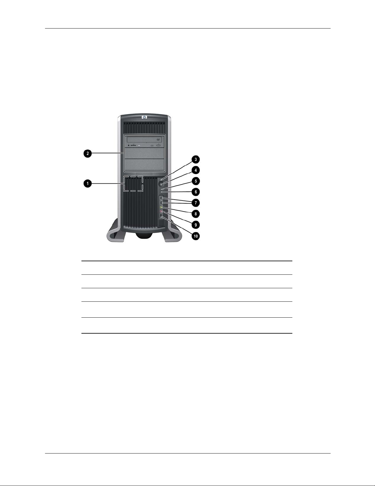
The HP workstation c8000 front panel has the features identified in the following figures.
■ A pull-out information card containing the product and serial numbers is on the side of the
system.
■ For more information about the system LEDs, see “LAN LEDs (Front and Rear Panel)” on
page 4-3.
Product Information
Front panel, tower configuration
1 System speaker 6 LAN activity LED
2 Three optical drive bays 7 Two USB connectors
3 System status LED 8 Headphone (option)
4 Power button
5 Disk activity LED
Microphone (option)
9
IEEE-1394 FireWire (not supported)
-
Technical Reference Guide 1–7
Page 16
Product Information
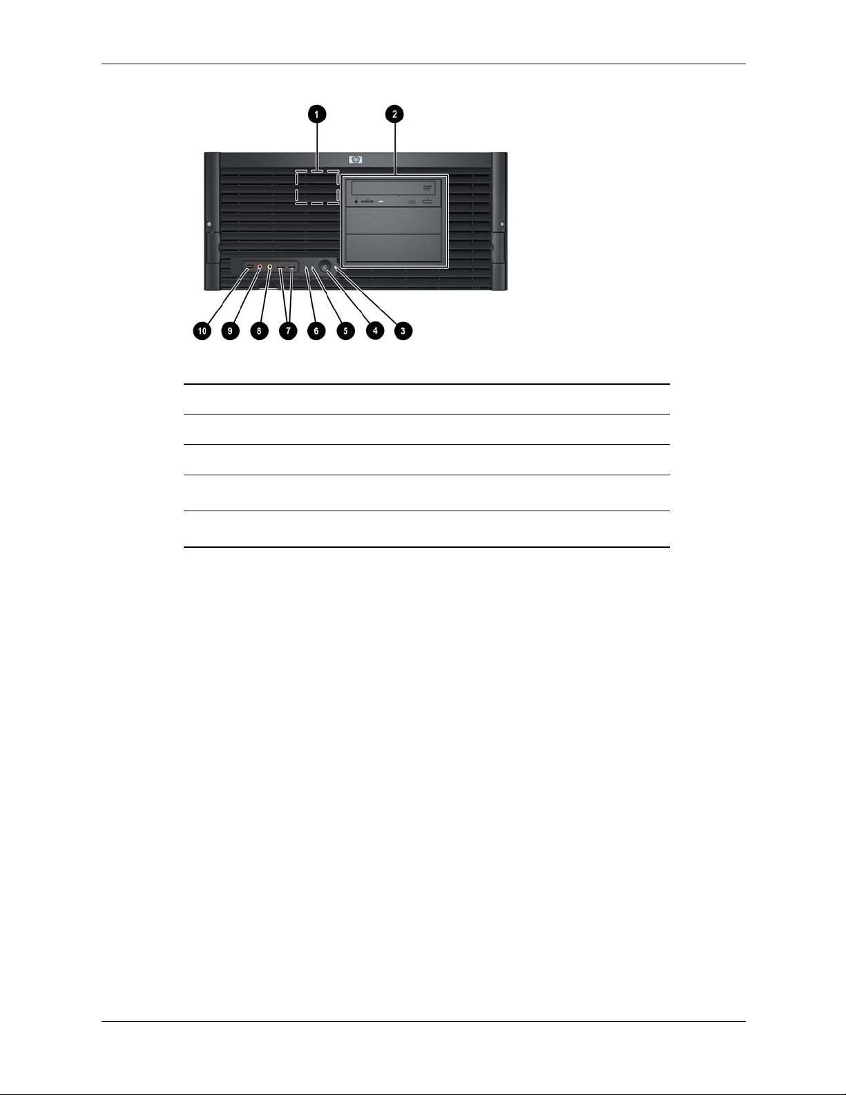
Front panel, rack-mount configuration
-
1 System speaker 6 LAN activity LED
2 Three optical drive bays 7 Two USB connectors
3 System status LED 8 Headphone (option)
4 Power button
5 Hard Disk activity LED
Microphone (option)
9
IEEE-1394 FireWire (not supported)
-
1–8 Technical Reference Guide
Page 17
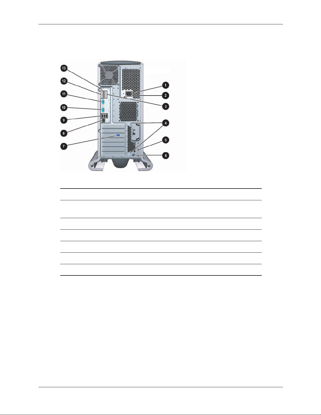
Rear Panel
The HP workstation c8000 rear panel has the following connectors and features:
Product Information
Rear panel, tower configuration
1 Power cord connector 8 LAN connector and LEDs
2 Built-In Self Test LED (power supply
9 Three USB connectors
LED behind ventilation holes)
3 On-board diagnostic LEDs - Serial connector B
4 PCI/AGP retention release ; Serial connector A
5 External SCSI connector (option) < Diagnostic LEDs
6 Security cable slot = Transfer-of-control (TOC) button
7 Monitor connector (on graphics card)
Technical Reference Guide 1–9
Page 18
Product Information
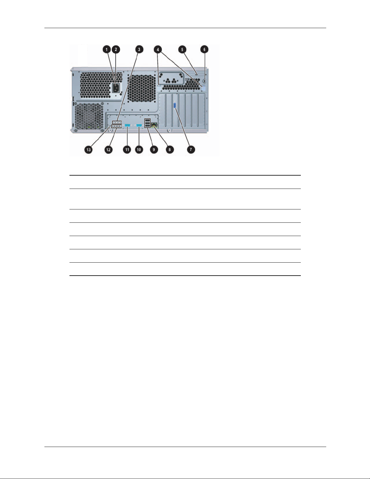
Rear panel, rack-mount configuration
1 Power cord connector 8 LAN connector and LEDs
2 Built-In Self Test LED (power supply
9 Three USB connectors
LED behind ventilation holes)
3 On-board diagnostic LEDs - Serial connector B
4 PCI/AGP retention release ; Serial connector A
5 External SCSI connector (option) < Diagnostic LEDs
6 Security cable slot = Transfer-of-control (TOC) button
7 Monitor connector (on graphics card)
1–10 Technical Reference Guide
Page 19

You will typically alter the system configuration only if you want to change the boot device or
change the console. This chapter covers:
■ “Boot Console Handler (BCH)” on page 2-1
■ “Firmware Upgrades” on page 2-9
Boot Console Handler (BCH)
You can configure the HP workstation c8000 system with The Boot Console Handler (BCH), the
user interface to the system firmware. The BCH:
■ Lets the bootstrap code know which path (that is, which device) to boot from.
■ Allows you to view and modify a set of specific system parameters.
■ If you are satisfied with your system configuration, you do not need to perform any system
configuration.
2
System Configuration
Accessing the BCH
You can access the BCH through either:
■ your system’s USB keyboard and graphics monitor by interrupting the normal boot process
■ a serial console connection and terminal emulator.
Access via Keyboard and Graphics Monitor
When you boot your system, the boot process pauses and gives you 10 seconds to interrupt the
normal boot process. Perform the specified action to access the BCH. When you are finished,
reboot your system.
Access via Serial Console Connection
To access the BCH through a serial connection:
1. With the workstation turned off, connect the serial cable provided with your system or a
compatible cable to Serial Port A on the rear panel of the workstation, and to your remote
device.
NOTE: If your system has a plug-in serial card (installed in slot 6), connect to the card’s serial
port instead of to Serial Port A.
2. Disconnect all USB keyboards from the system.
Technical Reference Guide 2–1
Page 20

System Configuration
3. Configure the terminal emulation software with these settings:
❏ Baud rate: 9600
❏ Bits: 8
❏ Parity: None
❏ Stop Bits: 1 (one)
❏ Flow Control: XON/XOFF
4. Using the terminal emulation software, connect to the workstation with a direct connection.
5. Turn on the workstation. The system display is redirected to the serial console device.
Paths
All devices in the HP workstation c8000 are represented by paths in the BCH. To identify the
correct slot or disk drive, use the following tables.
Accessory Card Slots
Slot Path
1 PCI (33 MHz, 32 bit, half-length) 0/3/5/0
2 PCI (33 MHz, 32 bit, half-length) 0/3/4/0
3 AGP 8X 32 bit 0/4/0/0
4 PCI (33 MHz, 64 bit) 0/3/6/0
5 PCI-X (66 MHz, 64 bit) 0/2/2/0
6 PCI-X (66 MHz, 64 bit) 0/2/3/0
7 PCI-X (133 MHz, 64 bit) 0/0/1/0
IDE Drives
Drive Path Hardware Connection
IDE hard drive 1 (or optical drive 3) 0/3/2/0.0.0 IDE 0, master
IDE hard drive 2 0/3/2/0.0.1 IDE 0, slave
IDE optical drive 1 0/3/2/0.1.0 IDE 1, master
IDE optical drive 2 0/3/2/0.1.1 IDE 1, slave
2–2 Technical Reference Guide
Page 21

SCSI Drives
Drive Path
SCSI hard drive on channel A 0/2/1/0.<scsi_ID>
SCSI hard drive on channel B 0/2/1/1.<scsi_ID>
Network
Device Path
Built-in LAN 0/3/3/0
System Configuration
Technical Reference Guide 2–3
Page 22

System Configuration
BCH Commands
The interactive portion of BCH includes the following five main commands, which are available
on the Main Menu and all submenus.
Command Description
BOot [PRI
DIsplay Redisplay the current menu
HElp [<menu>
RESET Restart the system
MAin Return to the Main Menu
Main Menu
The following commands are available in the main menu.
--- Main Menu ---------------------------------------------------------------
Command Description
------- -----------
BOot [PRI|ALT|<path>] Boot from specified path
PAth [PRI|ALT|CON|KEY] [<path>] Display or modify a path
SEArch [DIsplay|IPL] [<path>] Search for boot devices
COnfiguration menu Displays or sets boot values
INformation menu Displays hardware information
SERvice menu Displays service commands
DIsplay Redisplay the current menu
HElp [<menu>|<command>] Display help for menu or command
RESET Restart the system
|ALT|<path>] Boot from a specified path
|<command> Display help for menu or command
2–4 Technical Reference Guide
Page 23

System Configuration
Configuration Menu
The following commands are available in the configuration menu.
----------------------------------------------------------------------------------
Main Menu: Enter command or menu > co
--- Configuration Menu ------------------------------------------------------
Command Description
------- -----------
AUto [BOot|SEArch|STart] [ON|OFF] Display or set specified flag
BootID [<proc> [<bootid>]] Display or set Boot Identifier
BootINfo Display boot-related information
BootTimer [0 - 200] Seconds allowed for boot attempt
CPUconfig [<proc> [ON|OFF]] Config/Deconfig processor
DEfault Set the system to predefined values
FastBoot [ON|OFF] Display or set boot tests execution
LanConfig [<config type>] Display or set LAN configuration
MOnitor [LIST|<type>] Display or set the current monitor type
PAth [PRI|ALT|CON|KEY [<path>]] Display or change a path
PoWerRestore [ON|OFF|LAST] Display or set the Power Restore Policy
ResTart [ON|OFF] Display or set the System Restart Policy
SEArch [DIsplay|[[IPL] [<path>]]] Search for boot devices
SECure [ON|OFF] Set/show security mode
TIme [c:y:m:d:h:m[:s]] Read or set the real time clock in GMT
BOot [PRI|ALT|<path>] Boot from specified path
DIsplay Redisplay the current menu
HElp [<command>] Display help for specified command
RESET Restart the system
----------------------------------------------------------------------------------
The configuration default command sets the following values:
Primary boot path: scsiA.0 (core SCSI)0
Alternate boot path: lan.0.0.0.0 (core LAN)
Console path: graph3 (AGP Graphics Slot 3)
Keyboard path: usb0 (core USB)
Autoboot: ON
Autosearch: ON
Autostart: OFF
BootTimer 0
Technical Reference Guide 2–5
Page 24

System Configuration
Information Menu
The following commands are available from the information menu:
----------------------------------------------------------------------------------
Main Menu: Enter command or menu > in
---- Information Menu --------------------------------------------------------
Command Description
------- -----------
ALL Display all system information
BootINfo Display boot-related information
CAche Display cache information
ChipRevisions Display revisions of major VLSI
COprocessor Display coprocessor information
FRU Display FRU information
FwrVersion Display firmware version
* IO Display I/O interface information
LanAddress Display Core LAN station address
MEmory Display memory information
PRocessor Display processor information
** WArnings Display selftest warning messages
BOot [PRI|ALT|<path>] Boot from specified path
DIsplay Redisplay the current menu
HElp [<command>] Display help for specified command
RESET Restart the system
MAin Return to Main Menu
----------------------------------------------------------------------------------
* The PCI device information displayed includes Description, Path, VendorID, DeviceID,
Slot#, and bus#.
** Any warnings that apply are displayed.
2–6 Technical Reference Guide
Page 25

System Configuration
The Info PR command displays processor information on the console. For example:
----------------------------------------------------------------------------------
Main Menu: Enter command or menu > in pr
Model: hp workstation c8000 (model string 9000/785/c8000)
PROCESSOR INFORMATION
HVERSION SVERSION Processor
Processor Speed HVERSION SVERSION CVERSION Processor
--------- -------- -------- -------- -------- ---------0 1000 MHz 0x088b 0x0491 3.1 Active
1 1000 MHz 0x088b 0x0491 3.1 Idle
2 1000 MHz 0x088b 0x0491 3.1 Idle
3 1000 MHz 0x088b 0x0491 3.1 Idle
Central Bus Speed (in MHz) : 200
Software ID (dec) : 1704034802
Software ID (hex) : 0x659181f2
Software Capability : 0x01f0
----------------------------------------------------------------------------------
Model Model/Op State
Technical Reference Guide 2–7
Page 26

System Configuration
Service Menu
The following commands are available from the Service menu.
------------------------------------------------------------------------------------
Main Menu: Enter command or menu > ser
---- Service Menu ------------------------------------------------------------
Command Description
------- -----------
ChassisCodes [<proc>|ON|OFF] Display/enable/disable chassis codes
CLeaRLogs Clear SEL and FPL logs
CLEARPIM Clear (zero) the contents of PIM
MemRead <address> [<len>] Read memory and I/O locations
PDT [CLEAR] Display or clear the PDT
PIM [<proc>] [HPMC|LPMC|TOC]] Display PIM information
ScRoll [ON|OFF] Display or change scrolling ability
SCSI [<path> [<option> [<val>]]] Display or set SCSI controller values
SErial [ON|OFF] [A/B] Display/enable/disable core serial ports
------------------------------------------------------------------------------------
The SCSI command is for displaying/setting the SCSI controller parameters like initiator ID and
speed. These parameters are used by the OS device drivers to program the controller(s).
The serial port command automatically resets the system. When the serial ports are enabled, the
ports can be used with HP-UX.
NOTE: If the HP-UX version was released prior to June 2004, the system might not boot if the
✎
serial ports are enabled.
Baseboard Management Controller
The Baseboard Management Controller (BMC) supports the industry-standard Intelligent
Platform Management Interface (IPMI) specification. The management features have been built
into the system board and include diagnostics (local and remote), console support, configuration
management, hardware management, and troubleshooting.
2–8 Technical Reference Guide
Page 27

Firmware Upgrades
To update the system and BMC firmware:
System Configuration
1. Download the firmware update from
http://www.hp.com/bizsupport.
Follow the menu prompts to navigate to the support page:
a. Select
b. Enter the product name in the search field (
download drivers/software.
HP workstation c8000).
c. Select the search result.
d. Choose the firmware release you need to download.
e. Click the release notes for instructions on how to download, unpack, and install the
firmware upgrade.
2. Download, unpack, and install the firmware upgrade.
3. Execute the
in FwrVersion BCH command to confirm that the upgrade was successful.
Technical Reference Guide 2–9
Page 28

System Configuration
2–10 Technical Reference Guide
Page 29

Installing or Replacing Parts
This chapter contains the following sections:
■ Locating System Components, page 3-1
■ Tools and Safety, page 3-5
■ Removing and Replacing Access Panels, page 3-6
■ Removing and Replacing Internal Components, page 3-8
Locating System Components
This section contains diagrams to help you locate system components. The diagrams in this
section include only the most frequently accessed components and connectors. For
comprehensive component and system board diagrams, see the label on the inside of the main
access panel.
■ Location of Internal Components, page 3-2
■ Exploded View of Main System Components, page 3-3
3
■ System Board Components and Connectors, page 3-4
For the location of items on the front and rear panel of the system, see:
■ Front Panel, page 1-7
■ Rear Panel, page 1-9
Technical Reference Guide 3–1
Page 30
Installing or Replacing Parts
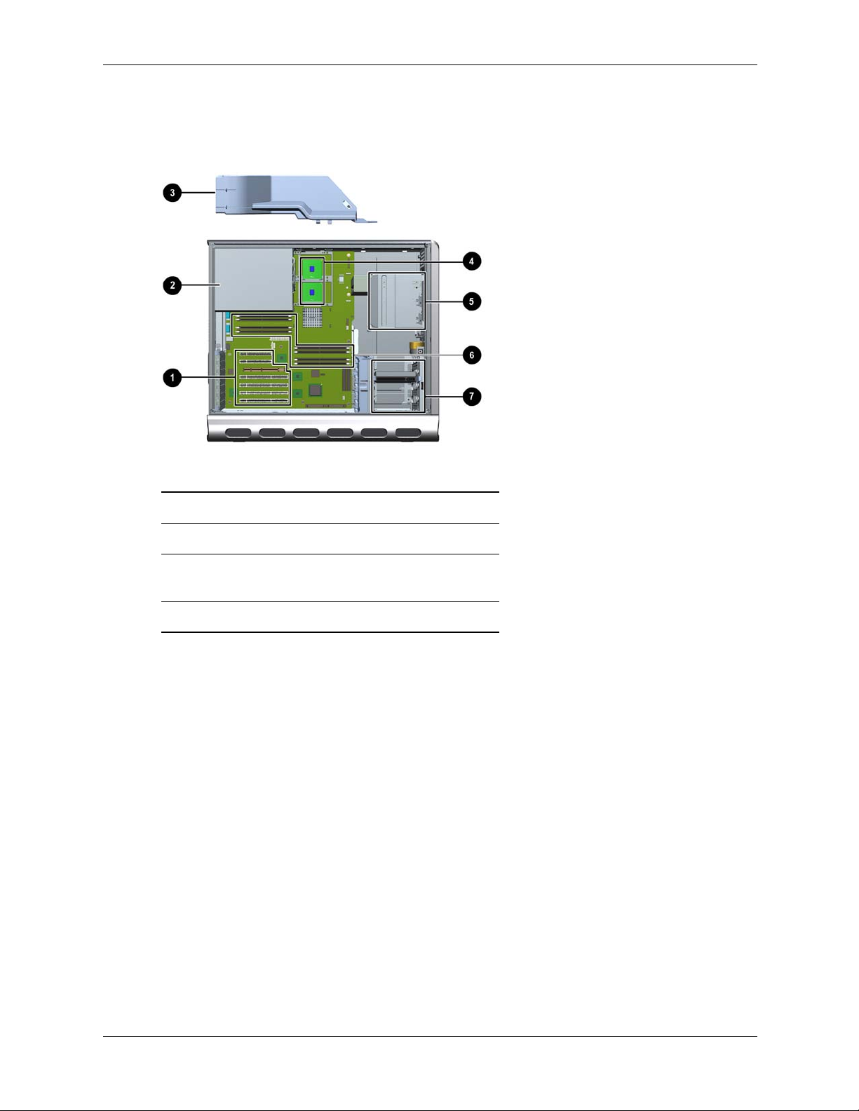
Location of Internal Components
This diagram identifies main system components. For a comprehensive component diagram, see
the label on the inside of the main access panel.
Location of internal components
1 PCI and AGP slots 5 Optical drive bays
2 Power supply 6 Memory slots
3 Air flow guide and
memory fan
4 CPU sockets
7 Hard drive bays
3–2 Technical Reference Guide
Page 31

Exploded View of Main System Components
This diagram identifies main system components. For a comprehensive component diagram, see
the label on the inside of the main access panel.
Installing or Replacing Parts
Exploded view of system components
1 Power supply : Hard drive fan
2 CPU0 and CPU1 with power modules ; AGP retainer
3 Chassis fan < System board
4 Airflow guide and memory fan = AGP graphics card
5 Top panel > Memory module
6 Optical drive ? Hard drive with rails
7 Chassis @ Front access panel (rack-mount)
8 Front access panel (tower) A Main (side) access panel
9 Pedestal
Technical Reference Guide 3–3
Page 32

Installing or Replacing Parts
System Board Components and Connectors
This diagram identifies main system board components and connectors. For a comprehensive
system board diagram, see the label on the inside of the main access panel.
System board connectors and slots
1 Slot 7 PCI-X connector
(133 MHz 64 Bit)
2 Slot 6 PCI-X connector
(66 MHz 64 Bit)
3 Slot 5 PCI-X connector
(66 MHz 64 Bit)
4 Slot 4 PCI connector
(33 MHz 64 Bit)
5 Slot 3 AGP Pro
8X connector
6 Slot 2 PCI connector
(half-length 33 MHz 32 Bit)
7 Slot 1 PCI connector
(half-length 33 MHz 32 Bit)
8 LAN connector 18 Processor power
9 Rear USB
connectors (3)
10 Serial B connector 20 Processor—CPU 0 30 Memory module
11 Serial A (console)
connector
12 Diagnostic LEDs 22 Processor fan
13 Transfer of Control
(TOC) button
14 On-board LEDs 24 Processor fan
15 Chassis fan connector 25 Front control panel
16 Input power
connector—CPU 1 (option)
17 Input power
connector—CPU 0
module—CPU 0
19 Processor power
module—CPU 1(option)
21 Processor—CPU 1 (option) 31 Primary IDE 0
connector—CPU 0
23 Battery connector 33 Front panel USB
connector—CPU 1
connector
26 Memory fan
connector
27 Main power
connector
28 Auxiliary power
connector
29 System board
tray release
connectors
connector
32 Secondary IDE 1
connector
connector
34 Hard drive fan
connector
35 SCSI A
connector
36 SCSI B
connector
Hard drive activity
LED connector
3–4 Technical Reference Guide
Page 33

Tools and Safety
Most hardware replacement tasks do not require any tools. However, to prevent possible damage
from static electricity, you will need:
■ Static-free mat
■ Static strap
These tasks require tools:
■ If you are adding or replacing a processor, you will need the special processor tool that is
provided with the new processor.
■ If you are removing or replacing the front control module, you will need a T-15 Torx driver.
WARNING: For hardware installation procedures, you must power off the system, unplug the power
Å
cord from the outlet, and wait for all LEDs to turn off.
WARNING: If you have any doubt that you can lift the system or monitor safely, do not try to move them
Å
without help.
NOTE: To maintain FCC/EMI (Electromagnetic Interference) compliance, replace all covers
and make sure all screws are properly seated after you replace components.
Installing or Replacing Parts
To prevent damage to this system, observe all of the following ESD precautions while
performing the system parts removal/replacement procedures:
■ Work on a static-free mat.
■ Wear a static strap to ensure that any accumulated electrostatic charge is discharged from
your body to ground.
■ Create a common ground for the equipment you are working on by connecting the static-free
mat, static strap and peripheral units to that piece of equipment.
■ Keep uninstalled printed circuit boards in their protective antistatic bags.
■ Handle printed circuit boards by their edges, once you have removed them from their
protective antistatic bags.
Technical Reference Guide 3–5
Page 34

Installing or Replacing Parts
Removing and Replacing Access Panels
To upgrade, remove or replace system components, you need to remove one or both access
panels from the system chassis.
WARNING: Never remove the system access panel(s) without first turning the system off and
Å
unplugging the power cord from the back of the system. Always replace the cover(s) before turning the
workstation on.
Removing the Main System Access Panel
To remove or install most components, you only need to remove the main system access panel.
NOTE: The front system access panel only needs to be removed when removing the “Front
✎
Control Module” on page 3-29 or the “Optical Drives (CD or DVD)” on page 3-17.
1. Unlock the panel if it is locked 1.
2. Pull out on the latch to release it 2.
3. Rotate the panel 3, pull up 4, and lift it away 5.
Removing the main system access panel
3–6 Technical Reference Guide
Page 35

Removing the Front Access Panel
To install or replace the “Front Control Module” on page 3-29 or the “Optical Drives (CD or
DVD)” on page 3-17, you need to remove the front access panel.
1. If you have already connected and turned on the system, turn off the system and disconnect
all cables.
2. Remove the main system access panel:
a. Unlock the panel if it is locked 1
b. Pull out on the latch to release it 2
c. Rotate the panel 3 and lift it off 4
3. Remove the front system access panel:
a. Depress the clips on the inside of the case to release the front panel 5
b. Rotate the panel and lift it off 6
Installing or Replacing Parts
Removing the system access panels
Technical Reference Guide 3–7
Page 36

Installing or Replacing Parts
Removing and Replacing Internal Components
This section includes instructions for removing and replacing the following components:
■ Airflow Guide and Memory Fan, page 3-9
■ Memory Modules, page 3-10
■ PCI and AGP Cards, page 3-12
■ Optical Drives (CD or DVD), page 3-17
■ Hard Drives, page 3-19
■ External SCSI Devices, page 3-23
■ Power Supply, page 3-25
■ Hard Drive and Chassis Fans, page 3-27
■ Front Control Module, page 3-29
■ Replacing the Processor or Installing an Additional Processor, page 3-32
■ System Board, page 3-39
■ System Battery, page 3-41
Instructions for the following procedures are included with kits containing the parts:
■ Processor Replacement and Installation
■ Tower-to-Rack Conversion
■ Rack-to-Tower Conversion
3–8 Technical Reference Guide
Page 37

Airflow Guide and Memory Fan
The system airflow guide and memory fan must be removed to access several other components.
To remove the airflow guide and fan:
1. Turn off the system, disconnect the power cable, and remove the system access panel.
2. Unplug the memory fan connector from the system board 1.
3. Grasp the airflow guide 2 and lift it out of the system 3.
Installing or Replacing Parts
Removing the airfllow guide and fan
To replace the airflow guide and fan:
1. Insert the airflow guide into the system and press until it snaps into place.
2. Plug the memory fan connector into the system board.
Technical Reference Guide 3–9
Page 38

Installing or Replacing Parts
Memory Modules
The HP workstation c8000 has eight memory slots for Dual Inline Memory Modules (DIMMs).
These modules can be:
■ 256 MB
■ 512 MB
■ 1 GB
■ 2 GB
■ 4 GB
DIMMs must be installed in matched pairs of equal size. You can install a minimum of 512 MB
and a maximum of 32 GB of memory.
■ To obtain detailed configuration information for your system, use the BCH Information
menu (see page 2-6).
■ For a list of approved memory modules, see:
http://partsurfer.hp.com
Removing Memory Modules
1. Turn off the system, disconnect all cables, and remove the main access panel and airflow
guide.
WARNING: To ensure that memory modules are not damaged during removal or installation, power off
Å
the workstation and unplug the power cord from the AC power outlet. Wait until the power supply LED
(page 1-7) turns off before removing or installing memory.
2. Press downward and outward on the memory module retainer clips, then lift the DIMM out
of the slot by its edges.
Removing DIMMs
3. If the removed memory is functional, store it in a static-free container for future use.
4. Replace the airflow guide and system access panel, reconnect all cables, and turn on the
system.
5. Check the configuration using the BCH
Information menu (page 2-6).
3–10 Technical Reference Guide
Page 39

Installing Memory Modules
1. Turn off and unplug the system, disconnect the power cable, and remove the system access
panel and airflow guide.
WARNING: To ensure that memory modules are not damaged during removal or installation, power off
Å
the workstation and unplug the power cord from the AC power outlet. Wait until all LEDs on the system
board turn off before removing or installing memory.
2. Holding the DIMM by its left and right edges, insert it into the slot. Make sure DIMMs are
inserted fully and that the side clips fully clasp the DIMM edges.
CAUTION: The memory modules are keyed and can only be inserted in one direction. Do not try to
Ä
force a DIMM into a slot backwards. When the module is correctly seated, the retainer clips will return to
their fully upright position. Snap the clips firmly into place to ensure that the DIMMs are seated properly.
3. Replace the airflow guide and system access panel, reconnect all cables, and turn on the
system.
Installing or Replacing Parts
4. Check the memory configuration using the BCH
DIMM Installation Guidelines
The HP workstation c8000 has eight memory DIMM slots organized as four a/b pairs: 0a and 0b,
1a and 1b, 2a and 2b, 3a and 3b.
❏ The DIMM in each a slot must match the DIMM in the corresponding b slot.
❏ DIMMs match if they have the same HP part number. (Two empty slots also match.)
❏ For maximum system performance, install DIMMs so that the even pairs match the odd
pairs: 0a and 0b match 1a and 1b; 2a and 2b match 3a and 3b.
❏ Matched pairs should be loaded in this order:
1 slots 0A and 0B
2 slots 1A and 1B
3 slots 2A and 2B
4 slots 3A and 3B
Information menu (page 2-6).
DIMM slots
Technical Reference Guide 3–11
Page 40

Installing or Replacing Parts
PCI and AGP Cards
This section explains how to:
■ access the AGP and PCI slots, and
■ remove and replace AGP graphics and PCI accessory cards.
Removing PCI or AGP Card
1. Turn off the system, disconnect all cables, and remove the main access panel.
2. Remove the AGP retainer if it is blocking the card you wish to access:
a. Press in on the release snaps on the AGP retainer 1.
b. Rotate the retainer outwards 2 and lift it out of the system.
Removing the AGP retainer
3–12 Technical Reference Guide
Page 41

Installing or Replacing Parts
3. Open the PCI/AGP retainer clip:
❏ Push in on the two blue levers at the ends of the PCI/AGP retainer clip 1 then rotate the
clip into the open position 2.
Opening the PCI/AGP retainer clip
4. Remove the card:
a. If the card is an audio card, unplug the connectors attached to the front control panel (see
figure on page 3-29).
b. If the card is a full length card, push the card edge stop to the side to allow the card to
slide out of the guide.
Full-length AGP or PCI card
Technical Reference Guide 3–13
Page 42

Installing or Replacing Parts
c. Grasp the card at the edges 1 and lift it out of the slot 2.
Removing an AGP or PCI card
5. If you are not installing a new card in the same slot, insert a filler blank. If you are installing
a new card in the same slot, see page 3-15.
6. Close the PCI/AGP retainer clip and press the two blue release snaps on the rear panel of the
system to lock it in place. (See figure on page 3-13).
7. Replace the AGP retainer if you removed it.
a. Insert the tab on the retainer securely into the slot on the rear edge of the system
chassis 1 and rotate the retainer until it snaps into place 2.
b. Make sure the retainer 3 is securely holding the AGP card in place.
Replacing the AGP retainer
8. Replace the main access panel, reattach the power cable and any external cables attached to
the PCI/AGP cards, and turn on the system.
3–14 Technical Reference Guide
Page 43

Installing or Replacing a PCI or AGP Card
NOTE: For specifications on your graphics card, visit the manufacturer’s web site or refer to the
graphics documentation included in the acccessory kit.
To install an accessory or graphics card:
1. Remove the existing card or bulkhead blank that is in the slot you want to use.
a. From the inside of the case, push on the two blue release snaps at the ends of the
PCI/AGP retainer clip 1 then rotate the clip into the open position 2.
b. If the slot has a card installed, remove it (page 3-12).
c. If the slot is empty, pull the filler blank out of the system 3.
Installing or Replacing Parts
Removing the existing card or bulkhead blank
Technical Reference Guide 3–15
Page 44

Installing or Replacing Parts
2. Install the card:
a. Grasp the edges of the new card and insert it into the slot.
b. If the card has a power connector, plug it in.
Plugging in a PCI or AGP card power connector
c. If the card is a full length card, the end of the card will automatically snap into place (not
shown).
3. Close the PCI/AGP retainer clip and press the two blue release snaps on the rear panel of the
system to lock it in place. (See the figure on page 3-13).
4. Replace the AGP retainer and system access panel and reconnect all cables.
5. Turn on the system and check the configuration using the BCH
Information menu
(page 2-6).
3–16 Technical Reference Guide
Page 45

Optical Drives (CD or DVD)
Removing an Optical Drive
1. Turn off the system, disconnect all cables, and remove the system access panel and front
panel.
2. Disconnect the audio 1, IDE 2, and power 3 cables from the optical drive.
3. Pull outward on the lever to release the optical drives from the bay 4.
Installing or Replacing Parts
Disconnecting an optical drive
4. Grasp the optical drive firmly and slide it forward to pull it out of the drive bay.
Removing an optical drive from tower and rack-mounted systems
5. If you are not replacing the optical drive with a new drive, install a blank in the drive bay
opening and a plastic filler in the front panel.
Technical Reference Guide 3–17
Page 46

Installing or Replacing Parts
Installing an Optical Drive
1. Turn off the system, disconnect all cables, and remove the system access panels.
2. Pull the release handle on the optical drive bay, and slide the optical drive into the bay until it
stops and snaps into place. Verify that the drive is properly installed by checking that the
small alignment holes on the side of the drive bay are aligned with the holes on the drive
(4 below).
If you need help performing these steps, refer to “Removing an Optical Drive” on page 3-17.
3. Connect the power and audio cables to the optical drive.
4. Connect the IDE cable to the optical drive:
The system has two IDE cables:
❏ If you have IDE hard drives installed, one cable is used to connect the hard drives, the
other to connect up to two optical drives.
❏ If you have SCSI hard drives installed, two optical drive IDE cables are available to
connect up to three optical drives.
To connect the IDE cable:
a. Locate the IDE cable(s) connected to the secondary IDE connector on the system
board 1 and route the cable(s) 2 to the optical drives. If you have three optical drives,
connect the third drive to the cable connected to the primary IDE connector.
b. Plug the cable in to the connector on the optical drive 3.
Connecting an optical drive
NOTE: The black connector on each cable is for the master device; the gray connector is for the
slave device. Make sure the jumper on the optical drive is set to cable select (CSEL), not to
master (M) or slave (S). See the documentation provided with your drive for help locating the
jumper.
3–18 Technical Reference Guide
Page 47

5. Replace the access panels and reconnect all cables.
Installing or Replacing Parts
6. Turn the system on, then check the configuration using the BCH
(page 2-6).
Hard Drives
Removing a Hard Drive
1. Turn off the system, disconnect all cables, and remove the system access panel.
2. Disconnect the hard drive IDE or SCSI cable 1 and power connector 2.
3. Squeeze inward on the blue release clips located on the sides of the drive 3. Then, pull
outward to remove the drive from the system 4.
Information menu
Removing a hard drive
Technical Reference Guide 3–19
Page 48

Installing or Replacing Parts
Replacing a Hard Drive
1. Review “Hard Drive Installation Guidelines” on page 3-21 for instructions on configuring
drives and installing drives in the correct bays.
2. Select a drive bay in which to install the drive. Squeeze inward on the blue release clips
located on the sides of the tray with attached drive rails. Pull forward to remove the tray from
the empty bay (see step 3 in figure of removing a drive on page 3-19).
3. Snap the drive inside the drive tray to attach rails to the hard drive. Pull outwards on the drive
rails 1, then place the tray onto the drive 2. Align the pins on the tray wtih the holes on the
drive and let the rails snap into place 3.
1
2
Attach the rails
4. Push the drive into the bay until it snaps into place 1. Then attach the power 2 and IDE or
SCSI cable 3 to the drive.
Installing a hard drive
5. Replace the system access panel and cables.
6. Turn the system on, then check the configuration using the BCH
Information menu
(page 2-6).
3–20 Technical Reference Guide
Page 49

Hard Drive Installation Guidelines
The system supports either IDE or SCSI hard drives, but not both in the same system.
IDE Drives
The HP workstation c8000 supports up to two IDE hard drives, attached to the primary IDE
cable.
NOTE: For additional information on configuring IDE drives, see Appendix A, “Ultra ATA /
IDE Guidelines.”
❏ The system has two IDE cables — one for connecting hard drives, and the other for
connecting optical drives. Locate the IDE cable connected to the primary IDE connector
on the system board 1 and attach the cable 2 to the hard drive.
❏ The black connector on each cable is for the master device 3; the gray connector is for
the slave device 4. Make sure the jumper on the hard drive is set to cable select (CSEL),
not to master (M) or slave (S). See the documentation provided with your drive for help
locating the jumper.
❏ Install the first drive in the top bay 3. Install the second drive in the bay above the
bottom bay 4.
Installing or Replacing Parts
IDE hard drive locations
NOTE: The Disk Activity LED automatically communicates with IDE and SCSI drives
connected to the built-in controllers.
To get this functionality with an SCSI or IDE controller card, connect the card with an LED
activity cable to the hard drive activity LED connector on the system board.
Refer to “System Board Components and Connectors” on page 3-4 for a picture showing where
on the system board to connect the LED activity cable (item 36).
Technical Reference Guide 3–21
Page 50

Installing or Replacing Parts
SCSI Drives
The HP workstation c8000 supports up to four SCSI hard drives attached to the SCSI A
connector.
1. Set the SCSI ID on your drive(s):
❏ Drive 1 ID=3
❏ Drive 2 ID=4
❏ Drive 3 ID=5
❏ Drive 4 ID=6
See the label on the hard drive or documentation provided with the drive for instructions on
setting SCSI IDs. These instructions should include a diagram of the jumper block and
jumper settings for each SCSI ID.
NOTE: See Appendix B, “SCSI Guidelines” for more information on configuring SCSI drives.
2. Locate the SCSI cable connected to the SCSI A connector on the system board 1 and attach
the cable 2 to the hard drive(s).
3. Install drives in bays in the following order 3:
❏ Use bay 3d for Drive 1
❏ Use bay 3b for Drive 2
❏ Use bay 3c for Drive 3
❏ Use bay 3a for Drive 4
NOTE: There is no need to terminate the SCSI chain. The supported SCSI cable includes an
attached hardware terminator.
SCSI hard drive locations
3–22 Technical Reference Guide
Page 51

NOTE: The Disk Activity LED automatically communicates with IDE and SCSI drives
connected to the built-in controllers.
To get this functionality with an SCSI or IDE controller card, connect the card with an LED
activity cable to the hard drive activity LED connector on the system board.
Refer to “System Board Components and Connectors” on page 3-4 for a picture showing where
on the system board to connect the LED activity cable (item 36).
External SCSI Devices
You can add an external SCSI connector (U320 SCSI port) to the on-board SCSI controller or to
an optional PCI SCSI controller card.
Note that:
■ You can connect up to 15 devices at any SCSI ID, except SCSI ID 7 which is used by the host
controller.
■ The bus should be terminated as normal if you use external devices. No termination is
necessary if there are no devices connected.
Installing or Replacing Parts
■ SCSI IDs are set by jumpering pins on the disk drive.
■ If you are adding a SCSI hard drive to your system, you may need to change the SCSI ID of
the new hard drive so that all SCSI devices have unique IDs. If two devices use ID 0, the
system will not boot.
■ If you are replacing a SCSI hard drive, you can use the SCSI ID number of the current hard
drive for the replacement hard drive.
To install the external connector:
1. Remove the knockout panel in the chassis using a regular screwdriver. Insert a flat-head
screwdriver into the rectangular hole and twist the metal until the panel comes out.
Remove knockout panel
Technical Reference Guide 3–23
Page 52

Installing or Replacing Parts
2. Plug the cable into the connector 1 and route as shown.
Installing external connector
3. Peel the release liner off of the pad on the cable and press the pad against the chassis wall 2
to secure.
4. Thread the jackscrews through the rear chassis wall and into the connector 3.
3–24 Technical Reference Guide
Page 53

Power Supply
Before replacing the power supply, you can use the Built-In Self-Test (BIST) feature to find out if
the power supply still works. Refer to Chapter 4, “Troubleshooting”, for more information.
Removing the Power Supply
1. Turn off the system, disconnect all cables, and remove the system access panel and airflow
guide.
2. Unplug the power supply power connectors from all components 1, including the:
❏ hard drives
❏ optical drives
❏ graphics card
❏ system board
NOTE: Use caution when lifting the power supply because there are cables below the power
supply (illustrated on the next page) that must be removed before completely removing the
power supply from the chassis.
3. Loosen the thumbscrew that secures the power supply to the rear panel 2.
Installing or Replacing Parts
4. While supporting the power supply weight with your hand 3, reach inside the system chassis
and pull the lever that locks the power supply in place 4.
5. Slide the power supply toward the front of the chassis 5 and toward the PCI slots 6, then lift
it out 7.
6. Unplug the power supply cables that connect to the power module(s) 8.
2
3
5
6
7
4
8
Removing the power supply
NOTE: For information on testing the power supply, refer to “Troubleshooting the Power
✎
Supply” on page 4-14.
Technical Reference Guide 3–25
Page 54

Installing or Replacing Parts
Replacing the Power Supply
1. Before inserting the power supply, reconnect the processor power module cable(s) from the
power supply to the power modules on the system board.
NOTE: The power cables connecting to the power modules are interchangeable. The cables are
different colors but all are designed for the same purpose.
2. Align the tabs on the power supply with the mounting holes on the system chassis.
3. Insert the new power supply into the system chassis. Push the power supply up and slide it
toward the back of the chassis until it snaps into place.
4. Tighten in the thumbscrew that secures the power supply to the rear panel.
5. Connect the remaining power supply power cables to all system components, including the
hard drives, optical drives and system board. Be sure the cables are routed properly, so they
do not block the airflow guide or interfere with the heatsinks on the processors.
3–26 Technical Reference Guide
Page 55

Hard Drive and Chassis Fans
In addition to the fan attached to the airflow guide (page 3-9), two cooling fans are mounted at
the front and rear of the system.
Removing the Hard Drive and Chassis Fans
1. Turn off the system, disconnect the power cable, and remove the system access panel and
airflow guide.
2. To remove the hard drive fan:
a. Unplug the fan power cable from the system board.
b. Push in on the snap on the side of the fan 1. Then rotate the fan towards the rear of the
chassis 2 and lift it out of the system 3.
Installing or Replacing Parts
Removing hard drive fan
Technical Reference Guide 3–27
Page 56

Installing or Replacing Parts
3. To remove the chassis fan:
a. Unplug the fan power cable 1.
b. Remove the push rivets holding the fan in place 2 then slide the fan towards the front of
the chassis and lift the fan out of the system 3.
Removing the chassis fan
Replacing the Hard Drive and Chassis Fans
1. Grasp the replacement fan module firmly and insert it into same location from which you
removed the old fan.
❏ If you are replacing the chassis fan, install the push rivets.
2. Re-attach the fan cable.
3. Replace the access panel and reconnect all cables.
4. Turn the system on, then check that the fans have been properly installed by verifying that
none of the Diagnostic LEDs on the rear panel of the system are lit.
3–28 Technical Reference Guide
Page 57

Front Control Module
The front control module contains these connectors and components:
■ Front-access USB connector
■ Microphone and headphone connectors (optional)
■ IEEE-1394 FireWire connector (not supported)
■ Power button
■ System status LED
■ Temperature sensor
■ Chassis intrusion switch
■ Disk activity LED
■ LAN activity LED
Removing the Front Control Module
1. Turn off the system, disconnect all cables, and remove the system access panels.
2. Disconnect the front control module cables.
Installing or Replacing Parts
Location of front control module cables and connections
1 Power 4 Audio (plugged into optional PCI card)
• Microphone (a)
• Headphone (b)
2 USB 5 Temperature sensor
3 Chassis speaker 6 Chassis intrusion switch
Technical Reference Guide 3–29
Page 58

Installing or Replacing Parts
3. Remove the chassis intrusion switch and temperature sensor:
a. Slide the switch out of the slot by pushing it in the direction shown 1.
b. Pull the switch out of the opening 2.
c. Pull up on the head of the plastic push rivet and remove it, then remove the sensor from
the system 5.
Removing the chassis intrusion switch
4. Remove the panel from the system:
a. Use a Torx T-15 or slot screwdriver to remove the screws holding the front control
module in place 1 2 3.
Unscrewing the front control module
3–30 Technical Reference Guide
Page 59

b. Remove the module, carefully extracting the attached cables through the opening on the
chassis.
Disconnecting the front control module
Replacing the Front Control Module
1. Insert the cables connected to the module through the opening in the system chassis and
route them to the appropriate connectors.
Installing or Replacing Parts
2. Reconnect the chassis intrusion switch:
a. Insert the new switch housing into the system chassis.
b. Insert the switch into the housing and slide in until it snaps into place.
3. Replace the temperature sensor and attach it with a plastic push rivet.
4. Replace the I/O panel in the system and use a Torx T-15 or slot screwdriver to attach the
mounting screws.
Replacing the front control module
5. Route the cables attached to the module to the appropriate components and connectors and
reconnect all cables (page 3-29).
6. Replace the system access panels and reconnect all power cables and turn on the system.
Verify that the System Status LED is working.
Technical Reference Guide 3–31
Page 60

Installing or Replacing Parts
Replacing the Processor or Installing an Additional Processor
To replace an existing processor or install a new one in the HP workstation c8000, follow these
steps.
Read Cautions and Warnings
For your safety, you must read the “Important Safety Warnings” at the beginning of this guide
and the “Tools and Safety” section at the beginning of this chapter before proceeding.
Remove the System Access Panel
1. Turn off the system and disconnect the power cable.
2. Place the unit on its side with the pedestal hanging over the edge of a table.
3. Remove the access panel (page 3-8).
Remove the Airflow Guide
1. Unplug the memory fan connector from the system board 1.
2. Grasp the airflow guide 2 and lift it out of the system 3.
Removing the airflow guide and fan
Remove the Power Supply
Follow the steps in “Removing the Power Supply” on page 3-25 to remove the power supply.
3–32 Technical Reference Guide
Page 61

Remove the Processor (for Replacement)
CAUTION: You must follow these steps exactly and in the correct sequence to avoid serious
Ä
damage to the system.
1. Remove the processor power module (CPU0 is shown):
a. Use the special processor tool (included with your processor kit) to remove the two
screws 1 from the processor power module.
b. Slide the processor power module towards the rear of the system until it stops, then lift it
out of the system.
Installing or Replacing Parts
Removing a processor power module
Technical Reference Guide 3–33
Page 62

Installing or Replacing Parts
2. Remove the processor:
a. Using the Torx driver end of the special processor tool, loosen the four screws on the
processor assembly until they pop up into the released position 1.
b. Insert the other end of the special processor tool into the slot on the side of the heatsink
and rotate the processor locking mechanism 180 degrees counter-clockwise to unlock
it 2.
Removing the processor
3. Lift the processor out of the system.
3–34 Technical Reference Guide
Page 63

Install the Processor
1. Prepare the CPU socket:
a. If you are adding a second CPU, remove the plastic film covering the socket.
b. Verify that the CPU locking mechanism is in the unlocked position.
Verifying unlocked position
Installing or Replacing Parts
The special processor tool rotates this lock
1
Unlocked
2
3 Locked
Technical Reference Guide 3–35
Page 64

Installing or Replacing Parts
2. Install the processor power module and the CPU:
a. Insert the processor into the socket.
b. Insert the allen wrench end of the special processor tool into the hole that runs down the
side of the heatsink. Engage the socket 1, and rotate it clockwise 180 degrees to lock the
processor in place. Remove the tool.
c. Using the other end of the special processor tool, tighten the four screws on the processor
assembly 2.
NOTE: If you are installing a new additional processor, the second power module shown in the
figure below will not be present.
Using the special processor tool
CAUTION: While carefully holding the system board back against the rear of the chassis, screw
Ä
in the four processor screws slowly, making sure to tighten all the screws evenly. Tighten one pair
of diagonally opposite screws 1 until the screw shank settles on the system board, then tighten
the remaining pair 2. Do not fully tighten one screw, then move on to the next. Tighten all of the
screws a little at a time, making sure the processor remains level.
3–36 Technical Reference Guide
Page 65

d. Insert the shims provided with the kit 1.
Installing or Replacing Parts
e. Insert the processor power module into the system
2 and slide it into the processor until
it stops.
f. Tighten the two screws from the processor power module firmly using the special
processor tool provided with the new processor 3.
Installing the processor power module
g. Plug in the fan connector 1.
1
Connecting fan connector
3. Replace the power supply (see “Replacing the Power Supply” on page 3-26) and reconnect
all power cables.
Technical Reference Guide 3–37
Page 66

Installing or Replacing Parts
Replace the Power Supply
Using the figure on page 3-34 as a guide:
1. Before inserting the power supply, be sure to re-connect the two processor power module
cables (from the power supply) to the power modules (on the system board).
2. Align the tabs on the power supply with the mounting holes on the system chassis.
3. Insert the new power supply into the system chassis. Push the power supply up and slide it
towards the back of the chassis until it snaps into place.
4. Connect the remaining power supply power cables to all system components, including the
hard drive(s), optical drive(s) and system board. Make sure the cables are routed properly, so
they do not block the airflow guide or interfere with the heatsinks on the processors.
Replace the Airflow Guide
Using the figure on page 3-38 as a guide:
1. Insert the airflow guide into the system and press until it snaps into place.
2. Plug the memory fan connector into the system board.
Replace the System Access Panel
Using the figure on page 3-8 as a guide:
1. Replace the system access panel.
2. Plug in the power cable and start the system to verify that it boots properly with the new
processor.
3–38 Technical Reference Guide
Page 67

System Board
Removing the System Board
1. Turn off the system, disconnect all external cables, and remove the system access panel.
Disconnect all devices attached to the system. Place the system on its side.
2. Disconnect the system board connectors (page 3-4) and remove all components except the
CPU(s).
❏ Power supply and all power cables connected to system board
❏ Airflow guide and memory fan
❏ Hard drive fan
❏ DIMMs
❏ AGP retainer
❏ Accessory and graphics cards
NOTE: Disconnect IDE and SCSI cables from the system board. Leave them attached to the
hard drives and optical drives.
Installing or Replacing Parts
3. Pull up on the lever on the optical drive cage (see figure on page 3-17, 4) and slide the
optical drives forward until the rear edge of the drives is aligned with the rear edge of the
drive cage.
4. Depress the lever on the edge of the system board to release it from the chassis 1.
5. Slide the system board toward the front of the system 2.
6. Lift up the edge of the system board and lift it out of the chassis
3.
Removing the system board
Technical Reference Guide 3–39
Page 68

Installing or Replacing Parts
Replacing the System Board
1. Complete all of the steps in the section “Removing the System Board” on page 3-39.
2. Grasp the new system board by its edges and carefully place it in the system. Remember that
the system board keyholes must be aligned with their corresponding standoffs on the
system’s chassis 1. Once the system board is in the system aligned with the keyhole
standoffs, rotate it into place 2 and slide it back toward the rear of the system until it snaps
into place 3.
Replacing the system board
3. Connect the system board cables and replace all components on the system board
(page 3-39).
4. Slide the optical drives back into place.
5. Replace the system access panel and reconnect the cables.
6. Start the system. If the system does not boot up properly, see Chapter 4, “Troubleshooting.”
7. Use the
ss_update utility (in the BCH Service menu) to reset the serial number.
3–40 Technical Reference Guide
Page 69

System Battery
Removing the System Board Battery
1. Turn off the system, disconnect all cables, and remove the system access panel.
2. Carefully pull the retainer clip away from the battery. Then rotate and lift 1 the battery out of
its holder.
CAUTION: Lift the battery just high enough to clear its holder. Too much stress on the retainer clip can
Ä
break it.
Installing or Replacing Parts
Removing the system battery
Replacing the System Board Battery
1. Slide the battery into the battery holder. The negative side should be facing out. Look at the
above image for correct battery orientation.
2. Replace the system access panel and reconnect all cables.
3. To verify that the battery has been installed correctly, check the time and date settings using
the BCH
You may need to reset the system time and date. Once you have set the time, turn the system
off, unplug the power cord, and wait for a minute before turning it back on. Execute the
time command again. If the time and date are now correct, you have installed the battery
correctly.
Time command (page 2-4).
Technical Reference Guide 3–41
Page 70

Installing or Replacing Parts
3–42 Technical Reference Guide
Page 71

4
Troubleshooting
This chapter describes how to identify and solve common problems you may encounter when
using your HP workstation c8000:
■ E-Support, page 4-2
■ Troubleshooting Overview, page 4-2
■ Identifying and Diagnosing Hardware Problems, page 4-2
■ BCH Error and Warning Messages, page 4-12
■ Troubleshooting the Power Supply, page 4-14
For online access to technical support information and tools, go to:
http://www.hp.com/bizsupport
Support resources include web-based troubleshooting tools, technical knowledge databases,
driver and patch downloads, online communities, and proactive notification services.
Technical Reference Guide 4–1
Page 72

Troubleshooting
E-Support
For online access to technical support information and tools, go to:
http://www.hp.com/bizsupport
Support resources include Web-based troubleshooting tools, technical knowledge databases,
driver and patch downloads, online communities, and proactive notification services.
Troubleshooting Overview
The HP workstation c8000 includes several tools to help you troubleshoot potential problems.
Many problems have simple solutions, so try the tools and suggestions covered in this section
before contacting HP support. The following sections provide additional information about:
■ Identifying and diagnosing hardware problems
■ Monitor troubleshooting
■ System logs and error messages
Identifying and Diagnosing Hardware Problems
For basic troubleshooting tips, see the HP workstation c8000 Getting Started Guide. If you need
further help with a hardware failure, the system LEDs and logs will help you identify the
problem:
■ LEDs. The lights on the front and rear panels of the workstation change color and blink in
different patterns to help identify specific hardware problems.
❏ LAN Activity LEDs
❏ Hard Disk Activity LED
❏ System Status and Diagnostic LEDs
❏ System Board LED
■ The BCH Error and Warning Messages provide additional detailed information about
errors identified by the LEDs.
If the LEDs and log files do not provide enough information for you to identify the problem you
are experiencing, HP also provides software diagnostic tools.
NOTE: See Chapter 2, “System Configuration” for detailed instructions on removing and
replacing system components.
4–2 Technical Reference Guide
Page 73

LEDs
Several LEDs are on the front and rear panels of the workstation (see figures on page 1-7 and
page 1-9). See the following sections for a detailed description of these functions.
LAN LEDs (Front and Rear Panel)
The LAN Activity LED on the front panel of the system blinks green when LAN activity is
present.
The two LAN LEDs on the LAN connector on the rear panel provide additional information
about LAN connection and activity.
LAN LED Location Color State
1. Activity Tower: Right Off No LAN connection
Rack-mounted: Top Yellow Link established
2. Speed Tower: Left Off 10Mbps
Troubleshooting
Blinking Activity on LAN port
Disk Activity LED
The Disk Activity LED on the front panel indicates the state of disk and drive activity on the
system.
Disk Activity LED State
Off Off or no current disk/drive activity
Blinking (green) Disk/drive is being accessed
NOTE: The Disk Activity LED automatically communicates with IDE and SCSI drives
connected to the built-in controllers.
To get this functionality with an SCSI or IDE controller card, connect the card with an LED
activity cable to the hard drive activity LED connector on the system board.
Refer to “System Board Components and Connectors” on page 3-4 for a picture showing where
on the system board to connect the LED activity cable (item 36).
Rack-mounted: Bottom Orange 100Mbps
Green Link at 1000Mbps
Technical Reference Guide 4–3
Page 74

Troubleshooting
System and Diagnostic LEDs
The System Status LED on the front panel of the system and the four Diagnostic LEDs on the
rear panel of the system are used for diagnosing the health of the system (see figures on page 1-7
and page 1-9). These LEDs warn of impending hardware failures and allow you to take
preventive action, such as making a system backup or replacing a component before it fails. The
Diagnostic LEDs are labeled 1, 2, 3 and 4 on the rear panel.
The location of red LEDs can be used to identify the category of the fault or warning. For
example, if LED one is red, there is a problem with memory. However, if LEDs one and two are
both red, there is a problem with the system processor.
The following symbols are used in the LED tables.
■ The System Status LED on the front panel of the system indicates the state of the
system:
Off indicates the system is off.
Green indicates that the system is running normally. Blinking green
indicates that the system is booting (slow blink 0.5Hz).
Blinking orange indicates a WARNING (medium blink 1.0Hz).
Blinking red indicates a FAULT (fast blink 1.5Hz).
■ The Diagnostic LEDs on the rear panel of the system provide details about each
specific warning or fault:
Solid red indicates the failing part or sub-system.
Off or solid green diagnostic LEDs provide additional details about the
failure (see page 4-6 and page 4-8).
4–4 Technical Reference Guide
Page 75

Troubleshooting
Fault and Warning Categories
The faults and warnings fall into the following general categories, each specific error is described
in detail on the following pages.
LED1 LED2 LED3 LED4 Category
Memory
Firmware
System Board
Fan
Processor
BMC
System
Temperature
Power
Unknown
Technical Reference Guide 4–5
Page 76

Troubleshooting
Warnings (System LED is Blinking Orange)
LED1 LED2 LED3 LED4 Warning Solution
Unknown Warnings
Memory Warnings
The following tables provide additional information about each specific warning
associated with the various possible Diagnostic LED lighting sequences when the
system LED is orange (medium blink 1.0Hz).
Unknown warning. Contact your HP Support
Engineer.
System Board Warnings
Mismatched memory
pairs.
Memory load order
error.
Can’t detect memory
type.
Battery voltage low. Replace the system board
Use the memory sequence
diagram in “Installing
Memory Modules” on
page 3-11.
Use the memory sequence
diagram in “Installing
Memory Modules” on
page 3-11.
Contact your HP Support
Engineer.
battery.
4–6 Technical Reference Guide
Page 77

LED1 LED2 LED3 LED4 Warning Solution
Fan Warnings
Troubleshooting
Processor Warning
Chassis fan not
functioning properly.
CPU0 cooling fan not
functioning properly.
CPU1 cooling fan not
functioning properly.
Memory fan not
functioning properly.
PCI/disk fan not
functioning properly.
Replace the fan that is not
functioning. If a processor
fan has failed, you must
replace the CPU.
Temperature Warning
Video Warning
CPU0 temperature
exceeds limit.
CPU1 temperature
exceeds limit.
External air
temperature too high.
No video adapter
present.
If the processor fan has
failed, you must replace the
CPU.
Make sure nothing is
blocking the system’s
airflow and locate your
system in an
air-conditioned room.
Install a video adapter. See
the installation instructions
shipped with the video
adapter.
Technical Reference Guide 4–7
Page 78

Troubleshooting
Faults (System LED is Blinking Red)
LED1 LED2 LED3 LED4 Fault Solution
Unknown Faults
Memory Faults
The following tables provide additional information about each specific fault
associated with the various possible Diagnostic LED lighting sequences when the
system LED is red (fast blink 1.5Hz).
Unknown fault. Contact your HP Support
Engineer.
Firmware Fault
Mismatched memory
pairs.
Uncorrectable memory
error.
No memory installed. Install memory in matched
Bad memory. One or
more DIMMs are bad
or not seated properly.
System firmware hang. Contact your HP Support
Use the memory
sequence diagram in
“Installing Memory
Modules” on page 3-11.
Replace memory.
pairs (see “Installing
Memory Modules” on
page 3-11).
Reseat the DIMMs. If the
error persists, replace
them.
Engineer.
4–8 Technical Reference Guide
Page 79

LED1 LED2 LED3 LED4 Fault Solution
System Board Fault
VRM undervoltage. Contact your HP Support
Engineer.
VRM overvoltage.
Unknown system board
fault.
System Fault
Machine check. The system resets due to a
problem. If you cannot
determine the reason for
the reset, contact your HP
Support Engineer.
Troubleshooting
Cooling Unit Faults
Chassis or CPU fan(s)
not functioning
properly.
Memory fan not
functioning properly.
PCI/disk fan not
functioning properly.
Replace the fan that is not
functioning. If the
processor fan has failed,
you must replace the
CPU.
Technical Reference Guide 4–9
Page 80

Troubleshooting
LED1 LED2 LED3 LED4 Fault Solution
Processor Faults
BMC Faults
CPU0 temperature
exceeds limit.
If the processor fan has
failed, you must replace
the CPU.
CPU1 temperature
exceeds limit.
No processor detected. Replace the CPU(s).
BMC firmware is
damaged.
System board FRU
inventory device
Reflash the BMC
firmware.
Replace the system
board.
inaccessible.
Temperature Faults
External air temperature
too high.
Make sure nothing is
blocking the system’s
airflow and locate your
system in an
air-conditioned room.
4–10 Technical Reference Guide
Page 81

LED1 LED2 LED3 LED4 Fault Solution
Power Faults
Troubleshooting
System Board LEDs
There are three additional LEDs that can help when troubleshooting the system. These LEDs are
located on the system board close to the back of the system and can be viewed through the small
holes in the system case just above the Diagnostic LEDs. See “Rear Panel” on page 1-9.
LED Description
1 STBY This standby LED comes on as soon as the system power cord is plugged in.
CPU 0 Power Module
fault.
CPU 1 Power Module
fault.
Power Supply fault. Replace the power
If this LED is off when you plug the system in, check that the power cord is
connected to the system and the outlet, and make sure the outlet is turned
on. If this does not work, make sure the main and auxiliary cables are
correctly plugged into the board. If the system is still not receiving power,
test the power supply following the instructions in “Troubleshooting the
Power Supply” on page 4-14. If you need to replace the power supply, refer
to “Power Supply” on page 3-25.
Contact your HP Support
Engineer.
supply.
2 BMC A few seconds after the system is plugged in this LED starts blinking, which
means that the Baseboard Management Controller is alive. If this LED is not
blinking and the STBY (standby) LED is on, you may have to replace the
system board.
3 F/W A few seconds after the power button is pressed in the system firmware
code fetch LED comes on indicating that the firmware has started the boot
process. If this LED does not come on, make sure:
• the processor(s) are correctly seated
• each processor power module is correctly mounted and connected to
the corresponding power supply cable
• all appropriate power supply cables are properly connected to the
system board
Technical Reference Guide 4–11
Page 82

Troubleshooting
BCH Error and Warning Messages
BCH error and warning messages are displayed on the console as part of the boot process. They
can also be retrieved via the
Warnings and errors displayed are:
WARNING: Processors are not installed in the correct order.
WARNING: Setting DEFAULTS has failed.
WARNING: Not enough error-free contiguous memory (GoodMem).
WARNING: Memory page deallocation has been disabled because the Page Deallocation
Table (PDT) is full.
ERROR: Current loading of DIMMs failed the loading order check.
WARNING: The Page Deallocation Table (PDT) is FULL.
WARNING: The system serial number is invalid.
ERROR: The BMC BT interface has failed on this system, Halt Boot.
WARNING: The BMC System Event Log (SEL) is full.
ERROR: The BMC BT port has failed on this system and an alternate BMC port is
being used as a failover.
WArnings BCH command.
WARNING: No graphics or serial consoles were found on this system.
WARNING: No usable graphics console was found on this system.The console has
defaulted to a serial port.
Displaying PIM Information
The pim command allows you to display the most recent PIM information for the specified fault
type. To display PIM information for a specific fault, execute the following from the Service
Menu:
pim
.
<processor_number> <fault_type>
Clearing the FPL and SEL Logs
The BMC clearlogs command in the Service submenu empties the log files.
NOTE: IF the SEL logs are full, a warning will be displayed when the system boots. Capture the
log contents be captured and archive them before clearing the logs if the system is experiencing
problems. HP support representatives may need the information from these files.
4–12 Technical Reference Guide
Page 83

Troubleshooting the VGA Monitor
It is normal for the display to remain blank for a minute or longer during system boot-up.
Direct the system output to a console device for troubleshooting:
1. With the workstation turned off, connect a 9-pin to 9-pin serial cable (HP F1044-80002) to
Serial Port A on the rear panel of the workstation, and to a laptop or other device with
terminal emulation software.
NOTE: If your system has a plug-in serial card (installed in slot 6), connect to the card’s serial
port instead of to Serial Port A.
2. Configure the terminal emulation software with these settings:
❏ Terminal emulation: VT100+
❏ Wrap lines: Off (unchecked)
❏ Baud rate: 9600
❏ Bits: 8
❏ Parity: None
Troubleshooting
❏ Stop Bits: 1 (one)
❏ Flow Control: XON/XOFF
3. Using the terminal emulation software, connect to the workstation with a direct connection.
4. Turn on the workstation.
Technical Reference Guide 4–13
Page 84

Troubleshooting
Troubleshooting the Power Supply
Before replacing the power supply, you can use the Built-In Self-Test (BIST) feature to find out if
the power supply still works.
To test the power supply:
1. Disconnect all internal power supply cables.
2. Plug the power supply plug into a working electrical wall outlet.
3. On the rear panel of the workstation, look through the ventilation holes above the power cord
connector for a green LED light. If the light is visible, the power supply is functional.
Refer to Chapter 1, in the “Rear Panel” section, for a picture showing where the LED is
displayed.
4–14 Technical Reference Guide
Page 85

Running HP Diagnostics
This section includes information on the Offline Diagnostics Environment (ODE) CD. These
tools may be used to diagnose hardware-related problems on your HP system.
NOTE: References to the SupportPlus Media in the SupportPlus User’s Guide, Chapter 3, should
be ignored: they do not apply to c8000 systems. However, the conceptual and procedural
information still applies to IPF systems. Any discrepancies have been noted and explained in the
SupportPlus User's Guide, and elsewhere, as appropriate.
Before you run the HP diagnostic software, note any LED error messages. They give you an
indication of the Field Replaceable Unit (FRU) to replace.
Offline Diagnostics Environment (ODE)
The Offline Diagnostics Environment is an offline support tools platform that enables users to
troubleshoot a system that cannot be tested using online tools. The offline environment is also
useful for some types of testing in which it is not desirable to have to boot the system first.
Tools Provided
The ODE includes a variety of diagnostics tools. Depending on your system and configuration,
these may include some or all of the following tools, as well as additional tools specific to your
system:
Troubleshooting
■ MAPPER2 is an offline system configuration mapping utility. It identifies and displays a list
of system components including hardware modules and peripheral devices.
■ MAKODIAG is a CPU diagnostics tool.
■ MEM2 is a memory diagnostics tool.
To access a detailed list of tools provided on your system, from the ODE Main Menu:
1. Select
View Release Notes and Documentation Menu.
2. Browse the documentation and release notes.
Running ODE from the Offline Diagnostics Environment CD
ODE uses a command line interface, which allows the user to select specific tests and/or utilities
to execute on a specific hardware module.
To run ODE from the HP Offline Diagnostics Environment CD:
1. Insert the CD into the CD/DVD drive and reset system power, the system should come up to
the boot manager.
2. If the boot manager is already configured, and the CD/DVD drive is configured as one of the
boot devices, move the cursor to the line which shows the CD/DVD drive, and press
Enter.
The CD then will boot to the Launch Menu.
3. Select
Run the Off-line Diagnostic Environment (ODE) from the launch menu.
NOTE: If you are unable to boot from your CD/DVD drive, restart your system and check the
boot options from the
Boot Options Maintenance Menu to ensure that your system is
configured to boot from the CD/DVD drive.
Technical Reference Guide 4–15
Page 86

Troubleshooting
For further information, see http://docs.hp.com/hpux/diag under the section titled
“Offline Diagnostics.” This site includes links to an FAQ, a conceptual overview, and a quick
reference guide to ODE. Also see the section titled “Diagnostics (Support Tools) General,”
especially the SupportPlus: Diagnostic User's Guide, Chapter 3. “Using the SupportPlus Media
to Run Offline Diagnostics” is a useful chapter for more information on what ODE is, and how to
run it.
4–16 Technical Reference Guide
Page 87

Resetting the BMC Password
To reset the BMC password:
1. Shut down the operating system and then turn off the workstation and any external devices.
Disconnect the power cord of the workstation and any external devices from the power
outlets.
2. Disconnect the keyboard, monitor, and any other external devices that are connected to the
workstation.
WARNING: To reduce the risk of personal injury from electrical shock and hot surfaces, be sure to
Å
disconnect the power cord from the wall outlet and allow the internal system components to cool before
touching.
CAUTION: When the workstation is plugged in, the power supply always has voltage applied to the
Ä
system board even when the unit is turned off. Failure to disconnect the power cord can result in damage
to the system.
CAUTION: Static electricity can damage the electronic components of the workstation or optional
Ä
equipment. Before beginning these procedures, be sure that you are discharged of static electricity by
briefly touching a grounded metal object.
Troubleshooting
3. Remove the access panel.
4. Remove the airflow guide and disconnect the memory fan.
5. Remove the power supply.
6. Locate the password header at J25, which is located at the edge of the system board between
the chassis fan connector and the input power connector (CPU 0).
7. Place a jumper on pins 7 and 8 (connecting both pins together). You must provide your own
jumper.
7
8
8. Reinstall the power supply.
9. Plug in the workstation and wait for the BMC heartbeat LED to start blinking green. There is
about a 5-second delay before the LED begins to blink green.
10. Unplug the AC power cord and remove the jumper.
11. Replace the access panel.
12. Plug in the AC power cord and boot the system. The passwords are cleared.
NOTE: The password jumper only has to be installed for a few seconds while AC power is
✎
connected (system power does not have to be on). The BMC logs an event in the SEL when the
jumper is set.
Technical Reference Guide 4–17
Page 88

Troubleshooting
4–18 Technical Reference Guide
Page 89

Ultra ATA Jumpers
Ultra ATA drives are configured by means of jumper settings. Factory-installed drives ship with
the jumpers preset to the cable-select mode; therefore, no jumper setting changes are required on
factory pre-installed, replacement, or option drives. With cable-select, the drive is configured as
either Master (Drive/Device 0) or Slave (Drive/Device 1) by its physical attachment to the cable.
If you purchase a third-party hard drive, refer to the documentation included with the drive kit to
ensure proper cable installation and configuration.
NOTE: All drives on a controller channel need to have their jumpers either in the cable-select
mode or have the individual drive jumper installed on the appropriate Master (Drive/Device 0) or
Slave (Drive/Device 1) position.
Ultra ATA Cables
A
Ultra ATA / IDE Guidelines
Drives operating at speeds faster than those of the Ultra ATA-33 require an industry standard
40-pin, 80-conductor Ultra ATA cable for optimal performance. These cables have a maximum
length of 18 inches and a maximum distance of 6 inches between the two devices for a two-drive
cable. These cables maintain the higher data transfer rates possible with the improved
technology.
When using Ultra ATA-133, -100, -66, and slower -33 drives in the same system, each drive
operates at its appropriate data transfer rate.
Cable Layout
The faces of industry-standard cable connectors are color coded for easy recognition:
■ System board connector = blue face
■ Device 0 connector = black face
■ Device 1 connector = gray face
NOTE: The color code of an industry-standard cable is valid only if the drive’s jumper is in the
cable-select position.
Technical Reference Guide A–1
Page 90

Ultra ATA / IDE Guidelines
Single-drive Cable
Two-drive Cable
On a two-drive cable, the Drive/Device 0 connector is always the farthest one from the system
board connector and the Drive/Device 1 connector is always the closest to the system board
connector.
NOTE: Some cables may be labeled “Drive 0” instead of “Device 0” and “Drive 1” instead of
“Device 1.”
System
Board
Blue
Face
System
Board
Blue
Face
Device 1
(slave)
Gray
Face
Device 0
(master)
Black
Face
Device 0
(master)
Black
Face
Drive Installation Guidelines
The c8000 has two ATA (IDE) channels with a dedicated connector for each controller. One
controller is designated as the primary and the other as the secondary controller.
Each of the two controllers can have up to two devices attached to it. Each workstation system
may therefore have a maximum of four ATA/ATAPI drives. All drives are connected to these
controllers using an industry-standard 80-conductor cable.
Any drive attached to a controller must have a drive designation. If only a single drive is
connected to a controller and its jumper is in the cable-select position, it is designated as the
Master Drive (Drive/Device 0) by its attachment to the Drive/Device 0 cable position. If two
cable-selected drives are connected to a single controller, one will be designated by its
attachment to the cable as the Master (Drive/Device 0) and the other as Slave (Drive/Device 1).
For optimal performance of a workstation system, all drives need to be attached to the ATA
controllers in a specified sequence. This sequence is determined by the device class of the drives
and by specific attach sequence rules.
A–2 Technical Reference Guide
Page 91

Device Classes
In order to determine the best drive attach sequence, ATA/ATAPI drives are segregated into four
different classes based upon the bandwidth demands they place on an ATA controller. The most
demanding devices are in Class 1 and the least demanding are in Class 4.
Ultra ATA / IDE Guidelines
class 1
hard
drives
ATA-133
ATA-100
ATA-66
ATA-33
class 2
high speed
optical drives
DVD
DVD-CD R/W
class 3
optical storage
drives
R/W CD-ROM
CD-ROM
General Attach Guidelines
■ The lower the device class number, the faster the device and the more bandwidth required.
■ Drives installed in the Device 0 positions on both the primary and secondary controllers
receive the greatest possible bandwidth.
■ The bootable ATA hard drive should always be installed on the primary controller in the
Device 0 position.
Attach Sequence Rules by Class Priority
Drives should be attached in the sequence shown for optimum performance starting at
position 1.
4
1
class 4
magnetic
storage drives
LS-120
Tape
Zip
3
Primary
2
41
Controller*
Secondary
32
Controller
Device 1 Device 0
*If there are three or more devices, two or more of which are hard drives, two hard drives should
be attached to the primary controller first before following the General Attach Sequence Rule.
Technical Reference Guide A–3
Page 92

Ultra ATA / IDE Guidelines
The attach sequence rule may also be stated in table format:
General Attach Sequence Rule*
Sequence Description
1 The lowest class drive – bootable hard drive recommended.
2 If only two drives, the last drive goes here; otherwise the lowest class of the
3 If only three drives, attach the final drive here. If a fourth drive exists, attach the
4 If there is a fourth drive, attach the final drive here - the drive with the highest
*If there are three or more devices, two or more of which are hard drives, two hard drives should
be attached to the primary controller first before following the General Attach Sequence Rule.
The rules allow for:
■ Keeping the hard drive on a separate controller channel maximizes drive performance until a
fourth device is added.
■ Keeping the hard drives and removable media drives on separate controller channels
maximizes compatibility.
remaining drives.
lowest class drive here.
class number of all devices.
■ Keeping the hard drive and the writable optical drive on separate controller channels
maximizes optical drive reliability.
Attach Sequence Worksheet
Use the worksheet below for obtaining optimum system performance when setting up a
workstation with multiple drives. Use the General Attach Sequence Rule to determine the best
drive installation sequence.
attach sequence worksheet
device name
Two examples of how to use the worksheet are:
■ Three device installation
■ Four device installation
device
class
position
number
controller
name
device
number
A–4 Technical Reference Guide
Page 93

Example 1: Three Device Installation Sample
A system has three devices: Ultra ATA-133 hard drive, CD-ROM drive, and a DVD drive. Using
the Device Class Table in Section 4.3.1, the devices may be identified as:
■ Ultra ATA-133 hard drive = Class 1
■ DVD drive = Class 2
■ CD-ROM drive = Class 3
Attach Sequence Worksheet – Three Device Installation (Sample)
Ultra ATA / IDE Guidelines
device
device name
Ultra ATA-133 hard drive 1 1 Primary 0
DVD drive 2 2 Secondary 0
CD-ROM drive 3 3 Secondary 1
class
4
3
Primary
position
number
controller
name
1
2
41
Controller*
Secondary
32
Controller
Device 1 Device 0
device
number
Technical Reference Guide A–5
Page 94

Ultra ATA / IDE Guidelines
Example 2: Four Device Installation Sample
A system has four devices: Ultra ATA-133 hard drive, Ultra ATA-133 hard drive, DVD-CDR/W
drive, and a ZIP-250 drive. Using the Device Class Table in Section 4.3.1, the devices may be
reidentified as:
■ Ultra ATA-133 hard drive = Class 1
■ Ultra ATA-133 hard drive = Class 1
■ DVD-CDR/W drive = Class 2
■ ZIP-250 drive = Class 4
Attach Sequence Worksheet – Four Device Installation (Sample)
device
device name
Ultra ATA-133 hard drive 1 1 Primary 0
DVD-CDR/W drive 2 2 Secondary 0
ZIP-250 drive 4 3 Secondary 1
Ultra ATA-133 hard drive* 1 4 Primary 1
class
position
number
controller
name
device
number
*If there are three or more devices, two or more of which are hard drives, two hard drives should
be attached to the primary controller first before following the General Attach Sequence Rule.
4
3
Primary
1
2
41
Controller*
Secondary
32
Controller
Device 1 Device 0
Additional Drive Application Notes
■ When replacing a hard drive, the replacement should be of the same type (Ultra ATA-33, -66,
-100, or -133) as that being removed to retain the same level of performance.
■ When Ultra ATA and SCSI hard drives are mixed in the same system, the Ultra ATA drive
will become the boot drive unless the boot order is changed.
A–6 Technical Reference Guide
Page 95

SMART
The Self Monitoring Analysis and Recording Technology (SMART) ATA drives for HP
workstations have built-in drive failure prediction that warns the user or network administrator of
an impending failure or crash of the hard drive. The SMART drive tracks fault prediction and
failure indication parameters such as reallocated sector count, spin retry count, and calibration
retry count. If the drive determines that a failure is imminent, it generates a fault alert.
Jumpers
The specifications included below are the standard drive configurations.
CD-ROM or DVD-ROM Drive
Ultra ATA / IDE Guidelines
C S M
S L A
Use CSEL Slave Master
C S M
S L A
C S M
S L A
Technical Reference Guide A–7
Page 96

Ultra ATA / IDE Guidelines
A–8 Technical Reference Guide
Page 97

B
SCSI Guidelines
NOTE: These systems have not been qualified with a mixed configuration of UATA/IDE and
SCSI hard drives.
When installing and operating SCSI devices, you must follow these guidelines:
■ These systems are equipped with a dual channel U320 SCSI controller. The primary channel
can be used to connect up to 4 internal 68 pin SCSI Disk drives. The secondary SCSI channel
can be connected to an external SCSI connector at the rear bulkhead of the system with an
optional cable assembly.
■ The Ultra 320 SCSI bus in these systems is a Low Voltage Differential (LVD) bus. HP does
not recommend mixing Single Ended SCSI devices with LVD SCSI devices on the same
SCSI bus. Mixing Single Ended devices on the same bus with LVD devices will result in the
bus running in Single Ended mode, which will result in reducing the data transfer rate of the
bus to the slower Single Ended transfer rate of 40Mbytes/second.
■ If it is necessary to connect Single Ended SCSI devices to the system, it is recommended that
these devices be connected to the secondary external SCSI port.
■ If it is necessary to connect 50 pin SCSI devices to the system, it is recommended that these
devices be connected to the secondary external SCSI port.
■ It is not recommended to mix 50 pin SCSI devices with 68 pin SCSI devices on the same
SCSI bus. If it is necessary to mix these devices on the same bus, care must be taken to insure
integrity of the 68 pin bus.
CAUTION: Do not route data cables near the air intake to the power supply. Cables routed
Ä
in this manner may block the airflow and cause the workstation to overheat.
■ All SCSI controllers require a unique SCSI ID (0-6 or 8-15) for each SCSI device installed.
The controller identifies a SCSI device by its SCSI ID number rather than its location.
Moving a SCSI device from one position to another on the SCSI chain does not affect
communication between the controller and the device. Take care to ensure that all devices on
the SCSI bus are set to unique SCSI ID numbers. When setting SCSI IDs, note that:
❏ 7 is reserved for the SCSI controller.
❏ 1 through 6 and 8 through 15 are available for all other SCSI devices.
To set the SCSI ID on a drive, see the instructions on top/back of the hard drive for the
correct jumper settings.
The drive probably displays a diagram of the jumper block. This diagram shows you what
blocks to cover with your jumper. For example, if the drive needs to be set to 3, the drive
might show that the 3 ID bits are at the far left of the connector (ID0, ID1, ID2, and ID3),
then using the jumpers provided, cover each block to set the SCSI ID.
Technical Reference Guide B–1
Page 98

SCSI Guidelines
■ The SCSI controllers require a 68-pin twisted pair LVD cable with built-in terminator, for
connection to a maximum of 4 internal SCSI LVD disk drives.
■ Every SCSI bus or circuit must be terminated (closed) at both ends. The Internal SCSI bus in
these systems is terminated on one end at the system board. The other end of the internal
SCSI bus is terminated at the end of the SCSI cable. If the optional external SCSI port is
used, this bus is terminated on one end at the system board. The other end of the External
SCSI bus will need to be terminated at the last external SCSI device connected by the user
with an approved LVD or Multimode SCSI terminator.
■ Turn on all external SCSI devices before turning on the power to the workstation. This
enables the SCSI controller to recognize the external devices.
■ For additional information about installing optional SCSI devices, refer to the documentation
included with the device option kit.
Self Monitoring Analysis and Reporting Technology (SMART)
The Self Monitoring Analysis and Reporting Technology (SMART) IDE and SCSI hard drives
for HP workstations have built-in drive failure prediction that warns the user or the network
administrator of an impending failure or crash of the hard drive. SMART drives track fault
prediction and failure indication parameters such as re-allocated sector count, spin retry count,
and calibration retry count. If the drive determines that a failure is imminent, it generates a fault
alert.
B–2 Technical Reference Guide
Page 99

This appendix contains the pin assignments for many workstation connectors. Some of these
connectors may not be used on the product being serviced.
Enhanced Keyboard
The keyboard uses the USB port. Refer to “USB” on page 2 for more information.
Mouse
The mouse uses the USB port. Refer to “USB” on page 2 for more information.
Ethernet RJ-45
connector pin signal
C
Cable Pin-Outs
Serial Interface
connector pin signal
1
2
3
4
5
6
7
8
1
2
3
4
5
6
7
8
9
(+) Transmit Data
(-) Transmit Data
(+) Receive Data
Unused
Unused
(-) Receive Data
Unused
Unused
Carrier Detect
Receive Data
Transmit Data
Data Terminal Ready
Signal Ground
Data Set Ready
Request to Send
Clear to Send
Ring Indicator
Technical Reference Guide C–1
Page 100

Cable Pin-Outs
USB
connector pin signal
Microphone
connector and icon (1/8”) pin signal
Headphone
connector and icon (1/8”) pin signal
1
2
3
4
1 (Tip)
2 (Ring)
3(Shield)
1 (Tip)
2 (Ring)
3(Shield)
+5 VDC
- Data
+ Data
Ground
Audio
Power
Ground
Audio_Left
Audio_Right
Ground
Line-in Audio
connector and icon (1/8”) pin signal
Line-out Audio
connector and icon (1/8”) pin signal
1 (Tip)
2 (Ring)
3(Shield)
1 (Tip)
2 (Ring)
3(Shield)
Audio_In_Left
Audio_In_Right
Ground
Audio_Out_Left
Audio_Out_Right
Ground
C–2 Technical Reference Guide
 Loading...