

Page 1

3Com® AirConnect 9550
11n 2.4+5GHz PoE
Access Point
3Com® AirConnect 9150
11n 2.4GHz PoE
Access Point
www.3com.com
M/N: WL-605 / WL-604
Published April 2008
Page 2

Page 3

3Com Corporation 350 Campus Drive Marlborough, MA 01752-3064
Copyright © 2008, 3Com Corporation. All rights reserved. No part of this documentation may be
reproduced in any form or by any means or used to make any derivative work (such as translation,
transformation, or adaptation) without written permission from 3Com Corporation.
3Com Corporation reserves the right to revise this documentation and to make changes in content from
time to time without obligation on the part of 3Com Corporation to provide notification of such revision or
change.
3Com Corporation provides this documentation without warranty, term, or condition of any kind, implied
or expressed, including, but not limited to, the implied warranties, terms or conditions of merchantability,
satisfactory quality, and fitness for a particular purpose. 3Com may make improvements or changes in the
product(s) and/or the program(s) described in this documentation at any time.
If there is any software on removable media described in this documentation, it is furnished under a license
agreement included with the product as a separate document, in the hard copy documentation, or on the
removable media in a directory file named LICENSE.TXT or !LICENSE.TXT. If you are unable to locate a copy,
contact 3Com and a copy will be provided to you.
UNITED STATES GOVERNMENT LEGEND
If you are a United States government agency, then this documentation and the software described herein
are provided to you subject to the following:
All technical data and computer software are commercial in nature and developed solely at private expense.
Software is delivered as “Commercial Computer Software” as defined in DFARS 252.227-7014 (June 1995)
or as a “commercial item” as defined in FAR 2.101(a) and as such is provided with only such rights as are
provided in 3Com’s standard commercial license for the Software. Technical data is provided with limited
rights only as provided in DFAR 252.227-7015 (Nov 1995) or FAR 52.227-14 (June 1987), whichever is
applicable. You agree not to remove or deface any portion of any legend provided on any licensed program
or documentation contained in, or delivered to you in conjunction with, this User Guide.
Unless otherwise indicated, 3Com registered trademarks are registered in the United States and may or may
not be registered in other countries.
3Com and the 3Com logo are registered trademarks of 3Com Corporation.
Intel and Pentium are registered trademarks of Intel Corporation. Microsoft, MS-DOS, Windows, and
Windows NT are registered trademarks of Microsoft Corporation. Novell and NetWare are registered
trademarks of Novell, Inc. UNIX is a registered trademark in the United States and other countries, licensed
exclusively through X/Open Company, Ltd.
IEEE and 802 are registered trademarks of the Institute of Electrical and Electronics Engineers, Inc.
Page 4

All other company and product names may be trademarks of the respective companies with which they are
associated.
ENVIRONMENTAL STATEMENT
It is the policy of 3Com Corporation to be environmentally-friendly in all operations. To uphold our policy, we
are committed to:
Establishing environmental performance standards that comply with national legislation and regulations.
Conserving energy, materials and natural resources in all operations.
Reducing the waste generated by all operations. Ensuring that all waste conforms to recognized
environmental standards. Maximizing the recyclable and reusable content of all products.
Ensuring that all products can be recycled, reused and disposed of safely.
Ensuring that all products are labeled according to recognized environmental standards.
Improving our environmental record on a continual basis.
End of Life Statement
3Com processes allow for the recovery, reclamation and safe disposal of all end-of-life electronic components.
Regulated Materials Statement
3Com products do not contain any hazardous or ozone-depleting material.
Environmental Statement about the Documentation
The documentation for this product is printed on paper that comes from sustainable, managed forests; it is
fully biodegradable and recyclable, and is completely chlorine-free. The varnish is environmentally-friendly,
and the inks are vegetable-based with a low heavy-metal content.
Page 5

INTRODUCTION
Key Product Features ......................................................................... 7
Security ....................................................................................... 8
Performance And Reliability ......................................................... 8
Manageability.............................................................................. 8
Wireless Network Standards ........................................................ 9
802.11a................................................................................. 9
802.11b/g............................................................................ 10
IEEE 802.3af ........................................................................ 11
INSTALLING YOUR 3COM WIRELESS ACCESS POINT
Unpacking the device ...................................................................... 13
Deciding where to place your AP..................................................... 16
Wall Mounting the Wireless Access Point......................................... 17
Checking the LED Indicators ...................................................... 21
Power up................................................................................... 22
Self test (POST) .......................................................................... 22
CONFIGURING THE WIRELESS ACCESS POINT
Networks with a DHCP Server.......................................................... 23
Networks without a DHCP Server .................................................... 24
Page 6

Using the 3Com Installation CD ....................................................... 25
Launch the 3Com Wireless Infrastructure Device Manager (Widman)
utility ......................................................................................... 25
Launching the 3Com Wireless Infrastructure Device Manager 25
First Time Only ..................................................................... 28
System Status .................................................................................. 29
System Summary........................................................................ 29
Wireless Station List ................................................................... 30
Event Log List............................................................................. 31
System Configuration ...................................................................... 31
Setup Wizard ............................................................................. 31
System Properties....................................................................... 35
Access Point mode ............................................................... 35
Wireless Workgroup Bridge mode (Client Bridge mode)........ 35
Ad-hoc mode (peer to peer) ................................................. 35
Repeater mode..................................................................... 35
Wireless Bridge mode........................................................... 36
FAT....................................................................................... 36
FIT........................................................................................ 36
IP Settings.................................................................................. 37
Wireless Network....................................................................... 38
Wireless Mode ..................................................................... 38
Page 7

Channel / Frequency ............................................................ 39
Current Profiles.................................................................... 40
SSID..................................................................................... 40
BSSID................................................................................... 41
Suppressed SSID .................................................................. 41
VLAN ID............................................................................... 41
Station Separation ............................................................... 41
Security................................................................................ 41
WEP..................................................................................... 42
WPA Only ............................................................................ 43
WPA2-Only .......................................................................... 44
WPA2-Mixed........................................................................ 44
Profile (SSID) Isolation .......................................................... 45
Multi-BSSID.......................................................................... 45
WDS Link Settings ..................................................................... 45
WDS Security Settings................................................................ 47
Wireless Advanced Settings ....................................................... 48
Data Rate............................................................................. 48
Transmit Power .................................................................... 49
Beacon Interval .................................................................... 49
Data Beacon Rate (DTIM) ..................................................... 49
Page 8

Fragment Length.................................................................. 49
RTS Threshold ...................................................................... 49
802.11d support .................................................................. 50
Antenna Type....................................................................... 50
Service............................................................................................. 51
Management VLAN.................................................................... 51
IAPP........................................................................................... 52
802.11F (IAPP) Support - Choose either Enable or Disable .... 52
QoS...................................................................................... 53
SNTP.......................................................................................... 56
Syslog function ................................................................................ 58
System Log ................................................................................ 58
Syslog Server.............................................................................. 58
Syslog Port................................................................................. 59
Syslog Level................................................................................ 59
Management................................................................................... 60
Administration ........................................................................... 60
SNMP ........................................................................................ 61
MAC Filtering............................................................................. 62
Rogue AP Detection ................................................................... 63
Backup/ Restore Settings............................................................ 64
Page 9

Firmware Auto Update .............................................................. 65
Firmware Upgrade ..................................................................... 66
Rebooting.................................................................................. 68
Connecting through the Com Port .................................................. 69
Restoring factory settings ................................................................ 70
TROUBLESHOOTING
Diagnosing Problems....................................................................... 71
OBTAINING SUPPORT FOR YOUR 3COM PRODUCT
Register Your Product to Gain Service Benefits ................................. 77
Solve Problems Online ..................................................................... 77
Purchase Extended Warranty and Professional Services .................... 78
Access Software Downloads............................................................ 78
Contact Us ...................................................................................... 79
Telephone Technical Support and Repair .......................................... 80
END USER LICENSE AGREEMENT
APPENDIX
Antennas Used per Mode................................................................ 83
Page 10

Console Cable Pin-out ..................................................................... 85
INDEX
Page 11

1
INTRODUCTION
The 3Com AirConnect 9550 11n 2.4+5GHz PoE Access Point /
3Com AirConnect 9150 11n 2.4GHz PoE Access Point is a high
performance access point that allows you to join isolated wired
Ethernet networks into a unified wireless local area network
(WLAN). The Access Point (AP) supports Wi-Fi Protected Access
security standards to provide a higher level of security for
network data and communications. The 3Com AirConnect 9550
11n 2.4+5GHz PoE Access Point / 3Com AirConnect 9150 11n
2.4GHz PoE Access Point is also fully compatible with IEEE
802.11a (3Com AirConnect 9550 11n 2.4+5GHz PoE Access
Point only), 802.11b, 802.11g and 802.11n.
Key Product Features
The product operates using 11a (3Com AirConnect 9550 11n
2.4+5GHz PoE Access Point only), 11b, 11g, or 11n modes. This
access point creates an enterprise-class wireless LAN, supporting
up to 64 simultaneous users.
Page 12

8 Key Product Features
Security
3Com offers one of the most robust suites of standards-based
security on the market today. To protect sensitive data broadcast
over the wireless LAN, 3Com supports Wireless Equivalent Privacy
(WEP) and Wi-Fi Protected Access (WPA and WPA2). 3Com
strengthens this basic security mechanism with additional security
features, including MAC address access control lists, IEEE 802.1x
per-port user authentication with RADIUS server authentication
support, Temporal Key Integrity Protocol (TKIP), Advanced
Encryption Standard (AES), Wireless Protected Access (WPA) and
Extensible Authentication Protocol (EAP) support: EAP-MD5,
EAP-TLS, EAP-TTLS, and PEAP.
Performance And Reliability
3Com wireless access point performance features ensure reliable
and seamless connections for users wherever they roam.
Automatic channel selection automatically finds the least loaded
channel for interference-free communication. Auto network
connect and dynamic rate shifting keep users connected through
a wide variety of conditions by changing to the optimum
connection speed as they move through the network.
Manageability
3Com offers a wide range of standards-based management
support, from SNMP to 3Com Network Supervisor and HP
OpenView for seamless integration with your wired network.
Page 13

Wireless Infrastructure Device Manager and Wireless LAN Device
Discovery tools let you configure parameters, run diagnostics,
backup and restore configurations, and monitor performance
from anywhere on the network using an embedded web server
browser.
With Power over Ethernet (PoE) support, the same Category 5
cable that connects your access point to the data network also
provides its power. A single cable installation dramatically
improves your choice of mounting configurations because you
no longer need to consider AC power outlet locations. PoE
support makes it easier than ever to overcome installation
problems with difficult-to-wire or hard-to-reach locations.
Wireless Network Standards
Key Product Features 9
Understanding the characteristics of the 802.11a and 802.11g
standards can help you make the best choice for your wireless
implementation plans.
802.11a
Ratified in 2002, 802.11a operates at the 5GHz band and
supports data rates at up to 54Mbps. Because there are fewer
devices in the 5GHz band, there’s less potential for RF
interference. However, because it is at an entirely different radio
spectrum, it is not compatible with 802.11b and 802.11g.
Page 14

10 Key Product Features
The higher spectrum provides about 50m (164ft) of coverage.
Consider 802.11a when you need high throughput in a confined
space and you are:
■ Running high-bandwidth applications like voice, video, or
multimedia over a wireless network that can benefit from a
five-fold increase in data throughput.
■ Transferring large files like computer-aided design files,
preprint publishing documents or graphics files, such as MRI
scans for medical applications that demand additional
bandwidth.
■ Supporting a dense user base confined to a small coverage
area. Because 802.11a has a greater number of
non-overlapping channels, you can pack more wireless
devices in a tighter space.
802.11b/g
802.11b, 802.11g and 802.11n all operate in the 2.4GHz band.
802.11b can support data rate up to 11Mbps. 802.11g can
support data rate up to 54Mbps. 802.11n can support data rate
up to 300Mbps.They all support the widest coverage – up to
100m (328ft). It is however, subject to a greater risk of radio
interference because it operates in the more popular 2.4GHz
band.
Consider 802.11n when you need wider coverage and vendor
compatibility and you are:
Page 15

Key Product Features 11
■ Maintaining support for existing 802.11b and 802.11g users
and the existing wireless investment while providing for
expansion into 802.11n.
■ Implementing a complete wireless LAN solution, including
Ethernet Adapters, gateways, access points and clients; Wi-Fi
certification guarantees compatibility among vendors.
■ Providing access to hot spots in public spaces such as coffee
shops or university cafeterias.
IEEE 802.3af
The IEEE 802.3af-2003 Power over Ethernet standard defines
terminology to describe a port that acts as a power source (PSE)
to a powered device (PD). The IEEE 802.3af standard states that
power may be delivered by an end-point PSE, using either the
active data wires of an Ethernet port or the spare wires, to a
powered device. An end-point PSE, such as a Power over
Ethernet capable Ethernet switch, may implement either scheme.
If a mid-span PSE is used, then the mid-span PSE can only
implement power delivery over the spare pairs of the copper
cabling and cannot be used to deliver Power over Ethernet over
1000BASE-T connections. It should be noted that even if a device
supports both methods of providing power, only one mechanism
may be used to deliver power to a powered device.
The first mechanism is to use the data pairs (pins 1, 2 & 3, 6) to
transmit power, which is sometimes referred to as "phantom"
power. The second power delivery mechanism is to use the
Page 16

12 Key Product Features
unused, from a 10/100BASE-T perspective, pairs (pins 4, 5 & 7, 8)
to deliver power that is supported within mid-span power
delivery.
Page 17

2
Unpacking the device 13
INSTALLING YOUR 3COM
WIRELESS ACCESS POINT
This chapter contains the information you need to install and set
up the Wireless Access Point. It covers the following topics:
■ Unpacking the device
■ Decide where to place the AP
■ Connecting the Access Point
■ Checking the LED indicators
■ For first time use - Installing Device Manager
Unpacking the device
Make sure that you have the following items in the box:
• One 3Com AirConnect 9550 11n 2.4+5GHz PoE Access
Point or one 3Com AirConnect 9150 11n 2.4GHz PoE
Access Point
• Wall-mounting hardware:
• Wall/table top bracket/stand
Page 18

14 Unpacking the device
• Four screws
• Four wall anchors
• Eight adhesive rubber feet
• One CD-ROM containing the Setup Wizard software and a
copy of the Quick Start Guide.
■ One Warranty Flyer
Page 19
Unpacking the device 15
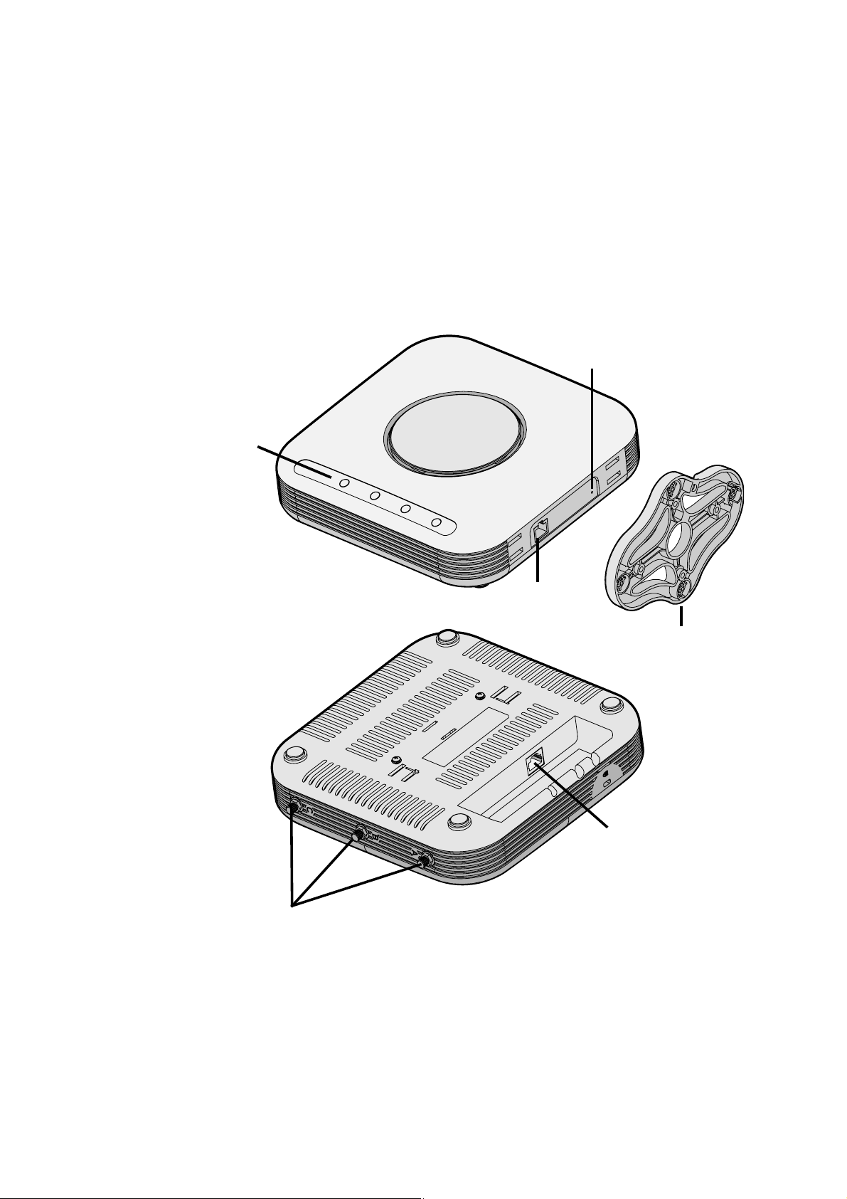
The Figure below shows the the AP, including the LEDs and
connecting ports.
Reset Hole
LEDs
RJ-45 Console Port
Antenna Connectors
Wall Mounting
Bracket /
Table Top Stand
Ethernet Port
Page 20

16 Deciding where to place your AP
Deciding where to place your AP
Place the AP in a dry, clean location near the hub, switch,
computer or printer that will be connected to the AP. The location
must have a power source and be within the following distance of
a Wi-Fi compliant wireless LAN access point or wireless access
point.
The key to maximizing the wireless range is to follow these basic
guidelines:
■ Keep your product away (at least 3-6 feet or 1-2 meters) from
electrical devices or appliances that generate RF noise. The
location should be away from transformers, heavy-duty
motors, fluorescent lights, microwave ovens, refrigerators.
■ Keep the number of walls and ceilings between the AP and
other network devices to a minimum - each wall or ceiling can
reduce your AP’s range from 3-90 feet (1-30 meters.) Position
your devices so that the number of walls or ceilings is
minimized.
■ Be aware of the direct line between network devices. A wall
that is 1.5 feet thick (0.5 meters), at a 45-degree angle
appears to be almost 3 feet (1 meter) thick. At a 2-degree
angle it looks over 42 feet (14 meters) thick! Position devices
so that the signal will travel straight through a wall or ceiling
(instead of at an angle) for better reception.
■ Building materials can impede the wireless signal - a solid
metal door or aluminum studs may have a negative effect on
Page 21

Wall Mounting the Wireless Access Point 17
range. Try to position wireless devices and computers with
wireless adapters so that the signal passes through drywall
or open doorways and not other materials.
Wall Mounting the Wireless Access Point
Use the mounting bracket that comes with your Access Point to
install it on a wall or electrical box.
To wall-mount the Access Point:
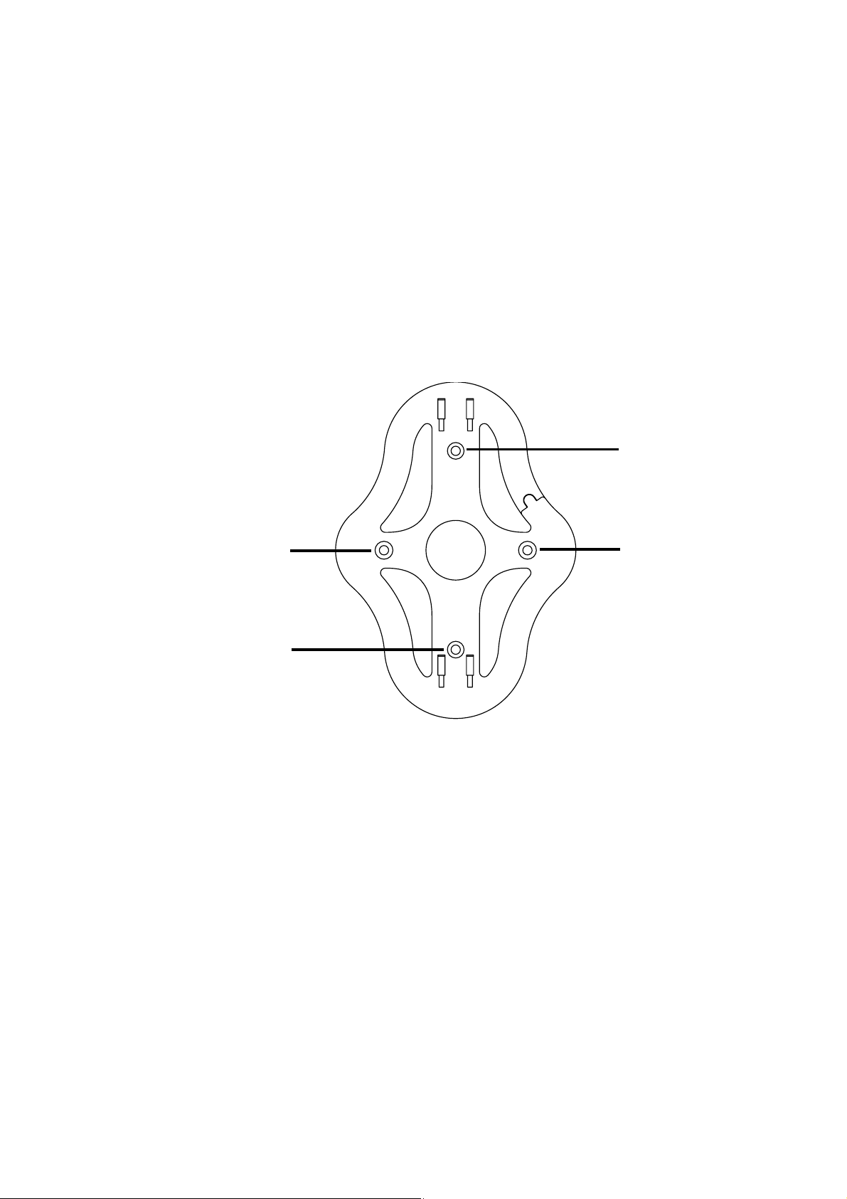
1 Screw the mounting bracket to a wall or electrical box
(NEMA enclosure):
• If mounting to drywall, use the four screws and four wall
anchors.
• If mounting to an EU electrical box (60.3mm), use two
threaded screws and insert into the holes maked “A” in
the diagram shown below.
Page 22
18 Wall Mounting the Wireless Access Point
• If mounting to a US electrical box (83.3mm), use two
threaded screws and insert into the holes maked “B” in
the diagram shown below..
B
A
A
B
2 Connect the Ethernet cable (for power and network
connection) to the port on the back of the Access Point.
Page 23
Wall Mounting the Wireless Access Point 19
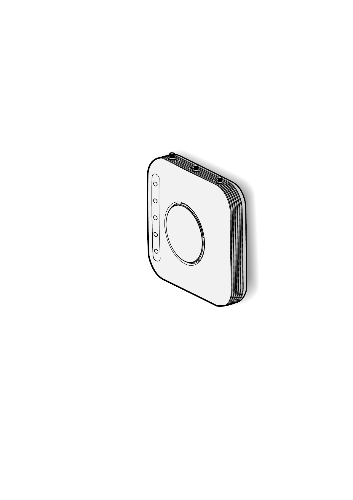
3 Mount Access Point onto the mounting bracket.
Page 24
20 Wall Mounting the Wireless Access Point
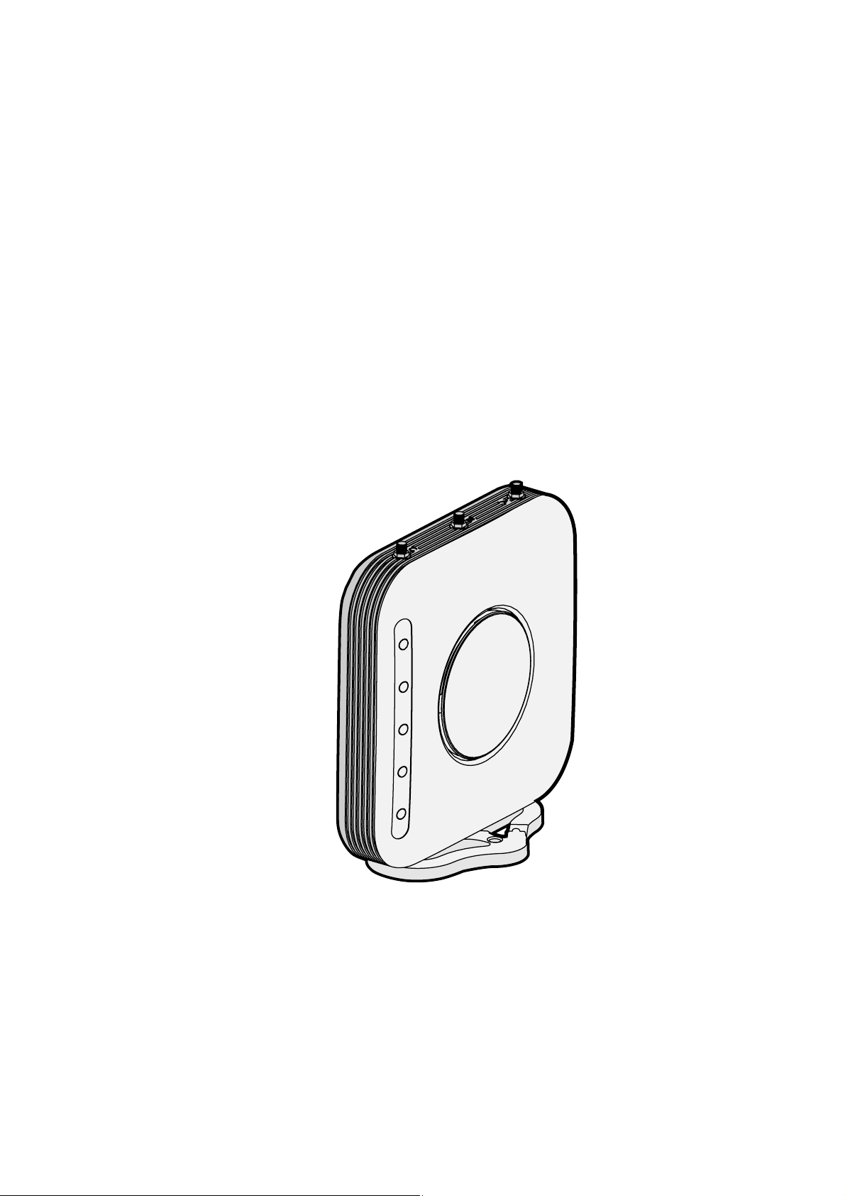
Tabletop Mounting
To install the Access Point on a flat surface such as a table or
desktop:
1 Attach the mounting bracket/table stand to the side of the
Access Point.
2 Place the Access Point and table stand on the table.
3 Connect the Ethernet cable (for power and network
connection) to the port on the back of the Access Point.
Page 25
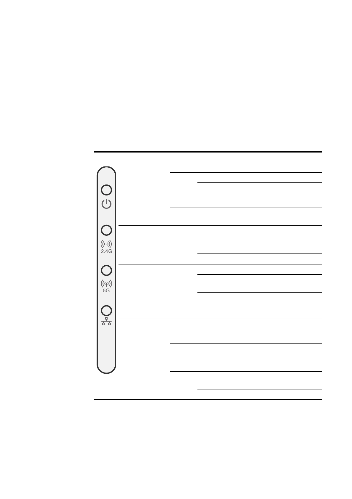
Checking the LED Indicators
When the AP is connected to power, LEDs indicate activity as
follows:
Indicator Color State Description
Wall Mounting the Wireless Access Point 21
LED 1
(Power/
System)
LED 2 (2.4G) Green Off Administratively disabled
LED 3 (5G)
(3Com
AirConnect
9550 11n
2.4+5GHz PoE
Access Point
only)
LED 4
(Ethernet)
Amber On CPU or system fail
Green On Powered on and ready for
Green Off Administratively disabled
Off No power
Blinking System initiation or reset
(software self testing and
loading)
operation
On Associated with network,
but no activity
Blinking Activity
On Associated with network,
but no activity
Blinking Activity
Off No 10/100/1000 base T link
detected, or
administratively disabled
Amber On 10/100 base T link
detected, but no activity
Blinking 10/100 base T link activity
Green
On 1000 base T link detected,
but no activity
Blinking 1000 base T link activity
Page 26

22 Wall Mounting the Wireless Access Point
Power up
Self test (POST)
At power up, the product will carry out a self-test (POST). POST
will run a test on the wireless circuit to check it is functioning
correctly.
When running the POST test, LED 1 (Power/System) will blink
amber.
When firmware is corrupted, LED 1 (Power/System) will be solid
amber.
Page 27

3
Networks with a DHCP Server 23
CONFIGURING THE WIRELESS
ACCESS POINT
If the default AP configuration does not meet your network
requirements, or if you want to customize the settings for your
own network, you can use these tools to change the
configuration:
1 Launch the 3Com Wireless Infrastructure Device Manager
(Widman) utility
2 Directly connect to the device through its Ethernet port or
console port
Networks with a DHCP Server
If your network has a DHCP server, an IP address is automatically
assigned to the AP. It takes between one and two minutes for
the Access Point to determine if there is a DHCP server on the
network. Use the 3Com Wireless Infrastructure Device Manager
(Widman) included on the 3Com Installation CD to locate the
Access Point on the network and view its IP address.
Page 28

24 Networks without a DHCP Server
After you determine the AP’s IP address, you can enter that IP
address into a web browser on a computer on the same subnet to
view the Access Point’s system status or change its configuration.
Networks without a DHCP Server
If your network does not have a DHCP server, the Access Point
uses a factory assigned IP address (169.254.2.2). You can use that
IP address to configure the Access Point, or you can assign a new
IP address to the Access Point.
To verify that the Access Point is using the default IP address
assigned at the factory:
1 Connect a computer directly to the Access Point using the
supplied standard Category 5 UTP Ethernet cable.
2 Enter the Access Point’s default IP address (169.254.2.2) into
the computer’s web browser. If the Configuration Management
System starts, the Access Point is using the factory assigned IP
address. You can configure the Access Point with the following
login information:
■ Login name: admin
■ Password: password
If the Configuration Management System does not start, the
Access Point is on a different subnet than the computer. Install
and start the 3Com Wireless Infrastructure Device Manager to
discover the Access Point’s IP address.
Page 29

Using the 3Com Installation CD 25
Using the 3Com Installation CD
The 3Com Installation CD contains the following tools and
utilities:
3Com Wireless Infrastructure Device Manager—an
administration tool that helps you select 3Com wireless LAN
devices and launch their configurations in your Web browser.
Launch the 3Com Wireless Infrastructure Device Manager
(Widman) utility
1 Turn on the computer.
2 Insert the 3Com Installation CD into the CD-ROM drive.
The CD will Autorun. If it does not Autorun, you can start the
setup menu from the Windows Start menu. For example: Start >
Run > d\:setup.exe.
3 In the menu click Tools and Utilities.
4 In the next screen, click the software you want to install.
5 Follow the on screen instructions to complete the installation.
Reboot the computer if prompted to do so.
Launching the 3Com Wireless Infrastructure
Device Manager
To be able to configure the Access Point you need to run the
Wireless Infrastructure Device Manager. Go to Start >
Page 30
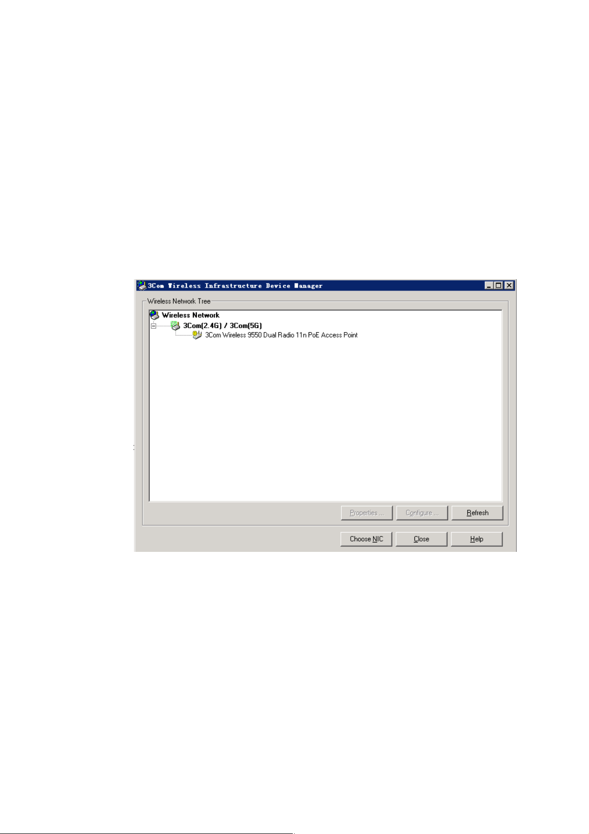
26 Using the 3Com Installation CD
Programs > 3Com Wireless > Wireless Infrastructure Device
Manager
If the device is working correctly the following screen should be
seen.
Page 31
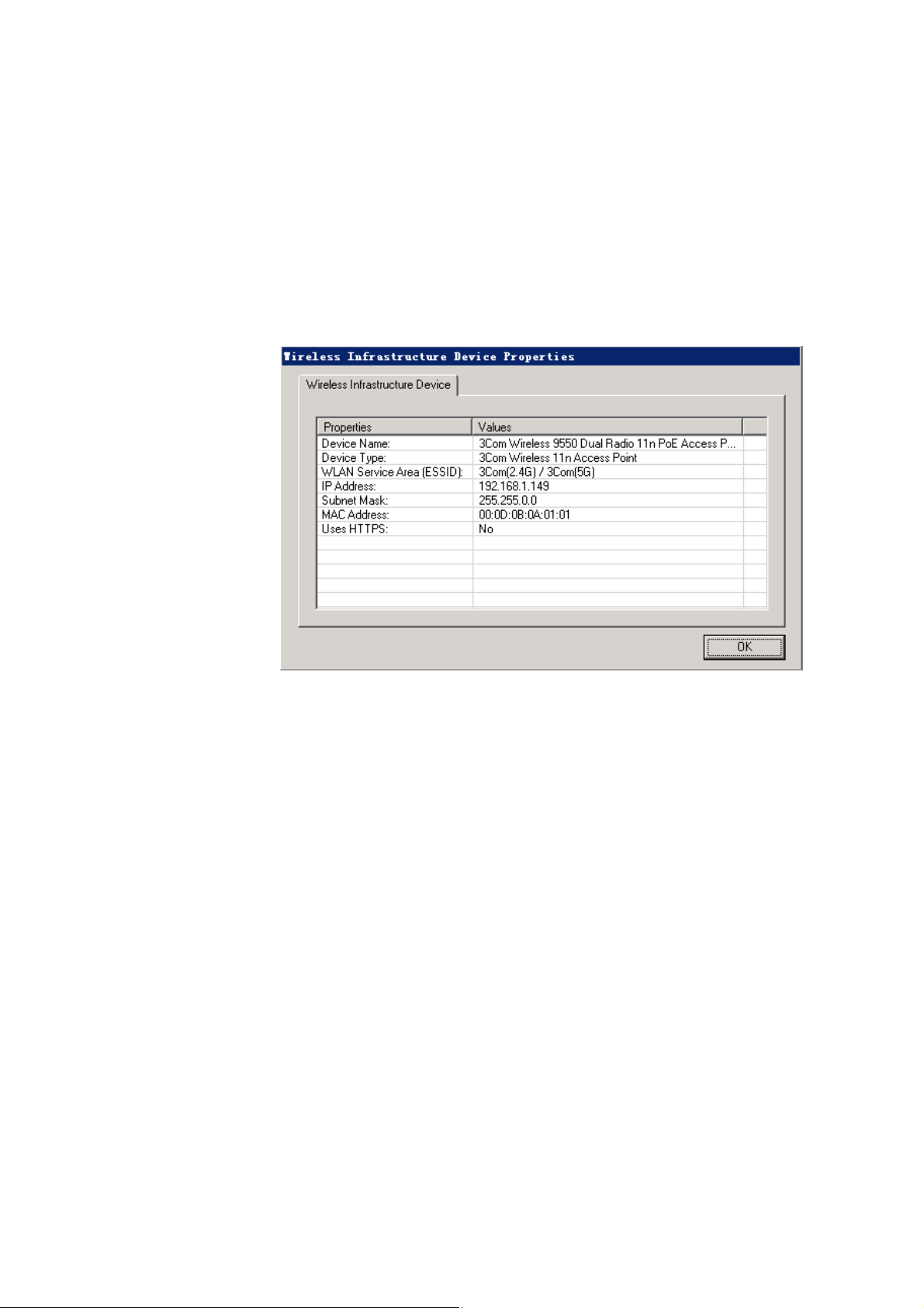
Using the 3Com Installation CD 27
Click on the Properties button to see the following screen
Directly connect to the device through its Ethernet port or
console port.
Follow the instructions below to log into the AP Configuration
screen:
1 Load a web browser and enter http://169.254.2.2
Page 32
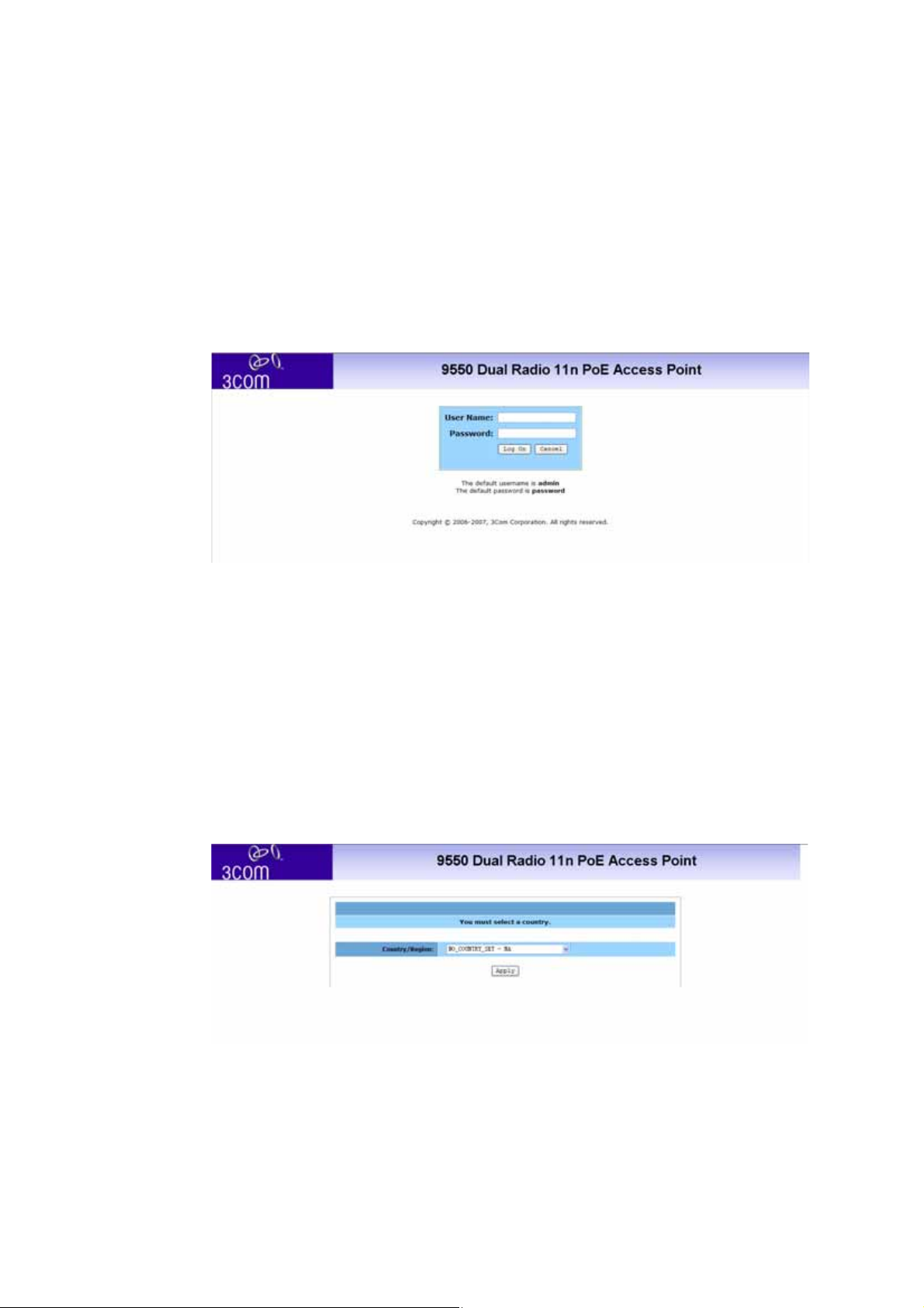
28 Using the 3Com Installation CD
2 The Logon screen appears
To log on to the Web interface:
1 Username, type admin (case sensitive)
2 Password, type password
3 Click Log On.
First Time Only
After you have logged in for the first time you will be asked to
select your country from the drop down menu.
Page 33
System Status
The Web interface has been designed to enable you to easily
perform advanced configuration tasks and view information
about the AP.
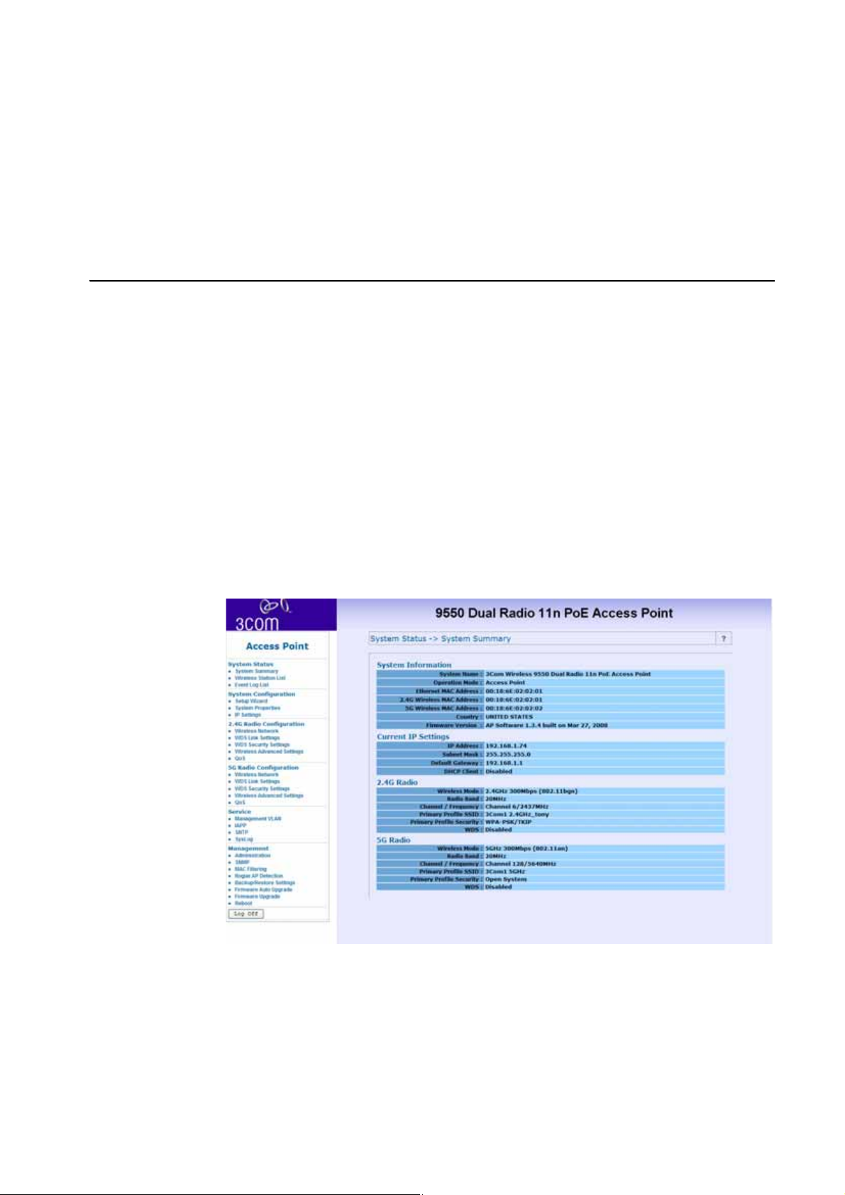
System Summary
After you click Logon from the Log On Screen, you’ll see the
system status page on the screen. The System summary page is
the default page that will pop up once you successfully log in.
The system summary page shows all the configuration
information about your AP.
System Status 29
Page 34
30 System Status
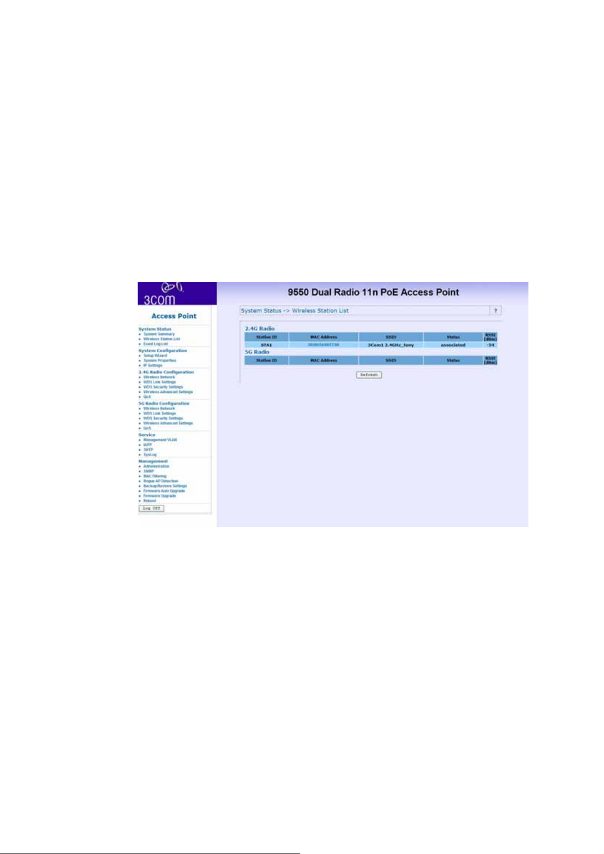
Wireless Station List
Through this page, you can easily identify the adjacent wireless
stations. It will automatically observe the adjacent wireless
station’s ID (if specified), MAC address, SSID and current status.
Page 35
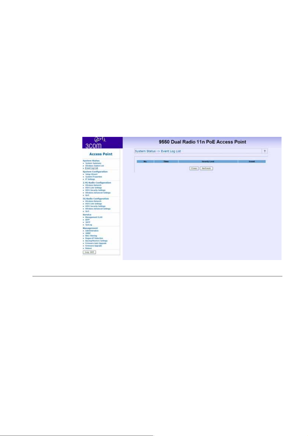
Event Log List
The event log list stores a record of all the events within this
designated WLAN.
System Configuration 31
System Configuration
In this section, you will learn how to configure the basic
functions of your wireless AP.
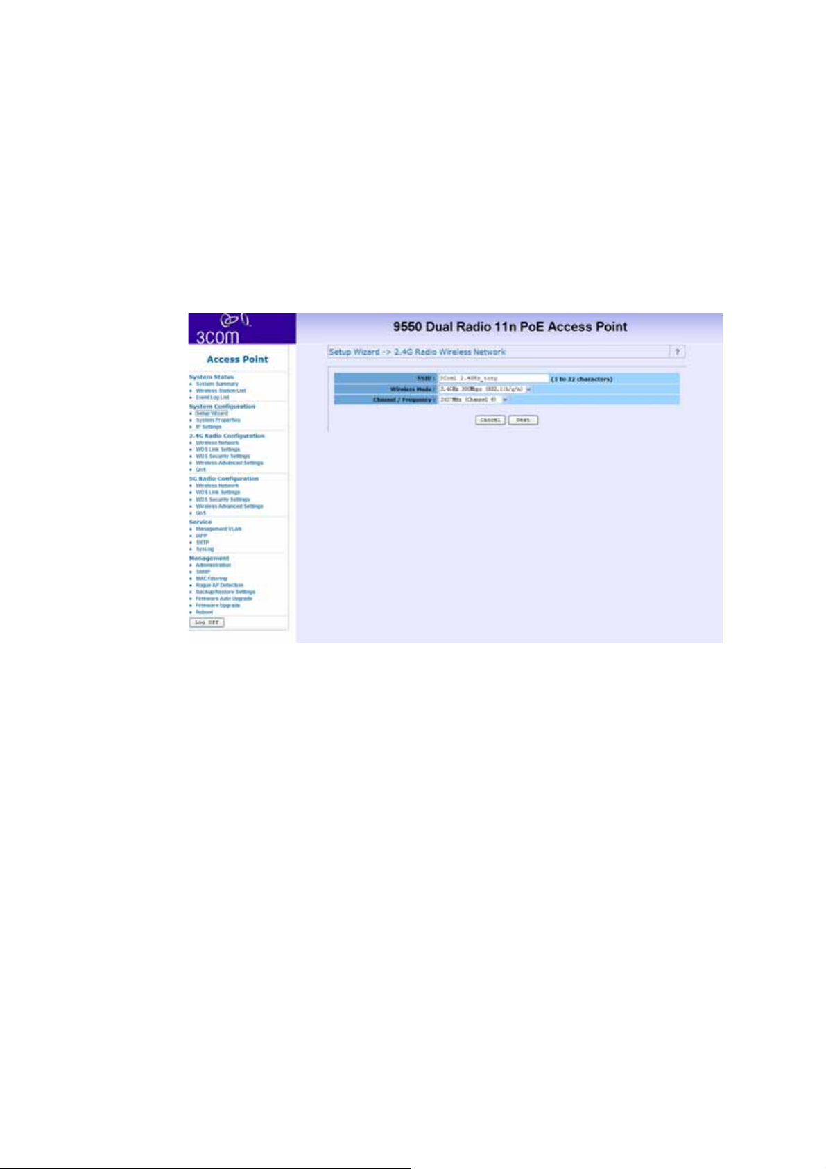
Setup Wizard
The setup Wizard will walk you through the setting up of the
Office Connect Access Point
Page 36
32 System Configuration
Screen 1 allows you to set up the following information:
■ SSID (Service Set Identifier) – This is the name of wireless
network. Input 1-32 characters
■ Wireless Mode – Choose the required network mode from
the drop down menu.
■ Channel/Frequency – Choose a frequency from the drop
down menu or select SmartSelect (recommended) to let the
device select a channel.
Click Next to continue the configuration or click Clear to start
again.
Page 37
System Configuration 33
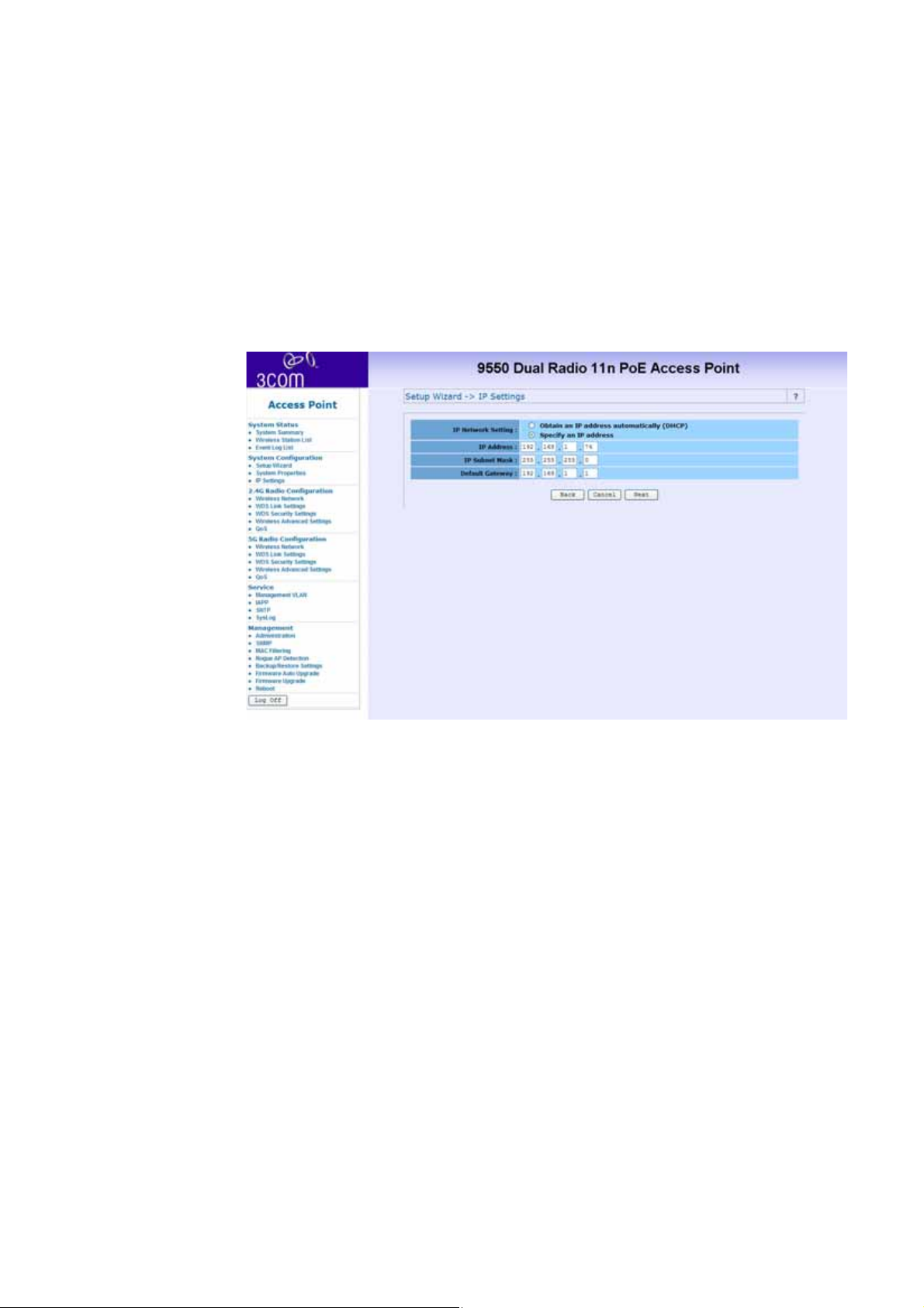
Screen 2 allows you to set up the following information:
■ IP Network Setting – Check the radio button for either
obtaining an IP address via DHCP or specifying an IP Address
manually.
■ IP Address – Enter the IP address that you want to assign.
■ IP Subnet Mask – Enter your networks subnet address.
■ Default Gateway – If used, enter the gateway address that
the device should go through.
Page 38
34 System Configuration
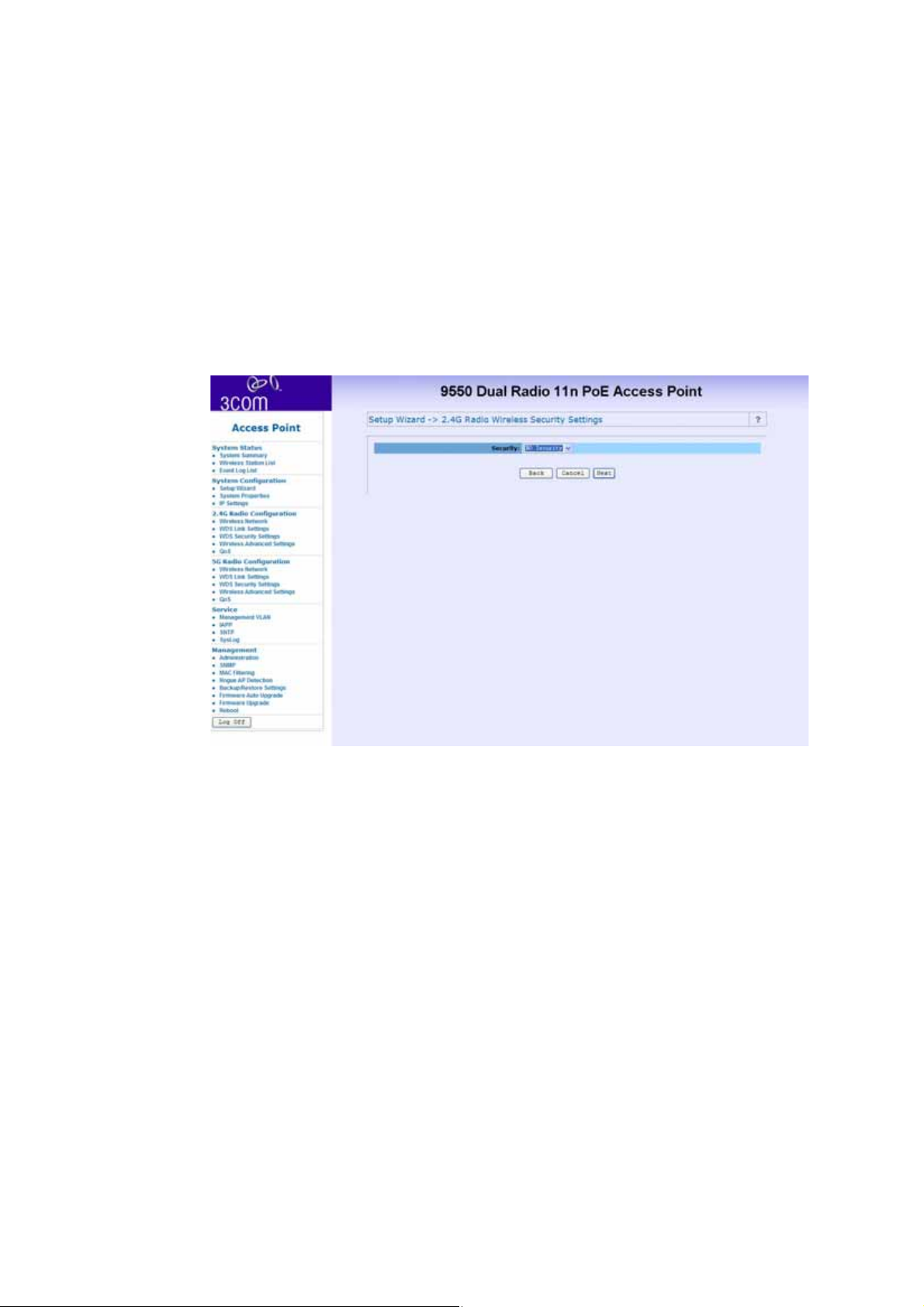
Screen 3 allows you choose the security settings. Choose the
following settings from the drop down menu:
■ No security
■ WEP
■ WPA - Only
■ WPA2 - Only
■ WPA2 - Mixed
Click Close to close without saving, click Finish to save the
settings, or click Back to return to screen 2.
Page 39

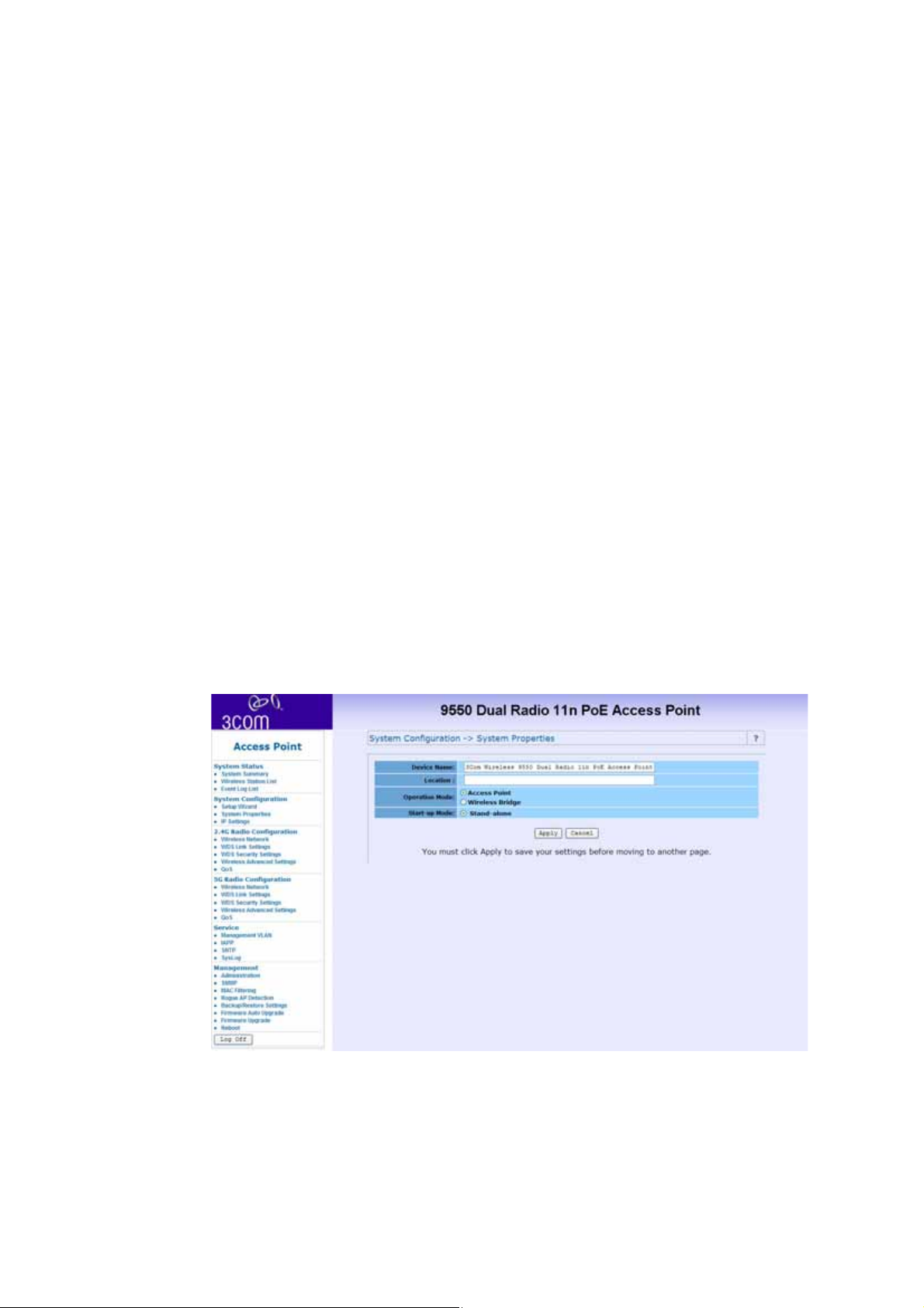
System Properties
The System properties page allows you to define Device name,
location, operation modes and Load Type.
There are 5 operation modes to choose from:
Access Point mode
A Wireless LAN data transceiver that uses radio waves to connect
a wired network with wireless station.
Wireless Workgroup Bridge mode (Client Bridge
mode)
It acts as a wireless client in the network. Through this mode,
you can connect to an access point through this device.
System Configuration 35
Ad-hoc mode (peer to peer)
An Ad-hoc mode allows 2 wireless clients to communicate to
each other. An Ad-hoc network is a wireless network composed
of stations without Access Points.
Repeater mode
A repeater is placed between two access points to extend the
range of your infrastructure or to overcome an obstacle that
blocks radio communication.
Page 40
36 System Configuration
Wireless Bridge mode
A wireless bridge connects two separate networks operating on
the 802.11 standard.
Load Types are either:
FAT
Default is set to be FAT mode AP. FAP AP has complete set of AP
features which can work alone as an individual AP.
FIT
FIT mode AP needs to be connected to a 3Com Wireless Switch to
provide complete feature sets.
Page 41
IP Settings
System Configuration 37
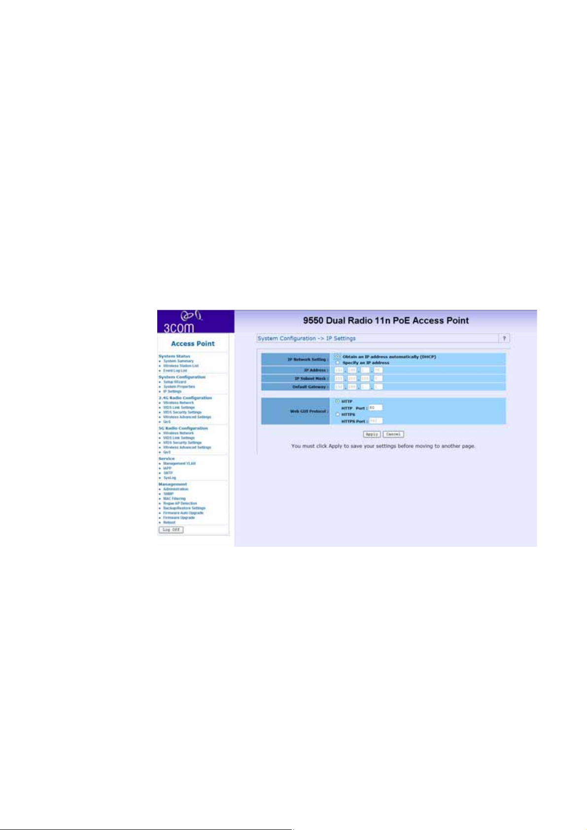
This setting must match the network’s method of IP address
assignment. Choose DHCP or Static IP. With Dynamic Host
Configuration Protocol (DHCP), IP addresses are assigned for
predetermined periods of time. Choose Static IP if your network
does not have an automatic system for IP address assignment.
Page 42
38 System Configuration
Wireless Network
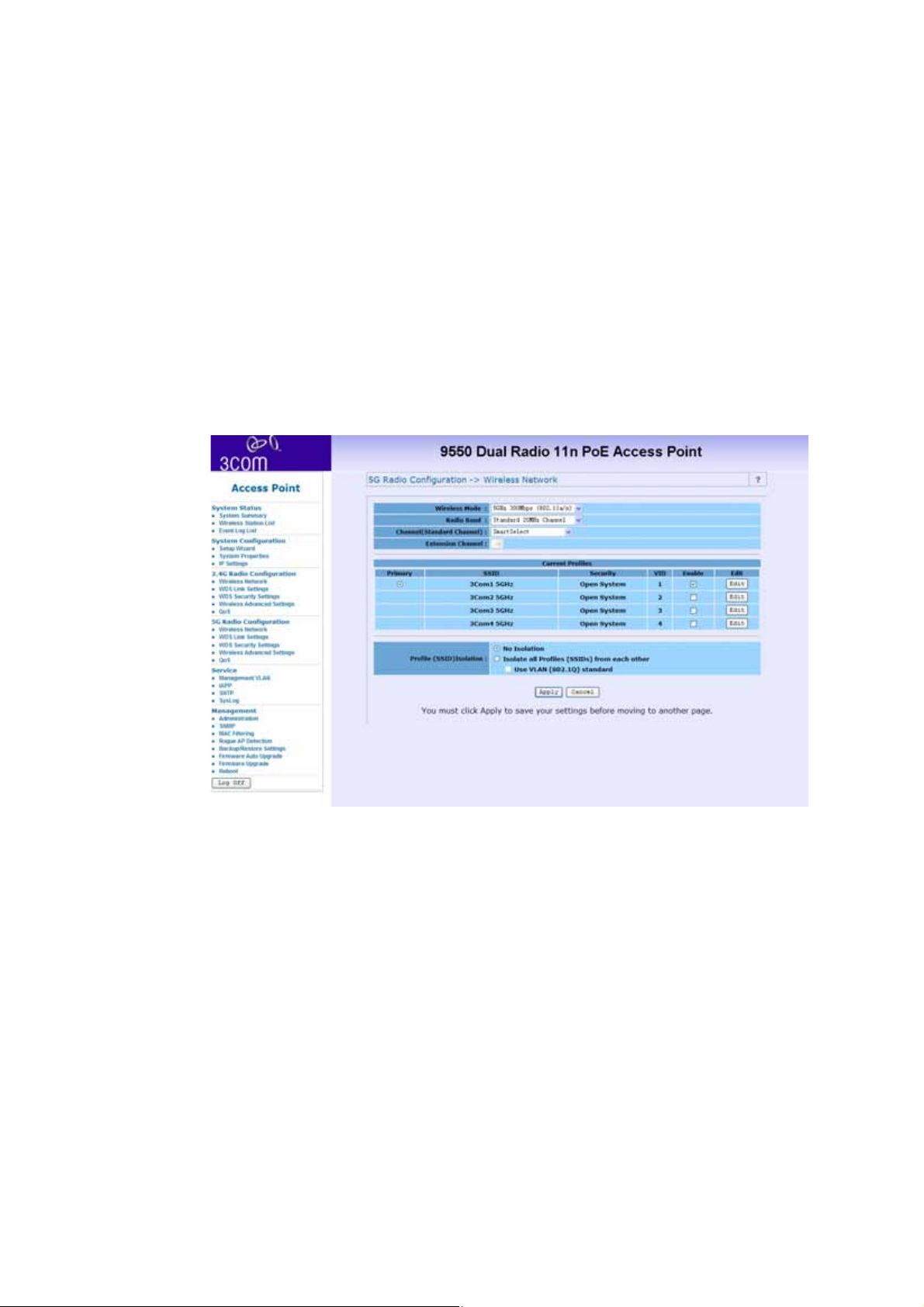
The Wireless Access Point supports Multiple SSIDs which allows it
to act as multiple APs appearing in a Wireless LAN network. You
can configure up to 4 SSIDs on the device.
Wireless Mode
You can select your desired wireless operating mode from the
drop-down manual.
The AP supports Super Dynamic and Static modes and boosts
throughput up to 108 Mbps.
Page 43

System Configuration 39
The Super Dynamic mode allows automatic switching between
normal and turbo modes without modification by the user. The
feature increases throughput when bandwidth demands are
high. When bandwidth demands are low and at regular
intervals, normal mode allows legacy connectivity and new
associations. The Super Dynamic mode connection between the
Ethernet Adapter and the access point may turn to normal mode
connection if another station associates with the access point in
normal mode. The Super Static mode operates by using two
radio channels and does not switch to normal mode. Super Static
mode must be configured by the user on both the access point
and the station.
Note that in order to enable Super mode, the opposite client
service needs to provide the same specification.
Channel / Frequency
Select the channel for your wireless LAN in Channel/Frequency
block. The default setting is SmartSelect it selects the channel
which provides the best transmission quality. The frequencies
available vary depending which wireless mode you select.
Page 44
40 System Configuration
Current Profiles
A maximum of 4 profiles can be configured. Check the Enable
button to activate a profile. Click the Edit button to change its
configuration.
SSID
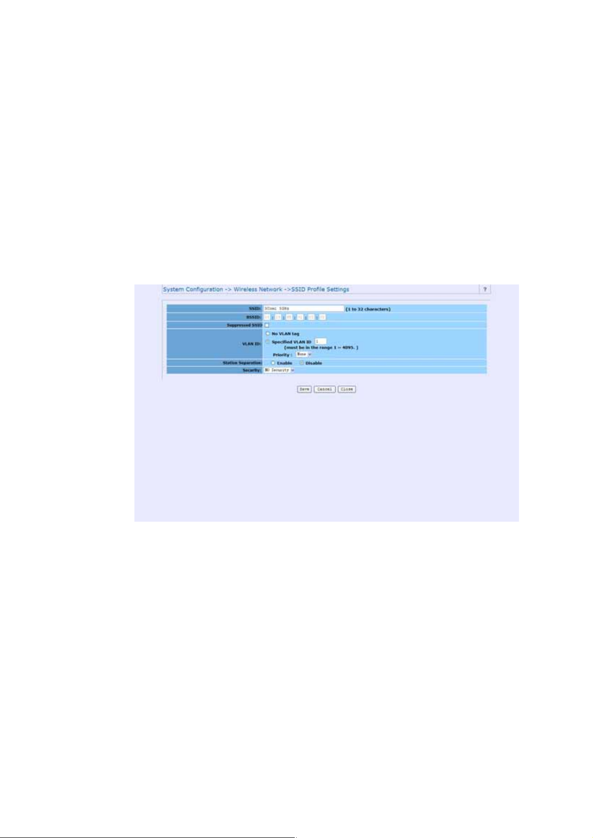
Service Set Identifier. This is the assigned name for a wireless Wi-Fi
network. Stations must use this unique identifier to communicate
with an Access Point. The SSID can be any alphanumeric entry up
to a maximum of 32 characters.
Page 45

System Configuration 41
BSSID
Basic Service Set Identifier. This is the assigned MAC address of
the station in the access point. This unique identifier is in Hex
format and can only be edited when Multi BSSID is enabled in
the previous screen.
Suppressed SSID
If you want to disable the broadcast of your SSID, you should
check the Suppressed SSID box. It is also known as SSID
Broadcast disable or Hide SSID.
VLAN ID
If your network uses VLANs, you can assign an SSID to a VLAN.
Client devices using the SSID are grouped in that VLAN.
Station Separation
Choose either enable or disable to control the selected VAP
(Virtual Access Point).
Security
There are 4 levels of security available and all have differing
properties:
Page 46
42 System Configuration
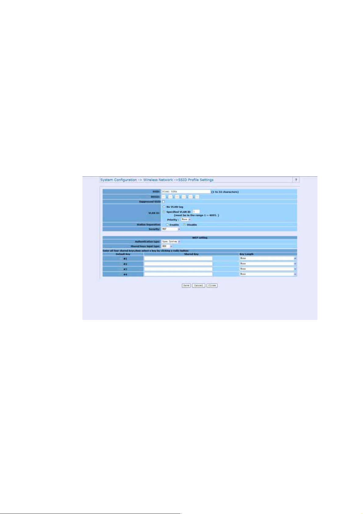
WEP
Wired Equivalent Privacy data encryption provides data security.
WEP Share Key authentication and WEP data encryption will block
all but the most determined hacker.
From the drop down list choose open-system or shared key
authentication.
Select the desired input method (HEX or ASCII)
From the drop down list choose from 40/64, 104/128, 128/152
key lengths.
Page 47
System Configuration 43
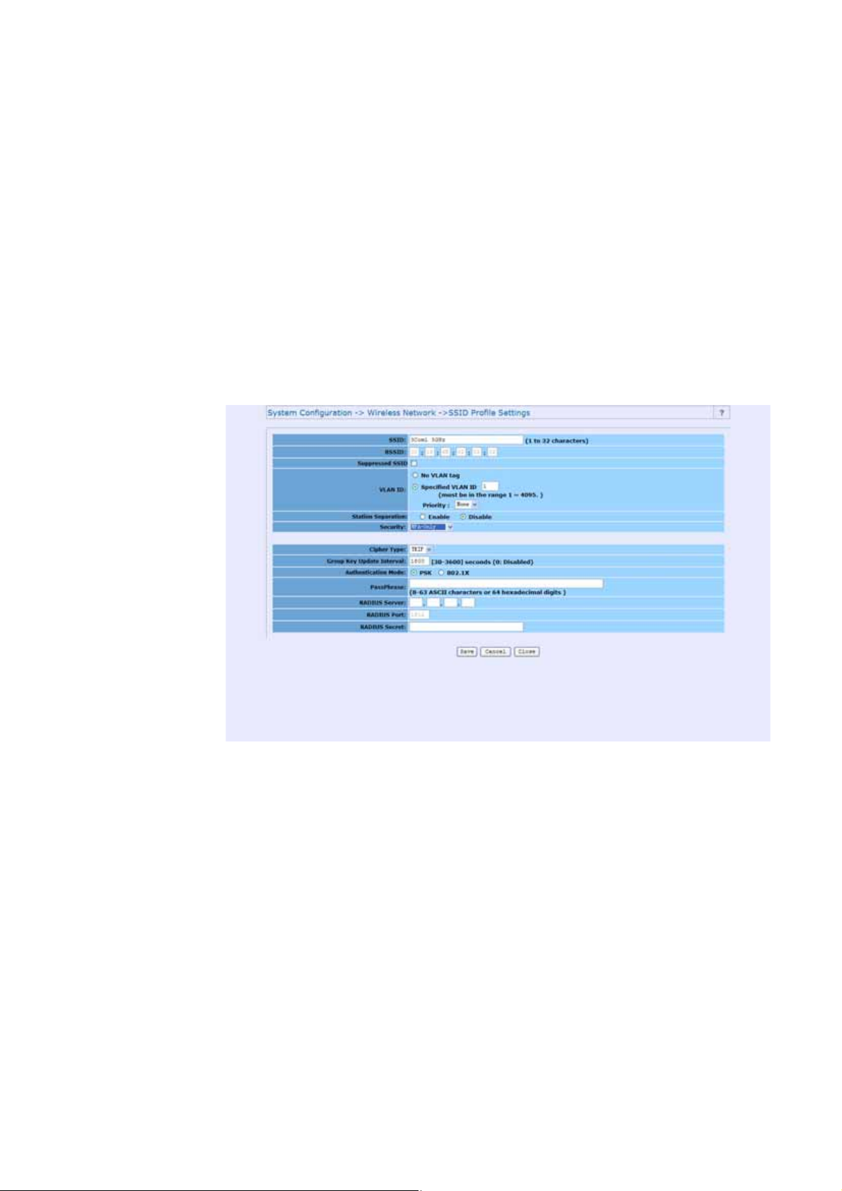
WPA Only
Wi-Fi Protected Access was constructed to provide improved
data encryption, (which was weak in WEP), and to provide user
authentication.
Only allows WPA clients to connect to the VAP.
You can choose TKIP or AES for encryption method
The Group key update interval is configurable, default value is
1800 seconds
You can choose personal mode (PSK) or enterprise mode
(802.1X) authentication (default: PSK).
Page 48

44 System Configuration
If you choose PSK, you will need to enter a pass phrase of 8-63
ASCII characters or 64 hexadecimal digits.
If you choose 802.1X, you will need access to a RADIUS server,
port and secret
WPA2-Only
Only allows WPA 2 clients to connect to the VAP.
You can choose TKIP or AES for the encryption method
The Group key update interval is configurable, with a default
value of 1800 seconds
You can choose personal mode (PSK) or enterprise mode (802.1X)
authentication (default: PSK).
If you choose PSK, you will need to enter a pass phrase of 8-63
ASCII characters or 64 hexadecimal digits.
If you choose 802.1X, you will need access to a RADIUS server,
port and secret.
WPA2-Mixed
Only allows both WPA and WPA2 clients to connect to the VAP.
You can choose TKIP or AES for encryption method.
The Group key update interval is configurable, with a default
value of 1800 seconds.
Page 49

System Configuration 45
You can choose personal mode (PSK) or enterprise mode
(802.1X) authentication. The default setting is PSK.
If you choose PSK, you will need to enter a pass phrase of 8-63
ASCII characters or 64 hexadecimal digits.
If you choose 802.1X, you will need access to a RADIUS server,
port and secret.
Profile (SSID) Isolation
Stations connected to different profiles cannot access each
other. Choose from No Isolation (Full access), or to Isolate all
Profiles (SSIDs) from each other, check use VLAN (802.1Q)
standard.
Multi-BSSID
Check enable Multiple BSSIDS to allow each profile to send an
individual beacon and station separation configuration. This can
be done either manually or automatically.
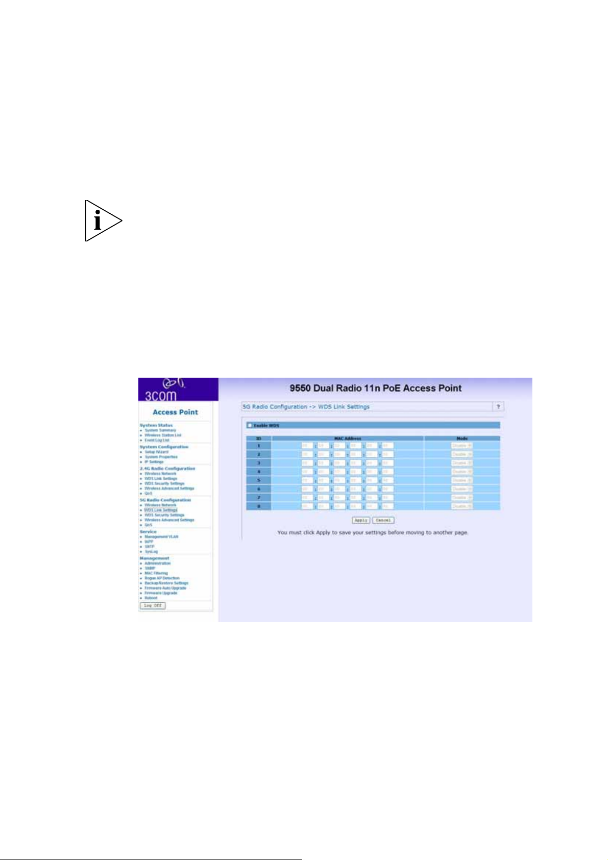
WDS Link Settings
WDS (Wireless Distribution System) allows access points to
communicate with one another wirelessly in a standardized way.
It can also simplify the network infrastructure by reducing the
amount of cabling required. Basically the access points will act as
a client and an access point at the same time.
Page 50
46 System Configuration
WDS is incompatible with WPA. Both features cannot be used at
the same time. A WDS link is bi-directional, so the AP must know
the MAC address of the other AP, and the other AP must have a
WDS link back to the AP.
Dynamically assigned and rotated encryption keys are not
supported in a WDS connection. This means that WPA and other
dynamic key assignment technologies may not be used. Only
Static WEP keys may be used in a WDS connection, including any
STAs that are associated with a WDS repeating AP.
Enter the MAC address of the other APs you want to link to and
click enable.
Page 51
Supports up to 8 point to multipoint WDS links, check Enable
WDS and then enable on the MAC addresses.
Example of a WDS topology:
AP1 <-- WDS --> Master AP (our AP) <-- WDS --> AP3<-- WDS
--> AP4
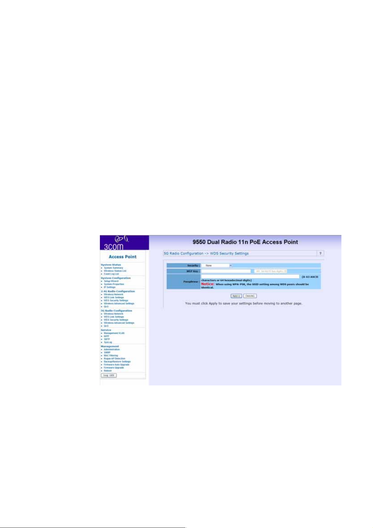
WDS Security Settings
This item is only available in Access Point Mode and Wireless
Bridge Mode.
System Configuration 47
Choose the required security level from: None, WEP, WPA-PSK
(TKIP), WPA-PSK (AES), WPA2-PSK (TKIP),or WPA2-PSK
(AES).
Page 52
48 System Configuration
If using WEP security, enter the WEP key. If using WPA, enter the
pass phrase.
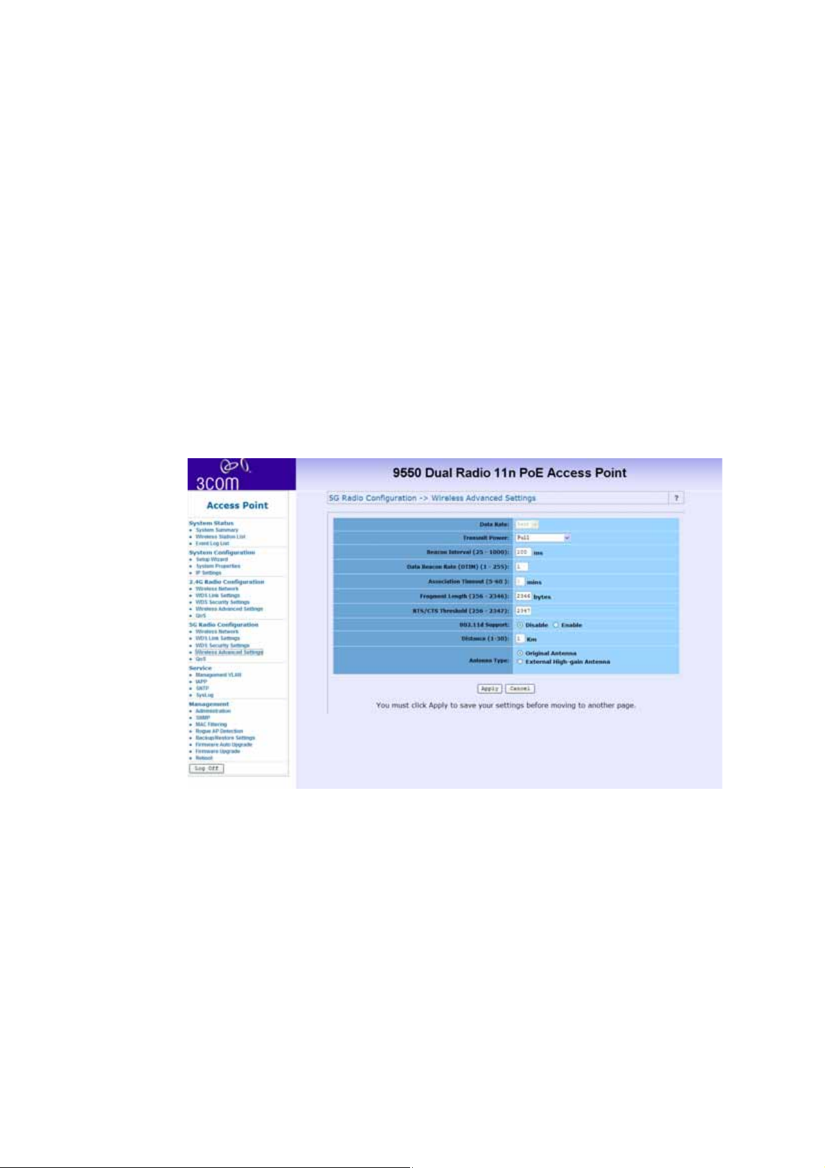
Wireless Advanced Settings
To configure advanced wireless settings, click Wireless
Advanced Settings. The tool bar and Wireless Advanced
Settings menu will appear.
Data Rate
Choose between the following data rates 12, 18, 24, 36, 48, 72,
96, 108, and best. Default is Best.
Page 53

System Configuration 49
Transmit Power
Choose between the following power levels Full, Half (-3dB),
Quarter (-6dB), Eighth (-9dB) or Minimum. Default is Full.
Beacon Interval
The interval time between 20ms and 1000ms for each beacon
transmission. The default is 100ms.
Data Beacon Rate (DTIM)
The Delivery Traffic Indication Message. Specify the data beacon
rate between 1 and 255. Default is 1.
Fragment Length
The maximum packet size is used for fragmentation. Packets
larger than the size programmed in this field will be fragmented.
The Fragment Threshold value must be larger than the RTS
Threshold value. The default is 2346.
RTS Threshold
Request To Send threshold. The packet size that is used to
determine if it should use the CSMA/CA mechanism or the
CSMA/CD mechanism.
Page 54

50 System Configuration
802.11d support
802.1d allows the device to communicate in areas where the
802.11 standard is not allowed. It adds features and restrictions to
ensure compliance.
Antenna Type
If you have added external antennas (to replace the original
included 3 internal antennas), check the External High-Gain
Radio Antenna radio button.
Page 55
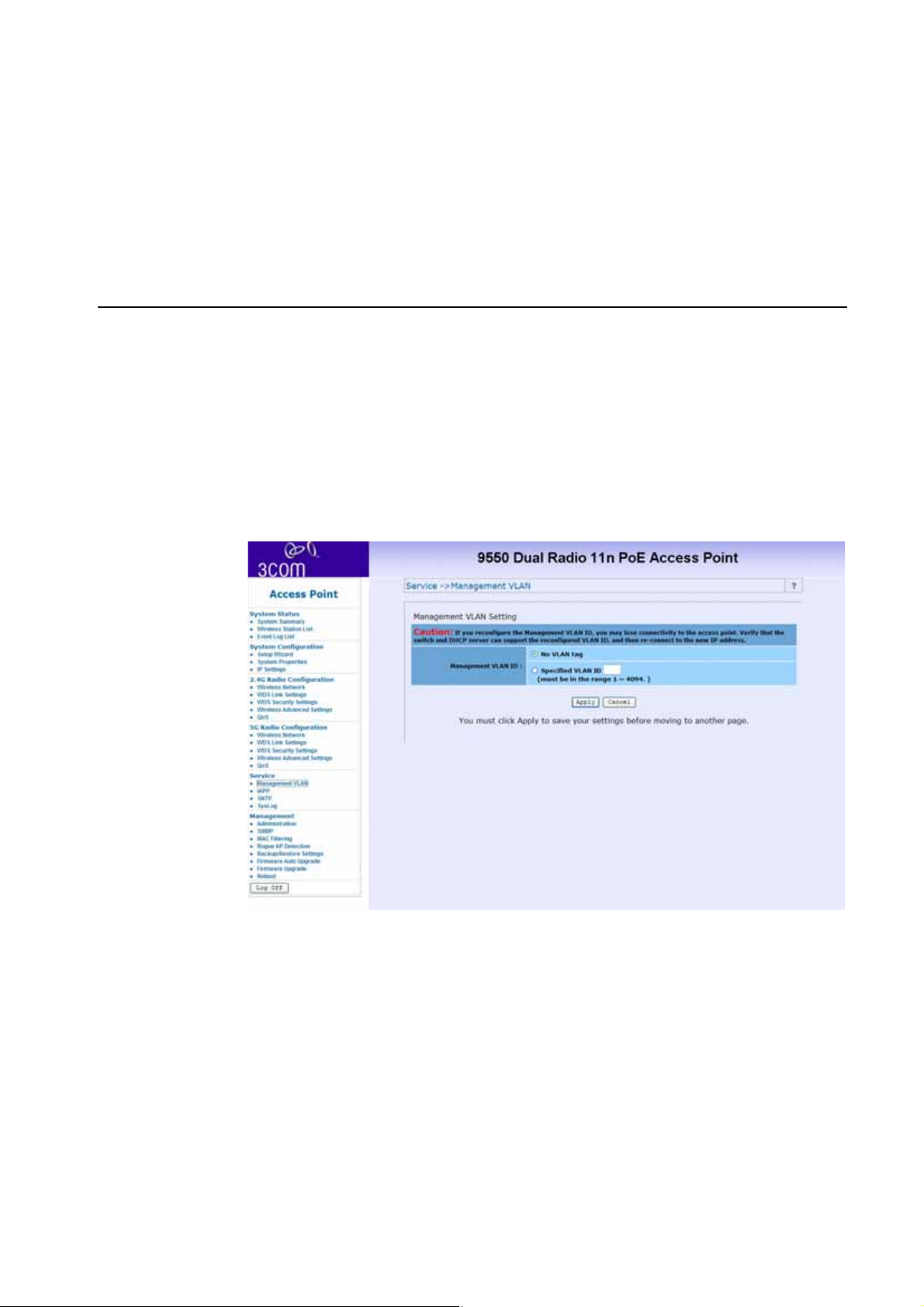
Service
Management VLAN
If you reconfigure the Management VLAN ID, you may lose
connectivity to the access point. Verify that the switch and DHCP
server can support the reconfigured VLAN ID, and then
re-connect to the new IP address.
Service 51
Page 56
52 Service
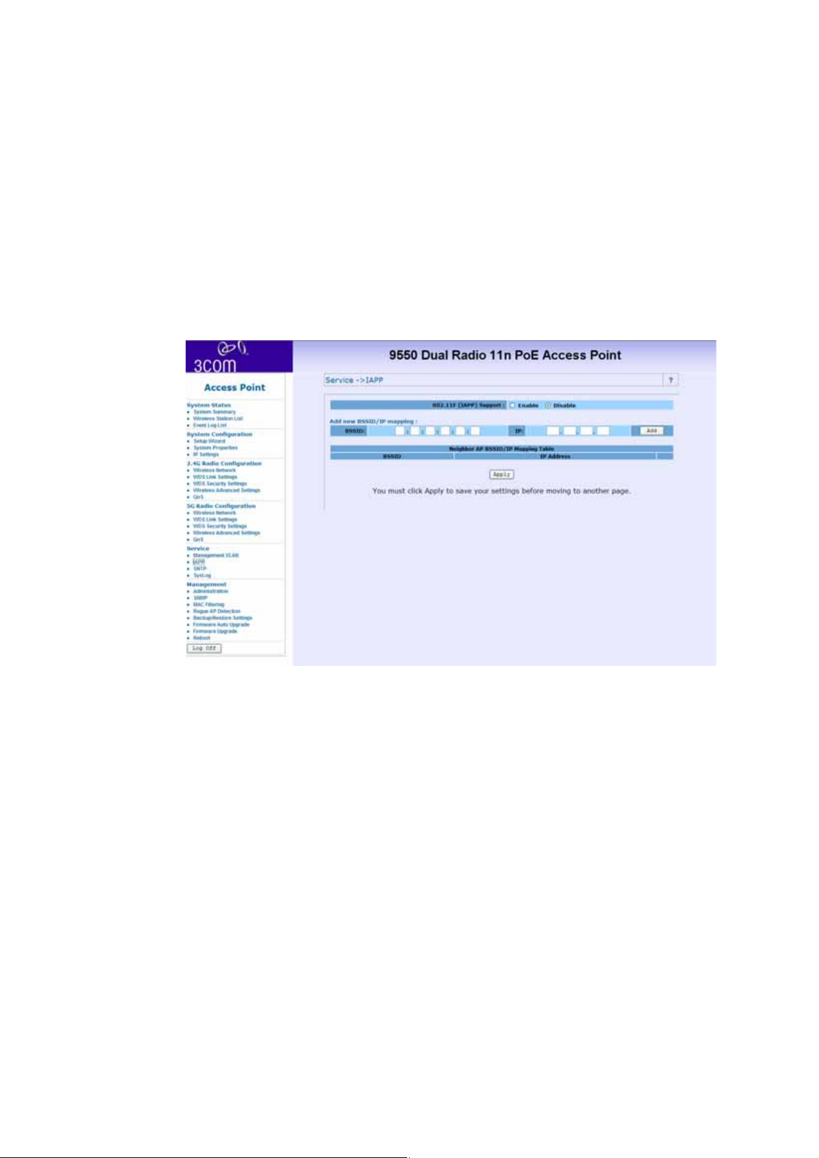
IAPP
Inter-Access Point Protocol (IAPP)
802.11F (IAPP) Support - Choose either Enable or
Disable
IAPP allows multiple access points to communicate and pass
location information about their associated stations. If you enable
802.11F support you should manually add BSSID/IP mapping:
■ Enter the BSSID and IP addresses of the AP.
■ Click Add
Page 57
Service 53
Only stations roaming from one of the listed APs to this AP are
allowed to re-associate with this AP. Others will be requested to
go through the full association process.
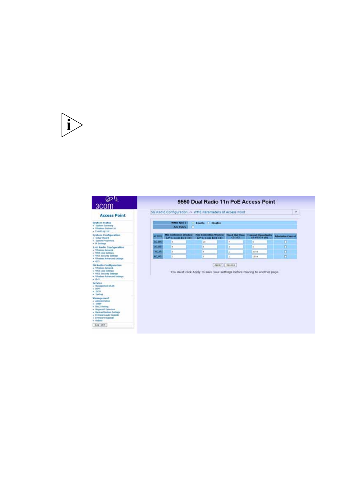
QoS
This section provides the administrator with the Quality of
Service (QoS) data.
The QoS setting is only available in AP Mode and Wireless Client
Mode.
The QoS Setting should be modified with caution because radio
behavior is affected. These parameters can be modified when
the radio for QoS service is Enabled.
Page 58

54 Service
Ack-Policy - when the Ack-Policy is checked. The device will not
send ACK frames. The default value is disabled.
Setting Description
Min Contention
Window
Max Contention
Window
Fixed Slot Time For each access category, enter the fixed slot time.
Transmit
Opportunity Limit
For each access category, enter the minimum
contention window value. Channel access is
prioritized by assigning smaller contention
window values to a higher priority traffic class. If a
channel is busy or a transmission collides, a node
chooses a random number between 0 and the
current contention window minimum.
For each access category, enter the maximum
contention window value. The minimum
contention window value is doubled each time a
collision occurs until the maximum is reached. A
small contention window value decreases the
access delay but increases the probability of a
collision.
Channel access can be strictly prioritized by
assigning smaller contention window values to a
higher priority traffic class. Traffic in the access
category must wait for this fixed number of slots
after each packet is received before resuming its
random back-off.
Enter the number of microseconds that qualified
transmitters can transmit through the normal
back-off procedure with a set of pending packets.
Larger values allow a client to control the channel
for longer periods of time, allowing it to achieve
higher throughput in this access category at the
expense of longer access times for all access
categories.
Page 59

Setting Description
Service 55
Admission
Control
Note: In this release, clients are blocked from
using an access category when they select Enable
for Admission Control. The Admission Control
check boxes control client use of the access
categories. When you enable admission control
for an access category, clients associated to the
access point must complete the WMM admission
control procedure before they can use that access
category. However, access points do not support
the admission control procedure in this release, so
clients cannot use the access category when you
enable Admission Control.
default : disable
The default value table:
Min
Contention
AC TYPE
AC_BK 4 10 7 0
Window
(2x-1; x can
be 0-10)
Max
Contention
Window
(2x-1; x can
be 0-10)
Fixed
Slot
Time
(0-15)
Transmit
Opportunity
(0-65535 μS)
AC_BE 4 6 3 0
AC_VI 3 4 1 3008 (6016
when 11b)
AC_VO
(3)
2 3 1 1554 (3264
when 11b)
Page 60
56 Service
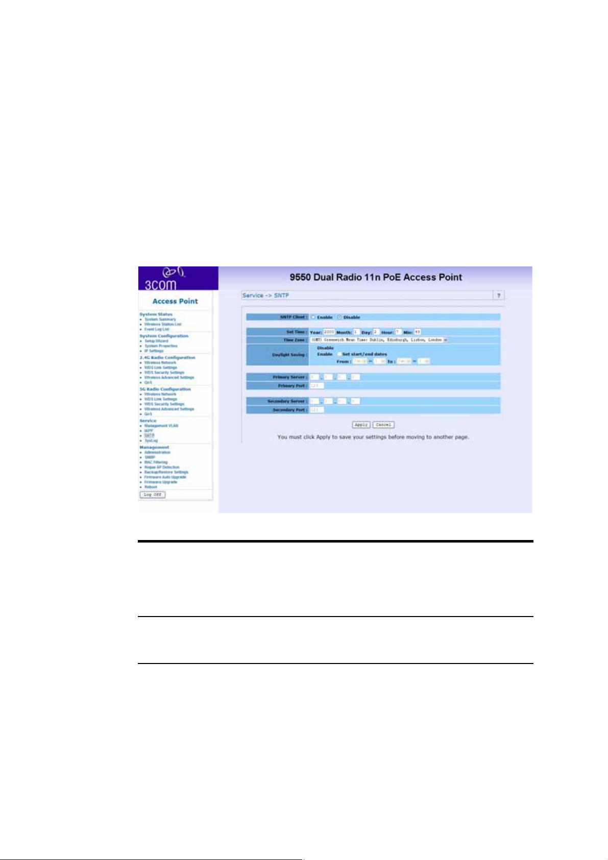
SNTP
Simple Network Time Protocol (SNTP) allows the administrator to
configure the network time settings.
The following settings can be configured.
SNTP client
enable/disable
Set Time Includes Year, Month, Day, Hour and Minute.
Click the radio button to enable.
If it is disabled, the user has to input time
manually.
If it is enabled, the device will try to fetch time
from configured SNTP servers.
These fields are grayed out and un-configurable if
SNTP is enabled.
Page 61

Service 57
Timezone selection This selection will adjust the time obtained from
the SNTP server.
Note: This selection does not affect manual time
input as they are considered to be input at the
same time.
Daylight Saving The start/end date of daylight saving will change
automatically based on the time zone selection.
Note: Start and End dates can be input manually,
to avoid any regional policy changes.
Primary and
Secondary SNTP
server/port setting
If SNTP is enabled, this device will try to fetch
time from the primary server first. The timeout for
primary NTP server is 5 seconds.
If the Primary NTP server fails after 5 seconds the
Secondary NTP server will be tried for 5 seconds.
In the event that the secondary server fails, the
device will wait for 60 seconds before trying the
Primary server again. This continues until a time is
available.
To avoid using an invalid NTP server address, this device will store
the fetched/configured time. After it boots up, it will use the
stored time first and adjust time if time is fetched.
Page 62
58 Syslog function
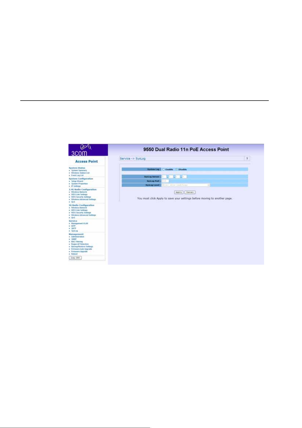
Syslog function
In the event of an error the device can send a message to a
specified server.
System Log
Syslog Server
Click either Enable or Disable to activate or deactivate the system
log function.
Enter the IP address of the server that will receive the error
information. The default IP address is 0.0.0.0
Page 63

Syslog Port
Syslog Level
Syslog function 59
Enter the port number that your server can be accessed by. The
default port number is 514.
Choose from the following levels - in order of severity - of detail
to be recorded. The default setting is Error.
■ Emergency - System is unusable
■ Alert - Action must be taken immediately
■ Critical - Critical condition
■ Error - Error condition
■ Warning - Warning condition
■ Notice - Normal, but significant condition
■ Informational - Informational messages
Page 64
60 Management
Management
This section describes how to use the management and
information features of your Wireless Access Point.
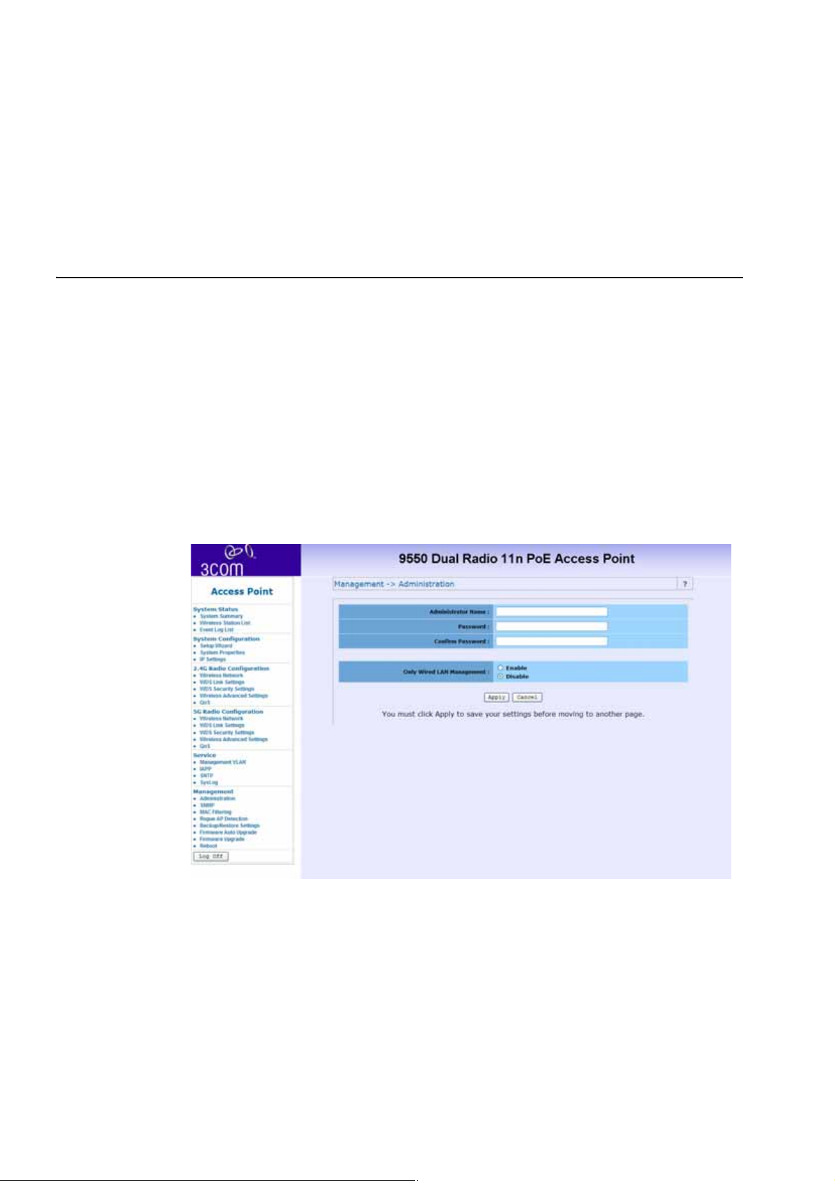
Administration
In this section, you can change the user administrator name and
password. The default Administrator name is admin (case
sensitive), and password is password. Click “Apply” to save
changes.
Page 65
SNMP
Management 61
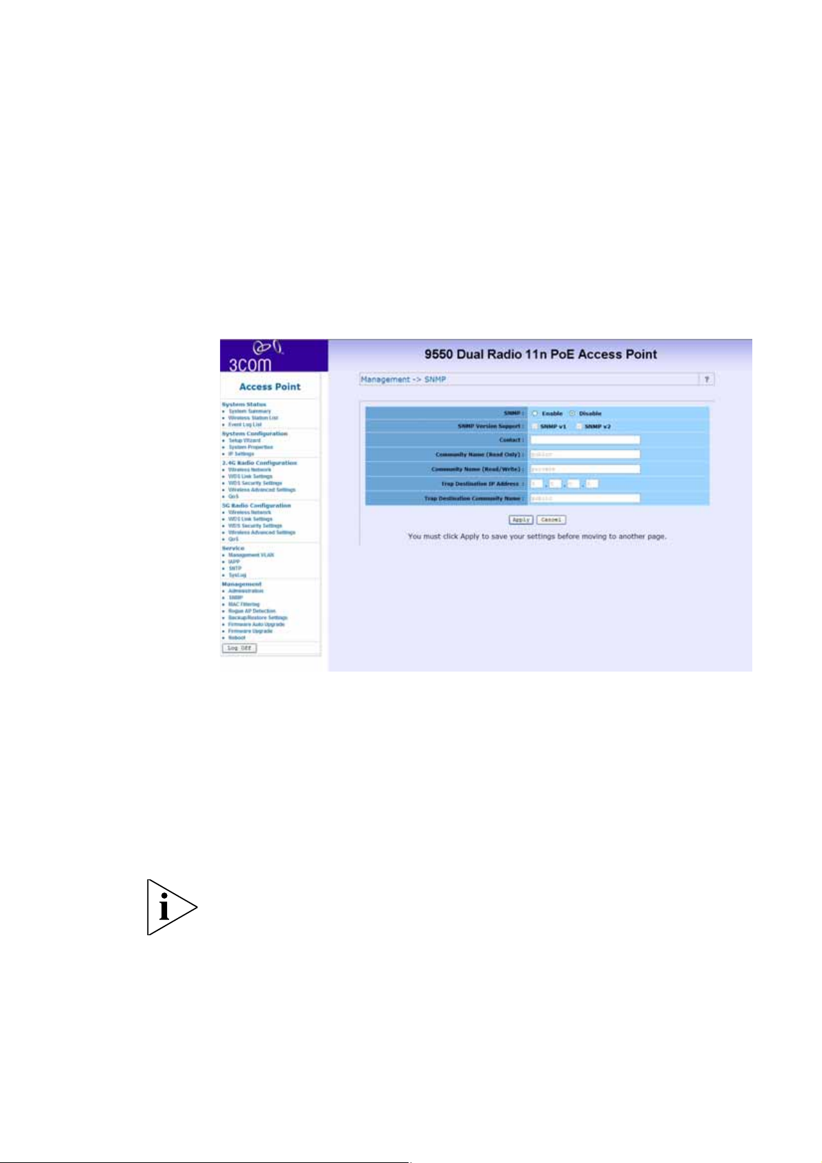
The SNMP administrative functions are changed through this
section. The following functions can be changed:
■ Enable/Disable SNMP
■ Contact info
■ Community names for read-only and read/write
■ Trap destination IP address
■ Community name
This function is not available in Wireless Bridge mode.
Page 66
62 Management
MAC Filtering
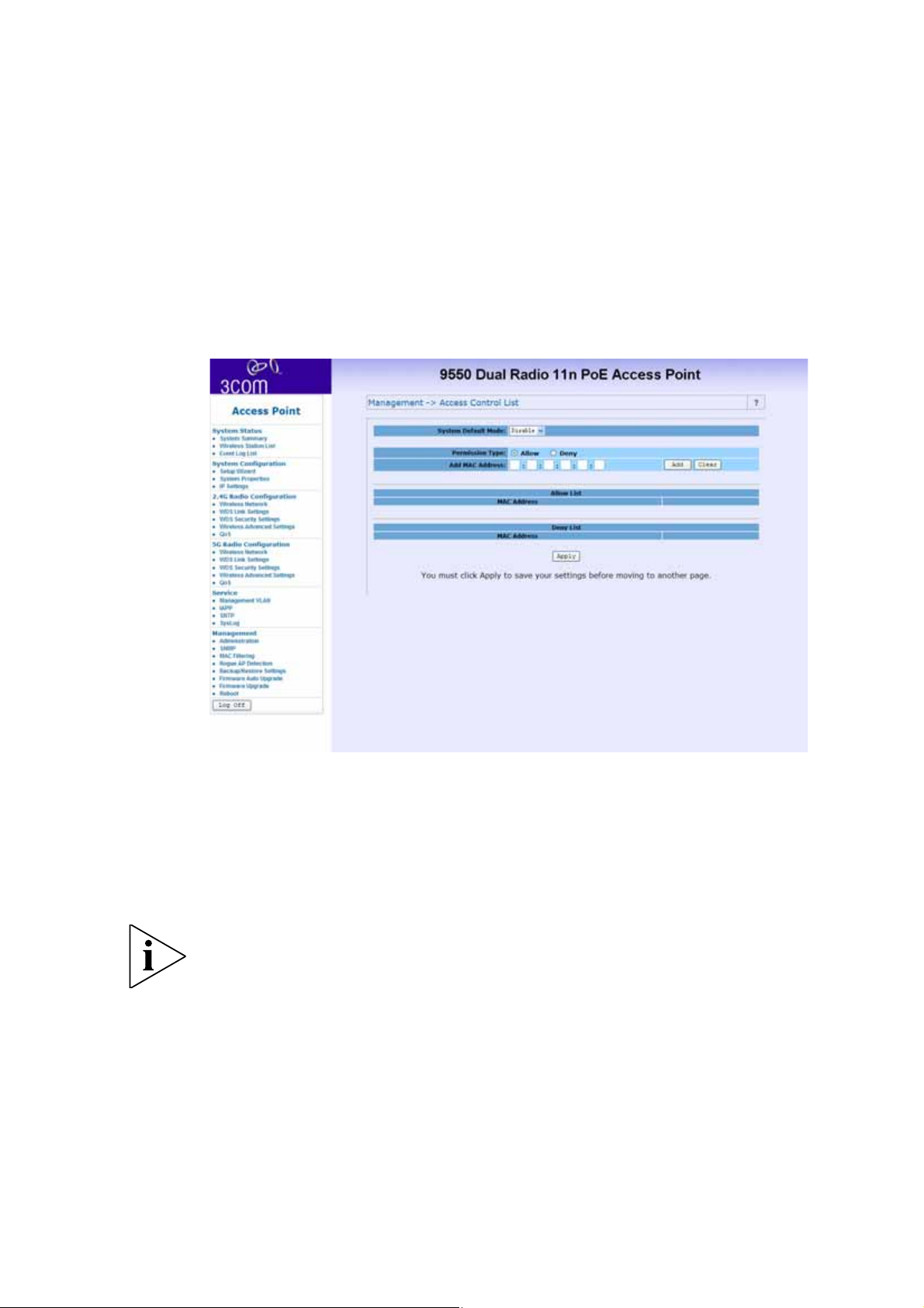
MAC filtering allows the administrator to filter MAC addresses of
network cards that can access the access point.
■ Enable/Disable filter
■ Change filter rule to allow or deny
■ Add/delete MAC addresses in the filter table
This function is only available in AP mode.
Page 67
Rogue AP Detection
Management 63
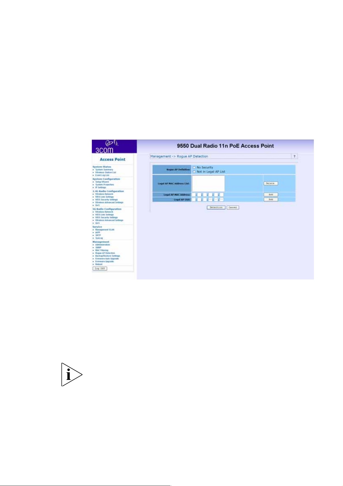
Unspecified Access Points may try to access the network through
this device. Rogue AP detection can prevent this.
■ Change Rogue AP definition.
■ Legal AP list - The list of allowed access points.
■ Detect rogue AP – All channels are scanned and Access
Points without security, or not in legal AP, are considered
rogue.
This function is only available in AP mode.
Page 68
64 Management
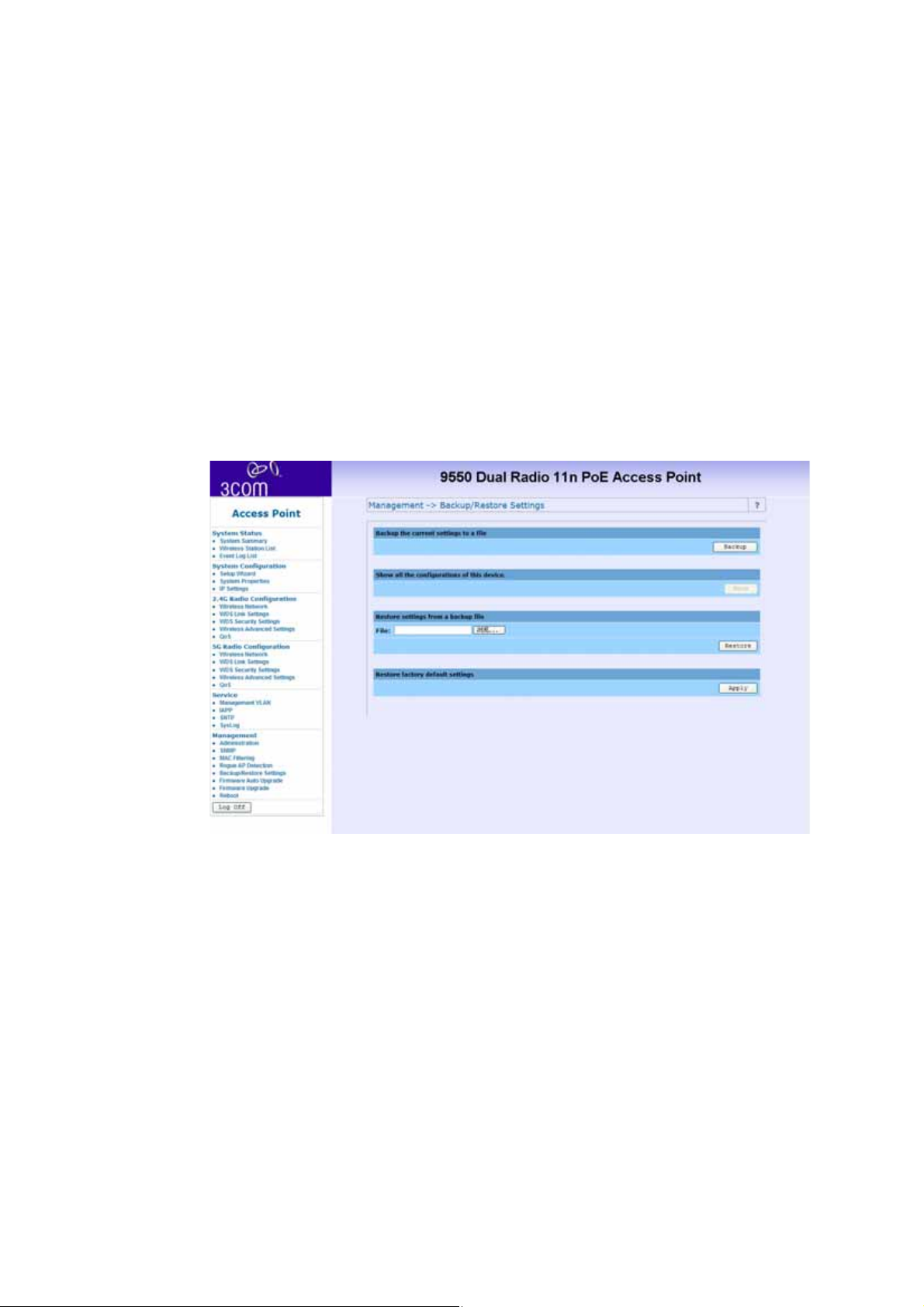
Backup/ Restore Settings
This section allows the user back up the Access Point’s current
settings and restore back to the factory default. Once you have
the Access Point working properly you should back up the
information to have it available if something goes wrong.
Page 69
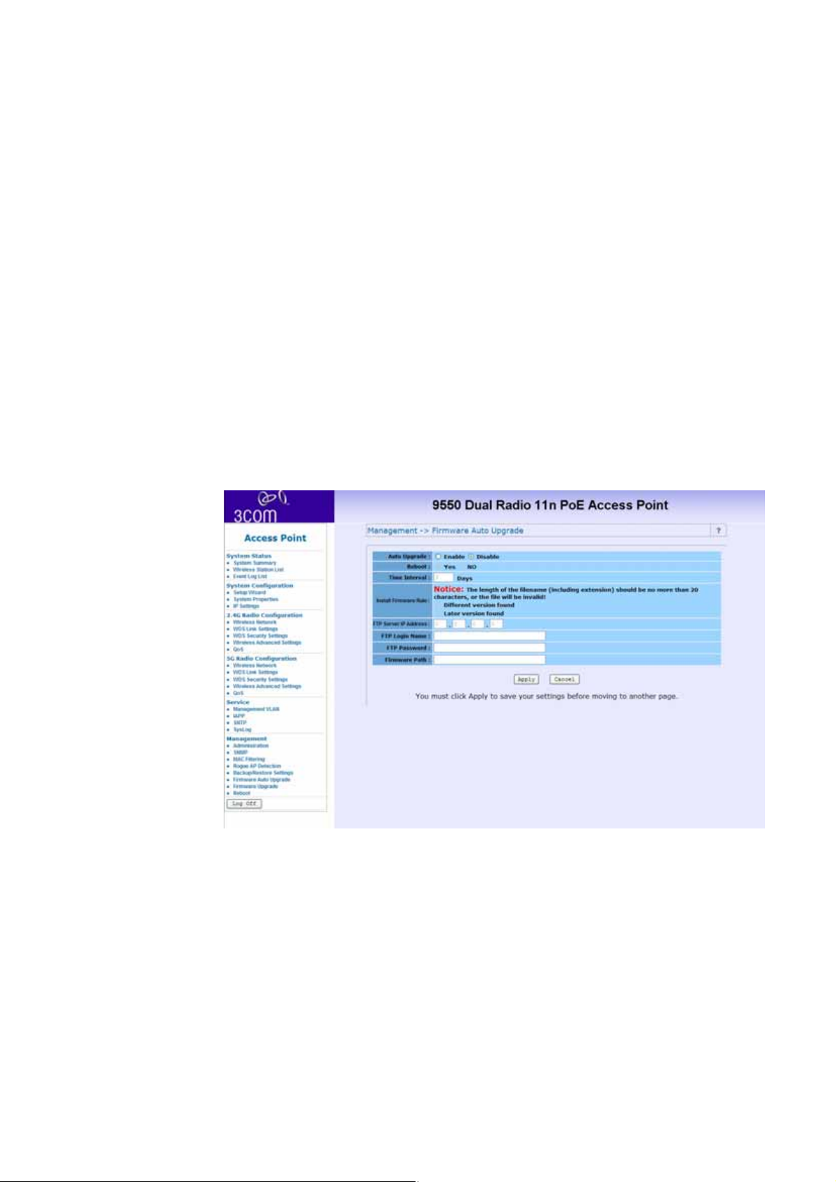
Firmware Auto Update
The Wireless Access Point can auto upgrade the firmware if there
is a newer version available. If you enable the Auto Upgrade
function, the Wireless Access Point will automatically check for
an updated version of firmware in the assigned FTP server for
each time interval assigned. Remember to insert the correct FTP
server IP address, username, password and correct path to the
FTP server.
Management 65
Page 70
66 Management
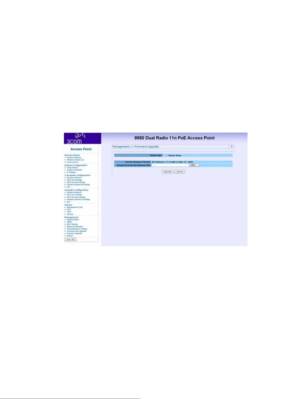
Firmware Upgrade
In this section, you can see the current firmware version of your
AP. You can also manually upgrade your firmware by entring the
path to your new firmware file.
Page 71
Management 67
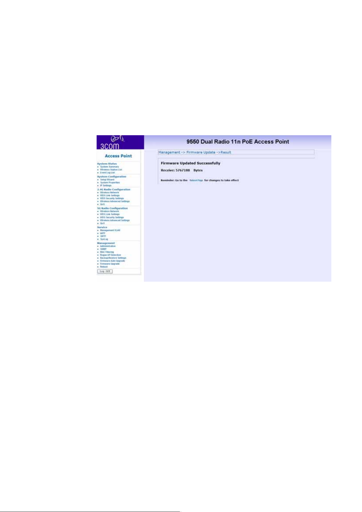
Once you have chosen the upgrade file click upgrade.
Page 72
68 Management
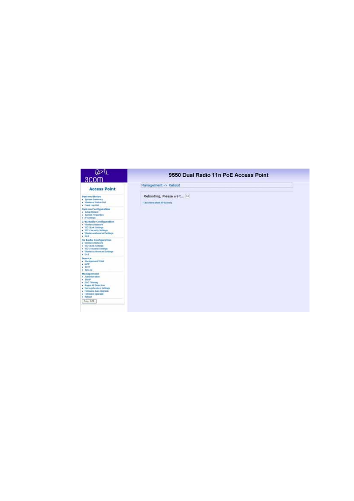
Rebooting
You can reboot the Wireless access point from the browser
interface.
After you click reboot the following window will be displayed.
After rebooting, the login page will automatically be displayed.
Page 73

Connecting through the Com Port 69
Connecting through the Com Port
Instead of using an IP address to configure the Access Point a
Null modem cable, connected to the RJ-45 Console Port, can be
used.
In your terminal settings ensure that the following configuration
is met:
Bits per Second – 9600
Data Bits – 8
Parity – None
Stop bits – 1
Flow Control - none
Once connected enter the user name and password. The default
values are as follows:
■ Username: admin
■ Password: password
Once logged in, type”?” for a list of commands.
Page 74
70 Restoring factory settings
Restoring factory settings
The Access Point can be reset to the default factory settings either
through the web browser (see “Backup/ Restore Settings” on
page 64) or manually.
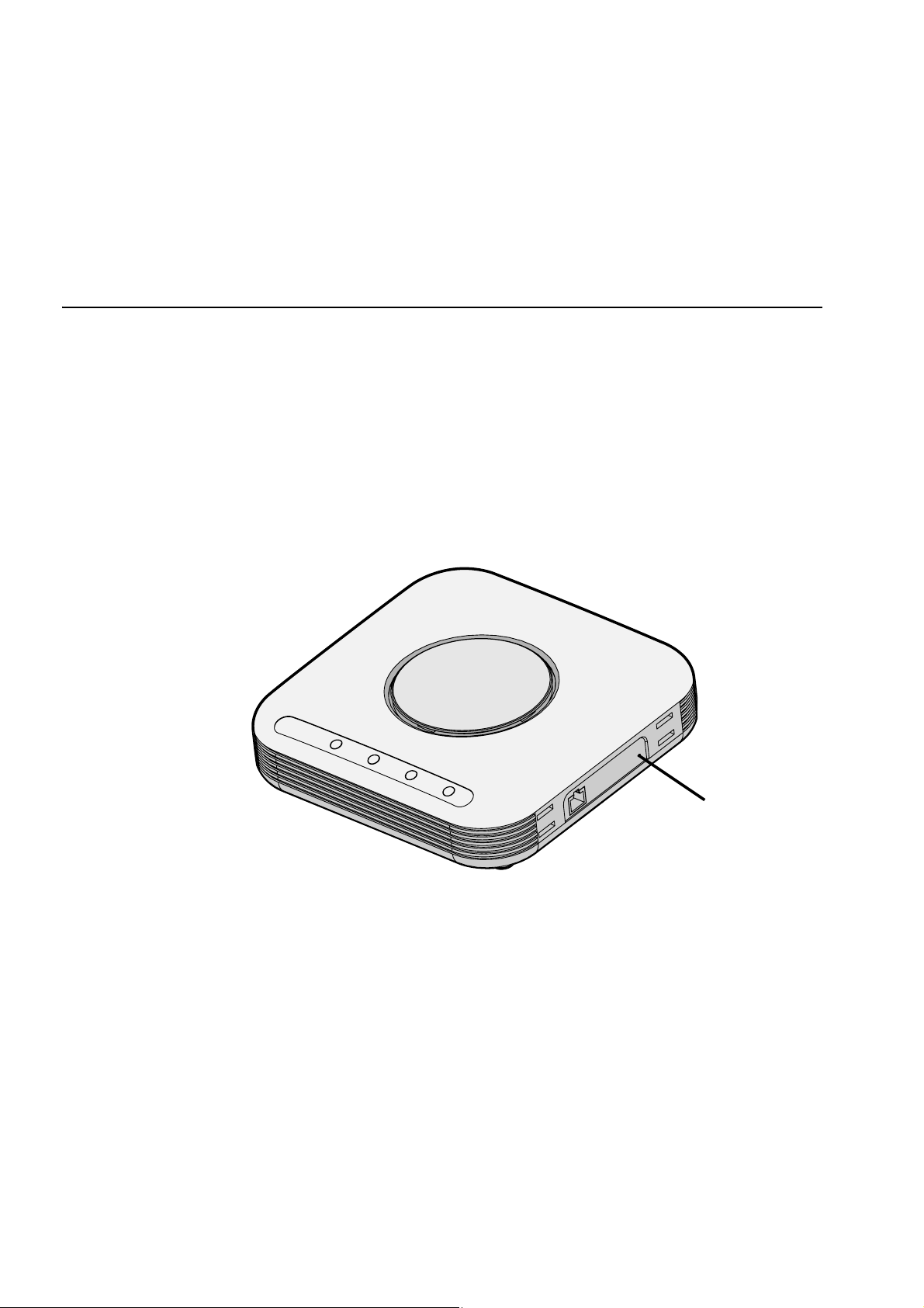
To restore the settings manually, insert a pointed object (such as
the end of a straightened paper clip) into the reset hole on the
side of the Access Point, and hold for five seconds.
Reset Hole
Page 75

TROUBLESHOOTING
A
Diagnosing Problems
If you have difficulty with the Access point, try the solutions in
the following table.
Symptom
After you change the IP address, after you restore a backup
configuration, or after you reset the Access point to factory
Diagnosing Problems 71
defaults, the Configuration Management System stops
responding and you cannot continue configuring the Access
point. If you change the IP address and click Apply, you cannot
continue to configure the device using the old IP address.
Similarly, after you restore a backup configuration or reset the
Access point to factory defaults, the IP address setting may be
changed.
Page 76

72 Diagnosing Problems
Solution (s)
To recover from this situation and continue configuring the Access
point:
1 Close your browser.
2 Return to the 3Com Wireless Infrastructure Device Manager and
click Refresh.
3 Select the device and click Configure to start a new configuration
session and set its IP address.
Symptom
The Wireless Network Tree does not appear in the 3Com Wireless
Infrastructure Device Manager window.
Solution (s)
Verify that you are using the correct network adapter. In the
device manager window, click Choose NIC. Select the network
adapter for the network you want to scan, and click OK.
Symptom
The Access point has a yellow exclamation point (!) next to it in
the Wireless Infrastructure Device Manager.
Page 77

Diagnosing Problems 73
Solution (s)
■ The Access point is on a different subnet than the computer
attempting to configure it.
■ To recover from this situation and continue configuring the
Access point:
a Close your browser.
b Return to the 3Com Wireless Infrastructure Device Manager
and click Refresh.
c Select the device and click Configure to start a new
configuration session.
d Make sure the subnet address matches that of the computer.
Symptom
Two Access points cannot communicate in ad-hoc mode.
Solution (s)
Adjust the positions of the Access points to improve reception.
To ensure correct operation in ad-hoc mode, the settings on the
two Access points must match exactly.
Launch the Access point Configuration Management System and
make sure that the Wireless LAN Service Area, channel
selections, Data Preamble setting, and security setting are the
same on both Access points.
Page 78

74 Diagnosing Problems
Symptom
You are running Windows NT. After you connect the Access
point, your computer cannot obtain a valid IP address.
Solution (s)
The Access point configuration settings may not be compatible
with the network. If they are not, and your Windows NT computer
is set up to obtain its IP address from a DHCP server, the Access
point is unable to associate with the network to obtain the IP
address.
To work around this, set a static IP address on your computer.
Then set the Access point configuration to match the network.
When the Access point is able to associate, reset your computer to
obtain its IP address from the DHCP server. If the Access point
should also obtain its IP settings from the DHCP server, make sure
this is configured properly on the IP Network page and applied
just before ending the session.
Symptom
Disconnecting the Access point
Solution (s)
To disconnect the Access point:
CAUTION: Disconnecting the Access point ends the network
association. To avoid possible data loss, exit all networking
Page 79

Diagnosing Problems 75
applications on connected devices before you disconnect the
Access point.
a Unplug the Access point Ethernet cable from the hub or
other device.
b Unplug the Access point power cord.
Symptom
Uninstalling Software and Documentation
Solution (s)
If you want to uninstall the 3Com 11a/b/g/n Wireless Workgroup
Access point software and documentation, you can either use
the standard operating system procedure for removing programs
or use the following shortcut:
From the Windows Start menu, select Start > Programs > 3Com
Wireless > Uninstall 3Com Wireless Infrastructure Device
Manager.
When prompted to confirm, click OK.
Page 80

76 Diagnosing Problems
Symptom
Upgrading Access point Firmware.
Solution (s)
Firmware is the software that is installed on the Access Point at
the factory. Some problems can be solved by installing a new
version of the firmware.
For details on how to download a firmware update from the
3Com customer support Web site and install it on your Access
Point, see “Firmware Auto Update” on page 65 or “Firmware
Upgrade” on page 66.
Page 81

Register Your Product to Gain Service Benefits 77
OBTAINING SUPPORT FOR YOUR
B
3COM PRODUCT
3Com offers product registration, case management, and repair
services through http://eSupport.3Com.com. You must have a
user name and password to access the services, described in this
appendix.
Register Your Product to Gain Service Benefits
To take advantage of warranty and other service benefits, you
must first register your product at:
http://eSupport.3Com.com/
3Com eSupport services are based on accounts that are created
or that you are authorized to access.
Solve Problems Online
The 3Com Knowledge base helps you to troubleshoot 3Com
products. This query-based interactive tool is located at:
Page 82

78 Purchase Extended Warranty and Professional Services
http://knowledgebase.3Com.com
It contains thousands of technical solutions written by 3Com
support engineers.
Purchase Extended Warranty and Professional Services
To enhance response times or extend your warranty benefits, you
can purchase value-added services such as 24x7 telephone
technical support, software upgrades, onsite assistance, or
advanced hardware replacement.
Experienced engineers are available to manage your installation
with minimal disruption to your network. Expert assessment and
implementation services are offered to fill resource gaps and
ensure the success of your networking projects. For more
information on 3Com Extended Warranty and Professional
Services, see:
http://www.3Com.com/
Contact your authorized 3Com reseller or 3Com for additional
product and support information. See the table of access numbers
later in this appendix.
Access Software Downloads
You are entitled to bug fix / maintenance releases for the version
of software that you initially purchased with your 3Com product.
Page 83

Contact Us 79
To obtain access to this software, you need to register your
product and then use the Serial Number as your login. Restricted
Software is available at:
http://eSupport.3Com.com/
To obtain software releases that follow the software version that
you originally purchased, 3Com recommends that you buy an
Express or Guardian contract, a Software Upgrades contract, or
an equivalent support contract from 3Com or your reseller.
Support contracts that include software upgrades cover feature
enhancements, incremental functionality, and bug fixes, but they
do not include software that is released by 3Com as a separately
ordered product. Separately orderable software releases and
licenses are listed in the 3Com Price List and are available for
purchase from your 3Com reseller.
Contact Us
3Com offers telephone, Internet, and e-mail access to technical
support and repair services. To access these services for your
region, use the appropriate telephone number, URL, or e-mail
address from the table in the next section.
Page 84

80 Telephone Technical Support and Repair
Telephone Technical Support and Repair
To obtain telephone support as part of your warranty and other
service benefits, you must first register your product at:
http://eSupport.3Com.com/
When you contact 3Com for assistance, have the following
information ready:
■ Product model name, part number, and serial number
■ A list of system hardware and software, including revision
level
■ Diagnostic error messages
■ Details about recent configuration changes, if applicable
To send a product directly to 3Com for repair, you must first
obtain a return materials authorization number (RMA). Products
sent to 3Com without authorization numbers clearly marked on
the outside of the package will be returned to the sender
unopened, at the sender’s expense. If your product is registered
and under warranty, you can obtain an RMA number online at
http://eSupport.3Com.com/. First-time users must apply for a
user name and password.
Telephone numbers are correct at the time of publication. Find a
current directory of 3Com resources by region at:
http://csoweb4.3Com.com/contactus/
Page 85

C
Telephone Technical Support and Repair 81
END USER LICENSE AGREEMENT
Customer shall take all steps necessary to protect Wind River's
and its licensors' proprietary rights in the Run-Time Module and
to ensure that each Run-Time Module distributed by Customer
will be accompanied by a localized copy of an End User License
Agreement.
Such End User License Agreement shall prohibit the End User
from: (i) copying the Run-Time Module, except for archive
purposes consistent with the End User's archive procedures; (ii)
transferring the Run-Time Module to a third party apart from the
Target Application; (iii) modifying, decompiling, disassembling,
reverse engineering or otherwise attempting to derive the Source
Code of the Run-Time Module; (iv) exporting the Run-Time
Module or underlying technology in contravention of applicable
U.S. and foreign export laws and regulations; and (v) using the
Run-Time Module other than in connection with operation of
the Target Application.
In addition, the End User License Agreement shall: (i) state that
the Run-Time Module is licensed, not sold and that Customer
and its licensors retain ownership of all copies of the Run-Time
Module; (ii) expressly disclaim all implied warranties, including
Page 86

82 Telephone Technical Support and Repair
without limitation the implied warranties of merchantability,
fitness for a particular purpose, title and non-infringement; (iii)
exclude liability for any special, indirect, punitive, incidental and
consequential damages; and (iv) require that any further
distribution of the Run-Time Module be subject to the same
restrictions set forth herein.
The End User License Agreement shall also state that, with respect
to the Run-Time Module, Wind River and its licensors are third
party beneficiaries of the End User License Agreement and that
the provisions related to the Run-Time Module are made expressly
for the benefit of, and are enforceable by, Wind River and its
licensors.
Page 87
APPENDIX
D
Antennas Used per Mode
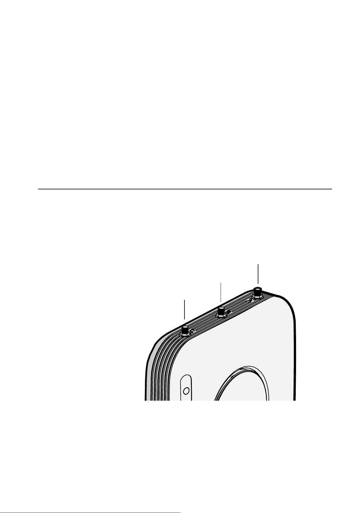
The AP has three external antenna connectors, labelled A, B and
C, as shown below.
Antennas Used per Mode 83
A
C
B
Page 88

84 Antennas Used per Mode
In some modes, not all of the connectors are in use.
The following table defines which external antenna connectors
are used in which mode:
Mode Antennas Used
2x3 A,B,C
2x2 A,C
1x1 A
Page 89
Console Cable Pin-out
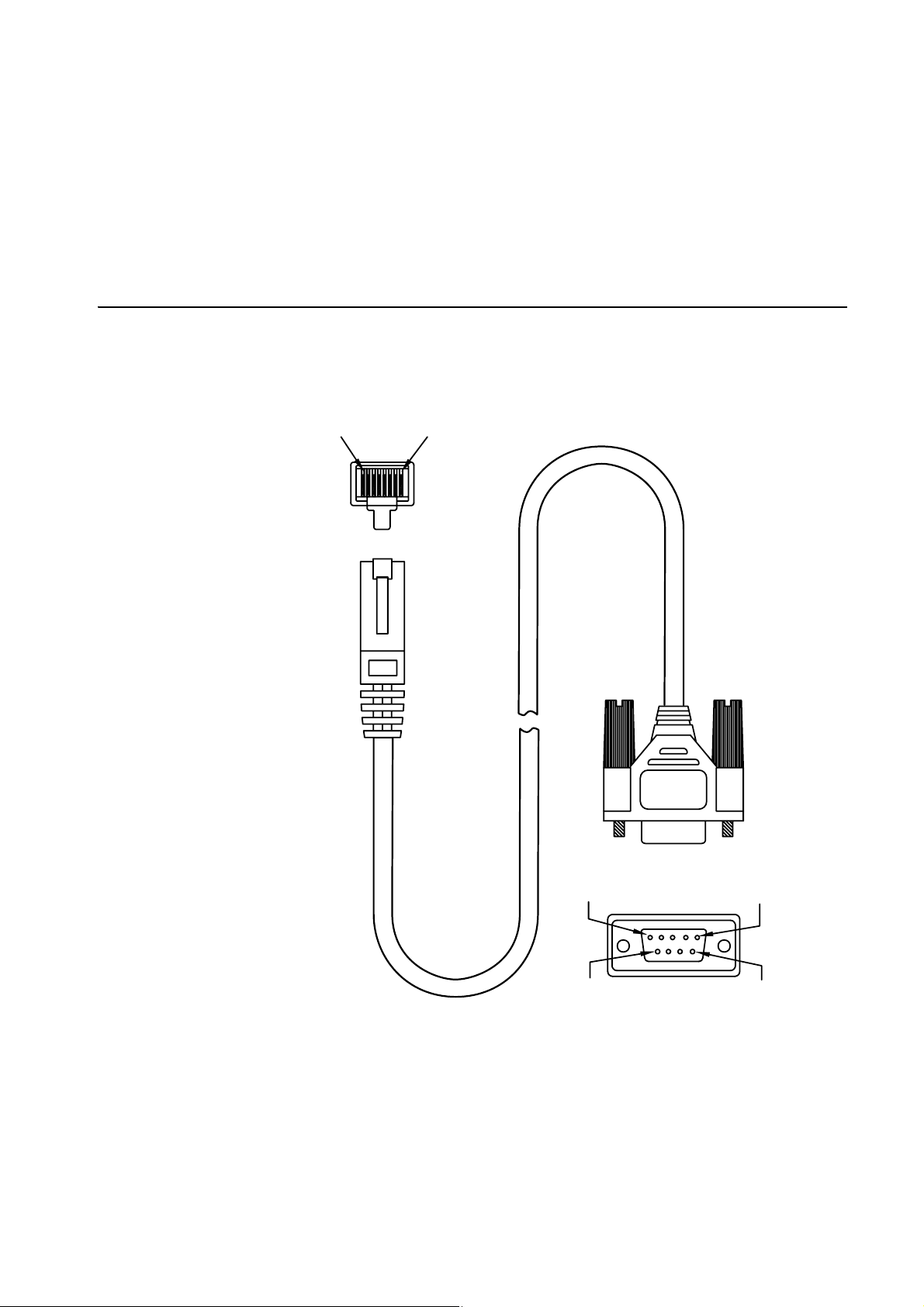
RJ45 to D-SUB 9 pin cable
81
P1
Console Cable Pin-out 85
51
P2
69
Page 90

86 Console Cable Pin-out
P1
WIRE COLOR P2
Pin no.
8 YELLOW 1
6 BROWN 2
2 GRAY 3
1 GREEN 4
5 RED 5
3 BLUE 6
4 BLACK 7
7 WHITE 8
Pin no.
Page 91

INDEX
Numerics
802.11a ...................................9
802.11b/g ..............................10
802.11d .................................50
A
Access Point mode .................35
Ad-hoc mode .........................35
Administration .......................60
Advanced Settings ..................48
Antennas Used per Mode .......83
B
Backup ...................................64
Beacon Interval .......................49
Contention .............................54
D
Data Beacon Rate ...................49
Data Rate ...............................48
default IP address ............ 24
Delivery Traffic Indication Mes-
sage .......................................49
Device Manager ... 9
DHCP Server ...........................23
DTIM ......................................49
, 23, 25, 75
, 58
F
factory settings .......................70
FAT ........................................36
BSSID .....................................41
C
Com Port ...............................69
Configuring ............................23
Console Cable ........................85
Firmware ................................76
Firmware Auto Update ...........65
Firmware Upgrade ..................66
FIT ..........................................36
Fixed Slot Time .......................54
Fragment Length ....................49
Page 92

I
IAPP ...................................... 52
Quality of Service ...................53
IEEE 802.3af .......................... 11
Installation ............................. 25
Inter-Access Point Protocol .... 52
IP Settings ............................. 37
L
LED Indicators ........................ 21
login ................................ 24
, 28
M
MAC Filtering ........................ 62
Management VLAN ............... 51
P
package contents .................. 13
Password ...................24
password ............................... 60
PoE .......................................... 9
Power over Ethernet ................ 9
, 28, 69
R
Rebooting ..............................68
Repeater mode ...................... 35
Restore ..................................64
Rogue AP Detection ...............63
RTS Threshold ........................49
S
Security ....................................8
Setting Up ..............................31
Simple Network Management Pro-
tocol ...................................... 61
Simple Network Time Protocol 56
SNMP ..................................... 61
SNTP ...................................... 56
SSID .................................32
Suppressed SSID ..................... 41
System Properties ................... 35
System Summary .................... 29
, 40
Q
QoS ....................................... 53
T
terminal settings .................... 69
Transmit Power ......................49
Page 93

U
Username ...............................69
V
VLAN ID .................................41
W
Wall Mounting .......................17
WDS ......................................45
WDS Security .........................47
WEP .......................................42
Wi-Fi Protected Access ...........43
Wired Equivalent Privacy .........42
wireless client .........................35
Wireless Distribution System ...45
Wireless Network Standards .....9
wireless range ........................16
WPA ......................................43
WPA2 ....................................44
Page 94

Federal Communication Commission Interference Statement
This equipment has been tested and found to comply with the limits for a Class B digital device, pursuant to Part 15 of
the FCC Rules. These limits are designed to provide reasonable protection against harmful interference in a
residential installation. This equipment generates, uses and can radiate radio frequency energy and, if not installed
and used in accordance with the instructions, may cause harmful interference to radio communications. However,
there is no guarantee that interference will not occur in a particular installation. If this equipment does cause harmful
interference to radio or television reception, which can be determined by turning the equipment off and on, the user is
encouraged to try to correct the interference by one of the following measures:
z Reorient or relocate the receiving antenna.
z Increase the separation between the equipment and receiver.
z Connect the equipment into an outlet on a circuit different from that to which the receiver is connected.
z Consult the dealer or an experienced radio/TV technician for help.
This device complies with Part 15 of the FCC Rules. Operation is subject to the following two conditions: (1) This
device may not cause harmful interference, and (2) this device must accept any interference received, including
interference that may cause undesired operation.
FCC Caution: Any changes or modifications not expressly approved by the party responsible for compliance could
void the user's authority to operate this equipment. This device and its antenna(s) must not be co-located or operating
in conjunction with any other antenna or transmitter.
IMPORTANT NOTE:
FCC Radiation Exposure Statement:
This equipment complies with FCC / IC RSS-102 radiation exposure limits set forth for an uncontrolled environment.
This equipment should be installed and operated with minimum distance 20cm between the radiator & your body.
Canada C Request
"Operation is subject to the following two conditions: (1) this device may not cause interference, and (2) this device
must accept any interference, including interference that may cause undesired operation of the device."
"To reduce potential radio interference to other users, the antenna type and its gain should be so chosen that the
equivalent isotropically radiated power (EIRP) is not more than that required for successful communication"
"This device has been designed to operate with an antenna having a maximum gain of 18 dBi. Antenna having a
higher gain is strictly prohibited per regulations of Industry Canada. The required antenna impedance is 50 ohms."
“To reduce potential radio interference to other users, the antenna type and its gain should be so chosen that the
equivalent isotropically radiated power (e.i.r.p.) is not more than that permitted for successful communication.”
The County Code Selection feature is disabled for products marketed in the US/Canada
This Class [B] digital apparatus complies with Canadian ICES-003.
Cet appareil numérique de la classe [B] est conforme à la norme NMB-003 du Canada.
Page 95

FCC NOTICE: To comply with FCC part 15 rules in the United States, the system must be professionally installed
to ensure compliance with the Part 15 certification. It is the responsibility of the operator and professional i nstaller
to ensure that only certified systems are deployed in the United States. The use of the system in any other
combination (such as co-located antennas transmitting the same information) is expressly forbidde n.
Only the antennas listed below are allowed to be used with the radio.
Ant.
Antenna
Type
1 Omni Ant
2 Omni Ant
3 Panel Ant
4 Panel Ant
5 Panel Ant
6 Monopole Ant
Model Name Product description
3CWE591 3Com® 6dBi Dual-Band Omni Antenna 6
TGX-102XNXXX Joymax Base Station Antenna 6
3CWE596 3Com® 18dBi Dual-Band Panel Antenna 18
3CWE598 3Com® 8dBi Dual-Band Panel Antenna 8
CUSHCRAFT Tri-mode, dual band
SL24513P12SMF
3CWE590 3Com 2dBi Dual-Band Omni Antenna Kit 2
802.11b/a/g ceiling mounted
Omnidirectional panel antenna
2.4 GHz
Gain (dBi)
3
Tx/Rx mode
1T1R
1T1R
2T2R
2T2R
2T2R
2T3R
PCB
7
TFF-A015MPAX-361 Integrated PCB Antenna 3
2T3R
Antenna
 Loading...