

Page 1

HP vp6200 Series
Digital Projector
User’s Guide
Page 2

Notice
© Copyright 2004 Hewlett-Packard Development Company, L.P.
The information contained herein is subject to change without notice. The only
warranties for HP products and services are set forth in the express warranty
statements accompanying such products and services. Nothing herein should be
construed as constituting an additional warranty. HP shall not be liable for technical
or editorial errors or omissions contained herein. Reproduction, adaptation, or
translation without prior written permission is prohibited exc ep t as allowe d under
the copyright laws.
Consumer transactions in Australia and the United Kingdom: The above
disclaimers and limitations shall not apply to consumer transactions in Australia
and the United Kingdom and shall not affect the statutory rights of consumers.
Hewlett-Packard Company
Digital Projection and Imaging
1000 NE Circle Blvd.
Corvallis, OR 97330
Second Edition October 2004
Page 3

Contents
1. Safety Instructions................................... 5
2. Introduction.............................................. 7
Projector Features ................................................... 7
Shipping Contents ................................................... 8
Accessories ............................................................. 9
Projector Exterior View ............................................ 9
Front / Upper Side ..........................................................................9
Rear Side ........................................................................................9
Connector Panel ...........................................................................10
Controls and Functions .......................................... 11
Projector ....................................................................................... 11
Remote Control ............................................................................12
Aiming the Remote Control .......................................................... 13
Replacing the Battery in the Remote Control ...............................13
3. Installation ............................................. 14
Choosing a Location .............................................. 14
Adjusting the Height .............................................. 15
Screen Size ........................................................... 15
4. Connection ............................................ 17
Connecting to a Laptop or Desktop Computer ...... 17
Connecting Component-Video Devices ................. 17
Connecting S-Video Devices ................................. 18
Connecting Composite-Video Devices .................. 18
Connecting to Display Devices .............................. 19
5. Operation............................................... 20
Startup ................................................................... 20
Shutdown ............................................................... 21
Source Selection ................................................... 21
Keystone Correction .............................................. 22
Auto Sync Adjustment ........................................... 23
Hide the Picture ..................................................... 23
Zoom / Focusing .................................................... 23
Picture Mode ......................................................... 24
Slide Operation ...................................................... 24
Contents 3
Page 4

Menu Operation ..................................................... 25
Using the Menus ..........................................................................25
1. Picture Menu ............................................................................ 26
2. Advanced Picture Menu ...........................................................27
3. Setup Menu ..............................................................................28
4. Advanced Setup Menu ............................................................. 29
5. Information Menu ..................................................................... 30
6. Maintenance.......................................... 31
Care of the Projector .............................................. 31
Cleaning the Lens .......................................... ... ... ........................31
Cleaning the Projector Case ........................................................31
Storing the Projector .....................................................................31
Transporting the projector ............................................................31
Lamp Information ...................................................32
Warning Messages .......................................................................32
Replacing the Lamp .....................................................................32
Indicators ...............................................................34
Power indicator .............................................................................34
Lamp indicator ..............................................................................34
Temperature indicator ..................................................................34
Updating the firmware ............................................ 34
7. Troubleshooting..................................... 35
8. Specifications ........................................ 36
Projector Specifications ......................................... 36
Timing Chart ..........................................................37
Supported Timing for PC Input .....................................................37
Supported Timing for Component-YPbPr Input ............................37
Supported Timing for Composite-Video and S-Video Inputs ........ 37
9. Dimensions............................................ 38
10. Regulation Statements........................ 39
Safety information ..................................................39
Safety Precautions .......................................................................39
Mercury Safety ............................................................................. 39
Regulatory information ........................................... 39
U.S.A. ........................................................................................... 39
Canada .........................................................................................40
Japan ............................................................................................40
Korea ............................................................................................ 40
International ..................................................................................40
Contents4
Page 5

1. Safety Instructions
Your projector is designed and tested to meet the latest standards for safety of
information technology equipment. However, to ensure safe use of this pro duct, it is
important that you follow the instructions mentioned in this manual and marked on
the product.
Warning
• To pre vent shock, do not open the cabinet. There are no user serviceable
parts inside.
• Please read this user’s manual before you operate your projector. Save
this user’s manual for future reference.
• Do not look straight at the projector lens during operation. The intense
light beam may damage your eyes.
• Refer servicing to qualified service personnel.
• Always open the lens shutter or remove the lens cap when the projector
lamp is on.
• In some countries, the line volt ag e is NOT st abl e. This projector i s desi gned to
operate safely within a mains voltage between 100 to 240 volts AC, but could
fail if power cuts or surges of ±10 volts occur. In areas where the mains
voltage may fluctuate or cut out, it is recommended that you connect
your projector through a power stabilizer, surge protector or
uninterruptible power supply (UPS).
• The lamp becomes extremely hot during operation. Allow the projector to cool
for approximately 45 minutes prior to removing the lamp assembly for
replacement.
• Do not operate lamps beyond the rated lamp life. Excessive operation of
lamps beyond the rated life could cause them to break on rare occasions.
• Never replace the lamp assembly or any electronic components unless the
projector is unplugged.
• Do not place this product on an unst able cart, st and, or table. The product may
fall, sustaining serious damage.
• To reduce the risk of electric shock, do not disassembl e th is app liance. Take it
to a qualified technician when service or repair is required. Incorrect
reassembly can cause malfunction of the projector or electric shock when the
appliance is subsequently used.
• This product is capable of displaying inverted images for ceiling mount
installation. Use the HP L1704A ceiling mount for moun ting the unit and
ensure it is securely installed.
1. Safety Instructions 5
Page 6

• Do not block the ventilation holes.
- Do not place this unit on a blanket, bedding or any other soft surface.
- Do not cover this unit with a cloth or any other item.
- Do not place inflammables near the projector.
If the ventilation holes are seriously obstructed, overheating inside the unit may
result in damage.
• Do not place this unit in any of the following environ ments.
- Space that is poorly ventilated or confined. Allow at least 50 cm clearance from
walls and free flow of air around the projector.
- Locations where temperatures may become excessively high, such as the inside of
a car with all windows rolled up.
- Locations where excessive humidity, dust, or cigarette smoke may contaminate
optical components, shortening the projector’s life span and darkening the image.
- Locations near fire alarms
- Locations with an ambient temperature above 35°C / 95°F
• Always place the unit on a level, horizontal surface during operation.
• Do not stand the unit on end vertica lly. Doing so may cause the unit to fall over,
causing injury or resulting in damage to the unit.
• Do not step on this unit or place any object s upon it. Besid es probable physical
damage to the unit, doing so may result in accidents and possible injury.
• Do not place liquids near or on the projector. Liquids spilled into the projector
may cause it to fail. If the projector does become wet, disco nnect it from the
power supply’s wall socket and contact HP to have the projector serviced.
1. Safety Instructions6
Page 7

2. Introduction
Projector Features
The projector integrates high-performance projection and a user-f riendly design to
deliver high reliability and ease of use.
The projector offers the following features:
• Compact and portable unit
• High quality manual zoom lens
• One-key auto-adjustment to display the best picture quality
• Digital keystone correction to correct distorted images
• Adjustable color balance control for data/video display
• Ultra-high brightness projection lamp
• Ability to display 16.7 million colors
• Switchable normal and Economic modes to reduce the power consumption
• Powerful AV function
• HDTV compatibility
Note: The apparent brightness of the projected image will vary depending on the ambient
lighting conditions and contrast/brightness settings.
2. Introduction 7
Page 8
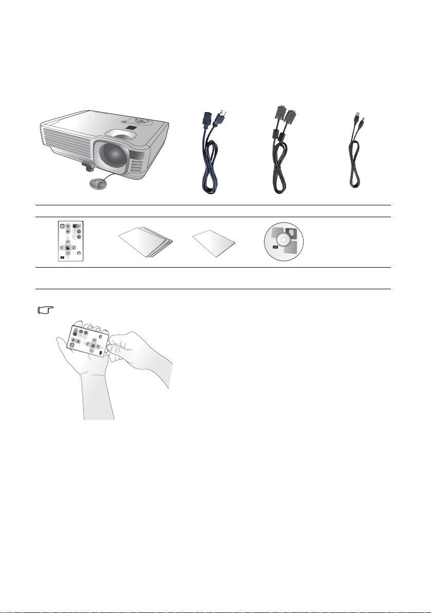
Shipping Contents
The projector is shipped with the cables required for connection to a PC. Carefully
unpack and verify that you have all of the items shown below. If any of these items
are missing, please contact your place of purchase.
Projector
Remote Control
Pull the tab before using the remote control.
Warranty and
Support
Power cord VGA cable USB Cable
Quick Setup Guide User’s Guide CD
2. Introduction8
Page 9
Accessories
Get more from your presentations with HP projector accesso ries. You can purchase
accessories at www.hp.com or through your projector dealer.
• HP ceiling mount kit enables you to simply and d isc re etly i nstall your projector
on the ceiling.
• HP mobile screens with built-in handles are easy to carry and set up anywhere
you need them.
• HP premium remote control allows you to control every aspect of your
presentation.
• HP power cables allow you to connect in any region.
• HP cables allow you to connect all audio-video equipment.
• HP replacement lamp brings your projector up to factory-fresh brightness.
Projector Exterior View
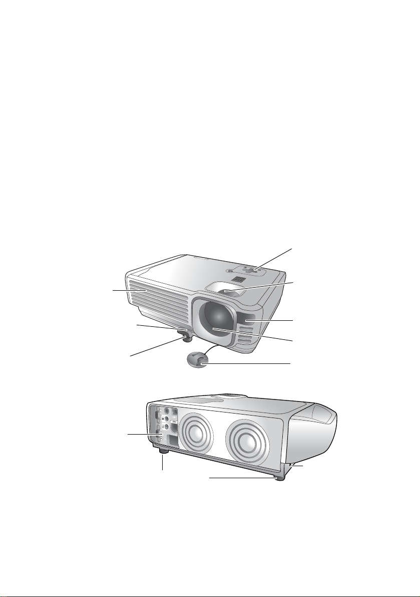
Front / Upper Side
Control panel
(See page 11 for
detailed information.)
Focus ring and
Ventilation grill
Zoom ring
Front adjuster button
Front adjuster foot
Rear Side
Connector panel
(See page 10 for
more information.)
Front IR remote
sensor
Projection lens
Lens cap
Kensington lock slot
Rear adjusters foot
2. Introduction 9
Page 10
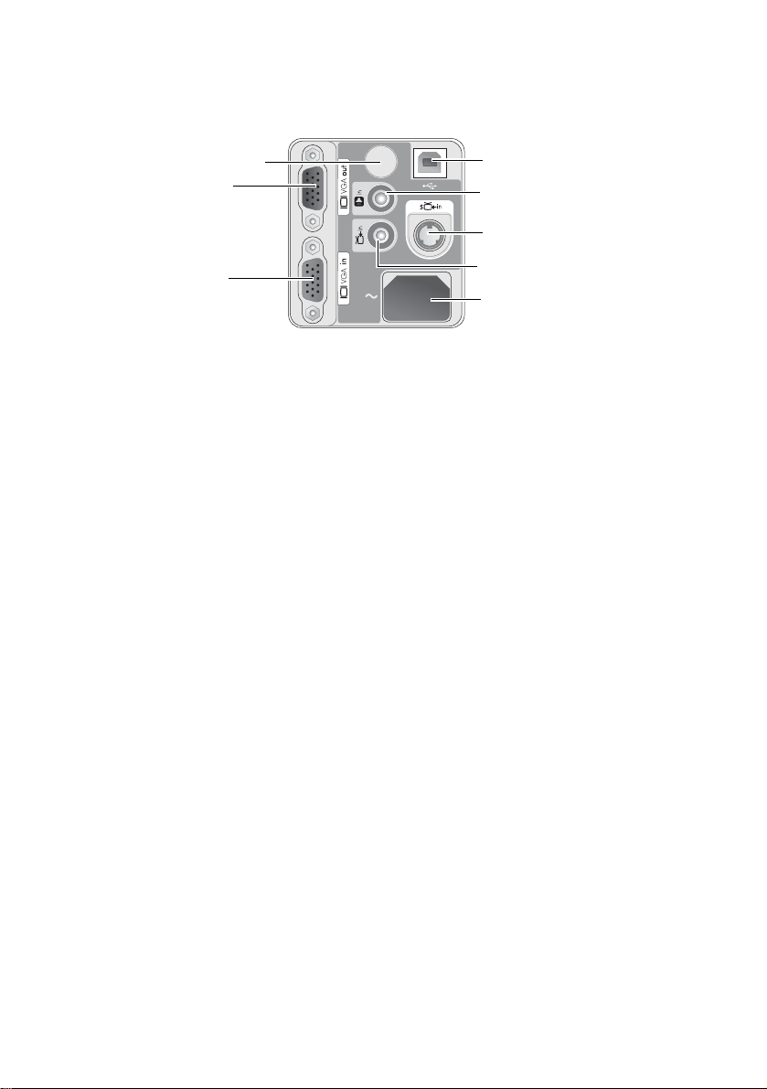
Connector Panel
Refer to page 17 for more information on making connections to various equipment.
IR remote sensor
VGA output
VGA input
(PC/ YPbPr/ YCbCr)
USB output
Audio input
S-Video input
Composite-video input
Power cord socket
2. Introduction10
Page 11
Controls and Functions
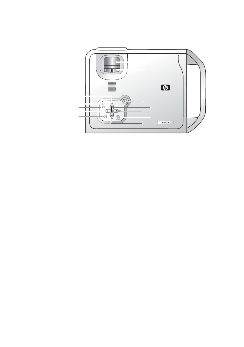
Projector
6
7
5
4
3
2
1
8
9
10
11
12
1. Hide button (Refer to page 23 for more information.)
Hides the display.
2. Source button (Refer to page 21 for more information.)
Switches to the next input source. Cycles through VGA, composite video, and
S-video inputs.
3. Temperature-warning light (Refer to page 34 for more information.)
Turns on when the internal temperature is too hi g h.
4. Lamp-warning light (Refer to page 32 for more information.)
Turns on when lamp fails.
5. Keystone buttons (Refer to page 22 for more information.)
Adjust the picture to eliminate slanted sides.
6. Focus ring
Adjusts the focus of the picture.
7. Zoom ring
Adjusts the size of the picture.
8. Power button (Refer to pages 20 and 21 for more information.)
Turns the projector on or off.
9. Menu button and directional arrows (Refer to page 25 for more informa-
tion.)
Change projector settings using the on-screen menu.
10. Auto sync button (Refer to page 23 for more information.)
Resynchronizes the projector to a PC input signal.
11. Picture mode button (Refer to page 24 for more information.)
Adjusts the picture so it is optimized for different types of inputs.
12. Keystone buttons (Refer to page 22 for more information.)
Adjust the picture to eliminate slanted sides.
2. Introduction 11
Page 12
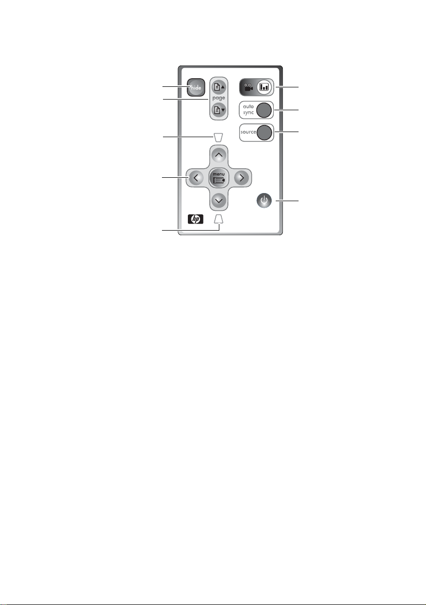
Remote Control
56
4
7
3
8
2
9
1
1. Keystone button (Refer to page 22 for more information.)
Adjust the picture to eliminate slanted sides.
2. Menu button and directional arrows (Refer to p age 25 for more information.)
Change projector settings using the on-screen menu.
3. Keystone button (Refer to page 22 for more information.)
Adjust the picture to eliminate slanted sides.
4. Page-up and page-down buttons ( Refer to page 24 for more information.)
Scroll up and down through pages on a connected PC.
5. Hide button (Refer to page 23 for more information.)
Hides the display.
6. Picture mode button (Refer to page 24 for more information.)
Adjusts the picture so it is optimized for different types of inputs.
7. Auto sync button (Refer to page 23 for more information.)
Resynchronizes the projector to a PC input signal.
8. Source button (Refer to page 21 for more information.)
Switches to the next input source. Cycles through VGA, composite vid eo, and
S-video inputs.
9. Power button (Refer to pages 20 and 21 for more information.)
Turns the projector on or off.
2. Introduction12
Page 13
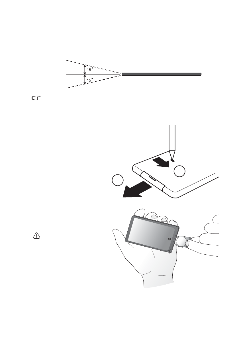
Aiming the Remote Control
Infrared (IR) remote control sensors are located on the front and the back of the
projector. The remote con trol must be held at an angl e within 30 degre es of the projection screen or the projector’s IR remote control sensors to functi on correctly. The
distance between the remote control and the sensors should not exceed 6 met ers
(19.5 feet).
6m
Notes on Remote Control Operation:
Make sure that there are no obstacles between the remote control and the IR sensors on the
projector that might obstruct the infra-red beam.
Replacing the Battery in the Remote Control
1. Using a ballpoint pen,
push and hold the battery latch toward the
center, then pull out the
battery holder .
2. Remove the old battery
from the battery holder.
1
2
3. Insert the new battery in
the holder.
4. Push the holder into the
remote control.
Avoid excessive heat and humidity.
There may be danger of an explosion if the battery is incorrectly
replaced. Replace only with the
same or equivalent type recommended by the manufacturer. Dispose of the used battery according
to the manufacturer’s instructions.
2. Introduction 13
Page 14

3. Installation
Choosing a Location
Your projector is designed to be installed in t he four installation configurations
shown here. Your room layout or personal preference will dictate which installation
configuration you use.
I. Table front II. Ceiling front
III. Table rear IV. Ceiling rear
For further information on the four configurations, please refer to page 29.
If you place the projector above or below the screen, you have to tilt it down or up to
center the image on the screen, in these situations image distortion will occur. Use
the Keystone function to correct the distortion. See pa ge 22 fo r keystone correctio n.
3. Installation14
Page 15

Adjusting the Height
The projector is equipped with 1 quick-release adjuster foot and 2 rear adjuster
feet. These adjusters change the image height and projec tion angle. To adjust the
projector,
1. Lift the projector up and
press the adjuster button
to release the adjuster.
The adjuster will drop into
position and be locked. It
can lift the projector by up
to 15 degrees.
2. Screw the rear adjuster
feet to fine tune the horizontal angle.
Press the adjuster button again
to retract the foot.
If the screen and the projector are not perpendicular to each other, the projected image
becomes trapezoidal. To correct this situation, adjust the value of Keystone in the Picture
menu, on the projector control panel or on the remote control.
Screen Size
Place the projector at the required distance from the screen according to the
required picture size (see the table on the next page).
M
a
x
i
m
u
m
z
o
o
M
i
n
m
i
m
u
m
z
o
o
m
e
c
n
a
t
s
Focus ring
i
d
n
o
i
t
c
e
j
o
r
P
Min. zoom
Max. zoom
3. Installation 15
Page 16

Screen size chart (4:3 aspect ratio)
Distance
from
screen
feet inch feet inch feet inch meter cm meter cm meter cm
4 48 2.49 29.9 3.05 36.6 1 100 0.62 62.2 0.76 76.2
6 72 3.73 44.8 4.57 54.9 1.5 150 0.93 93.3 1.14 114.3
8 96 4.98 59.7 6.10 73.2 2 200 1.24 124.5 1.52 152.4
10 120 6.22 74.7 7.62 91.4 2.5 250 1.56 155.6 1.91 190.5
12 144 7.47 89.6 9.14 109.7 3 300 1.87 186.7 2.29 228.6
14 168 8.71 104.5 10.67 128.0 3.5 350 2.18 217.8 2.67 266.7
16 192 9.96 119.5 12.19 146.3 4 400 2.49 248.9 3.05 304.8
18 216 11.20 134.4 13.72 164.6 4.5 450 2.80 280.0 3.43 342.9
20 240 12.45 149.4 15.24 182.9 5 500 3.11 311.2 3.81 381.0
22 264 13.69 164.3 16.76 201.2 5.5 550 3.42 342.3 4.19 419.1
24 288 14.94 179.2 18.29 219.5 6 600 3.73 373.4 4.57 457.2
26 312 16.18 194.2 19.81 237.7 6.5 650 4.04 404.5 4.95 495.3
28 336 17.42 209.1 21.34 256.0 7 700 4.36 435.6 5.33 533.4
30 360 18.67 224.0 22.86 274.3 7.5 750 4.67 466.7 5.72 571.5
32 384 19.91 239.0 24.38 292.6 8 800 4.98 497.8 6.10 609.6
Diagonal measurement
Minimum
zoom
Maximum
zoom
Distance
from screen
Diagonal measurement
Minimum
zoom
Maximum
zoom
Screen size chart (16:9 aspect ratio)
Distance
from
screen
feet inch feet inch feet inch meter cm meter cm meter cm
4 48 2.29 27.5 2.80 33.6 1 100 0.57 57.4 0.70 70.0
6 72 3.44 41.3 4.20 50.4 1.5 150 0.86 86.0 1.05 105.0
8 96 4.59 55.1 5.60 67.2 2 200 1.15 114.7 1.40 140.0
10 120 5.74 68.8 7.00 84.0 2.5 250 1.43 143.4 1.75 179.4
12 144 6.88 82.6 8.40 100.8 3 300 1.72 172.1 2.10 209.9
14 168 8.03 96.4 9.80 117.6 3.5 350 2.01 200.8 2.45 244.9
16 192 9.18 110.1 11.20 134.4 4 400 2.29 229.4 2.80 279.9
18 216 10.32 123.9 12.60 151.2 4.5 450 2.58 258.1 3.15 314.9
20 240 11.47 137.7 14.00 167.9 5 500 2.87 286.8 3.50 349.9
22 264 12.62 151.4 15.39 184.7 5.5 550 3.15 315.5 3.85 384.9
24 288 13.77 165.2 16.79 201.5 6 600 3.44 344.1 4.20 419.9
26 312 14.91 179.0 18.19 218.3 6.5 650 3.37 372.8 4.55 454.9
28 336 16.06 192.7 19.59 235.1 7 700 4.02 401.5 4.90 489.8
30 360 17.21 206.5 20.99 251.9 7.5 750 4.30 430.2 5.25 524.8
32 384 18.35 220.3 22.39 268.7 8 800 4.59 458.9 5.60 559.8
Diagonal measurement
Minimum
zoom
Maximum
zoom
Distance
from screen
Diagonal measurement
Minimum
zoom
Maximum
zoom
There is 3% ~ 5% tolerance among these numbers due to optical component variations.
3. Installation16
Page 17

4. Connection
When connecting a signal source to the projector, be sure to:
1. Turn all equipment off before making any connections.
2. Use the correct signal cables for each source.
3. Ensure the cables are firmly inserted.
In the connections shown below, only certain cables are included with the projector (see
page 8). Other cables are available from HP or from electronics stores.
Connecting to a Laptop or Desktop Computer
USB cable
Audio cable
VGA cable
Connecting Component-Video Devices
Audio cable
Component Video Cable
AV equipment
The projector is capable of displaying various High Definition TV display modes.
Some of these sources are:
• Digital-VHS (D-VHS) player • DVD player
• Satellite Dish HDTV receiver • Digital TV tuners
Most of these sources will provide an analog component video output, a standard
VGA output, or a YP
The projector is capable of accepting HDTV data through a Component Video connector. Use a Component Video cable (an optional accessory) to display these
images.
The following standards are supported in the HDTV function:
• 480i • 480p
• 576i • 576p
• 720p (50/ 60 Hz) • 1080i (50/ 60 Hz)
bPr (default) format.
YPbPr
VGA
4. Connection 17
Page 18

Connecting S-Video Devices
Audio cable
S-Video cable
Connecting Composite-Video Devices
Audio cable
Composite -video cable
If the selected video image is not displayed after the projector is turned on and the correct
video source has been selected, check that the video source is turned on and operating correctly. Also check that the signal cables have been connected correctly.
4. Connection18
Page 19

Connecting to Display Devices
If you want to monitor your presentation close-up on a monitor as well as on the
screen, you can connect the VGA signal output port on the projector to an external
monitor with a VGA cable.
VGA cable
4. Connection 19
Page 20

5. Operation
Startup
1. Switch all of the connected equipment on.
2. Plug the power cord into the projector and into a wall socket.
3. Turn on the wall socket switch (where fitted).
4. Press Power on the remote control or projector to start the unit. The Power
button flashes during warm up, then turns on solid.
5. The projector searches the input ports for an input signal. A message on the
screen shows the ports being searched.
Y ou can also press source on the proje ctor or remote control to sele ct your desired
input signal. For more information, please refer to page 21.
If the frequency or resolution of the input signal exceeds the projector’s operating range, you
will see the message “Out of Range” displayed on a blank screen.
5. Operation20
Page 21

Shutdown
1. Press the Power button on
the projector or remote
control. The Power button
flashes and the lamp shuts
down, the fans continue to
run for approximately 2
minutes to cool down the
projector.
To protect the lamp, the projector
will not respond to any commands
during the cooling process.
2. Disconnect the power cord from the wall socket.
Do not unplug the power cord before the projector shutdown sequence is complete or during
the 2-minute cooling down process.
If the projector is not properly shut down, and you attempt to restart it soon after , the fa ns may
run for a few minutes to cool down. Press Power again to start the projector after the fans
stop.
Source Selection
To sequentially select input sources,
press source on the projector control panel or the remote control. It
may take you a few seconds when
the projector is searching for input
signals. The selected source will be
displayed at the bottom right of the
screen for 3 seconds. For a quick
search, you can also press the key
repeatedly until your desired signal is
displayed.
5. Operation 21
Page 22

Keystone Correction
Keystoning refers to the situation where the proj ected image is noticeably wider at
either the top or bottom. It occurs when the projector is not perpendicular to the
screen.
To correct this, besides adjusting the height of the projector,
you will need to manually correct it following one of these
steps.
• Press the keystone up
or keystone down
button on the remote
control or remote control
to display the status bar
labelled Keystone, then
press the keystone up
button to correct keystoning at the top of the image or press the keystone
down button to correct keystoning at the bottom of the image .
• Press the menu button on the projector or remote control. Go to
Picture > Keystone and adjust the values by pressing the left or right
button.
0
0
-6
+6
5. Operation22
Page 23

Auto Sync Adjustment
In some situations when showing a
PC display, the picture may be cut
off at the edges. To correct this,
press auto sync on the the pro jector
or remote control. Within 3 seconds,
the projector will re-adjust the values
of Frequency and Tracking to provide the best picture quality.
The current source information will
be displayed at the bottom right of
the screen for 3 seconds.
The screen will be blank while auto sync
is functioning.
Hide the Picture
In order to draw the audience’s full
attention to the presenter, you can
use hide to hide the screen image.
Press hide again to restore the
image. When this function is activated with an audio signal connected, the background sound still
can be heard.
If the picture remains hidden for a
long time, the projector automatically shuts down. To set the delay,
press menu and go to Advanced
Setup > Power timeout.
Zoom / Focusing
Adjust the projected image to your
desired size using the zoom ring. Then
focus the image by rotating the focus
ring. Refer to the screen size tables on
page 16.
Focus ring
Zoom out
Zoom in
5. Operation 23
Page 24

Picture Mode
Press the picture mode button
on the projector or remote control to
select a operation mode that suits
your need. There are several operation modes available for different
types of signals.
PC Signal Input
Graphics Vivid Video Economy
YPbPr / S-Video / Composite-Vide o Sig na l Inp ut
Gaming Video Cinema Economy
Refer to page 26 for more information.
Slide Operation
You can operate your PowerPoint presentation moving forwards and
backwards by pressing
trol.
You must connect the projector to your PC or notebook with a USB cable
prior to using this function.
Page Up and Page Down on the remote con-
5. Operation24
Page 25

Menu Operation
Using the Menus
The projector is equipped with on-screen menus for making vario us adjustments
and settings.
The following example describes the adjustment of the keystone setting.
1. Press menu on the projector or
remote control to open the onscreen menu.
2. Press the left or right button
on the projector or remote control to
select the Picture menu.
3. Press the up or down button
on the projector or remote control to
select Keystone.
4. Adjust keystone values by
pressing the left or
right button on the projector
or remote control.
5. Press the menu button on
the projector or remote control to leave and save the setting.
5. Operation 25
Page 26

1. Picture Menu
Some picture adjustments are available only when certain input ports are in use. Unavailable
adjustments are not shown on the screen.
FUNCTION DESCRIPTION
Picture mode is provided so you can optimize your projector
image set-up to suit your program type.
PC Signal Input
1. Graphics Mode: Is designed for presentations. The brightness is emphasized in this mode.
2. Vivid Mode: Is perfect for playing games. The color saturation and brightness are well-balanced.
3. Video Mode: Is suitable for cinematic enjoyment displaying
images in their natural color.
4. Economy Mode: Use this mode to reduce system noise
Picture mode
Keystone
and reduce power consumption by 20%. The lamp life is
also extended with lower light output.
YPbPr/ S-Video/ Composite-Video Signal Input
1. Gaming Mode: Is suitable for playing vi d eo ga mes in a
bright living room.
2. Video Mode: With a higher color temperature, it is suitable
for enjoying TV movies.
3. Cinema Mode: With a lower color temperat ure, it is suit able
for enjoying cinematic movies.
4. Economy Mode: Use this mode to reduce system noise
and reduce power consumption by 20%. The lamp life is
also extended with lower light output.
Corrects any keystoning of the image. Refer to page 22 for more
information.
Adjusts the brightness of the image. The higher the value, the
brighter the image. And lower the setting, darker the image.
Adjust this control so the black areas of the image appear black
but detail in the dark areas is visibl e.
Brightness
Contrast
5. Operation26
-30
50
+70
Adjusts the degree of difference between dark and light in the
image. The higher the value, the greater the contrast.
-30
50
+70
Page 27

Saturation
Tint
Increases or decreases the color intensity of the image.
Adjusts the color tones of the image. Th e h igher the value, the
more reddish the image becomes. The lower the value, the more
greenish the image becomes.
2. Advanced Picture Menu
Some picture adjustments are available only when certain input ports are in use. Unavailable
adjustments are not shown on the screen.
FUNCTION DESCRIPTION
Aspect ratio
Widescreen
input
Horizontal
Sets how the picture fits the screen.
1. Fill 2. Best fit
Sets whether a widescreen (16:9) input device is in use.
1. No 2. Yes
Adjusts the horizontal
position of the projected
image.
offset
Adjusts the vertical position of the projected
image.
Vertical
offset
-30 +30
Tracking
Frequency
Sharpness
-30
This function allows you to adjust the clock
phase to reduce image distortion.
Adjusts the horizontal width of the image.
Adjusts the image to make it look sharper or softer.
+30
5. Operation 27
Page 28

3. Setup Menu
FUNCTION DESCRIPTION
Turns sound on or off.
Mute
Volume
Not muted
Adjusts the volume level.
Muted
Timeout for
menu
Reset all
settings
Color
temperature
Sets the length of time the OSD will remain active after your last
button press. The range is from 5 to 100 seconds.
Returns all settings to the factory preset values.
Adjusts the appearance of white.
1. Cool: Makes images appear bluish white.
2. Neutral: Maintains normal colorings for white.
3. Warm: Makes images appear reddish white.
5. Operation28
Page 29

4. Advanced Setup Menu
FUNCTION DESCRIPTION
The projector can be installe d on a ceiling or behind a screen, or
with one or more mirrors.
Table front: Select this setting
with the projector set on the
floor and audience viewing the
projected images from the
front side of the screen. This is
the most common setting.
Ceiling front: Select this setting with the projector suspended from the ceiling and
audience viewing the pro-
Projector
position
jected images from the front
side.
Table rear: Select this setting
when the projector is placed
near the floor and behind the
screen. A special rear projection screen is required.
Ceiling rear: Select this setting
when the projector is suspended from the ceiling and
placed behind the screen. A
special rear projection screen
is required.
Power
timeout
Scan inputs
Language
Password
Change
password
Determines the length of time before the projector wi ll automatically shut down when the picture is hidden.
Sets whether the projector searches automa tically for input sign als.
If scanning is on, the projector will scan for input signals in the following order: VGA/YPbPr --> Composite-video --> S-Video until it
acquires a signal. If the function is not activated, the projector
selects the last input signal.
Sets the language for the on-screen menus.
Sets whether a password is required to turn on the projector.
Sets or changes the current password.
5. Operation 29
Page 30

5. Information Menu
This menu shows you the current operating status of the projector.
5. Operation30
Page 31

6. Maintenance
Care of the Projector
Your projector needs little maintenance. Keep it clean for best performance.
Never remove any parts of the projector except the lamp. Cont act your dealer if
other parts needs replacing.
Cleaning the Lens
Clean the lens whenever you notice dirt or dust on the surface.
Use a canister of compressed air to remove dust.
If there is dirt or smears, use lens-cleaning paper or moisten a soft cloth with lens
cleaner to gently wipe the lens surface.
Never rub the lens with abrasive materials.
Cleaning the Projector Case
Before you clean the case, turn the projector off and unplug the power cord.
To remove dirt or dust, wipe the case with a soft, dry, lint-free cloth.
To remove stubborn dirt or stains, moisten a soft cloth with water and a neutral
detergent. Then wipe the case.
Never use wax, alcohol, benzene, thinner or other chemical detergents. These can damage the
case.
Storing the Projector
If you need to store the projector for an extended time, please follow the instructions below.
Make sure the temperature and humidity of the storage area are within the
recommended range for the projector. Please refer to page 36 in the manual.
Retract the adjuster feet.
Remove the batteries from the remote control.
Pack the projector in its original packing or equivalent.
Transporting the projector
It is recommended that you ship the projector with it s original p acking or equi valent.
6. Maintenance 31
Page 32

Lamp Information
Warning Messages
When the Lamp indicator lights up red o r a message appears sugg esting it is t ime
to replace the lamp, please install a new lamp or consult your dealer. An old lamp
may cause a malfunction in the projector and in some instances the lamp may
break.
For more detailed information on the la m p ind i ca t or, please refer to page 34.
The Lamp indicator light and Temperature warning light will light up if the lamp becomes too
hot. Turn the power off and let the projector cool for 45 minutes. If the Lamp or Temp indicator
still lights up after turning the power back on, please contact your dealer.
The following Lamp warning messages will remind you to change the lamp.
Message Status
Lamp is getting old.
Buy a spare lamp.
End of lamp life
Install a new lamp.
Then hold [V] to reset lamp hours.
Replacing the Lamp
To reduce the risk of electrical shock, always turn the projector off and disconnect the power
cord before changing the lamp.
To reduce the risk of severe burns, allow the projector to cool for at least 45 minutes before
replacing the lamp.
To reduce the risk of injuries to fingers and damage to internal components, use caution when
removing lamp glass that has shattered into sharp pieces.
To reduce the risk of injuries to fingers and/or compromising image quality by touching the
lens, do not touch the empty lamp compartment when the lamp is removed.
The lamp contains a small amount of mercury. If the lamp breaks, adequately ventilate the area
where the breakage occurred. Disposal of this lamp might be regulated due to environmental
considerations. For disposal or recycling information, contact your local authorities or the
Electronic Industries Alliance (http://www.eiae.org).
1. Turn off the projector.
2. After the power button stops flashing, unplug the power cord from the wall
socket.
3. Turn the projector over. Then loosen the
screws and remove the lamp cover. If the
lamp is hot, avoid burns by waiting for 45
minutes until the lamp has cooled.
The lamp has been in operation for a
long time, and you should have a spare
lamp available. For optimal performance, install a new lamp.
The lamp has reached the end of its life,
and the projector will not operate normally until you change the lamp.
6. Maintenance32
Page 33

4. Loosen the screw that holds the lamp to the
projector. If the screw is not loosened completely, they could injure your fingers. It is
strongly recommended that you use a magnetic-head screwdriver.
5. Slide the latch to release the lamp.
6. Lift the handle so that it st ands up. Use t he
handle to slowly pull the lamp out of the
projector.
Pulling it too quickly may cause the lamp to break and
scatter broken glass in the projector.
Do not place the lamp in locations where water might
splash on it, children can reach it, or near flammable
materials.
Do not insert your hands into the projector after the
lamp is removed. If you touch the optical components
inside, it could cause color unevenness and distortion
of the projected images.
7. Insert a new lamp. Make sure the handle is
fully locked and tighten the screw firmly.
Slide the latch so it holds the lamp.
If the screw is loose, it could result in a malfunction.
Do not over tighten the screw.
8. Re-install the lamp cover and tighten the
screw. Do not turn the power on with the
lamp cover removed.
9. Plug in the projector and turn it on.
10. Unplug all input cables.
11. Reset the lamp counter. Do not reset if the lamp is not replaced as this
could cause damage.
i. Press and hold the up button on the projector for 5 seconds to
display the reset message.
ii. Press auto sync on the projector or on the remote control to reset the
lamp hours to “0”.
iii. Wait about 5 seconds to let the message disappear.
6. Maintenance 33
Page 34

Indicators
Power indicator
Off The projector is off.
Flashing The projector is warming up or cooling down.
On The projector is on and operating normally .
Lamp indicator
Off The projector is operating normally.
On The lamp is bad or has reached the end of its life.
Temperature indicator
Off The projector is operating normally.
Flashing The fans are not working, a nd the projector will shut down. Contact HP
On The internal temperature is too high, and the projector will shut down.
about repairs.
Allow the projector to cool down. If this continues, contact HP about
repairs.
Updating the firmware
HP may periodically release updated versions of the projecto r firmware to en hance
the projector performance. The projector firmware version is shown in the onscreen menu in the Information menu. Check for updated versions at http:/ /
www.hp.com/go/proj_firmware.
1. On a computer with a USB port, go to the HP projector upgrade website (see
introduction for this section) and download the latest file intended for a USB
upgrade.
2. Connect the USB cable between the USB port on the projector and the USB
port on the computer.
3. On the computer, run the file you downloaded by double-clicking the fil e. Follow the on-screen instructions.
6. Maintenance34
Page 35

7. Troubleshooting
The projector does not turn on.
Cause Remedy
There is no power from the power
cord.
Attempting to turn the projector on
again during the cooling process.
No picture
Cause Remedy
The video source is not turned on. Turn the video source on.
The projector is not correctly
connected to the input source device.
The input signal has not been
correctly selected.
The lens cap is still attached to the
lens.
Blurred image
Cause Remedy
The projection lens is not correctly
focused.
The projector and the screen are not
aligned properly.
The lens cap is still attached to the
lens
Plug the power cord into the AC inlet on the
projector, and plug the power cord into the
power outlet. If the power outlet has a switch,
make sure that it is switched on.
Wait until the cooling down process has
completed.
Check that the signal cable is connected
correctly.
Select the correct input signal with the source
button on the projector or remote control.
Remove the lens cap.
Adjust the focus of the lens using the focus
ring.
Adjust the projection angle and direction as
well as the height of the unit if necessary.
Remove the lens cap.
Remote control does not work.
Cause Remedy
The battery is out of power.
There is an obstacle between the
remote control and the projector.
You are too far away from the
projector.
For a PC connection, the USB cable is
not connected.
Replace the battery in the remote control with
a new one.
Remove the obstacle.
Stand within 6 meters (19.5 feet) of the
projector.
To use the page up and page down functions,
connect the USB cable between the PC and
projector.
7. Troubleshooting 35
Page 36

8. Specifications
Projector Specifications
All specifications are subject to change without notice.
General
Product name Digital Projector
Model name vp6220 (XGA)
vp6210 (SVGA)
Optical
Display system 1-CHIP DMD
Lens F/Number vp6220 F=2.4 to 2.6, f= 24.0 to 29.1 mm
vp6210 F=2.4 to 2.6, f= 18.6 to 22.7 mm
Lamp 200W lamp
Electrical
Power supply AC100 ~ 240V, 3.5A, 50/60 Hz (Automatic)
Power consumption 265W (Max)
Mechanical
Dimensions 311 mm (W) x 90 mm (H) x 215 mm (D)
Weight 2.8 Kg (6.1 lbs)
Input terminal
Computer input
VGA input D-sub 15-pin (female)
Video signal input
S-video Mini DIN 4-pin port x1
Composite-video RCA jack x1
HDTV signal input D-sub to YP
Audio signal input
Audio in Mini jack stereo port
Output
USB mouse connector A/B series x1
Speaker 1 watt x 1
Environment
Operating
Temperature
Humidity 80% RH max, non-condensing
Altitude
Storage
Temperature
Humidity 80% RH max, non-condensing
Altitude up to 12,000 m (40,000 ft)
10 to 35
up to 3,000 m (10,000 ft), up to 25
-25 to 55
bPr RCA jack x3, through VGA input
°C (50 to 95 °F)
°C (77 °F)
°C (-4 to 131 °F)
8. Specifications36
Page 37

Timing Chart
Supported Timing for PC Input
Horizontal
Resolution
Frequency
(kHz)
720x400 37.927 85.039 35.500 720x400_85
31.469 59.940 25.175 VGA_60
640x480
800x600
1024x768
1280x1024 63.981 60.020 108.000 SXGA3_60
37.861 72.809 31.500 VGA_72
37.500 75.000 31.500 VGA_75
43.269 85.008 36.000 VGA_85
37.879 60.317 40.000 SVGA_60
48.077 72.188 50.000 SVGA_72
46.875 75.000 49.500 SVGA_75
53.674 85.061 56.250 SVGA_85
48.363 60.004 65.000 XGA_60
56.476 70.069 75.000 XGA_70
60.023 75.029 78.750 XGA_75
68.667 84.997 94.500 XGA_85
Vertical
Frequency
(Hz)
Pixel
Frequency
(MHz)
Mode
Supported Timing for Component-YP
Signal Format
480i(525i)@60Hz 15.73 59.94
480p(525p)@60Hz 31.47 59.94
576i(625i)@50Hz 15.63 50.00
576p(625p)@50Hz 31.25 50.00
720p(750p)@60Hz 45.00 60.00
720p(750p)@50Hz 37.50 50.00
1080i(1125i)@60Hz 33.75 60.00
1080i(1125i)@50Hz 28.13 50.00
Horizontal
Frequency (kHz)
bPr Input
Vertical Frequency
(Hz)
Supported Timing for Composite-Video and S-Video Inputs
Horizontal
Video mode
Frequency
(kHz)
NTSC 15.73 60 3.58
PAL 15.63 50 4.43
SECAM 15.63 50 4.25 or 4.4 1
PAL-M 15.73 60 3.58
PAL-N 15.63 50 3.58
PAL-60 15.73 60 4.43
NTSC4.43 15.73 60 4.43
Vertical
Frequency
(Hz)
Color subcarrier
Frequency
(MHz)
8. Specifications 37
Page 38

9. Dimensions
90
215
311
Unit: mm
9. Dimensions38
Page 39

10. Regulation Statement s
Safety information
Safety Precautions
• Prevent eye injury. Do not look into the projector's lens when the lamp is on.
Do not point any laser light at anyone's eyes.
• Prevent electrical shock. Do not expose the projector or rain or moisture. Do
not open the projector except as instructed by the manual.
• Allow the projector to cool before removing the lamp cover and touching
internal components, as instructed by the manual.
• Keep paper, plastic, and combustible material at le ast 0.5 meter (2 feet) away
from the projector lens and exhaust vents.
• Use only an approved power cord rated for t he vol t ag e a nd current ma rked on
the product label. Do not overload any outlet or extension cord.
Mercury Safety
Warning: This digit al projector l amp contain s a small amount o f mercury. If the lamp
breaks, adequately ventilate the area where the breakage occurred. Disposal of
this lamp may be regulated due to environmental considerations. For disposal or
recycling information, please contact your local authorities or the Electronic Industries Alliance (www.eiae.org).
Regulatory information
This section presents information that shows how your digital projector complies
with regulations in certain regions. Any modifications to your digital projector not
expressly approved by Hewlett-Packard could void the authority to operate the digital projector in these regions.
U.S.A.
This digital projector has been tested and found to comply with the limit s for a Class
B digital device, pursuant to Part 15 of the FCC Ru les. These limit s are designed to
provide reasonable protection against harmful interference in a residential installation.
This digital projector generates, use s, and can radiate radio frequency energy. If not
installed and used in accordance with the instructions, it may cause harmful interference to radio communications. However, there is no guarantee that interference
will not occur in a particular installation. If this digital projector does cause harmful
interference to radio or television reception (which can be determined by unplugging the unit), try the following:
• Reorienting or relocating the receiving antenna.
• Relocating the digital projector with respect to the receiver.
• Connecting the digital projector's power cord to another power outlet.
Connections to Peripheral Devices. To maintain compliance with FCC Rules and
Regulations, use properly shielded cables with this device.
10. Regulation Statements 39
Page 40

For more information, consult your dealer, an experienced radio/television technician, or the following booklet, prepared by the Federal Communications Commission: How to Identify and Resolve Radio-TV I nterference Problems. This booklet is
available from the U.S. Government Printing Office, Washington, DC 20402, Stock
Number 004-000-00345-4. At the first printing of this man ual, the telephone number
was (202) 512-1800.
Canada
This Class B digital apparatus complies with Canadian ICES-003.
Japan
Korea
International
NOTE: For regulatory identification purposes, your product is assigned a Regulatory Model number. The Regulatory Model number for your product is listed in the
declaration below . This regulat ory number is dif ferent from the marketing n ame and
product number.
10. Regulation Statements40
Page 41

DECLARATION OF CONFORMITY
According to ISO/IEC Guide 22 and EN 45014
Manufacturer's Name: Hewlett Packard Company
Manufacturer's Address: Hewlett Packard Company
Digital Projection & Imaging
1000 NE Circle Blvd.
Declares, that the product(s):
Product Name: Digital Projector
Model Number(s): vp6210, vp6220
Regulatory Model: CRVSB-04CI
Conforms to the following product specifications:
Safety: IEC 60950:1999 / EN 60950:2000
GB4943-1995
EMC: EN 55022: 1998 +A1. +A2 Class B [1]
CISPR 24:1997 / EN 55024: 1998 +A1, +A2
EN 61000-3-2:2000
EN 61000-3-3:A1:2001
GB9254-1998
FCC Title 47 CFR, Part 15 Class B/ANSI C63.4:1992
AS/NZS 3548:1995 Rules and Regulations of Class B
Supplementary information:
The product herewith complies with the requirements of following Directives
and carries the CE marking accordingly:
-Low Volt age Directive: 73/23/EEC
-EMC Directive: 89/336/EEC
[1] The product was tested in a typical configuration with Hewlett Packard Per-
sonal Computer peripherals.
This device complies with Part 15 of the FCC Rules. Operation is subject to the
following two conditions: (1) this device may not cause harmful interference,
and (2) this device must accept any interference received, including interference that may cause undesired operation.
Corvallis, Oregon, October 1, 2004
Corvallis, OR 97330-4239
European Contact for regulatory topics only: Hewlett Packard GmbH, HQ-TRE,
Herrenberger Strase 140, 71034 Boeblingen, Germany. (FAX:+49-7031-
143143).
USA Contact: Hewlett Packard Co., Corporate Product Re gulations Manager ,
3000 Hanover Street, Palo Alto, CA 94304. Phone: (650) 857-1501.
Steve Brown, General Manager
10. Regulation Statements 41
 Loading...