

Page 1

HP VMA SAN Gateway
User’ s Guide
For Release G5.5.1
Document Number: AM456-9026A
December 2012
Page 2

LEGAL NOTICES
Copyright 2011, 2012 Hewlett-Packard Development Company, L.P.
The information contained herein is subject to change without notice. The only warranties for HP products and
services are set forth in the express warranty statements accompanying such produc ts and services. Nothing
herein should be construed as constituting an additional warranty. HP shall not be liable for technical or editorial
errors or omissions contained herein.
Copyright © 2010-2012 Violin Memory, Inc. All rights reserved.
Violin Memory, Violin Technologies, Violin and Design, Violin, vSHARE, vCACHE, and Flash Forward are
trademarks, registered trademarks or service marks of Violin Memory, Inc. ("Violin") in the United States and
other countries.
All other brands, product names, company names, trademarks, and service marks are the properties of their respective owners.
This document and the associated software product are protected by copyright and international treaties, and are
the confidential and proprietary information and property of Violin, and are distributed only under license from
Violin, including confidentiality restrictions and other restrictions on use, copying, redistribution and reverse
engineering. Unless otherwise agreed by Violin in writing, Violin's standard end user license agreement shall
apply, which may be reviewed at www.violin-memory.com/legal. No part of this document may be reproduced,
distributed, adapted or translated without prior written permission of Violin, except as expressly permitted under
the license from Violin. The associated software product may include, access or otherwise operate, interface or
be delivered with third party software or other applications or copyrighted materials, which are copyrighted and
licensed by Violin suppliers. Such third party materials and licenses are identified in this document and/or at
www.violin-memory.com/legal.
Violin assumes no responsibility for any typographical, technical or other error or omission in this document.
Violin reserves the right to periodically change the information contained in this document, but Violin makes
no commitment to provide any such changes, updates, enhancements or other additions in a timely manner or
at all.
The only warranties for Violin software, hardware and other products and services are set forth in the express
warranty statements accompanying such products and services. Nothing herein should be construed as constituting an additional warranty.
THIS DOCUMENT (INCLUDING ANY EXAMPLES AND OTHER INFORMATION CONTAINED HEREIN) IS MADE AVAILABLE "AS IS" WITHOUT REPRESENTATION OR WARRANTY OF ANY KIND.
VIOLIN MAKES NO REPRESENTATION OR WARRANTY IN THIS DOCUMENT REGARDING ANY
ASSOCIATED SOFTWARE OR ANY OTHER VIOLIN OR THIRD PARTY HARDWARE, SOFTWARE
OR OTHER PRODUCTS OR SERVICES REFERENCED HEREIN. TO THE FULLEST EXTENT PERMITTED BY LAW, VIOLIN (FOR ITSELF AND ITS LICENSORS AND OTHER THIRD PARTIES IDENTIFIED HEREIN) HEREBY DISCLAIMS ALL REPRESENTATIONS AND WARRANTIES, WHETHER
EXPRESS OR IMPLIED, ORAL OR WRITTEN, WITH RESPECT TO THE FOREGOING, INCLUDING
WITHOUT LIMITATION, ALL IMPLIED WARRANTIES OF TITLE, NON-INFRINGEMENT, QUIET
ENJOYMENT, ACCURACY, INTEGRATION, MERCHANTABILITY OR FITNESS FOR ANY PARTICULAR PURPOSE.
IN NO EVENT SHALL VIOLIN (OR ITS LICENSORS OR ANY OTHER THIRD PARTY IDENTIFIED
HEREIN) BE LIABLE CONCERNING ANY USE OF THIS DOCUMENT, REGARDLESS OF THE FORM
OF ANY CLAIM OR ACTION (WHETHER IN CONTRACT, NEGLIGENCE, STRICT LIABILITY OR
2 HP VMA SAN Gateway User’s Guide AM456-9026A
Page 3

OTHERWISE), FOR ANY DIRECT, INDIRECT, PUNITIVE, INCIDENTAL, RELIANCE, SPECIAL, EXEMPLARY OR CONSEQUENTIAL DAMAGES, INCLUDING WITHOUT LIMITATION, ANY LOSS OF
DATA, LOSS OR INTERRUPTION OF USE, COST OF PROCURING SUBSTITUTE TECHNOLOGIES,
GOODS OR SERVICES, OR LOSS OF BUSINESS, REVENUES, PROFITS OR GOODWILL, EVEN IF ADVISED OF THE POSSIBILITY OF SUCH DAMAGES.
Violin Memory, Inc.
685 Clyde Avenue
Mountain View, CA 94043USA
Compliance notices and information can be found in Compliance Information on page 12.
DISCLAIMER
Portions of this document are intended solely as an outline of methodologies to be followed during
the installation, set-up, and maintenance of HP equipment. It is not intended as a step-by-step guide or
a complete set of all necessary and sufficient procedures.
While every effort has been made to ensure that this document is complete and accurate at the time of
publication, the information that it contains is subject to change. HP is not responsible for any
additions to or alterations of the original document. This document is intended as a general guide
only. It has not been tested for all possible applications, and it may not be complete or accurate for
some situations.
Users of this document are urged to heed warnings interspersed throughout the document, such as
service disruption warnings.
TRADEMARKS
• Violin, Violin memory, and the Violin logo are trademarks of Violin Memory
• Linux is a registered trademark of Linus Torvalds.
• Intel is a registered trademark of Intel Corporation in the United States and other countries.
• Windows is a registered trademark of Microsoft Corporation in the United States and other countries.
AM456-9026A HP VMA SAN Gateway User’s Guide 3
Page 4

4 HP VMA SAN Gateway User’s Guide AM456-9026A
Page 5

Contents
Preface . . . . . . . . . . . . . . . . . . . . . . . . . . . . . . . . . . . . . . . . . . . . . . . . . . . . . . . . . . . . . . . . . . . . . . . . . . . . . . .11
CHAPTER 1: HP VMA SAN Memory Gateway Overview. . . . . . . . . . . . . . . . . . . . . . . . . . . . . . . . . . . . . 17
New in this Release . . . . . . . . . . . . . . . . . . . . . . . . . . . . . . . . . . . . . . . . . . . . . . . . . . . . . . . . . . . . . . 17
Software Features. . . . . . . . . . . . . . . . . . . . . . . . . . . . . . . . . . . . . . . . . . . . . . . . . . . . . . . . . . . . . . . . . . . . . .17
VMA Gateway Web Interface . . . . . . . . . . . . . . . . . . . . . . . . . . . . . . . . . . . . . . . . . . . . . . . . . . . . . . . . . . . . .18
VMA vSHARE Architecture . . . . . . . . . . . . . . . . . . . . . . . . . . . . . . . . . . . . . . . . . . . . . . . . . . . . . . . . 19
vSHARE Feature Summary . . . . . . . . . . . . . . . . . . . . . . . . . . . . . . . . . . . . . . . . . . . . . . . . . . . . . . . . 20
Overview of vSHARE Software Configuration . . . . . . . . . . . . . . . . . . . . . . . . . . . . . . . . . . . . . . . . . . 20
VMA System Architecture. . . . . . . . . . . . . . . . . . . . . . . . . . . . . . . . . . . . . . . . . . . . . . . . . . . . . . . . . . 21
HP VMA SAN Gateway Interfaces . . . . . . . . . . . . . . . . . . . . . . . . . . . . . . . . . . . . . . . . . . . . . . . . . . . 21
VMA Web Interface. . . . . . . . . . . . . . . . . . . . . . . . . . . . . . . . . . . . . . . . . . . . . . . . . . . . . . . . . . . . . . . . . . . . .21
Command Line Interface. . . . . . . . . . . . . . . . . . . . . . . . . . . . . . . . . . . . . . . . . . . . . . . . . . . . . . . . . . . . . . . . .21
CHAPTER 2: Manage, Monitor, and Administer with the HP VMA Web Interface . . . . . . . . . . . . . . . . 23
Introduction to the HP VMA Web Interface. . . . . . . . . . . . . . . . . . . . . . . . . . . . . . . . . . . . . . . . . . . . . 23
User Interface Overview . . . . . . . . . . . . . . . . . . . . . . . . . . . . . . . . . . . . . . . . . . . . . . . . . . . . . . . . . . . . . . . . .24
System and Browser Requirements . . . . . . . . . . . . . . . . . . . . . . . . . . . . . . . . . . . . . . . . . . . . . . . . . . . . . . . .25
Abbreviations for Large Numbers. . . . . . . . . . . . . . . . . . . . . . . . . . . . . . . . . . . . . . . . . . . . . . . . . . . . . . . . . .26
Web Interface Help. . . . . . . . . . . . . . . . . . . . . . . . . . . . . . . . . . . . . . . . . . . . . . . . . . . . . . . . . . . . . . . . . . . . .26
Logging In and Out of the Web Interface . . . . . . . . . . . . . . . . . . . . . . . . . . . . . . . . . . . . . . . . . . . . . . 26
Logging In to the Web Interface . . . . . . . . . . . . . . . . . . . . . . . . . . . . . . . . . . . . . . . . . . . . . . . . . . . . . . . . . . .27
Logging Out of the Web Interface. . . . . . . . . . . . . . . . . . . . . . . . . . . . . . . . . . . . . . . . . . . . . . . . . . . . . . . . . .28
Web Interface Task Map . . . . . . . . . . . . . . . . . . . . . . . . . . . . . . . . . . . . . . . . . . . . . . . . . . . . . . . . . . 29
Home Dashboard . . . . . . . . . . . . . . . . . . . . . . . . . . . . . . . . . . . . . . . . . . . . . . . . . . . . . . . . . . . . . . . . 31
Dashboard . . . . . . . . . . . . . . . . . . . . . . . . . . . . . . . . . . . . . . . . . . . . . . . . . . . . . . . . . . . . . . . . . . . . . . . . . . .31
Cluster. . . . . . . . . . . . . . . . . . . . . . . . . . . . . . . . . . . . . . . . . . . . . . . . . . . . . . . . . . . . . . . . . . . . . . . . . . . . . . .35
LUN Status . . . . . . . . . . . . . . . . . . . . . . . . . . . . . . . . . . . . . . . . . . . . . . . . . . . . . . . . . . . . . . . . . . . . . . . . . . .38
Manage. . . . . . . . . . . . . . . . . . . . . . . . . . . . . . . . . . . . . . . . . . . . . . . . . . . . . . . . . . . . . . . . . . . . . . . . 41
Manage LUNs . . . . . . . . . . . . . . . . . . . . . . . . . . . . . . . . . . . . . . . . . . . . . . . . . . . . . . . . . . . . . . . . . . . . . . . .41
Manage Initiators . . . . . . . . . . . . . . . . . . . . . . . . . . . . . . . . . . . . . . . . . . . . . . . . . . . . . . . . . . . . . . . . . . . . . .50
Manage Targets . . . . . . . . . . . . . . . . . . . . . . . . . . . . . . . . . . . . . . . . . . . . . . . . . . . . . . . . . . . . . . . . . . . . . . .53
Monitor . . . . . . . . . . . . . . . . . . . . . . . . . . . . . . . . . . . . . . . . . . . . . . . . . . . . . . . . . . . . . . . . . . . . . . . . 55
Overview. . . . . . . . . . . . . . . . . . . . . . . . . . . . . . . . . . . . . . . . . . . . . . . . . . . . . . . . . . . . . . . . . . . . . . . . . . . . .55
Monitor LUNs . . . . . . . . . . . . . . . . . . . . . . . . . . . . . . . . . . . . . . . . . . . . . . . . . . . . . . . . . . . . . . . . . . . . . . . . .59
Monitor Targets . . . . . . . . . . . . . . . . . . . . . . . . . . . . . . . . . . . . . . . . . . . . . . . . . . . . . . . . . . . . . . . . . . . . . . .61
Administration . . . . . . . . . . . . . . . . . . . . . . . . . . . . . . . . . . . . . . . . . . . . . . . . . . . . . . . . . . . . . . . . . . 62
AM456-9026A HP VMA SAN Gateway User’s Guide 5
Page 6

Cluster Admin. . . . . . . . . . . . . . . . . . . . . . . . . . . . . . . . . . . . . . . . . . . . . . . . . . . . . . . . . . . . . . . . . . . . . . . . . 63
Network . . . . . . . . . . . . . . . . . . . . . . . . . . . . . . . . . . . . . . . . . . . . . . . . . . . . . . . . . . . . . . . . . . . . . . . . . . . . . 69
Notification . . . . . . . . . . . . . . . . . . . . . . . . . . . . . . . . . . . . . . . . . . . . . . . . . . . . . . . . . . . . . . . . . . . . . . . . . . 75
Tools. . . . . . . . . . . . . . . . . . . . . . . . . . . . . . . . . . . . . . . . . . . . . . . . . . . . . . . . . . . . . . . . . . . . . . . . . . . . . . . . 88
Information . . . . . . . . . . . . . . . . . . . . . . . . . . . . . . . . . . . . . . . . . . . . . . . . . . . . . . . . . . . . . . . . . . . . . . . . . . 89
CHAPTER 3: vSHARE Configuration . . . . . . . . . . . . . . . . . . . . . . . . . . . . . . . . . . . . . . . . . . . . . . . . . . . . 93
Understanding vSHARE . . . . . . . . . . . . . . . . . . . . . . . . . . . . . . . . . . . . . . . . . . . . . . . . . . . . . . . . . . . 93
vSHARE System Architecture . . . . . . . . . . . . . . . . . . . . . . . . . . . . . . . . . . . . . . . . . . . . . . . . . . . . . . . . . . . . 94
Target Ports . . . . . . . . . . . . . . . . . . . . . . . . . . . . . . . . . . . . . . . . . . . . . . . . . . . . . . . . . . . . . . . . . . . . . . . . . . 95
vSHARE Configuration Overview . . . . . . . . . . . . . . . . . . . . . . . . . . . . . . . . . . . . . . . . . . . . . . . . . . . . 95
Configuring Storage Containers . . . . . . . . . . . . . . . . . . . . . . . . . . . . . . . . . . . . . . . . . . . . . . . . . . . . . 96
Initializing HP VMA-series Memory Arrays. . . . . . . . . . . . . . . . . . . . . . . . . . . . . . . . . . . . . . . . . . . . . . . . . . . 96
Viewing Containers . . . . . . . . . . . . . . . . . . . . . . . . . . . . . . . . . . . . . . . . . . . . . . . . . . . . . . . . . . . . . . . . . . . . 98
Configuring Target Ports. . . . . . . . . . . . . . . . . . . . . . . . . . . . . . . . . . . . . . . . . . . . . . . . . . . . . . . . . . . 99
Supported Target Ports . . . . . . . . . . . . . . . . . . . . . . . . . . . . . . . . . . . . . . . . . . . . . . . . . . . . . . . . . . . . . . . . . 99
Configuring Fibre Channel Target Ports. . . . . . . . . . . . . . . . . . . . . . . . . . . . . . . . . . . . . . . . . . . . . . . . . . . . . 99
Configuring Initiator Groups . . . . . . . . . . . . . . . . . . . . . . . . . . . . . . . . . . . . . . . . . . . . . . . . . . . . . . . 100
Creating LUNs. . . . . . . . . . . . . . . . . . . . . . . . . . . . . . . . . . . . . . . . . . . . . . . . . . . . . . . . . . . . . . . . . . 102
Resizing LUNs . . . . . . . . . . . . . . . . . . . . . . . . . . . . . . . . . . . . . . . . . . . . . . . . . . . . . . . . . . . . . . . . . 105
Exporting LUNs. . . . . . . . . . . . . . . . . . . . . . . . . . . . . . . . . . . . . . . . . . . . . . . . . . . . . . . . . . . . . . . . . 106
Optimizing Connectivity to Storage Arrays for Windows. . . . . . . . . . . . . . . . . . . . . . . . . . . . . . . . . . 107
CHAPTER 4: vSHARE Management . . . . . . . . . . . . . . . . . . . . . . . . . . . . . . . . . . . . . . . . . . . . . . . . . . . . 109
Verifying Connections and Performance. . . . . . . . . . . . . . . . . . . . . . . . . . . . . . . . . . . . . . . . . . . . . . 109
Verifying Target Port Activity and Status. . . . . . . . . . . . . . . . . . . . . . . . . . . . . . . . . . . . . . . . . . . . . . . . . . . . 109
Verifying Container Activity and Status. . . . . . . . . . . . . . . . . . . . . . . . . . . . . . . . . . . . . . . . . . . . . . . . . . . . . 111
Block Storage Media Management. . . . . . . . . . . . . . . . . . . . . . . . . . . . . . . . . . . . . . . . . . . . . . . . . . 112
vSHARE Block Storage Management Commands. . . . . . . . . . . . . . . . . . . . . . . . . . . . . . . . . . . . . . 121
Managing Containers. . . . . . . . . . . . . . . . . . . . . . . . . . . . . . . . . . . . . . . . . . . . . . . . . . . . . . . . . . . . . . . . . . 121
Managing Initiator Groups . . . . . . . . . . . . . . . . . . . . . . . . . . . . . . . . . . . . . . . . . . . . . . . . . . . . . . . . . . . . . . 122
Managing LUNs . . . . . . . . . . . . . . . . . . . . . . . . . . . . . . . . . . . . . . . . . . . . . . . . . . . . . . . . . . . . . . . . . . . . . . 122
Managing Targets. . . . . . . . . . . . . . . . . . . . . . . . . . . . . . . . . . . . . . . . . . . . . . . . . . . . . . . . . . . . . . . . . . . . . 124
Managing Block Storage in the HP VMA Web Interface. . . . . . . . . . . . . . . . . . . . . . . . . . . . . . . . . . 125
CHAPTER 5: VMA SAN Gateway Management . . . . . . . . . . . . . . . . . . . . . . . . . . . . . . . . . . . . . . . . . . . 127
HP VMA Gateway Management Overview. . . . . . . . . . . . . . . . . . . . . . . . . . . . . . . . . . . . . . . . . . . . 127
SAN Gateway Cluster Management. . . . . . . . . . . . . . . . . . . . . . . . . . . . . . . . . . . . . . . . . . . . . . . . . 128
Master Node Parameters. . . . . . . . . . . . . . . . . . . . . . . . . . . . . . . . . . . . . . . . . . . . . . . . . . . . . . . . . . . . . . . 128
Cluster Management VIP. . . . . . . . . . . . . . . . . . . . . . . . . . . . . . . . . . . . . . . . . . . . . . . . . . . . . . . . . . . . . . . 129
Monitoring the Gateway . . . . . . . . . . . . . . . . . . . . . . . . . . . . . . . . . . . . . . . . . . . . . . . . . . . . . . . . . . 130
Show Cluster Global Brief Command. . . . . . . . . . . . . . . . . . . . . . . . . . . . . . . . . . . . . . . . . . . . . . . . . . . . . . 130
Show Cluster Global Command. . . . . . . . . . . . . . . . . . . . . . . . . . . . . . . . . . . . . . . . . . . . . . . . . . . . . . . . . . 131
Managing Configuration Files . . . . . . . . . . . . . . . . . . . . . . . . . . . . . . . . . . . . . . . . . . . . . . . . . . . . . . 132
Saving Configurations . . . . . . . . . . . . . . . . . . . . . . . . . . . . . . . . . . . . . . . . . . . . . . . . . . . . . . . . . . . . . . . . . 132
Show Configuration Files. . . . . . . . . . . . . . . . . . . . . . . . . . . . . . . . . . . . . . . . . . . . . . . . . . . . . . . . . . . . . . . 135
Show Configuration . . . . . . . . . . . . . . . . . . . . . . . . . . . . . . . . . . . . . . . . . . . . . . . . . . . . . . . . . . . . . . . . . . . 135
Reverting to Saved Configuration Files . . . . . . . . . . . . . . . . . . . . . . . . . . . . . . . . . . . . . . . . . . . . . . . . . . . . 137
Delete, Move, or Copy a Configuration File . . . . . . . . . . . . . . . . . . . . . . . . . . . . . . . . . . . . . . . . . . . . . . . . . 137
Managing Users . . . . . . . . . . . . . . . . . . . . . . . . . . . . . . . . . . . . . . . . . . . . . . . . . . . . . . . . . . . . . . . . 137
VMA SAN Gateway Upgrade Options. . . . . . . . . . . . . . . . . . . . . . . . . . . . . . . . . . . . . . . . . . . . . . . . 138
REFERENCE
APPENDIX A: VMA SAN Gateway Command Line Interface Reference . . . . . . . . . . . . . . . . . . . . . . . . 141
Using the Command Line Interface. . . . . . . . . . . . . . . . . . . . . . . . . . . . . . . . . . . . . . . . . . . . . . . . . . 142
6 HP VMA SAN Gateway User’s Guide AM456-9026A
Page 7

CLI Shorthand Method . . . . . . . . . . . . . . . . . . . . . . . . . . . . . . . . . . . . . . . . . . . . . . . . . . . . . . . . . . . . . . . . .142
Getting Help . . . . . . . . . . . . . . . . . . . . . . . . . . . . . . . . . . . . . . . . . . . . . . . . . . . . . . . . . . . . . . . . . . . . . . . . .143
Tab Completion of Commands . . . . . . . . . . . . . . . . . . . . . . . . . . . . . . . . . . . . . . . . . . . . . . . . . . . . . . . . . . .144
Command Modes . . . . . . . . . . . . . . . . . . . . . . . . . . . . . . . . . . . . . . . . . . . . . . . . . . . . . . . . . . . . . . . . . . . . .145
Prompt and Response Conventions . . . . . . . . . . . . . . . . . . . . . . . . . . . . . . . . . . . . . . . . . . . . . . . . . . . . . . .146
Abbreviations for Large Numbers . . . . . . . . . . . . . . . . . . . . . . . . . . . . . . . . . . . . . . . . . . . . . . . . . . . . . . . .147
CLI Command Descriptions . . . . . . . . . . . . . . . . . . . . . . . . . . . . . . . . . . . . . . . . . . . . . . . . . . . . . . . 147
Key to Command Parameters. . . . . . . . . . . . . . . . . . . . . . . . . . . . . . . . . . . . . . . . . . . . . . . . . . . . . . . . . . . .148
CLI Option Commands. . . . . . . . . . . . . . . . . . . . . . . . . . . . . . . . . . . . . . . . . . . . . . . . . . . . . . . . . . . 149
Control User Inactivity. . . . . . . . . . . . . . . . . . . . . . . . . . . . . . . . . . . . . . . . . . . . . . . . . . . . . . . . . . . . . . . . . .149
Control Paging of CLI Output . . . . . . . . . . . . . . . . . . . . . . . . . . . . . . . . . . . . . . . . . . . . . . . . . . . . . . . . . . . .150
Control Showing Hidden Commands . . . . . . . . . . . . . . . . . . . . . . . . . . . . . . . . . . . . . . . . . . . . . . . . . . . . . .150
Confirm Loss of Unsaved Changes . . . . . . . . . . . . . . . . . . . . . . . . . . . . . . . . . . . . . . . . . . . . . . . . . . . . . . .150
Confirm Reboot or Halt Reload. . . . . . . . . . . . . . . . . . . . . . . . . . . . . . . . . . . . . . . . . . . . . . . . . . . . . . . . . . .150
Set Terminal Type. . . . . . . . . . . . . . . . . . . . . . . . . . . . . . . . . . . . . . . . . . . . . . . . . . . . . . . . . . . . . . . . . . . . .151
Clear Command History . . . . . . . . . . . . . . . . . . . . . . . . . . . . . . . . . . . . . . . . . . . . . . . . . . . . . . . . . . . . . . . .151
Display CLI Settings . . . . . . . . . . . . . . . . . . . . . . . . . . . . . . . . . . . . . . . . . . . . . . . . . . . . . . . . . . . . . . . . . . . 1 51
Display Terminal Details . . . . . . . . . . . . . . . . . . . . . . . . . . . . . . . . . . . . . . . . . . . . . . . . . . . . . . . . . . . . . . . .151
General Configuration Commands. . . . . . . . . . . . . . . . . . . . . . . . . . . . . . . . . . . . . . . . . . . . . . . . . . 152
View Installed Licenses. . . . . . . . . . . . . . . . . . . . . . . . . . . . . . . . . . . . . . . . . . . . . . . . . . . . . . . . . . . . . . . . .152
Event Logging Configuration and Viewing . . . . . . . . . . . . . . . . . . . . . . . . . . . . . . . . . . . . . . . . . . . . . . . . . .152
User Accounts and Local Authentication . . . . . . . . . . . . . . . . . . . . . . . . . . . . . . . . . . . . . . . . . . . . . . . . . . .158
NTP, Clock, and Time Zones . . . . . . . . . . . . . . . . . . . . . . . . . . . . . . . . . . . . . . . . . . . . . . . . . . . . . . . . . . . .160
Event Notification . . . . . . . . . . . . . . . . . . . . . . . . . . . . . . . . . . . . . . . . . . . . . . . . . . . . . . . . . . . . . . . . . . . . .162
Diagnostic Tools . . . . . . . . . . . . . . . . . . . . . . . . . . . . . . . . . . . . . . . . . . . . . . . . . . . . . . . . . . . . . . . . . . . . . .167
Statistics . . . . . . . . . . . . . . . . . . . . . . . . . . . . . . . . . . . . . . . . . . . . . . . . . . . . . . . . . . . . . . . . . . . . . . . . . . . .169
Configuration File Management . . . . . . . . . . . . . . . . . . . . . . . . . . . . . . . . . . . . . . . . . . . . . . . . . . . . . . . . . .172
Image Management . . . . . . . . . . . . . . . . . . . . . . . . . . . . . . . . . . . . . . . . . . . . . . . . . . . . . . . . . . . . . . . . . . .176
Enable and Configure Modes . . . . . . . . . . . . . . . . . . . . . . . . . . . . . . . . . . . . . . . . . . . . . . . . . . . . . . . . . . . .176
Web Proxy Settings. . . . . . . . . . . . . . . . . . . . . . . . . . . . . . . . . . . . . . . . . . . . . . . . . . . . . . . . . . . . . . . . . . . .177
Xinetd Server Settings . . . . . . . . . . . . . . . . . . . . . . . . . . . . . . . . . . . . . . . . . . . . . . . . . . . . . . . . . . . . . . . . .178
tcpdump Capture Files . . . . . . . . . . . . . . . . . . . . . . . . . . . . . . . . . . . . . . . . . . . . . . . . . . . . . . . . . . . . . . . . .178
Debug Dumps. . . . . . . . . . . . . . . . . . . . . . . . . . . . . . . . . . . . . . . . . . . . . . . . . . . . . . . . . . . . . . . . . . . . . . . .179
Cluster Configuration and Show Commands . . . . . . . . . . . . . . . . . . . . . . . . . . . . . . . . . . . . . . . . . . . . . . . .180
Network Configuration Commands. . . . . . . . . . . . . . . . . . . . . . . . . . . . . . . . . . . . . . . . . . . . . . . . . . 181
Network Interface Commands . . . . . . . . . . . . . . . . . . . . . . . . . . . . . . . . . . . . . . . . . . . . . . . . . . . . . . . . . . .182
Network Bond Commands . . . . . . . . . . . . . . . . . . . . . . . . . . . . . . . . . . . . . . . . . . . . . . . . . . . . . . . . . . . . . . 1 83
VLAN Commands. . . . . . . . . . . . . . . . . . . . . . . . . . . . . . . . . . . . . . . . . . . . . . . . . . . . . . . . . . . . . . . . . . . . .184
Name Resolution Commands. . . . . . . . . . . . . . . . . . . . . . . . . . . . . . . . . . . . . . . . . . . . . . . . . . . . . . . . . . . .185
Routing Commands . . . . . . . . . . . . . . . . . . . . . . . . . . . . . . . . . . . . . . . . . . . . . . . . . . . . . . . . . . . . . . . . . . .185
Media Management Commands . . . . . . . . . . . . . . . . . . . . . . . . . . . . . . . . . . . . . . . . . . . . . . . . . . . 185
Initialize a Device . . . . . . . . . . . . . . . . . . . . . . . . . . . . . . . . . . . . . . . . . . . . . . . . . . . . . . . . . . . . . . . . . . . . .186
Enable and Disable Block Storage . . . . . . . . . . . . . . . . . . . . . . . . . . . . . . . . . . . . . . . . . . . . . . . . . . . . . . . .186
Show Media Commands. . . . . . . . . . . . . . . . . . . . . . . . . . . . . . . . . . . . . . . . . . . . . . . . . . . . . . . . . . . . . . . .186
Web Interface Configuration Commands . . . . . . . . . . . . . . . . . . . . . . . . . . . . . . . . . . . . . . . . . . . . . 189
Enable or Disable Web Interface . . . . . . . . . . . . . . . . . . . . . . . . . . . . . . . . . . . . . . . . . . . . . . . . . . . . . . . . .189
Enable or Disable HTTP Access. . . . . . . . . . . . . . . . . . . . . . . . . . . . . . . . . . . . . . . . . . . . . . . . . . . . . . . . . .189
Specify the HTTP Port . . . . . . . . . . . . . . . . . . . . . . . . . . . . . . . . . . . . . . . . . . . . . . . . . . . . . . . . . . . . . . . . .189
Enable or Disable HTTPS. . . . . . . . . . . . . . . . . . . . . . . . . . . . . . . . . . . . . . . . . . . . . . . . . . . . . . . . . . . . . . .190
Specify the HTTPS Port . . . . . . . . . . . . . . . . . . . . . . . . . . . . . . . . . . . . . . . . . . . . . . . . . . . . . . . . . . . . . . . .190
Enable or Disable the Listen Interface . . . . . . . . . . . . . . . . . . . . . . . . . . . . . . . . . . . . . . . . . . . . . . . . . . . . .190
Add or Remove Listen Interfaces . . . . . . . . . . . . . . . . . . . . . . . . . . . . . . . . . . . . . . . . . . . . . . . . . . . . . . . . .190
Control User Inactivity. . . . . . . . . . . . . . . . . . . . . . . . . . . . . . . . . . . . . . . . . . . . . . . . . . . . . . . . . . . . . . . . . .190
Control Web Session Renewal. . . . . . . . . . . . . . . . . . . . . . . . . . . . . . . . . . . . . . . . . . . . . . . . . . . . . . . . . . .190
Control Web Session Timeout . . . . . . . . . . . . . . . . . . . . . . . . . . . . . . . . . . . . . . . . . . . . . . . . . . . . . . . . . . .191
Display Web Interface Details. . . . . . . . . . . . . . . . . . . . . . . . . . . . . . . . . . . . . . . . . . . . . . . . . . . . . . . . . . . .191
Address Resolution Protocol Commands. . . . . . . . . . . . . . . . . . . . . . . . . . . . . . . . . . . . . . . . . . . . . 191
Add and Remove Static ARP Entries . . . . . . . . . . . . . . . . . . . . . . . . . . . . . . . . . . . . . . . . . . . . . . . . . . . . . .191
Clear Dynamic ARP Entries . . . . . . . . . . . . . . . . . . . . . . . . . . . . . . . . . . . . . . . . . . . . . . . . . . . . . . . . . . . . .191
Display Contents of ARP. . . . . . . . . . . . . . . . . . . . . . . . . . . . . . . . . . . . . . . . . . . . . . . . . . . . . . . . . . . . . . . .191
AM456-9026A HP VMA SAN Gateway User’s Guide 7
Page 8

List Statically-Configured ARP Entries. . . . . . . . . . . . . . . . . . . . . . . . . . . . . . . . . . . . . . . . . . . . . . . . . . . . . 192
Security Commands . . . . . . . . . . . . . . . . . . . . . . . . . . . . . . . . . . . . . . . . . . . . . . . . . . . . . . . . . . . . . 192
Authentication Method and Order . . . . . . . . . . . . . . . . . . . . . . . . . . . . . . . . . . . . . . . . . . . . . . . . . . . . . . . . 192
RADIUS Configuration. . . . . . . . . . . . . . . . . . . . . . . . . . . . . . . . . . . . . . . . . . . . . . . . . . . . . . . . . . . . . . . . . 193
TACACS+ Configuration . . . . . . . . . . . . . . . . . . . . . . . . . . . . . . . . . . . . . . . . . . . . . . . . . . . . . . . . . . . . . . . 194
SSH Configuration . . . . . . . . . . . . . . . . . . . . . . . . . . . . . . . . . . . . . . . . . . . . . . . . . . . . . . . . . . . . . . . . . . . . 195
Banner Commands . . . . . . . . . . . . . . . . . . . . . . . . . . . . . . . . . . . . . . . . . . . . . . . . . . . . . . . . . . . . . . . . . . . 198
SNMP Configuration Commands . . . . . . . . . . . . . . . . . . . . . . . . . . . . . . . . . . . . . . . . . . . . . . . . . . . 198
Enable or Disable the SNMP Server . . . . . . . . . . . . . . . . . . . . . . . . . . . . . . . . . . . . . . . . . . . . . . . . . . . . . . 199
Enable or Disable SNMP Traps. . . . . . . . . . . . . . . . . . . . . . . . . . . . . . . . . . . . . . . . . . . . . . . . . . . . . . . . . . 199
Enable or Disable the Listen Interface. . . . . . . . . . . . . . . . . . . . . . . . . . . . . . . . . . . . . . . . . . . . . . . . . . . . . 199
Add or Remove Listen Interfaces. . . . . . . . . . . . . . . . . . . . . . . . . . . . . . . . . . . . . . . . . . . . . . . . . . . . . . . . . 199
Set the SNMP Community Name. . . . . . . . . . . . . . . . . . . . . . . . . . . . . . . . . . . . . . . . . . . . . . . . . . . . . . . . . 200
Set the Contact and Location Variables. . . . . . . . . . . . . . . . . . . . . . . . . . . . . . . . . . . . . . . . . . . . . . . . . . . . 200
Add or Remove a Host From Traps Notification. . . . . . . . . . . . . . . . . . . . . . . . . . . . . . . . . . . . . . . . . . . . . . 200
Disable a Trap Sink . . . . . . . . . . . . . . . . . . . . . . . . . . . . . . . . . . . . . . . . . . . . . . . . . . . . . . . . . . . . . . . . . . . 200
Specify the Events Sent to SNMP Traps . . . . . . . . . . . . . . . . . . . . . . . . . . . . . . . . . . . . . . . . . . . . . . . . . . . 200
Display SNMP Configuration Details . . . . . . . . . . . . . . . . . . . . . . . . . . . . . . . . . . . . . . . . . . . . . . . . . . . . . . 200
Scheduling Commands. . . . . . . . . . . . . . . . . . . . . . . . . . . . . . . . . . . . . . . . . . . . . . . . . . . . . . . . . . . 201
Create a Job. . . . . . . . . . . . . . . . . . . . . . . . . . . . . . . . . . . . . . . . . . . . . . . . . . . . . . . . . . . . . . . . . . . . . . . . . 201
Add a Comment to a Job . . . . . . . . . . . . . . . . . . . . . . . . . . . . . . . . . . . . . . . . . . . . . . . . . . . . . . . . . . . . . . . 201
Remove Job States . . . . . . . . . . . . . . . . . . . . . . . . . . . . . . . . . . . . . . . . . . . . . . . . . . . . . . . . . . . . . . . . . . . 201
Specify an Execution Time. . . . . . . . . . . . . . . . . . . . . . . . . . . . . . . . . . . . . . . . . . . . . . . . . . . . . . . . . . . . . . 201
Clear Scheduled Date and Time . . . . . . . . . . . . . . . . . . . . . . . . . . . . . . . . . . . . . . . . . . . . . . . . . . . . . . . . . 202
Enable the Job State . . . . . . . . . . . . . . . . . . . . . . . . . . . . . . . . . . . . . . . . . . . . . . . . . . . . . . . . . . . . . . . . . . 202
Cancel a Job . . . . . . . . . . . . . . . . . . . . . . . . . . . . . . . . . . . . . . . . . . . . . . . . . . . . . . . . . . . . . . . . . . . . . . . . 202
Execute a Job . . . . . . . . . . . . . . . . . . . . . . . . . . . . . . . . . . . . . . . . . . . . . . . . . . . . . . . . . . . . . . . . . . . . . . . 202
Name the Job. . . . . . . . . . . . . . . . . . . . . . . . . . . . . . . . . . . . . . . . . . . . . . . . . . . . . . . . . . . . . . . . . . . . . . . . 202
Execute the Job In Spite of Errors . . . . . . . . . . . . . . . . . . . . . . . . . . . . . . . . . . . . . . . . . . . . . . . . . . . . . . . . 202
Display All Jobs . . . . . . . . . . . . . . . . . . . . . . . . . . . . . . . . . . . . . . . . . . . . . . . . . . . . . . . . . . . . . . . . . . . . . . 203
Container and Target Commands. . . . . . . . . . . . . . . . . . . . . . . . . . . . . . . . . . . . . . . . . . . . . . . . . . . 203
Show All Containers. . . . . . . . . . . . . . . . . . . . . . . . . . . . . . . . . . . . . . . . . . . . . . . . . . . . . . . . . . . . . . . . . . . 203
Show All Targets. . . . . . . . . . . . . . . . . . . . . . . . . . . . . . . . . . . . . . . . . . . . . . . . . . . . . . . . . . . . . . . . . . . . . . 203
Initiator Group Commands . . . . . . . . . . . . . . . . . . . . . . . . . . . . . . . . . . . . . . . . . . . . . . . . . . . . . . . . 204
Create an Initiator Group . . . . . . . . . . . . . . . . . . . . . . . . . . . . . . . . . . . . . . . . . . . . . . . . . . . . . . . . . . . . . . . 204
Add Initiators to a Group . . . . . . . . . . . . . . . . . . . . . . . . . . . . . . . . . . . . . . . . . . . . . . . . . . . . . . . . . . . . . . . 204
LUN Commands . . . . . . . . . . . . . . . . . . . . . . . . . . . . . . . . . . . . . . . . . . . . . . . . . . . . . . . . . . . . . . . . 204
View LUNs . . . . . . . . . . . . . . . . . . . . . . . . . . . . . . . . . . . . . . . . . . . . . . . . . . . . . . . . . . . . . . . . . . . . . . . . . . 204
Create a LUN . . . . . . . . . . . . . . . . . . . . . . . . . . . . . . . . . . . . . . . . . . . . . . . . . . . . . . . . . . . . . . . . . . . . . . . . 205
Set LUN Privileges. . . . . . . . . . . . . . . . . . . . . . . . . . . . . . . . . . . . . . . . . . . . . . . . . . . . . . . . . . . . . . . . . . . . 205
Resize a LUN. . . . . . . . . . . . . . . . . . . . . . . . . . . . . . . . . . . . . . . . . . . . . . . . . . . . . . . . . . . . . . . . . . . . . . . . 205
View LUN Statistics . . . . . . . . . . . . . . . . . . . . . . . . . . . . . . . . . . . . . . . . . . . . . . . . . . . . . . . . . . . . . . . . . . . 205
Quick Reference to Commands . . . . . . . . . . . . . . . . . . . . . . . . . . . . . . . . . . . . . . . . . . . . . . . . . . . . 206
APPENDIX B: Utilities Reference . . . . . . . . . . . . . . . . . . . . . . . . . . . . . . . . . . . . . . . . . . . . . . . . . . . . . . . 211
About HP VMA Utilities . . . . . . . . . . . . . . . . . . . . . . . . . . . . . . . . . . . . . . . . . . . . . . . . . . . . . . . . . . . 211
Running the HP VMA Utilities . . . . . . . . . . . . . . . . . . . . . . . . . . . . . . . . . . . . . . . . . . . . . . . . . . . . . . 211
HP VMA Utilities Reference . . . . . . . . . . . . . . . . . . . . . . . . . . . . . . . . . . . . . . . . . . . . . . . . . . . . . . . 212
varray . . . . . . . . . . . . . . . . . . . . . . . . . . . . . . . . . . . . . . . . . . . . . . . . . . . . . . . . . . . . . . . . . . . . . . . . . . . . . . 212
vcounts. . . . . . . . . . . . . . . . . . . . . . . . . . . . . . . . . . . . . . . . . . . . . . . . . . . . . . . . . . . . . . . . . . . . . . . . . . . . . 213
veeprom. . . . . . . . . . . . . . . . . . . . . . . . . . . . . . . . . . . . . . . . . . . . . . . . . . . . . . . . . . . . . . . . . . . . . . . . . . . . 216
vincident -a. . . . . . . . . . . . . . . . . . . . . . . . . . . . . . . . . . . . . . . . . . . . . . . . . . . . . . . . . . . . . . . . . . . . . . . . . . 218
vinfo . . . . . . . . . . . . . . . . . . . . . . . . . . . . . . . . . . . . . . . . . . . . . . . . . . . . . . . . . . . . . . . . . . . . . . . . . . . . . . . 218
vmesg. . . . . . . . . . . . . . . . . . . . . . . . . . . . . . . . . . . . . . . . . . . . . . . . . . . . . . . . . . . . . . . . . . . . . . . . . . . . . . 220
vpartial . . . . . . . . . . . . . . . . . . . . . . . . . . . . . . . . . . . . . . . . . . . . . . . . . . . . . . . . . . . . . . . . . . . . . . . . . . . . . 221
vring . . . . . . . . . . . . . . . . . . . . . . . . . . . . . . . . . . . . . . . . . . . . . . . . . . . . . . . . . . . . . . . . . . . . . . . . . . . . . . . 222
vspeedtest . . . . . . . . . . . . . . . . . . . . . . . . . . . . . . . . . . . . . . . . . . . . . . . . . . . . . . . . . . . . . . . . . . . . . . . . . . 223
vstat . . . . . . . . . . . . . . . . . . . . . . . . . . . . . . . . . . . . . . . . . . . . . . . . . . . . . . . . . . . . . . . . . . . . . . . . . . . . . . . 224
vvimms. . . . . . . . . . . . . . . . . . . . . . . . . . . . . . . . . . . . . . . . . . . . . . . . . . . . . . . . . . . . . . . . . . . . . . . . . . . . . 226
8 HP VMA SAN Gateway User’s Guide AM456-9026A
Page 9

vzero. . . . . . . . . . . . . . . . . . . . . . . . . . . . . . . . . . . . . . . . . . . . . . . . . . . . . . . . . . . . . . . . . . . . . . . . . . . . . . .2 27
APPENDIX C: SNMP Traps. . . . . . . . . . . . . . . . . . . . . . . . . . . . . . . . . . . . . . . . . . . . . . . . . . . . . . . . . . . . . 229
About SNMP MIB Files. . . . . . . . . . . . . . . . . . . . . . . . . . . . . . . . . . . . . . . . . . . . . . . . . . . . . . . . . . . 229
Benefits of Using a MIB Browser . . . . . . . . . . . . . . . . . . . . . . . . . . . . . . . . . . . . . . . . . . . . . . . . . . . 230
SNMP Configuration on the HP VMA SAN Gateway . . . . . . . . . . . . . . . . . . . . . . . . . . . . . . . . . . . . 231
Trap/Notify Event E-mail and Logged Events. . . . . . . . . . . . . . . . . . . . . . . . . . . . . . . . . . . . . . . . . . 231
Examples . . . . . . . . . . . . . . . . . . . . . . . . . . . . . . . . . . . . . . . . . . . . . . . . . . . . . . . . . . . . . . . . . . . . . . . . . . .233
Available Traps. . . . . . . . . . . . . . . . . . . . . . . . . . . . . . . . . . . . . . . . . . . . . . . . . . . . . . . . . . . . . . . . . 234
Default Disabled Traps . . . . . . . . . . . . . . . . . . . . . . . . . . . . . . . . . . . . . . . . . . . . . . . . . . . . . . . . . . . . . . . . .234
Default Enabled Traps . . . . . . . . . . . . . . . . . . . . . . . . . . . . . . . . . . . . . . . . . . . . . . . . . . . . . . . . . . . . . . . . .235
Trap Information Table . . . . . . . . . . . . . . . . . . . . . . . . . . . . . . . . . . . . . . . . . . . . . . . . . . . . . . . . . . . . . . . . .236
Configuring and Testing Traps . . . . . . . . . . . . . . . . . . . . . . . . . . . . . . . . . . . . . . . . . . . . . . . . . . . . . 244
Enabling Traps . . . . . . . . . . . . . . . . . . . . . . . . . . . . . . . . . . . . . . . . . . . . . . . . . . . . . . . . . . . . . . . . . . . . . . .2 44
Testing Traps. . . . . . . . . . . . . . . . . . . . . . . . . . . . . . . . . . . . . . . . . . . . . . . . . . . . . . . . . . . . . . . . . . . . . . . . .245
Spare VIMMs. . . . . . . . . . . . . . . . . . . . . . . . . . . . . . . . . . . . . . . . . . . . . . . . . . . . . . . . . . . . . . . . . . . . . . . . .245
Failed VIMMs . . . . . . . . . . . . . . . . . . . . . . . . . . . . . . . . . . . . . . . . . . . . . . . . . . . . . . . . . . . . . . . . . . . . . . . .245
PSU States . . . . . . . . . . . . . . . . . . . . . . . . . . . . . . . . . . . . . . . . . . . . . . . . . . . . . . . . . . . . . . . . . . . . . . . . . .246
Temperatures: per VIMM and Chassis . . . . . . . . . . . . . . . . . . . . . . . . . . . . . . . . . . . . . . . . . . . . . . . . . . . . .246
Performance Stats. . . . . . . . . . . . . . . . . . . . . . . . . . . . . . . . . . . . . . . . . . . . . . . . . . . . . . . . . . . . . . . . . . . . .247
Fibre Channel (vSHARE) Information. . . . . . . . . . . . . . . . . . . . . . . . . . . . . . . . . . . . . . . . . . . . . . . . . . . . . .248
Fibre Channel Performance Statistics (vSHARE) Example . . . . . . . . . . . . . . . . . . . . . . . . . . . . . . . . . . . . .249
New Trap MIB Objects . . . . . . . . . . . . . . . . . . . . . . . . . . . . . . . . . . . . . . . . . . . . . . . . . . . . . . . . . . . 249
Index. . . . . . . . . . . . . . . . . . . . . . . . . . . . . . . . . . . . . . . . . . . . . . . . . . . . . . . . . . . . . . . . . . . . . . . . . . . . . . . 261
AM456-9026A HP VMA SAN Gateway User’s Guide 9
Page 10

10 HP VMA SAN Gateway User’s Guide AM456-9026A
Page 11

Preface
This document describes how to manage, monitor, and administer the VMA SAN
Gateway. This preface provides basic information on the document and covers the
following topics:
• Document Organization on page 12
• Document Conventions on page 12
• Reference Documents on page 14
• Getting Help on page 14
• Comments & Questions on page 15
AM456-9026A HP VMA SAN Gateway User’s Guide 11
Page 12
Document Organization
This document is organized as follows:
CHAPTER 1, “HP VMA SAN Memory Gateway Overview” on page 17
Chapters
CHAPTER 2, “
Manage, Monitor, and Administer with the HP VMA Web Interface” on
page 23
CHAPTER 3, “
CHAPTER 4, “
CHAPTER 5, “
vSHARE Configuration” on page 93
vSHARE Management” on page 109
VMA SAN Gateway Management” on page 127
APPENDIX A, “VMA SAN Gateway Command Line Interface Reference” on
page 141
APPENDIX B, “Utilities Reference” on page 211
APPENDIX C, “SNMP Traps” on page 229
Table 3.1 Document Organization
Document Conventions
This documentation follows the conventions outlined in this section.
Important Information
Reference
The following table summarizes the notations used to call out important information, such as
warning, caution, and note
Safety Icons
Icon Sample Text
WARNING! WARNING! Only authorized, qualified, and trained personnel
should attempt to work on this equipment.
12 HP VMA SAN Gateway User’s Guide AM456-9026A
Page 13
Safety Icons (continued)
Icon Sample Text
Caution:
Caution: Follow the listed safety precautions when
working on the HP VMA Array.
Note: Note: Read through this entire chapter and plan your
installation according to your location before installing
the equipment. The following procedures and the order
in which they appear are general installation guidelines
only.
Typographical Conventions
The following typographic conventions are used in this guide:
Format Meaning
Bold User Interface text.
Italic Provides emphasis and identifies variables and
document titles.
Courier
Courier bold
<Courier italic>
[]
|
{}
Typographical Conventions
Command names, examples, and output.
Input you must type exactly as shown.
Information for which you must supply a value.
Optional command parameters are enclosed within
square brackets.
Separates a set of command choices from which only
one may be chosen.
Required command parameters that must be specified
are enclosed within curly brackets.
AM456-9026A HP VMA SAN Gateway User’s Guide 13
Page 14

Reference Documents
In addition to this guide, the following HP documents comprise the documentation suite for the HP
VMA Array. These guides are available for download from the HP VMA manual site at http://
hp.com/go/vma-docs
This document... Provides this information...
Release Notes Describes the new features, resolved issues, known
limitations and software upgrade instructions for the
current release.
HP VMA SAN Gateway User’s Guide. Provides instructions for managing, monitoring, and
maintaining the HP VMA Array.
HP VMA-series Memory Array Installation and Service
Guide
Configuring a Redundant Pair of VMA SAN Gateways Process Guide
Reference Documents
Getting Help
Contacting HP
Before you contact HP
Be sure to have the following information available before you contact HP:
• Technical support registration number (if applicable).
• Product serial number
• Product model name and number
• Product identification number
• Applicable error message
• Add-on boards or hardware
Provides instructions for installing, configuring, and
servicing a HP VMA Array.
Provides instructions for configuring redundant
gateway pair for high availability SAN access.
• Third-party hardware or software
• Operating system type and revision level.
HP contact information
For the name of the nearest HP authorized reseller:
• In the United States, see the HP US service locator webpage (http://welcome.hp.com/country/
us/en/wwcontact.html).
14 HP VMA SAN Gateway User’s Guide AM456-9026A
Page 15

• In other locations, see the Contact HP worldwide (in English) webpage (http://
welcome.hp.com/country/us/en/contact_us.html).
For HP technical support:
• In the United States, for contact options see the Contact HP United States webpage (http://
welcome.hp.com/country/us/en/contact_us.html).
To contact HP by phone, call 1-800-HP-INVENT (1-800-474-6836). This service is available
24 hours a day, 7 days a week. For continuous quality improvement, calls may be recorded or
monitored.
If you have purchased a Care Pack (service upgrade), call 1-800-633-3600.
• In other locations, see the Contact HP worldwide (in English) webpage (http://
welcome.hp.com/country/us/en/contact_us.html).
Subscription Service
HP recommends that you register your product at the subscriber’s Choice for Business website
(http://www.hp.com/country/us/en/contact_us.html).
Comments & Questions
HP welcomes your feedback. To make comments and suggestions about product documentation,
send a message to docsfeedback@hp.com.
AM456-9026A HP VMA SAN Gateway User’s Guide 15
Page 16

16 HP VMA SAN Gateway User’s Guide AM456-9026A
Page 17

CHAPTER 1 HP VMA SAN Memory Gateway Overview
This chapter introduces the HP VMA SAN Gateway, and covers the following
topics.
• New in this Release on page 17
• VMA vSHARE Architecture on page 19
• vSHARE Feature Summary on page 20
• VMA System Architecture on page 21
New in this Release
• HP VMA SAN Gateway Interfaces on page 21
This section provides and overview of the new features and enhancements included
in this release, grouped under the following topics:
• Software Features on page 17
• VMA Web Interface on page 21
Software Features
This section summarizes the new software features included in this release, and
provides links to more detailed information.
LUN Resize
Y ou can increase the size of an existing LUN with the new
Decreasing the size of an existing LUN is not supported. For more information, see
Resizing LUNs on page 105.
lun resize command.
AM456-9026A HP VMA SAN Gateway User’s Guide 17
Page 18

CLI LUN Statistics
The CLI is extended to provide basic LUN statistics, including the use of select shell wildcard
patterns when searching for LUN names. More extensive LUN statistics are available through the
W eb UI and .csv files containing historical LUN statistics. For more information, see LUN Statistics
Command on page 124.
SES Support for LUN 0
SES (SCSI Enclosure Services) provides the device discovery function of LUN 0 with a device type
that is more useful than No Device Type. This release includes SES support for LUN 0 which is
recognized as an SES device type. For more information, see the
G5.5.1 Release Notes
.
HP VMA SAN Memory Gateway
VMA Gateway Web Interface
The VMA Gateway Web Interface has been improved and enhanced in this release.
Memory Gateway Web Interface
The VMA Gateway Web Interface has an updated look-and-feel with a dynamic customizable
dashboard and an intuitive interactive layout. For more information, see CHAPTER 2, “
Monitor, and Administer with the HP VMA Web Interface”
on page 23.
Manage,
18 HP VMA SAN Gateway User’s Guide AM456-9026A
Page 19

VMA vSHARE Architecture
A VMA SAN Gateway system is built for performance and high Reliability, Availability and
Serviceability (RAS). The system fits with standard 19-inch racks in hot/cold aisles and can coexist
with other data infrastructure without special facilities. A system is built with the following primary
components:
• HP VMA Array: Up to 4 HP VMA Arrays can be configured in each cluster. The VMAs
contain up to 10TB of raw flash memory per array and 30TB of usable space. Unlike many
other arrays, the flash memory is RAID protected and hot-swappable to ensure maximum
uptime and very low data loss probabilities.
• VMA Intelligent Memory Modules (also known as VIMMs): The memory modules reside
within the HP VMA-series Memory Arrays and provide the flash memory and controllers
required for high performance flash storage. These modules are hot-swappable with minimal
impact on performance.
• HP VMA SAN Gateways: Each HP VMA SAN Gateway provides network connectivity
processing—typically 4 x 8Gb/s Fibre Channel (FC) and DRAM to support the vSHARE
software function. Up to 2 gateways can be included in a single vSHARE system.
• HP Gateway Management Software: Management of multiple gateways with automatic
failover of virtual IP (VIP) addresses, Fibre Channel paths and management software are
provided on HP VMA SAN Gateways and VMA Memory Arrays to enable the systems to be
configured and monitored as a single system. SNMP and call-home email alerts are sent in the
event of hardware failures or other critical events.
• vSHARE: The vSHARE VMA SAN Gateway software provides block storage functionality
deployed on HP VMA SAN Gateways. This software implements target mode functionality
for Fibre Channel.
The internal architecture of the vSHARE software is designed for minimum latency , and extremely
high IOPs. Use of multiple I/O paths with the HP VMA SAN Gateway and the VMA improves
availability. This Intelligent Flash Storage architecture eliminates the software required for cache
control, RAID control and flash memory control. It replaces them with flash memory optimized
architectures that provide data protection and high performance. Latency is reduced by
implementing many of the data path functions in hardware.
A VMA system typically consists of one or more HP VMA SAN Gateways running the vSHARE
software and one or more HP VMA Arrays.
In this environment, the HP VMA SAN Gateways are targets, and the hosts (for example, a database
server or application server) are the initiators. The storage systems have storage target devices,
LUNs, which the hosts access through the HP VMA SAN Gateways. The LUNs are part of large
storage arrays and they can be allocated and provisioned as needed.
AM456-9026A HP VMA SAN Gateway User’s Guide 19
Page 20

vSHARE Feature Summary
vSHARE (VMA gateway software) manages SAN block storage on the HP VMA SAN Gateway,
providing high performance processing, high bandwidth DRAM, and hig h bandwidth access to HP
VMA Arrays.
Each HP VMA SAN Gateway operates as a SAN (Fibre Channel) target and provides access to
LUNs that are stored on its attached VMA memory arrays. The LUN management capability of
vSHARE includes the following features:
• Full-Speed LUNs: Each LUN is striped across all of the VIMMs in a flash Memory Array.
This ensures that the performance of the LUN is only limited by the performance of the whole
Memory array.
• Shared LUNs: Each LUN can be accessed via Fibre Channel and can be shared by many
initiators.
• Active-Active highly available configuration: Redundant gateway provides the ability for dual
redundant VHP VMA SAN Gateway servicing I/O requests for attached HP VMA Arrays. For
best performance, the configuration requires that client initiators use multipath I/O (MPIO)
software with a round-robin scheduling algorithm. For more information, see the
Memory Gateway Installation and Configuration Guide
HP VMA SAN
.
Note: LUNs are accessible in an active-active configuration through either HP VMA SAN Gateway
system configured in a redundant pair. Clients using MPIO can continue I/O through either HP
VMA SAN Gateway as long as at least one path is available.
Overview of vSHARE Software Configuration
The vSHARE software configuration must be understood within the context of a HP VMA SAN
Memory Gateway deployment. Before you configure vSHARE you must have completed the
following:
1. Assembled and cabled the HP VMA SAN Memory Gateway system hardware, as described in the HP
VMA SAN Memory Gateway Installation and Configuration Guide.
2. Defined the network connection, as described in the HP VMA SAN Memory Gateway Installation
and Configuration Guide
3. Configured one or two HP VMA-series Memory Arrays, as described in the HP VMA-series
Installation and Service Guide
4. Configured a HP VMA SAN redundant pair of gateways, as described in the Configuring a
Redundant Pair of VMA SAN Gateways - Process Guide.
.
.
Note: Configuring vSHARE is a prerequisite to using a HP VMA SAN Gateway for block storage.
The vSHARE software configuration allows you to define sophisticated rules for controlling access
to the LUNs by initiator groups, initiators, or target ports.
20 HP VMA SAN Gateway User’s Guide AM456-9026A
Page 21

VMA System Architecture
A typical HP VMA SAN Gateway system consists of one or two HP VMA SAN Memory Gateways
(nodes), one of which is designated as the master node, the other is designated as the secondary
node.
The VMA SAN Gateways provide connectivity to the network and allow multiple servers to share
the high performance flash memory VMA arrays. VMA 3200 Series Memory Arrays provide high
capacity flash storage with RAID protection.
In a HP VMA SAN Memory Gateway redundant pair, the first Gateway added to the cluster is
designated as the Master (master node). Configurations defined in the master node are then
inherited by the node in the redundant pair. If the master node fails, the secondary node takes over
the master role, and cluster management traffic is automatically redirected to the new master node.
The vSHARE management software enables you to manage HP VMA SAN Memory Gateways and
VMA 3200 Series Memory Arrays as single system through the CLI or the W eb Interface. For more
information, see CHAPTER 5, “
HP VMA SAN Gateway Interfaces
VMA SAN Gateway Management” on page 127.
There are two interfaces through which you can configure, manage, and monitor the HP VMA SAN
Gateway:
• VMA Web Interface on page 21
• Command Line Interface on page 21
VMA Web Interface
The VMA Web Interface is a Web-based graphical user interface (GUI) that you can access by
connecting to the Master HP VMA SAN Gateway (master node) a redundant gateway pair. The W eb
Interface provides an intuitive interactive means to manage and monitor the HP VMA SAN
Gateway and connected VMA memory arrays. For more information, see CHAPTER 2, “
Monitor, and Administer with the HP VMA Web Interface”
on page 23.
Manage,
Command Line Interface
The Command Line Interface (CLI), allows you to perform necessary management and monitoring
tasks for the HP VMA SAN Gateway. Depending on your assigned user privileges (as described in
Managing Users on page 137), a subset of commands is available for admin-level tasks. For more
information, see APPENDIX A, “VMA SAN Gateway Command Line Interface Reference” on
page 141
AM456-9026A HP VMA SAN Gateway User’s Guide 21
Page 22

This guide only documents commands that are needed for the HP VMA SAN Gateway, along with
other general-purpose commands. See Quick Reference to Commands on page 206 for a list of the
commands that are documented in this chapter.
22 HP VMA SAN Gateway User’s Guide AM456-9026A
Page 23

CHAPTER 2 Manage, Monitor, and Administer with the HP
VMA Web Interface
This chapter introduces the HP VMA Web Interface and covers the following
topics:
• Introduction to the HP VMA Web Interface on page 23
• Logging In and Out of the Web Interface on page 26
• Web Interface Task Map on page 29
• Home Dashboard on page 31
• Manage on page 41
• Monitor on page 55
• Administration on page 62
Introduction to the HP VMA Web Interface
The HP VMA W eb Interface is a W eb-based graphical user interface (GUI) that you
can access by connecting to the VMA SAN Gateway (master node) in the cluster.
This section covers the following topics:
• User Interface Overview on page 24
• System and Browser Requirements on page 25
• Abbreviations for Large Numbers on page 26
• Web Interface Help on page 26
AM456-9026A HP VMA SAN Gateway User’s Guide 23
Page 24
User Interface Overview
Main Menu Bar
Function Menu Bar
Copyright
Board Status Tab
Software Version
Online Help
Session
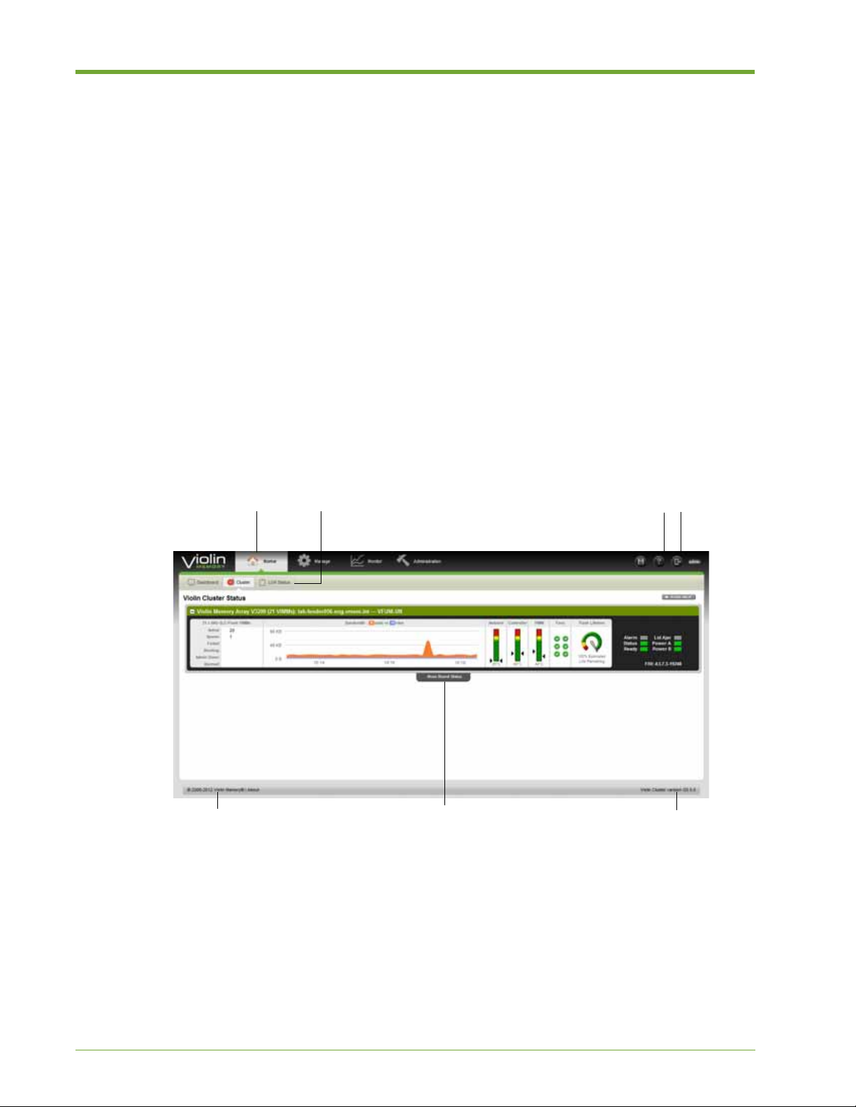
The streamlined HP VMA W eb Interface includes the following interactive components, as shown
in Figure 2.1:
• Main Menu Bar—Displays clickable icons for the major functional categories: Home,
Manage, Monitor, and Administration.
• Function Menu Bar—Changes to display the options for the currently active category . Click an
icon to display the associated page and submenu options.
• Online Help—Brings up context-sensitive help for the currently active page.
• Session—Shows the user name of the current user at the right, and exits the session when
clicked.
• Copyright—Displays the current copyright information.
• Board Status Tab—Expands to show board status information when clicked. Click the tab
again to hide the board status page.
• Software Version—Displays the version of the software currently running on the SAN
Gateway.
Figure 2.1 HP VMA Web Interface Overview
24 HP VMA SAN Gateway User’s Guide AM456-9026A
Page 25

System and Browser Requirements
This section provides information on the HP VMA Web Interface requirements for browsers,
display resolution, Adobe Flash Player, JavaScript, and cookies.
Supported Web Browsers
The following table lists the supported browsers and versions for the HP VMA Web Interface.
Operating System Supported Browsers
Linux Mozilla Firefox 4 and above
Google Chrome 11 and above
Windows Windows Internet Explorer 9 and above
Mozilla Firefox 4 and above
Google Chrome 11 and above
Table 2.1 Supported Web Browsers
Note: For Windows Internet Explorer, Compatibility Mode should be turned OFF.
The following table lists the recommended software and settings for optimum performance of the
HP VMA Web Interface.
Recommendation Description
Display resolution The minimum recommended display resolution for the HP
VMA Web Interface is 1024 by 768 pixels.
JavaScript JavaScript must be enabled for the HP VMA Web
Interface.
Adobe Flash Player Adobe Flash Player version 8 (or above) is required for
viewing charts in the HP VMA Web Interface.
Cookies Enable cookies for login and session management. Cookies
are also used to store dashboard page settings.
Table 2.2 Recommended for the HP VMA Web Interface
AM456-9026A HP VMA SAN Gateway User’s Guide 25
Page 26

Abbreviations for Large Numbers
The following abbreviations are used for large numbers throughout the HP VMA Web Interface:
Abbreviation Meaning
Bbytes
KB kilobytes
MB megabytes
GB gigabytes
TB terabytes
PB petabytes
Ta ble 2.3 Lar ge Number Abbreviations
For E (exabytes), Z (zettabytes), and Y (yottabytes), a single letter omitting the “B” is used for units
other than bytes, or to save space in a display.
Web Interface Help
There is Context-sensitive online help for any page in the W eb Interface—Click the Page Help icon
in the upper right corner of the Web Interface window.
For more information on available Help, see Information on page 89.
Logging In and Out of the Web Interface
This section demonstrates how to access the HP VMA Web Interface and then log in to the SAN
Gateway. The role assigned to your user account specifies the privileges you have and the tasks you
can perform after you log in. The pages that are available to you depend on your user role.
Role Description
Admin The Admin user can access the Web Interface pages for
Monitor Users with monitor privileges can only access pages for
Table 2.4 User Roles
managing, monitoring, and administrating. The only tasks
an Admin user cannot perform are those that are assigned
to the Crypto user.
monitoring overall status and media status.
26 HP VMA SAN Gateway User’s Guide AM456-9026A
Page 27

Logging In to the Web Interface
You access the HP VMA Web Interface through a Web browser. For more information, see
Supported Web Browsers on page 25.
To access the HP VMA Web Interface and log in, do the following:
1. Open a Web browser, as described in Supported Web Browsers on page 25.
2. In the browser URL field, enter one of the following:
http://<master_gateway_ip_address>
•
• http://<master_gateway_hostname>
• http://<cluster_node_ip_address>
• http://<cluster_node_hostname>
Note: If you specify the IP address or hostname of a gateway node of a redundant pair (other
than the master), the connection is automatically redirected to the Master Gateway. For a
redundant pair, it is recommended to use the management VIP address or name.
The Web Interface log in page appears.
3. Enter a valid username and password in the text fields of the Login page, as shown in the
following example.
4. Click Login. The Dashboard page appears.
5. Continue with Customizing the Dashboard on page 32.
AM456-9026A HP VMA SAN Gateway User’s Guide 27
Page 28
Logging Out of the Web Interface
You can log out of the SAN Gateway from any page in the HP VMA Web Interface.
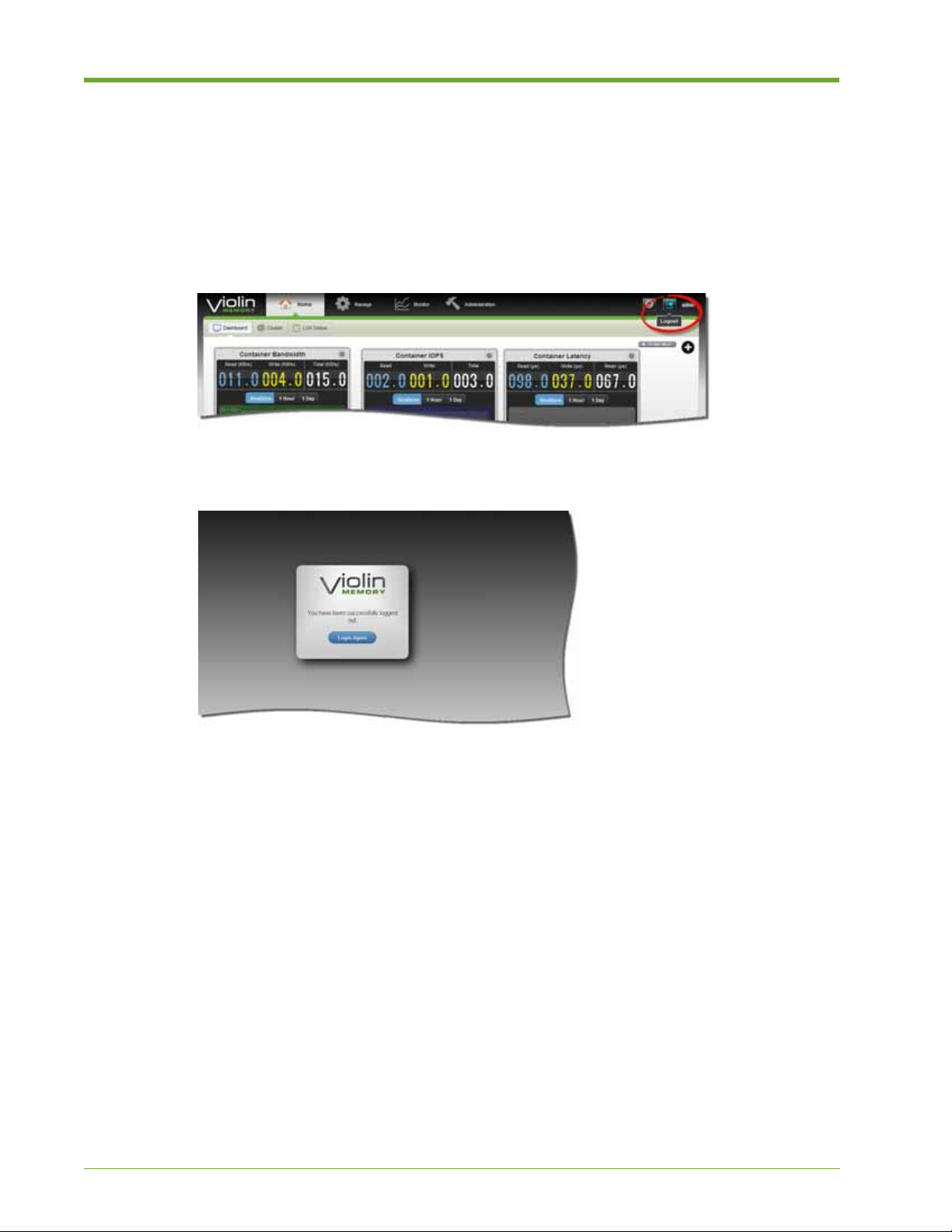
To log out of your Web Interface session, do the following:
1. From any page in the Web Interface, go to the upper right hand corner.
2. Click the session icon, as shown in the following example.
The Logout page appears acknowledging that you successfully logged out.
3. To log back in, click Login Again and re-enter your credentials.
28 HP VMA SAN Gateway User’s Guide AM456-9026A
Page 29

Web Interface Task Map
The following table provides an overview of the functional pages available within each category,
and the tasks you can perform from each page:
Main Menu Function Tasks
Home
Manage
Dashboard • Customizing the Dashboard on page 32
• Customizing Gadgets on page 34
Cluster • Viewing Cluster Status on page 36
• Viewing VIMM Status on page 37
• Viewing VIMMs by RAID Group or Category
on page 37
LUN Status • Viewing Container Status on page 39
• Viewing LUN Status on page 39
Manage LUNs • Searching, Sorting, and Performing LUN
Operations on page 42
• Creating and Deleting LUNs on page 43
• Editing LUNs on page 46
• Exporting LUNs, Initiator Groups, and
Initiators on page 48
Manage Initiators • Creating and Deleting Initiator Groups on
page 50
• Adding or Deleting Initiators from a Group on
page 52
Manage Targets • Viewing Target Status on page 54
• Managing Transport Protocols on page 54
Monitor
Overview • Customizing the Output Display on page 55
• Monitoring Container, LUN, and Port Data on
page 57
Monitor LUNs • Searching for a LUN on page 59
• Analyzing Data for a LUN on page 60
Monitor Targets • Selecting a Target Port on page 61
• Analyzing Data for a Target on page 62
Table 2.5 Web Interface Task Map
AM456-9026A HP VMA SAN Gateway User’s Guide 29
Page 30

Main Menu Function Tasks
Administration
Cluster Admin • Viewing Software Version and Boot Images
on page 64
• Rebooting or Shutting Down a Node on page
64
• Changing and Saving Configuration Files on
page 65
• Viewing Gateway Node Details on page 66
• Viewing Alerts on page 66
• Searching for and Viewing Logs on page 67
• Viewing Node Versions on page 68
Network • Viewing Current Network Settings on page 69
• Changing the Gateway Management Virtual
IP Address on page 70
• Modifying Global Default Gateway Settings
on page 70
• V iewing and Modifying DNS Settings on page
70
• V iewing and Modifying NTP Settings on page
72
Notification • Specifying Call Home Settings on page 76
Tools • Adding and Removing Feature Licenses on
Information • Accessing Context-Sensitive Help on page 90
Table 2.5 Web Interface Task Map
• Viewing and Modifying Web Admin Settings
on page 73
• Viewing Gateway Node Details on page 66
• Managing User Accounts on page 76
• Managing E-mail Settings on page 79
• Managing E-mail Notifications on page 83
• Managing SNMP Settings on page 84
• Managing SNMP Traps on page 87
page 88
• Viewing System, License, and Copyright
Information on page 90
• Viewing System, License, and Copyright
Information on page 90
30 HP VMA SAN Gateway User’s Guide AM456-9026A
Page 31

Home Dashboard
The Home dashboard is a landing page that provides a selection of metrics that track system health
and performance. The customizable dashboard allows you to easily add, change, and rearrange the
gadgets for at-a-glance system assessment. Likewise, the Cluster Status page provides a visual
overview of cluster health and performance. The LUN Status page provides an easy access list of
all LUNs and their statistics.
Note: The dashboard supports Internet Explorer 9 (IE 9) and higher. If you are using an earlier
version of Internet Explorer, the dashboard does not display. For more information, see Supported
Web Browsers on page 25.
You can perform the following tasks from the Home function pages:
Dashboard • Customizing the Dashboard on page 32
Function Tasks
• Customizing Gadgets on page 34
• Viewing Cluster Status on page 36
• Viewing VIMM Status on page 37
• Viewing VIMMs by RAID Group or Category on page 37
• Viewing LUN Status on page 39
Cluster • The Cluster Status page provides the following information: on
page 36
• Viewing VIMM Status on page 37
• Viewing VIMMs by RAID Group or Category on page 37
LUN Status • Viewing Container Status on page 39
• Viewing LUN Status on page 39
Dashboard
Y ou ca n select the gadgets that appear o n the landing page and arrang e them to maximize ef ficiency
for your style of work. You can populate your dashboard with any of the following gadgets.
• Bandwidth—Shows reads and writes performed in Kilobytes per second (KB/s). You can
display this information at the container level or LUN level. Click the settings icon in the
upper right corner to customize the display.
• IOPS—Shows read, write, and total statistics in real-time, per hour, or per day values. Click
the settings icon in the upper right corner to customize the display. You can display this
information at the container level or LUN level.
• Latency—Shows read, write, and total latency for a container or LUN in real-time, per hour, or
per day values. Click the settings icon in the upper right corner to customize the display.
AM456-9026A HP VMA SAN Gateway User’s Guide 31
Page 32

• Live Stats—Shows real-time values for bandwidth, IOPS and latency on a LUN level or
container level. Click the settings icon in the upper right corner to customize the display.
• Indicators—Shows the LED, temperature and fan status for a container on an array. Click the
settings icon in the upper right corner to customize the display.
• Flash/VIMM Status—Shows the VIMM status (number active, down, etc.) and the remaining
length of flash life for a container on an array. Click the settings icon in the upper right corner
to customize the display.
• Container Status—Shows the amount of space used and available on the container, the number
of LUNs, and provides an HA status indicator for a container on an array. Click the settings
icon in the upper right corner to customize the display.
• Port Stats—Shows the Received and Sent statistics for Fibre Channel ports in real-time, per
hour, or per day values for a port within a container. Click the settings icon in the upper right
corner to customize the display.
Note: For instructions on how to change the information shown on a gadget, see Customizing
Gadgets on page 34.
Customizing the Dashboard
You can customize the dashboard by adding, removing, and rearran gin g the placement of the
gadgets for optimum efficiency.
To customize the dashboard and view data, do the following:
1. Log in to the SAN Gateway, as described in Logging In and Out of the Web Interface on page
26. The default dashboard appears.
2. Click the plus icon (+) in the lower right corner allows to access the toolbar.
Note: If you are not able to view the dashboard, you may need to upgrade your browser. For
more information, see
Supported Web Browsers on page 25.
32 HP VMA SAN Gateway User’s Guide AM456-9026A
Page 33
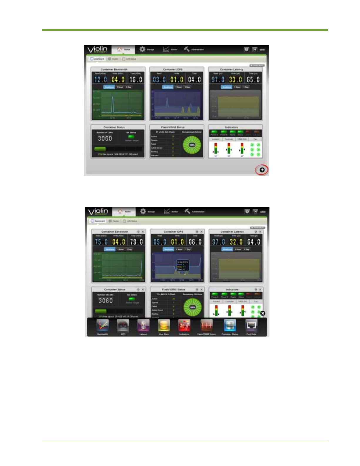
The toolbar appears at the bottom of the window, as shown in the following example.
3. Click an icon on the toolbar to add it to the dashboard, then select and drag icons to rearrange.
Click the X icon in the upper right corner of the gadget to remove it from the dashboard
display.
AM456-9026A HP VMA SAN Gateway User’s Guide 33
Page 34
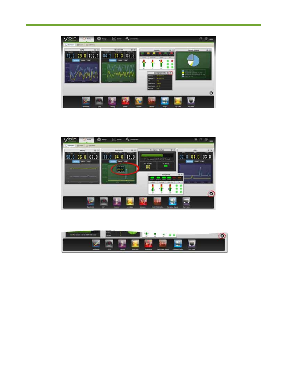
4. To display detailed data for a gadget, move your cursor over an area in the graph. A pop-up
window appears, as shown in the following example.
5. To hide the toolbar, click the X icon in the lower right corner of the window.
Customizing Gadgets
Each dashboard gadgets allows you to customize the display.
To customize the information shown on a gadget, do the following:
1. Open the gadget on the dashboard, as described in Customizing the Dashboard on page 32.
2. Click the Settings icon in the upper right corner of the gadget, as shown circled in red in the
following example.
34 HP VMA SAN Gateway User’s Guide AM456-9026A
Page 35
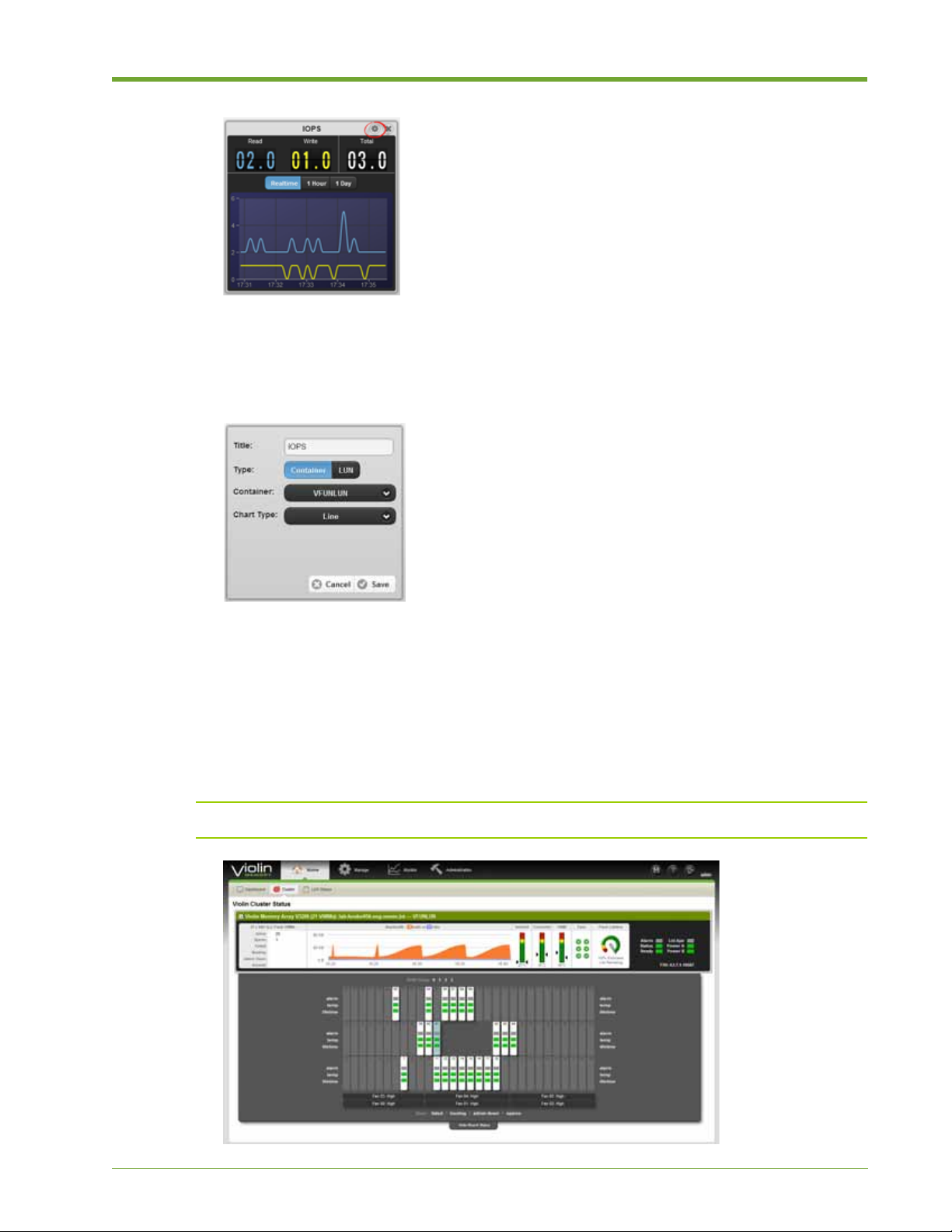
The gadget flips over to show a back panel with options appropriate for that gadget.
3. Make the desired selections and click Save to apply, or Cancel to revert to the previous
settings. The gadget flips back to the front panel display.
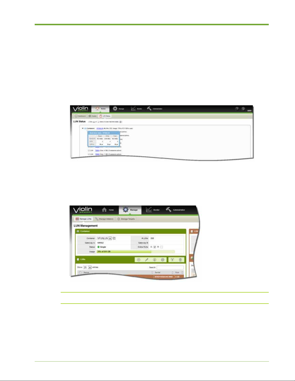
Cluster
The Cluster Status page displays information depi cting the health and performance of the gateway
nodes in the management group. Easy to read graphics allow you to easily tell f there is a problem
with the system. An expandable Board Status page provides an at-a-glance view of VIMM
statistics.
Note: A status message appears in the header when a RAID rebuild is in progress
AM456-9026A HP VMA SAN Gateway User’s Guide 35
Page 36

The Cluster Status page provides the following information:
• Master SAN Gateway Statistics
— DRAM and flash allocation
—Port ID
— T otal flash memory
— Performance data: read and write rates, DMA active, and pending
— Activity graph (reads and writes) for this SAN Gateway
— Network data: rates of client and server activity
— System drive read and write rates
— Additional SAN Gateway statistics: same data as for master
• Memory Array Statistics
— Number of VIMMs in each state (active, spare, booting, etc.)
— Activity graph (reads and writes) color-coded for each SAN Gateway
— Temperatures of ambient air, controller, and VIMMs (for each SAN Gateway)
— Fan status indicators
— Estimated lifetime of flash drives
— Status lights: Alarm, Status, and Ready
• Network Stats
— Client- and server-side statistics.
— Measure the throughput of all operations including hits, misses, and write-throughs.
Viewing Cluster Status
The HP VMA Cluster Status page is easily accessible from the Function toolbar.
To view cluster statistics, do the following:
1. Select Home > Cluster. The HP VMA Cluster Status page appears.
2. Check alarm status at the right side of the panel.
3. Verify the life span of the flash in the Flash Lifetime panel.
4. Check the health of the Fans. A failed fan displays as red. A problematic fan displays as
yellow. A green box with a white check mark represents a healthy, fully functioning fan.
36 HP VMA SAN Gateway User’s Guide AM456-9026A
Page 37

5. Check the VIMM, Controller, and ambient temperatures. Green is healthy, yellow a caution,
and red a warning.
6. View a high-level synopsis of the flash VIMM statistics in the far left panel.
Viewing VIMM Status
The HP VMA Cluster Status page can be expanded to view board-level information about a
connected VMA Memory Array. The Board Status page shows a color -coded array of VIMMs with
indicator boxes for alarm status, temperature, and remaining lifetime.You can move your cursor
over a VIMM to view a detailed status.
To view VIMM statistics, do the following:
1. Select Home > Cluster, to display the HP VMA Cluster Status page.
2. Click the Show Board Status tab.
3. For general status information about specific VIMMs, move the cursor over the VIMM
number.
4. T o view Alarm, Temp, or Lifetime information, move the cursor over the appropriate indicator
box.
Viewing VIMMs by RAID Group or Category
You can selectively display RAID group information on the Board Status page, as well as category
details.
To view RAID group and category board-level information, do the following:
1. Select Home > Cluster, to display the HP VMA Cluster Status page.
2. Click the Show Board Status tab.
3. To view VIMMs by RAID group, select a RAID Group number at the top-center of the Board
Status panel.
AM456-9026A HP VMA SAN Gateway User’s Guide 37
Page 38

Selecting a RAID Group highlights the VIMMs belonging to that RAID Group in the Board
Status panel, as shown in the following example.
4. To view failed VIMMs , select the Failed link in the Show area of the Board Status panel.
A failed VIMM appears orange, as shown in the following example.
5. To view booting VIMMs, select the Booting link in the Show area of the Board Status panel.
6. To view admin down VIMMs, selec t the Admin Down link in the Show area of the Board
Status panel.
7. To view spare VIMMs, selec t the Spares link in the Show area of the Board Status panel.
LUN Status
The LUN Status page allows you to view information about containers and the LUNs within those
containers. Every LUN is created within a storage container (array).
38 HP VMA SAN Gateway User’s Guide AM456-9026A
Page 39
Viewing Container Status
The LUN Status page provides easy access to information about the container in an array. At-aglance information includes the container name, its address, and the number of LUNs within the
container. The following task demonstrates how to view more detailed information.
To view LUN and container status, do the following:
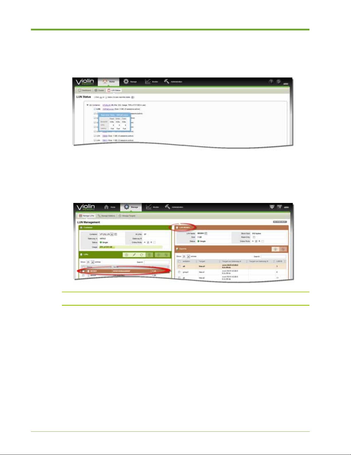
1. Select Home > LUN Status. The LUN Status page appears.
2. Select the Container icon to view real-time statistics about the container.
3. Select the LUN icon to view real-time statistics about the LUN.
4. Click the container name to view detailed information about the container and the LUNs it
contains. The LUN Management page appears, with the container information in the upper left
panel.
Note: For more information on managing LUNs, see "Manage LUNs" o n page 41.
Viewing LUN Status
The LUN Status page provides easy access to information about the container in an array. At-aglance information includes the LUN name, size, and the number of active sessions. The following
task demonstrates how to view more detailed information.
AM456-9026A HP VMA SAN Gateway User’s Guide 39
Page 40
To view LUN and container status, do the following:
1. Select Home > LUN Status. The LUN Status page appears.
2. Select a LUN icon to view real-time statistics about the container.
3. Select the LUN icon next to the name to view real-time statistics about that LUN.
4. Click a LUN name to view detailed information about that LUN. The LUN Management page
appears, with the selected LUN highlighted in the LUN panel on the left. In the top right panel,
details of the selected LUN are shown.
Note: For more information on managing LUNs, see "Manage LUNs" on page 41.
40 HP VMA SAN Gateway User’s Guide AM456-9026A
Page 41

Manage
The Manage function provides easy access to the tools you need to manage LUNs, LUN groups,
initiators, and targets. You can perform the following tasks from the Manage function pages:
Function Tasks
Manage LUNs • Searching, Sorting, and Performing LUN Operations on page 42
• Creating and Deleting LUNs on page 43
• Editing LUNs on page 46
• Exporting LUNs, Initiator Groups, and Initiators on page 48
Manage Initiators • Creating and Deleting Initiator Groups on page 50
• Adding or Deleting Initiators from a Group on page 52
Manage Targets • Viewing Target Status on page 54
• Managing Transport Protocols on page 54
Manage LUNs
The following panels comprise the LUN Management Page:
• Container—Displays information about the container including the name, the percentage of
space used, and the number of LUNs. The Containers drop-down list enables you to choose
another container (on a different array).
You can view the online status of A port and port B (Gateway A and Gateway B), and take the
A Port or B Port offline by clicking the appropriate check box. However, taking a port offline
is generally not recommended.
• LUNs—Shows information about the LUNs within the selected container, includin g name and
size. Y ou can create LUNs, search for a LUN, reorder the list of LUNs, and perform actions on
LUNs by selecting one or more check boxes. When you highlight a LUN (selecting it so that it
changes color), detailed information about the LUN appears in a panel on the upper right.
Note: Only one LUN can be highlighted at a time.
• Highlighted LUN—Shows detailed information on the highlighted LUN (in the LUNs panel),
including if it is read-only, and/or has Port A or Port B offline. You can view and add or
remove Exports for a selected LUN.
Caution: You can change the online status of Port A and Port B (Gateway A and Gateway B) in the highlighted
LUN information panel. However, this is generally not recommended.
AM456-9026A HP VMA SAN Gateway User’s Guide 41
Page 42

Searching, Sorting, and Performing LUN Operations
A search (filter) operation is performed across all columns simultaneously to return the desired
results. Sorting applies to the selected column. However, the sorting changes the order of all the
records (rows/columns).
Note: You can select multiple LUNs and perform an operation on them simultaneously. A check
mark in the box next to the LUN name shows that a LUN is selected.
To search for a LUN and customize the display, do the following:
1. Select Manage > Manage LUNs. The LUN Management page appears.
2. To se arch for a LUN, enter a string in the Search field. A list of LUNs that contain the string
appear in the LUNs panel.
3. Select a LUN to highlight it and view details in the upper right.
4. Click the down arrow in the header to view the LUN list in descending order. Click the up
arrow to view the list in ascending order (the default display).
42 HP VMA SAN Gateway User’s Guide AM456-9026A
Page 43
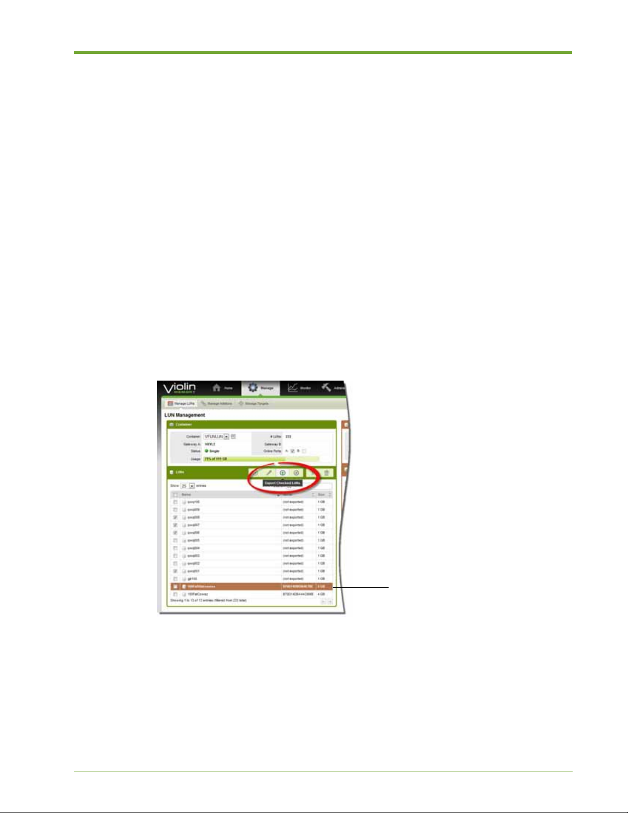
5. To change the number of entries shown, choose one of the following from the Show entries
The highlighted LUN does not have a
check mark (not selected), and therefore
is not included in the operation. You
must select a LUN to include it in an
operation.
drop-down list: 10, 25, 50, or 100. The default is 25.
To perform operations on one or more LUNs, do the following:
1. Select Manage > Manage LUNs. The LUN Management page appears.
2. In the LUNs panel, select the check boxes next to the desired LUNs. A check mark appears in
the box next to the name.
Note: A highlighted LUN that is not selected is not included in an operation. Performing an
operation on multiple LUNs simultaneously may take some time.
3. Select one of the following options to apply the operation to all of the selected LUNs:
Remove Checked LUN(s)
•
• Remove Exports for Checked LUN(s)
• Export Checked LUN(s)
In the following example, Export Checked LUNs is selected. For more information on how to
export LUNs, see Exporting LUNs, Initiator Groups, and Initiators on page 48.
Creating and Deleting LUNs
This section walks you through the process of creating a LUN. Every LUN is created within a
container. The size and amount of used space in the container may restrict the number and size of
the LUNs created within the container.
AM456-9026A HP VMA SAN Gateway User’s Guide 43
Page 44

Prerequisites
Verify the block size that is acceptable for the clients (initiators) on your network.
Disk storage systems previously assumed a 512-byte sector or block size as the unit to store data.
Newer devices, such as HP VMA Memory Arrays, have a native storage unit sized at 4096 bytes
but can also emulate 512 bytes. Not all client operating systems are able to understand accessing
anything other than a 512-byte based disk drive.
T o be safe, choose a 512 block size if you are not sure what type of clients will be connected to an
exported LUN. For example, RHEL5 and Windows Server 2003 are not be able to properly use a
4096 block-sized disk, and this selection leads to unexpected behavior. For newer op erating systems
which support a 4096 block size, the emulation layer can be avoided to provide optimal
performance.
To create a LUN, do the following:
1. Select Manage > Manage LUNs. The LUN Management page appears.
2. In the Container panel, select a container from the Container drop-down list. This is the
container in which the new LUN will reside.
3. In the LUNs panel, click the Create New LUNs icon.
The Create LUN window appears.
4. Specify the following:
The number of LUNs in the # LUNs to Make field.
•
• The name of the LUNs in the LUN Name field.
Note: When creating more than one LUN, the name of each new LUN is appended with a number
beginning with 1, and continuing through the number of specified LUNs. This ensures that each
LUN has a unique name. Creating a large number of LUNs at once (50 LUNs or more), the
operation may take some time.
44 HP VMA SAN Gateway User’s Guide AM456-9026A
Page 45

5. Define the size of a LUN, in one of the following ways:
To define the size of the LUN based on the space available, select Use all available space
•
equally
.
• T o manually define the size of each LUN, select Specific size per LUN and enter the size in GB.
Note: The size of the LUNs may be restricted by the space available in the container.
6. Select one of the following block sizes for the LUN:
• 512 bytes
.
• 4096 bytes.
Caution: Not all systems can handle 4096-byte blocks. Us e 512-byte blocks, if you are not sure what
type of clients will be connected to an exported LUN.
7. Make the following selections, as appropriate:
• Zero-out drive space when creating
LUNs. Zeroing-out data may take some time for large LUNs.
—Securely erases the drive prior to creating the new
• Online—Sets the LUNs online.
• Read-only—Sets the LUNs as read-only.
8. Click OK. The specified LUNs are created in the container.
To delete a LUN, do the following:
1. Select Manage > Manage LUNs. The LUN Management page appears.
2. In the Container panel, select a container from the Container drop-down list.
3. Search for the LUN, as described in Searching, Sorting, and Performing LUN Operations on
page 42.
AM456-9026A HP VMA SAN Gateway User’s Guide 45
Page 46

4. Select the LUN so that it highlights, then remove the LUN exports in the following way:
a. In the Exports panel on the right, click the check boxes for each of the exports associated with the
LUN.
b. Click th e Delete icon. Then click OK in the pop-up dialog that appears to confirm the action.
Note: All exports must be removed before the LUN can be deleted.
5. Click the check box of the LUN you want to delete, if you haven’t already done so. A check
mark appears.
Note: The check box must display a check mark for the LUN to be deleted.
6. In the LUNs panel, click the Delete icon. Then click OK in the pop-up dialog that appears to
confirm the action.
Editing LUNs
You can change the name of an existing LUN and increase the size of the logical volume.
Decreasing the size of an existing LUN is not supported.
For a smaller size LUN, create a new LUN of the desired size. For more information, see Creating
and Deleting LUNs on page 43.
WARNING! Existing file systems on the client side are not extended as part of the resize operation. File
systems must be extended from the client initiator . Not all client systems will detect the LUN size change until
they reboot.
To modify access to an existing LUN, do the following:
1. Select Manage > Manage LUNs. The LUN Management page appears.
2. In the Container panel, select a container from the Container drop-down list.
3. Select the LUN so that it highlights. Details appear in the top-right LUN information panel.
46 HP VMA SAN Gateway User’s Guide AM456-9026A
Page 47

4. In the LUN information panel make the following selections, as necessary:
— Block Size—Shows the block size of the highlighted LUN.
— Read Only—Activating read-only access on an existing LUN can cause data loss for connected
clients with cached data.
— Online Ports—Unchecking these options takes the LUN offline for the respective SAN Gateway
nodes.
To change the name of an existing LUN, do the following:
1. Select Manage > Manage LUNs. The LUN Management page appears.
2. In the Container panel, select a container from the Container drop-down list.
3. Select the LUN so that it highlights, then click the Edit LUN icon.
4. In the Edit LUN dialog, click Rename LUN.
5. Enter the new name in the New LUN Name text box, and click OK.
AM456-9026A HP VMA SAN Gateway User’s Guide 47
Page 48
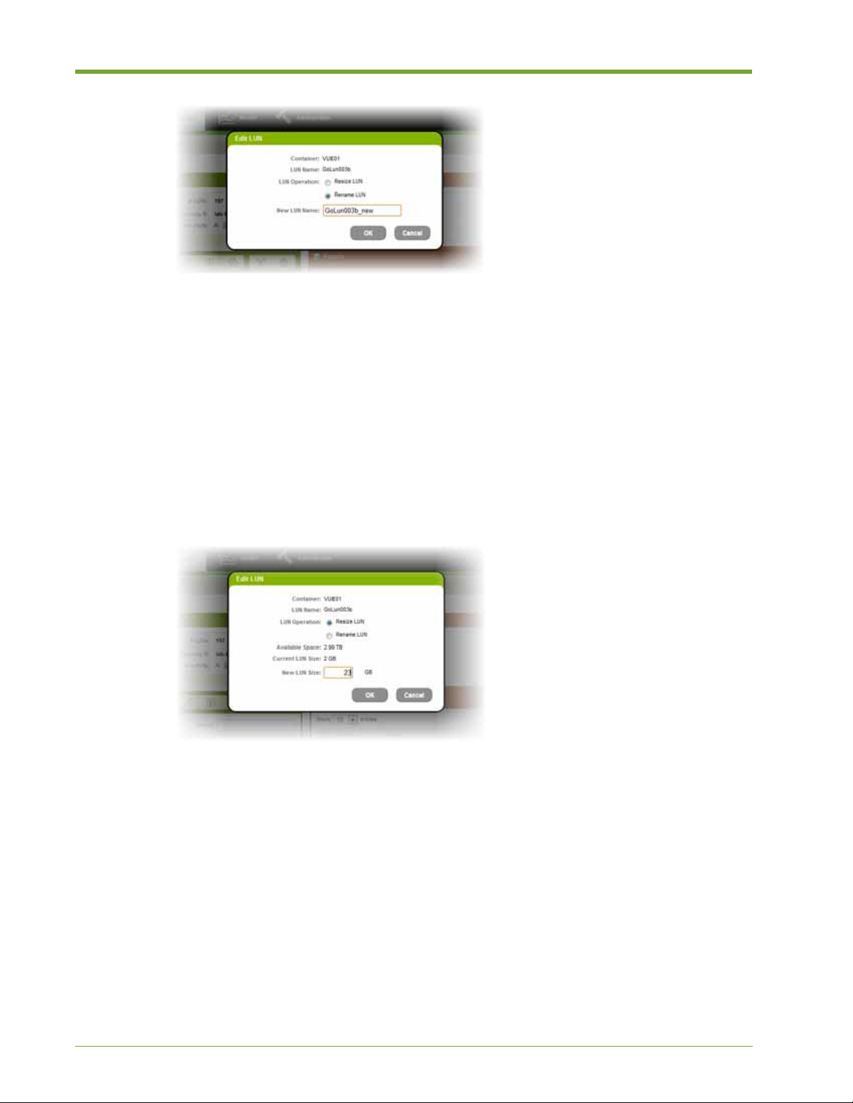
The new name is applied and appears in the LUNs panel.
To increase the size of an existing LUN, do the following:
1. Select Manage > Manage LUNs. The LUN Management page appears.
2. In the Container panel, select a container from the Container drop-down list. This is the
container in which the LUN resides.
3. Select the LUN so that it highlights, then click the Edit LUN icon.
4. In the Edit LUN dialog, click Resize LUN.
5. Enter the New LUN size (GB) in the text box, and then click OK.
The LUN size is increased and appears in the LUNs panel.
Exporting LUNs, Initiator Groups, and Initiators
This section shows you how to export LUNs, initiator groups, and initiators.
To export LUNs, do the following:
1. Select Manage > Manage LUNs. The LUN Management page appears.
2. In the Container panel, select a container from the Container drop-down list.
3. In the LUNs panel, select the check box next to the LUN(s) you want to export.
Note: The check box next to the LUN name must show a check mark for the LUN to be included
48 HP VMA SAN Gateway User’s Guide AM456-9026A
Page 49

in the export.
4. Click Export Checked LUNs. The Add Export dialog box appears.
5. Do one of the following to select the initiators to which the LUNs will be exported.
T o export to all initiators, select the All Initiators option button.
•
• To export to select initiator groups or initiators, select Specific Initiator Groups and/or
Initiators
(each on their own line) in the Individual Initiator panel.
. Select one or more Initiator Groups from the list, and enter and select initiator names
6. Specify the target ports through which the LUNs are exported in one of the following ways:
Select All Ports, to export through all target ports.
•
• Select Specific Ports, to export through target ports selected from the list.
7. Assign IDs to the exported LUNs in one of the following ways:
Select Value and enter a value in the text field to manually assign a LUN ID.
•
User-defined LUN IDs can make it easier to differentiate between LUNs. If you do assign a userdefined LUN ID, HP VMA Memory recommends that you specify a number below 255 as some
AM456-9026A HP VMA SAN Gateway User’s Guide 49
Page 50
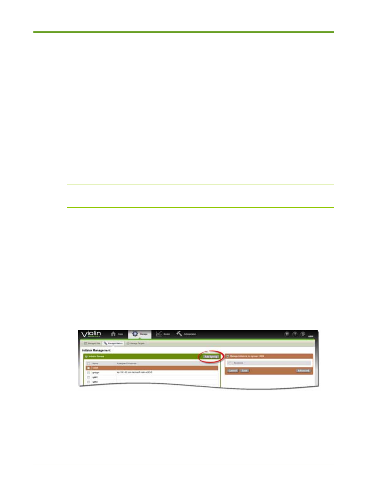
operating systems (for example, Windows) only discover LUN IDs between 0 and 254. This section
is automatically disabled when you create multiple LUNs at one time.
• Select Auto to automatically assign an ID to the exported LUNs. This option is mandatory when
you export multiple LUNs at once.
8. Click OK. Initiator and target information for the exported LUNs appears in the Exports panel
on the right side of the window.
Manage Initiators
In a HP VMA Memory environment, the hosts (such as database servers or application servers) that
access LUNs are called
access to LUNs on an initiator-by-initiator basis, as well as by defining initiator groups (igroups).
Using the Web Interface, you can easily create initiator groups and assign a group to a host.
Note: Check with your network administrator before adding initiator hosts in the Advanced panel to
verify the correct addresses for the hosts.
initiators and the SAN Gateways are referred to as targets. You can control
Creating and Deleting Initiator Groups
You can create and delete Initiator groups from the Manage > Manage Initiators page of the Web
Interface. A list of initiator groups is shown in the left panel, with a list of available sessions shown
in the right panel for the highlighted initiator group. You can define sessions that may not yet be
connected to the network using the Advanced pane l
To create an initiator group, do the following:
1. Select Manage > Manage Initiators. The Initiator Management page appears.
2. Click Add igroup.
The New Initiator Group dialog appears.
3. Enter a name in the New Initiator Group dialog and click OK. The new group appears in the
Initiator Group table.
50 HP VMA SAN Gateway User’s Guide AM456-9026A
Page 51

To delete an initiator group, complete the following steps:
1. Select Manage > Manage Initiators.
2. Select one or more initiator groups from the Initiator Groups list.
A check mark appears next to the name of a selected igroup. Only igroups with a check mark
next to the name will be deleted.
3. Click Remove Checked groups.
A dialog appears prompting you to confirm the action.
4. Click OK.
A prompt appears verifying the success of the operation, and the selected initiator groups are
removed from the list.
AM456-9026A HP VMA SAN Gateway User’s Guide 51
Page 52

Adding or Deleting Initiators from a Group
You can select initiator hosts to add to an existing initiator group from the panel on the right. Or
from the Advanced panel, you can add initiator types that do not appear in the list, or that may not
yet be on the network.
This section demonstrates how to add initiator hosts to an igroup by selecting them from the list,
and then add initiators using the Advanced panel.
Caution: Adding an initiator to multiple igroups can create conflicts, and cause problems in export behavior.
Prerequisites
When adding initiators, verify the validity and availability of the address. Check with your system
administrator regarding the availability status of the initiators.
Each initiator address has a protocol-specific identifier:
• Fibre Channel initiator identifier format: wwn
Fibre Channel initiators are fixed by the appropriate HBA port, for example
wwn.01:02:03:04:05:06:07:08
To add or remove initiators from an existing igroup, do the following:
1. Select Manage > Manage Initiators.
2. Select an initiator group from the Initiator Groups list on the left. The group is highlighted in
the Initiator Groups list. In the Sessions panel on the right, the initiators assigned to the group
appear with check marks next to the addresses.
.
3. To add initiator hosts to the group, select any empty check box.
4. To remove an initiator host from the group, deselect a check box.
5. To add initiator hosts that do not appear in the list, in the Manage Initiators panel click
Advanced.
6. Enter a valid initiator host address in the text field. Press Enter to add another addres s.
52 HP VMA SAN Gateway User’s Guide AM456-9026A
Page 53

Note: Each address must be on its own line.
7. Click Save. The newly added initiators appear in the Manage Initiators pan el and are
associated with the selected (highlighted) initiator group.
Note: Initiator hosts added in the Advanced panel appear in the group even if the host has not yet
been added to the network. Check with your network administrator for status on the availabili ty of
these hosts.
Manage Targets
In a cluster, each SAN Gateway operates as a SAN (Fibre Channel) target that provides access to
the LUNs stored on its attached memory arrays. Fibre Channel target ports are supported. Every
target is a specific port on a hardware Fibre Channel host bus adapter (HBA).
AM456-9026A HP VMA SAN Gateway User’s Guide 53
Page 54

Viewing Target Status
On the T arget Management page, the details for the highlighted port appear in the panel on the right.
The node, target name, hostname, speed, and address of each type of target port.
To view status information for a target, do the following:
1. Select Manage > Manage Targets. The Target Management page appears, showing
information for all available target ports in one table.
2. To view details on a specific target, select (highlight) the target in the Available Targets panel
on the left.
Managing Transport Protocols
Some target port types are configured automatically when a storage container is created. Other
target ports must be configured manually.
• Fibre Channel target ports are automatically configured when you create the storage containers
on HP VMA Memory Arrays.
To enable target ports, do the following:
1. Select Manage > Manage Targets. The Target Management page appears.
2. Click the appropriate Enable protocol button.
To a disable active target ports, do the following:
1. Select Manage > Manage Targets. The Target Management page appears.
2. In the Manage Target Protocols panel, click the appropriate Disable protocol button.
54 HP VMA SAN Gateway User’s Guide AM456-9026A
Page 55

Monitor
The Monitor function provides an at-a-glance view of the health and performance of cluster nodes,
and the ability to analyze historical data and real time trends. LUN monitoring provides container
level statistics both on a per-node basis, as well as aggregated. T arget mo nitoring provides port level
statistics. You can perform the following tasks from the Monitor function pages:
Function Tasks
Overview • Customizing the Output Display on page 55
• Monitoring Container, LUN, and Port Data on page 57
Monitor LUNs • Searching for a LUN on page 59
• Analyzing Data for a LUN on page 60
Monitor Targets • Selecting a Target Port on page 61
• Analyzing Data for a Target on page 62
Overview
The Overview function provides a high-level view of real-time or historical data. You can
customize how you view the data, choosing between line and area graphs, time trends, as well as
the type of metrics used to formulate the data. You also have the option to view data for a container,
LUN, or port.
• Real Time Performance Trend—Shows the last five minutes of performance trends for the
selected metric. New real time values are appended into the graph every ten seconds.
• Current Value—Shows real time data at this time. The graph time is listed at the bottom of the
panel.
Customizing the Output Display
The following task demonstrates how to customize the data display to suite your needs. You can
specify the visual graph you prefer, the time trend, and the applied metrics.
AM456-9026A HP VMA SAN Gateway User’s Guide 55
Page 56

Y ou can also choose to view the aggregate data (A+B) from both SAN Gateway nodes, or view data
for the nodes separately (A, B). If you select the A only or B only option, only the data for that
particular node is shown.
To customize the data output display, do the following:
1. Select Monitor > Overview. The Monitoring page appears.
2. Click Settings & Download. The panel expands to show the following options.
3. Select a Container name from the drop-down list to display its data.
4. Select the Type of information to display from the drop-down list.
General—Monitors data for all ports.
•
• LUN—Monitors data for a specific LUN.
• Fibre Channel—Monitors data for Fibre Channel ports.
For more information, see Monitoring Container, LUN, and Port Data on page 57.
5. Select a Metric display type from the drop-down list, as shown in the following example.
A+B shows aggregated data for both Gateway nodes.
•
• A, B shows data separately for both Gateway nodes.
• A only shows data for the Gateway master node. B only shows data from the standby node.
The results appear in the Current Value panel on the right.
6. Choose an option from the drop-down list to customize the graph display. The Real-Time
Performance Trend display changes accordingly.
56 HP VMA SAN Gateway User’s Guide AM456-9026A
Page 57

7. To specify the real-time performa nce trend, at the top of the left-most panel choose one of the
following options:
• Last 1 H:
Shows data averaged every one minute.
• Last 24 H: Shows data averaged over the last 24 hours.
8. To view detailed information for a point in time, move the cursor over a point on the graph. A
pop-up dialog appears, as shown in the following example.
9. Click Settings & Download again to hide the panel.
Monitoring Container, LUN, and Port Data
You can analyze data in different containers, LUNs, and across different ports. This section
demonstrates how to perform each of these tasks.
To monitor a specific container, do th e following:
1. Select Monitor > Overview. The Monitoring page appears.
2. Click Settings & Download to expand the panel.
3. Choose a container name from the Container drop-down list. The display changes to show the
real-time data for the selected container.
4. From the Type drop-down list, choose General (default setting).
5. (Optional) To save a snapshot of performance data, do the following:
AM456-9026A HP VMA SAN Gateway User’s Guide 57
Page 58
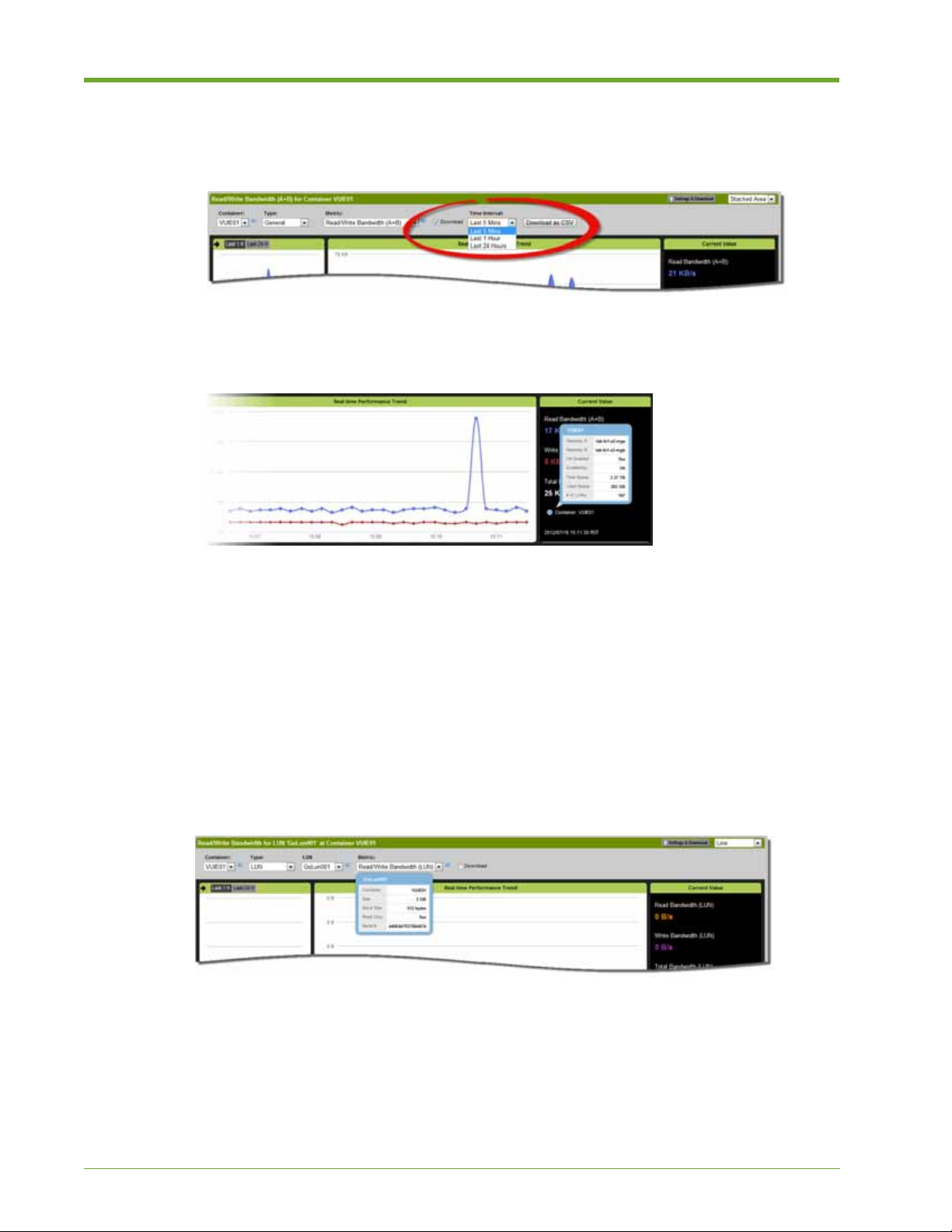
a. Click the Download check box.
b. Choose a Time Interval from the drop-down list.
c. Click Download as CSV. Data for the specified time interval is saved as a CSV file.
6. (Optional) V iew detai led information on the container by clicking the blue information (i) icon
in the Current Value panel or next to the Container drop-down list.
7. (Optional) Modify the output display, as described in Customizing the Output Display on page
55.
To monitor a specific LUN, do the following:
1. Select Monitor > Overview. The Monitoring page appears.
2. Click Settings & Download to expand the panel.
3. Choose a container name from the Container drop-down list. The display changes to show the
real-time data for the selected container.
4. From the Type drop-down list, choose LUN, then select a name from the LUN drop-down list
on the right.
5. (Optional) View detailed information on the LUN by clicking the blue information (i) icon.
6. Select a Metric from the drop-down list. Click the blue information (i) icon for a description of
each option.
The Current Value panel changes to display the data for the selected metric.
58 HP VMA SAN Gateway User’s Guide AM456-9026A
Page 59
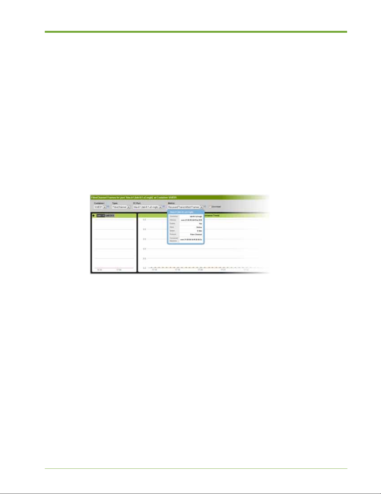
7. (Optional) Modify the output data display, as described in Customizing the Output Display on
page 55.
To monitor a port, do the following:
1. Select Monitor > Overview. The Monitoring page appears.
2. Click Settings & Download to expand the panel.
3. Choose a container name from the Container drop-down list. The display changes to show the
real-time data for the selected container.
4. Choose a port from the Type drop-down list, then choose a port name from the drop-down list
that appears to the right.
Note: The General option monitors data for all ports. A port drop-down list does not appear when
this option is selected.
5. (Optional) To view detailed information about the port, click the information (i) icon next to
the port name.
6. Choose a Metric from the drop-down list, as available. Some port selections only provide one
option.
7. (Optional) Modify the output data display, as described in Customizing the Output Display on
page 55.
Monitor LUNs
You can monitor the performance of selected LUNs in a specified container with Monitor LUNs
function. The LUN Monitoring page allows you to view real-time statistics or historical trends over
the last hour or twenty-four hours.
Searching for a LUN
Search is an important function, especially when hundreds of LUNs are involved.
AM456-9026A HP VMA SAN Gateway User’s Guide 59
Page 60

To search for a specific LUN, do the following:
1. Select Monitor > Monitor LUNs. The LUN Monitoring page appears.
2. Choose a container name from the Container drop-down list. The display changes to show the
LUNs in the selected container.
3. Enter a string in the search field and press Enter. LUN names that match the search string
appear in the list on the left.
4. Select the LUN so that it highlights.
Analyzing Data for a LUN
You can analyze the following performance data types for a selected LUN side-by-side in a single
window display:
• Read/Write Bandwidth
• Read/Write IOPs
• Read/Write Latency
To analyze the performance for a specific LUN, do the following:
1. Select Monitor > Monitor LUNs.
2. Select a Container from the drop-down list. A list of LUNs appears in the left panel.
3. To find a specific LUN, follow the instructions described in Searching for a LUN on page 59,
and then select the LUN so that it highlights.
4. Select one of the following time intervals for data analysis:
— Real Time Displays data as it happens, in real time
—
1 H Displays aggregated data for the last hour
—
24 H Displays aggregated data for the last 24 hours
60 HP VMA SAN Gateway User’s Guide AM456-9026A
Page 61

5. Choose a graph type from the drop-down list. The following example shows a Stacked Area
graph.
6. Move your mouse cursor over a point on a graph to display detailed information for that
specific point in time.
Monitor Targets
You can analyze performance data for target ports in time statistics, as well as using historical
trends.
Note: Fibre Channel data is shown in frames per second.
Selecting a Target Port
The target ports configured for your system are easily accessible from the Monitor Targets page.
To select a target port for monitoring, do the following:
1. Select Monitor > Monitor Targets. The Target Port Monitoring page appears. Statistics for
each target port are shown in the left panel, with real time data in a graph format on the right.
2. Select a port name from the list on the left so that it highlights. The graphs on the right side of
the window change to display data for the selected target.
AM456-9026A HP VMA SAN Gateway User’s Guide 61
Page 62
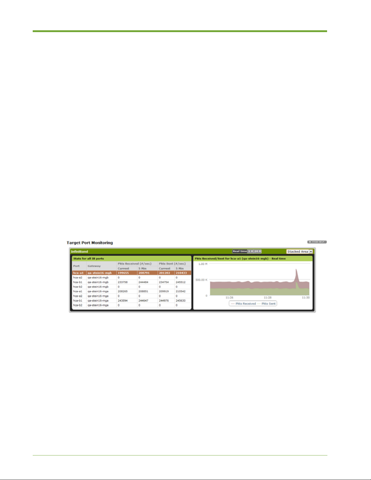
Analyzing Data for a Target
Y ou can analyze tar get data in real-time or as historical trends, and choose from a variety of display
formats.
To analyze data for a selected target port, do the following:
1. Select Monitor > Monitor Targets. The Target Port Monitoring page appears.
2. Choose a target port, as described in Selecting a Target Port on page 61.
3. Select one of the following time intervals for data analysis:
— Real Time Displays data as it happens, in real time
—
1 H Displays aggregated data for the last hour
—
24 H Displays aggregated data for the last 24 hours
4. Choose the graph type from the drop-down list on the right.
Line
•
• Area
• Stacked Line
• Stacked Area
The following example shows port data using a Stacked Area graph.
Administration
The Administration page of the HP VMA Web Interface provides a single point of contact where
you can perform a wide range of SAN Gateway administration tasks.
You must have Admin privileges to perform the following tasks using the Administration function
pages.
62 HP VMA SAN Gateway User’s Guide AM456-9026A
Page 63

:
Function Page Tasks
Cluster Admin • Viewing Software Version and Boot Images on pa ge 64
• Rebooting or Shutting Down a Node on page 64
• Changing and Saving Configuration Files on page 65
• Viewing Gateway Node Details on page 66
• Viewing Alerts on page 66
• Searching for and Viewing Logs on page 67
• Viewing Node Versions on page 68
Network • Viewing Current Network Settings on page 69
• Changing the Gateway Management Virtual IP Address on page
70
• Modifying Global Default Gateway Settings on page 70
• Viewing and Modifying DNS Settings on page 70
• Viewing and Modifying NTP Settings on page 72
• Viewing and Modifying Web Admin Settings on page 73
• Viewing Gateway Node Details on page 66
Notification • Specifying Call Home Settings on page 76
• Managing User Accounts on page 76
• Managing E-mail Settings on page 79
• Managing E-mail Notifications on page 83
• Managing SNMP Settings on page 84
• Managing SNMP Traps on page 87
Tools • Adding and Removing Feature Licenses on page 88
Information • Accessing Context-Sensitive Help on page 90
• Viewing System, License, and Copyright Information on page 90
• Viewing System, License, and Copyright Information on page 90
Cluster Admin
Cluster administration includes configuration and management tasks for the nodes in a SAN
Gateway cluster. A cluster generally consists of two SAN Gateway nodes, a master node and a
standby.
The Master SAN Gateway is the current master node in the cluster. The master node works to gether
with a standby node to manage the availability of the cluster. When t here are more than two nodes
in the cluster, the other nodes are designated as normal nodes.
AM456-9026A HP VMA SAN Gateway User’s Guide 63
Page 64
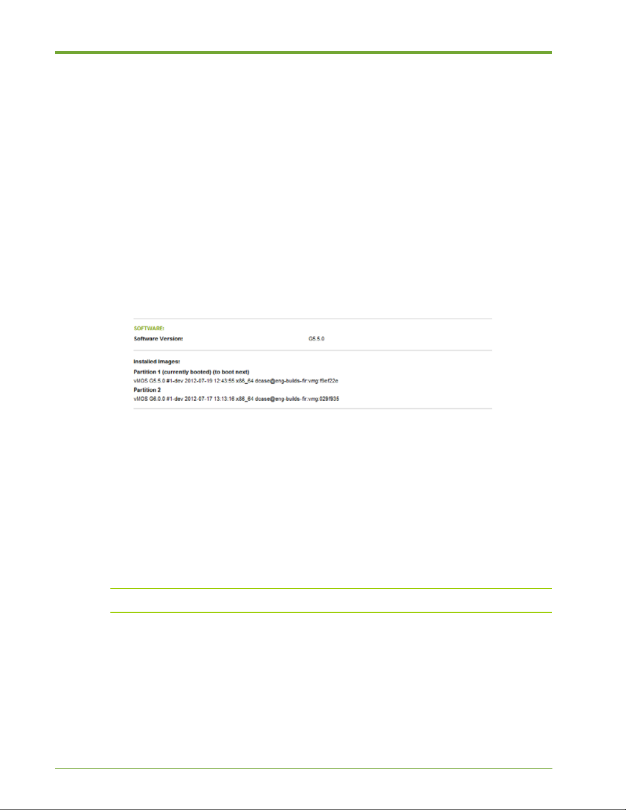
In the case of failure of both the master node and the standby node, the cluster continues to operate
by electing a new master from the list of available nodes.
Viewing Software Version and Boot Images
The Software section of the Cluster Admin page shows the current software version running on the
SAN Gateways, as well as the boot images. Two boot images are installed for each SAN Gateway,
each in a separate partition.
To view the software version and choose a boot image, do the following:
1. Select Administration > Cluster Admin > Reboot.
2. To view the version of software running on the SAN Gateway, look at the Software Version
section of the Software panel.
3. To view the installed boot images, look at the Installed Images section of the Software panel.
Rebooting or Shutting Down a Node
You can reboot o r shut down a SAN Gateway node through the HP VMA Web Interface.
• Shutdown—Stops a SAN Gateway node or removes the node from the SAN Gateway cluster
for planned maintenance or upgrade.
• Reboot—Restarts a SAN Gateway node, clearing its data but retaining the existing
configuration settings. In a cluster, the standby SAN Gateway takes over while the previously
active master node reboots.
Caution: Rebooting a SAN Gateway node may cause a temporary decline in overall performance.
To reboot or shut down a SAN Gateway node, do the following:
1. Select Administration > Cluster Admin > Reboot.
The Cluster Administration page displays information on the current software version, the
installed software image, and configuration files. Two boot images are installed for each SAN
Gateway in separate partitions.
Note: Rebooting the system will take several minutes to complete.
64 HP VMA SAN Gateway User’s Guide AM456-9026A
Page 65

2. Do one of the following:
— T o reboot the system, click Reboot. In a cluster configuration, the standby SAN Gateway takes
over while the master reboots.
— T o shut down the system, click
takes over when the master is shut down.
Shutdown. In a cluster configuration, the standby SAN Gateway
A pop-up dialog appears.
3. Click OK to continue with the reboot process, or Cancel to quit without rebooting or shutting
down the system.
WARNING! After the system is shut down, you will have to manually power it back on, or use the iLO
interface to power on.
Changing and Saving Configuration Files
You can save the current SAN Gateway configuration to a specified file, apply a previously saved
configuration to the SAN Gateway cluster (whether a local file or on a remote server), and delete
old configuration files.
The currently active configuration is marked as Active in the configuration table. The Status
column indicates which configuration file is active. The active file is backed up as
<filename>.bak.
To save, apply, or delete a SAN Gateway configuration file, do the following:
1. Select Administration > Cluster Admin > Reboot.
2. To apply a previous configuration to the SAN Gateway, select the check box next to the
Config Name and click Apply.
3. To save the current SAN Gateway configuration, enter a unique name in the Save
configuration as field, and click Save.
4. To delete a configuration, select the check box next to the Config Name and click Delete.
AM456-9026A HP VMA SAN Gateway User’s Guide 65
Page 66
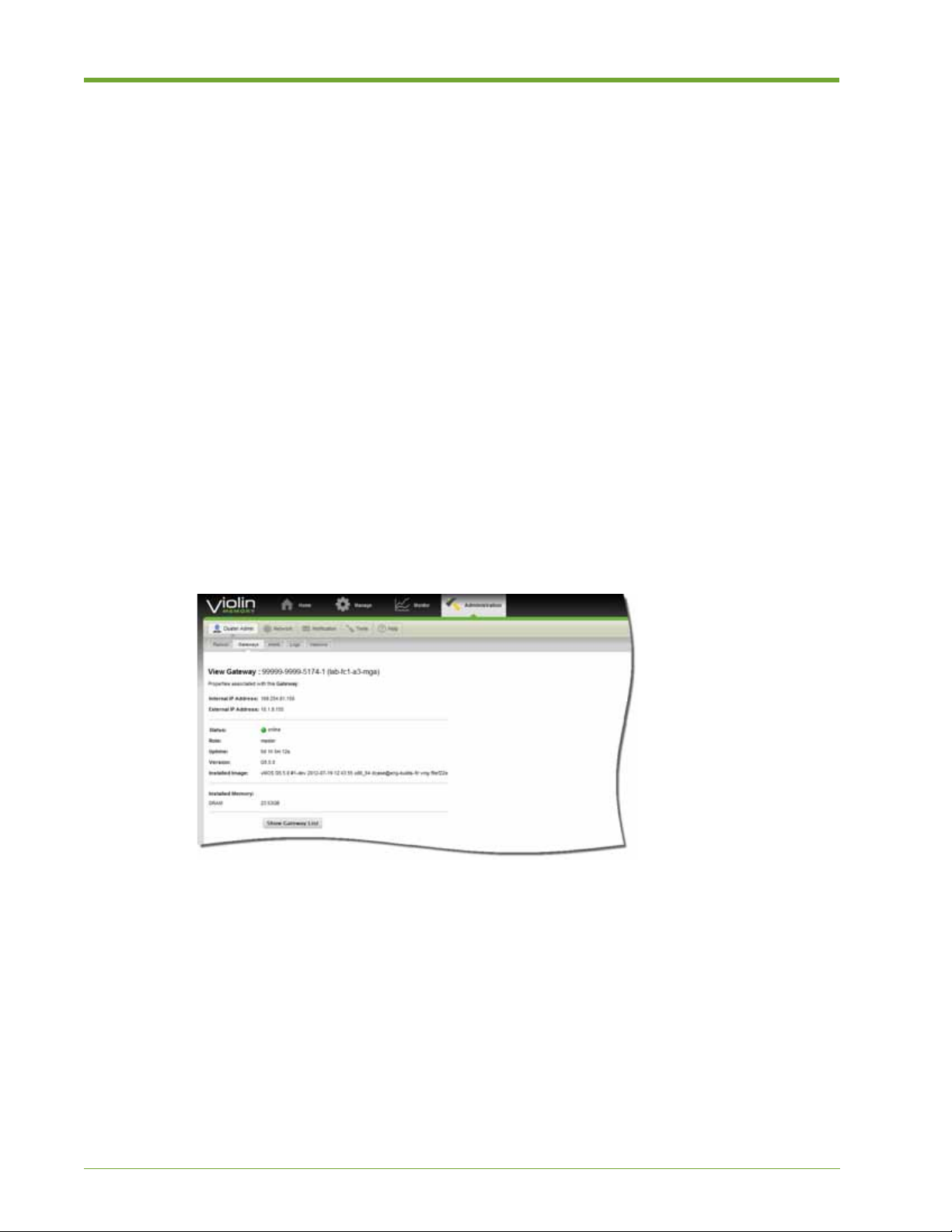
Viewing Gateway Node Details
The Gateways page lists all the SAN Gateways (nodes) in the management cluster, their status
(online/offline), their role (master node, standby node, normal node), and notification of unsaved
changes
To view SAN Gateway node details, do the following:
1. Select Administration > Cluster Admin > Gateways.
The Gateways page displays a list of active nodes. If the management cluster has too many
nodes to display on one page, click the Next to page forward and Prev to go back.
2. To change the number of nodes displayed per page, select a number from the Display drop-
down list and click Apply. The range of display alerts appears between the Prev and Next
hyperlinks.
3. To view detailed information on a particular node, click the Gateway node link in the list.
The View Gateway page shows the internal and external IP addresses, the node’s role and
status, uptime, software version, and the name of its installed image. The page also shows the
amount of DRAM installed on the node.
4. Click Show Gateway List to return to the list of Gateway nodes.
Viewing Alerts
The Alerts page shows a listing of current and past system events that triggered an alert. Select the
types of alerts to display (informational, warning, or error) and click the APPLY button.
To view cluster alerts, do the following:
1. Select Administration > Cluster Admin > Alerts.
66 HP VMA SAN Gateway User’s Guide AM456-9026A
Page 67

2. To change the types of alerts that appear in the list, deselect or select the check box next to the
Show icon: Info, Warning, Error. A check mark indicates that the alert type is selected to
appear in the list.
3. Click the Next to page forward through the list and Prev to go back.
4. To change the number of alerts displayed on a page, choose a number from the Display drop-
down list and then click Apply.
5. To sort based on the values in a column, click the column heading. Click the heading a second
time to reverse the sorting order.
Searching for and Viewing Logs
The Web Interface allows you to easily view a listing of logged events. You can choose between
viewing current and historical logs in paginated format. Log files are rotated once a day.
Note: You can only view logs for the current master gateway using the HP VMA Web Interface.
To view logs, do the following:
1. Select Administration > Cluster Admin > Logs.
2. To navigate to the desired log page, do any of the following:
—Click Next (>) to page forward through the log files and Prev (<) to go back a page.
— Click the double greater-than arrows (>>) to jump to the last page, and the double less-than arrows
(<<) to jump back to the first page.
— Enter a log page number in the
AM456-9026A HP VMA SAN Gateway User’s Guide 67
Go to Page text field and press Enter to go directly to a page.
Page 68

3. To go to the most recent log entries, click the double arrow icon (>>) last available page in the
log and scroll to the bottom.
4. To view a historical log, or to return to the current log after viewing another one, click the Log
File field, select a file from the drop-down list, then click Apply.
Note: The Lo g File field displays the top file in the drop-down list (“Current log”). It does not display
the name of the log file that you are viewing, which appears directly below the Log File field.
Viewing Node Versions
The Versions page shows the software version running on each SAN Gateway and identifies the
current boot image. It also shows how long each SAN Gateway has been running (Uptime) and
identifies the boot SAN Gateway and next SAN Gateway to be booted (Boot/Next).
To view version details for a SAN Gateway node, do the following:
1. Select Administration > Cluster Admin > Versions. The Versions page appears with a list of
active nodes and the following information for each:
— Gateway ID: Node name
— Uptime: How long each node has been running
— Version: Software version running on the node
— Boot/Next: The boot SAN Gateway and next SAN Gateway to be booted
68 HP VMA SAN Gateway User’s Guide AM456-9026A
Page 69

— HP VMA Cluster ID String: Current boot image
2. View more details on a node, click the Gateway ID link on the left. The View Gateway page
appears, as described in Viewing Gateway Node Details on page 66.
Network
The Network Web Interface pages provide network configuration information for the SAN
Gateway, and allows you to manage the cluster IP address and global default gateway.
The tasks you can perform on these pages are intended for network administrators, and require
Admin user access privileges. The management VIP address (also known as the virtual IP address,
or VIP) is the IP address for the SAN Gateway.
Viewing Current Network Settings
The Network Settings page allows you to view and modify network settings from one central
location.
To view current network settings, do the following:
1. Select Administration > Cluster Admin > Network > Network Settings. The Network
Settings page appears.
2. Verify the Cluster Management Address and Network Mask Length.
The VIP address for gateway management is set as part of the initial out-of-the box
configuration. You can change the cluster management IP address and network mask length in
this section, but it is not recommended. Consult with your network architect before changing
these values.
3. Review the Bonding Mode setting.
This refers to Network Interface Bonding. For more information on bonded interfaces, see
Network Bond Commands on page 183.
4. Review the Routing settings.
This is the address for the default global gateway. You can enable and disable the gateway and
set a new address for the default gateway.
5. Review the cluster Static and Dynamic Routes.
AM456-9026A HP VMA SAN Gateway User’s Guide 69
Page 70

This is the routing information for the SAN Gateway, including destination, mask, gateway,
whether the node is active or static, and the interface.
Changing the Gateway Management Virtual IP Address
You can change the gateway management virtual address (also known at the virtual IP address or
VIP) from the Network Settings page. In most cases, it is recommended that you change the cluster
management address through a serial console using the CLI. However, there are few situations
where changing the management VIP address through the Web Interface is advised, one being in
preparation for a physical move of the devices.
Note: Consu lt with your network administrator before changing the management VIP address. If you
change this address through the Web Interface, you lose connectivity with the gateway.
To change the cluster management VIP address, do the following:
1. Select Administration > Cluster Admin > Network > Network Settings. The Network
Settings page appears.
2. In the Cluster Management Address panel, enter an IP Address in the text field.
3. Enter the Network Mask Length in the text field.
4. Click Apply.
Modifying Global Default Gateway Settings
The Network Settings page allow you to specify the Global Default Gateway and then enable or
disable its use.
To modify the global default gateway, do the following:
1. Select Administration > Cluster Admin > Network > Network Settings. The Network
Settings page appears.
2. To disable the current global default gateway, click Disable. To re-enable the default gateway,
click Enable.
3. To change the global default gateway, enter the new default gateway address in the text field
and click Set Default Gateway.
Viewing and Modifying DNS Settings
You can view domain name server (DNS) configurations, add DNS servers, as well as add and
remove domain names from the DNS Settings page.
70 HP VMA SAN Gateway User’s Guide AM456-9026A
Page 71

Note: If one or more IP addresses for DNS servers were set up as part of the initial out-of-the-box
setup, they are listed on this page.
To view configured DNS settings, do the following:
1. Select Administration > Network > DNS Settings.
2. Go to the DNS Servers panel at the top of the window to view information on the DNS servers
that were configured as part of the initial out-of-the-box setup.
To add and modify name servers, do the following:
1. Select Administration > Network > DNS Settings.
2. T o modify a configured name server , go to the Add or Modify Name Servers panel and change
the Primary DNS IP address displayed in the text box.
3. To add a second name server, enter an IP address in the Secondary DNS IP address text box.
4. To a dd a third name server, enter an IP address in the Terciary DNS IP address text box.
5. Click Apply.
To add and remove domain names, do the following:
1. Select Administration > Network > DNS Settings.
2. To remove an existing domain name, go to the Domain Names panel and select the domain
name from the list. The selected name highlights.
AM456-9026A HP VMA SAN Gateway User’s Guide 71
Page 72
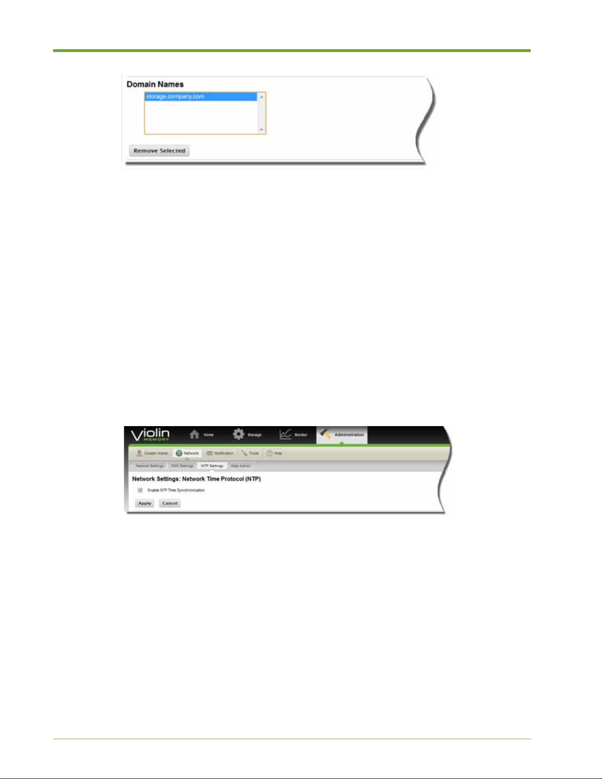
3. Click Remove Selected.
Viewing and Modifying NTP Settings
The Network Time Protocol (NTP) is a networking protocol for synchronizing the clocks of
computer systems over data networks. You can enable or disable NTP synchronization and ad d or
remove an NTP server through the NTP Settings page.
When you initially go to the NTP Settings page, information for the NTP server that was configured
in the out-of-box setup is shown.
To enable or disable NTP time synchronization, do the following:
1. Select Administration > Network > NTP Settings.
2. To enable NTP, click the Enable NTP Time Synchronization check box. A check mark
appears to show it is enabled. Then click Apply.
3. To disable NTP time synchronization, click the check marked Enable NTP Time
Synchronization check box. The check mark disappears to show that it is disabled. Then click
Apply.
To enable, disable, or remove an NTP server, do the following:
1. Select Administration > Network > NTP Settings.
2. To e nable an NTP se rver, click the chec k box next the server name in the NTP Servers panel.
Then, click Enable Server.
72 HP VMA SAN Gateway User’s Guide AM456-9026A
Page 73

3. To disable an NTP server, click the check box next server name in the NTP Servers panel.
Then, click Disable Server.
4. To re move an NTP server, click the check box next server name in the NTP Servers panel.
Then click Remove Selected Server.
To add an NTP server, do the following:
1. Select Administration > Network > NTP Settings.
2. Go to the Add New NTP Server panel and enter the new NTP Server IP address in the text
box.
3. Select a Version from the drop-down list:
•
3—Network Time Protocol (Version 3)
• 4—Network Time Protocol (Version 4)
Note: Ask your network administrator, if you are unsure which version to choose.
4. Specify whether or not you want the new NTP server enabled or disabled by choosing Yes or
No from the drop-down list.
5. Click Add NTP Server to add the server to the network.
Viewing and Modifying Web Admin Settings
Y ou can change W eb Interface configurations, disable the HP VMA W e b Interface, configure HTTP
and HTTPS, set the inactivity time for automatic logouts, configure cookies, and show the HP VMA
Web Interface configuration settings.
Caution: Disabling the HP VMA W eb Interface terminates your Web session, after which you can only access
the SAN Gateway cluster through the command line interface. For information of the CLI, see APPENDIX
A, “VMA SAN Gateway Command Line Interface Reference” on page 141.
AM456-9026A HP VMA SAN Gateway User’s Guide 73
Page 74
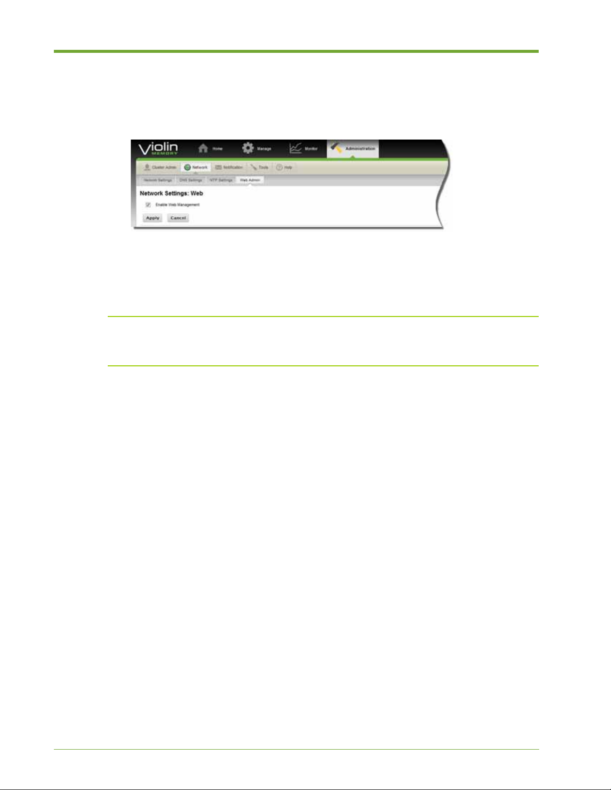
To disable Web management, do the following:
1. Select Administration > Network > Web Admin. The Network Settings page appears.
Note: Web Management must be enabled by default, or you wouldn’t be able to access the HP
VMA SAN Gateway cluster through the Web Interface.
2. To disable Web Management, click the Enable Web Management check box to deselect this
feature. The check mark disappears, turning off the function.
3. Click OK to disable Web Management.
Note: After you disable the HP VMA Web Interface, the only way to access the Web Interface again
is to use the
web enable command in the CLI. For more information, see APPENDIX A, “VMA
SAN Gateway Command Line Interface Reference” on page 141.
To set Web configurations, do the following:
1. Select Administration > Network > Web Admin. The Network Settings page appears.
74 HP VMA SAN Gateway User’s Guide AM456-9026A
Page 75
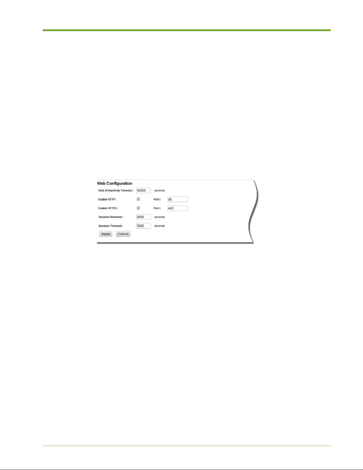
2. Go to the Web Configurations panel, and specify the following options:
• Auto Logout Timeout (secs)
connection to the HP SAN Gateway cluster after a specified period of inactivity. The default auto
logout timeout is 9000 seconds (15 minutes).
—Enables automatic logout and disconnect of the Web Interface
• Enable HTTP—Enables (or disables) HTTP on the specified port.
• HTTP Port—Port 80 is the default. Change this to a different free and unused port to access the
HP VMA Web Interface in the following format:
http://<Management IP address <port#>/
• Enable HTTPS—Enables (or disables) HTTPS on the specified port.
• HTTPS Port—The default is 443. Change it to another available port as described in HTTP Port
setting above.
• Web Session Renewal (secs)—Time in seconds before the HP VMA Web Interface session
cookie expires.
• Web Session Timeout (secs)—Time in seconds before the HP VMA Web Interface session
cookie times out.
3. Click Apply to save the configurations, or Cancel to return to the previous settings.
Notification
Web Interface notifications provide a means of delivering messages to a set of recipients when an
event or alert occurs. For example, an e-mail can be sent to the administrator when the chassis
internal temperature exceeds a specified threshold.
The Notification function allows you to manage the following:
• Call Home
• Users
• Email Settings
• Email Events
• SNMP Settings
• SNMP Events
AM456-9026A HP VMA SAN Gateway User’s Guide 75
Page 76

Specifying Call Home Settings
The Email (Call Home) Settings page allows you to enable email alerts in the following ways:
• Auto Support—Enables the HP VMA SAN Gateway clus ter to report alerts and critical events
to a specified email address. Auto Support requires an SMTP server and email domain name.
• Fault Reporting—Specifies the SMTP server and mail domain name used for call-home
messages. These settings are also used for alerts.
To enable auto support and fault reporting, do the following:
1. Select Administration > Notification > Call Home.
2. Select the Enable Auto Support Notifications check box. A check mark appears. T o turn this
feature off, select the check box again. The check mark disappears.
3. In the Fault Reporting section, enter an SMTP Server address in the text field, such as
callhome.example.com.
4. Enter the Mail Domain Name in the text field.
5. Click Apply.
Managing User Accounts
User Management displays the name, role, email address, and password status of each user account
for the HP VMA SAN Gateway cluster. This section demonstrates how to perform the following
tasks:
• Adding a User and Specifying a Role on page 77
• Changing an Account Password on page 77
• Editing a User Account on page 78
• Deleting a User Account on page 79
76 HP VMA SAN Gateway User’s Guide AM456-9026A
Page 77

Understanding User Roles and Privileges
A user’s assigned role determines the level of privileges they have in accessing and administering
the HP VMA SAN Gateway cluster. Some of parameters are only visible or configurable by users
with certain roles (privileges). The available roles and their privileges are as follows:
User Role Privileges
admin A user who can perform all administration and
configuration tasks.
monitor A user who can only access pages that show status
information for monitoring purposes.
Table 2.6 User Roles and Privileges
Adding a User and Specifying a Role
An Admin user can add new users and define their account privileges.
To add a new user account and define the access privileges, do the following:
1. Select Administration > Notification > Users.
2. At the bottom of the page, click Add New User. The Add New User dialog appears.
3. Specify the following account information:
• User Name:
Enter a user name for login credentials.
• Role: Select a role from the drop-down list, admin or monitor. For more information, see
Understanding User Roles and Privileges on page 77.
4. Click OK to add the new account, Cancel to abort the action, or Reset to clear the fields and
start over.
Changing an Account Password
An Admin user can set or reset the passwords and define access privileges for other user accounts.
To add a new user account and define the access privileges, do the following:
1. Select Administration > Notification > Users.
2. Next to the user name, click Change Password. The Change Password dialog appears.
3. Specify the following information:
AM456-9026A HP VMA SAN Gateway User’s Guide 77
Page 78
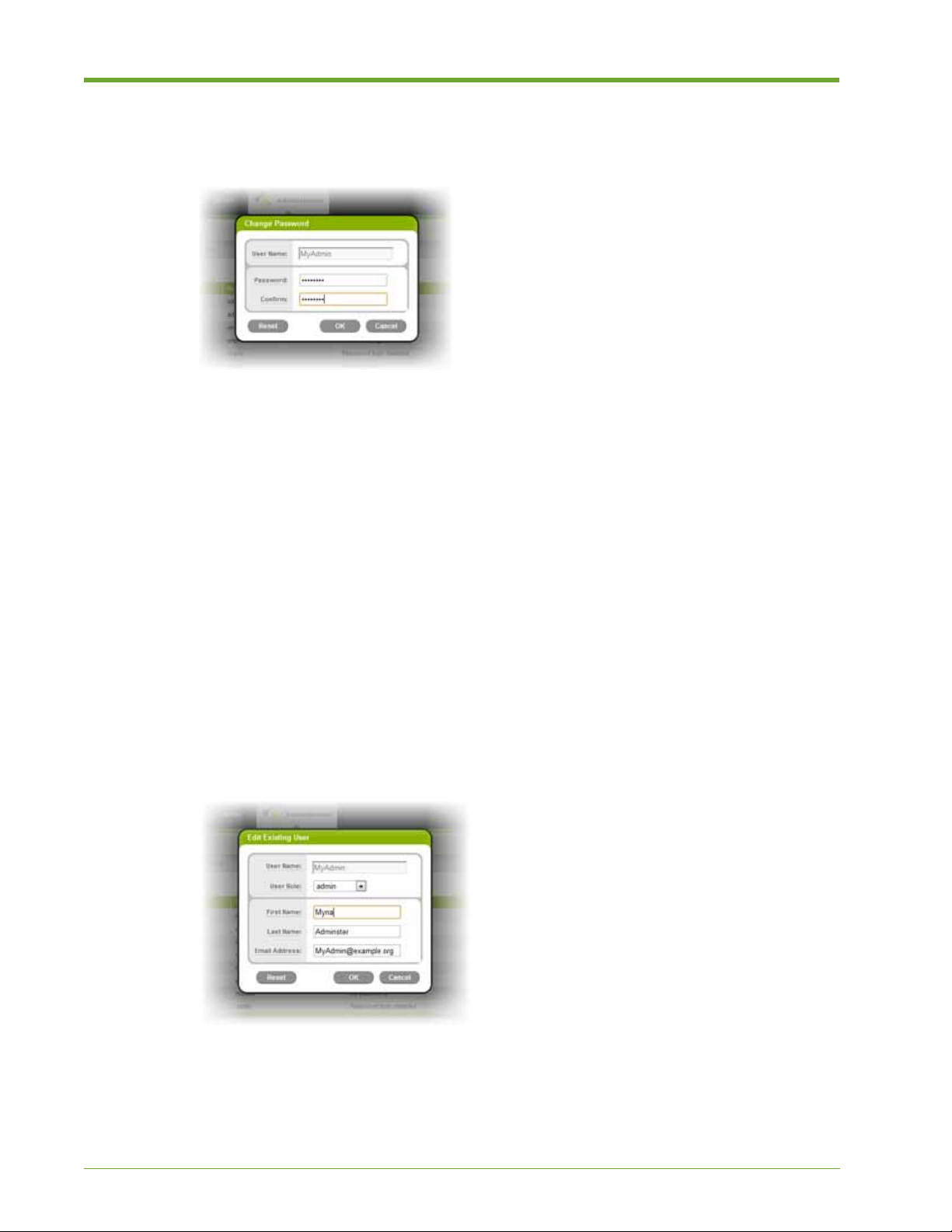
• User Name: Enter the user name for the login credential.
• Password: Enter the new password.
• Confirm: Re-enter the new password.
4. Click OK to accept the change, Cancel to abort the action, or Reset to clear the fields and start
over.
Editing a User Account
An Admin user can change an existing user account, modifying personal and contact information.
To edit an existing user account, do the following:
1. Select Administration > Notification > Users.
2. Click Edit for the desired user. Edit User dialog appears.
3. Change the following account information, as necessary:
• Role:
Select a role from the drop-down list, admin or monitor. For more information, see
Understanding User Roles and Privileges on page 77.
• First Name: Enter the user’s first name.
• Last Name: Enter the user’s last name.
• Email Address: Enter the user’s email address.
4. Click OK to accept the changes, Cancel to abort the action, or Reset to clear the fields and
start over. If you accept the changes, another dialog appears.
78 HP VMA SAN Gateway User’s Guide AM456-9026A
Page 79

5. Click OK in the confirmation dialog to save the changes. The results appear in the User
Management panel.
Deleting a User Account
An Admin user can delete the accounts of other users.
To delete a user account, do the following:
1. Select Administration > Users.
2. Click Delete next to the account name you want to remove. A confirmation dialog appears
.
3. Click Yes to confirm you choice, or No to cancel the action. If you click Yes, the user account
is deleted from the list.
Managing E-mail Settings
You can configure email settings and addresses to receive alerts from the vSHARE cluster. Call
Home settings are used to send the alerts. For information on how to enable Call Home settings, see
Specifying Call Home Settings on page 76.
This section demonstrates the following:
• Enabling Email Alerts on page 80
• Configuring the Email Server on page 80
• Configuring SMTP Authentication on page 81
• Managing Alert Recipients on page 82
AM456-9026A HP VMA SAN Gateway User’s Guide 79
Page 80

Enabling Email Alerts
You can specify whether or not to receive alerts from the vSHARE cluster. Call Home Settings
entries are used to send the alerts. For information on how to enable Call Home settings, see
Specifying Call Home Settings on page 76.
To enable email alerts, do the following:
1. Complete the task as described in To enable auto support and fault reporting, do the following:
on page 76.
2. Select Administration > Notification > Email Settings.
3. In the top section of the Email Settings page, select the Enable Email Alerts check box.
4. Click Apply to accept, or Cancel to deactivate the setting.
5. Go on to complete Configuring SMTP Authentication on page 81.
Configuring the Email Server
You can configure the email server that handles event notifications in the
Note: Go to Managing E-mail Notifications on page 83 for information on how to specify the types
of events for which you want to be notified.
To configure the email server for notifications, do the following:
1. Select Administration > Notification > Email Settings.
2. In the Email Configuration panel, specify the following information:
• Mail Hub:
callhome.example.com.
Enter the mail hub fully qualified domain name (FQDN), such as
• Mail Hub Port: Enter the port number for the mail hub.
• Mail Return Address: Enter an email return address. Use do-not-reply, if you do not want to
receive responses to alert notifications.
• Mail Return Domain Name: Enter a domain name for return mail, or leave blank to use the
system domain name.
80 HP VMA SAN Gateway User’s Guide AM456-9026A
Page 81
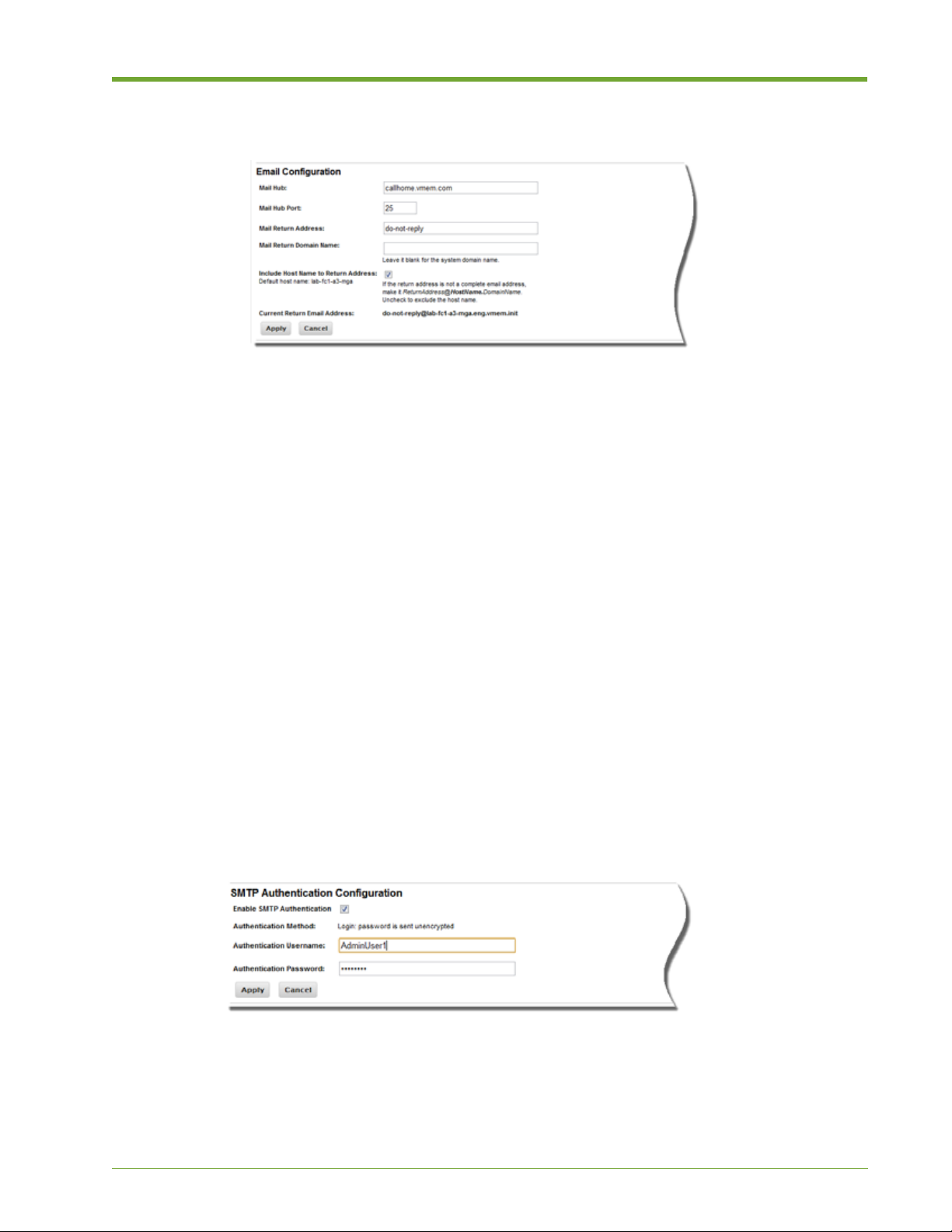
• Include Host Name to Return Address: Clear this check box to remove the host name from
the return email address.
3. Click Apply to accept the Current Return Email Address, or Cancel to modify the return
email address using the previously described fields.
4. Go on to complete Configuring SMTP Authentication on page 81.
Configuring SMTP Authentication
SMTP Authentication (SMTP AUTH) is an extension of the Simple Mail Transfer Protocol
(SMTP). When enabled, an SMTP client logs in using an authentication mechanism supported by
the SMTP server.
The following task demonstrates how to set up SMTP authentication for the e-mail server from
which email alerts will be sent.
To configure SMTP authentication, do the following:
1. Select Administration > Notification > Email Settings.
2. In the SMTP Authentication Configuration panel, select the Enable SMTP Authentication
check box. A check mark appears, showing that SMTP Authentication turned on.
3. Enter the following information in the appropriate text fields:
Authentication Username: The user name for the authentication credentials
•
• Authentication Password: The password for the authentication credentials
4. Click Apply to save your configuration entries, or Cancel to delete them and start over.
5. Go on to complete Managing Alert Recipients on page 82.
AM456-9026A HP VMA SAN Gateway User’s Guide 81
Page 82

Managing Alert Recipients
The Alert Recipient Management section shows information about the current e-mail notification
recipient, if one is configured.
You can edit the account for an existing alert recipient, add new recipients, delete recipients, and
send test e-mails to recipients.
To edit, delete, add and verify alert recipients, do the following:
1. Select Administration > Notification > Email Settings, and go to the Alert Recipient
Management panel.
2. T o edit an existing alert recipient click Edit next to the recipient’ s name, then in the dialog that
appears, specify the following:
• Recipient Email Address:
needed.
Enter a new email address for the recipient in the text field, if
• Get Details? Select this check box to receive alerts as specified by the Call Home Settings page,
or deselect the check box to turn off this option.
• Get Infos? Select this check box to receive less urgent informational events, or deselect the check
box to turn off this option.
• Get Failures? Select this check box to receive notifications on failure events (such as file system
errors, process crashes, and unexpected shutdowns), or deselect the check box to turn off this
option.
• Click OK to activate the request, Cancel to abort the request, or Reset to clear the fields and start
again.
3. T o add a new recipient click Add a New Recipient, then in the dialog that appears, specify the
following:
• Recipient Email Address:
Enter an email address for the recipient in the text field, if needed.
• Get Details? Select this check box to receive alerts as specified by the Call Home Settings page,
or deselect the check box to turn off this option.
• Get Infos? Select this check box to receive less urgent informational events, or deselect the check
box to turn off this option.
82 HP VMA SAN Gateway User’s Guide AM456-9026A
Page 83

• Get Failures? Select this check box to receive notifications on failure events (such as file system
errors, process crashes, and unexpected shutdowns), or deselect the check box to turn off this
option.
• Click OK to activate the request, Cancel to abort the request, or Reset to clear the fields and start
again.
4. To delete an alert recipient click Delete next to the recipient’s name, then in the dialog that
appears click OK to confirm or No to cancel the action.
5. To se nd a test email to all alert recipients, click Send Test Email and OK to approve, or
Cancel to abort the task.
Managing E-mail Notifications
You can individually select from the types of e-mail notification events you want to receive. The
notifications are sent to specified alert recipients, as described in Managing Alert Recipients on
page 82.
Selecting Email Events
You can intuitively select notification events to be sent to alert recipients as specified in Managing
Alert Recipients on page 82.
To select events for email notification, do the following:
1. Select Administration > Notification > Email Events.
2. Select the desired events from the list using the following actions:
Expand and collapse a category by clicking the arrow next to its name, or click Show All to view
•
all events or
Hide All to collapse all categories.
• Choose from the following global event actions:
Select All: Selects all events
Select None: Deselects all events
Reset Defaults: Returns to system default selections
AM456-9026A HP VMA SAN Gateway User’s Guide 83
Page 84

• Select individual events in a category by clicking the check box next to the name. A check mark
appears when the event is selected. Select the event again to deselect the event and remove the
check mark.
• Select all the events in a category by clicking the check mark icon on the right side of the header.
• Deselect all selected events in a category by clicking the X icon on the right side of the header.
• Reset the selections for a category to the default selections by clicking the star icon on the right side
of the header.
3. Click Apply to accept your selections, or Cancel to return to the previous settings.
Managing SNMP Settings
You can individually configure several types of SNMP settings through the Web Interface. Simple
Network Management Protocol (SNMP) is an Internet standard protocol for managing and
monitoring devices on an IP network. For more information, see APPENDIX C, “SNMP T raps” on
page 229.
This section covers the following:
• Enabling SNMP Management on page 84
• Configuring SNMP on page 85
• Setting SNMP Trap Sinks on page 86
Enabling SNMP Management
You can interactively enable and disable SNMP Management from the SNMP Settings page.
To enable or disable SNMP management on your system, do the following:
1. Select Administration > Notification > SNMP Settings.
2. In the upper panel, select the Enable SNMP Management check box. A check mark appears
to show SNMP Management is turned on.
84 HP VMA SAN Gateway User’s Guide AM456-9026A
Page 85

3. To disable SNMP Manageme nt, select the check box again. The check mark disappears.
4. Click Apply to activated your selection, or Cancel to return to the previous state.
Configuring SNMP
You can configure SNMP, including settings for the Read-only Community and SNMP Traps
Community.
• An SNMP TRAP is a message that is sent out when a significant system event is detected. A
trap sink community defines a host and a community string pair. The community string is the
most basic form of SNMP security.
• SNMP community strings are like passwords for network elements. One community string is
often used for read-only access with the default set to “public.” The read-only string is used for
the transfer of data between devices.
• A read-write community string is used less often, with a default value of “private.” The read-
write community string provides the ability to change MIB variables on the device.
To configure SNMP settings, do the following:
1. Select Administration > Notification > SNMP Settings.
2. In the SNMP Configuration panel, enter the following information the appropriate text fields:
• SNMP Port:
The port number assigned for SNMP traffic
• System Location: IP address of the SNMP server
• System Contact: The email address for the system administrator
3. Enable or disable the following options by selecting the check box next to the option, then
from the drop-down list choose between Public, or Private:
• Read-Only Community
• SNMP Traps Community
4. Click Apply to activated your selection, or Cancel to return to the previous state.
AM456-9026A HP VMA SAN Gateway User’s Guide 85
Page 86

Setting SNMP Trap Sinks
A trap sink defines a host and a community string pair. When a trap event occurs the SNMP agent
sends out a trap to each host in the trap sink list using the community string. This section shows you
how to configure a trap sink list, by removing, enabling, disabling, and adding SNMP servers
(hosts) to be included in the list.
The SNMP Trap Sinks panel lists configured SNMP servers, their type-version (type of security
implemented as related to the version of SNMP), if SNMP management is enabled or not, and the
community configuration. For more information on the available SNMP traps, see Available Traps
on page 234.
To remove, enable, or disable SNMP trap sink servers, do the following:
1. Select Administration > Notification > SNMP Settings.
2. To remove an SNMP server, do the following:
a. Go to the SNMP Trap Sinks panel.
b. Select the SNMP server from the list.
c. Click Remove Selected Server.
3. To enable or disable an SNMP server, do the following:
a. Go to the SNMP Trap Sinks panel.
b. select the SNMP server from the list.
c. Click Enable Server or Disable Able Server.
To add new SNMP Trap Sinks, do the following:
1. Select Administration > Notification > SNMP Settings.
2. Go to the SNMP Trap Sinks panel and under Add New SNMP Trap Sinks, enter the SNMP
Server IP address in the text field.
3. From the Type-Version drop-down list, choose one of the following:
• Trap-v1:
Implements community-based security
• Trap-v2: Implements party-based security
4. From the Enable Server drop-down list, choose Yes or No.
5. From the Community drop-down list, choose Public or Private. For more information on
these options, see Configuring SNMP on page 85.
86 HP VMA SAN Gateway User’s Guide AM456-9026A
Page 87

6. Click Add SNMP Server.
Managing SNMP Traps
You can individually select from all available SNMP notification events. For information on using
MIB Browsers to help manage SNMP, see Benefits of Using a MIB Browser on page 230.
Note: The notifications are sent to the email address specified on Administration > Notification >
Email Settings page. For more information, see Configuring SNMP on page 85.
Selecting SNMP Traps Events
The SNMP Traps Events page allows you to interactively select SNMP trap events for which
notifications are sent. For information on the available SNMP traps, see Available Traps on page
234.
To select events for email notification, do the following:
1. Select Administration > Notification > SNMP Events.
2. Select the desired SNMP traps events using the following actions:
Expand and collapse a category by clicking the arrow next to its name, or click Show All to view
•
all events or
Hide All to collapse all categories.
• Choose from the following global event actions:
Select All: Selects all events
AM456-9026A HP VMA SAN Gateway User’s Guide 87
Page 88

Select None: Deselects all events
Reset Defaults: Returns to system default selections
• Select individual events in a category by clicking the check box next to the name. A check mark
appears when the event is selected. Select the event again to deselect the event and remove the
check mark.
• Select all the events in a category by clicking the check mark icon on the right side of the header.
• Deselect all selected events in a category by clicking the X icon on the right side of the header.
• Reset the selections for a category to the default selections by clicking the star icon on the right side
of the header.
3. Click Apply to accept your selections, or Cancel to return to the previous settings.
Tools
• Feature Licenses
• Upgrade
• Diagnostics
Adding and Removing Feature Licenses
The Administration > Feature Licenses page allows you to add or remove feature licenses. A list
of currently installed licenses appears at the top of the window.
Adding a New Feature License
Adding a new feature requires a license key. You must obtain from your HP VMA Memory
Customer Support representative before you begin the following procedure.
To add a new feature license, do the following:
1. Select Administration > Notification > Feature Licenses.
2. In the Add New Licenses panel, enter the license key for the new features in the text box.
Note: If you are adding more than one license, enter each key on a new line.
88 HP VMA SAN Gateway User’s Guide AM456-9026A
Page 89
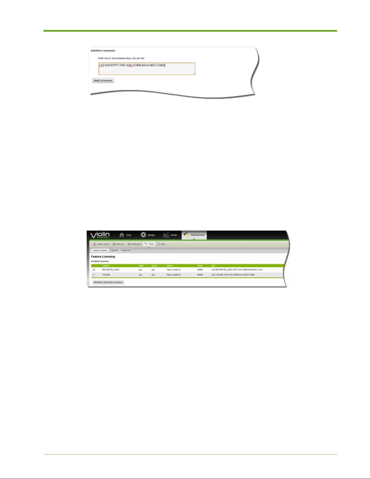
3. Click Add Licenses. The new feature license appears in the Installed Licenses panel at the top
of the window.
Removing a Feature License
You can easily remove installed feature licenses, either individually or all at once, using the
following procedure.
To remove a license, complete the following steps:
1. Select Administration > Feature Licenses.
2. In the Installed Licenses panel at the top of the window, select the check box of the licenses
you want to remove, as shown in the following example.
3. Click Remove Selected Licenses.
Information
The Information function provides easy access to the following:
• About—Shows which version of the HP VMA SAN Gateway is running and provides basic
information about trademarks and patents.
• HP VMA SAN Gateway License—Provides a complete copy of the HP VMA SAN Gateway
license.
• Acknowledgements—Lists copyright and licensing information for the open source
components of the product. Portions of this software product utilize open source copyrighted
material; attribution to copyright holders of such materials along with applicable licensing
terms are included here.
AM456-9026A HP VMA SAN Gateway User’s Guide 89
Page 90

Accessing Context-Sensitive Help
The SAN Gateway provides context-sensitive online help for each page in the Web Interface.
To access context-sensitive Help, do the following:
1. Open the Web Interface as described in Logging In to the Web Interface on page 27.
2. On the Web Interface for which you want Help, click the Page Help button in the upper right
corner of the window.
The help for that page appears, as shown in the following example.
3. Click Hide Page Help to close the Page Help panel, as shown in the previous example.
Viewing System, License, and Copyright Information
Y ou can easily access information on the system you are logged in to, your HP VMA SAN Gateway
license, as well as all copyrights and other legal notices.
To view system, license, and copyright information, do the following:
1. To view system information, select Administration > Information > About. A page appears
showing the current version of vSHARE running on your system.
90 HP VMA SAN Gateway User’s Guide AM456-9026A
Page 91

2. To view information on your HP VMA End User License, select Administration >
Information > HP VMA License.
3. To view applicable legal notices and acknowledgements for this release, select
Administration > Information > Acknowledgements.
AM456-9026A HP VMA SAN Gateway User’s Guide 91
Page 92

92 HP VMA SAN Gateway User’s Guide AM456-9026A
Page 93

CHAPTER 3 vSHARE Configuration
This chapter describes vSHARE features and functions, and the steps required to
configure a HP VMA SAN Gateway running vSHARE to manage block storage.
The following topics are covered:
• Understanding vSHARE on page 93
• Configuring Storage Containers on page 96
• Configuring Target Ports on page 99
• Configuring Initiator Groups on page 100
• Creating LUNs on page 102
• Resizing LUNs on page 105
• Exporting LUNs on page 106
• Optimizing Connectivity to Storage Arrays for Windows on page 107
Understanding vSHARE
vSHARE is a software application that provides a solution for block storage
management. vSHARE runs on a HP VMA SAN Gateway enabling host systems
(such as database servers) to use the Fibre Channel transport protocols to access
logical units of data (LUNs) stored within Memory Arrays:
On the host system, the LUN appears as a local SCSI disk. The host formats and
partitions the LUN, and the storage system sees the contents of a LUN as a set of
blocks of arbitrary data.
Administrators can use vSHARE to define rules for controlling access to LUNs
based on the containers, initiators and initiator groups, and target ports configured
within the system.
AM456-9026A HP VMA SAN Gateway User’s Guide 93
Page 94
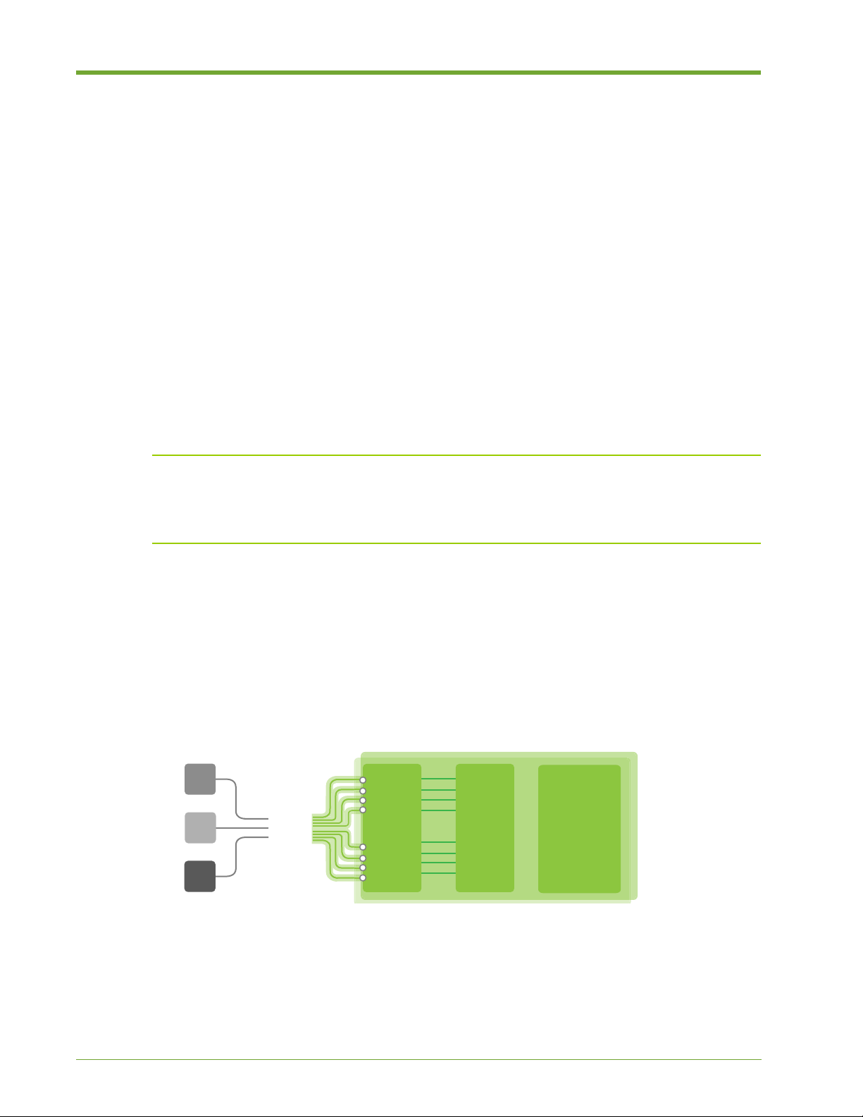
• Storage Containers: A HP VMA-series Memory Array contains a storage container;
CLUSTER
PCIe
FCP
Memory
Gateway
Memory
Gateway
VIMM VIMM VIMM
VIMM VIMM VIMM
VIMM VIMM VIMM
VIMM VIMM VIMM
VIMM VIMM VIMM
VIMM VIMM VIMM
VIMM VIMM VIMM
VIMM VIMM VIMM
VIMM VIMM VIMM
VIMM VIMM VIMM
VIMM VIMM VIMM
VIMM VIMM VIMM
VIMM VIMM VIMM
VIMM VIMM VIMM
VIMM VIMM VIMM
VIMM VIMM VIMM
VIMM VIMM VIMM
VIMM VIMM VIMM
Hosts
Memory
Array
Memory
Array
Scale-out Clustering
Provisioning API
Storage Management
currently there is a one-to-one (1:1) mapping between an array and a container (one container
per array). Every LUN created and managed by vSHARE is created within a storage container .
You can create many LUNS within a container.
• Initiators and Initiator groups: An initiator is a host or client that requires access to the
LUNs stored in a container. Multiple initiators may be grouped together in an initiator group
(igroup). Access to the LUNs in a container can be restricted to specific initiators or initiator
groups.
• Targets: A target identifies the port on the SAN Gateway through which the initiator can
access the LUNs stored in a container. Access to the LUNs in a container can be restricted by
target port.
vSHARE System Architecture
The vSHARE architecture is optimized for rapid access to and processing of large amounts of data,
including enterprise databases, data warehouses, application servers, and cloud-scale analytics.
Note: SAN Gateways running vSHARE can be deployed in a High Availability configuration,
consisting of a pair of SAN Gateways with redundant access to a HP VMA-series Memory Array.
For information on how to configure vSHARE for High A vailability , see the
Pair of VMA SAN Gateways - Process Guide.
Configuring a Redundant
A typical vSHARE cluster consists of one or more HP VMA Array running the vSHARE software
application and one or more HP VMA Arrays.
Figure 3.1 vSHARE System Architecture
The vSHARE application allows you to manage LUN and initiator-target relationships. The SAN
Gateways operate as the SAN targets and the hosts (such as a database server or application server)
are the
SAN Gateways and Memory Arrays are connected via PCIe cables.
94 HP VMA SAN Gateway User’s Guide AM456-9026A
initiators. The SAN Gateway provides network connectivity, utilizing Fibre Channel. The
Page 95
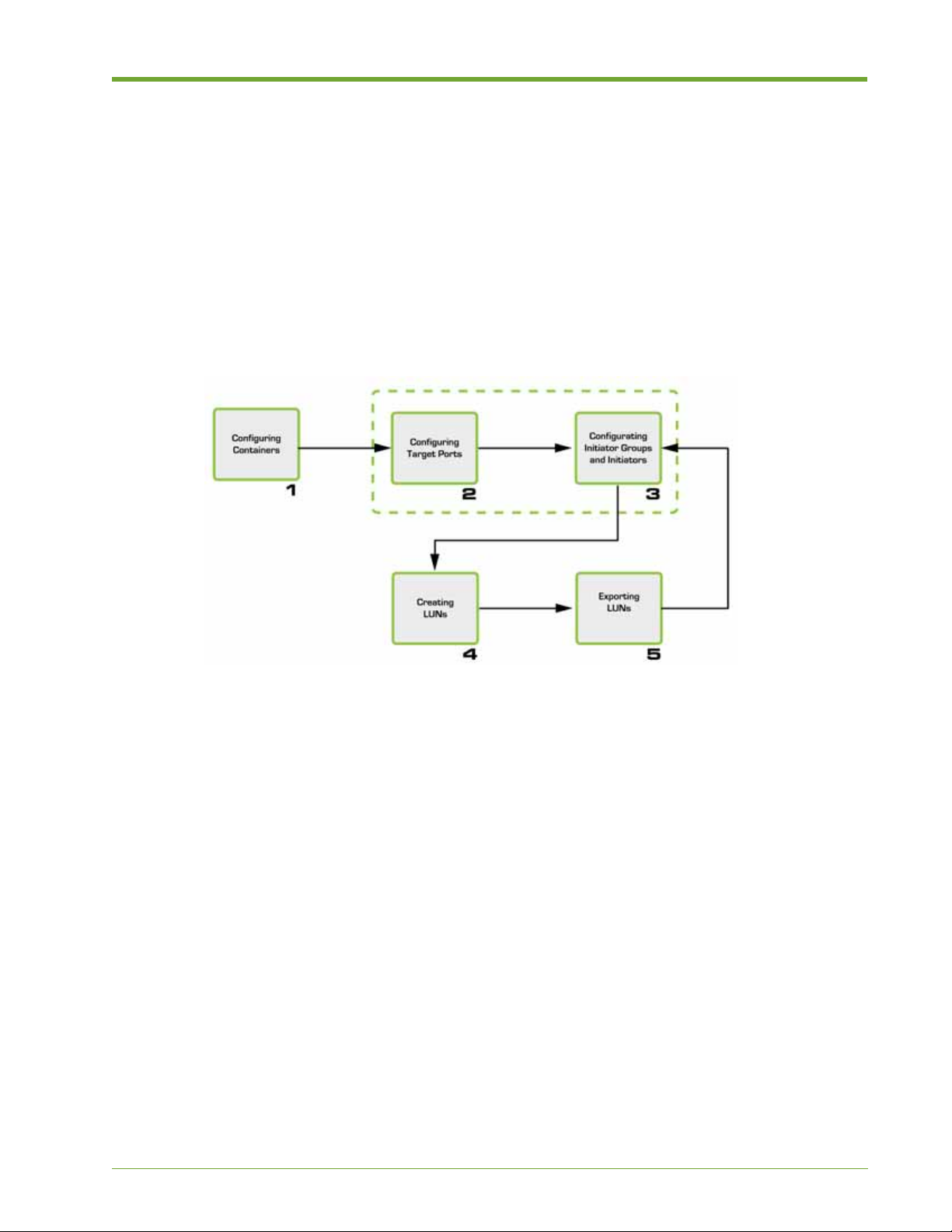
Target Ports
You can view information for target ports using the show targets command. For more
information, see show targets Command on page 100. .
vSHARE Configuration Overview
The steps to configure a vSHARE HP VMA SAN Gateway using Fibre Channel are outlined in the
following flowchart.
Figure 3.2 vSHARE Deployment Flowchart
1. Configuring Storage Containers on page 96. This step initializes the HP VMA-series Memory Array
to manage block storage and create one or two storage containers (partitions) to manage the LUNs. To
format the HP VMA-series Memory Array from vSHARE, the media init command is requ ired.
This command enables you to initialize one or more memory arrays to support block storage. Once a
memory array has been initialized to support block storage, you may create one or two storage
containers on each memory array, which may be used to store and manage LUNs.
2. (Optional) Configuring Target Ports on page 99. This step configures the target ports so they
can control access to LUNs. Configuring target ports is useful for security and bandwidth
management.
Note: Configuring target ports and initiator groups are optional steps in the vSHARE
configuration process. Organizations that do not want to use LUN-masking can control access
to LUNs through ports or switches. LUN masking is an authorization process used to make a
logical unit number available to some hosts and unavailable to others.
3. (Optional) Configuring Initiator Groups on page 100. This step configures the initiator
groups, adding one or more initiators to each initiator group. You can restrict access to LUNs
by initiator group, or on a per-initiator basis.
AM456-9026A HP VMA SAN Gateway User’s Guide 95
Page 96

4. Creating LUNs on page 102.
LUNs are created within a storage container that comprises a particular HP VMA-series
Memory Array . A LUN inherits the attributes of the container (HP VMA-series Memory Array)
in which it is created.
Note: As of this release, one container comprises a HP VMA-series Memory Array.
5. Exporting LUNs on page 106. This required step exports the LUNs to the initiator groups or
initiators via target ports. Only those initiator groups or initiators to which the LUN is
exported may access the LUN. Access may be further restricted to a specific target port.
Configuring Storage Containers
The first step in configuring a vSHARE SAN Gateway is to format the Memory Arrays to create
the necessary containers.
Note: As of this release, one container comprises a HP VMA-series Memory Array.
In vSHARE, LUNs are addressable subsets of the flash memory within a HP VMA-series Memory
Array. Every LUN created and managed by vSHARE is created within the storage container that
comprises the Array.
When a LUN is created, it is assigned to a specific container and inherits the attributes of that
container. Configuring a Storage Container follows this process:
1. Initializing HP VMA-series Memory Arrays on page 96
2. Viewing Containers on page 98
Initializing HP VMA-series Memory Arrays
T o configure a HP VMA-series Memory Array to support block storage, you must first initialize the
HP VMA-series Memory Array using the
topics:
• Command Syntax and Parameters on page 96
• Configuring Block Storage on page 97
media init command, as covered in the following
Command Syntax and Parameters
This section presents the correct command syntax for the
media init command and lists and
explains the available parameters.
96 HP VMA SAN Gateway User’s Guide AM456-9026A
Page 97

Syntax
media init device <VIOLIN_MEMORY_ARRAY_xxxxxxxxxxxxxx> type [block]
[force][name]
WARNING! Using the force option of the media init command (media init <device_name>
<block_name> force) destroys the existing data on an array. You should not use this command on a
previously initialized array without first backing up the data on the array.
Parameters
device <device>
type
name
The <device> parameter indicates the array to be initialized and is a
string of the form:
VIOLIN_MEMORY_ARRAY_xxxxxxxxxxxxxx
ata-
The type parameter defines media.
The name parameter is used to name the partition. The default is to
use the last 14 characters of the HP VMA-series Memory Array serial
number. To use a different name, add this parameter followed by a
custom name of choice. The name can be up to 14 alphanumeric
characters in length.
force
The force parameter is used to force initialization of a HP VMAseries Memory Array that has already been initialized.
Configuring Block Storage
This section demonstrates how to initialize a HP VMA Array for block storage.
To initialize the HP VMA-series Memory Array for block storage, complete the following steps:
1. Log in as administrator to the master SAN Gateway through a terminal port, such as PuTTY.
2. Enter Configure mode, using the following commands.
> enable
# configure terminal
(config) #
3. Enter the media init command to initialize the HP VMA-series Memory Array.
(config) # media init device ata-VIOLIN_MEMORY_ARRAY_23108R00000043
type block
This example generated the container ID: 23108R00000043.
AM456-9026A HP VMA SAN Gateway User’s Guide 97
Page 98

4. (Optional) Use the name parameter to create a more intuitive name for the container ID. In the
following example, the generated container ID is changed to FASTBOX1:
(config) # media init device ata-VIOLIN_MEMORY_ARRAY_23108R00000043
type block name FASTBOX1
5. Confirm that you want to initialize the HP VMA-series Memory Array.
Really initialize ata-VIOLIN_MEMORY_ARRAY_FASTBOX1 (all data will be
lost)? [no] y
A message confirms that the HP VMA-series Memory Array was successfully initialized.
media init completed successfully
SM076 [MY-vSHARE00: standby] (config) #
Viewing Containers
Before a block media device can be used for block storage, it must be enabled. Once enabled, you
can see the container. The following task shows you how to use the
enable
command to enable the device, then use the show containers command to view existing
containers.
media block id <id>
To view existing containers, complete the following steps:
1. Log in as an administrator to the master SAN Gateway attached to Port 1 of the HP VMA-
series Memory Array.
2. Enter Configure mode using the following commands.
> enable
# configure terminal
(config) #
3. Enter the media block id all enable command to enable all block containers.
(config) # media <tab>
(config) # media block id all enable
block parameter ensures that you enable vSHARE. The all parameter ensures that every
The
block container is enabled.
98 HP VMA SAN Gateway User’s Guide AM456-9026A
Page 99

4. To verify the containers were created, enter the show containers command. Information
about the containers displays.
# show containers
Container LUNs Total Free Ports HostnameA HostnameB
Status
----------------------------------------------------------------------
C-1 0 199G 199G A,B <hostname> <hostname> Single
C-2 150 199G 50176M A,B <hostname> <hostname> Single
Configuring Target Ports
The second step in configuring a vSHARE SAN Gateway is to configure the target ports. The target
ports control access to a particular LUN, which may be useful for both security and bandwidth
management.
This section covers the following topics:
• Supported Target Ports on page 99
• Configuring Fibre Channel Target Ports on page 99
Supported Target Ports
In a vSHARE system, the HP VMA-series Memory Arrays are the targets and the host system (such
as, one or more database servers or application servers) are the
initiators. The storage systems have
storage target devices, LUNs, which the hosts access through the SAN Gateway. vSHARE supports
the Fibre Channel target port type.l
Every target is a specific port on a hardware Fibre Channel host bus adapter (HBA).
• For Fibre Channel, the target ports are present when the SAN Gateway boots, if the HBAs are
installed on the system. Creating a container is not necessary.
Note: A LUN can be exported through multiple tar get ports. Active-active multipathing is supported.
Configuring Fibre Channel Target Ports
For Fibre Channel, the target ports are present when the SAN Gateway boots when the HBAs are
installed on the system.
To confirm that the vSHARE system can see the target ports prior to creating the initiator groups,
use the
ports.
show targets command. The show targets command allows you to view all target
AM456-9026A HP VMA SAN Gateway User’s Guide 99
Page 100

show targets Command
The
show targets command lists all of the target ports and their addresses (wwn), filtered by
various options.
Syntax
show targets [node <cluster node id>] [hostname <hostname>]
[protocol fc] [id <target id>] [sessions] [detail]
Parameters
[node <cluster node id>]
[hostname <hostname>]
[protocol fc]
[id <target id>]
[sessions]
[detail]
Configuring Initiator Groups
The third step in configuring the vSHARE system is to configure the initiator groups (igroups) that
identify the initiators (hosts) allowed to access a LUN or set of LUNs.
Every initiator has a protocol-specific identifier.
• Fibre Channel initiators are identified by World-Wide Names (WWN). Fibre Channel
initiators are fixed by the appropriate HBA port.
Displays targets on node ID.
Displays targets on hostname.
Displays targets using protocols FC.
Displays a specific target.
Displays targets including sessions.
Displays in detail.
Initiator Group Configuration
To configure an initiator group, complete the following steps:
1. From the CLI, use the enable command (to enter Enable mode), and then the configure
terminal
> enable
# configure terminal
(config) #
2. Use the igroup name command to create an initiator group, as shown in the following
command (to enter Configure mode).
example.
(config) # igroup create name <my_igroup>
100 HP VMA SAN Gateway User’s Guide AM456-9026A
 Loading...