

Page 1

HP VMA SAN Gateway
Installation and Configuration Guide
For release G5.5.1
Document Number: AM456-9025A
December 2012
Page 2

LEGAL NOTICES
Copyright 2011, 2012 Hewlett-Packard Development Company, L.P.
The information contained herein is subject to change without notice. The only warranties for HP products and
services are set forth in the express warranty statements accompanying such produc ts and services. Nothing
herein should be construed as constituting an additional warranty. HP shall not be liable for technical or editorial
errors or omissions contained herein.
Copyright © 2010-2012 Violin Memory, Inc. All rights reserved.
Violin Memory, Violin Technologies, Violin and Design, Violin, vSHARE, vCACHE, and Flash Forward are
trademarks, registered trademarks or service marks of Violin Memory, Inc. ("Violin") in the United States and
other countries.
All other brands, product names, company names, trademarks, and service marks are the properties of their respective owners.
This document and the associated software product are protected by copyright and international treaties, and are
the confidential and proprietary information and property of Violin, and are distributed only under license from
Violin, including confidentiality restrictions and other restrictions on use, copying, redistribution and reverse
engineering. Unless otherwise agreed by Violin in writing, Violin's standard end user license agreement shall
apply, which may be reviewed at www.violin-memory.com/legal. No part of this document may be reproduced,
distributed, adapted or translated without prior written permission of Violin, except as expressly permitted under
the license from Violin. The associated software product may include, access or otherwise operate, interface or
be delivered with third party software or other applications or copyrighted materials, which are copyrighted and
licensed by Violin suppliers. Such third party materials and licenses are identified in this document and/or at
www.violin-memory.com/legal.
Violin assumes no responsibility for any typographical, technical or other error or omission in this document.
Violin reserves the right to periodically change the information contained in this document, but Violin makes
no commitment to provide any such changes, updates, enhancements or other additions in a timely manner or
at all.
The only warranties for Violin software, hardware and other products and services are set forth in the express
warranty statements accompanying such products and services. Nothing herein should be construed as constituting an additional warranty.
THIS DOCUMENT (INCLUDING ANY EXAMPLES AND OTHER INFORMATION CONTAINED HEREIN) IS MADE AVAILABLE "AS IS" WITHOUT REPRESENTATION OR WARRANTY OF ANY KIND.
VIOLIN MAKES NO REPRESENTATION OR WARRANTY IN THIS DOCUMENT REGARDING ANY
ASSOCIATED SOFTWARE OR ANY OTHER VIOLIN OR THIRD PARTY HARDWARE, SOFTWARE
OR OTHER PRODUCTS OR SERVICES REFERENCED HEREIN. TO THE FULLEST EXTENT PERMITTED BY LAW, VIOLIN (FOR ITSELF AND ITS LICENSORS AND OTHER THIRD PARTIES IDENTIFIED HEREIN) HEREBY DISCLAIMS ALL REPRESENTATIONS AND WARRANTIES, WHETHER
EXPRESS OR IMPLIED, ORAL OR WRITTEN, WITH RESPECT TO THE FOREGOING, INCLUDING
WITHOUT LIMITATION, ALL IMPLIED WARRANTIES OF TITLE, NON-INFRINGEMENT, QUIET
ENJOYMENT, ACCURACY, INTEGRATION, MERCHANTABILITY OR FITNESS FOR ANY PARTICULAR PURPOSE.
IN NO EVENT SHALL VIOLIN (OR ITS LICENSORS OR ANY OTHER THIRD PARTY IDENTIFIED
HEREIN) BE LIABLE CONCERNING ANY USE OF THIS DOCUMENT, REGARDLESS OF THE FORM
OF ANY CLAIM OR ACTION (WHETHER IN CONTRACT, NEGLIGENCE, STRICT LIABILITY OR
2 HP VMA SAN Gateway Installation and Configuration Guide AM456-9025A
Page 3

OTHERWISE), FOR ANY DIRECT, INDIRECT, PUNITIVE, INCIDENTAL, RELIANCE, SPECIAL, EXEMPLARY OR CONSEQUENTIAL DAMAGES, INCLUDING WITHOUT LIMITATION, ANY LOSS OF
DATA, LOSS OR INTERRUPTION OF USE, COST OF PROCURING SUBSTITUTE TECHNOLOGIES,
GOODS OR SERVICES, OR LOSS OF BUSINESS, REVENUES, PROFITS OR GOODWILL, EVEN IF ADVISED OF THE POSSIBILITY OF SUCH DAMAGES.
Violin Memory, Inc.
685 Clyde Avenue
Mountain View, CA 94043USA
Compliance notices and information can be found in Compliance Information on page 12.
DISCLAIMER
Portions of this document are intended solely as an outline of methodologies to be followed during
the installation, set-up, and maintenance of HP equipment. It is not intended as a step-by-step guide or
a complete set of all necessary and sufficient procedures.
While every effort has been made to ensure that this document is complete and accurate at the time of
publication, the information that it contains is subject to change. HP is not responsible for any
additions to or alterations of the original document. This document is intended as a general guide
only. It has not been tested for all possible applications, and it may not be complete or accurate for
some situations.
Users of this document are urged to heed warnings interspersed throughout the document, such as
service disruption warnings.
TRADEMARKS
• Violin, Violin memory, and the Violin logo are trademarks of Violin Memory
• Linux is a registered trademark of Linus Torvalds.
• Intel is a registered trademark of Intel Corporation in the United States and other countries.
• Windows is a registered trademark of Microsoft Corporation in the United States and other countries.
AM456-9025A HP VMA SAN Gateway Installation and Configuration Guide 3
Page 4

4 HP VMA SAN Gateway Installation and Configuration Guide AM456-9025A
Page 5

Contents
Preface . . . . . . . . . . . . . . . . . . . . . . . . . . . . . . . . . . . . . . . . . . . . . . . . . . . . . . . . . . . . . . . . . . . . . . . . . . . . . . . 6
CHAPTER 1. HP VMA SAN Gateway Hardware Installation. . . . . . . . . . . . . . . . . . . . . . . . . . . . . . . . . . 10
System Specifications . . . . . . . . . . . . . . . . . . . . . . . . . . . . . . . . . . . . . . . . . . . . . . . . . . . . . . . . . . . . 10
Planning a Configuration . . . . . . . . . . . . . . . . . . . . . . . . . . . . . . . . . . . . . . . . . . . . . . . . . . . . . . . . . . 10
Defining a Configuration . . . . . . . . . . . . . . . . . . . . . . . . . . . . . . . . . . . . . . . . . . . . . . . . . . . . . . . . . . . . . . . . .11
System Configuration Examples. . . . . . . . . . . . . . . . . . . . . . . . . . . . . . . . . . . . . . . . . . . . . . . . . . . . . . . . . . .11
. . . . . . . . . . . . . . . . . . . . . . . . . . . . . . . . . . . . . . . . . . . . . . . . . . . . . . . . . . . . . . . . . . . . . . . . . . . . . . 14
CHAPTER 2. Software Setup and Configuration. . . . . . . . . . . . . . . . . . . . . . . . . . . . . . . . . . . . . . . . . . . 15
Setup Task Map . . . . . . . . . . . . . . . . . . . . . . . . . . . . . . . . . . . . . . . . . . . . . . . . . . . . . . . . . . . . . . . . . 15
Requirements Checklist . . . . . . . . . . . . . . . . . . . . . . . . . . . . . . . . . . . . . . . . . . . . . . . . . . . . . . . . . . . 16
Defining the Configuration Type. . . . . . . . . . . . . . . . . . . . . . . . . . . . . . . . . . . . . . . . . . . . . . . . . . . . . 18
Configuring Nodes with the Setup Wizard . . . . . . . . . . . . . . . . . . . . . . . . . . . . . . . . . . . . . . . . . . . . . 21
Prerequisite. . . . . . . . . . . . . . . . . . . . . . . . . . . . . . . . . . . . . . . . . . . . . . . . . . . . . . . . . . . . . . . . . . . . . . . . . . .21
Logging in to the SAN Gateway . . . . . . . . . . . . . . . . . . . . . . . . . . . . . . . . . . . . . . . . . . . . . . . . . . . . . . . . . . .22
How to Get Help During the Configuration . . . . . . . . . . . . . . . . . . . . . . . . . . . . . . . . . . . . . . . . . . . . . . . . . . .23
Configuring a HP VMA SAN Gateway Master/Standalone Node . . . . . . . . . . . . . . . . . . . . . . . . . . . . . . . . . .23
Configuring a Secondary HP VMA SAN Gateway Node. . . . . . . . . . . . . . . . . . . . . . . . . . . . . . . . . . . . . . . . .27
Saving a Configuration . . . . . . . . . . . . . . . . . . . . . . . . . . . . . . . . . . . . . . . . . . . . . . . . . . . . . . . . . . . . 28
Modifying an Existing Configuration . . . . . . . . . . . . . . . . . . . . . . . . . . . . . . . . . . . . . . . . . . . . . . . . . . 28
Verifying vSHARE and Other Licenses . . . . . . . . . . . . . . . . . . . . . . . . . . . . . . . . . . . . . . . . . . . . . . . 29
Verifying Storage Media . . . . . . . . . . . . . . . . . . . . . . . . . . . . . . . . . . . . . . . . . . . . . . . . . . . . . . . . . . . 30
CHAPTER 3. VMA SAN Gateway Management and Configuration . . . . . . . . . . . . . . . . . . . . . . . . . . . . 31
VMA SAN Gateway Management Overview . . . . . . . . . . . . . . . . . . . . . . . . . . . . . . . . . . . . . . . . . . . 31
Prerequisites. . . . . . . . . . . . . . . . . . . . . . . . . . . . . . . . . . . . . . . . . . . . . . . . . . . . . . . . . . . . . . . . . . . . 32
Configuring Interface Bonding . . . . . . . . . . . . . . . . . . . . . . . . . . . . . . . . . . . . . . . . . . . . . . . . . . . . . . 32
Guidelines for Interface Bonding. . . . . . . . . . . . . . . . . . . . . . . . . . . . . . . . . . . . . . . . . . . . . . . . . . . . . . . . . . . 32
Interface Bonding Example. . . . . . . . . . . . . . . . . . . . . . . . . . . . . . . . . . . . . . . . . . . . . . . . . . . . . . . . . . . . . . .33
VLAN Cluster Interface. . . . . . . . . . . . . . . . . . . . . . . . . . . . . . . . . . . . . . . . . . . . . . . . . . . . . . . . . . . . . . . . . .34
Gateway Management Network Configuration. . . . . . . . . . . . . . . . . . . . . . . . . . . . . . . . . . . . . . . . . . 35
Configuring Network Switches . . . . . . . . . . . . . . . . . . . . . . . . . . . . . . . . . . . . . . . . . . . . . . . . . . . . . . . . . . . .35
Configuring Network Connections . . . . . . . . . . . . . . . . . . . . . . . . . . . . . . . . . . . . . . . . . . . . . . . . . . . . . . . . .36
Managing a Redundant Gateway Pair . . . . . . . . . . . . . . . . . . . . . . . . . . . . . . . . . . . . . . . . . . . . . . . . 37
Configuration File Management . . . . . . . . . . . . . . . . . . . . . . . . . . . . . . . . . . . . . . . . . . . . . . . . . . . . . . . . . . .38
User Roles . . . . . . . . . . . . . . . . . . . . . . . . . . . . . . . . . . . . . . . . . . . . . . . . . . . . . . . . . . . . . . . . . . . . . . . . . . .38
Upgrading the Gateway Software. . . . . . . . . . . . . . . . . . . . . . . . . . . . . . . . . . . . . . . . . . . . . . . . . . . . . . . . . .38
CHAPTER 4. VMA Gateway Node Replacement . . . . . . . . . . . . . . . . . . . . . . . . . . . . . . . . . . . . . . . . . . . 39
Prerequisites. . . . . . . . . . . . . . . . . . . . . . . . . . . . . . . . . . . . . . . . . . . . . . . . . . . . . . . . . . . . . . . . . . . . 39
Procedure Steps. . . . . . . . . . . . . . . . . . . . . . . . . . . . . . . . . . . . . . . . . . . . . . . . . . . . . . . . . . . . . . . . . 40
Completing the Replacement . . . . . . . . . . . . . . . . . . . . . . . . . . . . . . . . . . . . . . . . . . . . . . . . . . . . . . . 41
AM456-9025A HP VMA SAN Gateway Installation and Configuration Guide 5
Page 6

Both Nodes Running G5.1.0 . . . . . . . . . . . . . . . . . . . . . . . . . . . . . . . . . . . . . . . . . . . . . . . . . . . . . . . . . . . . . 41
G5.1.0 on mg-b and G5.2.0 or Higher on mg-a . . . . . . . . . . . . . . . . . . . . . . . . . . . . . . . . . . . . . . . . . . . . . . . 41
Both Nodes Running G5.2.0 or Higher . . . . . . . . . . . . . . . . . . . . . . . . . . . . . . . . . . . . . . . . . . . . . . . . . . . . . 41
CHAPTER 5. Block Storage Configuration . . . . . . . . . . . . . . . . . . . . . . . . . . . . . . . . . . . . . . . . . . . . . . . 44
Understanding vSHARE . . . . . . . . . . . . . . . . . . . . . . . . . . . . . . . . . . . . . . . . . . . . . . . . . . . . . . . . . . . 44
vSHARE System Architecture . . . . . . . . . . . . . . . . . . . . . . . . . . . . . . . . . . . . . . . . . . . . . . . . . . . . . . . . . . . . 45
Configuration Overview . . . . . . . . . . . . . . . . . . . . . . . . . . . . . . . . . . . . . . . . . . . . . . . . . . . . . . . . . . . . . . . . . 46
Configuring Storage Containers . . . . . . . . . . . . . . . . . . . . . . . . . . . . . . . . . . . . . . . . . . . . . . . . . . . . . 47
Initializing HP VMA-series Arrays. . . . . . . . . . . . . . . . . . . . . . . . . . . . . . . . . . . . . . . . . . . . . . . . . . . . . . . . . . 47
Viewing Containers . . . . . . . . . . . . . . . . . . . . . . . . . . . . . . . . . . . . . . . . . . . . . . . . . . . . . . . . . . . . . . . . . . . . 48
Configuring Target Ports. . . . . . . . . . . . . . . . . . . . . . . . . . . . . . . . . . . . . . . . . . . . . . . . . . . . . . . . . . . 49
Supported Target Ports . . . . . . . . . . . . . . . . . . . . . . . . . . . . . . . . . . . . . . . . . . . . . . . . . . . . . . . . . . . . . . . . . 49
Configuring Fibre Channel Target Ports. . . . . . . . . . . . . . . . . . . . . . . . . . . . . . . . . . . . . . . . . . . . . . . . . . . . . 50
Configuring Initiator Groups . . . . . . . . . . . . . . . . . . . . . . . . . . . . . . . . . . . . . . . . . . . . . . . . . . . . . . . . 51
Creating LUNs. . . . . . . . . . . . . . . . . . . . . . . . . . . . . . . . . . . . . . . . . . . . . . . . . . . . . . . . . . . . . . . . . . . 53
Exporting LUNs. . . . . . . . . . . . . . . . . . . . . . . . . . . . . . . . . . . . . . . . . . . . . . . . . . . . . . . . . . . . . . . . . . 56
Optimizing Connectivity to Storage Arrays for Windows. . . . . . . . . . . . . . . . . . . . . . . . . . . . . . . . . . . 57
Disabling HA Mode for a LUN or Container . . . . . . . . . . . . . . . . . . . . . . . . . . . . . . . . . . . . . . . . . . . . 58
CHAPTER 6. Multipath Client-Side Configuration. . . . . . . . . . . . . . . . . . . . . . . . . . . . . . . . . . . . . . . . . . 60
Multipath Overview . . . . . . . . . . . . . . . . . . . . . . . . . . . . . . . . . . . . . . . . . . . . . . . . . . . . . . . . . . . . . . . 60
Multipath Setup. . . . . . . . . . . . . . . . . . . . . . . . . . . . . . . . . . . . . . . . . . . . . . . . . . . . . . . . . . . . . . . . . . 61
Prerequisites . . . . . . . . . . . . . . . . . . . . . . . . . . . . . . . . . . . . . . . . . . . . . . . . . . . . . . . . . . . . . . . . . . . . . . . . . 61
Setting Up DM Multipath . . . . . . . . . . . . . . . . . . . . . . . . . . . . . . . . . . . . . . . . . . . . . . . . . . . . . . . . . . . . . . . . 62
APPENDIX A. System Specifications. . . . . . . . . . . . . . . . . . . . . . . . . . . . . . . . . . . . . . . . . . . . . . . . . . . . . 65
HP VMA SAN Gateway Specifications . . . . . . . . . . . . . . . . . . . . . . . . . . . . . . . . . . . . . . . . . . . . . . . . 65
APPENDIX B. Compliance Information . . . . . . . . . . . . . . . . . . . . . . . . . . . . . . . . . . . . . . . . . . . . . . . . . . . 68
Security & Compliance . . . . . . . . . . . . . . . . . . . . . . . . . . . . . . . . . . . . . . . . . . . . . . . . . . . . . . . . . . . . 69
Compliance Information . . . . . . . . . . . . . . . . . . . . . . . . . . . . . . . . . . . . . . . . . . . . . . . . . . . . . . . . . . . . . . . . . 69
Regulatory Model Number . . . . . . . . . . . . . . . . . . . . . . . . . . . . . . . . . . . . . . . . . . . . . . . . . . . . . . . . . 70
Advised General Precautions . . . . . . . . . . . . . . . . . . . . . . . . . . . . . . . . . . . . . . . . . . . . . . . . . . . . . . . 70
Installation Conditions and Precautions . . . . . . . . . . . . . . . . . . . . . . . . . . . . . . . . . . . . . . . . . . . . . . . 70
Network Connected Equipment . . . . . . . . . . . . . . . . . . . . . . . . . . . . . . . . . . . . . . . . . . . . . . . . . . . . . 71
Electrostatic Discharge (ESD) Precautions. . . . . . . . . . . . . . . . . . . . . . . . . . . . . . . . . . . . . . . . . . . . . 71
Lithium Battery Caution. . . . . . . . . . . . . . . . . . . . . . . . . . . . . . . . . . . . . . . . . . . . . . . . . . . . . . . . . . . . 72
Cabinet Safety Precautions. . . . . . . . . . . . . . . . . . . . . . . . . . . . . . . . . . . . . . . . . . . . . . . . . . . . . . . . . 72
Disposal of Waste Equipment by Users in Private Households in the European Union. . . . . . . . . . . 72
Perchlorate Material - Special Handling May Apply . . . . . . . . . . . . . . . . . . . . . . . . . . . . . . . . . . . . . . 73
European Union RFI Statement . . . . . . . . . . . . . . . . . . . . . . . . . . . . . . . . . . . . . . . . . . . . . . . . . . . . . 73
USA Radio Frequency Interference FCC Notice. . . . . . . . . . . . . . . . . . . . . . . . . . . . . . . . . . . . . . . . . 73
Japan Radio Frequency Interference VCCI . . . . . . . . . . . . . . . . . . . . . . . . . . . . . . . . . . . . . . . . . . . . 73
Korea RFI Statement . . . . . . . . . . . . . . . . . . . . . . . . . . . . . . . . . . . . . . . . . . . . . . . . . . . . . . . . . . . . . 73
Canada RFI Statement . . . . . . . . . . . . . . . . . . . . . . . . . . . . . . . . . . . . . . . . . . . . . . . . . . . . . . . . . . . . 74
Australia C-Tick Label. . . . . . . . . . . . . . . . . . . . . . . . . . . . . . . . . . . . . . . . . . . . . . . . . . . . . . . . . . . . . 74
Taiwan BSMI Statement . . . . . . . . . . . . . . . . . . . . . . . . . . . . . . . . . . . . . . . . . . . . . . . . . . . . . . . . . . . 74
6 HP VMA SAN Gateway Installation and Configuration Guide AM456-9025A
Page 7

Preface
This guide describes how to safely install and configure the HP VMA SAN
Gateway hardware and software.
This preface covers the following topics:
• Intended Audience on page 6
• Document Conventions on page 7
• Reference Documents on page 8
Intended Audience
• Getting Help on page 8
• Comments & Questions on page 9
This guide is intended for experienced network and system administrators.
Hewlett-Packard assumes that you are experienced in installing and configuring
high-performance storage systems.
Contact Hewlett-Packard Customer Support for any assistance. For contact
information, see Getting Help on page 8.
AM456-9025A HP VMA SAN Gateway Installation and Configuration Guide 7
Page 8
Document Conventions
This documentation follows the conventions outlined in this section.
Important Information
The following table summarizes the notations used to call out important information, such as
warning, caution, and note
Safety Icons
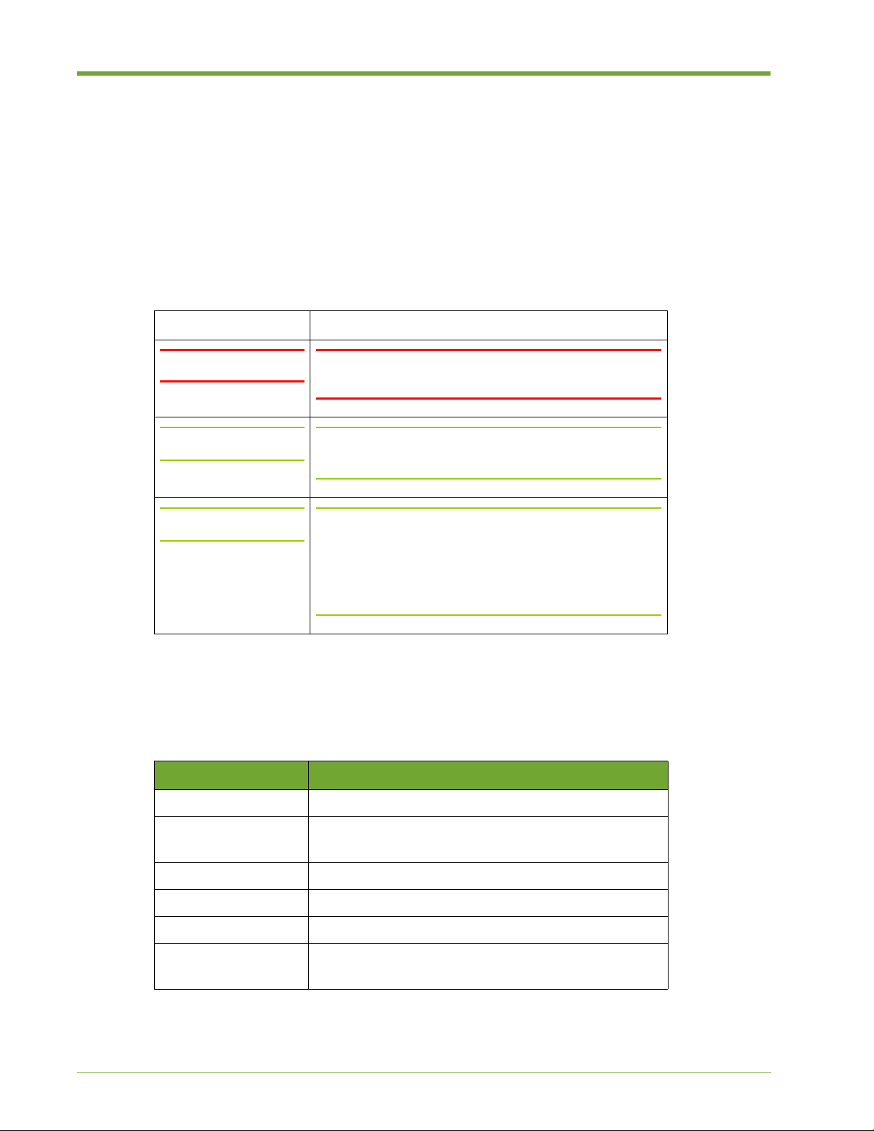
Icon Sample Text
WARNING! WARNING! Only authorized, qualified, and trained personnel
Caution: Caution: Follow the listed safety precautions when
should attempt to work on this equipment.
working on the HP VMA Array.
Note: Note: Read through this entire chapter and plan your
installation according to your location before installing
the equipment. The following procedures and the order
in which they appear are general installation guidelines
only.
Typographical Conventions
The following typographic conventions are used in this guide:
Format Meaning
Bold User Interface text.
Italic Provides emphasis and identifies variables and
document titles.
Courier
Courier bold
<Courier italic>
Command names, examples, and output.
Input you must type exactly as shown .
Information for which you must supply a value.
[]
Optional command parameters are enclosed within
square brackets.
Typographical Conventions
8 HP VMA SAN Gateway Installation and Configuration Guide AM456-9025A
Page 9
Format Meaning
|
Separates a set of command choices from which only
one may be chosen.
{}
Required command parameters that must be specified
are enclosed within curly brackets.
Typographical Conventions (continued)
Reference Documents
In addition to this guide, the following Hewlett-Packard documents comprise the documentation
suite for the HP VMA Array. These guides are available for download from the HP VMA manual
site at http://hp.com/go/vma-docs
This document... Provides this information...
Release Notes Describes the new features, resolved issues, known
limitations and software upgrade instructions for the
current release.
HP VMA SAN Gateway User’s Guide. Provides instructions for managing, monitoring, and
maintaining the HP VMA Array.
HP VMA-series Memory Array Installation and Service
Guide
Reference Documents
Getting Help
Contacting HP
Before you contact HP
Be sure to have the following information available before you contact HP:
• Technical support registration number (if applicable).
• Product serial number
• Product model name and number
• Product identification number
• Applicable error message
• Add-on boards or hardware
Provides instructions for installing, configuring, and
servicing a HP VMA Array.
• Third-party hardware or software
• Operating system type and revision level.
AM456-9025A HP VMA SAN Gateway Installation and Configuration Guide 9
Page 10

HP contact information
For the name of the nearest HP authorized reseller:
• In the United States, see the HP US service locator webpage (http://welcome.hp.com/country/
us/en/wwcontact.html).
• In other locations, see the Contact HP worldwide (in English) webpage (http://
welcome.hp.com/country/us/en/contact_us.html).
For HP technical support:
• In the United States, for contact options see the Contact HP United States webpage (http://
welcome.hp.com/country/us/en/contact_us.html).
To contact HP by phone, call 1-800-HP-INVENT (1-800-474-6836). This service is available
24 hours a day, 7 days a week. For continuous quality improvement, calls may be recorded or
monitored.
If you have purchased a Care Pack (service upgrade), call 1-800-633-3600.
• In other locations, see the Contact HP worldwide (in English) webpage (http://
welcome.hp.com/country/us/en/contact_us.html).
Subscription Service
HP recommends that you register your product at the subscriber’s Choice for Business website
(http://www.hp.com/country/us/en/contact_us.html).
Comments & Questions
HP welcomes your feedback. To make comments and suggestions about product documentation,
send a message to docsfeedback@hp.com.
10 HP VMA SAN Gateway Installation and Configuration Guide AM456-9025A
Page 11

CHAPTER 1 HP VMA SAN Gateway Hardware Installation
This chapter covers the HP VMA SAN Gateway hardware deployment in the
following topics.
• System Specifications on page 10
• Planning a Configuration on page 10
System Specifications
Planning a Configuration
Review the system specifications as described in System Specifications on page 65
to create a deployment plan that meets the requirements for your site.
Use the information in the following sections to define the configuration best suited
for your site:
• Defining a Configuration on page 11
• System Configuration Examples on page 11
AM456-9025A HP VMA SAN Gateway Installation and Configuration Guide 11
Page 12

Defining a Configuration
By the time you are ready to install the HP VMA SAN Gateways, the type of configuration to be
implemented should have already been decided upon:
• Standalone
• Redundant Gateway pair for High Availability access
If this decision has not yet been reached, review the System Configuration Examples in this chapter
to define the configuration best suited for your site. Then review the and acquire the necessary
items.
Note: For high availability access using redundant gateway pair , follow the planning instructions in
the Configuring a Redundant Pair of VMA SAN Gateways process guide at http://hp.com/go/vmadocs before you begin the installation.
System Configuration Examples
This section provides an overview of standard configurations supported for VMA-series SAN
Gateway and HP VMA Array systems:
• Single HP VMA SAN Gateway with 1–2 HP VMA-series Memory Arrays, Non Redundant on
page 12
• Redundant Pair of VMA-series SAN Gateways with 1–2 HP VMA-series Memory Arrays,
Highly Available on page 12
12 HP VMA SAN Gateway Installation and Configuration Guide AM456-9025A
Page 13
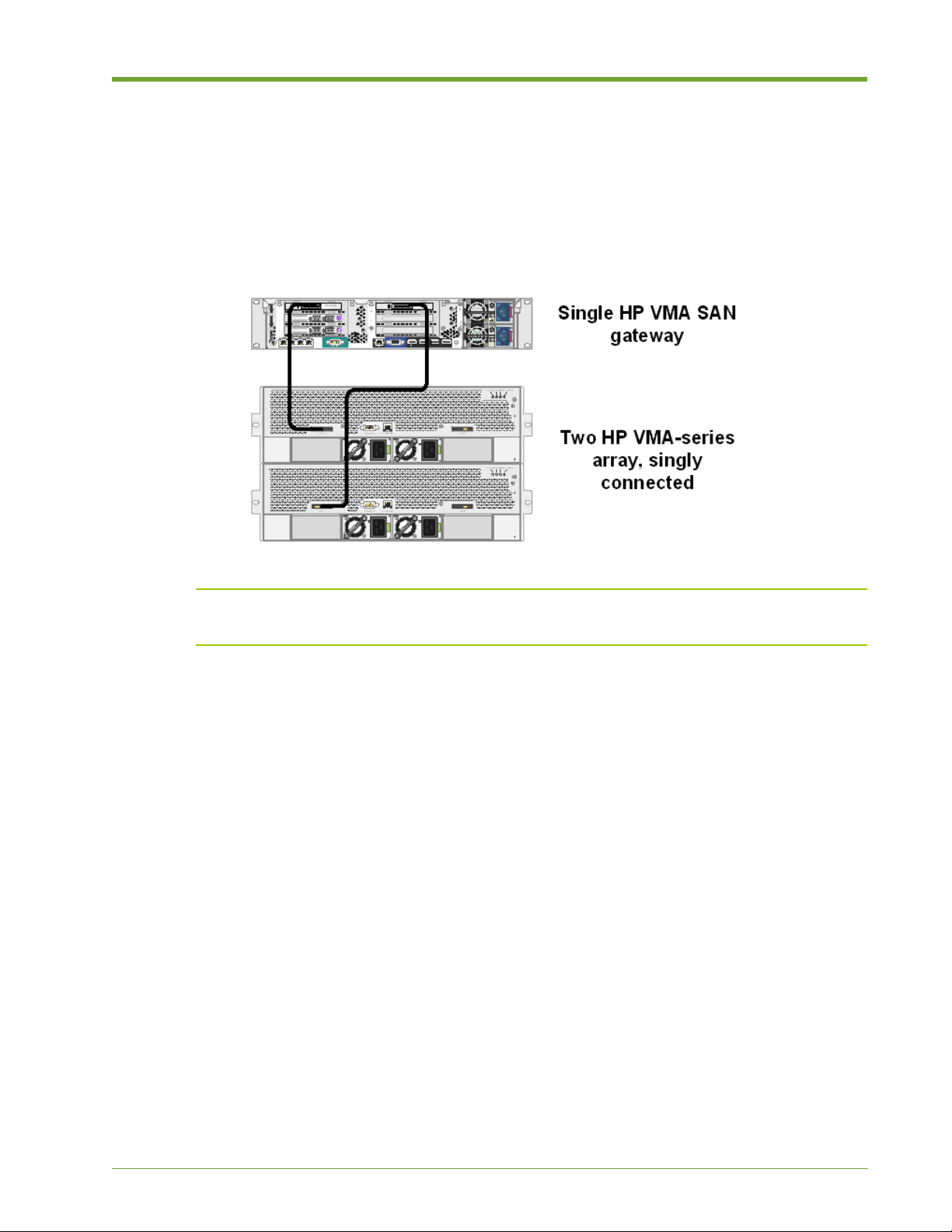
Single HP VMA SAN Gateway with 1–2
HP VMA-series Memory Arrays, Non Redundant
Figure 1.1 shows a configuration of a single VMA-series SAN Gateway is directly connected to a
group of up to two HP VMA-series Memory Arrays using PCIe cables. The HP VMA SAN
Gateway must be connected to Port 1 on each Memory Array in x8 mode.
Figure 1.1 Single HP VMA SAN Gateway with 2 HP VMA-series Memory Arrays, Non-Redundant
Note: In the vSHARE software, Port A refers to the port that is labeled Port 1 on HP VMA-series
Memory Arrays. Port B refers to the port that is labeled Port 2.
Redundant Pair of VMA-series SAN Gateways with 1–2
HP VMA-series Memory Arrays, Highly Available
Figure 1.2 shows the most common configuration, a High Availability (HA) pair of VMA-series
SAN Gateways that provide redundant access to a group of up to two HP VMA-series Memory
Arrays.
In the example, SAN Gateway 1 is connected to Port A on each Memory Array, and SAN Gateway
2 is connected to Port B on each Memory Array. It is important that the Memory Gateways are
cabled to the Memory Arrays using identical slots for HA pairs. That is, if PCIe Slot 1 on SAN
AM456-9025A HP VMA SAN Gateway Installation and Configuration Guide 13
Page 14
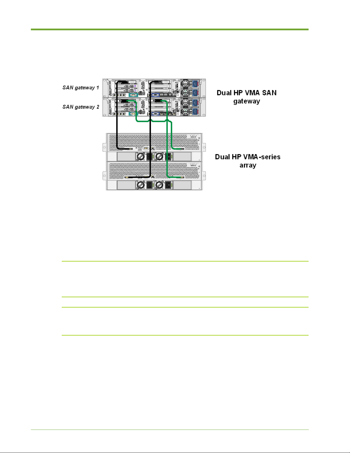
Gateway 1 is connected to Port A on Memory Array 1, then PCIe Slot 1 on SAN Gateway 2 must
be connected to Port B on Memory Array 1.
Figure 1.2 Redundant gateway pair of VMA-series SAN Gateways with 2 HP VMA-series Memory Arrays, Highly Available
The gigabit interfaces on each SAN Gateway, eth1 and eth2, are configured as a bonded interface
(where two interfaces act as one), eth0. HA configurations require that the management traffic and
cluster traffic both share the same physical links. A bonded network interface provides port/cable
redundancy . For more information, see the Configuring a Redundant Pair of VMA SAN Gateways
process guide at http://hp.com/go/vma-docs before you begin the installation.
Note: The Gateway Release Notes for Software OE G.5.5.1 has additional details for connecting the
HP VMA SAN Gateway with the HP VMA-series array. Also, configuration and turning
information per host operation system. Read these notes for this and other setup and configuration
information at http://hp.com/go/vma-docs.
Note: If you are planning to install and setup dual gateways as a redundant pair for High A vailability,
refer to the Configuring a Redundant Pair of VMA SAN Gateways process guide at http://hp.com/
go/vma-docs before you begin the installation.
14 HP VMA SAN Gateway Installation and Configuration Guide AM456-9025A
Page 15

AM456-9025A HP VMA SAN Gateway Installation and Configuration Guide 15
Page 16

16 HP VMA SAN Gateway Installation and Configuration Guide AM456-9025A
Page 17

CHAPTER 2 Software Setup and Configuration
This chapter covers the initial software setup for the HP VMA SAN Gateway, and
covers the following topics:
• Setup Task Map on page 15
• Requirements Checklist on page 16
• Defining the Configuration Type on page 18
• Configuring Nodes with the Setup Wizard on page 21
• Saving a Configuration on page 28
• Modifying an Existing Configuration on page 28
• Verifying vSHARE and Other Licenses on page 29
• Verifying Storage Media on page 30
Setup Task Map
HP VMA SAN Gateway software setup includes the following tasks:
Before You Begin:
Task 1:
Task 2:
Task 3:
Task 4:
AM456-9025A HP VMA SAN Gateway Installation and Configuration Guide 17
Fulfill the necessary prerequisites, as described in Requirements
Checklist
on page 16.
Defining the Configuration Type on page 18
Configuring Nodes with the Setup Wizard on page 21
Verifying vSHARE and Other Licenses on page 29
Verifying Storage Media on page 30
Page 18

Requirements Checklist
Before you begin the installation process, it is important that you have the necessary materials on
hand and have met the other requirements on the following checklist:
Requirement Notes
Laptop computer with terminal emulation
software
Appropriate serial cables for the Memory
Array and San Gateway
Network cable to attach between your
laptop and a node, if necessary
USB to serial converter to connect the serial
cable to your laptop
The appropriate SAN licenses, such as
vSHARE
Table 2.1 Configuration Checklist
PuTTY or similar emulation application
For more information, contact HP
Customer Support as described in Getting
Help on page 8
18 HP VMA SAN Gateway Installation and Configuration Guide AM456-9025A
Page 19

Gather the following information for each SAN Gateway node in preparation for the setup wizard.
Information Notes
Public Interface IP address
Public Interface Netmask
Global Default Gateway
DNS Server Names
(DNS server names in use at site)
Domain Name
(site domain name)
Hostname
(should have mg-a as part of the name)
Admin Password
Set Clock Time Zone
Zone to Use
(set a specific time zone, or pick UTC)
NTP Server Name
(IP address of the site’s NTP server)
Email Notification Recipients
(email addresses of people to receive VMA
Memory system support e-mails)
Email Mailhub
(IP address for the SMTP server, or
resolvable name for the site)
Email Mailhub Port
(typically 25, but verify for your site)
Enable HP Support?
Cluster Interface Name (for standalone
gateway , eth1. For redundant gateway, local
VLAN)
Cluster ID
(this name is preloaded)
Cluster Name
(choose a meaningful name)
Table 2.2 Software Configuration Checklist
AM456-9025A HP VMA SAN Gateway Installation and Configuration Guide 19
Page 20

Cluster Management IP Address
(VIP for MG cluster access for redundant
gateways.)
Cluster Management IP Netmask
Cluster Expected Nodes (Initially "1".
Change the value after following
instructions in the
Pairing Process Guide.
Table 2.2 Software Configuration Checklist
Defining the Configuration Type
Before you begin the configuration process, you should have defined a configuration type and be
familiar with its parameters.
• Standalone—Consists of one SAN Gateway with between one and two attached SAN
Gateways, as shown in the Single HP VMA SAN Gateway with 1–2 HP VMA-series Memory
Arrays, Non Redundant on page 12.
Information Notes
Redundant Gateway
)
Note: A standalone SAN Gateway is considered to be a single node cluster . For this reason, you
can configure the same parameters for a standalone SAN Gateway node as you would for the
master node in a several node cluster.
• High-A vailability (Redundant) Pair—Consists of two SAN Gateways, a designated master and
standby node, and one or two HP VMA-series Arrays, as shown in the Redundant Pair of
VMA-series SAN Gateways with 1–2 HP VMA-series Memory Arrays, Highly Available on
page 12. Additional SAN Gateway nodes are designated as normal nodes.
Note: The pairing of two HP VMA SAN Gateway nodes for a High Availability (HA) or redundant
configuration is achieved by following the Redundant Gateway Pairing Process documented in the
Redundant Gateway Pairing Process Guide.
Master and Standalone Node Parameters
The first HP VMA SAN Gateway added to a HP VMA SAN Gateway cluster becomes the master
node. A standalone SAN Gateway node is in effect a single master node cluster. For this reason, you
are prompted to answer the same configuration questions for a standalone node as you would for
the master node of a multi-node cluster. For an initial gateway bring-up, use the provided defaults
for cluster interface name, cluster id, cluster management IP, and netmask values.
The master node is the default gateway for all cluster management tasks, such as analyzing
performance for containers, LUNs, and targets; creating and exporting LUNs, or creating and
deleting initiator groups.
20 HP VMA SAN Gateway Installation and Configuration Guide AM456-9025A
Page 21

All global cluster parameters are defined on the master node, and are automatically inherited by
additional nodes as they are added to a cluster. The following chart lists the master or standalone
node parameters for which the configuration wizard prompts you.
Public interface name This specifies the Ethernet port that is used for specific gateway
management. If only a single Ethernet cable will be used to
connect the Gateway node, then eth1 should be used. If both eth1
and eth2 will be cabled to the network, then they should be bonded
as eth0, and eth0 should be used as the public interface. For more
information, see the
Redundant Gateway Pairing Process Guide.
Public interface IP address The public interface IP address for the individual gateway.
Note: DHCP is not recommended.
Public interface netmask The public interface netmask.
Global Default gateway The Default Gateway is set on a per-node basis.
DNS server name(s) Specify a primary and, optionally, a secondary DNS server.
DNS Domain name The name of your local domain.
Hostname A local hostname for the HP VMA SAN Gateway.
Admin password Setting a password is highly recommended.
Timezone Set the clock timezone by specifying the zone and subzones. (Use
"?" to display zone names interactively.)
NTP server Optional and recommended.
Email notification
recipients, mail hub, & port
Set recipients to
callhome-hp@vmem.com for HP Customer
Support and at least one email alias for your company, in a
comma-separated list.
Enable HP support Set autosupport to
yes to ensure proper handling of support
issues.
Cluster interface name The interface for internal vCLUSTER traffic. In a single Gateway,
this is eth1. A VLAN can be used instead with a redundant
gateway configuration to separate vCLUSTER multicast traffic
from management traffic. If using a VLAN, the cluster interface
name is based on the VLAN ID. For example, if you use VLAN
#14 then the cluster interface name is “vlan14”. In a dual-cabled
Gateway (in which both eth1 and eth2 are used) without a VLAN
being used, then the eth0 bonded interface should be specified for
the cluster interface name, refer to the
Process Guide
for profile configuration.
Redundant Gateway Pairing
AM456-9025A HP VMA SAN Gateway Installation and Configuration Guide 21
Page 22

Cluster expected nodes Set the number of nodes (HP VMA SAN Gateways) in the cluster
to "1". Change the value as in instructed in the
Pairing Process Guide
Note: This is the expected number of HP VMA SAN Gateway
.
Redundant Gateway
nodes only. Do not include the number of HP VMA-series Arrays.
Cluster ID The cluster id can be found in the login banner. The default is its
preset value. This id should be changed for redundant gateway
configurations.
Cluster name The name of the cluster used by the Domain Name System (DNS).
Cluster management
(virtual) IP address
The virtual IP address (VIP) for management of the cluster. The
virtual address is assigned to the master node of the cluster, and
redirected as needed whenever another node becomes the master
(used only for redundant gateway config).
Cluster management
(virtual) netmask
The virtual netmask for management of the cluster. The virtual
netmask is assigned to the master node of the cluster, and
redirected as needed whenever another node becomes the master
(used only for redundant gateway config).
Secondary Node Parameters
A secondary node in a cluster automatically inherits all the global cluster parameters from the
master node. Hence, there are fewer questions in the configuration wizard to answer for the standby
node.
The following table lists the configuration parameters for secondary nodes, along with a description
for each.
Public interface name This specifies the Ethernet port that is used for cluster
management. If only a single Ethernet cable will be used to
connect the SAN Gateway node, then eth1 should be used. If both
eth1 and eth2 will be cabled to the network, then they should be
bonded as eth0, and eth0 should be used as the public interface.
For more information, see the Redundant Gateway Pairing
Process guide.
Public interface IP address The public interface IP address.
Note: DHCP is not recommended.
Public interface netmask The public interface netmask for the individual gateway.
Default gateway The Default Gateway is set on a per/node basis. When a node is
part of a cluster, the Global Default Gateway takes precedence.
The Default Gateway is recommended for access to a cluster from
outside of the local network of a node.
22 HP VMA SAN Gateway Installation and Configuration Guide AM456-9025A
Page 23

Global default gateway Enable or disable. The Global Default Gateway is set and used for
the cluster. It is recommended that you enable the global default
gateway.
DNS server name(s) Specify a primary and, optionally, a secondary DNS server.
DNS Domain name The name of your local domain.
Hostname A local hostname for the HP VMA SAN Gateway.
Admin password Setting a password is highly recommended.
Timezone Set the clock timezone by specifying the zone and subzones. (Use
"?" to display zone names interactively.)
NTP server Optional and recommended.
Email notification
recipients, mail hub, & port
Set recipients to
Support and at least one email alias for your company, in a
comma-separated list.
Enable VMA support Set autosupport to
issues.
Configuring Nodes with the Setup Wizard
This section demonstrates how to use the setup wizard to configure every HP VMA SAN Gateway
in a cluster, and covers the following topics:
• Prerequisite on page 21
• Logging in to the SAN Gateway on page 22
• How to Get Help During the Configuration on page 23
• Configuring a HP VMA SAN Gateway Master/Standalone Node on page 23
• Configuring a Secondary HP VMA SAN Gateway Node on page 27
Caution: If you are planning a High A vailability (HA) redundant pair installation, follow the requirements and
procedures described in the Redundant Gateway Pairing Process guide at http://www.hp.com/go/vma-docs.
callhome-hp@vmem.com for VMA Customer
yes to ensure proper handling of support
Prerequisite
When you connect to the public interface, you are automatically prompted to log in.
Note: The admin user does not have a default password.
AM456-9025A HP VMA SAN Gateway Installation and Configuration Guide 23
Page 24
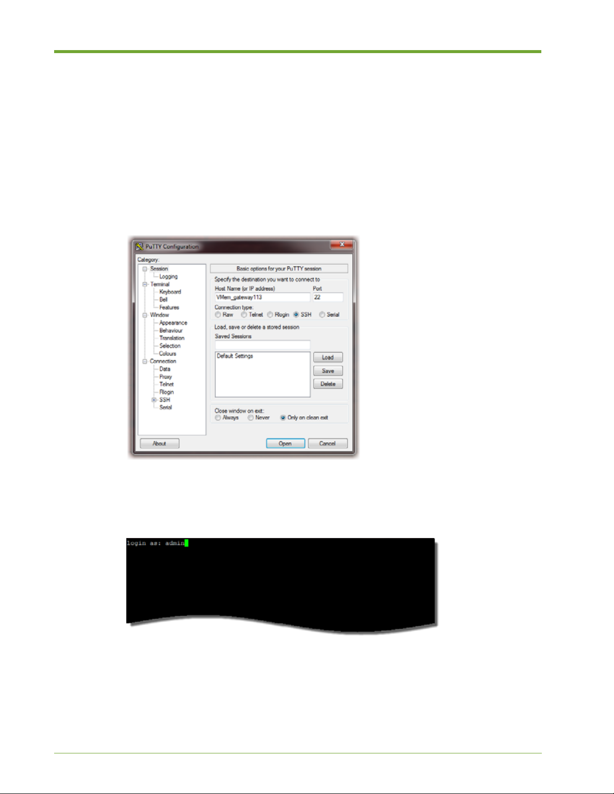
Logging in to the SAN Gateway
The configuration process is done through a locally connected KVM setup or a terminal emulator
window (such as PuTTY) connection to the SAN Gateway node.
To log in to the SAN Gateway node, do the following:
1. Launch a terminal window , enter the host name or IP address of the SAN Gateway node in the
appropriate text field, and open.
The following example shows a PuTTY launch dialog.
A terminal window appears, or use a KVM setup locally connected to the gateway.
2. Log in as admin.
The configuration wizard prompts you for an initial configuration of the HP VMA SAN
Gateway.
3. Review How to Get Help During the Configuration on page 23, then proceed with Configuring
a HP VMA SAN Gateway Master/Standalone Node on page 23.
24 HP VMA SAN Gateway Installation and Configuration Guide AM456-9025A
Page 25

How to Get Help During the Configuration
The configuration displays information on how to get help at the beginning of the wizard script, as
shown in the following example:
Violin Memory Gateway configuration wizard
Press '?' for help, Ctrl+B to go back to the previous step.
Default value is in square brackets: press Enter to accept it.
Press Ctrl+R to clear default to enter empty string.
Press Ctrl+C to jump to the end of the wizard at any time.
To get help with the current step in the wizard, enter "?". For example, for help with the timezone
type "?" to view the possible values:
...
Step 10: Set clock timezone? [yes]
Step 11: Zone to use? [UTC] America
Step 12: Sub-zone 1 to use? [Caribbean] ?
Caribbean Central North South
Press '?' for help, Ctrl+B to go back to the previous step.
Default value is in square brackets: press Enter to accept it.
Press Ctrl+R to clear default to enter empty string.
Step 12: Sub-zone 1 to use? [Caribbean] North
Step 13: Sub-zone 2 to use? [Canada] United_States
Step 14: Sub-zone 3 to use? [Alaska] ?
Alaska Arizona Central Eastern Hawaii Mountain Other Pacific
Press '?' for help, Ctrl+B to go back to the previous step.
Default value is in square brackets: press Enter to accept it.
Press Ctrl+R to clear default to enter empty string.
Step 14: Sub-zone 3 to use? [Alaska] Pacific
Step 15. NTP server name(s)? [0.0.0.0] 10.1.1.2
...
Configuring a HP VMA SAN Gateway Master/Standalone Node
The configuration wizard interactively configures the cluster settings, prompting you at each step
to enter a value or accept the default (or the current setting, if previously configured). After the last
step, the wizard repeats your settings and lets you return to any step if you want to make more
changes.
AM456-9025A HP VMA SAN Gateway Installation and Configuration Guide 25
Page 26

The fastest way to configure a master or standalone HP VMA SAN Gateway node is with the setup
configuration wizard.
Note: Interface bonding and cluster VLAN configuration are not included in the configuration
wizard setup. For initial cluster setup, or for single-Ethernet cable to Gateway configurations, you
can specify the eth1 interface as the “Public interface name” and “Cluster interface name” in the
wizard. Then configuration of the interface bonding and VLAN using the CLI will be done in the
Redundant Gateway Pairing Process Guide.
To configure the master or standalone SAN Gateway node, do the following:
1. Log in to the SAN Gateway as admin, as described in Logging in to the SAN Gateway on page
22.
2. The configuration wizard prompts you for an init ial configuration of the HP VMA SAN
Gateway. Enter Yes (the first letter must be capitalized).
Do you want to use the wizard for initial configuration? Yes
You are prompted to answer a series of configuration questions. The responses given for each
question will configure the initial HP VMA SAN Gateway, which becomes the master node.
3. After the first question, enter Yes.
Step 1: Configure as master/stand-alone? [yes]
Entering Yes defines the current HP VMA SAN Gateway as the master node, whether for a
single node cluster (standalone) or a redundant gateway pair. For information on configuring a
redundant gateway pair , see the
Redundant Gateway Pairing Process Guide at http://www .hp.com/
go/vma-docs.
26 HP VMA SAN Gateway Installation and Configuration Guide AM456-9025A
Page 27

4. Enter a value or press the Enter key to accept the default value shown in square brackets (if
one is present).
Step 2: Public interface name? [eth1]
Step 3: Public interface IP address? [10.1.14.200]
Step 4: Public interface netmask? [255.255.252.0]
Step 5: Global default gateway? [10.1.12.1]
Step 6: DNS server name(s)? [10.1.12.5]
Step 7: Domain name? [my.storageco.int]
Step 8: Hostname? [my-gateway1]
Step 9: Set clock timezone? [yes]
Step 10: Zone to use? [America]
Step 11: Sub-zone 1 to use? [North]
Step 12: Sub-zone 2 to use? [United_States]
Step 13: Sub-zone 3 to use? [Pacific]
Step 14: NTP server name(s)? [10.1.1.5,10.1.12.5]
Step 15: Email Notification recipient(s)? [admin@mystorageco.com]
Step 16: Email mailhub? [10.1.6.20]
Step 17: Email mailhub port? [25]
Step 18: Enable Violin support? [yes]
Step 19: Admin password (Enter to leave unchanged)?
Step 20: Cluster interface name? [eth1]
Step 21: Cluster expected nodes? [1]
Step 22: Cluster id? [99999-9999-1107]
Step 23: Cluster name? [gateway-cluster1]
Step 24: Cluster mgmt IP address and masklen? [0.0.0.0]
Note: VLAN and interface bonding configuration as used for configuration of a redundant
gateway pair is not part of the configuration wizard must be configured using the CLI. For
information on how to set up bonding and configure a VLAN, see the
Process Guide
5. After you complete the questions, the configuration wizard displays your responses and
.
Redundant Gateway Pairing
prompts you to press Enter to accept and save the settings:
To change an answer, enter the step number to return to.
Otherwise hit <enter> to save changes and exit.
Choice: █
AM456-9025A HP VMA SAN Gateway Installation and Configuration Guide 27
Page 28

The configuration wizard displays the HP VMA SAN Gateway cluster settings, as shown in the
following example, then exits to the CLI.
You have entered the following information:
1. Configure as master/stand-alone: yes
2. Public interface name: eth1
3. Public interface IP address: 10.1.14.200
4. Public interface netmask: 255.255.252.0
5. Global default gateway: 10.1.12.1
6. DNS server name(s): 10.1.12.5
7. Domain name: my.storageco.int
8. Hostname: my-gateway1
9. Set clock timezone: yes
10. Zone to use: America
11. Sub-zone 1 to use: North
12. Sub-zone 2 to use: United_States
13. Sub-zone 3 to use: Pacific
14. NTP server name(s): 10.1.1.5,10.1.12.5
15. Email Notification recipient(s): admin@mystorageco.com
16. Email mailhub: 10.1.6.20
17. Email mailhub port: 25
18. Enable Violin support: yes
19. Admin password (Enter to leave unchanged): (unchanged)
20. Cluster interface name: eth1
21. Cluster expected nodes: 1
22. Cluster id: 99999-9999-1107
23. Cluster name: gateway-cluster1
24. Cluster mgmt IP address and masklen: 0.0.0.0
To change an answer, enter the step number to return to.
Otherwise hit <enter> to save changes and exit.
Choice: █
Configuration changes saved.
6. To return to the configuration wizard after exiting, enter the command configuration
jump-start
Caution: The configuration jump-start command should only be used during the initial
installation of a specific gateway.
28 HP VMA SAN Gateway Installation and Configuration Guide AM456-9025A
in the CLI.
Page 29

Configuring a Secondary HP VMA SAN Gateway Node
Configuring a secondary SAN Gateway node is similar to configuring an additional node in a SAN
Gateway cluster (a standby or normal node).
Note: If you are configuring an additional node in a cluster , you should have successfully completed
the procedure described in Configuring a HP VMA SAN Gateway Master/Standalone Node on page
23.
• Standby node: The second node added to the cluster is automatically designated as the
secondary node. Should the master node fail, the secondary node replaces it and becomes the
master node and cluster management traffic is automatically redirected to the new master
node.
All global cluster parameters defined on the master node are automatically inherited by the
secondary node added to the redundant pair. Consequently, the configuration of the secondary
node requires only seven steps as compared to the 25 steps required to configure the master
node.
• Normal nodes: Each additional SAN Gateway added to the cluster is defined as a normal node.
During the course of vCLUSTER operation, a normal node can assume the role of standby or
master. There is always only a single master and at most a single standby node.
Prerequisite
You will need the following information:
• Public interface name—public interface name defined for the secondary node
• Public interface IP address—public interface IP address for this Secondary Gateway
• Public interface netmask—netmask for the public interface IP address
• Hostname—hostname for this secondary Gateway
• Cluster interface name—the interface name configured on the master node
• Cluster ID—cluster ID is pre-configured with HP VMA SAN gateway and should not be
changed at this time.
Configuring a Node
To configure a HP VMA SAN Gateway node as a redundant pair, refer to the Redundant Gateway Pair-
ing Process Guide at http://www.hp.com/go/vma-docs
AM456-9025A HP VMA SAN Gateway Installation and Configuration Guide 29
Page 30
Saving a Configuration
Y ou can save configuration parameters to persistent storage in the active configuration file from the
CLI using the configuration write command, as shown in the following example.
gateway02 [cluster1: master] (config) # configuration write
Note: It is recommended that you save the current configuration before making any modifications to
the configuration. This provides a backup configuration file, in case you want to revert to previous
settings.
Modifying an Existing Configuration
After the initial configuration parameters are set, you can modify and manage the configuration
through the Web Interface or the command line interface (CLI).
Note: The VMA Gateway Web Interface provides a subset of the commands available in the CLI.
However, it is recommended that you use the VMA Gateway Web Interface for ease of use.
Supported Web Browsers
This section provides information on the VMA Gateway W eb Interface requirements for browsers,
display resolution, Adobe Flash Player, JavaScript, and cookies.
The following table lists the supported browsers and versions for the VMA Gateway Web Interface.
Operating System Supported Browsers
Linux Mozilla Firefox 4 and above
Google Chrome 11 and above
Windows Windows Internet Explorer 9 and above
Mozilla Firefox 4 and above
Google Chrome 11 and above
Table 2.3 Supported Web Browsers
Note: For Windows Internet Explorer, Compatibility Mode should be turned OFF.
30 HP VMA SAN Gateway Installation and Configuration Guide AM456-9025A
Page 31

The following table lists the recommended software and settings for optimum performance of the
VMA Gateway Web Interface.
Recommendation Description
Display resolution The minimum recommended display resolution for the
VMA Web Interface is 1024 by 768 pixels.
JavaScript JavaScript must be enabled for the VMA Gateway Web
Interface.
Adobe Flash Player Adobe Flash Player version 8 (or above) is required for
viewing charts in the VMA Gateway Web Interface.
Cookies Enable cookies for login and session management. Cookies
are also used to store dashboard page settings.
Table 2.4 Recommended for the VMA Gateway Web Interface
Accessing the VMA Gateway Web Interface
You must use a supported browser with JavaScript and cookies enabled, as described in Supported
Web Browsers on page 28.
To access the VMA Gateway Web Interface, do the following:
1. Open a (supported) browser window.
2. Enter the following URL in the address field, substituting the variable in <brackets> with the
actual value for your system.
http://<Gateway_IP_address_or_hostname>
The log in page appears.
3. Log in as admin user.
For more information, see the HP VMA SAN Gateway User’s Guide.
Verifying vSHARE and Other Licenses
This section demonstrates how to verify that vSHARE and other installed licenses are active on the
HP VMA SAN Gateway.
To verify the vSHARE and other installed licenses, do the following:
1. Log in to the master node as admin and enter enable mode.
login as: admin
{cluster: master} > enable
#
AM456-9025A HP VMA SAN Gateway Installation and Configuration Guide 31
Page 32

2. Enter the following command.
# show license
Output similar to the following appears:
License 1: LK2-VSHARE-XXXX-XXXX-XXXX-XXXX-XXXX-XXXX
Feature: VSHARE
Valid: yes
Tied to cluster ID: 99999 (ok)
Active: yes
License 2: LK2-RESTRICTED_CMDS-XXXX-XXXX-XXXX-XXXX-XXXX-XXXX
Feature: RESTRICTED_CMDS
Valid: yes
Tied to cluster ID: 99999 (ok)
Active: yes
Note: If an installed license shows "no" as the Active output, an error may have been made when
inputting the license key. Double-check the valid license key against the key that is shown in the
show license output.
Verifying Storage Media
This section demonstrates how to verify the devices that are used by the SAN Gateway. For more
information, see the "Command Line Interface Reference" appendix of the
Guide
.
To verify the devices used by the SAN Gateway, do the following:
1. Log in to the master node as admin and enter enable mode.
login as: admin
{cluster master} > enable
#
2. Enter the following command.
# show media
All media devices are shown that can be used by the current VMA Memory Gateway (node or
module) as block storage or caching media. A summary line for each device location is sh own,
giving the size and status of that device. Media used by the system for other purposes are not
shown.
SAN Gateway User’s
32 HP VMA SAN Gateway Installation and Configuration Guide AM456-9025A
Page 33

CHAPTER 3 VMA SAN Gateway Management and
Configuration
This chapter covers VMA SAN Gateway configuration and management tasks and
includes the following topics:
• VMA SAN Gateway Management Overview on page 31
• Prerequisites on page 32
• Configuring Interface Bonding on page 32
• Gateway Network Configuration Guidelines on page 36
• Managing a Redundant Gateway Pair on page 37
VMA SAN Gateway Management Overview
Y ou can group together redundant HP VMA SAN Gateway pairs and connected HP
VMA-series Array nodes into a management group to create a virtual system that
can be managed and monitored as a single unit. A SAN Gateway management
group consists of one or two HP VMA SAN Gateway nodes, designated as follows:
• Master node: The first node added to a cluster becomes the active master
node. For more information, see Configuring a HP VMA SAN Gateway
Master/Standalone Node on page 23.
Note: A standalone SAN Gateway is a single node cluster, configured as a
master node.
• Secondary node: The second node in a cluster becomes the secondary node.
Should the master node fail, the secondary node automatically becomes the
master node through which management traffic is redirected. For more
information, see Configuring a Secondary HP VMA SAN Gateway Node on
page 27.
AM456-9025A HP VMA SAN Gateway Installation and Configuration Guide 33
Page 34

Note: At any one time, there can only be one active master node and one standby node in a cluster.
Prerequisites
You should have already successfully completed the following tasks.
• Configured the master HP VMA SAN Gateway node, defining the global cluster parameters in
the process.
• Set up HP VMA-series Memory Array nodes, as described in the
Installation and Service Guide
• Configured a secondary HP VMA SAN Gateway, taking on the global cluster parameters of
the master VMA SAN Gateway node.
For more information on these topics, see CHAPTER 2, “
page 15.
Configuring Interface Bonding
To form a management cluster, the Gigabit interfaces on each Gateway (eth1 and eth2) must be
configured as the bonded interface eth0.
Note: Redundant gateway pair configurations require that the management traffic and cluster traffic
both share the same physical links. You can configure a bonded network interface to provide port/
cable redundancy. For more information, see CHAPTER 4, “
page 49.
Interface bonding is the bundling of several physical ports together to form a single logical channel.
One bonding method is Link Aggregation Control Protocol (LACP), which can be used to allow
network devices to negotiate the automatic bundling of links with other devices that implement
LACP.
HP VMA-series Memory Array
.
Software Setup and Configuration” on
High Availability Configuration” on
Guidelines for Interface Bonding
When implementing interface bonding, follow these guidelines:
• Bond one or more network interfaces together using the
For interface bonding, eth0 is defined as a bonded interface consisting of two or more network
interfaces. All bonded interfaces share the same subnet. The Integrated Lights Out (iLO)
management port cannot be configured for general gateway management tasks. For more
information on interface bonding see HP VMA SAN Gateway User’s Guide.
34 HP VMA SAN Gateway Installation and Configuration Guide AM456-9025A
network bond command.
Page 35

• When using LACP, ensure that all network switches are LACP-enabled.
Depending on the switch’s capabilities and configuration, the port LACP settings may be either
active or passive. Active mode is recommended, because only aggregated traffic is expected
from the HP VMA SAN Gateway. For more information, see the HP VMA SAN Gateway User’ s
Guide.
Interface Bonding Example
There are many types of bonding modes available, some of which require changing network switch
settings. See the HP VMA SAN Gateway User’s Guide for more information on these modes.
The following example demonstrates how to configure a round-robin balance mode for a bonded
interface that does not require any switch changes. This creates a round-robin bond (eth0), that
effectively combines the eth1 and eth2 interfaces with eth0 virtual IP address (VIP).
To configure a round-robin balance mode interface bond, do the following:
1. Launch a terminal window, enter the host name or IP address of the master SAN Gateway
node in the appropriate text field, and open.
The following screenshot is an example of a PuTTY launch dialog.
A terminal window appears.
AM456-9025A HP VMA SAN Gateway Installation and Configuration Guide 35
Page 36

2. Log in as admin.
3. Enter enable mode, and then configure terminal with the following commands.
> enable
# configure terminal
4. Enable bonding using the following commands:
(config) # network bond eth0 interface eth1 interface eth2 mode balance-rr
(config) # cluster interface eth0
(config) # cluster master interface eth0
(config) # wr mem
5. Repeat steps 1 through 4 on the secondary node.
6. Reboot both HP VMA SAN Gateway nodes to reconnect the cluster.
VLAN Cluster Interface
You can hide the cluster multicast traffic using a VLAN for the cluster interface. This requires
changing network settings on your network switch. For information on how to set this up, see the
administration guide for your network switch.
36 HP VMA SAN Gateway Installation and Configuration Guide AM456-9025A
Page 37

Gateway Management Network Configuration
You must configure network switches and network connections for the cluster nodes, so that the
master and secondary nodes in a management group can communicate with each other.
Configuring Network Switches
Setting up and defining the network switches for the HP VMA SAN Gateway management group
includes the following tasks:
• Defining Initial IP Addressing on page 35
• Defining Additional Parameters on page 36
• Defining Cluster Name and Node Names on page 36
Before you Begin
Gather the following information for each node in a HP VMA SAN Gateway cluster:
• IP addresses
• Public interface IP address
• Netmask
• Cluster management virtual IP (VIP) address
• HP VMA-series Array IP address
Defining Initial IP Addressing
The following IP address assignments must be performed via serial console or direct connected to
the network switches of the HP VMA SAN Gateway:
• Public Interface Name and IP Address: For each node, define the public interface name, IP
address, and an associated netmask for the system’s private address requirements. (DHCP can
be used for these addresses; however, most installations use static IP addresses.)
• Cluster Management VIP: Define the cluster management virtual IP address. The cluster
management VIP directs all cluster management traffic to the public interface on the master
node.
• HP VMA-series Array IP Address: Define the Memory Array network management IP
address.
AM456-9025A HP VMA SAN Gateway Installation and Configuration Guide 37
Page 38

Defining Additional Parameters
Set the following parameters via the serial console port on the Master SAN Gateway, or via the
management VIP address:
• Global network parameters: Default Gateway or DNS Server information.
• NTP Server IP address for time synchronization.
• SMTP Server IP address for email configuration.
• Private VLAN for communication between redundant gateway pairs.
Defining Cluster Name and Node Names
Set the cluster name and the name for each HP VMA SAN Gateway node via the serial console port
on the Master Gateway, or via the cluster management VIP address:
• Define the cluster name to identify the VMA-series SAN Gateway redundant pair.
• Define the names for each HP VMA SAN Gateway in the pair. Typically, these would be given
obvious names such as “vmg-n1” and “vmg-n2” or something similar.
Configuring Network Connections
The next step is to configure support on the network switches for bonded interfaces and VLANs, as
described in the following topics:
• Gateway Network Configuration Guidelines on page 36
• Management VLAN Configuration on page 37
Gateway Network Configuration Guidelines
For illustrated examples of correct gateway cabling, see System Configuration Examples on page
11.
• Use single Ethernet to eth1 for each Gateway node. Set the cluster interface and the cluster
master interface (mgmt) to eth1.
• Connect eth1 and eth2, and then bond as eth0. Cluster interface and cluster master interface
(mgmt) are then set to eth0.
• Connect eth1 and eth2, and then bond as eth0. Configure the management interface for VLAN
on eth0 bond and the cluster master interface (mgmt) set to eth0.
Note: For a redundant configuration, the management and cluster interfaces should be bonded to a
single interface, eth0. That interface then becomes the management and cluster interface. For more
information, see CHAPTER 4, “High Availability Configuration” on page 49.
38 HP VMA SAN Gateway Installation and Configuration Guide AM456-9025A
Page 39

Management VLAN Configuration
The VMA-series SAN Gateway can use a separate network for low-latency, low-bandwidth
communication between HP VMA SAN Gateways in a cluster.
T o separate redundant gateway network traffic from management traffic, you can configure a virtual
local area network (VLAN). Network switches must also be configured to provide a private VLAN
if it will be used for the cluster network traffic.
For best performance and minimal impact on the customer network, HP recommends configuring
a private network for use by the cluster through VLAN tagging.
When VLANs span multiple switches, VLAN Tagging is highly recommended. A VLAN creates
an independent logical network within a physical network. VLAN Tagging is the process of
inserting a VLAN ID into a packet header in order to identify which VLAN the packet belongs to.
Each network switch port connected to a HP VMA SAN Gateway should be configured to allow
VLAN-tagged traffic for the given management VLAN ID. This is a configurable option that you
can change to suit your network setup. For more information on VLAN commands, see the HP
VMA SAN Gateway User’s Guide.
Some switch vendors, including Cisco, do not allow untagged traffic over an LACP link. If you are
using this type of switch, you must provide the HP VMA SAN Gateway with the public-facing
VLAN (in addition to the cluster VLAN) and tag the ports appropriately.
Note: Multicast DNS (mDNS) is used for cluster communication, and so must be allowed on all
switches. Use the IP multicast group address (224.0.0.251).
Managing a Redundant Gateway Pair
Management of a redundant gateway pair includes monitoring the HP VMA SAN Gateway nod es,
stopping or rebooting nodes, and upgrading the software running on the nodes. For information on
how to manage gateway nodes, see the
For information on upgrading SAN Gateway nodes, see CHAPTER 5, “
Upgrades”
Caution: Be sure to check the current Release Notes for the latest recommendations before beginning a
gateway software upgrade.
on page 75.
HP VMA SAN Gateway User’s Guide.
Memory Gateway Software
AM456-9025A HP VMA SAN Gateway Installation and Configuration Guide 39
Page 40

Configuration File Management
Changes made to the configuration of a HP VMA SAN Gateway redundant pair take effect
immediately. Those changes can be lost if they are not saved to a configuration file, however. The
HP VMA SAN Gateway redundant pair stores one or more configuration files on persistent storage,
one of which is designated as the active configuration file.
The active configuration file is where configuration changes are stored when you save a
configuration. Whenever the gateway reboots, it loads the configuration settings from the file
designated as active. The gateway backs up the active configuration file automatically.
For more information on managing configuration files, see the
HP VMA SAN Gateway User’s Guide.
User Roles
User management privileges are set by assigning one of the following roles to a user account:
• admin: The administrator role has full privileges to view anything, take any action, or change
any configuration. This role can access every page in the VMA Gateway Web interface.
• monitor: The monitor role can read all data and perform some actions, such as rebooting the
system and configuring various system parameters, but cannot change the configuration of the
VMA-series SAN Gateway. This role can view some of the pages in the Web interface.
Caution: Initially these accounts have no password. Setting a password for the admin role is highly
recommended.
The CLI command modes
monitor roles. For more information on managing users using the CLI and VMA Gateway Web
interfaces, see the HP VMA SAN Gateway User’s Guide.
configure, enable, and standard correspond to the admin and
Upgrading the Gateway Software
Part of managing a gateway is keeping the software version up to date. Upgrading the HP VMA
SAN Gateway software requires that you obtain the latest software release, run a command to
distribute and install the software on each HP VMA SAN Gateway, and then reboot the cluster.
40 HP VMA SAN Gateway Installation and Configuration Guide AM456-9025A
Page 41

CHAPTER 4 VMA Gateway Node Replacement
This chapter demonstrates how to replace a HP VMA SAN Gateway node in a
redundant pair, and covers the following topics:
• Prerequisites on page 39
• Procedure Steps on page 40
• Completing the Replacement on page 41
Prerequisites
A typical VMA gateway configuration consists of one or two HP VMA SAN
Gateways, one of which is designated as the master node (mg-b) and one which is
designated as the secondary node (mg-a). For more information on HP VMA Array
redundant pairs, see the
This following naming conventions apply in the replacement procedure:
• mg-a is the node that is being replaced in a redundant gateway pair
• mg-b is the active master node of the redundant gateway pair
HP VMA SAN Installation and User’s Guide.
AM456-9025A HP VMA SAN Gateway Installation and Configuration Guide 41
Page 42

Gather the following information before you begin the procedure to replace the gateway node (mga):
• Existing cluster ID (for the master node mg-b)
• Static IP address for master node mg-b
• Static IP address for node mg-a being replaced
• Netmask for node mg-a being replaced
Procedure Steps
Use this procedure to power down and remove a VMA Gateway node from a redundant gateway,
then configure a replacement VMA Gateway node.
Note: When a new factory shipped VMA Gateway node is first powered on, the configuration values
are set to the system defaults. You have to change the default settings to add the node to the
redundant pair.
To replace a Memory Gatew ay node in a redundant pair, do the following:
1. Connect and log in to the mg-a VMA Gateway node to be replaced as admin.
2. Shut down the node using the following command:
mg-a [violin: standby]# reload halt
3. Unplug and remove the failed Gateway node being replaced.
4. Rack and cable the replacement Gateway node. For more information, see the HP VMA SAN
Gateway Installation and User’s Guide
5. Power up the replacement Memory Gateway, log in as admin, and follow the steps as
described in "Using the Wizard to Configure the Master Node" in the
Installation and User ’s Guide
6. Accept the configuration options and exit the wizard. Then, watch for the state displayed on
.
.
HP VMA SAN Gateway
the command line prompt to ensure that it changes to "master".
7. Verify the version of software running on the newly replaced Memory Gateway (mg-a), using
the following command:
mg-a [violin: master]# show version
8. Proceed to Completing the Replacement on page 41.
42 HP VMA SAN Gateway Installation and Configuration Guide AM456-9025A
Page 43

Completing the Replacement
Go to the section that represents your configuration, and follow the steps to complete the
replacement:
• Both Nodes Running G5.1.0 on page 41
• G5.1.0 on mg-b and G5.2.0 or Higher on mg-a on page 41
• Both Nodes Running G5.2.0 or Higher on page 41
Both Nodes Running G5.1.0
If both your existing Memory Gateway node (mg-b) and the newly replaced Gateway node are both
running software version G5.1.0, complete the following steps:
1. While logged in to the newly replaced Memory Gateway node, enter the following command:
mg-a [violin: master]# cluster id <same_id_as_mg-b>
2. Watch the command line to ensure that the prompt changes to standby.
G5.1.0 on mg-b and G5.2.0 or Higher on mg-a
If your existing Memory Gateway node (mg-b) is running software version G5.1.0 and the newly
replaced Gateway node is running G5.2.0 or higher, contact HP Customer Support.
Both Nodes Running G5.2.0 or Higher
If both your existing Memory Gateway node (mg-b) and the newly replaced Gateway node are both
running software version G5.2.0, complete the following steps:
1. While logged in to the newly replaced Memory Gateway node, enter the following command at the
prompt:
mg-a [violin: master]# no cluster enable
2. Next, enter this command after the prompt:
mg-a [violin: master]# fms enable
The prompt changes to look like the following:
mg-a [FRU: searching](config)#
AM456-9025A HP VMA SAN Gateway Installation and Configuration Guide 43
Page 44

3. Log in to mg-b as admin, and enter the following command after the prompt:
mg-b [violin: master]# fms admit
The following is an example of the resulting output. The exact values will depend on your
configuration.
Found 1 FRU Module(s) applying for cluster membership:
1) Module ID: 1ededc96b4c6, Internal Address
169.254.181.61
Please make a selection from the above list to admit it
to the cluster.
4. Enter the number of the node you want to admit into the cluster. In this example, the c hoice is
1.
Your Choice? [1] 1
You selected module 1 for admittance.
5. You can choose to use DHCP, or enter static IP information. This example uses static IP
information.
Use DHCP? [yes] no
Please enter a routable IP address for this module.
Address? 10.1.10.140
6. Enter a valid netmask for the replacement node.
Please enter a valid netmask for this module.
Netmask? 255.255.252.0
You selected module 1 for admittance with IP address
10.1.10.140/22; module status has been successfully
updated.
Note: the new module can take several minutes to join the
cluster as it may need to upgrade itself before joining.
mg-b [violin: master] #
7. Go to the mg-a (newly replaced) node, and verify one of the following scenarios:
• If mg-a and mg-b nodes are running the same version of the software:
a. The prompt changes to violin-mga [FRU: join _pending] (config)
b. Th e mg -a nod e reboots.
c. The state displayed on the command line prompt changes to "standby".
• If mg-a and mg-b nodes are running different versions of the software:
a. The prompt changes to violin-mga [FRU: manufacturing] (config)
b. The mg-a node is updated with the same image (software version)
mg-b is running. This can take several minutes to complete.
c. The mg-a node reboots.
44 HP VMA SAN Gateway Installation and Configuration Guide AM456-9025A
Page 45

d. The state displayed on the command line prompt changes to "standby".
8. Go to mg-b and execute the following command at the prompt:
mg-b [violin: master]# cluster expected-nodes
<#_in_cluster>
AM456-9025A HP VMA SAN Gateway Installation and Configuration Guide 45
Page 46

46 HP VMA SAN Gateway Installation and Configuration Guide AM456-9025A
Page 47

CHAPTER 5 Block Storage Configuration
This chapter describes vSHARE, its features and functions, and the steps required
to configure the HP VMA SAN Gateway to manage block storage. The following
topics are covered:
• Understanding vSHARE on page 44
• Configuring Storage Containers on page 47
• Configuring Target Ports on page 49
• Configuring Initiator Groups on page 51
• Creating LUNs on page 53
• Exporting LUNs on page 56
Understanding vSHARE
vSHARE runs as software on a HP VMA SAN Gateway enabling host systems (for
example, database servers) to use the Fibre Channel transport protocols to access
logical units of data (LUNs) stored within HP VMA-series Arrays.
On the host system, the LUN appears as a connected SCSI disk. The host formats
and partitions the LUN. The storage system sees the contents of a LUN as a set of
blocks of arbitrary data. Administrators may use vSHARE to define rules for
controlling access to LUNs based on the containers, initiators and initiator groups,
and target ports configured within the system.
• Storage Containers: An HP VMA-series Array comprises a storage
container. Every LUN created and managed by vSHARE is created within a
storage container. You can create many LUNs within a container. However,
currently there is a one-to-one (1:1) mapping between an array and a container
(one container per array).
AM456-9025A HP VMA SAN Gateway Installation and Configuration Guide 47
Page 48

• Initiators and Initiator groups: An initiator is a host or client that requires access to the
LUNs stored in the containers. Multiple initiators may be grouped together in an initiator
group (igroup). Access to the LUNs in a container may be restricted to specific initiators or
initiator groups.
• Targets: A target identifies the port on the HP VMA SAN Gateway through which the
initiator may access the LUNs stored in a container . Access to the LUNs in a container may be
restricted by target port.
vSHARE System Architecture
The vSHARE architecture is ideal for applications that require rapid access to and processing of
large amounts of data including enterprise databases, data warehouses and application servers.
A typical VMA configuration cluster consists of one or two HP VMA SAN Gateways running the
vSHARE software application and one or more HP VMA-series Arrays.
Figure 5.1 vSHARE System Architecture
The vSHARE application runs on HP VMA SAN Gateways and allows you to manage LUN and
initiator-target relationships. The HP VMA SAN Gateways operate as the SAN targets and the hosts
(such as a database server or application server) are the
initiators.
The HP VMA SAN Gateway provides network connectivity, utilizing Fibre Channel protocol s. The
HP VMA SAN Gateway provides high performance processing, high bandwidth DRAM, and high
bandwidth access to the HP VMA-series Arrays. All LUNs created and managed by vSHARE. are
stored in containers, each container comprises a HP VMA-series Array that utilizes flash memory
storage.
For maximum performance, Single Level Cell (SLC) flash is used. For capacity to support readcentric applications, Multiple Level Cell (MLC) should be used. The HP VMA SAN Gateways and
HP VMA-series Arrays are connected via PCIe.
48 HP VMA SAN Gateway Installation and Configuration Guide AM456-9025A
Page 49

Configuration Overview
Configuring vSHARE is a prerequisite to using a HP VMA SAN Gateway for block storage. The
vSHARE configuration allows you to define sophisticated rules for controlling access to the LUNs
by initiator groups, initiators, or target ports.
Configuring target ports and initiator groups are optional steps in the vSHARE configuration
process. Organizations that do not want to use LUN-masking can control access to LUNs through
ports or switches. LUN masking is an authorization process used to make a logical unit number
available to some hosts and unavailable to others.
To configure vSHARE, complete the following procedures:
1. Configuring Storage Containers on page 47. This step initializes the HP VMA-series Array to
manage block storage and create one or more storage containers (partitions) to manage the LUNs. To
format the HP VMA-series Array from vSHARE, the media init command is required. This
command enables you to initialize one or more Memory Arrays to support block storage. Once a
Memory Array has been initialized to support block storage, you may create one or more storage
containers on each Memory Array, which may be used to store and manage LUNs.
2. (Optional) Configuring Target Ports on page 49. This step configures the target ports so they
can control access to LUNs. Configuring target ports is useful for security and bandwidth
management.
3. (Optional) Configuring Initiator Groups on page 51. This step configures the initiator groups,
adding one or more initiators to each initiator group. You can restrict access to LUNs by
initiator group, or on a per-initiator basis.
4. Creating LUNs on page 53.
LUNs are created within a storage container that comprises a particular HP VMA-series Array.
A LUN inherits the attributes of the container (HP VMA-series Array) in which it is created.
Note: As of this release, one container comprises a HP VMA-series Array.
5. Exporting LUNs on page 56. This required step exports the LUNs to the initiator groups or
initiators via target ports. Only those initiator groups or initiators to which the LUN is
exported may access the LUN. Access may be further restricted to a specific target port.
AM456-9025A HP VMA SAN Gateway Installation and Configuration Guide 49
Page 50

Configuring Storage Containers
The first step in configuring a vSHARE HP VMA SAN Gateway is to format the HP VMA-series
Arrays and create the containers needed to manage LUNs in the target storage on each Memory
Array . LUNs are addressable subsets of the container in a Memory Array. When a LUN is created,
it is assigned to a specific container and inherits the attributes of that container.
Note: As of this release, one container comprises a HP VMA-series Array.
Initializing HP VMA-series Arrays
To configure a HP VMA-series Array to support block storage, first initialize the HP VMA-series
Array using the
Command Syntax and Parameters
media init command.
This section describes the
media init command syntax and available parameters.
Syntax
media init device <VIOLIN_MEMORY_ARRAY_xxxxxxxxxxxxxx> type [block]
[force][name]
WARNING! Using the force option of the media init command (media init <device_name>
<block_name> force) destroys the existing data on a Memory array. You should not use this command
on a previously initialized Memory Array without first backing up the data on the Memory Array.
Parameters
device <device>
type
name
The <device> parameter indicates the Memory Array to be
initialized and is a string of the form:
VIOLIN_MEMORY_ARRAY_xxxxxxxxxxxxxx
ata-
The type parameter defines media, such as block (vSHARE).
The name parameter is used to name the partition. The default is to
use the last 14 characters of the HP VMA-series Array serial number.
To use a different name, add this parameter followed by a custom
name of up to 14 alphanumeric characters in length.
force
The force parameter is used to force initialization of a HP VMAseries Array that has already been initialized.
50 HP VMA SAN Gateway Installation and Configuration Guide AM456-9025A
Page 51

Configuring Block Storage
This section demonstrates how to use the
media init command to initialize a HP VMA-series
Array connected to a VMA Gateway for block storage.
To initialize the HP VMA-series Array for block storage, complete the following steps:
1. Connect to the HP VMA SAN Gateway through a terminal port, such as PuTTY.
2. Enter Configure mode, using the following commands.
> enable
# configure terminal
(config) #
3. Enter the media init command to initialize the HP VMA-series Array.
(config) # media init device ata-VIOLIN_MEMORY_ARRAY_23108R00000043
type block
This example generated the container ID: 23108R00000043.
4. (Optional) Use the name parameter to create a more intuitive name for the container ID. In the
following example, the generated container ID is changed to FASTBOX1:
(config) # media init device ata-VIOLIN_MEMORY_ARRAY_23108R00000043
type block name FASTBOX1
5. Confirm that you want to initialize the HP VMA-series Array.
Really initialize ata-VIOLIN_MEMORY_ARRAY_FASTBOX1 (all data will be
lost)? [no] y
A message confirms that the HP VMA-series Array was successfully initialized.
media init completed successfully
SM076 [NJ-Lab-vSHARE00: standby] (config) #
Viewing Containers
Once you have initialized the HP VMA-series Array, you can see the container that was created.
This section covers how to use the
Before a block media device can be used for block storage, it must be enabled. In the following
steps, you use the
media block id <id> enable command to enable the device.
show containers command to view existing containers.
AM456-9025A HP VMA SAN Gateway Installation and Configuration Guide 51
Page 52

To view existing containers, complete the following steps:
1. Log in as an administrator to the VMA Gateway attached to Port 1 of the HP VMA-series
Array.
2. Use the configure terminal command to enter Configure mode.
# configure terminal
(config) #
3. Enter the media block id all enable command to enable all block containers.
(config) # media <tab>
(config) # media block id all enable
block parameter ensures that you enable vSHARE devices. The all parameter ensures
The
that every block container is enabled.
4. To view all the containers were created, enter the show containers command. Information
about the containers displays.
> enable
# show containers
Container LUNs Total Free Ports HostnameA HostnameB
Status
----------------------------------------------------------------------
C-2 150 199G 50176M A,B <hostname> <hostname> cluster
Configuring Target Ports
The second step in configuring a HP VMA SAN Gateway is to configure the target ports. The target
ports control access to a particular LUN, which may be useful for both security and bandwidth
management.
This section covers the following topics:
• Supported Target Ports on page 49
• Configuring Fibre Channel Target Ports on page 50
Supported Target Ports
In a vSHARE system, the HP VMA-series Arrays are the targets and the host system (for example,
one or more database servers or application servers) are the
storage target devices (LUNs) that the hosts access through the HP VMA SAN Gateway.
The VMA SAN Gateway supports Fibre Channel target ports.
initiators. The storage systems have
52 HP VMA SAN Gateway Installation and Configuration Guide AM456-9025A
Page 53

Every target is a specific port on a hardware Fibre Channel host bus adapter (HBA) installed in the
gateway.
For Fibre Channel, the target ports are present when the HP VMA SAN Gateway boots.
A LUN may be exported through multiple target ports. Active-active multipathing is supported.
Configuring Fibre Channel Target Ports
For Fibre Channel, the target ports are present when the HP VMA SAN Gateway boots, if the HBAs
are installed on the system.
To confirm that the vSHARE system can see the target ports prior to creating the initiator groups,
use the
ports.
show targets Command
The
various options.
show targets command. The show targets command enables you to view all target
show targets command lists all of the target ports and their addresses (wwn), filtered by
Syntax
show targets [node <cluster node id>] [hostname <hostname>]
[protocol fc] [id <target id>] [sessions] [detail]
AM456-9025A HP VMA SAN Gateway Installation and Configuration Guide 53
Page 54

Parameters
[node <cluster node id>]
[hostname <hostname>]
[protocol fc]
[id <target id>]
[sessions]
[detail]
Configuring Initiator Groups
The third step in configuring the VMA SAN Gateway is to configure the initiator groups (igroups),
which identify the initiators (hosts) that are allowed to access a LUN or set of LUNs.
Every initiator has a protocol-specific identifier. Fibre Channel initiators are identified by WorldWide Names (WWN). Fibre Channel initiators are fixed by the appropriate HBA port.
Initiator Group Configuration
To configure an initiator group, complete the following steps:
Displays targets on node ID.
Displays targets on hostname.
Displays targets using protocols.
Displays a specific target.
Displays targets including sessions.
Displays in detail.
1. From the CLI, use the enable command (to enter Enable mode), and then the configure
terminal
> enable
# configure terminal
(config) #
2. Use the igroup name command to create an initiator group, as shown in the following
example, replacing the
(config) # igroup create name <my_igroup>
3. Add one or more initiators to the igroup, using the igroup addto command. The
initiator_name must be a valid name, such as,
(config) # igroup addto name <my_igroup> initiators
wwn.21:00:00:1b:32:7a:18:65
command (to enter Configure mode).
<my_igroup> variable with the actual igroup name.
wwn.21:00:00:1b:32:7a:18:65. .
In the following example, two Fibre Channel initiators are added to the igroup. The
<my_igroup> variable is a place holder for the actual igroup name.
(config) # igroup addto name <my_igroup> initiators
wwn.21:00:00:1b:32:9a:18:65 wwn.21:01:00:1b:32:ba:18:65
54 HP VMA SAN Gateway Installation and Configuration Guide AM456-9025A
Page 55

Fibre Channel initiator identifiers (WWN) are fixed by the HBA port. If you want to restrict
LUN access to a particular initiator, you must get the appropriate the WWN from the Fibre
Channel HBAs on the client machine.
4. To verify that the initiators were added to the initiator group, return to the CLI and enter the
show igroups command.
(config) # exit
# show igroups
Initiator group: <my_igroup> #Initiators: 2
wwn.21:00:00:1b:32:9a:18:65
wwn.21:01:00:1b:32:ba:18:65
The
show igroups command shows all initiator groups, the number of initiators within each
group, and the WWN of those initiators.
igroup create Command
The
igroup create command creates an initiator group and, optionally, one or more Fibre
Channel initiators. Fibre Channel initiator identifiers (WWNs) are generated automatically by an
HBA.
Syntax
[no] igroup create name <name>
Syntax Description
name
The name is alphanumeric only.
Examples
The following examples demonstrate how the
igroup create command can be used to manage
initiator groups and initiators.
The following command creates an initiator group named FINANCE:
igroup create name FINANCE
The Cisco-style
no prefix may be used to delete initiator groups or initiators. In the following
example, the command deletes the igroup FINANCE.
no igroup create name FINANCE
AM456-9025A HP VMA SAN Gateway Installation and Configuration Guide 55
Page 56

igroup addto Command
The
igroup addto command adds one or more initiators to a group.
Syntax
[no] igroup addto <igroup_name> initiators [initiator_name …]
igroup_name
initiator_name
The following command adds three initiators to the initiator group named FINANCE:
igroup addto FINANCE initiators wwn.20:20:20:20:20:20:20:20
wwn.20:20:20:20:20:20:20:21 wwn.20:20:20:20:20:20:20:22
The following command removes the initiator wwn.20:20:20:20:20:20:20:20 from igroup
FINANCE and preserves the other two initiators (wwn.20:20:20:20:20:20:20:21
wwn.20:20:20:20:20:20:20:22).
no igroup addto FINANCE initiators wwn.20:20:20:20:20:20:20:20
Creating LUNs
The fourth step in configuring the vSHARE system is to create the LUNs. In vSHARE, LUNs are
addressable subsets of the flash memory within the container that comprises a HP VMA-series
Array. In many systems, a LUN may be referred to as a
The name is alphanumeric only.
The initiator_name must be prefixed with “wwn.”
volume or logical unit.
Note: As of this release, one container comprises a HP VMA-series Array.
On the host system (initiator), the LUN appears as a local SCSI disk. The host may further format
and partition the LUN. The target, or storage system, sees the contents of the LUN as a set of blocks
of arbitrary data.
Every LUN is created within a container, and each container comprises a HP VMA-series Array.
vSHARE implements LUNs at a minimum of 1 GB increments with the ability to configure up to
1024 LUNs per HP VMA SAN Gateway.
LUN Creation
To create a LUN, complete the following steps:
56 HP VMA SAN Gateway Installation and Configuration Guide AM456-9025A
Page 57

1. From the CLI, enter into Enable mode using the enable command and then Configure mode using the
configure terminal command.
> enable
# configure terminal
(config) #
2. All LUNs are created and managed within a container. To view the available containers, use
the show containers command.
> enable
# configure terminal
(config) # show containers
Check the size of the containers. LUNs are implemented in 1 GB increments; the size of the
container may restrict the number of LUNs that may be created.
3. Enter the lun create command to create LUNs within a container.
(config) # lun create container <container_name> name <LUN_name> size
equal quantity 20 nozero
The command creates 20 LUNs of equal size in the container. Use the
nozero option to ensure that
the data is not zeroed-out, which could take considerable time depending on the size of the
container.
T ypically, fewer than 40 LUNs would be created within a container; however, the creation of up to
1024 LUNs is supported per container.
lun create Command
The
lun create command enables you to create a LUN within a specified storage container
connected to the VMA SAN Gateway.
Syntax
[no] lun create container <container_name> name <LUN_name> size [<size GB>
| equal] [quantity <number>] [nozero] [readonly] [startnum <unsigned
integer>] [blksize 512 | 4096] [offline]
Syntax Description
The following table shows syntax for LUN commands.
name
Defines the name of LUN to be created; used as a prefix if the
quantity of LUNs created is greater than one.
AM456-9025A HP VMA SAN Gateway Installation and Configuration Guide 57
Page 58

size
Defines the size of each LUN in GB, or "equal" to divide the free
space of the container equally among the new LUNs. A value of
0 (zero) may be used in place of "equal."
container
quantity
nozero
readonly
startnum
blksize
offline
lun set Command
Identifies the name of the container in which the LUN is created.
Defines the number of LUNs to be created; the default is 1. If the
number is greater than 1, the names of the newly created LUNs
will be appended with an index number from
startnum up to the
number of LUNs created.
Specify to avoid zeroing-out the data on the LUNs, which could
take a long time for large LUNs.
Creates the LUNs in read-only mode.
Defines starting index number for newly created LUNs. The
default is 1.
Defines the logical block size for the created LUNs; the default is
512, and can be set to 512 or 4096. Not all systems can handle
4096-byte sizes. Use 512 if you are unsure.
Creates the LUNs in offline mode.
The
lun set command allows you to set the parameters of a LUN in a container . For example, you
can set the LUN as read-only, as well as enable and disable the export of a LUN through one or both
HP VMA SAN Gateways. For more information, see Disabling HA Mode for a LUN or Container
on page 58.
The
lun set command is the only command usable after a LUN has been created except the no
lun create … readonly
command.
Syntax
[no] lun set container <id> name <name> readonly
show luns Command
The
show luns command allows you to view various types of information about a LUN or LUNs.
Syntax
show luns [container] [name] [count] [reserved] [serial] [sessions]
58 HP VMA SAN Gateway Installation and Configuration Guide AM456-9025A
Page 59

Syntax Description
container Displays only the LUNs within a specific container.
name Displays a specific LUN.
count Displays LUNs with active sessions and their count.
reserved Displays LUNs with SCSI reservations.
serial Displays the serial numbers for each LUN.
sessions Displays the sessions accessing a particular LUN.
show containers Command
show containers command displays all available containers.
The
Syntax
show containers
Exporting LUNs
The fifth step in configuring the vSHARE HP VMA SAN Gateway is to export the LUNs to an
initiator. The LUN must be exported before it may be accessed over block protocols.
Note: vSHARE LUNs are defined and saved within the Arrays themselves. vSHARE LUN export
records are, however, managed and stored within the vCLUSTER configuration database owned by
the master node.
Access to LUNs may be restricted to a specific initiator group, initiator, or target port when the LUN
is exported using the
• The optional
lun export command.
[igroup | initiator] parameter identifies the initiator group or initiator
that may access the LUN.
• The optional
[port] parameter identifies the target that may access the LUN.
A LUN ID is a SCSI identifier which may be used to differentiate between devices on the same
target port. By default, vSHARE automatically assigns LUN IDs to LUNs when they are exported
to an initiator group or initiator.
vSHARE optionally enables you to assign a special, user -defined LUN ID to a vSHARE LUN when
you export LUNs to an initiator group or initiator. User-defined LUN IDs may make it easier
differentiate between LUNs. If you do assign user-defined LUN ID, it is recommended that you
specify a number below 255, as some operating systems (for example, Windows) will only discover
LUN IDs between 0 and 254. LUNs cannot be exported if they are assigned an existing LUN ID;
an error message is returned and the export fails.
AM456-9025A HP VMA SAN Gateway Installation and Configuration Guide 59
Page 60

lun export Command
The
lun export command enables you to export the LUNs within a specific container to an
initiator or initiator group. A single LUN may be exported multiple times through different target
ports (multipathing) or to different initiators (shared access).
Syntax
[no] lun export container <container_name> name <lun_name> [lunid][to
<igroup | initiator>]... [using <port …>]
Syntax Description
lun_name
The lun_name could be wildcard specified, such as
FINANCE*
container <container_ID>
name <lun_name>
lunid
Name of the container.
Name of the LUN.
Designates the LUN ID assigned to an exported LUN.
By default, LUN IDs are automatically assigned by
vSHARE. User-defined LUN IDs may be specified to
track specific LUNs.
igroup
The name of the igroup.
If no igroup or initiator is specified, all initiators will
have access to the LUN.
initiator
port
The WWN (Fibre Channel) name of the initiator.
The port is Fibre Channel wwn ID.
Optimizing Connectivity to Storage Arrays for Windows
Depending on the Windows operating system, client machines connected to the VMA SAN
Gateway should use the Microsoft® Multipath I/O (MPIO) driver for optimal storage array
connectivity. Install the appropriate driver for your operating system.
Windows Server 2008 R2 and Above
Install the Microsoft MPIO driver. MPIO is not installed by default. Use the following link for
installation instructions.
Installing and Configuring MPIO for Windows Server 2008 R2:
http://technet.microsoft.com/en-us/library/ee619752(WS.10).aspx
In HA configurations, you must ensure a proper MPIO operation when a HP VMA SAN Gateway
failure occurs.
60 HP VMA SAN Gateway Installation and Configuration Guide AM456-9025A
Page 61

To ensure a proper MPIO operation, complete the following steps:
1. Install SP1 on Windo ws Server 20 08 R2.
2. Install HotFix KB2522766 (from the Microsoft Support site).
3. Install HotFix KB2460971 (from the Microsoft Support site).
4. Install Hotfix KB2468345 (see the Microsoft Support site)
5. Install Hotfix KB2531907 (see the Microsoft Support site)
6. Install Hotfix KB2591462 (see the Microsoft Support site).
To change the load balance policy setting, complete the following steps:
1. Open the Registry Editor and navigate to:
[HKEY_LOCAL_MACHINE\SYSTEM\CurrentControlSet\Services\v1010dsm\Parame ters\DsmLoad
BalanceSettings\<EnumeratedViolin LUN>
2. Modify DWORD: DsmLoadBalancePolicy and change the value to 2 for all discovered LUNs.
3. Restart the client machine.
Disabling HA Mode for a LUN or Container
By default, LUNs are online via all available ports. LUNs are considered to be in HA mode when
they are online via both ports in the Array. If necessary, such as for debugging purposes, you can
explicitly take a LUN or a container out of HA mode, so that it is accessible via only one port.
For example, the following command removes the FINANCE LUN from HA mode by setting it
offline for Port B, and making it accessible only from Port A:
(config) # no lun set container Strad201 name FINANCE port B online
When the LUN has been taken out of HA mode, the
the LUN as
# show luns
Container: Strad201
LUN Size RW Bksz Status Ports
-------------------------------------------------------------------
FINANCE 10240M rw 512 Single A
Single and indicates the port from which it is online. For example:
show luns command displays the status of
The following command sets a container offline from Port B, making it accessible only from Port A:
(config) # no container set name Strad201 port B online
AM456-9025A HP VMA SAN Gateway Installation and Configuration Guide 61
Page 62

The show containers command indicates that the status of the container is Single and displays
the number and hostname of the Gateway for the online port. For example:
# show containers
Container LUNs Total Free Ports HostnameA HostnameB
Status
----------------------------------------------------------------------
--------
Strad201 1 10G 50G A MG-1 --- Single
62 HP VMA SAN Gateway Installation and Configuration Guide AM456-9025A
Page 63

CHAPTER 6 Multipath Client-Side Configuration
This chapter provides examples of client-side multipath setup for the HP VMA
SAN Gateway. The following topics are covered:
• Multipath Overview on page 60
• Multipath Setup on page 61
Note: The examples in this chapter are guidelines for (client-side) Red Hat
Enterprise Linux 5.x DM Multipath. For more information, go to the Red Hat W eb
site: http://docs.redhat.com/docs/en-US/Red_Hat_Enterprise_Linux/
Multipath Overview
Multipath I/O is commonly used when there is more than one physical path
between the system CPU and the storage devices. The redundant paths are
leveraged to increase performance and fault-tolerance.
Device Mapper Multipath (DM Multipath, Red Hat Enterprise Linux) is the
multipathing utility used in the example presented in this chapter . DM Multipath is
a generic framework that maps each physical path to a SCSI device represented as
a separate
of combining multiple such block devices into a single block device. DM Multipath
uses Device Mapper kernel framework for mapping IOs between individual paths
and user-space daemon
the mapped device.
To determine which devices (and paths) correspond to a particular LUN, DM
Multipath initiates a query. The response to the query returns the LUN serial
number (among other information). The serial number for a LUN remains the
AM456-9025A HP VMA SAN Gateway Installation and Configuration Guide 63
/dev entry in a form of a block device. DM Multipath provides means
multipathd for providing configuration and policy for
Page 64

same, regardless of the number of paths that are associated with the LUN. Using the LUN serial
number, DM Multipath can determine how many paths are associated with that particular LUN. The
mechanism for getting a serial number is controlled by
described in the next section.
Multipath Setup
This section covers setting up and configuring DM Multipath on the client side for use with HP
VMA SAN Gateway provided LUNs.
Prerequisites
Before you begin setting up DM Multipath, do the following:
1. Verify that the device-mapper-multipath rpm is installed, as shown in the following
example.
getuid_callout parameter, which is
[root@redhat123 ~]# rpm -qa | grep multipath
device-mapper-multipath-0.4.7-23.el5_3.1
Note: The name of the package and the version shown may vary depending on your Linux
distribution and version.
2. Make a copy of the original multipath.conf file. This ensures that you have the original
file as backup, should an unexpected problem arise.
cp multipath.conf multipath.conf.bak
Note: The multipath package includes a file showing the default values that you can also use as a
customization template, as well as a couple of other helpful files. Go to the
/usr/share/doc/device-mapper-multipath-0.4.7/ directory to access these files:
multipath.conf.defaults
•
• multipath.conf.annotated
• multipath.conf.synthetic
Also see the man page for details on the available multipath.conf options.
man multipath.conf
64 HP VMA SAN Gateway Installation and Configuration Guide AM456-9025A
Page 65

Setting Up DM Multipath
This section shows you how to edit the multipath.conf file (the configuration file for
multipathd) then configure the multipath daemon to start when the system boots up. DM
Multipath default settings are suitable for common multipath configurations.
Setting up DM Multipath includes the following tasks:
1. Editing the multipath.conf File on page 62
2. Configuring the Multipath Daemon on page 64
Editing the multipath.conf File
This section presents the recommended configuration file for
SAN Gateway.
To edit the multipath.conf file, do the following:
multipathd for use with a HP VMA
AM456-9025A HP VMA SAN Gateway Installation and Configuration Guide 65
Page 66

1. Edit the multipath.conf file, uncommenting entries, similar to the following example. The
devnode_blacklist includes devices for which you do not want multipathing enabled.
defaults {
polling_interval20
max_fds 8192
user_friendly_namesyes
}
blacklist_exceptions {
device {
vendor "VIOLIN"
product "SAN ARRAY"
}
}
blacklist {
device {
vendor "*"
product "*"
}
}
devices {
device {
vendor "VIOLIN"
product "SAN ARRAY"
path_grouping_policy group_by_serial
path_checker tur
# uncomment the corresponding getuid_callout for your OS
# Ubuntu getuid_callout
"/lib/udev/scsi_id -p 0x83 -g -u -s /block/%n"
# RHEL5/OL5 getuid_callout
"/sbin/scsi_id -p 0x80 -g -u -s /block/%n"
# RHEL6/OL6 getuid_callout
"/sbin/scsi_id --whitelisted --replace-whitespace --page=0x80 --device=/dev/
%n"
# SLES11 getuid_callout
"/lib/udev/scsi_id --page=0x83 --whitelisted --replace-whitespace --device=/
dev/%n"
path_selector "round-robin 0"
failback immediate
rr_weight uniform
no_path_retry 6
# For RHEL6.2 or other newer kernels (see man multipath.conf),
change to rr_min_io_rq
rr_min_io 4
fast_io_fail_tmo5
dev_loss_tmo 30
}
}
66 HP VMA SAN Gateway Installation and Configuration Guide AM456-9025A
Page 67

In the above example, support for Memory Array devices was added. When configuring this
file, pay particular attention to the following:
•
path_grouping_policy should be set to group_by_serial
• getuid_callout should be set
• path_checker should be tur(TEST_UNIT_READY)
• failback should be immediate
• rr_weight should be uniform since weights are not assigned to the individual paths
• no_path_retry should be set to immediately bring path back online
• rr_min_io should be set to 4, but can be subject to change depending on the environment and
workload.
2. Save the multipath.conf file and proceed with Configuring the Multipath Daemon.
Configuring the Multipath Daemon
This section demonstrates how to configure the multipath daemon (
multipathd) so that it starts
when the system boots up.
To configure the multipath daemon, do the following:
1. Use the chkconfig command to add (-a) the multipath daemon (multipathd) as a service.
2. Restart the multipath service, using the service restart command.
3. Verify that the multipath service is running, using the multipath -ll command.
The following example demonstrates these steps for a single LUN that is accessible through two
Fibre Channel (FC) ports that are multipathed into a single multipath device (
mpath1
# chkconfig -a multipathd
# service multipathd restart
# multipath -ll
mpath176 (36001b97074dc2dff74dc2dfe97c7089e) dm-0 VIOLIN, ARRAY
[size=1.0G][features=0][hwhandler=0][rw]
\_ round-robin 0 [prio=0][active]
\_ 5:0:2:1 sdl 8:176 [active][ready]
\_ 5:0:3:1 sdm 8:192 [active][ready]
mpath11 (36001b97074dc2dff74dc2dfeb6ecc00a) dm-1 VIOLIN, ARRAY
[size=1.0G][features=0][hwhandler=0][rw]
\_ round-robin 0 [prio=0][active]
\_ 5:0:2:2 sdx 65:112 [active][ready]
\_ 5:0:3:2 sdy 65:128 [active][ready]
).
/dev/mapper/
AM456-9025A HP VMA SAN Gateway Installation and Configuration Guide 67
Page 68

68 HP VMA SAN Gateway Installation and Configuration Guide AM456-9025A
Page 69

APPENDIX A System Specifications
This appendix contains the system specifications for the HP VMA Array and HP
VMA Array.
HP VMA SAN Gateway Specifications
Review the following table to plan for a deployment that meets the requirements of
your site.
3000 Series
Model
Violin Memory 3205
Violin Memory
3210
Flash Type SLC SLC
Raw Capacity
(GiB/GB)
VIMM Count
5.3TB/5.7TB 10.7TB/
11.5TB
40+2 40+2
(Data + Hot Spare)
Reliability /
Resiliency
System Level Hardware Based
vRAID
VIMM level Hot-Swap
Redundant power supply and
fans
Active/Active external memory
gateways
Connectivity Options 1x PCIe Gen1 x8, or 2x PCIe
Gen1 x4
With external memory gateways:
8x 8/4Gb/s Fibre Channel
8x 10GbE iSCSI
AM456-9025A HP VMA SAN Gateway Installation and Configuration Guide 69
Page 70

3000 Series
Model
3000 Array Enclosure
Dimensions:
Violin Memory 3205
Violin Memory
3210
Height:
Width:
Depth:
Cable Management:
Maximum Weight:
3000 Array Enclosure
Power
3000 Array Enclosure
Cooling
Memory Gateway
Dimensions:
Height:
Width:
Depth:
Maximum Weight:
Memory Gateway
Power
Client Operating
Systems Support
3RU
16.9" / 430mm
28.4" / 721mm
7" / 178mm
76lbs / 34.5kg
800W 800W
3860 BTU/hr 3860 BTU/hr
2RU
17.2" / 437mm
25.5" / 648mm
50lbs / 22.7kg
500W
PCIe: RHEL, SLES, Windows
With external memory gateways:
RHEL, SLES, Windows, HPUX
Management CLI: Serial, Telnet, SSH / SNMP
/ Web GUI / REST XML API /
iPad
70 HP VMA SAN Gateway Installation and Configuration Guide AM456-9025A
Page 71

3000 Series
Model
Violin Memory 3205
Violin Memory
3210
Environmentals Inlet Temp: 0C to 35C
Humidity: 5-95% (non
condensing)
Altitude: 10,000 feet (Derate
temperature)
Regulatory Safety: IEC/EN 60950, CB
Certificate, UL60950-1 CAN/
CSA-C22.2 No.60950-1, CE
Mark
Emissions Class A: EN55022/
CISPR 22, FCC Part 15 Class A,
ICES-003 Issue 4 Class A, VCCI
Class A, AS/NZS CISPR22:2006
Class A, BSMI CNS 13438 Class
A, Korea RRA Notice No. 201118 Class A
Immunity: EN55024, EN 610004-2,3,4,5,6,8,11, Korea RRA
Notice No. 2011-17
AM456-9025A HP VMA SAN Gateway Installation and Configuration Guide 71
Page 72

72 HP VMA SAN Gateway Installation and Configuration Guide AM456-9025A
Page 73

APPENDIX B Compliance Information
This appendix contains the following compliance information for the HP VMA
SAN Gateway.
• Security & Compliance on page 69
• Regulatory Model Number on page 70
• Advised General Precautions on page 70
• Installation Conditions and Precautions on page 70
• Electrostatic Discharge (ESD) Precautions on page 71
• Lithium Battery Caution on page 72
• Cabinet Safety Precautions on page 72
• Disposal of W aste Equipment by Users in Private Households in the European
Union on page 72
• Perchlorate Material - Special Handling May Apply on page 73
• European Union RFI Statement on page 73
• USA Radio Frequency Interference FCC Notice on page 73
• Japan Radio Frequency Interference VCCI on page 73
• Korea RFI Statement on page 73
• Canada RFI Statement on page 74
• Australia C-Tick Label on page 74
• Taiwan BSMI Statement on page 74
AM456-9025A HP VMA SAN Gateway Installation and Configuration Guide 73
Page 74
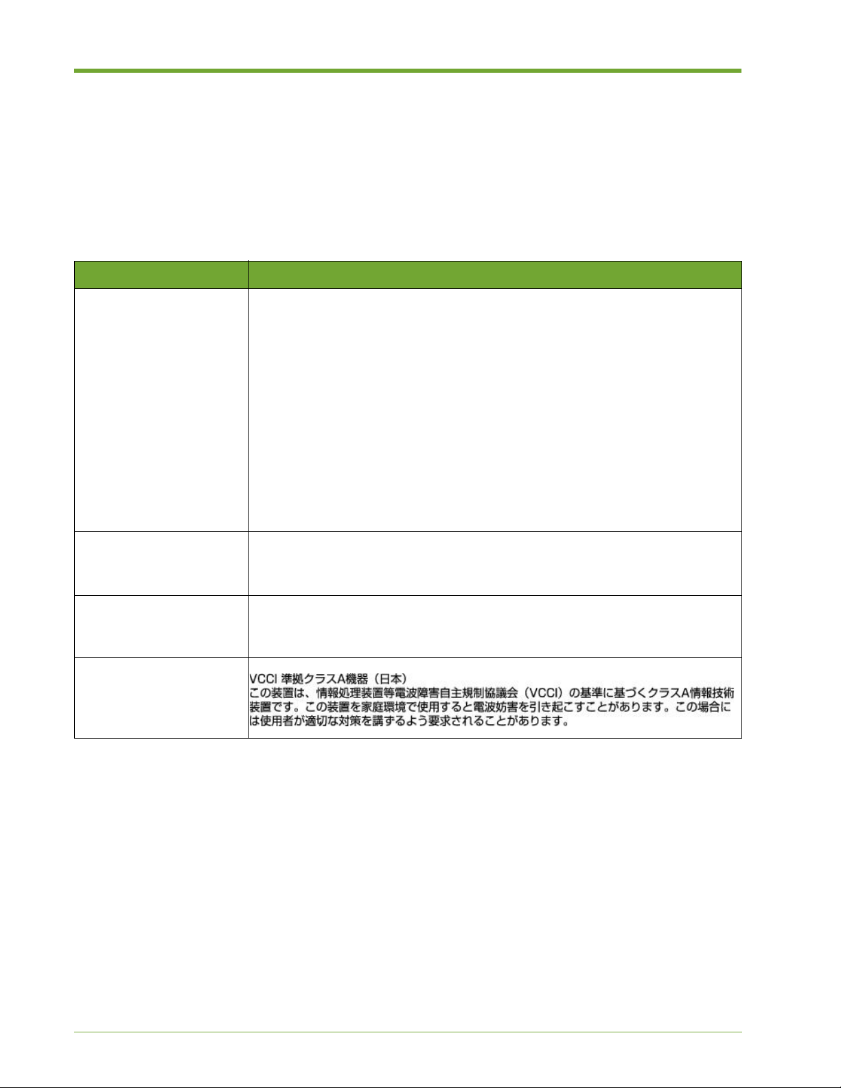
Security & Compliance
HP cannot be responsible for unauthorized use of equipment and will not make allowance or credit
for unauthorized use or access.
Compliance Information
Notice Description
FCC Class A
Compliance
"This device complies with Part 15 of the FCC Rules. Operation is subject to the
following two conditions: (1) This device may not cause harmful interference,
and (2) this device must accept any interference received, including interference
that may cause undesired operation."
This equipment has been tested and found to comply with the limits for a Class
A digital device, pursuant to Part 15 of the FCC Rules. These limits are
designed to provide reasonable protection against harmful interference when the
equipment is operated in a co mmer cial e nviro nmen t. This e qui pmen t genera tes,
uses, and can radiate radio frequency energy and, if not installed and used in
accordance with the instruction manual, may cause harmful interference to radio
communications. Operation of this equipment in a residential area is likely to
cause harmful interference, in which case, you are required to correct the
interference at your own expense.
Canada This class A digital apparatus complies with Canadian ICES-003.
Cet appareil numérique de la classe A est conforme à la norme NMB-003 du
Canada.
CISPR22 Warning: This is a class A product. In a domestic environment, this product
may cause radio interference, in which case, the user may be required to take
adequate remedial measures.
Japan
Table Preface.1 Compliance Information
74 HP VMA SAN Gateway Installation and Configuration Guide AM456-9025A
Page 75

Regulatory Information
For your protection, this product has been tested for conformance to various national and
international regulations and standards. The scope of this regulatory testing includes electrical and
mechanical safety, electromagnetic emissions, immunity, acoustics and hazardous materials.
Regulatory Model Number
For the purpose of regulatory compliance certifications and identification, this product is assigned
a regulatory model number. This number can be found on the product label, along with the required
approval markings and information. When requesting certification information for this product,
always refer to this regulatory model number.
Note: Do not confuse the regulatory model number with the marketing or model number.
Advised General Precautions
This section covers a list of highly recommended general precaution s:
• Keep the area around the installation clean and free of clutter.
• While working on the system, do not wear loose clothing such as neckties and unbuttoned shirt
sleeves, that can come in contact with electrical circuits or accidentally be pulled into a
cooling fan.
• Remove any jewelry or metal objects from your body before you begin working on a system.
Metal is an excellent conductor and these objects could create short circuits and cause bodily
harm.
Installation Conditions and Precautions
See the installation instructions for your system before connecting this equipment to the input
supply.
WARNING! The equipment must be provided with a proper AC protective earth (PE) ground connection.
• Know the locations of the power on/off switch on the chassis, as well as the emergency poweroff switch, disconnection switch, or electrical outlet in the room in which the system is
installed. Should an electrical accident occur, this ensures that you can quickly shut off the
power to the system.
• Do not work alone when performing procedures that involve high voltage components.
• Always disconnect the power to a system before removing or installing system components.
Before you disconnect the power, first power down the (operating) system and then unplug
power cords for all power supply modules.
AM456-9025A HP VMA SAN Gateway Installation and Configuration Guide 75
Page 76

• The power supply power chord must include a grounding pl ug and must be plugged into
grounded circuit outlets.
• Use only one hand when working with powered-on electrical equipment. This helps to avoid
creating a complete circuit, thus preventing electrical shock.
WARNING! There is a danger of explosion if the onboard battery is installed upside down, as a result of
reversed polarities. This battery must be replaced only with the same type of batter, or an equivalent type
recommended by the manufacturer.
• Be careful when handling batteries. Do not damage the battery in any way, as it may then
release hazardous materials into the environment. Comply with the regulations established by
your local hazardous waste management agency and dispose of used batteries in accordance
with their rules.
Network Connected Equipment
WARNING! The installation must provide a ground connection for the network equipment.
Electrostatic Discharge (ESD) Precautions
When handling any electronic component or assembly, you must observe the following antistatic
precautions to prevent damage. An ESD kit (P/N A3024-80004) is available (or supplied with
memory additions). This kit contains one wrist strap, one conductive sheet, and one antistatic foam
pad.
• Always disconnect power from the server and wear a grounded wrist strap when working
around the server.
• Always wear a grounded wrist strap when handling printed circuit boards.
• Keep all components in their antistatic bags until ready to use. Return components back inside
their antistatic bags when not in use.
• Touch a grounded metal object before removing a component from its antistatic bag.
• Do not let components come in contact with your clothing, which may retain a charge even if
you are wearing a wrist strap.
• Treat all assemblies, components and interface connections as static-sensitive.
• Do not use mats designed to decrease electrostatic discharge as a protection from electrical
shock. Instead, use rubber mats that have been specifically designed as electrical insulators.
• Avoid working in carpeted areas, and keep body movement to a minimum while removing or
installing boards, to minimize buildup of static charge.
• Use extreme caution when using metal tools, which can damage electrical components or
circuit boards they come in contact with.
76 HP VMA SAN Gateway Installation and Configuration Guide AM456-9025A
Page 77

Lithium Battery Caution
WARNING! Observe the correct polarity when changing the lithium battery. There is a danger of explosion if
battery is installed incorrectly.
Replace only with the same or equivalent type recommended by the manufacturer. Dispose of used batteries
according to the manufacturer’s instructions and local disposal requirements.
Note: Switzerland: Annex 4.10 of SR 814.013 applies to batteries.
Cabinet Safety Precautions
WARNING! Cabinets are heavy even when empty. Exercise caution when moving cabinets whether
equipment is installed in the cabinet or not. Av oid rolling cabinets on rough or uneven surfaces or inclines
greater than 10 degrees. Unloading cabinets from the pallet and movement of cabinets should be performed
by at least two people.
Slidable products are not to be extended from the cabinet while the equipment is on the shipping pallet. The
cabinet must be unloaded from the pallet and all anti-tip devices properly installed prior to extending any
slidable product.
Once installed, all anti-tip devices must remain in place to maintain stability. Only one slidable product must
be extended at a time.
Failure to follow these precautions can result in damage to equipment or injury to personnel.
Disposal of Waste Equipment by Users in Private Households in the European Union
This symbol on the product or on its packaging indicates that this product must not be
disposed of with your other household waste. Instead, it is your responsibility to dispose
of your waste equipment by handing it over to a designated collection point for the
recycling of waste electrical and electronic equipment.
The separate collection and recycling of your waste equipment at the time of disposal will help to
conserve natural resources and ensure that it is recycled in a manner that protects human health and
the environment. For more information about where you can drop off your waste equipment for
recycling, please contact your local city office, your household waste disposal service or the shop
where you purchased the product.
AM456-9025A HP VMA SAN Gateway Installation and Configuration Guide 77
Page 78

Perchlorate Material - Special Handling May Apply
See http://www.dtsc.ca.gov/hazardouswaste/perchlorate.
This product may include a real-time clock battery or coin cell battery that may contain perchlorate
and may require special handling when recycled or disposed of in California. Refer to the product
user documentation to determine if this product contains batteries, and if so, the battery type(s) that
are used.
European Union RFI Statement
This is a Class A product. In a domestic environment this product may cause radio interference in
which case the user may be required to take adequate measures.
USA Radio Frequency Interference FCC Notice
This equipment has been tested and found to comply with the limits for a Class A digital device,
pursuant to Part 15 of the FCC Rules. These limits are designed to provide reasonable protection
against harmful interference when the equipment is operated in a commercial environment.
This equipment generates, uses, and can radiate radio frequency energy and, if not installed and
used in accordance with the instruction manual, may cause harmful interference to radio
communications. Operation of this equipment in a residential area is likely to cause harmful
interference, in which case the user will be required to correct the interference at his own expense.
The user is cautioned that changes or modifications not expressly approved by HP
could result in the equipment being noncompliant with FCC Class A requirements and void the
user’s authority to operate the equipment.
Japan Radio Frequency Interference VCCI
Korea RFI Statement
78 HP VMA SAN Gateway Installation and Configuration Guide AM456-9025A
Page 79
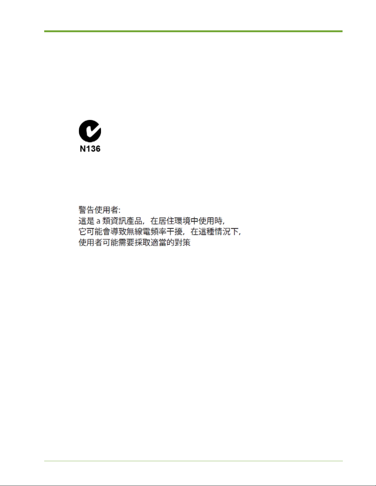
Canada RFI Statement
This Class A digital apparatus complies with Canadian ICES-003.
Cet appareil numérique de la classe A est conforme à la norme NMB-003 du Canada.
Australia C-Tick Label
Figure B.1 Australian C-Tick Label
Taiwan BSMI Statement
AM456-9025A HP VMA SAN Gateway Installation and Configuration Guide 79
Page 80

80 HP VMA SAN Gateway Installation and Configuration Guide AM456-9025A
Page 81

Index
A
admin role 38
access privileges 38
password, setting 38
B
battery, lithium 72
block size, of LUNs 55
block storage media devices
initializing Memory Arrays
block storage, configuring 48
BSMI statement, Taiwan 74
C
cabinet safety 72
caution icons 7
cluster
configuration guidelines
configure Gateway 27
expected nodes 20
ID 20
interface name 19
name 20
network switches 35
node replacement 39
nodes, adding 27, 29
cluster management
virtual IP address
virtual netmask 20
command modes
roles, correspondence to
compliance
information
20
69
36
38
47–48
security 69
Config mode
admin role 38
configuration files
38
active
management of 38
configuration wizard 28
additional Memory Gateways 27
Master Gateway configuration 32
containers
configuring 47
viewing 48
C-Tick label, Australia 74
customer support 8
D
default gateway 19, 20
device mapper (DM) 60
DM Multipath 61
DNS
domain name
server name 19, 21
19, 21
E
electrostatic discharge 71
Enable mode
monitor role
ESD 71
38
F
FCC notice, USA 73
AM456-9025A HP VMA SAN Gateway Installation and Configuration Guide 81
Page 82

Fibre Channel
network connectivity 36
target ports 50
G
global default gateway 21
H
HA mode
disable for container
disable for LUN 58
High Availability
disabling 58
I
igroup
addto 53
create 52
igroups
See initiator groups
initiator groups
configuration 51
configuration of 51–52
definition 45
interfaces
bonding of 33
public interface 19, 20
58
Memory Gateway
cluster configuration 35, 37
configure additional 27
configure cluster 27
system configurations 12
upgrade 38
monitor role 38
access privileges 38
monitor username
password 38
multipath
client side setup
configuration 62
daemon (multipathd) 64
daemon, configuring 64
device mapper 60
overview 60
setup 61
multipath.conf 61, 62
multipathd 62, 64
60
N
network connectivity 36–37
network switches
configuration of 35–36
node
31
master
normal node 27
NTP server 19, 21
P
L
LACP
interface bonding, and
lithium battery 72
lun
54
create
export 57
set 55
LUNs
creation of
exporting of 56–57
LUN IDs 56, 57
53–55
32
M
master node 31
parameters 18
mDNS 37
media init 47
Memory Arrays
initializing for block storage 47–48
82 HP VMA SAN Gateway Installation and Configuration Guide AM456-9025A
password
admin 38
monitor 38
perchlorate material, handling 73
public interface
IP address 19, 20
name 19, 20
netmask 19, 20
R
Redundant gateway pair of VMA-series SAN Gateways with
2 HP VMA-series Memory Arrays, Highly Available
Redundant Pair of VMA-series SAN Gateways with 1–2 HP
VMA-series Memory Arrays, Highly Available
regulatory
information
model number 70
replacement, node 39
RFI statement
Canada
European Union 73
70
74
13
12
Page 83

Korea 73
role
admin 38
monitor 38
roles
correspondence to command modes
roles, user 38
S
safety, cabinet 72
show containters 56
show luns 55
show targets 50
Standard mode
unpriv role
standby node 27
storage containers 47
38
T
target
definition 45
target ports
configuring
Fibre Channel ports 50
supported 49
timezone 19, 21
49
U
upgrade
Memory Gateway 38
user
management 38
privileges 38
admin role 38
38
monitor role 38
roles 38
setting password 38
user management 38
V
VCCI statement, Japan 73
vCLUSTER
configuration wizard
IP addressing 35
network configuration 35
VIPs
cluster management VIP
VLAN
cluster interface name, and 19
switches, configuration of 37
VLAN tagging 37
VLAN, cluster configuration 37
VMA Web Interface
supported web browsers 28
vSHARE
architecture 45
configuration 46
overview 44
23
35
W
warning icons 7
waste disposal, European Union 72
Windows
optimized connectivity
Server 2008 R2 57
57
Z
zeroing-out data 54, 55
AM456-9025A HP VMA SAN Gateway Installation and Configuration Guide 83
 Loading...