

Page 1

HP VMA-series Memory Array
Installation and Service Guide
Abstract
This document describes the installation and service procedures for the HP VMA-series Memory Array. This document
is intended for experienced service technicians. HP assumes that you are qualified in the servicing of computer
equipment, are trained in recognizing hazards in products with hazardous energy levels, and are familiar with
weight and stability precautions for rack installations.
Part Number: HP-AM456-9002A Rev 01
August 2011
Page 2

LEGAL NOTICES
© Copyright 2011 Hewlett-Packard Development Company, L.P.
The information contained herein is subject to change without notice. The only warranties for HP products and
services are set forth in the express warranty statements accompanying such products and services. Nothing herein
should be construed as constituting an additional warranty. HP shall not be liable for technical or editorial errors or
omissions contained herein.
Copyright © 2010-2011 Violin Memory, Inc. All rights reserved.
Violin Memory, Violin Technologies, Violin and Design, Violin, vSHARE, vCACHE, and Flash Forward are trademarks,
registered trademarks or service marks of Violin Memory, Inc. ("Violin") in the United States and other countries.
All other brands, product names, company names, trademarks, and service marks are the properties of their
respective owners.
This document and the associated software product are protected by copyright and international treaties, and are the
confidential and proprietary information and property of Violin, and are distributed only under license from Violin,
including confidentiality restrictions and other restrictions on use, copying, redistribution and reverse engineering.
Unless otherwise agreed by Violin in writing, Violin's standard end user license agreement shall apply, which may be
reviewed at www.violin-memory.com/legal. No part of this document may be reproduced, distributed, adapted or
translated without prior written permission of Violin, except as expressly permitted under the license from Violin. The
associated software product may include, access or otherwise operate, interface or be delivered with third party
software or other applications or copyrighted materials, which are copyrighted and licensed by Violin suppliers. Such
third party materials and licenses are identified in this document and/or at www.violin-memory.com/legal.
Violin assumes no responsibility for any typographical, technical or other error or omission in this document. Violin
reserves the right to periodically change the information contained in this document, but Violin makes no commitment
to provide any such changes, updates, enhancements or other additions in a timely manner or at all.
The only warranties for Violin software, hardware and other products and services are set forth in the express
warranty statements accompanying such products and services. Nothing herein should be construed as constituting
an additional warranty. THIS DOCUMENT (INCLUDING ANY EXAMPLES AND OTHER INFORMATION CONTAINED
HEREIN) IS MADE AVAILABLE "AS IS" WITHOUT REPRESENTATION OR WARRANTY OF ANY KIND. VIOLIN MAKES NO
REPRESENTATION OR WARRANTY IN THIS DOCUMENT REGARDING ANY ASSOCIATED SOFTWARE OR ANY OTHER
VIOLIN OR THIRD PARTY HARDWARE, SOFTWARE OR OTHER PRODUCTS OR SERVICES REFERENCED HEREIN. TO
THE FULLEST EXTENT PERMITTED BY LAW, VIOLIN (FOR ITSELF AND ITS LICENSORS AND OTHER THIRD PARTIES
IDENTIFIED HEREIN) HEREBY DISCLAIMS ALL REPRESENTATIONS AND WARRANTIES, WHETHER EXPRESS OR
IMPLIED, ORAL OR WRITTEN, WITH RESPECT TO THE FOREGOING, INCLUDING WITHOUT LIMITATION, ALL IMPLIED
WARRANTIES OF TITLE, NON-INFRINGEMENT, QUIET ENJOYMENT, ACCURACY, INTEGRATION, MERCHANTABILITY
OR FITNESS FOR ANY PARTICULAR PURPOSE.
IN NO EVENT SHALL VIOLIN (OR ITS LICENSORS OR ANY OTHER THIRD PARTY IDENTIFIED HEREIN) BE LIABLE
CONCERNING ANY USE OF THIS DOCUMENT, REGARDLESS OF THE FORM OF ANY CLAIM OR ACTION (WHETHER IN
CONTRACT, NEGLIGENCE, STRICT LIABILITY OR OTHERWISE), FOR ANY DIRECT, INDIRECT, PUNITIVE, INCIDENTAL,
RELIANCE, SPECIAL, EXEMPLARY OR CONSEQUENTIAL DAMAGES, INCLUDING WITHOUT LIMITATION, ANY LOSS OF
DATA, LOSS OR INTERRUPTION OF USE, COST OF PROCURING SUBSTITUTE TECHNOLOGIES, GOODS OR SERVICES,
OR LOSS OF BUSINESS, REVENUES, PROFITS OR GOODWILL, EVEN IF ADVISED OF THE POSSIBILITY OF SUCH
DAMAGES.
Violin Memory, Inc.
685 Clyd
e Avenue
Mountain View, CA 94043
USA
2
VMA-series Memory Array Installation and Service Guide
HP-AM456-9002A Rev 01
Page 3
COMPLIANCE INFORMATION
Notice Description
FCC Class A
Compliance
“This device complies with Part 15 of the FCC Rules. Operation is subject to the following
two conditions: (1) This device may not cause harmful interference, and (2) this device must
accept any interference received, including interference that may cause undesired
operation.”
This equipment has been tested and found to comply with the limits for a Class A digital
device, pursuant to Part 15 of the FCC Rules. These limits are designed to provide
reasonable protection against harmful interference when the equipment is operated in a
commercial environment. This equipment generates, uses, and can radiate radio frequency
energy and, if not installed and used in accordance with the instruction manual, may cause
harmful interference to radio communications. Operation of this equipment in a residential
area is likely to cause harmful interference, in which case, you are required to correct the
interference at your own expense.
Canada This class A digital apparatus complies with Canadian ICES-003.
Cet appareil numérique de la classe A est conforme à la norme NMB-003 du Canada.
CISPR22 Warning: This is a class A product. In a domestic environment, this product may cause
radio interference, in which case, the user may be required to take adequate remedial
measures.
Japan
HP-AM456-9002A Rev 01
VMA-series Memory Array Installation and Service Guide
3
Page 4

4
VMA-series Memory Array Installation and Service Guide
HP-AM456-9002A Rev 01
Page 5

Table of Contents
List of Figures . . . . . . . . . . . . . . . . . . . . . . . . . . . . . . . . . . . . . . . . . . 13
List of Tables . . . . . . . . . . . . . . . . . . . . . . . . . . . . . . . . . . . . . . . . . . . 15
Preface . . . . . . . . . . . . . . . . . . . . . . . . . . . . . . . . . . . . . . . . . . . . . . . 17
PART I. Product Overview
CHAPTER 1. VMA-series Overview . . . . . . . . . . . . . . . . . . . . . . . . . . . . . . .23
Features . . . . . . . . . . . . . . . . . . . . . . . . . . . . . . . . . . . . . . . . . . . . . . . . . . . . . . . . . . . . . . . . . . . . . . . . . . . . . . . . . . . . . . . . . . 24
Physical Components . . . . . . . . . . . . . . . . . . . . . . . . . . . . . . . . . . . . . . . . . . . . . . . . . . . . . . . . . . . . . . . . . . . . . . . . . . . . . .24
Chassis. . . . . . . . . . . . . . . . . . . . . . . . . . . . . . . . . . . . . . . . . . . . . . . . . . . . . . . . . . . . . . . . . . . . . . . . . . . . . . . . . . . . . . . . . . . . . . . . . . 24
System LEDs . . . . . . . . . . . . . . . . . . . . . . . . . . . . . . . . . . . . . . . . . . . . . . . . . . . . . . . . . . . . . . . . . . . . . . . . . . . . . . . . . . . . . . . . . . . . .25
Power Supplies. . . . . . . . . . . . . . . . . . . . . . . . . . . . . . . . . . . . . . . . . . . . . . . . . . . . . . . . . . . . . . . . . . . . . . . . . . . . . . . . . . . . . . . . . . .27
Fans. . . . . . . . . . . . . . . . . . . . . . . . . . . . . . . . . . . . . . . . . . . . . . . . . . . . . . . . . . . . . . . . . . . . . . . . . . . . . . . . . . . . . . . . . . . . . . . . . . . . . 28
Connectivity and Interfaces Overview . . . . . . . . . . . . . . . . . . . . . . . . . . . . . . . . . . . . . . . . . . . . . . . . . . . . . . . . . . . . . . . .28
Management Interfaces. . . . . . . . . . . . . . . . . . . . . . . . . . . . . . . . . . . . . . . . . . . . . . . . . . . . . . . . . . . . . . . . . . . . . . . . . . . . . . . . . . .29
Storage Interfaces. . . . . . . . . . . . . . . . . . . . . . . . . . . . . . . . . . . . . . . . . . . . . . . . . . . . . . . . . . . . . . . . . . . . . . . . . . . . . . . . . . . . . . . . 29
System Specifications . . . . . . . . . . . . . . . . . . . . . . . . . . . . . . . . . . . . . . . . . . . . . . . . . . . . . . . . . . . . . . . . . . . . . . . . . . . . . .31
Direct-attached Host Computer Requirements . . . . . . . . . . . . . . . . . . . . . . . . . . . . . . . . . . . . . . . . . . . . . . . . . . . . . . .31
CHAPTER 2. Violin Intelligent Memory Modules . . . . . . . . . . . . . . . . . . . . . . 33
Violin Intelligent Memory Modules (VIMMs). . . . . . . . . . . . . . . . . . . . . . . . . . . . . . . . . . . . . . . . . . . . . . . . . . . . . . . . . . . 34
VIMM Types. . . . . . . . . . . . . . . . . . . . . . . . . . . . . . . . . . . . . . . . . . . . . . . . . . . . . . . . . . . . . . . . . . . . . . . . . . . . . . . . . . . . . . .34
VIMM Configurations. . . . . . . . . . . . . . . . . . . . . . . . . . . . . . . . . . . . . . . . . . . . . . . . . . . . . . . . . . . . . . . . . . . . . . . . . . . . . . . 35
VIMM Slot Locations . . . . . . . . . . . . . . . . . . . . . . . . . . . . . . . . . . . . . . . . . . . . . . . . . . . . . . . . . . . . . . . . . . . . . . . . . . . . . . .35
42–Module Configuration . . . . . . . . . . . . . . . . . . . . . . . . . . . . . . . . . . . . . . . . . . . . . . . . . . . . . . . . . . . . . . . . . . . . . . . . . . . . . . . . . 36
PART II. Operation
CHAPTER 3. Installing the Array . . . . . . . . . . . . . . . . . . . . . . . . . . . . . . . .39
Installation and Configuration Overview . . . . . . . . . . . . . . . . . . . . . . . . . . . . . . . . . . . . . . . . . . . . . . . . . . . . . . . . . . . . . .40
Required Installation Tools and Equipment . . . . . . . . . . . . . . . . . . . . . . . . . . . . . . . . . . . . . . . . . . . . . . . . . . . . . . . . . . . . . . . . . .41
Rack-Mounting the Chassis . . . . . . . . . . . . . . . . . . . . . . . . . . . . . . . . . . . . . . . . . . . . . . . . . . . . . . . . . . . . . . . . . . . . . . . . . 42
Installing the Memory Array in a 19" Equipment Rack. . . . . . . . . . . . . . . . . . . . . . . . . . . . . . . . . . . . . . . . . . . . . . . . . . . . . . . .42
Installing the Cable Management Arm . . . . . . . . . . . . . . . . . . . . . . . . . . . . . . . . . . . . . . . . . . . . . . . . . . . . . . . . . . . . . . . . . . . . . . 43
HP-AM456-9002A Rev 01
VMA-series Memory Array Installation and Service Guide
5
Page 6

Table of Contents
Connecting the PCIe Cable to the Memory Array. . . . . . . . . . . . . . . . . . . . . . . . . . . . . . . . . . . . . . . . . . . . . . . . . . . . . .46
Connecting Power . . . . . . . . . . . . . . . . . . . . . . . . . . . . . . . . . . . . . . . . . . . . . . . . . . . . . . . . . . . . . . . . . . . . . . . . . . . . . . . . . 47
Power Requirements . . . . . . . . . . . . . . . . . . . . . . . . . . . . . . . . . . . . . . . . . . . . . . . . . . . . . . . . . . . . . . . . . . . . . . . . . . . . . . . . . . . . . 47
Connecting the AC Power Cords to the System . . . . . . . . . . . . . . . . . . . . . . . . . . . . . . . . . . . . . . . . . . . . . . . . . . . . . . . . . . . . . 47
Connecting Equipment Ground . . . . . . . . . . . . . . . . . . . . . . . . . . . . . . . . . . . . . . . . . . . . . . . . . . . . . . . . . . . . . . . . . . . . . . . . . . . . 48
Connecting Management Network . . . . . . . . . . . . . . . . . . . . . . . . . . . . . . . . . . . . . . . . . . . . . . . . . . . . . . . . . . . . . . . . . .50
Connecting the Serial Cable . . . . . . . . . . . . . . . . . . . . . . . . . . . . . . . . . . . . . . . . . . . . . . . . . . . . . . . . . . . . . . . . . . . . . . . . . . . . . . . 50
Connecting the Ethernet Cable . . . . . . . . . . . . . . . . . . . . . . . . . . . . . . . . . . . . . . . . . . . . . . . . . . . . . . . . . . . . . . . . . . . . . . . . . . . . 51
Connecting the PCIe Cable to a Host Computer or Memory Gateway . . . . . . . . . . . . . . . . . . . . . . . . . . . . . . . . . . . 53
Host Computer . . . . . . . . . . . . . . . . . . . . . . . . . . . . . . . . . . . . . . . . . . . . . . . . . . . . . . . . . . . . . . . . . . . . . . . . . . . . . . . . . . . . . . . . . . 53
Memory Gateway . . . . . . . . . . . . . . . . . . . . . . . . . . . . . . . . . . . . . . . . . . . . . . . . . . . . . . . . . . . . . . . . . . . . . . . . . . . . . . . . . . . . . . . . 54
Routing the Cables onto the Cable Management Arm . . . . . . . . . . . . . . . . . . . . . . . . . . . . . . . . . . . . . . . . . . . . . . . . .55
Powering up the Memory Array . . . . . . . . . . . . . . . . . . . . . . . . . . . . . . . . . . . . . . . . . . . . . . . . . . . . . . . . . . . . . . . . . . . . .56
CHAPTER 4. Configuring the Array . . . . . . . . . . . . . . . . . . . . . . . . . . . . . . 57
Memory Array Default Settings . . . . . . . . . . . . . . . . . . . . . . . . . . . . . . . . . . . . . . . . . . . . . . . . . . . . . . . . . . . . . . . . . . . . . 58
Connecting to the CLI . . . . . . . . . . . . . . . . . . . . . . . . . . . . . . . . . . . . . . . . . . . . . . . . . . . . . . . . . . . . . . . . . . . . . . . . . . . . . .59
Logging into the CLI via the Serial Interface . . . . . . . . . . . . . . . . . . . . . . . . . . . . . . . . . . . . . . . . . . . . . . . . . . . . . . . . . . . . . . . . . 59
Changing the Default System Settings . . . . . . . . . . . . . . . . . . . . . . . . . . . . . . . . . . . . . . . . . . . . . . . . . . . . . . . . . . . . . . . 62
Changing the Admin Password . . . . . . . . . . . . . . . . . . . . . . . . . . . . . . . . . . . . . . . . . . . . . . . . . . . . . . . . . . . . . . . . . . . . . . . . . . . . 62
Changing the Default IP Address, Netmask, and Gateway . . . . . . . . . . . . . . . . . . . . . . . . . . . . . . . . . . . . . . . . . . . . . . . . . . . . 63
Changing the Hostname . . . . . . . . . . . . . . . . . . . . . . . . . . . . . . . . . . . . . . . . . . . . . . . . . . . . . . . . . . . . . . . . . . . . . . . . . . . . . . . . . . 64
Configuring DHCP Settings . . . . . . . . . . . . . . . . . . . . . . . . . . . . . . . . . . . . . . . . . . . . . . . . . . . . . . . . . . . . . . . . . . . . . . . . . 65
Displaying DHCP Status . . . . . . . . . . . . . . . . . . . . . . . . . . . . . . . . . . . . . . . . . . . . . . . . . . . . . . . . . . . . . . . . . . . . . . . . . . . . . . . . . . 65
Enabling DHCP. . . . . . . . . . . . . . . . . . . . . . . . . . . . . . . . . . . . . . . . . . . . . . . . . . . . . . . . . . . . . . . . . . . . . . . . . . . . . . . . . . . . . . . . . . . 65
Disabling DHCP . . . . . . . . . . . . . . . . . . . . . . . . . . . . . . . . . . . . . . . . . . . . . . . . . . . . . . . . . . . . . . . . . . . . . . . . . . . . . . . . . . . . . . . . . . 66
Configuring Domain Name System (DNS) . . . . . . . . . . . . . . . . . . . . . . . . . . . . . . . . . . . . . . . . . . . . . . . . . . . . . . . . . . . .67
Configuring the DNS Name . . . . . . . . . . . . . . . . . . . . . . . . . . . . . . . . . . . . . . . . . . . . . . . . . . . . . . . . . . . . . . . . . . . . . . . . . . . . . . . 67
Configuring the DNS Search Domain Name . . . . . . . . . . . . . . . . . . . . . . . . . . . . . . . . . . . . . . . . . . . . . . . . . . . . . . . . . . . . . . . . 68
Displaying the DNS Mode and Pre-provisioned Information . . . . . . . . . . . . . . . . . . . . . . . . . . . . . . . . . . . . . . . . . . . . . . . . . . . 68
Setting the DNS Mode. . . . . . . . . . . . . . . . . . . . . . . . . . . . . . . . . . . . . . . . . . . . . . . . . . . . . . . . . . . . . . . . . . . . . . . . . . . . . . . . . . . . 69
Verifying the Ethernet Connection . . . . . . . . . . . . . . . . . . . . . . . . . . . . . . . . . . . . . . . . . . . . . . . . . . . . . . . . . . . . . . . . . . . 70
Displaying and Setting System Log (Syslog) Options . . . . . . . . . . . . . . . . . . . . . . . . . . . . . . . . . . . . . . . . . . . . . . . . . . . 71
Displaying the Configured IP Address of the Syslog Host . . . . . . . . . . . . . . . . . . . . . . . . . . . . . . . . . . . . . . . . . . . . . . . . . . . . . 71
Setting the IP Address for the Syslog Host . . . . . . . . . . . . . . . . . . . . . . . . . . . . . . . . . . . . . . . . . . . . . . . . . . . . . . . . . . . . . . . . . 72
Determining the Status of the System Log Service . . . . . . . . . . . . . . . . . . . . . . . . . . . . . . . . . . . . . . . . . . . . . . . . . . . . . . . . . . 72
Sending the System Log to a Host . . . . . . . . . . . . . . . . . . . . . . . . . . . . . . . . . . . . . . . . . . . . . . . . . . . . . . . . . . . . . . . . . . . . . . . . . 73
Formatting the Memory Array . . . . . . . . . . . . . . . . . . . . . . . . . . . . . . . . . . . . . . . . . . . . . . . . . . . . . . . . . . . . . . . . . . . . . .74
CHAPTER 5. Operating the System via the CLI . . . . . . . . . . . . . . . . . . . . . . 75
Connecting to the CLI . . . . . . . . . . . . . . . . . . . . . . . . . . . . . . . . . . . . . . . . . . . . . . . . . . . . . . . . . . . . . . . . . . . . . . . . . . . . . .76
Connecting via SSH . . . . . . . . . . . . . . . . . . . . . . . . . . . . . . . . . . . . . . . . . . . . . . . . . . . . . . . . . . . . . . . . . . . . . . . . . . . . . . . . . . . . . . 76
Connecting via Telnet . . . . . . . . . . . . . . . . . . . . . . . . . . . . . . . . . . . . . . . . . . . . . . . . . . . . . . . . . . . . . . . . . . . . . . . . . . . . . . . . . . . . . 76
Displaying and Setting the CLI Window Options . . . . . . . . . . . . . . . . . . . . . . . . . . . . . . . . . . . . . . . . . . . . . . . . . . . . . . . 79
Displaying the Number of Columns . . . . . . . . . . . . . . . . . . . . . . . . . . . . . . . . . . . . . . . . . . . . . . . . . . . . . . . . . . . . . . . . . . . . . . . . 79
Setting the Number of Columns . . . . . . . . . . . . . . . . . . . . . . . . . . . . . . . . . . . . . . . . . . . . . . . . . . . . . . . . . . . . . . . . . . . . . . . . . . . 79
Displaying the Command Line Edit Mode . . . . . . . . . . . . . . . . . . . . . . . . . . . . . . . . . . . . . . . . . . . . . . . . . . . . . . . . . . . . . . . . . . . 80
Setting the Command Line Editor . . . . . . . . . . . . . . . . . . . . . . . . . . . . . . . . . . . . . . . . . . . . . . . . . . . . . . . . . . . . . . . . . . . . . . . . . . 80
Displaying the History Buffer Size . . . . . . . . . . . . . . . . . . . . . . . . . . . . . . . . . . . . . . . . . . . . . . . . . . . . . . . . . . . . . . . . . . . . . . . . . . 80
Setting the History Buffer Size. . . . . . . . . . . . . . . . . . . . . . . . . . . . . . . . . . . . . . . . . . . . . . . . . . . . . . . . . . . . . . . . . . . . . . . . . . . . . 81
Displaying the Number of Window Lines . . . . . . . . . . . . . . . . . . . . . . . . . . . . . . . . . . . . . . . . . . . . . . . . . . . . . . . . . . . . . . . . . . . 81
Setting the Number of Window Lines . . . . . . . . . . . . . . . . . . . . . . . . . . . . . . . . . . . . . . . . . . . . . . . . . . . . . . . . . . . . . . . . . . . . . . 81
Displaying the Pagination Mode . . . . . . . . . . . . . . . . . . . . . . . . . . . . . . . . . . . . . . . . . . . . . . . . . . . . . . . . . . . . . . . . . . . . . . . . . . . 82
Setting the Pagination Mode . . . . . . . . . . . . . . . . . . . . . . . . . . . . . . . . . . . . . . . . . . . . . . . . . . . . . . . . . . . . . . . . . . . . . . . . . . . . . . 82
Displaying and Setting System Information . . . . . . . . . . . . . . . . . . . . . . . . . . . . . . . . . . . . . . . . . . . . . . . . . . . . . . . . . . .83
Displaying System Status Information . . . . . . . . . . . . . . . . . . . . . . . . . . . . . . . . . . . . . . . . . . . . . . . . . . . . . . . . . . . . . . . . . . . . . . 83
Displaying the System Operational Time . . . . . . . . . . . . . . . . . . . . . . . . . . . . . . . . . . . . . . . . . . . . . . . . . . . . . . . . . . . . . . . . . . . . 84
6
VMA-series Memory Array Installation and Service Guide
HP-AM456-9002A Rev 01
Page 7

Displaying the System Date and Time . . . . . . . . . . . . . . . . . . . . . . . . . . . . . . . . . . . . . . . . . . . . . . . . . . . . . . . . . . . . . . . . . . . . . . 85
Setting the System Date and Time . . . . . . . . . . . . . . . . . . . . . . . . . . . . . . . . . . . . . . . . . . . . . . . . . . . . . . . . . . . . . . . . . . . . . . . . . 85
Displaying the System Clock Source . . . . . . . . . . . . . . . . . . . . . . . . . . . . . . . . . . . . . . . . . . . . . . . . . . . . . . . . . . . . . . . . . . . . . . . .86
Setting the System Clock Source. . . . . . . . . . . . . . . . . . . . . . . . . . . . . . . . . . . . . . . . . . . . . . . . . . . . . . . . . . . . . . . . . . . . . . . . . . . 86
Displaying the Software Version. . . . . . . . . . . . . . . . . . . . . . . . . . . . . . . . . . . . . . . . . . . . . . . . . . . . . . . . . . . . . . . . . . . . . . . . . . . .86
Displaying the System IP Information . . . . . . . . . . . . . . . . . . . . . . . . . . . . . . . . . . . . . . . . . . . . . . . . . . . . . . . . . . . . . . . . . . . . . . .87
Displaying the System’s Hostname . . . . . . . . . . . . . . . . . . . . . . . . . . . . . . . . . . . . . . . . . . . . . . . . . . . . . . . . . . . . . . . . . . . . . . . . .88
Retrieving the MAC Address. . . . . . . . . . . . . . . . . . . . . . . . . . . . . . . . . . . . . . . . . . . . . . . . . . . . . . . . . . . . . . . . . . . . . . . . . . . . . . .88
Clearing Provisioned IP Information . . . . . . . . . . . . . . . . . . . . . . . . . . . . . . . . . . . . . . . . . . . . . . . . . . . . . . . . . . . . . . . . . . . . . . . . 89
Clearing Provisioned DNS Information . . . . . . . . . . . . . . . . . . . . . . . . . . . . . . . . . . . . . . . . . . . . . . . . . . . . . . . . . . . . . . . . . . . . . .89
Displaying the VIMM RAID Group Mapping . . . . . . . . . . . . . . . . . . . . . . . . . . . . . . . . . . . . . . . . . . . . . . . . . . . . . . . . . . . . . . . . . . 90
Displaying the Spare VIMM Information. . . . . . . . . . . . . . . . . . . . . . . . . . . . . . . . . . . . . . . . . . . . . . . . . . . . . . . . . . . . . . . . . . . . . 91
Displaying and Setting Hardware Information. . . . . . . . . . . . . . . . . . . . . . . . . . . . . . . . . . . . . . . . . . . . . . . . . . . . . . . . . 92
Displaying VIMM Configuration Information . . . . . . . . . . . . . . . . . . . . . . . . . . . . . . . . . . . . . . . . . . . . . . . . . . . . . . . . . . . . . . . . .92
Displaying the Number of VIMMs . . . . . . . . . . . . . . . . . . . . . . . . . . . . . . . . . . . . . . . . . . . . . . . . . . . . . . . . . . . . . . . . . . . . . . . . . . 93
Displaying Fan Status . . . . . . . . . . . . . . . . . . . . . . . . . . . . . . . . . . . . . . . . . . . . . . . . . . . . . . . . . . . . . . . . . . . . . . . . . . . . . . . . . . . . .94
Displaying Main Board Information . . . . . . . . . . . . . . . . . . . . . . . . . . . . . . . . . . . . . . . . . . . . . . . . . . . . . . . . . . . . . . . . . . . . . . . . . 95
Displaying Alarms and Logs. . . . . . . . . . . . . . . . . . . . . . . . . . . . . . . . . . . . . . . . . . . . . . . . . . . . . . . . . . . . . . . . . . . . . . . . .96
Displaying the Current Alarms . . . . . . . . . . . . . . . . . . . . . . . . . . . . . . . . . . . . . . . . . . . . . . . . . . . . . . . . . . . . . . . . . . . . . . . . . . . . . 96
Displaying the System Log . . . . . . . . . . . . . . . . . . . . . . . . . . . . . . . . . . . . . . . . . . . . . . . . . . . . . . . . . . . . . . . . . . . . . . . . . . . . . . . . .96
Displaying the Messages Log . . . . . . . . . . . . . . . . . . . . . . . . . . . . . . . . . . . . . . . . . . . . . . . . . . . . . . . . . . . . . . . . . . . . . . . . . . . . . . 97
Rebooting the Memory Array . . . . . . . . . . . . . . . . . . . . . . . . . . . . . . . . . . . . . . . . . . . . . . . . . . . . . . . . . . . . . . . . . . . . . . . 98
Rebooting the System. . . . . . . . . . . . . . . . . . . . . . . . . . . . . . . . . . . . . . . . . . . . . . . . . . . . . . . . . . . . . . . . . . . . . . . . . . . . . . . . . . . . .98
Canceling a Scheduled Reboot . . . . . . . . . . . . . . . . . . . . . . . . . . . . . . . . . . . . . . . . . . . . . . . . . . . . . . . . . . . . . . . . . . . . . . . . . . . . .98
Displaying the Scheduled Reboot . . . . . . . . . . . . . . . . . . . . . . . . . . . . . . . . . . . . . . . . . . . . . . . . . . . . . . . . . . . . . . . . . . . . . . . . . . .99
Upgrading the System Software. . . . . . . . . . . . . . . . . . . . . . . . . . . . . . . . . . . . . . . . . . . . . . . . . . . . . . . . . . . . . . . . . . . 100
Using SCP . . . . . . . . . . . . . . . . . . . . . . . . . . . . . . . . . . . . . . . . . . . . . . . . . . . . . . . . . . . . . . . . . . . . . . . . . . . . . . . . . . . . . . . . . . . . . 101
Restoring the Factory Default Settings . . . . . . . . . . . . . . . . . . . . . . . . . . . . . . . . . . . . . . . . . . . . . . . . . . . . . . . . . . . . . . . . . . . 103
Displaying the Upgrade Path. . . . . . . . . . . . . . . . . . . . . . . . . . . . . . . . . . . . . . . . . . . . . . . . . . . . . . . . . . . . . . . . . . . . . . . . . . . . . 105
Updating the System Software Factory Image . . . . . . . . . . . . . . . . . . . . . . . . . . . . . . . . . . . . . . . . . . . . . . . . . . . . . . . . . . . . . 105
CHAPTER 6. Servicing the Array . . . . . . . . . . . . . . . . . . . . . . . . . . . . . . .107
Guidelines for Servicing the System. . . . . . . . . . . . . . . . . . . . . . . . . . . . . . . . . . . . . . . . . . . . . . . . . . . . . . . . . . . . . . . . 108
Safety Precautions . . . . . . . . . . . . . . . . . . . . . . . . . . . . . . . . . . . . . . . . . . . . . . . . . . . . . . . . . . . . . . . . . . . . . . . . . . . . . . . . . . . . . 108
ESD Precautions . . . . . . . . . . . . . . . . . . . . . . . . . . . . . . . . . . . . . . . . . . . . . . . . . . . . . . . . . . . . . . . . . . . . . . . . . . . . . . . . . . . . . . . 108
Testing the LEDs. . . . . . . . . . . . . . . . . . . . . . . . . . . . . . . . . . . . . . . . . . . . . . . . . . . . . . . . . . . . . . . . . . . . . . . . . . . . . . . . . 109
Displaying the Status of the System LEDs . . . . . . . . . . . . . . . . . . . . . . . . . . . . . . . . . . . . . . . . . . . . . . . . . . . . . . . . . . . . . . . . . 109
Testing the System LEDs . . . . . . . . . . . . . . . . . . . . . . . . . . . . . . . . . . . . . . . . . . . . . . . . . . . . . . . . . . . . . . . . . . . . . . . . . . . . . . . . 109
Displaying the Status of the VIMM LEDs . . . . . . . . . . . . . . . . . . . . . . . . . . . . . . . . . . . . . . . . . . . . . . . . . . . . . . . . . . . . . . . . . . 109
Testing the VIMM LEDs . . . . . . . . . . . . . . . . . . . . . . . . . . . . . . . . . . . . . . . . . . . . . . . . . . . . . . . . . . . . . . . . . . . . . . . . . . . . . . . . . 110
Replacing the Fans. . . . . . . . . . . . . . . . . . . . . . . . . . . . . . . . . . . . . . . . . . . . . . . . . . . . . . . . . . . . . . . . . . . . . . . . . . . . . . . 111
Replacing the AC Power Supplies . . . . . . . . . . . . . . . . . . . . . . . . . . . . . . . . . . . . . . . . . . . . . . . . . . . . . . . . . . . . . . . . . 112
Replacing VIMMs . . . . . . . . . . . . . . . . . . . . . . . . . . . . . . . . . . . . . . . . . . . . . . . . . . . . . . . . . . . . . . . . . . . . . . . . . . . . . . . . 113
PART III. Host Utilities
CHAPTER 7. Linux Drivers. . . . . . . . . . . . . . . . . . . . . . . . . . . . . . . . . . . .117
Linux Drivers Overview . . . . . . . . . . . . . . . . . . . . . . . . . . . . . . . . . . . . . . . . . . . . . . . . . . . . . . . . . . . . . . . . . . . . . . . . . . . 118
Understanding Linux Driver Types . . . . . . . . . . . . . . . . . . . . . . . . . . . . . . . . . . . . . . . . . . . . . . . . . . . . . . . . . . . . . . . . . . . . . . . . 118
Installation and Configuration Overview . . . . . . . . . . . . . . . . . . . . . . . . . . . . . . . . . . . . . . . . . . . . . . . . . . . . . . . . . . . . . . . . . . . 118
Installing Linux Driver Prerequisites . . . . . . . . . . . . . . . . . . . . . . . . . . . . . . . . . . . . . . . . . . . . . . . . . . . . . . . . . . . . . . . 119
Kernel Development Package. . . . . . . . . . . . . . . . . . . . . . . . . . . . . . . . . . . . . . . . . . . . . . . . . . . . . . . . . . . . . . . . . . . . . . . . . . . . 119
GCC Compiler . . . . . . . . . . . . . . . . . . . . . . . . . . . . . . . . . . . . . . . . . . . . . . . . . . . . . . . . . . . . . . . . . . . . . . . . . . . . . . . . . . . . . . . . . . 120
Libaio Development Package . . . . . . . . . . . . . . . . . . . . . . . . . . . . . . . . . . . . . . . . . . . . . . . . . . . . . . . . . . . . . . . . . . . . . . . . . . . . 120
Installing Linux Drivers . . . . . . . . . . . . . . . . . . . . . . . . . . . . . . . . . . . . . . . . . . . . . . . . . . . . . . . . . . . . . . . . . . . . . . . . . . . 120
Installing Linux Drivers . . . . . . . . . . . . . . . . . . . . . . . . . . . . . . . . . . . . . . . . . . . . . . . . . . . . . . . . . . . . . . . . . . . . . . . . . . . . . . . . . . 121
Removing the Linux Drivers. . . . . . . . . . . . . . . . . . . . . . . . . . . . . . . . . . . . . . . . . . . . . . . . . . . . . . . . . . . . . . . . . . . . . . . . . . . . . . 125
Loading and Unloading Linux Drivers. . . . . . . . . . . . . . . . . . . . . . . . . . . . . . . . . . . . . . . . . . . . . . . . . . . . . . . . . . . . . . . 125
HP-AM456-9002A Rev 01
VMA-series Memory Array Installation and Service Guide
7
Page 8

Table of Contents
Loading Linux Drivers Manually . . . . . . . . . . . . . . . . . . . . . . . . . . . . . . . . . . . . . . . . . . . . . . . . . . . . . . . . . . . . . . . . . . . . . . . . . . . 125
Loading Linux Drivers as Modules . . . . . . . . . . . . . . . . . . . . . . . . . . . . . . . . . . . . . . . . . . . . . . . . . . . . . . . . . . . . . . . . . . . . . . . . 126
Unloading the Linux Driver . . . . . . . . . . . . . . . . . . . . . . . . . . . . . . . . . . . . . . . . . . . . . . . . . . . . . . . . . . . . . . . . . . . . . . . . . . . . . . . 127
Installing the Violin Utilities . . . . . . . . . . . . . . . . . . . . . . . . . . . . . . . . . . . . . . . . . . . . . . . . . . . . . . . . . . . . . . . . . . . . . . . . 127
Installing the Violin Utilities on Linux Hosts . . . . . . . . . . . . . . . . . . . . . . . . . . . . . . . . . . . . . . . . . . . . . . . . . . . . . . . . . . . . . . . . . 128
Configuring Partitions and Storage Devices . . . . . . . . . . . . . . . . . . . . . . . . . . . . . . . . . . . . . . . . . . . . . . . . . . . . . . . . 129
Creating Block Device Partitions. . . . . . . . . . . . . . . . . . . . . . . . . . . . . . . . . . . . . . . . . . . . . . . . . . . . . . . . . . . . . . . . . . . . . . . . . . 129
Enabling Host to Automatically Mount Partitions . . . . . . . . . . . . . . . . . . . . . . . . . . . . . . . . . . . . . . . . . . . . . . . . . . . . . . . . . . . 133
CHAPTER 8. Windows Drivers . . . . . . . . . . . . . . . . . . . . . . . . . . . . . . . . 135
Windows Driver Overview . . . . . . . . . . . . . . . . . . . . . . . . . . . . . . . . . . . . . . . . . . . . . . . . . . . . . . . . . . . . . . . . . . . . . . . . 136
Installation and Configuration Overview . . . . . . . . . . . . . . . . . . . . . . . . . . . . . . . . . . . . . . . . . . . . . . . . . . . . . . . . . . . . . . . . . . . . 136
Installing Prerequisites . . . . . . . . . . . . . . . . . . . . . . . . . . . . . . . . . . . . . . . . . . . . . . . . . . . . . . . . . . . . . . . . . . . . . . . . . . . 136
Installing Windows Drivers. . . . . . . . . . . . . . . . . . . . . . . . . . . . . . . . . . . . . . . . . . . . . . . . . . . . . . . . . . . . . . . . . . . . . . . . 137
Installing the Windows Drivers . . . . . . . . . . . . . . . . . . . . . . . . . . . . . . . . . . . . . . . . . . . . . . . . . . . . . . . . . . . . . . . . . . . . . . . . . . . 137
Manually Installing the Windows Drivers . . . . . . . . . . . . . . . . . . . . . . . . . . . . . . . . . . . . . . . . . . . . . . . . . . . . . . . . . . . . . . . . . . 141
Verifying Host Computer Connections. . . . . . . . . . . . . . . . . . . . . . . . . . . . . . . . . . . . . . . . . . . . . . . . . . . . . . . . . . . . . . . . . . . . . 143
Removing the Windows Drivers . . . . . . . . . . . . . . . . . . . . . . . . . . . . . . . . . . . . . . . . . . . . . . . . . . . . . . . . . . . . . . . . . . . . . . . . . . 143
Installing the Violin Utilities . . . . . . . . . . . . . . . . . . . . . . . . . . . . . . . . . . . . . . . . . . . . . . . . . . . . . . . . . . . . . . . . . . . . . . . . 144
Installing the Violin Utilities . . . . . . . . . . . . . . . . . . . . . . . . . . . . . . . . . . . . . . . . . . . . . . . . . . . . . . . . . . . . . . . . . . . . . . . . . . . . . . . 145
Verifying Devices Are Attached As SCSI Devices . . . . . . . . . . . . . . . . . . . . . . . . . . . . . . . . . . . . . . . . . . . . . . . . . . . . . . . . . . . 147
Expand the Disk Drives node to view the Memory Array SCSI Disk Device. . . . . . . . . . . . . . . . . . . . . . . . . . . . . . . . . . . . . 148
Removing the Violin Utilities . . . . . . . . . . . . . . . . . . . . . . . . . . . . . . . . . . . . . . . . . . . . . . . . . . . . . . . . . . . . . . . . . . . . . . . . . . . . . . 148
A dialog box appears confirming that the Violin Utilities have been deleted. . . . . . . . . . . . . . . . . . . . . . . . . . . . . . . . . . . . 148
CHAPTER 9. Violin Utilities . . . . . . . . . . . . . . . . . . . . . . . . . . . . . . . . . . 149
Understanding the Violin Utilities . . . . . . . . . . . . . . . . . . . . . . . . . . . . . . . . . . . . . . . . . . . . . . . . . . . . . . . . . . . . . . . . . . 150
Installing the Violin Utilities . . . . . . . . . . . . . . . . . . . . . . . . . . . . . . . . . . . . . . . . . . . . . . . . . . . . . . . . . . . . . . . . . . . . . . . . . . . . . . . 150
Running the Violin Utilities. . . . . . . . . . . . . . . . . . . . . . . . . . . . . . . . . . . . . . . . . . . . . . . . . . . . . . . . . . . . . . . . . . . . . . . . . . . . . . . . 150
Violin Utilities Reference. . . . . . . . . . . . . . . . . . . . . . . . . . . . . . . . . . . . . . . . . . . . . . . . . . . . . . . . . . . . . . . . . . . . . . . . . . 150
vcounts . . . . . . . . . . . . . . . . . . . . . . . . . . . . . . . . . . . . . . . . . . . . . . . . . . . . . . . . . . . . . . . . . . . . . . . . . . . . . . . . . . . . . . . . . . . . . . . . 151
veeprom . . . . . . . . . . . . . . . . . . . . . . . . . . . . . . . . . . . . . . . . . . . . . . . . . . . . . . . . . . . . . . . . . . . . . . . . . . . . . . . . . . . . . . . . . . . . . . . 153
vhelp. . . . . . . . . . . . . . . . . . . . . . . . . . . . . . . . . . . . . . . . . . . . . . . . . . . . . . . . . . . . . . . . . . . . . . . . . . . . . . . . . . . . . . . . . . . . . . . . . . . 155
vincident . . . . . . . . . . . . . . . . . . . . . . . . . . . . . . . . . . . . . . . . . . . . . . . . . . . . . . . . . . . . . . . . . . . . . . . . . . . . . . . . . . . . . . . . . . . . . . . 155
vinfo . . . . . . . . . . . . . . . . . . . . . . . . . . . . . . . . . . . . . . . . . . . . . . . . . . . . . . . . . . . . . . . . . . . . . . . . . . . . . . . . . . . . . . . . . . . . . . . . . . . 156
vpartial. . . . . . . . . . . . . . . . . . . . . . . . . . . . . . . . . . . . . . . . . . . . . . . . . . . . . . . . . . . . . . . . . . . . . . . . . . . . . . . . . . . . . . . . . . . . . . . . . 158
vring . . . . . . . . . . . . . . . . . . . . . . . . . . . . . . . . . . . . . . . . . . . . . . . . . . . . . . . . . . . . . . . . . . . . . . . . . . . . . . . . . . . . . . . . . . . . . . . . . . . 159
vstat . . . . . . . . . . . . . . . . . . . . . . . . . . . . . . . . . . . . . . . . . . . . . . . . . . . . . . . . . . . . . . . . . . . . . . . . . . . . . . . . . . . . . . . . . . . . . . . . . . . 160
vupdate_tz . . . . . . . . . . . . . . . . . . . . . . . . . . . . . . . . . . . . . . . . . . . . . . . . . . . . . . . . . . . . . . . . . . . . . . . . . . . . . . . . . . . . . . . . . . . . . 162
vzero. . . . . . . . . . . . . . . . . . . . . . . . . . . . . . . . . . . . . . . . . . . . . . . . . . . . . . . . . . . . . . . . . . . . . . . . . . . . . . . . . . . . . . . . . . . . . . . . . . . 163
perf_test . . . . . . . . . . . . . . . . . . . . . . . . . . . . . . . . . . . . . . . . . . . . . . . . . . . . . . . . . . . . . . . . . . . . . . . . . . . . . . . . . . . . . . . . . . . . . . . 163
CHAPTER 10. Performance Tuning and Troubleshooting . . . . . . . . . . . . . . . . 167
Performance Tuning and Testing Overview . . . . . . . . . . . . . . . . . . . . . . . . . . . . . . . . . . . . . . . . . . . . . . . . . . . . . . . . . 168
Flash-Layer Performance Tuning . . . . . . . . . . . . . . . . . . . . . . . . . . . . . . . . . . . . . . . . . . . . . . . . . . . . . . . . . . . . . . . . . . 169
Memory Array Flash 4kB Alignment . . . . . . . . . . . . . . . . . . . . . . . . . . . . . . . . . . . . . . . . . . . . . . . . . . . . . . . . . . . . . . . . . . . . . . 169
Network-Layer Performance Testing . . . . . . . . . . . . . . . . . . . . . . . . . . . . . . . . . . . . . . . . . . . . . . . . . . . . . . . . . . . . . . 172
Preliminary Network-Layer Checks. . . . . . . . . . . . . . . . . . . . . . . . . . . . . . . . . . . . . . . . . . . . . . . . . . . . . . . . . . . . . . . . . . . . . . . . 173
Performance Testing Using perf_test . . . . . . . . . . . . . . . . . . . . . . . . . . . . . . . . . . . . . . . . . . . . . . . . . . . . . . . . . . . . . . . . . . . . . 174
APPENDIX A. Product Models . . . . . . . . . . . . . . . . . . . . . . . . . . . . . 179
APPENDIX B. Compliance Information . . . . . . . . . . . . . . . . . . . . . . . . 181
Regulatory Information . . . . . . . . . . . . . . . . . . . . . . . . . . . . . . . . . . . . . . . . . . . . . . . . . . . . . . . . . . . . . . . . . . . . . . . . . . . 182
Regulatory Model Number. . . . . . . . . . . . . . . . . . . . . . . . . . . . . . . . . . . . . . . . . . . . . . . . . . . . . . . . . . . . . . . . . . . . . . . . 182
Electrical Safety. . . . . . . . . . . . . . . . . . . . . . . . . . . . . . . . . . . . . . . . . . . . . . . . . . . . . . . . . . . . . . . . . . . . . . . . . . . . . . . . . . 182
Installation Conditions . . . . . . . . . . . . . . . . . . . . . . . . . . . . . . . . . . . . . . . . . . . . . . . . . . . . . . . . . . . . . . . . . . . . . . . . . . . . . . . . . . . 182
8
VMA-series Memory Array Installation and Service Guide
HP-AM456-9002A Rev 01
Page 9

Network Connected Equipment . . . . . . . . . . . . . . . . . . . . . . . . . . . . . . . . . . . . . . . . . . . . . . . . . . . . . . . . . . . . . . . . . . . . . . . . . . 182
Electrostatic Discharge (ESD) Precautions . . . . . . . . . . . . . . . . . . . . . . . . . . . . . . . . . . . . . . . . . . . . . . . . . . . . . . . . . 182
Lithium Battery Caution . . . . . . . . . . . . . . . . . . . . . . . . . . . . . . . . . . . . . . . . . . . . . . . . . . . . . . . . . . . . . . . . . . . . . . . . . . 183
Cabinet Safety Precautions . . . . . . . . . . . . . . . . . . . . . . . . . . . . . . . . . . . . . . . . . . . . . . . . . . . . . . . . . . . . . . . . . . . . . . . 183
Disposal of Waste Equipment by Users in Private Households in the European Union . . . . . . . . . . . . . . . . . . 184
Perchlorate Material - Special Handling May Apply . . . . . . . . . . . . . . . . . . . . . . . . . . . . . . . . . . . . . . . . . . . . . . . . . . 184
European Union RFI Statement . . . . . . . . . . . . . . . . . . . . . . . . . . . . . . . . . . . . . . . . . . . . . . . . . . . . . . . . . . . . . . . . . . . 184
USA Radio Frequency Interference FCC Notice . . . . . . . . . . . . . . . . . . . . . . . . . . . . . . . . . . . . . . . . . . . . . . . . . . . . . 184
Japan Radio Frequency Interference VCCI . . . . . . . . . . . . . . . . . . . . . . . . . . . . . . . . . . . . . . . . . . . . . . . . . . . . . . . . . 185
Korea RFI Statement. . . . . . . . . . . . . . . . . . . . . . . . . . . . . . . . . . . . . . . . . . . . . . . . . . . . . . . . . . . . . . . . . . . . . . . . . . . . . 185
Canada RFI Statement . . . . . . . . . . . . . . . . . . . . . . . . . . . . . . . . . . . . . . . . . . . . . . . . . . . . . . . . . . . . . . . . . . . . . . . . . . . 185
Australia C-Tick Label . . . . . . . . . . . . . . . . . . . . . . . . . . . . . . . . . . . . . . . . . . . . . . . . . . . . . . . . . . . . . . . . . . . . . . . . . . . . 185
APPENDIX C. Alarm Reference. . . . . . . . . . . . . . . . . . . . . . . . . . . . . 187
Understanding Memory Array Alarms . . . . . . . . . . . . . . . . . . . . . . . . . . . . . . . . . . . . . . . . . . . . . . . . . . . . . . . . . . . . . 188
Interpreting Alarm LEDs . . . . . . . . . . . . . . . . . . . . . . . . . . . . . . . . . . . . . . . . . . . . . . . . . . . . . . . . . . . . . . . . . . . . . . . . . . . . . . . . 188
Understanding System Alarm and System Message Commands. . . . . . . . . . . . . . . . . . . . . . . . . . . . . . . . . . . . . . . . . . . . 189
Service-Affecting Alarms . . . . . . . . . . . . . . . . . . . . . . . . . . . . . . . . . . . . . . . . . . . . . . . . . . . . . . . . . . . . . . . . . . . . . . . . . 190
Equipment Service-Affecting Alarms . . . . . . . . . . . . . . . . . . . . . . . . . . . . . . . . . . . . . . . . . . . . . . . . . . . . . . . . . . . . . . . . . . . . . . 191
Flash Service-Affecting Alarms. . . . . . . . . . . . . . . . . . . . . . . . . . . . . . . . . . . . . . . . . . . . . . . . . . . . . . . . . . . . . . . . . . . . . . . . . . . 191
Port Service-Affecting Alarms. . . . . . . . . . . . . . . . . . . . . . . . . . . . . . . . . . . . . . . . . . . . . . . . . . . . . . . . . . . . . . . . . . . . . . . . . . . . 192
Power Service-Affecting Alarms. . . . . . . . . . . . . . . . . . . . . . . . . . . . . . . . . . . . . . . . . . . . . . . . . . . . . . . . . . . . . . . . . . . . . . . . . . 192
RAID Service-Affecting Alarms . . . . . . . . . . . . . . . . . . . . . . . . . . . . . . . . . . . . . . . . . . . . . . . . . . . . . . . . . . . . . . . . . . . . . . . . . . . 193
System Service-Affecting Alarms. . . . . . . . . . . . . . . . . . . . . . . . . . . . . . . . . . . . . . . . . . . . . . . . . . . . . . . . . . . . . . . . . . . . . . . . . 194
Temperature Service-Affecting Alarms . . . . . . . . . . . . . . . . . . . . . . . . . . . . . . . . . . . . . . . . . . . . . . . . . . . . . . . . . . . . . . . . . . . 195
VIMM Service-Affecting Alarms . . . . . . . . . . . . . . . . . . . . . . . . . . . . . . . . . . . . . . . . . . . . . . . . . . . . . . . . . . . . . . . . . . . . . . . . . . 196
Non-Service Affecting Alarms . . . . . . . . . . . . . . . . . . . . . . . . . . . . . . . . . . . . . . . . . . . . . . . . . . . . . . . . . . . . . . . . . . . . . 196
Temperature Non-Service Affecting Alarms . . . . . . . . . . . . . . . . . . . . . . . . . . . . . . . . . . . . . . . . . . . . . . . . . . . . . . . . . . . . . . . 197
Equipment Non-Service Affecting Alarms . . . . . . . . . . . . . . . . . . . . . . . . . . . . . . . . . . . . . . . . . . . . . . . . . . . . . . . . . . . . . . . . . 198
Flash Non-Service Affecting Alarms . . . . . . . . . . . . . . . . . . . . . . . . . . . . . . . . . . . . . . . . . . . . . . . . . . . . . . . . . . . . . . . . . . . . . . 199
Port Non-Service Affecting Alarms . . . . . . . . . . . . . . . . . . . . . . . . . . . . . . . . . . . . . . . . . . . . . . . . . . . . . . . . . . . . . . . . . . . . . . . 200
Power Non-Service Affecting Alarms . . . . . . . . . . . . . . . . . . . . . . . . . . . . . . . . . . . . . . . . . . . . . . . . . . . . . . . . . . . . . . . . . . . . . 201
RAID Non-Service Affecting Alarms . . . . . . . . . . . . . . . . . . . . . . . . . . . . . . . . . . . . . . . . . . . . . . . . . . . . . . . . . . . . . . . . . . . . . . 202
VIMM Non-Service Affecting Alarms. . . . . . . . . . . . . . . . . . . . . . . . . . . . . . . . . . . . . . . . . . . . . . . . . . . . . . . . . . . . . . . . . . . . . . 202
APPENDIX D. CLI Reference . . . . . . . . . . . . . . . . . . . . . . . . . . . . . . 209
Context Navigation . . . . . . . . . . . . . . . . . . . . . . . . . . . . . . . . . . . . . . . . . . . . . . . . . . . . . . . . . . . . . . . . . . . . . . . . . . . . . . . 211
Typing CLI Commands . . . . . . . . . . . . . . . . . . . . . . . . . . . . . . . . . . . . . . . . . . . . . . . . . . . . . . . . . . . . . . . . . . . . . . . . . . . . . . . . . . 211
General Commands. . . . . . . . . . . . . . . . . . . . . . . . . . . . . . . . . . . . . . . . . . . . . . . . . . . . . . . . . . . . . . . . . . . . . . . . . . . . . . 213
cancel . . . . . . . . . . . . . . . . . . . . . . . . . . . . . . . . . . . . . . . . . . . . . . . . . . . . . . . . . . . . . . . . . . . . . . . . . . . . . . . . . . . . . . . . . . . . . . . . . 213
clear . . . . . . . . . . . . . . . . . . . . . . . . . . . . . . . . . . . . . . . . . . . . . . . . . . . . . . . . . . . . . . . . . . . . . . . . . . . . . . . . . . . . . . . . . . . . . . . . . . 214
context . . . . . . . . . . . . . . . . . . . . . . . . . . . . . . . . . . . . . . . . . . . . . . . . . . . . . . . . . . . . . . . . . . . . . . . . . . . . . . . . . . . . . . . . . . . . . . . . 214
exit . . . . . . . . . . . . . . . . . . . . . . . . . . . . . . . . . . . . . . . . . . . . . . . . . . . . . . . . . . . . . . . . . . . . . . . . . . . . . . . . . . . . . . . . . . . . . . . . . . . . 215
format. . . . . . . . . . . . . . . . . . . . . . . . . . . . . . . . . . . . . . . . . . . . . . . . . . . . . . . . . . . . . . . . . . . . . . . . . . . . . . . . . . . . . . . . . . . . . . . . . 215
help . . . . . . . . . . . . . . . . . . . . . . . . . . . . . . . . . . . . . . . . . . . . . . . . . . . . . . . . . . . . . . . . . . . . . . . . . . . . . . . . . . . . . . . . . . . . . . . . . . . 216
history. . . . . . . . . . . . . . . . . . . . . . . . . . . . . . . . . . . . . . . . . . . . . . . . . . . . . . . . . . . . . . . . . . . . . . . . . . . . . . . . . . . . . . . . . . . . . . . . . 216
ping . . . . . . . . . . . . . . . . . . . . . . . . . . . . . . . . . . . . . . . . . . . . . . . . . . . . . . . . . . . . . . . . . . . . . . . . . . . . . . . . . . . . . . . . . . . . . . . . . . . 217
reboot . . . . . . . . . . . . . . . . . . . . . . . . . . . . . . . . . . . . . . . . . . . . . . . . . . . . . . . . . . . . . . . . . . . . . . . . . . . . . . . . . . . . . . . . . . . . . . . . . 217
reset . . . . . . . . . . . . . . . . . . . . . . . . . . . . . . . . . . . . . . . . . . . . . . . . . . . . . . . . . . . . . . . . . . . . . . . . . . . . . . . . . . . . . . . . . . . . . . . . . . 218
set . . . . . . . . . . . . . . . . . . . . . . . . . . . . . . . . . . . . . . . . . . . . . . . . . . . . . . . . . . . . . . . . . . . . . . . . . . . . . . . . . . . . . . . . . . . . . . . . . . . . 218
show . . . . . . . . . . . . . . . . . . . . . . . . . . . . . . . . . . . . . . . . . . . . . . . . . . . . . . . . . . . . . . . . . . . . . . . . . . . . . . . . . . . . . . . . . . . . . . . . . . 218
shutdown . . . . . . . . . . . . . . . . . . . . . . . . . . . . . . . . . . . . . . . . . . . . . . . . . . . . . . . . . . . . . . . . . . . . . . . . . . . . . . . . . . . . . . . . . . . . . . 219
top . . . . . . . . . . . . . . . . . . . . . . . . . . . . . . . . . . . . . . . . . . . . . . . . . . . . . . . . . . . . . . . . . . . . . . . . . . . . . . . . . . . . . . . . . . . . . . . . . . . . 219
up. . . . . . . . . . . . . . . . . . . . . . . . . . . . . . . . . . . . . . . . . . . . . . . . . . . . . . . . . . . . . . . . . . . . . . . . . . . . . . . . . . . . . . . . . . . . . . . . . . . . . 220
? . . . . . . . . . . . . . . . . . . . . . . . . . . . . . . . . . . . . . . . . . . . . . . . . . . . . . . . . . . . . . . . . . . . . . . . . . . . . . . . . . . . . . . . . . . . . . . . . . . . . . . 220
Chassis Context Commands . . . . . . . . . . . . . . . . . . . . . . . . . . . . . . . . . . . . . . . . . . . . . . . . . . . . . . . . . . . . . . . . . . . . . . 221
context board 0 . . . . . . . . . . . . . . . . . . . . . . . . . . . . . . . . . . . . . . . . . . . . . . . . . . . . . . . . . . . . . . . . . . . . . . . . . . . . . . . . . . . . . . . . 221
HP-AM456-9002A Rev 01
VMA-series Memory Array Installation and Service Guide
9
Page 10

Table of Contents
context controller . . . . . . . . . . . . . . . . . . . . . . . . . . . . . . . . . . . . . . . . . . . . . . . . . . . . . . . . . . . . . . . . . . . . . . . . . . . . . . . . . . . . . . . 221
context fan-tray . . . . . . . . . . . . . . . . . . . . . . . . . . . . . . . . . . . . . . . . . . . . . . . . . . . . . . . . . . . . . . . . . . . . . . . . . . . . . . . . . . . . . . . . . 222
Board 0 Context Commands. . . . . . . . . . . . . . . . . . . . . . . . . . . . . . . . . . . . . . . . . . . . . . . . . . . . . . . . . . . . . . . . . . . . . . 223
context slot. . . . . . . . . . . . . . . . . . . . . . . . . . . . . . . . . . . . . . . . . . . . . . . . . . . . . . . . . . . . . . . . . . . . . . . . . . . . . . . . . . . . . . . . . . . . . 223
set flash-scrubbing . . . . . . . . . . . . . . . . . . . . . . . . . . . . . . . . . . . . . . . . . . . . . . . . . . . . . . . . . . . . . . . . . . . . . . . . . . . . . . . . . . . . . . 224
show flash-scrubbing . . . . . . . . . . . . . . . . . . . . . . . . . . . . . . . . . . . . . . . . . . . . . . . . . . . . . . . . . . . . . . . . . . . . . . . . . . . . . . . . . . . . 225
show info . . . . . . . . . . . . . . . . . . . . . . . . . . . . . . . . . . . . . . . . . . . . . . . . . . . . . . . . . . . . . . . . . . . . . . . . . . . . . . . . . . . . . . . . . . . . . . . 225
set write-buffer . . . . . . . . . . . . . . . . . . . . . . . . . . . . . . . . . . . . . . . . . . . . . . . . . . . . . . . . . . . . . . . . . . . . . . . . . . . . . . . . . . . . . . . . . 225
Slot Context Commands . . . . . . . . . . . . . . . . . . . . . . . . . . . . . . . . . . . . . . . . . . . . . . . . . . . . . . . . . . . . . . . . . . . . . . . . . . 227
context vimm . . . . . . . . . . . . . . . . . . . . . . . . . . . . . . . . . . . . . . . . . . . . . . . . . . . . . . . . . . . . . . . . . . . . . . . . . . . . . . . . . . . . . . . . . . . 227
set led-test . . . . . . . . . . . . . . . . . . . . . . . . . . . . . . . . . . . . . . . . . . . . . . . . . . . . . . . . . . . . . . . . . . . . . . . . . . . . . . . . . . . . . . . . . . . . . 228
show led-state . . . . . . . . . . . . . . . . . . . . . . . . . . . . . . . . . . . . . . . . . . . . . . . . . . . . . . . . . . . . . . . . . . . . . . . . . . . . . . . . . . . . . . . . . . 228
VIMM Context Commands . . . . . . . . . . . . . . . . . . . . . . . . . . . . . . . . . . . . . . . . . . . . . . . . . . . . . . . . . . . . . . . . . . . . . . . . 230
set admin-state . . . . . . . . . . . . . . . . . . . . . . . . . . . . . . . . . . . . . . . . . . . . . . . . . . . . . . . . . . . . . . . . . . . . . . . . . . . . . . . . . . . . . . . . . 230
show. . . . . . . . . . . . . . . . . . . . . . . . . . . . . . . . . . . . . . . . . . . . . . . . . . . . . . . . . . . . . . . . . . . . . . . . . . . . . . . . . . . . . . . . . . . . . . . . . . . 231
VIMM-summary Context Commands . . . . . . . . . . . . . . . . . . . . . . . . . . . . . . . . . . . . . . . . . . . . . . . . . . . . . . . . . . . . . . 233
show. . . . . . . . . . . . . . . . . . . . . . . . . . . . . . . . . . . . . . . . . . . . . . . . . . . . . . . . . . . . . . . . . . . . . . . . . . . . . . . . . . . . . . . . . . . . . . . . . . . 233
Controller Context Commands . . . . . . . . . . . . . . . . . . . . . . . . . . . . . . . . . . . . . . . . . . . . . . . . . . . . . . . . . . . . . . . . . . . . 236
set serial-speed . . . . . . . . . . . . . . . . . . . . . . . . . . . . . . . . . . . . . . . . . . . . . . . . . . . . . . . . . . . . . . . . . . . . . . . . . . . . . . . . . . . . . . . . . 236
show serial-speed . . . . . . . . . . . . . . . . . . . . . . . . . . . . . . . . . . . . . . . . . . . . . . . . . . . . . . . . . . . . . . . . . . . . . . . . . . . . . . . . . . . . . . . 236
context ethernet 0 . . . . . . . . . . . . . . . . . . . . . . . . . . . . . . . . . . . . . . . . . . . . . . . . . . . . . . . . . . . . . . . . . . . . . . . . . . . . . . . . . . . . . . 237
Ethernet 0 Context Commands . . . . . . . . . . . . . . . . . . . . . . . . . . . . . . . . . . . . . . . . . . . . . . . . . . . . . . . . . . . . . . . . . . . 238
set dhcp . . . . . . . . . . . . . . . . . . . . . . . . . . . . . . . . . . . . . . . . . . . . . . . . . . . . . . . . . . . . . . . . . . . . . . . . . . . . . . . . . . . . . . . . . . . . . . . 238
set ip-address . . . . . . . . . . . . . . . . . . . . . . . . . . . . . . . . . . . . . . . . . . . . . . . . . . . . . . . . . . . . . . . . . . . . . . . . . . . . . . . . . . . . . . . . . . 239
clear ip-address. . . . . . . . . . . . . . . . . . . . . . . . . . . . . . . . . . . . . . . . . . . . . . . . . . . . . . . . . . . . . . . . . . . . . . . . . . . . . . . . . . . . . . . . . 239
set dns-config. . . . . . . . . . . . . . . . . . . . . . . . . . . . . . . . . . . . . . . . . . . . . . . . . . . . . . . . . . . . . . . . . . . . . . . . . . . . . . . . . . . . . . . . . . . 239
set dns-nameserver . . . . . . . . . . . . . . . . . . . . . . . . . . . . . . . . . . . . . . . . . . . . . . . . . . . . . . . . . . . . . . . . . . . . . . . . . . . . . . . . . . . . . 240
clear dns-nameserver . . . . . . . . . . . . . . . . . . . . . . . . . . . . . . . . . . . . . . . . . . . . . . . . . . . . . . . . . . . . . . . . . . . . . . . . . . . . . . . . . . . 240
set dns-search. . . . . . . . . . . . . . . . . . . . . . . . . . . . . . . . . . . . . . . . . . . . . . . . . . . . . . . . . . . . . . . . . . . . . . . . . . . . . . . . . . . . . . . . . . 240
clear dns-search . . . . . . . . . . . . . . . . . . . . . . . . . . . . . . . . . . . . . . . . . . . . . . . . . . . . . . . . . . . . . . . . . . . . . . . . . . . . . . . . . . . . . . . . 241
show. . . . . . . . . . . . . . . . . . . . . . . . . . . . . . . . . . . . . . . . . . . . . . . . . . . . . . . . . . . . . . . . . . . . . . . . . . . . . . . . . . . . . . . . . . . . . . . . . . . 241
reset. . . . . . . . . . . . . . . . . . . . . . . . . . . . . . . . . . . . . . . . . . . . . . . . . . . . . . . . . . . . . . . . . . . . . . . . . . . . . . . . . . . . . . . . . . . . . . . . . . . 242
Fan-tray Context Commands . . . . . . . . . . . . . . . . . . . . . . . . . . . . . . . . . . . . . . . . . . . . . . . . . . . . . . . . . . . . . . . . . . . . . . 243
context fan . . . . . . . . . . . . . . . . . . . . . . . . . . . . . . . . . . . . . . . . . . . . . . . . . . . . . . . . . . . . . . . . . . . . . . . . . . . . . . . . . . . . . . . . . . . . . 243
Fan Context Commands . . . . . . . . . . . . . . . . . . . . . . . . . . . . . . . . . . . . . . . . . . . . . . . . . . . . . . . . . . . . . . . . . . . . . . . . . . 244
show. . . . . . . . . . . . . . . . . . . . . . . . . . . . . . . . . . . . . . . . . . . . . . . . . . . . . . . . . . . . . . . . . . . . . . . . . . . . . . . . . . . . . . . . . . . . . . . . . . . 244
CLI Context Commands . . . . . . . . . . . . . . . . . . . . . . . . . . . . . . . . . . . . . . . . . . . . . . . . . . . . . . . . . . . . . . . . . . . . . . . . . . 245
set columns . . . . . . . . . . . . . . . . . . . . . . . . . . . . . . . . . . . . . . . . . . . . . . . . . . . . . . . . . . . . . . . . . . . . . . . . . . . . . . . . . . . . . . . . . . . . 245
set edit-mode . . . . . . . . . . . . . . . . . . . . . . . . . . . . . . . . . . . . . . . . . . . . . . . . . . . . . . . . . . . . . . . . . . . . . . . . . . . . . . . . . . . . . . . . . . . 246
set history-size. . . . . . . . . . . . . . . . . . . . . . . . . . . . . . . . . . . . . . . . . . . . . . . . . . . . . . . . . . . . . . . . . . . . . . . . . . . . . . . . . . . . . . . . . . 246
set idle-timeout . . . . . . . . . . . . . . . . . . . . . . . . . . . . . . . . . . . . . . . . . . . . . . . . . . . . . . . . . . . . . . . . . . . . . . . . . . . . . . . . . . . . . . . . . 246
set lines . . . . . . . . . . . . . . . . . . . . . . . . . . . . . . . . . . . . . . . . . . . . . . . . . . . . . . . . . . . . . . . . . . . . . . . . . . . . . . . . . . . . . . . . . . . . . . . . 246
set pagination . . . . . . . . . . . . . . . . . . . . . . . . . . . . . . . . . . . . . . . . . . . . . . . . . . . . . . . . . . . . . . . . . . . . . . . . . . . . . . . . . . . . . . . . . . 247
show columns . . . . . . . . . . . . . . . . . . . . . . . . . . . . . . . . . . . . . . . . . . . . . . . . . . . . . . . . . . . . . . . . . . . . . . . . . . . . . . . . . . . . . . . . . . 247
show edit-mode . . . . . . . . . . . . . . . . . . . . . . . . . . . . . . . . . . . . . . . . . . . . . . . . . . . . . . . . . . . . . . . . . . . . . . . . . . . . . . . . . . . . . . . . . 248
show history-size . . . . . . . . . . . . . . . . . . . . . . . . . . . . . . . . . . . . . . . . . . . . . . . . . . . . . . . . . . . . . . . . . . . . . . . . . . . . . . . . . . . . . . . . 248
show idle-timeout . . . . . . . . . . . . . . . . . . . . . . . . . . . . . . . . . . . . . . . . . . . . . . . . . . . . . . . . . . . . . . . . . . . . . . . . . . . . . . . . . . . . . . . 248
show lines . . . . . . . . . . . . . . . . . . . . . . . . . . . . . . . . . . . . . . . . . . . . . . . . . . . . . . . . . . . . . . . . . . . . . . . . . . . . . . . . . . . . . . . . . . . . . . 249
show pagination . . . . . . . . . . . . . . . . . . . . . . . . . . . . . . . . . . . . . . . . . . . . . . . . . . . . . . . . . . . . . . . . . . . . . . . . . . . . . . . . . . . . . . . . 249
show session . . . . . . . . . . . . . . . . . . . . . . . . . . . . . . . . . . . . . . . . . . . . . . . . . . . . . . . . . . . . . . . . . . . . . . . . . . . . . . . . . . . . . . . . . . . 249
cancel session . . . . . . . . . . . . . . . . . . . . . . . . . . . . . . . . . . . . . . . . . . . . . . . . . . . . . . . . . . . . . . . . . . . . . . . . . . . . . . . . . . . . . . . . . . 250
RAID Context Commands. . . . . . . . . . . . . . . . . . . . . . . . . . . . . . . . . . . . . . . . . . . . . . . . . . . . . . . . . . . . . . . . . . . . . . . . . 251
context group. . . . . . . . . . . . . . . . . . . . . . . . . . . . . . . . . . . . . . . . . . . . . . . . . . . . . . . . . . . . . . . . . . . . . . . . . . . . . . . . . . . . . . . . . . . 251
show spare-ids. . . . . . . . . . . . . . . . . . . . . . . . . . . . . . . . . . . . . . . . . . . . . . . . . . . . . . . . . . . . . . . . . . . . . . . . . . . . . . . . . . . . . . . . . . 252
RAID Group Context Commands . . . . . . . . . . . . . . . . . . . . . . . . . . . . . . . . . . . . . . . . . . . . . . . . . . . . . . . . . . . . . . . . . . 253
context maps . . . . . . . . . . . . . . . . . . . . . . . . . . . . . . . . . . . . . . . . . . . . . . . . . . . . . . . . . . . . . . . . . . . . . . . . . . . . . . . . . . . . . . . . . . . 253
Maps Context Commands . . . . . . . . . . . . . . . . . . . . . . . . . . . . . . . . . . . . . . . . . . . . . . . . . . . . . . . . . . . . . . . . . . . . . . . . 255
show. . . . . . . . . . . . . . . . . . . . . . . . . . . . . . . . . . . . . . . . . . . . . . . . . . . . . . . . . . . . . . . . . . . . . . . . . . . . . . . . . . . . . . . . . . . . . . . . . . . 255
10
VMA-series Memory Array Installation and Service Guide
HP-AM456-9002A Rev 01
Page 11

System Context Commands . . . . . . . . . . . . . . . . . . . . . . . . . . . . . . . . . . . . . . . . . . . . . . . . . . . . . . . . . . . . . . . . . . . . . . 257
cancel reboot . . . . . . . . . . . . . . . . . . . . . . . . . . . . . . . . . . . . . . . . . . . . . . . . . . . . . . . . . . . . . . . . . . . . . . . . . . . . . . . . . . . . . . . . . . 258
clear log . . . . . . . . . . . . . . . . . . . . . . . . . . . . . . . . . . . . . . . . . . . . . . . . . . . . . . . . . . . . . . . . . . . . . . . . . . . . . . . . . . . . . . . . . . . . . . . 258
context alarms . . . . . . . . . . . . . . . . . . . . . . . . . . . . . . . . . . . . . . . . . . . . . . . . . . . . . . . . . . . . . . . . . . . . . . . . . . . . . . . . . . . . . . . . . 259
context all. . . . . . . . . . . . . . . . . . . . . . . . . . . . . . . . . . . . . . . . . . . . . . . . . . . . . . . . . . . . . . . . . . . . . . . . . . . . . . . . . . . . . . . . . . . . . . 259
context boot-params. . . . . . . . . . . . . . . . . . . . . . . . . . . . . . . . . . . . . . . . . . . . . . . . . . . . . . . . . . . . . . . . . . . . . . . . . . . . . . . . . . . . 259
context led-state. . . . . . . . . . . . . . . . . . . . . . . . . . . . . . . . . . . . . . . . . . . . . . . . . . . . . . . . . . . . . . . . . . . . . . . . . . . . . . . . . . . . . . . . 260
context logging . . . . . . . . . . . . . . . . . . . . . . . . . . . . . . . . . . . . . . . . . . . . . . . . . . . . . . . . . . . . . . . . . . . . . . . . . . . . . . . . . . . . . . . . . 260
context oam . . . . . . . . . . . . . . . . . . . . . . . . . . . . . . . . . . . . . . . . . . . . . . . . . . . . . . . . . . . . . . . . . . . . . . . . . . . . . . . . . . . . . . . . . . . 260
context status. . . . . . . . . . . . . . . . . . . . . . . . . . . . . . . . . . . . . . . . . . . . . . . . . . . . . . . . . . . . . . . . . . . . . . . . . . . . . . . . . . . . . . . . . . 261
context sw-upgrade . . . . . . . . . . . . . . . . . . . . . . . . . . . . . . . . . . . . . . . . . . . . . . . . . . . . . . . . . . . . . . . . . . . . . . . . . . . . . . . . . . . . . 261
context uptime . . . . . . . . . . . . . . . . . . . . . . . . . . . . . . . . . . . . . . . . . . . . . . . . . . . . . . . . . . . . . . . . . . . . . . . . . . . . . . . . . . . . . . . . . 261
context version . . . . . . . . . . . . . . . . . . . . . . . . . . . . . . . . . . . . . . . . . . . . . . . . . . . . . . . . . . . . . . . . . . . . . . . . . . . . . . . . . . . . . . . . . 261
save log . . . . . . . . . . . . . . . . . . . . . . . . . . . . . . . . . . . . . . . . . . . . . . . . . . . . . . . . . . . . . . . . . . . . . . . . . . . . . . . . . . . . . . . . . . . . . . . 262
set admin . . . . . . . . . . . . . . . . . . . . . . . . . . . . . . . . . . . . . . . . . . . . . . . . . . . . . . . . . . . . . . . . . . . . . . . . . . . . . . . . . . . . . . . . . . . . . . 262
set clock . . . . . . . . . . . . . . . . . . . . . . . . . . . . . . . . . . . . . . . . . . . . . . . . . . . . . . . . . . . . . . . . . . . . . . . . . . . . . . . . . . . . . . . . . . . . . . . 263
set boot-params. . . . . . . . . . . . . . . . . . . . . . . . . . . . . . . . . . . . . . . . . . . . . . . . . . . . . . . . . . . . . . . . . . . . . . . . . . . . . . . . . . . . . . . . 264
set clock-source . . . . . . . . . . . . . . . . . . . . . . . . . . . . . . . . . . . . . . . . . . . . . . . . . . . . . . . . . . . . . . . . . . . . . . . . . . . . . . . . . . . . . . . . 264
save config. . . . . . . . . . . . . . . . . . . . . . . . . . . . . . . . . . . . . . . . . . . . . . . . . . . . . . . . . . . . . . . . . . . . . . . . . . . . . . . . . . . . . . . . . . . . . 264
restore config . . . . . . . . . . . . . . . . . . . . . . . . . . . . . . . . . . . . . . . . . . . . . . . . . . . . . . . . . . . . . . . . . . . . . . . . . . . . . . . . . . . . . . . . . . 265
set led-test. . . . . . . . . . . . . . . . . . . . . . . . . . . . . . . . . . . . . . . . . . . . . . . . . . . . . . . . . . . . . . . . . . . . . . . . . . . . . . . . . . . . . . . . . . . . . 265
set name . . . . . . . . . . . . . . . . . . . . . . . . . . . . . . . . . . . . . . . . . . . . . . . . . . . . . . . . . . . . . . . . . . . . . . . . . . . . . . . . . . . . . . . . . . . . . . 266
show boot-params. . . . . . . . . . . . . . . . . . . . . . . . . . . . . . . . . . . . . . . . . . . . . . . . . . . . . . . . . . . . . . . . . . . . . . . . . . . . . . . . . . . . . . 266
show clock . . . . . . . . . . . . . . . . . . . . . . . . . . . . . . . . . . . . . . . . . . . . . . . . . . . . . . . . . . . . . . . . . . . . . . . . . . . . . . . . . . . . . . . . . . . . . 266
show clock-source . . . . . . . . . . . . . . . . . . . . . . . . . . . . . . . . . . . . . . . . . . . . . . . . . . . . . . . . . . . . . . . . . . . . . . . . . . . . . . . . . . . . . . 267
show log . . . . . . . . . . . . . . . . . . . . . . . . . . . . . . . . . . . . . . . . . . . . . . . . . . . . . . . . . . . . . . . . . . . . . . . . . . . . . . . . . . . . . . . . . . . . . . . 267
show messages . . . . . . . . . . . . . . . . . . . . . . . . . . . . . . . . . . . . . . . . . . . . . . . . . . . . . . . . . . . . . . . . . . . . . . . . . . . . . . . . . . . . . . . . 268
show name . . . . . . . . . . . . . . . . . . . . . . . . . . . . . . . . . . . . . . . . . . . . . . . . . . . . . . . . . . . . . . . . . . . . . . . . . . . . . . . . . . . . . . . . . . . . 269
show reboot . . . . . . . . . . . . . . . . . . . . . . . . . . . . . . . . . . . . . . . . . . . . . . . . . . . . . . . . . . . . . . . . . . . . . . . . . . . . . . . . . . . . . . . . . . . 269
show status. . . . . . . . . . . . . . . . . . . . . . . . . . . . . . . . . . . . . . . . . . . . . . . . . . . . . . . . . . . . . . . . . . . . . . . . . . . . . . . . . . . . . . . . . . . . 270
Alarms Context Commands . . . . . . . . . . . . . . . . . . . . . . . . . . . . . . . . . . . . . . . . . . . . . . . . . . . . . . . . . . . . . . . . . . . . . . 273
show . . . . . . . . . . . . . . . . . . . . . . . . . . . . . . . . . . . . . . . . . . . . . . . . . . . . . . . . . . . . . . . . . . . . . . . . . . . . . . . . . . . . . . . . . . . . . . . . . . 273
Boot-params Context Level . . . . . . . . . . . . . . . . . . . . . . . . . . . . . . . . . . . . . . . . . . . . . . . . . . . . . . . . . . . . . . . . . . . . . . . 275
set stagger-mem-clear . . . . . . . . . . . . . . . . . . . . . . . . . . . . . . . . . . . . . . . . . . . . . . . . . . . . . . . . . . . . . . . . . . . . . . . . . . . . . . . . . . 275
show stagger-mem-clear . . . . . . . . . . . . . . . . . . . . . . . . . . . . . . . . . . . . . . . . . . . . . . . . . . . . . . . . . . . . . . . . . . . . . . . . . . . . . . . . 276
LED-state Context Commands . . . . . . . . . . . . . . . . . . . . . . . . . . . . . . . . . . . . . . . . . . . . . . . . . . . . . . . . . . . . . . . . . . . . 277
show . . . . . . . . . . . . . . . . . . . . . . . . . . . . . . . . . . . . . . . . . . . . . . . . . . . . . . . . . . . . . . . . . . . . . . . . . . . . . . . . . . . . . . . . . . . . . . . . . . 277
Logging Context Commands . . . . . . . . . . . . . . . . . . . . . . . . . . . . . . . . . . . . . . . . . . . . . . . . . . . . . . . . . . . . . . . . . . . . . . 279
context in-memory . . . . . . . . . . . . . . . . . . . . . . . . . . . . . . . . . . . . . . . . . . . . . . . . . . . . . . . . . . . . . . . . . . . . . . . . . . . . . . . . . . . . . . 279
context syslog . . . . . . . . . . . . . . . . . . . . . . . . . . . . . . . . . . . . . . . . . . . . . . . . . . . . . . . . . . . . . . . . . . . . . . . . . . . . . . . . . . . . . . . . . . 280
In-memory Context Commands . . . . . . . . . . . . . . . . . . . . . . . . . . . . . . . . . . . . . . . . . . . . . . . . . . . . . . . . . . . . . . . . . . . 281
context category . . . . . . . . . . . . . . . . . . . . . . . . . . . . . . . . . . . . . . . . . . . . . . . . . . . . . . . . . . . . . . . . . . . . . . . . . . . . . . . . . . . . . . . 281
set default-level. . . . . . . . . . . . . . . . . . . . . . . . . . . . . . . . . . . . . . . . . . . . . . . . . . . . . . . . . . . . . . . . . . . . . . . . . . . . . . . . . . . . . . . . . 283
show default-level . . . . . . . . . . . . . . . . . . . . . . . . . . . . . . . . . . . . . . . . . . . . . . . . . . . . . . . . . . . . . . . . . . . . . . . . . . . . . . . . . . . . . . . 283
Category Context Commands . . . . . . . . . . . . . . . . . . . . . . . . . . . . . . . . . . . . . . . . . . . . . . . . . . . . . . . . . . . . . . . . . . . . . 285
set level. . . . . . . . . . . . . . . . . . . . . . . . . . . . . . . . . . . . . . . . . . . . . . . . . . . . . . . . . . . . . . . . . . . . . . . . . . . . . . . . . . . . . . . . . . . . . . . . 285
show level. . . . . . . . . . . . . . . . . . . . . . . . . . . . . . . . . . . . . . . . . . . . . . . . . . . . . . . . . . . . . . . . . . . . . . . . . . . . . . . . . . . . . . . . . . . . . . 286
Syslog Context Commands . . . . . . . . . . . . . . . . . . . . . . . . . . . . . . . . . . . . . . . . . . . . . . . . . . . . . . . . . . . . . . . . . . . . . . . 287
set host . . . . . . . . . . . . . . . . . . . . . . . . . . . . . . . . . . . . . . . . . . . . . . . . . . . . . . . . . . . . . . . . . . . . . . . . . . . . . . . . . . . . . . . . . . . . . . . 287
set service . . . . . . . . . . . . . . . . . . . . . . . . . . . . . . . . . . . . . . . . . . . . . . . . . . . . . . . . . . . . . . . . . . . . . . . . . . . . . . . . . . . . . . . . . . . . . 288
show host . . . . . . . . . . . . . . . . . . . . . . . . . . . . . . . . . . . . . . . . . . . . . . . . . . . . . . . . . . . . . . . . . . . . . . . . . . . . . . . . . . . . . . . . . . . . . 288
show service . . . . . . . . . . . . . . . . . . . . . . . . . . . . . . . . . . . . . . . . . . . . . . . . . . . . . . . . . . . . . . . . . . . . . . . . . . . . . . . . . . . . . . . . . . . 289
Status Context Commands . . . . . . . . . . . . . . . . . . . . . . . . . . . . . . . . . . . . . . . . . . . . . . . . . . . . . . . . . . . . . . . . . . . . . . . 290
show . . . . . . . . . . . . . . . . . . . . . . . . . . . . . . . . . . . . . . . . . . . . . . . . . . . . . . . . . . . . . . . . . . . . . . . . . . . . . . . . . . . . . . . . . . . . . . . . . . 290
Sw-upgrade Context Commands . . . . . . . . . . . . . . . . . . . . . . . . . . . . . . . . . . . . . . . . . . . . . . . . . . . . . . . . . . . . . . . . . . 294
copy system sw-upgrade . . . . . . . . . . . . . . . . . . . . . . . . . . . . . . . . . . . . . . . . . . . . . . . . . . . . . . . . . . . . . . . . . . . . . . . . . . . . . . . . 294
set active . . . . . . . . . . . . . . . . . . . . . . . . . . . . . . . . . . . . . . . . . . . . . . . . . . . . . . . . . . . . . . . . . . . . . . . . . . . . . . . . . . . . . . . . . . . . . . 295
set path . . . . . . . . . . . . . . . . . . . . . . . . . . . . . . . . . . . . . . . . . . . . . . . . . . . . . . . . . . . . . . . . . . . . . . . . . . . . . . . . . . . . . . . . . . . . . . . 295
show active . . . . . . . . . . . . . . . . . . . . . . . . . . . . . . . . . . . . . . . . . . . . . . . . . . . . . . . . . . . . . . . . . . . . . . . . . . . . . . . . . . . . . . . . . . . . 295
HP-AM456-9002A Rev 01
VMA-series Memory Array Installation and Service Guide
11
Page 12

Table of Contents
show path . . . . . . . . . . . . . . . . . . . . . . . . . . . . . . . . . . . . . . . . . . . . . . . . . . . . . . . . . . . . . . . . . . . . . . . . . . . . . . . . . . . . . . . . . . . . . . 296
Uptime Context Commands. . . . . . . . . . . . . . . . . . . . . . . . . . . . . . . . . . . . . . . . . . . . . . . . . . . . . . . . . . . . . . . . . . . . . . . 297
show. . . . . . . . . . . . . . . . . . . . . . . . . . . . . . . . . . . . . . . . . . . . . . . . . . . . . . . . . . . . . . . . . . . . . . . . . . . . . . . . . . . . . . . . . . . . . . . . . . . 297
Version Context Commands . . . . . . . . . . . . . . . . . . . . . . . . . . . . . . . . . . . . . . . . . . . . . . . . . . . . . . . . . . . . . . . . . . . . . . 298
show. . . . . . . . . . . . . . . . . . . . . . . . . . . . . . . . . . . . . . . . . . . . . . . . . . . . . . . . . . . . . . . . . . . . . . . . . . . . . . . . . . . . . . . . . . . . . . . . . . . 298
12
VMA-series Memory Array Installation and Service Guide
HP-AM456-9002A Rev 01
Page 13

List of Figures
Figure 1.1 Memory Array - Front View . . . . . . . . . . . . . . . . . . . . . . . . . . . . . . . . . . . . . . . . . . . . . . . . . . . . . . . . . . . . . . . . 24
Figure 1.2 Memory Array - Rear View. . . . . . . . . . . . . . . . . . . . . . . . . . . . . . . . . . . . . . . . . . . . . . . . . . . . . . . . . . . . . . . . . 25
Figure 1.3 Front System Status LEDs . . . . . . . . . . . . . . . . . . . . . . . . . . . . . . . . . . . . . . . . . . . . . . . . . . . . . . . . . . . . . . . . . 26
Figure 1.4 Rear System LEDs. . . . . . . . . . . . . . . . . . . . . . . . . . . . . . . . . . . . . . . . . . . . . . . . . . . . . . . . . . . . . . . . . . . . . . . . 27
Figure 1.5 Power Supply. . . . . . . . . . . . . . . . . . . . . . . . . . . . . . . . . . . . . . . . . . . . . . . . . . . . . . . . . . . . . . . . . . . . . . . . . . . . . 27
Figure 1.6 Fan Module . . . . . . . . . . . . . . . . . . . . . . . . . . . . . . . . . . . . . . . . . . . . . . . . . . . . . . . . . . . . . . . . . . . . . . . . . . . . . . 28
Figure 2.1 VIMMs . . . . . . . . . . . . . . . . . . . . . . . . . . . . . . . . . . . . . . . . . . . . . . . . . . . . . . . . . . . . . . . . . . . . . . . . . . . . . . . . . . 34
Figure 2.2 VIMM Slot Locations — 42 Modules . . . . . . . . . . . . . . . . . . . . . . . . . . . . . . . . . . . . . . . . . . . . . . . . . . . . . . . . 36
Figure 3.1 Memory Array Configuration Flowchart . . . . . . . . . . . . . . . . . . . . . . . . . . . . . . . . . . . . . . . . . . . . . . . . . . . . . .40
Figure 3.2 Installing the Memory Array into a Rack . . . . . . . . . . . . . . . . . . . . . . . . . . . . . . . . . . . . . . . . . . . . . . . . . . . . 43
Figure 3.3 Installing the Cable Management Arm Mounting Bracket. . . . . . . . . . . . . . . . . . . . . . . . . . . . . . . . . . . . . . 44
Figure 3.4 Installing the Cable Holder . . . . . . . . . . . . . . . . . . . . . . . . . . . . . . . . . . . . . . . . . . . . . . . . . . . . . . . . . . . . . . . . . .45
Figure 3.5 Connecting the PCIe Cable to the Memory Array . . . . . . . . . . . . . . . . . . . . . . . . . . . . . . . . . . . . . . . . . . . . 46
Figure 3.6 AC Power Receptacle Locations . . . . . . . . . . . . . . . . . . . . . . . . . . . . . . . . . . . . . . . . . . . . . . . . . . . . . . . . . . . 48
Figure 3.7 Connecting the Serial Cable to the Memory Array . . . . . . . . . . . . . . . . . . . . . . . . . . . . . . . . . . . . . . . . . . . 51
Figure 3.8 Connecting the Serial Cable to the Host Computer. . . . . . . . . . . . . . . . . . . . . . . . . . . . . . . . . . . . . . . . . . . . 51
Figure 3.9 Connecting the Ethernet Cable to the Memory Array. . . . . . . . . . . . . . . . . . . . . . . . . . . . . . . . . . . . . . . . . 52
Figure 3.10 Connecting the PCIe Cable to the Host Computer. . . . . . . . . . . . . . . . . . . . . . . . . . . . . . . . . . . . . . . . . . . . .53
Figure 6.1 Replacing a Fan Module . . . . . . . . . . . . . . . . . . . . . . . . . . . . . . . . . . . . . . . . . . . . . . . . . . . . . . . . . . . . . . . . . . 111
Figure 6.2 Replacing an AC Power Supply . . . . . . . . . . . . . . . . . . . . . . . . . . . . . . . . . . . . . . . . . . . . . . . . . . . . . . . . . . . . 112
Figure 6.3 Inserting the Replacement VIMM . . . . . . . . . . . . . . . . . . . . . . . . . . . . . . . . . . . . . . . . . . . . . . . . . . . . . . . . . 114
Figure 7.1 Direct-Attach Configuration (Linux) Flowchart . . . . . . . . . . . . . . . . . . . . . . . . . . . . . . . . . . . . . . . . . . . . . . 119
Figure B.1 Australian C-Tick Label . . . . . . . . . . . . . . . . . . . . . . . . . . . . . . . . . . . . . . . . . . . . . . . . . . . . . . . . . . . . . . . . . . . 185
Figure C.1 Front System Status LEDs . . . . . . . . . . . . . . . . . . . . . . . . . . . . . . . . . . . . . . . . . . . . . . . . . . . . . . . . . . . . . . . . 188
Figure D.1 Context Levels. . . . . . . . . . . . . . . . . . . . . . . . . . . . . . . . . . . . . . . . . . . . . . . . . . . . . . . . . . . . . . . . . . . . . . . . . . . 214
Figure D.2 Chassis Context Commands . . . . . . . . . . . . . . . . . . . . . . . . . . . . . . . . . . . . . . . . . . . . . . . . . . . . . . . . . . . . . . 221
Figure D.3 Chassis>Board 0 Context Commands . . . . . . . . . . . . . . . . . . . . . . . . . . . . . . . . . . . . . . . . . . . . . . . . . . . . . 223
Figure D.4 Chassis>Board 0>Slot Context Commands . . . . . . . . . . . . . . . . . . . . . . . . . . . . . . . . . . . . . . . . . . . . . . . . . 227
Figure D.5 Chassis>Board0>Slot >VIMM Context Commands . . . . . . . . . . . . . . . . . . . . . . . . . . . . . . . . . . . . . . . . . . 230
Figure D.6 Chassis>Board 0>VIMM-Summary Context Commands . . . . . . . . . . . . . . . . . . . . . . . . . . . . . . . . . . . . . 233
Figure D.7 Chassis>Controller Context Commands. . . . . . . . . . . . . . . . . . . . . . . . . . . . . . . . . . . . . . . . . . . . . . . . . . . . 236
HP-AM456-9002A Rev 01
VMA-series Memory Array Installation and Service Guide
13
Page 14

List of Figures
Figure D.8 Chassis>Controller>Ethernet Context Commands. . . . . . . . . . . . . . . . . . . . . . . . . . . . . . . . . . . . . . . . . . . 238
Figure D.9 Chassis>Fan Tray Context Commands . . . . . . . . . . . . . . . . . . . . . . . . . . . . . . . . . . . . . . . . . . . . . . . . . . . . . 243
Figure D.10 Chassis>Fan-Tray>Fan Context Commands. . . . . . . . . . . . . . . . . . . . . . . . . . . . . . . . . . . . . . . . . . . . . . . . . 244
Figure D.11 CLI Context Level . . . . . . . . . . . . . . . . . . . . . . . . . . . . . . . . . . . . . . . . . . . . . . . . . . . . . . . . . . . . . . . . . . . . . . . . 245
Figure D.12 RAID Context Level. . . . . . . . . . . . . . . . . . . . . . . . . . . . . . . . . . . . . . . . . . . . . . . . . . . . . . . . . . . . . . . . . . . . . . . 251
Figure D.13 RAID>Group Context Level . . . . . . . . . . . . . . . . . . . . . . . . . . . . . . . . . . . . . . . . . . . . . . . . . . . . . . . . . . . . . . . . 253
Figure D.14 RAID>Group>Maps Context Level. . . . . . . . . . . . . . . . . . . . . . . . . . . . . . . . . . . . . . . . . . . . . . . . . . . . . . . . . . 255
Figure D.15 System Context Level . . . . . . . . . . . . . . . . . . . . . . . . . . . . . . . . . . . . . . . . . . . . . . . . . . . . . . . . . . . . . . . . . . . . 257
Figure D.16 System>Alarms Context Level. . . . . . . . . . . . . . . . . . . . . . . . . . . . . . . . . . . . . . . . . . . . . . . . . . . . . . . . . . . . . 273
Figure D.17 System>Boot-params Context Level . . . . . . . . . . . . . . . . . . . . . . . . . . . . . . . . . . . . . . . . . . . . . . . . . . . . . . . 275
Figure D.18 System>LED-State Context Level . . . . . . . . . . . . . . . . . . . . . . . . . . . . . . . . . . . . . . . . . . . . . . . . . . . . . . . . . . 277
Figure D.19 System>Logging Context Level . . . . . . . . . . . . . . . . . . . . . . . . . . . . . . . . . . . . . . . . . . . . . . . . . . . . . . . . . . . . 279
Figure D.20 System>Logging>In-Memory Context Level . . . . . . . . . . . . . . . . . . . . . . . . . . . . . . . . . . . . . . . . . . . . . . . . . 281
Figure D.21 System>Logging>In-Memory>Category Context Level . . . . . . . . . . . . . . . . . . . . . . . . . . . . . . . . . . . . . . . . 285
Figure D.22 System>Logging>Syslog Context Level . . . . . . . . . . . . . . . . . . . . . . . . . . . . . . . . . . . . . . . . . . . . . . . . . . . . . 287
Figure D.23 System>Status Context Level . . . . . . . . . . . . . . . . . . . . . . . . . . . . . . . . . . . . . . . . . . . . . . . . . . . . . . . . . . . . . 290
Figure D.24 System>Sw-upgrade Level . . . . . . . . . . . . . . . . . . . . . . . . . . . . . . . . . . . . . . . . . . . . . . . . . . . . . . . . . . . . . . . . 294
Figure D.25 System>Uptime Level . . . . . . . . . . . . . . . . . . . . . . . . . . . . . . . . . . . . . . . . . . . . . . . . . . . . . . . . . . . . . . . . . . . . 297
Figure D.26 System>Version Level . . . . . . . . . . . . . . . . . . . . . . . . . . . . . . . . . . . . . . . . . . . . . . . . . . . . . . . . . . . . . . . . . . . . 298
14
VMA-series Memory Array Installation and Service Guide
HP-AM456-9002A Rev 01
Page 15

List of Tables
Table 1.1 Front LED Descriptions . . . . . . . . . . . . . . . . . . . . . . . . . . . . . . . . . . . . . . . . . . . . . . . . . . . . . . . . . . . . . . . . . . . 26
Table 1.2 Rear LED Descriptions . . . . . . . . . . . . . . . . . . . . . . . . . . . . . . . . . . . . . . . . . . . . . . . . . . . . . . . . . . . . . . . . . . . 27
Table 1.3 System Specifications . . . . . . . . . . . . . . . . . . . . . . . . . . . . . . . . . . . . . . . . . . . . . . . . . . . . . . . . . . . . . . . . . . . . 31
Table 1.4 Direct-attached Host Computer Requirements . . . . . . . . . . . . . . . . . . . . . . . . . . . . . . . . . . . . . . . . . . . . . 31
Table 2.1 Available VIMM Types . . . . . . . . . . . . . . . . . . . . . . . . . . . . . . . . . . . . . . . . . . . . . . . . . . . . . . . . . . . . . . . . . . . . 34
Table 2.2 VIMM Configurations . . . . . . . . . . . . . . . . . . . . . . . . . . . . . . . . . . . . . . . . . . . . . . . . . . . . . . . . . . . . . . . . . . . . . 35
Table 2.3 VIMM Slot Locations . . . . . . . . . . . . . . . . . . . . . . . . . . . . . . . . . . . . . . . . . . . . . . . . . . . . . . . . . . . . . . . . . . . . . 35
Table 3.1 Required Installation Tools and Equipment. . . . . . . . . . . . . . . . . . . . . . . . . . . . . . . . . . . . . . . . . . . . . . . . . . 41
Table 3.2 Image Names. . . . . . . . . . . . . . . . . . . . . . . . . . . . . . . . . . . . . . . . . . . . . . . . . . . . . . . . . . . . . . . . . . . . . . . . . . . . 46
Table 3.3 Power Requirements . . . . . . . . . . . . . . . . . . . . . . . . . . . . . . . . . . . . . . . . . . . . . . . . . . . . . . . . . . . . . . . . . . . . . 47
Table 3.4 Default Serial Port Settings . . . . . . . . . . . . . . . . . . . . . . . . . . . . . . . . . . . . . . . . . . . . . . . . . . . . . . . . . . . . . . . 50
Table 3.5 DB-9 to DB-9 Serial Null Modem Cable Pinout . . . . . . . . . . . . . . . . . . . . . . . . . . . . . . . . . . . . . . . . . . . . . . 50
Table 4.1 Memory Array System Default Settings . . . . . . . . . . . . . . . . . . . . . . . . . . . . . . . . . . . . . . . . . . . . . . . . . . . . 58
Table 4.2 Changing the Default System Settings . . . . . . . . . . . . . . . . . . . . . . . . . . . . . . . . . . . . . . . . . . . . . . . . . . . . . 62
Table 4.3 Syslog Definition Mappings . . . . . . . . . . . . . . . . . . . . . . . . . . . . . . . . . . . . . . . . . . . . . . . . . . . . . . . . . . . . . . . . 71
Table 5.1 Displaying IP Information. . . . . . . . . . . . . . . . . . . . . . . . . . . . . . . . . . . . . . . . . . . . . . . . . . . . . . . . . . . . . . . . . . 87
Table 5.2 Upgrade Image Names . . . . . . . . . . . . . . . . . . . . . . . . . . . . . . . . . . . . . . . . . . . . . . . . . . . . . . . . . . . . . . . . . . 100
Table 5.3 Downloading Methods and Example Paths. . . . . . . . . . . . . . . . . . . . . . . . . . . . . . . . . . . . . . . . . . . . . . . . . 101
Table 7.1 Memory Array Commands for Viewing Linux Driver Information . . . . . . . . . . . . . . . . . . . . . . . . . . . . . 127
Table 8.1 Command Line Utilities for Displaying Windows Driver Information . . . . . . . . . . . . . . . . . . . . . . . . . . 144
Table 9.1 vring Utility Parameters. . . . . . . . . . . . . . . . . . . . . . . . . . . . . . . . . . . . . . . . . . . . . . . . . . . . . . . . . . . . . . . . . . 160
Table 9.2 perf_test Utility Options . . . . . . . . . . . . . . . . . . . . . . . . . . . . . . . . . . . . . . . . . . . . . . . . . . . . . . . . . . . . . . . . . . 164
Table A.1 Memory Array Models. . . . . . . . . . . . . . . . . . . . . . . . . . . . . . . . . . . . . . . . . . . . . . . . . . . . . . . . . . . . . . . . . . . 179
Table D.1 General Commands . . . . . . . . . . . . . . . . . . . . . . . . . . . . . . . . . . . . . . . . . . . . . . . . . . . . . . . . . . . . . . . . . . . . . 213
Table D.2 Chassis Context Commands . . . . . . . . . . . . . . . . . . . . . . . . . . . . . . . . . . . . . . . . . . . . . . . . . . . . . . . . . . . . . 221
Table D.3 Board 0 Context Commands . . . . . . . . . . . . . . . . . . . . . . . . . . . . . . . . . . . . . . . . . . . . . . . . . . . . . . . . . . . . . 223
Table D.4 Slot Context Commands . . . . . . . . . . . . . . . . . . . . . . . . . . . . . . . . . . . . . . . . . . . . . . . . . . . . . . . . . . . . . . . . . 227
Table D.5 VIMM Context Commands . . . . . . . . . . . . . . . . . . . . . . . . . . . . . . . . . . . . . . . . . . . . . . . . . . . . . . . . . . . . . . . 230
Table D.6 VIMM-summary Context Commands. . . . . . . . . . . . . . . . . . . . . . . . . . . . . . . . . . . . . . . . . . . . . . . . . . . . . . 233
Table D.7 show vim-summary Command Output Descriptions . . . . . . . . . . . . . . . . . . . . . . . . . . . . . . . . . . . . . . . . 234
Table D.8 Controller Context Commands . . . . . . . . . . . . . . . . . . . . . . . . . . . . . . . . . . . . . . . . . . . . . . . . . . . . . . . . . . . 236
HP-AM456-9002A Rev 01
VMA-series Memory Array Installation and Service Guide
15
Page 16

List of Tables
Table D.9 Controller Context Commands . . . . . . . . . . . . . . . . . . . . . . . . . . . . . . . . . . . . . . . . . . . . . . . . . . . . . . . . . . . 238
Table D.10 Fan-tray Context Commands . . . . . . . . . . . . . . . . . . . . . . . . . . . . . . . . . . . . . . . . . . . . . . . . . . . . . . . . . . . . . 243
Table D.11 Fan Context Commands . . . . . . . . . . . . . . . . . . . . . . . . . . . . . . . . . . . . . . . . . . . . . . . . . . . . . . . . . . . . . . . . . 244
Table D.12 CLI Context Commands . . . . . . . . . . . . . . . . . . . . . . . . . . . . . . . . . . . . . . . . . . . . . . . . . . . . . . . . . . . . . . . . . . 245
Table D.13 Pagination Controls . . . . . . . . . . . . . . . . . . . . . . . . . . . . . . . . . . . . . . . . . . . . . . . . . . . . . . . . . . . . . . . . . . . . . 247
Table D.14 RAID Context Commands . . . . . . . . . . . . . . . . . . . . . . . . . . . . . . . . . . . . . . . . . . . . . . . . . . . . . . . . . . . . . . . . 251
Table D.15 RAID Group Context Commands . . . . . . . . . . . . . . . . . . . . . . . . . . . . . . . . . . . . . . . . . . . . . . . . . . . . . . . . . . 253
Table D.16 Maps Context Commands . . . . . . . . . . . . . . . . . . . . . . . . . . . . . . . . . . . . . . . . . . . . . . . . . . . . . . . . . . . . . . . 255
Table D.17 System Context Commands . . . . . . . . . . . . . . . . . . . . . . . . . . . . . . . . . . . . . . . . . . . . . . . . . . . . . . . . . . . . . . 257
Table D.18 Alarms Context Commands . . . . . . . . . . . . . . . . . . . . . . . . . . . . . . . . . . . . . . . . . . . . . . . . . . . . . . . . . . . . . . 273
Table D.19 Boot-params Context Commands. . . . . . . . . . . . . . . . . . . . . . . . . . . . . . . . . . . . . . . . . . . . . . . . . . . . . . . . . 275
Table D.20 LED State Context Commands . . . . . . . . . . . . . . . . . . . . . . . . . . . . . . . . . . . . . . . . . . . . . . . . . . . . . . . . . . . 277
Table D.21 Logging Context Commands . . . . . . . . . . . . . . . . . . . . . . . . . . . . . . . . . . . . . . . . . . . . . . . . . . . . . . . . . . . . . 279
Table D.22 In-memory Context Commands . . . . . . . . . . . . . . . . . . . . . . . . . . . . . . . . . . . . . . . . . . . . . . . . . . . . . . . . . . . 281
Table D.23 Message Categories . . . . . . . . . . . . . . . . . . . . . . . . . . . . . . . . . . . . . . . . . . . . . . . . . . . . . . . . . . . . . . . . . . . . 282
Table D.24 Category Context Commands . . . . . . . . . . . . . . . . . . . . . . . . . . . . . . . . . . . . . . . . . . . . . . . . . . . . . . . . . . . . 285
Table D.25 Syslog Context Commands . . . . . . . . . . . . . . . . . . . . . . . . . . . . . . . . . . . . . . . . . . . . . . . . . . . . . . . . . . . . . . . 287
Table D.26 Status Context Command. . . . . . . . . . . . . . . . . . . . . . . . . . . . . . . . . . . . . . . . . . . . . . . . . . . . . . . . . . . . . . . . 290
Table D.27 Sw-upgrade Context Commands. . . . . . . . . . . . . . . . . . . . . . . . . . . . . . . . . . . . . . . . . . . . . . . . . . . . . . . . . . 294
Table D.28 Uptime Context Command . . . . . . . . . . . . . . . . . . . . . . . . . . . . . . . . . . . . . . . . . . . . . . . . . . . . . . . . . . . . . . . 297
Table D.29 Version Context Command. . . . . . . . . . . . . . . . . . . . . . . . . . . . . . . . . . . . . . . . . . . . . . . . . . . . . . . . . . . . . . . 298
16
VMA-series Memory Array Installation and Service Guide
HP-AM456-9002A Rev 01
Page 17

Preface
This document describes how to install and service the Memory Array.
• Document Organization on page 17
• Security on page 19
• Document Conventions on page 18
• Reference Documents on page 19
• Contacting HP on page 19
Document Organization
This guide is organized into the following sections:
• PART I: Product Overview
– Chapter 1, VMA-series Overview—Introduces the Memory Array and its
features, components, and specifications.
– Chapter 2, Violin Intelligent Memory Modules—Describes the VIMM
technology including types, configurations, and slot locations.
• PART II: Operation
– Chapter 3, Installing the Array—Describes how to install the Memory
Array.
– Chapter 4, Configuring the Array—Describes how to perform the initial
configuration of the Memory Array.
– Chapter 5, Operating the System via the CLI—Describes the Memory
Array command line interface (CLI) and how to use it.
– Chapter 6, Servicing the Array—Describes how to safely service the
Memory Array including replacing fans, power supplies, and VIMMs.
• PART III: Host Utilities
HP-AM456-9002A Rev 01
VMA-series Memory Array Installation and Service Guide
17
Page 18
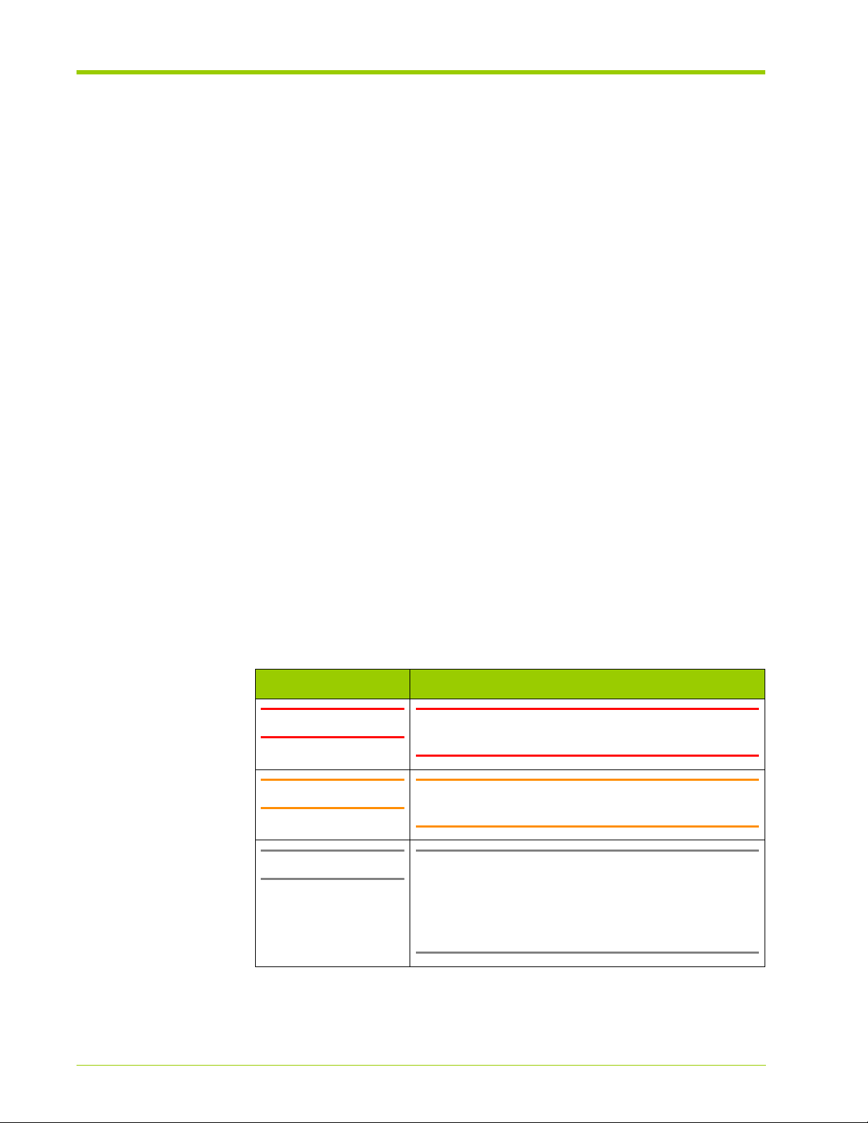
Preface
– Chapter 7, Linux Drivers—Describes how to install, use, and remove the
Linux drivers on a host computer directly attached to the Memory
Array.
– Chapter 8, Windows Drivers—Describes how to install, use, and remove
the Windows drivers on a host computer directly attached to the
Memory Array.
– Chapter 9, Violin Utilities—Describes the Memory Array utility
commands and how to use them.
– Chapter 10, Performance Tuning and Troubleshooting—Describes how
to perform performance tuning and testing on the Memory Array.
• Appendix A, Product Models—Lists the various Memory Array model
configurations.
• Appendix B, Compliance Information—Contains compliance notices and
information for the Memory Array.
• Appendix C, Alarm Reference—Describes the various system alarms that
may occur when using the Memory Array.
• Appendix D, CLI Reference—Describes the commands available in the
Memory Array command line interface.
Document Conventions
Safety Icons
The table below summarizes warning, caution, and note icons used in this
document and includes sample text.
Safety Icons
Icon Sample Text
WARNING! WARNING! Only authorized, qualified, and trained
Caution: Caution: Follow the listed safety precautions when
Note: Note: Read through this entire chapter and plan
personnel should attempt to work on this equipment.
working on the Memory Array.
your installation according to your location before
installing the equipment. The following procedures and
the order in which they appear are general installation
guidelines only.
18
VMA-series Memory Array Installation and Service Guide
HP-AM456-9002A Rev 01
Page 19

Security
Typographical Conventions
The table below summarizes the typographical conventions used in this guide.
Typographical Conventions
Format Meaning
Bold User Interface text.
Italic
Courier
Courier bold
<Courier italic>
[]
|
{}
Security
HP cannot be responsible for unauthorized use of equipment and will not make
allowance or credit for unauthorized use or access.
Reference Documents
Provides emphasis and identifies variables and
document titles.
Command names, examples, and output.
Input you must type exactly as shown.
Information for which you must supply a value.
Optional command parameters are enclosed within
square brackets.
Separates a set of command choices from which only
one may be chosen.
Required command parameters that must be
specified are enclosed within curly brackets.
Contacting HP
HP-AM456-9002A Rev 01
•
vSHARE Memory Gateway Installation and User's Guide
For the name of the nearest HP authorized reseller:
See the Contact HP worldwide (in English) webpage (http://welcome.hp.com/
country/us/en/wwcontact.html).
For HP technical support:
• In the United States, for contact options, see the Contact HP United States
webpage (http://welcome.hp.com/country/us/en/contact_us.html).
To contact HP by phone:
VMA-series Memory Array Installation and Service Guide
19
Page 20

Preface
• Call 1-800-HP-INVENT (1-800-474-6836). This service is available 24
hours a day, 7 days a week. For continuous quality improvement, calls may
be recorded or monitored.
• If you have purchased a Care Pack (service upgrade), call 1-800-633-3600.
For more information about Care Packs, refer to the HP website (http://
www.hp.com/hps).
• In other locations, see the Contact HP worldwide (in English) webpage
(http://welcome.hp.com/country/us/en/wwcontact.html).
For software drivers and firmware downloads:
1. Go to http://www.hp.com/support/downloads.
2. In the Search field on the right-hand side of the page, enter the exact
product name.
3. Select your product.
4. Select your operating system or Cross operating system (BIOS, Firmware,
Diagnostics, etc.). This takes you to the product download page.
5. Select the appropriate download, and follow the instructions.
20
VMA-series Memory Array Installation and Service Guide
HP-AM456-9002A Rev 01
Page 21

PART I
Product Overview
Chapter 1 VMA-series Overview
Chapter 2 Violin Intelligent Memory Modules
Page 22

Page 23

CHAPTER 1 VMA-series Overview
This chapter introduces the VMA-series Memory Array, The VMA-series
Memory Array is the result of a partnership with Violin Memory, Inc. and is based
on the Violin 3000 Series Memory Array. HP and Violin have jointly tested and
certified the system with Linux, Windows, and HP-UX servers.
• Features on page 24
• Physical Components on page 24
• Connectivity and Interfaces Overview on page 28
• System Specifications on page 31
• Direct-attached Host Computer Requirements on page 31
HP-AM456-9002A Rev 01
VMA-series Memory Array Installation and Service Guide
23
Page 24
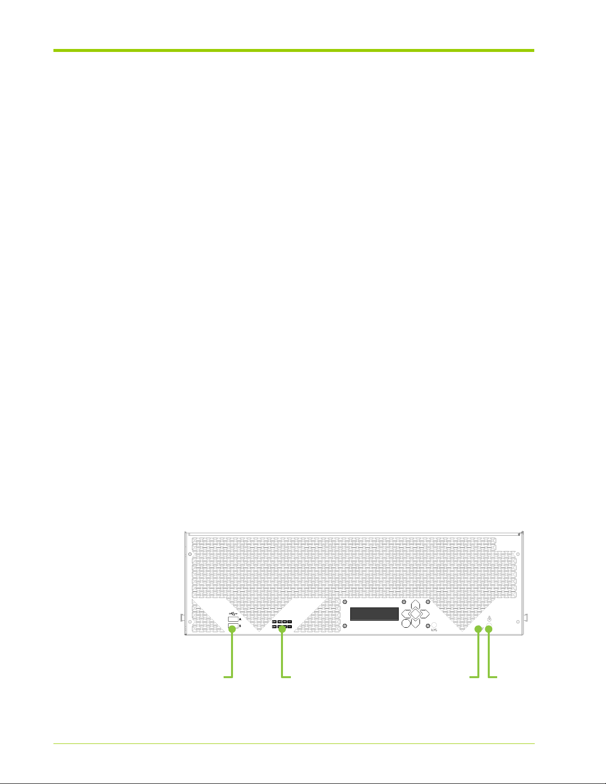
Chapter 1 - VMA-series Overview
A RAID
ADMIN
AC OK
DC OK
STATUS
ALARM
B
USB
Ports
Reset
Button
Front
LEDs
Power
Button
Features
The Memory Array:
• Combines standard memory technology and Violin intelligence to create a
• Operates as a direct-attached or SAN-attached (vSHARE) storage system
• Is designed for highly reliable data center operation. The system is built with
high-bandwidth, high IOPS, low latency, cost-effective memory array.
that can be used for swap space, file systems, or exported as raw Logical
Unit Numbers (LUNs) or devices. Supports fast random or sequential
access operations as there are no mechanical heads to move or spindles to
spin.
• In the base configuration it directly connects via PCI Express (PCIe) to
one or two host computers running Windows or Linux, or to a Memory
Gateway.
• Alternatively, it may be connected to a storage area network (SAN) via
Fibre Channel or Ethernet (iSCSI).
spare Power Supplies, Fans, and Violin Intelligent Memory Modules
(VIMMs).
Physical Components
Chassis
Figure 1.1 illustrates the front view of the Memory Array chassis and Figure 1.2
illustrates the rear view.
Front View
The front panel has the Power and Reset buttons that allow you to start, stop, or
reset the Memory Array.
24
Figure 1.1 Memory Array - Front View
VMA-series Memory Array Installation and Service Guide
HP-AM456-9002A Rev 01
Page 25
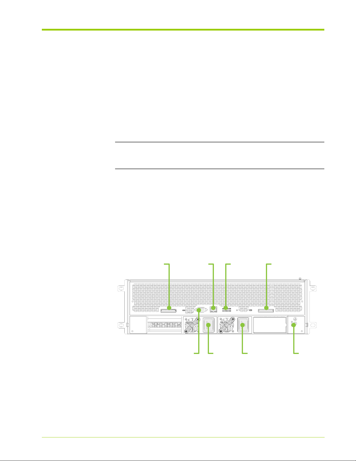
Physical Components
LOC
A RAID
ADMIN
AC OK
DC OK
STATUS
ALARM
B
PCIe
Port 1
PCIe
Port 2
Rear
LEDs
Serial
Console
GND
Ethernet
Port
Power
Supply A
Power
Supply B
The power button on the front of the array can be used to cause the array to
enter into a
With a
shutdown
shutdown
mode similar to executing the shutdown CLI command.
the media is taken offline and I/O stopped to the connected
hosts, but the array is left powered on and able to be managed via the CLI. Use
the reboot CLI command to bring the array media back online and allow I/O to
the connected hosts.
To shut down the system from the front panel, depress the power button for 4
seconds. If the LCD does not indicate the system is shutting down after 10
seconds, depress the power button for another 4 seconds. The LCD should
display that the system is shutdown and it is safe to remove the power cords if
desired.
Note: The array is not actually powered off when using the power button.
Instead the array is logically shut down and the data paths are disabled, placing
the array in a safe mode for removing power cords.
Before turning off power to the Memory Array, shut down any direct-attached
hosts.
Rear View
The rear panel provides the interfaces for connecting input and output devices,
and power supplies. Each interface on the rear of the system has an associated
LED and indicates if the interface is in use or not.
Figure 1.2 Memory Array - Rear View
HP-AM456-9002A Rev 01
System LEDs
Eight system LEDs are located on the front of the Memory Array and four system
LEDs are on the rear.
VMA-series Memory Array Installation and Service Guide
25
Page 26
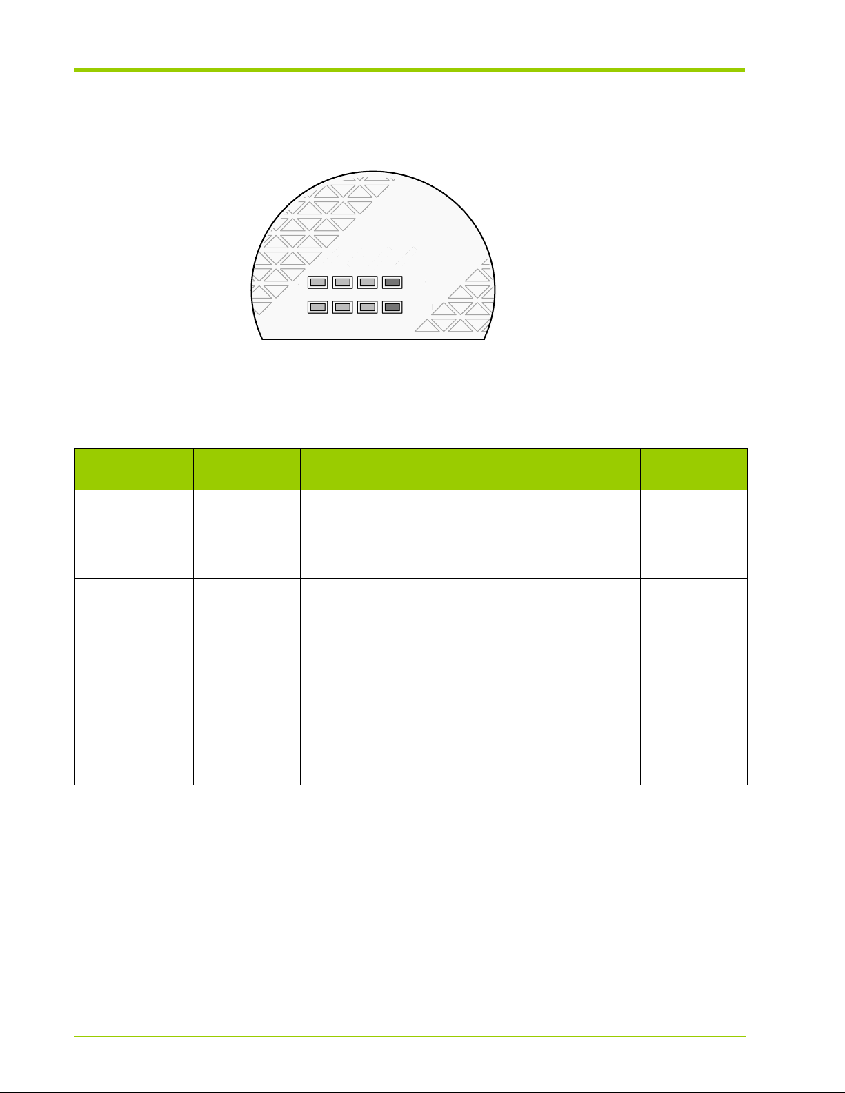
Chapter 1 - VMA-series Overview
A RAID
ADMIN
AC OK
DC OK
STATUS
ALARM
B
A
N
AC OK
ALARM
B
Front LEDs
The front LEDs are illustrated in the figure below.
Figure 1.3 Front System Status LEDs
The front LEDs are described in the following table.
Table 1.1 Front LED Descriptions
DMI
System LED Label Description
A/B AC OK Indicates that the AC power feed to Power Supplies
A and B are connected correctly.
DC OK Indicates that the DC power feed from Power
Supplies A and B are operational.
RAID/ADMIN Status Indicates the system status. When lit, the LED could
be:
• Flashing slowly—Indicates that the system monitor is
booting up.
• Flashing quickly—Indicates that the system software is
booting up, the VIMMs are being detected and
programmed, and no RAID groups have been created.
• Solid green—Indicates that the VIMMs are programmed,
RAID groups are created, and the system software has
completed booting.
Alarm Indicates a system alarm when lit. Red
Color
When Lit
Green
Green
Green
26
VMA-series Memory Array Installation and Service Guide
HP-AM456-9002A Rev 01
Page 27
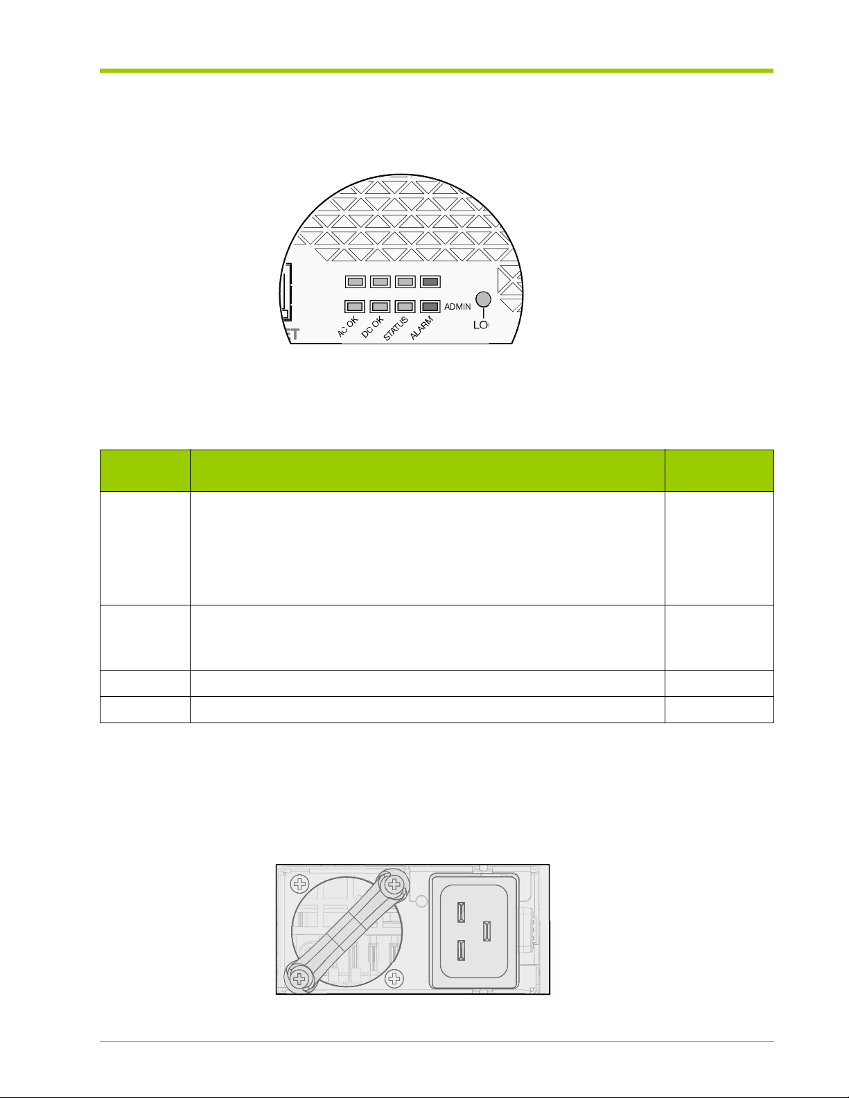
Rear LEDs
LOC
A RAID
AC OK
B
AC
The rear LEDs are illustrated in the figure below:
Figure 1.4 Rear System LEDs
The Rear LEDs are described in the following table.
Table 1.2 Rear LED Descriptions
Physical Components
AI
LED
Label
Description
Status Indicates the system status. When lit, the LED could be:
Color When
Green
• Flashing slowly—Indicates that the system monitor is booting up.
• Flashing quickly—Indicates that the system software is booting up, the VIMMs
are being detected and programmed, and no RAID groups have been created.
• Solid green—Indicates that the VIMMs are programmed, that the RAID groups
are created, and that the system software has completed booting.
Alarm Indicates a system alarm when lit.
Red
When flashing, indicates that the datapath is either severely degraded or
is unavailable.
Power A Indicates that the first power feed is connected correctly. Green
Power B Indicates that the second power feed is connected correctly. Green
Power Supplies
The chassis contains two power supplies that provide an AC power source for
the Memory Array. See System Specifications on page 31 for power supply
specifications.
Lit
HP-AM456-9002A Rev 01
Figure 1.5 Power Supply
VMA-series Memory Array Installation and Service Guide
27
Page 28
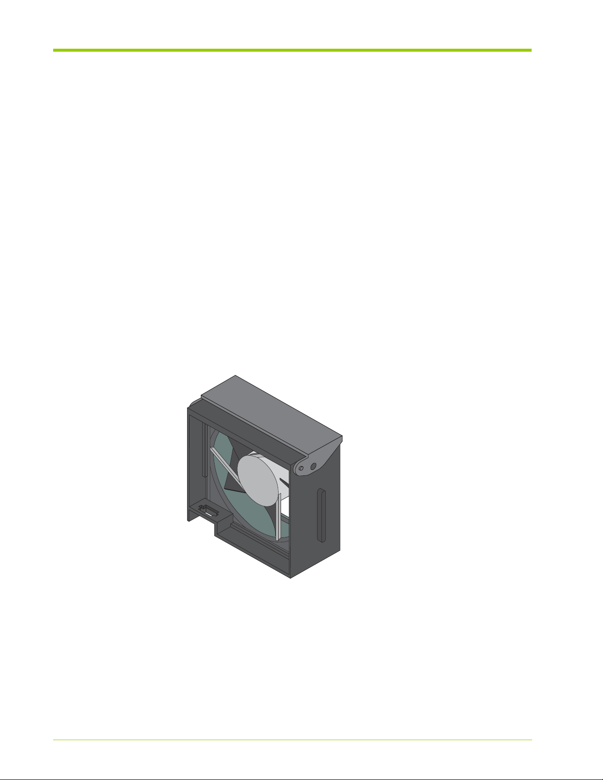
Chapter 1 - VMA-series Overview
The power supplies convert the incoming AC power from individual AC feeds to
DC power used by the system. These 1200 W power supplies are redundant in
their configuration. The power supplies are hot-swappable at any time. See
Connecting the AC Power Cords to the System on page 47 for more information.
The power requirements for the Memory Array are based on the VIMM
configuration used.
• 84 VIMM configurations require over 800 W of power and require short
• 42 VIMM and below configurations require less than 700 W of power. A
Fans
Six fans are located in the front of the chassis and provide forced ventilation for
the Memory Array. The fans plug into connectors inside the front of the chassis.
See Replacing the Fans on page 111 for more information.
term access to 1200 W of power for functions such as formatting. This
level of power cannot be supplied through a single 110 V power supply. It is
required that each power supply be provided a circuit of over 200 V, with
7 A budgeted.
circuit of over 200 V is recommended, but 110 V may be used.
Figure 1.6 Fan Module
Connectivity and Interfaces Overview
The Memory Array contains two types of interfaces:
• Management Interfaces which allow access to the command line interface
(CLI) for system configuration.
• Storage Interfaces which allow connection to a host computer or Memory
Gateway for data transfer.
28
VMA-series Memory Array Installation and Service Guide
HP-AM456-9002A Rev 01
Page 29

Connectivity and Interfaces Overview
Refer to Figure 1.2 for interface locations.
Management Interfaces
Access to the system command line interface (CLI) is available through the
following interfaces:
• DB-9 Serial Debug Interface—Opens the CLI on the system.
• Ethernet Interface—Opens the CLI on the system via Telnet or Secure Shell
(SSH).
See Connecting the Serial Cable on page 50 and Connecting the Ethernet Cable
on page 51 for information.
Storage Interfaces
A single Memory Array may be configured for:
• Direct Attach via PCIe
• SAN attach via Fibre Channel or iSCSI (vSHARE)
Note: System configuration may be changed at any time.
The base platform supports a single PCIe x8 Gen1 (default) interface or dual
PCIe x4 Gen2 (option) interfaces that can directly connect to a host computer
(via a PCIe driver) or to a Memory Gateway. The optional memory gateways
provide specific network interfaces and functions such as SAN block storage or
NFS caching.
Note: The VMA-series Memory Array does not currently support dual PCIe
connections.
PCIe Direct Attach
PCIe provides the lowest latency and highest bandwidth connectivity to the
Memory Array which supports eight lanes of PCIe Gen1 connectivity (20 Gbit/s
line rate). The PCIe connection can go to a single host (PCIe x8) for maximum
bandwidth or two hosts (PCIe x4 each) for reliability. See Connecting the PCIe
Cable to the Memory Array on page 46 for more information.
HP-AM456-9002A Rev 01
Where dual PCIe x4 interfaces are required, a special firmware image is loaded
onto the Memory Array. Similarly, the Memory Array can be changed back to a
single PCIe x8 interface through a new firmware load.
VMA-series Memory Array Installation and Service Guide
29
Page 30

Chapter 1 - VMA-series Overview
Once a Memory Array is connected to a host computer it can be partitioned into
multiple volumes or virtual disks. Both Windows and Linux drivers are supplied
for the specific operating system used on the host.
For data transfers, there are two PCIe x8 interface ports on the rear of the
Memory Array. These interfaces support either single x8 or dual x4 PCIe
connections. The port configuration is determined by the firmware image loaded
on the system. See Upgrading the System Software on page 100 for more
information on changing the firmware image.
For maximum performance to a single host or single memory ga teway, configure
the system data interface as a single PCIe x8 connection using Port 1 (see
Figure 1.2).
For high-availability connections to two hosts or two memory gateways, configure
the system data interface as dual PCIe x4 connections using Ports 1 and 2. This
dual configuration allows each host to read and write to the same address
space. When two hosts write to the same address, however, no guarantees are
made for the order in which the operations are performed; hosts must manage
potential conflicts via a clustered file system (e.g., GPFS) or some other
technique.
Fibre Channel and iSCSI SAN Attach (vSHARE)
vSHARE provides scale-out block storage (SAN) capability. Memory arrays
provide the flash memory storage and Memory Gateways provide the Fibre
Channel and/or iSCSI connectivity and LUN management. Clusters of gateways
and memory arrays can be built for extremely large-scale block storage systems.
Each Memory Array is managed as a container and multiple LUNs (volumes) are
configured on the array. Each LUN can be independently sized and masked for
use by different clients and clusters.
The same memory arrays and memory gateways can also be configured to use
Ethernet (10GbE). Individual servers may be connected via multiple 1 Gb/s or
10Gb/s links to remove performance bottlenecks and extract the most value
out of their processors and DRAM. vSHARE with iSCSI enables 10GbE
connectivity between performance servers and performance flash memory
arrays.
30
VMA-series Memory Array Installation and Service Guide
HP-AM456-9002A Rev 01
Page 31

System Specifications
The table below lists the Memory Array system specifications.
Table 1.3 System Specifications
Specification Description
Electrical Input Power Voltage: 120 V or 240 V
Environmental Ambient Operating Temperature: 5 °C to 35 °C
Interfaces x8 PCIe Interface (2)
System Specifications
Current Capacity: 12 A @ 120 V or 7 A @ 240 V
Short Term: -5 °C to 40 °C
Operating Humidity: 5 to 85% (Non-Condensing)
Short Term: 5 to 90% (Non-Condensing)
Note: When both PCIe interfaces are used they become
x4.
Serial Interface via DB-9 male DTE port
10/100 Ethernet port
Logging Syslog
Management CLI: Serial, Telnet, SSH
Physical Height: 5.19" (3U/132 mm)
Depth: 28.38" (721mm)
Width: 16.915" (430mm)
Minimum Rear Clearance: 7" (178mm)
Maximum Weight: 76 lbs (34.5 kg)
Direct-attached Host Computer Requirements
The table below lists the minimum requirements for a direct-attached host
computer used with the Memory Array.
Table 1.4 Direct-attached Host Computer Requirements
Minimum Requirements
Intel/AMD x86 or x86_64 computer
HP-AM456-9002A Rev 01
An available PCIe slot that communicates with the processor. Slots capable of
bidirectional x8 PCIe provide the best performance.
VMA-series Memory Array Installation and Service Guide
31
Page 32

Chapter 1 - VMA-series Overview
Table 1.4 Direct-attached Host Computer Requirements
Supported Operating Systems:
•Red Hat Enterprise Linux 5.6
• SUSE Linux Enterprise Server 11 SP1
• Windows Server 2008 R2
Serial communications application, such as vtkermit, tip, minicom, kermit,
hyperterm, teraterm, and PuTTY
See Connecting the PCIe Cable to a Host Computer or Memory Gateway on page
53 for more information.
Minimum Requirements
32
VMA-series Memory Array Installation and Service Guide
HP-AM456-9002A Rev 01
Page 33

CHAPTER 2 Violin Intelligent Memory Modules
This chapter describes the Violin Intelligent Memory Module (VIMM) technology,
types, configurations, and slot locations in the following sections:
• Violin Intelligent Memory Modules (VIMMs) on page 34
• VIMM Types on page 34
• VIMM Configurations on page 35
• VIMM Slot Locations on page 35
HP-AM456-9002A Rev 01
VMA-series Memory Array Installation and Service Guide
33
Page 34

Chapter 2 - Violin Intelligent Memory Modules
Violin Intelligent Memory Modules (VIMMs)
A VIMM, illustrated in Figure 2.1:
• Contains memory and interconnect diagnostics and error correction for
data reliability.
• Offers data protection via a flash RAID (4+1Parity) function that provides
fault tolerance and low latency access to flash.
A fully populated system contains up to sixteen Parity VIMMs and four spare
VIMMs for failure protection. All memory modules are hot swappable with
automated rerouting that will not interrupt data service. In the case of a module
failure where the module must be replaced, the Memory Array does not have to
be powered down.
VIMM Types
34
Figure 2.1 VIMMs
WARNING! Insert VIMMs or VIMM blanks only, otherwise permanent
system damage will result.
The Memory Array performance depends on the size of memory used and the
number of modules. VIMMs are available in the capacities listed in the following
table.
Table 2.1 Available VIMM Types
VIMM
Capacity
Raw Memory per Array
(84 VIMMs)
128 GB 10.8 TB
256 GB 21.5 TB
512 GB 43 TB
VMA-series Memory Array Installation and Service Guide
HP-AM456-9002A Rev 01
Page 35

Memory arrays store up to 64, 128, 256, or 512 GB of data per memory
module providing up to 43 TB of raw flash storage per system. The amount of
usable memory in a system is the number of VIMMs used for data storage,
which is four per redundant array of independent disks (RAID) group (up to 64
VIMMs), multiplied by the amount of memory per module, multiplied by the
usable percentage the system is formatted for. For example, in a fully loaded
system with 84 VIMMs, the usable memory is 64 VIMMs multiplied by 128 GB,
multiplied by the usable percentage, such as 87.5%, which is 7.2 TB.
VIMM Configurations
The Memory Array holds up to 84 VIMMs, which operate in the VIMM
configurations listed in the following table.
Table 2.2 VIMM Configurations
VIMMs Active Spare
84 80 4
42 40 2
VIMM Configurations
VIMM Slot Locations
The Memory Array is available in several VIMM configurations. Table 2.3 lists the
VIMM slot numbers used for each configuration. Use the information in the table
when adding, removing, or replacing a non-working VIMM to ensure that the
VIMMs are still in their correct positions. See Replacing VIMMs on page 113 for
information on replacing an errored VIMM.
Table 2.3 VIMM Slot Locations
Number of
VIMMs
42 3, 4, 5, 6, 7, 8, 12, 13, 14, 15, 16, 17, 18, 22, 23, 24,
84 All slots (0-83)
* Designates a filler slot.
Refer to the following section for a VIMM slot location diagram:
Slot Numbers
25, 26, 27, 35, 38, 39, 40, 41, 42, 43, 44, 45, 48, 60,
64, 65, 66, 67, 68, 69, 71*, 75*, 76, 78, 79, 80 (See
Figure 2.2)
HP-AM456-9002A Rev 01
VMA-series Memory Array Installation and Service Guide
35
Page 36

Chapter 2 - Violin Intelligent Memory Modules
54
83
82
81
80
79
78
77
76
75
74
73
72
71
70
69
68
67
66
65
64
63
62
61
60
59
58
57
56
55
00
29
28
27
26
25
24
23
22
21
20
19
18
17
16
15
14
13
12
11
10
09
08
07
06
05
04
03
02
01
30
53
52
51
50
49
48
47
46
45
44
43
42
41
40
39
38
37
36
35
34
33
32
31
Fans
Fans
Fans
42–Module Configuration
For this configuration VIMMs must be placed in the slot locations illustrated in
the following figure.
36
Figure 2.2 VIMM Slot Locations — 42 Modules
All remaining slots must contain blank filler VIMMs. The default spare VIMMs are
located at slots 71 and 75.
VMA-series Memory Array Installation and Service Guide
HP-AM456-9002A Rev 01
Page 37

PART II
Operation
Chapter 3 Installing the Array
Chapter 4 Configuring the Array
Chapter 5 Operating the System via the CLI
Chapter 6 Servicing the Array
Page 38

Page 39

CHAPTER 3 Installing the Array
This chapter describes how to install the Memory Array in the following sections.
• Installation and Configuration Overview on page 40
• Rack-Mounting the Chassis on page 42
• Connecting the PCIe Cable to the Memory Array on page 46
• Connecting Power on page 47
• Connecting Management Network on page 50
• Connecting the PCIe Cable to a Host Computer or Memory Gateway on
page 53
• Routing the Cables onto the Cable Management Arm on page 55
• Powering up the Memory Array on page 56
HP-AM456-9002A Rev 01
VMA-series Memory Array Installation and Service Guide
39
Page 40

Chapter 3 - Installing the Array
2
Rack-Mounting
the Chassis
3
Connecting
PCIe Cables
4
Connecting
Power
1
Unpacking
Components
5
Connecting
Management
Network
PHASE 4:
PHASE 5:
PHASE 1:
PHASE 3:PHASE 2:
Memory Array
Conguration
Hardware Installation
Performance Tuning
and Testing
SAN Storage
Conguration
Direct-Attached
Conguration
2
Troubleshooting
3
Contact
Customer Support
4
Servicing
the System
1
Monitoring
Monitoring and Troubleshooting
Installation and Configuration Overview
Memory Array installation and configuration occurs in five distinct phases:
• Phase 1: Hardware Installation
• Phase 2: Memory Array Configuration
• Phase 3: Storage Configuration
• Phase 4: Performance Testing and Tuning
• Phase 5: Monitoring and Troubleshooting
Figure 3.1 Memory Array Configuration Flowchart
The first phase in the flowchart is described in the current chapter. Phase 2,
memory array configuration, is described in Chapter 4, Configuring the Array.
Phase 3, direct-attach storage configuration, is described in Chapter 7, Linux
Drivers and Chapter 8, Windows Drivers for Linux and Windows respectively; for
SAN (vSHARE) configuration details refer to the
Installation and User's Guide
. Phase 4, performance testing and tuning, is
vSHARE Memory Gateway
described in Chapter 10, Performance Tuning and Troubleshooting and
40
VMA-series Memory Array Installation and Service Guide
HP-AM456-9002A Rev 01
Page 41

Installation and Configuration Overview
Chapter 9, Violin Utilities. Phase 5, monitoring and troubleshooting is described
in Chapter 6, Servicing the Array and Chapter 9, Violin Utilities.
Required Installation Tools and Equipment
The table below lists the tools and equipment required during the installation
process.
Table 3.1 Required Installation Tools and Equipment
Item
#
Item Description Quantity
1 Laptop for console access. DB-9 serial connector or
USB-to-DB-9 cable/dongle.
2 CAT 5 Ethernet Cable with RJ-45 Connectors, straight-
through or cross-over, depending on your installation.
3 Flat Head Screw Driver, size 1/4" 1
4 Phillips Head Screw Drivers, size 2 1
1
1 per array
HP-AM456-9002A Rev 01
VMA-series Memory Array Installation and Service Guide
41
Page 42

Chapter 3 - Installing the Array
Rack-Mounting the Chassis
Installing the Memory Array in a 19" Equipment Rack
The Memory Array fits into a standard 19" (482.6 mm) wide, four-post rack with
sliding rails as specified by EIA-310-D, IEC 60297, and DIN 41494 SC48D.
Square hole racks are supported.
Since there are a variety of 19" equipment racks available, the rack mounting
brackets can be configured in several ways to accommodate a range of frontrear post spacings–from 24" to 32". This adapts the slide rails to the various
equipment racks that may already exist at a customer’s site.
The Memory Array is extended via the slide rails to the front of the rack for live
servicing. A cable management arm is used to manage and extend the cables
for this process. To ensure there is sufficient room for the cable management
arm to easily fit within the rack, it is required that rack depths of 36" or greater
be used. Any doors on the rack must allow good front to back airflow.
Caution:
• Improperly spaced mounting brackets and slide rails can cause the
Memory Array to fall out of the rack.
• Because of the weight of the Memory Array, two people are required to
lift and place the system in an equipment rack.
• If installed in a closed or multi-unit rack assembly, the operating ambient
temperature of the rack environment may be greater than the ambient
room temperature. Therefore, consider installing the equipment in an
environment compatible with the maximum ambient operating
temperature specified by the manufacturer.
• Install the equipment in the rack so that the amount of air flow required
for safe operation of the equipment is not compromised.
• Mount the equipment in the rack so that a hazardous condition is not
achieved due to uneven mechanical loading.
Note: You must be able to access the rear of the Memory Array and the
equipment rack during installation.
The following procedure describes how to:
42
• Install the sliding rails and mounting brackets onto the chassis if they have
not been installed prior to shipping.
• Secure the chassis into the equipment rack. The rack mounting screws and
nuts are included in the shipping package.
VMA-series Memory Array Installation and Service Guide
HP-AM456-9002A Rev 01
Page 43

Rack-Mounting the Chassis
Figure 3.2 Installing the Memory Array into a Rack
To install the Memory Array into a 19" equipment rack:
1. Remove the Memory Array from the shipping packaging and remove all
packing materials. Visually inspect the system for any shipping damage and,
if any damage is detected, contact HP Customer Support for replacement
parts.
2. Install the toolless mounting rails at the appropriate height in your
equipment rack. Orient the rails so they slide out to the front of the rack.
3. Fully extend the rails until they lock into place. Position the Memory Array
above the rails and slide the buttons at the rear sides of the chassis into the
rear slots on the rails.
4. Slip the remaining sets of buttons into the remaining cutouts in the rails.
Push the whole assembly back into the equipment rack and secure the rack
mounting brackets to the front of the equipment rack with the thumb
screws located on the front mounting brackets, as shown in Figure 3.2.
Installing the Cable Management Arm
Install the optional cable management arm at the rear of the chassis. The arm
consists of a mounting bracket and cable holder and keeps the cables from
becoming entangled when the system is fully extended from the equipment rack.
The cables are routed along the length of the arm and held in place with cable
ties. The cable management arm is not installed prior to shipping.
HP-AM456-9002A Rev 01
VMA-series Memory Array Installation and Service Guide
43
Page 44

Chapter 3 - Installing the Array
To install the cable management arm:
1. At the rear of the chassis, remove the shoulder screws and shims from the
rear equipment frame mounting bracket and set aside. Orient the cable
management arm mounting bracket on the right, as illustrated in the figure
below.
Figure 3.3 Installing the Cable Management Arm Mounting Bracket
Align the thumb screws on the cable management arm mounting bracket
2.
with the installation holes on the right rear of the chassis. Securely tighten
the thumb screws into the chassis.
3. Using the four (4) shoulder screws and shims that were set aside in step 1,
secure the cable management arm mounting bracket to the rear
equipment frame mounting bracket, placing the shim between the shoulder
screws and the cable management arm mounting bracket, with the
enclosed Hex key. The cable management arm mounting bracket slides the
arm forward and enables the chassis to be fully extended from the
equipment rack for accessibility.
4. At the rear side of the system, using the two (2) SEM 10-32 x 0.50 screws
included in the shipping package, secure the cable holder to the equipment
rack over the rear equipment frame mounting bracket on the right side of
the system as illustrated in the figure below.
44
VMA-series Memory Array Installation and Service Guide
HP-AM456-9002A Rev 01
Page 45

Rack-Mounting the Chassis
Figure 3.4 Installing the Cable Holder
HP-AM456-9002A Rev 01
VMA-series Memory Array Installation and Service Guide
45
Page 46

Chapter 3 - Installing the Array
LOC
A RAID
ADMIN
AC OK
DC OK
STATUS
ALARM
B
PCIe
Port 1
PCIe
Port 2
Connecting the PCIe Cable to the Memory Array
The Memory Array communicates with the host computer via the PCIe
(Peripheral Component Interconnect Express) connection. The PCIe cable must
be connected to the PCIe port with the flashing LED. The software image on the
system dictates which interface port is used. The image names are listed in the
table below.
Table 3.2 Image Names
Image Name PCIe Interface Interface ID
v3000_Series_x8_p1_df-<release>.upg PCIe x8 Interface for V3000 Port 1
v3000_Series_x4_p1p2_df-<release>.upg Dual PCIe x4 Interfaces for V3000 Ports 1 and 2
Where <release> indicates the release number; for example, A3.7.2-18919.
Note: Ensure that the:
• Bend radius of the PCIe cable is greater than 1.9".
• PCIe cable is connected to the port with the flashing LED.
To connect the PCIe cable to the Memory Array PCIe connector:
1. Locate the appropriate PCIe connector port at the rear of the Memory
Array. This is indicated by the flashing LED that is associated with the port.
Figure 3.5 Connecting the PCIe Cable to the Memory Array
Orient one connector of the PCIe cable so it aligns appropriately with the
2.
PCIe connector at the rear of the Memory Array.
46
3. Securely plug the cable into the PCIe connector port on the Memory Array.
4. If using the cable management arm, route the PCIe cable according to the
instructions in Routing the Cables onto the Cable Management Arm on
page 55.
VMA-series Memory Array Installation and Service Guide
HP-AM456-9002A Rev 01
Page 47
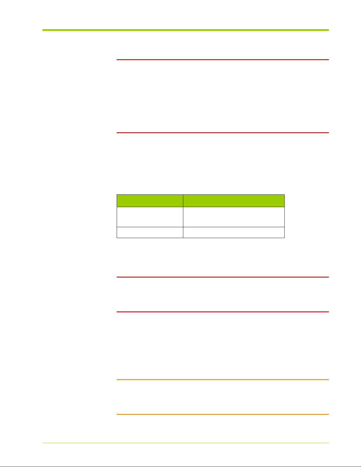
Connecting Power
WARNING! Powering down the system processor interrupts traffic and
causes loss of system logs and diagnostic data. To preserve this diagnostic data
it is recommended that the vincident and/or save log commands be
used prior to powering down the system.
It is recommended to reboot the system rather than powering down then up.
Using a syslog server also ensures logs are stored prior to any reboot or power
down. See Displaying and Setting System Log (Syslog) Options on page 71.
Power Requirements
The Memory Array has the following power requirements:
Table 3.3 Power Requirements
Connecting Power
Item Requirement
Voltage Input Range 180 - 264VAC (1200 W)
90 - 264VAC (1000 W)
Frequency 47-63 Hz
Connecting the AC Power Cords to the System
WARNING! Only authorized, qualified, and trained personnel should attempt
to work on this equipment. Install the Memory Array with a 50 A maximum
branch circuit rating by an end-use application using a UL listed circuit breaker
rated at 50 A.
The Memory Array chassis has the AC power supplies installed prior to shipping.
Connect the AC power cord to either power receptacle on the Memory Array, or
both. Connecting a second power cord is for redundancy purposes.
The power supplies have an IEC-C20 male receptacle and accept an IEC-C19
female connector.
HP-AM456-9002A Rev 01
Caution: Consider the equipment connection to the supply circuit and the
effect that overloading the circuits might have on overcurrent protection and
supply wiring. Also consider the appropriate equipment nameplate ratings when
addressing this concern.
VMA-series Memory Array Installation and Service Guide
47
Page 48

Chapter 3 - Installing the Array
LOC
A RAID
ADMIN
AC OK
DC OK
STATUS
ALARM
B
Power
Supply A
Power
Supply B
Note: The AC power cords are not a standard configuration. Use only the AC
power cords supplied with your system.
To connect the AC power cords to the system:
1. Locate the AC power receptacles at the rear of the system, as shown in the
figure below.
Figure 3.6 AC Power Receptacle Locations
Insert the power connector(s) into the mating power receptacle(s) on the
2.
rear of the Memory Array.
3. If using the cable management arm, route the power cord(s) according to
the instructions in Routing the Cables onto the Cable Management Arm on
page 55.
Connecting Equipment Ground
Connect equipment ground from the equipment rack to the Memory Array only
after installing the system into the equipment rack.
Note:
• Use appropriately sized wire for your equipment application. Minimum
acceptable wire gauge is 8 AWG.
• Maintain reliable earthing of rack-mounted equipment. Supply extra
connections other than the direct connections to the branch circuit
(e.g., using power strips).
48
If ground cable included in accessory kit
1. Using the 2.5 m (8.20 ft) ground cable supplied with the array, attach the
end of the cable with the lug installed to an appropriate grounding point on
the equipment rack. Use an appropriately sized screw to attach the ground
lug to the equipment rack.
VMA-series Memory Array Installation and Service Guide
HP-AM456-9002A Rev 01
Page 49

Connecting Power
2. Route the equipment ground cable to the rear of the equipment. Be sure to
leave an appropriate service loop to allow the removal of the equipment on
the slide rails. If using the cable management arm, route the equipment
ground wire around the arm. See Routing the Cables onto the Cable
Management Arm on page 55.
3. Cut the length of the ground wire at the rear of the equipment as needed
for proper fit. If the length of the cable is cut, strip 13 mm (½ in) of
insulation from the cut end of the cable for installation into the grounding
lug.
4. Attach the ground cable to the loose grounding lug provided with the
Memory Array. Tighten the screw on the lug to secure the cable to the lug.
5. Using the grounding screw provided with the Memory Array, attach the lug
to the ground point on the rear of the equipment.
Note: Attach the lug with the cable pointing up. Attaching the lug with the
cable pointing down may cause interference between the ground cable and
equipment mounted directly below the Memory Array which would prevent
the Memory Array from sliding out of the equipment rack for serviceability.
If ground cable not included in accessory kit
When installing a grounding cable, be sure to allow a sufficient service loop to
allow the array to be removed from the front of the rack for serviceability.
One end of the grounding cable should be attached to an appropriate ground
location on the equipment rack. The other end of the ground cable should be
attached to the grounding location on the rear of the Memory Array using a
¼-20 x ½" (max length) size screw.
HP-AM456-9002A Rev 01
VMA-series Memory Array Installation and Service Guide
49
Page 50

Chapter 3 - Installing the Array
Connecting Management Network
Connecting the Serial Cable
The serial null modem cable connects the host computer to the system’s
debugging interface to retrieve system status and troubleshoot system events.
The default serial port settings are shown in the following table.
Table 3.4 Default Serial Port Settings
Setting Value
Speed (baud rate) 9600
Parity No
# of data bits/character 8
# of stop bits/character 1
Carrier Detect No
Flow Control xon/xoff
The serial cable’s pinout is described in the following table.
T able 3.5 DB-9 to DB-9 Serial Null Modem Cable Pinout
DB-9 Connector 1 DB-9 Connector 2
Description
Female
Connector
Female
Connector
Description
Receive Data 2 3 Transmit Data
Transmit Data 3 2 Receive Data
Data Terminal Ready 4 6+1 Data Set Ready +
Carrier Detect
System Ground 5 5 System Ground
Data Set Ready +
6+1 4 Data Terminal Ready
Carrier Detect
Request to Send 7 8 Clear to Send
Clear to Send 8 7 Request to Send
50
To connect the serial cable to the Memory Array and the host computer:
1. Connect one DB-9 female connector on the serial cable to the male DB-9
connector on the rear of the Memory Array, see Figure 3.7. Secure the
cable to the chassis by tightening the screws on the DB-9 connector.
VMA-series Memory Array Installation and Service Guide
HP-AM456-9002A Rev 01
Page 51

Connecting Management Network
LOC
A RAID
ADMIN
AC OK
DC OK
STATUS
ALARM
B
Serial
Console
Serial
Console
Figure 3.7 Connecting the Serial Cable to the Memory Array
If using the cable management arm, route the serial cable according to the
2.
instructions in Routing the Cables onto the Cable Management Arm on
page 55.
3. At the rear of the host computer, plug the other end of the serial cable into
the male DB-9 connector, see Figure 3.8. Secure the connection by
tightening the screws on the DB-9 connector.
HP-AM456-9002A Rev 01
Figure 3.8 Connecting the Serial Cable to the Host Computer
Connecting the Ethernet Cable
The Ethernet cable connects the host computer to the system’s command line
interface (CLI) for configuration operations and retrieving system status.
For a direct host-to-system Ethernet connection, use a straight-through or crossover RJ-45 to RJ-45 CAT5 Ethernet cable. You can also use a straight-through
or cross-over cable to connect the Memory Array to a router, hub, or other
network device, provided that the host and the system can communicate with
each other.
To connect the Ethernet cable to the Memory Array and the host computer:
1. Connect one RJ-45 connector on the Ethernet cable to the RJ-45
connector labeled ETHERNET on the rear of the Memory Array, as shown in
the figure below.
VMA-series Memory Array Installation and Service Guide
51
Page 52

Chapter 3 - Installing the Array
LOC
A RAID
ADMIN
AC OK
DC OK
STATUS
ALARM
B
Ethernet
Port
Figure 3.9 Connecting the Ethernet Cable to the Memory Array
If using the cable management arm, route the Ethernet cable according to
2.
the instructions in Routing the Cables onto the Cable Management Arm on
page 55.
3. If directly connecting the Memory Array to a host machine, plug the other
end of the cable into the Ethernet connector on the host.
4. If connecting to a network device, such as a router, plug the other end of the
cable into the Ethernet connector on the network device. Use a second
Ethernet cable to connect the host computer to the network device.
52
VMA-series Memory Array Installation and Service Guide
HP-AM456-9002A Rev 01
Page 53

Connecting the PCIe Cable to a Host Computer or Memory Gateway
PCIe
Port
Connecting the PCIe Cable to a Host Computer or Memory
Gateway
The Memory Array is connected via external PCIe cables (PCIe x8 cables) to one
or two host computer(s) or memory gateway(s). Hosts support applications,
such as databases, and run operating systems such as Linux or Windows.
Memory gateways provide network connectivity to SANs or LANs.
The Memory Array can be connected as a direct-attached storage system which
is either dedicated to a single host or shared between two hosts. Where the
Memory Array is shared across two hosts, the PCIe connections are logically
PCIe x4, but use PCIe x8 cables and interfaces.
A single host may connect to multiple memory arrays, enabling capacity and
performance to scale as needed. The host requires a PCIe Host Interface Board
(HIB) for each memory array that is to be connected.
Host Computer
The steps for connecting the Memory Array to a host computer are:
1. Install the necessary PCIe HIB card into an available PCIe slot in the host
computer, ensuring that it is securely seated.
2. Orient the unconnected end of the PCIe cable(s) to align with the PCIe
connector on the back of the host computer. The PCIe cable is keyed and
only goes in one way.
3. Securely plug the cable(s) into the PCIe connector, as illustrated in the
figure below.
Figure 3.10 Connecting the PCIe Cable to the Host Computer
Power-up the Memory Array (see Powering up the Memory Array on page
4.
56). Ensure the RAID/ADMIN Status LED is solid green indicating the PCIe
ports have stabilized before continuing (approximately 1 minute).
HP-AM456-9002A Rev 01
5. Power-up the host computer.
6. If necessary, install the device drivers (see Chapter 7, Linux Drivers or
Chapter 8, Windows Drivers) and reboot the host.
7. Verify the PCIe connection(s).
VMA-series Memory Array Installation and Service Guide
53
Page 54

Chapter 3 - Installing the Array
Memory Gateway
The steps for connecting the Memory Array to a memory gateway are:
1. Orient the unconnected end of the PCIe cable(s) to align with the PCIe
connector on the back of the Memory Gateway. The PCIe cable is keyed and
only goes in one way.
2. Securely plug the cable(s) into the PCIe connector.
3. Power-up the Memory Array (see Powering up the Memory Array on page
56). Ensure the RAID/ADMIN Status LED is solid green indicating the PCIe
ports have stabilized before continuing (approximately 1 minute).
4. Power-up the Memory Gateway.
5. Verify the PCIe connection(s).
Refer to the
information.
vSHARE Memory Gateway Installation and User's Guide
for more
54
VMA-series Memory Array Installation and Service Guide
HP-AM456-9002A Rev 01
Page 55

Routing the Cables onto the Cable Management Arm
Routing the Cables onto the Cable Management Arm
After installing the Memory Array in an equipment rack and attaching the
necessary cables at the rear of the system, route the cables along the cable
management arm to prevent them from becoming entangled when the system
is fully extended from the equipment rack. Route the cables along the length of
the arm and hold in place with cable ties.
To route the cables along the cable management arm:
1. Extend the cable management arm by removing the screws from the
equipment rack, holding the chassis brackets, and pulling out the Memory
Array from the equipment rack. Do not remove the system from the rack.
2. At the rear of the chassis, route the installed ground wire, serial cable, and
power cables along the length of the cable management arm and secure
them with cable ties. Slip the cable ties around the slits in the arm and
secure the ties around the routed cables.
3. Route the PCIe cable along the cable management arm and above the
hinge in the middle of the arm. Routing the PCIe cable above the hinge
ensures that when the system is in place in the equipment rack, the cable
radius stays above the minimum radius for PCIe cables.
Note: The minimum radius bend for a PCIe cable is 1.9".
4. Push the Memory Array back into the equipment rack and secure it to the
equipment frame using the screws that were removed earlier.
HP-AM456-9002A Rev 01
VMA-series Memory Array Installation and Service Guide
55
Page 56

Chapter 3 - Installing the Array
Powering up the Memory Array
After connecting the AC power cords to the Memory Array, and connecting the
PCIe, Ethernet, and serial cables between the Memory Array and the host
computer or memory gateway, apply power to the Memory Array.
To complete the power up sequence:
1. Plug each AC power cord from the chassis into an AC outlet.
2. On the Memory Array, press the power button to start the system boot
process. The LEDs will begin to light up.
Note: Some memory arrays do not have power buttons.
Note: Power up the Memory Array before the host computer to ensure
PCIe communication because PCIe hotplug is not supported by some
current BIOS versions. An alternate method is to reboot the host computer
after powering up the Memory Array to ensure that the host computer
recognizes the system.
3. During the boot up process, the green
flash. The Memory Array is fully booted when the
Status
and the red
Status
LED is continuously
Alarm
LEDs will
lit.
4. Power up the host computer and log in as root on a Linux system, or as an
“administrator” on a Windows system to install the device driver. See
Chapter 7, Linux Drivers, or Chapter 8, Windows Drivers for details. Also,
see Chapter 5, Operating the System via the CLI for information on using
the command line interface (CLI).
56
VMA-series Memory Array Installation and Service Guide
HP-AM456-9002A Rev 01
Page 57

CHAPTER 4 Configuring the Array
When the Memory Array is first powered on, all configuration settings are set to
default values. You must change the default settings to communicate with the
Memory Array over your network(s). This chapter explains how to log into the
Memory Array’s command line interface (CLI) to change system settings, such
as the hostname, IP address, DNS, and syslog options in the following sections.
• Memory Array Default Settings on page 58
• Connecting to the CLI on page 59
• Changing the Default System Settings on page 62
• Configuring DHCP Settings on page 65
• Configuring Domain Name System (DNS) on page 67
• Verifying the Ethernet Connection on page 70
• Displaying and Setting System Log (Syslog) Options on page 71
• Formatting the Memory Array on page 74
HP-AM456-9002A Rev 01
VMA-series Memory Array Installation and Service Guide
57
Page 58

Chapter 4 - Configuring the Array
Memory Array Default Settings
The Memory Array has the system default settings listed in Table 4.1. Change
these settings using the CLI over a Telnet/SSH session or the serial port on the
Memory Array. See Changing the Default System Settings on page 62.
Table 4.1 Memory Array System Default Settings
Setting Default Value
Host Name violin
IP Address 192.168.1.2 (static)
IP Netmask 255.255.255.0
Gateway undefined
DHCP disabled
User Login Name admin
User Password admin
DNS Config manual
DNS Name Server undefined
DNS Search undefined
Clock Source host
Shell Connectivity Serial, Telnet (port 23), SSH (port 22)
Serial Port Settings 9600 Baud, No Parity, 8 bits, 1 stop
System Log (syslog) disabled
Message Logging Level info
Command Line Editor emacs
CLI Window Columns 80
Usable VIMM Capacity 65%
58
VMA-series Memory Array Installation and Service Guide
HP-AM456-9002A Rev 01
Page 59

Connecting to the CLI
Logging into the CLI via the Serial Interface
Access the Command Line Interface (CLI) through the serial connection between
the host computer and the Memory Array. This connection was set up when the
equipment was installed into its permanent location. See Connecting the Serial
Cable on page 50.
See Table 3.4 on page 50 for the serial interface default values.
Note: Your settings for the console connection may vary from the listed
default settings.
Note: Use a USB-to-serial adapter to plug into the serial port on the back of
the Memory Array if your host computer does not have an available serial port.
Connecting to the CLI
Logging in via a Windows host computer
The following procedure shows how to connect to the Memory Array using a
terminal emulation application. For example, using PuTTY to connect to the CLI
through the serial connection:
1. Log into the host computer as an administrator.
2. From the Windows Start menu, select Programs > Accessories >
Communications > PuTTY.
New Connection - PuTTY1
The
3. In the
4. In the Connect using drop-down list, select Serial.
5. Click Connect.
Connection Description
a. Type the name of the new connection in the Name field.
b. Select the appropriate icon from the list of available ones.
c. Click OK when done.
The
Connect To
window opens.
window opens.
window:
The following login prompt appears:
HP-AM456-9002A Rev 01
violin login:
6. Type the default login name (admin) and password (admin) to log into the
system.
You are now connected to the CLI of the Memory Array and can access the
various CLI commands. Closing the PuTTY window terminates the
connection.
VMA-series Memory Array Installation and Service Guide
59
Page 60

Chapter 4 - Configuring the Array
Logging in to the CLI via a Linux host computer
Connect to the Memory Array using the Kermit application or another terminal
application, such as tip, if your system does not have Kermit. Save the Kermit
parameter settings in a .kermrc file so that you do not need to type them each
time you connect. The Violin Utilities package for Linux includes Violin’s version of
Kermit called vtkermit.
Note: Place the .kermrc file in your home directory so that the Kermit
application recognizes it; otherwise, use the -y option followed by the location
and file name of the configuration file.
To connect to the CLI through the serial connection:
1. Log into the host computer as root.
2. At the host computer’s command line prompt, type:
# kermit
or
# vtkermit
3. Specify the line of the Kermit connection. At the Kermit prompt, type:
C-Kermit> set line /dev/ttyS0
Note: The device name may vary depending on the host and the Linux
operating system that is running on the host.
4. Specify the flow control mode. At the Kermit prompt, type:
C-Kermit> set flow xon/xoff
5. Specify the speed of the Kermit connection. At the Kermit prompt, type:
C-Kermit> set speed 9600
6. Since the serial interface of the Memory Array does not require the carrier
detect signal on the Kermit connection, at the Kermit prompt, type:
C-Kermit> set carrier-watch off
7. To establish the connection to the Memory Array, at the Kermit prompt,
type:
60
C-Kermit> connect
The following login prompt appears:
violin login:
8. Type the default login name (admin) and password (admin) to complete
logging into the system.
VMA-series Memory Array Installation and Service Guide
HP-AM456-9002A Rev 01
Page 61

Connecting to the CLI
9. At this point, you are connected to the CLI of the Memory Array and can
access the various CLI commands. To close the Kermit application, do one
of the following:
a. At the CLI prompt, type Ctrl-\, c, and then q.
b. Close the terminal window, which terminates the Kermit connection.
HP-AM456-9002A Rev 01
VMA-series Memory Array Installation and Service Guide
61
Page 62

Chapter 4 - Configuring the Array
Changing the Default System Settings
Table 4.1, Memory Array System Default Settings, on page 58 lists the system
configuration default values.
When you initially log into the Memory Array through the serial interface, change
the following default configuration parameters for security and ease of use.
Table 4.2 Changing the Default System Settings
Setting Details
Hostname See Changing the Hostname.
IP address,
Gateway address,
Netmask
Change the network address information to your
customer location scheme to prevent problems
connecting to the Memory Array. See Changing the
Default IP Address, Netmask, and Gateway on page
63.
Password See Changing the Admin Password on page 62.
To reset back to the factory default settings, see Restoring the Factory Default
Settings on page 103.
Changing the Admin Password
Change the default password for the admin login at any time from the
context level. The admin password must:
• Have a length between 6-12 alphanumeric characters. If six characters are
used, then mix upper/lower case letters with numbers and/or punctuation.
• Be a combination of upper and lower case letters and numbers.
• Not be similar to a previous password.
•Not be a palindrome.
System
62
If you specify an unacceptable password, you will get a message that the
password is
too simple
. By increasing the length of the password, you can use all
lower case or all upper case characters. In other words, the longer the
password, the less complicated it needs to be.
To change the admin password from the default value:
1. Log into the Memory Array.
2. Navigate to the
context system
3. At the
VMA-series Memory Array Installation and Service Guide
System
set admin password
System
context level. At the root prompt, type:
context prompt, type:
HP-AM456-9002A Rev 01
Page 63

Changing the Default System Settings
You will be prompted to enter a new password. If the new password meets
the requirements you will be prompted to enter the same password again.
A message appears indicating that the password has been changed.
The command displays information similar to the following if the new
password does not meet the requirements.
system> set admin password
Changing password for admin
Enter the new password (minimum of 6, maximum of 12 characters)
Please use a combination of upper and lower case letters and num-
bers.
Enter new password:
Bad password: too simple.
passwd: The password for admin is unchanged.
The password remains unchanged if the new one does not meet the
requirements.
Note: You cannot reset the password back to the default password
(admin) for the admin user.
4. To commit the changes made to the password, at the
System
context level
command prompt, type:
save config
Changing the Default IP Address, Netmask, and Gateway
The Memory Array supports assigning IP addresses either statically or through
DHCP. The IP address, netmask, and gateway are initially set to default values,
see Table 4.1. Change these values to valid addresses within your network to
access the system CLI.
By default, DHCP is disabled. For convenience, the Ethernet port supports
automatic medium-dependent interface crossover (Auto-MDIX). With this, you
can connect the Ethernet port on the system to a computer's Ethernet port,
such as a laptop, for provisioning before connecting to a network switch.
You can switch between using DHCP and static addressing. When switching
from DHCP to static addressing, the Memory Array uses the default address
values if new values have not been pre-provisioned in the CLI. Alternatively, an IP
address can be assigned while DHCP is enabled and that IP address is used
automatically when switching from DHCP to static IP address assignment (i.e.,
DHCP is disabled).
HP-AM456-9002A Rev 01
Note: It is recommended to manually configure the IP address of the Memory
Array to use a static IP address in the DHCP configuration file. If the IP address
is automatically assigned there is a risk of the system being assigned a different
IP address upon reboot.
VMA-series Memory Array Installation and Service Guide
63
Page 64

Chapter 4 - Configuring the Array
Note: When you change the IP address of the system, you will be logged off.
Log in again using the new IP address.
To change the system’s IP address, netmask, and gateway from the default
values:
1. Log into the Memory Array.
Note: Use Kermit or vtkermit, instead of Telnet, to change the IP address
in case the IP address is set incorrectly.
2. Navigate to the
context chassis controller ethernet 0
3. At the
Ethernet 0
set ip-address <ip-address>[:<netmask>:<gateway>]
Ethernet 0
context level. At the root prompt, type:
context prompt, type:
Where:
ip-address Specifies the new system IP address.
netmask Specifies the new system netmask.
gateway Specifies the new system gateway address.
Changing the Hostname
To change the system’s hostname from the default value:
1. Log into the Memory Array.
2. Navigate to the system context level. At the root prompt, type:
context system
64
3. At the system command prompt, type:
set name <hostname>
Where:
hostname Specifies the new system hostname.
Note: Depending on your network, you may need to modify the DNS setting to
Telnet to the Memory Array via the hostname. Changing the hostname ensures
that you are connecting to the intended memory array if there are multiple
memory arrays on the network. See Configuring the DNS Name on page 67.
To access the system CLI, specify the new hostname instead of the IP address
in the Telnet session.
VMA-series Memory Array Installation and Service Guide
HP-AM456-9002A Rev 01
Page 65

Configuring DHCP Settings
Configure several DHCP settings and DNS information automatically or manually
on the Memory Array.
Displaying DHCP Status
Display whether or not DHCP is being used to automatically set the system’s IP
address. By default DHCP is disabled.
1. Log into the Memory Array.
Configuring DHCP Settings
2. Navigate to the
context chassis controller ethernet 0
3. At the
Ethernet 0
show
Ethernet 0
context level. At the root prompt, type:
context prompt, type:
When viewing DHCP status, information similar to the following displays:
chassis controller ethernet 0> show
dhcp disabled
ip-address 192.168.1.7
netmask 255.255.255.0
gateway 192.168.1.1
mac-address 00:1B:97:00:00:05
dns-config manual
dns-nameserver undefined
dns-search undefined
Enabling DHCP
Enable DHCP to automatically set the Memory Array’s IP address.
HP-AM456-9002A Rev 01
1. Log into the Memory Array.
2. Navigate to the
context chassis controller ethernet 0
3. At the
4. To commit the changes made to DHCP, at the
Ethernet 0
set dhcp enabled
Ethernet 0
context level. At the root prompt, type:
context prompt, type:
command prompt, type:
save config
VMA-series Memory Array Installation and Service Guide
System
context level
65
Page 66

Chapter 4 - Configuring the Array
Disabling DHCP
Disable DHCP to manually set the Memory Array’s IP address. This is the system
default setting.
1. Log into the Memory Array.
2. Navigate to the
context chassis controller ethernet 0
3. At the
4. To commit the changes made to DHCP, at the
Ethernet 0
set dhcp disabled
Ethernet 0
context level. At the root prompt, type:
context prompt, type:
System
context level
command prompt, type:
save config
If DHCP is disabled, you must manually configure the system’s IP address. See
Changing the Default IP Address, Netmask, and Gateway on page 63.
Once you have manually configured the IP address while DHCP is disabled, you
will see that the manually provisioned IP addresses takes effect.
chassis controller ethernet 0> show
dhcp disabled
ip-address 10.10.0.125
netmask 255.255.255.0
gateway 10.10.0.1
mac-address 00:1B:97:00:00:05
dns-config manual
dns-nameserver undefined
dns-search undefined
66
VMA-series Memory Array Installation and Service Guide
HP-AM456-9002A Rev 01
Page 67

Configuring Domain Name System (DNS)
Configuring Domain Name System (DNS)
There are two available methods for configuring DNS on the Memory Array:
1. Automatic DNS configuration
2. Manual DNS configuration
The Memory Array also allows pre-provisioning the DNS information to use when
you change your system from automatic DNS configuration to manual. If the
DNS configuration is currently in automatic mode, then the current
automatically provisioned DNS name and search information is considered to be
the provisioned settings used when the mode is set to manual.
By default, DNS configuration is performed automatically when Dynamic Host
Configuration Protocol (DHCP) is enabled and connected to a DHCP server that
supports specifying the DNS name. If DHCP is disabled, then the DNS mode is
automatically changed to manual.
Note: Pre-provision the DNS configuration information before disabling DHCP.
Disabling DHCP forces the DNS mode to change to manual and use the default
values, making the system unreachable.
Configuring the DNS Name
When in automatic DNS mode and you set the IP address of the DNS name
server, you are pre-provisioning the value. It is not used until you change the DNS
mode to manual. You can configure the DNS name server’s IP address at any
time.
To specify the IP address of the DNS name server of the Memory Array:
1. Log into the CLI via a serial connection or the Ethernet interface (see
Connecting to the CLI on page 59).
2. Navigate to the
context chassis controller ethernet 0
3. At the
Ethernet 0
set dns-nameserver <ipaddr>
Where:
ipaddr Specifies the IP address of the DNS server.
Ethernet 0
context level. At the root prompt, type:
context prompt, type:
HP-AM456-9002A Rev 01
VMA-series Memory Array Installation and Service Guide
67
Page 68

Chapter 4 - Configuring the Array
Configuring the DNS Search Domain Name
When in automatic DNS mode and you set the DNS search domain name, you
are pre-provisioning the value. It is not used until you change the DNS mode to
manual. You can configure the DNS search domain name at any time.
To specify the search domain name of the Memory Array:
1. Log into the CLI via a serial connection or the Ethernet interface (see
Connecting to the CLI on page 59).
2. Navigate to the
context chassis controller ethernet 0
3. At the
Ethernet 0
set dns-search <value>
Ethernet 0
context level. At the root prompt, type:
context prompt, type:
Where:
value Specifies the search domain name.
In the following example, the DNS name server IP address and the DNS search
domain values have been pre-provisioned.
chassis controller ethernet 0> show
dhcp enabled
ip-address 10.10.0.126
netmask 255.255.255.0
gateway 10.10.0.1
mac-address 00:1B:97:00:00:06
dns-config automatic
dns-nameserver 10.10.0.2
dns-search violintech.net
prov-dns-nameserver 10.10.0.55
prov-dns-search hi-octane-prod.net
68
Displaying the DNS Mode and Preprovisioned Information
To display the current DNS mode and various pre-provisioned DNS information
on the Memory Array:
1. Log into the CLI via a serial connection or the Ethernet interface (see
Connecting to the CLI on page 59).
2. Navigate to the
context chassis controller ethernet 0
VMA-series Memory Array Installation and Service Guide
Ethernet 0
context level. At the root prompt, type:
HP-AM456-9002A Rev 01
Page 69

Configuring Domain Name System (DNS)
3. At the
If DNS is currently in automatic mode, then the status for
show
Ethernet 0
context prompt, type:
dns-config
displays
automatic. In the following example, the DNS name server IP address and the
DNS search domain values have been pre-provisioned.
chassis controller ethernet 0> show
dhcp enabled
ip-address 10.10.0.126
netmask 255.255.255.0
gateway 10.10.0.1
mac-address 00:1B:97:00:00:06
dns-config automatic
dns-nameserver 10.10.0.2
dns-search violintech.net
prov-dns-nameserver 10.10.0.55
prov-dns-search violintech-prod.net
For information on clearing the provisioned DNS settings see Clearing
Provisioned DNS Information on page 89.
Setting the DNS Mode
To set the DNS mode on the Memory Array:
1. Log into the CLI via a serial connection or the Ethernet interface (see
Connecting to the CLI on page 59).
2. Navigate to the
context chassis controller ethernet 0
3. At the
Ethernet 0
set dns-config { manual | auto }
Where:
manual Sets the DNS mode to manual.
auto Sets the DNS mode to automatic.
You can pre-provision the IP address of the name server and the search domain
name while the DNS mode is set to automatic. See Configuring the DNS Name
on page 67 and Configuring the DNS Search Domain Name on page 68. Change
the DNS mode to manual to use the pre-provisioned values.
Ethernet 0
context level. At the root prompt, type:
context prompt, type:
HP-AM456-9002A Rev 01
VMA-series Memory Array Installation and Service Guide
69
Page 70

Chapter 4 - Configuring the Array
Verifying the Ethernet Connection
The Ethernet interface can also be used to connect to the CLI of the Memory
Array. This section explains how to verify that the Ethernet connection is
operating properly.
To verify the Ethernet connection:
1. Log in to the host computer, as root on a Linux host or as an
administrator on a Windows host.
2. To retrieve the IP address of the Memory Array, do one of the following:
a. Log into the CLI via the serial port connection (see Logging into the CLI
via the Serial Interface on page 59) and type the following command at
the command prompt:
show chassis controller ethernet 0
This command returns the system’s IP address and other Ethernet
settings.
b. Connect to your DHCP server and retrieve the IP address it assigned to
your Memory Array.
3. Open a terminal or command line window and, at the command prompt,
type:
$ ping {<memory-array_ip_address> | <memory-array_name>}
Where:
memory-array_ip_address The IP address assigned to the
Memory Array.
memory-array_name The name of the Memory Array if
using DHCP and the memory array
is registered in the DNS.
If the host computer can connect to the Memory Array, then it will return a
successful ping message. If it cannot connect, then a failed ping message is
returned.
You can also connect to the system via the Ethernet port using Telnet or SSH as
described in Connecting to the CLI on page 76. If you are using DHCP and DNS,
you can use the system’s name instead of the IP address to connect through the
network.
70
VMA-series Memory Array Installation and Service Guide
HP-AM456-9002A Rev 01
Page 71

Displaying and Setting System Log (Syslog) Options
Displaying and Setting System Log (Syslog) Options
The Memory Array logs system messages that can be sent to a host running a
syslog server for long term storage. If numerous messages are generated, then
the log buffer may fill up and, since it is a circular buffer, overwrite older
messages. The message level mapping between the message level definitions
and your host’s syslog message level definitions are listed in Table 4.3. View the
man page for syslog.conf on the host for more information.
Table 4.3 Syslog Definition Mappings
Memory Array Syslog
DEBUG debug
INFO info
WARNING warn
ERROR emerg
FATAL emerg
When syslog messages are received on the host, they are written to whatever
logging device is configured. Frequently, this means that warn messages are
written to a file, such as /var/log/messages or /var/adm/messages,
and emerg level messages are written to all root consoles. On the Memory
Array, messages that are set to the WARNING, ERROR, or FATAL level are sent
to the host.
Displaying the Configured IP Address of the Syslog Host
To display the IP address of the syslog host to which the system log messages
will be sent:
1. Log into the Memory Array.
2. Navigate to the
context system logging syslog
3. At the
Syslog
show host
The command displays information similar to the following:.
Syslog
context level. At the root prompt, type:
context prompt, type:
HP-AM456-9002A Rev 01
system logging syslog> show host
host 192.37.87.4
VMA-series Memory Array Installation and Service Guide
71
Page 72

Chapter 4 - Configuring the Array
Setting the IP Address for the Syslog Host
Send system log messages to a host attached to the Memory Array via the
Ethernet port. This host must have syslog configured correctly. See your host’s
syslog documentation for instructions.
Note: From the CLI prompt, use the ping command to verify the connection
between the Memory Array and the remote syslog host.
To set the IP address of the host to which the system log messages will be sent:
1. Log into the Memory Array.
2. Navigate to the
context system logging syslog
3. At the
Syslog
set host <ip_address>
Syslog
context level. At the root prompt, type:
context prompt, type:
Where:
ip_address Specifies the IP address of the syslog host to which
the system log messages will be sent.
4. To commit the change made to the IP address, from the
System
level command prompt, type:
save config
Syslog
Or, from the
top
save config
context level, type:
Or
save system config
context
72
Determining the Status of the System Log Service
Display the status of the service that sends the system log messages to a host.
1. Log into the Memory Array.
2. Navigate to the
context system logging syslog
3. At the
VMA-series Memory Array Installation and Service Guide
Syslog
show service
Syslog
context level. At the root prompt, type:
context prompt, type:
HP-AM456-9002A Rev 01
Page 73

Displaying and Setting System Log (Syslog) Options
The command displays information similar to the following:
system logging syslog> show service
service on
Sending the System Log to a Host
Start or stop the service to send the system log messages to a host. By default,
it is off.
To set the status of the system log service:
1. Log into the Memory Array.
2. Navigate to the
context system logging syslog
3. At the
Syslog
set service {on | off}
Syslog
context level. At the root prompt, type:
context prompt, type:
Where:
on Starts the service that sends the system log messages to the
syslog host.
off Stops the service that sends the system log messages to the
syslog host.
4. To commit the change made, from the
System
context level command
prompt, type:
save config
Or, from the
top
save config
Syslog
context level, type:
HP-AM456-9002A Rev 01
Or:
save system config
VMA-series Memory Array Installation and Service Guide
73
Page 74

Chapter 4 - Configuring the Array
Formatting the Memory Array
Note: The array is formatted to 65% usable capacity at the factory and can
be used without change.
To change the format of the Memory Array:
1. Log into the Memory Array.
2. At the root CLI prompt, type:
format flash-capacity [<value>]
Where:
value Specifies the percentage of usable flash capacity. Valid values
are:
• 50
• 65
• 78
• 84
• 87
• 90 — Not recommended for high performance or high reliability
systems.
Default is 65%.
Higher usable percentages provide more usable capacity where needed. Lower
usable percentages increase system write performance, endurance, and
reliability. For advice on selecting a good usable percentage, consult with HP
Customer Support.
74
VMA-series Memory Array Installation and Service Guide
HP-AM456-9002A Rev 01
Page 75

CHAPTER 5 Operating the System via the CLI
The CLI resides on the Memory Array and is used to retrieve system status and
set configuration information. This chapter describes how to use the CLI to
perform various procedures in the following sections:
• Connecting to the CLI on page 76
• Displaying and Setting the CLI Window Options on page 79
• Displaying and Setting System Information on page 83
• Displaying and Setting Hardware Information on page 92
• Displaying Alarms and Logs on page 96
• Rebooting the Memory Array on page 98
• Upgrading the System Software on page 100
See Appendix D, CLI Reference for details on using the CLI commands.
HP-AM456-9002A Rev 01
VMA-series Memory Array Installation and Service Guide
75
Page 76

Chapter 5 - Operating the System via the CLI
Connecting to the CLI
Connect to the Memory Array’s CLI via SSH or Telnet on the host computer over
the Ethernet interface.
You can also log into the system via the serial port. See Logging into the CLI via
the Serial Interface on page 59 for instructions.
To connect to the Memory Array from a Windows machine, see Logging in via a
Windows host computer on page 59.
Note: The default command line editor for the admin user is
change the default editor to vi, see Setting the Command Line Editor on page 80.
Connecting via SSH
Connect to the CLI via SSH through your host computer.
On a Linux host, use your preferred command shell. On a Windows host, use a
GUI application, such as PuTTY, to SSH to the Memory Array.
The following is an example of what you will see after successfully connecting to
the CLI.
**************************************************************************
* OAM-CLI *
* *
* Operations, Administration & Maintenance - Command Line Interface *
* *
* Copyright (c) 2006-2010, Violin Memory, Inc. All Rights Reserved. *
* *
* S/W Build Info:
* swbuild.violintech.net by user common *
* *
* Release = Release 3.4 *
* *
**************************************************************************
You are at the root node.
Date
17:15:13 *
Emacs
. You can
>
76
Connecting via Telnet
Connect to the CLI via a Telnet session on your host computer.
VMA-series Memory Array Installation and Service Guide
HP-AM456-9002A Rev 01
Page 77

Connecting to the CLI
Note: To connect to the Memory Array from a Windows machine, see Logging
in via a Windows host computer on page 59.
To connect to the Memory Array from a Linux desktop:
1. Right-click on the desktop and select Open Terminal. At the command
prompt in the terminal window, type:
telnet <ip_address>
Where:
ip_address Specifies the IP address of the Memory Array.
2. At the login prompt, type the user login name (default is admin).
3. At the password prompt, type the user password (default is admin).
4. The following is an example of what you will see after successfully
connecting to the CLI.
HP-AM456-9002A Rev 01
VMA-series Memory Array Installation and Service Guide
77
Page 78

Chapter 5 - Operating the System via the CLI
[root@lab5 ~]# telnet 10.10.20.4
Trying 10.10.20.4...
Connected to 10.10.20.4.
Escape character is '^]'.
violin login: admin
Password:
.....
.....
.....
.....
..... ~
..... ~
..... ~
..... ~
..... ~
..... ~ ~ ~
..... ~ ___ ___
..... ~ || // o / o
.. ~ || // .--. / /_-_
~ ||// / / / / / / /
~ ||/ / /___/ / / / /
~ ___ ___
~ ~ //| //|
~ //|| //|| .--. /_ _ .--. /.-- . .
// ||// || /__/ / / / / / / / /
// ||/ || /__ / / / /___/ / /__/
/
http://www.violin-memory.com/ .__/
**************************************************************************
* OAM-CLI *
* *
* Operations, Administration & Maintenance - Command Line Interface *
* *
* Copyright (c) 2006-2010, Violin Memory, Inc. All Rights Reserved. *
* *
* S/W Build Info:
* swbuild.violintech.net by user common *
* *
* Release = R3.4 *
* *
**************************************************************************
You are at the root node.
>
Date
17:15:13 *
78
VMA-series Memory Array Installation and Service Guide
HP-AM456-9002A Rev 01
Page 79

Displaying and Setting the CLI Window Options
Displaying and Setting the CLI Window Options
The settings for the terminal window displaying the current CLI session can be
modified to suit your display equipment. You can set or retrieve the following
window display options:
• Number of columns and lines in the display window
• Pagination
• Command line editing mode
• Size of the history buffer
Displaying the Number of Columns
To view the number of columns in the current CLI display window:
1. Log into the Memory Array.
2. Navigate to the
context cli
3. At the
CLI
show columns
CLI
context level. At the root prompt, type:
context prompt, type:
The command displays information similar to the following:
cli> show columns
Current column setting is: 200
Setting the Number of Columns
Set the number of columns in the display window using the set columns
command. Set the number of columns in the range of 80-200 inclusively, with
the default setting of 80. This determines where the display lines are
automatically wrapped to the next line if you find that your terminal settings are
not wrapping lines correctly.
To set the number of columns in the display window:
HP-AM456-9002A Rev 01
1. Log into the Memory Array.
2. Navigate to the
context cli
3. At the
VMA-series Memory Array Installation and Service Guide
CLI
set columns {80-200}
CLI
context level. At the root prompt, type:
context prompt, type:
79
Page 80

Chapter 5 - Operating the System via the CLI
Displaying the Command Line Edit Mode
1. Log into the Memory Array.
2. Navigate to the
context cli
3. At the
CLI
show edit-mode
CLI
context level. At the root prompt, type:
context prompt, type:
The command displays information similar to the following:.
cli> show edit-mode
Current edit-mode setting is: emacs
Setting the Command Line Editor
Set the command line editor to either
The default editing mode is
1. Log into the Memory Array.
2. Navigate to the
context cli
CLI
Emacs
context level. At the root prompt, type:
.
Emacs
or vi for the current CLI session.
3. At the
CLI
context prompt, type:
set edit-mode {vi | emacs}
Where:
vi Sets the command line editor for the current CLI session
vi
.
to
emacs Sets the command line editor for the current CLI session
to
Emacs
. This is the default.
Displaying the History Buffer Size
1. Log into the Memory Array.
2. Navigate to the
context cli
3. At the
CLI
show history-size
CLI
context level. At the root prompt, type:
context prompt, type:
80
VMA-series Memory Array Installation and Service Guide
HP-AM456-9002A Rev 01
Page 81

Displaying and Setting the CLI Window Options
The command displays information similar to the following:
cli> show history-size
Current history-size setting is: 100
Setting the History Buffer Size
Modify the size of the history buffer to hold from 10-1000 lines.
To modify the number of lines in the history buffer:
1. Log into the Memory Array.
2. Navigate to the
context cli
3. At the
CLI
set history-size {10-1000}
CLI
context level. At the root prompt, type:
context prompt, type:
Displaying the Number of Window Lines
This command is used by the paginator feature to scroll within large amounts of
displayed data, such as when the log is viewed.
1. Log into the Memory Array.
2. Navigate to the
context cli
3. At the
CLI
show lines
The command displays information similar to the following:
cli> show lines
CLI
context level. At the root prompt, type:
context prompt, type:
HP-AM456-9002A Rev 01
Current row setting is: 24
Setting the Number of Window Lines
1. Log into the Memory Array.
2. Navigate to the
context cli
3. At the
VMA-series Memory Array Installation and Service Guide
CLI
set lines {10-100}
CLI
context level. At the root prompt, type:
context prompt, type:
81
Page 82

Chapter 5 - Operating the System via the CLI
Displaying the Pagination Mode
To view whether pagination is enabled or disabled in the current CLI window:
1. Log into the Memory Array.
2. Navigate to the
context cli
3. At the
CLI
show pagination
CLI
context level. At the root prompt, type:
context prompt, type:
The command displays information similar to the following:.
cli> show pagination
Current pagination setting is: on
Setting the Pagination Mode
Enable or disable pagination in the CLI window. When pagination is disabled, data
displays on screen without pausing.
To enable or disable pagination in the CLI window:
1. Log into the Memory Array.
2. Navigate to the
CLI
context level. At the root prompt, type:
context cli
3. At the
CLI
context prompt, type:
set pagination {on | off}
Where:
on Enables pagination in the current CLI window.
off Disables pagination in the current CLI window.
82
VMA-series Memory Array Installation and Service Guide
HP-AM456-9002A Rev 01
Page 83

Displaying and Setting System Information
Displaying and Setting System Information
You can display and set various system information such as the system date and
time, system operational time, the system’s IP address, the log, spare VIMM
information, and RAID group mapping. The following sections describe how to
display and set this information.
Displaying System Status Information
Display the status of the various software modules and the validity of the current
VIMM configuration.
1. Log into the Memory Array.
2. Navigate to the
context system
3. At the
System
show status
System
context level. At the root prompt, type:
context prompt, type:
By default, the display paginates. The example below shows representative text
that may be displayed. Actual text that is displayed is determined by your
system’s configuration.
system> show status
alarm-mgr running
data-mgr running
diagnostics-mgr running
hardware-mgr running
inventory-mgr running
raid-mgr running
vimm-mon running
data-plane available
raid-rebuild active (group 2, vimm 07, 47% complete)
vimm-config out-of-spec-42-vimm
failed-vimm-ids 32, 61
admin-down-vimm-ids 60
missing-vimm-ids 15
host-interfaces
slot port-1
state enabled
protocol pcie
link-width 4
neg-link-width 4
max-data-rate 10 Gb/s
cfg-data-rate 10 Gb/s
host detected
HP-AM456-9002A Rev 01
VMA-series Memory Array Installation and Service Guide
83
Page 84

Chapter 5 - Operating the System via the CLI
slot port-2
state enabled
protocol pcie
link-width 4
neg-link-width 4
max-data-rate 10 Gb/s
cfg-data-rate 10 Gb/s
host detected
slot port-0
state disabled
host undetected
If the VIMM configuration is invalid, or the system is rebuilding the RAID groups,
then up to two extra lines are displayed that list:
• ID numbers of the affected VIMMs
• When the RAID group rebuild is active
• Affected RAID group and VIMM
Displaying the System Operational Time
Display how long a system has been operational since the last time it was
rebooted (i.e., uptime). The time is displayed in tenths of a second and in year, day,
HH:MM:SS
To display how long the system has been operational:
1. Log into the Memory Array.
2. Navigate to the
3. At the
The command displays information similar to the following:.
system> show uptime
tenths-second 132712724
time 0 years, 153 days, 14:27:52
format.
System
context system
System
show uptime
context prompt, type:
context level. At the root prompt, type:
84
Where:
tenths-second Displays how long, in tenths of a second, the system
has been operational since the last power cycle or
system reboot.
VMA-series Memory Array Installation and Service Guide
HP-AM456-9002A Rev 01
Page 85

Displaying and Setting System Information
time Displays how long the system has been operational
since the last power cycle or system reboot in year,
day, hour formats.
Displaying the System Date and Time
1. Log into the Memory Array.
2. Navigate to the
context system
3. At the
System
show clock
System
context level. At the root prompt, type:
context prompt, type:
The command displays information similar to the following:.
system> show clock
clock 2009-07-04T15:39:27
Where:
clock Displays the date and time in the format yyyy-mm-
ddThh:mm:ss.
The T is a delineator between the date and the time.
Setting the System Date and Time
1. Log into the Memory Array.
HP-AM456-9002A Rev 01
2. Navigate to the
context system
3. At the
System
set clock <yyyy-mm-dd>T<hh:mm:ss>
System
context level. At the root prompt, type:
context prompt, type:
Where:
yyyy-mm-dd Sets the date in the format:
• yyyy - The 4-digit year.
• mm - The 2-digit month. Valid values are 01 to 12.
• dd - The 2-digit day. Valid values are 01 to 31.
T The delineator between the date and the time.
hh:mm:ss Sets the time in the format:
• hh - The 2 digit hour. Valid values are 00 to 23.
• mm - The 2-digit minutes. Valid values are 00 to 59.
• ss - The 2-digit seconds. Valid values are 00 to 59.
VMA-series Memory Array Installation and Service Guide
85
Page 86

Chapter 5 - Operating the System via the CLI
Displaying the System Clock Source
The clock source can be the host computer or the Memory Array.
1. Log into the Memory Array.
2. Navigate to the
context system
3. At the
System
show clock-source
System
context level. At the root prompt, type:
context prompt, type:
The command displays information similar to the following:.
system> show clock-source
clock-source host
Setting the System Clock Source
The clock source can be set to the host computer or the Memory Array. The
clock on the system only keeps a running count of the number of seconds that
the system has been operational. It does not keep an accurate calendar date and
time. If the system is rebooted, then the elapsed time is not accounted for when
the system finishes the reboot process and is again operational.
1. Log into the Memory Array.
2. Navigate to the
context system
3. At the
System
set clock-source { host | local }
System
context level. At the root prompt, type:
context prompt, type:
Where:
host Sets the clock source to the host computer. This is the
default value.
local Sets the clock source to the Memory Array.
Displaying the Software Version
1. Log into the Memory Array.
2. Navigate to the
context system version
3. At the
System
show
Version
context level. At the root prompt, type:
context prompt, type:
86
VMA-series Memory Array Installation and Service Guide
HP-AM456-9002A Rev 01
Page 87

Displaying and Setting System Information
The command displays information similar to the following:
system version> show
software version: <release>
software build date: <date> 12:44:52
software build info: built on swbuild.violintech.net by user common
CPL bootloader version: <release>
OAM bootloader version: <release>
CPL OS version: <release>
OAM OS version: <release>
CPL factory image version: <release>
OAM factory image version: <release>
upgrade image version: (<release>_x8ans @ <date> 14:55
controller version info: 15749_x8a @ <date> 11:39
saxpow version info: 8418 @ 03/12/08 15:26
saxled version info: 7642 @ 01/25/08 13:48
Displaying the System IP Information
The following table lists the IP information that can be displayed.
Table 5.1 Displaying IP Information
Label Description
dhcp enabled
ip-address 10.10.0.126
netmask 255.255.255.0
gateway 10.10.0.1
mac-address 00:1B:97:00:00:05
dns-config automatic
dns-nameserver 10.10.0.2
dns-search domain.net
provisioned-info See the following lines:
prov-ip-address 192.168.1.2
prov-netmask 255.255.255.0
prov-gateway 192.168.2.45
HP-AM456-9002A Rev 01
To display the IP address information:
1. Log into the CLI via a serial connection or the Ethernet interface (see
Connecting to the CLI on page 76).
VMA-series Memory Array Installation and Service Guide
87
Page 88

Chapter 5 - Operating the System via the CLI
2. Navigate to the
context chassis controller ethernet 0
3. At the
Ethernet 0
show
Ethernet 0
context level. At the root prompt, type:
context prompt, type:
The command displays text similar to the following:
chassis controller ethernet 0> show
dhcp enabled
ip-address 10.10.0.126
netmask 255.255.255.0
gateway 10.10.0.1
mac-address 00:1B:97:00:00:05
dns-config automatic
dns-nameserver 10.10.0.2
dns-search domain.net
provisioned-info
prov-ip-address 192.168.1.2
prov-netmask 255.255.255.0
This example indicates that DHCP is currently enabled and that the IP address
is currently 10.10.0.126. However, if you were to change the network
configuration to static, the IP address used would be 192.168.1.2.
Displaying the System’s Hostname
1. Log into the Memory Array.
2. Navigate to the
context system
3. At the
System
show name
System
context level. At the root prompt, type:
context prompt, type:
The command displays information similar to the following:.
system name> show
name Violin Memory Array
Retrieving the MAC Address
The MAC address of the Memory Array’s Ethernet port can be found on the back
of the system or in the system attribute files.
To retrieve the device MAC address and serial number, do one of the following:
88
VMA-series Memory Array Installation and Service Guide
HP-AM456-9002A Rev 01
Page 89

Displaying and Setting System Information
1. From the CLI prompt, type:
show chassis controller ethernet 0
2. Log into the host computer and type:
vinfo
To add the Memory Array’s MAC address to your DHCP server, consult your
DHCP server documentation.
Clearing Provisioned IP Information
Provisioned IP address information can be cleared at any time.
1. Log into the CLI via a serial connection or the Ethernet interface (see
Connecting to the CLI on page 76).
2. Navigate to the
context chassis controller ethernet 0
3. At the
Ethernet 0
clear ip-address
Ethernet 0
context level. At the root prompt, type:
context prompt, type:
The command displays information similar to the following:
chassis controller ethernet 0> clear ip-address
chassis controller ethernet 0> show
dhcp enabled
ip-address 10.10.0.126
netmask 255.255.255.0
gateway 10.10.0.1
mac-address 00:1B:97:00:00:06
dns-config automatic
dns-nameserver 10.10.0.2
dns-search violintech.net
Clearing Provisioned DNS Information
HP-AM456-9002A Rev 01
Clear provisioned DNS name server and DNS search domain information.
1. Log into the CLI via a serial connection or the Ethernet interface (see
Connecting to the CLI on page 76).
2. Navigate to the
context chassis controller ethernet 0
VMA-series Memory Array Installation and Service Guide
Ethernet 0
context level. At the root prompt, type:
89
Page 90

Chapter 5 - Operating the System via the CLI
3. At the
4. To commit the changes made, at the
Ethernet 0
clear dns-nameserver
clear dns-search
context prompt, type:
System
context level command
prompt, type:
save config
Displaying the VIMM RAID Group Mapping
The Memory Array supports up to 16 RAID groups per system. Each RAID group
can contain up to five VIMMs and supports data striping across the VIMMs and
RAID groups. Four VIMMs in a RAID group contain data and one contains parity
information. Each RAID group can tolerate a single VIMM failure with no loss of
data.
To display the mapping of the RAID groups across the VIMMs:
1. Log into the Memory Array.
2. Navigate to the
RAID Group
context level. At the root prompt, type:
context raid group <n>
Where:
n Specifies the RAID group number.
3. At the
RAID Group
show maps
context prompt, type:
The command displays information similar to the following:
raid group 2> show maps
group-number 2
id 76,13,44,67,69
state data,data,data,data,data
Where:
group-
Indicates the RAID group ID.
number
id Indicates the physical VIMM ID, and matches the slot
number on the main board.
90
VMA-series Memory Array Installation and Service Guide
HP-AM456-9002A Rev 01
Page 91

Displaying and Setting System Information
state Indicates the state of the VIMM in the 5-VIMM RAID
group. Valid values are:
• data—VIMM is being used for data, either user data or parity
data.
• REBUILDING—VIMM is currently being rebuilt by the RAID
engine to recover from a prior failure.
• FAULT—A fault has occurred for this VIMM. If a spare is
available, a rebuild occurs for this virtual VIMM.
Displaying the Spare VIMM Information
Using the CLI, display the ID numbers of the VIMMs that are designated as
spares for use with the RAID groups.
1. Log into the Memory Array.
2. Navigate to the
context raid
3. At the
RAID
show spare-ids
RAID
context level. At the root prompt, type:
context prompt, type:
The command displays information similar to the following:
raid> show spare-ids
spare-ids 30,31,32,52
HP-AM456-9002A Rev 01
VMA-series Memory Array Installation and Service Guide
91
Page 92

Chapter 5 - Operating the System via the CLI
Displaying and Setting Hardware Information
Display hardware information for the Memory Array, including:
• Fan tray status
• Which slots are populated with VIMMs
• Individual VIMM information
•Test slots
•System LEDs
Displaying VIMM Configuration Information
Display the VIMM configuration information at the
To display the VIMM configuration information:
1. Log into the Memory Array.
2. Navigate to the desired
context chassis board 0 slot <n>
Slot
context level. At the root prompt, type:
Where:
n
Specifies the VIMM slot number to move to. Valid values are in
the range of 0–83, inclusive.
3. At the context prompt, type:
show vimm
This command displays text similar to the following:
chassis board 0 slot 56> show vimm
admin-state up
oper-state up
vimm-state active
raid-group 0
vimm-type FLASH
mem-type SLC-NAND
raw-capacity 68.7GB (64GiB)
raw-capacity-bytes 68,719,476,736
fmt-capacity 45.1GB (42GiB)
fmt-capacity-bytes 45,097,156,608
part-number 1000159A-B-P4
serial-number 18094R00000003
mfg-date 20090422
fw-date Thu Feb 11 17:54:00 2010
fw-version 0x39df
Slot
context level.
92
VMA-series Memory Array Installation and Service Guide
HP-AM456-9002A Rev 01
Page 93

Displaying and Setting Hardware Information
sw-date Fri Feb 12 00:07:00 2010
sw-version 0x39dd
is-programmed true
id-assigned true
environment
temperature 66C (OK)
sensor-1.2v 1.14
sensor-1.8v 1.79
sensor-2.5v 2.42
sensor-3.3v 3.35
run-time-stats
run-time 0 years, 0 days 15:22:04
stats-date Wed Feb 17 10:37:39 2010
format-date Tue Feb 16 19:41:08 2010
user-reads 130,233,145
user-read-bytes 133,358,740,480
user-writes 130,233,037
user-write-bytes 133,358,629,888
ecc-cor-counts
one-bit 3
two-bits 0
three-bits 0
four-plus-bits 0
total-cor 3
ecc-corrected 3 (rate: 2.30e-08)
raid-corrected 0 (rate: 0.00e+00)
blk-boot-fails 0
blk-erase-fails 0
blk-prog-fails 0
blk-ecc-thresh 0
blk-ecc-uncor 0
erase-counts
blk-erase-target 100,000
blk-erase-avg 18.20
flash-health
failed-blocks 342 (0.13%)
failed-die 0 (0.00%)
perform-thresh 0.95% (OK)
rebuild-thresh 0.64% (OK)
critical-thresh 0.48% (OK)
HP-AM456-9002A Rev 01
Displaying the Number of VIMMs
Display the number of VIMMs in the system, the corresponding slot ID number,
and the VIMM type.
To display a summary of VIMMs currently installed:
1. Log into the Memory Array.
2. Navigate to the
context chassis board 0
VMA-series Memory Array Installation and Service Guide
Board 0
context level. At the root prompt, type:
93
Page 94

Chapter 5 - Operating the System via the CLI
3. At the context prompt, type:
show vimm-summary
The command displays information similar to the following:
chassis board 0> show vimm-summary
num-vimms 42
installed-vimm-ids 3-8,12-18,22-27,35,38-45,48,60,64-69,71,75,76,78-80
flash-vimm-ids 3-8,12-18,22-27,35,38-45,48,60,64-69,71,75,76,78-80
admin-down-vimm-ids 39
installed-mem-raw 2886.2GB (2688GiB)
usable-mem-raw 2199.0GB (2048GiB)
parity-mem-raw 549.8GB ( 512GiB)
spare-mem-raw 68.7GB ( 64GiB)
unavailable-mem-raw 68.7GB ( 64GiB)
formatted-percentage 78.1%
usable-mem-formatted 1718.0GB (1600GiB)
Displaying Fan Status
Display the status of the system fans for maintenance and troubleshooting
1
purposes. The fans are located in two fan trays designated as
(bottom), and the fans are designated as
Left, Center
, and
(top) and 2
Right
.
To display the current status of the fans:
1. Log into the Memory Array
2. Navigate to the desired
context chassis fan-tray {1 | 2}
Fan
context level. At the root prompt, type:
Where:
1 Specifies the top fan tray.
2 Specifies the bottom fan tray.
3. At the context prompt, type:
show fan {left | center | right}
Where:
left Specifies the left fan in the specified fan tray.
center Specifies the center fan in the specified fan tray.
94
right Specifies the right fan in the specified fan tray.
VMA-series Memory Array Installation and Service Guide
HP-AM456-9002A Rev 01
Page 95

Displaying and Setting Hardware Information
The command displays information similar to the following:.
chassis fan-tray 1> show fan left
speed high
rpm 4800
Displaying Main Board Information
1. Log into the Memory Array.
2. Navigate to the
context chassis board 0
3. At the context prompt, type:
show info
Board 0
context level. At the root prompt, type:
The command displays information similar to the following:.
chassis board 0> show info
part-number 1000074S-C-08
version 0
serial-number 16095R00000237
mfg-date 20090723
environment
ambient-temp 36C (OK)
controller-temp 57C (OK)
sensor-12v-a 11.80
sensor-12v-b 11.83
HP-AM456-9002A Rev 01
VMA-series Memory Array Installation and Service Guide
95
Page 96

Chapter 5 - Operating the System via the CLI
Displaying Alarms and Logs
Display the current alarms that light the System LED on the Memory Array to
help prevent system damage in the case of a fan failure, lid removal, or to
diagnose performance problems when one or more VIMMs are affected by high
temperatures.
See Appendix C, Alarm Reference for more information on alarms.
If the alarms and logs do not provide enough information to resolve an issue, run
the vincident utility to collect information from the host computer and
memory array, and contact HP Customer Support (or service provider). See
vincident on page 155 and Contacting HP on page 19.
Displaying the Current Alarms
1. Log into the Memory Array.
2. Navigate to the
context system alarms
3. At the
System
show
System
context level. At the root prompt, type:
context prompt, type:
The command displays information similar to the following:
system> show alarms
alarm1 Lid removed
alarm2 Top fan tray removed
alarm3 Bottom-left fan running too slowly, 2000 RPM
alarm4 VIMM 14 low 1.8V, 1.68 volts; VIMM shut down
alarm5 VIMM 68: hot, 71 C
Displaying the System Log
Display the data contained in the log on the Memory Array. The log is displayed
in a paginator window, unless you have disabled the paginator options. Setting
the Pagination Mode on page 82 for detailed instructions on using the window
pagination.
96
To display the system’s log:
1. Log into the Memory Array.
2. Navigate to the
context system
3. At the
VMA-series Memory Array Installation and Service Guide
System
show log
System
context level. At the root prompt, type:
context prompt, type:
HP-AM456-9002A Rev 01
Page 97

Displaying Alarms and Logs
The command displays information similar to the following:
system> show log
xxx xx xx:xx:xx [000000000] INFO vtu_log_init(): ------------ LOG RESTART -----------xxx xx xx:xx:xx [000000010] INFO ecpu_hwmgr_init(): Running fans at full speed
xxx xx xx:xx:xx [000000010] INFO main(): Main controller build ID: 12954
xxx xx xx:xx:xx [000000010] INFO main(): S/W Rel: <release>, Built: <date> 12:16:39 on
swbuild.violintech.net by user common
Displaying the Messages Log
The embedded operating system running on the Memory Array produces a
message log similar to the /var/log/messages file found on Linux operating
systems. The message log file created on the Memory Array contains system log
and typical boot-up messages in addition to any set CLI commands that are run
on the system.
To display the messages log file:
1. Log into the Memory Array.
2. Navigate to the
context system
3. At the
System
show messages
System
context level. At the root prompt, type:
context prompt, type:
The command displays information similar to the following:.
system> show messages
Nov 30 00:28:22 kernel: Linux version 2.6.17.11719 (common@swbuild.violintech.net) (g cc
version 3.4.6) #2 PREEMPT Mon Dec 22 12:38:51 EST 2008
Nov 30 00:28:22 kernel: ^O^M
Nov 30 00:28:22 kernel:
Nov 30 00:28:22 kernel: uClinux/Nios II
Nov 30 00:28:22 kernel: Altera Nios II support (C) 2004 Microtronix Datacom Ltd.
Nov 30 00:28:22 kernel: On node 0 totalpages: 32512
Nov 30 00:28:22 kernel: DMA zone: 32512 pages, LIFO batch:7
Nov 30 00:28:22 kernel: Built 1 zonelists
Nov 30 00:28:22 kernel: Kernel command line: CONSOLE=/dev/ttyS0 root=/dev/ram0 rw
panic=10 mtdparts=violin-0:256k(BOOTROM)ro,128k(ENV1),128k(ENV2),1536k(FLATFS3),32m
(UPGRADE),8m(CPLgold)ro,16m(OAMgold)ro,6016k(SPARE) oeth_mac=00:1b:97:00:00:86
Nov 30 00:28:22 kernel: PID hash table entries: 512 (order: 9, 2048 bytes)
Nov 30 00:28:22 kernel: Dentry cache hash table entries: 16384 (order: 4, 65536 bytes)
Nov 30 00:28:22 kernel: Inode-cache hash table entries: 8192 (order: 3, 32768 bytes)
Nov 30 00:28:22 kernel: Memory available: 122496k/130048k RAM, 0k/0k ROM (1707k kernel
code, 4607k data)
HP-AM456-9002A Rev 01
VMA-series Memory Array Installation and Service Guide
97
Page 98

Chapter 5 - Operating the System via the CLI
Rebooting the Memory Array
When you reboot the Memory Array, you must specify which processors to
restart. The two processors are:
1. System—Contains the software that manages the VIMM topology.
WARNING! Restarting the system processor interrupts traffic and
causes loss of some older system logs and diagnostic data. To preserve this
diagnostic data it is recommended that the vincident and/or save
log commands be used prior to reboot.
Using a syslog server also ensures logs are stored prior to any reboot. See
Displaying and Setting System Log (Syslog) Options on page 71.
2. OAM—Controls the administration function, such as user logins, system
administration, and the CLI software.
Rebooting the System
Set the system reboot to run immediately or to be delayed in minutes, up to 1
day.
1. Log into the Memory Array.
2. At the root prompt, type:
reboot system {all | oam} [delay <n>]
Where:
all Reboots both the
System
and
OAM
processors.
oam Reboots only the OAM processor
delay <n> Sets the time delay in minutes for rebooting the
system.
Valid values are in the range of 1 to 1440.
If you do not specify the time delay, you are also prompted whether you want to
reboot the system immediately. Answer y to reboot immediately. If you answer
n, the immediate reboot request is cancelled.
You are prompted to confirm scheduling the reboot. If you confirm the reboot it
will be scheduled. While the system is rebooting, you will lose your CLI connection
and have to log back into the interface.
98
Canceling a Scheduled Reboot
1. Log into the Memory Array.
VMA-series Memory Array Installation and Service Guide
HP-AM456-9002A Rev 01
Page 99

Rebooting the Memory Array
2. Navigate to the
cancel reboot
3. You will be prompted to confirm the cancelation of the reboot. Type y to
System
context level. At the root prompt, type:
confirm cancelling the reboot or type n to keep the scheduled reboot.
Displaying the Scheduled Reboot
To display when a reboot is scheduled to run:
1. Log into the Memory Array.
2. Navigate to the
context system
3. At the
System
show reboot
The command displays information similar to the following:
system> show reboot
System
context level. At the root prompt, type:
context prompt, type:
There is a reboot scheduled in 14 minute(s) and 8 seconds.
HP-AM456-9002A Rev 01
VMA-series Memory Array Installation and Service Guide
99
Page 100

Chapter 5 - Operating the System via the CLI
Upgrading the System Software
To upgrade the software on the Memory Array, perform the following steps:
1. Copy the upgrade image to a location on a host that is accessible to the
Memory Array target system using FTP, HTTP, NFS, SCP, SFTP, or TFTP.
2. Set the upgrade path to the above location. The upgrade image will
download to the upgrade partition of the Memory Array.
3. Set the upgrade partition to activate upon bootup.
4. Schedule the system reboot.
5. Reboot the host server.
6. Update the system software factory image.
Note:
• If you are upgrading from a previous release to the most current
release, see the user documentation associated with the previous
release for detailed upgrade instructions.
• If you are upgrading from a release prior to R2.2.0, before rebooting,
you must use the following command to make the upgrade partition
active upon reboot:
set system sw-upgrade active upgrade
The file name of the upgrade image is different depending on the PCIe interface
you are using to connect to the Memory Array. The table below lists the image
names.
Table 5.2 Upgrade Image Names
Image Name
Use for PCIe
Interface
Interface ID
vtms-array-firmware-x4x4-<release>.upg dual-x4 interface Ports 1 and 2
vtms-array-firmware-x8-<release>.upg single x8 interface Port 1
Where <release> indicates the release number; for example, A3.7.2-18919.
100
VMA-series Memory Array Installation and Service Guide
HP-AM456-9002A Rev 01
 Loading...