

Page 1

HP Integrity Virtual Machines
Installation, Configuration, and
Administration
HP Integrity Virtual Machines Version 2.0
*T2767-90024*
Printed in the US
HP Part Number: T2767-90024
Published: October 2006, Edition 2
Page 2

© Copyright 2006 Hewlett-Packard Development Company, L.P.
Legal Notices
Confidential computersoftware. Valid license from HP required for possession, use or copying. Consistent with FAR 12.211 and12.212, Commercial
Computer Software, Computer Software Documentation, and Technical Data for Commercial Items are licensed to the U.S. Government under
vendor's standard commercial license.
The informationcontained hereinis subject to change without notice. Theonly warranties for HP products and services are setforth inthe express
warranty statements accompanying such products and services. Nothing herein should be construed as constituting an additional warranty. HP
shall not be liable for technical or editorial errors or omissions contained herein.
Acknowledgments
HP-UX Release 10.20 and later and HP-UX Release 11.00 and later (in both 32 and 64-bit configurations) on all HP 9000 computers are Open
Group UNIX 95 branded products.
UNIX is a registered trademark of The Open Group.
Microsoft and Windows are U.S. registered trademarks of Microsoft Corporation.
Intel and Itanium are trademarks or registered trademarks of Intel Corporation or its subsidiaries in the United States and other countries.
Page 3

Table of Contents
About This Document.......................................................................................................11
1 Intended Audience................................................................................................................................11
2 New and Changed Information in This Edition........................................................................................11
3 Typographic Conventions......................................................................................................................11
4 Product Naming Conventions................................................................................................................11
5 Document Organization.........................................................................................................................12
6 Related Information...............................................................................................................................12
7 Publishing History.................................................................................................................................13
8 HP Encourages Your Comments.............................................................................................................13
1 Introduction...................................................................................................................15
1.1 About HP Integrity Virtual Machines...................................................................................................15
1.2 Running Applications in the Integrity VM Environment........................................................................16
1.3 Related Products.................................................................................................................................17
1.4 Using This Manual..............................................................................................................................18
1.5 Using the Integrity VM Documentation................................................................................................18
1.5.1 Integrity VM Manpages...............................................................................................................18
1.5.2 Help Files...................................................................................................................................19
2 Installing Integrity VM..................................................................................................21
2.1 Installation Requirements....................................................................................................................21
2.1.1 VM Host System Requirements....................................................................................................21
2.1.2 Bundle Names............................................................................................................................22
2.1.3 Using VM Manager Requires the Latest WBEM Services on the VM Host........................................22
2.2 Installation Procedure.........................................................................................................................22
2.3 Upgrading from Earlier Versions of Integrity VM..................................................................................23
2.4 Verifying the Installation of Integrity VM..............................................................................................24
2.5 Removing Integrity VM.......................................................................................................................24
2.6 Reserving VM Host Devices.................................................................................................................24
2.7 Troubleshooting Installation Problems..................................................................................................25
2.7.1 Error messages during installation...............................................................................................25
3 Creating Virtual Machines..........................................................................................27
3.1 Specifying Virtual Machine Characteristics...........................................................................................27
3.1.1 Virtual Machine Name.................................................................................................................27
3.1.2 Guest Operating System..............................................................................................................28
3.1.3 Virtual CPUs...............................................................................................................................28
3.1.4 Entitlement.................................................................................................................................28
3.1.5 Guest Memory Allocation............................................................................................................29
3.1.6 Virtual Devices............................................................................................................................29
3.1.7 Creating Virtual Network Devices................................................................................................29
3.1.8 Creating Virtual Storage Devices..................................................................................................30
3.2 Using the hpvmcreate Command.........................................................................................................31
3.2.1 Example of Virtual Machine Creation...........................................................................................33
3.3 Starting Virtual Machines....................................................................................................................33
3.4 Changing Virtual Machine Configurations............................................................................................34
3.5 Cloning Virtual Machines....................................................................................................................37
3.6 Stopping Virtual Machines..................................................................................................................37
3.7 Removing Virtual Machines.................................................................................................................38
3.8 Troubleshooting Virtual Machine Creation Problems.............................................................................39
3.8.1 Configuration Error on Starting the Virtual Machine.....................................................................39
Table of Contents 3
Page 4

4 Creating HP-UX Guests................................................................................................41
4.1 Installing the HP-UX Guest Operating System......................................................................................41
4.2 Installing HP-UX Guest Management Software.....................................................................................44
4.3 Troubleshooting HP-UX Guest Creation...............................................................................................44
4.3.1 The guest hangs in the EFI shell...................................................................................................44
5 Creating Windows Guests..........................................................................................47
5.1 Windows Guest Requirements.............................................................................................................47
5.2 Installing Windows Guests..................................................................................................................47
5.2.1 Installing from HP Reinstall (OPK) Media.....................................................................................49
5.2.2 Installing from Windows Media...................................................................................................53
5.3 Managing Windows Guests.................................................................................................................57
5.4 Installing Integrity VM Windows Guest Management Software.............................................................60
5.5 Troubleshooting Windows Guest Installation........................................................................................60
5.5.1 Remote desktop unable to connect................................................................................................60
6 Creating Virtual Storage Devices...............................................................................61
6.1 Introduction to Integrity VM Storage....................................................................................................61
6.1.1 Integrity VM Storage Goals..........................................................................................................61
6.1.1.1 Storage Utilization...............................................................................................................61
6.1.1.2 Storage Availability.............................................................................................................61
6.1.1.3 Storage Performance............................................................................................................61
6.1.1.4 Storage Security..................................................................................................................61
6.1.1.5 Storage Configurability........................................................................................................62
6.1.2 Integrity VM Storage Architectures..............................................................................................62
6.1.2.1 Shared I/O..........................................................................................................................62
6.1.2.2 Attached I/O.......................................................................................................................62
6.1.3 Integrity VM Storage Implementations.........................................................................................63
6.1.3.1 Integrity VM Storage Adapters.............................................................................................63
6.1.3.2 Integrity VM Storage Devices...............................................................................................63
6.1.3.2.1 Attached Devices.........................................................................................................63
6.2 Configuring Integrity VM Storage........................................................................................................64
6.2.1 Integrity VM Storage Considerations............................................................................................64
6.2.1.1 VM Storage Supportability...................................................................................................64
6.2.1.2 Performance of Virtual Devices............................................................................................64
6.2.1.3 VM Storage Multipath Solutions...........................................................................................66
6.2.1.4 VM Storage Management.....................................................................................................67
6.2.1.5 VM Storage Changes...........................................................................................................68
6.2.1.6 Virtual Storage Setup Time ..................................................................................................69
6.2.2 Setting up Virtual Storage............................................................................................................69
6.2.2.1 VM Guest Storage Specification............................................................................................69
6.2.2.2 VM Host Storage Specification.............................................................................................70
6.2.2.3 VM Storage Resource Statements..........................................................................................71
6.2.2.3.1 Virtual Disks...............................................................................................................71
6.2.2.3.2 Virtual PartDisks.........................................................................................................72
6.2.2.3.3 Virtual LvDisks...........................................................................................................73
6.2.2.3.4 Virtual FileDisks..........................................................................................................76
6.2.2.3.5 Virtual DVDs..............................................................................................................76
6.2.2.3.6 Virtual FileDVDs.........................................................................................................77
6.2.2.3.7 Virtual NullDVDs........................................................................................................78
6.2.2.3.8 Attachable Devices......................................................................................................79
6.3 Using Integrity VM Storage.................................................................................................................82
6.3.1 Integrity VM Storage Roles..........................................................................................................82
6.3.1.1 VM Host Administrator.......................................................................................................82
6.3.1.2 Guest Administrator............................................................................................................83
6.3.1.3 Guest User..........................................................................................................................83
6.3.2 Integrity VM Storage Use Cases...................................................................................................83
4 Table of Contents
Page 5

6.3.2.1 Adding Virtual Storage Devices............................................................................................83
6.3.2.2 Deleting VM Storage Devices...............................................................................................84
6.3.2.3 Modifying VM Storage Devices............................................................................................84
7 Creating Virtual Networks..........................................................................................89
7.1 Introduction to Virtual Network Configuration.....................................................................................89
7.2 Creating Vswitches.............................................................................................................................90
7.2.1 Local Networks...........................................................................................................................91
7.2.2 Configuring Guest Virtual Networks............................................................................................91
7.3 Deleting Vswitches..............................................................................................................................92
7.4 Recreating Vswitches..........................................................................................................................93
7.5 Starting Vswitches...............................................................................................................................93
7.6 Halting Vswitches...............................................................................................................................93
7.7 Managing VNICs................................................................................................................................93
7.7.1 Removing VNICs........................................................................................................................94
7.8 Configuring VLANs............................................................................................................................94
7.8.1 Cloning Guests with VLAN Information.......................................................................................96
7.8.2 Displaying VLAN Information.....................................................................................................97
7.8.3 Configuring VLANs on Physical Switches....................................................................................98
7.9 Troubleshooting Network Problems.....................................................................................................98
7.9.1 Redefining PNICs........................................................................................................................98
7.9.2 Troubleshooting VLAN Problems.................................................................................................99
8 Managing Guests......................................................................................................101
8.1 Monitoring Guests.............................................................................................................................101
8.2 Creating Guest Administrators and Operators.....................................................................................103
8.3 Creating the Guest Management Software Repository..........................................................................105
8.4 Using the Virtual Console..................................................................................................................105
8.5 Guest Configuration Files..................................................................................................................107
8.6 Integrity VM Log Files.......................................................................................................................107
8.7 Managing the Device Database...........................................................................................................107
8.7.1 The Device Database File...........................................................................................................107
8.7.2 Using the hpvmdevmgmt Command..........................................................................................108
8.7.2.1 Sharing Devices.................................................................................................................109
8.7.2.2 Replacing Devices..............................................................................................................109
8.7.2.3 Deleting Devices................................................................................................................109
8.7.2.4 Restricting VM Host Devices..............................................................................................109
9 Migrating Virtual Machines......................................................................................111
9.1 Introduction to Virtual Machine Migration..........................................................................................111
9.2 Performing a Guest Migration............................................................................................................112
9.2.1 Using the hpvmmigrate Command.............................................................................................112
9.2.2 Example of the hpvmmigrate Command.....................................................................................112
9.3 Network and Storage Migration Considerations..................................................................................113
9.3.1 Network Configuration Considerations.......................................................................................113
9.3.2 Storage Configuration Considerations.........................................................................................113
9.3.3 Security Considerations.............................................................................................................113
9.3.3.1 SSH Key Setup..................................................................................................................114
9.3.3.2 SSH Key Setup Troubleshooting.........................................................................................114
10 Using HP Serviceguard with Integrity VM............................................................115
10.1 Introduction to HP Serviceguard with Integrity VM...........................................................................115
10.2 Serviceguard in Guest Configurations...............................................................................................116
10.2.1 Cluster in a Box........................................................................................................................116
10.2.2 Virtual/Virtual Cluster..............................................................................................................117
Table of Contents 5
Page 6

10.2.3 Virtual/Physical Cluster............................................................................................................118
10.2.4 Configuring Serviceguard in Guests..........................................................................................118
10.3 Serviceguard in VM Host Configuration............................................................................................119
10.3.1 Configuring the Integrity VM Multiserver Environment.............................................................119
10.3.2 Creating Guest Packages..........................................................................................................120
10.3.3 Modifying the Package Configuration Files................................................................................123
10.3.4 Starting the Distributed Guest...................................................................................................123
10.3.5 Starting the Vswitch Monitor....................................................................................................124
10.3.6 Verifying That Distributed Guests Can Fail Over........................................................................124
10.3.7 Managing Distributed Guests...................................................................................................125
10.3.7.1 Starting Distributed Guests...............................................................................................125
10.3.7.2 Stopping Distributed Guests.............................................................................................125
10.3.7.3 Monitoring Distributed Guests..........................................................................................125
10.3.7.4 Modifying Distributed Guests...........................................................................................125
10.3.8 Monitoring Network Connections.............................................................................................125
10.4 Upgrading from Integrity VM A.01.20 Toolkit....................................................................................126
10.4.1 Removing the Serviceguard for Integrity VM Toolkit..................................................................126
10.4.2 Guest Toolkit Removal.............................................................................................................126
10.4.3 Repackaging Guests.................................................................................................................127
10.5 Troubleshooting Serviceguard with Integrity VM...............................................................................127
10.5.1 Serviceguard in Host Troubleshooting.......................................................................................127
10.5.2 Creating Distributed Guests.....................................................................................................128
10.5.3 Networking.............................................................................................................................128
11 Reporting Problems with Integrity VM....................................................................129
11.1 Managing the Size of the VMM Driver Log File.................................................................................132
I Integrity VM Manpages.............................................................................................133
hpvmclone(1M)......................................................................................................................................134
hpvmcollect(1M)....................................................................................................................................139
hpvmconsole(1M)...................................................................................................................................142
hpvmcreate(1M).....................................................................................................................................144
hpvmdevmgmt(1M)...............................................................................................................................148
hpvminfo(1M)........................................................................................................................................151
hpvmmigrate(1M)..................................................................................................................................153
hpvmmodify(1M)...................................................................................................................................155
hpvmnet(1M).........................................................................................................................................160
hpvmremove(1M)...................................................................................................................................165
hpvmresources(1M)................................................................................................................................167
hpvmstart(1M).......................................................................................................................................170
hpvmstatus(1M).....................................................................................................................................172
hpvmstop(1M).......................................................................................................................................177
hpvm(5).................................................................................................................................................179
Glossary.........................................................................................................................181
Index...............................................................................................................................185
6 Table of Contents
Page 7

List of Figures
1-1 Hardware Consolidation using Integrity VM.......................................................................................15
6-1 Integrity VM Storage IO Stack.............................................................................................................65
6-2 Overdriving Physical Storage Hurts Performance.................................................................................66
6-3 Sub-LUN Storage Allocation Example.................................................................................................67
6-4 Bad Multipath Virtual Media Allocation..............................................................................................68
6-5 Bad Virtual Device Allocation.............................................................................................................68
7-1 Virtual Network Configuration...........................................................................................................89
7-2 Integrity VM VLAN Configuration Example........................................................................................95
8-1 Installing Guest Management Software..............................................................................................105
9-1 Symmetric Hosts Configured for VM Guest Migration........................................................................111
10-1 Guest Application Failover to Another Guest on the Same VM Host..................................................117
10-2 Guest Application Failover to a Guest on a Different VM Host..........................................................117
10-3 Guest Application Failover to an HP Integrity Server........................................................................118
10-4 Virtual Machine Failover to Another Cluster Member.......................................................................119
7
Page 8

8
Page 9

List of Tables
1 HP-UX Versions.....................................................................................................................................12
2 Integrity VM Versions.............................................................................................................................12
1-1 Chapters of this Manual.....................................................................................................................18
2-1 Requirements for Installing Integrity VM............................................................................................21
2-2 Kernel Parameters..............................................................................................................................23
3-1 Characteristics of an Integrity Virtual Machine.....................................................................................27
3-2 Options to the hpvmcreate Command.................................................................................................32
3-3 Options to the hpvmstart Command...................................................................................................33
3-4 Options to the hpvmmodify Command...............................................................................................35
3-5 Options to the hpvmstop Command...................................................................................................37
3-6 Options to the hpvmremove Command...............................................................................................38
6-1 Multipath Solutions...........................................................................................................................67
6-2 Minor Numbers for sctl Device Files....................................................................................................82
7-1 Options to the hpvmnet Command.....................................................................................................90
7-2 VLAN Port States...............................................................................................................................96
8-1 Options to the hpvmstatus Command...............................................................................................101
8-2 Options to the hpvmconsole Command.............................................................................................106
8-3 Options to the hpvmdevmgmt Command..........................................................................................108
9-1 Options to the hpvmmigrate Command.............................................................................................112
9-2 RSA Key Files..................................................................................................................................114
11-1 Options to the hpvmcollect Command.............................................................................................129
9
Page 10

10
Page 11

About This Document
This document describes how to install and configure the Integrity Virtual Machines product, and how
to create and install virtual machines and guest operating systems.
Refer to the Release Notes accompanying this documentation for recent updates, known issues, and other
information.
NOTE: The terms Integrity Virtual Machines and Integrity VM are used interchangeably throughout this
guide.
1 Intended Audience
This document is intended for system and network administrators responsible for installing, configuring,
and managing Integrity VM and virtual machines. Administrators are expected to have an in-depth
knowledge ofHP-UX operating system concepts, commands, and configuration.In addition, administrators
must be familiar with the Integrity machine console and how to install the operating systems running on
their virtual machines.
2 New and Changed Information in This Edition
This manual supersedes the manual of the same title for HP Integrity Virtual Machines Version A.01.00
(T2767-90004). For more information about the new version of the product, see “Upgrading from Earlier
Versions of Integrity VM” (page 23). For information about the features and changes in this version of
Integrity VM, see the HP Integrity Virtual Machines Release Notes.
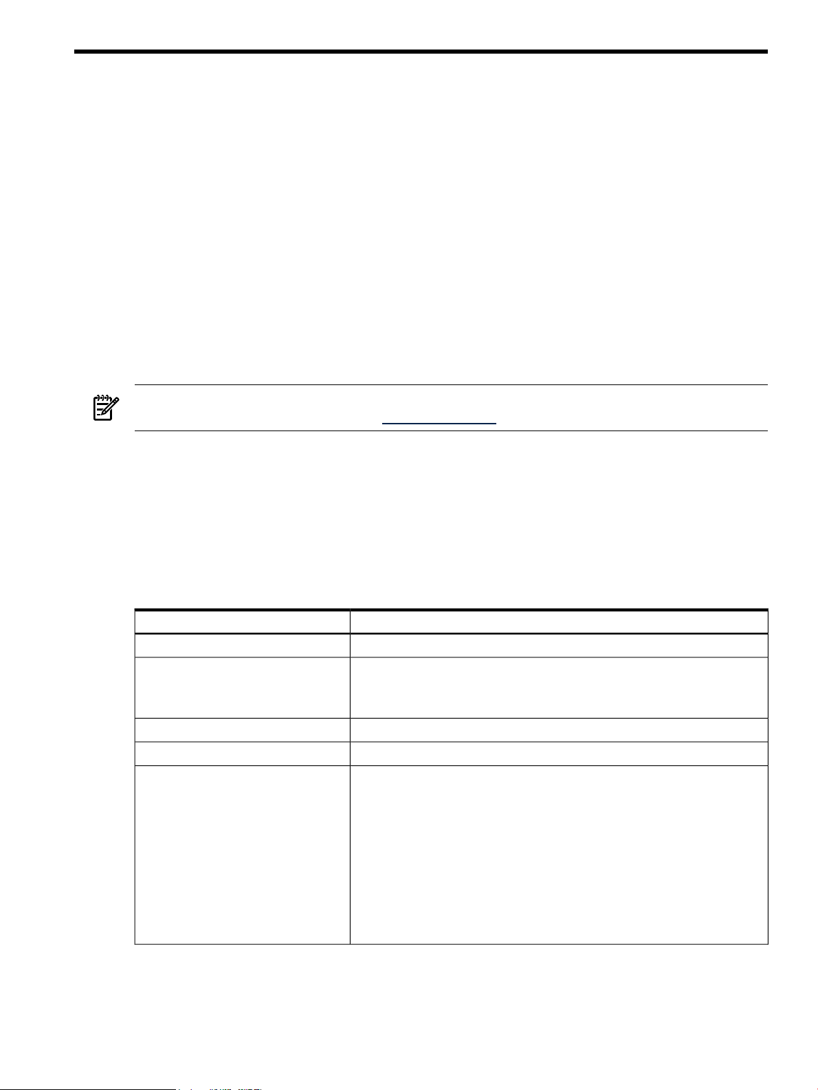
3 Typographic Conventions
This document uses the following typographic conventions.
Book Title Title of a book or other document.
Linked Title Title that is a hyperlink to a book or other document.
http://www.hp.com A Web site address that is a hyperlink to the site.
Command
user input
computer output
Enter The name of a keyboard key. Note that Return and Enter both refer to the same
term Defined use of an important word or phrase.
variable The name of an environment variable, for example PATH or errno.
value
find(1) HP-UX manpage. In this example, “find” is the manpage name and “1” is the
NOTE: Examples captured from software can display software versions that differ from the actual
released product.
Command name or qualified command phrase.
Commands and other text that you type.
Text displayed by the computer.
key. A sequence such as Ctrl+A indicates that you must hold down the key labeled
Ctrl while pressing the A key.
A value that you may replace in a command or function, or information in a display
that represents several possible values.
manpage section.
4 Product Naming Conventions
Table 1 defines the naming conventions for the versions of the HP-UX operating system.
1 Intended Audience 11
Page 12

Table 1 HP-UX Versions
Table 2 defines the naming conventions for the versions of the Integrity VM product.
Table 2 Integrity VM Versions
5 Document Organization
This manual consists of the following chapters:
• “Introduction” (page 15) describes the concept of the virtual machine as it applies to Integrity VM.
• “Installing Integrity VM” (page 21) describes how to install the Integrity VM product.
• “Creating Virtual Machines” (page 27) describes how to create virtual machines.
• “Creating HP-UX Guests” (page 41) describes how to create HP-UX guests
• “Creating Windows Guests” (page 47) describes how to create Windows® guests.
• “Creating Virtual Storage Devices” (page 61) describes how to create virtual storage devices.
• “Creating Virtual Networks” (page 89) describes how to create virtual networks.
• “Managing Guests” (page 101) describes how to start, stop, and manage virtual machines.
• “Migrating Virtual Machines” (page 111) describes how to migrate guests to other VM Host systems.
• “Using HP Serviceguard with Integrity VM” (page 115) describes how to set up Serviceguard to
manage your guests.
• “Reporting Problems with Integrity VM” (page 129) describes how to solve virtual machine problems.
• “Integrity VM Manpages” (page 133) lists the HP-UX manpages provided with the HP Integrity VM
software.
• The “Glossary” (page 181) defines many of the terms used in the Integrity VM documentation.
Version NameVersion Number
HP-UX 11.23HP-UX 11i V2
HP-UX 11i V2 May 2005 releaseHP-UX 11i V2 (0505)
HP-UX 11i V2 September 2006 releaseHP-UX 11i V2 (0609)
HP-UX 11.31HP-UX 11i V3
Version NameVersion Number
HP Integrity Virtual Machines version 1.2Integrity VM A.01.20
HP Integrity Virtual Machines version 2.0Integrity VM A.02.00
6 Related Information
You candownload thelatest version ofthis documentfrom docs.hp.com.The followingrelated documents
can also be downloaded from the same site:
• HP Integrity Virtual Machines Release Notes
• Ignite-UX Reference
• Troubleshooting Ignite-UX Installation Booting White Paper
• HP-UX Installation and Update Guide
• HP-UX Reference
• Managing Serviceguard
• Windows on Integrity: Smart Setup Guide
• HP Auto Port Aggregation (APA) Support Guide
• Using HP-UX VLANS
The web site docs.hp.com also includes technical papers about using virtual machines.
For a time-limited evaluation version of Integrity VM, search software.hp.com.
12 About This Document
Page 13

7 Publishing History
Manufacturing Part
Number
Systems
8 HP Encourages Your Comments
HP encourages your comments concerning this document. We are truly committed to providing
documentation that meets your needs.
Your comments and suggestions regarding product features will help us develop future versions of the
Virtual Server Environment Management Software. Use the following e-mail address to send feedback
directly to the VSE Management Software development team: vse@hpuxweb.fc.hp.com.
NOTE: HP cannot provide product support through this e-mail address. To obtain product support,
contact your HP Support representative, your HP Services representative, or your authorized HP reseller.
For more information about support services, see the support web site at http://www.hp.com/go/support.
For other ways to contact HP, see the Contact HP web site at http://welcome.hp.com/country/us/en/
contact_us.html.
Publication DateEdition NumberSupported VersionsSupported Operating
October 20051.011i v2HP-UXT2767-90004
October 20062.011i v2HP-UXT2767-90024
7 Publishing History 13
Page 14

14
Page 15
1 Introduction
PowerRun Attn. Fault Remote
HP-UX
Server
Windows
Server
HP-UX
Guest
Windows
Guest
VM Host
Boot Disk
HP-UX
Boot Disk
Windows
Boot Disk
HP-UX
Guest
Storage
HP Integrity Server
Virtual
Disk
Virtual
Disk
Virtual
Disk
Virtual
DVD
DVD
Removable
Media
This chapter describes the Integrity Virtual Machines product, including:
• “About HP Integrity Virtual Machines” (page 15)
• “Running Applications in the Integrity VM Environment” (page 16)
• “Related Products” (page 17)
• “Using This Manual” (page 18)
• “Using the Integrity VM Documentation” (page 18)
• “Help Files” (page 19)
1.1 About HP Integrity Virtual Machines
Integrity Virtual Machines is a soft partitioning and virtualization technology that provides operating
system isolation, with sub-CPU allocation granularity and shared I/O. Integrity VM can be installed on
an Integrity server or hardware partition (nPartition) running HP-UX. The Integrity VM environment
consists of two types of components:
• VM Host
• Virtual machines (also called guests)
The VM Host virtualizes physical processors, memory, and I/O devices, allowing you to allocate them as
virtual resources to each virtual machine.
Virtual machines are abstractions of real, physical machines. The guest operating system runs on the
virtual machine just as it would run on a physical Integrity server, with no special modification. Integrity
VM provides a small guest software package that aids in local management of the guest's virtual machine.
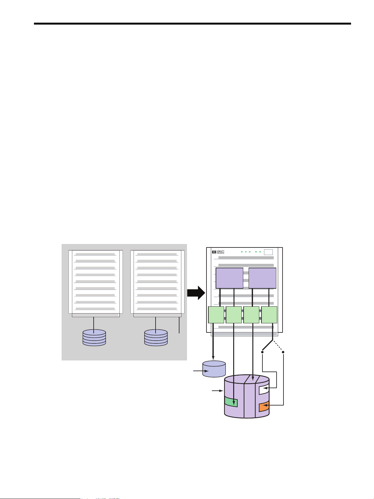
Figure 1-1 Hardware Consolidation using Integrity VM
Guests are fully loaded, operational systems, completewith operating system, system managementutilities,
applications, and networks, all running in the virtual machine environment that you set up for them. You
boot and manage guests using the samestorage media and procedures that you would if the guest operating
system were running on its own dedicated physical hardware platform. Even the system administration
privileges can be allocated to specific virtual machine administrators.
1.1 About HP Integrity Virtual Machines 15
Page 16

One way to benefit from Integrity VM is to run multiple virtual machines on the same physical machine.
There is no set limit to the number of virtual machines that can be configured, but no more than 256 virtual
machines can be booted simultaneously on a single VM Host. Each virtual machine is isolated from the
others. The VM Host administrator allocates virtual resources to the guest. The guest accesses the number
of CPUs that the VM Host administrator allocates to it. CPU use is governed by an entitlement system
that you can adjust to maximize CPU use and improve performance. A symmetric multiprocessing system
can run on the virtual machine if the VM Host system has sufficient physical CPUs for it. Figure 1-1
illustrates how an HP-UX system and a Windows system can be consolidated on a single Integrity server.
The HP-UX boot disk is consolidated onto the same storage device as the VM Host boot disk and the
Windows guest storage. The Windows guest also has access to removable media (CD/DVD) that can be
redefined as necessary.
Because multiple virtual machines share the same physical resources, I/O devices can be allocated to
multiple guests, maximizing use of the I/O devices and reducing the maintenance costs of the data center.
By consolidating systems onto one platform, your data center requires less hardware and management
resources.
Another use for virtual machines is to duplicate operating environments easily, maintaining isolation on
each virtual machine while managing them from a single, central console. Integrity VM allows you to
create and clone virtual machines with a simple command interface. You can modify existing guests and
arrange networks that provide communication through the VM Host's network interface or the guest local
network (localnet). Because all the guests share the same physical resources, you can be assured of identical
configurations, including the hardware devices backing each guest's virtual devices. Testing upgraded
software and system modifications is a simple matter of entering a few commands to create, monitor, and
remove virtual machines.
Integrity VM can improve the availability and capacity of your data center. Virtual machines can be used
to run isolated environments that support differentapplications on the same physicalhardware. Application
failures and system events on one virtual machine do not affect the other virtual machines. I/O devices
allocated to multiple virtual machines allow more users per device, enabling the data center to support
more users and applications on fewer expensive hardware platforms and devices.
1.2 Running Applications in the Integrity VM Environment
The VM Host system runs the Integrity VM software, which is responsible for allocating processor and
memory resources to the running guests. The VM Host system can run physical resource, performance,
and software management and monitoring tools. To allow the VM Host to allocate resources to the virtual
machines, do not run end-user applications, such as database software, on the VM Host system. Instead,
run them on virtual machines.
Typical software you can run on the VM Host includes the following:
• HP-UX Foundation Operating Environment (FOE)
NOTE: The HP-UX FOE and license is included with the Integrity VM media so that you can install
and run Integrity VM on the VM Host system. For HP-UX guests, you must purchase FOE licenses.
• Software installation tools (Ignite-UX and Software Distributor-UX)
• Hardware diagnostic and support toolsto monitor guests (WBEM, online diagnostics, Instant Support
Enterprise Edition [ISEE])
• System performance monitoring tools (GlancePlus, Measureware, OpenView Operations Agent)
• Utility pricing tools (Instant Capacity, Pay per use)
• Hardware management tools (nPartition Manager, storage and network management tools)
• Multipath storage solutions
Do not run the following types of software on the VM Host system:
• vPars (Virtual Partitions and virtual machines are mutually exclusive.)
• Workload Manager (WLM)
A guest running on a virtual machine runs the way it does on a physical system. By allocating virtual
resources, you provide the guest operating system and applications with access to memory, CPUs, network
devices, and storage devices as if they were part of a dedicated system.
16 Introduction
Page 17

Typical software you can run on a guest includes the following:
• HP-UX Foundation Operating Environment (FOE)
• Windows 2003 for Integrity Servers (Enterprise edition)
• Software installation tools (Ignite-UX and Software Distributor-UX)
• System performance monitoring tools (GlancePlus, Measureware, OpenView Operations Agent)
Applications do not have to be changed to run on a guest OS. Operating system patches and hardware
restrictions apply to guests.
Do not run the following types of applications on a guest:
• Integrity VM software
• Hardware diagnostic tools and support tools (should be run on the VM Host)
• Utility pricing tools (run on the VM Host)
• Capacity planning tools (run on the VM Host)
• Applicationsthat require direct access to physical hardware (for example, disaster-tolerant solutions)
• Multipath storage solutions
• SAN Management tools and applications that require access to serial interfaces (Integrity VM
virtualizes SCSI and Ethernet devices only)
• Auto port aggregation (APA)
You must purchase licenses for any software you run on a virtual machine, including the HP-UX operating
system and any HP or third-party layered software. You can purchase the licenses for HP software under
the HP Virtualization Licensing program. For more information, contact your HP Support representative.
You can install the VM Host on a system that is running HP-UX 11i v2 May 2005 or later. Guests must
also be running HP-UX 11i v2 May 2005 or later. Always read the product release notes before installing
any software product so that you have the latest information about changes and additions to the
documentation. The following chapters describe how to install the Integrity VM software and how to
create guests to run on the VM Host system.
1.3 Related Products
Some of the HP products that you can use with Integrity VM include:
• HP Integrity VM Manager — A graphical user interface for creating and managing HP Integrity
virtual machines. Runs under either HP System Management Homepage (SMH) or HP Systems
Insight Manager as part of the HP Integrity VSE. For more information, see the Getting Started with
Integrity Virtual Machine Manager guide.
• HP Integrity Virtual Server Environment (VSE) — A graphical user interface for managing HP Integrity
central managed systems (CMS). Runs under HP Systems Insight Manager. For more information,
see the HP VSE Management Software Quick Start Guide.
• HP-UX operating system — Integrity VM runs on HP-UX 11i v2 Integrity systems. For more
information, see the HP-UX 11i v2 Installation and Update Guide.
• HPIntegrity Support Pack and Microsoft® Windows®Server 2003 Service Pack 1 — HP recommends
that you install the Support Pack and SP1 on all HP Integrity servers running Windows Server 2003,
64-bit.. For more information, see the HP Integrity Support Pack and Microsoft Windows Server 2003
Service Pack 1 Release Notes.
• VERITAS Volume Manager— A data storage solution product that can be used to manage the physical
disks on the VM Host. For more information, see the VERITAS Volume Manager Administrator's Guide.
• HP Auto Port Aggregation (APA) — A network switch that allows you to manage multiple network
interfaces, which can be allocated to guests. For more information, see the HP Auto Port Aggregation
(APA) Support Guide
• HP Integrity Virtual Machines VMMigrate utility — Anoptional, separately-installed software package
that allows you to move virtual machines from one VM Host to another. For more information, see
“Migrating Virtual Machines” (page 111) in this manual.
1.3 Related Products 17
Page 18

• HP Serviceguard — A software product that allows you to create clusters of HP-UX systems for high
availability. For moreinformation, see the Managing Serviceguard manual, and “UsingHP Serviceguard
with Integrity VM” (page 115), in this manual.
• HP Integrity Essentials Global Workload Manager (gWLM) — A software product that allows you
to centrally define resource-sharing policies that you can use across multiple Integrity servers. These
policies increase system utilization and facilitate controlled sharing of system resources.
1.4 Using This Manual
This manual provides all the information you need to install Integrity VM, create virtual machines, install
and manage guests, and use all the features of Integrity VM. Table 1-1 describes each chapter in this
manual.
Table 1-1 Chapters of this Manual
Read if...Chapter
You are new to HP Integrity Virtual Machines.“Introduction” (page 15)
You are installing the HP Integrity Virtual Machines product.“Installing Integrity VM” (page 21)
“Creating Virtual Machines” (page 27)
“Creating HP-UX Guests” (page 41)
“Creating Windows Guests” (page 47)
“Creating Virtual Storage Devices” (page 61)
“Creating Virtual Networks” (page 89)
“Migrating Virtual Machines” (page 111)
“Using HP Serviceguard with Integrity VM” (page 115)
“Glossary” (page 181)
You are setting up new virtual machines on your VM Host
system.
You are creating virtual machines that will run the HP-UX
operating system.
You are creating virtual machines that will run the HP Integrity
Windows 2003 Enterprise operating system.
You need to make changes to the storage devices used by the
VM Host or virtual machines.
You need to make changes to the network devices on the VM
Host systemor to the virtual networkdevices used by the virtual
machines.
You need to manage existing virtual machines.“Managing Guests” (page 101)
You need to move virtual machines from one VM Host system
to another.
Youneed to set up Serviceguard to manage your VMHost system
or your virtual machines.
Youencounter problems while creating or using virtual machines.“Reporting Problems with Integrity VM” (page 129)
You need to understand how to use an Integrity VM command.“Integrity VM Manpages” (page 133)
You do not understand the definition of a term used in the
Integrity VM product documentation.
1.5 Using the Integrity VM Documentation
The Integrity VM product includes several useful sources of information, whether you are considering
how to set up your virtual machines or determining how to upgrade your installation.
1.5.1 Integrity VM Manpages
For online information about using Integrity VM, refer to the following manpages:
• hpvm(5) - describes the Integrity VM environment.
• hpvmclone(1M) - describes how to create virtual machines based on existing virtual machines.
• hpvmcollect(1M) - describes how to collect virtual machine statistics.
• hpvmconsole(1M) - describes how to use the virtual machine console.
• hpvmcreate(1M) - describes how to create virtual machines.
• hpvmdevmgmt(1M) - describes how to modify the way virtual devices are handled.
• hpvminfo(1M) - describes how to get information about the VM Host.
• hpvmmigrate(1M) - describes how to migrate virtual machines from one VM Host to another.
18 Introduction
Page 19

• hpvmmodify(1M) - describes how to modify virtual machines.
• hpvmnet(1M) - describes how to create and modify virtual networks.
• hpvmstart(1M) - describes how to start virtual machines.
• hpvmstatus(1M), - describes how to get statistics about the guests.
• hpvmstop(1M) - describes how to stop a virtual machine.
• hpvmremove(1M) - describes how to remove a virtual machine.
• hpvmresources(1M) - describes how to specify the storage and network devices used by virtual machines.
1.5.2 Help Files
The virtual machine console is a special interface for managing guests. To start the virtual console after
you create a guest, enter the hpvmconsole command and specify the guest name. For help using the
virtual console, enter the HE command. For more information about the virtual console, see “Using the
Virtual Console” (page 105).
1.5 Using the Integrity VM Documentation 19
Page 20

20
Page 21
2 Installing Integrity VM
This chapter describes how to install the Integrity VM software and how to prepare the VM Host
environment for guests. It includes the following sections:
• “Installation Requirements” (page 21)
• “Installation Procedure” (page 22)
• “Upgrading from Earlier Versions of Integrity VM” (page 23)
• “Verifying the Installation of Integrity VM” (page 24)
• “Removing Integrity VM” (page 24)
• “Reserving VM Host Devices” (page 24)
• “Troubleshooting Installation Problems” (page 25)
2.1 Installation Requirements
To prepare your VM Host system for Integrity VM installation, your configuration must satisfy the
hardware, software, and network requirements described in this section. To install Integrity VM, you need
a computer that fits the specifications listed in “VM Host System Requirements” (page 21).
NOTE: Before installing this product, read the HP Integrity Virtual Machine Release Notes. The most
up-to-date release notes are available on http://docs.hp.com.
2.1.1 VM Host System Requirements
The resourceson the VM Host system (such as disks, network bandwidth, memory, and processing power,
are shared by the VM Host and all the running guests. Guests running simultaneously share the remaining
memory and processing power. By default, network and storage devices are also sharable among guests.
Some resources must be made exclusive to the VM Host, such as the VM Host operating system boot disk.
Table 2-1 describes the minimum configuration requirements for installing Integrity VM on the VM Host
system.
Table 2-1 Requirements for Installing Integrity VM
DescriptionResource
An Integrity serverComputer
Operating system
Disk storage
HP-UX 11i v2 May 2005 or later, running on an Integrity server, as well as any
appropriate software patches (see the HP Integrity Virtual Machines Release Notes). The
license for Integrity VM includes the license for running the HP-UX Foundation
Operating Environment on the VM Host system.
Required for network connection and configuration.Local area network (LAN) card
An appropriate source for installing software (DVD or network connection).Source installation media
Sufficient disk space for the following:
• The VM Host operating system (refer to the HP-UX 11i v2 Installation and Upgrade
Guide)
• The VM Host software (50 MB)
• Swap space size should be at least as large as physical memory plus 4GB (for
example, for 16 GB of RAM, swap space should be 20 GB)
NOTE: HP-UX uses this space to start up guests, but guests are never swapped
out.
• Disk space for each guest operating system, including swap space
• Disk space for the applications running on each guest
• 4.7 MB for each running guest as the allowance for backing up configuration files
2.1 Installation Requirements 21
Page 22

Memory
Table 2-1 Requirements for Installing Integrity VM (continued)
DescriptionResource
Sufficient physical memory (RAM), including the following:
• 750 MB + 7.5% of memory beyond the first GB (that is, 7.5% of (total physical
memory - 1 GB))
• Total aggregate memoryrequired foreach guest(operating systemand application
requirements)
HP-UX 11i v2 May 2005 requires a minimum of 1 GB of memory, so a guest running
HP-UX must be configured with at least that much memory.
• Additional 7% of aggregate guest memory for overhead
For example, for a VM Host with 16 GB of memory and two VMs configured with
3GB of memory each, the memory requirements would be calculated as follows:
• 1.86 GB for the VM Host (750 MB plus 7.5% of 15 GB)
• 6.42 GB total guest requirement (107% of 6 GB)
• Total requirements = 8.28 GB of memory
This leaves 7.72 GB of memory for additional guests.
Integrity VM software
Network configuration
The software bundle T2767AC. Refer to “Bundle Names” (page 22) for information
about the required software for installing Integrity VM.
A configured and operational network, with at least one LAN card if you plan to allow
remote access to guest virtual consoles. To allow guests network access, the VM Host
must haveat leastone functioning network interfacecard (NIC).For more information
about configuring network devices for virtual machines, see “Creating Virtual
Networks” (page 89).
2.1.2 Bundle Names
Integrity VM software is bundled as T2767AC, which includes VMAGENT, the Integrity VM fair-share
scheduler. When you install Integrity VM, the following software bundles are installed:
• T2767AC
• PRM-Sw-Krn (included with T2767AC)
• VMGuestLib
In addition to the T2767AC bundle, you can install the following optional software bundles:
• VMProvider (to use the HP Integrity VM Manager to manage the VM Host)
• VMMigrate (to be able to migrate virtual machines from one VM Host to another). For information
about using the hpvmmigrate command, see “Migrating Virtual Machines” (page 111).
2.1.3 Using VM Manager Requires the Latest WBEM Services on the VM Host
The version of HP WBEM Services for HP-UX must be A.02.00.10 or later. Integrity VM fails to install if
the version of WBEM Services on your VM Host is older than A.02.00.10. The HP WBEM Services for
HP-UX software bundle (B8465BA) is available as part of the HP-UX 11i V2 0606 (June 2006) operating
system and later. For VM Hosts running earlier versions of HP-UX, download the latest version of WBEM
Services from www.hp.com.
2.2 Installation Procedure
Once you have read the product release notes and verified that you have met the proper system
requirements as described in “VM Host System Requirements” (page 21), install the Integrity VM software
as described in this section.
NOTE: Installing the Integrity VM software mayrequire the system to reboot. Therefore, the swinstall
command line installation includes the autoreboot=true parameter.
To install the HP Integrity VM software, follow these steps:
22 Installing Integrity VM
Page 23

1. If you have the installation media, mount it.
If you are installing from the network, identify the VM Host and pathname that correspond to the
software distribution depot that contains the T2767AC bundle (for example,
my.server.foo.com:/depot/path).
2. Use the swinstall command to install Integrity VM and specify the path to the depot. For example:
# swinstall -x autoreboot=true -s my.server.foo.com:/depot/path T2767AC
If you are using the GUI (swinstall i), perform the following steps:
a. Enter the following commands:
# export DISPLAY=your display variable
# swinstall
b. Select the Integrity VM bundle (T2767AC) from the list presented by the GUI.
The VM Host and guest configuration files are stored at /var/opt/hpvm. The new configuration
files are not compatible with those of previous versions of Integrity VM.Therefore, if you are upgrading
to the current version, the guest configuration files (except the /ISO-Images/ directory) are saved
to the /var/opt/hpvm_backup directory. If you revert to the older version of Integrity VM, you
can use the backup configuration files to restore your VM Host and guest configurations.
3. Unmount and remove any installation media. The VM Host system automatically reboots, if necessary.
4. Once the Integrity VMsoftware is installed and running, the VM Host is available. Enter the following
command to get information about the status of the guests:
# hpvmstatus
hpvmstatus: No guest information is available.
hpvmstatus: Unable to continue.
The installation is now complete, with the following results:
• Integrity VM is installed in the /var/opt/hpvm directory.
• Integrity VM data files are installed under the /var/opt/hpvm directory.
• Integrity VM commands are installed in the /opt/hpvm/bin directory.
• Integrity VM installation modifies certain kernel parameters. If you use multiple shells to manage
Integrity VM, change the kernel parameters on all your shells. Table 7-1 lists the kernel parameters
that are modified when you install Integrity VM.
Table 2-2 Kernel Parameters
dbc_max_pct
dbc_min_pct
maxdsiz_64bit
swapmem_on
You can now create guests using the hpvmcreate command, as described in Chapter 3 (page 27).
2.3 Upgrading from Earlier Versions of Integrity VM
When you upgrade Integrity VM from an earlier version, you should:
1. Shut down all running guests (using the hpvmstop command).
2. Locate and install the new version of Integrity VM.
3. Install new versions of the vmmigrate utility and the VMProvider, if they were previously installed.
4. Reboot the VM Host system.
Modified ValueDefault ValueParameter
150
15
343597383684294967296
01
2.3 Upgrading from Earlier Versions of Integrity VM 23
Page 24

Existing guest configuration information, operating system software,and application data are not affected
when you upgrade Integrity VM.
If you have installed an evaluation version of Integrity VM, you should remove the evaluation software
before installing the Integrity VM product. For more information, refer to the Integrity VM Release Notes.
2.4 Verifying the Installation of Integrity VM
To verify that Integrity VM installed successfully, enter the following hpvminfo command:
# hpvminfo
hpvminfo: Running on an HPVM host.
To see exactly what versions of specific bundles are installed, enter the swlist command:
# swlist T2767AC
# Initializing...
# Contacting target "gaggle"...
#
# Target: gaggle:/
#
# T2767AC A.02.00.02 Integrity VM
T2767AC.HPVM A.02.00.02 Integrity VM HPVM
T2767AC.VMAGENT A.02.00.02 HP Resource Allocation Agent for Integrity
VM
NOTE: Specific baselevels on your installation might not exactly match the examples in this manual. For
example, you may see A.02.00.01 or A.02.00.02.
When you install Integrity VM, the file /etc/rc.config.d/hpvmconf is created to record the product
configuration.
2.5 Removing Integrity VM
To remove the Integrity VM product, you must remove the following software bundles:
• VMProvider (if installed)
• T2767AC
• VMGuestLib
• VMMigrate (if installed)
• VMKernelSW (reboots the system)
To remove these bundles, enter the following commands:
# swremove VMProvider
# swremove T2767AC
# swremove VMGuestLib
# swremove VMMigrate
# swremove -x autoreboot=true VMKernelSW
# rm -rf /opt/hpvmprovider
# rm -rf /opt/hpvm
Guests are not affected by this procedure. To remove guests, see the procedures in “Removing Virtual
Machines” (page 38).
2.6 Reserving VM Host Devices
You can protect the storage and network resources used by the VM Host against usage and corruption by
virtual machines by marking the VM Host devices as restricted devices. For example, you can reserve the
disk storage on which the VM Host operating system and swap space reside, which prevents guests from
24 Installing Integrity VM
Page 25

being able to access the same disk storage devices. The hpvmdevmgmt command allows you to establish
restricted devices.
For example, to restrict the /dev/rscsi/c2t0d0 device, enter the following command:
# hpvmdevmgmt –a rdev:/dev/rscsi/c2t0d0
To complete the restriction of volumes, each device included in the volume must also be restricted. For
more informationabout using the hpvmdevmgmt command, see “Managing the DeviceDatabase” (page 107).
2.7 Troubleshooting Installation Problems
If the installation verification fails, report the problem using the procedures described in “Reporting
Problems with Integrity VM” (page 129). Some problems encountered in the process of installing Integrity
VM are described in the following sections.
2.7.1 Error messages during installation
One or more of the following messages might be displayed during Integrity VM installation:
could not write monParams: Device is busy
hpvmnet * already exists
/sbin/init.d/hpvm start ran without running /sbin/init.d/hpvm stop
You can ignore these messages.
2.7 Troubleshooting Installation Problems 25
Page 26

26
Page 27

3 Creating Virtual Machines
After you install Integrity VM, you can begin to create guests. This chapter includes the following sections:
• “Specifying Virtual Machine Characteristics” (page 27)
• “Using the hpvmcreate Command” (page 31)
• “Starting Virtual Machines” (page 33)
• “Changing Virtual Machine Configurations” (page 34)
• “Cloning Virtual Machines” (page 37)
• “Stopping Virtual Machines” (page 37)
• “Removing Virtual Machines” (page 38)
• “Troubleshooting Virtual Machine Creation Problems” (page 39)
3.1 Specifying Virtual Machine Characteristics
When you create a new virtual machine, you specify its characteristics. Later, you can change the virtual
machine characteristics. The characteristics of a virtual machine are listed in Table 3–1.
You can create a virtual machine using the following commands:
• hpvmcreate
• hpvmclone
After you create a virtual machine, you can modify it using the the hpvmmodify command. All of these
commands accept the same options for specifying virtual machine characteristics. Each option and
characteristic is described in more detail later in this chapter.
Table 3-1 Characteristics of an Integrity Virtual Machine
-P vm-name
-O os_type
-c number_vcpus
-e percent
-E cycles
-r amount
-a rsrc
3.1.1 Virtual Machine Name
Use the-p vm-name option tothe hpvmcreate command to specify the name of the new virtual machine.
This option is required. In the following example, the new virtual machine is named compass1:
# hpvmcreate -P compass1
Where DescribedVirtual Machine CharacteristicCommand Option
“Virtual Machine Name” (page 27)Virtual machine name. You must specify a
name when you create or modify the virtual
machine. You cannot modify this
characteristic.
“Guest Operating System” (page 28)Operating system. If you do not specify the
operating system type, it is set to
UNKNOWN.
“Virtual CPUs” (page 28)Virtual CPUs (vCPUs). If you omit this
option when you create the virtual machine,
the default is one vCPU.
“Entitlement” (page 28)CPU entitlement. If you omit this option
when you create the virtual machine, the
default is 10%.
“Guest Memory Allocation” (page 29)Memory. If you omit this option when you
create the virtual machine, the default is 2
GB.
“Virtual Devices” (page 29)Virtual devices.If you omit thisoption when
you create the virtual machine, it has access
to no network and storage devices.
The virtual machine name can be up to 256 alphanumeric characters. To provide remote console access to
the guest, its name must be a legal UNIX account name (no more than eight characters, where the colon
(:) and newline (\) characters are not valid). See password(1M) for more information about HP-UX account
3.1 Specifying Virtual Machine Characteristics 27
Page 28

names. For more information about setting up remote console access to the guest, see “Using the Virtual
Console” (page 105).
3.1.2 Guest Operating System
Use the -o os_type option to the hpvmcreate command to specify the type of operating system that
will run on the virtual machine. This option is not required.
For os_type, specify one of the following:
• hpux
• windows
If you do not supply the operating system type, it defaults to UNKNOWN. When you install the operating
system, this value in the guest configuration file is automatically set to the appropriate operating system
type.
In the following example, the virtual machine compass1 is specified as an HP-UX guest:
# hpvmcreate -P compass1 -o hpux
For more information about creating HP-UX guests, refer to Chapter 4 (page 41).
For more information about creating Windows guests, refer to Chapter 5 (page 47).
When a running guest transitions from running in the machine console to running in the operating system,
the operating system type is detected. If the operating system type is different from the information in the
guest's configuration file, it is automatically updated to reflect the current operating system.
3.1.3 Virtual CPUs
Use the -c number_vcpus option to the hpvmcreate command to specify the number of virtual CPUs
(vCPUs) that the virtual machine can use. If you do not specify the number of vCPUs, the default is 1. For
example, to set the new virtual machine compass1 to have two vCPUs, enter the following command:
# hpvmcreate -P compass1 -c 2
Every virtual machine has at least one vCPU. A virtual machine cannot use more than vCPUs than the
number of physical CPUs on the VM Host system. (For the purpose of this discussion, the term “physical
CPU” refers to a processing entity on which a software thread can be scheduled.)
Integrity VM allows you to create a virtual machine with more vCPUs than the number of physical CPUs
on the VM Host system. Warning messages are dislayed if there are not enough physical CPUs to run the
virtual machine. This feature allows you to create virtual machines for future configurations. However,
the virtual machine is not allowed to start on a VM Host system that does not have enough physical CPUs.
3.1.4 Entitlement
Use the -e or -E option to specify the virtual machine's entitlement.
Virtual machine entitlement is the minimum amount of processingpower guaranteedto the virtual machine
from each virtual CPU. When you create a virtual machine, you can use the -e option to specify the
entitlement as a percentage, from 5% to 100%. If you do not specify the entitlement, the virtual machine
receives 10% entitlement by default.
Alternatively, you can use the -E option to specify the entitlement as the number of CPU clock cycles per
second to be guaranteed to each vCPU on the virtual machine.
For example, to specify an entitlement of 20% for the new virtual machine compass1, enter the following
command:
# hpvmcreate -P compass1 -e 20
When the virtual machine is booted, the VM Host ensures that sufficient processing power is available
for each running virtual machine to receive its entitlement. For virtual machines with multiple virtual
CPUs, the entitlement is guaranteed on all the vCPUs in the virtual machine's configuration. For example,
if a virtual machine has four vCPUs, and the entitlement is set at 12%, the VM Host ensures that the
equivalent of at least 48% of a physical CPU's processing power is available to that virtual machine. As
28 Creating Virtual Machines
Page 29

many physical processors as the virtual machine has vCPUs can contribute to the total processing power
of the virtual machine.
To allow multiple virtual machines to run at the same time, make sure that the entitlement of each virtual
machine does not prevent the others from obtaining sufficient processor resources. The sum of all
entitlements across all active virtual machines cannot total more than 100% for any physical processor. If
available processor resources are insufficient, the virtual machine is not allowed to boot; error messages
are displayed to indicate the specific problem.
If a virtual machine is busy and sufficient processing power is available on thehost system, the virtual
machine can receive more than its entitlement. When there is contention for processing power (on a VM
Host system with busy virtual machines), each virtual machine is limited to its entitlement.
3.1.5 Guest Memory Allocation
Use the -r amount option to the hpvmcreate command to specify the amount of virtual memory (in
either gigabytes or megabytes) to be allocated to the guest. If you do not specify the memory allocation,
the default is 2 GB. For example, to allocate three gigabytes to the virtual machine compass1, enter the
following command:
# hpvmcreate -P compass1 -r 3G
The amount of memory to allocate is the total of the following:
• The amount of memory required by the guest operating system. For example, the HP-UX 11i v2
operating system requires 1 GB of memory.
• The amount of memory required by the applications running on the guest.
The amount of memory should be at least the total of these two amounts. If there is not enough memory
in the current configuration, Integrity VM issues a warning but allows you to create the virtual machine.
This allows you to create virtual machines for future configurations. When the virtual machine is started,
the VM Host makes sure that there is sufficient memory to run the virtual machine. In addition to the
amount of memory you specify for the virtual machine, the VM Host requires a certain amount overhead
for booting the guest operating system. The amount of memory allocated to all the running guests cannot
exceed the amount of physical memory minus the amount used by the VM Host for its operating system
and its administrative functions. For more information about the memory requirements of the VM Host,
see “Installation Requirements” (page 21).
3.1.6 Virtual Devices
Use the -a option to the hpvmcreate command to allocate network and storage devices to the virtual
machine. The VM Host presents the devices to the virtual machine as “virtual devices.” You specify both
the physical device to allocate to the virtual machine and the virtual device name that the virtual machine
will use to access the device. The following sections provide brief instructions for creating virtual network
devices and virtual storage devices.
3.1.7 Creating Virtual Network Devices
The guest virtual network consists of:
• Virtual network interface cards (vNICs)
• Virtual switches (vswitches)
For virtual machines to communicate either with other virtual machines or outside the VM Host system,
each virtual machine's virtual network must be associated with a virtual switch (vswitch). If you start a
virtual machine without a vswitch, the virtual machine has no network communication channel. A vswitch
functions like a physical network interface card (pNIC), accepting network traffic from one or more virtual
machines and directing network traffic to an associated port. A vswitch can be associated with a VM Host
pNIC, or it can be local to the virtual machines on the VM Host and provide a dedicated network among
guests.
Integrity VM always creates a vswitch named localnet. This network is not associated with a pNIC. It
is used only for communication between the guests running on the same VM Host. The localnet vswitch
does not use a name server or router, and the VM host does not access the localnet vswitch. For more
information, see “Local Networks” (page 91).
3.1 Specifying Virtual Machine Characteristics 29
Page 30

You can create vswitches any time, before or after creating guests that access the vswitches. If you create
the virtual machine before creating the vswitch, the virtual machine is created and warning messages
display the specific problem. This allows you to create virtual machines for future configurations.
To create a vswitch, enter the hpvmnet -c command. For example:
# hpvmnet -c -S vswitch-name -n nic-id
where:
• vswitch-name is the name you assign to the vswitch.
• nic-id is the pNIC ID on the VM Host. If you omit the nic-id, the vswitch is created for the
localnet.
To start the vswitch, enter the hpvmnet -b command. For example:
# hpvmnet -b -S vswitch-name
To allocate the vswitch to the virtual machine named compass2, use the —a option to the hpvmcreate
command. For example:
# hpvmcreate -P vm-name -a network:lan:[hardware-address]:vswitch:vswitch-name
where hardware-address (optional) the vNIC PCI busnumber, device, and MAC address. This portion
of the command is optional. If you omit the specific bus, device, and MAC address information, it is
generated for you. HP recommends that you allow this information to be automatically generated. In this
case, simply omit the hardware-address value from the command line. For example:
# hpvmcreate -P -a network:lan::vswitch:vswitch-name
For more information about using the hpvmnet command, see “Creating Vswitches” (page 90).
On the guest, use standard operating commands and utilities to associate the vNIC with an IP address,
or use DHCP just as you would for a physically independent machine.
By default, vswitches are sharable; you can allocate the same vswitch to multiple virtual machines.
With Integrity VM A.02.00 and later, you can create virtual LANs (VLANs), which allow virtual machines
to communicate with other virtual machines using the same VLAN, either on the same VM Host or on
different VM Host systems. You associate the VLAN port number with a vswitch, then allocate that vswitch
to virtual machines that communicate on that VLAN. For more information about VLANs, see the manual
Using HP-UX VLANs.
For more information about creating and managing vswitches, see Chapter 7 (page 89).
3.1.8 Creating Virtual Storage Devices
When you create a virtual machine, you specify the virtual storage devices that the virtual machine uses.
Virtual storage devices are backed by physical devices on the VM Host system. The VM Host system must
have sufficient physical storage for the VM Host and for all of the virtual machines.
When you create a virtual machine with the hpvmcreate command, you can specify both the virtual
devices that the virtual machine recognizes and the physical backing stores on the VM Host system. Use
the -a option to create and allocate the virtual device to the virtual machine. For example:
# hpvmcreate -a device-type:adapter-type:[hardware-address]:storage-type:device
where:
• device-type is the type of virtual device that the virtual machine will use. This can be one of the
following:
— disk
— dvd
— tape
30 Creating Virtual Machines
Page 31

— changer
— burner
• adapter-type is always scsi.
• hardware-address (optional) specifies the virtual device PCI bus number, PCI slot number, and SCSI
target number. If you do not specify this information, it is generated automatically. HP recommends
that you allow the hardware address to be generated automatically. To omit the hardware address,
use the following format:
# hpvmcreate -a device-type:adapter-type::storage-type:device
• storage-type indicates the type of physical backing store:
— disk
— lv
— file
— null
— attach
• device is the specific physical device ID (for example, /dev/rdsk/c4t3d2). To display the device
IDs on your VM Host system, enter the ioscan command.
The physicalbacking store that you associate with a virtual device can affect the performance of the virtual
machine. Use the ioscan command to obtain information about the current device configuration on the
VM Host system, and try to distribute the workload of the virtual machines across the physical backing
stores.
When you share a physical backing storage device among virtual machines. potential conflicts are not
always obvious. For example, if you use a file in a file system on /dev/dsk/c8t2d0 as a backing store,
the raw device (/dev/rdsk/c8t2d0) cannot also be used as a backing store. For more information about
specifying virtual devices, see “Creating Virtual Storage Devices” (page 61).
Integrity VM checks the current physical configuration when you create a virtual machine using the
hpvmcreate command. If the virtual machine uses backing stores that are not available, the virtual
machine is created, and warning messages provide details. If you use the hpvmstart command to start
a virtual machine that requires physical resources that are not available on the VM Host system, the virtual
machine is not allowed to start, and error messages provide detailed information about the problem.
After you create a virtual machine, you can use the hpvmmodify command to add, remove, or modify
storage devices for the virtual machine. To add a device to an exising virtual machine, include the —a
option, the same way you would on an hpvmcreate command. For example, the following command
modifies the virtual machine named compass1, adding a virtual DVD device backed by the physical disk
device /c1t1d2. The virtual hardware address is omitted and will be generated automatically.
# hpvmmodify -P compass1 -a dvd:scsi::disk::/c1t1d2
You can modify storage devices while the virtual machine is running. It is not necessary to restart the
virtual machine; however, it may be necessary to rescan for devices on the virtual machine.
Some devices should be restricted to use by the VM Host and to each guest (for example, boot devices and
swap devices). Specify restricted devices using the hpvmdevmgmt command. For more information about
sharing and restricting devices, see “Restricting VM Host Devices” (page 109).
Any alternate boot devices should be set with the same care that you would use on a physical system. If
the primary boot device fails for any reason, a virtual machine set to autoboot attempts to boot from
devices in the specified boot order until either an option succeeds or it reaches the EFI Shell. Make sure
that any specified boot options, and the boot order, are appropriate for the guest. For more information
about the autoboot setting, see Table 3-2.
3.2 Using the hpvmcreate Command
To create a virtual machine, enter the hpvmcreate command in the following format:
hpvmcreate -P vm-name [-F | -s] [-l vm_label] [-B start_attr]
[-O os_type[:version]] [-c number_vcpus] [-e percent | -E cycles]
3.2 Using the hpvmcreate Command 31
Page 32

[-g group[:{admin|oper}]] [-u user[:{admin|oper}]]
[-a rsrc] [-r amount]
[-i {SG | -i SG_pkgname | -i GWLM | -i SG_pkgname,GWLM | -i NONE}]
[-j {0|1}]
Table 3-2 describes the options you can use with the hpvmcreate command.
Table 3-2 Options to the hpvmcreate Command
DescriptionOption
-P vm-name
Specifies the name of the virtual machine. Thevirtual machine name can be up to eight
alphanumeric characters. To provide remote console access to the guest, its name must
be a legal UNIX account name (no more than eight characters, where the colon (:) and
newline (\) characters are not valid). The -P option is required.
-F
-s
-l vm_label
-B start_attr
-O os_type[:version]
-c number_vcpus
-e percent | -E cycles
Suppresses allresource-conflict checksand associated warningmessages (forcemode).
Use force mode for troubleshooting purposes only.
Sanity checks the virtual machine configuration and returns warnings or errors, but
does not create the virtual machine.
Specifies a descriptive label for this virtual machine. The label can contain up to 256
alphanumeric characters, including A-Z, a-z, 0-9, the dash (-), the underscore character
(_), and the period (.). To include spaces, the label must be quoted (" ").
Specifies the startup behavior of the virtual machine. For start_attr, enter one of
the following keywords:
auto: Automatically starts the virtual machine when the VM Host is started.
manual: Thevirtual machineis notstarted automatically. Use thehpvmstart command
to start the virtual machine manually.
Specifies the type and version of the operating system running on the virtual machine.
The os_type parameter can have the following (case-insensitive) values:
HPUX
Windows
Specifies the number of vCPUs this virtual machine detects at boot time. If unspecified,
the number defaults to one. The maximum number of vCPUs that you can allocate to
a virtual machine is the number of physical processors on the VM Host system.
Specifies the virtual machine's CPU entitlement in CPU cycles. To specify thepercentage
of CPU power, enter the following option:
-e percent
-g group[:{admin|oper}]
-u user[:{admin|oper}]
-a rsrc
32 Creating Virtual Machines
To specify the clock cycles, enter one of the following options:
-E cyclesM (for megahertz)
-E cyclesG (for gigahertz)
Specifies a group authorization. The specified administrative level (admin or oper) is
applied to the specified user group.
Specifies a user authorization. The specified administrative level (admin or oper) is
applied to the specified user.
Creates avirtual devicefor the virtual machine. Tocreate avirtual storagedevice, enter
the rsrc as:
virtual_devicetype:scsi:[bus,device,target]:phstorage_type:physical_device
For information about forming a virtual storage device specification, see Chapter 6.
To create a virtual network device for a virtual machine, enter the rsrc as:
network:adaptertype:[bus,device,mac-addr]:vswitch:vswitch-name:portid:portnumber
For information about forming a virtual network device specification, see Chapter 7
(page 89).
Page 33

-r amount
Table 3-2 Options to the hpvmcreate Command (continued)
DescriptionOption
Specifies the amount of memory available to this virtual machine. Specify the amount
as either amountM (for megabtyes) or amountG (for gigabytes).
-i package-name
-j [0|1]
Specifies whether the virtual machine is managedby Serviceguard or gWLM (or both).
The argument is one of the following:
• SG indicates that the VM Host is a Serviceguard cluster node.
• SG_pkgname indicates that the VM Host is a Serviceguard package.
• GWLM indicates that the VM Host is managed by gWLM.
• NONE indicates there are no external managers.
Do not specify this option. This option is used internally by Integrity VM.
Specifies whether the virtual machine is a distributed guest (that is, managed by
Serviceguard and can be failed over to another cluster member). Do not specify this
option. This option is used internally by Integrity VM.
3.2.1 Example of Virtual Machine Creation
To create a virtual machine named compass1, enter the following command:
# hpvmcreate -P compass1
This command creates a virtual machine named compass1 with no network access and no allocated
storage devices. To view the characteristics of the virtual machine, enter the hpvmstatus command. For
example:
# hpvmstatus
[Virtual Machines]
Virtual Machine Name VM # OS Type State #VCPUs #Devs #Nets Memory Runsysid
==================== ===== ======= ========= ====== ===== ===== ======= ========
config1 1 HPUX Off 1 5 1 512 MB 0
config2 2 HPUX Off 1 7 1 1 GB 0
winguest1 5 WINDOWS On (OS) 1 5 1 1 GB 0
winguest2 9 WINDOWS Off 1 3 1 2 GB 0
compass1 12 UNKNOWN Off 1 0 0 2 GB 0
The compass1 virtual machine has been assigned virtual machine number 12, has been created with an
UNKNOWN operating system type, one vCPU, no storage devices, no network devices, and 2 GB of
memory. The Runsysid column indicates the VM Host that runs the virtual machine in a Serviceguard
cluster. If the virtual machine runs on the localVM Host, or if Serviceguard is not configured, the Runsysid
is zero. For more information about running virtual machines under Serviceguard, see “Using HP
Serviceguard with Integrity VM” (page 115).
3.3 Starting Virtual Machines
To start the virtual machine, enter the hpvmstart command. You can specify either the virtual machine
name or the virtual machine number (listed in the hpvmstatus display under VM #.)
The hpvmstart command syntax is:
# hpvmstart {-P vm-name | -p vm_number} [-F | -s]
Table 1–3 describes the options to the hpvmstart command.
Table 3-3 Options to the hpvmstart Command
-P vm-name
-p vm_number
DescriptionOption
Specifies the name of the virtual machine. You must include
either the —P or —p option.
Specifies the number of the virtual machine. To display the virtual
machine number, enter the hpvmstatus command.
3.3 Starting Virtual Machines 33
Page 34

-F
Table 3-3 Options to the hpvmstart Command (continued)
DescriptionOption
Forces the command to act without requiring confirmation.
-s
Checks the VM Host system resources without starting the guest.
For example, to start the new virtual machine compass1, enter the following command:
# hpvmstart -P compass1
(C) Copyright 2000 - 2006 Hewlett-Packard Development Company, L.P.
Opening minor device and creating guest machine container
Creation of VM, minor device 2
Allocating guest memory: 2048MB
allocating low RAM (0-80000000, 2048MB)
/opt/hpvm/lbin/hpvmapp (/var/opt/hpvm/uuids/8ba249f2-3399-11db-aacc-00306ef392e0
/vmm_config.current): Allocated 2147483648 bytes at 0x6000000100000000
locking memory: 0-80000000
allocating firmware RAM (ffaa0000-ffab5000, 84KB)
/opt/hpvm/lbin/hpvmapp (/var/opt/hpvm/uuids/8ba249f2-3399-11db-aacc-00306ef392e0
/vmm_config.current): Allocated 86016 bytes at 0x6000000180000000
locked SAL RAM: 00000000ffaa0000 (4KB)
locked ESI RAM: 00000000ffaa1000 (4KB)
locked PAL RAM: 00000000ffaa4000 (4KB)
locked Min Save State: 00000000ffaa5000 (1KB)
RAM alignment: 40000000
Memory base low : 6000000100000000
Memory base FW : 6000000180000000
Loading boot image
Image initial IP=102000 GP=62C000
Initialize guest memory mapping tables
Starting event polling thread
Starting thread initialization
Daemonizing....
hpvmstart: Successful start initiation of guest 'compass1'
The hpvmstatus command displays the allocation of memory and devices. After you start the virtual
machine, the hpvmstatus command displaysthe virtual machine status as On (EFI), because the virtual
machine is powered on but the guest operating system is not running. Because the operating system has
not been installed, the guest OS type is listed as UNKNOWN.
# hpvmstatus
[Virtual Machines]
Virtual Machine Name VM # OS Type State #VCPUs #Devs #Nets Memory Runsysid
==================== ===== ======= ========= ====== ===== ===== ======= ========
config1 1 HPUX Off 1 5 1 512 MB 0
config2 2 HPUX Off 1 7 1 1 GB 0
winguest1 5 WINDOWS On (OS) 1 5 1 1 GB 0
winguest2 9 WINDOWS Off 1 3 1 2 GB 0
compass1 13 UNKNOWN On (EFI) 1 0 0 2 GB 0
For more information about using the hpvmstatus command, see “Managing Guests” (page 101).
3.4 Changing Virtual Machine Configurations
You can create a virtual machine with characteristics that the VM Host cannot supply at the time of creation.
This allows you to create virtual machines to run after system configuration changes. For example, the
following command creates the virtual machine compass1 with 3 vCPUs and 4 MB of allocated memory:
# hpvmcreate -P compass1 -c 3 -r 4GB
HPVM guest compass1 configuration problems:
34 Creating Virtual Machines
Page 35

Warning 1: Guest's vcpus exceeds server's physical cpus.
Warning 2: Insufficient cpu resource for guest.
These problems may prevent HPVM guest compass1 from starting.
hpvmcreate: The creation process is continuing.
Because the VM Host is not currently configured to support the new virtual machine, warning messages
indicate the specific characteristics that are inadequate.
When you start a virtual machine, the VM Host determines whether the current system configuration can
support the virtual machine's characteristics. The ability of the system to run the virtual machine can be
affected by the other virtual machines that are currently running,because they share the physical processors
and memory. Any allocated vswitches must be started, and storage devices must be made available to the
virtual machine. If the virtual machine cannot be started, the following type of message is generated:
# hpvmstart -P compass1
HPVM guest compass1 configuration problems:
Warning 1: Insufficient free memory for guest.
Warning 2: Insufficient cpu resource for guest.
These problems may prevent HPVM guest compass1 from booting.
hpvmstart: Unable to continue.
You can either change the system configuration, or modify the virtual machine. To modifythe characteristics
of a virtual machine, use the hpvmmodify command. Table 3-4 describes the options you can use on the
hpvmmodify command.
Table 3-4 Options to the hpvmmodify Command
-P vm-name
-p vm_number
-F
-s
-N new-vm-name
-l vm_label
-B start_attr
DescriptionOption
Specifies the name of the virtual machine. The name can consist
of up to 256 alphanumericcharacters including A-Z, a-z, 0-9,the
dash (-), the underscore character (_), and the period (.). The
virtual machine name cannot start with a dash (-). You must
specify either the -P option or the —p option..
Specifies the number of the virtual machine. To determine the
virtual machine number, enter the hpvmstatus command.
Suppresses all resource conflict checks and associated warning
messages (force mode). Use force mode for troubleshooting
purposes only.
Sanity-checks the virtual machine configuration and returns
warnings or errors, but does not create the virtual machine.
Specifies a new name for the virtual machine.
Modifies the descriptive label for this virtual machine. The label
can contain up to 256 alphanumeric characters, including A-Z,
a-z, 0-9, the dash (-),the underscore character (_), and the period
(.). To include spaces, the label must be quoted (" ").
Modifies the startup behavior of the virtual machine.For
start_attr, enter one of the following:
auto: Automatically starts the virtual machine when Integrity
VM is initialized on the VM Host.
manual: The virtual machine is not started automatically. Use
the hpvmstartcommand to startthe virtual machine manually.
-O os_type[:version]
Modifies the type and version of the operating system running
on the virtual machine. The os-type can have the following
(case-insensitive) values:
HPUX
Windows
3.4 Changing Virtual Machine Configurations 35
Page 36

-c number_vcpus
Table 3-4 Options to the hpvmmodify Command (continued)
DescriptionOption
Modifies the number of virtual CPUs this virtual machine detects
at boot time. If unspecified, the number defaults to one. The
maximum number of vCPUs that you can allocate to a virtual
machine is the number of physical processors on the VM Host
system.
-e percent | -E cycles
-g group[:{admin|oper}]
-u user[:{admin|oper}]
-a rsrc
-m rsrc
-d rsrc
-r amount
Modifies the virtual machine's CPU entitlement in CPU cycles.
To specify the percentage of CPU power, enter the following
option:
-e percent
To specify the clock cycles, enter one of the following options:
-E cyclesM (for megahertz)
-E cyclesG (for gigahertz)
Specifies a group authorization. The specified administrative
level (admin or oper) is applied to the specified user group.
Specifies auser authorization. The specified administrativelevel
(admin or oper) is applied to the specified user.
Adds a virtual storage or network device to the virtual machine.
For more information, see hpvmresources(1M).
Modifies an existing I/O resource for a virtual machine. The
resource is specified as described below. You must specify the
hardware address of the device to modify. The physical device
portion of the rsrc specifies a new physical device that will
replace the one in use.
Deletes a virtual resource.
Modifies the amount of memory availableto thisvirtual machine.
Specify the amount as either amountM (for megabtyes) or
amountG (for gigabytes).
-i package-name
-j [0|1]
Specifies whether the virtual machine is managed by
Serviceguard or gWLM (or both). For the argument, specify one
or more of the following parameters:
• SG indicates that the VM Host is a Serviceguard cluster node.
• SG_pkgname indicates that the VM Host is a Serviceguard
package.
• GWLM indicates that the VM Host is managed by gWLM.
• NONE indicates there are no external managers.
For a node that is managed by both Serviceguard and gWLM,
parameters are separated with a comma. For example:
SG_compass1,gWLM. Do not specify this option. This option is
used internally by Integrity VM.
Specifies whetherthe virtualmachine isa distributedguest (that
is, managed by Serviceguard) and can be failed over to another
cluster member running Integrity VM. Do not specify this option.
This option is used internally by Integrity VM.
For example, to modify the characteristics of the problematic virtual machine compass1 to removevCPUs
and memory, enter the following command:
# hpvmmodify -P compass1 -c 1 -r 2 GB
This command changes the following characteristics of the virtual machine named compass1:
• -c 1 specifies one vCPU
• —r 2 GB specifies one GB of memory
The hpvmmodify command generated no warnings, so the VM Host system is ready to start the virtual
machine.
36 Creating Virtual Machines
Page 37

After you make the necessary modifications, use the hpvmstart command to start the virtual machine.
For example:
# hpvmstart -P compass1
(C) Copyright 2000 - 2006 Hewlett-Packard Development Company, L.P.
Initializing System Event Log
Initializing Forward Progress Log
Opening minor device and creating guest machine container
Creation of VM, minor device 2
Allocating guest memory: 2048MB
allocating low RAM (0-40000000, 2048MB)
/opt/hpvm/lbin/hpvmapp (/var/opt/hpvm/uuids/8ba249f2-3399-11db-aacc-00306ef392e0
/vmm_config.next): Allocated 1073741824 bytes at 0x6000000100000000
locking memory: 0-40000000
allocating firmware RAM (ffaa0000-ffab5000, 84KB)
/opt/hpvm/lbin/hpvmapp (/var/opt/hpvm/uuids/8ba249f2-3399-11db-aacc-00306ef392e0
/vmm_config.next): Allocated 86016 bytes at 0x6000000140000000
locked SAL RAM: 00000000ffaa0000 (4KB)
locked ESI RAM: 00000000ffaa1000 (4KB)
locked PAL RAM: 00000000ffaa4000 (4KB)
locked Min Save State: 00000000ffaa5000 (1KB)
RAM alignment: 40000000
Memory base low : 6000000100000000
Memory base FW : 6000000140000000
Loading boot image
Image initial IP=102000 GP=62C000
Initialize guest memory mapping tables
Starting event polling thread
Starting thread initialization
Daemonizing....
hpvmstart: Successful start initiation of guest 'compass1'
The virtual machine compass1 is started. Now the guest operating system must be installed. For
information aboutcreating HP-UX guests, see Chapter4 (page 41). For informationabout creating Windows
guests, see Chapter 5 (page 47).
3.5 Cloning Virtual Machines
Once you have created a guest, you can easily create an identical guest by using the hpvmclone command.
Like the hpvmcreate and hpvmmodify commands, the hpvmclone command accepts the -a option for
specifying virtual devices and network interfaces. This allows you to create new guests with similar
characteristics but different virtual resources. For more information, see hpvmclone(1M).
3.6 Stopping Virtual Machines
To stop a running virtual machine, use the hpvmstop command. You must confirm this command.
Table 3-5 describes the options to the hpvmstop command:
Table 3-5 Options to the hpvmstop Command
-P vm-name
-p vm_number
-h
DescriptionOption
Specifies the name of the virtual machine. You must include
either the -P or -p option.
Specifies the number of the virtual machine. To display the virtual
machine number, enter the hpvmstatus command.
Performs a hard stop on the virtual machine, similar to a power
failure.
-g
Performs a graceful shutdown on the virtual machine. This is
the default.
3.5 Cloning Virtual Machines 37
Page 38

-F
Table 3-5 Options to the hpvmstop Command (continued)
DescriptionOption
Forces the command to act without requiring confirmation.
-q
For example, the following command stops the virtual machine named compass1. The hpvmstatus
command shows that the virtual machine is Off.
# hpvmstop -P compass1
hpvmstop: Stop the virtual machine 'compass1'? [n]: y
# hpvmstatus
[Virtual Machines]
Virtual Machine Name VM # OS Type State #VCPUs #Devs #Nets Memory Runsysid
==================== ===== ======= ========= ====== ===== ===== ======= ========
config1 1 HPUX Off 1 5 1 512 MB 0
config2 2 HPUX Off 1 7 1 1 GB 0
winguest1 5 WINDOWS On (OS) 1 5 1 1 GB 0
winguest2 9 WINDOWS Off 1 3 1 2 GB 0
compass1 12 UNKNOWN Off 1 0 0 2 GB 0
You can also use the hpvmconsole command to force the virtual machine to shut down. However, after
you install the guest operating system, you should use the standard operating system commands and
procedures on the guest to shut it down.
3.7 Removing Virtual Machines
Quiet mode. Used for scripting purposes.
To remove a virtual machine from the VM Host, use the hpvmremove command. You must confirm this
action. Table 3-6 describes the options to the hpvmremove command.
Table 3-6 Options to the hpvmremove Command
DescriptionOption
-P vm-name
-p vm_number
-F
Specifies the name of the virtual machine. You must include
either the —P or —p option.
Specifies the number of the virtual machine. To display the virtual
machine number, enter the hpvmstatus command.
Forces the command to act without requiring confirmation.
For example, the following command removes the virtual machine named compass1. The subsequent
hpvmstatus command shows that compass1 is gone:
# hpvmremove -P compass1
hpvmremove: Remove the virtual machine 'compass1'? [n]: y
# hpvmstatus
[Virtual Machines]
Virtual Machine Name VM # OS Type State #VCPUs #Devs #Nets Memory Runsysid
==================== ===== ======= ========= ====== ===== ===== ======= ========
config1 1 HPUX Off 1 5 1 512 MB 0
config2 2 HPUX Off 1 7 1 1 GB 0
winguest1 5 WINDOWS On (OS) 1 5 1 1 GB 0
winguest2 9 WINDOWS Off 1 3 1 2 GB 0
This command removes compass1 and all its configuration files, and restores any resources allocated to
that guest to the VM Host's pool of available resources. (Any guest operating system and application data
on the VM Host storage devices are not affected.)
38 Creating Virtual Machines
Page 39

3.8 Troubleshooting Virtual Machine Creation Problems
If you encounter problems with creating virtual machines, report them through your support channel.
For information about collecting information to report the problem, see “Reporting Problems with Integrity
VM” (page 129).
The following section describes a problem that might be encountered during virtual machine creation.
3.8.1 Configuration Error on Starting the Virtual Machine
When you start the virtual machine, the following message is displayed:
Configuration error: Device does not show up in guest
If you encounter this type of problem:
1. Verify that the path name to the file-backing store is correct and that the physical storage device is
mounted.
2. Verify that the size of the physical storage device is divisible by 512 bytes (for a disk device) or 2048
(for a DVD device).
3. Modify the virtual machine using the hpvmmodify command.
3.8 Troubleshooting Virtual Machine Creation Problems 39
Page 40

40
Page 41

4 Creating HP-UX Guests
To create HP-UX guests, install the HP-UX operating system on the virtual machine. To install the HP-UX
guest operating system, follow the procedures in the following sections:
• “Installing the HP-UX Guest Operating System” (page 41)
• “Installing HP-UX Guest Management Software” (page 44)
• “Troubleshooting HP-UX Guest Creation” (page 44)
4.1 Installing the HP-UX Guest Operating System
To install the HP-UX operating system on the virtual machine, follow this procedure:
1. Start the virtual machine from the VM Host administrator account using the hpvmstart command.
For example, to start the virtual machine called compass1, enter the following command. The
hpvmstatus command shows that the vritual machine is started.
# hpvmstart -P compass
(C) Copyright 2000 - 2006 Hewlett-Packard Development Company, L.P.
Initializing System Event Log
Initializing Forward Progress Log
Opening minor device and creating guest machine container
Creation of VM, minor device 2
Allocating guest memory: 2048MB
allocating low RAM (0-40000000, 2048MB)
/opt/hpvm/lbin/hpvmapp (/var/opt/hpvm/uuids/8ba249f2-3399-11db-aacc-00306ef392e0
/vmm_config.next): Allocated 1073741824 bytes at 0x6000000100000000
locking memory: 0-40000000
allocating firmware RAM (ffaa0000-ffab5000, 84KB)
/opt/hpvm/lbin/hpvmapp (/var/opt/hpvm/uuids/8ba249f2-3399-11db-aacc-00306ef392e0
/vmm_config.next): Allocated 86016 bytes at 0x6000000140000000
locked SAL RAM: 00000000ffaa0000 (4KB)
locked ESI RAM: 00000000ffaa1000 (4KB)
locked PAL RAM: 00000000ffaa4000 (4KB)
locked Min Save State: 00000000ffaa5000 (1KB)
RAM alignment: 40000000
Memory base low : 6000000100000000
Memory base FW : 6000000140000000
Loading boot image
Image initial IP=102000 GP=62C000
Initialize guest memory mapping tables
Starting event polling thread
Starting thread initialization
Daemonizing....
hpvmstart: Successful start initiation of guest 'compass1'
# hpvmstatus
[Virtual Machines]
Virtual Machine Name VM # OS Type State #VCPUs #Devs #Nets Memory Runsysid
==================== ===== ======= ========= ====== ===== ===== ======= ========
config1 1 HPUX Off 1 5 1 512 MB 0
config2 2 HPUX Off 1 7 1 1 GB 0
winguest1 5 WINDOWS On (OS) 1 5 1 1 GB 0
winguest2 9 WINDOWS Off 1 3 1 2 GB 0
compass1 12 UNKNOWN On (EFI) 1 0 0 2 GB 0
4.1 Installing the HP-UX Guest Operating System 41
Page 42

#
2. To boot the guest from the virtual console, enter the following command:
# hpvmconsole -P compass1
vMP MAIN MENU
CO: Console
CM: Command Menu
CL: Console Log
SL: Show Event Logs
VM: Virtual Machine Menu
HE: Main Help Menu
X: Exit Connection
[compass1] vMP>
The hpvmconsole command opens the virtual machine console. From the virtual console, you can
control the virtual machine just as if it were a physical Integrity server.
3. In response to the virtual machine prompt, enter the co command:
[compass1] vMP> co
EFI Boot Manager ver 1.10 [14.62] [Build: Fri Aug 4 11:37:36 2006]
Please select a boot option
EFI Shell [Built-in]
Boot option maintenance menu
Use ^ and v to change option(s). Use Enter to select an option
4. Select Boot option maintenance menu.
EFI Boot Maintenance Manager ver 1.10 [14.62]
Main Menu. Select an Operation
Boot from a File
Add a Boot Option
Delete Boot Option(s)
Change Boot Order
Manage BootNext setting
Set Auto Boot TimeOut
Select Active Console Output Devices
Select Active Console Input Devices
Select Active Standard Error Devices
Cold Reset
42 Creating HP-UX Guests
Page 43

Exit
5. Select Add a Boot Option.
EFI Boot Maintenance Manager ver 1.10 [14.62]
Add a Boot Option. Select a Volume
Removable Media Boot [Acpi(PNP0604,0)]
Load File [Acpi(PNP0A03,0)/Pci(1|0)/Mac(763AE48F393F)]
Load File [EFI Shell [Built-in]]
Legacy Boot
Exit
To install from virtual DVD, select Removable Media Boot.
To install from the Ignite-UX server, select the entry with your MAC address. For example:
Device Path Acpi(PNP0A03,0)/Pci(1|0)/Mac(763AE48F393F)
Enter New Description: lan0boot
New BootOption Data. ASCII/Unicode strings only, with max of 240 characters
Enter BootOption Data Type [A-Ascii U-Unicode N-No BootOption] : N
Save changes to NVRAM [Y-Yes N-No]: Y
6. Exit the EFI Boot Maintenance Management screen to return to the EFI Boot Manager screen. Boot
from the new boot entry, indicated by the virtual machine's MAC address:.
EFI Boot Maintenance Manager ver 1.10 [14.62]
Add a Boot Option. Select a Volume
Removable Media Boot [Acpi(PNP0604,0)]
Load File [Acpi(PNP0A03,0)/Pci(1|0)/Mac(763AE48F393F)]
Load File [EFI Shell [Built-in]]
Legacy Boot
Exit
The installation process continues just as if the virtual machine were an Integrity server.
When the basic installation process is complete, the software is copied from the distribution media to the
guest's disk. Then the operating sytem reboots. If this reboot fails, restart it, as follows:
1. Enter the EFI shell by enter the co command at the virtual machine console prompt:
[compass1] vMP> CO
(Use Ctrl-B to return to vMP main menu.)
4.1 Installing the HP-UX Guest Operating System 43
Page 44

- - - - - - - - - - Prior Console Output - - - - - - - - - -
Shell>
2. Enter fs0:
Shell> fs0:
3. Enter hpux:
fs0\> hpux
The guest boots from fs0.
If you used a DVD to install the guest operating system, remove the virtual DVD, as follows:
1. Determine the bus, device, and target ID by entering the following command:
# hpvmstatus -P compass1
2. Delete the virtual DVD by entering the following command (substituting the correct PCI bus, slot,
and target number for 0,0,0):
# hpvmmodify -P compass1 -d dvd:scsi:0,0,0
3. If necessary, restart the guest to remove the DVD from the guest configuration.
4.2 Installing HP-UX Guest Management Software
After you install the HP-UX operating system on the virtual machine, install the Integrity VM guest
management software. The guest management software includes:
• Operating system patches to optimize virtual machine operation
• Integrity VM management tools, including hpvmcollect and hpvminfo
• The VM Provider, which allows you to use the VM Manager to manage the guest.
The guest management softwarerepository is installed on theVM Host system automatically. The following
directory contains the HP-UX guest management software:/opt/hpvm/guest-images/hpux/
The HP-UX guest management software is included in this directory. A README filecontains instructions
for installing the guest management software. Install the guest management software on every HP-UX
guest.
4.3 Troubleshooting HP-UX Guest Creation
The following section describes a problem that might occur during HP-UX guest installation.
4.3.1 The guest hangs in the EFI shell
The guest hangs in the EFI when you are starting the guest and you get the following message:
Shell> \efi\hpux\hpux
'\efi\hpux\hpux' not found
Exit status code: Invalid Parameter
The EFI boot parameters were probably not set up correctly during guest operating system installation.
Choose the correct EFI partition from which to boot. For example:
Shell> fs3:
fs3:\> hpux
44 Creating HP-UX Guests
Page 45

Installation continues from the specified partition.
4.3 Troubleshooting HP-UX Guest Creation 45
Page 46

46
Page 47

5 Creating Windows Guests
You can install HP Integrity Windows 2003 on your virtual machines. These Windows guests can be
managed like a Windows server running on an independent Integrity server or nPartition, by either the
VM Host administrator or the Windows system administrator. This chapter describes:
• “Windows Guest Requirements” (page 47)
• “Installing Windows Guests” (page 47)
• “Managing Windows Guests” (page 57)
• “Troubleshooting Windows Guest Installation” (page 60)
5.1 Windows Guest Requirements
To run Windows on a virtual machine, you must install the following on the virtual machine:
• HP Integrity Windows 2003 software media with Service Pack 1. Make sure you have the product
key, which appears on the lower section of your Certificate of Authenticity.
• Integrity VM Windows guest management software.
• Optional: For management from HP Integrity Virtual Machines Manager (VM Manager) and the HP
Virtual Server Environment (VSE), the provider utilities are available on the Windows Smart Setup
Media (SSM).
The following procedure assumes that HP Integrity Virtual Machines A.02.00 or later is installed on the
VM Host system.
To install the Windows operating system on the virtual machine, select a physical backing storage unit to
be used as the guest's boot disk. For applications requiring optimal I/O performance, HP recommends
using a whole disk or disk partition of at least 34 GB. Logical volumes and file backing stores do not
perform as well as whole disks and partitions. To determine the device file name, enter the following
command:
# ioscan -funC disk
To prepare for the installation:
• If you are installing from the host's physical CD/DVD, find the physical CD/DVD in the ioscan
output.
• If you are installing from an ISO file on the host, determine the full path name to that file.
If you are using a disk, partition, or logical volume for the backing storage unit, it should be cleaned to
reduce the chance of existing installations causing errors during this installation. For a whole disk, enter
the following command:
# dd if=/dev/zero of=/dev/rdsk/c0t0d0 bs=1024k
where /c0t0d0 is the disk device name.
For a disk partition, enter the following command:
# dd if=/dev/zero of=/dev/rdsk/c0t0d0s0 bs=1024k
where /c0t0d0s0 is the disk partition name.
If you are using a file for the backing storage, use the hpvmdevmgmt utilitity with the -S option to create
the file. The utility automatically cleans the file when it is created
The installation procedure automatically repartitions the virtual disk.
5.2 Installing Windows Guests
To install the Windows guest operating system, follow these steps:
1. Create a Windows guest. In the following example, the virtual machine name (guest name) is win1:
# hpvmcreate -P win1 -O windows -c 1 -r 2G \
-a disk:scsi::disk:/dev/rdsk/c3t2d0 \
5.1 Windows Guest Requirements 47
Page 48

-a dvd:scsi::disk:/dev/rdsk/c0t0d0 \
-a network:lan::vswitch:switch1
The hpvmcreate command createsthe /var/opt/hpvm/guests/win1/directory andcreates the
guest configuration in that directory.
2. Boot the virtual machine to the EFI menu and take control of the virtual console by entering the
following command:
# hpvmconsole -P win1 -fi -c "pc -on"
vMP MAIN MENU
CO: Console
CM: Command Menu
CL: Console Log
SL: Show Event Logs
VM: Virtual Machine Menu
HE: Main Help Menu
X: Exit Connection
[guest1] vMP> pc -on
System will be powered on.
-> System is being powered on.
Please wait for the guest start sequence to complete. Use of the attention
character can prevent the guest from running.
(C) Copyright 2000 - 2006 Hewlett-Packard Development Company, L.P.
Opening minor device and creating guest machine container
Creation of VM, minor device 1
Allocating guest memory: 2048MB
allocating low RAM (0-80000000, 2048MB)
/opt/hpvm/lbin/hpvmapp (/var/opt/hpvm/uuids/682da886-06b2-11db-a3aa-00306e4a931c
/vmm_config.current):
Allocated 2147483648 bytes at 0x6000000100000000
allocating firmware RAM (ffaa0000-ffab5000, 84KB)
/opt/hpvm/lbin/hpvmapp (/var/opt/hpvm/uuids/682da886-06b2-11db-a3aa-00306e4a931c
/vmm_config.current):
Allocated 86016 bytes at 0x6000000180000000
Loading boot image
Image initial IP=102000 GP=62A000
Initialize guest memory mapping tables
Starting event polling thread
Starting thread initialization
Daemonizing....
hpvmstart: Successful start initiation of guest 'win1'
-> Command successful.
[guest1] vMP> CO
(Use Ctrl-B to return to vMP main menu.)
Loading device drivers
48 Creating Windows Guests
Page 49

EFI Boot Manager ver 1.10 [14.62] [Build: Thu Jun 8 12:30:44 2006]
Please select a boot option
EFI Shell [Built-in]
Boot option maintenance menu
Use ^ and v to change option(s). Use Enter to select an option
Boot option maintenance menu
3. Typically, the EFI shell is automatically be selected upon startup. If not, choose EFI Shell [Built-in]
from the menu.
Loading.: EFI Shell [Built-in]
EFI Shell version 1.10 [14.62]
Device mapping table
fs0 : Acpi(PNP0A03,0)/Pci(0|0)/Scsi(Pun1,Lun0)/CDROM(Entry0)
blk0 : Acpi(PNP0A03,0)/Pci(0|0)/Scsi(Pun0,Lun0)
blk1 : Acpi(PNP0A03,0)/Pci(0|0)/Scsi(Pun1,Lun0)
blk2 : Acpi(PNP0A03,0)/Pci(0|0)/Scsi(Pun1,Lun0)/CDROM(Entry0)
Shell>
4. Connect to the CDROM file system (listed in the EFI output) by entering the name of the file system.
For example:
EFI Shell> fs0:
5. Enter the ls command to make sure you are connected to the right device (look for the setupldr.efi
file):
Fs0: ls
Now that the EFI is ready, you can install the Windows® operating system. The procedure for installing
the operating system depends on the type of media you are installing from:
• To install the Windows operating system from the reinstall kit (OPK), follow the instructions in
“Installing from HP Reinstall (OPK) Media” (page 49).
• To install from Microsoft media, follow the instructions in “Installing from Windows Media” (page 53).
5.2.1 Installing from HP Reinstall (OPK) Media
1. Start the operating system loader by entering the following command:
fs0:\> setupldr
The installation script runs. The SAC> prompt is displayed. When the EVENT message is displayed
indicating that the cmd command is available, type cmd and press Enter.
Starting BUILD ENT20K.US HP Re-install Environment. Please wait...
++++++++++++++++++++++++++++++++++++++++++++++++++++++++++++++++++++++++++++++++
Press F6 if you need to install a third party SCSI or RAID driver...
.
.
.
SAC>
EVENT: The CMD command is now available.
SAC>cmd
5.2 Installing Windows Guests 49
Page 50

The Command Prompt session was successfully launched.
SAC>
2. In response to the following prompt, press the ESC key quickly followed by the TAB key. Then press
Enter to change to the new command channel:
Press <esc> <tab> for next channel.
Press 0 to return to the SAC channel.
Use any other key to view this channel.
X:\ia64\system32>
3. At the command prompt, type txtrestore and press Enter:
X:\ia64\system32> txtrestore
This is txtrestore.cmd Batch file
Microsoft Windows [Version 5.2.3790] (C) Copyright 1985-2003 Microsoft Corp.
You are about to install Windows Server on the following drive:
Drive 0: HP Virtual Disk SCSI Disk Device (36GB) Bus Number 0, Target ID 0, LUN 0 H
Attached to SCSI Controller In Embedded Slot (PCI bus 0, device 0, function 0)
Drive Layout: Partition table style is MBR
Signature = 0C9C0C9C
WARNING: If you continue with the installation, all data, including
partition table information, on the above drive will be erased
and permanently lost.
Continue with installation (Y/N)? y
Enter y to continue using the specified device. To use a different device, enter n.
4. If you continue, the following information is displayed:
Target drives set to default.
TARGETHDD=0
TARGETPQI=1
ImageDrive=X:
ImagePath=\Images
ScriptDrive=X:
ScriptPath=\IA64\ADDINS
Support=X:\Supp
IVPQET2373ALABA.PQI
=================================================================
Note: <Ctrl/C> Will always exit.
========================== TASK MENU ============================
A - 16GB Drive Partition Size.
B - 33GB Drive Partition size.
C - Full Drive size.
Q - Exit to console.
=================================================================
Select a task by typing a letter A, B, C or Q and then press enter:
WARNING, SELECTING A, B OR C WILL ERASE THE DATA ON BOOT DRIVE.
Input : c
50 Creating Windows Guests
Page 51

Type your selection from the following list, and press Enter. HP recommends that you specify C.
In response to the following prompt, enter y:
WARNING, This could potentially wipe out important data!
Recommended: Only the boot controller and hard drive be installed.
Target Drive selected: Drive0
Target Partition Size Selected: Full Drive size
Input [Y/N] : y
5. Do not power off the system while the files are being copied to the hard drive. The restore process
displays 99% complete for a long time. At the end of the successful process, the following message
is displayed. Type Exit to reboot the system.
Re-install Total Time: 23 minutes
Re-Install Finished [OK].
To restart the system...
Type [exit] to exit from command console.
At the SAC console, type [restart].
X:\IMAGES> exit
The Command Console session is exiting.
If an error message is displayed, solve the problem that causes the error and restart the process.
At the following prompt, press ESC Tab to get the SAC prompt.
Restart the system by pressing Enter in response to the SAC prompt:
Press <esc> <tab> for next channel.
Press 0 to return to the SAC channel.
Use any other key to view this channel.
SAC> Enter
6. The virtual machine is restarted. When you are prompted for the boot option, press Enter to accept
the Windows Server 2003 option.
The SAC will become unavailable soon. The computer is shutting down.
SAC>
*** VM restarting ***
Scsi(Pun1,Lun0) HP Virtual FileDVD 0.04
Scsi(Pun1,Lun0) HP Virtual FileDVD 0.04 ( 80 MBytes/sec)
EFI version 1.10 [14.62] Build flags: Running on Intel(R) Itanium Processor EFI_DEBUG
EFI IA-64 SDV/FDK (BIOS CallBacks) [Thu Jun 8 12:30:44 2006] - HP
Cache Enabled. This image MainEntry is at address 0000000000102000
FPSWA.EFI preload successful.
FPSWA.EFI start successful.
Loading device drivers
EFI Boot Manager ver 1.10 [14.62] [Build: Thu Jun 8 12:30:44 2006]
Please select a boot option
5.2 Installing Windows Guests 51
Page 52

Windows Server 2003, Enterprise
EFI Shell [Built-in]
Boot option maintenance menu
Use ^ and v to change option(s). Use Enter to select an option
Default boot selection will be booted in 30 seconds
Starting: Windows Server 2003, Enterprise
++++++++++++++++++++++++++++++++++++++++++++++++++++++++++++++++++++++++++++++++
Starting Windows...
7. When the Windows SAC> prompt says EVENT:, the CMD command is available. Press the Escape
key and quickly press the TAB key, then press Enter to go to the following command prompt:
Computer is booting, SAC started and initialized.
Use the "ch -?" command for information about using channels.
Use the "?" command for general help.
SAC>...
EVENT: A new channel has been created. Use "ch -?" for channel help.
Channel: Unattended Setup Channel
SAC>
EVENT: The CMD command is now available.
SAC>
SAC>
END-USER LICENSE AGREEMENT FOR MICROSOFT SOFTWARE
MICROSOFT WINDOWS SERVER 2003, STANDARD EDITION WITH SERVICE PACK 1
MICROSOFT WINDOWS SERVER 2003, ENTERPRISE EDITION WITH SERVICE PACK 1
IMPORTANT-READ CAREFULLY: This end user license agreement ('EULA') is a legal
agreement between you (either an individual or a single legal entity) and the
manufacturer ('Manufacturer') of the computer system ('Server') with which you
acquired the Press F8 to accept or ESC to decline the EULA.
Press PAGE DOWN for next page.
To accept the EULA, press the Escape key, then 8, which emulates the F8 function key.
8. In response to the following prompt, enter the product key, including the dashes:
Type the Product Key below in the form
XXXXX-XXXXX-XXXXX-XXXXX-XXXXX
Product ID: XXXXX-XXXXX-XXXXX-XXXXX-XXXXX
(The 25–character product key appears on the lower section of your Certificate of Authenticity.)
9. At the following prompt, enter the administrator password and press Enter:
Enter the password that will be used for the Administrator
Account on this machine. This password must not be blank.
Administrator Password:*******
Please re-enter the Administrator password.
Password Confirmation:*******
Setup will now proceed in an automated fashion.
52 Creating Windows Guests
Page 53

10. Use ESC-TAB to cycle through screens until you see the one running the installation script. The
system boots to the Windows operating system.
Use ESC-TAB to go back to the SAC> prompt.
11. Obtain the guest's IP address by entering the i command to the SAC> prompt.
Use the Remote Desktop Connection from a PC to connect to that IP address and log in as
Administrator. The Support Pack completes installation:
Computer is booting, SAC started and initialized.
Use the "ch -?" command for information about using channels.
Use the "?" command for general help.
SAC>...
EVENT: The CMD command is now available.
SAC>i
Net: 2, Ip=1.2.3.4 Subnet=255.255.248.0 Gateway=16.116.0.1
SAC>
NOTE: If the system displays System model could not be verified, simply acknowledge
the dialog. When asked to confirm, select No and then reboot the virtual machine.
12. From the Windowscontrol panel,follow theinitial system setup instructions from the platform user's
guide. For example:
a. Control-Panel->System (Set Computer name)
b. Control-Panel->System->Advanced->Virtual Memory
13. Reboot the virtual machine.
5.2.2 Installing from Windows Media
To install the Windows Enterprise operating system from Windows media, follow these steps:
1. Allocate a virtual DVD to the virtual machine, as described in Chapter 3 (page 27).
2. Boot the virtual machine to the EFI menu and take control of the virtual console by entering the
following command:
# hpvmconsole -P win1 -i -c "pc -on"
vMP MAIN MENU
CO: Console
CM: Command Menu
CL: Console Log
SL: Show Event Logs
VM: Virtual Machine Menu
HE: Main Help Menu
X: Exit Connection
[compass1] vMP> pc -on
Please wait for the guest start sequence to complete. Use of the attention
character can prevent the guest from running.
(C) Copyright 2000 - 2006 Hewlett-Packard Development Company, L.P.
Opening minor device and creating guest machine container
Creation of VM, minor device 1
Allocating guest memory: 2048MB
allocating low RAM (0-80000000, 2048MB)
/opt/hpvm/lbin/hpvmapp (/var/opt/hpvm/uuids/682da886-06b2-11db-a3aa-00306e4a931c
/vmm_config.current):
Allocated 2147483648 bytes at 0x6000000100000000
allocating firmware RAM (ffaa0000-ffab5000, 84KB)
/opt/hpvm/lbin/hpvmapp (/var/opt/hpvm/uuids/682da886-06b2-11db-a3aa-00306e4a931c
5.2 Installing Windows Guests 53
Page 54

/vmm_config.current):
Allocated 86016 bytes at 0x6000000180000000
Loading boot image
Image initial IP=102000 GP=62A000
Initialize guest memory mapping tables
Starting event polling thread
Starting thread initialization
Daemonizing....
hpvmstart: Successful start initiation of guest 'win1'
-> Command successful.
[guest1] vMP>
3. From the EFI shell, enter the map command:
Shell> map
Device mapping table
fs0 : Acpi(PNP0A03,0)/Pci(0|0)/Scsi(Pun1,Lun0)/CDROM(Entry0)
blk0 : Acpi(PNP0A03,0)/Pci(0|0)/Scsi(Pun0,Lun0)
blk1 : Acpi(PNP0A03,0)/Pci(0|0)/Scsi(Pun1,Lun0)
blk2 : Acpi(PNP0A03,0)/Pci(0|0)/Scsi(Pun1,Lun0)/CDROM(Entry0)
Shell>
4. Enter the file system entry for the DVD. For example:
Shell> fs0:
Fs0:
5. Enter the setupldr command:
Fs0:> setupldr
The Windows Setup Begins... screen is displayed. The status bar shows the following:
Setup is loading files (Windows Executive)...
6. On following page, continue by pressing Enter:
54 Creating Windows Guests
Page 55

7. When prompted whether to use Express Setup or Custom Setup, select Express Setup. Do not select
Custom Setup as its functionality is not yet supported on virtual machines.
8. Enter and confirm an Administrator password:
9. Accept the Windows license by pressing ESC 8, which emulates F8.
10. Select the partition in which to install Windows:
If the disk you are installing to has been cleaned as described in “Installing Windows Guests” (page 47),
two partitions (EFI and Reserved) are automatically created. The remainder of the disk is unpartioned
space. Select the unpartitioned space using the down arrow. Create a new partitiion by entering C.
5.2 Installing Windows Guests 55
Page 56

If the disk was not cleaned in preparation for this procedure, a list of the current partitions is displayed.
using the down arrow, select the existing NTFS partion. Enter D to delete it, and then enter L to
confirm, and press Enter. Create a new partition by entering C.
11. Select the new (raw) partition to which to install Windows:
Choose an NTFS partition. If there is no NTFS partition, format one. The partition is formatted, the
files are copied, and the system reboots.
12. Start the Windows installation. In response to the SAC> prompt, press Escape-Tab
SAC>...Escape-Tab
Setup is being restarted.................
EVENT: A new channel has been created.
Use "ch -?" for channel help.
Channel: Unattended Setup Channel
SAC> EVENT: The CMD command is now available
The following message is displayed:
Name: Unattended Setup Channel Description:
.
.
.
Press Escape-Tab for next channel.
Press 0 to return to the SAC channel.
Use any other key to view this channel.
Press Enter to accept the Unattended Setup Channel.
13. In response to the following prompt, enter the 25-character product key.
Product ID:
XXXXX-XXXXX-XXXXX-XXXXX-XXXXX
Setup proceeds automatically. To monitor the installation, enter Escape-Tab.
56 Creating Windows Guests
Page 57

The setup process can take several minutes to complete.
14. When the Windows operating system is installed, Windows reboots and displays the SAC> prompt:
SAC> EVENT: The CMD command is now available.
15. By default, the machine name is set to a temporary name, and the network defaults to DHCP. To
check this information, enter the id and i commands in response to the SAC> prompt:
5.3 Managing Windows Guests
Use the Windows Remote Desktop to manage the Windows guest:
Log inas Administrator and configure Windows TCP/IP using the same networking information supplied
earlier at the SAC> prompt. Install SNMP from the Windows Management and Monitoring Tools and
configure it. SNMP is required for the HP Systems Insight Manager (SIM), which provides the Virtual
Server Environment (VSE).
The HPIntegrity Support Pack for Windows provides the components required for managingthe Windows
guest using VSE, including:
• Agents for HP SIM
• Providers for VSE
• Basic Windows updates for Integrity VM
• System Management Homepage
5.3 Managing Windows Guests 57
Page 58

To install the SSM media, you must first insert it into the virtual DVD. If the virtual DVD is mapped to
the physical DVD, then you will need to physically insert the SSM media disk into the physical DVD drive
on the VM Host.
If your virtual DVD is mapped to an ISO file (for example, the Windows installation media), you must
virtually eject the current media and virtually insert the SSM. To do this, modify the virtual DVD so that
it now maps to the ISO file containing the SSM.
For example, the following hpvmstatus command displays the virtual DVD on the Windows guest
vmwin0:
# hpvmstatus -P vmwin0 |grep scsi
disk scsi 0 0 0 0 0 file /hpvm/VHD/vmwin0/vhd0
dvd scsi 0 0 0 1 0 file /ISO/MS_Ent_Ed_wSP1.iso
To change the virtual DVD, you must use the virtual bus, device, and target values for the existing DVD
with the hpvmmodify command. For example, in the hpvmstatus example, the virtual bus, device, and
target are 0, 0, and 1, respectively. The corresponding hpvmmodify command is:
# hpvmmodify -P vmwin0 -m dvd:scsi:0,0,1:file:/ISO/SmartSetup.iso
Now that the SSM is in the virtual DVD, it will appear in the Windows Explorer display that corresponds
to My Computer. From the Explorer window, open the DVD and then open the start.html file there.
This file has infomration to guide you through installation of SSM. Consult the Smart Setup Guide for more
details.
After install the Smart Setup, install the components of HP's Smart Update media. This media is available
from HP. Insert the Smart Update media into the virtual DVD as described for SSM. You initiate the Smart
Update installation the same way you initiated SSM. Open the virtual DVD, then open the start.html
file. InstallOS and Security components and other components of Smart Updatethat apply to your Windows
system deployment
To enable the Virtual Server Environment (VSE), modify the Windows Firewall settings, as follows:
1. As the adminstrator of the Windows guest, open the Windows Firewall utility from the Control Panel
and select the Exceptions tab:
58 Creating Windows Guests
Page 59

2. Create an opening in the firewall for the VSE providers. Select Add Port… Set the name to
wbem-https. Set the port number to 5989, and select TCP. For example:
5.3 Managing Windows Guests 59
Page 60

You can now monitor and manage theWindows guestusing VM Manager and SMH. For more information,
see the Getting Started with VM Manager manual.
To shut down a Windows guest, use the Windows system management procedures. The Integrity VM
commands forstopping guests do not shut down the Windows software properly and can lead to problems
when the Windows guest is rebooted.
5.4 Installing Integrity VM Windows Guest Management Software
After you install the Windows guest operating system, you must install the Integrity VM Windows guest
management kitfrom the VM Host system. When you install Integrity VM, the Windows guest management
kit is loaded into the following directory: /opt/hpvm/guest-images/windows
This directory contains a README.TXT file that contains instructions for copying the Windows guest
management kit to the Windows guest.
5.5 Troubleshooting Windows Guest Installation
You can use the following commands at the SAC prompt:
• ID displays the host name and the system up time.
• I displays network information.
• S shows the system time and date.
• CMD creates a command-shell channel. Commands you can use in the command shell include:
— TASKLIST
— NET START “TERMINAL SERVICES”
— IPCONFIG
— SAFEBOOT
5.5.1 Remote desktop unable to connect
If the Windows guest is installed and on, but the Remote Desktop displays the following error, you might
have to set the required Windows Registry parameters:
Unable to connect
Set the following registry parameters:
• fDenyTSConnections should be set to 0.
• TSEnabled should be set to 1.
60 Creating Windows Guests
Page 61

6 Creating Virtual Storage Devices
This chapter describes what Integrity VM storage is, how to configure it, and how to use it, including:
• “Introduction to Integrity VM Storage” (page 61)
• “Configuring Integrity VM Storage” (page 64)
• “Using Integrity VM Storage” (page 82)
6.1 Introduction to Integrity VM Storage
The way you configure and manage Integrity VM storage affects the way virtual machines perform. To
get the most benefit from using virtual machines, learn how Integrity VM makes storage devices available
to virtual machines. The following sections describe:
• “Integrity VM Storage Goals” (page 61)
• “Integrity VM Storage Architectures” (page 62)
• “Integrity VM Storage Implementations” (page 63)
6.1.1 Integrity VM Storage Goals
To successfully configure and manage virtual storage, it is helpful to understand the basic goals of the
Integrity VM storage subsystem, including:
• “Storage Utilization” (page 61)
• “Storage Availability” (page 61)
• “Storage Performance” (page 61)
• “Storage Security” (page 61)
• “Storage Configurability” (page 62)
6.1.1.1 Storage Utilization
The main purpose of Integrity VM is to increase system resource utilization on Integrity servers. The
Integrity VM storage subsystem meets this goal by permitting multiple virtual machines to share a variety
of physical storage adapters and devices that are available on an Integrity server. Furthermore, the Integrity
VM storage subsystem allows for a single storage LUN on the VM Host to be carved up into smaller entities
that can be used as separate individual disks or DVDs on the virtual platform.
6.1.1.2 Storage Availability
Like HP Integrity servers, it is expected that virtual machines will have several different storage device
types available for use. The Integrity VM storage subsystem provides for disks, DVDs, tapes and media
changers to be used by a guest OS. Additionally, the wayt that virtualization abstracts the physical hardware
provides a common supportable interface for a guest OS to interact with. Because a guest OS only accesses
Integrity VM virtual hardware, the guest OS can use physical hardware that it doesn't support on an HP
Integrity server.
6.1.1.3 Storage Performance
Each release of the Integrity VM storage subsystem strives to improve performance. Performance is
improved in each release by lowering costs of virtualization, exploiting new features in the VM Host, and
tuning operating systems for the virtual platform. At the same time, Integrity VM provides more
virtualization choices to VM Host administrators, so that they can find the best balance between
virtualization and performance to meet their needs.
6.1.1.4 Storage Security
To avoid problems while supporting multiple virtual machines on one physical machine, Integrity VM
isolates each virtual machine. Using Integrity VM commands, the VM Host administrator determines the
physical storage resources that each virtual machine can access. This storage isolation is maintained by
the Integrity VM storage subsystem through DMA boundary checks on each virtual machine I/O operation,
thereby insuring that one virtual machine does not access the memory of another.
6.1 Introduction to Integrity VM Storage 61
Page 62

6.1.1.5 Storage Configurability
VM Host administrators expect the virtual machines to be as easily configurable as HP Integrity servers.
The Integrity VM storage subsystem allows for easy changes of the storage devices through Integrity VM
commands. Using these commands, the VM Host administrator dynamically adds, deletes, and modifies
storage devices on virtual machines. Guest administrators can change some storage, limited in scope by
the VM Host administrator, using the virtual console.
6.1.2 Integrity VM Storage Architectures
To provide the flexibility required to meet a variety of data center needs, the Integrity VM storage subsystem
consists of two storage architectures: “Shared I/O” and “Attached I/O” (page 62).
6.1.2.1 Shared I/O
The shared I/O architecture is a means by which a virtual machine accesses an entirely virtualized storage
subsystem provided by Integrity VM. The Integrity VM storage subsystem emulates real hardware to the
virtual machine while interacting with the VM Host to complete the virtual machine I/O operation to the
VM Host storage entity. This abstraction provides the ability of a VM Host administrator to share physical
VM Host storage hardware across multiple virtual machines and to allocate that storageat sub-LUN levels.
The sharing of individual storage LUNs is accomplished by dividing a VM Host LUN into smaller parts,
like hard disk partitions, logical volumes, or files. Each of these sub-LUN VM Host entities can then be
used as media for separate virtual storage devices. Virtual machines access the virtual storage devices as
real storage devices, with no knowledge that the virtual storage media is actually a sub-LUN VM Host
entity.
The way the virtual storage media is accessed by the Integrity VM storage subsystem allows virtual
machines to share physical VM Host storage adapters. All virtual storage media is accessed through
user-defined interfaces on the VM Host. The VM Host maintains complete control of the physical hardware
and handles the virtual machine I/O operations just as it would be handled for any other user application.
Thus, just as hardware is shared among normal applications running on the VM Host, virtual machine
I/O is shared across the physical storage as well.
This architecture also provides for whole LUNs to be virtualized. While this does not increase storage
utilization, it does provide higher storage availability. Because the LUN is virtualized, the guest OS does
not have to support the physical VM Host LUN. It only has to be able to support the virtualized version
of it. Thus by using shared I/O, a virtual machine can run with any physical hardware that is supported
by the VM Host.
Finally, all virtual machine I/O requests in shared IO are processed by virtual adapters. A virtual adapter
is either an emulation of a real adapter that a native guest OS driver accesses as real hardware, or a special
driver loaded into the guest OS. In either case, the virtual adapter uses internal Integrity VM storage
subsystem calls to handle communication of virtual machine I/O to the virtual devices. This connection
between the virtual adapter and the virtual devices need not resemble anything in an HP Integrity server
system. It is emulated so that the virtual machine does not know the difference.
6.1.2.2 Attached I/O
Attached I/O allows a virtual machine to access to aVM Host LUN directly. In this architecture, the Integrity
VM storage subsystem attaches a LUN on the VM Host to a virtualized storage adapter. A LUN can be a
disk, DVD, tape, media changer, or other peripheral device types. Because attached I/O does not require
device virtualization, the performance of attached I/O might be better than shared I/O.
The main difference between shared I/O and attached I/O is the degree to which a physical storage
subsystem is virtualized. In shared I/O, an entire storage subsystem is virtualized. Therefore, all physical
adapters on the VM Host and all the storage connected to those adapters may be shared among virtual
machines. In attached I/O, only the storage adapter is virtualized. Therefore, only the VM Host physical
storage adapters may be shared. At least one LUN, the attached LUN, cannot be shared. It is owned and
solely controlled by the virtual machine it is attached to.
To provide the VM with complete control over attached devices, the Integrity VM storage subsystem
interprets I/O requests from the guest device drivers into I/O requests that can be completed by the VM
Host storage subsystem on the guest's behalf. In the process, the VM Host storage subsystem sends all the
actual data and responses back the guest device drivers. With all this data, the guest device driver is in
62 Creating Virtual Storage Devices
Page 63

complete control over the device. As such, the guest OS must have built-in support for the attached VM
Host LUN to use it.
Attached I/O uses a virtual adapter to communicate with the guest OS and the attached LUN. The virtual
adapter either can be an emulation of a real adapter or it can be controlled by a special driver loaded into
the guest OS. Either solution produces a virtual adapter that communicates with both virtual devices and
attached physical devices.
6.1.3 Integrity VM Storage Implementations
This section describes the implementations of the Integrity VM storage architectures.
6.1.3.1 Integrity VM Storage Adapters
Integrity VM provides a virtual PCI parallel SCSI MPT adapter to process virtual storage I/O requests. All
supported guest operating systems contain native MPT SCSI adapter drivers that communicate with this
PCI register emulation. All virtual and attachable devices can be used with this single virtual storage
adapter.
6.1.3.2 Integrity VM Storage Devices
Integrity VM supports a variety of virtual and attachable devices. Disk and DVD-ROM devices have been
virtualized to support several virtual media types. Physical tapes, media changers, and CD/DVD burners
are attachable; they can be used to perform data backups directly from a virtual machine (see “Attached
Devices” (page 63)).
Integrity VM supports the following virtual disk types:
For more information, see...Backing Storage DeviceVirtual Disk Type
“Virtual Disks” (page 71)VM Host diskVirtual Disk
“Virtual PartDisks” (page 72)VM Host disk partitionVirtual PartDisk
“Virtual LvDisks” (page 73)VM Host LVM or VxVM logical volumeVirtual LvDisk
“Virtual FileDisks” (page 76)VM Host VxFS fileVirtual FileDisk
The following virtual DVD-ROM types are supported:
For more information, see...Backing Storage DeviceVirtual DVD Type
“Virtual DVDs” (page 76)Disc in a VM Host physical DVD driveVirtual DVD
“Virtual NullDVDs” (page 78)ISO file on a VM Host VxFS file systemVirtual FileDVD
Virtual NullDVD (empty)
inserted or an ISO file in a VxFS directory
“Virtual FileDisks” (page 76)VM Host physical DVD drive with media
6.1.3.2.1 Attached Devices
Integrity VM supports a suite of attached devices to complete data backups from a virtual machine.
Integrity VM attaches these devices using a special Integrity VM pass-through driver. With this pass-through
driver, virtual machine I/O requests are interpreted by Integrity VM and sent through the virtual storage
subsystem to the physical device. The virtual storage subsystem sends device responses to the Integrity
VM pass-through driver, which sends the responses to the virtual machine. Because the virtual machine
can see all the data and responses, support for the attached physical device must be provided by the guest
OS.
Command interpretation for attached devices is based on the following SCSI standards:
SCSI StandardAttached Device
MMC-4CD/DVD Burners
SMC-2Media Changers
SSC-2Tape Devices
6.1 Introduction to Integrity VM Storage 63
Page 64

Vendor-specific commands are not interpreted by Integrity VM; therefore, all such commands are rejected.
An attachable device can be attached to only one virtual machine at a time. No reservation commands,
persistent or otherwise, are sent to any attached devices. These commands are rejected.
A maximum I/O size of 512 KB is enforced by the Integrity VM pass-through driver. This allows Integrity
VM to support many types of VM Host storage adapters.
6.2 Configuring Integrity VM Storage
This section describes how to plan and set up Integrity VM storage, including:
• “Integrity VM Storage Considerations” (page 64)
• “Setting up Virtual Storage” (page 69)
6.2.1 Integrity VM Storage Considerations
When you configure storage for a virtual machine, consider the following:
• “VM Storage Supportability” (page 64)
• “Storage Performance” (page 61)
• “VM Storage Multipath Solutions” (page 66)
• “VM Storage Management” (page 67)
• “VM Storage Changes” (page 68)
• “Virtual Storage Setup Time ” (page 69)
The following sections explain each of these considerations.
6.2.1.1 VM Storage Supportability
Before you configure virtual machine storage, make sure the VM Host storage can be supported by the
virtual machine.
• All VM Host storage available for use by a VM must meet support requirements for the Integrity
server and OS version that comprise the VM Host. If the physical storage is not supported by the VM
Host, it is not supported for use by a virtual machine.
• All VM Host storage available for use by a VM must be connected with one of the following adapter
and driver types:
— Fibre Channel adapters supported by the TD driver
— Fibre Channel adapters supported by the FCD driver
— SCSI adapters supported by the C8xx driver
— SCSI adapters supported by the MPT driver
— SCSI adapters supported by the CISS driver
— IDE adapters supported by the SIDE driver
— USB adapters supported by the UsbScsiAdaptor driver
If the physical storage is not connected with one of above adapter and driver types, it cannot be used
by a virtual machine. Use the ioscan command to display the VM Host storage that is connected to
adapters and drivers.
• Any VM Host attachable devices available for use by a virtual machine must be supported by the
guest OS it is attached to. If the physical device is not supported by the guest OS, the device cannot
be attached to the virtual machine.
6.2.1.2 Performance of Virtual Devices
To meet the performance requirements of applications running in guests, consider the potential performance
of each type of Integrity VM storage device.
Different types of virtual media have different effects on the performance of the virtual device because
they communicatedifferently with the VM Hostto complete virtual machine I/Ooperations. To understand
the effect of the virtual device type on potential performance, consider the Integrity VM storage I/O stack
illustrated in Figure 6-1.
64 Creating Virtual Storage Devices
Page 65

Figure 6-1 Integrity VM Storage IO Stack
File Systems Layer
Virtual File Disk
Logical Volume Managers Layer
Virtual LvDisk
Disk Partition Layer
Disk Drivers Layer
Virtual PartDisk
Virtual Disk
Attached Devices
HP-UX
Interface Driver
HP-UX
Interface Driver
HP-UX
Interface Driver
Integrity Vm Passthrough
Drivers Layer
Physical Adapter Physical Adapter Physical Adapter
Physical Media Physical Media Physical Media
VM Host Driver Services
For a virtual I/O operation to be completed, it has to travel round trip between the virtual storage adapter
and the VM Host physical storage device. The longer the path is, the longer it takes for virtual I/O to be
completed. As shown in Figure 6-1, a virtual I/O operation must traverse each software layer in order,
from where it originates to the physical media. For example, a virtual I/O operation for a Virtual FileDisk
must traverse any logical volume managers the file system is on, any disk partitions the logical volumes
are on, and the disk drivers that control the whole disk where the disk partitions reside. Therefore, in
general, the higher the virtual media is in the VM Host I/O stack, the slower it operates.
The simplified I/O stack in Figure 6-1 does not completely illustrate all the choices that can affect the
performance:
• The software layers are not equal. The difference in performance between disk partitions and whole
disks is much smaller than the difference between disk partitions and logical volumes.
• The interfaces to each software layer are different, allowing Integrity VM different ways to send I/O
through the layers. For example, disk partitions and whole disks can achieve higher throughput rates
than logical volumes and file systems.
• The I/O layer might have features to help performance increase beyond a lower layer. For example,
a file system's buffer cache may help a Virtual FileDisk perform better on some I/O workloads than
the other virtual device types, which have no such caching.
For further information on tuning performance at each software layer on the VM Host, see the Integrity
VM white papers on http://docs.hp.com.
6.2 Configuring Integrity VM Storage 65
Page 66

When you configure virtual devices, consider how the virtual media maps to the physical storage. All
Guest
Boot Disk
Guest
Boot Disk
Overdriven
Physical Storage
Guest
Boot Disk
virtual media connects to a piece of physical media somewhere in the data center. You can help ensure
the best performance by understanding the impact of the physical storage and the way I/O accesses it.
It is important to know exactly where the virtual mediais located on physical storage devices. With Integrity
VM, a single physical disk might be sliced into partitions, logical volumesor files. Slicing up physical disks
increases utilization, but it can affect the performance of the physical device. The guest OS treats the virtual
disk as a whole disk, not as a part of a physical one. Over-slicing physical storage can overload a physical
device's ability to handle virtual I/O that is meant for whole disks. Figure 6-2 shows a common mistake
of overdriving physical storage with multiple guest OS boot disks, which are often I/O intensive.
Figure 6-2 Overdriving Physical Storage Hurts Performance
Provide workloads that the physical devices can handle for all the virtual devices layered on top of them.
Use performance tools on the VM Host, like sar(1M), to see how the physical storage is keeping up with
the virtual device demands.
The way the virtual media I/O gets to the physical storage backing it is also an important consideration.
As shown in Figure 6-1, all virtual I/O goes through a general VM Host I/O services layer that routes the
virtual I/O to the correct VM Host interface driver. The interface driver then controls the physical I/O
adapter to issue virtual I/O to the physical storage device. By load balancing across these physical adapters,
virtual I/O bottlenecks can be eliminated at the physical hardware layers, thereby increasing performance.
Load balancing can be done by installing a multipath solution on the VM Host. See “VM Storage Multipath
Solutions” (page 66) for help with selecting a multipath solution for a virtual media type.
The performance of attached devices is largely determined by the type of physical device attached to the
virtual machine. Tapes, media changers, and CD/DVD burners are inherently slow devices, not significantly
impacted by the software overhead of Integrity VM.
6.2.1.3 VM Storage Multipath Solutions
For load balancing and higher availability for virtual machines, consider using a multipath solution on
the VM Host. Currently there are no multipath solutions for the attachable device types of tapes, media
changers, and CD/DVD burners. However, there are several VM Host multipath options for virtual devices.
Multipath solutions are supported on the VM Host only, not on virtual machines, for the following reasons:
• The VM Host is the only place where all virtual I/O can be properly load balanced for the best overall
performance. A single virtual machine cannot account for all the other virtual machineI/O with which
it is competing on the VM Host (see Figure 6-1 (page 65)).
• Running a multipath solution in a virtual machine does not provide any high availability for a virtual
device. Virtual connections between virtual adapters and their devices are never lost until an
hpvmmodify command is used to disconnect them. The only connection ever lost is the ability of a
virtual device to access its own virtual media through the VM Host. Errors in communication to the
virtual media are properly emulated as media errors sent to the guest OS, not path failures.
66 Creating Virtual Storage Devices
• The VM Host does not return specific errors to Integrity VM for hardware path failures. Integrity
VM does not detect such events and does not pass them on to the virtual machine.
Each multipath software solution for HP-UX 11.23 interacts at different layers on the I/O stack. Since
Integrity VM also interacts with different layers in the I/O stack, only certain options apply to each virtual
media type.
Table 6-1 lists the multipath solutions to use on a VM Host for each type of virtual storage media:
Page 67

Table 6-1 Multipath Solutions
File File
Logical Volume Logical Volume Logical Volume Logical Volume
Disk Partition Disk Partition
Whole Disk
File File File File File File
1
2
2
2 2
Whole Disk
Disk Partition
Multipath OptionsVirtual Media Type
EMC PowerPath
HP Autopath/SecurePath
LVM Logical Volume
VxVM Logical Volume
VxFS File System
Although Table 6-1 lists the possible solutions for each virtual media type, it cannot determine what is
supported on your specific VM Host configuration. Each multipath solution is only supported for specific
hardware and software. The solution vendors provide this information for their multipath products.
Review the installation and release notes of theseproducts carefully to form a valid VM Host configuration
before using it for any virtual machine. Some multipath options do not work together and they all have
different load balancing features.
6.2.1.4 VM Storage Management
Before you decide how to divide VM Host storage, consider the impact on the management of the storage
subsystem.
A VM Host administrator manages VM storage to make sure virtual media is allocated safely. This begins
with understanding the VM Host I/O stack and knowing where the virtual media is being allocated from.
Figure 6-3 shows an example of a VM Host I/O stack as it applies to a single LUN:
PVLinks
EMC PowerPath
HP Autopath/SecurePath
Veritas DMP
EMC PowerPath
HP Autopath/SecurePath
PVLinks
Veritas DMP
EMC PowerPath
HP Autopath/SecurePath
Figure 6-3 Sub-LUN Storage Allocation Example
The virtual machine is allocated a logical volume from the LUN for a Virtual LvDisk.
• The logical volume that has been allocated is marked 1.
• The parts of the disk that cannot be allocated are marked 2.
The remaining parts of the disk can be allocated to a virtual machine.
Those parts that are no longer available include the files that were on the logical volume, the disk partition
that makes up part of volume group, and the whole disk that makes up part of the volume group. If any
of these parts are allocated for other virtual devices, data corruption can occur on the Virtual LvDisk.
Those parts that are still available for reallocation include other logical volumes that are on the disk, files
that are on those other logical volumes on the disk, and the other disk partition that is not part of the
volume group that the Virtual LvDisk is on. These pieces can be allocated without data corruption problems
because they do not overlap with the Virtual LvDisk.
Beyond avoiding sub-LUN collisions, whole LUN collisions also need to be avoided. The same storage
resource, virtual or attached, cannot be specified more than once to the same virtual machine. Under
HP-UX 11.23, most storage device files are defined per path. Be careful not to specify a given device twice.
Figure 6-4shows an example of two device files, /dev/rdsk/c6t2d0 and /dev/rdsk/c11t2d0 pointing
6.2 Configuring Integrity VM Storage 67
Page 68

to the same physical disk. Once the /dev/rdsk/c6t2d0 device file is specified for a Virtual Disk, the
Physical
Adapter
Physical
Adapter
Physical
Storage
/dev/rdsk/c6t2d1 /dev/rdsk/c11t2d1
Guest A Guest B
Virtual
LvDisk
/dev/rdsk/c11t2d0 device file is no longer available.
Figure 6-4 Bad Multipath Virtual Media Allocation
Also, the same storage resource, virtual or attached, cannot be simultaneously shared between virtual
machines, unless otherwise specifically exempted. Figure 6-5 shows a Virtual LvDisk being shared across
virtual machines, which is not supported.
Figure 6-5 Bad Virtual Device Allocation
As these examples illustrate, it is important to know where storage is allocated from to avoiddata corruption
with virtual machines or even the VM Host. Use the HP System Administration Manager or the sam(1M)
utility. The sam utility provides the ability to track disk devices, volume groups, logical volumes, and file
systems. It attempts to consolidate multipaths to not show disks more than once. Additionally, it provides
the ability to annotate devices so that VM Host administrators can see exactly which virtual machines are
using what VM Host storage devices. The sam utility does not track individual disk partitions. However,
you should use all of the parts of a single disk on a single virtual machine when you are dividing up the
disk. Allocating different parts of the same disk to different virtual machines makes it difficult to manage
and to isolate problems.
6.2.1.5 VM Storage Changes
Depending on how you set up storage for a virtual machine, the resulting configuration can be more or
less difficult to change.
The ability to change virtual media depends on the type of virtual media used. Whole disks are not normally
adjustable in terms of size, but some high-end storage enclosures may permit the adjustment of a LUN
without losing that LUN's data. Disk partitions are not adjustablewithout losing the disk's data. However,
soft partitions, such as logical volumes, are adjustable without losing any data. Finally, files can be changed
easily with VM Host file system commands.
No changesto any virtual media can take place on the VM Host until the virtual device that uses the media
is removed from the active VM. Attempts to change virtual devices that have I/O active on them is denied
by the hpvmmodify command. Once an active virtual machine is allocated virtual media for a virtual
device, that virtual machine owns that media and can access it any time. VM Host administrators need to
coordinate with VM guest administrators about active virtual machine changes, if the two roles are served
by different individuals.
68 Creating Virtual Storage Devices
Page 69

This coordination may also be necessary for attached I/O devices. Once a VM Host device is attached to
the virtual machine, it is controlled and owned by that virtual machine. Modifications to the attached
device, like changing a tape, can be done physically without detaching the device from the guest. However,
such changes may need to be coordinated with the VM Host administrator, especially if the guest
administrator has no physical access to the device attached to the virtual machine.
All types of virtual storage devices can be added and removed dynamically from virtual machines. That
is, virtual disks, virtual DVDs, tapes, media changers, and CD/DVD burners are all hot-swappable.
However, the virtual storage adapters are currently not hot-swappable. Therefore, if all the virtual storage
adapters are full, you must reboot the virtual machine when you add additional devices.
6.2.1.6 Virtual Storage Setup Time
Some virtual devices take longer to set up than others. Whole disks are very easy to set up because they
require nothing more than a character device file. This is usually created automatically when the VM Host
system is booted.
Disk partitions require the creation of the hard disk partitions and their corresponding device files. Though
not difficult, this can be time consuming.
Logical volume creation is relatively simple. Logical volumes are used widely on HP-UX systems. The
sam utility or the Veritas Enterprise Administrator can be used to create logical volumes. With experience,
you can use logical volume commands more quickly.
Creating files for virtual devices is not hard, but takes time. Files are usually placed on top of logical
volumes, so you might have to create a logical volume first. Use sam to accomplish this.
To create empty files for virtual disks, use the hpvmdevmgmt command (see “Managing the Device
Database” (page 107)).
To create ISO files from physical CD/DVD media for use in virtual DVDs, use the mkisofs(1M) or the dd(1M)
utility.
For attached devices, the effort and time to set them up is spent in the creation of the HP-UX pass-through
device files that point to the devices being attached. Once understood, making HP-UX pass-through device
files is a fast, simple process. If device drivers for the devices are installed on the VM Host, use the
hpvmdevmgmt command to quickly create the device files. Otherwise, see scsi_ctl(1M) for information
about creating pass-through device files using mknod(1M).
6.2.2 Setting up Virtual Storage
When you add or modify a virtual device, you must enter a resource statement (rsrc). The resource
statement can specify either virtual network devices (as described in “Creating Virtual Networks” (page 89)),
or virtual storage devices.
This sectiondescribes how to enter resourcestatements for use with the hpvmcreate command (described
in Chapter 3 (page 27)) and the hpvmmodify command (described in Chapter 8 (page 101)). The resource
statement specifies the virtual storage device that will be seen by the virtual machine and how it maps to
the physical storage device on the VM Host.
The outline of a complete resource statement for specifying a virtual storage device is the following:
VM guest storage specification:VM Host storage specification
where:
• VM guest storage specification defines where and what storageis seen in the virtual machine.
• VM Host storage specification defines where and how thevirtual machine storage is supplied
on the VM Host.
6.2.2.1 VM Guest Storage Specification
All virtual storage is addressed from virtual PCI buses. There are 8 PCI buses on the Integrity VM virtual
platform. EachPCI bus has 8 slots into which virtual PCI adapters can beplaced. One such adapter,simply
called scsi, is an emulated single-ported parallel SCSI MPT storage adapter that can be used to connect
15 SCSI target devices to a virtual machine.
A VM Host administrator specifies this SCSI MPT adapter using the following:
6.2 Configuring Integrity VM Storage 69
Page 70

device:scsi:pcibus,pcislot,scsitgt
Where:
• device is one of the following: disk, dvd, tape, changer, or burner
• pcibus is an integer from 0-6.
All supported storage device types can share the same virtual SCSI MPT adapter. Up to 15 storage
devices can be added to the same SCSI MPT adapter by specifying the same PCI bus and slot numbers.
• pcislot is an integer from 0-7.
The virtual MPT adapters are only supported on PCI buses 0-6. PCI bus 7 is reserved for other use.
• scsitgt is an integer from 0-14 (15 is reserved for the virtual SCSI adapter).
Unlike real parallel SCSI bus, there is no arbitration on virtual SCSI buses. The SCSI target IDs for
the virtual devices must be unique.The virtual SCSI MPT adapter takes target ID 15 for itself, leaving
0-14 for SCSI targets.
All SCSI targets connected to a VM are single LUN devices. That is, virtual disks and DVDs are
emulated as single LUNs and all attached devices are specified by per LUN VM Host system files.
The physical LUN number of an attached device has no impact. All virtual and attached SCSI LUN
numbers are implicitly zero and therefore not specified.
A PCI function number is not specified. It is implicitly zero because the virtual MPT storage adapter
supports only a single channel.
A virtual SCSI MPT adapter can only be added to a virtual machine if it has a device connected to it.
Not all device types are virtualized. Disk and DVD devices are virtual device types, whose virtual media
comes from the VM Host. Tapes, changers, and burners are physical VM Host devices. For these attached
devices, the physical SCSI IDs do not determine their place on the virtual bus.
6.2.2.2 VM Host Storage Specification
Each VM storage device is backed by some VM Host storage entity. A VM Host entity is defined on the
VM Host with a system file, which is used by Integrity VM and the VM Host operating system in processing
I/O to and from that storage entity.
A VM Host administrator specifies these storage entities using the following specification:
storage:location
where
• storage is one of the following: disk, lv, file, null, or attach
The selection of storage type defines what VM Host system files apply. For example, lv implies the
use of logical volume character device files.
For virtual devices, the selection of VM Host storage determines what type of virtual media the virtual
device will use. For example, the selection of lv for a virtual disk, makes it a Virtual LvDisk to the
VM.
A VM Host storage entity can only be used for one VM device type at a time. For example, a VM
Host CD/DVD drive cannot be used for a Virtual DVD and an attached burner at the same time.
• location is a VM Host system file
The file permissions on the VM Host system file are not honored by Integrity VM. VM device types
that support write operations can still do so using a VM Host system file marked read only.
There may be more than one VM Host system file that points to the same VM Host storage entity.
For example, if there are multiple paths to storage present on the VM Host, there can be more than
one disk system file that points to the same disk. Different VM Host system files change how I/O is
routed to the VM storage resource, but the system files point to the same storage entity. Therefore,
different system files cannot constitute different VM storage resources. A given VM storage resource
can only be specified once to a given virtual machine. Therefore, only one VM Host system file per
VM Host storage entity can be provided to a virtual machine (see “VM Storage Management”
(page 67)).
70 Creating Virtual Storage Devices
Page 71

Not all virtual device types support all VM Host storage types (see “Integrity VM Storage
Implementations”). Complete VM storage resource statements are discussed in the next section.
6.2.2.3 VM Storage Resource Statements
This subsection provides information on formulating complete valid resource statements for Integrity VM
storage devices.
To specify an Integrity VM storage device for a virtual machine, use a complete valid resource statement
with the hpvmcreate or hpvmmodify command. The resource statement is a combination of the VM
guest resource specification (described in“VM Guest Storage Specification” (page 69)) and the VM Host
Storage Specification (described in “VM Host Storage Specification” (page 70)). This section provides
examples of complete resource statements for each of the following types of virtual storage devices:
• “Virtual Disks” (page 71)
• “Virtual PartDisks” (page 72)
• “Virtual LvDisks” (page 73)
• “Virtual FileDisks” (page 76)
• “Virtual DVDs” (page 76)
• “Virtual FileDVDs” (page 77)
• “Virtual NullDVDs” (page 78)
• “Attachable Devices” (page 79)
A virtual machine can have up to 30 devices total (number of virtual and attached devices).
The maximum size of a virtual storage resource is 2 TB. The minimum size of a virtual storage resource
is 512 bytes for virtual disk and 2048 bytes for a virtual DVD.
Do not specify the same storage resource, virtual or attached, for the same virtual machine more than once
(see “VMStorage Management” (page 67)). Unless otherwise noted, storage resources, virtualor attached,
cannot be simultaneously shared by virtual machines.
All multipath products for storage resources must run on the VM Host; multipath solutions are not
supported in a virtual machine. All multipath solutions used on the VM Host must be in valid supported
configurations before being used for Integrity VM storage resources (see “VM Storage Multipath Solutions”
(page 66)).
The resource statements in the following subsections do not contain VM hardware addressing. The PCI
bus, PCI slot, and SCSI target numbers are optional.
6.2.2.3.1 Virtual Disks
A Virtual Disk is an emulated SCSI disk whose virtual media comes from a VM Host disk LUN. The VM
Host disk LUN is specified using a character device file. The character device file must be owned by the
HP-UX sdisk driver.
Virtual Disk resources cannot be shared simultaneously across active virtual machines. Only one active
virtual machine at time can be given a particular Virtual Disk resource. Virtual Disk resources can be
changed dynamically among active virtual machines.
To prevent virtual media conflicts that can result in data corruption, a proper accounting of how the VM
Host whole disks are allocated for use by Virtual Disks needs to be done, as described in “VM Storage
Management” (page 67).
To provide a multipath solution for a Virtual Disk, see “VM Storage Multipath Solutions” (page 66).
The Virtual Disk resource statement takes the form of:
disk:scsi::disk:/dev/rdsk/cXtYdZ
Where /dev/rdsk/cXtYdZ is an HP-UX character sdisk device file.
These device files can be located for a VM Host LUN using the ioscan command. These system files are
installed and removed using the insf and rmsf commands, respectively. Device files are created
automatically by the VM Host for any storage it sees during boot. New devices connected or created after
boot time, require the use of ioscan and insf to create the new sdisk device files. Old device files for
storage not longer present can be removed with rmsf. For example:
6.2 Configuring Integrity VM Storage 71
Page 72

# ioscan
# ioscan -funC disk
disk 110 0/5/1/0.11.16.0.0.0.2 sdisk CLAIMED DEVICE HP A6188A
disk 116 0/5/1/0.11.16.0.0.0.3 sdisk CLAIMED DEVICE HP A6188A
/dev/dsk/c19t0d3 /dev/rdsk/c19t0d3
# insf -H 0/5/1/0.11.16.0.0.0.2
# ioscan -funC disk
disk 110 0/5/1/0.11.16.0.0.0.2 sdisk CLAIMED DEVICE HP A6188A
/dev/dsk/c19t0d2 /dev/rdsk/c19t0d2
disk 116 0/5/1/0.11.16.0.0.0.3 sdisk CLAIMED DEVICE HP A6188A
/dev/dsk/c19t0d3 /dev/rdsk/c19t0d3
In this example, the Virtual Disk Resource Statement is disk:scsi::disk:/dev/rdsk/c19t0d2.
If you are using EMC PowerPath or HP SecurePath/Autopath for a Virtual Disk, use their respective
commands to ensure the sdisk device files chosen are enabled for use by the multipath product. Consult
the multipath vendor's documentation for more information.
6.2.2.3.2 Virtual PartDisks
A Virtual PartDisk is an emulated SCSI disk whose virtual media comes from a VM Host disk partition.
The VM Host disk partition is specified using a character device file. The character device file is owned
by the HP-UX sdisk driver.
Virtual PartDisks cannot be shared simultaneously across active virtual machines. Only one active virtual
machine at time can be given a particular Virtual PartDisk resource. Virtual PartDisk resources can be
changed dynamically between active virtual machines (see “Using Integrity VM Storage” (page 82)).
VM Host disk partitions must be managed to prevent virtual media conflicts that can result in data
corruption. To help with the accounting, HP recommends that all disk partitions on a single VM Host disk
LUN be used with a single virtual machine. See “VM Storage Management”(page 67) for more information
on tracking virtual media allocation
To provide a multipath solution for a Virtual PartDisk, see “VM Storage Multipath Solutions” (page 66).
To create a disk partition ona VM Host disk LUN, use the idisk utility. This utility was originally designed
to create boot disks, but you can use it to create hard disk partitions on any disk. When you create hard
disk partitions, you must decide how many partitions to create and what sizes they should be. Changing
the partitioning after creation wipes out all data on the disk. If you need more flexibility, use logical
volumes, which provide soft partitioning that can be adjusted after creation.
After making these decisions, use an editor to create an input file to the idisk command. The input file
begins with the total number of partitions to create, followed by the partition types and sizes. The partitions
types of EFI, HPUX, and DUMP do not matter to Integrity VM and have no effect on the data stored on
the partitions. Because the idisk command was originally designed for creating a boot disk, it forces the
first partition type to be an EFI type. There are no restrictions on partition sizes based on partition types.
For example, create an input file as follows:
# vi vdisk_part_file
2
EFI 4096MB
HPUX 8192MB
After you complete the input file, use it with the idisk command to create the partitions on a VM Host
disk. For example:
# idisk -w -f vdisk_part_file /dev/rdsk/c4t0d0
72 Creating Virtual Storage Devices
Page 73

After the partitions are created, run the ioscan, rmsf and insf utilities to create the sdisk device files,
as follows:
# ioscan -funC disk
disk 4 0/3/1/0.0.0 sdisk CLAIMED DEVICE HP 36.4GMAP3367NC
/dev/dsk/c4t0d0 /dev/rdsk/c4t0d0
# rmsf -H 0/3/1/0.0.0
# ioscan
# insf -H 0/3/1/0.0.0
# ioscan -funC disk
disk 4 0/3/1/0.0.0 sdisk CLAIMED DEVICE HP 36.4GMAP3367NC
/dev/dsk/c4t0d0 /dev/rdsk/c4t0d0
/dev/dsk/c4t0d0s1 /dev/rdsk/c4t0d0s1
/dev/dsk/c4t0d0s2 /dev/rdsk/c4t0d0s2
The new sdisk partitions files (those ending with “s”), are numbered in order with respect to the idisk
input file:
# diskinfo /dev/rdsk/c4t0d0s2
SCSI describe of /dev/rdsk/c4t0d0s2:
vendor: HP 36.4G
product id: MAP3367NC
type: direct access
size: 8388608 Kbytes
bytes per sector: 512
The Virtual PartDisk resource statement form is:
disk:scsi::disk:/dev/rdsk/cXtYdZsV
Where the /dev/rdsk/cXtYdZsV is an HP-UX character sdisk device file for a hard disk partition.
# ioscan -funC disk
disk 4 0/3/1/0.0.0 sdisk CLAIMED DEVICE HP 36.4GMAP3367NC
/dev/dsk/c4t0d0 /dev/rdsk/c4t0d0
/dev/dsk/c4t0d0s1 /dev/rdsk/c4t0d0s1
/dev/dsk/c4t0d0s2 /dev/rdsk/c4t0d0s2
In this example, the Virtual PartDisk Resource Statement is disk:scsi::disk:/dev/rdsk/c4t0d0s.
If you are using EMC PowerPath or HP SecurePath/Autopath for a Virtual PartDisk, use their respective
commands to ensure the sdisk device files chosen are enabled for use by the multipath product. Consult
the multipath vendor's documentation for more information.
6.2.2.3.3 Virtual LvDisks
A Virtual LvDisk is an emulated SCSI disk whose virtual media is provided by a VM Host logical volume.
To specify a VM Host logical volume, use a character device file. The character device file is owned by
either LVM or VxVM.
6.2 Configuring Integrity VM Storage 73
Page 74

Virtual LvDisks cannot be shared simultaneously across active virtual machines. Only one active virtual
machine at time can be given a particular Virtual LvDisk resource. Virtual LvDisk resources can be changed
dynamically between active virtual machines (see “Using Integrity VM Storage” (page 82)).
To prevent data corruptions, keep an account of logical volumes for Virtual LvDisks. To help with the
accounting, use all logical volumes withina given volumegroup fora single virtual machine. When logical
volumes are configured this way, you only have to keep track of the volume groups to prevent media
conflicts. See “VM Storage Management” (page 67) for information about tracking virtual media allocation.
Logical volumes can be created using the sam utility or the Veritas Enterprise Administrator. Alternatively,
logical volumes can be created using the commands available with the volume manager. All logical volumes
are created on top of volume group types, which are created on top of disk partitions or whole disks. The
sizes of the logical volumes come from the space available from their respective volume group types; that
logical volume size can be increased without loss of data in the volume. The character devices for the
logical volumes are created by their respective volume managers at the time the logical volume is created.
If you are using LVM, the Virtual LvDisk resource statement takes the following form:
disk:scsi::lv:/dev/vg_name/rlvol_name
Where /dev/vg_name/rlvol_name is an LVM character device file for rlvol_name on vg_name. To
display the LVM character device file name, enter the following command:
# vgdisplay -v
VG Name /dev/lvrackA
VG Write Access read/write
VG Status available
Max LV 255
Cur LV 4
Open LV 4
Max PV 16
Cur PV 1
Act PV 1
Max PE per PV 8683
VGDA 2
PE Size (Mbytes) 4
Total PE 8681
Alloc PE 8192
Free PE 489
Total PVG 0
Total Spare PVs 0
Total Spare PVs in use 0
--- Logical volumes -- LV Name /dev/lvrackA/disk1
LV Status available/syncd
LV Size (Mbytes) 8192
Current LE 2048
Allocated PE 2048
Used PV 1
LV Name /dev/lvrackA/disk2
LV Status available/syncd
LV Size (Mbytes) 8192
Current LE 2048
Allocated PE 2048
Used PV 1
LV Name /dev/lvrackA/disk3
LV Status available/syncd
LV Size (Mbytes) 8192
74 Creating Virtual Storage Devices
Page 75

Current LE 2048
Allocated PE 2048
Used PV 1
LV Name /dev/lvrackA/disk4
LV Status available/syncd
LV Size (Mbytes) 8192
Current LE 2048
Allocated PE 2048
Used PV 1
--- Physical volumes ---
PV Name /dev/dsk/c4t1d0
PV Status available
Total PE 8681
Free PE 489
Autoswitch On
In this example, the Virtual LvDisk Resource Statement is disk:scsi::lv:/dev/lvrackA/rdisk2.
To use VxVM, the Virtual LvDisk resource statement takes the form of:
disk:scsi::lv:/dev/vx/rdsk/dg_name/v_name
Where /dev/vx/rdsk/dg_name/v_name is a VxVM character device file for volume v_name on disk
group dg_name. To display the VxVM character device file name, enter the following command:
# vxprint
Disk group: rootdg
TY NAME ASSOC KSTATE LENGTH PLOFFS STATE TUTIL0
PUTIL0
dg rootdg rootdg - - - - - -
dm disk01 c3t0d0 - 35562538 - - - -
Disk group: VxvmTest1
TY NAME ASSOC KSTATE LENGTH PLOFFS STATE TUTIL0
PUTIL0
dg VxvmTest1 VxvmTest1 - - - - - -
dm disk01 c5t8d0 - 71680564 - - - -
v vxvm_1 fsgen ENABLED 2048000 - ACTIVE - pl vxvm_1-01 vxvm_1 ENABLED 2048000 - ACTIVE - sd disk01-01 vxvm_1-01 ENABLED 2048000 0 - - -
v vxvm_2 fsgen ENABLED 2048000 - ACTIVE - pl vxvm_2-01 vxvm_2 ENABLED 2048000 - ACTIVE - sd disk01-02 vxvm_2-01 ENABLED 2048000 0 - - -
v vxvm_3 fsgen ENABLED 2048000 - ACTIVE - pl vxvm_3-01 vxvm_3 ENABLED 2048000 - ACTIVE - sd disk01-03 vxvm_3-01 ENABLED 2048000 0 - - -
v vxvm_4 fsgen ENABLED 2048000 - ACTIVE - pl vxvm_4-01 vxvm_4 ENABLED 2048000 - ACTIVE - -
6.2 Configuring Integrity VM Storage 75
Page 76

sd disk01-04 vxvm_4-01 ENABLED 2048000 0 - - -
To use VxVM, the Virtual LvDisk resource statement is
disk:scsi::lv:/dev/vx/rdsk/VxvmTest1/vxvm_2.
For information about multipath solutions for Virtual LvDisks, see “VM Storage Multipath Solutions”
(page 66).
6.2.2.3.4 Virtual FileDisks
A Virtual FileDisk is an emulated SCSI disk whose virtual media comes from a VM Host file. The VM
Host file is specified using the absolute pathname to the file. The file can be on a VxFS file system locally
mounted on the VM Host. NFS file systems are not supported for Virtual FileDisks.
Virtual FileDisks cannot be shared simultaneously across active virtual machiness. Only one active virtual
machine can be given a particular Virtual FileDisk resource at a time. Virtual FileDisk resources can be
changed dynamically between active virtual machines (see “Using Integrity VM Storage” (page 82)).
The file systems used for Virtual FileDisks need to be managed to prevent data corruptions. To help with
accounting, it is recommended that all files under a given directory be used with a single virtualmachines.
Additionally, it may help to allocate file directories from complete logical volumes or whole disks to make
the accounting even easier. See “VM Storage Management” (page 67) for more details.
The Virtual FileDisk resource statement takes the form of:
disk:scsi::file:/pathname/file
Where the /pathname/file specifies the VM Host file used as virtual media.
A VxFS file system can be created on top of a whole disk, disk partition, or logical volume. For files over
2GB, VxFS requires the file system be marked with a largefiles option. The mkfs command can be
used to create the VxFS file systems directly. Once the file systems are created, mount can be used to mount
them onto the VM Host file system. Alternatively, if using logical volumes to create the file system on, the
volume manager GUIs like sam can be used to create the file systems and their mount points, when the
logical volumes are created. In any case, once the file system is mounted, empty files for Virtual FileDisk
can be created using hpvmdevmgt.
# mkfs -F vxfs -o largefiles /dev/dsk/c1t2d0
# mount /dev/dsk/c1t2d0 /fdev/frackA/
# hpvmdevmgmt -S 4G /fdev/frackA/disk1
In this example, the Virtual FileDisk resource statement is disk:scsi::file:/fdev/frackA/disk1.
Multipath options for a Virtual FileDisk device are discussed in “VM Storage Multipath Solutions”
(page 66).
6.2.2.3.5 Virtual DVDs
A Virtual DVD is an emulated SCSI DVD-ROM with virtual media that comes from a disc inside of a
CD/DVD drive on the VM Host. The VM Host CD/DVD drive is specified using an HP-UX sdisk character
device file.
While the Virtual DVD is read-only, the slowness of the physical VM Host CD/DVD drives prohibits them
from being shared across active virtual machines. Thus only one active virtual machine at time should be
given a particular Virtual DVD resource. Virtual DVD resources can be changed dynamically between
active virtual machines (see “Using Integrity VM Storage” (page 82)).
The Virtual DVDs, being read-only, do not require management to prevent conflicts writing to the device.
However, to prevent potentially sensitive information from being accessed by the wrong virtual machine,
make sure you know which virtual machine currently owns the device before you load a CD/DVD. This
information can be found on the VM Host with the hpvmstatus commands.
The Virtual DVD resource statement takes the form of:
dvd:scsi::disk:/dev/rdsk/cXtYdZ
76 Creating Virtual Storage Devices
Page 77

Where /dev/rdsk/cXtYdZ is an HP-UX character device file representing a VM Host CD/DVD drive.
Typically, the HP-UX sdisk character file will already be created before booting the VM Host. If it is not,
it can be created and managed using the ioscan, insf, and rmsf utilities. For example:
# ioscan -funC disk
disk 0 0/0/2/0.0.0.0 sdisk CLAIMED DEVICE HL-DT-STDVD+RW GCA-4040N
/dev/dsk/c0t0d0 /dev/rdsk/c0t0d0
# diskinfo /dev/rdsk/c0t0d0
SCSI describe of /dev/rdsk/c0t0d0:
vendor: HL-DT-ST
product id: DVD+RW GCA-4040N
type: CD-ROM
size: 4300800 Kbytes
bytes per sector: 2048
In this example, the Virtual DVD resource statement is dvd:scsi::disk:/dev/rdsk/c0t0d0.
For a Virtual DVD to be recognized by a virtual machine, physical media must be present inside the VM
Host CD/DVD drive. If media is not added at virtual machine start time, it may be inserted into the VM
Host CD/DVD drive after the virtual machine is already up. A rescan by the guest OS picks up the new
media and adds the Virtual DVD to the virtual machine.
If for some reason the VM Host Administrator requires control of the VM Host CD/DVD drive claimed
by a virtual machine but has no media for the VM Host CD/DVD drive, then a Virtual NullDVD should
be specified (see “Virtual NullDVDs” (page 78)). Physical media can then be inserted into the VM Host
CD/DVD drive and become virtual mediafor a Virtual DVD using the hpvmmodify or the virtual console's
insert command (see “Guest Administrator” (page 83)).
After the Virtual DVD is in the virtual machine, the VM Host CD/DVD drive is locked. The VM Host
CD/DVD drive is automatically unlocked when the virtual machine is shut down. The VM Host CD/DVD
can also be changed while the virtual machine is up using the virtual console's eject command. Once
ejected, the Virtual DVD will turn into a Virtual NullDVD and the VM Host CD/DVD drive will unlock.
After you place physical media inthe VM Host's CD/DVD drive,use the virtual console's insert command
to turn a Virtual NullDVD back to a Virtual DVD, relocking the VM Host CD/DVD drive.
Most physical VM Host CD/DVD devices on HP Integrity servers have only one path to them. As such,
no multipath software is available on the VM Host for them.
6.2.2.3.6 Virtual FileDVDs
A Virtual FileDVD is an emulated SCSI DVD-ROM with virtual media that comes from a VM Host ISO
file. The VM Host ISO file is specified using the absolute pathname to the ISO file. The file can be on a
VxFS file systems locally mounted on theVM Host. NFS file systemsare not supported for Virtual FileDVDs.
The Virtual FileDVD resource statement takes the following form:
dvd:scsi::file:/pathname/file.ISO
Where the /pathname/file.ISO specifies the VM Host ISO file to use as virtual media.
A VM Host ISO file can becreated using the mkisofs utility or by usingthe dd command to copy CD/DVD
media to a file. The VxFS file system should be enabled to support largefiles, because ISO files tend
to be over 2 GB in size. All the ISO files that are useful to a guest OS should be placed in the same directory
to take advantage of dynamic changes using the virtual console (see “Modifying VM Storage Devices”
(page 84)). The ISO files should be marked with proper permissions; they must not be world writable.
For example:
# ls -l /var/opt/hpvm/ISO-images/hpux
total 26409104
-rw-r--r-- 1 root sys 3774611456 Jul 11 16:59 0505-FOE.iso
-rw-r--r-- 1 root sys 4285267968 Jul 11 17:05 0512-FOE.iso
6.2 Configuring Integrity VM Storage 77
Page 78

-rw-r--r-- 1 root sys 3149987840 Jul 11 18:42 0603-FOE-D1.iso
-rw-r--r-- 1 root sys 1629978624 Jul 11 18:51 0603-FOE-D2.iso
In this example, the Virtual FileDVD Resource Statement is:
dvd:scsi::file:/var/opt/hpvm/ISOimages/hpux/0603-FOE-D1.iso.
Virtual FileDVDs, like all files, can take advantage of the multipath options with which the file system is
created. See “VM Storage Multipath Solutions” (page 66) for details.
Virtual FileDVDs are read-only and are sharable across active virtual machines. Use the hpvmdevmgmt
command to mark them sharable.
To prevent media conflicts, you must manage Virtual FileDVDs carefully (see “VM Storage Management”
(page 67)). You can see where the file system directory where the ISO file resides using the guest's virtual
console. To simplify accounting, allocate file directories from complete logical volumes or whole disks.
6.2.2.3.7 Virtual NullDVDs
A Virtual NullDVD is an emulated SCSI DVD-ROM with no virtual media currently present. The next
media selection may come from a VM Host CD/DVD drive or VM Host ISO file, depending on how the
Virtual NullDVD is configured. Once the next media is selected, the Virtual NullDVD turns into either a
Virtual DVD (see “Virtual DVDs” (page 76)) or a Virtual FileDVD (see “Virtual FileDVDs” (page 77))
device. As such, a Virtual NullDVD is a transitory state of an empty virtual DVD type.
The choice of how to configure a Virtual NullDVD depends on the access that the VM Host administrator
gives to the guest administrator. Virtual DVD changes can be initiated from the virtual console (see “Guest
Administrator” (page 83)). All virtual DVD changes by the guest administrator are constrainted by the
actions of the VM Host administrator.
If the VM Host administrator gives access to the guest administrator to load and unload physical media
on the VM Host CD/DVD drive, the Virtual NullDVD is set up with the following form of the resource
specification:
dvd:scsi::null:/dev/rdsk/cXtYdZ
Where /dev/rdsk/cXtYdZ is an HP-UX character sdisk file that points to the VM Host CD/DVD drive.
This is the same as setting up a Virtual DVD (see “Virtual DVDs” (page 76)), except that the VM Host
CD/DVD might not contain media. The media is expected to come from the guest administrator, who
should have access to the VM Host to make such physical media changes. For example:
# ioscan -funC disk
disk 0 0/0/2/0.0.0.0 sdisk CLAIMED DEVICE HL-DT-STDVD+RW GCA-4040N
/dev/dsk/c0t0d0 /dev/rdsk/c0t0d0
# diskinfo /dev/rdsk/c0t0d0
SCSI describe of /dev/rdsk/c0t0d0:
vendor: HL-DT-ST
product id: DVD+RW GCA-4040N
type: CD-ROM
size: 0 Kbytes
bytes per sector: 0
In this example, the Virtual NullDVD resource statement is dvd:scsi::null:/dev/rdsk/c0t0d0.
If the VM Host administrator does not want to give access to the VM Host CD/DVD drive to the guest
administrator, you can set up a Virtual NullDVD to a file system directory containing the ISO files that
the guest administrator wants to access. This resource statement would take the following form:
dvd:scsi::null:/pathname
78 Creating Virtual Storage Devices
Page 79

Where /pathname is the file system directory where the ISO files are located.
This is the same as setting up a Virtual FileDVD (see “Virtual FileDVDs” (page 77)), except that the file
is not specified. By specifying a file directory, the guest administrator can choose which ISO files to use
from the virtual console. The file directory must be a locally mounted VxFS file system. NFS file systems
are not supported. If the ISO files are world writable, they are not available from the virtual console. For
the following ISO files:
# ls -l /var/opt/hpvm/ISO-images/hpux
total 26409104
-rw-r--r-- 1 root sys 3774611456 Jul 11 16:59 0505-FOE.iso
-rw-r--r-- 1 root sys 4285267968 Jul 11 17:05 0512-FOE.iso
-rw-r--r-- 1 root sys 3149987840 Jul 11 18:42 0603-FOE-D1.iso
-rw-r--r-- 1 root sys 1629978624 Jul 11 18:51 0603-FOE-D2.iso
The VirtualNullDVD resource statement is dvd:scsi::file:/var/opt/hpvm/ISO-images/hpux/.
You can configure the Virtual NullDVD to be sharable or have multipath options. If the Virtual NullDVD
device is configured to use the VM Host CD/DVD device, it is not sharable and no multipath options are
available. If the Virtual NullDVD is configured to use a file system directory, it is sharable and you can
use multipath options (see “VM Storage Multipath Solutions” (page 66)). To mark the directory sharable
across virtual machines, use the hpvmdevmgmt command. For example:
# hpvmdevmgmt -m gdev:/var/opt/hpvm/ISO-images/hpux/:attr:SHARE=YES
For more information about using the hpvmdevmgmt command, see “Managing the Device Database”
(page 107).
Virtual NullDVDs require no additional management beyond that required for the Virtual DVD (see
“Virtual DVDs” (page 76)) or Virtual FileDVD (see “Virtual FileDVDs” (page 77)) types they become.
6.2.2.3.8 Attachable Devices
Integrity VM allows you to attach physical VM Host backup device types to virtual machines. The VM
Host backup device types are tapes, media changers, and CD/DVD burners. These devices are specified
on the VM Host using HP-UX sctl device files.
The guest OS running on the virtual machine has full control over an attached physical device. Therefore,
the guest OS must support the device being attached. See the device's product documentation for a list of
supported guest OS drivers.
The resource statements for attached devices take the following forms depending upon device type:
• For magnetic tape, use:
tape:scsi::attach:/dev/rscsi/cXtYdZ
• For media changers, use:
changer:scsi::attach:/dev/rscsi/cXtYdZ
• For CD/DVD burners, use:
burner:scsi::attach:/dev/rscsi/cXtYdZ
Where /dev/rscsi/cXtYdZ is an HP-UX sctl device file to the device type specified.
To create an HP-UX sctl device file, follow these steps:
1. Run ioscan to pick up any new devices that may have just been connected:
6.2 Configuring Integrity VM Storage 79
Page 80

# ioscan
2. Locate the device designated for attachment.
2a. Install any device special files for these new devices:
# insf -e
2b. Check to see if the new devices were claimed by VM Host:
# ioscan -fun
The following is an example of a claimed tape device:
tape 1 0/2/1/0.5.0 stape CLAIMED DEVICE HP C7438A
/dev/rmt/1m /dev/rmt/c6t5d0BESTn
/dev/rmt/1mb /dev/rmt/c6t5d0BESTnb
/dev/rmt/1mn /dev/rmt/c6t5d0DDS
/dev/rmt/1mnb /dev/rmt/c6t5d0DDSb
/dev/rmt/c6t5d0BEST /dev/rmt/c6t5d0DDSn
/dev/rmt/c6t5d0BESTb /dev/rmt/c6t5d0DDSnb
If the device is not seen in ioscan -fun, proceed to step 2c. Otherwise, go to step 3.
2c. If the device is not claimed, make sure the device is at least seen:
# ioscan -fk
The following is an example of an unclaimed media changer device:
ext_bus 6 0/2/1/0 c8xx CLAIMED INTERFACE SCSI C1010 Ultra160 Wide LVD A6828-60101
target 35 0/2/1/0.0 tgt CLAIMED DEVICE
unknown -1 0/2/1/0.0.0 UNCLAIMED UNKNOWN HP ThinStor AutoLdr
If the device is not seen, there is a hardware problem or SCSI ID conflict. Consult the documentation
for the particular device to resolve this issue before proceeding.
If the device is seen but not claimed, this is a result of missing drivers in the VM Host. Integrity VM
does not require the drivers to be loaded on the VM Host for the devices to be attached. The HP-UX
tape (stape) and changer (schgr) drivers are not loaded by default unless those devices are connected
at install time. To load the drivers, use the kcmodule command to statically load the drivers. To
complete the installation, the VM Host must be rebooted. Any guests that are running must be shut
down before loading these drivers.
The following is an example of installing the tape driver:
# kcmodule stape=static
The following is an example of installing the media changer driver:
# kcmodule schgr=static
If you are not loading the VM Host drivers, proceed to step 4.
If you are loading the VM Host drivers, the devices should show up in ioscan with device files after
the VM Host reboot. In which case, proceed to step 3.
80 Creating Virtual Storage Devices
Page 81

3. Install sctl device files under the /dev/rscsi/ directory using the hpvmdevmgmt command. For
example:
# hpvmdevmgmt -I
4. Locate a /dev/rscsi sctl device file that corresponds to the device slated for attachment.
4a. If the device was claimed, the /dev/rscsi file ends with the same cXtYdZ numbers.
The following is an example of a tape device:
Claimed = /dev/rmt/c6t5d0BEST
SCTL = /dev/rscsi/c6t5d0
The following is an example of media changer device:
Claimed = /dev/rac/c6t0d0
SCTL = /dev/rscsi/c6t0d0
The following is an example of CD/DVD burner device:
Claimed = /dev/rdsk/c4t3d2
SCTL = /dev/rscsi/c4t3d2
Once the /dev/rscsi file has been located, proceed to step 5.
4b. If the device is unclaimed, a /dev/rscsi file mustbe createdcontaining numbers corresponding
to the hardware address.
The following is an example of locating the hardware address for a tape device:
ext_bus 6 0/2/1/0 c8xx CLAIMED
INTERFACE SCSI C1010 Ultra160 Wide LVD A6828-60101
unknown -1 0/2/1/0.5.0 UNCLAIMED
UNKNOWN HP Ultrium Device Hardware Address = 0/2/1/0.5.0
The following shows how the hardware address is broken down into controller, target and device
numbers:
• c is the instance of 0/2/1/0
• ext_bus is 6
• t is 5
• d is 0
• The sctl file to create is /dev/rscsi/c6t5d0
To create the sctl device file, see scsi_ctl(1M).
Use the mknod command, substituting the values in the minor number as noted:
# /usr/sbin/mknod /dev/rscsi/devname c 203 0xCCTL02
Where component parts of the minor number are constructed as follows:
6.2 Configuring Integrity VM Storage 81
Page 82

Table 6-2 Minor Numbers for sctl Device Files
ConstructionMinor Number
CC
Two hexadecimal digits, identifying the controlling interface card by its instance number. The
instance value is displayed in ioscan output, under column I for the interface hardware type.
One hexadecimal digit identifying the drive (target) address.T
One hexadecimal digit identifying the LUN within the deviceL
Hexadecimal digit zero, for reserved portion of the minor number.0
The following is an example of the tape device:
# /usr/sbin/mknod /dev/rscsi/c6t5d0 c 203 0x065002
5. Use the located or created sctl device file in specifying the attached device.
Use this resource statementFor this attached device
Tape
tape:scsi::attach:/dev/rscsi/c6t5d0
Media changer
CD/DVD burner
changer:scsi::attach:/dev/rscsi/c6t0d0
burner:scsi::attach:/dev/rscsi/c4t3d0
Attached devices cannot be shared simultaneously across active virtual machines. Only one active virtual
machine can be given a particular attached device at a time. However, like virtual devices, attached devices
can be attached and detached dynamically across active virtual machines (see “Using Integrity VM Storage”
(page 82)). Also, as the device is being attached to a virtual machine, it cannot be opened by the VM Host
at the time of or during attachment.
Because tapes, media changers, and CD/DVD burners are not virtualized, media changes with them must
be done physically. Therefore, all media changes with attached devices must be done by individuals with
access to that physical storage. Changes to attached devices may require the device to be unlocked from
an active guest OS. Attached devices remain in the last lock state the guest OS put it in when the device
is detached or the virtual machine is shut down. Empty devices are attached and are not locked.
No multipath solutions are available for attached devices on the VM Host. No multipath products are
supported in the virtual machine.
Manage attached devices to prevent the wrong virtual machines from viewing sensitive information. You
can display which virtual machines are currentlyusing attached devices using the hpvmstatus command.
6.3 Using Integrity VM Storage
The following sections describe the roles of individuals accessing virtual storage, the commands they use,
and some examples of using Integrity VM storage.
6.3.1 Integrity VM Storage Roles
This section describes the roles that individuals play in working with Integrity VM storage. Each role has
different responsibilities in using Integrity VM storage. The roles may be played by one or more individuals
depending on security requirements and skill sets. The three roles are:
• “VM Host Administrator” (page 82)
• “Guest Administrator” (page 83)
• “Guest User” (page 83)
6.3.1.1 VM Host Administrator
The VM Host administrator role is an individual responsible for the proper configuration and maintenance
of the VM Host for running virtual machines. As such, this person needs complete access to the VM Host
to install hardware and software. This person also needs to understand how to do HP-UX system
maintenance, how to configure hardware properly, and how to set up and use various software applications
and tools.
82 Creating Virtual Storage Devices
Page 83

The VM Host administrator uses the following commands to manage virtual machine storage devices:
Integrity VM commandManagement function
Add, delete,manage, andmodify virtualmachine storagedevices
hpvmmodify (see “Changing Virtual Machine Configurations”
(page 34))
Display information about the storage devices for a virtual
machine.
Once a resource is added or attached to a virtual machine and the virtual machine is powered on, the
storage resource is owned by the guest administrator. That is, the guest OS may access that storage resource
at any time. A deletion, detachment or modification fails if any guest I/O is active on the resource. Dynamic
storage changes on an active virtual machine must be approved by the guest administrator.
6.3.1.2 Guest Administrator
The VM Guest Administrator is responsible for the proper maintenance of a guest OS. As such, this person
needs access to the virtual console by the VM Host administrator to control the virtual machine. The guest
administrator must understand how to maintain the guest OS, install patches and applications, and set
up security for the guest users of the guest OS. Additionally, Integrity VM storage requires you to:
• Install any specific guest OS patches required by Integrity VM for proper OS operation on the virtual
platform.
• Review and understand any Integrity VM storage release notes that are specific to the guest OS.
• Work with the VM Host administrator to complete virtual storage changes, including managing
attached VM Host devices.
The guest administrator uses the virtual console to modify virtual storage. The virtual console is used to
change discs of a virtual DVD device type. All modifications are bounded by what the VM Host
administrator configures for the virtual machine.
The virtualconsole commands are available from the vMP Main Menu, using the hpvmconsole command
or by pressing Ctrl/B if you are already connected . The virtual console commands eject (ej) and insert
(in) allow you to control the DVD device. Both commands provide submenus for displaying devices that
are removable. Selecting options through the submenus completes the ejection/insertion process.
hpvmstatus (see “Monitoring Guests” (page 101))
Eject a virtual DVD
Insert a virtual DVD
6.3.1.3 Guest User
The guest user runs applications on a guest OS. Access is provided and limited by the guest administrator.
There are no Integrity VM storage requirements for application users of the guest OS.
There are no Integrity VM storage commands for application users in the guest OS. The guest users use
Integrity VMstorage on the guest OS the sameway as they normally use storage on an HP Integrityserver.
Any required Integrity VM storage changes must be directed to the guest administrator or VM Host
administrator.
6.3.2 Integrity VM Storage Use Cases
This subsection describes ways to use the Integrity VM storage commands.
6.3.2.1 Adding Virtual Storage Devices
A VM Host administrator adds or attaches Integrity VM storage using the hpvmstatus and hpvmmodify
commands. Virtual storage devices can be added or attached while the virtual machine is powered on or
off. A new virtual storage adapter can be added only when the virtual machine is off. The virtual storage
adapter can hold up to 15 storage devices and a virtual machine can use up to 30 storage devices.
The process to add or attach a virtual storage device to a guest is as follows:
Integrity VM commandManagement function
vMP> ej
vMP> in
6.3 Using Integrity VM Storage 83
Page 84

1. Based on the all Integrity VM storage considerations, choose a storage device to add.
2. Based on the device type, set up and configure the VM Host to form a valid resource statement. This
includes accounting VM Host resources to avoid future storage conflicts.
3. Use the valid resource statement with the hpvmmodify command to add or attach the Integrity VM
storage device.
The resource statement for adding an Integrity VM storage device does not require virtual hardware
addressing. If the PCI bus, slot and SCSI target numbers are not specified, Integrity VM automatically
chooses the first position available for the device. For example:
# hpvmmodify -P myvmm -a disk:scsi::disk:/dev/rdsk/c3t2d0
# hpvmstatus -P myvmm
...
[Storage Interface Details]
...
disk scsi 0 1 0 0 0 disk /dev/rdsk/c7t0d0
disk scsi 0 1 0 1 0 disk /dev/rdsk/c3t2d0
6.3.2.2 Deleting VM Storage Devices
A VMHost administrator deletes or detaches Integrity VM storage using the hpvmstatus and hpvmmodify
commands. Integrity VM storage devices can be deleted or detached while the virtual machine is powered
on or off. An Integrity VM storage adapter can only be removed when the virtual machine is off. The
Integrity VM storage adapter is automatically removed when the last Integrity VM storage device connected
to the adapter is removed.
The process to delete or detach a virtual storage device from a virtual machine is as follows:
1. Use the hpvmstatus command to locatethe resource to verify whether the virtualmachine is powered
on. If the virtual machine is on, consult with the guest administrator to obtain permission to remove
the resource before proceeding.
2. Use the hpvmmodify command to delete or detach the resource.
3. Verify that the VM Host resource is no longer being used by the virtual machine.
The resource statement for deleting an Integrity VM storage device does not require virtual hardware
addressing. For example:
# hpvmstatus -P myvmm
...
[Storage Interface Details]
...
disk scsi 0 1 0 0 0 disk /dev/rdsk/c7t0d0
disk scsi 0 1 0 1 0 disk /dev/rdsk/c3t2d0
disk scsi 0 1 0 2 0 disk /dev/rdsk/c9t0d0
# hpvmmodify -P myvmm -d disk:scsi::disk:/dev/rdsk/c3t2d0
# hpvmstatus -P myvmm
...
[Storage Interface Details]
disk scsi 0 1 0 0 0 disk /dev/rdsk/c7t0d0
disk scsi 0 1 0 2 0 disk /dev/rdsk/c9t0d0
6.3.2.3 Modifying VM Storage Devices
The VM Host administrator or the guest administrator can modify an Integrity VM storage device. The
VM Host administrator can use the hpvmstatus and hpvmmodify commands to change the virtual
84 Creating Virtual Storage Devices
Page 85

media of virtual devices. The guest administrator uses the virtual console to change the virtual media of
virtual DVDs. All attached devices are modified using physical VM Host access.
When the VM Host administrator uses the hpvmstatus and hpvmmodify commands to modify the
virtual media of a virtual device, the operation is seen by the guest OS as a whole disk replacement or a
DVD removable media event, depending on the device type.
The process for modifying the virtual media of a virtual device is as follows:
1. Use the hpvmstatus command to locate the virtual device resource to modify and to see if the virtual
machine is powered on. If the virtual machine is on, consult with the guest administrator to before
proceeding to replace the virtual media.
2. Based on the Integrity VM storage considerations, choose a new virtual media type to add.
3. Based on the virtual media type, set up and configure the VM Host to form a valid VM Host storage
specification. Take into account the other demands on VM Host resources to avoid virtual machine
storage conflicts.
4. Use the VM Host storage specification with the hpvmmodify command to modify the virtual device
resource.
5. Verify that the old VM Host resource is no longer in use by a virtual machine.
The resource statement for modifying a virtual device requires virtual hardware addressing (see “VM
Guest Storage Specification” (page 69)). For example:
# hpvmstatus -P myvmm
...
[Storage Interface Details]
...
disk scsi 0 1 0 0 0 disk /dev/rdsk/c7t0d0
disk scsi 0 1 0 1 0 disk /dev/rdsk/c3t2d0
disk scsi 0 1 0 2 0 disk /dev/rdsk/c9t0d0
# hpvmmodify -P myvmm -m disk:scsi:0,1,1:lv:/dev/lvrackA/rdisk2
# hpvmstatus -P myvmm
...
[Storage Interface Details]
...
disk scsi 0 1 0 0 0 disk /dev/rdsk/c7t0d0
disk scsi 0 1 0 1 0 lv /dev/lvrackA/rdisk2
disk scsi 0 1 0 2 0 disk /dev/rdsk/c9t0d0
To complete a DVD ejection and insertion, follow the virtual console menus. However, new media selections
may require the help of the VM Host administrator. Changes through the virtual console are not saved
across guest OS reboots
If the VM Host administrator sets up a Virtual DVD for the virtual machine, the virtual console eject and
insert command unlock and lock the physical VM Host CD/DVD drive. The eject command changes
the Virtual DVD into a Virtual NullDVD in the VM, unlocking the VM Host CD/DVD drive in the process.
The physical media in the VM Host CD/DVD drive can then be changed by the VM Host administrator
or the guest administrator if access is permitted. Once the media has been changed, the insert command
can be used to change the Virtual NullDVD back into a Virtual DVD, locking the VM Host CD/DVD drive
and making the newly loaded media now accessible by the virtual machine. For example:
# diskinfo /dev/rdsk/c1t7d0
SCSI describe of /dev/rdsk/c1t7d0:
vendor: HP
product id: Virtual DVD
type: CD-ROM
size: 665600 Kbytes
bytes per sector: 2048
6.3 Using Integrity VM Storage 85
Page 86

vMP> ej
Ejectable Guest Devices
Num Hw-path (Bus,Slot,Tgt) Gdev Pstore Path
------------------------------------------------------------------------[1] 0/0/1/0.7.0 (0,1,7) dvd disk /dev/rdsk/c0t0d0
Enter menu item number or [Q] to Quit: 1
Confirm eject action
G - Go
F - Force
Enter menu item or [Q] to Quit: G
vMP> co
# diskinfo /dev/rdsk/c1t7d0
SCSI describe of /dev/rdsk/c1t7d0:
vendor: HP
product id: Virtual NullDVD
type: CD-ROM
size: 0 Kbytes
bytes per sector: 0
[After inserting a new disc on the VM Host CD/DVD drive]
vMP> in
Insertable Guest Devices
Num Hw-path (Bus,Slot,Tgt) Gdev
-------------------------------------------[1] 0/0/1/0.7.0 (0,1,7) dvd
Enter menu item number or [Q] to Quit: 1
Insertable File Backing Stores
Num File
--------------------[1] /dev/rdsk/c0t0d0
Enter menu item number or [Q] to Quit: 1
Confirm insertion action
G - Go
F - Force
Enter menu item or [Q] to Quit: G
vMP> co
# diskinfo /dev/rdsk/c1t7d0
SCSI describe of /dev/rdsk/c1t7d0:
vendor: HP
product id: Virtual DVD
type: CD-ROM
86 Creating Virtual Storage Devices
Page 87

size: 4300800 Kbytes
bytes per sector: 2048
If theVM Host administrator sets up a Virtual FileDVD for the virtual machine, the virtual console options
to eject and insert are used to select among the ISO files provided in the file directory for the Virtual
FileDVD. The eject command changes the Virtual FileDVD into a Virtual NullDVD device. ISO files can
be added to or removed from the file system directory for the Virtual FileDVD by the VM Host
administrator. Once this ISO file directory is updated, use an insert command to view all the newly
available ISO files in the directory and to choose one to be used for a new Virtual FileDVD. It is not
necessary to change the file directory between each eject and insert operation. The guest administrator
can change the ISO files provided in the file directory without any VM Host administrator interaction. For
example:
# diskinfo /dev/rdsk/c1t7d0
SCSI describe of /dev/rdsk/c1t7d0:
vendor: HP
product id: Virtual FileDVD
type: CD-ROM
size: 665600 Kbytes
bytes per sector: 2048
vMP> ej
Ejectable Guest Devices
Num Hw-path (Bus,Slot,Tgt) Gdev Pstore Path
-------------------------------------------------------------------------
[1] 0/0/1/0.7.0 (0,1,7) dvd file /var/opt/hpvm/ISO-images/hpux/IOTdisc
Enter menu item number or [Q] to Quit: 1
Confirm eject action
G - Go
F - Force
Enter menu item or [Q] to Quit: G
vMP> co
vm # diskinfo /dev/rdsk/c1t7d0
SCSI describe of /dev/rdsk/c1t7d0:
vendor: HP
product id: Virtual NullDVD
type: CD-ROM
size: 0 Kbytes
bytes per sector: 0
vMP> in
Insertable Guest Devices
Num Hw-path (Bus,Slot,Tgt) Gdev
--------------------------------------------
[1] 0/0/1/0.7.0 (0,1,7) dvd
Enter menu item number or [Q] to Quit: 1
Insertable File Backing Stores
6.3 Using Integrity VM Storage 87
Page 88

Num File
--------------------[1] 0505-FOE.iso
[2] 0512-FOE.iso
[3] 0603-FOE-D1.iso
[4] 0603-FOE-D2.iso
[5] IOTdisc
Enter menu item number or [Q] to Quit: 1
Confirm insertion action
G - Go
F - Force
Enter menu item or [Q] to Quit: G
vMP> co
# diskinfo /dev/rdsk/c1t7d0
SCSI describe of /dev/rdsk/c1t7d0:
vendor: HP
product id: Virtual FileDVD
type: CD-ROM
size: 3686144 Kbytes
bytes per sector: 2048
For attached devices, modifications are made physically on the device. The guest OS supplies commands
for loading and unloading tapes using media changers. But loading new media into the media changer,
changing tapesin stand-alone drives, and changing discs with CD/DVD burners are accomplished manually.
This requires cooperation between the VM Host administrator and the guest administrator.
88 Creating Virtual Storage Devices
Page 89

7 Creating Virtual Networks
VM Host
Localnet Vswitch1 Vswitch2
Intranet
Guest 1
VNIC 1 VNIC 2
Guest 2
VNIC 1 VNIC 2
Guest 3
VNIC 1 VNIC 2
PNIC 1PNIC 2
You can allocate virtual network devices or virtual network interface cards (vNICs) to the guest when you
create the guest with the hpvmcreate command or when you modify an existing guest using the
hpvmmodify command, as described in “Creating Virtual Machines” (page 27). Virtual network interface
cards are added using the same option that is used to add storage devices, but the format of the argument
to the command option is different. To add a vNIC to a guest, use the following command option:
-a network:adaptertype:bus,device,mac-addr:vswitch:vswitch-name:portid:portnumber
However, before you can allocate the vswitch to the guest, you must create the virtual switch (vswitch)
using the hpvmnet command. This chapter describes how to create and manage vswitches, including:
• “Introduction to Virtual Network Configuration” (page 89)
• “Creating Vswitches” (page 90)
• “Deleting Vswitches” (page 92)
• “Recreating Vswitches” (page 93)
• “Starting Vswitches” (page 93)
• “Halting Vswitches” (page 93)
• “Managing VNICs” (page 93)
• “Configuring VLANs” (page 94)
• “Troubleshooting Network Problems” (page 98)
7.1 Introduction to Virtual Network Configuration
The guest virtual network configuration provides flexibility in network configuration, allowing you to
provide high availability, performance, and security to the guests running on the VM Host. The basic
virtual network configuration is illustrated in Figure 7–1.
Figure 7-1 Virtual Network Configuration
The virtual network configuration consists of the following components:
• VM Host physical network interface card (pNIC) — the physical network adapter, which may be
configured with Auto Port Aggregation (APA). (For more information about APA, see the HP Auto
Port Aggregation (APA) Support Guide.)
• Guest virtual network interface card (vNIC) — the virtual network adapter, as recognized by the
guest operating system.
• Virtual switch (vswitch) — the virtual network switch maintained by the VM Host that is associated
with a pNIC and can be allocated to one or more guests.
7.1 Introduction to Virtual Network Configuration 89
Page 90

Using redundant pNICs and APA, you can ensure high availability of the guest networks and provide
greater capacity for the VM Host system running many guests with network-intensive applications.
You can configure HP-UX VLANs for the guests. VLANs isolates broadcast and multicast traffic by
determining which destinations should receive that traffic, thereby making better use of switch and
end-station resources. With VLANs, broadcasts and multicasts go only to the intended nodes in the VLAN.
7.2 Creating Vswitches
To allow guests to access network devices, you must create vswitches on the VM Host. This section describes
how to create a vswitch and verify that it has started.
To create vswitches, use the hpvmnet command. The following is the basic format of the hpvmnet
command to create a vswitch:
hpvmnet -c -S vswitch-name -n nic-id
This command format includes the following options:
• -c indicates the creation of a vswitch.
• -S vswitch-name specifies the name of the vswitch.
• -n nic-id specifies the network interface on the VM Host that the new vswitch will use. For example,
—n 0 indicates lan0. Network interfaces are displayed by the lanscan(1M) command. If you do not
include the -n option, a local vswitch is created, as described in “Local Networks” (page 91).
The hpvmnet command also allows you to display and manage the vswitches on the VM Host. Table 7-1
describes the options to the hpvmnet command.
Table 7-1 Options to the hpvmnet Command
-b
-c
-h
-d
-n nic-id
-p n
-s
-S vswitch_name
-u portid:portnum:vlanid:[vlanid | none]
-V
-v
DescriptionOption
Starts a vswitch. The vswitch must be started before it can accept network
traffic. All vswitches are started automatically when Integrity VMis started.
Creates a new vswitch.
Halts one or all vswitches. You are asked to confirm this action.
Deletes a virtual switch. You are asked to confirm this action.
Specifies the network interface on the VM Host that the new vswitch will
use. For example, to associate a vswitch to lan0, enter -n 0.
Specifies the port number. To display information about all ports, enter —p
all.
Retrieves statistics.
Specifies the name of the virtual switch. The vswitch name is limited to 8
characters and must be unique on the VM Host.
Configures the port portnum on the virtual switch so that it is isolated to
the VLAN specified by vlanid. See “Configuring VLANs” (page 94) for
more information.
Enables verbose mode, displaying information detailed information about
one or all vswitches.
Displays the version number of the hpvmnet command in addition to the
vswitch information.
The following command creates a virtual switch called clan1 that is associated with lan1. The second
hpvmnet command displays information about the clan1 vswitch.
# hpvmnet -c -S clan1 -n1
# hpvmnet
Name Number State Mode PPA MAC Address IP Address
======== ====== ======= ========= ====== ============== ===============
localnet 1 Up Shared N/A N/A
90 Creating Virtual Networks
Page 91

myswitch 2 Up Shared N/A N/A
clan1 5 Down Shared lan1
The physicalpoint of attachment (PPA) for clan1 is 1. Two vswitches (localnet and lan0) communicate
over the localnet.
To start a vswitch, enter the hpvmnet command with the -b option. For example, to start the vswitch
named clan1, enter the following command:
# hpvmnet -S clan1 -b
# hpvmnet -v
Name Number State Mode PPA MAC Address IP Address
======== ====== ======= ========= ====== ============== ===============
localnet 1 Up Shared N/A N/A
myswitch 2 Up Shared N/A N/A
clan1 5 Up Shared lan1 0x00306e3977ab
Note that clan1 is associated with the network interface on the VM Host that has MAC address
0x00306e3977ab (this will not be the MAC address of any virtual machine connected to this vswitch).
For information about connecting vswitches to guests, refer to Chapter 3 (page 27). For information about
modifying virtual networks, refer to “Configuring Guest Virtual Networks” (page 91).
You can create multiple vswitches associated with the same host physical NIC. However, you cannot start
(hpvmnet —b) more than one of them at the same time.
7.2.1 Local Networks
Virtual network communication may be limited to virtual machines on the VM Host system through the
use of vswitches that are not connected to a physical NIC. A virtual network such as this is called a local
virtual network or simply a local network (localnet). To create a local network, a vswitch must first be
created using hpvmnet without the -n option so that it is not connected to the physical network. For
example, to create a local network vswitch named clan0, enter the folowing commands:For example, to
create a local network vswitch named clan0, enter the following command:
# hpvmnet -c -S clan0
# hpvmnet -b -S clan0
All vNICs connected to that vswitch will then be on the same local network. The VM Host does not
communicate on local networks.
If you omit the -n option when you create a vswitch, the default is to use localnet. The localnet
vswitch can be used as a local network and vNICs can be specified for a guest in the usual way. For
example:
# hpvmmodify -P compass1 -a network:lan::vswitch:clan0
This command adds a vNIC to the guest compass which can be used to communicate with any virtual
machine connected to the localnet vswitch.
7.2.2 Configuring Guest Virtual Networks
You candefine avNIC fora guestusing thehpvmmodify command. For example, the following command
adds a vNIC to the guest named compass1.
# hpvmmodify -P compass1 -a network:lan:0,0,0x00306E39F70B:vswitch:clan1
The guest configuration file /var/opt/hpvm/guests/guestname/vmm_config.current contains
an entry for each guest virtual network device. When the guest is booted (through the hpvmstart or
hpvmconsole command), the guest LAN is configured as specified in the LAN entry in the guest
configuration file. For example:
7.2 Creating Vswitches 91
Page 92

.
.
.
# Virtual Network Devices
#
lan(0,0).0x00306E39F70B = switch(clan1).4
.
.
.
NOTE: Never modify the guest configuration files directly. Always use the Integrity VM commands to
modify virtual devices and virtual machines.
The virtual network entry in the guest configuration file includes the guest information on the left side of
the equal sign (=), and VM Host information on the right. The data about the guest LAN example includes
the following information:
lan(0,0)
0x00306E39F70B
4
Entering the lanscan command on the guest compass1 results in the following:
# lanscan
Hardware Station Crd Hdw Net-Interface NM MAC HP-DLPI DLPI
Path Address In# State NamePPA ID Type Support Mjr#
0/0/3/0 0x00306E39F70B 0 UP lan0 snap0 1 ETHER Yes 119
0/1/2/0 0x00306E3977AB 1 UP lan1 snap1 2 ETHER Yes 119
0/4/1/0 0x00306E4CE96E 2 UP lan2 snap2 3 ETHER Yes 119
The hardware path from the output of lanscan on the guest matches the path in the guest configuration
file. The Station Address in the lanscan output also matches the guest virtual MAC address in the
guest configuration file.
7.3 Deleting Vswitches
To delete a vswitch, first stop the vswitch using the —h option to the hpvmnet command. Then delete the
vwitch using the -d option to the hpvmnet command. For example, the following command shows the
error that prevents you from deleting an active vswitch (clan1):
# hpvmnet -S clan1 -d
Bus 0 and device number 0 indicate the guest LAN hardware path.
Guest virtual MAC address.
The vswitch name is clan1.switch(clan1)
The VLAN port number is 4.
hpvmnet: The vswitch is currently active
hpvmnet: Unable to continue
The followingexample uses the hpvmnet command to halt the vswitch andthen to delete it. Both commands
require you to confirm the action. The third command displays the current vswitches (without clan1).
# hpvmnet -S clan1 -h
hpvmnet: Halt the vswitch 'clan1'? [n]: y
# hpvmnet -S clan1 -d
hpvmnet: Remove the vswitch 'clan1'? [n] y
92 Creating Virtual Networks
Page 93

# hpvmnet -v
Name Number State Mode PPA MAC Address IP Address
======== ====== ======= ========= ====== ============== ===============
localnet 1 Up Shared N/A N/A
myswitch 2 Up Shared N/A N/A
When an active vswitch is deleted, the VM Host automatically determines that the vswitch is gone. When
the vswich is re-created, the guest network automatically becomes functional again.
7.4 Recreating Vswitches
To change the vswitch to use another pNIC on the VM Host (for example, to change from lan0 to lan1),
follow this procedure:
1. Delete the vswitch that was associated with lan0. For example:
# hpvmnet -S myswitch -d
2. Create a new vswitch associated with lan1. For example:
# hpvmnet -S myswitch -c -n lan1
3. Add a new vNIC to your guest using the new vswitch. For example:
# hpvmmodify -P guestname -a network:lan:,,:vswitch:myswitch
7.5 Starting Vswitches
Vswitches start automatically when the VM Host system is started. You can start the vswitch manually
using the —b option to the hpvmnet command. For example, the following command starts the vswitch
named clan1:
# hpvmnet -S clan1 -b
You must restart a vswitch after the following events:
• The MAC address corresponding to the LAN number being used by the virtual switch is changed
on the VM Host (either by swapping the network adapter associated with the vswitch or associating
the vswitch with a different network adapter).
• The way the network adapter accepts and passes on packets to the next network layer is changed.
This can occur as a result of the using the ifconfig or lanadmin command to set CKO/NOCKO
on or off.
7.6 Halting Vswitches
Use the hpvmnet -h command to halt the vswitches. For example:
# hpvmnet -S clan1 -h
hpvmnet: Halt the vswitch 'clan1'? [n]: y
Auto Port Aggregation (APA) can be configured on the VM Host to provide a highly available LAN for
the vswitch (APA in active/passive mode) or to increase the bandwidth of the vswitch LAN (APA
active/active mode). Before you stop APA, halt the vswitches associated with it. If you do not bring down
the vswitch first, the hpvmnet command reports an incorrect MAC address for the vswitch.
7.7 Managing VNICs
After you create the vswitch, you can allocate it to one or more virtual machines for use by guest operating
systems and applications. To create a vNIC for a virtual machine, enter one of the following commands:
7.4 Recreating Vswitches 93
Page 94

• To create a new virtual machine with one vswitch:
# hpvmcreate -P vm-name -a network:lan:[hardware-address]:vswitch:vswitch-name
• To create a new virtual machine based on the configuration of an existing virtual machine:
# hpvmclone –P vm-name —a network:lan:[hardware-address]:vswitch:vswitch-name
The vNIC specified with this command is added to the new virtual machine.
• To modify an existing virtual machine:
# hpvmmodify –P vm-name —a network:lan:[hardware-address]:vswitch:vswitch-name
The —a option adds the specified vNIC to the virtual machine.
As with virtual devices, you use the —a rsrc option to associate a guest virtual network device with a
vswitch. Before you can associate the virtual network device with a vswitch, you must create the vswitch
using the hpvmnet command. The format of the rsrc for network devices is:
network:lan:[hardware-address]:vswitch:vswitch-name
The guest virtual network device information consists of the following fields, separated by colons:
• network
• lan
• [hardware-address] (optional), formatted as bus,device,mac-addr. If you do not specify the
hardware address, or a portion of it, the information is generated for you. HP recommends allowing
Integrity VM to generate the hardware address. The hardware address consists of the following
information:
— bus (virtual network device PCI bus number)
— device (virtual network device PCI slot number)
— mac-addr (the virtual network device MAC address) in either of the following formats:
0xaabbcc001122 or aa-bb-cc-00-11-22. The MAC address that you enter is checked to make sure
it does not conflict with any of the VM Host’s physical network adapter MAC addresses and to
make surethat the locally administered bit is set and that the multicastand broadcast
bits are clear.
• vswitch
The virtual switch information is formatted as vswitch:vswitch-name (where vswitch-name
is the name assigned to the virtual network switch when you create it using the hpvmnet command)
7.7.1 Removing VNICs
To remove a vNIC from a virtual machine's configuration, first stop the guest using the hpvmstop
command. Then use the —d option to the hpvmmodify command. The —d option allows you to specify
the vswitch and the vNIC information. The following is the syntax of the hpvmmodify —d command:
hpvmmodify -P vm-name -d network:lan:[hardware-address]:vswitch:vswitch-name
After making this change, start the guest using the hpvmstart command.
7.8 Configuring VLANs
A LAN defines a broadcast domain in which bridges and switches connect all end nodes. Broadcasts are
received by every node on the LAN, but not by nodes outside the LAN.
A virtual LAN (VLAN) defines logical connectivity instead of the physical connectivity defined by a LAN.
A VLAN provides a way topartition a LAN logically such that the broadcast domain for a VLAN is limited
to the nodes and switches that are members of the VLAN.
VLANs provide the following benefits:
94 Creating Virtual Networks
Page 95

• Enhanced security through traffic isolation within nodes that are VLAN members
VM Host VM Host
VSwitch2
VSwitch1
Guest
VM1
Guest
VM2
PNIC 1
Internet
PNIC 2
VLAN1
VSwitch2
VSwitch1
Guest
VM3
Guest
VM4
VLAN1
PNIC 2
PNIC 1
• Bandwidth preservation, limiting the broadcast domain to a VLAN instead of the entire LAN
• Enhanced manageability for node migrations and network topology changes
Figure 7-2 illustrates a basic virtual machine VLAN that allows guests on different VM Host systems to
communicate.
Figure 7-2 Integrity VM VLAN Configuration Example
A vNIC on a guest is associated with a port on the vswitch and all network communication to and from
the guest passes through this vswitch port. You can configure VLAN rules on the individual ports of the
vswitch, similar to most physical switches. Each VLAN is identified by a VLAN identifier (VLAN ID).
The VLAN ID is a number in the range 0-4094. A port on the vswitch can be assigned a VLAN ID that
identifies the VLAN to which the port (and, therefore, the guest vNIC using that port) belongs.
Ports on a vswitch that are configured for the same VLAN ID can communicate with each other. Ports on
a vswitch that are configured for different VLAN IDs are isolated from each other. Ports on a vswitch that
do not have any VLAN ID assigned cannot communicate with ports that have a VLAN ID assigned, but
they can communicate with other ports that have no VLAN ID assigned.
If the guest has to communicate with the VM Host or outside the VM Host over a VLAN, additional
configuration is necessary. For communication to the VM host, configure a VLAN interface on the VM
host interface for that vswitch. This VLAN interface should have the same VLAN ID as the guest port. For
information about configuring VLANs on the VM Host, see the Using HP-UX VLANs manual. Do not use
the hpvmnet command to create a virtual switch that is associated with a VLAN port on the VM Host
(that is, a LAN created with lanadmin -V). This “nested VLAN” configuration is not supported.
Frames arriving at the vswitch from a guest can be “tagged” by the vswitch. Tagging consists of inserting
the VLAN ID information into the MAC header before forwarding the frame on. Tagged frames destined
for a guest are always stripped of the tag information in the frame before being forwarded. For Integrity
VM A.02.00, only tag-unaware guests are supported.
To configure a VLAN, follow this procedure:
1. Create and start the vswitch. For example, to create and start vswitch vmlan4 on lan1, enter the
following command:
# hpvmnet -c -S vmlan4 -n 1
# hpvmnet -b -S vmlan4
2. Use the hpvmnet command with the —u option to create the port and assign it a VLAN ID. For
example, to create ports 1 and 2 for VLAN 100, enter the following command:
7.8 Configuring VLANs 95
Page 96

# hpvmnet -S vmlan4 -u portid:1:vlanid:100
# hpvmnet -S vmlan4 -u portid:2:vlanid:100
3. Add the vswitch ports to the guest configuration using the hpvmmodify command. For example, to
add the new VLAN ports to guests vm1 and vm2, enter the following command:
# hpvmmodify -P vm1 -a network:lan::vswitch:vmlan4:portid:1
# hpvmmodify -P vm2 -a network:lan::vswitch:vmlan4:portid:2
The following command shows the resulting configuration:
# hpvmnet -S vmlan4
Name Number State Mode PPA MAC Address IP Address
======== ====== ======= ========= ====== ============== ===============
vmlan4 2 Up Shared lan4 0x00127942fce3 192.1.2.205
[Port Configuration Details]
Port Port Untagged Number of Active VM
Number state VLANID Reserved VMs
======= ============ ======== ============ ============
1 Active 100 2 vm1
2 Active 100 1 vm2
3 Active none 2 vm1
4 Active none 1 vm2
The two virtual machines, vm1 and vm2, have access to the virtual switch vmlan4 and are active on VLAN
100. Specifically, port 1 (guest vm1) and port 2 (guest vm2) can communicate with each other. Port 1 (guest
vm1) and port 4 (guest vm2) cannot communicate with each other.
The hpvmnet command displays the following information about the VLAN ports:
• Port number.
• State of the port. Table 7-2 describes the possible VLAN port states:
Table 7-2 VLAN Port States
DescriptionState
Active
Down
Reserved
Available
The port is active and is allocated to a running guest. No other guests with the same vNIC with the
same vswitch and port can start
The port is inactive and is allocated to a running guest. No other guests with the same vNIC with the
same vswitch and port can start.
At least one guest reserved the port for its vNIC, but no guest that uses the port is running.
No guest reserved the portfor its vNIC. When a VLAN is configured on the port, that port is displayed
as Available. If no VLAN is configured, the port is not displayed at all.
• The untagged VLAN ID number (if any)
• The number of virtual machines that have access to the VLAN
• The names of virtual machines that are up and that have access to the VLAN
7.8.1 Cloning Guests with VLAN Information
If you use the hpvmclone command to clone guests,the operation automatically assigns new port numbers
for new guests. To assign the same port number to the new guest, use the —S option, as follows:
# hpvmclone -P vm1 -N vmclone1 -S
This command creates a new guest (vmclone1) based on the existing guest vm1, and preserves the vswitch
port number so that the new guest will have access to the same VLANs as the existing guest.
96 Creating Virtual Networks
Page 97

7.8.2 Displaying VLAN Information
You can display the vswitches and ports on a vswitch used by a guest using the hpvmstatus command.
For example, to display the network information about the guest named vm1, enter the following command:
# hpvmstatus -P vm1
.
.
.
[Network Interface Details]
Interface Adaptor Name/Num PortNum Bus Dev Ftn Mac Address
========= ========== ========== ======= === === === ==============
vswitch lan localnet 1 0 1 0 de-19-57-23-74-bd
vswitch lan localnet 2 0 2 0 7a-fb-4e-68-4f-5f
vswitch lan vmlan4 1 0 4 0 16-e8-c6-fa-b5-bc
vswitch lan vmlan4 2 0 5 0 fa-18-82-9f-1a-95
vswitch lan vmlan900 1 0 6 0 86-81-0b-6d-52-36
vswitch lan vmlan900 2 0 7 0 6a-b9-cf-06-02-94
.
.
.
The preceding example shows the Network Interface Details portion of the hpvmstatus display. In the
list of network interfaces, note that each virtual network connection is associated with either port 1 or port
2 of several vswitches. The vswitch named vmlan4 is associated with Bus/Dev/Ftn 0/4/0 on port 1, and
with 0/5/0 on port 2.
To disable a VLAN, use the following command:
# hpvmnet -S vswitch-name -u portid:portnum:vlanid:none
To display information about a specific VLAN port, include the —p option to the hpvmnet command. For
example, displayVLAN information for port 2 on thevswitch named vmlan4, enter the following command:
# hpvmnet -S vmlan4 -p 2
Vswitch Name : vmlan4
Max Number of Ports : 100
Port Number : 2
Port State : Active
Active VM : vm1
Untagged VlanId : 100
Reserved VMs : vm1
To view the all the VLANs defined on the vswitch named vlan4, enter the following command:
# hpvmnet -S vmlan4 -p all
Vswitch Name : vmlan4
Max Number of Ports : 100
Configured Ports : 4
Port Number : 1
Port State : Active
Active VM : vm1
Untagged VlanId : none
Reserved VMs : vm1
Port Number : 2
Port State : Active
Active VM : vm1
Untagged VlanId : 100
Reserved VMs : vm1
Port Number : 3
7.8 Configuring VLANs 97
Page 98

Port State : Active
Active VM : vm2
Untagged VlanId : none
Reserved VMs : vm2
Port Number : 4
Port State : Active
Active VM : vm2
Untagged VlanId : 100
Reserved VMs : vm2
7.8.3 Configuring VLANs on Physical Switches
When communicating with a remote VM Host or guest over the network, you might need to configure
VLANs on the physical switches. The physical switch ports that are used must be configured specifically
to allow the relevant VLANs. If the remote host is VLAN aware, You must configure VLAN interfaces on
the host for the relevant VLANs. Use the lanadmin(1M) command to configure VLANs on a remote HP-UX
host. Forexample, to configure a VLAN interface with VLAN ID 100on lan4, enter the followingcommand:
# lanadmin -V create vlanid 100 4
Successfully configured
lan5000: vlanid 100 name UNNAMED pri 0 tos 0 tos_override IP_HEADER pri_override CONF_PRI ppa 4
7.9 Troubleshooting Network Problems
This section describes some commonly encountered problems using virtual networks.
• The hpvmnetd daemon is killed
The following error message indicates that the hpvmnet daemon has been killed:
hpvmnetd: Switch 0000564d4c414e31 already exists
The hpvmnetd daemon is used by the vswitch driver. It is part of the vswitch internal infrastructure.
If the hpvmnetd daemon is removed through the kill command, the vswitch driver might be in an
unstable state.
7.9.1 Redefining PNICs
Changing the hardware address of a vswitch has the same effect as moving a nework adapter from one
hardware slot to another on an HP Integrity system. Similar to other HP-UX systems, the guest file
/etc/rc.config.d/netconf must be modified so that INTERFACE_NAME[0] reflects the new LAN
PPA assigned by the HP-UX network driver on the first guest reboot after the modification. At this first
reboot, the LAN interfaces configuration fails, as follows:
Configure LAN interfaces ............................ . FAIL
*
When the guest is running, you can use the lanscan command to identify the new LAN PPA and to
modify netconf. For example:
# lanscan
Hardware Station Crd Hdw Net-Interface NM MAC HP-DLPI DLPI
Path Address In# State NamePPA ID Type Support Mjr#
0/0/5/0 0x02636C6E3030 1 UP lan3 snap3 1 ETHER Yes 119
In the preceding example, before the modification, the LAN PPA was 0. The new LAN PPA on the first
boot after the modification is 3. Therefore, you must first bring the guest network down, then you must
change the INTERFACE_NAME[0] from lan0 to lan3. You can then use /sbin/rc2.d/S340net to
restart the guest network. For example:
98 Creating Virtual Networks
Page 99

# /sbin/rc2.d/S340net stop
# ch_rc -a -p "INTERFACE_NAME[0] = "lan3"
# /sbin/rc2.d/S340net start
The guest network begins to function.
After you restart the vswitch, you must initiate communication from the guest. For example, enter the
ping command on the guest. It is not necessary to reboot the guest.
7.9.2 Troubleshooting VLAN Problems
When VLANs are configured on the vswitch,the partitioned LAN must have its own set of network servers
to service requests on the VLAN. For example, the VLAN's DNS server or a router setup on the VLAN
should be set up on the VLAN. If guests start slowly or hang during starting, determine whether the guest
network interface is on a VLAN, and whether the appropriate network services (like DNS) are set up and
available on the VLAN. You might need to either set up the appropriate services on the VLAN, or disable
some of these network services on the guest before booting up the guest on a VLAN.
When VLANs are configured on the vswitch and the guests are required to communicate over a VLAN
with a remote node outside the VM Host, you might need to set up the physical network appropriately
for the VLAN. For information about configuring VLANs on the switches, refer to the product
documentation for the physical network adapters.
If TCP/UDP applications have trouble communicating between a guest and the local VM Host over a
VLAN, it is possible that the host interface for the vswitch is checksum-offload capable. To resolve the
problem, identify the interface used by the vswitch and run the following command on the VM Host,
where 4 is the host interface as shown in the hpvmnet command output.
# lanadmin -X send_cko_off 4
Hardware TCP/UDP (IPv4) transmit checksum offload is currently disabled
7.9 Troubleshooting Network Problems 99
Page 100

100
 Loading...