

Page 1

User’s Guide
HP Vectra XU
6/xxx
Page 2

Notice
The information contained in this document is subject to change
without notice.
Hewlett-Packard makes no warranty of any kind with regard to this
material, including, but not limited to, the implied warranties of
merchantability and fitness for a particular purpose. Hewlett-Packard
shall not be liable for errors contained herein or for incidental or
consequential damages in connection with the furnishing, performance,
or use of this material.
Hewlett-Packard assumes no responsibility for the use or reliability of
its software on equipment that is not furnished by Hewlett-Packard.
This document contains proprietary information that is protected by
copyright. All rights are reserved. No part of this document may be
photocopied, reproduced, or translated to another language without the
prior written consent of Hewlett-Packard Company.
Centronics
® is a registered trademark of Centronics Data Computer
Corporation.
CompuServe
Logitech
Microsoft
Microsoft Corporation. Windows
® is a registered trademark of CompuServe Incorporated.
TM
is a trademark of Logitech Inc.
®, MS® and MS-DOS® are U.S. registered trademarks of
TM
is a trademark of Microsoft
Corporation.
® is a registered trademark of Novell, Inc.
Novell
TM
OS/2
Pentium
SoundBlaster
SCSISelect
is a trademark of International Business Machines Corporation.
TM
is a trademark of Intel Corporation.
TM
is a trademark of Creative Technology Limited.
TM
is a trademark of Adaptec Incorporated.
Hewlett-Packard France
Performance Desktop Computing Operation
38053 Grenoble Cedex 9
France
1997 Hewlett-Packard Company
Page 3

User’s Guide
Page 4

Welcome to Your HP Vectra PC
Congratulations on the purchase of your new Hewlett-Packard
Personal Computer. Your high-performance HP Vectra PC provides:
• a Pentium
easy processor upgrades
• processor-integrated level-two cache for improved performance
• 32 MB of ECC (error correcting code) memory, upgradeable
to 512 MB
• an Ultra VGA PCI (Peripheral Component Interconnect) video
controller with 2 MB of video memory (upgradeable to 8 MB)
• an integrated Enhanced IDE (Integrated Drive Electronics)
controller on the PCI bus supporting Fast IDE and Standard IDE
• an integrated Ultra SCSI controller on the PCI bus supporting
Fast-20 SCSI-2 (up to 20 MB-per-second data transfer rate) and
SCSI Plug and Play (SCAM) compliant devices
TM
Pro processor in a Zero Insertion Force (ZIF) socket for
• a 32-bit PCI 100VG/10BaseT Ethernet LAN controller or
a 32-bit PCI 100/10BaseT Ethernet LAN controller
• seven mass storage shelves:
❒ five front-access shelves
❒ two internal shelves
• six slots for accessory boards:
❒ three 32-bit PCI (Peripheral Component Interconnect) slots
❒ two 16-bit ISA (Industry Standard Architecture) slots
❒ one combination ISA or PCI slot
• a CD-ROM drive
iv English
Page 5

• an integrated SoundBlaster
• headphones jack, microphone jack, and volume control on
TM
16 audio interface on the ISA bus
the front panel
• MIDI/joystick interface connector, audio Stereo In jack, and audio
Stereo Out jack on the rear panel
• one SCSI connector, one parallel port, and two serial ports on the
rear panel
• System BIOS and Video BIOS stored in Flash ROMs (for easy
upgradeability)
• BIOS support for ISA “Plug and Play” accessory board configuration
• Optimized for 32-bit operating systems.
NOTE The PentiumTM Pro processor installed in your HP Vectra PC provides
the best performance when used with 32-bit operating systems and
applications.
English v
Page 6

Important Safety Information
If you have any doubt that you can lift the PC or display safely, do not
try to move it without help.
For your safety, always connect the equipment to a grounded wall
outlet. Always use a power cord with a properly grounded plug, such as
the one provided with this equipment, or one in compliance with your
national regulations. This PC is disconnected from the power by
removing the power cord from the power outlet. This means the PC
must be located close to a power outlet that is easily accessible.
For your safety, never remove the PC’s cover without first removing the
power cord from the power outlet, and any connection to a
telecommunications network. Always replace the cover on the PC
before switching it on again.
WARNING To avoid electric shock, do not open the power supply.
This HP PC is a class 1 laser product. Do not attempt to make any
adjustment of the laser units.
Important Ergonomic Information
It is strongly recommended that you read the ergonomic information
before using your PC. See “Working in Comfort” on page 16.
vi English
Page 7

Contents
1 Setting Up Your PC
Unpacking Your PC . . . . . . . . . . . . . . . . . . . . . . . . . . . . . . . . . . . . . . . . . 2
Connecting the Display, Mouse, and Keyboard. . . . . . . . . . . . . . . . . . 4
Connecting to a Network . . . . . . . . . . . . . . . . . . . . . . . . . . . . . . . . . . . . 5
Connecting a Printer . . . . . . . . . . . . . . . . . . . . . . . . . . . . . . . . . . . . . . . . 6
Connecting Audio Accessories . . . . . . . . . . . . . . . . . . . . . . . . . . . . . . . 7
Connecting a SCSI Accessory . . . . . . . . . . . . . . . . . . . . . . . . . . . . . . . . 8
Connecting the Power Cords . . . . . . . . . . . . . . . . . . . . . . . . . . . . . . . . 10
Starting and Stopping Your PC. . . . . . . . . . . . . . . . . . . . . . . . . . . . . . . 12
2 Using Your PC
Working in Comfort. . . . . . . . . . . . . . . . . . . . . . . . . . . . . . . . . . . . . . . . 16
Repetitive Strain Injury . . . . . . . . . . . . . . . . . . . . . . . . . . . . . . . . . . . . . . . 16
Installing Your Display . . . . . . . . . . . . . . . . . . . . . . . . . . . . . . . . . . . . . . . . 18
What is Displayed on the Screen. . . . . . . . . . . . . . . . . . . . . . . . . . . . . . . . 19
Using a Document Holder . . . . . . . . . . . . . . . . . . . . . . . . . . . . . . . . . . . . . 19
Your HP Keyboard . . . . . . . . . . . . . . . . . . . . . . . . . . . . . . . . . . . . . . . . . . . 20
Your Desk . . . . . . . . . . . . . . . . . . . . . . . . . . . . . . . . . . . . . . . . . . . . . . . . . . 21
Your Chair. . . . . . . . . . . . . . . . . . . . . . . . . . . . . . . . . . . . . . . . . . . . . . . . . . 21
Your Posture. . . . . . . . . . . . . . . . . . . . . . . . . . . . . . . . . . . . . . . . . . . . . . . . 23
Your Workspace and Work Environment . . . . . . . . . . . . . . . . . . . . . . . . . 23
Lighting. . . . . . . . . . . . . . . . . . . . . . . . . . . . . . . . . . . . . . . . . . . . . . . . . . . . 24
Further Suggestions. . . . . . . . . . . . . . . . . . . . . . . . . . . . . . . . . . . . . . . . . . 25
English vii
Page 8

Summary Recommendations . . . . . . . . . . . . . . . . . . . . . . . . . . . . . . . . . . 26
Bibliography of Articles for More Information . . . . . . . . . . . . . . . . . . . . 28
Configuring Password Security . . . . . . . . . . . . . . . . . . . . . . . . . . . . . 29
Setting a Password . . . . . . . . . . . . . . . . . . . . . . . . . . . . . . . . . . . . . . . . . . 30
Using Your CD-ROM Drive . . . . . . . . . . . . . . . . . . . . . . . . . . . . . . . . . 32
Loading a CD . . . . . . . . . . . . . . . . . . . . . . . . . . . . . . . . . . . . . . . . . . . . . . . 33
Ejecting a CD When the Open/Close Button is Disabled . . . . . . . . . . . . 33
Tips for Using Your PC. . . . . . . . . . . . . . . . . . . . . . . . . . . . . . . . . . . . . 34
3 How to Install Accessories
Inside Your PC
Supported HP Accessories . . . . . . . . . . . . . . . . . . . . . . . . . . . . . . . . . 36
Removing and Replacing the Cover. . . . . . . . . . . . . . . . . . . . . . . . . . 38
Replacing the Cover after Installing Accessories . . . . . . . . . . . . . . . . . . 40
Moving the Power Supply . . . . . . . . . . . . . . . . . . . . . . . . . . . . . . . . . . 42
Replacing the Power Supply after Installing Accessories . . . . . . . . . . . . 43
Installing Memory. . . . . . . . . . . . . . . . . . . . . . . . . . . . . . . . . . . . . . . . . 44
Main Memory Modules . . . . . . . . . . . . . . . . . . . . . . . . . . . . . . . . . . . . . . . 44
Installing More Memory on the MGA Video Adapter . . . . . . . . . . . . . . . 46
Installing Accessory Boards . . . . . . . . . . . . . . . . . . . . . . . . . . . . . . . . 48
Configuring Accessory Boards with Plug and Play . . . . . . . . . . . . . . . . . 48
Installing the Board. . . . . . . . . . . . . . . . . . . . . . . . . . . . . . . . . . . . . . . . . . 51
viii English
Page 9

Installing Disk Drives . . . . . . . . . . . . . . . . . . . . . . . . . . . . . . . . . . . . . . 54
Installing a Hard Disk Drive. . . . . . . . . . . . . . . . . . . . . . . . . . . . . . . . . . . . 55
Completing the Installation of a Hard Disk Drive. . . . . . . . . . . . . . . . . . . 62
Installing a Drive in a Front-Access Shelf. . . . . . . . . . . . . . . . . . . . . . . . . 63
Installing a Processor . . . . . . . . . . . . . . . . . . . . . . . . . . . . . . . . . . . . . . 67
Completing the Installation of a Processor. . . . . . . . . . . . . . . . . . . . . . . . 70
4 Troubleshooting Your PC and
Using the Setup Program
Solving Problems. . . . . . . . . . . . . . . . . . . . . . . . . . . . . . . . . . . . . . . . . . 72
If You Cannot Solve the Problem. . . . . . . . . . . . . . . . . . . . . . . . . . . . . . . . 73
If Your PC Does Not Start. . . . . . . . . . . . . . . . . . . . . . . . . . . . . . . . . . . 74
If Your Display is Blank and There Are No Error Messages . . . . . . . . . . 74
If an Error Message Appears . . . . . . . . . . . . . . . . . . . . . . . . . . . . . . . . . . . 75
If Your PC Has a Hardware Problem. . . . . . . . . . . . . . . . . . . . . . . . . . 80
If Your Display Does Not Work . . . . . . . . . . . . . . . . . . . . . . . . . . . . . . . . . 80
If Your Keyboard or Mouse Does Not Work . . . . . . . . . . . . . . . . . . . . . . . 81
If Your Printer Does Not Work. . . . . . . . . . . . . . . . . . . . . . . . . . . . . . . . . . 82
If the Flexible Disk Drive Does Not Work. . . . . . . . . . . . . . . . . . . . . . . . . 83
If the Hard Disk Does Not Work . . . . . . . . . . . . . . . . . . . . . . . . . . . . . . . . 83
If an Accessory Board Does Not Work . . . . . . . . . . . . . . . . . . . . . . . . . . . 84
If Your PC Has a Software Problem . . . . . . . . . . . . . . . . . . . . . . . . . . 85
If You Have Forgotten Your Password . . . . . . . . . . . . . . . . . . . . . . . . . . . 85
If You Can’t Start the Setup Program . . . . . . . . . . . . . . . . . . . . . . . . . . . . 86
If the Date and Time Are Incorrect. . . . . . . . . . . . . . . . . . . . . . . . . . . . . . 86
English ix
Page 10

If Your PC Has an Audio Problem . . . . . . . . . . . . . . . . . . . . . . . . . . . 87
If the CD-ROM Drive Has a Problem . . . . . . . . . . . . . . . . . . . . . . . . . 89
Using the HP Setup Program . . . . . . . . . . . . . . . . . . . . . . . . . . . . . . . 90
Starting the Setup Program . . . . . . . . . . . . . . . . . . . . . . . . . . . . . . . . . . . 90
Understanding the Setup Program. . . . . . . . . . . . . . . . . . . . . . . . . . . . . . 92
Using the SCSISelect Utility . . . . . . . . . . . . . . . . . . . . . . . . . . . . . . . . . . 100
5 Technical Information
System Specifications . . . . . . . . . . . . . . . . . . . . . . . . . . . . . . . . . . . . 108
Features and Characteristics . . . . . . . . . . . . . . . . . . . . . . . . . . . . . . . . . 108
Audio Features . . . . . . . . . . . . . . . . . . . . . . . . . . . . . . . . . . . . . . . . . . . . 110
Power Consumption Information . . . . . . . . . . . . . . . . . . . . . . . . . . . . . . 112
The PC’s Memory Map. . . . . . . . . . . . . . . . . . . . . . . . . . . . . . . . . . . . . . . 113
IRQs, DMAs, and I/O Addresses Used by Your PC . . . . . . . . . . . . . . . . 114
Available Video Resolutions . . . . . . . . . . . . . . . . . . . . . . . . . . . . . . . . . . 116
The PC’s Rear Connectors . . . . . . . . . . . . . . . . . . . . . . . . . . . . . . . . 117
System Connectors and Switches . . . . . . . . . . . . . . . . . . . . . . . . . . 118
System Board Connectors. . . . . . . . . . . . . . . . . . . . . . . . . . . . . . . . . . . . 118
Video Adapter Switches . . . . . . . . . . . . . . . . . . . . . . . . . . . . . . . . . . . . . 119
System Board Switches. . . . . . . . . . . . . . . . . . . . . . . . . . . . . . . . . . . . . . 120
Recycling Your PC . . . . . . . . . . . . . . . . . . . . . . . . . . . . . . . . . . . . . . . 122
x English
Page 11

6 Hewlett Packard Support and Information Services
Introduction . . . . . . . . . . . . . . . . . . . . . . . . . . . . . . . . . . . . . . . . . . . . . 124
Your HP Authorized Reseller . . . . . . . . . . . . . . . . . . . . . . . . . . . . . . . 125
HP SupportPack. . . . . . . . . . . . . . . . . . . . . . . . . . . . . . . . . . . . . . . . . . 125
HP Support Assistant CD-ROM . . . . . . . . . . . . . . . . . . . . . . . . . . . . . 126
Hewlett-Packard Information Services. . . . . . . . . . . . . . . . . . . . . . . 127
HP Forum on CompuServe . . . . . . . . . . . . . . . . . . . . . . . . . . . . . . . . . . . 127
HP Forum on America Online . . . . . . . . . . . . . . . . . . . . . . . . . . . . . . . . . 128
HP BBS Library . . . . . . . . . . . . . . . . . . . . . . . . . . . . . . . . . . . . . . . . . . . . 129
HP World Wide Web Site . . . . . . . . . . . . . . . . . . . . . . . . . . . . . . . . . . . . . 129
HP FAXback on Demand—HP FIRST. . . . . . . . . . . . . . . . . . . . . . . . . . . 130
HP Audio Tips (USA only) HP Automated Support Directory . . . . . . . 130
Ordering Drivers and BIOS on Diskette . . . . . . . . . . . . . . . . . . . . . . . . . 131
HP Support Services . . . . . . . . . . . . . . . . . . . . . . . . . . . . . . . . . . . . . . 132
Hewlett-Packard Telephone Support . . . . . . . . . . . . . . . . . . . . . . . . 133
Lifeline Telephone Support . . . . . . . . . . . . . . . . . . . . . . . . . . . . . . . . 134
HP Network Phone-in Support Service (NPS). . . . . . . . . . . . . . . . . 135
Summary. . . . . . . . . . . . . . . . . . . . . . . . . . . . . . . . . . . . . . . . . . . . . . . . 136
Hewlett-Packard Marketing Headquarters. . . . . . . . . . . . . . . . . . . . 137
Glossary . . . . . . . . . . . . . . . . . . . . . . . . . . . . . . . . . . . . . . . . . 139
English xi
Page 12

Index. . . . . . . . . . . . . . . . . . . . . . . . . . . . . . . . . . . . . . . . . . . . . 143
xii English
Page 13

1
Setting Up Your PC
This chapter leads you through the first time installation of your
HP Vectra PC.
Page 14
1 Setting Up Your PC
Unpacking Your PC
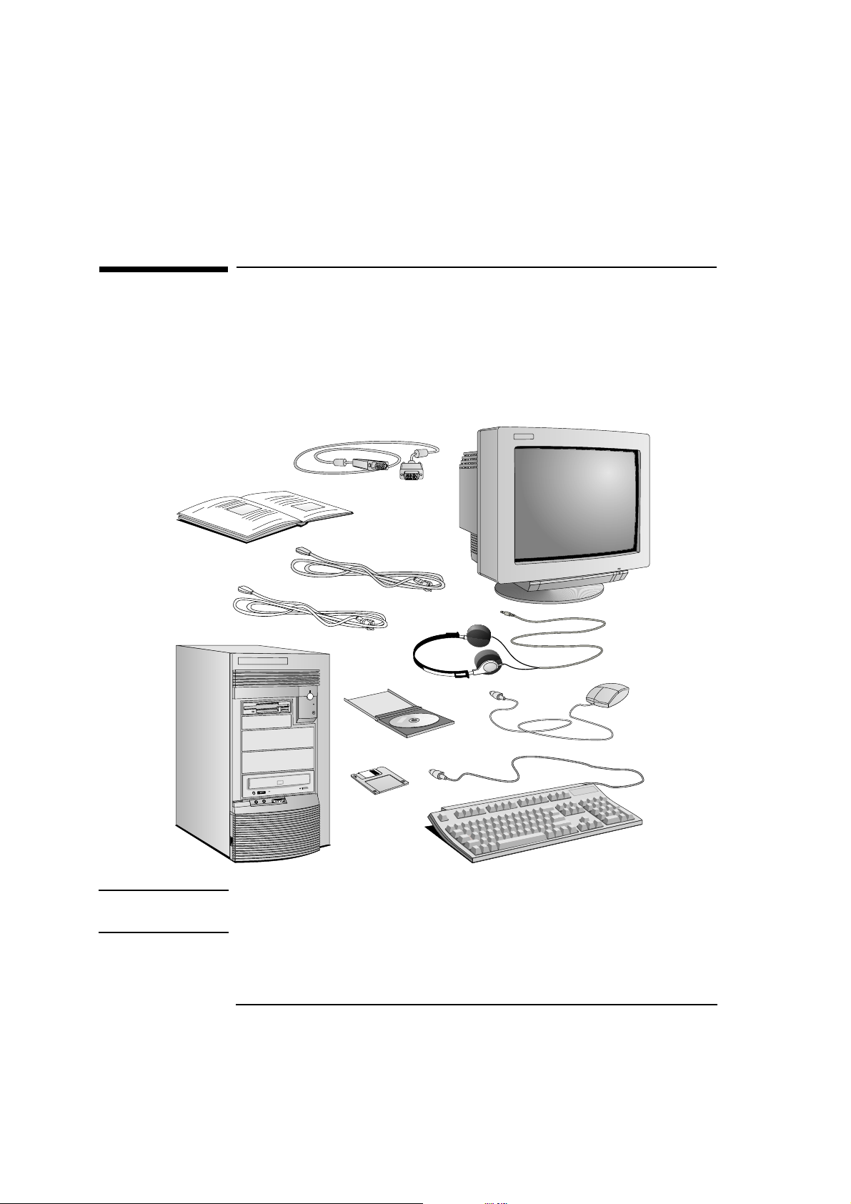
Unpacking Your PC
1 When you receive your PC, unpack all of the components:
• the computer and power cords
• the display and its video cable
• the keyboard, mouse, and headphones
• the manuals and driver kit.
This Manual
Computer
Power Cords
Driver Kit
Video Cable
Display
Headphones
Mouse
Keyboard
NOTE Device drivers, HP utilities, and an online Network Administrator Guide
are provided in a driver kit.
2
Page 15
1 Setting Up Your PC
Unpacking Your PC
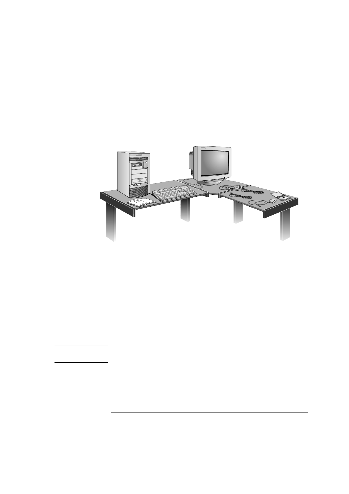
2 Place the PC on (or under) a sturdy desk with easily accessible
power outlets, and enough space for the keyboard, mouse, and any
other accessories.
3 Position the PC so that its rear connectors are easily accessible.
4 Place the display next to the computer.
Installation Tools No tools are required to install your PC. However, if you plan to install a
disk drive or an accessory board inside your PC, you will need a flatblade screwdriver. See chapter 3, How to Install Accessories Inside
Your PC, for more information on installing accessories.
WARNING If you are in any doubt that you can lift the PC and the display safely,
do not try to move them without help.
3
Page 16
1 Setting Up Your PC
Connecting the Display, Mouse, and Keyboard
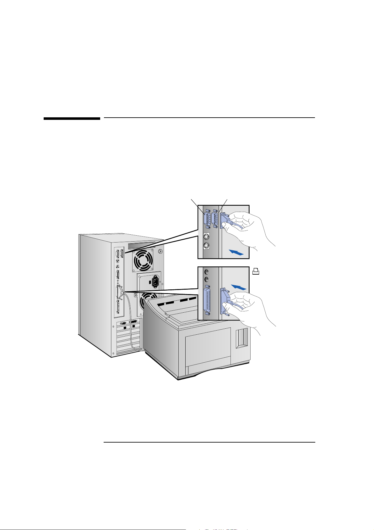
Connecting the Display, Mouse, and Keyboard
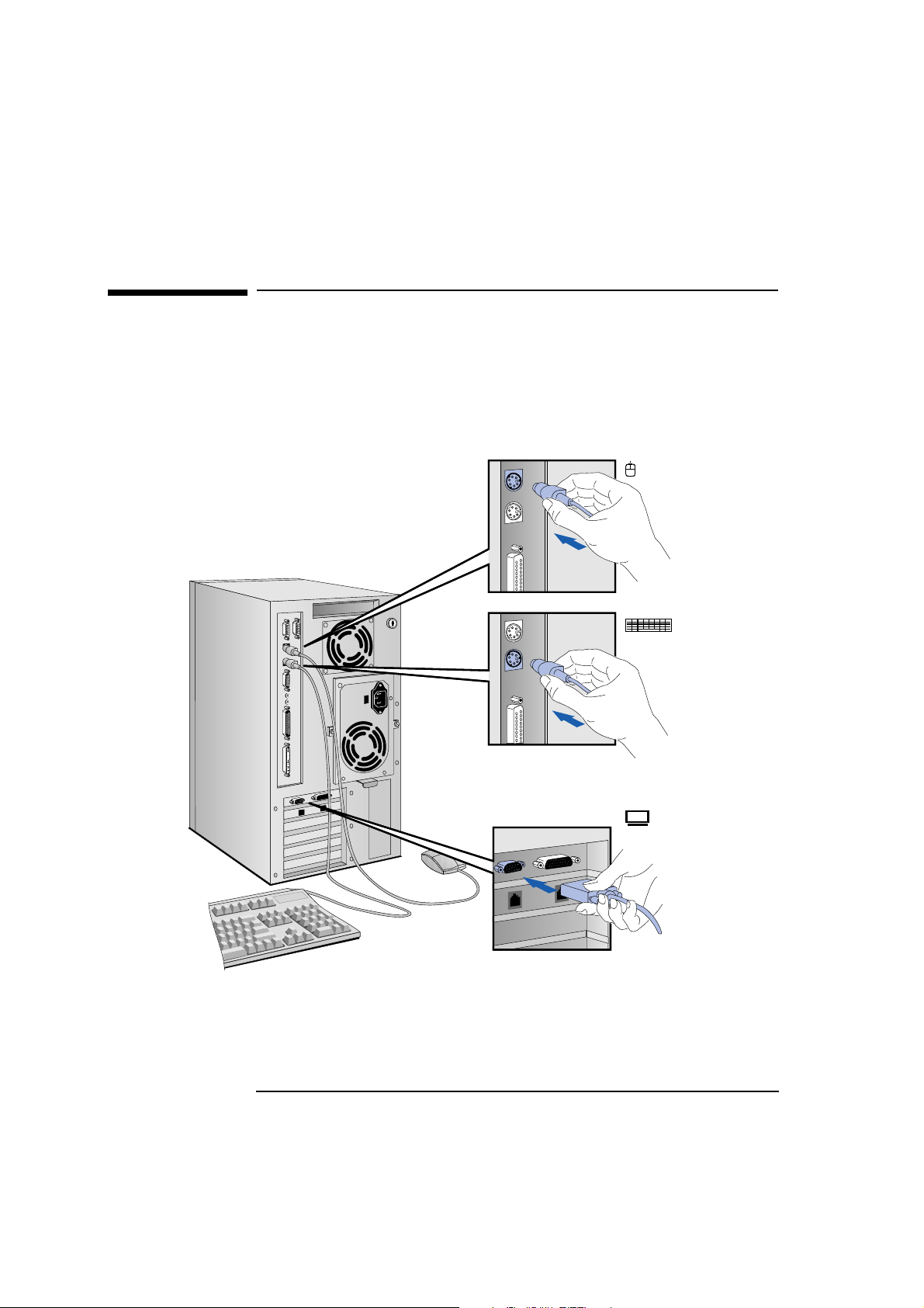
1 Connect the display, mouse, and keyboard to the back of the
computer. The connectors are shaped to go in one way only.
2 Tighten the display cable attachment screws.
Mouse
Connector
Keyboard
Connector
Display
Connector
4
Page 17
1 Setting Up Your PC
Connecting to a Network
Connecting to a Network
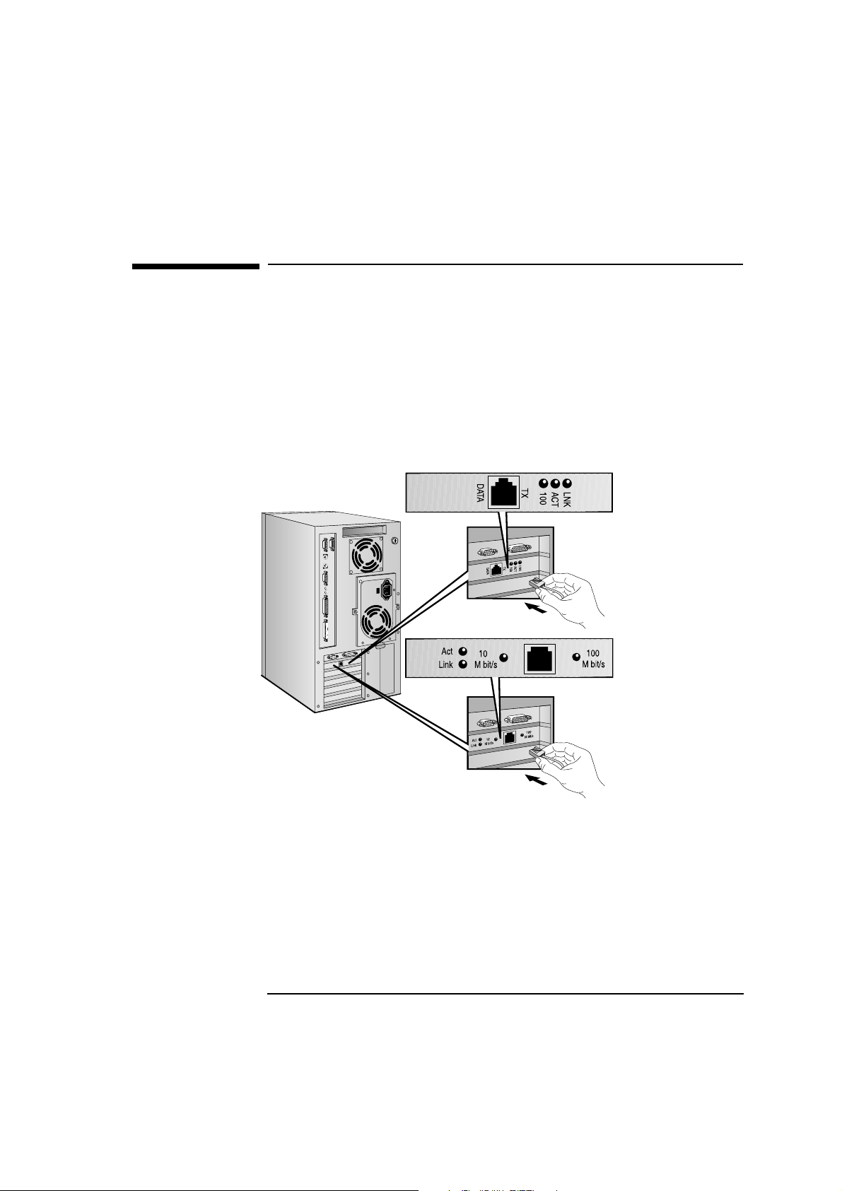
You PC has either a 100Base-T LAN interface adapter or a 100VG LAN
interface adapter. Both LAN adapters support 10Base-T.
The LAN Adapters support both 10 Mbit/s and 100 Mbit/s operation.
They automatically detect which network type is being used.
1 Connect the RJ-45 plug on your network cable to the LAN connector
on the LAN Adapter. Push the plug into the connector until the plug
clicks into place.
Base-T Interface
VG Interface (B model)
2 Attach the other end of the LAN cable to a hub (or into a wall jack
that is connected to a hub).
Let your Network Administrator know you are connecting your PC
to the network. Refer to the online Network Administrator Guide
(provided with the driver kit) for instructions on setting up your PC
for a LAN connection.
5
Page 18
1 Setting Up Your PC
Connecting a Printer
Connecting a Printer
If you have a printer, connect its cable to the back of the computer and
tighten the attachment screws. Use these connectors:
• Parallel (25-pin parallel connector) for a parallel device
• Serial A (9-pin serial connector) for a serial device
• Serial B (9-pin serial connector) for a second serial device.
Serial B
Serial A
Parallel
6
Page 19
1 Setting Up Your PC
Connecting Audio Accessories
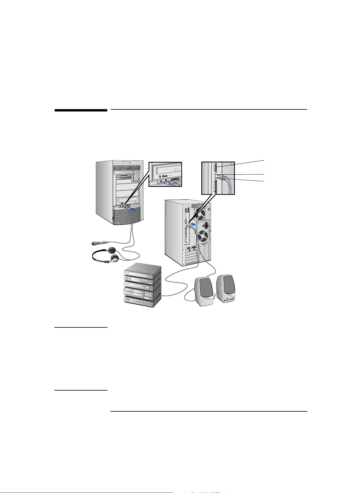
Connecting Audio Accessories
Your PC has a Headphones jack and a Microphone jack on the front
panel. An audio Stereo In jack, an audio Stereo Out jack, and a MIDI
interface connector are located on the rear panel.
MIDI connector
Stereo In jack
Stereo Out jack
NOTE
The internal speaker and the
Stereo Out jack on the rear of
your PC are deactivated when
you use the Headphones jack.
The internal speaker is
deactivated when you use the
Stereo Out jack.
Note that external speakers
should have built-in amplifiers.
The audio accessories shown
here (headphones, microphone,
speakers, and hifi system) are
not supplied with your PC.
WARNING To avoid discomfort from unexpected noise, always turn the volume
down before connecting headphones or speakers.
Listening to loud sounds for prolonged periods may permanently
damage your hearing.
Before putting on headphones, place them around your neck and turn
the volume down. When you put on the headphones, slowly increase
the volume until you find a comfortable listening level, and leave the
volume control in that position.
7
Page 20
1 Setting Up Your PC
Connecting a SCSI Accessory
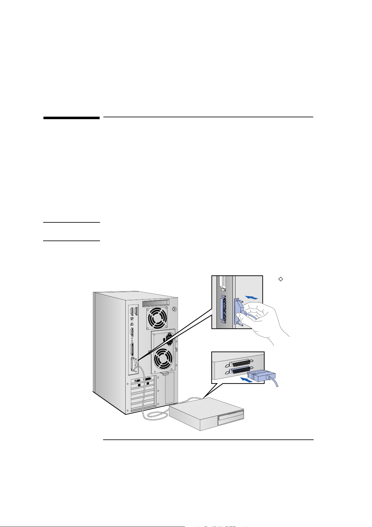
Connecting a SCSI Accessory
Note that Ultra SCSI mode is disabled automatically when an external
SCSI accessory is connected to your PC. To learn how to enable Ultra
SCSI even when an external SCSI device is connected, see “Configuring
the SCSI Interface” on page 96.
1 Refer to the manual provided with the SCSI accessory for
instructions on selecting a SCSI address. You should assign an
unused SCSI address to the accessory. SCSI addresses range from 0
to 7, with SCSI address 0 used by the first SCSI hard disk drive and
SCSI address 7 reserved for the integrated SCSI controller.
NOTE You don’t need to set a SCSI address for Plug and Play SCSI devices
(SCSI devices which support the SCAM protocol).
2 Connect the SCSI accessory to your PC’s external SCSI connector
with a shielded SCSI cable. (Note that Ultra SCSI is automatically
disabled when an external SCSI accessory is connected.)
SCSI
8
Page 21
1 Setting Up Your PC
Connecting a SCSI Accessory
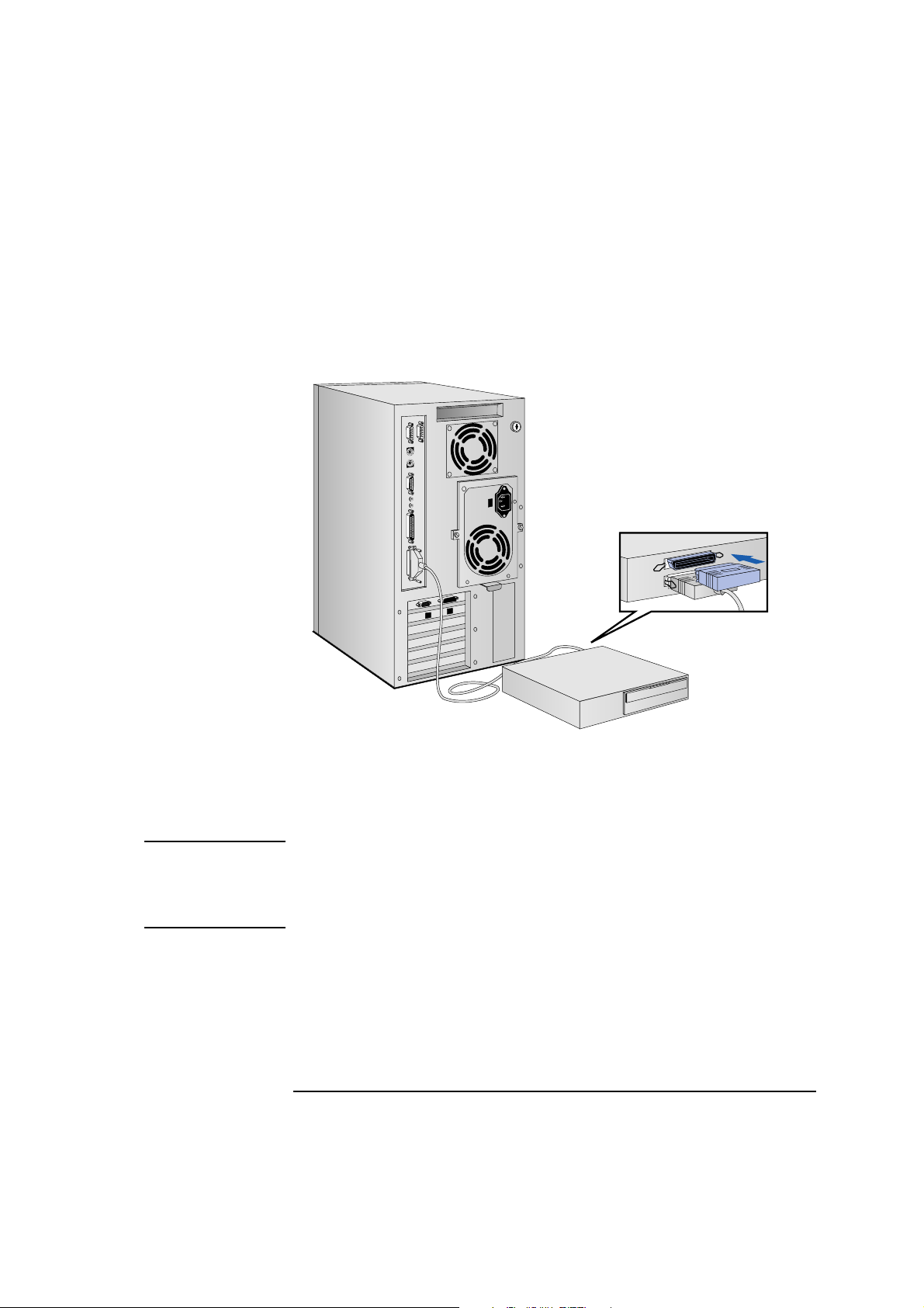
3 Make sure the SCSI accessory is terminated correctly—either
internally or by a terminating resistor (refer to the manual provided
with the SCSI accessory).
Make sure the SCSI accessory
is terminated
4 Refer to the manual provided with the SCSI accessory to learn how
to install any software that may be necessary to use it.
NOTE The total length of the external SCSI cables should not exceed 3 meters
(approximately 10 feet).
Contact your dealer to order shielded HP SCSI cables to connect
external SCSI accessories.
9
Page 22
1 Setting Up Your PC
Connecting the Power Cords
Connecting the Power Cords
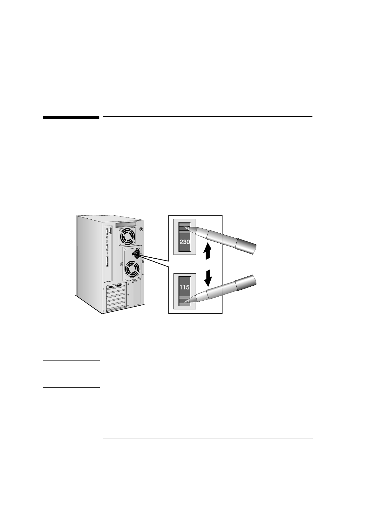
1 If fitted, remove the warning label covering the computer’s power
connector on the rear of the computer.
2 Check that the voltage selection switch has been correctly
configured for your country.
Voltage
Selection Switch
If the voltage
selection is
incorrect for your
country, select the
correct voltage
115 V or 230 V
NOTE You should not have to change the voltage selection switch setting if the
computer was ordered from HP with the correct localization option for
your country.
10
Page 23
1 Setting Up Your PC
Connecting the Power Cords
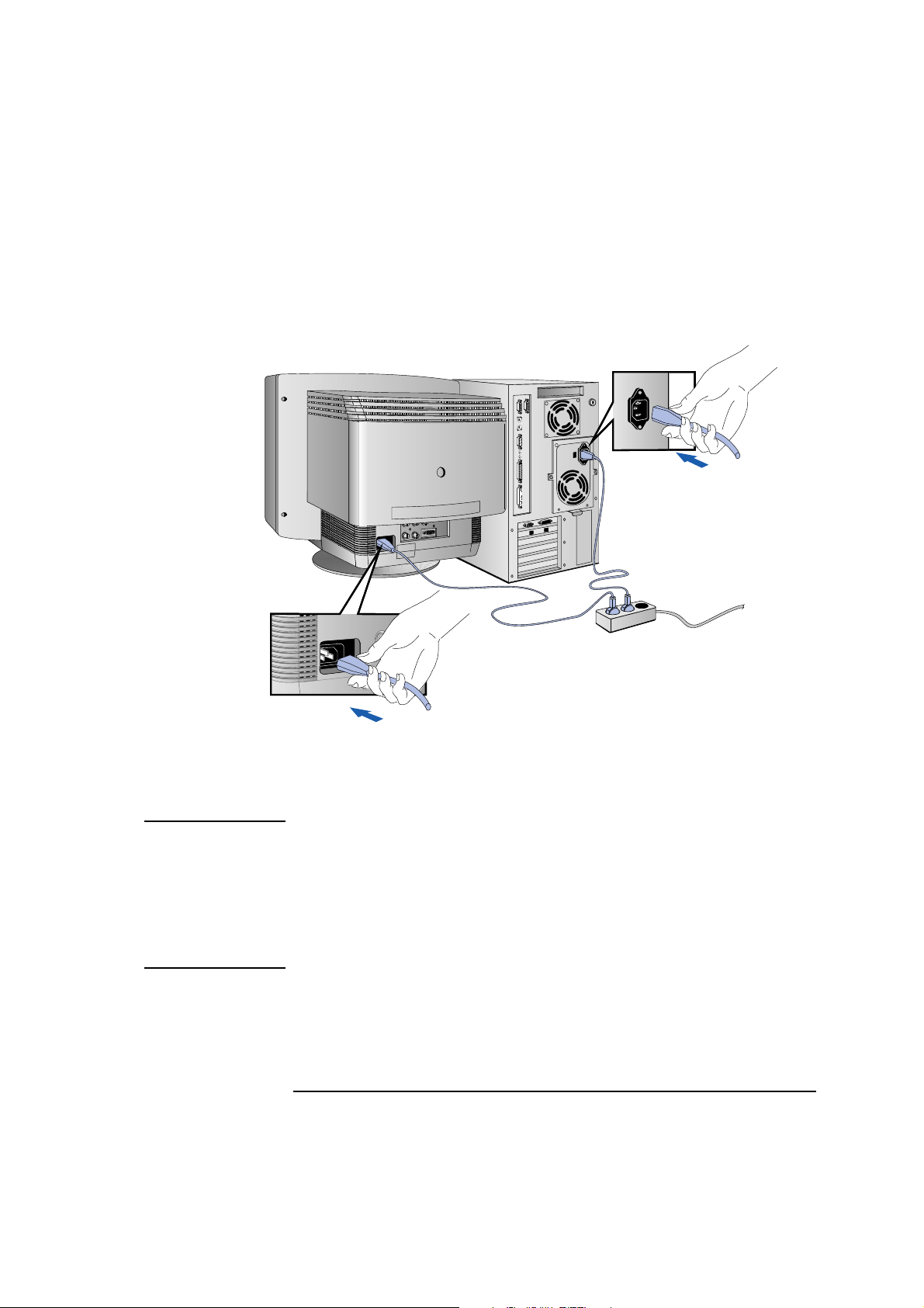
3 Connect the power cords to the display and the computer. (The
connectors are shaped to go in one way only.)
Computer
Power Connector
Display
Power Connector
Grounded Outlet
4 Connect the display’s power cord and the computer’s power cord to
grounded outlets.
WARNING For your safety, always connect the equipment to a grounded wall
outlet. Always use a power cord with a properly grounded plug, such
as the one provided with this equipment, or one in compliance with
your national regulations.
This PC is disconnected from the power by removing the power cord
from the power outlet. This means the PC must be located close to a
power outlet that is easily accessible.
11
Page 24
1 Setting Up Your PC
Starting and Stopping Your PC
Starting and Stopping Your PC
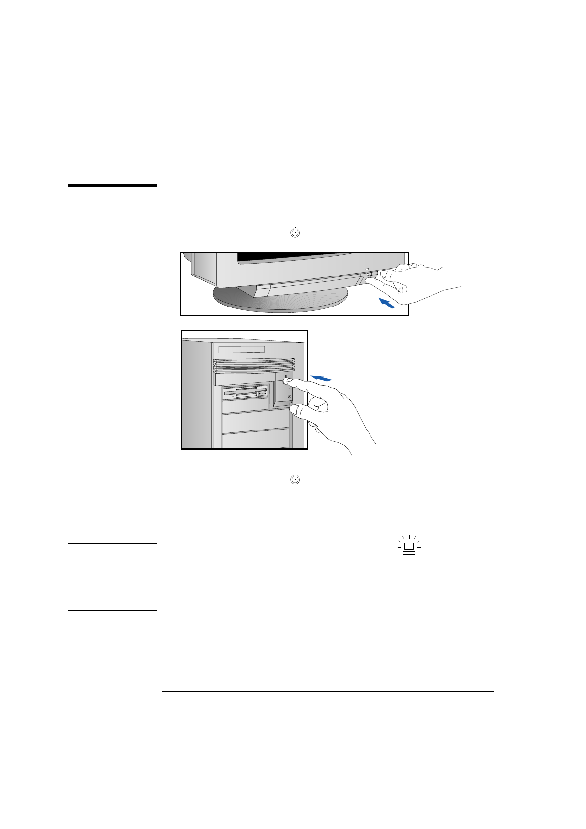
Starting Your PC 1 Press the power button on the display.
Then switch
on the PC
Switch on the Display
2 Press the power button on the PC.
The PC performs a power-on self-test. If an error is detected, a
message is displayed. Follow the instructions provided to correct
the error.
NOTE If the space bar on your keyboard has a power-on icon, you can
start the PC by pressing the space bar. (This feature can be enabled or
disabled with the Setup program — see chapter 4 for more information
about the Setup program.)
Note that you cannot stop your PC by pressing the space bar.
12
Page 25
1 Setting Up Your PC
Starting and Stopping Your PC
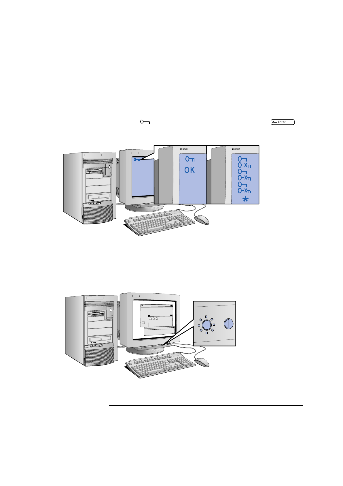
3 If a Password has been set in the PC’s Setup program, the power-on
prompt appears when you switch on the PC. If the power-on
prompt is displayed, type your Password and press to
use the PC.
Correct password
Wrong password
Restart the PC, then
enter your password
again.
4 When your PC has started:
• Adjust the display screen’s brightness and contrast to your needs.
If the picture does not fill the screen or is not centered refer to
the display’s manual for instructions.
• Set the keyboard to a comfortable position.
Adjust brightness
(your display may be different
from the display shown here)
13
Page 26
1 Setting Up Your PC
Starting and Stopping Your PC
Stopping Your PC 1 To stop your PC, make sure that you have exited all programs then
shutdown your operating system (refer to your operating system
reference guide for details if you are not sure how to shutdown your
operating system).
2 Press the power button to stop your PC.
Resetting Your PC The Reset button lets you restart the PC without switching the PC off
and then on again. Make sure that you have exited all programs then
shutdown your operating system before you press the reset button.
You may need to
push hard on the
Reset button
14
Page 27

2
Using Your PC
This chapter gives important ergonomic advice, explains how to set a
password, and shows how to use your CD-ROM drive.
Page 28

2 Using Your PC
Working in Comfort
Working in Comfort
Thank you for choosing Hewlett-Packard equipment. To maximize your
comfort and productivity it is important that you set up and use your
equipment properly. This section of the User’s Guide provides
guidance and hints, based on the latest ergonomic findings, to help you
work in a comfortable and ergonomically low-risk environment. Also,
international regulations and guidelines are included from the
European Community Display Screen Equipment directive and ISO
9241 to ensure that the information presented is applicable worldwide.
Please be aware that the quoted dimensions are for an average person.
They may need to be adjusted to your individual physical
characteristics. For example: if you are an extra tall person, your work
surface may need to be higher than the range listed. Prior to using any
Hewlett-Packard equipment, study these instructions and suggestions
and consult the bibliography at the end of this section. If, during use of
this or any other equipment, you experience pain or discomfort, stop
work and review this section of the User’s Guide. Should the
discomfort return, discontinue use of the equipment and consult a
doctor as soon as possible.
Repetitive Strain Injury
Because your safety and comfort is our primary concern, we strongly
recommend that our equipment be used in accordance with ergonomic
standards and recommendations. Recent literature suggests that there
may be a relationship between injury to soft tissues, especially in the
hands and arms, and the prolonged use of keyboards or other
equipment requiring repeated motions of the hands and forearms.
Literature also suggests that there are many other risk factors which
may increase the chance of such soft-tissue injury, commonly called
Repetitive Strain Injury.
16 English
Page 29

2 Using Your PC
Working in Comfort
Questions and Answers
What is RSI? Repetitive Strain Injury (RSI - also known as cumulative trauma
disorder or repetitive motion injury) is a type of injury where soft tissue
in the body, such as muscles, nerves, or tendons, become irritated or
inflamed. In an extreme case, this irritation can lead to permanent
tissue damage. RSI has been a reported problem for workers performing
specific tasks such as assembly line work, meat packing, sewing, playing
musical instruments, and VDT work. It may also result from other
activities such as carpentry, knitting, housework, gardening, tennis,
wind surfing, and lifting children.
Why is it important for
me to exercise care in
how I set up and use
my equipment?
Some people who use VDTs experience physical discomfort during their
use. Sometimes this discomfort leads to a repetitive strain injury.
Setting up and using equipment properly can help to minimize this
discomfort. Use your equipment in an appropriate way. Well-designed
and adjusted equipment may not be sufficient to eliminate all potential
problems. How you perform your VDT activities is also important.
What causes RSI? RSI is caused by any demanding activity that exceeds the ability of the
body to do work. Common factors that are associated with RSI include
too many uninterrupted repetitions of an activity or motion, performing
an activity in an awkward or unnatural posture, maintaining static
posture for prolonged periods, failing to take frequent short breaks, and
stress. Also, certain medical conditions such as rheumatoid arthritis and
diabetes may contribute to RSI.
What should I do if I
start to experience RSI
symptoms or
discomfort?
By following the guidance on proper equipment and work environment
set up and use, the risk of developing RSI can be minimized. However,
if you are experiencing any discomfort, seek professional medical advice
immediately. Typically, the earlier a problem is diagnosed and treated,
the easier it may be to resolve.
English 17
Page 30

2 Using Your PC
Working in Comfort
Installing Your Display
Most HP displays come with a tilt and swivel feature that makes it easy
to adjust the screen position. If your display does not have this feature,
consider acquiring an accessory to provide this capability. The
optimum distance between the eyes and the screen depends on the
size of the displayed characters.
• Optimum readability is generally considered to be 21 minutes of arc.
This corresponds to a character size of 3.7 mm (0.15 in) at a viewing
distance of 60 cm (24 in).
• If your eyes are closer to the screen than 50 cm (20 in) undue stress
may occur: Most people prefer a viewing distance of approximately
60 cm (24 in).
• The maximum viewing distance is usually limited by the character
size and the available space on the desk top.
The top of your display screen should be at or slightly below eye level.
This will keep you from looking down more than 15 to 20 degrees to
see the center of the screen. You should not have to look down more
than 60 degrees for normal work tasks, such as typing or reading.
Ideally the screen should be positioned perpendicular to your line of
sight. In case of undesirable reflections, tilting the screen forward
slightly usually solves the problem. However, if this is not sufficient, it
may be necessary to change the position of the display on the desk, or
change the location of the desk.
If this still does not correct the problem, try a good quality anti-glare
filter, or a screen hood.
Keep the contrast and brightness adjusted to the level that is most
comfortable for you. High contrast and low brightness is usually the
preferable combination. Since build up of screen dirt is gradual and
therefore often overlooked, don't forget to clean the screen on a
regular basis.
18 English
Page 31

2 Using Your PC
Working in Comfort
What is Displayed on the Screen
Text should be easy to read. To help ease eye strain, try to adjust text
attributes to make reading the display as easy as possible (adjust such
attributes as character size, spacing, and color).
NOTE The ISO 9241 and ANSI/HFS 100-1988 standards give ample technical
recommendations on how to achieve good readability.
If the image on your screen is not stable, the display may require repair
or adjustment.
When possible, use a program that has a simple "machine/user
interface". Also, screen information should be displayed in a structured
and well organized way.
Using a Document Holder
A document holder may make it easier to transfer information from a
document to the screen (or if you need to read while using your
system).
If using a document holder, it should be at the same distance from your
eyes as the screen, next to the screen, and at the same height as the
screen. An alternative location preferred by some people is to locate
the document holder between the screen and keyboard.
To help reduce stress on your neck and prevent eye fatigue, keep the
back and forth movement of your head and eyes to a minimum while
using a document holder.
English 19
Page 32

2 Using Your PC
Working in Comfort
Your HP Keyboard
Your HP keyboard has a long cable so you can place it in the position
most comfortable for you while you are using the system.
The keyboard has a low profile to prevent excessive bending of your
wrists while typing. Literature suggests that you should not bend your
wrists more than 10 degrees up or down, or more than 10 degrees
sideways. Keep your wrists straight by moving your entire hand and
forearm over to use the function keys or numeric keypad.
Your HP keyboard may have a kickstand which can be opened or
closed to raise or lower the keyboard angle. If your elbows are at about
the same level as the work surface, then you may choose not to use the
kickstand. If your elbows are below the work surface, you may wish to
raise the back of the keyboard by using the kickstand. The point is to
make sure that your hands are in a "neutral" or flat position when you
use the keyboard. This means that your forearms, wrists, and hands
should be in straight line.
You may use a wrist rest to help keep your wrists in a more comfortable
and neutral position. If you use a wrist rest, ensure that it is flush in
height with the front edge of the keyboard, and rounded or padded.
Try not to rest your wrists on a sharp edge, such as a desk edge, when
typing.
20 English
Page 33

2 Using Your PC
Working in Comfort
It is recommended that you place your keyboard in front of the screen
or document holder (whichever is viewed the most).
If you use a mouse or trackball, position it close to the keyboard so you
do not have to stretch while using it.
It is not necessary to type with very much force. Use of too much force
can place unnecessary stress on your body, including tendons and
muscles in your hands, wrists, and forearms, and increase risk of
discomfort or injury.
Your Desk
Sufficient desk space should be available to allow you to set up your
equipment in a convenient, comfortable arrangement. Recommended
workstation desk space is 160 by 80 by 90 cm (63 by 32 to 36 inches).
Depending on the nature of your work, you may need a smaller or
larger work surface.
To minimize reflections and glare (and thus eye discomfort), the
surface of the desk should be non-reflective (matt).
Ideally, the work top height should be adjustable. Recommended range
is 66 to 77 cm (26 to 30 inches). If the desk top height is fixed, it should
be between 72 and 75 cm (28.5 to 29.5 inches).
There should be at least 6 cm (2 inches) of space between your thighs
and the desk top. If the desk has a "kneehole" it should be at least 58
cm (23 in) wide, 65 cm (25.5 in) high, and 60 cm (24 in) deep.
If possible, choose a desk with cable management capabilities. This will
keep your cables and wires orderly, off the floor, and out of the way.
Your Chair
Your chair should have a stable base (for example: five legs with
casters). It is important that the casters be matched to the type of floor
in your workspace (that is, hard surface or carpet).
English 21
Page 34

2 Using Your PC
Working in Comfort
The chair must provide a comfortable sitting position.
• You should be able to easily adjust the height. Minimum range should
be 40 to 52 cm (15.5 to 20.5 in) as measured from the floor.
• It should have a back support that is adjustable in both height and tilt
(0 to 30 degrees backwards). It is important that your lower back be
correctly supported (lumbar curve of the back).
• You should be able to freely swivel from side to side.
• The front of the seat should be curved (“waterfall” edge), and the
chair fabric should be breathable.
If your chair has armrests, they should be fully adjustable. The arms
should not interfere with adjusting the chair or moving it close to the
desk.
Adjust the chair so that the work surface is at elbow height.
If the chair has an adjustable seat pan, inclining the seat slightly
forward will transfer some of the pressure from the spine to the thighs
and feet. This will relieve spine fatigue.
Use a chair with an adjustable
lumbar (back) support, which
can be moved up and down.
Adjust the back of the chair so
that the part that curves
outward (towards the front of
the chair) corresponds to the
part of your lower back that
curves inward. (Portable lumbar
cushions are also available at
medical and office supply
houses.)
22 English
Adjust the angle of the back
rest and seat tilt so that your
back is erect or angled slightly
backward (90 to 110 degrees).
Some people feel more
comfortable up to a 135 degree
angle.
Page 35

2 Using Your PC
Working in Comfort
Your Posture
While sitting at your workstation, your back should be erect or angled
slightly backwards. Your back should be supported by the backrest.
Your arms should be relaxed and loose, elbows close to your sides, with
the forearms and hands approximately parallel with the floor.
Your wrists should be as straight as possible while using the keyboard,
mouse, or trackball. They should not have to be bent upward,
downward, or to either side more than 10 degrees.
Your thighs should be horizontal or bent slightly downward. Your lower
legs should be near a right angle to your thighs. Your feet should rest
comfortably on the floor (flat). If necessary, use a footrest to get into a
comfortable position.
Your head should be upright or tilted slightly forward (but not more
than 15 degrees).
Avoid working with your head or trunk twisted in an unnatural
position.
Change your position frequently to avoid fatigue.
Your Workspace and Work Environment
To prevent muscle stiffness, you must have enough space to move
around and vary your position. Do not remain in one position for
extended periods of time.
For better eye relief, the ceiling, walls, and floors should have a
medium level of reflectance (approximately 75%, 40%, and 30%
respectively). Try to avoid excessive contrast between the screen and
its surroundings.
The work environment should be as quiet and free of distraction as
possible (background noise preferably below 55 dBA).
Where possible, relative air humidity should be in the range of 40 to
60%.
English 23
Page 36

2 Using Your PC
Working in Comfort
The recommendation for room temperature is 19 to 23 degrees C (66
to 73 degrees F). If possible, adjust the temperature for whatever is
comfortable to you.
The workplace should be well ventilated (as with any indoor
environment).
Lighting
Lighting in your area should allow easy reading of documents and
keyboard legends.
Recommended levels are:
• Not too bright. Values over 1000 lux (100 foot candles) are
considered to be too bright.
• Recommended value is between 300 and 500 lux (30 to 50 foot
candles).
• For work on the screen, 300 lux (30 foot candles) is enough for most
work.
• When documents are to be read, 500 lux (50 foot candles) is
recommended.
If more light is needed for a particular task, use an individual lamp
("task lighting") rather than increasing the general lighting.
Incoming light should be shielded or diffused to prevent glare and
distracting reflection. In cases where strong sunlight is a problem,
curtains, adjustable shades, or display hoods are recommended.
If possible, try not to position the display in front of windows where
glare, high contrast, and reflections will interfere with your screen
presentations. Try to position the display so the screen is at a right
angle to the window.
24 English
Page 37

2 Using Your PC
Working in Comfort
Further Suggestions
• Have your eyes checked on a regular basis and ensure your eyeglass
prescription is suitable for working on a display screen.
• Look away from the screen from time to time to help reduce eye
strain. Focus on distant objects briefly. Also, blinking periodically
helps lubricate the eyes.
• Avoid holding your muscles tensed for long periods of time. Keep
your fingers and body relaxed.
• Changing tasks frequently will help prevent muscle stiffness. For
example: alternating between using the keyboard, writing, filing, and
moving around in your work environment, helps keep muscles loose.
• When prolonged screen work is required, take frequent short breaks.
As a rule of thumb, a five or ten minute break every hour is a good
idea. Short frequent breaks are more beneficial than longer less
frequent breaks. Data shows that people who work for long lengths
of time without a break are more prone to injury.
• Occasionally stretch the muscles in your hands, arms, shoulders,
neck and back. You should stretch at least as often as you take your
breaks, that is, at least once per hour.
• Discomfort, if any, may be alleviated by use of alternative ergonomic
designs and accessories such as: ergonomic personalized chairs,
wrist rests, keyboard trays, alternative input devices, nonprescription eye glasses, glare screens, and more. Seek additional
information from the sources available to you, including your
employer, doctor, local office supply store, and the bibliography
provided at the end of this section.
• If you experience any discomfort, discontinue use and see a doctor
as soon as possible. If you want additional information on VDT setup,
ergonomics and related topics, consult your employer and the
sources listed at the end of this section.
English 25
Page 38

2 Using Your PC
Working in Comfort
Summary Recommendations
The recommendations in the following illustrations are drawn from the
latest available international ergonomic standards and
recommendations, including ISO 9241 and ANSI/HFS 100-1988.
Do not tilt your head forward by more
than 15 degrees, and try not to turn your
head toward the side.
Make sure frequently used
equipment is within easy reaching
distance from your body. For
example, if you are primarily using
the keyboard, place it directly in
front of you, not to the side. If you
are primarily using the mouse,
place it in front of your hand or
arm.
If you are using both a mouse and
a keyboard, place them both at
the same work surface height.
Adjust your seat height, work surface or
both to position the surface at
approximately elbow height.
Place your display so that the
top of the screen is at or
slightly below eye level (but no
more than 15 degrees).
If a wrist rest is used, the height
should be flush with the front
edge of the keyboard.
Make sure there is
sufficient room under
the work surface for
your legs.
If after adjusting your chair, you cannot rest your
feet comfortably on the ground, use a footrest,
preferably adjustable in height and angle.
Remember to occasionally shift position and move
your body. Keeping your body “locked” in one
position for a long period of time is unnatural and
stressful.
26 English
Page 39

2 Using Your PC
Working in Comfort
Make sure your arms and elbows
are relaxed and loose, with your
upper arm perpendicular to the
floor or slightly forward (no more
than 30 degrees).
Keep your elbows close to your sides
(less than 20 degrees away from your
body).
Keep your forearms and hands
approximately parallel with the floor.
(Elbows bent between 70 and 115
degrees).
English 27
Page 40

2 Using Your PC
Working in Comfort
Bibliography of Articles for More Information
1 Caisse Nationale d’Assurances: “Le travail a l’écran de visualisation”,
Lucerne (Switzerland), 1991.
2 Bayerisches Staatsministerium für Arbeit: “Arbeiten mit dem
Bildschirm - aber richtig!”, Max Schick GmbH, Munich, 1992.
3 U.S. Department of Labor/Occupational Safety and Health
Administration: “Ergonomics: the study of work”, U.S. Government
Printing Office, Washington D.C., 1991.
4 International Standards Organization: “ISO 9241: Ergonomic
requirements for office work with visual display terminals (VDTs)”,
Geneva, 1992.
5 Eric Granjean: “Ergonomics in Computerized Offices”, Taylor &
Francis, London, 1987.
6 European Community: “Council directive of 29 May 1990 on the
minimum safety and health requirements for the work with display
screen equipment”, Directive 90/270/EEC, Brussels, 1990.
7 U.S. Department of Labor/Occupational Safety and Health
Administration: “Working safely with video display terminals”, U.S.
Government Printing Office, Washington D.C., 1991.
8 Swedish National Board of Occupational Safety and Health: “Work
with Visual Display Units (VDUs)”, Ordinance AFS 1992:14,
Stockholm, 1992.
28 English
Page 41

Configuring Password Security
Configuring Password Security
You can set two passwords, which can be used to provide two levels of
protection for your PC.
User Password The User Password provides these security features:
• a power-on password prompt to prevent your PC being started in
your absence
• a keyboard lock timer which you can use to lock your PC after a
specified number of minutes of keyboard inactivity
• screen blanking to conceal confidential data when the PC is locked.
2 Using Your PC
System Administrator
Password
Set the System Administrator Password to protect the PC’s
configuration in Setup. The PC can be started, but the System
Administrator Password must be entered before any Setup options
(except User Preferences) can be modified.
English 29
Page 42

2 Using Your PC
Configuring Password Security
Setting a Password
1 Turn on the PC and the display.
If the PC is already turned on, exit all applications and then press
and to restart the PC.
Delete
2 When
<Setup=F2> appears on the screen press .
3 The PC’s Setup program will appear.
HP Vectra PC Setup xxx.xx.xxx.xx F1=Help On/Off
Date (Year/Month/Day) . . . . . . . . 1996 / 01 / 01
Time (Hour/Minute/Second) . . . . . . 09 : 10 : 35
HP VECTRA XU 6/xxx
<Setup=F2>
CONFIGURATION SUMMARY
System BIOS Version . . . . . . . . xx.xx.xx
MILLENNIUM Video Board . . . . . . VRAM: 2.0 MB, Version: xxx-x
Processor . . . . . . . . . . . . . Pentium(TM) Pro, xxx MHz
30 English
Page 43

Configuring Password Security
4 Use the or key to move the highlight to the
User Password line.
HP Vectra PC Setup xxx.xx.xxx.xx F1=Help On/Off
USER PREFERENCES
Operating System . . . . . . . . . Windows NT
User Password . . . . . . . . . . . Not Set
5 To set your User Password, press once.
a Type your password and press .
b Type your password and press again.
2 Using Your PC
The screen displays
User Password . . . . . . . Set
6 If you wish to erase your Password, press twice.
If you only want to set a password, press the key now to save
your password and exit SETUP.
English 31
Page 44

Your CD-ROM drive
may be different from
the drive shown here
— the Headphones
Socket and Volume
Control may not be
present.
2 Using Your PC
Using Your CD-ROM Drive
Using Your CD-ROM Drive
Your CD-ROM drive reads information or programs on a Compact Disc
(CD). It cannot record to a CD. To learn how to access information
stored on a CD, refer to the documentation supplied with the CD.
6
5 4
3
2 1
1. Open/Close Button Opens or closes the CD-ROM drawer.
2. Emergency Eject Used to open the CD-ROM drive mechanically
when the power supply is off.
3. Door Protects the CD-ROM drive from dust
contamination and accidental damage.
4. Busy Indicator Glows when the drive is ready and when the
drive is busy.
5. Volume Control Adjusts the volume of music played through
headphones connected to the CD-ROM drive.
6. Headphones Socket Lets you listen to music CDs by connecting
headphones directly to the CD-ROM drive
using a stereo mini-jack. (This does not cut
out the speakers.) Adjust the volume using
the Volume Control, and not using the audio
software.
32 English
Page 45

2 Using Your PC
Using Your CD-ROM Drive
WARNING To avoid electrical shock and harm to your eyes by laser light, do not
open the CD-ROM drive enclosure. The CD-ROM drive should be
serviced by service personnel only. Do not attempt to make any
adjustment of the unit.
Loading a CD
1 Press the Open/Close button to open the CD drawer.
2 Place the CD, label side facing up, in the recess in the drawer.
3 Press the Open/Close button to close the drawer. The drawer can
also be closed by gently pushing the drawer back into the drive.
4 To remove the CD, press the Open/Close button to open the drawer.
Remove the CD. Press the Open/Close button to close the drawer.
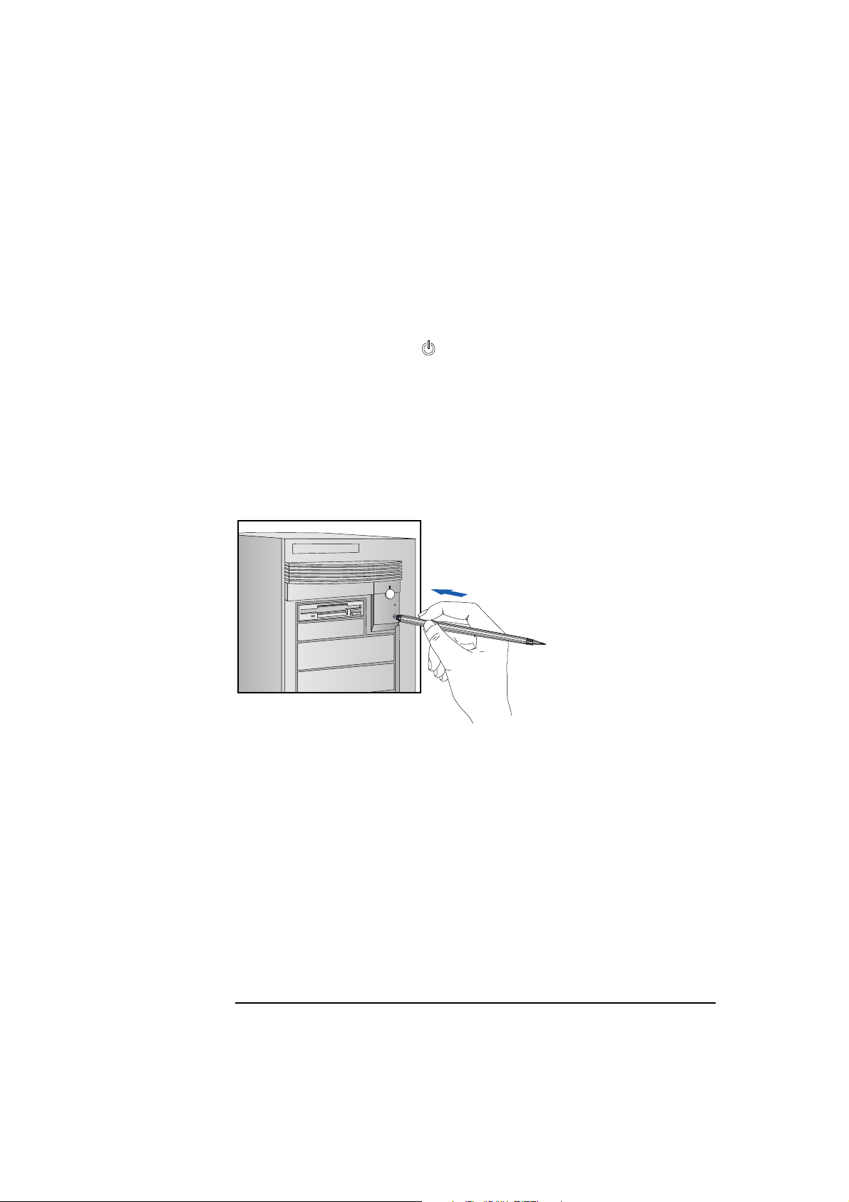
Ejecting a CD When the Open/Close Button is Disabled
If the Open/Close button is disabled by software or a power failure, use
this procedure to remove a CD:
1 Turn off the PC.
2 Insert a straight rod (for example, a straightened paper clip) into the
emergency eject hole next to the Open/Close button. The drawer
should eject by about 15mm.
3 Pull out the drawer by hand until the CD can be easily removed.
4 Remove the CD.
5 Push the drawer gently back into the drive.
English 33
Page 46

2 Using Your PC
Tips for Using Your PC
Tips for Using Your PC
If you want to: You need to:
1 Install hardware accessories. Refer to chapter 3 “How to Install Accessories
Inside Your PC”.
2 Configure hardware accessories. Refer to chapter 3 “How to Install Accessories
Inside Your PC”.
3 Install new applications, and set up and use
an application.
4 Make more disk space available. Delete unnecessary files and increase disk space
5 Make more memory available. Install more main memory. Refer to chapter 3.
6 Display more colors. Install more video memory. Refer to chapter 3.
7 Stop anyone from starting the PC in your
absence.
Read the manuals supplied with the application
software.
by using a disk compression program.
Install a larger disk drive.
Run the built-in Setup program and set a
Password. Refer to this chapter for details.
34 English
Page 47

3
How to Install Accessories
Inside Your PC
This chapter explains how to install accessories, such as extra memory,
accessory boards, and additional disk drives, in your PC.
Page 48

Internal Mass Storage
Devices
3 How to Install Accessories Inside Your PC
Supported HP Accessories
Supported HP Accessories
This chapter describes how to install memory, mass storage devices,
and accessory boards in your computer.
Main Memory Upgrades (ECC, 60 ns):
32 MB (2 × 16 MB), order D3555A
64 MB (2 × 32 MB), order D3554B
128 MB (2 × 64 MB), order D3540A
Mounting Trays:
3.5-inch disk drive trays, 5-pack,
order D2037A
Rails for Front Access Devices:
5.25-inch disk drive rails,
order D2880A
3.5-inch disk drive rails,
order D3566A
36 English
Front Access Drives, for example:
3.5-inch 1.44 MB flexible disk drive
(one third height), order D2035B
5.25-inch 1.2 MB flexible disk drive
(half height), order D2881B
Page 49

Contact your dealer for an up-to-date list of supported devices.
Up to six accessory boards
can be installed:
three 32-bit PCI slots
two 16-bit ISA slots
one combination ISA or PCI slot
3 How to Install Accessories Inside Your PC
Supported HP Accessories
WARNING For your safety, never remove the computer’s cover without first
removing the power cord and any connection to a telecommunications
network. Always replace the cover before switching on the computer.
English 37
Page 50

3 How to Install Accessories Inside Your PC
Removing and Replacing the Cover
Removing and Replacing the Cover
1 Switch off the display and computer.
2 Disconnect the power cords from the power outlets, computer, and
display. Disconnect any telecommunication cables from the
computer.
Disconnect the power cords
3 If necessary, unlock the cover using the key provided with the
computer (the lock is on the back of the computer).
38 English
Page 51

3 How to Install Accessories Inside Your PC
Removing and Replacing the Cover
4 Lift the two securing latches at the front of the computer.
Lift the securing
latches
5 Slide the cover forward until it is clear of the computer.
If you have difficulty
removing the cover, try
pushing gently against
the CD-ROM drive with
your thumbs as you pull
the cover towards you
English 39
Slide the cover
clear of the
computer
Page 52

3 How to Install Accessories Inside Your PC
Removing and Replacing the Cover
Replacing the Cover after Installing Accessories
1 Check that you have installed all your accessories (and removed a
plastic panel from the front of the cover, if you installed a disk drive
in a front shelf).
2 Check that all internal cables are safely routed.
3 Check that the cover is unlocked and the latches are outwards.
4 Place the cover in front of the computer and ensure that the two lips
at the bottom of the case slide onto the two rails at the base of the
computer.
Slide the cover
into position
Check that the lips at the
bottom of the case slide
onto the rails at the base
of the computer
5 Slide the cover into position.
40 English
Page 53

3 How to Install Accessories Inside Your PC
Removing and Replacing the Cover
6 Push the two latches at the front of the cover downwards until they
click into position.
Lock the cover
(at the back of
the computer)
7 If required, lock the cover using the key.
8 Reconnect all cables and power cables.
Push the latches
down to secure
the cover
English 41
Page 54

3 How to Install Accessories Inside Your PC
Moving the Power Supply
Moving the Power Supply
You can slide the power supply unit out of the computer to improve
access to the system board and the cables at the rear of the disk drives.
1 Disconnect the computer’s power cord and any telecommunications
cable.
2 Remove the computer’s cover (see page 38).
3 Unscrew the two self-retaining screws at the back of the power
supply.
Unscrew the
self-retaining
screws
WARNING To avoid electrical shock, do not open the power supply.
42 English
Page 55

3 How to Install Accessories Inside Your PC
Moving the Power Supply
4 Slide the power supply out of the computer until it stops—the power
supply unit remains connected to the computer.
Slide the power
supply unit clear of
the computer
Replacing the Power Supply after Installing Accessories
1 Check that all internal cables are safely routed.
2 Slide the power supply back into the computer.
Power
Supply
3 Tighten the two self-retaining screws.
English 43
Page 56

3 How to Install Accessories Inside Your PC
Installing Memory
Installing Memory
Main Memory Modules
Your PC is supplied with main memory. If you need more main memory
to run your application software, you can install up to a total of 512 MB.
Main memory upgrades are available in pairs of 16 MB, 32 MB or
64 MB.
Memory modules must be installed in identical pairs of the same size
and same type (a pair of ECC or a pair of non-ECC) from bank A, up to
bank D. For a list of available memory modules, refer to the beginning
of this chapter.
Error correcting will be disabled if any non-ECC memory is installed.
CAUTION Static electricity can damage electronic components. Turn all
equipment OFF. Don’t let your clothes touch the accessory.
To equalize the static electricity, rest the accessory bag on top
of the power supply while you are removing the accessory
from the bag. Handle the accessory as little as possible and
with care.
To install a pair of main memory modules:
1 Disconnect the computer’s power cord and any telecommunications
cable.
2 Remove the computer’s cover (see page 38). The location of the
memory modules is shown here.
44 English
Page 57

3 How to Install Accessories Inside Your PC
Installing Memory
3 Slide each memory module into the slot at 90° to the system board
(hold the memory module with the cutouts closest to the processor).
Slide the memory module into
the slot at 90
o
Push the module until the retaining clips
click into position
4 Firmly press each memory module completely into the connector
until the retaining clips click into position.
5 Repeat this procedure for each pair of memory modules you are
installing.
6 Install any other accessories before replacing the cover (see page
38). Reconnect all cables and power cords.
Completing the Main Memory Installation Procedure:
1 Switch on the PC. When Error 0250 appears (indicating that the
Power-On-Self-Test has detected a change in your memory
configuration) follow the displayed instructions to run the Setup
program.
2 Check that Setup has automatically detected and configured the
Memory Size fields. Ensure the TOTAL memory is correct. If it is
incorrect, check that you have correctly installed the memory
modules.
3 Set the extended memory limit field to
for i286 processors (or earlier processors) that cannot work with
more than 16 MB total memory.
4 Press to save and exit the Setup program.
English 45
Y if you use software designed
Page 58

3 How to Install Accessories Inside Your PC
Installing Memory
Installing More Memory on the MGA Video Adapter
If you need to have more video memory to display more colors, higher
resolutions, or for increased speed, you can install more video memory
on the MGA Video Adapter (order D3557A, 2 MB WRAM upgrade).
Some of the available video resolutions are listed below (refer to
chapter 5 for more detailed information on video resolutions).
Resolution: Video memory required for these colors:
256 colors
(8 bpp)
640 x 480 2 MB
800 x 600 2 MB
1024 x 768 2 MB 4 MB
1280 x 1024 2 MB 4 MB 8 MB
64 K colors
hi-color (16 bpp)
16.7 M colors
true-color (24 bpp)
16.7 M colors
true-color (32 bpp)
CAUTION Static electricity can damage electronic components. Turn all
equipment OFF. Don’t let your clothes touch the accessory.
Handle the accessory as little as possible and with care.
To install a video memory module:
1 Disconnect the computer’s power cord and any telecommunications
cable.
2 Remove the computer’s cover (see page 38).
3 Remove the MGA video adapter from the accessory slot and place it
on a static-free flat surface.
46 English
Page 59

3 How to Install Accessories Inside Your PC
Installing Memory
4 Install the memory module on the MGA video adapter.
5 Replace the MGA video adapter in the computer.
6 Install any other accessories before replacing the cover (see page
38). Reconnect all cables and power cords.
Completing the Video Memory Installation Procedure
1 Switch on the PC.
2 Check that the Setup program has detected and configured the
Video memory.
NOTE If you need to use a special video driver for your application, you may
be asked to insert the CD-ROM or diskette containing the driver.
Video Adapter accessories available from other sources
Additional accessories, including memory upgrades and a video MPEG
module, are available for your video adapter. However, these
accessories cannot be ordered from HP. Contact your dealer for more
details about these accessories.
English 47
Page 60

3 How to Install Accessories Inside Your PC
Installing Accessory Boards
Installing Accessory Boards
The PC has six accessory board slots:
• Slot AT 1 (the bottom slot) for full-length 16-bit ISA boards
• Slot AT 2 for full-length 16-bit ISA boards
• Slot AT 3/PCI 4 for either a full-length 32-bit PCI or a 16-bit ISA
board
• Slot PCI 3 can be used for a full-length 32-bit PCI board
• Slot PCI 2 for a full-length 32-bit PCI board
• Slot PCI 1 (the top slot) for a full-length 32-bit PCI board.
Configuring Accessory Boards with Plug and Play
Plug and Play is an industry standard for automatically configuring
your PC's hardware resources and the accessory boards installed in it.
Accessory boards which support the Plug and Play standard can be
detected and configured automatically by your PC.
Your PC has configurable support for Plug and Play in the system BIOS.
When you start your PC, the Plug and Play system BIOS can detect
automatically which hardware resources (IRQs, DMAs, memory ranges,
and I/O addresses) are used by the system-based components.
48 English
Page 61

3 How to Install Accessories Inside Your PC
Installing Accessory Boards
Operating System
Support for
Plug and Play
Configuring Setup for
Windows 95
Plug and Play is not supported by all operating systems (OS). Use this
table to check the level of support provided by your OS.
Your Operating System Level of Support for Plug and Play
Windows 3.11 Supported by ISA Configuration Utility (ICU)
Windows 95 Full support (integrated in OS)
Windows NT None
OS/2 Warp Support for PCMCIA cards only
SCO Unix None
NextStep None
Solaris None
Configuring Plug and Play with the Setup program
You can use the Setup program to select the level of support provided
by the system BIOS for Plug and Play-compatible accessory boards.
1 Turn on the PC and press when <Setup=F2> appears.
2 Highlight the
select
Bootable Only.
PnP Board Activation line and use or to
When
Bootable Only is selected, the BIOS will automatically
configure any bootable Plug and Play accessories, and
Windows 95 will automatically configure all remaining Plug and
Play accessories. However, if you install a non-Plug and Play
accessory board, you must use the Add New Hardware wizard to
determine a conflict-free setting for the board.
3 Press to save your selection and exit from the Setup program.
English 49
Page 62

3 How to Install Accessories Inside Your PC
Installing Accessory Boards
Configuring Setup for
Other OS
Plug and Play
ISA Accessory Boards
Non-Plug and Play ISA
Accessory Boards
1 Turn on the PC and press when <Setup=F2> appears.
2 Highlight the
select
When
initialized by the BIOS. However, you will need to determine a
conflict-free setting for the board.
3 Press to save your selection and exit from the Setup program.
Full.
Full is selected, all Plug and Play accessories will be
PnP Board Activation line and use or to
Configuring Accessory Boards with Windows 95
Windows 95 can detect and automatically configure Plug and Play
accessories if
program.
You must run the Add New Hardware wizard to configure non-Plug and
Play accessories. The Add New Hardware wizard can identify
automatically many accessory boards.
If the Add New Hardware wizard does not recognize the accessory
board, you can manually select the accessory board from a list of
supported products. Windows 95 is preloaded with configuration
details for many non-Plug and Play accessory boards.
PnP Board Activation is not set to Full in the Setup
Windows 95 will determine the recommended settings for each ISA
non-Plug and Play board you want to install. These settings may be
different from those recommended by the accessory board’s
manufacturer. In this case, the board’s jumper settings and driver
options must be altered.
To run the Add New Hardware wizard:
1 Click the Start button on the Windows 95 task bar.
2 Point to Settings.
3 Double-click Add New Hardware.
4 Follow the instructions provided by the Add New Hardware wizard
to configure the accessory board.
50 English
Page 63

3 How to Install Accessories Inside Your PC
Installing Accessory Boards
Installing the Board
1 Before installing the board, turn to page 48 for important Plug and
Play configuration information.
NOTE PCI boards are configured automatically when installed in the PC.
2 Disconnect the computer’s power cord and any telecommunications
cable.
3 Remove the computer’s cover and power supply (see pages 38 and
43).
4 Find a free slot. ISA boards should be installed in the lowest available
slot and PCI boards in the highest available slot to ease cable routing.
Some boards may have preferred locations and special installation
instructions detailed in their manuals.
5 Unscrew and remove the slot cover. Store it in a safe place.
If the slot cover is tight, loosen the screws on the adjacent slots.
Unscrew and remove
the slot cover
English 51
Page 64

3 How to Install Accessories Inside Your PC
Installing Accessory Boards
6 Hold the board horizontally by its “top” edge. Slide it into the board
guide of the chosen slot. Do not bend the board.
Slide the accessory
board into position
7 Align the board’s connector with the slot’s socket. Firmly press the
board into the socket. Ensure the board’s connector engages
completely with the socket and does not touch components on other
boards.
8 Secure the board by replacing the slot cover screw.
If you loosened the screws on adjacent slots, tighten them.
Secure the board
in position
52 English
Page 65

3 How to Install Accessories Inside Your PC
Installing Accessory Boards
9 If you install a VESA-standard video accessory board that uses the
MGA video adapter, connect the accessory board’s cable to the VESA
pass-through connector on the MGA adapter board.
VESA Pass-Through
Connector
10 Install any other accessories before replacing the cover (see page
40). Reconnect all cables and power cords.
Completing the
Installation of an ISA
Accessory Board
If you have installed an ISA accessory board that uses IRQ 9, 10, 11, or
15, you must run the Setup program and reserve the IRQ for the
accessory board. This allows PCI devices to be automatically
configured.
1 Turn on the PC and press when
2 Highlight the
IRQ field you want to change, for example IRQ 11.
3 Press or to make the IRQ available for PCI (
PCI
) or make it unavailable for PCI (Used by an ISA Board).
<Setup=F2> appears.
Available for
4 Press to save any changes you made and exit the SETUP
program.
NOTE You should always leave at least one IRQ available for use by the
integrated PCI devices.
English 53
Page 66

3 How to Install Accessories Inside Your PC
Installing Disk Drives
Installing Disk Drives
If you need extra mass storage space for your application software, you
can install additional mass storage devices.
The computer has two internal shelves (for hard disk drives) and five
front-access drive shelves (for front-access disk drives and hard disk
drives).
Your computer is supplied with one 3.5-inch flexible disk drive and a
CD-ROM drive. If your computer is supplied with a hard disk, the hard
disk will be installed in the first internal shelf.
two internal shelves
for 3.5-inch hard disks
two shelves for 3.5-inch disk drives
three shelves for 5.25-inch disk drives
54 English
Page 67

3 How to Install Accessories Inside Your PC
Installing Disk Drives
Installing a Hard Disk Drive
The computer has an integrated SCSI controller and an integrated
Enhanced IDE controller.
• The Enhanced IDE controller supports up to four IDE devices:
❒ two IDE devices can be connected to the Primary Channel cable
(connected to the grey connector on the system board)
❒ two IDE devices can be connected to the Secondary Channel
cable (connected to the red connector on the system board)
• The SCSI controller supports up to seven SCSI devices
(up to four SCSI devices can be connected to the internal SCSI
cable).
Before Installing an
IDE Hard Disk
Before Installing a
SCSI Hard Disk
NOTE You do not need to select a SCSI address for Plug and Play SCSI hard
Refer to the drive’s installation guide to see if you must set jumpers or if
there is a special installation procedure to follow.
If you are installing an additional SCSI drive you must select a SCSI
address for the new drive. SCSI addresses range from 0 to 7, with SCSI
address 0 used by the first SCSI drive and SCSI address 7 reserved for
the integrated SCSI controller.
disks (SCSI hard disks that support the SCAM protocol).
You should assign an unused SCSI address to the second SCSI hard
disk drive (for example, SCSI address 1).
The SCSI address is usually configured with jumpers on the SCSI hard
disk drive. Refer to the installation guide supplied with the drive for
information on selecting a SCSI address.
Some SCSI disk drives may have termination resistors that must be
removed or disabled before installation in your computer. Refer to the
drive’s installation guide for more details and to see if there is a special
installation procedure to follow.
English 55
Page 68

3 How to Install Accessories Inside Your PC
Installing Disk Drives
Installing a Hard Disk Drive in an Internal Shelf
NOTE Hard disk drives ordered from HP are supplied with a mounting tray.
If you order your drive from another supplier, you may need to order a
mounting tray from HP. You should order product number D2037A
(3.5-inch hard disk mounting tray).
1 Disconnect the computer’s power cord and any telecommunications
cable.
2 Remove the computer’s cover (see page 38).
3 Slide the power supply out to improve access to the drive (see page
42).
4 Install the drive in the first or second internal shelf.
If you install the drive in
the first (uppermost) shelf:
Align the drive (upside
down) with the hinges on
the shelf, then insert it into
the hinges
If you install the drive in
the second shelf:
Align the drive with the
slots in the shelf, then
insert it carefully, as
shown here
56 English
Page 69

3 How to Install Accessories Inside Your PC
Installing Disk Drives
5 If the drive is being installed in the first shelf, rotate the drive into
position.
Rotate the drive
into position
6 Secure the drive using the screw provided.
Secure the drive
English 57
Page 70

3 How to Install Accessories Inside Your PC
Installing Disk Drives
7 Locate the appropriate data cable for the hard disk drive.
IDE drives should be
connected to a free IDE
Channel cable connector
(You can add up to three
IDE devices.)
NOTE
A second IDE cable is in a
bag supplied separately
with your PC.
SCSI drives can be
connected to any
free connector on
the SCSI cable
Power Cable
8 Connect the power cable and the data cable to the rear of the drive.
(The connectors are shaped to go in one way only.)
Data Cable
9 Install any other accessories before completing the installation.
10 Turn to page 62 to complete the installation.
58 English
Page 71

3 How to Install Accessories Inside Your PC
Installing Disk Drives
Installing a Hard Disk Drive in a Front-Access Shelf
1 Disconnect the computer’s power cord and any telecommunications
cable.
2 Remove the computer’s cover (see page 38).
3 Slide out the power supply to provide better access to the disk drive
cables (see page 42).
4 Unscrew and remove an unused drive tray.
Remove the
drive tray
Set the drive on
the tray
5 Mount the drive on the tray as shown below.
Fix the drive to
the tray
English 59
Page 72

3 How to Install Accessories Inside Your PC
Installing Disk Drives
6 Slide the drive tray into the drive shelf and secure it.
7 Locate the appropriate data cable for the disk drive.
IDE drives should be
connected to a free IDE
Channel cable connector
(You can add up to three
IDE devices.)
Slide the drive tray
into the drive shelf
NOTE
A second IDE cable is in a
bag supplied separately
with your PC.
SCSI drives can be
connected to any
free connector on
the SCSI cable
60 English
Page 73

3 How to Install Accessories Inside Your PC
Installing Disk Drives
8 Connect the data and power cables to the rear of the device. (The
connectors are shaped to go in one way only.)
Data Cable
Power Cable
9 Slide the power supply back into position, and tighten its self-
retaining screws (see page 43).
10 Install any other accessories before replacing the cover and
completing the installation.
11 Turn to page 62 to complete the installation.
English 61
Page 74

3 How to Install Accessories Inside Your PC
Installing Disk Drives
Completing the Installation of a Hard Disk Drive
When a SCSI Drive
is Installed
1 Switch on the computer.
2 When the SCSI BIOS initialization messages are displayed, check
that the details for the new SCSI drive have been correctly detected.
Refer to the operating system documentation for information on
formatting a drive.
When an IDE Drive
is Installed
1 Switch on the computer.
2 When an error message appears, follow the instructions provided by
the Error Message Utility. When prompted, press to run the
Setup program.
3 In the
section, check that the details for
IDE Primary Channel (or IDE Secondary Channel)
Device 1 (or Device 2) have
been correctly detected by the Setup program.
4 Press to save and exit Setup.
Refer to the operating system documentation for information on
formatting a drive.
NOTE If an IDE drive is removed, switch on the computer and follow the
instructions displayed by the Error Message Utility. When prompted,
press to run the Setup program and select
None or SCSI for the
missing drive.
62 English
Page 75

3 How to Install Accessories Inside Your PC
Installing Disk Drives
Installing a Drive in a Front-Access Shelf
These instructions explain how to install a drive (such as a disk drive, a
CD-ROM drive, or a tape drive) in one of the front-access drive shelves.
You should also refer to the manual supplied with the drive for any
additional installation instructions.
Before Installing an
IDE Device
Before Installing a
SCSI Device
NOTE You don’t need to select a SCSI address for Plug and Play SCSI devices
Refer to the drive’s installation guide to see if you must set jumpers or if
there is a special installation procedure to follow.
If you are installing a SCSI device (for example, a tape drive) you must
select a SCSI address for it. SCSI addresses range from 0 to 7, with SCSI
addresses 0 and 1 usually used by the SCSI hard disk drives. SCSI
address 7 is reserved for the integrated SCSI controller.
(SCSI devices which support the SCAM protocol).
You should assign an unused SCSI address to the new SCSI device (for
example, SCSI address 2).
The SCSI address is usually configured with jumpers on the SCSI
device. Refer to the installation guide supplied with the device for
information on selecting a SCSI address. Note that the device may be
preconfigured for SCSI address 2 or 3 by default.
Some SCSI devices may have termination resistors that must be
removed or disabled before installation in your computer. Refer to the
device’s installation guide for more details and to see if there is a
special installation procedure to follow.
NOTE Drives ordered from HP are supplied with mounting rails. If you order
your drive from another supplier, you may need to order drive mounting
rails from HP.
You should order product number D2880A for 5.25-inch disk drive rails
or product number D3566A for 3.5-inch disk drive rails.
English 63
Page 76

3 How to Install Accessories Inside Your PC
Installing Disk Drives
1 Disconnect the computer’s power cord and any telecommunications
cable.
2 Remove the computer’s cover (see page 38).
3 Slide out the power supply to provide better access to the disk drive
cables (see page 42).
4 If installing a drive in a 5.25-inch wide shelf, remove the drive tray
and put it in a safe place.
Remove the
drive tray if
installing a
5.25-inch
drive
Slide the drive
into position
Secure the
drive in position
Mounting Rails
5 Slide the drive into the shelf.
6 Secure the drive in position using the screws provided with the drive.
64 English
Page 77

Flexible Disk
Drive Cable
SCSI devices can
be connected to
any free
connector on the
SCSI cable
3 How to Install Accessories Inside Your PC
Installing Disk Drives
7 Locate the appropriate data cable for the device.
IDE drives should be
connected to a free IDE
Channel cable connector
(You can add up to three
IDE devices.)
NOTE
A second IDE cable is in a
bag supplied separately
with your PC.
8 Connect the data and power cables to the rear of the device. (The
connectors are shaped to go in one way only.)
Data Cable
Power Cable
9 Slide the power supply back into position, and tighten its self-
retaining screws (see page 43).
English 65
Page 78

3 How to Install Accessories Inside Your PC
Installing Disk Drives
10 Remove the plastic panel from the cover by pulling the panel from
the left and unhinging its right-hand side. Store the panel in a safe
place.
Unclip and lift out
the plastic panel
Completing the
Installation of an IDE
CD-ROM drive
Completing the
Installation of a Flexible
disk drive
11 Install any other accessories before replacing the cover and
completing the installation.
1 Turn on the computer and press when <Setup=F2> appears.
2 In the Setup program, make sure that the CD-ROM drive has been
detected on the correct IDE channel.
3 Press to save and exit the program.
1 Turn on the computer and press when <Setup=F2> appears.
2 Check that the Setup program has detected the drive in the
Flexible Disk Drives section.
3 Press to save and exit the program.
66 English
Page 79

Remove the
Airflow Guide
3 How to Install Accessories Inside Your PC
Installing a Processor
Installing a Processor
Some operating systems support a second processor for increased
performance. Contact your authorized reseller for up-to-date
information.
1 Disconnect the computer’s power cord and any telecommunications
cable.
2 Remove the computer’s cover (see page 38).
3 Remove the airflow guide from above the processor socket.
4 Move the power supply to improve access to the processor socket
(see page 42), then carefully place the PC on its side.
English 67
Page 80

3 How to Install Accessories Inside Your PC
Installing a Processor
5 Install the VRM module supplied with the processor.
6 Unlock the processor socket and position the processor over it.
7 Insert the new processor into the socket and lock the processor into
place. (Processor can only go in one way.)
Insert the processor
into the socket
68 English
Page 81

Attach the heatsink
to the socket
3 How to Install Accessories Inside Your PC
Installing a Processor
8 Place the heatsink on the processor and attach the retaining clips to
the processor socket.
9 Carefully set the PC in the upright position.
10 Slide the power supply back into the computer and tighten the two
self-retaining screws.
11 Replace the airflow guide above the processor socket.
English 69
Page 82

3 How to Install Accessories Inside Your PC
Installing a Processor
Completing the Installation of a Processor
1 Verify that the system board bus speed switches are correctly
configured for the processor.
1 2 3 4 5 6 7 8
1 2 3 4 5 6 7 8
Switch 4 Switch 5 Switch 6 Switch 7 Switch 8 Bus
Speed
Processor
Speed
ON OFF ON OFF OFF 60 MHz 150 MHz
ON OFF OFF ON OFF 60 MHz 180 MHz
OFF OFF OFF ON OFF 66 MHz 200 MHz
NOTE If two processors are installed, both must operate at the same bus speed
and processor speed. Refer to the manual supplied with the processor
to verify which bus and processor speeds are supported.
Note that you must configure your operating system to use the second
processor. Some operating systems do not support two processors.
2 Install any other accessories before completing the installation of the
processor.
3 Replace the cover (see page 40).
4 Turn on the computer and check that the new processor is
recognized by the power-on system-test.
70 English
Page 83

4
Troubleshooting Your PC and
Using the Setup Program
This chapter can help you solve problems that you may encounter
when using your PC and describes how to use the HP Setup program.
Page 84

4 Troubleshooting Your PC and Using the Setup Program
Solving Problems
Solving Problems
If you have a problem with your PC, search the list below for the
problem description which most closely matches it. Then turn to the
page indicated for guidance.
If Your PC Does Not
Start
If Your PC Has a
Hardware Problem
❒ If nothing appears on your display, turn to page 74.
❒ If an error message appears:
• If a System ROM message appears, turn to page 75.
• If a Power-On-Self-Test error appears, turn to page 76.
• If a Power-On-Self-Test error prevents your PC from starting,
turn to page 76.
• If a BIOS message prevents your PC from starting, turn to page
78.
• If an Operating System message prevents your PC from starting,
turn to page 79.
❒ If your display does not work, turn to page 80.
❒ If your keyboard or mouse does not work, turn to page 81.
❒ If your printer does not work, turn to page 82.
❒ If the flexible disk drive does not work, turn to page 83.
❒ If the hard disk does not work, turn to page 83.
• If the hard disk activity light does not work, turn to page 84.
❒ If an accessory board does not work, turn to page 84.
72 English
Page 85

4 Troubleshooting Your PC and Using the Setup Program
Solving Problems
If Your PC Has a
Software Problem
If Your PC Has a
Networking Problem
❒ If you have forgotten your passwords, turn to page 85.
❒ If you can’t start the Setup program, turn to page 86.
❒ If the date and time are incorrect, turn to page 86.
❒ If your PC has a 10/100BT LAN adapter, use the network SETUP
utility to troubleshoot your network adapter.
❒ If your PC has a 10/100VG LAN adapter, use the
troubleshoot your network adapter.
To learn if your PC has a BT LAN adapter or a VG LAN adapter, see
“Connecting to a Network” on page 5, or see “Viewing the LAN
Adapter Type” on page 93.
HPVGSET and SETUP utilities are provided on the “XU/VT
The
Drivers and Documentation” CD-ROM and are described in the
Network Administrator’s Guide (also on the “XU/VT Drivers and
Documentation” CD-ROM).
HPVGSET utility to
If You Cannot Solve the Problem
If you are unable to solve your problem after following the
troubleshooting advice in this chapter, refer to chapter 6 HP Support
and Information Services for information on getting help from your
HP Reseller or from your nearest HP Customer Support Center.
English 73
Page 86

4 Troubleshooting Your PC and Using the Setup Program
If Your PC Does Not Start
If Your PC Does Not Start
If Your Display is Blank and There Are No Error Messages
1 Make sure that all cables and power cords are firmly plugged in.
2 Make sure the power outlet is working.
3 Check that the computer and display are turned on. (The power light
should be illuminated.)
4 Check the display’s contrast and brightness settings.
5 If the PC still does not work:
a Turn off the display, the computer, and all external devices.
b Unplug all power cords and cables, noting their positions.
c Remove the cover (refer to page 38).
d Check that the processor is correctly installed (refer to page 67).
e Check that the memory modules are correctly installed (refer to
page 44).
f Check that accessory boards are firmly seated in their slots (refer
to page 48).
g Verify that any switches and jumpers on the accessory boards are
properly set (refer to the manuals that came with each board).
h Check that the switches on the system board are properly set
(refer to page 118).
i Replace the cover (refer to page 40).
j Connect all cables and power cords (refer to chapter 1).
k Turn on the display and computer.
If your PC still does not start, remove all boards and accessories,
except the hard disk drive. Start the PC. If the PC now works, add the
boards and accessories one at a time to determine which one is causing
the problem.
74 English
Page 87

4 Troubleshooting Your PC and Using the Setup Program
If Your PC Does Not Start
If an Error Message Appears
If a System ROM Message Appears
If the following system ROM error message appears:
Cannot display error messages
Flash ROM may be defective
the contents of the system ROM are corrupted or incomplete, and you
will need to update the system BIOS using the HPInit utility.
Contact your HP reseller (or your HP sales office) to get an HPInit
utility diskette and the latest system BIOS for your PC by mail.
NOTE Please specify the model number of your HP Vectra PC when ordering
the HPInit utility and the latest system BIOS.
If you have access to a PC with a modem or network connection, which
functions correctly, you can retrieve the latest system BIOS from one of
the HP Information Services described in chapter 6 HP Support and
Information Services.
To update the system BIOS:
1 Insert the HPInit utility diskette in drive A.
2 Switch the computer OFF and then ON, and follow the instructions
until the procedure finishes. Do NOT switch off the computer until
the system BIOS update procedure has completed (successfully or
not) since irrecoverable damage to the ROM may occur.
3 Remove the HPInit utility diskette.
4 Switch the computer OFF and then ON to initialize the system ROM.
English 75
Page 88

4 Troubleshooting Your PC and Using the Setup Program
If Your PC Does Not Start
If an Error is detected by the Power-On-Self-Test
If an error is detected when the PC starts, the Error Message Utility
(EMU) is launched.
• Follow the instructions provided by the EMU.
• If prompted by the EMU, press to run Setup and correct the
error (refer to page 90 for information on using Setup).
• Press to continue and ignore the error. (It is recommended that
you fix the error before proceeding, even if the PC appears to start
successfully.)
Corrective actions for errors that may prevent your PC from starting
are described in the following table.
Power-On-Self-Test Errors that May Prevent Your PC From Starting:
0130, 0241
0280
0250 What you should do:
06xx What you should do:
What you should do:
1 Ensure the configuration stored in CMOS memory has not been cleared
by the system board switch (refer to chapter 5).
2 Run Setup to correct the configuration information.
3 If all the above fail to correct the problem, the system board may need
to be replaced. Contact your service representative.
1 Run Setup and correct the errors highlighted by the Setup program.
2 Ensure the configuration stored in CMOS memory has not been cleared
by the system board switch (refer to chapter 5). Make a written note of
the configuration.
3 If the hardware was changed, run Setup to update the configuration
information.
1 Ensure that nothing is pushing down on the keyboard, and that no key is
stuck down.
2 If the problem persists, contact your service representative.
76 English
Page 89

4 Troubleshooting Your PC and Using the Setup Program
If Your PC Does Not Start
61xx, 6500,
6510, 6520
8x06
65xx, 66xx What you should do:
8060 What you should do:
910B Explanation:
What you should do:
1 Ensure the memory modules are installed correctly (refer to chapter 3).
2 If this does not fix the problem, initialize the system ROM (refer to “If You
Can’t Start the Setup Program” in this chapter on page 86).
3 If the problem persists, the system board may need to be replaced.
Contact your service representative.
1 Disable all shadowing with the Setup program.
2 If this fails to correct the problem, the system board may need to be
replaced. Contact your service representative.
1 Check that the hard disk drive has not been disabled with the Setup
program.
2 Check that the disk power and data cables are correctly connected (refer
to chapter 3).
1 You connected the flexible disk drive connector B to the disk drive, and
there is no connection to a drive A.
2 Change the flexible disk drive connector to A (refer to chapter 3).
English 77
Page 90

4 Troubleshooting Your PC and Using the Setup Program
If Your PC Does Not Start
BIOS Error Messages that May Prevent Your PC From Starting:
Insert system
diskette in drive.
Press any key to
continue.
Boot program in
first sector of
diskette is invalid,
cannot start from
this diskette.
Cannot start from
hard disk.
Missing operating
system
Explanation:
• there is no operating system installed on your hard disk
• there is no operating system on the diskette in drive A
• the hard disk drive is disabled, or not present.
What you should do:
Install an operating system on the hard disk or insert a
diskette with an operating system, and press any
alphanumeric key to continue.
Explanation:
There is a problem with the disk drive, or the disk drive is
not properly formatted.
What you should do:
Insert a diskette with the proper operating system, and
press any alphanumeric key to continue.
Explanation:
You tried to start the PC but the PC could not find the
operating system.
What you should do:
Run Setup and make sure the hard disk has been correctly
configured
.
78 English
Page 91

4 Troubleshooting Your PC and Using the Setup Program
If Your PC Does Not Start
System boot process
failed. Press any
key to try again.
Explanation:
You tried to start the PC but the PC could not find the
operating system.
What you should do:
• check the diskette contains the operating system
• check the hard disk contains the operating system
• ensure “start from the flexible disk” or “start from the
hard disk” is enabled in Setup
• for a network, ensure “remote start” is enabled in
Setup.
Operating System Messages that May Prevent Your PC From Starting:
Non-system disk
or disk error
Not ready error
reading (or
writing) drive x
What you should do:
Remove the diskette, or replace it with the proper operating
system diskette, and press any alphanumeric key to continue.
Explanation:
The device specified in the error message is not ready to accept
or transmit data. This could occur if:
• The diskette has not been inserted correctly. If this is the
problem, reinsert the diskette and type ‘‘R’’ (for Retry).
• The printer is not working—ensure it is on and ready to print.
• The device has been disabled using Setup.
English 79
Page 92

4 Troubleshooting Your PC and Using the Setup Program
If Your PC Has a Hardware Problem
If Your PC Has a Hardware Problem
This section describes what to do if you have problems with your
display, disk drives, printer, accessory boards, keyboard, or mouse.
If Your Display Does Not Work
If nothing is displayed on the screen, but the PC starts and the
keyboard, disk drives, and other peripheral devices seem to operate
properly:
1 Check that the brightness and contrast controls are properly set.
2 Make sure that the display is plugged in and switched ON.
3 Ensure that the display video cable is correctly connected to the
display and to the PC.
4 Switch off the display, and unplug it from the power outlet. Examine
the video cable pins to see if they are bent. If they are, carefully
straighten them.
If the display image is not aligned with the screen (usually when you
change resolutions), use the display’s controls to center the image.
Refer to the display manual for instructions.
If the screens generated by your software applications do not appear
correct, check the application’s manual to find out which video
standard is required. Also check your display manual to find out which
refresh rate is required. Use the HP Setup program (or the MGA
Millennium setup program) to select the correct refresh rate.
If the display works correctly during the Power-On-Self-Test (POST),
but goes blank when the operating system starts:
• Restart the PC and check that the amount of video memory detected
by the POST is correct. If you have installed extra video memory and
only 2 MB is detected, check that the video memory module is
installed correctly on the video accessory board (see page 46).
80 English
Page 93

4 Troubleshooting Your PC and Using the Setup Program
If Your PC Has a Hardware Problem
If Your Keyboard or Mouse Does Not Work
1 Ensure that the keyboard or mouse is correctly connected.
2 Ensure that the mouse driver supplied with the preloaded software
is installed correctly. (Choose a Logitech
mouse driver for your
operating system.)
3 Clean the mouse ball and rollers as shown in the figure below (use a
non-residual contact cleaner).
Remove the
mouse ball
Clean the mouse rollers
Clean the mouse ball
English 81
Page 94

4 Troubleshooting Your PC and Using the Setup Program
If Your PC Has a Hardware Problem
If Your Printer Does Not Work
1 Verify that the power cord is plugged into the power outlet and into
the printer.
2 Make sure the printer’s power switch is ON.
3 Check that the printer is on-line.
4 Examine the paper feed mechanism for a paper jam.
5 Verify that you have the correct cable for the printer. Make sure that
it is securely connected to the correct connector (port) on the PC
and printer.
6 Make sure that the printer is configured correctly for the PC and for
the application.
a Ensure that the PC’s port has been correctly configured with the
Setup program.
b Make sure the printer is correctly set up for your operating
system.
c Ensure the software application’s “print” menu has been
correctly set up. (Refer to the manual supplied with the
software.)
7 Check that the PC’s port is working properly by connecting another
printer to the port.
8 If the printer displays an error message, refer to the printer’s manual
for help.
82 English
Page 95

4 Troubleshooting Your PC and Using the Setup Program
If Your PC Has a Hardware Problem
If the Flexible Disk Drive Does Not Work
1 Ensure you are using a formatted diskette and it is inserted
correctly.
2 Check you are using a diskette that is the right density. You should
use only 1.44 MB High Density diskettes in drive A (High Density
diskettes have a HD symbol printed on the diskette).
3 Check that the flexible disk drive has not been disabled in Setup
(refer to page 90).
a There are two options in the
Security Features section of
Setup which may be used to disable or enable:
• the flexible disk drives
• writing to flexible disks.
b There is one option in the
Start-Up Center which may be used
to disable or enable:
• start (boot) from flexible disks
4 Check that the disk power and data cables are correctly connected
(refer to chapter 3).
5 Clean the flexible disk drive using a “wet-cleaning diskette kit” (this
kit may be purchased from most resellers).
If the Hard Disk Does Not Work
1 Check that the hard disk drive has not been disabled in Setup (refer
to page 90).
• There is an option in the Security Features section of Setup
which may be used to disable or enable the hard disk drives
• the Start-Up Center may be used to disable or enable starting
from a hard disk.
2 Check that the disk power and data cables are correctly connected
(refer to chapter 3).
3 Check that power management has been correctly configured.
English 83
Page 96

4 Troubleshooting Your PC and Using the Setup Program
If Your PC Has a Hardware Problem
If the Hard Disk Activity Light Does Not Work
If the hard disk activity light does not flicker when the PC is accessing
the hard disk drive:
1 Check that the control panel connector is firmly attached to the
system board.
2 Check that the disk power and data cables are correctly connected
(refer to chapter 3).
If an Accessory Board Does Not Work
Perform the following checks:
1 Ensure the board has been firmly installed in the accessory board
slot (refer to chapter 3)
2 Ensure the board is not using memory, I/O addresses, an IRQ, or
DMA channel also being used by the PC. Refer to the board’s manual
for details.
3 Check that the PC has been configured correctly in Setup.
4 If the problem persists, contact the accessory board vendor.
84 English
Page 97

4 Troubleshooting Your PC and Using the Setup Program
If Your PC Has a Software Problem
If Your PC Has a Software Problem
If You Have Forgotten Your Password
❒ If you forget the User Password and the System Administrator
Password is set and known:
1 Restart the PC. If the keyboard is locked, unplug the power cord
and plug it in again.
2 Wait for the message
<F2=Setup>.
3 Press to start Setup.
4 Type the System Administrator Password to enter Setup.
5 Highlight the
User Password field and set a new User Password.
6 Press to save the new User Password and exit Setup.
❒ If you forget both the User Password and the System Administrator
Password:
1 Switch off the PC and remove the computer’s cover (refer to
chapter 3).
2 Set switch 2 (PSWRD) on the system board switch block to ON
(refer to chapter 5 for the switch location).
3 Replace the PC’s cover and switch on the PC. Allow it to complete
its startup routine.
4 Switch off the PC and remove the cover.
5 Reset switch 2 (PSWRD) to OFF.
6 Replace the computer’s cover (refer to chapter 3).
7 Switch on the PC and allow it to complete its startup routine.
8 Press when prompted to use Setup.
9 Set new User and System Administrator Passwords.
10 Press to save the new passwords and exit Setup.
English 85
Page 98

4 Troubleshooting Your PC and Using the Setup Program
If Your PC Has a Software Problem
If You Can’t Start the Setup Program
This may happen if the copy of the PC’s configuration stored in
memory is corrupted. You will need to erase this bad configuration.
To clear the configuration:
1 Switch off the PC and remove the cover (refer to chapter 3).
2 Set the system board switch 1 (CONFG) on the switch block to ON
to clear the configuration (refer to page 118 for the switch location).
3 Replace the cover and switch on the PC to erase the memory.
4 Check that error codes
0240 and 0130 are displayed, and wait until
the PC has started.
5 Switch off the PC and remove the cover.
6 Set the system board switch 1 (CONFG) on the switch block to OFF
to re-enable the configuration.
7 Replace the cover (refer to chapter 3).
8 Switch on the PC and run Setup by pressing when
<Setup=F2> appears. (Error code 0130 will appear when the PC
starts.)
9 Press to save the configuration and exit from Setup.
If the Date and Time Are Incorrect
The date and time can be incorrect because the time has changed for
the seasons, or because the PC has been unplugged from the power too
long, and the Gold Capacitor which supplies power to the CMOS
memory has discharged. To recharge the Gold Capacitor, plug the PC
into the power for one hour (there is no need to start the PC).
You can install an external battery that will keep track of the date and
time if the PC is unplugged for more than one week (the external
battery connector is shown on page 118). Contact your HP dealer for
complete information about installing an external battery.
Use the Setup program to change the date and time.
86 English
Page 99

4 Troubleshooting Your PC and Using the Setup Program
If Your PC Has an Audio Problem
If Your PC Has an Audio Problem
No Sound When
Running Any
Applications
No Output from the 8bit or 16-bit Digitized
Sounds
First, check that the output volume is not set to zero. Use the volume
control on the front panel. Make sure the headphones are not
connected directly to the CD-ROM drive (see the connection
information in chapter 1).
Remember also that plugging the headphones into the front panel cuts
out sound to the internal speaker and to external speakers connected
to the audio Stereo Out jack.
When your PC starts up, the integrated audio interface may have no
IRQ or DMA settings. These settings are initialized by software upon
startup. Your system files may not have the necessary entries. Run the
Setup program to configure the IRQ and DMA settings.
Absence of sound can also be caused by a hardware conflict. Hardware
conflicts occur when two or more peripheral devices compete for the
same signal lines or channels. Conflicts between your audio interface
and another peripheral device might be due to the settings of the I/O
addresses, IRQ channel, or DMA channel. To resolve the conflict,
change the settings either of the audio interface or of any other ISA
accessory in your system.
This might be due to the DMA channel selected. If you hear no output
from both the 8-bit and 16-bit digitized sounds, this might be due to an
interrupt conflict. Use the HP Setup program or your operating
system’s audio control software to change the audio interface’s DMA
channel or IRQ setting.
The Volume is Too Low The computer has two output jacks, Stereo Out on the rear of the
computer and a headphones jack on the front panel, which provide the
same output signal. This is a low-distortion output that cannot drive
(without amplification) low-impedance devices such as speakers. If you
plug devices with a low-impedance (less than 32 ohms) into the Stereo
Out jack or the headphones jack, the volume will be low.
English 87
Page 100

4 Troubleshooting Your PC and Using the Setup Program
If Your PC Has an Audio Problem
Audio Input from the
Microphone is Too Low,
or No Audio At All
Check that the microphone specifications meet the requirements of the
16-bit sound components. The microphone should be a 600-ohm
dynamic type.
Humming Noise If the power grounding of your audio components is inadequate, a
humming noise may be generated. This may happen if your PC is
connected to a hifi system. Plug all devices into adjacent power outlets
(outlets within 5 cm / 2 inches of each other), or use line filters.
Occasional Crackles
When Playing Back
Sounds
The PC Hangs While
Recording
These crackles are usually the result of your PC being unable to transfer
audio samples within the required time. A solution is to use a lower
sampling rate. Recording and playing back at 22 kHz is less demanding
upon system resources than recording audio at 44 kHz.
Uncompressed digital audio can eventually fill your hard disk. For
example, one minute of stereo sound recorded at a resolution of 44 kHz
will occupy about 10.5 MB. Before recording, check that there is enough
free space on your hard disk.
Data compression can reduce the space required. The A-law and µ-law
hardware compression used by the audio interface enables the
sampling of sound at a resolution of 16-bits, but it generates the same
quantity of data as an 8-bit sample.
MS-DOS Games Give
“Not enough memory”
Errors
Many games require a large amount of base memory and may not
execute if many drivers or TSR (Terminate and Stay Resident)
programs are installed. You may solve this problem by loading device
drivers and TSRs into high memory. Refer to your MS-DOS manual for
details of how to do this.
88 English
 Loading...