

Page 1
Product Category: Monitors and Displays
Marketing Name / Model
[List multiple models if applicable.]
HP V191 18.5-inch LED Backlit LCD Monitor
1.0 Items Requiring Selective Treatment
Item Description
Notes
Quantity of items included
in product
Printed Circuit Boards (PCB) or Printed
Circuit Assemblies (PCA)
With a surface greater than 10 sq cm
3
Batteries
All types including standard alkaline and
lithium coin or button style batteries
0
Mercury-containing components
For example, mercury in lamps, display
backlights, scanner lamps, switches,
batteries
0
Liquid Crystal Displays (LCD) with a
surface greater than 100 sq cm
Includes background illuminated displays
with gas discharge lamps
1
Cathode Ray Tubes (CRT)
0
Capacitors / condensers (Containing
PCB/PCT)
0
Electrolytic Capacitors / Condensers
measuring greater than 2.5 cm in diameter
or height
2
External electrical cables and cords
LV1911 V191 : 2
W1971a/W1972a/W1952a:3
Gas Discharge Lamps
0
Plastics containing Brominated Flame
Retardants weighing > 25 grams (not
including PCBs or PCAs already listed as a
separate item above)
0
Components and parts containing toner
Include the cartridges, print heads, tubes,
0
Product End-of-Life Disassembly Instructions
Purpose: The document is intended for use by end-of-life recyclers or treatment facilities. It provides the basic instructions
for the disassembly of HP products to remove components and materials requiring selective treatment, as defined by EU
directive 2002/96/EC, Waste Electrical and Electronic Equipment (WEEE).
1.1 Items listed below are classified as requiring selective treatment.
1.2 Enter the quantity of items contained within the product which require selective treatment in the right column, as
applicable.
EL-MF877-00 Page 1
Template Revision B
PSG instructions for this template are available at EL-MF877-01
Page 2
and ink, including liquids, semi-liquids
(gel/paste) and toner
vent chambers, and service stations.
Components and waste containing
asbestos
0
Components, parts and materials
containing refractory ceramic fibers
0
Components, parts and materials
containing radioactive substances
0
2.0 Tools Required
Tool Description
Tool Size (if
applicable)
Description #1 Screw driver of "+" type
200mm
Description #2 Hexagonal nut screw driver for DVI and D-SUB connector
200mm
Description #3
Description #4
Description #5
3.0 Product Disassembly Process
Pls. refer the attached:
List the type and size of the tools that would typically be used to disassemble the product to a point where components
and materials requiring selective treatment can be removed.
3.1 List the basic steps that should typically be followed to remove components and materials requiring selective treatment:
1. Dismantle the screws of stand,get down the stand
2. Dismantle the cover of monitor
3. Dismantle the button,pull out the pin of KEPC board ,get down the KEPC board
4. Dismantle mainframe
5. Dismantle BEZEL
6. Dismantle the screws of PANEL
7. Pull out the PIN of lamp
8. Pull out the PIN of LVDS cable,separate the mainframe and PANEL
9. Dismantle the power board screws
10. Dismantle the VGA/DVI screws
11. First: Tear off the adhesive tape;
12. Second: Pull out the connector PIN which connect PWPC and main board;
13. Third: Take off both boards
14. Pull out the pin of KEPC cable
15.
16.
3.2 Optional Graphic. If the disassembly process is complex, insert a graphic illustration below to identify the items
contained in the product that require selective treatment (with descriptions and arrows identifying locations).
EL-MF877-00 Page 2
Template Revision B
PSG instructions for this template are available at EL-MF877-01
Page 3

HP 185 Disassembly Process
1
Page 4
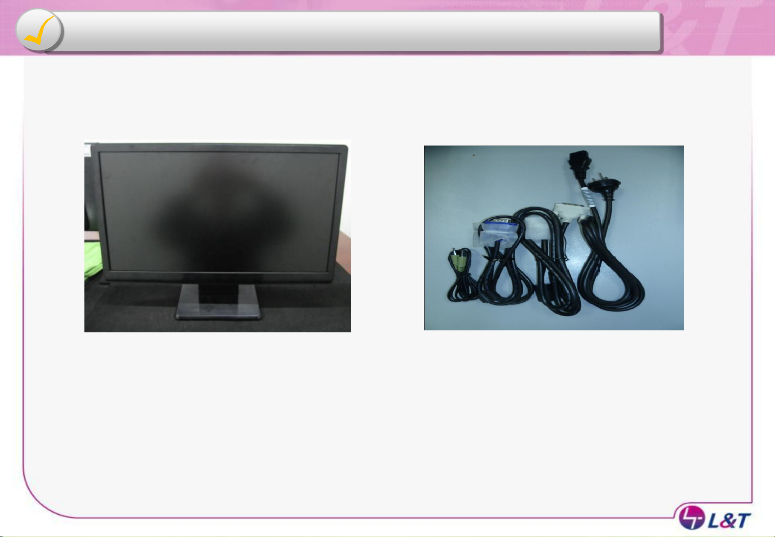
External Electric Cables Dissecting Process
AUDIO Cable
D-SUB &DVI Cable
1.Remove Cable From Display Head. 2.Dissecting to Complete.
Power Cable
2
Page 5
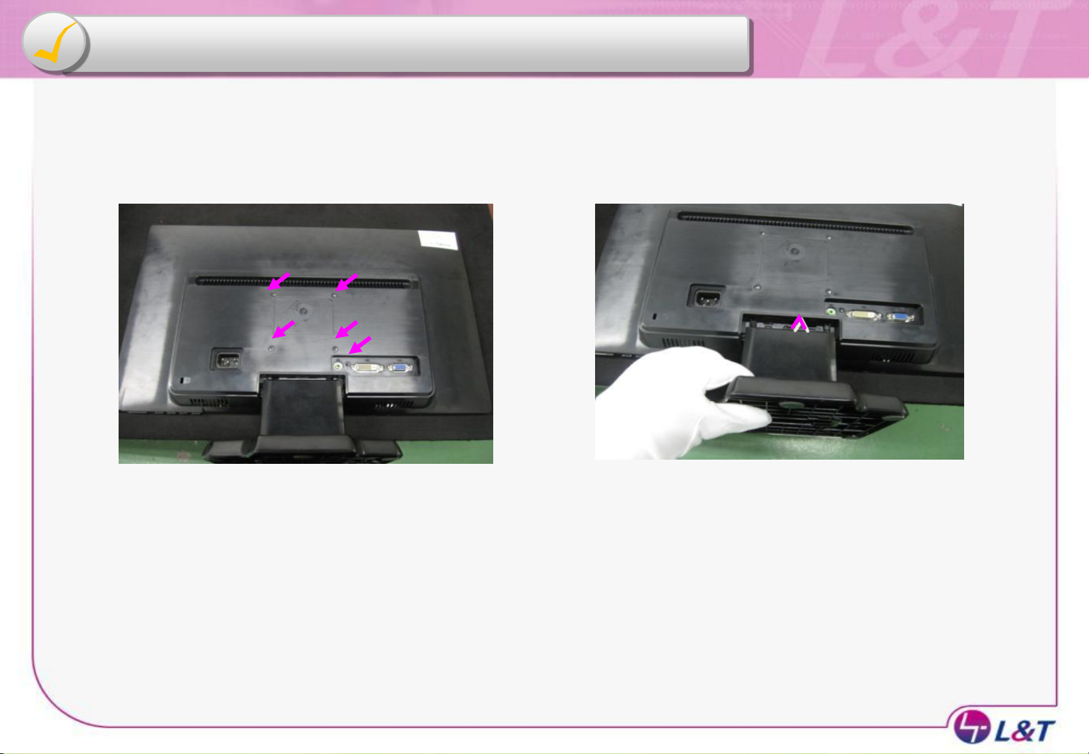
Remove Stand Base From Display
2
3
4 1
5
3
1.Take Screw(*5) from Rear Cover.
2. Demount Stand & Remove Stand Base Form
Display.
Page 6
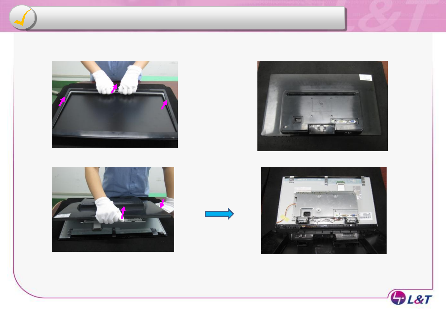
Remove Rear Cover From Display Head
1
2
1.Both Hands Upwardly Pull Up.
3
2.Turn over Display Head.
4
3. Toward the arrowhead , take the
Rear Cover from the Front Cover.
4. Remove Rear Cover.
Page 7

Remove KEPC board From Front Cover
5
1. Take the KEPC assembly from the Front
Cover.
2.Remove Connector off from KEPC board
and disassemble KEPC assembly .
Page 8

Remove Mainframe &Panel
1. Remove Connector off from Power
board & Panel.
2.Remove the Conductive Tape from
the Mainframe.
6
3.Remove Mainframe & Panel.
4.Remove the connecting wire
Page 9
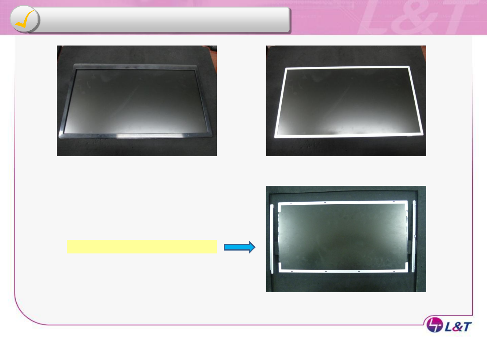
Remove Front Cover &Panel
1.Turn over Panel, and remove the Front
Cover off from Panel.
2. Dissecting to complete.
7
Direct at the LNT panel Modle
3. Demount BRACKET-L & BRACKET-R Form
LNT panel.
Page 10

Take Screw off From Mainframe Assembly
1.Take Screw(*4 or 2) from Mainframe.
2.Tear off Mylar form mainframe
8
3. Take Screw(*6) from Power Bd & Main Bd .
Page 11

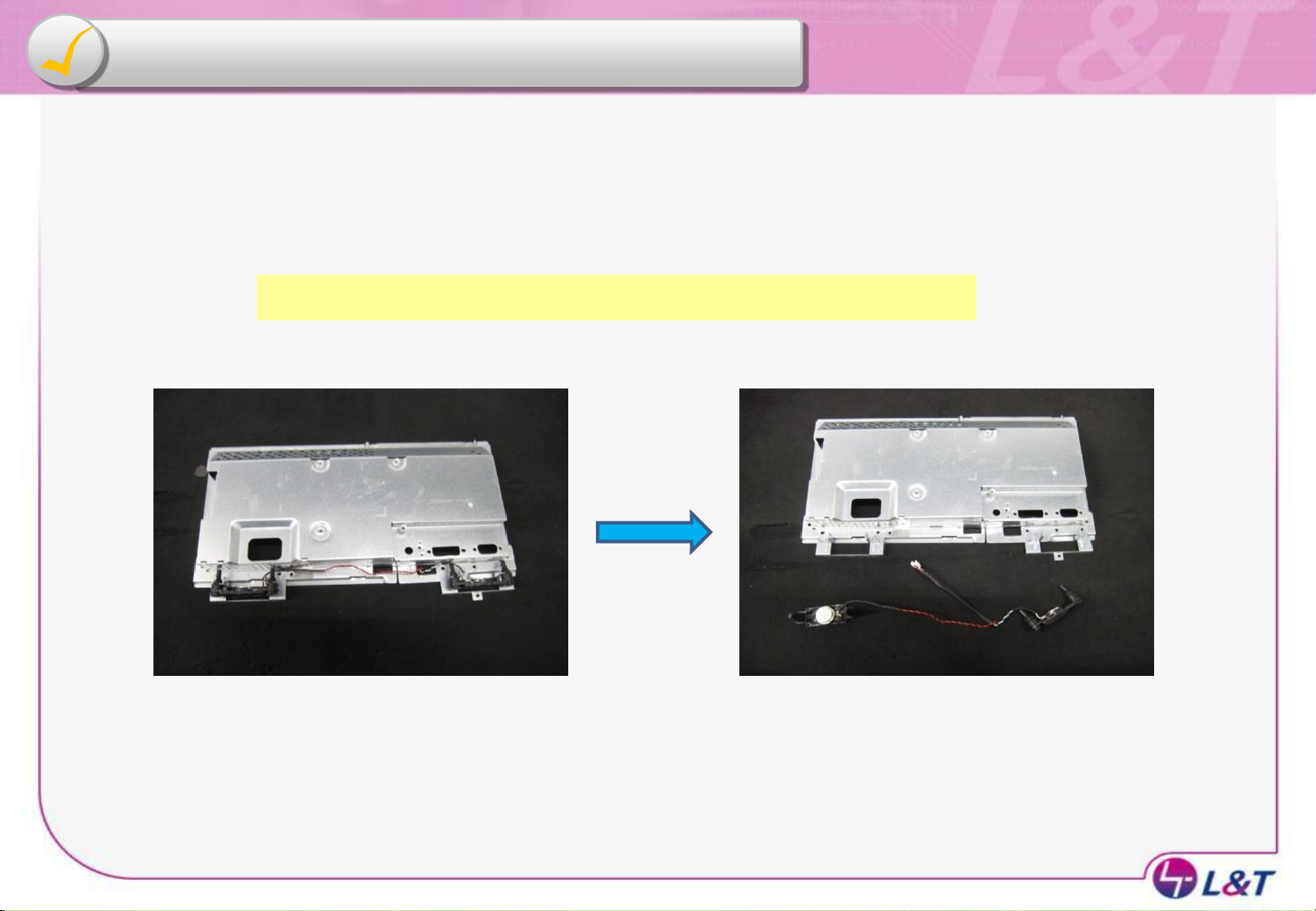
Remove Mainframe & Barod
1. Direct at the Modle have Audio
function:
Remove the Audio Connector off from
Power Bd .
9
2.Remove the Power Bd & Main Bd off
from Mainframe.
3.Remove the connecting wire off from
Power Bd & Main Bd .
Page 12
Remove Audio & Mainframe
Direct at the Modle have Audio function:
10
1. Take Mainframe, remove the Audio
off from Mainframe.
2. Dissecting to complete.
Page 13
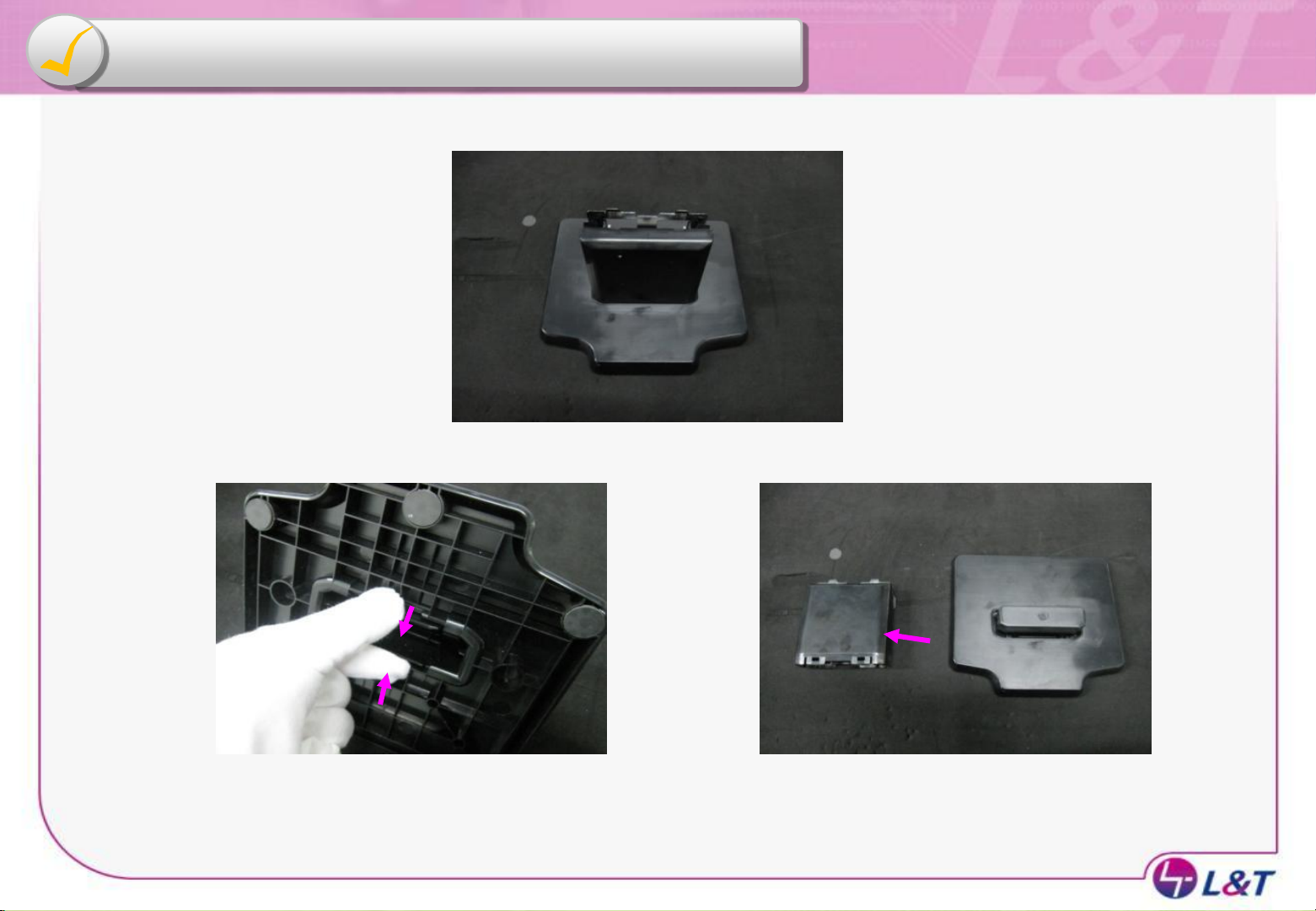
Remove Stand & Base
1.Take Stand assembly.
11
2. Pinch the limit RIB of Base.
3. Remove the Stand off from the
Base.
Page 14

Remove hinge & stand
12
1. Take screw(*2) off, and remove the Hinge
off from the Stand.
2. Dissecting to complete.
Page 15

Thank You
13
 Loading...