

Page 1

HP TX1 POS Solution 200
Maintenance and Service Guide
Page 2

© Copyright 2015 Hewlett-Packard
Development Company, L.P.
Bluetooth is a trademark owned by its
proprietor and used by Hewlett-Packard
Company under license. Intel and Core are U.S.
registered trademarks of Intel Corporation.
Microsoft and Windows are U.S. registered
trademarks of Microsoft Corporation. SD Logo
is a trademark of its proprietor.
The information contained herein is subject to
change without notice. The only warranties for
HP products and services are set forth in
the express warranty statements
accompanying such products and services.
Nothing herein should be construed as
constituting an additional warranty. HP shall
not be liable for technical or editorial errors or
omissions contained herein.
First Edition: September 2015
Document Part Number: 839958-001
Product notice
This guide describes features that are common
to most models. Some features may not be
available on your tablet.
Not all features are available in all editions of
Windows 8. This tablet may require upgraded
and/or separately purchased hardware, drivers,
and/or software to take full advantage of
Windows 8 functionality. See for
http://www.microsoft.com details.
Software terms
By installing, copying, downloading, or
otherwise using any software product
preinstalled on this tablet, you agree to be
bound by the terms of the HP End User License
Agreement (EULA). If you do not accept these
license terms, your sole remedy is to return the
entire unused product (hardware and software)
within 14 days for a refund subject to the
refund policy of your place of purchase.
For any further information or to request a full
refund of the tablet, please contact your local
point of sale (the seller).
Page 3

Safety warning notice
WARNING! To reduce the possibility of heat-related injuries or of overheating the device, do not place
the device directly on your lap or obstruct the device air vents. Use the device only on a hard, at surface. Do
not allow another hard surface, such as an adjoining optional printer, or a soft surface, such as pillows or rugs
or clothing, to block airow. Also, do not allow the AC adapter to contact the skin or a soft surface, such as
pillows or rugs or clothing, during operation. The device and the AC adapter comply with the user-accessible
surface temperature limits dened by the International Standard for Safety of Information Technology
Equipment (IEC 60950).
iii
Page 4

iv Safety warning notice
Page 5

Table of contents
1 Setting up the system .................................................................................................................................... 1
2 HP ElitePad 1000 G2 product description ......................................................................................................... 5
3 Tablet external component identication ........................................................................................................ 7
Finding your hardware and software information ................................................................................................ 7
Locating hardware ............................................................................................................................... 7
Locating software ................................................................................................................................ 7
Front ....................................................................................................................................................................... 8
Rear ........................................................................................................................................................................ 9
Top ........................................................................................................................................................................ 10
Bottom ................................................................................................................................................................. 11
Labels ................................................................................................................................................................... 11
4 Illustrated parts catalog .............................................................................................................................. 12
HP TX1 POS Solution 200 .................................................................................................................................... 12
Locating the serial number, product number, and model number ..................................................................... 13
Tablet major components .................................................................................................................................... 14
Miscellaneous tablet parts .................................................................................................................................. 16
Power components .............................................................................................................................................. 17
Sequential part number listing ........................................................................................................................... 18
5 Removal and replacement preliminary requirements ..................................................................................... 23
Tools required ...................................................................................................................................................... 23
Service considerations ......................................................................................................................................... 23
Plastic parts ....................................................................................................................................... 23
Cables and connectors ...................................................................................................................... 23
Grounding guidelines ........................................................................................................................................... 24
Electrostatic discharge damage ........................................................................................................ 24
Packaging and transporting guidelines .......................................................................... 25
Workstation guidelines ................................................................................ 25
6 Removal and replacement procedures – tablet ............................................................................................... 27
Display assembly ................................................................................................................................................. 27
NFC antenna ......................................................................................................................................................... 34
v
Page 6

WWAN module ..................................................................................................................................................... 35
WLAN module ...................................................................................................................................................... 37
Microphones ........................................................................................................................................................ 39
Rear-facing webcam ............................................................................................................................................ 40
Power button board ............................................................................................................................................. 41
Volume button board ........................................................................................................................................... 43
Audio jack board .................................................................................................................................................. 46
Vibrator module ................................................................................................................................................... 47
Battery ................................................................................................................................................................. 48
System board ....................................................................................................................................................... 50
Forward-facing webcam ...................................................................................................................................... 54
Slot cover ............................................................................................................................................................. 55
Docking connector cable ..................................................................................................................................... 56
WLAN antenna ..................................................................................................................................................... 58
WWAN/GPS auxiliary antenna ............................................................................................................................. 60
Speakers .............................................................................................................................................................. 62
7 Using Setup Utility (BIOS) ............................................................................................................................. 64
Starting Computer Setup ..................................................................................................................................... 64
Updating the BIOS ................................................................................................................................................ 64
Determining the BIOS version ........................................................................................................... 64
Downloading a BIOS update .............................................................................................................. 65
8 Tablet specications .................................................................................................................................... 66
9 Backup and recovery .................................................................................................................................... 67
Backing up your information ............................................................................................................................... 67
Performing a system recovery ............................................................................................................................ 67
Using the Windows recovery tools .................................................................................................... 68
Using f11 recovery tools ................................................................................................................... 68
Changing the boot device order ........................................................................................................ 69
Using Windows Refresh or Windows Reset ...................................................................................... 69
10 Power cord set requirements ...................................................................................................................... 70
Requirements for all countries ............................................................................................................................ 70
Requirements for specic countries and regions ............................................................................................... 71
11 Recycling .................................................................................................................................................. 72
Index ............................................................................................................................................................. 73
vi
Page 7
1 Setting up the system
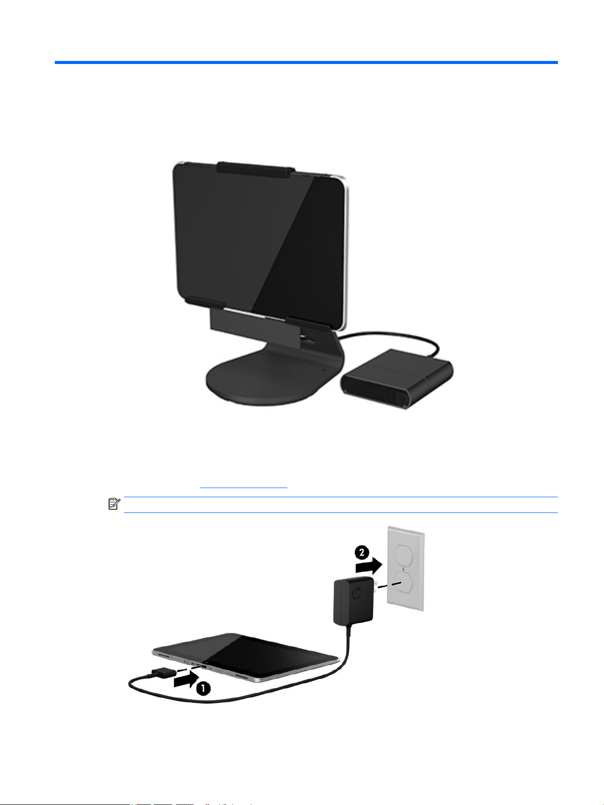
1. Set up the tablet. After charging the battery, press and hold the power button for up to 5 seconds until
the HP logo is displayed. Follow the on-screen instructions to select a language, a wireless network, and
a Microsoft account. Note: If you do not have a Microsoft account, you can create one now. To view the
set up video go to www.hp.com/go/pos.
NOTE: After setting up the tablet, you must power o the tablet before connecting the components.
1
Page 8
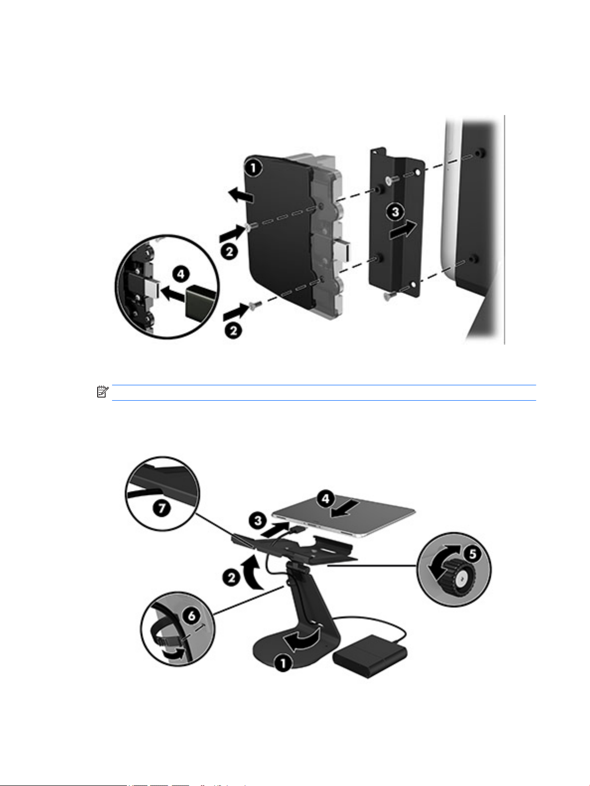
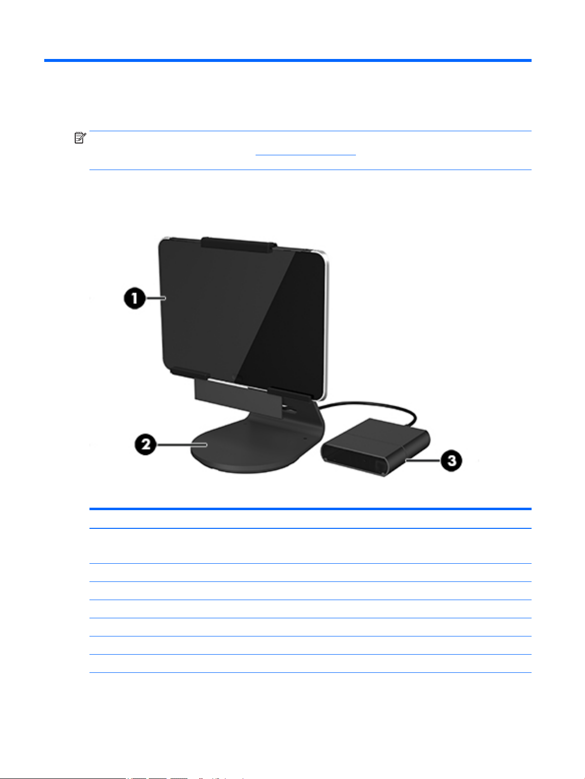
2. (optional) Connect the HP ngerprint reader or HP MSR to the bracket (1) and (2). Then connect to the
right or left side of the stand, using the included screws (3). Connect a USB cable to the component (4),
run the cable through the opening in the stand and through the cable clip and then connect the other
end to the adapter. See (1) and (2) in step 3 below.
3. Connect the tablet to the stand and to the HP ElitePad Connectivity and Smart AC Adapter, as follows.
Route the adapter cable through the opening in the stand (1) and through the cable clip (2).
NOTE: To open the cable clip, gently squeeze it to unhinge the right side.
Connect the adapter cable to the port on the bottom of the tablet (3).
Insert the tablet into the stand (4), and tighten the thumb screw to secure the tablet in the stand (5).
2 Chapter 1 Setting up the system
Page 9
4. Secure the cables. Close the cable clip (6) and press the cable into the relief notch on the bottom of the
stand (7).
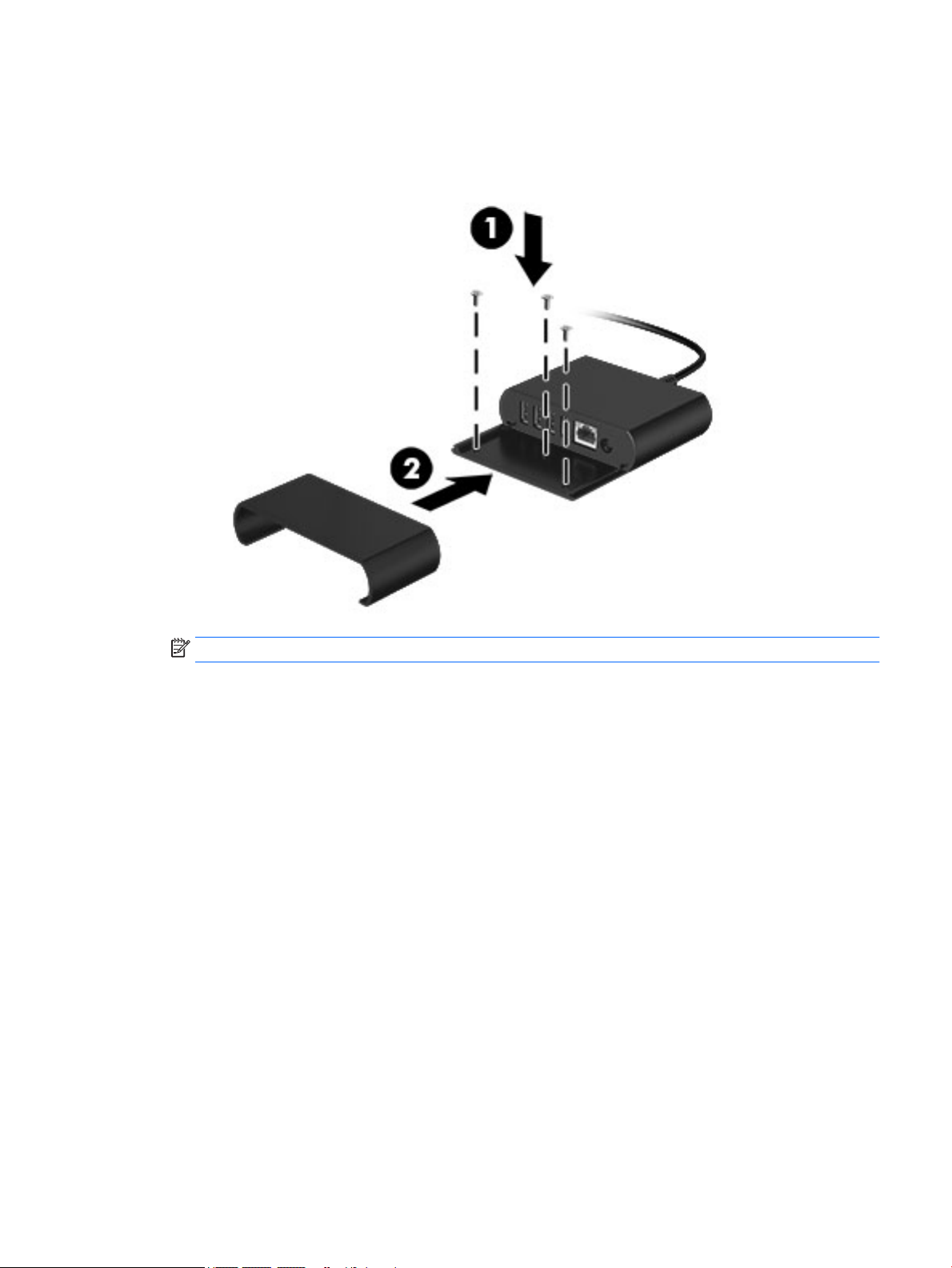
5. (optional) Mount the connectivity hub to a countertop.
NOTE: Screws are not included.
3
Page 10
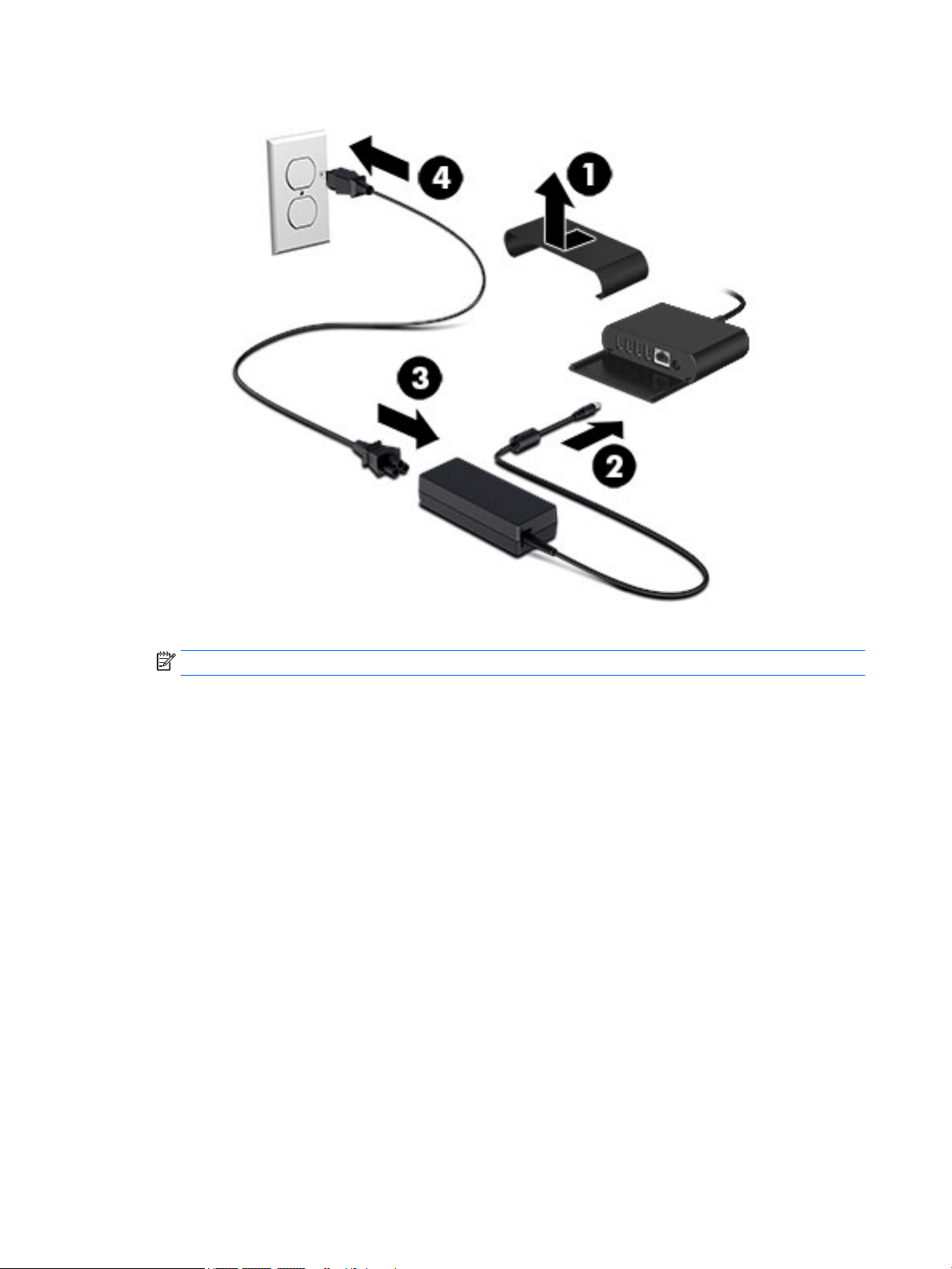
6. Connect the power supply to the adapter.
7. Connect network cable and USB devices. Replace the port cover and turn on the tablet.
NOTE: The HP ElitePad Connectivity and Smart AC Adapter must have power to operate.
4 Chapter 1 Setting up the system
Page 11

2 HP ElitePad 1000 G2 product description
Category Description
Product Name HP ElitePad 1000 G2
Processor Intel® Atom z3795 1.60-GHz processor (core burst up to 2.39-GHz), 1.60-GHz front-side bus (FSB),
2.0-MB L2 cache, up to 778-MHz graphics burst frequency, soldered to system board
Graphics Intel HD Graphics
Panel 10.1-in., WUXGA (1900×1200), UWVA, 50% CG, 400-nit, active pen and MultiTouch capacitive
digitizer, chemically-strengthened glass with anti-smudge
Memory On-board 1067-MHz, LPDDR3, 4096-MB memory (soldered to system board); system supports a
4096-MB × 1 (4 pieces, 128 MB × 32 chips) conguration
Primary storage 128- or 64-GB embedded MultiMedia Card (eMMC), soldered to the system board
Optical drive No internal optical drive or USB-powered optical drive is supported
Audio and video 2 integrated stereo speakers, each 1.5 W
HD Audio
DTS+ sound
2 digital microphones
2 xed, integrated webcams (2.1-MP front-facing webcam; 8.0-MP rear-facing webcam with LED
ash)
Ethernet No Ethernet support
Wireless Integrated wireless local area network (WLAN) options by way of wireless module
Integrated WLAN antennas
Support for the Broadcom BCM43241 802.11abgn 2x2 Wi-Fi + BT 4.0 Combo Adapter
Wireless (continued) Integrated wireless wide area network (WWAN) options by way of wireless module
Integrated world-wide/5-band WWAN antennas
Secured by subscriber identity module (SIM)
Support for the following WWAN formats:
●
HP hs3110 HSPA+ Mobile Broadband Module
●
HP lt4111 LTE/EV-DO/HSPA+ Gobi 4G Module
●
HP lt4112 LTE/HSPA+ Gobi 4G Module
●
HP lt4225 LTE/EV-DO Gobi 4G Module
●
HP lt4226 LTE/HSPA+ Gobi 4G Module
Support for no WWAN option
Integrated near eld communication (NFC) module and antennas
External media cards Flash Media slot (with push-push technology) supporting microHCSD cards up to 64-GB
Ports
●
Audio-in (mono microphone)/audio-out (stereo headphone) combo jack
5
Page 12

Category Description
●
HP ElitePad 1000-proprietary docking connector
Sensors
Docking HP ElitePad-proprietary dock with 4 standard 2.0 USB ports, VGA port, HDMI-out port, audio in/out
Keyboard/pointing devices No integrated keyboard or TouchPad
Power requirements Support for an HP ElitePad-proprietary 10-W AC adapter (RC, V, 3-wire, wall-mount); connector on
Support for 2-cell, 30-Wh, 4.0-Ah, Li-ion battery
Security Support for trusted platform module (TPM; Inneon TPM is SLB9656VQ1.2FW4.32)
Operating system Preinstalled:
●
Accelerometer + eCompass
●
Ambient light sensor
●
Gyroscope
●
Haptics
jacks, and HP Smart AC adapter connector (40-W HP Smart AC adapter and power cord included)
Support for USB- or Bluetooth-connected external keyboard and mouse
AC Adapter connects to the tablet through the docking connector
●
Microsoft Windows 8.1 Professional 64-bit
6 Chapter 2 HP ElitePad 1000 G2 product description
Page 13

3 Tablet external component identication
Finding your hardware and software information
Locating hardware
To nd out what hardware is installed on the tablet:
1. On the Start screen, type control panel, and then select Control Panel.
2. Select System and Security, and then in the System area, tap Device Manager. A list displays all the
devices installed on the tablet.
Locating software
To nd out what software is installed on the tablet:
▲
Swipe from the left until the arrow appears, and then tap the arrow in the lower-left corner of
the screen.
– or –
Swipe up from the bottom to display the Apps screen.
Finding your hardware and software information 7
Page 14
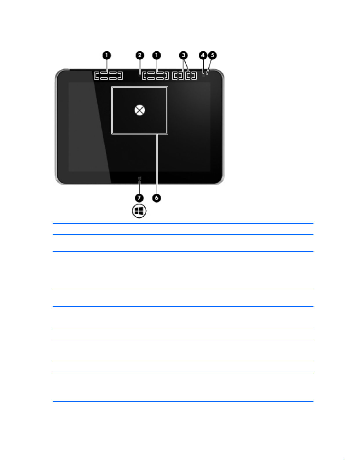
Front
Item Component Description
(1) WWAN antennas (2)* (select models only) Send and receive wireless signals to communicate
with WWANs.
(2) Front webcam Records video and captures still photographs.
To use the webcam, tap the YouCam tile on the Start screen,
or swipe from the right edge of the touch screen to display
the charms, tap Search, and then tap the search box. In the
search box, type c, and then tap CyberLink YouCam.
(3) WLAN antennas (2)* Send and receive wireless signals to communicate
with WLANs.
(4) Ambient light sensor The ambient light sensor automatically adjusts the
display brightness based on the lighting conditions in
your environment.
(5) Webcam status light (front) On: The webcam is on.
(6) Near Field Communications (NFC) tapping area Allows you to touch an NFC-compatible device to this area to
wirelessly connect and communicate with the tablet and
transfer data back and forth.
(7) Windows button Displays the Start screen.
*The antennas are not visible on the outside of the tablet. For optimal transmission, keep the areas immediately around the antennas
free from obstructions. To see wireless regulatory notices, see the section of the Regulatory, Safety, and Environmental Notices that
applies to your country or region. To access the user guides, tap the HP Support Assistant app on the Start screen, tap My computer,
and then tap User guides.
8 Chapter 3 Tablet external component identication
Page 15
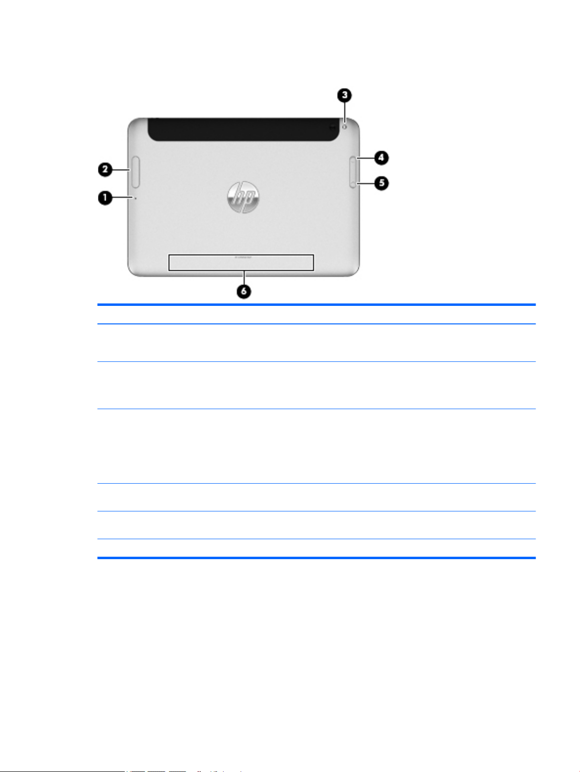
Rear
Item Component Description
(1) Micro SD Card Reader/Micro SIM slot access
hole
(2) Memory card reader/Micro SIM slot Reads optional micro memory cards that store, manage,
(3) Rear webcam Records video, captures still photographs, and allows video
(4) Volume up button To increase speaker volume, press the top edge of
(5) Volume down button To decrease speaker volume, press the bottom edge of
(6) Regulatory information Displays regulatory information (select models only).
Allows you to insert the end of a paper clip to open the
access door to insert or remove a micro SD card or micro SIM
module.
share, or access information. and supports an optional
wireless micro subscriber identity module (SIM) (select
models only).
conferences and online chat by means of streaming video.
To use the webcam, tap the YouCam tile on the Start screen,
or swipe from the right edge of the touch screen to display
the charms, tap Search, and then tap the search box. In the
search box, type c, and then tap CyberLink YouCam.
the button.
the button.
Rear 9
Page 16

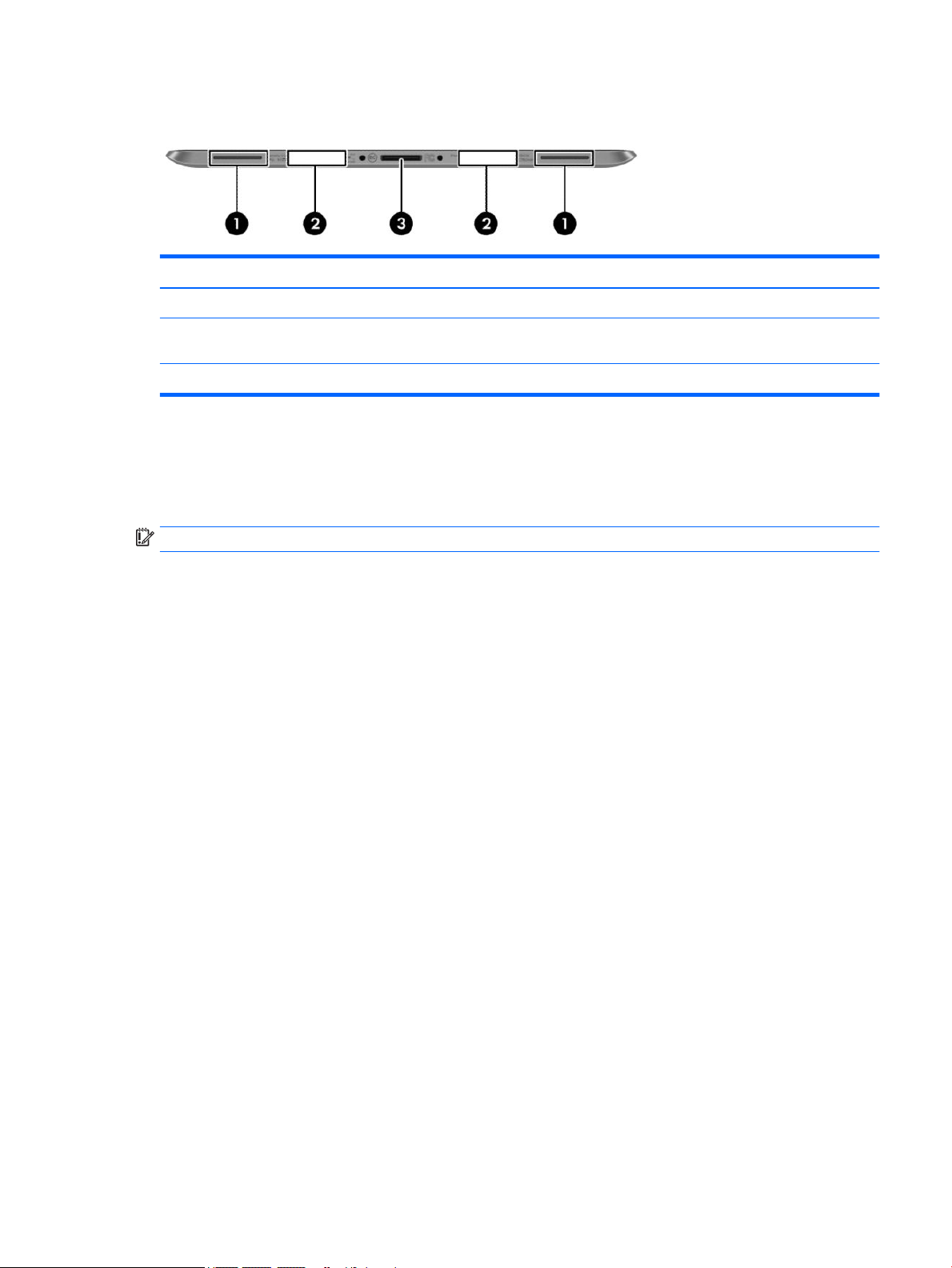
Top
Item Component Description
(1) Audio-out (headphone) jack/Audio-in
(microphone) jack
(2) Autorotate switch When the tablet is on, slide the autorotate switch to lock the
(3) Integrated microphones (2) Record sound.
(4) Power button
Produces sound when connected to optional powered stereo
speakers, headphones, earbuds, a headset, or television
audio. Also connects an optional headset microphone.
WARNING! To reduce the risk of personal injury, adjust the
volume before putting on headphones, earbuds, or a
headset. For additional safety information, refer to the
Regulatory, Safety, and Environmental Notices. To access the
user guides, tap the HP Support Assistant app on the Start
screen, tap My computer, and then tap User guides.
NOTE: When a device is connected to the jack, the
computer speakers are disabled.
NOTE: Be sure that the device cable has a 4-conductor
connector that supports both audio-out (headphone) and
audio-in (microphone).
autorotate feature of the display. To unlock the autorotate
feature, slide the switch again.
– or –
Swipe from the right edge of the touch screen to display the
charms, tap Settings, tap the screen icon, and then tap the
autorotate icon. To unlock the autorotate feature, tap the
autorotate icon again.
●
When the tablet is o, press the button to turn on
the tablet.
●
When the tablet is on, press the button briey to
initiate Sleep.
●
When the tablet is in the Sleep state, press the button
briey to exit Sleep.
CAUTION: Pressing and holding down the power button will
result in the loss of unsaved information.
If the tablet has stopped responding and Windows shutdown
procedures are ineective, press and hold the power button
for at least 5 seconds to turn o the tablet.
Swipe from the right edge of the touch screen to display the
charms, tap Search, and then tap the search box. In the
search box, type power, tap Power and sleep settings, and
then select Power and sleep from the list of applications.
10 Chapter 3 Tablet external component identication
Page 17
Bottom
Labels
The labels aixed to the tablet provide information you may need when you troubleshoot system problems or
travel internationally with the tablet.
IMPORTANT: All labels described in this section are located on the back of the tablet.
●
Item Component Description
(1) Speakers (2) Produce sound.
(2) Product and regulatory information Displays product and regulatory information
(select models only).
(3) Docking connector Connects an AC adapter or an optional docking device.
Serial number and product number are located on the bottom edge of the tablet and/or aixed to the
back of the tablet. When contacting support, you will probably be asked for the serial number, and
possibly for the product number or the model number. Locate these numbers before you contact
support.
●
Regulatory label(s)—Provide(s) regulatory information about the tablet. Regulatory markings for your
country or region are located on the back of the tablet. For regulatory identication purposes, your
product is assigned a Regulatory Model Number. The regulatory number should not be confused
with the marketing name or product numbers. For more information, see the Quick Start guide included
with your tablet.
●
Wireless certication label(s)—Provide(s) information about optional wireless devices and the approval
markings for the countries or regions in which the devices have been approved for use.
Bottom 11
Page 18
4 Illustrated parts catalog
NOTE: HP continually improves and changes product parts. For complete and current information on
supported parts for your computer, go to http://partsurfer.hp.com, select your country or region, and then
follow the on-screen instructions.
HP TX1 POS Solution 200
Item Component Spare part number
(1) HP ElitePad 1000 G2 (whole unit)
NOTE: Spared as a whole unit using an advanced exchange strategy.
For use in the United States 792095-001
For use in the Canada 792095-DB1
(2) Stand 779204-001
(3) HP ElitePad Connectivity and Smart AC Adapter 824990-001
* Cable clip, TX 1 200 stand (not illustrated) 781033-001
* Screw, TX 1 200 stand (not illustrated) 781032-001
12 Chapter 4 Illustrated parts catalog
Page 19
Item Component Spare part number
* HP Magnetic Stripe Reader (not illustrated) K1K15AA
* HP Fingerprint Reader (not illustrated) QZ672AA
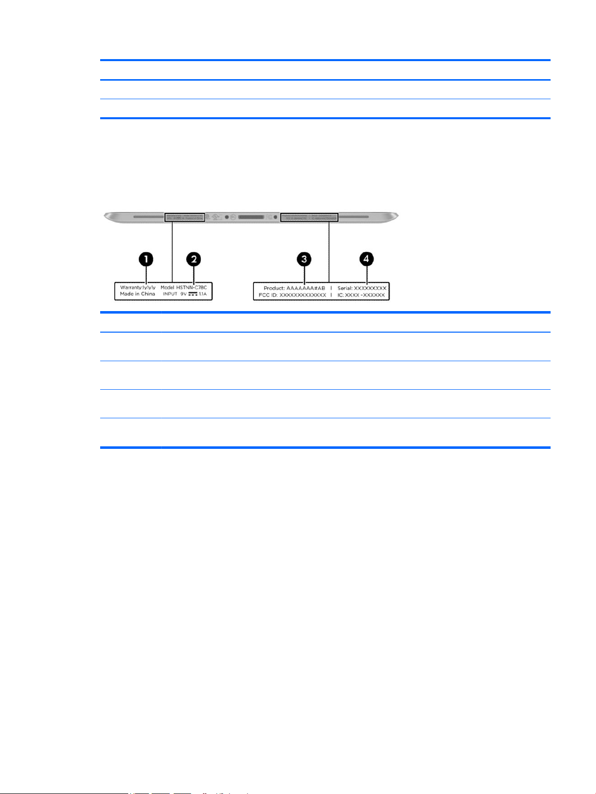
Locating the serial number, product number, and model number
When ordering parts or requesting information, provide the tablet serial number and model number provided
on the service tag.
Item Description Function
(1) Warranty period This number describes the duration of the warranty
period for the tablet.
(2) Model description This is the alphanumeric identier used to locate
documents, drivers, and support for the tablet.
(3) Product name This is the product name aixed to the front of
the tablet.
(4) Serial number (s/n) This is an alphanumeric identier that is unique to each
product.
Locating the serial number, product number, and model number 13
Page 20
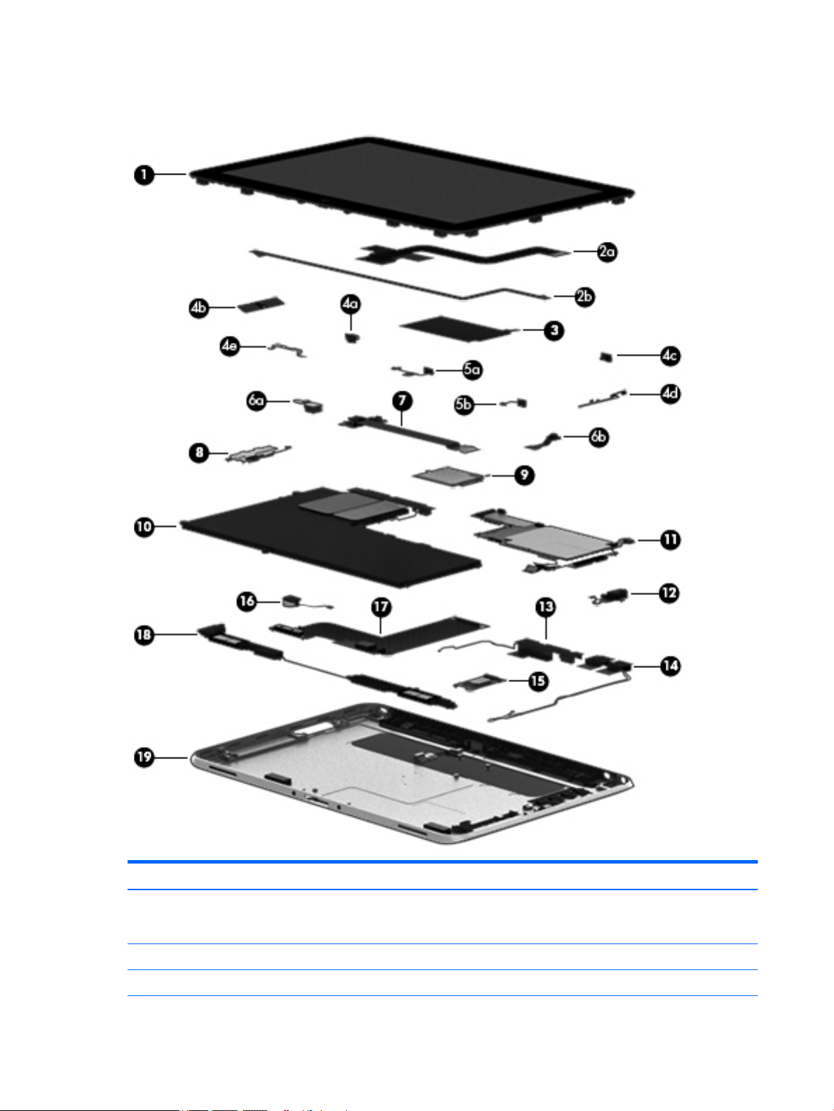
Tablet major components
Item Component Spare part number
(1) Display assembly (10.1-in., WUXGA (1900×1200), UWVA, 50% CG, 400-nit, active pen and
MultiTouch capacitive digitizer, chemically-strengthened glass with anti-smudge; includes
display panel, display LVDS cable, TouchScreen cable, and display panel support rubber)
Display Cable Kit, includes: 747625-001
(2a) TouchScreen cable
14 Chapter 4 Illustrated parts catalog
747658-001
Page 21

Item Component Spare part number
(2b) Display LVDS cable
(3) NFC antenna (includes double-sided adhesive) 747633-001
Button Kit, includes: 747634-001
(4a) Power button actuator
(4b) Volume button actuator
(4c) Autorotate switch actuator
(4d) Slot cover hardware (slot cover, retention bracket, spring bracket)
(4e) Docking connector bracket
Webcam/Microphone Kit, includes: 762828-001
(5a) Left microphone
(5b) Right microphone
(6a) Rear-facing webcam
(6b) Front-facing webcam
(7) Power button board (includes cable)
For use only on tablet models equipped with the Windows 8 Professional operating system 753976-601
For use only on tablet models equipped with the Windows 8 Standard operating system 753976-501
For use only on tablet models equipped with a non-Windows 8 operating system 753976-001
(8) Volume button board (includes bracket and cable) 759031-001
(9) WWAN module:
HP hs3110 HSPA+ Mobile Broadband Module 748599-005
HP lt4111 LTE/EV-DO/HSPA+ Gobi 4G Module 704030-005
HP lt4112 LTE/HSPA+ Gobi 4G Module 740011-005
HP lt4225 LTE/EV-DO Gobi 4G Module 736676-005
HP lt4226 LTE/HSPA+ Gobi 4G Module 736675-005
(10) 2-cell, 30-Wh, 4.0-Ah, Li-ion battery (includes battery cable and WWAN/GPS main
transceiver and antenna cable)
(11) System board equipped with an Intel Atom z3795 quad core 1.60-GHz processor (burst up to 2.39-GHz; 2.0-MB L2 cache),
and 4096-MB of system memory (includes processor, memory, and eMMC)
Equipped with 128-GB of eMMC primary storage 753741-001
Equipped with 64-GB of eMMC primary storage 753740-001
(12) Audio jack board (includes audio jack and cable) 747627-001
Antenna Kit, includes:
728558-005
(13) WWAN/GPS auxiliary antenna (includes auxiliary antenna cable and transceiver)
(14) WLAN antenna (includes WLAN main and auxiliary antenna cables and transceivers)
For use only in European countries and regions 767884-001
Tablet major components 15
Page 22

Item Component Spare part number
For use only in Japan 767885-001
For use only in the United States 767883-001
(15) Broadcom BCM43241 802.11abgn 2x2 Wi-Fi + BT 4.0 Combo Adapter 723677-005
(16) Vibrator module (includes cable, double-sided adhesive, plastic cover) 747630-001
(17) Docking connector cable (includes cable and double-sided adhesive) 747631-001
(18) Speakers (include left and right speakers and cables) 747629-001
(19) Bottom case (includes the power button actuator and the slot cover and brackets) 747628-001
Miscellaneous tablet parts
Component Spare part number
HP ElitePad Service Tool (includes suction cup) 714222-001
HP ElitePad suction cup 714223-001
HP executive tablet pen 716117-001
Screw Kit for use only with the tablet 709461-001
16 Chapter 4 Illustrated parts catalog
Page 23
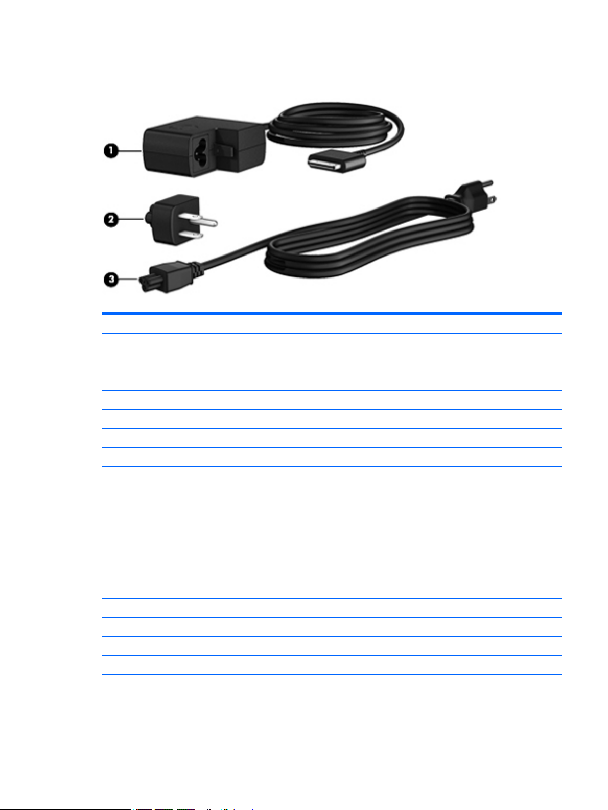
Power components
Item Component Spare part number
(1) 10-W AC adapter for use only on the HP ElitePad 1000 G2 (RC, V, 3-wire, wall-mount) 686120-001
(2) Duck head power adapter:
For use in Argentina 755184-D01
For use in Australia 755184-011
For use in Brazil 755184-201
For use in Denmark 755184-081
For use in Europe 755184-021
For use in India 755184-D61
For use in Israel 755184-BB1
For use in Italy 755184-061
For use in the People's Republic of China 755184-371
For use in South Africa 755184-AR1
For use in Switzerland 755184-BG1
For use in the United Kingdom and Singapore 755184-031
For use in the United States 755184-001
(3) Power cord (3-pin, black, 1.83-m):
For use in Argentina 490371-D01
For use in Australia 490371-011
For use in Brazil 490371-202
For use in Europe 490371-021
For use in India 490371-D61
Power components 17
Page 24

(continued)
Item Component Spare part number
For use in Israel 490371-BB1
For use in Italy 490371-061
For use in Japan 490371-291
For use in North America 490371-001
For use in the People's Republic of China 490371-AA1
For use in South Africa 490371-AR1
For use in South Korea 490371-AD1
For use in Switzerland 490371-111
For use in Taiwan 490371-AB1
For use in the United Kingdom and Singapore 490371-031
Card Reader Cover Kit (not illustrated) 747632-001
HP Mobile Connect SIM (not illustrated) 714749-001
Screw Kit for use only on the HP ElitePad 1000 G2 (not illustrated) 753735-001
Tape Support Kit 762827-001
Sequential part number listing
Spare part number Description
490371-001 Power cord for use in North America (3-pin, black, 1.83-m)
490371-011 Power cord for use in Australia (3-pin, black, 1.83-m)
490371-021 Power cord for use in Europe (3-pin, black, 1.83-m)
490371-031 Power cord for use in the United Kingdom and Singapore (3-pin, black, 1.83-m)
490371-061 Power cord for use in Italy (3-pin, black, 1.83-m)
490371-111 Power cord for use in Switzerland (3-pin, black, 1.83-m)
490371-202 Power cord for use in Brazil (3-pin, black, 1.83-m)
490371-291 Power cord for use in Japan (3-pin, black, 1.83-m)
490371-AA1 Power cord for use in the People's Republic of China (3-pin, black, 1.83-m)
490371-AB1 Power cord for use in South Korea (3-pin, black, 1.83-m)
490371-AD1 Power cord for use in Taiwan (3-pin, black, 1.83-m)
490371-AR1 Power cord for use in South Africa (3-pin, black, 1.83-m)
490371-BB1 Power cord for use in Israel (3-pin, black, 1.83-m)
490371-D01 Power cord for use in Argentina (3-pin, black, 1.83-m)
490371-D61 Power cord for use in India (3-pin, black, 1.83-m)
18 Chapter 4 Illustrated parts catalog
Page 25

Spare part number Description
686120-001 10-W AC adapter (RC, V, 3-wire, wall-mount)
687946-001 2-cell, 21-Wh, 2.96-Ah, Li-ion battery for use only on the Retail Jacket
693717-001 40-W HP Smart AC adapter for use only with the docking station (RC, V, 3-wire)
695551-001 HDMI/VGA adapter cable
695552-001 USB adapter cable
695553-001 HP Smart AC adapter cable
695554-001 Card Reader adapter
695555-001 Ethernet adapter cable
695556-001 Serial adapter cable
704030-001 HP lt4111 LTE/EV-DO/HSPA+ Gobi 4G Module
708621-001 Docking station
708772-001 Rugged carrying case
709462-001 Slate jacket with battery slot (includes battery)
714222-001 HP ElitePad Service Tool (includes suction cup)
714223-001 HP ElitePad suction cup
714297-001 Slate jacket without battery slot
714749-001 HP Mobile Connect SIM
723677-005 Broadcom BCM43241 802.11abgn 2x2 Wi-Fi + BT 4.0 Combo Adapter
724301-001 Jacket keyboard for use in the United States
724301-031 Jacket keyboard for use in the United Kingdom and Singapore
724301-041 Jacket keyboard for use in Germany
724301-051 Jacket keyboard for use in France
724301-061 Jacket keyboard for use in Italy
724301-071 Jacket keyboard for use in Spain
724301-081 Jacket keyboard for use in Denmark
724301-091 Jacket keyboard for use in Norway
724301-131 Jacket keyboard for use in Portugal
724301-141 Jacket keyboard for use in Turkey
724301-151 Jacket keyboard for use in Greece
724301-161 Jacket keyboard for use in Latin America
724301-171 Jacket keyboard for use in Saudi Arabia
724301-201 Jacket keyboard for use in Brazil
724301-211 Jacket keyboard for use in Hungary
724301-251 Jacket keyboard for use in Russia
Sequential part number listing 19
Page 26

Spare part number Description
724301-261 Jacket keyboard for use in Bulgaria
724301-271 Jacket keyboard for use in Romania
724301-281 Jacket keyboard for use in Thailand
724301-291 Jacket keyboard for use in Japan
724301-A41 Jacket keyboard for use in Belgium
724301-AB1 Jacket keyboard for use in Taiwan
724301-AD1 Jacket keyboard for use in South Korea
724301-B31 Jacket keyboard for use in the Netherlands
724301-B71 Jacket keyboard for use in Sweden and Finland
724301-BA1 Jacket keyboard for use in Slovenia
724301-BB1 Jacket keyboard for use in Israel
724301-BG1 Jacket keyboard for use in Switzerland
724301-D61 Jacket keyboard for use in India
724301-DB1 Jacket keyboard for use in Canada
724301-DD1 Jacket keyboard for use in Iceland
724301-FL1 Jacket keyboard for use in the Czech Republic and Slovakia
724301-FP1 Jacket keyboard for use in Northwest Africa
728558-005 2-cell, 30-Wh, 4.0-Ah, Li-ion battery for use only on the HP ElitePad 1000 G2 tablet (includes battery
cable and WWAN/GPS main transceiver and antenna cable)
732251-001 Digital pen tethers (10)
736675-005 HP lt4226 LTE/HSPA+ Gobi 4G Module
736676-005 HP lt4225 LTE/EV-DO Gobi 4G Module
736679-001 HP ElitePad Jacket cover
739321-001 HP ElitePad USB3 adapter
740011-005 HP lt4112 LTE/HSPA+ Gobi 4G Module
742439-001 Retail Jacket handle
742440-001 Retail Jacket battery bay space saver
742441-001 Retail Jacket with battery
742442-001 Retail Jacket with battery bay space saver
742443-001 Retail Jacket Rubber Kit
742444-001 Security Jacket with screws
742446-001 Security Jacket with ngerprint reader and screws
742720-001 HP ElitePad dockable case
744025-001 Retail Jacket top cap (includes 4 captive screws, secured by C-rings)
744026-001 Retail Jacket credit card reader (includes cable)
20 Chapter 4 Illustrated parts catalog
Page 27

Spare part number Description
744027-001 Retail Jacket left-side credit card reader board
744028-001 Retail Jacket right-side credit card reader board
744029-001 Retail Jacket rear cover
744030-001 Retail Jacket front cover (includes bar code scanner lens and adhesive liner)
744031-001 Retail Jacket Cable Kit
744032-001 Retail Jacket system board (includes docking connector and USB port)
744033-001 Retail Jacket battery connector board (includes cable)
744034-001 Retail Jacket cable connector board
744035-001 Retail Jacket Screw Kit
744037-001 Retail Jacket bar code scanner module
744038-001 Retail Jacket Miscellaneous Rocker Button/Mount Kit
744039-001 Security Jacket card reader cover
744040-001 Security Jacket Rubber Kit
744041-001 Security Jacket rear cover (includes top cap release latch assembly)
744042-001 Security Jacket ngerprint reader
744043-001 Security Jacket card reader board
744044-001 Security Jacket system board
744045-001 Security Jacket Cables/Connectors Kit
744046-001 Security Jacket Screw Kit
744047-001 Security Jacket top cap (includes rubber trim)
744048-001 Security Jacket front cover
745882-001 Productivity Jacket Cable Retainer Kit
747625-001 Display Cable Kit (includes the display LVDS cable and the TouchScreen cable)
747627-001 Audio jack board (includes audio jack and cable)
747628-001 Bottom case (includes the power button actuator and the slot cover and brackets)
747629-001 Speakers (include left and right speakers and cables
747630-001 Vibrator module (includes cable, double-sided adhesive, plastic cover)
747631-001 Docking connector cable (includes double-sided adhesive)
747632-001 Smart Card Reader Cover Kit
747633-001 NFC antenna (includes double-sided adhesive)
747634-001 Button Kit (includes autorotate switch actuator, docking connector bracket, power button actuator, slot
cover hardware, and volume button actuator)
747658-001 Display assembly (10.1-in., WUXGA (1900×1200), UWVA, 50% CG, 400-nit, active pen and MultiTouch
capacitive digitizer, chemically-strengthened glass with anti-smudge; includes display panel, display LVDS
cable, TouchScreen cable, and display panel support rubber)
Sequential part number listing 21
Page 28

Spare part number Description
748599-005 HP hs3110 HSPA+ Mobile Broadband Module
751285-001 HP Executive Tablet pen
753735-001 Screw Kit for use only on the HP ElitePad 1000 G2
753740-001 System board equipped with an Intel Atom z3795 quad core 1.60-GHz processor (burst up to 2.39-GHz;
2.0-MB L2 cache), 4096-MB of system memory, and 64-GB of eMMC primary storage (includes processor,
memory, and eMMC)
753741-001 System board equipped with an Intel Atom z3795 quad core 1.60-GHz processor (burst up to 2.39-GHz;
2.0-MB L2 cache), 4096-MB of system memory, and 128-GB of eMMC primary storage (includes processor,
memory, and eMMC)
753976-001 Power button board for use only on tablet models equipped with a non-Windows 8 operating system
753976-501 Power button board for use only on tablet models equipped with the Windows 8 Standard
operating system
753976-601 Power button board for use only on tablet models equipped with the Windows 8 Professional
operating system
755184-001 Duck head power adapter for use only in the United States
755184-011 Duck head power adapter for use only in Australia
755184-021 Duck head power adapter for use only in Europe
755184-031 Duck head power adapter for use only in the United Kingdom and Singapore
755184-061 Duck head power adapter for use only in the Italy
755184-081 Duck head power adapter for use only in the Denmark
755184-201 Duck head power adapter for use only in Brazil
755184-371 Duck head power adapter for use only in the People's Republic of China
755184-AR1 Duck head power adapter for use only in South Africa
755184-BB1 Duck head power adapter for use only in Israel
755184-BG1 Duck head power adapter for use only in Switzerland
755184-D01 Duck head power adapter for use only in Argentina
755184-D61 Duck head power adapter for use only in India
756037-001 Security Jacket cover
759031-001 Volume button board (includes bracket and cable)
762827-001 Tape Support Kit
762828-001 Webcam/Microphone Kit (includes forward-facing and rear-facing webcams and microphones)
767882-001 3G antenna
767883-001 Antenna Kit for use only in the United States (includes WWAN/GPS auxiliary antenna cable and transceiver
and WLAN main and auxiliary antenna cables and transceivers)
767884-001 Antenna Kit for use only in European countries and regions (includes WWAN/GPS auxiliary antenna cable
and transceiver and WLAN main and auxiliary antenna cables and transceivers)
767885-001 Antenna Kit for use only in Japan (includes WWAN/GPS auxiliary antenna cable and transceiver and WLAN
main and auxiliary antenna cables and transceivers)
22 Chapter 4 Illustrated parts catalog
Page 29

5 Removal and replacement preliminary
requirements
Tools required
You will need the following tools to complete the removal and replacement procedures:
●
Magnetic screw driver
●
Phillips P0 screw driver
●
Plastic case utility tool
Service considerations
The following sections include some of the considerations that you must keep in mind during disassembly
and assembly procedures.
NOTE: As you remove each subassembly from the tablet, place the subassembly (and all accompanying
screws) away from the work area to prevent damage.
Plastic parts
CAUTION: Using excessive force during disassembly and reassembly can damage plastic parts. Use care
when handling the plastic parts. Apply pressure only at the points designated in the
maintenance instructions.
Cables and connectors
CAUTION: When servicing the tablet, be sure that cables are placed in their proper locations during the
reassembly process. Improper cable placement can damage the tablet.
Cables must be handled with extreme care to avoid damage. Apply only the tension required to unseat or seat
the cables during removal and insertion. Handle cables by the connector whenever possible. In all cases, avoid
bending, twisting, or tearing cables. Be sure that cables are routed in such a way that they cannot be caught
or snagged by parts being removed or replaced. Handle ex cables with extreme care; these cables tear
easily.
Tools required 23
Page 30

Grounding guidelines
Electrostatic discharge damage
Electronic components are sensitive to electrostatic discharge (ESD). Circuitry design and structure determine
the degree of sensitivity. Networks built into many integrated circuits provide some protection, but in many
cases, ESD contains enough power to alter device parameters or melt silicon junctions.
A discharge of static electricity from a nger or other conductor can destroy static-sensitive devices or
microcircuitry. Even if the spark is neither felt nor heard, damage may have occurred.
An electronic device exposed to ESD may not be aected at all and can work perfectly throughout a normal
cycle. Or the device may function normally for a while, then degrade in the internal layers, reducing its life
expectancy.
CAUTION: To prevent damage to the tablet when you are removing or installing internal components,
observe these precautions:
Keep components in their electrostatic-safe containers until you are ready to install them.
Before touching an electronic component, discharge static electricity by using the guidelines described in this
section.
Avoid touching pins, leads, and circuitry. Handle electronic components as little as possible.
If you remove a component, place it in an electrostatic-safe container.
The following table shows how humidity aects the electrostatic voltage levels generated by
dierent activities.
CAUTION: A product can be degraded by as little as 700 V.
Typical electrostatic voltage levels
Relative humidity
Event 10% 40% 55%
Walking across carpet 35,000 V 15,000 V 7,500 V
Walking across vinyl oor 12,000 V 5,000 V 3,000 V
Motions of bench worker 6,000 V 800 V 400 V
Removing DIPS from plastic tube 2,000 V 700 V 400 V
Removing DIPS from vinyl tray 11,500 V 4,000 V 2,000 V
Removing DIPS from Styrofoam 14,500 V 5,000 V 3,500 V
Removing bubble pack from PCB 26,500 V 20,000 V 7,000 V
Packing PCBs in foam-lined box 21,000 V 11,000 V 5,000 V
24 Chapter 5 Removal and replacement preliminary requirements
Page 31

Packaging and transporting guidelines
Follow these grounding guidelines when packaging and transporting equipment:
●
To avoid hand contact, transport products in static-safe tubes, bags, or boxes.
●
Protect ESD-sensitive parts and assemblies with conductive or approved containers or packaging.
●
Keep ESD-sensitive parts in their containers until the parts arrive at static-free workstations.
●
Place items on a grounded surface before removing items from their containers.
●
Always be properly grounded when touching a component or assembly.
●
Store reusable ESD-sensitive parts from assemblies in protective packaging or nonconductive foam.
●
Use transporters and conveyors made of antistatic belts and roller bushings. Be sure that mechanized
equipment used for moving materials is wired to ground and that proper materials are selected to avoid
static charging. When grounding is not possible, use an ionizer to dissipate electric charges.
Workstation guidelines
Follow these grounding workstation guidelines:
●
Cover the workstation with approved static-shielding material.
●
Use a wrist strap connected to a properly grounded work surface and use properly grounded tools and
equipment.
●
Use conductive eld service tools, such as cutters, screw drivers, and vacuums.
●
When xtures must directly contact dissipative surfaces, use xtures made only of static-safe materials.
●
Keep the work area free of nonconductive materials, such as ordinary plastic assembly aids
and Styrofoam.
●
Handle ESD-sensitive components, parts, and assemblies by the case or PCM laminate. Handle these
items only at static-free workstations.
●
Avoid contact with pins, leads, or circuitry.
●
Turn o power and input signals before inserting or removing connectors or test equipment.
Grounding guidelines 25
Page 32

Equipment guidelines
Grounding equipment must include either a wrist strap or a foot strap at a grounded workstation.
●
When seated, wear a wrist strap connected to a grounded system. Wrist straps are exible straps with a
minimum of one megohm ±10% resistance in the ground cords. To provide proper ground, wear a strap
snugly against the skin at all times. On grounded mats with banana-plug connectors, use alligator clips
to connect a wrist strap.
●
When standing, use foot straps and a grounded oor mat. Foot straps (heel, toe, or boot straps) can be
used at standing workstations and are compatible with most types of shoes or boots. On conductive
oors or dissipative oor mats, use foot straps on both feet with a minimum of one megohm resistance
between the operator and ground. To be
The following grounding equipment is recommended to prevent electrostatic damage:
●
Antistatic tape
●
Antistatic smocks, aprons, and sleeve protectors
●
Conductive bins and other assembly or soldering aids
●
Nonconductive foam
●
Conductive tabletop workstations with ground cords of one megohm resistance
●
Static-dissipative tables or oor mats with hard ties to the ground
●
Field service kits
eective, the conductive must be worn in contact with the skin.
●
Static awareness labels
●
Material-handling packages
●
Nonconductive plastic bags, tubes, or boxes
●
Metal tote boxes
●
Electrostatic voltage levels and protective materials
The following table lists the shielding protection provided by antistatic bags and oor mats.
Material Use Voltage protection level
Antistatic plastics Bags 1,500 V
Carbon-loaded plastic Floor mats 7,500 V
Metallized laminate Floor mats 5,000 V
26 Chapter 5 Removal and replacement preliminary requirements
Page 33

6 Removal and replacement procedures –
tablet
The HP ElitePad 1000 G2 is also spared as a whole unit using an advanced exchange strategy using the spare
part number 764967-ABB.
CAUTION: Components described in this chapter should only be accessed by an authorized service provider.
Accessing these parts can damage the tablet and void the warranty.
NOTE: HP continually improves and changes product parts. For complete and current information on
supported parts for your computer, go to http://partsurfer.hp.com, select your country or region, and then
follow the on-screen instructions.
This chapter provides removal and replacement procedures for authorized service provider only parts.
There are as many as 34 screws that must be removed, replaced, and/or loosened when servicing the tablet.
Make special note of each screw size and location during removal and replacement.
Display assembly
Description Spare part number
10.1-in., WUXGA (1900×1200), UWVA, 50% CG, 400-nit, active pen and MultiTouch capacitive digitizer,
chemically-strengthened glass with anti-smudge; includes display panel, display LVDS cable,
TouchScreen cable, and display panel support rubber
Before disassembling the tablet, follow these steps:
1. Turn o the tablet. If you are unsure whether the tablet is o or in Hibernation, turn the tablet on, and
then shut it down through the operating system.
2. Disconnect the power from the tablet by unplugging the power cord from the tablet.
3. Disconnect all external devices from the tablet.
Remove the display assembly:
1. Remove the two Phillips PM1.4×3.2 screws that secure the display assembly to the tablet.
747658-001
Display assembly 27
Page 34

2. Place the HP ElitePad Service Tool on a at, sturdy surface.
The HP ElitePad Service Tool is available using spare part number 714222-001.
3. Move the HP ElitePad Service Tool retention bar (1) to the left until the notch (2) in the retention bar
allows the retention gate to open.
28 Chapter 6 Removal and replacement procedures – tablet
Page 35

4. Open the retention gate (3).
5. Place the tablet on the service tool and slide it (1) forward until the tablet docking connector engages
with the service tool docking connector (2).
Display assembly 29
Page 36

6. Close the retention gate (1) and release the retention bar (2) to secure the tablet in the service tool.
7. Place the suction cup (1) on the lower right corner of the tablet display glass, making sure to place the
suction cup inside the edges of the border (2) of the display glass.
The suction cup is available using spare part number 714223-001.
8. Raise the suction cup handle (3).
9. Lock the two suction cup handles together (4).
CAUTION: Do not lift the right edge of the display assembly more than ¼-inch from the tablet when
releasing the display assembly. Failure to follow this caution can result in damage to the tablet
components.
30 Chapter 6 Removal and replacement procedures – tablet
Page 37

10. Firmly lift up on the suction cup to release the right side of the display assembly approximately ¼-inch
from the tablet.
11. Move the retention bar (1) until the notch in the retention bar allows the retention gate to open.
12. Open the retention gate (2).
13. Slide the tablet out of the service tool (3).
14. Disconnect the suction cup handles (1).
15. Lower the suction cup handle (2).
Display assembly 31
Page 38

16. Remove the suction cup (3).
17. Slide the display assembly (1) to the left until the display assembly cables and connectors
are accessible.
18. Release the zero insertion force (ZIF) connector (2) to which the TouchScreen cable is attached, and then
disconnect the TouchScreen cable (3) from the system board.
19. Release the ZIF connector (4) to which the LVDS cable is attached, and then disconnect the LVDS cable
(5) from the system board.
20. Remove the display assembly and cables.
21. If it is necessary to replace the display assembly cables:
32 Chapter 6 Removal and replacement procedures – tablet
Page 39

a. Turn the display assembly upside down, with the bottom toward you.
b. Detach the TouchScreen cable (1) from the surface of the display assembly. (The TouchScreen
cable is attached to the display assembly with double-sided adhesive.)
c. Release the ZIF connector (2) to which the TouchScreen cable is attached, and then disconnect the
TouchScreen cable (3) from the display assembly.
d. Detach the display LVDS cable (4) from the surface of the display assembly. (The display LVDS
cable is attached to the display assembly with double-sided adhesive.)
e. Release the ZIF connector (5) to which the display LVDS cable is attached, and then disconnect the
display LVDS cable
The TouchScreen and display LVDS cables are included in the Display Cable Kit, spare part number
718758-001.
(6) from the display assembly.
To install the display assembly:
1. Reconnect the display LVDS and TouchScreen cables to the respective ZIF connectors on the display
assembly.
2. Reconnect the display LVDS and TouchScreen cables to the respective ZIF connectors on the system
board.
3. Toe the left side of the display assembly into the left side of the bottom case.
4. Swing the right side of the display assembly down into the right side of the bottom case.
5. Firmly press all edges of the display assembly surface to ensure it is fully engaged with the bottom case.
Display assembly 33
Page 40

NFC antenna
Description Spare part number
NFC antenna 747633-001
Before removing the NFC antenna, follow these steps:
1. Turn o the tablet. If you are unsure whether the tablet is o or in Hibernation, turn the tablet on, and
then shut it down through the operating system.
2. Disconnect the power from the tablet by unplugging the power cord from the tablet.
3. Disconnect all external devices from the tablet.
4. Remove the display assembly (see Display assembly on page 27).
Remove the NFC antenna:
1. Release the ZIF connector (1) to which the NFC antenna cable is attached, and then disconnect the NFC
antenna cable from the system board.
2. Detach the NFC antenna (2) from the surface of the system board. (The NFC antenna is attached to the
system board with double-sided adhesive.)
3. Remove the NFC antenna (3).
Reverse this procedure to install the NFC antenna.
34 Chapter 6 Removal and replacement procedures – tablet
Page 41

WWAN module
Description Spare part number
HP hs3110 HSPA+ Mobile Broadband Module 748599-005
HP lt4111 LTE/EV-DO/HSPA+ Gobi 4G Module 704030-005
HP lt4112 LTE/HSPA+ Gobi 4G Module 740011-005
HP lt4225 LTE/EV-DO Gobi 4G Module 736676-005
HP lt4226 LTE/HSPA+ Gobi 4G Module 736675-005
Before removing the WWAN module, follow these steps:
1. Turn o the tablet. If you are unsure whether the tablet is o or in Hibernation, turn the tablet on, and
then shut it down through the operating system.
2. Disconnect the power from the tablet by unplugging the power cord from the tablet.
3. Disconnect all external devices from the tablet.
4. Remove the display assembly (see Display assembly on page 27).
5. Remove the NFC antenna (see NFC antenna on page 34).
Remove the WWAN module:
1. Release the grounding tape (1) that secures the WWAN module to the system board.
2. Disconnect the WWAN antenna cables (2) from the terminals on the WWAN module.
NOTE: The WWAN antenna cable labeled “5” connects to the WWAN module “MAIN” terminal labeled
“5”. The WWAN antenna cable labeled “6” connects to the WWAN module “AUX/GPS” terminal labeled
“6”.
3. Remove the Phillips PM1.3×1.5 broad head screw (3) that secures the WWAN module to the
bottom cover.
WWAN module 35
Page 42

4. Remove the WWAN module (4) by sliding it away from the socket on the system board.
NOTE: If the WWAN antenna cables are not connected to the terminals on the WWAN module,
protective sleeves should be installed on the antenna connectors, as shown in the following illustration.
Reverse this procedure to install the WWAN module.
36 Chapter 6 Removal and replacement procedures – tablet
Page 43

WLAN module
Description Spare part number
Broadcom BCM43241 802.11abgn 2x2 Wi-Fi + BT 4.0 Combo Adapter 723677-005
Before removing the WLAN module, follow these steps:
1. Turn o the tablet. If you are unsure whether the tablet is o or in Hibernation, turn the tablet on, and
then shut it down through the operating system.
2. Disconnect the power from the tablet by unplugging the power cord from the tablet.
3. Disconnect all external devices from the tablet.
4. Remove the display assembly (see Display assembly on page 27).
5. Remove the NFC antenna (see NFC antenna on page 34).
Remove the WLAN module:
1. Release the ZIF connector (1) to which the WLAN ribbon cable is attached, and then disconnect the WLAN
ribbon cable from the system board.
2. Disconnect the WLAN antenna cables (2) from the terminals on the WLAN module.
NOTE: The WLAN antenna cable labeled “1” connects to the WLAN module “MAIN” terminal labeled
“1”. The WLAN antenna cable labeled “2” connects to the WLAN module “AUX” terminal labeled “2”.
3. Release the shielding (3) to gain access to the bottom screw that secures the WLAN module to the
bottom cover.
4. Remove the two Phillips PM1.3×2.0 screws (4) that secure the WLAN module to the bottom cover.
WLAN module 37
Page 44

5. Remove the WLAN module (5).
NOTE: If the WLAN antenna cables are not connected to the terminals on the WLAN module, protective
sleeves should be installed on the antenna connectors, as shown in the following illustration.
Reverse this procedure to install the WLAN module.
38 Chapter 6 Removal and replacement procedures – tablet
Page 45

Microphones
NOTE: The microphones are included in the Webcam/Microphone Kit, spare part number 762828-001.
Before removing the microphones, follow these steps:
1. Turn o the tablet. If you are unsure whether the tablet is o or in Hibernation, turn the tablet on, and
then shut it down through the operating system.
2. Disconnect the power from the tablet by unplugging the power cord from the tablet.
3. Disconnect all external devices from the tablet.
4. Remove the display assembly (see Display assembly on page 27).
5. Remove the NFC antenna (see NFC antenna on page 34).
Remove the microphones:
1. Detach the tape (1) that secures the left microphone cable to the battery.
2. Disconnect the left microphone cable (2) from the power button board.
3. Release the left microphone (3) from the molding built into the bottom cover.
4. Disconnect the right microphone cable (4) from the system board.
5. Release the right microphone (5) from the molding built into the bottom cover.
6. Remove the microphones and cables.
Reverse this procedure to install the microphones.
Microphones 39
Page 46

Rear-facing webcam
NOTE: The rear-facing webcam is included in the Webcam/Microphone Kit, spare part number 762828-001.
Before removing the rear-facing webcam, follow these steps:
1. Turn o the tablet. If you are unsure whether the tablet is o or in Hibernation, turn the tablet on, and
then shut it down through the operating system.
2. Disconnect the power from the tablet by unplugging the power cord from the tablet.
3. Disconnect all external devices from the tablet.
4. Remove the display assembly (see Display assembly on page 27).
5. Remove the NFC antenna (see NFC antenna on page 34).
Remove the rear-facing webcam:
1. Disconnect the rear-facing webcam cable (1) from the power button board.
2. Release the rear-facing webcam (2) from the molding built into the bottom cover.
3. Remove the rear-facing webcam (3) and cable.
Reverse this procedure to install the rear-facing webcam.
40 Chapter 6 Removal and replacement procedures – tablet
Page 47

Power button board
Description Spare part number
For use only on computer models equipped with the Windows 8 Professional operating system 753976-601
For use only on computer models equipped with the Windows 8 Standard operating system 753976-501
For use only on computer models equipped with a non-Windows 8 operating system 753976-001
Before removing the power button board, follow these steps:
1. Turn o the tablet. If you are unsure whether the tablet is o or in Hibernation, turn the tablet on, and
then shut it down through the operating system.
2. Disconnect the power from the tablet by unplugging the power cord from the tablet.
3. Disconnect all external devices from the tablet.
4. Remove the display assembly (see Display assembly on page 27).
5. Remove the NFC antenna (see NFC antenna on page 34).
6. Disconnect the left microphone cable from the power button board (see Microphones on page 39).
7. Disconnect the rear-facing webcam cable from the power button board (see Rear-facing webcam
on page 40).
Remove the power button board:
1. Disconnect the volume button board cable (1) from the power button board.
2. Release the support strip (2) that secures the WWAN antenna transceiver to the battery.
3. Release the support strip (3) that secures the power button board cable to the system board.
4. Release the ZIF connector (4) to which the power button board cable is attached, and then disconnect
the power button board cable from the system board.
Power button board 41
Page 48

5. Detach the power button board cable (5) from the surface of the battery. (The power button board cable
is attached to the battery with double-sided adhesive.)
6. Remove the Phillips PM1.3×2.0 broad head screw (1) and the Phillips PM1.3×2.0 screw (2) that secure
the power button board to the bottom cover.
7. Remove the power button board (3) and cable.
42 Chapter 6 Removal and replacement procedures – tablet
Page 49

NOTE: In the process of removing the power button board, the power button actuator may be accidentally
dislodged from the bottom cover. To replace the power button actuator, refer to the following illustration.
The power button actuator is included in the Button Kit, spare part number 747634-001.
Reverse this procedure to install the power button board.
Volume button board
Description Spare part number
Volume button board (includes bracket and cable) 759031-001
Before removing the volume button board, follow these steps:
1. Turn o the tablet. If you are unsure whether the tablet is o or in Hibernation, turn the tablet on, and
then shut it down through the operating system.
2. Disconnect the power from the tablet by unplugging the power cord from the tablet.
3. Disconnect all external devices from the tablet.
4. Remove the display assembly (see Display assembly on page 27).
5. Remove the NFC antenna (see NFC antenna on page 34).
Remove the volume button board:
1. Disconnect the volume button board cable (1) from the power button board.
2. Release the volume button board cable from the retention clips (2) built into the battery.
3. Remove the two Phillips PM1.5×2.0 screws (3) that secure the volume button board to the bottom cover.
Volume button board 43
Page 50

4. Remove the volume button board (4) and cable.
NOTE: In the process of removing the volume button board, the volume button actuator may be accidentally
dislodged from the bottom cover. To replace the volume button actuator, refer to the following illustration.
The volume button actuator is included in the Button Kit, spare part number 747634-001.
44 Chapter 6 Removal and replacement procedures – tablet
Page 51

Reverse this procedure to install the volume button board.
Volume button board 45
Page 52

Audio jack board
Description Spare part number
Audio jack board (includes audio jack and cable) 747627-001
Before removing the audio jack board, follow these steps:
1. Turn o the tablet. If you are unsure whether the tablet is o or in Hibernation, turn the tablet on, and
then shut it down through the operating system.
2. Disconnect the power from the tablet by unplugging the power cord from the tablet.
3. Disconnect all external devices from the tablet.
4. Remove the display assembly (see Display assembly on page 27).
5. Remove the NFC antenna (see NFC antenna on page 34).
Remove the audio jack board:
1. Disconnect the audio jack board cable (1) from the system board.
2. Remove the two Phillips PM1.3×2.0 screws (2) that secure the audio jack board to the bottom cover.
3. Remove the audio jack board (3) and cable.
Reverse this procedure to install the audio jack board.
46 Chapter 6 Removal and replacement procedures – tablet
Page 53

Vibrator module
Description Spare part number
Vibrator module (includes cable, double-sided adhesive, plastic cover) 747630-001
Before removing the vibrator module, follow these steps:
1. Turn o the tablet. If you are unsure whether the tablet is o or in Hibernation, turn the tablet on, and
then shut it down through the operating system.
2. Disconnect the power from the tablet by unplugging the power cord from the tablet.
3. Disconnect all external devices from the tablet.
4. Remove the display assembly (see Display assembly on page 27).
5. Remove the NFC antenna (see NFC antenna on page 34).
Remove the vibrator module:
1. Disconnect the vibrator module cable (1) from the system board.
2. Detach the vibrator module (2) from the bottom cover. (The vibrator module is attached to the bottom
cover with double-sided adhesive.)
3. Remove the vibrator module and cable.
NOTE: The vibrator module cover is attached to the vibrator module with double-sided adhesive.
Reverse this procedure to install the vibrator module.
Vibrator module 47
Page 54

Battery
Description Spare part number
2-cell, 30-Wh, 4.0-Ah, Li-ion battery (includes battery cable and WWAN/GPS main transceiver and
antenna cable)
Before removing the battery, follow these steps:
1. Turn o the tablet. If you are unsure whether the tablet is o or in Hibernation, turn the tablet on, and
then shut it down through the operating system.
2. Disconnect the power from the tablet by unplugging the power cord from the tablet.
3. Disconnect all external devices from the tablet.
4. Remove the display assembly (see Display assembly on page 27).
5. Remove the NFC antenna (see NFC antenna on page 34).
6. Remove the power button board (see Power button board on page 41).
Remove the battery:
1. Release the volume button board cable from the retention clips (1) built into the battery.
2. Release the tab (2) built into the bottom cover that secures the WWAN/GPS antenna cables, and then
release the antenna cables (3).
3. Detach the WWAN/GPS main transceiver (4) from the bottom cover. (The WWAN/GPS main transceiver is
attached to the bottom cover with double-sided adhesive.)
728558-005
4. Remove the six Phillips PM1.3×2.0 screws (5) that secure the battery to the bottom cover.
48 Chapter 6 Removal and replacement procedures – tablet
Page 55

5. Remove the battery (6).
Reverse this procedure to install the battery.
Battery 49
Page 56

System board
NOTE: The system board spare part kit is equipped with an Intel Atom z3795 quad core 1.60-GHz processor
(burst up to 2.39-GHz; 2.0-MB L2 cache), and 4096-MB of system memory and includes the processor,
memory, and eMMC.
Description Spare part number
Equipped with 128-GB of eMMC primary storage 753741-001
Equipped with 64-GB of eMMC primary storage 753740-001
Before removing the system board, follow these steps:
1. Turn o the tablet. If you are unsure whether the tablet is o or in Hibernation, turn the tablet on, and
then shut it down through the operating system.
2. Disconnect the power from the tablet by unplugging the power cord from the tablet.
3. Disconnect all external devices from the tablet.
4. Remove the display assembly (see Display assembly on page 27), and then remove the
following components:
a. NFC antenna (see NFC antenna on page 34)
b. WWAN module (see WWAN module on page 35)
c. Power button board (see Power button board on page 41)
d. Battery (see Battery on page 48)
Remove the system board:
1. Release the forward-facing webcam (1) from the molding built into the bottom cover.
2. Disconnect the audio jack board cable (2) from the system board.
50 Chapter 6 Removal and replacement procedures – tablet
Page 57

3. Release the ZIF connector (3) to which the WLAN ribbon cable is attached, and then disconnect the WLAN
ribbon cable from the WLAN module.
System board 51
Page 58

4. Remove the ve Phillips PM1.3×2.0 screws that secure the battery to the bottom cover.
5. Lift the top edge of the system board (1) and swing it up and forward until it rests upside down above
the tablet.
6. Remove the two Phillips PM1.3×1.5 broad head screws (2) that secure the docking connector cable to
the system board.
52 Chapter 6 Removal and replacement procedures – tablet
Page 59

7. Disconnect the docking connector cable (3) from the system board.
8. Remove the system board.
NOTE: In the process of removing the system board, the autorotate switch actuator may be accidentally
dislodged from the bottom cover. To replace the autorotate switch actuator, refer to the following illustration.
When installing the autorotate switch actuator, make sure the two tabs (1) on the autorotate switch actuator
engage the autorotate switch (2) on the system board.
The autorotate switch actuator is included in the Button Kit, spare part number 747634-001.
System board 53
Page 60

Reverse this procedure to install the system board.
Forward-facing webcam
NOTE: The forward-facing webcam is included in the Webcam/Microphone Kit, spare part number
762828-001.
Before removing the forward-facing webcam, follow these steps:
1. Turn o the tablet. If you are unsure whether the tablet is o or in Hibernation, turn the tablet on, and
then shut it down through the operating system.
2. Disconnect the power from the tablet by unplugging the power cord from the tablet.
3. Disconnect all external devices from the tablet.
4. Remove the display assembly (see Display assembly on page 27), and then remove the
following components:
a. NFC antenna (see NFC antenna on page 34)
b. WWAN module (see WWAN module on page 35)
c. Power button board (see Power button board on page 41)
d. Battery (see Battery on page 48)
e. System board (see System board on page 50)
Remove the forward-facing webcam:
1. Turn the system board upside down, with the top toward you.
54 Chapter 6 Removal and replacement procedures – tablet
Page 61

2. Release the ZIF connector (1) to which the forward-facing webcam cable is attached, and then
disconnect the forward-facing webcam cable (2) from the system board.
3. Remove the forward-facing webcam and cable.
Reverse this procedure to install the forward-facing webcam.
Slot cover
NOTE: The slot cover is included in the Button Kit, spare part number 747634-001.
Before removing the slot cover, follow these steps:
1. Turn o the tablet. If you are unsure whether the tablet is o or in Hibernation, turn the tablet on, and
then shut it down through the operating system.
2. Disconnect the power from the tablet by unplugging the power cord from the tablet.
3. Disconnect all external devices from the tablet.
4. Remove the display assembly (see Display assembly on page 27), and then remove the
following components:
a. NFC antenna (see NFC antenna on page 34)
b. WWAN module (see WWAN module on page 35)
c. Power button board (see Power button board on page 41)
d. Battery (see Battery on page 48)
e. System board (see System board on page 50)
Remove the slot cover:
1. Remove the four Phillips PM1.3×2.0 screws (1) that secure the slot cover retention bracket and spring
bracket to the bottom cover.
2. Remove the slot cover retention bracket (2) and the slot cover spring bracket (3).
Slot cover 55
Page 62

3. Remove the slot cover (4) by pressing it through the bottom cover.
4. Remove the slot cover.
Reverse this procedure to install the slot cover.
Docking connector cable
Description Spare part number
Docking connector cable (includes double-sided adhesive) 747631-001
Before removing the docking connector cable, follow these steps:
1. Turn o the tablet. If you are unsure whether the tablet is o or in Hibernation, turn the tablet on, and
then shut it down through the operating system.
2. Disconnect the power from the tablet by unplugging the power cord from the tablet.
3. Disconnect all external devices from the tablet.
4. Remove the display assembly (see Display assembly on page 27), and then remove the
following components:
a. NFC antenna (see NFC antenna on page 34)
b. WWAN module (see WWAN module on page 35)
c. Power button board (see Power button board on page 41)
d. Battery (see Battery on page 48)
e. System board (see System board on page 50)
Remove the docking connector cable:
56 Chapter 6 Removal and replacement procedures – tablet
Page 63

1. Disconnect the vibrator module cable (1) from the docking connector cable.
2. Disconnect the speaker cable (2) from the docking connector cable.
3. Remove the two Phillips PM1.3×2.0 screws (3) that secure the docking connector cable bracket to the
bottom cover.
4. Remove the docking connector bracket (4).
The docking connector bracket is included in the Button Kit, spare part number 747634-001.
5. Detach the docking connector cable (1) from the surface of the bottom cover. (The docking connector
cable is attached to the bottom cover with double-sided adhesive.)
6. Release the docking connector (2) from the bottom cover by sliding it away from the opening in the
bottom edge.
Docking connector cable 57
Page 64

7. Remove the docking connector cable (3).
Reverse this procedure to install the docking connector cable.
WLAN antenna
NOTE: The WLAN antenna are included in the Antenna Kits and include the WLAN antenna main and
auxiliary cables and transceivers.
Description Spare part number
Antenna Kit for use only in European countries and regions 767884-001
Antenna Kit for use only in Japan 767885-001
Antenna Kit for use only in the United States 767883-001
Before removing the WLAN antenna, follow these steps:
1. Turn o the tablet. If you are unsure whether the tablet is o or in Hibernation, turn the tablet on, and
then shut it down through the operating system.
2. Disconnect the power from the tablet by unplugging the power cord from the tablet.
3. Disconnect all external devices from the tablet.
4. Remove the display assembly (see Display assembly on page 27), and then remove the
following components:
a. NFC antenna (see NFC antenna on page 34)
b. WWAN module (see WWAN module on page 35)
58 Chapter 6 Removal and replacement procedures – tablet
Page 65

c. Power button board (see Power button board on page 41)
d. Battery (see Battery on page 48)
e. System board (see System board on page 50)
Remove the WLAN antenna:
1. Release the WLAN antenna cables from the routing channel (1) built into the bottom cover.
2. Detach the WLAN antenna transceivers (2) from the bottom cover.
3. Release the tabs (3) built into the bottom cover that secure the speaker cable, and then release the
WLAN antenna cables.
4. Remove the WLAN antenna cables and transceivers (4).
Reverse this procedure to install the WLAN antenna.
WLAN antenna 59
Page 66

WWAN/GPS auxiliary antenna
NOTE: The WWAN/GPS auxiliary antenna are included in the Antenna Kits and include the WWAN/GPS
auxiliary antenna cable and transceiver.
Description Spare part number
Antenna Kit for use only in European countries and regions 767884-001
Antenna Kit for use only in Japan 767885-001
Antenna Kit for use only in the United States 767883-001
Before removing the WWAN/GPS auxiliary antenna, follow these steps:
1. Turn o the tablet. If you are unsure whether the tablet is o or in Hibernation, turn the tablet on, and
then shut it down through the operating system.
2. Disconnect the power from the tablet by unplugging the power cord from the tablet.
3. Disconnect all external devices from the tablet.
4. Remove the display assembly (see Display assembly on page 27), and then remove the
following components:
a. NFC antenna (see NFC antenna on page 34)
b. WWAN module (see WWAN module on page 35)
c. Power button board (see Power button board on page 41)
d. Battery (see Battery on page 48)
e. System board (see System board on page 50)
Remove the WWAN/GPS auxiliary antenna:
1. Detach the WWAN/GPS auxiliary antenna transceiver (1) from the bottom cover.
60 Chapter 6 Removal and replacement procedures – tablet
Page 67

2. Remove the WWAN/GPS auxiliary antenna cable and transceiver (2).
Reverse this procedure to install the WWAN/GPS auxiliary antenna.
WWAN/GPS auxiliary antenna 61
Page 68

Speakers
Description Spare part number
Speakers (include left and right speakers and cables) 747629-001
Before removing the speakers, follow these steps:
1. Turn o the tablet. If you are unsure whether the tablet is o or in Hibernation, turn the tablet on, and
2. Disconnect the power from the tablet by unplugging the power cord from the tablet.
3. Disconnect all external devices from the tablet.
4. Remove the display assembly (see Display assembly on page 27), and then remove the
then shut it down through the operating system.
following components:
a. NFC antenna (see NFC antenna on page 34)
b. WWAN module (see WWAN module on page 35)
c. Power button board (see Power button board on page 41)
d. Battery (see Battery on page 48)
e. System board (see System board on page 50)
f. Docking connector cable (see Docking connector cable on page 56)
Remove the speakers:
1. Release the tabs (1) built into the bottom cover that secure the speaker cable, and then release the
speaker cable.
2. Remove the four Phillips PM1.3×2.0 screws (2) that secure the speakers to the bottom cover.
62 Chapter 6 Removal and replacement procedures – tablet
Page 69

3. Remove the speakers (3).
Reverse this procedure to install the speakers.
Speakers 63
Page 70

7 Using Setup Utility (BIOS)
Computer Setup, or F10 BIOS Setup (Basic Input/Output System), controls communication between all the
input and output devices on the system (such as disk drives, display, keyboard, mouse, and printer). Computer
Setup includes settings for the types of devices installed, the startup sequence of the tablet, and the amount
of system and extended memory.
NOTE: Use extreme care when making changes in Computer Setup. Errors can prevent the tablet from
operating properly.
Starting Computer Setup
To start Computer Setup, follow these steps:
1. Shut down the tablet.
2. To power on the tablet, press the Power button and Volume down button simultaneously. The Startup
menu is displayed.
3. Press f10 to enter Computer Setup.
Updating the BIOS
Updated versions of the BIOS may be available on the HP website.
Most BIOS updates on the HP website are packaged in compressed les called SoftPaqs.
Some download packages contain a le named Readme.txt, which contains information regarding installing
and troubleshooting the le.
Determining the BIOS version
To determine whether available BIOS updates contain later BIOS versions than those currently installed on the
tablet, you need to know the version of the system BIOS currently installed.
To display BIOS version information (also known as ROM date and System BIOS), see Using Setup Utility (BIOS)
on page 64.
1. Shut down the tablet.
2. To power on the tablet, press the Power button and Volume down button simultaneously.
The Startup menu is displayed.
3. Press f10 to enter Computer Setup.
4. Select Main, and then select System Information.
5. Follow the on-screen instructions.
6. To exit Computer Setup menus without saving your changes, select Main, select Ignore Changes and
Exit, and then follow the on-screen instructions.
64 Chapter 7 Using Setup Utility (BIOS)
Page 71

Downloading a BIOS update
CAUTION: To reduce the risk of damage to the tablet or an unsuccessful installation, download and install a
BIOS update only when the tablet is connected to reliable external power using the AC adapter. Do not
download or install a BIOS update while the tablet is running on battery power, docked in an optional docking
device, or connected to an optional power source. During the download and installation, follow these
instructions:
Do not disconnect power on the tablet by unplugging the power cord from the AC outlet.
Do not shut down the tablet or initiate Sleep.
Do not insert, remove, connect, or disconnect any device, cable, or cord.
1. To access HP Support Assistant on the Start screen, tap the HP Support Assistant app.
2. Tap Updates and tune-ups, and then tap Check for HP updates now.
3. Follow the on-screen instructions.
4. At the download area, follow these steps:
a. Identify the most recent BIOS update and compare it to the BIOS version currently installed on your
tablet. Make a note of the date, name, or other identier. You may need this information to locate
the update later, after it has been downloaded to your hard drive.
b. Follow the on-screen instructions to download your selection to the hard drive.
If the update is more recent than your BIOS, make a note of the path to the location on your hard
drive where the BIOS update is downloaded. You will need to access this path when you are ready
to install the update.
NOTE: If you connect your tablet to a network, consult the network administrator before installing any
software updates, especially system BIOS updates.
BIOS installation procedures vary. Follow any instructions that are revealed on the screen after the download
is complete. If no instructions are revealed, follow these steps:
1. Swipe from the right edge of the touch screen, tap Search, and then tap the search box. Type file, and
then tap
2. Select your hard drive designation. The hard drive designation is typically Local Disk (C:).
3. Using the hard drive path you recorded earlier, open the folder on your hard drive that contains the
update.
4. Double-tap the le that has an .exe extension (for example, lename.exe).
The BIOS installation begins.
5. Complete the installation by following the on-screen instructions.
NOTE: After a message on the screen reports a successful installation, you can delete the downloaded le
from your hard drive.
File Explorer.
Updating the BIOS 65
Page 72

8 Tablet specications
Metric U.S.
Dimensions
Width 17.80 cm 7.0 in
Depth 26.10 cm 10.28 in
Height 0.92 cm 0.36 in
Weight 0.68 kg 1.50 lbs
Input power
Operating voltage and current 9 V DC @ 1.1A – 10W
Temperature
Operating 5°C to 35°C 41°F to 95°F
Nonoperating ‑20°C to 60°C ‑4°F to 140°F
Relative humidity (noncondensing)
Operating 10% to 90%
Nonoperating 5% to 95%
Maximum altitude (unpressurized)
Operating ‑15 m to 3,048 m ‑50 ft to 10,000 ft
Nonoperating ‑15 m to 12,192 m ‑50 ft to 40,000 ft
NOTE: Applicable product safety standards specify thermal limits for plastic surfaces. The device operates well within this range of
temperatures.
66 Chapter 8 Tablet specications
Page 73

9 Backup and recovery
To protect your information, use Windows backup and restore utilities to back up individual les and folders,
back up your entire hard drive, create system repair media (select models only) by using an optional external
ash drive, or an optional external optical drive, or create system restore points. In case of system failure, you
can use the backup les to restore the contents of your tablet.
1. Swipe from the right edge of the touch screen to display the charms, tap Search, and then tap the search
box.
2. In the search box, type restore, and then select from the list of displayed options.
NOTE: For detailed instructions on various backup and restore options, perform a search for these topics in
Windows Help and Support.
In case of system instability, HP recommends that you print the recovery procedures and save them for later
use.
NOTE: Windows includes the User Account Control feature to improve the security of your tablet. You may
be prompted for your permission or password for tasks such as installing software, running utilities, or
changing Windows settings. For more information, see Windows Help and Support.
Backing up your information
Recovery after a system failure is as good as your most recent backup. You should create system repair media
and your initial backup immediately after initial system setup. As you add new software and data les, you
should continue to back up your system on a regular basis to maintain a reasonably current backup.
For more information on the Windows backup features, see Windows Help and Support.
Performing a system recovery
In case of system failure or instability, the computer provides the following tools to recover your les:
●
Windows recovery tools: You can use Windows Backup and Restore to recover information you have
previously backed up. You can also use Windows Automatic Repair to x problems that might prevent
Windows from starting correctly.
●
f11 recovery tools: You can use the f11 recovery tools to recover your original hard drive image. The
image includes the Windows operating system and software programs installed at the factory.
NOTE: If you are unable to boot (start up) your tablet and you cannot use the system repair media you
previously created (select models only), contact support.
Backing up your information 67
Page 74

Using the Windows recovery tools
To recover information you previously backed up, see Windows Help and Support for steps on restoring les
and folders.
To recover your information using Automatic Repair, follow these steps:
CAUTION: Some Startup Repair options will completely erase and reformat the hard drive. All les you have
created and any software installed on the computer are permanently removed. When reformatting is
complete, the recovery process restores the operating system, as well as the drivers, software, and utilities
from the backup used for recovery.
NOTE: An external keyboard, mouse, and external ash drive may be required to perform this procedure.
1. If possible, back up all personal les.
2. If possible, check for the presence of the Recovery Image partition and the Windows partition. Swipe
from the right edge of the touch screen, tap Search, and then tap the search box. Type file, and then
tap
File Explorer.
3. If the Windows partition and the Recovery Image partition are listed, shut down the tablet.
4. To power on the tablet, press the Power button and Volume down button simultaneously.
The Startup menu is displayed.
5. Select Troubleshoot, select Advanced Options, and then select Startup Repair.
6. Follow the on-screen instructions.
NOTE: For additional information on recovering information using the Windows tools, perform a search for
these topics in Windows Help and Support.
Using f11 recovery tools
CAUTION: Using f11 completely erases hard drive contents and reformats the hard drive. All les that you
have created and any software that you have installed on the tablet are permanently removed. The f11
recovery tool reinstalls the operating system, drivers, Windows updates, and language packs that were
installed at the factory. All other software applications must be downloaded from HP.com or the Windows
Store.
NOTE: An external keyboard, mouse, and external ash drive may be required to perform this procedure.
To recover the original hard drive image using f11:
1. If possible, back up all personal les.
2. If possible, check for the presence of the HP Recovery partition: Swipe from the right edge of the touch
screen, tap Search, and then tap the search box. Type pc, and then tap This PC.
3. If the HP Recovery partition is listed, shut down the tablet.
4. To power on the tablet, press the Power button and Volume down button simultaneously.
The Startup menu is displayed.
5. Tap F11 HP Recovery, and then follow the on-screen instructions.
68 Chapter 9 Backup and recovery
Page 75

Changing the boot device order
To change the boot order so that you can boot from an external device:
NOTE: An external ash drive is required to perform this procedure.
1. If possible, back up all personal les.
2. Shut down the tablet.
3. Connect the external ash drive.
4. To power on the tablet, press the Power button and Volume down button simultaneously.
The Startup menu is displayed.
5. Tap F9 Boot Options.
6. Select the external ash drive as the boot device.
7. Restart the tablet.
Using Windows Refresh or Windows Reset
When your tablet is not working properly and you need to regain system stability, the Windows Refresh option
allows you to start fresh and keep what is important to you.
The Windows Reset option allows you to perform detailed reformatting of your tablet, or remove personal
information before you give away or recycle your tablet. For more information on these features, see
Windows Help and Support.
Performing a system recovery 69
Page 76

10 Power cord set requirements
The wide-range input feature of the computer permits it to operate from any line voltage from 100 to 120
volts AC, or from 220 to 240 volts AC.
The 3-conductor power cord set included with the computer meets the requirements for use in the country or
region where the equipment is purchased.
Power cord sets for use in other countries and regions must meet the requirements of the country or region
where the computer is used.
Requirements for all countries
The following requirements are applicable to all countries and regions:
●
The length of the power cord set must be at least 1.0 m (3.3 ft) and no more than 2.0 m (6.5 ft).
●
All power cord sets must be approved by an acceptable accredited agency responsible for evaluation in
the country or region where the power cord set will be used.
●
The power cord sets must have a minimum current capacity of 10 amps and a nominal voltage rating of
125 or 250 V AC, as required by the power system of each country or region.
●
The appliance coupler must meet the mechanical conguration of an EN 60 320/IEC 320 Standard Sheet
C13 connector for mating with the appliance inlet on the back of the computer.
70 Chapter 10 Power cord set requirements
Page 77

Requirements for specic countries and regions
Country/region Accredited agency Applicable note number
Australia EANSW 1
Austria OVE 1
Belgium CEBC 1
Canada CSA 2
Denmark DEMKO 1
Finland FIMKO 1
France UTE 1
Germany VDE 1
Italy IMQ 1
Japan METI 3
The Netherlands KEMA 1
Norway NEMKO 1
The People's Republic of China COC 5
South Korea EK 4
Sweden SEMKO 1
Switzerland SEV 1
Taiwan BSMI 4
The United Kingdom BSI 1
The United States UL 2
1. The exible cord must be Type HO5VV-F, 3-conductor, 1.0-mm² conductor size. Power cord set ttings (appliance coupler and
wall plug) must bear the certication mark of the agency responsible for evaluation in the country or region where it will be used.
2. The exible cord must be Type SPT-3 or equivalent, No. 18 AWG, 3-conductor. The wall plug must be a two-pole grounding type
with a NEMA 5-15P (15 A, 125 V) or NEMA 6-15P (15 A, 250 V) conguration.
3. The appliance coupler, exible cord, and wall plug must bear a “T” mark and registration number in accordance with the Japanese
Dentori Law. The exible cord must be Type VCT or VCTF, 3-conductor, 1.00-mm² conductor size. The wall plug must be a twopole grounding type with a Japanese Industrial Standard C8303 (7 A, 125 V) conguration.
4. The exible cord must be Type RVV, 3-conductor, 0.75-mm² conductor size. Power cord set ttings (appliance coupler and wall
plug) must bear the certication mark of the agency responsible for evaluation in the country or region where it will be used.
5. The exible cord must be Type VCTF, 3-conductor, 0.75-mm² conductor size. Power cord set ttings (appliance coupler and wall
plug) must bear the certication mark of the agency responsible for evaluation in the country or region where it will be used.
Requirements for specic countries and regions 71
Page 78

11 Recycling
When a non-rechargeable or rechargeable battery has reached the end of its useful life, do not dispose of the
battery in general household waste. Follow the local laws and regulations in your area for battery disposal.
HP encourages customers to recycle used electronic hardware, HP original print cartridges, and rechargeable
batteries. For more information about recycling programs, see the HP Web site at http://www.hp.com/
recycle.
72 Chapter 11 Recycling
Page 79

Index
Symbols/Numerics
3G antenna, spare part number 22
A
AC adapter cable, spare part
number 19
AC adapter, spare part numbers 17,
19
ambient light sensor 8
antenna
location 8
removal 58, 60
spare part numbers 15, 22, 58,
60
Antenna Kit, spare part numbers
15, 22, 58, 60
audio jack board
removal 46
spare part number 15, 21, 46
audio, product description 5
audio-in jack 10
audio-out jack 10
autorotate switch actuator
installation 53
spare part number 15, 53
B
backing up information 67
backup 67
bar code scanner module
spare part number 21
battery
removal 48
spare part numbers 15, 19, 20,
48
battery bay space saver, spare part
number 20
battery connector board
spare part number 21
BIOS update, downloading 65
BIOS version, determining 64
BIOS, updating 64
BIOS, using 64
boot device order, changing 69
bottom case, spare part number 16,
21
bottom components 11
Button Kit, spare part number 15,
21
buttons
power 10
volume down 9
volume up 9
Window 8
C
cable clip
spare part number 12
cable connector board
spare part number 21
Cable Kit, spare part numbers 21
Cable Retainer Kit, spare part
number 21
cables, service considerations 23
Cables/Connectors Kit, spare part
number 21
Card Reader adapter, spare part
number 19
card reader board
spare part number 21
card reader cover
spare part number 21
Card Reader Cover Kit, spare part
number 18
carrying case, spare part numbers
19, 20
components
bottom 11
front 8
rear 9
top 10
computer setup, starting 64
connectors, service considerations
23
credit card reader
spare part number 20
credit card reader board
spare part numbers 21
D
display assembly
removal 27
spare part number 14, 21, 27
Display Cable Kit, spare part
number 14, 21, 33
display LVDS cable
removal 33
spare part number 15, 33
Display Panel Kit, spare part
number
display panel, product description 5
docking connector 11
docking connector bracket
removal 57
spare part number 15, 57
docking connector cable
removal 56
spare part numbers 16, 21, 56
docking station
spare part number 19
docking, product description 6
duck head power adapter
illustrated 17
spare part numbers 17, 22
E
electrostatic discharge 24
equipment guidelines 26
Ethernet adapter cable, spare part
number 19
Ethernet, product description 5
F
f11 recovery tools, using 68
ngerprint reader
spare part number 21
forward-facing webcam
removal 54
spare part number 54
front components 8
front cover
spare part numbers 21
14, 21, 27
Index 73
Page 80

G
graphics, product description 5
grounding guidelines 24
guidelines
equipment 26
grounding 24
packaging 25
transporting 25
workstation 25
N
NFC antenna
removal 34
spare part number 15, 21, 34
O
operating system, product
description 6
optical drive, product description 5
processor 5
product name 5
security 6
sensors 6
video 5
wireless 5
product information 11
product name 5
product number, locating 13
H
handle, spare part number 20
hardware information, locating 7
HDMI/VGA adapter cable, spare part
number 19
headphone jack 10
HP ElitePad Service Tool, spare part
number 28
HP TX1 POS Solution 200 12
J
jacket cover, spare part numbers
20, 22
jacket keyboard, spare part
numbers 19, 20
jacket, spare part numbers 19
jacks
audio-in 10
audio-out 10
headphone 10
microphone 10
K
keyboard, product description 6
M
memory card reader slot/micro SIM
slot 9
memory, product description 5
micro SD Card Reader/micro SIM slot
access hole 9
microphone
location 10
product description 5
removal 39
spare part number 22, 39
microphone jack 10
Miscellaneous Rocker Button/Mount
Kit, spare part number 21
model name 5
model number, locating 13
P
packaging guidelines 25
pen, spare part number 16, 22
plastic parts, service
considerations 23
pointing device, product
description 6
ports, product description 5
power button 10
power button actuator
installation 43
spare part number 15, 43
power button board
removal 41
spare part numbers 15, 22, 41
power components 17
power cord
set requirements 70
spare part numbers 17, 18
power requirements, product
description 6
primary storage, product
description 5
processor, product description 5
product description
audio 5
display panel 5
docking 6
Ethernet 5
external media cards 5
graphics 5
keyboard 6
memory 5
microphone 5
operating system 6
optical drive 5
pointing device 6
ports 5
power requirements 6
primary storage 5
R
rear components 9
rear cover, spare part numbers 21
rear-facing webcam
removal 40
spare part number 40
recovery 67
recovery tools, using f11 68
recovery tools, using Windows 68
recovery, performing 67
recycling 72
regulatory information 9, 11
Retail Jacket, spare part numbers
20
Rubber Kit, spare part numbers 20,
21
S
Screw Kit, spare part numbers 16,
18, 21, 22
Security Jacket, spare part
numbers 20
security, product description 6
sensors, product description 6
serial adapter cable, spare part
number 19
serial number, locating 13
service considerations
cables 23
connectors 23
plastic parts 23
service tool, spare part number 16,
19
setting up the system 1
setup utility, using 64
SIM, spare part number 18, 19
slot cover
removal 55
spare part number 15, 55
74 Index
Page 81

Smart Card Reader Cover Kit, spare
part number 21
software information, locating 7
speakers
location 11
removal 62
spare part number 16, 21, 62
stand
spare part number 12
suction cup, spare part number 16,
19, 30
system board
removal 50
spare part numbers 15, 21, 22,
50
system recovery, performing 67
T
tablet
major components 14
specications 66
tablet parts, miscellaneous 16
Tape Support Kit, spare part
number 18, 22
tether, spare part number 20
tools required 23
top cap
spare part numbers 20, 21
top components 10
TouchScreen cable
removal 33
spare part number 14, 33
transporting guidelines 25
U
USB adapter cable, spare part
number 19
USB hub
spare part number 12
USB3 adapter, spare part number
20
V
vibrator module
removal 47
spare part number 16, 21, 47
video, product description 5
volume button actuator
installation 44
spare part number 15, 44
volume button board
removal 43
spare part number 15, 22, 43
volume down 9
volume up button 9
W
webcam
location 8, 9
removal 40, 54
spare part numbers 15, 22, 40,
54
webcam status light 8
Webcam/Microphone Kit, spare part
number 15, 22
Windows button 8
Windows recovery tools, using 68
Windows Refresh, using 69
Windows Reset, using 69
wireless antenna
location 8
removal 58, 60
spare part numbers 15, 22, 58,
60
wireless, product description 5
WLAN antenna
location 8
removal 58
spare part numbers 58
WLAN module
removal 37
spare part number 16, 19, 37
workstation guidelines 25
WWAN antenna
location 8
WWAN module
removal 35
spare part numbers 15, 19, 20,
22, 35
WWAN/GPS auxiliary antenna
removal 60
spare part numbers 60
Index 75
 Loading...