

Page 1

Agilent TS-5000
Functional Test System
System Software User’s
Guide
Agilent Technologies
Page 2

Notices
Caution
!
WARNING
© Agilent Technologies, Inc. 1999 - 2012
No part of this manual may be reproduced
in any form or by any means (including
electronic storage and retrieval or translation into a foreign language) without prior
agreement and written consent from Agilent Technologies, Inc. as governed by
United States and international copyright
laws.
Documentation History
All Editions and Updates of this manual and
their creation date are listed below. The
first Edition of the manual is Edition 1. The
Edition number increments by 1 whenever
the manual is revised. Updates, which are
issued between Editions, contain replacement pages to correct or add additional
information to the current Edition of the
manual. Whenever a new Edition is created, it will contain all of the Update information for the previous Edition. Each new
Edition or Update also includes a revised
copy of this documentation history page.
Edition 1 (E8770-90000) July 1999
Edition 2 (E8770-90023) September 2000
Edition 3 (E8770-90033) January 2004
Edition 4 (E8770-90033) January 2006
Edition 4 (E8770-90033) April 2010
Edition 5 (E8770-90033) May 2011
Edition 6 (E8770-90033) August 2011
Edition 7 (E8770-90033) December 2012
Manual Part Number
E8770-90033
Printed in Malaysia
Agilent Technologies Microwave Products
(Malaysia) Sdn. Bhd.
Bayan Lepas Free Industrial Zone
11900 Penang, Malaysia
Warranty
The material contained in this document is provided “as is,” and is subject to being changed, without notice,
in future editions. Further, to the maximum extent permitted by applicable
law, Agilent disclaims all warranties,
either express or implied, with regard
to this manual and any information
contained herein, including but not
limited to the implied warranties of
merchantability and fitness for a particular purpose. Agilent shall not be
liable for errors or for incidental or
consequential damages in connection
with the furnishing, use, or performance of this document or of any
information contained herein. Should
Agilent and the user have a separate
written agreement with warranty
terms covering the material in this
document that conflict with these
terms, the warranty terms in the separate agreement shall control.
Technology Licenses
The hardware and/or software described in
this document are furnished under a
license and may be used or copied only in
accordance with the terms of such license.
Restricted Rights Legend
If software is for use in the performance of
a U.S. Government prime contract or subcontract, Software is delivered and
licensed as “Commercial computer software” as defined in DFAR 252.227-7014
(June 1995), or as a “commercial item” as
defined in FAR 2.101(a) or as “Restricted
computer software” as defined in FAR
52.227-19 (June 1987) or any equivalent
agency regulation or contract clause. Use,
duplication or disclosure of Software is
subject to Agilent Technologies’ standard
commercial license terms, and non-DOD
Departments and Agencies of the U.S. Government will receive no greater than
Restricted Rights as defined in FAR
52.227-19(c)(1-2) (June 1987). U.S. Government users will receive no greater than
Limited Rights as defined in FAR 52.227-14
(June 1987) or DFAR 252.227-7015 (b)(2)
(November 1995), as applicable in any
technical data.
Safety Notices
A Caution notice denotes a hazard.
It calls attention to an operating
procedure, practice, or the like that,
if not correctly performed or
adhered to, could result in damage
to the product or loss of important
data. Do not proceed beyond a
Caution notice until the indicated
conditions are fully understood and
met.
A WARNING notice denotes a
hazard. It calls attention to an
operating procedure, practice, or
the like that, if not correctly performed or adhered to, could result
in personal injury or death. Do not
proceed beyond a WARNING
notice until the indicated conditions are fully understood and met.
Page 3
Safety Summary
!
WARNING
!
WARNING
The following general safety
precautions must be observed
during all phases of operation
of this system. Failure to
comply with these precautions
or with specific warnings
elsewhere in this manual
violates safety standards of
design, manufacture, and
intended use of the system.
Agilent Technologies, Inc.
assumes no liability for the
customer's failure to comply
with these requirements.
General
This product is provided with
a protective earth terminal.
The protective features of this
product may be impaired if it
is used in a manner not
specified in the operation
instructions.
Cleaning Instructions
Clean the system cabinet using
a soft cloth dampened in
water.
DO NOT REMOVE ANY SYSTEM
COVER
Operating personnel must not
remove system covers. Component
replacement and internal adjustments must be made only by qualified service personnel. Equipment
that appears damaged or defective
should be made inoperative and
secured against unintended operation until they can be repaired by
qualified service personnel.
Environmental Conditions
DO NOT OPERATE IN AN EXPLOSIVE
ATMOSPHERE
Do not operate the system in the
presence of flammable gases or
flames.
If the equipment in this system
is used in a manner not
specified by Agilent
Technologies, the protection
provided by the equipment
may be impaired.
Unless otherwise noted in the
specifications, this system is
intended for indoor use in an
installation category II,
pollution degree 2
environment. It is designed to
operate at a maximum relative
humidity of 80% and at
altitudes of up to 2000 meters.
Refer to the specifications
tables for the ac mains voltage
requirements and ambient
operating temperature range.
Before applying power
Verify that all safety
precautions are taken. Note the
external markings described in
“Safety Symbols and
Regulatory Markings”on
page 4.
Safety and Support Information 3
Page 4

Ground the System
!
WARNING
To minimize shock hazard, the
instrument chassis and cover
must be connected to an
electrical protective earth
ground. The instrument must
be connected to the ac power
mains through a grounded
power cable, with the ground
wire firmly connected to an
electrical ground (safety
ground) at the power outlet.
Any interruption of the
protective (grounding)
conductor or disconnection of
the protective earth terminal
will cause a potential shock
hazard that could result in
personal injury.
The power cable ground wire must
be connected to an electrical ground
(safety ground) at the power outlet.
Any interruption of the protective
grounding will cause a potential
shock hazard that could result in
personal injury.
Fuses
Use only fuses with the
required rated current, voltage,
and specified type (normal
blow, time delay). Do not use
repaired fuses or
short- circuited fuse holders. To
do so could cause a shock or
fire hazard.
CANNOT BE OPERATOR
ACCESSIBLE: Cables and
connectors are considered
inaccessible if a tool (e.g.,
screwdriver, wrench, socket,
etc.) or a key (equipment in a
locked cabinet) is required to
gain access to them.
Additionally, the operator
cannot have access to a
conductive surface connected
to any cable conductor (High,
Low or Guard).
ASSURE THE EQUIPMENT
UNDER TEST HAS
ADEQUATE INSULATION
BETWEEN THE CABLE
CONNECTIONS AND ANY
OPERATOR- ACCESSIBLE
PARTS (DOORS, COVERS,
PANELS, SHIELDS, CASES,
CABINETS, ETC.): Ve r i fy
there are multiple and
sufficient protective means
(rated for the voltages you are
applying) to assure the
operator will NOT come into
contact with any energized
conductor even if one of the
protective means fails to work
as intended. For example, the
inner side of a case, cabinet,
door, cover or panel can be
covered with an insulating
material as well as routing the
test cables to the module’s
front panel connectors through
non- conductive, flexible
conduit such as that used in
electrical power distribution.
Operator Safety Information
MODULE CONNECTORS AND
TEST SIGNAL CABLES
CONNECTED TO THEM
4 Safety and Support Information
Safety Symbols and Regulatory Markings
Symbols and markings on the
system, in manuals and on
instruments alert you to
Page 5
potential risks, provide
information about conditions,
and comply with international
Tab l e 1 Safety Symbols and Markings
Warning: risk of electric shock.
Caution: refer to accompanying documents.
Alternating current.
Both direct and alternating current.
Earth (ground) terminal
Protective earth (ground) terminal
Frame or chassis terminal
regulations. Table 1 and
Table 2 define the symbols and
markings you may encounter.
Terminal is at earth potential. Used for measurement and control
circuits designed to be operated with one terminal at earth potential.
Switch setting indicator. O = Off, | = On.
Standby (supply); units with this symbol are not completely
disconnected from ac mains when this switch is off. To completely
disconnect the unit from ac mains, either disconnect the power cord, or
have a qualified electrician install an external switch.
Tab l e 2 Regulatory Symbols Markings
The CE mark is a registered trademark of the European Community.
The CSA mark is a registered trademark of the Canadian Standards
Association.
The C-tick mark is a registered trademark of the Spectrum Management
Agency of Australia. This signifies compliance with the Australian EMC
Framework regulations under the terms of the Radio Communications
Act of 1992.
ISM 1-A This text indicates that the product is an Industrial Scientific and
Medical Group 1 Class A product (CISPR 11, Clause 4).
Safety and Support Information 5
Page 6

Service and Support
Tab l e 2 Regulatory Symbols Markings
This product complies with the WEEE Directive (2002/96/EC) marking
requirement. The affixed product label (see above) indicates that you
must not discard this electrical/electronic product in domestic
household waste.
Product Category: With reference to the equipment types in the WEEE
directive Annex 1, this product is classified as a “Monitoring and
Control instrumentation” product.
Do not dispose in domestic household waste
To return unwanted products, contact your local Agilent office, or see
http://www.agilent.com/environment/product for more information.
Any adjustment, maintenance,
or repair of this product must
be performed by qualified
personnel. Contact your
customer engineer through
your local Agilent Technologies
Service Center.
http://www.agilent.com
Click the link to Te s t &
Measurement. Select your
country from the drop- down
menus. The Web page that
appears next has contact
information specific for your
country.
Agilent on the Web
You can find information about
technical and professional
services, product support, and
equipment repair and service
on the Web:
Tab l e 3 Agilent Call Centers and Regional Headquarters
United States: Test and Measurement Call Center
(800) 829 4444(toll-free in US)
Canada: (877) 894 4414
Agilent by Phone
If you do not have access to
the Internet, call one of the
numbers in Table 3.
Europe: (41 22) 780 8111
Japan: Measurement Assistance Center
Latin America: 305 269 7500
Asia-Pacific: (85 22) 599 7777
6 Safety and Support Information
0120 (421) 345
Page 7

Contents
Chapter 1
System Software Overview ........................................................................................... 9
Agilent TestExec SL..................................................................................................... 9
Testplans ..................................................................................................................... 10
Testgroup ............................................................................................................. 10
List of Statements ................................................................................................ 10
Test ...................................................................................................................... 10
Switching Action ................................................................................................. 10
Action .................................................................................................................. 10
Actions ........................................................................................................................ 11
System.ust File............................................................................................................ 11
Aliases ................................................................................................................. 12
Wires ................................................................................................................... 12
Modules ............................................................................................................... 12
System Configuration Editor ...................................................................................... 14
Chapter 2
How to Use the System Software ................................................................................ 15
Chapter Contents......................................................................................................... 15
Required Computer Hardware and Software..............................................................15
System Software Description...................................................................................... 16
Selecting Agilent TestExec SL ................................................................................... 17
Loading a Testplan...................................................................................................... 17
Creating a Testplan ..................................................................................................... 18
Using TS-5000 Supplied Actions ............................................................................... 19
Standard Action Types ........................................................................................ 20
Example Testplans .............................................................................................. 20
Adding an Action to a Testplan ........................................................................... 20
Using Software Debug Features ................................................................................. 23
Looping ............................................................................................................... 23
Single Stepping ................................................................................................... 24
Action Debug Messages ...................................................................................... 25
Watch Window .................................................................................................... 25
Instrument Debug Front Panels ........................................................................... 28
Fast Connection Selection ................................................................................... 40
Viewing Waveforms ........................................................................................... 45
Instrument Handlers.................................................................................................... 48
Using the Action Wizard To Develop ........................................................................ 49
Multithreading ............................................................................................................ 50
How Multithreading is working on a Testplan? .................................................50
Opening System Configuration Editor ....................................................................... 56
Adding an IVI-COM Module in System Configuration Editor.................................. 57
Contents 7
Page 8

Adding a .Net Module in System Configuration Editor ............................................. 59
Chapter 3
Using the DMM and ARB ........................................................................................... 61
Chapter Contents......................................................................................................... 61
Triggered Voltage Measurement ................................................................................ 62
How to Trigger the DMM ................................................................................... 62
Using the Agilent E6173A Arbitrary Waveform Generator....................................... 65
Arbitrary Waveform Generator Description ....................................................... 65
How the Arb Generates Waveforms ................................................................... 65
Generating Arb Waveforms ................................................................................ 66
Memory Requirements for Downloading Waveforms ........................................ 86
Agilent E6173A Arbitrary Waveform Generator Error Messages ...................... 86
Chapter 4
Action Summary .......................................................................................................... 87
Index .............................................................................................................................. 177
8 Contents
Page 9

This chapter contains a detailed overview of the system software. Chapter
contents are:
Agilent TestExec SL
The Agilent TS-5000 System uses Agilent TestExec SL and system specific
software to test the Unit Under Test (UUT). Agilent TestExec SL is a test
executive designed for high-volume, high-throughput functional test
applications. The other system specific software provides the
communications between the test executive and system instruments.
Chapter 1
System Software Overview
• Agilent TestExec SL . . . . . . . . . . . . . . . . . . . . . . . . . . . . . . . page 9
• Testplans . . . . . . . . . . . . . . . . . . . . . . . . . . . . . . . . . . . . . . . . page 10
• Actions . . . . . . . . . . . . . . . . . . . . . . . . . . . . . . . . . . . . . . . . . page 11
• System.ust File . . . . . . . . . . . . . . . . . . . . . . . . . . . . . . . . . . . page 11
• System Configuration Editor . . . . . . . . . . . . . . . . . . . . . . . . page 14
Agilent TestExec SL uses testplans (see “Testplans”) and actions (see
“Actions”) to perform the tests. The actions are the building blocks from
which the tests are created. The actions are called from a test which are
executed in a testplan. The switching actions makes the connections from
the system instruments, and/or loads on the load cards to the Unit Under Test
(UUT). The switching actions are built into Agilent TestExec SL.
Both actions and switching actions are used in a testplan to run the tests. The
testplan automatically closes the appropriate pin matrix and load card
switches to make the connections, setup and execute the appropriate sources
and detectors, and return any test results.
The switching information and the instrument types used in the system are
located in the system.ust file (see
information). This file is generated at the factory and is custom for each
system. It has the necessary information for the switching actions to close
the appropriate switches and for the other actions to communicate with the
system instruments. Instrument data in the system.ust file can be generated
and/or modified using the System Configuration Editor (see
Configuration Editor” on page 14).
“System.ust File” on page 11 for more
“System
System Software Overview 9Chapter 1
Page 10
Testplans
Start of
Program
Test
End of Testgroup
Testgroup
Statement
Switching Action
Action
Te s t N a m e
Test Description
(required if using a “Testgroup”)
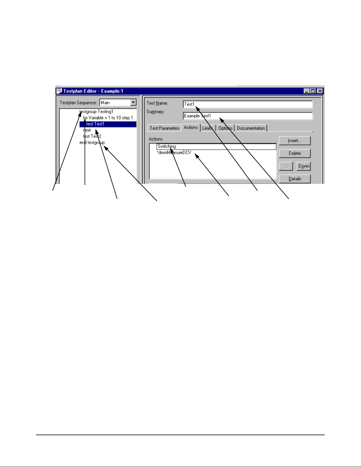
Figure 1-1 shows a testplan and some of its components; an explanation
follows the figure (see Loading a Testplan for an explanation on how to load
a testplan).
Figure 1-1. Typical Testplan Components
Testgroup A named block of tests that can be executed in a predefined order. Each
testgroup in a testplan must have a unique name; no duplicate names are
allowed.
List of Statements Test or flow control statements executed in the order shown.
Test A named series of actions that can be executed as a group. A test can contain
actions and switching actions. A test can have limit checking capabilities to
determine if a test passes or fails. A test must have a unique name; no
duplicate names are allowed.
Switching Action Actions that make connections from the instrument and loads to the Unit
Under Test. These actions are internal to Agilent TestExec SL. The
switching information in these actions are determined by the data in the
'system.ust' file and the user-generated fixture.ust and uut.ust files.
Action The smallest component in a test or testgroup that can be called to perform
functions such as setting up an instrument, making measurements and
prompting the user.
10 System Software Overview Chapter 1
Page 11

Actions
The system comes with a set of supplied actions. These actions are used for
such things as configuring instruments, making measurements and
prompting users for inputs. You can also generate custom actions using the
Action Wizard and an application program such as Visual C/C++.
The action directory path is:
C:\Program Files\Agilent\TS-5000 System
Software\actions
Actions are located in the following sub-directories:
Sub-Directory Action Type
arb Arbitrary Waveform Generator Actions
counter Counter Actions
dac D/A Converter Actions
dgn Diagnostics Actions
digitizer Digitizer Actions
dio Digital I/O Actions
dmm Digital Multimeter Actions
dso Digital Storage Oscilloscope
event Event Detector Actions
generic Miscellaneous Actions
mcm Measurement Control Module Actions
power Power Supply Actions
serial Serial Interface Actions
SerialProtocol Automotive Serial Protocol Actions
switch SLU and Switching Actions
vi Voltage / Current Source Actions
daq Data Acquisition Actions
esa Spectrum Analyzer Actions
esg Signal Generator Actions
System.ust File
The 'system.ust' file is created at the factory with the appropriate
module/instrument and wiring data according to the system option. The file
can be edited using the System Configuration Editor (see
System Software Overview 11Chapter 1
“System
Page 12
Configuration Editor” on page 14) or the Topology Editor in Agilent
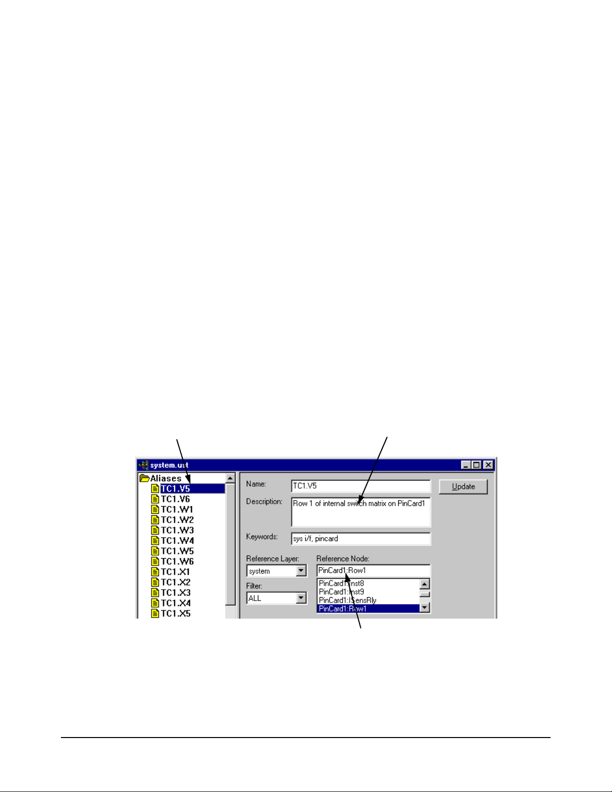
Alias Name
Alias Description
Reference Node
TestExec SL.
The data in the 'system.ust' file consists of modules/instruments and
instrument nodes (i.e., connections at the 32-Pin Matrix and Instrument
Multiplexer Module), and other nodes (connections at the 32-Pin Matrix
Modules and load cards) using the Aliases, Wires, and Modules
designations. The Module designations are used to determine the
modules/instruments installed in the system, and the Aliases and Wires are
used to generate switch paths.
A typical 'system.ust' file contains Aliases, Wires and Modules.
Aliases These are alternate names for reference nodes. The names are descriptive in
nature to easily identify the node. For example, the node name for the high
current output of the Agilent 34401 or E1411 Digital Multimeter is called
"IsrcHi".
Figure 1-2 shows typical Aliases in the 'system.ust' file.
Wires These are names for wires that connect to or between nodes. In some cases,
these names are the same aliases used for nodes. For example, the alias
called "DVMIsrcHi" is often used for the wire name that connects to that
Figure 1-3 shows typical wires in the 'system.ust' file.
node.
Modules These are the names of the instruments in the system. For example, the name
"MCM" indicates that there is an Agilent E6171B Measurement control
module in the system. The
'system.ust' file.
Figure 1-2. Typical Aliases
Figure 1-4 shows a few typical modules in the
12 System Software Overview Chapter 1
Page 13
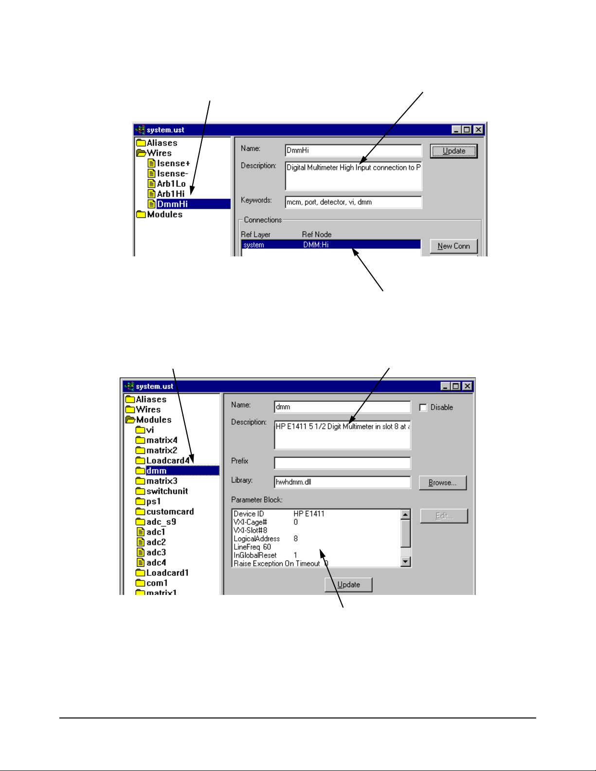
Figure 1-3. Typical Wires
Wire Name
Wire Description
Reference Node
Module Name
Module Description
Module Related Data
Figure 1-4. Typical Modules/Instruments
System Software Overview 13Chapter 1
Page 14

System Configuration Editor
This editor can be used to add new modules/instruments or delete old
modules/instruments to/from the system.ust file (see
page 11 for information). It can add/delete any supported GPIB or VXI
instruments, Pin Matrix Modules, and/or load cards.
The editor has the following functions:
• Shows all supported modules/instruments.
• Automatically detects all modules/instruments currently in the system
• Able to add new custom modules/instruments to the system.ust file
• Able to edit module/instrument parameters
Any of the supported and custom modules/instruments can be added to the
system.ust file. Dependent on the system type and option (e.g., Test System
Interface vs. Mass Interconnect), the System Configuration Editor
automatically generates the appropriate wires and aliases (see
File” on page 11 for information). The wiring, etc. data is located in a
spreadsheet that is specifically generated for your system type and option.
The System Configuration Editor is available from the TestExec SL Toolbar
or from a shortcut in the Desktop on the system PC controller. Refer to the
System Configuration Editor’s online help for more details.
“System.ust File” on
“System.ust
14 System Software Overview Chapter 1
Page 15

How to Use the System Software
Chapter Contents
Chapter 2
This chapter lists the needed software to run the system and shows some
system specific software operation. The chapter is separated as follows:
• Required Computer Hardware and Software . . . . . . . . . . . . page 15
• System Software Description . . . . . . . . . . . . . . . . . . . . . . . . page 16
• Selecting Agilent TestExec SL . . . . . . . . . . . . . . . . . . . . . . . page 17
• Loading a Testplan . . . . . . . . . . . . . . . . . . . . . . . . . . . . . . . . page 17
• Creating a Testplan . . . . . . . . . . . . . . . . . . . . . . . . . . . . . . . . page 18
• Using TS-5000 Supplied Actions . . . . . . . . . . . . . . . . . . . . . page 19
• Using Software Debug Features . . . . . . . . . . . . . . . . . . . . . . page 23
• Instrument Handlers . . . . . . . . . . . . . . . . . . . . . . . . . . . . . . . page 48
• Using the Action Wizard To Develop. . . . . . . . . . . . . . . . . . page 49
• Multithreading. . . . . . . . . . . . . . . . . . . . . . . . . . . . . . . . . . . . page 50
Required Computer Hardware and Software
The following is a list of the computer hardware and software needed to run
the Agilent TS-5000 Test System. All necessary software was factory
installed on your system:
• IBM-compatible PC (at least a Pentium) with 256 MB of RAM,
1024x768 graphics, 100 MB of free disk space (20 MB for Agilent
TestExec SL software).
• Microsoft
• Agilent TestExec SL software, Version 5.1 or later.
• Agilent TS-5000 Software version 5.1 or later.
Note For more detailed information about using the Agilent TestExec SL
software, refer to the software documentation
®
Windows® XP or 7 Microsoft® Windows® 64-Bit
How to Use the System Software 15Chapter 2
Page 16

System Software Description
The Agilent TS-5000 System uses Agilent TestExec SL and system specific
software to test the Unit Under Test. Agilent TestExec SL is a test executive
designed for high-volume, high-throughput functional test applications. The
other system specific software provides the communications between the
test executive and system instruments.
Agilent TestExec SL uses testplans and actions to perform the tests. The
actions are the building blocks from which the tests are created. The actions
are called from a test which are executed in a testplan. The switching actions
makes the connections from the system instruments, and/or loads on the load
cards to the Unit Under Test. The switching actions are built into Agilent
TestExec SL.
Both actions and switching actions are used in a testplan to run the tests. The
testplan automatically closes the appropriate pin matrix and load card
switches to make the connections, setup and execute the appropriate sources
and detectors, and return any test results.
The switching information and the instrument types used in the system are
located in the
custom for each system. It has the necessary information for the switching
actions to close the appropriate switches and for the other actions to
communicate with the system instruments. Instrument data in the
system.ust file can be generated and/or modified using the System
Configuration Editor (see
“TS-5000 System Integrator’s Manual”
system.ust file. This file is generated at the factory and is
“Using the System Configuration Editor” in the
).
16 How to Use the System Software Chapter 2
Page 17
Selecting Agilent TestExec SL
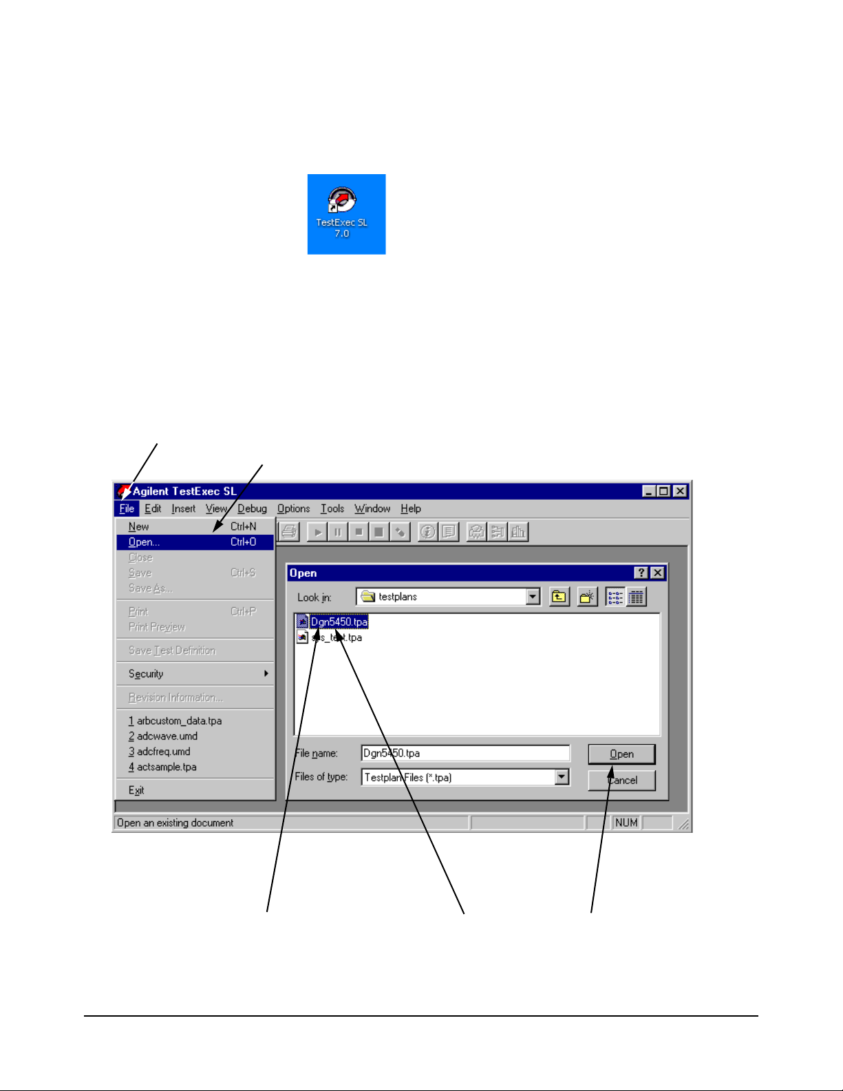
3. Double Click on File Name or Select File Name and click on “Open”
1. Select “File” menu
2. Select “Open” Menu Item or press “Ctrl+O” buttons
The Agilent TestExec SL software is pre-installed on your PC controller’s
hard drive. Start TestExec SL from this icon in the PC desktop:
You can also run TestExec SL by clicking:
Start | Programs | Agilent TestExec SL 7.0 | TestExec SL 7.0
Loading a Testplan
Figure 2-1. Agilent TestExec SL Main Screen and File Open Box
How to Use the System Software 17Chapter 2
Page 18
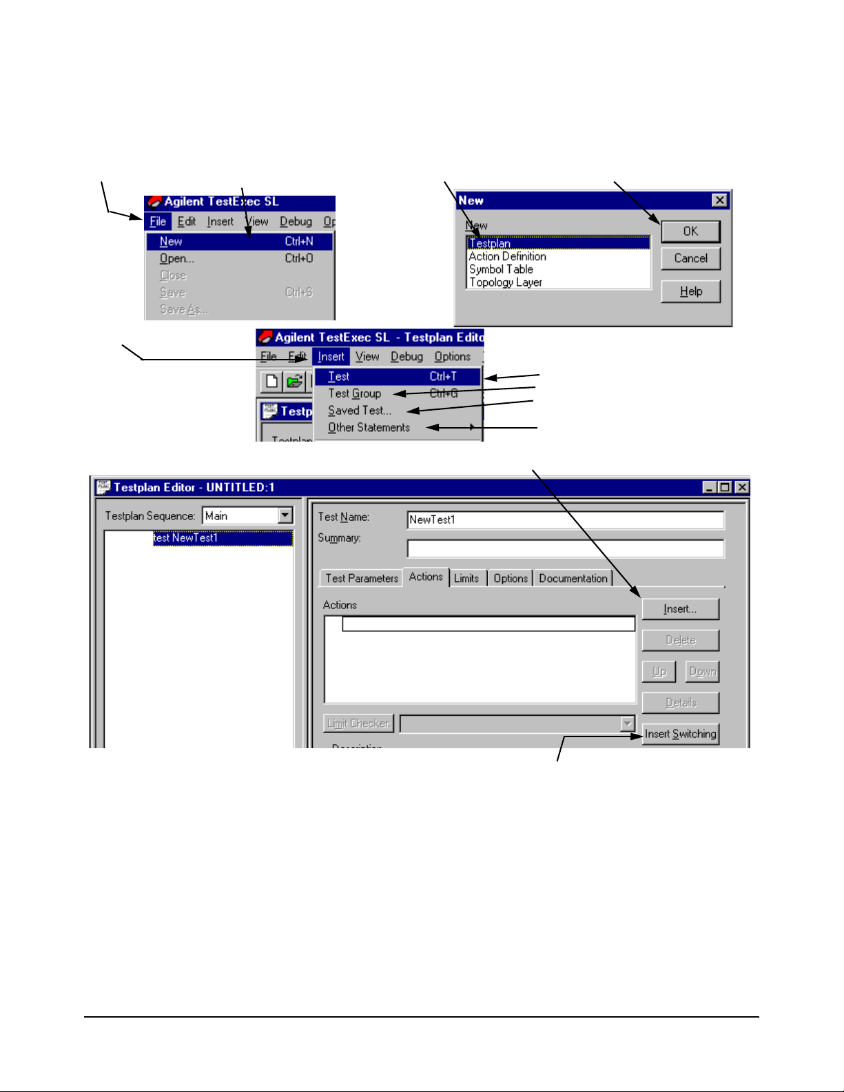
Creating a Testplan
1. Click on “File” menu
2. Click on “New” menu item
3. Click on “Testplan” 4. Click on “OK”
5. Click on “Insert” menu
6. Click on one of the following:
Test - inserts a new test
Test Group - inserts a new testgroup
Saved Test - inserts a test from a
previously saved test library
Other Statements - inserts a program
statement
7A. Click to insert action
7B. Click to insert switching action
Figure 2-2 shows how to create a testplan.
Figure 2-2. Creating a Testplan
18 How to Use the System Software Chapter 2
Page 19

Using TS-5000 Supplied Actions
The Agilent TS-5000 System with a set of standard actions supplied with the
system. The action directory path is:
C:\Program Files\Agilent\TS-5000 System Software\actions
Actions are located in the following sub-directories:
Sub-Directory Action Type
arb Arbitrary Waveform Generator Actions
counter Counter Actions
dac D/A Converter Actions
dgn Diagnostics Actions
digitizer Digitizer Actions
dio Digital I/O Actions
dmm Digital Multimeter Actions
dso Digital Storage Oscilloscope Actions
event Event Detector Actions
generic Miscellaneous Actions
mcm Measurement Control Module Actions
power Power Supply Actions
serial Serial Interface Actions
SerialProtocol Automotive Serial Protocol Actions
switch SLU and Switching Actions
vi Voltage / Current Source Actions
daq Data Acquisition Actions
esa Spectrum Analyzer Actions
esg Signal Generator Actions
Note The actions are summarized in Chapter 4 of this manual. The actions are
documented in detail in the TS-5000 online help which is available from
the TestExec SL Help menu.
How to Use the System Software 19Chapter 2
Page 20

Standard Action
Types
The standard actions are generally organized around a specific instrument or
module in the system. The actions are also separated into the types discussed
below.
High-Level Actions These are actions that usually perform complete tests, such as setting up a
source and then making a measurement. These actions normally, but not
always, use one or more of the Low-Level Actions.
Low-Level Actions These actions perform specific configuration or measurement function on a
particular instrument. The low-level actions give you more flexibility in
configuring instruments and making the measurements than do the
high-level actions. Low-Level actions are organized by instrument type and
function. For example, an action that is to set up triggering for a voltmeter
is a low-level action.
Example Testplans Example testplans to show how to use the actions are in the following
directory:
C:\Program Files\Agilent\TS-5000 System
Software\testplan\examples
Adding an Action to
a Testplan
Do the following:
1. Open Agilent TestExec SL using the procedure in “Selecting Agilent TestExe c SL” on page 17.
2. Either create a new or open an old testplan, using the procedure in “Loading a Testplan” on page 17 or “Creating a Testplan” on page 18, respectively.
3. If using a new testplan, do the procedure in Figure 2-2 on page 18 to add a test. If using an old testplan, select the test into which you wish to add an action and continue with step 4.
4. Add an action to the test, as shown in Figure 2-3 and Figure 2-4.
There are two different actions that can be added, a regular action and
a switching action.
Figure 2-4 shows how to add a switching action.
Figure 2-3 shows how to add a regular action and
20 How to Use the System Software Chapter 2
Page 21
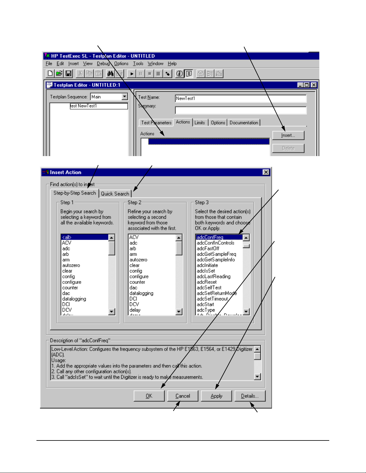
1. Select the place to add the action
2. Click on “Insert”
3. Either click on “Step-by-Step Search” or “Quick Search” (“Quick Search” shows all actions in a column)
4. Select the action
5. Click on “OK” to
Or
click on “Apply” to
Click on “Cancel” to close Click on “Detail” to open
add the action and
close the window
add the action, but
keep window open
to add more actions
window without adding action Action Definition Editor
Figure 2-3. Adding an Action
How to Use the System Software 21Chapter 2
Page 22
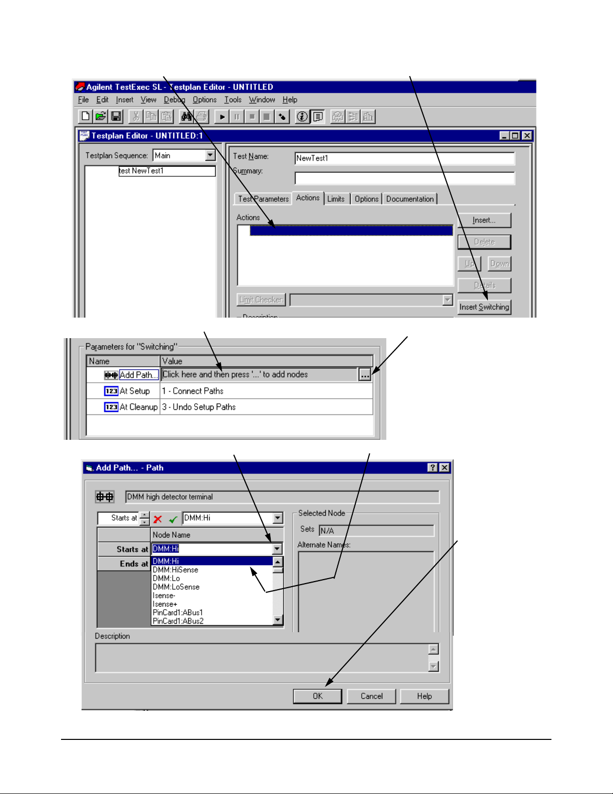
6. Select the place to add the switching action
8. Click on the “Value” field to view button with the three dots (. . .)
7. Click on “Insert Switching”
9. Click on the three dots
10. Click on arrow to view “Node Names”, then click on name to select it
11. Click on “OK” to
12. Repeat steps
select the node; use
the same procedure
for the “Ends At”
nodes
8 to 11 to add
other nodes
Figure 2-4. Adding a Switching Action
22 How to Use the System Software Chapter 2
Page 23
Using Software Debug Features
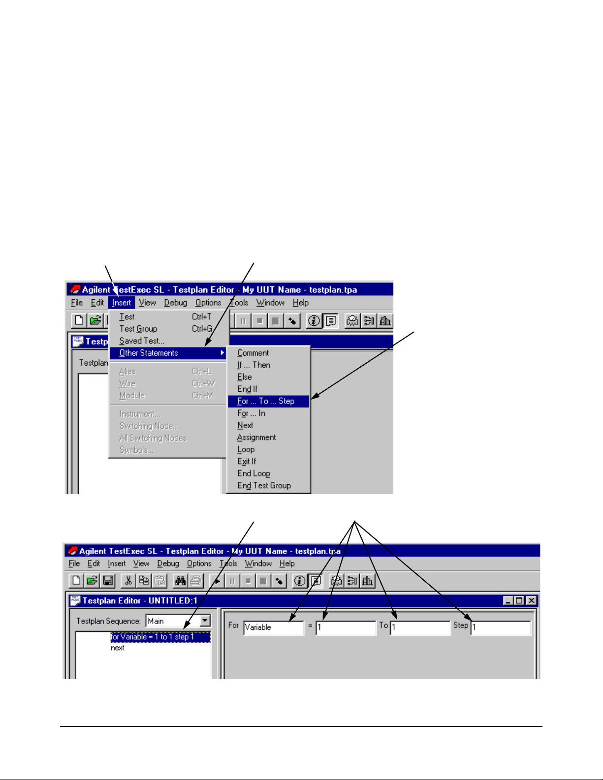
1. Click on “Insert” Menu
2. Click on “Other Statements” menu item
3. Click on looping
or other statement
4. Statement has been added; make any necessary changes
This section describes specific software features, unique to the Agilent
TestExec
debugging your tests and testplans. To enable Agilent TestExec
procedure in
Looping The loop constructs are FOR / NEXT sequencer statements. For example, a
testplan developer would stop a testplan (if one is running), add
NEXT lines to the testplan and then restart the testplan from the beginning.
Refer to the Agilent TestExec SL documentation for additional information.
Figure 2-5 shows how to select and insert the looping statements into a
testplan.
SL version 2.0 and later, that you will find helpful in creating and
“Selecting Agilent TestExec SL” on page 17, if not enabled.
SL, use the
FOR and
Figure 2-5. Selecting Looping and Other Statements
How to Use the System Software 23Chapter 2
Page 24
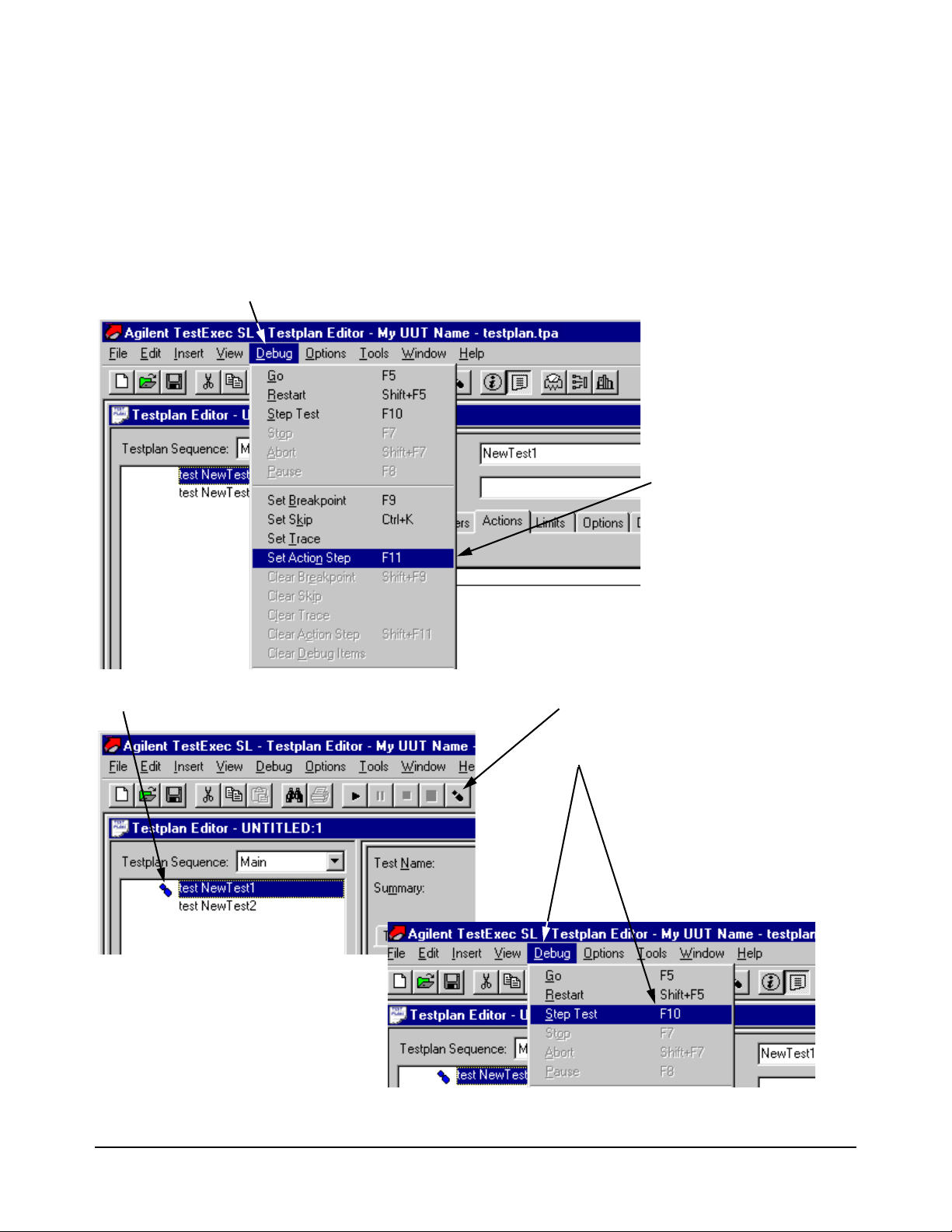
Single Stepping Agilent TestExec SL adds the ability to single step the execution of the
1. Click on “Debug” menu.
2. Click on “Set Action Step”
menu item
3. Foot symbol indicates that this step is to be paused
4. Click here to advance the test
Or
Click on “Debug” and “Step Test” to
advance the test
operations that make up a test. When stepping through the actions of a test,
the system pauses at entry point calls for each action routine. Action
stepping can be performed any time testplan execution is paused (as a result
of operator pause or test breakpoint). The action step which is currently
paused is listed in the trace window. Refer to the Agilent TestExec SL
documentation for additional information.
Figure 2-6 shows how to select the single stepping
Figure 2-6. Selecting Action Stepping
24 How to Use the System Software Chapter 2
Page 25
Action Debug
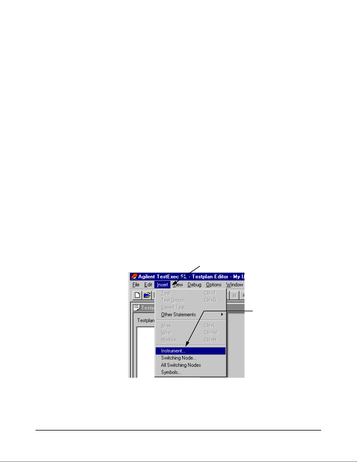
1. Click on “Insert” Menu.
2. Click on “Instrument”
menu item (or a
different item, if so
desired)
Messages
Agilent TestExec SL allows action routines to send strings to the same
debug window that the system uses for the test trace output. Use the
following API:
• UtaTrace (MessageString, MessageID)
-- MessageString is a string that will be sent to the trace window.
-- MessageID is an optional string that allows the messages to be
group (as identified by MessageID). Note: currently, this parameter
does not provide any functionality.
Watch Window Watch windows provide the ability to select ‘objects’ to dynamically
monitor as a testplan executes. Select an item to watch from a list, the item
is added to the watch window list and is updated each time the testplan
pauses. Items can be added or deleted at any time (as long as the testplan is
not running).
The watch window can monitor 4 types of objects:
• Instruments
• Switching Node
• All Switching Nodes
• Symbols
Watch Window Menu
Selections
The following shows some typical example of the window.
Watch Window Menu Selections shows how to select one of the four Watch
Window objects. The object to be selected, as shown in the figure, is the
‘instrument’ object. (The selection of the other objects is the same.)
Figure 2-7. Watch Window Menu Selections
How to Use the System Software 25Chapter 2
Page 26
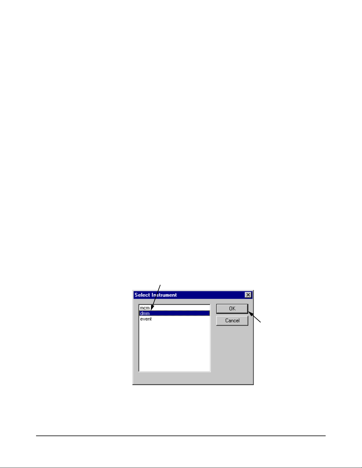
Watch Window
1. Click on the “dmm”, or a different, instrument to be watched
2. Click “OK” to enable
the Watch Window
Instrument Status
Watch windows are available for many of the instruments in an Agilent
TS-5000 system. The instruments that can be monitored are:
• Agilent E1328A or E1418A Digital to Analog Converter Module
(DAC)
• Agilent E1333A Counter Module
• Agilent E1411 Digit Multimeter Module (DMM)
• VXI Technology E1563A Analog to Digital Converter Module (ADC)
• Agilent E6171B Measurement Control Module (MCM)
• Agilent E6174A 32-Channel Event Detector Module
• Agilent 6642A, 6643A, 6652A, 6653A, 6673A Power Supplies
The displayed instrument states match the parameters of the instrument
handler routines. For example the Agilent E1411 Digital Multimeter has the
following routines which affect the state of the module:
• dmmConfFunction (dmm, Func, Range, Aperture);
• dmmConfCal (dmm, Linefreq, Autozero);
• dmmConfTrigIn (dmm, Trigselect, Trigcount, Delay);
• dmmConfSample (dmm, Sampsrc, Count, Period);
Figure 2-8 shows the menu box to select the instrument to be watched. The
figure shows how to select the Digital Multimeter (dmm).
To add an instrument to the Watch Window, select the instrument type and
press “OK”, as shown in
as shown in Figure 2-9.
Figure 2-9 also shows the expanded tree view that shows the status of the
‘dmm’ parameters. The instruments display their state in a tree view. This
allows a logical grouping of states and reduces the amount of data displayed
by placing less important states in lower levels of the tree.
Figure 2-8. The Watch Window is then displayed,
Figure 2-8. Selecting an Instrument to be Watched
26 How to Use the System Software Chapter 2
Page 27
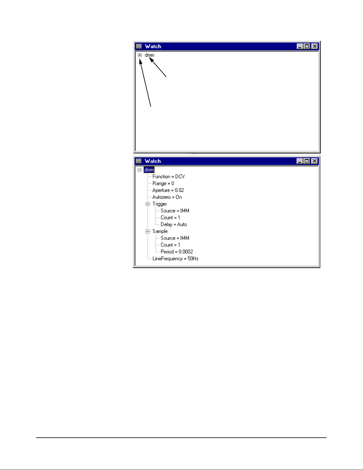
Shows that the “dmm” is watched
Click here to see the expanded view of the parameters (see below)
This is an expanded view of the dmm
(Agilent E1411 Digital Multimeter)
parameters
Figure 2-9. Agilent E1411B Digital Multimeter Watch Window with
Parameters
How to Use the System Software 27Chapter 2
Page 28

Instrument Debug
Front Panels
Agilent TestExec SL provides a series of debug instrument front panels for
the Agilent TS-5000 system instruments. The debug panels provide two
main features:
• The ability to interactively view the current Unit Under test (UUT)
state
• The ability to interactively view the current state of points within the
system.
Debug Panel Types The following debug panels are supplied with the system, dependent on the
modules/instrument currently installed in the system.
• Agilent E1411B Digital Multimeter . . . . . . . . . . . . . . . . . . . page 30
• Agilent E1328A & E1418A Digital to Analog Converter . . page 32
• Agilent E1333A Counter . . . . . . . . . . . . . . . . . . . . . . . . . . . page 33
• VXI Technology E1563A Digitizer . . . . . . . . . . . . . . . . . . . page 35
• Agilent E6171B Measurement Control Module . . . . . . . . . . page 36
• Agilent E6174A Event Detector . . . . . . . . . . . . . . . . . . . . . . page 37
• Agilent E6198A Switch/Load Unit. . . . . . . . . . . . . . . . . . . . page 38
• Agilent 6642A, 6643A, 6652A, 6653A, 6673A Power Supplies
page 39
Debug Panel Features All of the debug panels provide the following features:
• Changes on the instrument front panel are not made until either:
-- you initiate a measurement (for detectors) or
-- you press the “Apply” button (for sources)
The instrument state memory is modified in the instrument handler at
this time (since this is when the instrument handler is called;
Instrument Handlers on page 48 for information about handlers).
See
• If the instrument is connected in the Agilent TS-5000 system through
switching, the front panel provides a section which allows you to
define the switching path. Either select a UUT pin to connect to
directly or define a custom switch path.
Connecting to the UUT pin is the easiest way to select a switch path;
you select an ABus pin and the UUT pin. If the instrument has both the
high and low terminals connected to the switch matrix, then both pins
need to be defined. The low terminal is connected to UUTCommon by
default and does not need to be selected, if you use the default. The
UUT option is available if you have defined a UUT switching
configuration file. In addition to the UUT pins, the system
automatically adds the option to measure an ABus pin only. This will
allows you to inject a signal on the front of the system and measure it
using the instrumentation within the system.
• The state of the system is saved upon entering a pause state and is
restored when entering the run state. This allows the panels to be used
28 How to Use the System Software Chapter 2
Page 29

without affecting the testplan.
1. Click on “View” menu
2. Click “Instrument”
menu item
1. Select the Instrument of which the Debug Panel is to be displayed
2. Click “OK” to enable
the Debug Panel
Selecting the Debug
Panel
Debug Front Panel Selection and Select an Instrument from the Debug Front
Panel Selection show how to enable the debug instrument front panels.
Figure 2-10. Debug Front Panel Selection
Figure 2-11. Select an Instrument from the Debug Front Panel Selection
The following sections show and explain the different debug instrument
panels.
How to Use the System Software 29Chapter 2
Page 30
Agilent E1411B Digital
A
B
B
Multimeter
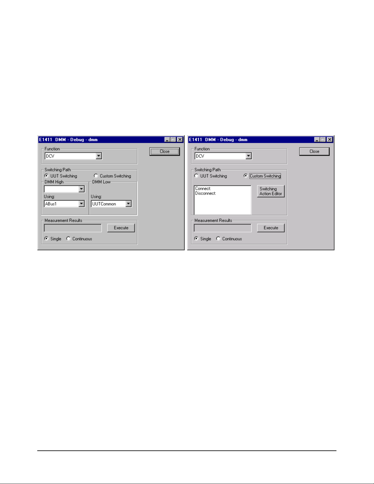
An instrument box which connects to the Agilent E6171 Measurement
Control Module, such as the Agilent E1411 DMM, usually has two different
dialog boxes which depend on the type of path selected (as shown in
Agilent
E1411 DMM Debug Front Panel (showing Path Selection)A and Agilent
E1411 DMM Debug Front Panel (showing Path Selection)B). This allows
you to either connect to the pin on the UUT (Agilent E1411 DMM Debug
Front Panel (showing Path Selection)A) or select any point within the
system by defining a custom switching path (Agilent E1411 DMM Debug
Front Panel (showing Path Selection)B). The custom switching is applied on
top of the current switching state, so to undo a switching path you need to
define a ‘disconnect’ path.
Figure 2-12. Agilent E1411 DMM Debug Front Panel (showing Path Selection)
The debug panel boxes and buttons do the following:
Function:
Choose ACV, DCV, Ohms, Ohms - Offset Compensated
The measurement is made in auto range and medium resolution.
Switching Path:
The debug panel supports the selection of the switching path. The
panel switches both high and low connections of voltage sense and the
high and low connection of the current terminals. The sense
connections are connected in parallel with the high and low terminals.
You specify the high or low terminal and the system automatically
connects the associated sense terminal.
Measurement Results:
Press the “Single” button to initiate a single measurement; press the
“Continuous” button to initiate a series of measurements. The
continuous button is modified to a “Stop” button once pressed. When
the dialog box is brought up, the measurement results box is blank.
Switching Action Editor:
This button enables the editor to select the switching paths for the
30 How to Use the System Software Chapter 2
Page 31

Digital Multimeter. See “Fast Connection Selection” on page 40 for a
description on how to use the editor.
Execute:
This button starts a measurement.
Close:
This button closes the debug panel.
System Interface
The setting of the Digital Multimeter function uses the following actions:
dmmMeasureDCV, dmmMeasureACV, dmmMeasureOhms
The above actions also return the results of a measurement.
How to Use the System Software 31Chapter 2
Page 32

Agilent E1328A &
E1418A Digital to Analog
Converter
Agilent E1328A and E1418A DAC Debug Front Panel shows the dialog box
for controlling the Agilent E1328/E1418 Digital-to-Analog Converter
(DAC) Module.
Figure 2-13. Agilent E1328A and E1418A DAC Debug Front Panel
The debug panel boxes and buttons do the following:
Voltage or Current:
You have the option to specify the output voltage or current for each
channel of the DAC. The ‘Type’ selection sets the voltage or current
mode and defines contents of the input field.
Dependent on the type selected, enter the voltage value/current value
into the Voltage/Current field.
(Note the E1328A cannot programmatically select the voltage or
current option.)
Update Output:
This button changes the output setting.
Close:
This button closes the debug panel.
System Interface
The setting of the DAC uses the following action routine:
dac16i_setup
32 How to Use the System Software Chapter 2
Page 33

Agilent E1333A Counter Agilent E1333 Counter Debug Front Panel shows the dialog box for Agilent
E1333A Counter. Only the UUT connection screen is shown. The custom
path selection is the same used by the Digital Multimeter (see
on page 30).
Figure 2-12
Figure 2-14. Agilent E1333 Counter Debug Front Panel
The debug panel boxes and buttons do the following:
Function:
Choose Frequency, Period, Positive Pulse Width, Negative Pulse
Width, Totalize
Input, Coupling, Input Impedance:
Allows you to set input functions. The setting of each function is sent
before a measurement is made.
Switching Path:
The counter panel supports the selection of a switching path. The
counter switches only the high connections of the output. The low
connections are automatically connected to system ground.
How to Use the System Software 33Chapter 2
Page 34

Measurement Results:
Select the “Single” button to initiate a single measurement or the
“Continuous” button to initiate a series of measurements. The
continuous button is changed to a “Stop” button, once pressed.
Note that when the dialog box is brought up, the measurement results
box is blank.
Execute:
This button starts a measurement.
Close:
This button closes the debug panel.
System Interface
The setting of the counter function will use the following action routines:
ctrMeasureFrequency, ctrMeasurePeriod, ctrMeasurePulseWidth,
ctrMeasureTimeInterval, ctrMeasureTotalize
The measurement uses the level trigger specified in the dialog box (using the
slider control), a default range and default resolution.
The input section uses the following action routine:
ctrMeasureInControls
34 How to Use the System Software Chapter 2
Page 35

VXI Technology E1563A
Digitizer
Figure 2-15 shows the debug front panel for the VXI Technology E1563A
Digitizer. Only the UUT connection screen is shown. The custom path
selection is the same as for the Agilent E1411B Digital Multimeter (see
“Agilent E1411B Digital Multimeter” on page 30).
Figure 2-15. VXI Technology E1563A Digitizer Debug Front Panel
The debug panel boxes and buttons do the following:
Time Base and Range:
The range and timebase can be modified by selecting the “arrow” keys
on the side and bottom of the waveform. To update the display, take a
new measurement.
The time base allows the following range of selections:
50 nS to 20 Sec in 1, 2, 5 steps
the range has the following selections:
0.1 to 100 volts in 1, 2, 5 steps.
When the dialog box is brought up, the combo box contains the current
time base and range. All of the setting for the digitizer are saved until
an actual sweep is initiated.
Input and Triggering:
These two sections allow you to set a variety of input and trigger
functions. The setting of each function is sent when a measurement is
made.
Switching Path:
The debug panel supports the selection of a switching path. The
digitizer switches both the high and low connections of the output.
How to Use the System Software 35Chapter 2
Page 36

Waveform Display:
Select the “Single” button to generates a single waveform display or
the “Continuous” button to generate a continuous update of
waveforms. The display updates at a rate of >10
Close:
This button closes the debug panel.
System Interface
The setting of the digitizer function will use the following action
routines:adcConfArm, dcConfFreq, adcConfInControls, adcIsSet,
adcGetResults
update/sec.
Agilent E6171B
Measurement Control
Module
Figure 2-16. Agilent E6171B Measurement Control Module Debug Front Panel
Agilent E6171B Measurement Control Module Debug Front Panel shows
the dialog box for controlling the Agilent E6171B Measurement Control
Module.
The debug panel boxes and buttons do the following:
Voltage or Current:
You have the option to specify the output voltage or current for each
channel of the MCM. The ‘Type’ selection sets the voltage or current
mode.
Dependent on the type selected, enter the voltage value or current
value into the Voltage or Current field, respectively.
Expected Current (when enabled by the Type-Current):
Defines the expected current of the MCM (or VI, i.e., Voltage/Current)
source.
Update Output:
This button changes the output source of the MCM.
Close:
This button closes the debug panel.
System Interface
The setting of the counter function will use the following action routines:
viSetSourceDCI, viSetSourceDCV, viSet
36 How to Use the System Software Chapter 2
Page 37

Agilent E6174A Event
Detector
Agilent E6174A Event Detector Debug Front Panel shows the dialog box for
controlling the Event Detector Module.
Figure 2-17. Agilent E6174A Event Detector Debug Front Panel
The debug panel boxes and buttons do the following:
Clock Frequency:
Select the clock rate of the event detector module.
Edge Trigger, External Gating and Number of Events:
Specifies the type of edge triggering to be used and external gating.
The text box defines the number of events to be logged before a
measurement is complete.
Event Display:
The event detector can generate either a single display or a continuous
update of events. The table provides a simple list view of the event and
it’s time stamp. The column width can be adjust by dragging the line
which separates the titles.
Execute:
This button starts a measurement.
Close:
This button closes the debug panel.
System Interface
The setting of the event detector will use the following action routines:
eventMeasure
How to Use the System Software 37Chapter 2
Page 38

Agilent E6198A
Switch/Load Unit
Agilent E6198A Switch/Load Unit Debug Front Panel shows the dialog box
for controlling the Switch/Load Unit.
Figure 2-18. Agilent E6198A Switch/Load Unit Debug Front Panel
The debug panel boxes and buttons do the following:
Digital I/O Read:
Reads a value from the Agilent E6198 switch/load unit digital input
ports. Fixture ID is value from Fix_ID(0..7) of access connector J104
and Spare is value from Spare_DigIn(0..7) of access connector J104.
Digital I/O Write:
Write a value to the Agilent E6198 switch/load unit digital output
ports. Open Collector writes to output port on the switch/load unit
backplane. Spare writes to output Spare_DigOut(0..7) on backplane
connector J104.
Digital to Analog Converter DAC #1/DAC #2:
Change the voltage, gain, and offset values used to set the DAC
voltage in the switch/load unit for both DAC #1 and DAC #2.
System Interface
The setting of the switch/load unit will use the following action routines:
digitalWriteSU, digitalReadSU, dacSetDCVSU, dacSetGainOffsetSU
38 How to Use the System Software Chapter 2
Page 39

Agilent 6642A, 6643A,
6652A, 6653A, 6673A
Power Supplies
Power Supply Debug Front Panel shows the dialog box for controlling the
Agilent 6642A, 6643A, 6653A, 6673A Power Supplies. You can specify the
output voltage or current for each channel of the Power Supply. You must
specify a protection voltage greater than the voltage setting.
Figure 2-19. Power Supply Debug Front Panel
The debug panel boxes and buttons do the following:
Voltage/Current:
Specifies the output voltage or current for each channel of the power
supplies. The ‘Type’ selection sets the voltage or current mode.
Dependent on the type selected, enter the voltage value or current
value into the Voltage or Current field, respectively.
Update Output:
This button changes the power supply output.
Close:
This button closes the debug panel.
System Interface
The setting of the counter function uses the following action routines:
psConfVI, psSet, psIsSet, psConnect, psDisconnect
How to Use the System Software 39Chapter 2
Page 40

Fast Connection
Selection
You can select a switching path to a module/instrument either by selecting
pins on the Unit Under Test (UUT) (see “Switching Path” box in
E1411 DMM Debug Front Panel (showing Path Selection)A on page 30) or
by creating a custom path using the Switching Action Editor (see “Switching
Action Editor” button in
Path Selection)B on page 30).
Agilent E1411 DMM Debug Front Panel (showing
Agilent
Specifying Unit Under
Test Pin s
Creating a User Defined
Switching Path
When selecting UUT pins, you normally specify from 1 to 4 connections,
depending on the module/instrument. For example, for the Digital
Multimeter (DMM), you define these four connections: high, low, high
current sense, and low current sense. The Counter only has only a high
connection.
The software works backwards though the switching configuration and
generates a switching path which connects to ABusx, depending on the
option selected. For example, a typical connection from ABus1 to the high
input of the Digital Multimeter would be: [DVMHi ABus1 VISrcHi]
User defined switching paths are created using the “Select Switching Path”
screen which is enabled by the “Switching Action Editor” button (see
Agilent E1411 DMM Debug Front Panel (showing Path Selection)B on page
30). The “Select Switching Path” screen shows two different fields, the
‘Connect’ and ‘Disconnect’ fields. All paths added or listed in the ‘Connect’
field are always connected. All paths added or listed in the ‘Disconnect’
field are always disconnected. Note that the fields are blank, if no paths have
previously been added.
To add/edit/delete a path, first enable the “Select Switching Path” screen
using an appropriate instrument panel, as shown in
uses the Agilent E1411B Digital Multimeter instrument panel.
The following shows how to add/edit/delete a path.
Figure 2-20. The figure
40 How to Use the System Software Chapter 2
Page 41

Figure 2-20. Enabling the “Select Switching Path” Screen
1. Select “Custom Switching” radio button
2. Click on “Switching Action Editor”
to select the next “Select Switching
Path” window
Adding a New Path
To add a new path, first determine the end nodes or points in the path. Then
use the “Switching Action Editor” to find a path using the intermediate
nodes between the end notes or points.
For example, to connect the Hi input of the Agilent E1411B Digital
Multimeter (DMM) to the Hi output of the Agilent E6171 Measurement
Control Module (MCM), you must know the node names for these
connections. Also, since the DMM has no direct connections to the VI
source or MCM, it must connect using ABusx. Thus, the nodes for this path
would be: [DVMHi
ABus1 VISrcHi].
Before adding a new path, first use the procedure in Figure 2-20 to enable
the “Select Switching Path” screen. Then use the procedure in Figure 2-21
to add the path.
Editing a Switching Path
To edit a path, first use the procedure in Figure 2-20 to enable the “Select
Switching Path” screen, if the screen is not enabled. Then use the procedure
Figure 2-22 to edit the path.
in
Deleting a Path
To delete a path, first use the procedure in Figure 2-20 to enable the “Select
Switching Path” screen, if the screen is not enabled. Then use the procedure
Figure 2-23 to delete the path.
in
How to Use the System Software 41Chapter 2
Page 42

2. Choose a node name to be used in the path
3. Click “Select” to select the node; perform
4. Click on “OK” to add the node and close
5. Click on “OK” to return to the instrument
To add another path, click “Add Path” again,
This is the newly added path
1. Click to add a path to the “Connect” field
to enable the “Switching Path Editor”
Or
Click to add a path to the “Disconnect” field
to enable the “Switching Path Editor”
(e.g., “DVMHi”)
step B and this step to select all nodes used
in the path
the “Switching Path Editor”
before clicking on “OK”
panel
Figure 2-21. Adding a New Switching Path
42 How to Use the System Software Chapter 2
Page 43

1. Click on the Switch Path to be edited
2. Click the “Edit Path” button.
3. Select the Node to be changed by
4. Click on “OK” to make the changes and
5. Click one “OK” to return to the instrument
clicking on “Back Up” until the node to be
changed has been deleted; then click on
“Select” to add the new node and continue
adding the previously deleted nodes you
wish to keep
panel
close the “Switching Path Editor”
Figure 2-22. Editing a Switching Path
How to Use the System Software 43Chapter 2
Page 44

Figure 2-23. Deleting a Switching Path
1. Click on the Path to be deleted
2. Click on “Delete Path” to delete the path
3. Click on “OK” to return to the instrument
panel
44 How to Use the System Software Chapter 2
Page 45

Viewing Waveforms A ‘Waveform’ data type is available in the “ADC_Analyze_Wave”
Click on the parameter value to select it
then click on the dots (...) to enable the
waveform editor
High-Level Action. This data type includes a graphical viewer for data.
Sample Testplan Showing Waveform Data Type shows a sample testplan
using the “ADC_Analyze_Wave” Action with the Waveform parameter.
Range Data on the Waveform Display Graphical Editor and Sample
Waveform Display show the waveform editor, and Figure 2-27 shows the
waveform display.
Figure 2-24. Sample Testplan Showing Waveform Data Type
How to Use the System Software 45Chapter 2
Page 46

Figure 2-25. Range Data on the Waveform Display Graphical Editor
Set Start and Stop
Set the number of
time value for
waveform
points on the
waveform
Click to add range data
Click to add amplitude data
Add amplitude data here
Click to view waveform (see next figure)
46 How to Use the System Software Chapter 2
Figure 2-26. Amplitude Data on the Waveform Display Graphical Editor
Page 47

Figure 2-27. Sample Waveform Display
Click on “OK” to store waveform
How to Use the System Software 47Chapter 2
Page 48

Instrument Handlers
User Actions
Instrument Handler
Driver
Instrument Handlers are a layer of software between Agilent TestExec SL
and standard instrument drivers (see
Handlers are designed to be called from C/C++ code action.
Instrument handlers contain functions written in C code that are organized
by instrument type and function, and require parameters relevant to the
function. For example, the call to set up triggering for a voltmeter is:
Figure 2-28). In general, Instrument
Figure 2-28. Software Layers
Note Instrument handlers are maintained constant in different TS-5000 software
dmmConfTrigIn (dmm, trigselect, count, delay);
Function dmmConfTrigIn accepts four parameters: dmm, trigselect, count,
and delay. The generic name of the function is
of the instrument, in this case
specific name of the function.
releases, which is not the case with the drivers. Thus, use instrument
handlers for actions whenever possible.
dmm, is added as a prefix to form the full,
ConfTrigIn, and the name
48 How to Use the System Software Chapter 2
Page 49

Using the Action Wizard To Develop
1. Click on “Tools” menu
2. Click on “Action Wizard” menu item.
The Agilent TestExec SL application used in the TS-5000 System comes
with a program called Action Wizard to develop actions. The Action Wizard
automatically runs through the steps necessary to develop an action. The
wizard also includes a help file with more detailed instructions and
information on how to use the wizard.
To run the “Action Wizard”, use the procedure in Figure 2-29.
Note Actions are the smallest components of a test and are used to setup and
execute instruments, perform cleanup functions, and to make
measurements.
Figure 2-29. Selecting and Running the Action Wizard
How to Use the System Software 49Chapter 2
Page 50

Multithreading
Multithreading is an execution model which allows multiple threads to exist
within a single process. It contains more than one unit of execution in a
single process. In the context of TestExec SL, multithreading is the
capability of running more than one thread. These threads share the process's
resources but are able to execute independently.
A thread is a basic unit of execution. A single thread executes a series of
application instructions, following a single path of logic through the
application. All applications have at least one thread, but you can design
your applications to use multiple threads, with each thread executing
separate logic.
This capability becomes useful when a process thread stalls due to necessary
data that are not yet available or when switching to another thread will yield
a better result. In a single threaded program, once the main execution thread
is blocked the whole application comes to a standstill. However, with
multithreading, blocked programs can be moved from the main execution to
a separate thread and can be concurrently executed with the main execution.
This allows the application to stay responsive while executing tasks in the
background. Multithreading can lead to improved performance as many
threads are executed concurrently.
However, there are always disadvantages to complex application like this.
Executing a multithreaded test can be more difficult than a typical test as
there can be time related defects. In order for the operating system to track
a large number of threads, it is going to consume processor time. If there are
too many threads, then each thread may not be given enough time to execute
during its time slice. In addition, each thread is scheduled for execution less
frequently due to the volume and time slice committed to each thread.
How Multithreading
is working on a
Testplan?
50 How to Use the System Software Chapter 2
a. Creating a Thread Safe Action
Thread safe is a concept that can be applied in multithreading. A piece of
code is thread-safe, if it functions correctly during simultaneous execution
in multiple threads. By using thread-safe routines, the risk that one thread
will interfere and modify data elements of another thread is eliminated by
circumventing potential data race situations with coordinated access to
shared data.
For a thread to be thread-safe, it first must behave correctly in a
single-threaded environment. Furthermore, for a thread to be thread-safe, it
must continue to behave correctly when accessed from multiple threads,
regardless of the scheduling or interleaving of the execution threads by the
runtime environment and without any additional synchronization on the part
of the calling code. The effect is that operations on a thread-safe object will
appear in a fixed, globally consistent order to all threads.
The thread safe declaration is introduced as an indicator. By default, an
action is not thread safe and is indicated by a visual cue.
Page 51

Figure 2-30. Symbol of thread safe declaration
If you do not wish to see a visual cue next to non-thread safe action, click
Options | Testplan Options and in the Threading tab, uncheck the Mark
non-thread-safe action checkbox.
Note: If check “Force testplan to run in sequential mode” checkbox, all
testplans will run in sequential mode. For multithreading mode, the
checkbox must be unchecked.
Figure 2-31. Testplan Option for Mark non-thread-safe action
To create a thread safe action,
1. Double-click an action and the Action Definition Editor window will appear.
2. Enter "thread_safe" under Keywords.
3. Click Add.
You should now be able to see thread_safe in the right column. Take note of
the highlighted areas.
How to Use the System Software 51Chapter 2
Page 52

Figure 2-32. Action Defination Editor
4. The visual cue will disappear once the action has been declared as thread safe.
Figure 2-33. Disappear Thread Safe’s symbol
b. Settings for a Threaded Test
To thread a test, select the Threading tab and check the Thread This Test
checkbox. A threaded visual cue will appear next to the test once the test has
been threaded, as shown below.
52 How to Use the System Software Chapter 2
Page 53

Figure 2-34. Thread This Test
c. Using Resource Locking
Resource locking is the process of protecting data in a multiprocessing
environment. It means at the same point of time only one thread can access
to this method of created object. Unless the lock is released after completion
of the code, the next routine or iteration cannot enter the block. In the context
of TestExec SL, resources that can be locked are switching paths, instrument
handlers, action access, and reference parameters.
TestExec SL supports two types of resource locking which are full locking
and partial locking. By implementing multithreaded tests and choosing the
correct resource locking that fits your test, you can easily control the sharing
of instruments and synchronize multiple UUTs. In full locking mode,
TestExec SL will automatically perform locking on all objects underneath
the test objects which are switching paths, instrument handlers, action
access, and reference parameters. In partial locking mode, TestExec SL
allows you to manually apply one or more of the above mentioned locks to
the object(s).
Resource locking can be applied to each of the containing objects under the
test object. Tests can be manually locked by selecting the Threading tab.
Click the Lock All Test Objects checkbox for a full lock or click an
individual lock to choose your preferred lock. The visual cues for full
locking and partial locking slightly differ in color.
How to Use the System Software 53Chapter 2
Page 54

Figure 2-35. Lock All Test Objects
Figure 2-36. Lock Test Objects partially
d. Using the Wait Thread Statement
One way to think of the wait thread statement is to imagine an item of data
such as an integer variable as if it were a field in a database. If you do not
have some locking mechanism in the database you stand a chance of
corruption to the data.
Thus, one user might retrieve the data and perform a calculation and write
back the data. If in the meantime someone else has retrieved the data,
performed the calculation and written it back, the second user's calculations
will be lost when the first person writes back to the database. In the way that
a database has to handle updates at unpredictable times, so a multithreaded
program has to cater for this possibility. TestExec SL has a wait thread
statement especially to resolve matters like this.
54 How to Use the System Software Chapter 2
Page 55

The Wait Thread statement allows you to block remaining statements from
execution prior to completion of threaded tests statement in the Wait For
column.
To insert a Wait Thread statement, click Insert | Wait Thread in TestExec
SLs menu bar. The maximum timeout value is used to specify the maximum
duration a Wait Thread statement would need to wait for the threads. A
timeout of 0 ms means the program will wait forever until all the waited
threaded tests have completed execution.
The below testplan shows that NewWaitthread needs to wait for NewTest1
to complete execution.
Figure 2-37. Wait Thread statment
Using Wait Thread Statement in Loop, For...In and For...To...Step
Statements
It is recommended to insert Wait Thread statement right before Next
statement in Loop, For...In and For...To...Step statements if threaded tests
exists within these statements. The Wait Thread statement needs to wait for
all threaded tests within the Loop and For Loop statements, otherwise, the
results might be unexpected.
Using Wait Thread Statement for Throughput Multiplier Threaded
Test Statement
It is also recommended to insert Wait Thread statement after a throughput
multiplier threaded test statement to wait for all the threads running for all
the UUTs to complete execution before proceeding on with next statement.
How to Use the System Software 55Chapter 2
Page 56

Using Wait Thread Statement in Testgroup Statement
A Wait Thread statement should be inserted right before end testgroup
statement if threaded tests exist within the testgroup statement. The Wait
Thread statement needs to wait for all threaded tests within the testgroup,
otherwise, the results might be unexpected.
Using Wait Thread Statement in Sequence Library
A Wait Thread statement should be inserted as the last statement of a
sequence library (local or external) if threaded tests exist in the sequence
library. The Wait Thread statement is to ensure all the threaded tests in the
sequence library have completed their execution before returning to Main
sequence. If the Wait Thread statement is not inserted, threads in the
sequence library might be still running upon returning to Main sequence.
e. Using Timeout
A specified period of time that will be allowed to elapse in a system before
a the next specified event is to take place. TestExec SL allows you to specify
a timeout value as well as the behavior of the timeout. The timeout value is
set in the Wait Thread statement while it's behavior is set in Testplan
Options.
In Options | Testplan Options, a new Threading tab has been added to allow
users to specify the behavior of the timeout. There are three options you can
choose from:
• Generate exception
• Generate error message on report window and continue execute
• Prompt timeout dialog
Threaded objects are killed when timeout is exceeded. This timeout feature
is the simplest method of preventing of deadlocks.
Opening System Configuration Editor
1. Start System Configuration Editor from this icon on the PC desktop:
You can also run System Configuration Editor by clicking:
Start | All Programs | Agilent TS-5000 System Software 7.1.2
56 How to Use the System Software Chapter 2
Page 57

Adding an IVI-COM Module in System Configuration Editor
Note This feature will only be available for TS-5000 7.1 Service Pack 3 or
newer.
1. When System Configuration Editor opens, all devices that are
supported by current configuration will be shown by default.
To add a Standard IVI-COM module, double click its selection
available under the Device ID column as show below.
How to Use the System Software 57Chapter 2
Page 58

2. The window Configure Module will pop-up.
58 How to Use the System Software Chapter 2
Page 59

Adding a .Net Module in System Configuration Editor
1. When System Configuration Editor opens, all devices that are
supported by current configuration will be shown by default.
To add a Standard DotNet module, double click its selection available
under the Device ID column as show below.
How to Use the System Software 59Chapter 2
Page 60

2. The window Configure Module will pop-up.
60 How to Use the System Software Chapter 2
Page 61

Chapter Contents
Chapter 3
Using the DMM and ARB
This chapter describes how to trigger the DMM and how to use the ARB.
The chapter is separated as follows:
• Triggered Voltage Measurement . . . . . . . . . . . . . . . . . . . . . . page 62
• Using the Agilent E6173A Arbitrary Waveform Generator . page 65
Using the DMM and ARB 61Chapter 3
Page 62

Triggered Voltage Measurement
The Agilent E1411B Multimeter (DMM) can be triggered by a signal on the
VXI Mainframe’s backplane. This signal uses one of the TTL (i.e., TTL0 to
TTL7) trigger lines.
How to Trigger the
DMM
Testplan ‘dmmtrig.tpa’ shows how the DMM is triggered using the
Agilent E6174A Arbitrary Waveform Generator (Arb). The Arb is also used
to generate the signal measured by the DMM. The testplan also
demonstrates how to use the Agilent E6171B Measurement Control
Module’s (MCM) analog comparator. The testplan is in the following
directory:
C:\Program Files\Agilent\TS-5000 System
Software\testplan\examples
The Arb generates a ±5V 10 Hz square wave as the trigger signal. This
method uses the analog comparator of the MCM to send the trigger to the
DMM using the VXI Mainframe's backplane (see connections in
Figure 3-1
and Figure 3-2).
The testplan configures the MCM analog comparator to trigger at 0 volts.
Setting the “trigedge” parameter in the “viConfCompare” action to “0”
(positive edge detection), causes negative going backplane trigger when the
input signal makes a low to high (positive going) transition through the
trigger threshold. Setting the “trigedge” parameter in the “viConfCompare”
action set to “1” (negative edge detection), causes triggers when the input
signal makes a high to low (negative going) transition.
The following is a review of the testplan
Test/Action Name Description
test: Dmm Init Initializes the Digital Multimeter.
dmmConfCal Disables autozero and set the power line frequency.
dmmIsSet Waits for setup to complete.
test: Arb 1 pgm Configures Arb and outputs a 10 Hz +5V Square wave.
arbReset Reset the Arbitrary Waveform Generator (Arb) to its turn-on state.
arbConfOutControls Configures the Arb’s output circuitry.
Arb_Dl_Std_Waveform Download a 10 Hz square wave into the Arb.
arbInitiate Start outputting the waveform.
Arb_Select_Wave_By_Name Select waveform downloaded above.
test: VI Config0 (+5) Configures MCM’s analog comparator to trigger at 0V and a low to high (positive
transition) trigger.
viConfCompare Configures the comparator. The “trigedge” parameter value (0) causes a
backplane trigger when the input signal makes a low to high (positive going)
transition trough trigger threshold.
viIsSet Waits for setup to complete.
Test: Meas V - Trigger Trigger DMM and measure trigger voltage.
62 Using the DMM and ARB Chapter 3
Page 63

Test/Action Name Description
Switching Make the necessary switching to setup the Arb to DMM measurements and
dmmMeasureTrigVoltage Configures DMM for a measurement using the backplane TTL trigger line 0.
dmmGetResults Make the measurement and return the reading.
test: VI Config1 (-5) Configures MCM’s analog comparator to trigger at 0V and a high to low (negative
viConfCompare Configures the comparator. The “trigedge” parameter value (0) causes a negative
viIsSet Waits for setup to complete.
test Meas V - Expanded Trigger DMM and measure trigger voltage.
Switching Make the necessary switching to setup the Arb to DMM measurements and
DelayMillisecond Wait for switching to complete.
dmmInitiate Initiates a reading cycle.
dmmGetResults Make the measurement and return the reading.
trigger signal paths.
transition) trigger.
going backplane trigger when the input signal makes a high to low (negative
going) transition trough trigger threshold.
trigger signal paths.
Figure 3-1. Trigger Connections
Using the DMM and ARB 63Chapter 3
Page 64

Figure 3-2. Switch Paths Listing
64 Using the DMM and ARB Chapter 3
Page 65

Using the Agilent E6173A Arbitrary Waveform Generator
The following describes the Agilent E6173A Arbitrary Waveform generator
and how to use it.
Arbitrary Waveform
Generator
Description
How the Arb
Generates
Waveforms
The Agilent E6173A Arbitrary Waveform Generator (Arb), formerly the
Agilent Z2471A, is a register-based, two channel signal generator whose
channels are isolated from each other and from ground. The factory default
configuration connects first channel to the Agilent E6171 Measurement
Control Module (MCM).
You can amplify channel one's output using the MCM's V/I
amplifier/current source. You can connect channel two directly to your Unit
Under Test (UUT) or use one of the unassigned MCM inputs. The Arb can
also switch to any UUT pin by switching to Aux ports, if using the default
system pins.
The Arb can output standard waveforms, such as sine, square, triangle,
knock, or crank of a specified frequency, amplitude, and offset, and custom
arbitrary waveforms defined by the user.
The Arb generates waveforms using pre-defined or user defined segment
and sequence data.
The segments of a waveform are the voltage levels of each point on the
waveform. The sequence consists of a group of pre-defined or user defined
number of segments. To generate a waveform, the Arb outputs the sequence,
consisting of the defined number of segments, using a pre-defined time.
Figure 3-3 shows a typical example of a waveform.
The number of segments output (i.e., how often they occur) and the time of
the Arb’s internal clock (i.e., segment duration time) determines the time or
frequency of the waveform to be output. The Arb’s internal clock time is
µS. Either single or multiple clock cycles can be used to set the appropriate
2
frequency. Selecting the clock cycles is usually known as selecting the
“dwell” count.
For example, a waveform consisting of 250 segments using two 2 uS clock
cycles (or 2 dwell counts), outputs a 1 kHz waveform, shown as follows:
250 * (0.000002 * 2) = 250 * 0.000004 = 0.001 S = 1 kHz
In addition to the 2 µS clock, the Arb also has a 100 nS counter that can be
used to add time in 100 nS steps to the 2 µS clock cycles. This is used to
generate frequency accurate waveforms.The counter is normally set using
the “clock adjust” function. Note: Segment time = (Dwell + 1) * (2 µS +
(clock adjust * 0.1 µS)).
Both the segment data and sequence data is downloaded into the Arb’s
memory using the standard actions supplied with the system. These actions
can be used to download both standard (pre-defined) waveforms and user
defined waveforms.
Using the DMM and ARB 65Chapter 3
Page 66

Note For more information about the waveform timing, refer to the
Segment
Sequence
Segments
(voltage
values)
Duration
Agilent E6173A Arbitrary Waveform Generator User’s Manual.
Figure 3-3. Typical Waveform using Segments and Sequence
Generating Arb
Waveforms
Note DO NOT use the “Arb_Dl_xxx” actions with the older “ArbSetSegment”
Note When selecting different downloaded waveforms, usually when there are
There are several methods to generate Arb waveforms using the standard
actions. You can generate standard waveforms, such as sine, pulse, and
triangle waveforms, or you can create custom waveforms.
Many actions have been developed for high throughput operations. These
actions are generally named “Arb_Dl_xxx” where the “Dl” indicates the
actions with the high throughput capability (see
“In all testplans, the Arb
connects to the Analog Bus ABus1. To view the output, connect an
oscilloscope to the ABus 1 connector at the front of the system. Be sure to
make the necessary connection to the Mass Interconnect/Express Connect so
the interlock is shorted in order to use the system (see the appropriate
documentation). Instead of an oscilloscope, you can also use an VXI
Technology E1563A Digitizer to read the waveforms and display them
using the appropriate actions.” below).
and/or “ArbSetSequence” actions on the same Arb channel.
66 Using the DMM and ARB Chapter 3
Page 67

major frequency differences, the first few cycles of a newly selected
waveform may appear to be distorted. The reason is that the previous
waveform must complete, but the new “clock adjust” is already in effect,
which may change the timing of the last cycles of the previous waveform.
The following explains the methods used. For each method, there is a
testplan available it. The testplans are located in the following directory:
C:\Program Files\Agilent\TS-5000 System
Software\testplan\examples
In all testplans, the Arb connects to the Analog Bus ABus1. To view the
output, connect an oscilloscope to the ABus 1 connector at the front of the
system. Be sure to make the necessary connection to the Mass
Interconnect/Express Connect so the interlock is shorted in order to use the
system (see the appropriate documentation). Instead of an oscilloscope, you
can also use an VXI Technology E1563A Digitizer to read the waveforms
and display them using the appropriate actions.
Downloading and
Executing Waveforms
Using the “Arb_Dl_xxx”
Actions
Note When initializing the Arb for output using the “arbInitiate” action, the Arb
Using the “Arb_Dl_xxx” actions to download standard or user defined
waveforms gives you the highest throughput capability. Using these actions,
the waveforms are downloaded the first time the testplan is run. The
waveforms remain in memory and can then be selected any time during
testplan execution. The only time new waveforms are downloaded is when
a testplan is modified.
Each downloaded waveform needs a unique name to keep track of the
waveform. This name can then be used to call a particular waveform in any
part of the testplan as many times as needed. Since both waveform data and
other parameters, such as output voltage are also included with a name, the
waveform will be output the same way every time it is selected.
outputs the last downloaded waveform, if “Arb_Select_Wave_By_Name”
is not called before “arbInitiate”. Use the waveform names in the
‘waveform_name’ parameters of the of “Arb_Dl_xxx” actions to select
them.
A typical sequence to generate a waveform is as follows:
1. Setup Arb using the “arbConfOutControls” action.
2. Send the setup data to the Arb using the “arbSet” action.
3. Download waveform data using the “Arb_Dl_xxx” action; use a unique waveform name in the ‘waveform_name’ parameter.
4. Initialize the Arb to output the waveform using the “arbInitiate” action.
5. Select the downloaded waveform using the “Arb_Select_Wave_By_Name” action using the waveform name in the “Arb_Dl_xxx” action.
Using the DMM and ARB 67Chapter 3
Page 68

Generating Standard
Waveforms
The following shows how to download standard waveforms for output using
the standard actions. For high throughput capability, use the “Arb_Dl_xxx”
actions.
Downloading a Standard Waveform
Use the “Arb_Dl_Std_Waveform” action to download the waveform and the
“Arb_Select_Wave_By_Name” action to select the waveform. In this case,
the same waveform name is referenced by both actions to select the
waveform for output.
Using this method, a waveform can be selected on-the-fly to allow fast
waveform access. This is because the waveform has previously been
generated and stored in memory. All that is needed is to select the waveform
to output it.
An example to download and then select a waveform is as follows. In the
example, a waveform is generated and stored using a particular name (i.e.,
“Arbwave1”). Once this waveform is generated, it can then be selected in
any part of the testplan.
Generate the waveform using Arb_Dl_Std_Waveform with the
waveform name = “Arbwave1” (parameter: ‘waveform_name’ =
Arbwave1).
to select the waveform, set:
waveform name of an Arb_Select_Wave_By_Name action =
“Arbwave1” (parameter: ‘waveform_name’ = Arbwave1) and then
execute that action.
Note The waveform names are NOT case sensitive.
Using the above actions allow you to download and store several different
waveforms into the Arb that can be selected in different parts of the testplan.
One way to do this is to download several different waveforms with different
names at the beginning of the testplan and then select the different
waveforms throughout the testplan.
An example to use different downloaded waveforms in different parts of a
testplan is as follows:
Test1: Arb_Dl_Std_Waveform: ‘waveform_name’ = sine
Arb_Dl_Std_Waveform: ‘waveform_name’ = square
Arb_Dl_Std_Waveform: ‘waveform_name’ = triangle
•
•
Test2: Arb_Select_Wave_By_Name: ‘waveform_name’ = triangle
•
•
Test3: Arb_Select_Wave_By_Name: ‘waveform_name’ = sine
•
68 Using the DMM and ARB Chapter 3
Page 69

•
Test4: Arb_Select_Wave_By_Name: ‘waveform_name’ = square
Testplan ‘arbdown_name.tpa’ illustrates how to download a 1 kHz sine
wave, 2 kHz square wave, and 4 kHz triangle wave. A review of the testplan
is below.
Test Group/Test/Action Name Description
testgroup Arb download waveforms Downloads standard waveforms.
Switching Connect Arb channel 1 output to ABus1 and UUT Common.
test setup Arb Setup arb output circuitry.
arbConfOutControls Configures Arb’s output circuitry.
arbSet Sends setup data to Arb.
test download sine wave Downloads the standard sine wave to the Arb.
Arb_Dl_Std_Waveform Downloads a sine wave into the Arb. The ‘function’ parameter is set to “0” to
download a sine wave.
The ‘waveform_name’ parameter is set to “sine” to give the downloaded
waveform that name.
The ‘frequency’ parameter is set for a 1 kHz waveform.
The ‘Vpeak’ parameter is set for a 5 V peak waveform.
The ‘waveform_name’ parameter is set to
test download square wave Downloads the standard pulse wave to the Arb.
Arb_Dl_Std_Waveform Downloads a square wave into the Arb. The ‘function’ parameter is set to
test download triangle wave Downloads the standard triangle wave to the Arb.
Arb_Dl_Std_Waveform Downloads a triangle wave into the Arb. The ‘function’ parameter is set to
test output waveforms This test executes the downloaded waveforms.
arbInitiate Initialize the Arb to output the waveform. Start outputting the waveform. The
DialogOkay This optional action is used here to view the current waveform (i.e., triangle
Arb_Select_Wave_By_Name Selects and outputs the waveform using the name entered in the
“1” to download a pulse.
The ‘waveform_name’ parameter is set to “square” to give the
downloaded waveform that name.
The ‘duty_cycle’ parameter is set to “0.5” so the pulse function
downloads a square wave.
The ‘frequency’ parameter is set for a 2 kHz waveform.
The ‘Vpeak’ parameter is set for a 5 V peak waveform.
“2” to download a triangle wave.
The ‘waveform_name’ parameter is set to “triangle” to give the
downloaded waveform that name.
The ‘frequency’ parameter is set for a 4 kHz waveform.
The ‘Vpeak’ parameter is set for a 5 V peak waveform.
Arb at this time outputs the last downloaded waveform (i.e., “triangle”).
wave).
‘waveform_name’ parameter (i.e., “sine”). Since this is the name of the
‘waveform_name’ parameter of the “Arb_Dl_Std_Waveform” action in “test
download sine wave”, a sine wave is output by the Arb.
DialogOkay This optional action is used here to view the current waveform (i.e., sine
wave).
Using the DMM and ARB 69Chapter 3
Page 70

Test Group/Test/Action Name Description
Arb_Select_Wave_By_Name Selects and outputs the waveform using the name entered in the
DialogOkay This optional action is used here to view the current waveform (i.e., square
Arb_Select_Wave_By_Name Selects and outputs the waveform using the name entered in the
DialogOkay This optional action is used here to view the current waveform (i.e., triangle
‘waveform_name’ parameter (i.e., “square”). Since this is the name of the
‘waveform_name’ parameter of the “Arb_Dl_Std_Waveform” action in “test
download sine wave”, a square wave is output by the Arb.
wave).
‘waveform_name’ parameter (i.e., “triangle”). Since this is the name of the
‘waveform_name’ parameter of the “Arb_Dl_Std_Waveform” action in “test
download sine wave”, a triangle wave is output by the Arb.
wave).
Outputting a Standard Waveform Immediately
The “Arb_Output_Std_Waveform” action can also be used to generate and
output standard waveforms. This action enables the Arb to output a sine,
pulse, or triangle wave. Unlike the “Arb_Dl_Waveform” action, this action
does not require “arbIntiate” to enable it to output a waveform, however, it
also has the high throughput capability of the “Arb_Dl_Waveform” action.
“Arb_Output_Std_Waveform” can be used in any part of the testplan.
Testplan ‘arboutputstd.tpa’ illustrates how to output a 1 kHz sine
wave, 2 kHz square wave, and a 4 kHz triangle wave. A review of the
testplan is below.
Test Group/Test/Action Name Description
testgroup Arb output std waveforms Outputs standard waveforms.
Switching Connect Arb channel 1 output to ABus1 and UUT Common.
test output sine Output sine wave.
Arb_Output_Std_Waveform Immediately outputs a sine wave; ‘function’ parameter is set to “0”.
DialogOkay This optional action is used here to view the current waveform (i.e., sine
test output square Output square wave.
Arb_Output_Std_Waveform Immediately outputs a square wave; ‘function’ parameter is set to “1” (pule)
DialogOkay This optional action is used here to view the current waveform (i.e., square
test output triangle Output triangle wave.
Arb_Output_Std_Waveform Immediately outputs a triangle wave; ‘function’ parameter is set to “2”.
DialogOkay This optional action is used here to view the current waveform (i.e., triangle
wave).
and ‘duty_cycle’ parameter is set to “0.5” for the “pulse” function to output
the square wave.
wave).
wave).
70 Using the DMM and ARB Chapter 3
Page 71

Downloading a Standard Phase Shifted or Burst Modulated Waveform
Use the “Arb_Dl_Ext_Waveform” action for phase shifted and burst
modulated waveforms. This action has the following functionality:
1. Square wave generation
2. Positive and negative ramp generation
3. Positive and negative pulse generation
4. Burst modulation
5. Phase shift
6. Pulse width for positive and negative pulses, and burst pulses.
To correctly generate a waveform, it is important to understand how to set
some of this action’s different parameters. These are explained as follows:
frequency - Specifies the output frequency if the waveform is NOT a
“burst” waveform (‘F_burst’ parameter set to “0”). If “burst” is used,
this is the frequency of the burst wave, as shown in
Figure 3-4. (Note:
“burst” can not be used in the positive or negative pulse functions; i.e.,
functions 5 or 6, respectively).
Tpulse_width - Sets the pulse width of the positive or negative pulses
function (for functions 5 and 6, respectively) or sets the width, in
seconds, of the burst wave, as shown in
Figure 3-4. If used with
“burst”, the pulse width must be less than 100 mS.
F_burst - If set to “0”, no “burst” is generated. Otherwise, this sets the
waveform frequency that is to be modulated by the burst wave (the
burst wave frequency is set by the ‘frequency’ parameter), as shown in
Figure 3-4.
phase_shift - Specifies the amount of phase shift in a waveform in
degrees, relative to a non-phase shifted version of itself.
force_seg_count - If set to “0”, the frequency accuracy is generated
using the 2 µS clock cycles plus any number of 100 nS clock cycles
needed to make the frequency accurate. This is illustrated in the
following formula:
segments = (1 / frequency) / (2 µS + (100 nS * clockadj))
where ‘clockadj’ is used to add 1 or more 100 nS ticks to the 2 µS
clock.
If this parameter is set to “1” (or “-1”), the number of segments closest
to the frequency value will be used, without using ‘clockadj’. Only the
2 µS clock is used without the 100 nS clock. This is illustrated in the
following formula:
segments = 1 / (frequency * 2 µS)
Using the DMM and ARB 71Chapter 3
Page 72

Waveform Frequency
(‘F_burst’ parameter)
freq*
width*
* width = Pulse Width in seconds (‘Tpulse_width’ parameter)
freq = Burst Frequency in Hz (‘frequency’ parameter)
Normally, ‘force_seg_count’ is used (set to “1” or “-1”) if you wish to
have the segment counts of two waveforms be a multiple of each other
to guarantee phase lock. However, this method uses more segment
memory since the number of segments determines the frequency.
Figure 3-4. Typical Burst Waveform
Testplan ‘arbburst.tpa’ illustrates how to generate a burst modulated
waveform, with waveform frequency set to 30 kHz, burst frequency set to 1
kHz, and burst pulse width set to 0.0001 seconds. A review of the testplan is
below.
Test Group/Test/Action Name Description
testgroup Arb burst waveform Outputs a burst waveform.
Switching Connect Arb channel 1 output to ABus1 and UUT Common.
test setup Arb Setup arb output circuitry.
arbConfOutControls Configures Arb’s output circuitry.
arbSet Sends setup data to Arb.
test download burst Setup arb to download a burst waveform.
Arb_Dl_Ext_Waveform Setup a burst waveform with waveform frequency set to 30 kHz (‘F_burst’
test output waveform Selects and outputs a burst waveform by name.
arbInitiate Initialize the Arb to output the waveform. Start outputting the waveform. The
Arb_Select_Wave_By_Name Selects and outputs the waveform using the name entered in the
parameter), burst frequency of 1 kHz (‘frequency’ parameter), and a burst
pulse width of 100
Arb at this time outputs the last downloaded waveform.
‘waveform_name’ parameter (i.e., “wave1”).
µS (‘Tpulse_width’ parameter).
DialogOkay This optional action is used here to view the current waveform (i.e., forward
and reverse sweep).
72 Using the DMM and ARB Chapter 3
Page 73

Downloading a Swept Sine Waveform
The “Arb_Dl_Swept_Sine” and “Arb_Dl_Swept_Sine_Ex” actions perform
frequency sweeps of sine waves. The “Arb_Dl_Swept_Sine” action only
sweeps in the forward direction. The “Arb_Dl_Swept_Sine_Ex” action can
sweep in both forward and reverse directions with a selectable delay
between sweeps (i.e., last frequency remain for the selected time).
Testplan ‘arbsweep.tpa’ illustrates how to output a sine wave sweep
using both actions. In one test, the sine wave sweeps from 1 kHz to 2 kHz
with a sweep time of 0.5 seconds. In another test, the sine wave sweeps from
1 kHz to 2 kHz in both forward and backwards directions with a sweep time
of 0.2 seconds. In the The latter test, the last frequency is held for 0.5
seconds before the next sweeps is initiated. A review of the testplan is
below.
Note The number of segments needed to generate the swept sine waves depend
on the frequency span between the start and end frequencies, and the sweep
time. Large spans and/or sweep times could exceed the maximum
allowable segments.
Test Group/Test/Action Name Description
testgroup Arb sine sweeps Sweeps Arb sine waves.
Switching Connect Arb channel 1 output to ABus1 and UUT Common.
test setup Arb Setup arb output circuitry.
arbConfOutControls Configures Arb’s output circuitry.
arbSet Sends setup data to Arb.
test setup forward sweep Sweeps a sine wave in the forward direction.
Arb_Dl_Swept_Sine Downloads a sine wave for a forward sweep from 1 kHz to 2 kHz for a time
of 0.5 seconds.
test setup forward & reverse sweeps Sweeps a sine wave in both forward and reverse direction.
Arb_Dl_Swept_Sine_Ex Downloads a sine wave for a forward and reverse sweep from 1 kHz to 2
kHz for a time of 0.2 seconds with a delay of 0.5 seconds between sweeps.
test execute sweeps Execute both sweeps.
arbInitiate Initialize the Arb to output the waveform. Start outputting the waveform. The
Arb at this time outputs the last downloaded waveform (i.e., forward and
reverse sweep).
Arb_Select_Wave_By_Name Selects and outputs the waveform using the name entered in the
‘waveform_name’ parameter (i.e., “wave1”).
DialogOkay This optional action is used here to view the current waveform (i.e., forward
sweep).
Arb_Select_Wave_By_Name Selects and outputs the waveform using the name entered in the
‘waveform_name’ parameter (i.e., “wave2”).
DialogOkay This optional action is used here to view the current waveform (i.e., forward
and reverse sweep).
Using the DMM and ARB 73Chapter 3
Page 74

Note Use the Watch Window to determine the amount of segment memory used
by the swept sine waveforms.
Generating Custom
Waveforms
Custom waveforms can be generated using the “Arb_Dl_Waveform_Data”
action and or the “Arb_Dl_Custom_Waveform” actions.
Downloading a Data Type Custom Waveform
The “Arb_Dl_Waveform_Data” action uses a ‘Waveform’ type array
variable called “Waveform” to generate a custom waveform. The variable
stores both the segments of the waveform (i.e., amplitude) and the time all
segments are to be executed (i.e., waveform frequency).
Figure 3-5 shows the data used to generate the waveform shown in the
bottom part of the figure. The segment data of the waveform is stored in the
array part of the “Waveform” parameter. (You can view the resultant
waveform by clicking on the “View Waveform” button, as shown in
3-5.)
How to download custom data type waveforms is shown in testplan
arbcustom_data.tpa’. The waveform is a 1 kHz (1 mS), 2 V peak ramp,
‘
consisting of 21 segments. A review of the testplan is below.
Test Group/Test/Action Name Description
testgroup download custom waveform Downloads a user generated data type custom waveform.
Switching Connect Arb channel 1 output to ABus1 and UUT Common.
test setup Arb Setup arb output circuitry.
Figure
arbConfOutControls Configures Arb’s output circuitry.
arbSet Sends setup data to Arb.
test download custom waveforms Downloads custom waveforms to Arb.
Arb_Dl_Waveform_Data Downloads data type waveform into Arb. The waveform data is the data
stored into the ‘Waveform’ variable (see Figure 3-5 for typical waveform
data).
The ‘waveform_name’ parameter is set to “wave1” to give the
downloaded waveform that name.
The maximum value in the ‘Waveform’ array variable is “2.0000000000”
which makes the peak Waveform voltage 2.0 V.
The Star and /Stop values in the ‘Waveform’ array are set to
“0.0000000000” and “.0010000000”, respectively. This outputs a 1 kHz
waveform (Stop - Start = .0010000000 - 0.0000000000 = 1 mS or 1 kHz).
test output custom waveform This test executes the downloaded waveform. Although the Arb outputs the
arbInitiate Initialize the Arb to output the waveform. Start outputting the waveform.
waveform from the previous test (after ‘arbinitiate’ in “test download custom
waveform”), this test is to show that the waveform can be selected in any
part of the testplan. The Arb normally outputs the last downloaded
waveform, whether a custom waveform or a standard waveform, but can
output a different waveform in any part of the testplan using the action in
this test.
74 Using the DMM and ARB Chapter 3
Page 75

Test Group/Test/Action Name Description
Parameter Name
Parameter Type
Click on “View Waveform” to view resultant waveform (see next figure)
Click on “Range” to add time values
Click on “Amplitude” to see amplitude data
Amplitude data
“Start” and “Stop” times of the
waveform (Stop - Start = Total
Time e.g. 0.001-0.00 = 1 mS or
1 kHz); this results in a segment
time of 47.62 μS
The number of points or segments
on the waveform
Arb_Select_Wave_By_Name Selects and outputs the waveform using the name entered in the
‘waveform_name’ parameter (i.e., “wave1”) This is the same name as the
name in the ‘waveform_name’ parameter of the “Arb_Dl_Waveform_Data”
action.
DialogOkay This optional action is used here to view waveform.
Figure 3-5. Generating a Data Type Waveform
Using the DMM and ARB 75Chapter 3
Page 76

Figure 3-6. Arb Waveform
The values in this example produces a 2 Vpeak, 1 kHz ramp, as shown below; the waveform was generated
Note: The Arb output looks more “staircased” on an oscilloscpe due to the 47.62 µS/segment time.
0.0
0.1
0.2
0.3
0.4
0.5
0.6
0.7
0.8
0.9
1.0
1.1
1.2
1.3
1.4
1.5
1.6
1.7
1.8
1.9
2.0
using the following values
and Stop / Start values of
0.000 / 0.001
Downloading User Defined Waveforms
This “Arb_Dl_Custom_Waveform” action uses several double and single
dimensioned array type parameters to set the voltage segments, sequences,
markers, dwell, next sequences, and other values to download and generate
user defined custom waveforms.
Figure 3-3 shows a typical custom waveform. The figure shows a triangle
waveform that shows the relationship between the segments, sequence, and
segment execution time.
76 Using the DMM and ARB Chapter 3
different parameters of the action. This is explained as follows:
voltage - Specifies the voltage value of the waveform segments for one
or more sequences (voltage range is ±16.4 V). This is a double
dimensioned array where the column is the sequence number and the
rows are the segment numbers.
marker - Specifies a marker on the selected segment in a valid sequence.
The marker pulse will only be output if the sequence is non zero. The
marker signal always appears on the Arb’s front panel BNC connector.
It can also be routed to the VXI TTL backplane.
typical example on how to specify markers.
Figure 3-7 shows a typical example.
To generate a waveform, it is important to understand how to set the
Figure 3-8 shows a
Page 77

nr_sequence - Specifies the number of sequences to be downloaded.
This value must be “1” or above, or no waveform will be downloaded.
If more than one sequence is available and the parameter is set to “1”,
only the waveform using the first sequence is downloaded.
next_sequence - Specifies which sequence is to be downloaded next. An
example is in
Figure 3-9.
sequence_repeat - Specifies if the sequence is to be repeated (i.e., value
is set to “1” or more), as shown in
Figure 3-10.
nr_segments - Specifies the number of segments for each sequence. If
the number of specified segments is lower than the number of
segments entered in the corresponding sequence of the ‘voltage’
parameter, only the number of segments specified here will be
downloaded.
Figure 3-11 shows a typical example.
segment_dwell - Specifies for how many 2 µS clock cycles each
segment of a sequence is to be output. Normally, each segment is
output in a single 2 µS clock cycle (if the parameter is set to “0”),
which is a dwell count of “0”. Setting the ‘segment_dwell’ to a
number above zero, the clock cycles will increase by that new number
plus a single clock cycle.
Since the number of segments and the duration time of the segments
determines the waveform frequency, each additional number added to
‘segment_dwell’ lowers the waveform frequency.
For example, if the dwell count is 0, for a 20 segment waveform, the
total time the segments are output is:
20 * 2 µS = 40 µS = a frequency of 25 kHz
Changing the dwell count to 49, changes the time and resultant
waveform frequency to:
20 * ((49 * 2 µS) + 2 µS) = 20 * ((98 µS) + 2 µS) = 20 * 100 µS =
0.002 S = a frequency of 500 Hz.
An example of using the ‘segment_dwell’ parameter is in Figure 3-12.
In the figure, the dwell count is 49 for two 20 segment sequences
which gives a total waveform frequency of 250 Hz.
Using the DMM and ARB 77Chapter 3
Page 78

Figure 3-7. Segment/Sequence Array Values
Sequence Number 1
Segment Numbers
Segment voltage values
Sequence Number 2
Sequence Numbers
Segment Numbers
Markers
78 Using the DMM and ARB Chapter 3
Figure 3-8. Typical Marker Values
Page 79

First Sequence points
Second Sequence points
to Second Sequence
to First Sequence
Second Sequence is repeated 1 times
Figure 3-9. Typical Next Sequence Values
Figure 3-10. Typical Repeat Sequence Value
Using the DMM and ARB 79Chapter 3
Page 80

20 segments in
20 segments in
Second Sequence
First Sequence
Waveform time for both sequences is: total of (segments * clock time for each sequence) =
Since both sequence time is the same, the total time = 2 * 0.002 = 0.004 = 250 Hz
Dwell count of
49 for 20 segments
in First Sequence
Dwell count of
49 for 20 segments
in Second Sequence
20 * ((49 * 0.000002) + 0.000002) = 20 * (0.000098 + 0.000002) = 20 * 0.0001 = 0.002 per sequence
Figure 3-11. Typical Segment Number Value
Figure 3-12. Typical Segment Number Value
80 Using the DMM and ARB Chapter 3
Page 81

How to download custom waveforms is shown in testplan
arbcustom_user.tpa’. A review of the testplan is as follows:
‘
Test Group/Test/Action Name Description
testgroup download custom waveform Downloads user generated custom waveforms.
Switching Connect Arb channel 1 output to ABus1 and UUT Common.
test setup Arb Setup arb output circuitry.
arbConfOutControls Configures Arb’s output circuitry.
arbSet Sends setup data to Arb.
test download custom waveforms Downloads the custom waveforms to Arb.
Arb_Dl_Custom_Waveform Downloads two ramps (one positive the other negative going) to the Arb to
output a triangle waveform.
The number of segments is 20 for each waveform.
The waveforms require 2 sequences.
The ‘segment_dwell’ is set to 49 for both waveforms to output at 250 Hz.
test execute waveforms Executes custom waveforms.
arbInitiate Initialize the Arb to output the waveforms. Start outputting the waveform.
Arb_Select_Wave_By_Name Selects and outputs the waveform using the name entered in the
DialogOkay This optional action is used here to view waveform.
‘waveform_name’ parameter (i.e., “wave1”) This is the same name as the
name in the ‘waveform_name’ parameter of the
“Arb_Dl_Custom_Waveform” action.
Using the DMM and ARB 81Chapter 3
Page 82

Generating Custom
Waveforms From a Data
File
This is similar to generating a data type custom waveform using the
“Arb_Dl_Waveform_Data” action, except in this case the waveform data
comes from a data file using the “WaveformDataRead” action. The
following shows how to download custom waveform data from a file and
other pertinent information.
Downloading from a File
The following shows how the actions are used:
1. The “WaveformDataRead” action reads the data from a file and stores it into its ‘Waveform” variable (at first run of the testplan only).
2. The data is then stored into the ‘Waveform’ variable of the “Arb_Dl_Waveform_Data” action.
3. The data is downloaded into the Arb and output whenever the “Arb_Select_Wave_By_Name” action selects the appropriate waveform name.
To perform the correct operation, the following must take place:
• The “WaveformDataRead” action must be referenced to the data file
using the file name.
Normally, “WaveformDataRead” action reads the data file when the
testplan is first run (i.e., the System RunCount = 0). After that, the data
file will not be read.
Figure 3-13 shows how the file is referenced.
• The waveform time/frequency must be set by the ‘SampleTime’
parameter in the “WaveformDataRead” action.
how to set the waveform time/frequency using the ‘SampleTime’
parameter.
Figure 3-13 shows
• The ‘Waveform’ variable in the “Arb_Dl_Waveform_Data” action
must be referenced to the ‘Waveform’ variable in the
“WaveformDataRead” action using symbols.
to create a symbol in the “WaveformDataRead” action and Figure 3-15
shows how to reference to the symbol in the
“Arb-Dl_Waveform_Data” action.
Figure 3-14 shows how
• The data in the file must be in such a format that each line is a data
point or segment of the waveforms. The following is a typical example
on how data is stored into the file:
0.0000000000
0.1000000000
0.2000000000
•
•
•
0.5000000000
82 Using the DMM and ARB Chapter 3
Page 83

Note A data file using this format can be generated by an E1563A Digitizer using
Enter file name and path here
Enter waveform time/frequency here (e.g., “SampleTime’ of
0.000047619 = frequency of 1 kHz (0.000047619 * 21) = 0.001 S;
1 / 0.001 = 1 kHz)
an appropriate action or the using the “WaveformDataWrite” or other
supplied standard action.
How to download a custom data type waveform is shown in testplan
arbcustom_file.tpa’. The downloaded waveform is a 1 kHz (1.0 mS),
‘
2
V peak ramp, consisting of 21 segments. A review of the testplan is as
follows:.
Test Group/Test/Action Name Description
testgroup Arb waveform from file Downloads a waveform from a file.
Switching Connect Arb channel 1 output to ABus1 and UUT Common.
test setup Arb Setup arb output circuitry.
arbConfOutControls Configures Arb’s output circuitry.
arbSet Sends setup data to Arb.
test get and download data Gets download waveform data from file and downloads the data to the Arb.
WaveformDataRead Reads data from file and store it in an array variable.
Arb_Dl_Waveform_Data Download the data into the Arb that was read from the file to generate a
data type waveform.
The ‘waveform_name’ parameter is set to “wave1” to give the
downloaded waveform that name.
The waveform time or frequency is set to 1 kHz using the ‘SampleTime’
parameter value in the “WaveformDataRead” action where frequency = 1 /
(sample time * number of samples) = 1 / (0.000047619 * 21 = 0.001 S =
kHz
1
test output custom waveform Executes the downloaded waveform.
arbInitiate Initialize the Arb to output the waveforms. Start outputting the waveform.
Arb_Select_Wave_By_Name Selects and outputs the waveform using the name entered in the
‘waveform_name’ parameter (i.e., “wave1”) This is the same name as the
name in the ‘waveform_name’ parameter of the “Arb_Dl_Waveform_Data”
action.
DialogOkay This optional action is used here to view waveform.
Figure 3-13. Entering File Name and Sample Time
Using the DMM and ARB 83Chapter 3
Page 84

.
1. Click on action name to select the “WaveformDataRead” action
2. Click on ‘Waveform’ name using the
right mouse button
3. Click on “Reference a New Symbol”
menu item
4. Click on “In Sequence Locals”
menu item
E. Enter a name to reference the waveform data
5. Select data type (Waveform)
6. Add description (optional)
7. Click on “OK”
Figure 3-14. Create a Symbol for the “WaveformDataRead” Action
84 Using the DMM and ARB Chapter 3
Page 85

1. Click on action name to select the “Arb_Dl_Waveform_Data” action
2. Click on “Reference a Symbol”
menu item
3. The program automatically selects a symbol. If only one symbol is stored, it selects that symbol. If more than one
symbol is stores, you must select the symbol, as shown in steps D to F
4. Click on parameter value to select the parameter
5. Click on the arrow to select the symbol (you can also click on
6. Click on the appropriate symbol name
the three dots to select it, but a different procedure is used)
to select it
Figure 3-15. Reference a Symbol in the “Arb_Dl_Waveform_Data” Action
Using the DMM and ARB 85Chapter 3
Page 86

Creating a Data File
The data file is an ASCI file that contains waveform data. You can add data
manually where each segment data point is a line in the file. You can also
use the “WaveformDataWrite” action to store the data into the file. For
example, you can use the action to store a waveform read by the E1563A
A/D Converter into a file, then download the file to the Arb and output.
Memory
Requirements for
Downloading
Waveforms
Note It it becomes necessary to use the “arbReleaseWaveforms” action, place the
Agilent E6173A
Arbitrary Waveform
Generator Error
Messages
For the Arb to achieve high throughput, it downloads into memory all
waveforms to be used in the testplan. A waveform can then be output in any
part of the testplan.
The Arbis limited on how many waveforms can be stored, depending on the
size of the waveforms. Normally, the Arb has sufficient memory for all the
waveforms in a testplan unless the testplans use a very large number of
waveforms or several long waveforms. The Arb driver then generates an
error; normally an “
E6173A Arbitrary Waveform Generator Error Messages” below).
In case of a memory overflow, the only way for the Arb to receive new
waveforms is to remove the current waveforms from memory. To do this,
use the “arbReleaseWaveforms” action. This action will then remove all
waveforms downloaded for the selected channel.
action both at the beginning of the testplan and at the point where more
waveforms need to be added.
The following lists the error numbers in hex and corresponding error
messages the Arb can generate. Use the messages to troubleshoot the
testplan or Arb, if needed.
Table 3-1. Agilent E6173A Error Codes and Descriptions
Error Number Description
21 Unimplemented function call
22 Timeout waiting for arbStop
23 Illegal segment voltage
24 Segment count too big during download
25 Segment range error (setSegment)
26 Sequence range error (setSequence)
27 Illegal trigger input
28 Not channel 1 or 2
29 Sequence function without a segment fn
2A Segment funct. without a sequence fn
2B Couldn't find specified download ID
2C Sequence count too big during download
Segment count too big during download” error (see “Agilent
86 Using the DMM and ARB Chapter 3
Page 87

Chapter 4
Action Summary
This chapter summarizes the TestExec SL actions supplied with the Agilent TS-5000
System. The action directory path is:
C:\Program Files\Agilent\TS-5000 System Software\actions
Actions are located in sub-directories and summarized in the following tables:
Sub-Directory Table and Action Type
arb
Table 4-1, “arb (Arbitrary Waveform Generator) Actions”
counter
dac
daq
dgn
digitizer
dio
dmm
dso
eload
esa
esg
event
generic
mcm
msginst
power
serial
Table 4-2, “Counter Actions”
Table 4-3, “dac (D/A Converter) Actions”
Table 4-4, “daq (Digital Acquisition) Actions”
Table 4-5, “dgn (Diagnostic) Actions”
Table 4-6, “digitizer Actions”
Table 4-7, “dio (Digital I/O) Actions”
Table 4-8, “DMM Actions”
Table 4-9, “DSO Actions”
Table 4-10, “Electronic Load Actions”
Table 4-11, “Spectrum Analyzer Actions”
Table 4-12, “Signal Generator Actions”
Table 4-13, “Event Detector Actions”
Table 4-14, “Miscellaneous Actions”
Table 4-15, “Measurement Control Module Actions”
Table 4-16, “msginst Actions”
Table 4-17, “Power Supply Actions”
Table 4-18, “Serial Interface Actions”
SerialProtocols
switch
vi
esa
esg
Table 4-19, “Automotive Serial Protocol Actions”
Table 4-20, “SLU and Switching Actions”
Table 4-21, “Voltage/Current Source Actions”
Table 4-22, “Spectrum Analyzer Actions”
Table 4-23, “Signal Generator Actions”
Note This chapter contains action summaries. The actions are documented in
detail in the TS5000 online help. This help is available from the Help menu
in TestExec SL.
Action Summary 87Chapter 4
Page 88

Table 4-1. arb (Arbitrary Waveform Generator) Actions
Actions Descriptions
AgAwg3352xErrorQuery
AgAwg3352xGetBurstProperties
AgAwg3352xGetOutputProperties
AgAwg3352xOutputArbWaveform
AgAwg3352xOutputStdWaveform
AgAwg3352xPreset This action presets the 33522A/33521A parameter.
AgAwg3352xQueryCmd This action sends a SCPI query command to the instrument.
AgAwg3352xReset This action sends the command string *RST to the instrument.
AgAwg3352xSelfTest
AgAwg3352xSendCmd This action sends a SCPI command to the instrument.
AgAwg3352xSendSoftwareTrigger
AgAwg3352xSetBurstProperties
AgAwg3352xSetOutputEnable
AgAwg3352xSetOutputProperties
AgAwg3352xSetTrigger
Agt33220GetBurstProperties
Agt33220GetOutputProperties
Agt33220MsgReceive
Agt33220MsgSend Sends SCPI commands via the IAgilent33220System interface.
Agt33220MsgSendReceive
Agt33220OutputArbWaveform
agt33220OutputWaveform High level action to generate a basic waveform.
Agt33220PutBurstProperties Sets the values of the IAgilent33220Burst interface properties.
Agt33220SetOutputProperties Sets the values of the IAgilent33220Output interface properties.
Agt33220SetTrigger Sets up the trigger source.
Agt33220SoftTrigger This action will trigger the 33220.
Queries the instrument and returns instrument specific error
information.
This action gets the burst properties in the 33522A/33521A
arbitrary waveform generator.
This action gets the output properties in the 33522A/33521A
arbitrary waveform generator.
This action sets up, downloads and enables an arbitrary
waveform at the output of 33522A/33521A.
This action generates a basic waveform and enables the
waveform at the output of 33522A/33521A.
This action sets the instrument to run self test, waits for test
completion, and queries the results.
This action sends a software trigger to the instrument to trigger a
sweep or burst from the remote interface only if the bus
(software) trigger source is currently selected.
This action sets the burst properties of the 33522A/33521A
arbitrary waveform generator.
This action configures whether the signal the 33522A/33521A
produces appears at the front-panel output connector for the
selected channel.
This action sets the output properties in the 33522A/33521A
arbitrary waveform generator.
This action configures the trigger source and slope of the
33522A/33521A arbitrary waveform generator.
Returns the values of the IAgilent33220Burst interface
properties.
Returns the values of the IAgilent33220Output interface
properties.
Receives SCPI commands via the IAgilent33220System
interface.
Receives SCPI commands via the IAgilent33220System
interface.
Receives SCPI commands via the IAgilent33220System
interface.
88 Action Summary Chapter 4
Page 89

Table 4-1. arb (Arbitrary Waveform Generator) Actions (continued)
Actions Descriptions
Arb_Download_Deluxe
High-Level Action: Not recommended for use in new testplans
(Use "Arb_Dl_Ext_Waveform" or "Arb_Dl_Custom_Waveform").
Downloads a sine, square, or triangle waveform of specified
frequency, amplitude, offset and phase to the Agilent E6173 Arb.
For backwards compatibility, waveforms are numbered and must
start at 0. Use "Arb_Select_Waveform" or
"Arb_Select_Synced_Waveform" with this routine.
Usage:
1. Call "arbConfTrigIn" to select trigger if syncing multiple cards.
2. Call "arbConfOutControls" to select the Arb output controls.
3. Call "arbSet" action to make output control changes take
effect.
4. Call this action as many times as necessary to download the
data. Be sure to increment the "waveform_nr" parameter by "1"
for each download, starting with number "0".
5. Call "arbInitiate" to start waveform generation.
6. Call "Arb_Select_Waveform" to output the waveform as set by
"waveform_nr".
Notes:
1. Do all downloads for a given channel before switching to
another Arb channel.
2. "waveform_nr" MUST start with 0 and increment by 1 until
done; the waveforms are selected by this number.
3. The last waveform downloaded will be the one that is started
when calling "arbInitiate". After that, waveforms can be
selected on the fly using the number in the "waveform_nr"
parameter.
4. Do not mix Arb_Download_Deluxe with "arbSetSegment" or
"arbSetSequence" Action unless they program different Arb
channels.
5. To use channel 2, change the "arb" parameter to
"@hwconfig.arb2".
Action Summary 89Chapter 4
Page 90

Table 4-1. arb (Arbitrary Waveform Generator) Actions (continued)
Actions Descriptions
High-Level Action: Not recommended for use in new testplans
(use "Arb_Dl_Std_Waveform" or "Arb_Dl_Ext_Waveform").
Downloads a sine, square, triangle, knock, or crank waveform of
specified frequency, amplitude, and offset to the Agilent E6173
Arbitrary Waveform Generator (Arb). Also allows duty cycle for
pulse trains. For a DC level, set frequency to 0 Hz. For
backwards compatibility, waveforms are numbered and must
start at 0.
Usage:
1. Call "arbConfOutControls" to select the Arb output controls.
2. Call "arbSet" action to make output control changes take
3. Call this action as many times as necessary to download the
4. Call "Arb_Disable_Download" to disable the downloading of
Arb_Download
arbSetClkAdjust
arbConfWaveform arb
5. Call "arbInitiate" to start waveform generation.
6. Call "Arb_Select_Waveform" or
Notes:
1. Do all downloads for a given channel before switching to
2. "waveform_nr" MUST start with 0 and increment by 1 until
3. The last waveform downloaded will be the one that is started
4. Do not mix Arb_Download with "arbSetSegment" or
5. To use channel 2, change the "arb" parameter to
Low-Level Action: Change a channel's clock timing on the fly.
Notes:
1. Action is channel independent. Clock timing changes
2. To use channel 2, change the "arb" parameter to
effect.
data. Be sure to increment the "waveform_nr" parameter by "1"
for each download, starting with number "0".
data.
"Arb_Select_Synced_Waveforms" to output the waveform as
set by "waveform_nr".
another Arb channel.
done; the waveforms are selected by this number.
when calling "arbInitiate". After that, waveforms can be
selected on the fly using the number in the "waveform_nr"
parameter.
"arbSetSequence" Action unless they program different Arb
channels.
"@hwconfig.arb2".
immediately. It is not synchronized to any point on the
waveform. Clock Adjust is always overwritten during any of the
waveform select actions.
"@hwconfig.arb2".
90 Action Summary Chapter 4
Page 91

Table 4-1. arb (Arbitrary Waveform Generator) Actions (continued)
Actions Descriptions
Arb_Disable_Download
Arb_Dl_Custom_Waveform
High-Level Action: Not recommended for use in new
testplans. Disables the "Arb_Download",
"Arb_Download_Waveform" and "Arb_Download_Deluxe"
actions. Use this action after all the "Arb_Download_xxx" actions
in a testplan to avoid download overhead to the Agilent E6173
Arb on later testplan executions. Downloads are automatically
re-enabled when a testplan is loaded or edited.
Usage:
1. Call the "Arb_Download" Action to download the waveform.
2. Call this action to disable the download.
Notes:
Any download actions encountered in the testplan after this
action executes are ignored.
High-Level Action: Downloads a custom, user defined
waveform consisting of up to 10 sequences with 50 segments per
sequence to the Agilent E6173 Arb. Use
"Arb_Select_Wave_By_Name" or
"Arb_Select_Synced_Waves_By_Name" with this routine.
Usage:
1. Call "arbConfTrigIn" to select trigger if syncing multiple cards.
2. Call "arbConfOutControls" to select the Arb output controls.
3. Call "arbSet" action to make output control changes take
effect.
4. Call this action as many times as necessary to download the
data. Be sure "waveform_name" parameter is unique for each
download.
5. Call "arbInitiate" to start waveform generation.
6. Call "Arb_Select_Wave_By_Name" to output the waveform as
set by "waveform_name".
Notes:
1. The last waveform downloaded will be the one that is started
when calling "arbInitiate". After that, waveforms can be
selected on the fly using the name in the "waveform_name"
parameter.
2. Do not mix this action with "arbSetSegment" or
"arbSetSequence" Action unless they program different Arb
channels.
3. To use channel 2, change the "arb" parameter to
"@hwconfig.arb2".
Action Summary 91Chapter 4
Page 92

Table 4-1. arb (Arbitrary Waveform Generator) Actions (continued)
Actions Descriptions
Arb_Dl_Waveform_Data
High-Level Action: Downloads a waveform data type to the
Agilent E6173 Arbitrary Waveform Generator (Arb). Waveform
sample data is downloaded as segments with sample_time =
(Stop-Start)/Sample_count, where Stop and Start are the
waveform times and Sample_count is the number of samples in
the waveform. Waveforms should be given a unique and
descriptive name.
Usage:
1. Call "arbConfOutControls" to select the Arb output controls.
2. Call "arbSet" to transfer configuration settings to the arb
hardware.
3. Call this action or the other "Arb_Dl_xxx" Action as many times
as needed to download custom or standard waveforms.
4. Call "Arb_Initiate" to start waveform generation.
5. Call "'Arb_Select_Wave_By_Name" or
"Arb_Select_Synced_Waves_By_Name" to switch between
waveforms.
a. If Periodic = 1, the waveform will be generated as a
continuos periodic waveform.
b. If Periodic = 0, Repeat is used as a count of how many times
to repeat the waveform.
c. Marker sets the sample index for an arb marker signal for
triggering (use arbConfTrigOut to configure).
d. If Marker = -1, no marker is set. (Sample index starts with 0.)
Notes:
This action cannot be used with "arbSetSegement" or
"arbSetSequence" on the same arb channel.
92 Action Summary Chapter 4
Page 93

Table 4-1. arb (Arbitrary Waveform Generator) Actions (continued)
Actions Descriptions
Arb_Dl_Ext_Waveform
Arb_Dl_Swept_Sine
High-Level Action: Downloads a sine, square, or triangle
waveform of specified frequency, amplitude, offset and phase
(with optional burst modulation) to the Agilent E6173 Arb. Use
"Arb_Select_Wave_By_Name" or
"Arb_Select_Synced_Waves_By_Name" with this routine.
Usage:
1. Call "arbConfTrigIn" to select trigger if syncing multiple cards.
2. Call "arbConfOutControls" to select the Arb output controls.
3. Call "arbSet" action to make output control changes take
effect.
4. Call this action as many times as necessary to download the
data. Be sure "waveform_name" parameter is unique for each
download.
5. Call "arbInitiate" to start waveform generation.
6. Call "Arb_Select_Wave_By_Name" to output the waveform as
set by "waveform_name".
Notes:
1. The last waveform downloaded will be the one that is started
when calling "arbInitiate". After that, waveforms can be
selected on the fly using the name in the "waveform_name"
parameter.
2. Do not mix this action with "arbSetSegment" or
"arbSetSequence" actions unless they program different Arb
channels.
3. To use channel 2, change the "arb" parameter to
"@hwconfig.arb2".
High-Level Action: Downloads a basic swept sine waveform
of specified frequency, amplitude, and offset to the Agilent E6173
Arbitrary Waveform Generator (Arb).
Usage:
1. Call "arbConfOutControls" to set the state of the Arb output
amplifier parameters for this channel.
2. Call "arbSet" to transfer configuration settings to the arb
hardware.
3. Call this action as many times as necessary to download the
data. Be sure the "waveform_name" parameter is unique.
4. Call "arbInitiate" to start waveform generation.
5. Call "Arb_Select_Wave_By_Name" or
"Arb_Select_Synced_Waves_By_Name" to output the
waveform as set by "waveform_name".
Notes:
1. The last waveform downloaded will be the one that is started
when calling "arbInitiate". After that, waveforms can be
selected on the fly using the name in the "waveform_name"
parameter.
2. Do not mix Arb_Dl_xxx actions with "arbSetSegment" or
"arbSetSequence" actions unless they program different Arb
channels.
3. To use channel 2, change the "arb" parameter to
"@hwconfig.arb2".
Action Summary 93Chapter 4
Page 94

Table 4-1. arb (Arbitrary Waveform Generator) Actions (continued)
Actions Descriptions
Arb_Dl_Swept_Sine_Ex
High-Level Action: Downloads a swept sine waveform of
specified frequency, amplitude, and offset to the Agilent E6173
Arbitrary Waveform Generator (Arb). Allows adjustment of
advanced parameters such as reverse sweep time and F_end
hold time.
Usage:
1. Call "arbConfOutControls" to set the state of the Arb output
amplifier parameters for this channel.
2. Call "arbSet" to transfer configuration settings to the arb
hardware.
3. Call this action as many times as necessary to download the
data. Be sure the "waveform_name" parameter is unique.
4. Call "arbInitiate" to start waveform generation.
5. Call "Arb_Select_Wave_By_Name" or
"Arb_Select_Synced_Waves_By_Name" to output the
waveform as set by "waveform_name".
Notes:
1. The last waveform downloaded will be the one that is started
when calling "arbInitiate". After that, waveforms can be
selected on the fly using the name in the "waveform_name"
parameter.
2. Do not mix Arb_Dl_xxx actions with "arbSetSegment" or
"arbSetSequence" actions unless they program different Arb
channels.
3. To use channel 2, change the "arb" parameter to
"@hwconfig.arb2".
94 Action Summary Chapter 4
Page 95

Table 4-1. arb (Arbitrary Waveform Generator) Actions (continued)
Actions Descriptions
Arb_Dl_Std_Waveform
High-Level Action: Downloads a sine, square/pulse or triangle
waveform of specified frequency, amplitude, and offset to the
Agilent E6173 Arbitrary Waveform Generator (Arb). Also allows
duty cycle adjustment for pulse trains.
Usage:
1. Call "arbConfOutControls" to set the state of the Arb output
amplifier parameters for this channel.
2. Call "arbSet" to transfer configuration settings to the arb
hardware.
3. Call this action as many times as necessary to download the
data. Be sure the "waveform_name" parameter is unique.
4. Call "arbInitiate" to start waveform generation.
5. Call "Arb_Select_Wave_By_Name" or
"Arb_Select_Synced_Waves_By_Name" to output the
waveform as set by "waveform_name".
Notes:
1. For a DC level, set frequency to 0 Hz.
2. The last waveform downloaded will be the one that is started
when calling "arbInitiate". After that, waveforms can be
selected on the fly using the name in the "waveform_name"
parameter.
3. Do not mix Arb_Dl_xxx actions with "arbSetSegment" or
"arbSetSequence" actions unless they program different Arb
channels.
4. To use channel 2, change the "arb" parameter to
"@hwconfig.arb2".
5. This action uses the same waveform generation algorithm as
"Arb_Download" did.
Action Summary 95Chapter 4
Page 96

Table 4-1. arb (Arbitrary Waveform Generator) Actions (continued)
Actions Descriptions
High-Level Action: Not recommended for use in new testplans
(use "Arb_Dl_Waveform_Data"). Downloads a waveform data
type to the Agilent E6173 Arbitrary Waveform Generator (Arb).
Waveform sample data is downloaded as segments with
sample_time = (Stop-Start)/Sample_count, where Stop and Start
are the waveform times and Sample_count is the number of
samples in the waveform. For backwards compatibility,
waveforms are numbered and must start at 0.
Usage:
1. Call "arbConfOutControls" to select the Arb output controls.
2. Call "arbSet" action to make output control changes take
effect.
3. Call this action or the "Arb_Download" Action as many times
as needed to download custom or standard waveforms.
Arb_Download_Waveform
Arb_Enable_Download
Arb_DL_Datafile High-Level Action: Creates a waveform from a data file.
arbInitiate
4. Call "Arb_Initiate" to start waveform generation.
5. Call "'Arb_Select_Waveform" or
"Arb_Select_Synced_Waveform" to switch between
waveforms.(selected by waveform number).
a. If Periodic = 1, the waveform will be generated as a
continuos periodic waveform.
b. If Periodic = 0, Repeat is used as a count of how many times
to repeat the waveform.
c. Marker sets the sample index for an arb marker signal for
triggering (use arbConfTrigOut to configure).
d. If Marker = -1, no marker is set (Sample index starts with 0).
Notes:
This action cannot be used with "arbSetSegement" or
"arbSetSequence" on the same arb channel.
High-Level Action: Not recommended for use in new
testplans. Enables the "Arb_Download" Action. Use it to
re-enable the "Arb_Download" Action to download data to the
Agilent E6173 Arb. This action is not commonly used during
normal testplan execution. Downloads are automatically enabled
when a testplan is loaded or edited.
See Also:
Arb_Download, Arb_Disable_Download
Instrument:
Arb
Low-Level Action: Starts the arb sequencer to output the
waveform.
Usage:
After calling this action, trigger the Arb to start the output, if
different than a FREERUN trigger.
Notes:
1. Starts both channels if synchronized by "arbConfSync".
2. To use channel 2, change the "arb" parameter to
"@hwconfig.arb2".
96 Action Summary Chapter 4
Page 97

Table 4-1. arb (Arbitrary Waveform Generator) Actions (continued)
Actions Descriptions
arbIsSet
Arb_Source_MDA
arbConfOutControls
arbReset
arbReleaseWaveforms
Low-Level Action: Program arb - transfers all arb settings
specified by the arbConf... routines to registers in the hardware
by calling the driver's "setup" function. (Action returns a true.)
Usage:
1. Call any configuration action(s) to set up the Arb.
2. Call this action to send the setup information to the Arb.
3. Call "arbInitiate" to start the output.
Notes:
To use channel 2, change the "arb" parameter to
"@hwconfig.arb2".
High-Level Action: Programs the arb to act as the MDA
source.
Low-Level Action: Configures the Agilent E6173 Arb's output
circuitry.
Usage:
1. Add the appropriate values into the parameters and then call
this action.
2. Call any other configuration action(s).
3. Call "arbSet" to sent the setup information to the Arb.
Requires:
"arbIsSet" or "arbSet" after this action.
Notes:
1. Call this action after a reset (Arb or global) to re enable the
output relay(s).
2. To use channel 2, change the "arb" parameter to
"@hwconfig.arb2".
Low-Level Action: Causes a hard reset of the arb hardware.
The output connect relay is left open. Waveform data in A24
memory is not changed.
Usage:
Call this action when the Arb configuration is unknown and the
Arb is to be configured into a known state.
Notes:
Use either channel to reset the Arb (both are reset; clears the
synchronized state).
Low-Level Action: Causes the Agilent E6173 handler and
driver to "forget" about all previously downloaded waveforms.
This would only be useful in a testplan that required so many
downloads that the arb's waveform memory overflowed.
Notes:
1. The action executes immediately.
2. Only the channel specified is affected.
3. To use channel 2, change the "arb" parameter to
"@hwconfig.arb2".
Action Summary 97Chapter 4
Page 98

arbSet
arbSetSegment
Table 4-1. arb (Arbitrary Waveform Generator) Actions (continued)
Actions Descriptions
Low-Level Action: Program arb - transfers all arb settings
specified by the arbConf... routines to registers in the hardware
by calling the driver's "setup" function.
Usage:
1. Call any configuration action(s) to set up the Arb.
2. Call this action to send the setup information to the Arb.
Notes:
1. This action only sends configuration information to the Arb and
does not start operation.
2. To use channel 2, change the "arb" parameter to
"@hwconfig.arb2".
Low-Level Action: Not recommended for use in new testplans
(use Arb_Dl_Custom_Waveform). Specify data for one segment
of a waveform. First segment of a sequence must start at an even
segment number. Last segment of a sequence must have EOS
bit set.
Usage:
1. The segment requires a segment number ("segment"
parameter) and the voltage value of the segment ("voltage"
parameter). At the end of the segments in a sequence, the end
of sequence flag ("eos" parameter) must be set true (1). A
marker for trigger output use can be placed in any segment by
setting the marker flag ("marker" parameter) to true (1).
2. A typical segment action is: arbSetSegment (arb, 0, 5, 0, 1) where:arb=instrument handle, 0=segment number, 5=voltage,
0=end of sequence flag, and 1=marker pulse.
Requires:
"arbSetSequence" to select the segments.
Notes:
1. A sequence must start on an even segment number.
2. A sequence can have any number of segments.
3. To use channel 2, change the "arb" parameter to
"@hwconfig.arb2".
98 Action Summary Chapter 4
Page 99

arbSetSequence
arbConfTimeout
arbSetWaveform
Table 4-1. arb (Arbitrary Waveform Generator) Actions (continued)
Actions Descriptions
Low-Level Action: Not recommended for use in new testplans
(use Arb_Dl_Custom_Waveform). Specify sequence data for a
waveform.
Usage:
1. The sequence requires a sequence number ("sequence"
parameter), the segment number to start with ("segment"
parameter from the "arbSetSegment" action), number of times
to repeat the sequence ("repeat" parameter). To execute a
number of clock cycles between each segment, set the "dwell"
parameter to that number. To stop after a sequence, set the
stop flag ("stop" parameter) to true (1).
2. A typical sequence action is: arbSetSequence (arb, 0, 0, 1,
100, 0, 1) - where:arb=instrument handle, 0=sequence
number, 0=starting segment number, 1=number of times to
repeat sequence, 100=number of clock cycles between
segments, 0=number of the next sequence, 1=stop flag.
Requires:
"arbSetSegment" before this action to generate the segments.
Notes:
To use channel 2, change the "arb" parameter to
"@hwconfig.arb2".
Low-Level Action: Sets the I/O time-out value (in milliseconds)
for communication with the Agilent E6173 Arb.
Usage:
1. Call this and any other arbConfxxx actions.
2. Call "arbSet" to send the setup information to the Arb.
Notes:
Call this action for either channel. It is common to both.
Low-Level Action: Not recommended for use in new testplans.
Select waveform (by its sequence number) and sets clock adjust
register. This routine can be called before or after arbInitiate. If
the synchronous mode was enabled (via arbConfSync) the arb is
stopped before the waveform is selected and restarted
afterwards.
Usage:
Add the sequence number defined in the "arbSetSequence"
Action and add the number of clock counts in the "clkadj"
parameter. Each count in the "clkadj" parameter adds 0.1
microsecond to the segment time.
Notes:
1. An incorrect sequence number may cause unpredictable
results.
2. To use channel 2, change the "arb" parameter to
"@hwconfig.arb2".
Action Summary 99Chapter 4
Page 100

Table 4-1. arb (Arbitrary Waveform Generator) Actions (continued)
Actions Descriptions
Arb_Output_Std_Waveform
Arb_Select_Waveform
Arb_Select_Synced_Waves_By_Name
High-Level Action: Configures Agilent E6173 Arb to generate
a sine, pulse, or triangle waveform of specified frequency,
amplitude, and offset. Allows duty cycle selection for pulse trains.
For a DC level, set frequency to 0 Hz. Downloads the waveform
and initiates the Arb.
Notes:
1. The action generates a unique waveform name based on
specified parameters so the waveform is only downloaded to
the arb once during testplan execution.
2. It is not necessary to call the "arbInitiate" Action to output the
waveform.
3. This action will override previous output settings made by the
"arbConfOutControls" action. The output relay will be enabled
and the output attenuator will be disabled.
4. To use channel 2, change the "arb" parameter to
"@hwconfig.arb2".
High-Level Action: Not recommended for use in new testplans
(Use "Arb_Select_Wave_By_Name"). Allows the selection of
Agilent E6173 Arb waveforms (on the fly) referenced by number
assigned in the "Arb_Download", "Arb_Download_Waveform"
and "Arb_Download_Deluxe" actions.
Usage:
1. Call "Arb_Download" Action to download the data.
2. Call "arbInitiate" to start waveform generation.
3. Call this action to select and output the waveform set by
"waveform_nr".
Requires:
"Arb_Download" and "arbInitiate" Action before this action.
High-Level Action: Allows selection of Agilent E6173 Arb
waveforms (on the fly) of both channels referenced by name
assigned in the "Arb_Dl_xxx" actions.
Usage:
1. Call "Arb_Dl_xxx" Action to download the data.
2. Call "arbInitiate" to start waveform generation.
3. Call this action to select and output the waveform set by
"ch1_wave_name" and "ch2_wave_name".
Requires:
"Arb_Dl_xxx" Action before this action.
100 Action Summary Chapter 4
 Loading...