

Page 1

HP Smart Array 641/642 Controller
User Guide
Part Number 309311-001
November 2002 (First Edition)
Page 2

© 2002 Hewlett-Packard Development Company L.P.
Microsoft, Windows, and Windows NT are trademarks of Microsoft Corporation in the U.S.
and other countries.
Hewlett-Packard Company shall not be liable for technical or editorial errors or omissions
contained herein. The information in this document is provided “as is” without warranty of
any kind and is subject to change without notice. The warranties for HP products are set forth
in the express limited warranty statements accompanying such products. Nothing herein
should be construed as constituting an additional warranty.
HP Smart Array 641/642 Controller User Guide
November 2002 (First Edition)
Part Number 309311-001
Page 3

Contents
About This Guide
Audience Assumptions..................................................................................................... vii
Important Safety Information ...........................................................................................vii
Symbols on Equipment..................................................................................................... vii
Symbols in Text...............................................................................................................viii
Related Documents............................................................................................................ ix
Getting Help....................................................................................................................... ix
Technical Support ....................................................................................................... ix
HP Website................................................................................................................... x
Authorized Reseller...................................................................................................... x
Reader’s Comments............................................................................................................ x
Chapter 1
Installation Overview
Procedure for a New System ...........................................................................................1-1
Procedure for a Preconfigured System ............................................................................1-2
Chapter 2
Installing the Hardware
Preparing the Server ........................................................................................................2-1
Installing the Smart Array Controller .............................................................................. 2-2
Connecting the Cables .....................................................................................................2-2
Internal Cabling.........................................................................................................2-2
External Cabling (Model 642 only)...........................................................................2-3
HP Smart Array 641/642 Controller User Guide iii
Page 4

Contents
Chapter 3
Updating the Firmware
Chapter 4
Setting the Controller Order
Using RBSU.................................................................................................................... 4-1
Using ORCA ................................................................................................................... 4-2
Chapter 5
Configuring an Array
Using ACU...................................................................................................................... 5-3
Using ORCA ................................................................................................................... 5-3
Using CPQONLIN .......................................................................................................... 5-4
Running CPQONLIN ............................................................................................... 5-5
Typical Manual Configuration Procedures in CPQONLIN...................................... 5-8
Chapter 6
Installing the Device Drivers and Management Agents
Installing the Device Drivers........................................................................................... 6-1
Updating the Management Agents.................................................................................. 6-1
Chapter 7
Upgrading or Replacing the Cache
Appendix A
Regulatory Compliance Notices
Federal Communications Commission Notice................................................................A-1
Class A Equipment ...................................................................................................A-2
Class B Equipment ...................................................................................................A-2
Declaration of Conformity for Products Marked with the FCC Logo,
United States Only....................................................................................................A-3
Modifications............................................................................................................A-3
Cables .......................................................................................................................A-3
Canadian Notice (Avis Canadien)...................................................................................A-4
Class A Equipment ...................................................................................................A-4
Class B Equipment ...................................................................................................A-4
Mouse Compliance Statement.........................................................................................A-4
iv HP Smart Array 641/642 Controller User Guide
Page 5

European Union Notice .................................................................................................. A-4
Japanese Notice ..............................................................................................................A-5
Taiwanese Notice............................................................................................................ A-5
Battery Replacement Notice........................................................................................... A-6
Appendix B
Electrostatic Discharge
Appendix C
Controller Specifications
Appendix D
Drive Arrays and Fault Tolerance
What Is a Drive Array?................................................................................................... D-1
Fault-Tolerance Methods................................................................................................ D-5
RAID 0—No Fault Tolerance.................................................................................. D-5
RAID 1+0—Drive Mirroring................................................................................... D-6
RAID 5—Distributed Data Guarding.......................................................................D-7
RAID ADG—Advanced Data Guarding.................................................................. D-9
Comparison of RAID Methods ..............................................................................D-10
Other Fault-Tolerance Options............................................................................... D-11
Contents
Appendix E
Hard Drive Installation and Replacement
General Information About Hard Drive Failure ............................................................. E-1
Recognizing Drive Failure ....................................................................................... E-2
Compromised Fault Tolerance ................................................................................. E-4
Automatic Data Recovery........................................................................................ E-5
General Aspects of Drive Replacement.......................................................................... E-6
Drive Failure During Rebuild .................................................................................. E-8
Moving Drives and Arrays ............................................................................................. E-9
Upgrading Hard Drive Capacity ............................................................................ E-10
Expanding and Extending Capacity....................................................................... E-11
HP Smart Array 641/642 Controller User Guide v
Page 6

Contents
Appendix F
Probability of Logical Drive Failure
Appendix G
Troubleshooting
Index
vi HP Smart Array 641/642 Controller User Guide
Page 7
This guide provides step-by-step instructions for installation, and reference
information for troubleshooting, for the HP Smart Array 641 and 642 Controllers.
Audience Assumptions
This guide is for the person who installs, administers, and troubleshoots servers. HP
assumes that you are qualified in the servicing of computer equipment and trained in
recognizing hazards in products with hazardous energy levels.
Important Safety Information
Before installing this product, read the Important Safety Information document
included with the server.
About This Guide
Symbols on Equipment
The following symbols may be placed on equipment to indicate the presence of
potentially hazardous conditions:
WARNING: This symbol, in conjunction with any of the following symbols,
indicates the presence of a potential hazard. The potential for injury exists if
warnings are not observed. Consult your documentation for specific details.
HP Smart Array 641/642 Controller User Guide vii
Page 8
About This Guide
This symbol indicates the presence of hazardous energy circuits or electric
shock hazards. Refer all servicing to qualified personnel.
WARNING: To reduce the risk of injury from electric shock hazards, do not
open this enclosure. Refer all maintenance, upgrades, and servicing to
qualified personnel.
This symbol indicates the presence of electric shock hazards. The area
contains no user or field serviceable parts. Do not open for any reason.
WARNING: To reduce the risk of injury from electric shock hazards, do not
open this enclosure.
This symbol indicates the presence of a hot surface or hot component. If this
surface is contacted, the potential for injury exists.
WARNING: To reduce the risk of injury from a hot component, allow the
surface to cool before touching it.
Symbols in Text
These symbols may be found in the text of this guide. They have the following
meanings.
WARNING: Text set off in this manner indicates that failure to follow directions
in the warning could result in bodily harm or loss of life.
CAUTION: Text set off in this manner indicates that failure to follow directions could
result in damage to equipment or loss of information.
IMPORTANT: Text set off in this manner presents essential information to explain a concept
or complete a task.
NOTE: Text set off in this manner presents additional information to emphasize or supplement
important points of the main text.
viii HP Smart Array 641/642 Controller User Guide
Page 9

Related Documents
For additional information on the topics covered in this guide, refer to the following
documentation:
• Array Configuration Utility User Guide, available on the software CD that is
provided with the server, or downloadable from the HP website.
• Servers Troubleshooting Guide, available on the Documentation CD that is
provided with the server.
• ROM-Based Setup Utility User Guide, available on the Documentation CD that is
provided with the server, or downloadable from the HP website.
Getting Help
If you have a problem and have exhausted the information in this guide, you can get
further information and other help in the following locations.
Technical Support
About This Guide
In North America, call the HP Technical Support Phone Center at 1-800-652-6672.
This service is available 24 hours a day, 7 days a week. For continuous quality
improvement, calls may be recorded or monitored. Outside North America, call the
nearest HP Technical Support Phone Center. Telephone numbers for worldwide
Technical Support Centers are listed on the HP website,
Be sure to have the following information available before you call HP:
• Technical support registration number (if applicable)
• Product serial number
• Product model name and number
• Applicable error messages
• Add-on boards or hardware
• Third-party hardware or software
HP Smart Array 641/642 Controller User Guide ix
www.hp.com.
Page 10

About This Guide
• Operating system type and revision level
HP Website
The HP website has information on this product as well as the latest drivers and flash
ROM images. You can access the HP website at
Authorized Reseller
For the name of your nearest authorized reseller:
• In the United States, call 1-800-345-1518.
• In Canada, call 1-800-263-5868.
• Elsewhere, see the HP website for locations and telephone numbers.
Reader’s Comments
HP welcomes your comments on this guide. Send comments and suggestions to
ServerDocumentation@hp.com.
www.hp.com.
x HP Smart Array 641/642 Controller User Guide
Page 11
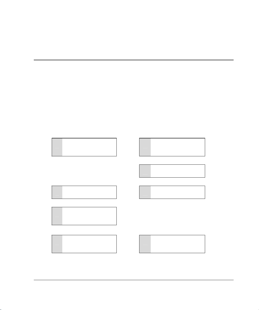
The details of the steps required to install the controller depend on whether the server
has an operating system installed and contains data. The flowcharts in Figure 1-1 and
Figure 1-2 summarize the installation procedures for the most common scenarios.
Procedure for a New System
Install the controller
1
hardware (Chapter 2), if
it is not preinstalled.
Set the boot controller
5
(Chapter 4).
Create at least one
6
logical drive and format
it (Chapter 5).
:
:
. . . . . . .
. . . . . . .
Installation Overview
Update the system
2
firmware (Chapter 3).
Update the controller
3
firmware (Chapter 3).
Configure the system
4
(Chapter 4).
:
:
1
Install the operating
7
system and device
drivers (Chapter 6).
Figure 1-1: Controller installation in a new system
HP Smart Array 641/642 Controller User Guide 1-1
. . . . . . .
Create and format
8
additional logical drives
if desired (Chapter 5).
Page 12
Installation Overview
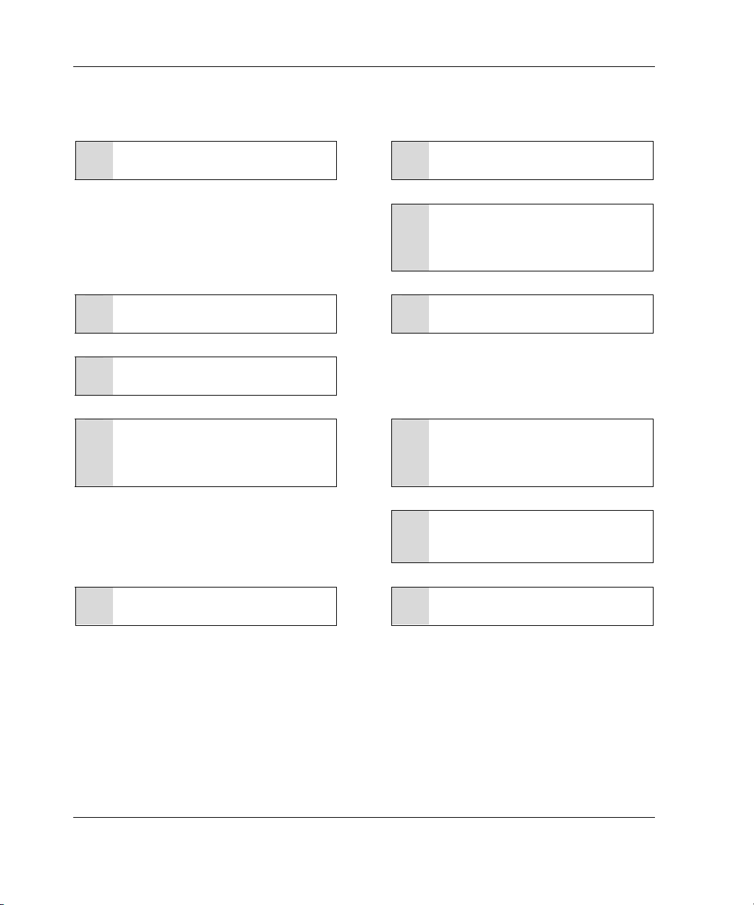
Procedure for a Preconfigured System
Back up data (required if migrating
1
from a non-array controller).
Set the controller order (Chapter 4).
5
Update the controller firmware
6
(Chapter 3).
If using the System Configuration
7
Utility, update the system partition
(Chapter 3), and then check the
controller order (Chapter 4).
If migrating from a non-array
11
controller, restore data from backup.
:
:
- - - - -
- - - - -
- - - - -
- - - - -
Update the system firmware
2
(Chapter 3).
If the controller is to be the boot
3
device, install the device driver for
the operating system (Chapter 6).
Otherwise, continue with step 4.
Install the controller hardware
4
(Chapter 2).
If the controller is not to be the boot
8
device, install the device driver for
the operating system (Chapter 6).
Update the Management Agents if
9
new versions are available
(Chapter 6).
Create and format new logical
10
drives as desired (Chapter 5).
:
:
:
:
Figure 1-2: Controller installation in an already
configured system
1-2 HP Smart Array 641/642 Controller User Guide
Page 13
Preparing the Server
Before installing the controller in the server, back up all data. This step is mandatory
if you are moving non-arrayed SCSI drives to a Smart Array controller, because data
is not preserved during a move between array controllers and non-array controllers.
WARNING: To reduce the risk of personal injury or damage to the equipment,
consult the safety information and user documentation provided with the
computer before attempting the installation.
Many computers are capable of providing energy levels that are considered
hazardous, and are only intended to be serviced by qualified personnel trained
in dealing with these hazards. Do not remove enclosures or attempt to bypass
any interlocks that may be provided for the purpose of removing these
hazardous conditions.
2
Installing the Hardware
If the server supports hot-pluggable devices, go directly to the “Installing the Smart
Array Controller” section.
To prepare a server that does not support hot-pluggable devices:
1. Close all applications.
2. Power down the server.
CAUTION: In systems using external data storage, be sure that the server is the
first unit powered down and the last unit to be powered back up. This precaution
ensures that the system will not erroneously mark the drives as failed.
3. Power down any peripheral devices that are attached to the server.
HP Smart Array 641/642 Controller User Guide 2-1
Page 14

Installing the Hardware
4. Unplug the AC power cord from the outlet, and then from the server.
5. Disconnect any peripheral devices from the server.
Installing the Smart Array Controller
1. Remove or open the access panel.
2. Select an available 3.3-V PCI or PCI-X slot.
3. Remove the slot cover or open the hot-plug latch. Save the retaining screw, if one
is present.
4. Slide the controller board along the slot alignment guide, and press the board
firmly into the slot so that the contacts on the board edge are properly seated in
the system board connector.
5. Secure the controller board in place with the hot-plug latch or retaining screw.
6. Continue by following the instructions given in “Connecting the Cables.”
Connecting the Cables
Each peripheral that is connected to the server must have a unique SCSI ID value,
falling in the range from 0 to 15 (except ID 7, which is reserved for controller use).
The SCSI ID value determines the priority that is given to the device when it attempts
to use the SCSI bus.
On products that support hot-pluggable devices, the SCSI IDs for such peripherals
are automatically set. The IDs for non-hot-pluggable devices must be set manually by
using switches or jumpers on the device itself.
SCSI buses require termination on both ends to prevent signal degradation. In all
Compaq servers and storage systems, and the newer ProLiant systems, the controller,
SCSI cable, and backplane already provide this termination.
Internal Cabling
1. If the device is not hot pluggable, power down the system.
2-2 HP Smart Array 641/642 Controller User Guide
Page 15
Installing the Hardware
2. Install drives into the removable media bays on the server. (For additional
information about drive installation, consult the documentation that accompanied
the drives, and refer to Appendix E.)
NOTE: Drives that are to be grouped in the same array should have the same capacity.
— If the drives are hot pluggable, go to step 3.
— If the drives are not hot pluggable, go to step 4.
3. Attach the internal point-to-point SCSI cable (provided with the server) from the
internal connector of the controller to the hot-plug drive cage.
Installation of the hot-pluggable drives is complete.
4. For each SCSI bus, manually set the SCSI ID on each drive to a unique value in
the range of 0 to 15, except 7 (which is reserved for controller use). For detailed
instructions, consult the documentation that is provided with the drive.
5. Attach the multi-device SCSI cable from the internal connector of the controller
to the non-hot-pluggable hard drives.
The multi-device cable may have been provided with the server. If you need
additional cables, order the cable option kit, Part Number 166389-B21. This
cable is equipped to terminate Ultra2, Ultra160 (Ultra3), or Ultra320 (Ultra4)
drives.
CAUTION: Cable assembly 148785-001 is included in option kit 166389-B21
and is required with Ultra3 and Ultra4 drives. Failure to use this cable may result
in reduced performance, data loss, or both.
External Cabling (Model 642 only)
1. On the rear of the server, connect the cable to the VHDCI connector on the
controller, and then tighten the lock screws on the cable connector.
2. Attach the other end of the cable to the storage enclosure, and then tighten the
lock screws on the cable connector.
3. Replace the access panel and secure it with the thumbscrews, as required.
HP Smart Array 641/642 Controller User Guide 2-3
Page 16
Installing the Hardware
CAUTION: Do not operate the server with the access panel removed for
extended periods of time. This precaution protects thermally sensitive
components by ensuring the proper airflow through the server, and minimizes
personal contact with hazardous energy levels.
Table 2-1: External SCSI Cables for Storage Enclosures
Cable Type Length Option Kit Number Cable Assembly Number
VHDCI to VHDCI 1.8 m / 6 ft 341174-B21 313374-001
VHDCI to VHDCI
VHDCI to VHDCI 7.2 m / 24 ft 164604-B21 313374-004
VHDCI to VHDCI 11.7 m / 39 ft 150214-B21 313374-005
Note: If additional cables are required, order by the option kit number.
3.6 m / 12 ft
341175-B21 313374-002
2-4 HP Smart Array 641/642 Controller User Guide
Page 17

3
Updating the Firmware
You can update the firmware using the Smart Components, which are downloadable
from the HP website. Detailed instructions for using the Smart Components are given
on the Web page that contains the components.
NOTE: Some newer ProLiant servers automatically update the system and controller firmware
when they are powered up for the first time. To determine whether this situation is true for a
particular server, refer to the server-specific setup and installation guide.
Alternatively, if the server uses Microsoft Windows 2000 or Microsoft Windows NT
as the operating system, you can use one of the CDs that are supplied with the
controller to accomplish the firmware updates. Before using either CD, check the
Smart Components on the HP website to see whether newer versions of the firmware
upgrade files are available.
1. Insert the CD into the CD-ROM drive of the server.
— If the server was configured using the ROM-Based Setup Utility (RBSU),
use the SmartStart CD (version 6.0 or later).
— If the server did not use RBSU, use the Support Software CD.
If you want to run the firmware updates while offline, restart the server now, and
then wait for controller initialization to finish.
The ProLiant Storage Software license agreement page is displayed.
2. Click Agree.
The main ProLiant Storage Software screen is displayed.
3. Click ROM Update Utility.
4. Click the Updates tab.
HP Smart Array 641/642 Controller User Guide 3-1
Page 18

Updating the Firmware
5. Select Express or Custom mode, and follow the on-screen prompts and
instructions to update the firmware on the system and the controller.
If the server does not use RBSU, you now need to use the System Configuration
Utility (SCU) to update the system partition.
1. Locate the page on the HP website that contains SCU and follow the on-screen
instructions to create four SCU diskettes.
2. Insert SCU diskette #1 into the server diskette drive.
3. Restart the system.
4. Select System Configuration Utility from the menu or list of icons that is
displayed.
5. Follow the on-screen instructions to update or create and populate a system
partition.
6. Exit from SCU. If the server does not reboot or a CD error message is displayed,
press the Ctrl+Alt+Del keys to reboot the server manually.
3-2 HP Smart Array 641/642 Controller User Guide
Page 19

4
Setting the Controller Order
After installing the controller hardware and updating the firmware:
• Configure the server by using either RBSU or SCU. A brief description of the
procedure is given in this chapter; the server user guide provides more details.
IMPORTANT: When using SCU to reconfigure a system that uses a Smart Array 641 or
642 Controller as the boot controller, use ORCA immediately afterwards to check that
the controller order is unchanged. Reset the controller order if necessary.
NOTE: Some newer ProLiant servers configure themselves automatically when they are
powered up for the first time. To determine whether this situation is true for a particular
server, refer to the server-specific setup and installation guide.
• Set the boot controller by using RBSU or the Option ROM Configuration for
Arrays (ORCA) utility, as described in this chapter.
• Create at least one logical drive, as described in Chapter 5.
NOTE: Some newer ProLiant servers automatically create a logical drive and configure a
RAID level when they are powered up for the first time. For this sequence of events to
occur, the server must have fewer than seven internal hard drives, and the boot drive
must not have been written to. To determine whether this situation applies to a particular
server, refer to the server-specific setup and installation guide.
Using RBSU
RBSU is a system configuration utility that is embedded in the system ROM, and is
customized for the server that it is installed on.
HP Smart Array 641/642 Controller User Guide 4-1
Page 20

Setting the Controller Order
CAUTION: Not all servers support RBSU. Do not flash an RBSU-ROM image onto a
server that is already configured with SCU unless the update instructions specifically
state that upgrading from SCU to RBSU is supported. If the upgrade is not
supported, the consequences of upgrading are unpredictable and you may lose data.
To use RBSU:
1. Power up the server.
2. Press the F9 key when prompted during system startup.
The main RBSU screen is displayed.
3. Configure the system. (For detailed instructions, refer to the ROM-Based Setup
Utility User Guide.)
4. Select Boot Controller Order on the main RBSU screen and follow the
on-screen prompts to set the boot controller.
5. When you have finished using the utility, press the Esc key, and then press the
F10 key to confirm that you want to exit RBSU.
Using ORCA
Part of the startup sequence of a server is the Power-On Self-Test (POST). If the
array controller in the server supports ORCA, POST temporarily halts and an ORCA
prompt message is displayed for about five seconds. (If ORCA is not supported, the
prompt message is not displayed and the system continues with the startup sequence.)
1. Power up the server and let the system startup sequence begin.
2. While the prompt message is displayed, press the F8 key to start ORCA.
3. On the Main Menu screen, select Select as Boot Controller and follow the
prompts to set the boot controller for the system.
If you want to use ORCA to create logical drives, you do not need to exit the utility
yet. Continue using ORCA as described in Chapter 5.
4-2 HP Smart Array 641/642 Controller User Guide
Page 21

5
Configuring an Array
HP provides three utilities for manually configuring an array:
• Array Configuration Utility (ACU)—A versatile, browser-based utility that
provides maximum control over configuration parameters
• Option ROM Configuration for Arrays (ORCA)—A simple ROM-based
configuration utility that runs on all operating systems
• NetWare Online Array Configuration Utility (CPQONLIN)—A menu-driven
utility for NetWare
NOTE: If you want to copy a particular array configuration to several other servers on the
same network, use the Array Configuration Replicator (ACR) or the scripting capability of ACU.
ACR is provided in the SmartStart Scripting Toolkit, available at www.hp.com/servers/sstoolkit.
For background information about drive arrays and fault-tolerance (RAID) methods,
refer to Appendix D.
The following limitations apply to all configuration methods:
• For the most efficient use of drive space, do not mix drives of different capacity
within the same array. Each configuration utility treats all physical drives in an
array as if they have the same capacity as the smallest drive in the array. Excess
capacity of larger drives is wasted because it is unavailable for data storage.
• The probability that an array will experience a hard drive failure increases with
the number of hard drives in the array (for more detailed information, refer to
Appendix F). If you configure an array with RAID 5, keep the probability of
failure acceptably low by using no more than 14 drives.
HP Smart Array 641/642 Controller User Guide 5-1
Page 22

Configuring an Array
Table 5-1: Comparison of Utilities for Configuring an Array
ACU CPQONLIN ORCA
Uses a graphical interface + 0 0
Available in languages other than English + 0 0
Executable at any time + + 0
Available on CD + + 0
Uses a wizard to suggest the optimum
configuration for an unconfigured controller
Describes configuration errors + 0 0
Supports these operating systems:
Microsoft Windows 2000 + 0 +
Microsoft Windows NT + 0 +
Novell NetWare +* + +
Linux + 0 +
Allows these procedures:
Creation and deletion of arrays, logical drives + + +
Assignment of RAID level + + +
Sharing of spare drive among several arrays + + 0
Assignment of multiple spare drives per array + + 0
Setting of stripe size + + 0
Migration of RAID level or stripe size + + 0
Configuration of controller settings + + 0
Expansion of an array + + 0
Creation of multiple logical drives per array + + 0
Setting of boot controller 0 0 +
+ + 0
*NetWare can use ACU only when the system is offline.
5-2 HP Smart Array 641/642 Controller User Guide
Page 23
Using ACU
For detailed information about using ACU, refer to the HP Array Configuration
Utility User Guide.
Using ORCA
When a computer system is powered up, part of the startup sequence is the Power-On
Self-Test (POST). Any array controllers that are in the system are initialized while
POST is running. If the array controller supports ORCA, POST temporarily halts and
an ORCA prompt message is displayed for about five seconds. (If ORCA is not
supported, the prompt message is not displayed and the system continues with the
startup sequence.)
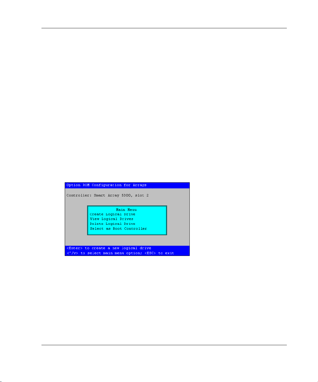
While the prompt is displayed, press the F8 key to start ORCA. The ORCA main
menu is displayed, allowing you to select the boot controller for the system, or to
create, view, or delete a logical drive.
Configuring an Array
Figure 5-1: ORCA main menu screen
NOTE: The maximum allowable boot drive size with ORCA is 4 GB.
To create a logical drive:
1. Select Create Logical Drive.
The screen displays a list of all available (unconfigured) physical drives and the
valid RAID options for the system.
HP Smart Array 641/642 Controller User Guide 5-3
Page 24

Configuring an Array
NOTE: You can create only one logical drive at a time.
2. Use the arrow keys, space bar, and tab key to navigate around the screen and set
up the logical drive, including a spare drive if required.
NOTE: ORCA allows only one array to use a given online spare.
3. Press the Enter key to accept the settings.
4. Press the F8 key to confirm the settings and save the new configuration.
After several seconds, the Configuration Saved screen is displayed.
5. Press the Enter key to continue.
You can now create another logical drive by repeating the previous steps.
NOTE: Raw logical drives are invisible to the operating system. To make the new logical
drives available for data storage, format the logical drive using the instructions given in the
operating system documentation.
Using CPQONLIN
The NetWare Online Array Configuration utility (CPQONLIN) lets you configure
drive arrays without shutting down the server. It also indicates when a drive attached
to the array controller has failed, is undergoing expansion, or is waiting (queued) for
expansion or rebuild.
IMPORTANT: The maximum logical drive size in CPQONLIN is 512 GB.
To install CPQONLIN:
1. Load CPQRAID.HAM from the SmartStart CD, or from the Controller Support
Software CD and diskettes. (Detailed instructions are given in the README file
on the CD.)
2. Load CPQONLIN.NLM from the same source.
3. Open CPQONLIN.NLM and follow the on-screen instructions.
5-4 HP Smart Array 641/642 Controller User Guide
Page 25

Running CPQONLIN
1. Enter cpqonlin at the console prompt.
2. Use the arrow keys to highlight Array Configuration Utility, and then press the
Enter key.
3. From the list of controllers that is presented, select the one that you want to
configure.
— If no logical drives are configured for the controller, the auto-configuration
wizard screen (Figure 5-2) is displayed.
— If logical drives are present on the controller, the manual configuration
screen (Figure 5-3) is displayed.
Press the F1 key for online help at any time on either screen.
Automatic Configuration
Configuring an Array
Figure 5-2: CPQONLIN auto-configuration wizard screen
1. If the proposed logical configuration shown on the wizard screen is acceptable,
highlight the fault-tolerance level that you want for the logical drive and press the
Enter key. Otherwise, select Custom Configuration and continue the procedure
as described in the “Manual Configuration” section.
2. Press the Esc key to save the changes and return to the controller selection
screen.
3. Restart the system to apply the changes.
HP Smart Array 641/642 Controller User Guide 5-5
Page 26

Configuring an Array
NOTE: Raw logical drives are invisible to the operating system. To make the new logical
drives available for data storage, format the logical drive using the instructions given in the
operating system documentation.
Manual Configuration
Figure 5-3: Main manual configuration screen
Highlight the controller, array, or logical drive that you want to configure, and then
press the Enter key. The menu options for that item are shown in the panel on the
right-hand side of the screen. Table 5-2 lists the menu options for each item in the
Logical Configuration View panel. If an option is not applicable in any particular
case, it is not displayed in the panel.
5-6 HP Smart Array 641/642 Controller User Guide
Page 27

Configuring an Array
Table 5-2: Menu Options in CPQONLIN
CONTROLLER OPTIONS Menu
Controller Settings Rebuild Priority
Expand Priority
Accelerator Ratio
Create New Array Create Array Assign Drive
Assign Array
Remove Drive
Accept Changes
Physical Drives (Panel shows spare drives and unassigned hard drives.)
New Array (Panel shows physical view of new array.)
ARRAY OPTIONS Menu
Expand Array Expand Array Assign Drive
Accept Changes
Physical Drives (Panel shows spare drives and unassigned hard drives.)
New Array (Panel shows physical view of new array.)
Assign Spare Assign Spare Assign Drive
Accept Changes
Physical Drives (Panel shows spare drives and unassigned hard drives.)
New Array (Panel shows physical view of new array.)
Delete Entire Array
LOGICAL DRIVE OPTIONS Menu
Drive Settings Enable / Disable Cache
Delete
Fault Tolerance
Stripe Size
HP Smart Array 641/642 Controller User Guide 5-7
Page 28

Configuring an Array
Typical Manual Configuration Procedures in CPQONLIN
Creating a Custom Configuration for a New Array
1. In the Logical Configuration View panel, highlight the controller that you want
to configure and then press the Enter key.
2. In the Controller Options panel, choose Create New Array, and then press the
Enter key.
The screen now displays three panels: Create Array, Physical Drives, and New
Array.
3. In the Create Array panel, choose Assign Drive, and then press the Enter key.
The highlight automatically moves to the Physical Drives panel.
4. Select a drive and then press the Enter key.
IMPORTANT: Do not assign a group of physical drives to the same array unless they are
of the same capacity. If the drives have different capacities, the excess capacity of the
larger drives cannot be used by the array and is wasted.
The New Array panel lists the added drive, and the highlight automatically
returns to the Create Array panel.
5. Repeat steps 3 and 4 until you have finished assigning drives to the array.
NOTE: You can add spare drives to the array only when all data storage drives have
been assigned.
6. Choose Accept Changes and press the Enter key.
The main manual configuration screen is displayed again.
5-8 HP Smart Array 641/642 Controller User Guide
Page 29

Adding Spare Drives
To add spare drives to an array, the array controller must have at least one attached
drive that is unassigned, or is assigned as a spare to another array.
You can:
• Assign a different online spare to each array on the controller.
• Share one online spare among several arrays on the same controller, for efficient
use of drive capacity.
• Assign several online spares to just one array.
• Share several online spares among several arrays; this method provides the
greatest amount of protection for the largest number of arrays.
IMPORTANT: Assigning several spares to an array lets you postpone replacement of faulty
drives, but it does not increase the fault-tolerance level of any logical drives in the array. For
example, a logical drive in a RAID 5 configuration suffers irretrievable data loss if two physical
drives fail simultaneously, regardless of the number of spare drives assigned.
Any drive that you assign as an online spare for an array operates as the spare for
every fault-tolerant logical drive within that array.
Configuring an Array
When you select Assign Spare, only drives that qualify are displayed; for example,
drives with too small a capacity are not listed. If a drive that you expect to see is not
listed, press the Tab key (to switch to the physical drive view) and check the capacity
of the drive.
To add a spare:
1. In the Logical Configuration View panel, highlight the array that needs a spare,
and then press the Enter key.
2. Choose Assign Spare in the Array Options menu, and then press the Enter key.
3. Select the drive that you want as the spare, and then press the Enter key.
4. Press the Esc key to accept the new configuration and return to the main manual
configuration screen.
HP Smart Array 641/642 Controller User Guide 5-9
Page 30

Configuring an Array
Configuring the New Logical Drive
1. In the Logical Configuration View panel, highlight the new logical drive that
you want to configure, and then press the Enter key.
2. Select Fault Tolerance in the Logical Drive Options menu, and then press the
Enter key.
3. Choose the RAID level that you want and then press the Enter key.
4. Choose Stripe Size and then press the Enter key.
5. Choose the stripe size that you want and then press the Enter key.
6. Press the Esc key to accept the settings and return to the main manual
configuration screen.
Configuring the Controller Settings
The Controller Settings option allows you to choose the drive rebuild priority,
expansion priority, and accelerator ratio for all arrays on the controller.
• With a low priority setting, a rebuild or expansion takes place only when the
array controller is not busy handling normal I/O requests. This setting has
minimal effect on normal I/O operations. However, there is an increased risk that
data will be lost if another physical drive fails while the rebuild is in progress.
• With a high priority setting, the rebuild or expansion occurs at the expense of
normal I/O operations. Although performance is affected, this setting provides
better data protection because the array is vulnerable to additional drive failures
for a shorter time.
• At the medium priority setting, expansion or rebuild occurs for half of the time,
and normal I/O requests are handled during the rest of the time.
NOTE: Logical drives can be rebuilt only if they have been configured for fault tolerance (that
is, any RAID level other than RAID 0). Drive rebuild begins automatically after you have
replaced a failed physical drive in the array.
The accelerator read/write ratio determines the amount of memory allocated to the
read and write caches on the array accelerator. Different applications have different
optimum settings. Some controllers (especially those without battery-backed write
cache) do not allow this ratio to be changed.
5-10 HP Smart Array 641/642 Controller User Guide
Page 31

Configuring an Array
1. In the Logical Configuration View panel, select the controller that you want to
configure, and then press the Enter key.
2. In the Controller Options panel, select Controller Settings, and then press the
Enter key. The Controller Settings screen is displayed.
Figure 5-4: Controller Settings screen
3. Alter the settings on this screen to meet your requirements.
4. Press the Esc key to save the new configuration.
5. Exit CPQONLIN, and then restart the system to apply the changes.
Expanding an Array
Performance may be degraded slightly during array expansion, depending on the
Expand Priority setting. To minimize any effect, expand the array during periods of
low server use.
NOTE: The expansion process takes about 15 minutes per gigabyte. The controller is not able
to expand or migrate any other logical drive during this time. Instead, further requests for
expansion or migration are queued.
1. Back up all data on the logical drive. Although array expansion is unlikely to
cause data loss, observing this precaution provides extra security.
2. Highlight the controller in the Logical Configuration View panel, and then press
the F3 key. Scroll down the screen until you reach the Array Accelerator
section. The condition of the battery and cache should both be OK.
HP Smart Array 641/642 Controller User Guide 5-11
Page 32

Configuring an Array
3. Exit from the previous screen, and then move the highlight to the logical drive. If
the controller has a battery-backed write cache, there should be an entry Disable
Cache in the right-hand panel, implying that the cache is enabled. If the entry is
Enable Cache, the cache is currently disabled; enable it.
4. In the Logical Configuration View panel, select the array that you want to
expand, and then press the Enter key.
5. Select Expand in the menu, and then press the Enter key.
6. Select the hard drive that you want to add to the array, and then press the Enter
key.
IMPORTANT: Do not assign a group of physical drives to the same array unless they are
of the same capacity. If the drives have different capacities, the excess capacity of the
larger drives cannot be used by the array and is wasted.
7. Repeat step 6 until you have finished adding drives.
8. Select Accept Changes, and then press the Enter key.
9. Press the Esc key to begin the array expansion.
You can see the progress of the expansion at any time by pressing the F3 key and
then scrolling to the progress bar near the bottom of the screen.
Migrating RAID Level or Stripe Size
Performance may be degraded slightly during migration, depending on the Expand
(or Rebuild) Priority setting. To minimize any effect, migrate during periods of low
server use.
NOTE: The migration process takes about 15 minutes per gigabyte. The controller is not able
to expand or migrate any other logical drive during this time. Instead, further requests for
expansion or migration will be queued.
1. Back up all data on the logical drive. Although migration is unlikely to cause
data loss, observing this precaution provides extra security.
2. Highlight the controller in the Logical Configuration View panel, and then press
the F3 key. Scroll down the screen until you reach the Array Accelerator
section. The condition of the battery and cache should both be OK.
5-12 HP Smart Array 641/642 Controller User Guide
Page 33

Configuring an Array
3. Exit from the previous screen, and then move the highlight to the logical drive. If
the controller has a battery-backed write cache, there should be an entry Disable
Cache in the right-hand panel, implying that the cache is enabled. If the entry is
Enable Cache, the cache is currently disabled; enable it.
4. In the Logical Configuration View panel, select the logical drive that you want
to migrate and then press the Enter key.
5. Select Drive Settings, and then press the Enter key.
6. Change the RAID level or stripe size shown on this screen.
Table 5-3: Supported Stripe Sizes for a Given RAID Level
Fault-Tolerance Level Supported Stripe Sizes (KB) Default (KB)
RAID 0, RAID 1+0 8, 16, 32, 64, 128, 256 128
RAID 5, RAID ADG* 8, 16, 32, 64 16
*Not all controllers support RAID ADG.
Table 5-4: Optimum Stripe Size for a Given Application
Type of Server Application Suggested Stripe Size Change
Mixed read/write Accept the default value
Mainly sequential read (such
as audio/video applications)
Mainly write (such as image
manipulation applications)
*Not all controllers support RAID ADG
Use larger stripe sizes for best performance
Use smaller stripes for RAID 5, RAID ADG*
Use larger stripes for RAID 0, RAID 1+0
7. Press the Esc key to accept the changes and begin migration.
You can check the progress of the migration at any time by pressing the F3 key
and then scrolling to the progress bar near the bottom of the screen.
HP Smart Array 641/642 Controller User Guide 5-13
Page 34

Installing the Device Drivers
and Management Agents
Installing the Device Drivers
The drivers for the controller are located on the Support Software CD and on the
SmartStart CD. Updates are posted to
Using the Support Software CD: Instructions for installing the drivers from the
Support Software CD are given in the leaflet that is supplied with the CD. Note that
the exact procedure depends on whether the server is new or already contains the
operating system and user data.
Using the SmartStart CD: If you used the SmartStart Assisted Installation path to
install the operating system on a new server, the drivers are automatically installed at
the same time. You can also use SmartStart to update the drivers manually on older
systems. For further information, refer to the SmartStart documentation.
www.hp.com.
6
Updating the Management Agents
If you used the SmartStart Assisted Installation path to install the operating system on
a new server, the Management Agents are automatically installed at the same time.
The Management Agents can also be manually updated using the SmartStart CD or
the Management CD. For the procedure, refer to the documentation on the
Management CD or on
HP Smart Array 641/642 Controller User Guide 6-1
www.hp.com/servers/manage.
Page 35

Installing the Device Drivers and Management Agents
You can obtain the Management CD from your local HP reseller or authorized
service provider. The latest versions of Insight Manager and Management Agents are
also available for download at
www.hp.com/servers/manage.
If the new agents do not function correctly, you may also need to update
Insight Manager.
6-2 HP Smart Array 641/642 Controller User Guide
Page 36

7
Upgrading or Replacing the Cache
WARNING: There is a risk of explosion, fire, or personal injury if the battery
pack is not properly handled. Refer to Appendix B and the Battery
Replacement Notice in Appendix A before installing or removing the cache.
To remove the cache module, open the DIMM ejector latches (1) on each side of the
DIMM connector, and then pull the cache out of the DIMM slot (2).
2
1
This drawing represents the Smart Array 642 Controller. The cache on the Smart
Array 641 Controller is removed in an identical manner.
To replace the cache module, reverse this procedure.
HP Smart Array 641/642 Controller User Guide 7-1
Page 37

Regulatory Compliance Notices
Federal Communications Commission Notice
Part 15 of the Federal Communications Commission (FCC) Rules and Regulations
has established Radio Frequency (RF) emission limits to provide an interference-free
radio frequency spectrum. Many electronic devices, including computers, generate
RF energy incidental to their intended function and are, therefore, covered by these
rules. These rules place computers and related peripheral devices into two classes, A
and B, depending upon their intended installation. Class A devices are those that may
reasonably be expected to be installed in a business or commercial environment.
Class B devices are those that may reasonably be expected to be installed in a
residential environment (for example, personal computers). The FCC requires
devices in both classes to bear a label indicating the interference potential of the
device as well as additional operating instructions for the user.
The rating label on the device shows the classification (A or B) of the equipment.
Class B devices have an FCC logo or FCC ID on the label. Class A devices do not
have an FCC logo or FCC ID on the label. After the Class of the device is
determined, refer to the corresponding statement in the following sections.
A
HP Smart Array 641/642 Controller User Guide A-1
Page 38

Regulatory Compliance Notices
Class A Equipment
This equipment has been tested and found to comply with the limits for a Class A
digital device, pursuant to Part 15 of the FCC Rules. These limits are designed to
provide reasonable protection against harmful interference when the equipment is
operated in a commercial environment. This equipment generates, uses, and can
radiate radio frequency energy and, if not installed and used in accordance with the
instructions, may cause harmful interference to radio communications. Operation of
this equipment in a residential area is likely to cause harmful interference, in which
case the user will be required to correct the interference at personal expense.
Class B Equipment
This equipment has been tested and found to comply with the limits for a Class B
digital device, pursuant to Part 15 of the FCC Rules. These limits are designed to
provide reasonable protection against harmful interference in a residential
installation. This equipment generates, uses, and can radiate radio frequency energy
and, if not installed and used in accordance with the instructions, may cause harmful
interference to radio communications. However, there is no guarantee that
interference will not occur in a particular installation. If this equipment does cause
harmful interference to radio or television reception, which can be determined by
turning the equipment off and on, the user is encouraged to try to correct the
interference by one or more of the following measures:
• Reorient or relocate the receiving antenna.
• Increase the separation between the equipment and receiver.
• Connect the equipment into an outlet on a circuit that is different from that to
which the receiver is connected.
• Consult the dealer or an experienced radio or television technician for help.
A-2 HP Smart Array 641/642 Controller User Guide
Page 39

Regulatory Compliance Notices
Declaration of Conformity for Products Marked with the FCC Logo, United States Only
This device complies with Part 15 of the FCC Rules. Operation is subject to the
following two conditions: (1) this device may not cause harmful interference, and
(2) this device must accept any interference received, including interference that may
cause undesired operation.
For questions regarding your product, contact us by mail or telephone:
• Hewlett-Packard Company
P. O. Box 692000, Mail Stop 530113
Houston, Texas 77269-2000
• 1-800-652-6672 (For continuous quality improvement, calls may be recorded or
monitored.)
For questions regarding this FCC declaration, contact us by mail or telephone:
• Hewlett-Packard Company
P. O. Box 692000, Mail Stop 510101
Houston, Texas 77269-2000
• 1-281-514-3333
To identify this product, refer to the part, series, or model number found on the
product.
Modifications
The FCC requires the user to be notified that any changes or modifications made to
this device that are not expressly approved by Hewlett-Packard Company may void
the user’s authority to operate the equipment.
Cables
Connections to this device must be made with shielded cables with metallic RFI/EMI
connector hoods in order to maintain compliance with FCC Rules and Regulations.
HP Smart Array 641/642 Controller User Guide A-3
Page 40

Regulatory Compliance Notices
Canadian Notice (Avis Canadien)
Class A Equipment
This Class A digital apparatus meets all requirements of the Canadian
Interference-Causing Equipment Regulations.
Cet appareil numérique de la classe A respecte toutes les exigences du Règlement sur
le matériel brouilleur du Canada.
Class B Equipment
This Class B digital apparatus meets all requirements of the Canadian
Interference-Causing Equipment Regulations.
Cet appareil numérique de la classe B respecte toutes les exigences du Règlement sur
le matériel brouilleur du Canada.
Mouse Compliance Statement
This device complies with Part 15 of the FCC Rules. Operation is subject to the
following two conditions: (1) this device may not cause harmful interference, and
(2) this device must accept any interference received, including interference that may
cause undesired operation.
European Union Notice
Products with the CE Marking comply with both the EMC Directive (89/336/EEC)
and the Low Voltage Directive (73/23/EEC) issued by the Commission of the
European Community.
Compliance with these directives implies conformity to the following European
Norms (the equivalent international standards are in parentheses):
• EN55022 (CISPR 22) – Electromagnetic Interference
A-4 HP Smart Array 641/642 Controller User Guide
Page 41

• EN55024 (IEC61000-4-2, 3, 4, 5, 6, 8, 11) – Electromagnetic Immunity
• EN60950 (IEC950) – Product Safety
Japanese Notice
Regulatory Compliance Notices
Taiwanese Notice
HP Smart Array 641/642 Controller User Guide A-5
Page 42

Regulatory Compliance Notices
Battery Replacement Notice
The battery-backed write cache uses a nickel metal hydride (NiMH) battery pack.
WARNING: There is a risk of explosion, fire, or personal injury if the battery
pack is not properly handled. To reduce this risk:
• Do not try to recharge the batteries if they are disconnected from the
controller.
• Do not expose the battery pack to water, or to temperatures higher than
60°C.
• Do not abuse, disassemble, crush, or puncture the battery pack.
• Do not short the external contacts.
• Replace the battery pack only with the designated HP spare.
Battery disposal should comply with local regulations. Alternatively, use
established parts return methods to return the battery pack to HP for disposal.
Batteries, battery packs, and accumulators should not be disposed of
together with the general household waste. To forward them to recycling or
proper disposal, use the public collection system or return them to HP, your
authorized HP Partners, or their agents.
For more information about battery replacement or proper disposal, contact your HP
authorized reseller or your authorized service provider.
A-6 HP Smart Array 641/642 Controller User Guide
Page 43

B
Electrostatic Discharge
To prevent damaging the system, be aware of the precautions you need to follow
when setting up the system or handling parts. A discharge of static electricity from a
finger or other conductor may damage system boards or other static-sensitive
devices. This type of damage may reduce the life expectancy of the device.
To prevent electrostatic damage, observe the following precautions:
• Avoid hand contact by transporting and storing products in static-safe containers.
• Keep electrostatic-sensitive parts in their containers until they arrive at static-free
workstations.
• Place parts on a grounded surface before removing them from their containers.
• Avoid touching pins, leads, or circuitry.
• Always be properly grounded when touching a static-sensitive component or
assembly.
There are several methods for grounding. Use one or more of the following methods
when handling or installing electrostatic-sensitive parts:
• Use a wrist strap connected by a ground cord to a grounded workstation or
computer chassis. Wrist straps are flexible straps with a minimum of 1 megohm
resistance in the ground cords. To provide proper ground, wear the strap snug
against the skin.
• Use heel straps, toe straps, or boot straps at standing workstations. Wear the
straps on both feet when standing on conductive floors or dissipating floor mats.
• Use conductive field service tools.
HP Smart Array 641/642 Controller User Guide B-1
Page 44

Electrostatic Discharge
• Use a portable field service kit with a folding static-dissipating work mat.
If you do not have any of the suggested equipment for proper grounding, have an HP
authorized reseller install the part.
NOTE: For more information on static electricity, or assistance with product installation,
contact your HP authorized reseller.
B-2 HP Smart Array 641/642 Controller User Guide
Page 45

Controller Specifications
Table C-1: Controller Specifications
Dimensions (PCB only) 28.7 cm × 10.8 cm × 1.6 cm (11.3 in × 4.3 in × 0.63 in)
Power required No more than 14 W for either model
PCI-X bus transfer rate Up to 1064 MB/s at 133 MHz (64-bit)
C
Temperature range
Relative humidity (noncondensing) Operating: 20% to 80%
RAID levels supported 0, 1+0, 5
SCSI Bus:
Number of channels 1 internal (641); 1 internal and 1 external (642)
Maximum number of drives per
channel
Connector type 68-pin Wide internal, VHDCI external
Termination Required, but provided on Compaq and newer HP systems
Transfer rate Up to 320 MB/s (80 MHz) per channel
Operating: 10° to 35°C (50° to 95°F)
Storage: –30° to 60°C (–22° to 140°F)
Storage: 5% to 90%
15 (14 in an external enclosure)
For more information about the controller features and specifications, refer to
www.compaq.com/smartarray.
HP Smart Array 641/642 Controller User Guide C-1
Page 46

Drive Arrays and Fault Tolerance
What Is a Drive Array?
The capacity and performance of a single physical (hard) drive is adequate for home
users. However, business users demand higher storage capacities, higher data transfer
rates, and greater protection against data loss when drives fail.
Connecting extra physical drives to a system increases the total storage capacity
(refer to Figure D-1), but has no effect on the efficiency of read/write (R/W)
operations. Data can still be transferred to only one physical drive at a time.
D
R/W
P1 P2 P3
Figure D-1: Physical drives added to system
HP Smart Array 641/642 Controller User Guide D-1
Page 47

Drive Arrays and Fault Tolerance
With an array controller installed in the system, the capacity of several physical
drives can be combined into one or more virtual units called logical drives (also
called logical volumes). Then, the read/write heads of all the constituent physical
drives are active simultaneously, reducing the total time required for data transfer.
P1 P2 P3
Figure D-2: Physical drives configured into a logical
drive (L1)
L1
Because the read/write heads are active simultaneously, the same amount of data is
written to each drive during any given time interval. Each unit of data is called a
block, and adjacent blocks form a set of data stripes across all the physical drives
that comprise the logical drive (refer to Figure D-3).
D-2 HP Smart Array 641/642 Controller User Guide
Page 48

Drive Arrays and Fault Tolerance
S1
S2
S3
S4
B1
B4
B7
B2
B5
B8
B11B10 B12
B3
B6
B9
Figure D-3: Data striping (S1-S4) of data blocks B1-B12
For data in the logical drive to be readable, the data block sequence must be the same
in every stripe. This sequencing process is performed by the array controller, which
sends the data blocks to the drive write heads in the correct order.
A natural consequence of the striping process is that each physical drive in a given
logical drive will contain the same amount of data. If one physical drive has a larger
capacity than other physical drives in the same logical drive, the extra capacity is
wasted because it cannot be used by the logical drive.
The group of physical drives containing the logical drive is called a drive array (or
just array). Since all the physical drives in an array are commonly configured into
just one logical drive, the term array is also often used as a synonym for logical drive.
However, an array can contain several logical drives, each of a different size (refer to
Figure D-4).
HP Smart Array 641/642 Controller User Guide D-3
Page 49

Drive Arrays and Fault Tolerance
A1
L1
L2
A2
L3
L4
L5
Figure D-4: Two arrays (A1, A2) containing five logical
drives spread across five physical drives
Each logical drive in an array is distributed across all of the physical drives within the
array. A logical drive can also extend across more than one port on the same
controller, but it cannot extend across more than one controller.
Drive failure, although rare, is potentially catastrophic. In Figure D-4, for example,
failure of any physical drive causes all logical drives in the same array to fail, and all
data on the drives is lost.
To protect against data loss due to physical drive failure, logical drives are
configured with fault tolerance. There are several fault-tolerance methods; those that
are described in this appendix are:
• RAID 0—Data Striping only (no fault tolerance)
• RAID 1+0—Drive Mirroring
• RAID 5—Distributed Data Guarding
• RAID ADG—Advanced Data Guarding
D-4 HP Smart Array 641/642 Controller User Guide
Page 50

For any configuration except RAID 0, further protection against data loss can be
achieved by assigning a drive as an online spare (or hot spare). This drive contains
no data and is connected to the same controller as the array. When any other physical
drive in the array fails, the controller automatically rebuilds information that was
originally on the failed drive to the online spare. The system is quickly restored to
full RAID-level data protection. (However, in the unlikely event that another drive in
the array fails while data is being rewritten to the spare, the logical drive will still
fail.)
When you configure an online spare, it is automatically assigned to all logical drives
in the same array. Additionally, you do not need to assign a separate online spare to
each array; you can configure one hard drive to be the online spare for several arrays,
as long as the arrays are all on the same controller.
Fault-Tolerance Methods
RAID 0—No Fault Tolerance
This configuration (refer to Figure D-3) provides data striping, but there is no
protection against data loss when a drive fails. However, it is useful for rapid storage
of large amounts of non-critical data (for printing or image editing, for example), or
when cost is the most important consideration.
Drive Arrays and Fault Tolerance
Advantages
• Highest performance method for writes
• Lowest cost per unit of stored data
• All drive capacity is used to store data (none needed for fault tolerance)
Disadvantages
• All data on the logical drive is lost if a physical drive fails
• Cannot use an online spare
• Can only preserve data by backing it up to external drives
HP Smart Array 641/642 Controller User Guide D-5
Page 51

Drive Arrays and Fault Tolerance
RAID 1+0—Drive Mirroring
In this configuration, data is duplicated to a second drive.
B1
B2
B3
B4
P1 P2
B1
B2
B3
B4
Figure D-5: Drive mirroring of P1 to P2
When the array has more than two physical drives, drives are mirrored in pairs.
S1
S2
B1
B5
P1
P5
B2
B6
P2
P6
B3
B7
P3
P7
B4
B8
P4
P8
S1
S2
B1
B5
B2
B6
B3
B7
B4
B8
Figure D-6: Mirroring with more than two physical
drives in the array
D-6 HP Smart Array 641/642 Controller User Guide
Page 52

In each mirrored pair, the physical drive that is not busy answering other requests
answers any read request sent to the array. (This behavior is called load balancing.)
If a physical drive fails, the remaining drive in the mirrored pair can still provide all
the necessary data. Several drives in the array can fail without incurring data loss, as
long as no two failed drives belong to the same mirrored pair.
This fault-tolerance method is useful when high performance and data protection are
more important than the cost of physical drives.
NOTE: When there are only two physical drives in the array, this fault-tolerance method is
often referred to as RAID 1.
Advantages
• Highest read and write performance of any fault-tolerant configuration
• No loss of data as long as no failed drive is mirrored to another failed drive (up to
half of the physical drives in the array can fail)
Disadvantages
• Expensive (many drives needed for fault tolerance)
Drive Arrays and Fault Tolerance
• Only half of total drive capacity usable for data storage
RAID 5—Distributed Data Guarding
By this method, a block of parity data is calculated for each stripe from the data that
is in all other blocks within that stripe. The blocks of parity data are distributed over
every physical drive within the logical drive (refer to Figure D-7). When a physical
drive fails, data that was on the failed drive can be calculated from the user data on
the remaining drives and the parity data. This recovered data is usually written to an
online spare in a process called a rebuild.
HP Smart Array 641/642 Controller User Guide D-7
Page 53

Drive Arrays and Fault Tolerance
Figure D-7: Distributed data guarding, showing parity
information (Px,y)
This configuration is useful when cost, performance, and data availability are equally
important.
Advantages
• High read performance
• No loss of data if one physical drive fails
• More drive capacity usable than with RAID 1+0—parity information requires
only the storage space equivalent to one physical drive
S1
S2
S3
S4
B1
B3
P5,6
B7
B2
P3,4
B5
B8
P1,2
B4
B6
P7,8
Disadvantages
• Relatively low write performance
• Loss of data if a second drive fails before data from the first failed drive is rebuilt
D-8 HP Smart Array 641/642 Controller User Guide
Page 54

RAID ADG—Advanced Data Guarding
NOTE: Not all controllers support RAID ADG.
RAID ADG is similar to RAID 5, because both methods generate and store parity
information to protect against data loss caused by drive failure. With RAID ADG,
however, two different sets of parity data are used, allowing data to still be preserved
if two drives fail. Each set of parity data uses up a capacity equivalent to that of one
of the constituent drives, as shown in Figure D-8.
Drive Arrays and Fault Tolerance
Figure D-8: Advanced data guarding (RAID ADG)
This method is most useful when data loss is unacceptable, but cost is also an
important factor. The probability that data loss will occur when arrays are configured
with RAID ADG is less than when they are configured with RAID 5 (for details,
refer to Appendix F).
Advantages
• High read performance
• High data availability—any two drives can fail without loss of critical data
• More drive capacity usable than with RAID 1+0—parity information requires
only the storage space equivalent to two physical drives
B1
B3
P5,6
Q7,8
B2
P3,4
Q5,6
B7
P1,2
Q3,4
B5
B8
Q1,2
B4
B6
P7,8
HP Smart Array 641/642 Controller User Guide D-9
Page 55

Drive Arrays and Fault Tolerance
Disadvantage
The main disadvantage of RAID ADG is a relatively low write performance (lower
than RAID 5), because of the need for two sets of parity data.
Comparison of RAID Methods
Table D-1 summarizes the important features of the different kinds of RAID methods
described here. The decision chart in Table D-2 may help you to determine which
option is best for your situation.
Table D-1: Summary of RAID Methods
RAID 0 RAID 1+0 RAID 5 RAID ADG*
Alternative name Striping (no
fault tolerance)
Usable drive space** 100% 50% 67% to 93% 50% to 96%
Usable drive space
formula
Minimum number of
physical drives
Tolerates failure of
one physical drive?
Tolerates
simultaneous failure
of more than one
physical drive?
Read performance High High High High
Write performance High Medium Low Low
Relative cost Low High Medium Medium
*Not all controllers support RAID ADG.
**Values for usable drive space are calculated with these assumptions: (1) all physical drives in the
array have the same capacity; (2) online spares are not used; (3) no more than 14 physical drives
are used per array for RAID 5; (4) no more than 56 drives are used with RAID ADG.
n n/2 (n-1)/n (n-2)/n
1 2 3 4
No Yes Yes Yes
No Only if no two
Mirroring Distributed
Data Guarding
No Yes
failed drives are
in the same
mirrored pair
Advanced Data
Guarding
D-10 HP Smart Array 641/642 Controller User Guide
Page 56

Table D-2: Choosing a RAID Method
Most Important Also Important Suggested RAID Level
Fault tolerance Cost effectiveness RAID ADG*
I/O performance RAID 1+0
Cost effectiveness Fault tolerance RAID ADG*
I/O performance
Fault tolerance RAID 1+0
*Not all controllers support RAID ADG.
I/O performance
Cost effectiveness
Other Fault-Tolerance Options
Your operating system may also support software-based RAID or controller
duplexing.
Drive Arrays and Fault Tolerance
RAID 5 (RAID 0 if fault
tolerance is not required)
RAID 5 (RAID 0 if fault
tolerance is not required)
• Software-based RAID resembles hardware-based RAID, except that the
operating system works with logical drives as if they were physical drives. To
protect against data loss caused by physical drive failure, each logical drive must
be in a different array from the others.
• Controller Duplexing uses two identical controllers with independent, identical
sets of drives containing identical data. In the unlikely event of a controller
failure, the remaining controller and drives will service all requests.
However, the hardware-based RAID methods described in this appendix provide a
much more robust and controlled fault-tolerant environment. Additionally, controller
duplexing and software-based RAID do not support online spares, auto-reliability
monitoring, interim data recovery, or automatic data recovery.
If you decide to use one of these alternative fault-tolerance options, configure your
arrays with RAID 0 for maximum storage capacity and refer to your operating system
documentation for further implementation details.
HP Smart Array 641/642 Controller User Guide D-11
Page 57

Hard Drive Installation and Replacement
Each drive on a SCSI bus must have a unique ID value in the range 0 to 15 (except
ID 7, which is reserved for controller use). This SCSI ID value is set automatically on
hot-pluggable drives in ProLiant servers and storage systems, but values for other
drives must be set manually.
• Do not terminate the drives. The internal cabling in ProLiant servers provides the
required termination of the SCSI bus.
• Do not use drives of different capacity in the same array. The excess capacity of
larger drives cannot be used by the array and is wasted.
• Do not use hot-pluggable drives on the same SCSI bus as non-hot-pluggable
drives.
Drives can be of the Ultra2, Ultra160 (Ultra3), or Ultra320 (Ultra4) type.
General Information About Hard Drive Failure
E
When a hard drive fails, all logical drives that are in the same array are affected. Each
logical drive in an array may be using a different fault-tolerance method, so each
logical drive can be affected differently.
• RAID 0 configurations cannot tolerate drive failure. If any physical drive in the
array fails, all non-fault-tolerant (RAID 0) logical drives in the same array will
also fail.
• RAID 1+0 configurations can tolerate multiple drive failures as long as no failed
drives are mirrored to one another.
• RAID 5 configurations can tolerate one drive failure.
HP Smart Array 641/642 Controller User Guide E-1
Page 58

Hard Drive Installation and Replacement
• RAID ADG configurations can tolerate simultaneous failure of two drives.
If more hard drives fail than the fault-tolerance method allows, fault tolerance is
compromised and the logical drive fails. In this case, all requests from the operating
system are rejected with unrecoverable errors. The “Compromised Fault Tolerance”
section discusses possible ways to recover from this situation.
Recognizing Drive Failure
The LEDs on the front of each hard drive are visible through the front of the server or
external storage unit. When a drive is configured as a part of an array and attached to
a powered-up controller, the status of the drive can be determined from the
illumination pattern of these LEDs.
Table E-1 describes the meaning of the various LED combinations.
3
2
1
Figure E-1: Hard drive status LED indicators
E-2 HP Smart Array 641/642 Controller User Guide
Page 59

Hard Drive Installation and Replacement
Table E-1: Hard Drive Status from LED Illumination Pattern
(1) Activity (2) Online (3) Fault Meaning
On, off, or
flashing
On, off, or
flashing
On Flashing Off
On Off Off
Flashing Flashing Flashing
Off Off On OK to replace the drive online.
Off Off Off OK to replace the drive online if the array is configured
On or off Flashing A predictive failure alert has been received for this drive.
Replace the drive as soon as possible.
On Off OK to replace the drive online if the array is configured
for fault tolerance and all other drives in the array are
online.
The drive is online and configured as part of an array.
Do not remove the drive. Removing a drive during
this process may terminate the current operation and
cause data loss.
The drive is rebuilding or undergoing capacity expansion.
Do not remove the drive. Removing a drive during
this process may cause data loss.
The drive is being accessed, but (1) it is not configured
as part of an array; (2) it is a replacement drive and
rebuild has not yet started; or (3) it is spinning up during
the Power-On Self-Test (POST) sequence.
Do not remove the drive. Removing a drive during
this process can cause data loss in non-fault-tolerant
configurations.
Either (1) the drive is part of an array being selected by
ACU or CPQONLIN; or (2) Drive Identification has been
selected in Insight Manager.
The drive has failed and has been placed offline.
for fault tolerance and all other drives in the array are
online.
Either (1) the drive is not configured as part of an array;
(2) the drive is configured as part of an array, but a
powered-up controller is not accessing the drive; or
(3) the drive is configured as an online spare.
HP Smart Array 641/642 Controller User Guide E-3
Page 60

Hard Drive Installation and Replacement
There are several other ways to recognize that a hard drive has failed:
• The amber LED on the front of a storage system illuminates if failed drives are
inside. (Other problems such as fan failure, redundant power supply failure, or
over-temperature conditions also cause this LED to light up.)
• A Power-On Self-Test (POST) message lists failed drives whenever the system is
restarted, as long as the controller detects one or more good drives.
• ACU represents failed drives with a distinctive icon.
• Insight Manager can detect failed drives remotely across a network. (For more
information about Insight Manager, refer to the documentation on the
Management CD.)
• The Array Diagnostic Utility (ADU) lists all failed drives.
For additional information about diagnosing hard drive problems, refer to the Servers
Troubleshooting Guide.
Compromised Fault Tolerance
Compromised fault tolerance commonly occurs when more physical drives have
failed than the fault-tolerance method can endure. In this case, the logical volume is
failed and unrecoverable disk error messages are returned to the host. Data loss is
likely to occur.
An example of this situation is where one drive on an array fails while another drive
in the same array is still being rebuilt. If the array has no online spare, any logical
drives on the array that are configured with RAID 5 fault tolerance will fail.
Compromised fault tolerance may also be caused by non-drive problems, such as
temporary power loss to a storage system or a faulty cable. In such cases, the physical
drives do not need to be replaced. However, data may still have been lost, especially
if the system was busy at the time that the problem occurred.
E-4 HP Smart Array 641/642 Controller User Guide
Page 61

Procedure to Attempt Recovery
When fault tolerance has been compromised, inserting replacement drives does not
improve the condition of the logical volume. Instead, if the screen displays
unrecoverable error messages, try the following procedure to recover data.
1. Power down the entire system, and then power it back up. In some cases, a
marginal drive will work again for long enough to allow you to make copies of
important files.
2. If a 1779 POST message is displayed, press the F2 key to re-enable the logical
volumes. Remember that data loss has probably occurred and any data on the
logical volume is suspect.
3. Make copies of important data, if possible.
4. Replace any failed drives.
5. After the failed drives have been replaced, the fault tolerance may again be
compromised. If so, cycle the power again. If the 1779 POST message is
displayed, press the F2 key to re-enable the logical drives, recreate the partitions,
and restore all data from backup.
Hard Drive Installation and Replacement
To minimize the risk of data loss due to compromised fault tolerance, make frequent
backups of all logical volumes.
Automatic Data Recovery
Automatic Data Recovery is an automatic background process that rebuilds data to a
spare or replacement drive when another drive in the array fails. This process is also
called rebuild.
If a drive in a fault-tolerant configuration is replaced while the system power is off, a
POST message is displayed during the next system startup. This message prompts
you to press the F1 key to start automatic data recovery. If automatic data recovery is
not enabled, the logical volume remains in a ready-to-recover condition and the same
POST message is displayed whenever the system is restarted.
When automatic data recovery has finished, the Online LED of the replacement drive
stops blinking and begins to glow steadily.
HP Smart Array 641/642 Controller User Guide E-5
Page 62

Hard Drive Installation and Replacement
In general, approximately 15 minutes is required to rebuild each gigabyte. The actual
rebuild time depends on:
• The level of rebuild priority for the logical drive (this is set using one of the array
configuration utilities that are described in Chapter 5)
• The amount of I/O activity occurring during the rebuild operation
• The disk drive speed
• The number of drives in the array (for RAID 5 and RAID ADG)
For example, the rebuild time when using 9-GB drives in a RAID 5 configuration
varies from 10 minutes per gigabyte (for three drives) to 20 minutes per gigabyte (for
14 drives).
Failure of Automatic Data Recovery
If the Online LED of the replacement drive stops blinking during automatic data
recovery, there are three possible causes:
• If the Online LED is glowing continuously, automatic data recovery was
successful and has finished.
• If the amber failure LED is illuminated or other LEDs go out, the replacement
drive has failed and is producing unrecoverable disk errors.
Remove and replace the failed replacement drive.
• If the automatic data recovery process has abnormally terminated, one possible
cause is a non-correctable read error on another physical drive. The system may
temporarily become operational if rebooted. In any case, locate the faulty drive,
replace it, and restore data from backup.
General Aspects of Drive Replacement
Before replacing a degraded drive, use Insight Manager to examine the error counters
recorded for each physical drive in the array to confirm that such errors are not
presently occurring. Refer to the Insight Manager documentation on the Management
CD for details.
E-6 HP Smart Array 641/642 Controller User Guide
Page 63

Hard Drive Installation and Replacement
CAUTION: Sometimes, a drive that has previously been failed by the controller may
seem to be operational after the system is power-cycled, or (for a hot-pluggable
drive) after the drive has been removed and reinserted. However, continued use of
such marginal drives may eventually result in data loss. Replace the marginal drive
as soon as possible.
There are several other factors to remember when replacing a hard drive:
• Non-hot-pluggable drives should be replaced only while the system is powered
down.
• Hot-pluggable drives can be removed and replaced at any time, whether the host
or storage system power is on or off.
When a hot-pluggable drive is inserted, all disk activity on the array pauses while
the new drive is spinning up (usually 20 seconds or so). If the drive is inserted
while power is on, in a fault-tolerant configuration, data recovery to the
replacement drive begins automatically (indicated by the blinking Online LED).
• Replacement drives must have a capacity no less than that of the smallest drive in
the array. The controller immediately fails drives that have insufficient capacity,
before automatic data recovery can begin.
• When you set the SCSI ID jumpers manually, check the ID value to be sure that
the correct physical drive is being replaced. Set the same ID value on the
replacement drive to prevent SCSI ID conflicts.
CAUTION: In systems using external data storage, take care that the server is the
first unit to be powered down and the last to be powered back up. Doing this ensures
that the system does not erroneously mark the drives as failed when the server is
next powered up.
The rebuild operation takes several hours, even if the system is not busy while the
rebuild is in progress. System performance and fault tolerance are both affected until
the rebuild has finished. Therefore, replace drives during low activity periods
whenever possible. In addition, be sure that all logical volumes on the same array as
the drive being replaced have a current, valid backup.
HP Smart Array 641/642 Controller User Guide E-7
Page 64

Hard Drive Installation and Replacement
Drive Failure During Rebuild
If another drive in the array fails while fault tolerance is unavailable during rebuild, a
fatal system error may occur. If this happens, all data on the array is lost. In
exceptional cases, however, failure of another drive need not lead to a fatal system
error. These exceptions include:
• Failure after activation of a spare drive
• Failure of a drive that is not mirrored to any other failed drives (in a RAID 1+0
configuration)
• Failure of a second drive in a RAID ADG configuration
Minimizing Fatal System Errors During Rebuild
When a hard drive is replaced, the controller gathers fault-tolerance data from the
remaining drives in the array. This data is then used to rebuild the missing data
(originally on the failed drive) to the replacement drive. If more than one drive is
removed at a time, the fault-tolerance data is incomplete. The missing data cannot
then be reconstructed and is likely to be permanently lost.
To minimize the likelihood of fatal system errors, take these precautions when
removing failed drives:
• Do not remove a degraded drive if any other member of the array is offline (the
Online LED is off). In this condition, no other drive in the array can be removed
without data loss.
There are some exceptions:
— When RAID 1+0 is used, drives are mirrored in pairs. Several drives can be
in a failed condition simultaneously (and they can all be replaced
simultaneously) without data loss, as long as no two failed drives belong to
the same mirrored pair.
— When RAID ADG is used, two drives can fail simultaneously (and be
replaced simultaneously) without data loss.
— If an online spare has an unlit Online LED (it is offline), the degraded drive
can still be replaced.
E-8 HP Smart Array 641/642 Controller User Guide
Page 65

• Do not remove a second drive from an array until the first failed or missing drive
has been replaced and the rebuild process is complete. (When the rebuild is
complete, the Online LED on the front of the drive stops blinking.)
There are some exceptions:
— In RAID ADG configurations, any two drives in the array can be replaced
simultaneously.
— In RAID 1+0 configurations, any drives that are not mirrored to other
removed or failed drives can be simultaneously replaced offline without data
loss.
Moving Drives and Arrays
You can move drives to other ID positions on the same array controller. You can also
move a complete array from one controller to another (even if the controllers are on
different servers).
Before moving drives, these conditions must be met:
• The move will not result in more than 14 physical drives per channel.
Hard Drive Installation and Replacement
• No more than 32 logical volumes will be configured for a controller.
• No drives are failed or missing.
• The array is in its original configuration with no active spare drives.
• Capacity expansion is not running.
• Controller firmware is the latest version (recommended).
Some additional restrictions must be met when moving an array:
• All drives in the array must be moved at the same time.
• A drive array that is moved from a battery-backed array controller to one that is
not battery-backed can no longer undergo array capacity expansion, logical drive
capacity extension, or migration of RAID level or stripe size.
HP Smart Array 641/642 Controller User Guide E-9
Page 66

Hard Drive Installation and Replacement
• Do not move an array that is configured with RAID ADG to a controller that
does not support RAID ADG. Only controllers that support RAID ADG can
recognize a drive array that has this configuration.
When all the conditions have been met:
1. Back up all data before removing any drives or changing configuration. This step
is required if you are moving data-containing drives from a controller that is not
battery backed.
2. Power down the system.
3. Move the drives.
4. Power up the system.
A 1724 POST message is displayed, indicating that drive positions were changed
and the configuration was updated.
CAUTION: If a 1785 (Not Configured) POST message is displayed, power down
the system immediately to avoid data loss, and then return the drives to their
original locations.
5. Restore the data from backup if necessary.
You can now check the new drive configuration by running ORCA or ACU (for
details, refer to Chapter 5).
Upgrading Hard Drive Capacity
You can increase the storage capacity on a system by swapping drives one at a time
for higher capacity drives. This method is viable as long as a fault-tolerance method
is running, and can be done even if there are no available drive bays.
CAUTION: Since a data rebuild takes about 15 minutes per gigabyte, the system is
unprotected against drive failure for many hours, or even days, while the rebuild is in
progress.
To upgrade hard drive capacity:
1. Back up all data.
E-10 HP Smart Array 641/642 Controller User Guide
Page 67

2. Replace any drive. The data on the new drive is re-created from redundant
information on the remaining drives.
CAUTION: Do not replace any other drive until data rebuild on this drive is
complete.
3. When data on the new drive has been rebuilt (the Activity LED is no longer
illuminated), repeat the previous step for the other drives in the array, one at a
time.
When all drives have been replaced, you can use the extra capacity to create new
logical drives or extend existing logical drives.
Expanding and Extending Capacity
Array capacity expansion is the addition of physical drives to an array and the
redistribution of the pre-existing logical drives over the enlarged array.
Capacity expansion is carried out using one of the utilities described in Chapter 5.
For reconfiguration to occur online (that is, without shutting down the operating
system), the configuration utility must be running in the same environment as the
normal server applications. Also, online expansion is possible only in systems that
are using hot-pluggable drives.
Hard Drive Installation and Replacement
The expansion process is illustrated in Figure E-2, where the original array
(containing data) is shown with a dashed border, and the newly added drives are
shown unshaded (containing no data). The array controller adds the new drives to the
array and redistributes the original logical drives over the enlarged array, one logical
drive at a time. Each logical drive keeps the same fault-tolerance method in the
enlarged array that it had in the smaller array.
HP Smart Array 641/642 Controller User Guide E-11
Page 68

Hard Drive Installation and Replacement
+
Figure E-2: Array capacity expansion
The unused capacity on the enlarged array can now be used to create an additional
logical drive, with a different fault-tolerance setting if necessary.
Alternatively, the unused capacity can be used to increase the size of one of the
original logical drives; this process is logical drive capacity extension. Another
method for carrying out logical drive capacity extension is to delete an existing
logical drive and then to add the freed capacity to another logical drive.
Only ACU supports capacity extension. Also, not all operating systems allow
extension to be carried out while the system is online (refer to Chapter 5 for details).
E-12 HP Smart Array 641/642 Controller User Guide
Page 69

F
Probability of Logical Drive Failure
The probability that a logical drive will fail depends on the RAID level setting. If the
logical drive does not have an online spare, the following results apply.
• A RAID 0 logical drive fails if only one physical drive fails.
• A RAID 1+0 logical drive fails if any two failed physical drives are mirrored to
each other.
— The maximum number of physical drives that can fail without causing
failure of the logical drive is n/2, where n is the number of hard drives in the
array. In practice, a logical drive usually fails before this maximum is
reached. As the number of failed drives increases, it becomes increasingly
unlikely that a newly failed drive is not mirrored to a previously failed drive.
— The minimum number of physical drive failures that can cause the logical
drive to fail is two, if the two drives happen to be mirrored to each other. The
probability that this will happen decreases as the total number of hard drives
in the array increases.
• A RAID 5 logical drive fails if two physical drives fail.
• A RAID ADG logical drive fails when three physical drives fail.
At any given RAID level, the probability of logical drive failure increases as the
number of physical drives in the logical drive increases.
The graph in Figure F-1 provides more quantitative information. The data for this
graph is calculated from the mean time between failure (MTBF) value for a typical
physical drive, assuming that no online spares are present. If an online spare is added
to any of the fault-tolerant RAID configurations, the probability of logical drive
failure is further decreased.
HP Smart Array 641/642 Controller User Guide F-1
Page 70

Probability of Logical Drive Failure
RAID 0
RAID 5
RAID 1+0
RAID ADG
Increasing likelihood of logical drive failure > > >
1 6 11 16 21 26 31 36 41 46 51 56
Total number of physical drives in array
Figure F-1: Relative probability of logical drive failure
F-2 HP Smart Array 641/642 Controller User Guide
Page 71

Troubleshooting
Several diagnostic tools are useful for troubleshooting problems with arrays. The
most important are:
• Array Diagnostics Utility (ADU)
This utility is available as a download from the HP website. ADU error messages
are listed in the Servers Troubleshooting Guide.
• Power-On Self-Test (POST) Messages
Smart Array controllers produce diagnostic error messages at reboot. Many of
these POST messages are self-explanatory and suggest corrective actions for
troubleshooting. Detailed information about these messages is given in the
Servers Troubleshooting Guide.
• Server Diagnostics
This utility is available on the SmartStart CD. To use Server Diagnostics, insert
the SmartStart CD into the server CD-ROM tray. Click Agree when the license
agreement is displayed, and then select the Maintenance tab.
G
Click Server Diagnostics, and then follow the on-screen prompts and
instructions.
HP Smart Array 641/642 Controller User Guide G-1
Page 72

A
accelerator ratio setting, in
CPQONLIN 5-10
ACR (Array Configuration Replicator) 5-1
ACU (Array Configuration Utility) 5-1
ADG See RAID ADG
ADU (Array Diagnostics Utility) G-1
advanced data guarding See RAID ADG
alert, predictive failure E-3
array
adding hard drives to E-11
creating, with CPQONLIN 5-8
defined D-3
expansion of, in CPQONLIN 5-11
manual configuration of, using
CPQONLIN 5-6
manual configuration of, using
ORCA 5-3
mixing drive capacities in 5-1
moving E-9
online spares in D-5
physical limitations of D-4
array capacity expansion
description of E-11
procedure for, using CPQONLIN 5-11
setting priority of, in CPQONLIN 5-10
time required for 5-11
Array Configuration Replicator (ACR) 5-1
Array Configuration Utility (ACU) 5-1
array controller
Index
configuration of 5-1
dimensions of C-1
driver installation for 6-1
duplexing of D-11
installation of 1-1, 2-1
power requirements of C-1
Array Diagnostics Utility (ADU) G-1
array expansion See array capacity
expansion
auto-configuration wizard, in
CPQONLIN 5-5
automatic data recovery
description of E-5
limitation of D-11
B
batteries, recycling A-6
block of data, defined D-2
boot controller, setting 4-1
boot straps, using B-1
C
cables
FCC compliance statement for A-3
part numbers for 2-3
cabling instructions 2-2
cache, memory allocation to, in
CPQONLIN 5-10
capacity expansion See array capacity
expansion
HP Smart Array 641/642 Controller User Guide Index-1
Page 73

Index
capacity extension E-12
capacity upgrade of hard drives E-10
comparison
of ACU with ORCA 5-2
of different RAID methods D-10
of hardware-based RAID with software-
based RAID D-11
of logical drive failure risk for different
RAID levels F-2
of RAID methods with other fault-
tolerance methods D-11
configuration wizard, in CPQONLIN 5-5
configuring
array controller 5-1
controller settings, using
CPQONLIN 5-10
SCSI ID settings 2-2
system 4-1
controller
configuration of 5-1
dimensions of C-1
driver installation for 6-1
duplexing of D-11
installation of 1-1, 2-1
power requirement of C-1
controller installation
flowcharts for 1-1
precautions during 2-1
controller order, setting 4-1
controller settings, configuring, using
CPQONLIN 5-10
CPQONLIN
comparison of, with other configuration
utilities 5-2
using 5-4
D
data block, defined D-2
data protection methods
non-RAID D-11
RAID D-4
data rebuild time E-6
data recovery, automatic E-5
data stripes, defined D-2
data transfer rate C-1
Declaration of Conformity A-3
default stripe size 5-13
device drivers, installing 6-1
device priority, setting 2-2
diagnosing problems
error messages in POST G-1
general G-1
hard drive E-4
dimensions of controller C-1
distributed data guarding (RAID 5) D-7
drive array See array
drive failure
immediate, possible cause E-7
POST notification of E-4
probability graph F-2
replacing drive after E-7
drive mirroring (RAID 1+0) D-6
drive rebuild, setting priority of, in
CPQONLIN 5-10
drive status LEDs E-2
drivers, installing and updating 6-1
drives of different capacity on array 5-1
duplexing, controller D-11
E
electrostatic discharge B-1
error counters E-6
error messages
1724 E-10
1785 E-10
Not Configured E-10
ESD (electrostatic discharge) B-1
expanding an array
description of E-11
procedure for, using CPQONLIN 5-11
setting priority of, in CPQONLIN 5-10
time required for 5-11
extending a logical drive E-12
external cabling 2-3
Index-2 HP Smart Array 641/642 Controller User Guide
Page 74

Index
external storage, powering up and down 2-1
F
failure, hard drive
general information E-1
immediate, possible cause of E-7
failure, logical drive
cause of E-2
recovery from E-5
fault tolerance See also RAID methods
alternative methods of D-11
changing level of, in CPQONLIN 5-12
compromised E-4
controller duplexing as D-11
description of methods D-4
software-based RAID as D-11
stripe size and 5-13
FCC notices A-1
features
of ACU 5-2
of controller C-1
of CPQONLIN 5-2
of ORCA 5-2
of RAID methods D-10
Federal Communications Commission
notices A-1
firmware, updating 3-1
flowcharts, controller installation 1-1
protection against D-4
recognizing E-2
replacing drive after E-7
upon replacement, possible cause E-7
hard drive status LEDs, interpreting pattern
of E-3
hard drives
adding, to array E-11
assigning SCSI ID to 2-3
capacity of, restrictions on 5-1
different capacity of, on array 5-1
failure of E-1, E-6
hot-pluggable, using E-1
interpreting status LEDs on E-3
larger capacity, using, in array E-10
LEDs of E-2
minimum number of, for RAID D-10
moving E-9
replacing E-7
status lights on E-2
upgrading capacity of E-10
heel straps, using B-1
hot spare D-5
hot-plug drive
replacing E-7
using E-1
HP authorized reseller vi
I
G
graph, drive failure probability F-2
grounding methods B-1
H
hard drive failure
detection of E-4
fault tolerance and D-10
general information E-1
immediate, possible cause of E-7
multiple, simultaneous D-10
HP Smart Array 641/642 Controller User Guide Index-3
Insight Manager 6-2
drive failure detection with E-4
error counters in E-6
installing
controller hardware 2-1
controller, flowcharts for 1-1
CPQONLIN 5-4
device drivers 6-1
interim data recovery, limitation of D-11
internal cabling 2-2
Page 75

Index
J
jumpers, setting 2-2
L
LEDs on hard drives E-2
limitations on
ACU use 5-2
CPQONLIN use 5-2
drive movement E-9
hard drive capacity 5-1
number of logical drives allowed per
array 5-2
ORCA use 5-2
stripe size 5-13
load balancing, defined D-7
logical drive capacity extension E-12
logical drives
compared to array D-3
creation of, with CPQONLIN 5-10
creation of, with ORCA 5-3
defined D-2
enlarging (extending) E-12
failure of E-2, E-5
recovery of, options for E-5
M
manual configuration of array
using CPQONLIN 5-6
using ORCA 5-3
maximum number of hard drives
for RAID 5 D-10
for RAID ADG D-10
maximum stripe size 5-13
memory, allocation of, in CPQONLIN 5-10
migration, in CPQONLIN 5-12
minimum number of hard drives for
RAID D-10
mirroring of drives D-6
mouse compliance statement A-4
moving drives E-9
multi-device cable 2-3
multiple hard drive failure D-10
N
NetWare Online Array Configuration
Utility See CPQONLIN
no fault tolerance (RAID 0) D-5
O
online drive capacity upgrade E-10
online spare
adding, in CPQONLIN 5-9
defined D-5
limitations of D-5
use of, with alternative fault-tolerance
methods D-11
optimum stripe size 5-13
option kit part numbers for cables 2-3, 2-4
Option ROM Configuration for Arrays See
ORCA
options ROM, updating 3-1
ORCA (Option ROM Configuration for
Arrays)
comparison of, with other configuration
utilities 5-2
configuring array with 5-1
setting boot controller with 4-2
overview of installation process 1-1
P
parity data
in RAID 5 D-7
in RAID ADG D-9
part numbers for cables 2-3, 2-4
partition, creating 3-2
parts, handling and storing B-1
peripherals, SCSI ID of 2-2
physical drives See hard drives
POST messages
1724 E-10
Index-4 HP Smart Array 641/642 Controller User Guide
Page 76

Index
1785 E-10
general information G-1
Not Configured E-10
power requirements of controller C-1
powering system up and down, caution
for 2-1
precautions
against ESD B-1
for installing controller 2-1
for setting SCSI IDs 2-2
when replacing drives E-6, E-8
predictive failure alert E-3
protecting data
alternative methods D-11
RAID methods D-4
R
RAID 0 (no fault tolerance) D-5
RAID 1+0 (drive mirroring) D-6
RAID 5 (distributed data guarding) D-7
RAID ADG (advanced data guarding) D-9
RAID level, migrating, in
CPQONLIN 5-12
RAID methods See also fault tolerance
changing level of, in CPQONLIN 5-12
comparison with alternative fault-
tolerance methods D-11
comparison with each other D-10
selection chart for D-11
software-based D-11
stripe size and 5-13
summary of features D-10
RBSU (ROM-Based Setup Utility) 4-1
read cache, memory allocation to, in
CPQONLIN 5-10
rebuild
description of E-5
setting priority of, in CPQONLIN 5-10
time required for E-6
recovering data, general information
for E-5
replacing hard drive E-7, E-8
reprogramming ROM 3-1
resources
ACR (Array Configuration
Replicator) 5-1
ACU 5-1
ADU (Array Diagnostics Utility) G-1
automatic data recovery E-5
CPQONLIN 5-1
Insight Manager 6-2
Management Agents 6-2
ORCA 4-2, 5-1
POST G-1
RBSU 4-1
System Configuration Utility 3-2, 4-1
restrictions on
ACU use 5-2
CPQONLIN use 5-2
moving drives E-9
ORCA use 5-2
ROM, updating 3-1
ROM-Based Setup Utility (RBSU) 4-1
S
SCSI bus termination requirement 2-2
SCSI bus, termination of C-1, E-1
SCSI IDs, setting 2-2
SCU (System Configuration Utility) 3-2,
4-1
SmartStart CD, updating firmware
using 3-1
spare drives
adding to array, using CPQONLIN 5-9
adding to array, using ORCA 5-4
defined D-5
static-safe containers B-1
status LEDs, on drives E-2
storage capacity, expanding, using
CPQONLIN 5-11
stripe size, migrating, in CPQONLIN 5-12
striping data, defined D-2
summary of RAID method features D-10
HP Smart Array 641/642 Controller User Guide Index-5
Page 77

Index
Support Software CD, updating firmware
using 3-1
supported
number of logical drives per array 5-2
stripe sizes 5-13
symbols in text v
system configuration 4-1
System Configuration Utility 3-2, 4-1
system partition, creating 3-2
system ROM, updating 3-1
T
technical support v
telephone numbers v, vi
termination of SCSI bus 2-2, C-1, E-1
time needed
for data rebuild E-6
for expansion 5-11
for migration 5-12
troubleshooting See also POST messages
general G-1
hard drive problems E-2
U
Ultra3 SCSI cable 2-3
unrecoverable disk error message E-4
updating
device drivers 6-1
firmware 3-1
Management Agents 6-2
system partition 3-2
upgrading hard drive capacity E-10
utilities
ACR (Array Configuration
Replicator) 5-1
ACU 5-1
Array Diagnostics Utility G-1
CPQONLIN 5-1
Insight Manager 6-2
ORCA 4-2, 5-1
POST G-1
RBSU 4-1
System Configuration Utility 3-2, 4-1
W
Wide Ultra3 SCSI cable 2-3
wizard, in CPQONLIN 5-5
wrist straps B-1
write cache, memory allocation to, in
CPQONLIN 5-10
Index-6 HP Smart Array 641/642 Controller User Guide
 Loading...