

Page 1

TECHNICAL MANUAL
OPERATOR’S, ORGANIZATIONAL, DIRECT SUPPORT, AND
GENERAL SUPPORT MAINTENANCE MANUAL
(INCLUDING REPAIR PARTS AND SPECIAL TOOLS LISTS)
FOR
METER, AUDIO LEVEL TA-885/U
(HEWLETT-PACKARD MODEL 3555B)
(NSN 6625-00-255-1083)
TM 11-6625-2779-14&P
HEADQUARTERS, DEPARTMENT OF THE ARMY
11 MARCH 1980
Page 2

TM 11-6625-2779-14&P
This manual contains copyrighted material reproduced by permission of Hewlett-Packard Company. All rights are
reserved.
TECHNICAL MANUAL HEADQUARTERS
DEPARTMENT OF THE ARMY.
No. 11-6625-2779-14&P WASHINGTON, DC, 11 March 1980
OPERATOR'S, ORGANIZATIONAL, DIRECT SUPPORT AND GENERAL
SUPPORT MAINTENANCE MANUAL (INCLUDING REPAIR PARTS AND
SPECIAL TOOLS LISTS) FOR
METER, AUDIO LEVEL TA-885/U
(HEWLETT-PACKARD MODEL 3555B)
(NSN 6625-00-255-1083)
REPORTING ERRORS AND RECOMMENDING IMPROVEMENTS
You can help improve this manual. If you find any mistakes or if you know of a way to
improve the procedures, please let us know. Mail your letter or DA Form 2028 (Recommended
Changes to Publications and Blank Forms), or DA Form 2028-2 located in back of this manual
direct to Commander, US Army Communications and Electronics Materiel Readiness Command,
ATTN: DRSEL-ME-MQ, Fort Monmouth, NJ 07703.
In either case, a reply will be furnished direct to you.
This manual is an authentication of the manufacturer's commercial literature which, through usage, has been found to
cover the data required to operate and maintain this equipment. The manual was not prepared in accordance with
military specifications; therefore, the format has not been structured to consider categories of maintenance.
SECTION 0. INTRODUCTION
Scope ...............................................................................................................................0-1 0-1
Indexes of Publications .....................................................................................................0-2 0-1
Maintenance forms, records, and reports...........................................................................0-3 0-1
Administrative storage.......................................................................................................0-4 0-2
Destruction of Army electronics materiel............................................................................0-5 0-2
Reporting of equipment improvements recommendations (EIR).........................................0-6 0-2
Items comprising an operable equipment ..........................................................................0-7 0-3
I. GENERAL INFORMATION
Introduction.......................................................................................................................1-1 1-1
Accessory equipment supplied..........................................................................................1-9 1-2
Instrument identification....................................................................................................1-11 1-2
150 BAL modification........................................................................................................1-13 1-2
II. INSTALLATION
Inspection.........................................................................................................................2-1 2-1
Warranty exception...........................................................................................................2-3 2-1
Power requirements..........................................................................................................2-5 2-1
Three-conductor power cable ............................................................................................2-7 2-1
Battery..............................................................................................................................2-10 2-1
Installation and removal of battery.....................................................................................2-12 2-2
Cover removal...................................................................................................................2-15 2-2
Repackaging for shipment.................................................................................................2-17 2-2
III. OPERATING INSTRUCTIONS
Introduction.......................................................................................................................3-1 3-1
Controls, connectors and indicators...................................................................................3-4 3-1
Operation..........................................................................................................................3-6 3-1
Battery..............................................................................................................................3-8 3-1
Level and noise measurements.........................................................................................3-12 3-5
Level measurements.........................................................................................................3-14 3-5
Noise measurements ........................................................................................................3-28 3-7
Recorder compatibility.......................................................................................................3-41 3-8
Applications......................................................................................................................3-45 3-8
Transmission loss measurements.....................................................................................3-48 3-10
Para Page
i
Page 3

SECTION III. OPERATING INSTRUCTIONS (Cont.). Para Page
Crosstalk measurements...................................................................................................3-53 3-10
Identifying noise characteristics.........................................................................................3-57 3-10
Measurements in DBC ......................................................................................................3-64 3-11
Measurement procedures..................................................................................................3-67 3-12
150 BAL conversion..........................................................................................................3-69 3-12
IV. THEORY OF OPERATION
Introduction.......................................................................................................................4-1 4-1
Block diagram description.................................................................................................4-7 4-1
Detailed circuit description.................................................................................................4-16 4-2
Range attenuator A2.........................................................................................................4-18 4-3
Input amplifier A3..............................................................................................................4-20 4-3
Filters................................................................................................................................4-25 4-4
Meter amplifier..................................................................................................................4-30 4-7
Detector............................................................................................................................4-32 4-7
Power supply and series regulator.....................................................................................4-37 4-8
V. MAINTENANCE
Introduction.......................................................................................................................5-1 5-1
Factory selected values.....................................................................................................5-4 5-1
150 BAL conversion..........................................................................................................5-6 5-1
Performance Checks.........................................................................................................5-7 5-2
Adjustment and calibration procedure................................................................................5-14 5-8
Assembly removal.............................................................................................................5-25 5-10
Troubleshooting procedures..............................................................................................5-27 5-10
Factory selected values.....................................................................................................5-39 5-15
VI. REPLACEABLE PARTS
Introduction.......................................................................................................................6-1 6-1
Ordering information.........................................................................................................6-4 6-1
VII. CIRCUIT DIAGRAMS
Introduction.......................................................................................................................7-1 7-1
Functional block diagrams.................................................................................................7-3 7-1
Schematic diagrams .........................................................................................................7-5 7-1
APPENDIX A. REFERENCES.................................................................................................................. A-1
APPENDIX B. MAINTENANCE ALLOCATION
SECTION I. Introduction....................................................................................................................... B-1
Il. Maintenance allocation chart for Meter, Audio Level TA-885/U........................................... B-3
III. Tool and test equipment requirements for Meter, Audio Level TA-883/U ............................ B-4
IV. Remarks (Not applicable)
APPENDIX C. MANUAL BACKDATING CHANGES.................................................................................. C-1
ii
Page 4

Model 3555B Table of Contents
LIST OF ILLUSTRATIONS
Number Page Number Page
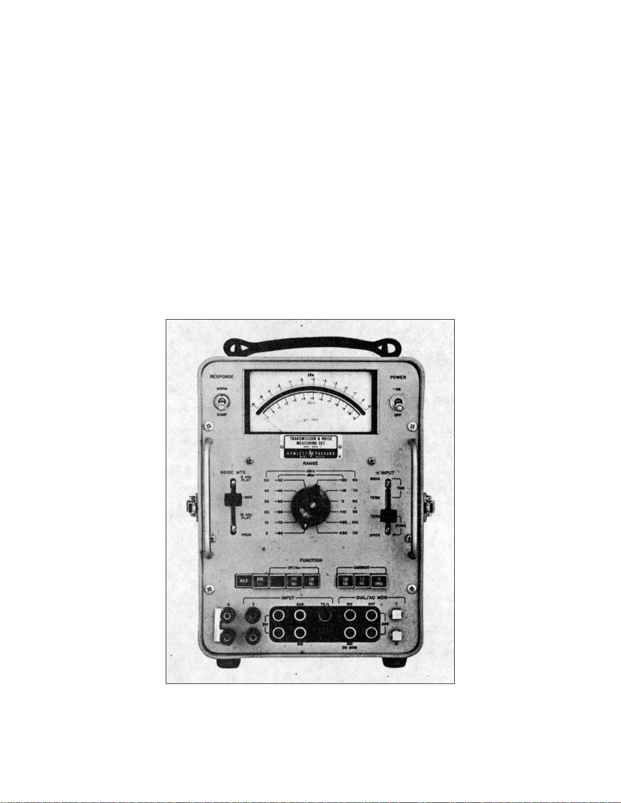
1-1.Model 3555B Transmission and
Noise Measuring Set..................................1-1 4-7.Simplified Peak Detection................................4-7
2-1.Power Plugs.................................................2-1 5-1.Balanced BNC to 310 Plug..............................5-2
3-1.Front Panel Controls, Indicators, 5-2.Level Accuracy Check.....................................5-2
and Connectors.........................................3-2 5-3.+20dBm and +30dBm Level
3-2.Side Panel Controls and Connectors.............3-4 Accuracy Check............................................5-4
3-3.Impedance Matching 3555B to Recorder......3-8 5-4.Return Loss Test Set-Up..................................5-5
3-4.Recorder Compatibility Chart........................3-9 5-5.Filter Response Test Set-Up............................5-5
3-5.Simplified Send/Receive Test Set-Up...........3-9 5-6.Bridging Loss Test Set-Up...............................5-6
3-6.Typical Test Set-Up for Measuring 5-7.Input Balance Test Set-Up...............................5-7
Insertion Loss..........................................3-10 5-8.Troubleshooting Tree.....................................5-11
3-7.Test Set-Up for Measuring 7-1.Functional Block Diagram..........................7-3/7-4
Crosstalk Coupling Loss..........................3-11 7-2.A1 Function Assembly Schematic and
3-8.Simple Test for Inductive and Component Location...............................7-5/7-6
Capacitive Coupling.................................3-12 7-3.A2 Range Attenuator and A3 Input
4-1.Simplified Block Diagram..............................4-1 Amplifier Schematic and Component
4-2.Simplified DIAL BAT Function......................4-2 Location..................................................7-7/7-8
4-3.Simplified NG Function.................................4-3 7-4.A4 Filter Schematic and Component
4-4. Simplified Average Detection........................4-4 Location................................................7-9/7-10
4-5.3kHz FLAT and PROGRAM 7-5.A3 Meter Amplifier, Detector and Series
Weighting Curves......................................4-5 Regulator Schematic and Component
4-6.C-MSG and 15kHz FLAT Locations............................................7-11/7-12
Weighting Curves......................................4-6
LIST OF TABLES
Number Page Number Page
1-1 Specifications...............................................1-0 5-1 Required Test Equipment................................5-1
1-2 Accessory Equipment Supplied.....................1-2 5-2 75 UNBAL Carrier Accuracy Check..................5-3
2-1 Suitable Batteries Meeting 5-3 Carrier 600 BAL and 135 BAL Level
NEDA 202 Specifications...........................2-1 Accuracy Check............................................5-3
3-1 Front, Side and Rear Panel Controls, 5-4 VF/Nm Level Accuracy Checks 600 BAL
Indicators and Connectors...................3-3/3-5 and 900 BAL -80 dBm Through +30 dBm.....5-4
3-2 Crosstalk Correction Factor........................3-10 5-5 Filter Response Checks...................................5-6
3-3 Level Measurement....................................3-13 5-6 Front Panel Trouble Analysis.................5-12/5-13
3-4 Noise Metallic Measurements.....................3-13 5-7 Function Troubleshooting...............................5-14
3-5 Noise-to-Ground Measurements.................3-14 5-8 FUNCTION Switch Resistance Values...........5-15
3-6 Balance Measurement................................3-14 5-9 Range Attenuation and Amplifier Gain...........5-16
3-7 Recorder Calibration...................................3-14 5-10 Resistance Checks........................................5-16
3-8 Transmission Loss Measurement................3-14 5-11 Factory Selected Values................................5-16
4-1 Range Attenuation and Amplifier Gain..........4-4 6-1 Replaceable Parts...........................................6-2
6-2 Part Number-National Stock Number
Cross Reference Index...............................6-10
iii
Page 5

SECTION 0
INTRODUCTION
0-1. Scope
This manual contains instructions for the operation, organizational maintenance and general support maintenance of
Audio Level Meter TA-885/U. Throughout this manual, the equipment is referred to by its commercial designation of
Hewlett-Packard Model 3555B Transmission and Noise Measuring Set or simply as the 3555B. Appendix A of the
manual contains a list of references and appendix B contains the maintenance allocation chart (MAC).
NOTE
No direct support maintenance functions are authorized for this equipment.
0-2. Indexes of Publications
a. DA Pam 310-4. Refer to the latest issue of DA Pam 310-4 to determine if there are any new editions,
changes, or additional publications pertaining to this equipment.
b. DA Pam 310-7. Refer to DA Pam 310-7 to determine if there are any modification work orders (MWO's)
pertaining to this equipment.
0-3. Maintenance Forms, Records, and Reports
a. Reports of Maintenance and Unsatisfactory Equipment. Department of the Army forms and procedures
used for equipment maintenance will be those described by TM 38-750, The Army Maintenance Management System.
0-1
Page 6

b. Report of Packaging and Handling Deficiencies. Fill out and forward DD Form 6 (Packaging Improvement
Report) as prescribed in AR 700-58/NAVSUPINST 4030.29/AFR 71-13/MCO P4030.29A, and DLAR 4145.8.
c. Discrepancy in Shipment Report (DISREP) (SF 361). Fill out and forward Discrepancy in Shipment Report
(DISREP) (SF 361) as prescribed in AR 55-38/NAVSUPINST 4610.33B/AFR 75-18 MCO P4610.19C and DLAR 4500.15.
0-4. Administrative Storage
Before placing the TA-885/U in temporary storage (90 days), determine the serviceability of the equipment by
performing the checks in paragraphs 5-7 through 5-13.
0-5. Destruction of Army Electronics Materiel
Destruction of Army electronics materiel shall be in accordance with the instructions in TM 750-244-2.
0-6. Reporting Equipment Improvement Recommendations (EIR)
If your TA-885/U needs improvement, let us know. Send us an EIR. You, the user, are the only one who can tell
us what you don't like about your equipment. Let us know why you don't like the design. Tell us why a procedure is hard
to perform. Put it on an SF 368 (Quality Deficiency Report). Mail it to Commander, US Army Communications and
Electronics Materiel Readiness Command, ATTN: DRSEL-ME MQ, Fort Monmouth, New Jersey 07703. We'll send you
a reply.
0-2
Page 7

0-7. Items Comprising an Operable Equipment
Audio Level Meter TA-885/U includes the meter, with cover and a power cord. The power cord is stored inside
the cover of the set.
0-3
Page 8

Section I Model 3555B
Table 1-1. Specifications
VOICE FREQUENCY LEVEL MEASUREMENTS (20Hz balanced and 75 ohms unbalanced.
to 20kHz) Return loss: TERM ONLY
600 ohms: 26dB min 3kHz to 150kHz
Range: -91dBm to +31dBm 135 ohms: 26dB min to 600kHz
75 ohms: 30dB min to 3MHz
Level accuracy: 20Hz to 20kHz: +0.5dB Bridging loss: less than 0.05dB at 10kHz
40Hz to 15kHz: +-0.2dB Balance:
(Levels greater than -60dBm) greater than 70dB to 10kHz
Note: For levels greater than +1 dBm, level accuracy greater than 60dB to 100kHz
specification applies only for frequencies above greater than 40dB to 600kHz
100Hz.
GENERAL
Input: will terminate or bridge 600 ohms or 900 ohms Temperature range: 0°F to 120°F 0 to 95% relative
balanced. humidity
Bridging loss: less than 0.3 dB at 1kHz. The 3555B will operate at -40°F under reduced
Return loss: 30dB min. (50Hz to 20kHz) TERM specifications. At this temperature, attention
Return loss: 30dB min. (50Hz to 2kHz) TERM should be given to noting condition of battery as
only. indicated on Battery Test (DIAL/BAT).
Balance:
greater than 80dB at 60Hz Meter: linear dB scale indicates rms value of input
greater than 70dB to 6kHz signal. 12dB range.
greater than 50dB to 20kHz Meter response
Holding circuit: 700 ohms dc resistance, 60mA Normal: 200ms to indicate a reading to 0dBm on
max. loop current at 300Hz. With holding circuit meter.
in, above specs apply from 300Hz to 4kHz. Damp: 500ms to indicate a reading to 0dBm on
meter.
NOISE MEASUREMENTS
Maximum input voltage
Range: -1 dBm to +121dBm Tip to ring: 150V peak
Tip or ring to ground: 500V peak
Weighting filters: 3kHz flat, 15kHz flat, C-message, and (This is maximum instantaneous voltage. Input
program. Meets joint requirements of Edison circuit will withstand 48V dc CO battery with
Electric Institute and Bell Telephone System. superimposed 90V rms 20Hz ringing voltage or
±130V carrier supply.)
Input: same as for level measurements.
Maximum longitudinal voltage: 200V rms at 60Hz
Noise to ground:
80 kilohms across line AC Monitor: 0.27V rms for 0dBm on meter.
100 kilohms to ground R
-40dB relative to 600 ohms noise metallic at jacks. Sufficient to drive WE 1011B or 52 type
1kHz. headset.
DC Monitor: 1 volt for 0dBm on meter. R
CARRIER FREQUENCY LEVEL MEASUREMENTS kilohms. Jack accepts 310 plug (tip negative).
(30Hz to 3MHz)
Input jacks: will accept Western Electric (WE) 241,
Range: -61dBm to +11dBm 309, 310, 358 plugs. Binding posts accept banana
Level accuracy: Removable shorting bar between sleeve and
600 ohms balanced ground binding posts.
1kHz to 150kHz: ±0.5dB Dial/AC Monitor jacks: will accept WE 289, 310, 347
135 ohms balanced (or 150 ohms balanced) plugs. Accepts WE 1011B lineman's handset or
1kHz to 600kHz: ±0.5dB 52 type headset.
10kHz to 300kHz: ±0.2dB
75 ohms unbalanced Power requirements:
100Hz to 600kHz: ±0.2dB Internal battery: single NEDA 202 45V "B"
30Hz to 1MHz: ±0.5dB battery included. Expected battery life - 180
1MHz to 3MHz: ±0.5dB ±10% of meter reading hours at 4 hours per day at 70° F.
in dBm. AC: 115V or 230V, 48-440Hz, <1W
Input: will terminate or bridge 600 ohms or 135 ohms accepts 310 plug (tip negative) less than 15mA.
= 8 kilohms. Available at DIAL/AC MON
out
= 2
out
plugs, spade lugs, phone tips or bare wires.
External battery: 24V or 48V office battery; jack
1-0
Page 9
Model 3555B Section I
SECTION I
GENERAL INFORMATION
1-1. INTRODUCTION.
1-2. The Hewlett-Packard Model 3555 B
Transmission and Noise Measuring Set is a versatile set
designed for uses in testing telecommunications
equipment. The extreme sensitivity of this set, linked
with its wide and flat frequency response, make it
suitable for noise and level measurements at voice,
program and carrier frequencies. Levels from -80dBm
to +30dBm (10dBm to +120dBm) full-scale can be
measured and displayed on a meter calibrated to
indicate both in dBm for level measurements and in
dBm for noise measurements.
1-3. The set combines the features of a voice and
noise frequency measuring set and the features of a
carrier frequency measuring set. For voice and program
frequencies impedances of 900 ohms and 600 ohms are
provided, balanced or unbalanced, bridged or
terminated. For noise measurements a noise-to-ground
(Ng) function is provided which provides 40dB of
attenuation for longitudinal noise. For carrier
frequencies 600 ohm, 135 ohm and 75 ohm impedances
are provided. The 600 and 135 function can be either
balanced or unbalanced, bridged or terminated; The 75
function is unbalanced only. Bridging impedance is over
100 kilohms, allowing measurements with a bridging
loss of less than 0.05dB. The meter indicates in dBm
for any selected input impedance.
1-4. The 3555B includes a 3kHz flat, a C-Message, a
Program and a 15kHz flat filter, each easily selectable
by a front panel control. These filters conform to the
standards set up .by the Bell System and Edison Electric
Institute. Other filters are available upon request.
Figure 1-1. Model 3555B Transmission and Noise Measuring Set
1-1
Page 10

Section I Model 3555B
1-5. A noise-to-ground (Ng) function is included
which permits the measurement of longitudinal noise.
When making noise-to ground measurements the
impedance between INPUT terminals is greater than 80
kilohms and is 100 kilohms between each terminal and
ground. A HOLD function permits holding the line while
noise measurements are being made. The input
circuitry provides 40dB of longitudinal noise attenuation
when noise-to-ground measurements are being made.
1-6. A DIAL/BAT function permits connecting a
lineman's handset to the line for the purpose of dialing
and at the same time connects the front panel meter to
the power supply so that the battery voltage or
unregulated power supply voltage can be monitored.
1-7. Jacks accepting Western Electric type 241, 309,
310, 347, and 358 plugs are provided for INPUT
connections to the 3555B. Dual binding posts accept
banana plugs, wires, lugs or phone tips and a pair of
special connectors permit the attachment of clip leads
from a lineman's handset.
1-8. The Model 3555B can be operated from either
the internal 45V dry cell battery or from the ac line, 115
or 230Vac, 48Hz to 440Hz. A special device is included
in the cover to automatically turn the set off when the
cover is replaced. The set can also be operated from
the central office battery. A jack is provided on the side
of the set for this purpose.
1-9. ACCESSORY EQUIPMENT SUPPLIED.
1-10. The accessory equipment supplied with the
Model 3555B is listed in Table 1-2.
Table 1-2. Accessory Equipment Supplied
-hp- Part No. Description Quantity
8120-1348 Power Cord 1
1470-0026 Battery, 45 Volt dry cell 1
03555-26510 Test Board 1
5000-7135 Decal, 150 BAL 1
1-11. INSTRUMENT IDENTIFICATION.
1-12. Hewlett-Packard uses a two-section serial
number. The first section (prefix) identifies a series of
instruments. The last section (suffix) identifies a
particular instrument within the series. If a letter is
included with the serial number, it identifies the country
in which the instrument was manufactured. If the serial
prefix of your instrument differs from the one on the title
page of this manual, a change sheet will be supplied to
make this manual compatable with newer instruments or
the backdating information in Appendix C will adapt this
manual to earlier instruments. All correspondence with
Hewlett-Packard should include the complete serial
number.
1-13. 150 BAL MODIFICATION.
1-14. The Model 3555B is shipped from the factory
with a 135 BAL function. If a 150 BAL function is
desired instead of the 135 BAL function, the set can be
converted by simply clipping a shorting wire within the
set, applying a 150 BAL decal (supplied with the set)
over the 135 BAL decal and making only one
adjustment.
1-15. For detailed instructions on modification of the
set refer to Paragraph 5-6. If your set is known to be
within specification tolerances a simplified procedure
can be used to modify the set and is described in
Paragraph 3-69.
1-2
Page 11
Model 3555B Section II
SECTION II
INSTALLATION
2-1. INSPECTION.
2-2. The set was carefully inspected both
mechanically and electrically before shipment. It should
be physically free of mars or scratches and in perfect
electrical condition on receipt. To confirm this, the set
should be inspected for physical damage in transit, for
supplied accessories and for electrical performance.
Paragraph 5-7 outlines the electrical performance
checks using test equipment listed in Table 5-1. If there
is damage or deficiency, see the warranty in the front of
this manual.
2-3. WARRANTY EXCEPTION.
2-4. The battery supplied with the 3555B is
warranted for a period of 60 days, beginning at the time
of receipt of the set. This warranty is based on an
expected battery life of 180 hours at 4 hours per day at
700 F as specified in Table 1-1 in this Manual.
2-5. POWER REQUIREMENTS.
2-6. This set is designed to operate from an internal
45 volt dry cell battery, an external 24 to 48 volt CO
battery or from an ac power source (115/230V, 48 to
440Hz). The power source is selected by the AC/BAT
switch on the side of the, set. The line voltage is
selected by the 115/230 volt slide switch on the rear of
the set. The set is protected by a 0.1 5A slow-blow fuse.
Table 2-1. Suitable Batteries Meeting
NEDA 202 Specifications
Manufacturer Mfr. Part No.
Hewlett-Packard 1420-0026
Western Electric KS-14370
Military BA-59
Eveready 482
Burgess M-30
RCA VS013
Bright Star 3033-158, 30-33
Mallory M-202
Ray-O-Vac 202, P7830
Sears 6461
Wards 42
Wizard 3B6241
Zenith 2783
General W30B
Marathon 4202
National Carbon 482
2-10. BATTERY.
2-11. This set is operated from a single NEDA 202
45V dry cell internal battery or an external 48V CO
battery when the power selection switch, on the side of
the case, is in the DIAL/BAT position. Inserting a
Western Electric plug into the battery jack disconnects
the internal battery. (See Table 2-1 for batteries
suitable for use in this instrument.
2-7. THREE-CONDUCTOR POWER CABLE.
2-8. To protect operating personnel, the National
Electrical Manufacturers' Association (NEMA)
recommends that the panel and cabinet be grounded.
This set is equipped with a three-conductor power cable
which, when plugged into an appropriate receptacle,
grounds the set. The offset pin on the power cable
three-prong connector is the ground wire. This power
cable is detachable from the set and is stored inside the
front cover.
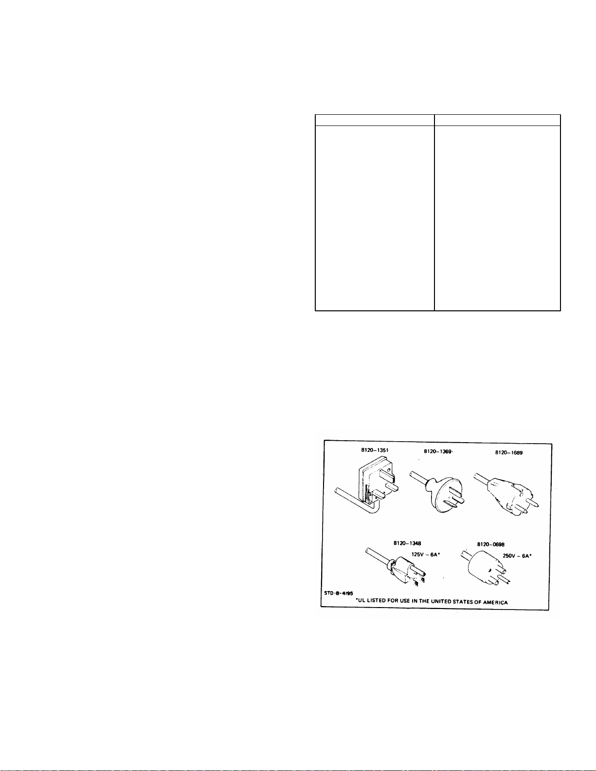
2-9. Figure 2-1 illustrates the standard power plug
configurations that are used throughout the United
States and in other countries. The -hp- part number
shown directly below each plug drawing is the part
number for a 3555B power cord equipped with the
proper plug. If the appropriate power cord is not
included with the instrument, notify the nearest HewlettPackard office and a replacement cord will be provided.
Figure 2-1. Power Plugs.
2-1
Page 12

Section II Model 355B
2-12. INSTALLATION AND REMOVAL OF
BATTERY.
2-13. To install or replace a battery, turn the four 1/4
turn fasteners on the battery cover on the rear of the
case counterclockwise to remove the cover. Lift off the
cover, lift the battery out of its recess and unplug the
three-prong connector.
2-14. Reverse the above procedure when installing a
new battery.
2-15. COVER REMOVAL.
2-16. To remove the cover from the instrument,
release the two spring latches on either side of the
instrument, then lift cover. When replacing the cover,
first check the latches for released position; then place
cover in position for latching. The power cord is stored
inside the cover by wrapping it around the retainer
fastened inside the cover.
CAUTION
DO NOT FORCE COVER INTO
PLACE. THERE IS A PROJECTION
ON THE COVER WHICH TURNS THE
POWER SWITCH TO THE OFF
POSITION TO PRESERVE BATTERY
LIFE. IF THIS IS NOT BINDING, THE
COVER FITS EASILY INTO PLACE.
2-17. REPACKAGING FOR SHIPMENT.
2-18. The following is a general guide for repackaging
at instrument for shipment. If you have any questions,
contact your local Sales and Service Office. (See
Appendix for locations.)
a. Place instrument in original container if
available. If not available, one can be
purchased from your nearest -hp- Sales
and Service Office.
b. Wrap instrument in heavy paper or plastic
before placing in inner container.
c. Use plenty of packing material around all
sides of instrument.
d. Use a heavy carton or wooden box to
house the instrument and inner container
and use strong tape or metal bands to seal
the shipping container.
e. Mark shipping container with "Delicate
Instrument" or "Fragile".
2-2
Page 13

Section III Model 3555B
SECTION III
OPERATING INSTRUCTIONS
3-1. INTRODUCTION.
3-2. The Model 3555B Transmission and Noise
Measuring Set is an extremely versatile transmission and
noise measuring set which satisfies many of the
requirements in testing telecommunications equipment.
The 3555B features a choice of 900 or 600 ohms bridging
or terminated for voice frequencies and 600, 135 or 75
ohms bridging or terminate for carrier frequencies. Noiseto-ground and noise Metallic may be measured with 3kHz
Flat, C-Message or 1 5kHz Flat weighting. A HOLD
function permits seizing the line while measurements are
being made at voice and program frequencies. The set is
portable and operates from the internal battery, office
battery or ac power source.
3-3. This section of the manual contains all the
information necessary in the operation of the 3555B along
with a description of all controls, connectors and
indicators.
3-4. CONTROLS, CONNECTORS AND
INDICATORS.
3-5. Figure 3-1, 3-2 and Table 3-1 illustrate and
describe the function of all front and side panel controls,
indicators and connectors.
3-6. OPERATION.
3-7. To operate the Model 3555B, refer to figure 3-1
and perform the following steps:
a. Before connecting the 3555B to an ac power
source, insure that the 115/230 volt switch is
positioned to indicate the line voltage to be
used. Some earlier instruments did not have
the 115/230 volt selector switch. To change
these instruments, jumper wires must be
changed on the power transformer. Refer to
Appendix C for a wiring diagram of the two
configurations.
b. If the set is to be operated from the internal
battery or from an external office battery,
place the AC/BAT switch (located on the side
of the set) to the BAT position, using a small
pointed object; if the set is to be operated
from the ac line, place the AC/BAT switch to
the AC position. For operation from a 24 or
48V office battery, connect a patch cord with
a Western Electric 310 plug to the battery
jack on the side of the case and then connect
the cord to the office battery on the test
board or bay. Inserting the plug disconnects
the internal battery. The office battery is
arranged for -48V or -24V ±2V with the
negative terminal of the battery connected to
the tip and the ground terminal connected to
the sleeve. Current consumption by the
3555B is approximately 15mA.
WARNING
DURING BATTERY OPERATION, THE
"G" BINDING POST MUST BE
CONNECTED TO EARTH GROUND.
CAUTION
THE CORD MUST BE CONNECTED TO
THE MEASURING SET BATTERY
JACK FIRST AND THEN PLUGGED
INTO THE BATTERY SUPPLY TO
AVOID SHORTING THE OFFICE
BATTERY TO GROUND.
c. Turn the POWER switch to ON and depress
the DIAL/BAT pushbutton on the FUNCTION
switch. The meter pointer should indicate in
the BAT GOOD area indicating that the
battery condition is good if the set is being
operated from the internal battery. The
meter will also monitor the ac supply voltage
or the external office battery voltage,
providing an indication of low voltage should
it exist. The voltage should cause meter
deflection above the lower end of the green
BAT GOOD area for proper set operation.
3-8. BATTERY.
3-9. The internal dry cell battery has a voltage range
between 45 volts when new to 24 volts at cut-off which is
the end of useful life. The cut-off voltage corresponds to
the left end of the green BAT GOOD area on the meter.
The condition of the battery and the approximate time to
cut-off can be estimated by observing the position of the
meter pointer in the BAT GOOD area.
3-10. The internal battery is of the carbon-zinc type with
its attendant limitations due to temperature. The service
obtained from carbon-zinc batteries depends on factors
such as current drain, discharge temperature, discharge
time and storage prior to use. The battery supplied with
the 3555B should provide in excess of 180 hours of
operation based on a 4 hours/day duty cycle at 77° F (25°
C). At other temperatures this time will change. At
temperatures above 131° F (55° C) the batteries may fail
suddenly while at temperatures below 40° F (-20° C), the
service life will be short.
3-1
Page 14
Section III Model 3555B
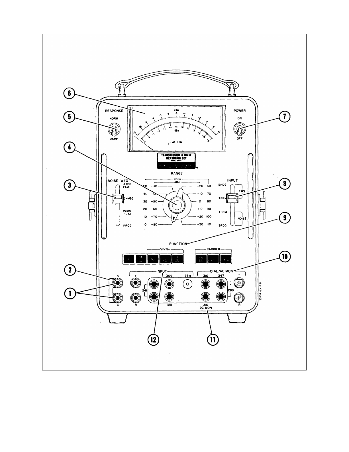
Figure 3-1. Front Panel Controls, Indicators, and Connectors
3-2
Page 15

Model 3555B Section III
Table 3-1. Front, Side and Rear Pane
(1) S and G Jacks: Binding posts accepting banana
plugs, spade lugs, phone tips or bare wires for
connection to the case ground (G) and sleeves (S)
of all INPUT jacks (12) and DIAL/AC MON jacks
(10) and (11).
(2) Shorting Strap: A swing-away shorting strap
connecting the S and G terminals together which
may be used to isolate the jack sleeves from case
ground. Not for use with type 347 plugs.
(3) WTG Switch: Selects weighting filters for noise
measurements. These filters are selectable only
when the INPUT switch is in one of the two NOISE
positions. The 3kHz FLAT, C-MSG, 15kHz FLAT
and PROG filters all conform to the standards set
up by the Bell System and Edison Institute for
measuring message circuit noise.
(4) RANGE SWITCH: Selects dBm or dBm ranges of
input sensitivity. The RANGE switch markings
correspond to the 0 markings on the meter scale
(6). The black markings are dBm for transmission
measurements and the blue markings are dBrn for
noise measurements.
(5) RESPONSE Switch: Selects NORM meter
response for transmission level measurements or
DAMP for noise measurements where noise is
impulsive in nature.
(6) Meter: A taut band individually calibrated meter
with shaped pole pieces to provide a linear dBm
indication with equal accuracy and resolution over
the entire meter scale. The dBm scale is marked
in black and has 0.1dB resolution for transmission
measurements. The 0 marking at the right end of
the scale corresponds to the black RANGE switch
setting. The dBm scale is marked in blue for noise
measurements. The 0 marking at the left end of
the scale corresponds to the blue RANGE switch
setting. The green arc marked BAT GOOD
corresponds to the green DIAL BAT pushbutton for
checking the power source. The left edge of the
arc corresponds to the battery cut-off voltage of 24
volts and the right edge (meter full-scale)
represents 60 volts which is the maximum voltage
that can be used to power the set without internal
damage.
(7) POWER ON/OFF Switch: turns on all power to the
set. The set operates from either 115 volts or 230
volts ac, the internal 45 volt dry cell battery or from
an external office battery supply.
(8) INPUT Switch: Selects TMS, either BRDG or
TERM for transmission measurements and NOISE,
either BRDG or TERM for noise measurements.
For noise measurements the switch must be in
Controls, Indicators and Connectors either the
NOISE BRDG or the NOISE TERM before the
NOISE WTG filters can be selected.
(9) FUNCTION Switch: A series of interlocking
pushbutton switches (with the exception of the
HOLD switch which is push-push type) with the
following functions:
a. VF/Nm
1. HOLD: Applies a dc holding bridge
across the metallic line for the NG, 900
and 600 functions. The HOLD
pushbutton is the push-push type, ie,
push to make and push to break. The
HOLD function cannot be
accomplished when any one of the
CARRIER pushbuttons is depressed.
2. DIAL/BAT: Connects the multiple
INPUT jacks in parallel with the
DIAL/AC MON jacks for the dial and
talk operation. The circuit is arranged
for loop dialing and the line under test
must supply talk battery. Connects the
meter circuit and a load to the internal
power supply to check the condition of
the battery, ac power or external office
battery as indicated on the green meter
scale. POWER (7) must be ON for the
battery test.
3. NG: Selects the noise-to-ground input
circuits for measuring longitudinal
noise. Attenuation of 40dB is inserted
by this circuit. Earth ground should be
connected to the black G binding post
(1)
4. 900: Selects the input circuitry for
balanced 900 ohm circuits. This
function selects a low frequency
transformer for voice frequencies.
Response of this transformer is 20Hz
to 20kHz.
5. 600: Selects the input circuitry for
balanced 600 ohm circuits. A low
frequency transformer is selected for
this function.
b. Carrier
1. 600: Selects the input circuitry for
balanced 600 ohm circuits. A high
frequency transformer is selected for
this function. Response of this
transformer is 1kHz to 600kHz. The
HOLD function is not operative in any
of the carrier functions.
3-3
Page 16
Section III Model 3555B
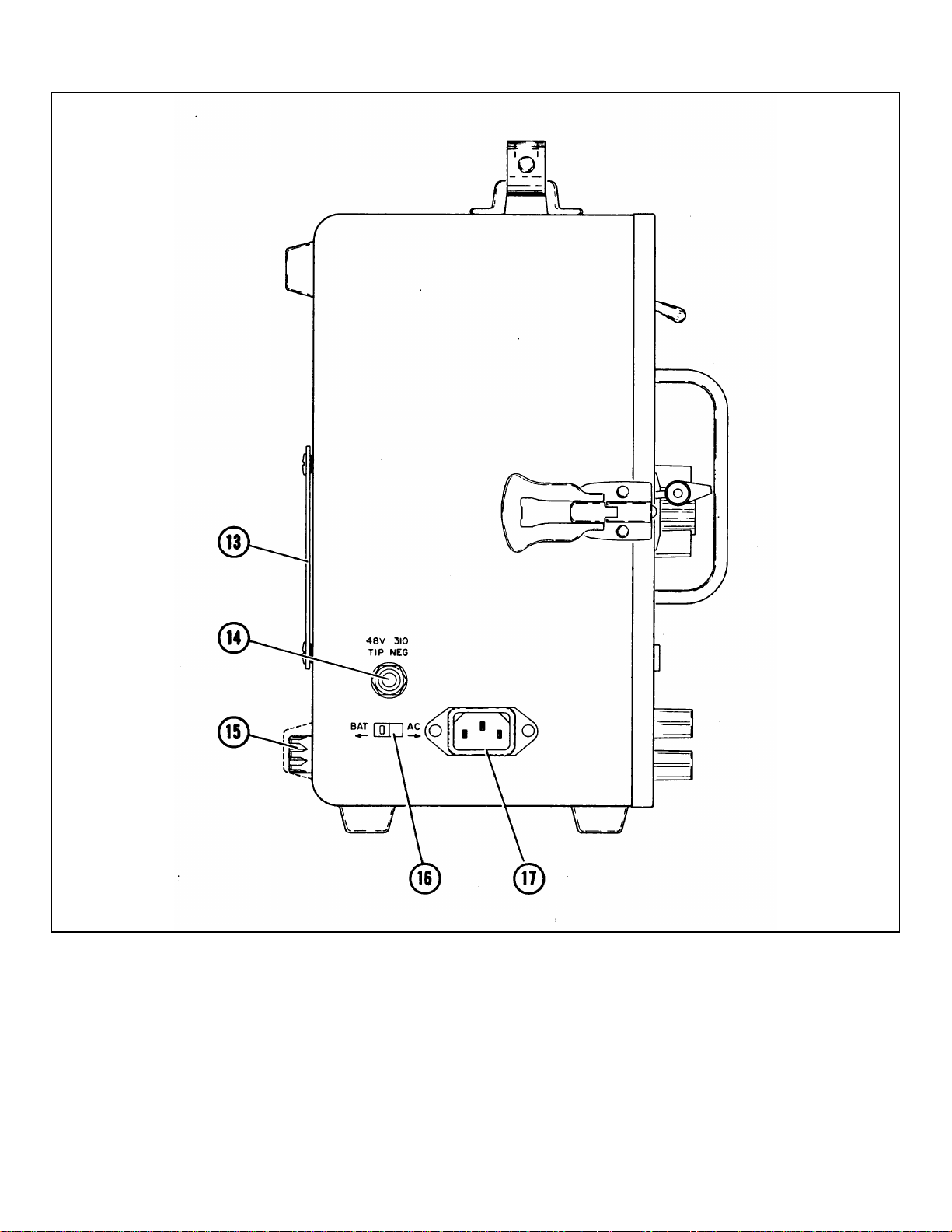
Figure 3-2. Side Panel Controls and Connectors
3-4
Page 17

Model 3555B Section III
Table 3-1. Front, Side and Rear Panel Controls, Indicators and Connectors (Cont’d)
2. 135: Selects the input circuitry for 135
ohm balanced circuits. A high
frequency transformer is selected for
this function.
3. 75: Selects the input circuitry for 75
ohm unbalanced operation. Only the
75 ohm jack can be used for this
function. This function does not utilize
an input transformer, therefore the
maximum bandwidth is available on
this function. This jack accepts a 358
plug.
(10) DIAL/AC MON: A set of multiple jacks accepting
Western Electric type 310 or 347 plugs, 289 dual
plugs and a pair of special clip posts marked T and
R which accept a Western Electric 1011IB
lineman's handset for the dial and talk operation
when the FUNCTION pushbutton marked
DIAL/BAT is depressed. Loop dialing is used and
the circuit must supply talk battery. When any
other FUNCTION pushbutton is depressed, the tip
and ring of these jacks are connected to the AC
MON output of the internal amplifiers for
monitoring purposes.
(11) DC MON: Accepts a Western Electric 310 or 347
plug for tip negative and sleeve connections to an
external dc recorder. Output voltage is
proportional to the input voltage on any one setting
of the RANGE switch.
(12) INPUT: A set of multiple jacks accepting Western
Electric 241 (or 289), 309, 310 and 358 plugs and a
pair of binding posts marked T and R for banana
plugs, spade lugs, phone tips or bare wires
providing connection to the input circuitry of the
measuring set. When the DIAL BAT pushbutton is
depressed, the INPUT jacks are connected in
parallel with the DIAL/AC MON jacks.
(13) Battery Cover: Removeable by four 1/4 turn screw
fasteners to expose the internal battery for
replacement.
(14) 48V 310: A jack accepting a Western Electric 310
plug with tip negative and sleeve ground to supply
external office battery power to the set. Insertion
of a 310 plug into this jack disconnects the internal
battery. The BAT-AC switch (16) must be set to
BAT for office battery operation.
CAUTION
WHEN OPERATING FROM AN EXTERNAL
BATTERY, CORD SHOULD BE CONNECTED
TO MEASURING SET FIRST, THEN PLUG
INTO BATTERY SUPPLY TO AVOID
SHORTING THE OFFICE BATTERY.
(15) 0.15A-SPARE Fuse: A 0.15A slo-blo fuse and a
spare for measuring set protection when operating
from AC power. Fuses are not used when the set
is battery powered.
(16) BAT-AC Switch: A slide switch for selecting the ac
power source or the internal battery and office
battery jack, (14), power source. The switch may
be operated by a small screwdriver or pointed tool
inserted into the slot in the switch.
(17) AC Power Receptacle: A 3 prong power receptacle
for the special power cord stored inside the front
cover. The BAT-AC switch (16), must be
positioned to AC for this power source.
3-11. High storage temperature is damaging to dry
cells and tends to reduce shelf life. Low storage
temperature is beneficial to battery life although the
battery should be warmed to room temperature prior to
use. Turning off the set when not in use and
consideration of the above factors will maximize battery
life. The instant turn characteristics of this set with no
warm-up time required allows turning off between
measurements.
NOTE
If the battery voltage indication drops below
the left end of the arc on the meter face the
set will not operate properly. This will be
noted by a slow oscillation of the meter. If
this symptom is encountered, depress the
DIAL/BAT pushbutton and check the battery
condition. If the indication is to the left of
the arc on the meter face, replace the
battery.
3-12. LEVEL AND NOISE MEASUREMENTS.
3-13. Since the 3555B is both a level measuring set
and a noise measuring set, the procedure for making
these measurements will be treated separately. Level
measurements can be made at voice frequencies and
carrier frequencies. Since the procedure for making
voice and Carrier level measurements are identical
except for the FUNCTION pushbutton utilized, only one
procedure will be described in detail.
3-14. LEVEL MEASUREMENTS.
3-15. The 3555B can be used as a wide range and
wide
3-5
Page 18

Section III Model 3555B
frequency Transmission Measuring Set (TMS) for voice,
program and carrier multiplex measurements. The set will
operate over a wide range of environmental conditions and
maintain a high degree of accuracy.
3-16. In general, transmission level measurements are
made by connecting the circuit under test to the INPUT
jacks with a suitable patch cord, selecting the proper
bridging or terminate condition and impedance, and then
operating the RANGE switch to provide an on-scale meter
indication. Transmission level measurements are made
with the INPUT switch in TMS position either bridging or
terminated. In this position, the set has its maximum
frequency range.
3-17. The multiple INPUT jacks and binding posts
accept the Western Electric 309, 310 and 358 single plugs
and the 241 or 289 twin plug. The two red binding posts
marked T (tip) and R (ring) will accept banana plugs,
spade lugs, phone tips or bare wires. These jacks and
binding posts are all connected in parallel and only one
should be used at a time. A patching cord such as the
Western Electric 3P12H, consisting of a cord with a 310
plug on one end and a 309 plug on the other end, should
be kept with the instrument as a universal patch cord. The
75 ohm jack accepts Western Electric type 358 plugs for
75 ohms. unbalanced carrier measurements.
3-18. The sleeves of all the INPUT and DIAL jacks are
connected together and to the black binding post marked
S. The binding post in turn, is connected through a swingaway shorting strap to a second black binding post marked
G. This binding post is the measuring set case ground.
When it is necessary to establish a battery or ground
connection on the sleeve for PBX test purposes, this
shorting strap may be disconnected by loosening the black
binding posts and swinging away the strap. A cord is then
connected to the S terminal and may be connected to the
battery or ground for the test. Type 347 plugs must not be
used when the shorting strap is removed.
3-19. The multiple jacks marked DIAL/AC MON are
connected in parallel and accept a 310 or a 347 single plug
or a 289 dual plug. A dial with the impulse springs
connected to the tip and ring of a 310 or 347 plug may be
used or a lineman's handset such as the Western Electric
1011 B may be connected to the two square clip posts for
the dialing and talk operation. When the FUNCTION
pushbutton marked DIAL/BAT is depressed, the DIAL
jacks are connected to the INPUT jacks and a number may
be dialed on the line connected to the INPUT jacks. The
circuit is arranged for loop dial operation and the circuit
under test must supply talk battery.
3-20. Once the switching equipment has been seized by
the dialing operation, the connection can be held by
depressing the HOLD pushbutton. This places a dc bridge
consisting of a high impedance retardation coil, across the
INPUT terminals. This coil has negligible effect on
measurements of voice frequencies. Once any other
pushbutton is depressed, the AC output of the internal
amplifier circuit is returned to the DIAL/AC MON jacks for
an external head Model 3555B phone which can be used
to monitor the noise or tones being measured. The
lineman's hand set which was used for the dialing
operation can be used for monitering by leaving it
connected to the clip posts. The jacks marked 310 will
accept a head phone or recorder connected to the tip and
ring of a 310 plug or tip and sleeve of a 347 plug. The
performance of the set is not affected by this output and
any impedance head-phone may be used.
3-21. The DIAL/BAT function also checks the power
source used. The green arc on the meter marked BAT
GOOD corresponding to the green BAT marking on the
pushbutton, indicates the range of voltages for proper
operation. Full scale corresponds to 60 volts and the left
end of the arc corresponds to the battery cut-off voltage of
24 volts. Thus the remaining battery life can be estimated
by noting the position of the pointer in the green arc.
Since the set POWER must be turned ON to perform this
check, the battery is properly loaded to give a true
indication of its condition. When operating from the
external office battery or AC power, the meter monitors
this voltage to indicate if it is the correct level to properly
power the set. The POWER switch turns OFF and ON all
power to the set.
3-22. The remaining FUNCTIONS are used to set up the
input conditions. The Ng function will be discussed under
the paragraph heading, "NOISE MEASUREMENTS". The
impedance of the set is selected by the pushbuttons
marked 900 and 600 for voice frequencies and 600, 135
and 75 for carrier frequencies. The 900 and 600 ohm
impedances are normally used for loop plant testing while
600, 135 and 75 ohms are usually reserved for carrier
system measurements. A bridged or terminated condition
is determined by the position of the INPUT switch. Using
this procedure, the meter will always indicate in dBm for
the impedance selected, bridging or terminated. The
terminations, when used, are provided with a dc blocking
capacitor. Accidental application of carrier or telegraph
battery, office battery or ringing voltage will not damage
the set. The pushbutton marked HOLD bypasses the
INPUT switch and terminates the circuit in addition to
placing the holding bridge across the line that is connected
to the INPUT. When the INPUT switch is in either of the
NOISE positions, weighting filters can be selected by the
NOISE WTG switch for noise measurements.
3-23. The RANGE switch selects the dBm range of the
meter. To avoid overloading the set, turn the RANGE
switch to +30dBm when connecting a circuit for testing.
Once the circuit connection is established turn the RANGE
switch counterclockwise until an on-scale indication is
obtained. The black dBm marking on the RANGE switch
identifies the input level required to deflect the meter to
the 0 mark on the black scale. The meter uses shaped
pole pieces to present linear dBm markings on the scale
with marks at 0.1 dBm increments. The accuracy and
resolution of this type of meter is the same at any point on
the scale and it is not necessary to keep the pointer in the
upper portion of the scale for maximum accuracy. The
accuracy of the set is not affected by the position of the
set. This type of meter will have the pointer off-scale to
the left
3-6
Page 19

Model 3555B Section III
when no input signal is present and a mechanical zero
adjust is not required. The actual input level to the set is
the algebraic sum of the black dBm meter scale and black
RANGE setting. For example, RANGE is set to 40dBm
and the meter indicates -6.3dBm. The input level is then (-
40) + (-6.3) = -46.3dBm. If the RANGE switch is at
+20dBm and the meter indication is 4.7dBm, the level is
(+20) + (4.7) = +15.3dBm.
3-24. All panel markings corresponding to the proper
dBm markings on the RANGE switch and meter face are in
black, as is the TMS position of the INPUT switch. The
blue markings correspond to the settings for noise
measurements as discussed in paragraph 3-28. The
response of the meter rectifier circuit is RMS which allows
the set to measure the true power of any arbitrary input
waveform provided the crest factor does not exceed 4:1.
Crest factor is defined as the ratio of the peak value of the
waveform to the RMS value of that waveform. In most
telephonic measurements, consideration of this crest
factor is not necessary.
3-25. The balanced input to the set is achieved through
the use of two repeat coils, one for voice frequencies from
20Hz to 20kHz and the other for carrier frequencies from
10kHz to 600kHz. The maximum high frequency range is
achieved through the use of the 75 ohm functions and the
75 ohm jack. This input bypasses both input repeat coils,
thus allowing measurements from 30Hz to 3MHz. This
high frequency range is limited to 600kHz on the +20 and
+30dBm ranges. The maximum longitudinal input voltage
is 150 volts peak between tip and ring and 200 volts rms at
60Hz between either tip or ring and ground.
3-26. The switch marked RESPONSE determines the
speed of the meter response and is usually left in the
NORM position for transmission measurements.
3-27. The jack marked DC MON accepts a Western
Electric 310 or 347 plug with connections to the tip and
sleeve. The dc voltage supplied by this jack can be used
to operate a dc potentiometric recorder requiring 1V or a
dc galvanometric recorder requiring 500uA. The dc output
is proportional to input level on any one range and not
meter deflection since the meter is logarithmically scaled.
Knowing the current required to drive the recorder full
scale and the input impedance of the recorder, enter these
numbers into the recorder compatability chart Figure 3-4 to
determine if the recorder is suitable for use with this set. If
these numbers do not fall within the compatability area,
refer to Paragraph 3-41. Connect an input voltage to the
set and adjust the RANGE switch until a near full scale
indication is observed on the meter. Connect the recorder
plug with the tip negative to the DC MON jack and adjust
the input level until the meter indicates 0dBm. Mark this
point, which should be near full scale, on the recorder
paper. Decrease the input level until the meter indicates 1dBm. Mark this point on the recorder paper. Continue
until the recorder has been calibrated for each major dBm
division on the meter. The actual input level to the set as
indicated on the recorder will be the algebraic sum of the
RANGE.
3-28. NOISE MEASUREMENT.
3-29. One of the primary functions of this set is to
measure message circuit noise, both metallic and noise-toground. The weighting filters built into this set are switch
selected and their characteristics conform to the standards
set up by the Bell System and Edison Electric Institute.
3-30. In general, noise-metallic measurements are made
by connecting the circuit under test to the INPUT jacks
with a suitable patch cord, selecting the proper bridging or
terminate condition and impedance, selecting the proper
weighting filter and operating the RANGE switch to provide
an on-scale meter indication. Noise measurements
involve many of the same operations as the level
measurements discussed in Paragraph 3-14 and only the
differences will be discussed.
3-31. Four filters are supplied for noise measurements;
C-MESSAGE and 3kHz FLAT for message circuit noise
measurement, a PROG and 15kHz FLAT for broadcast
studio-transmitter links and telephone company program
circuits. These filters are necessary to allow the
measuring set to approximate the response of the human
ear and give an indication representative of a person's
subjectiveness to noise. The frequency response of these
filters is shown in Figures 4-5 and 4-6.
3-32. Once a circuit has been connected, the RANGE
switch is adjusted until the noise fluctuations appear onscale on the meter with normal response, and a two-tothree minute observation of the pointer fluctuations is
made to establish the point at which the pointer appears
most of the time, disregarding the occasional high peaks.
For rapidly fluctuating noise such as atmospheric static or
switching noise, operate the RESPONSE switch to DAMP.
In this position of the switch, the level of the most
frequently occurring peaks should be read. Noise is
specified in dBm (decibels above reference noise) and the
type of filter used is noted, for example, dBmC meaning
C-message weighting is used.
3-33. The noise-metallic level is the algebraic sum of
the indication on the blue dBm meter scale and the blue
dBm RANGE switch setting. For example, RANGE is set
to 20dBm and the meter indicates +7dBm. The noisemetallic level is (20) + (+7) = +27dBm. The RANGE
switch marking indicates the level at the 0dBm mark on
the left end of the meter scale.
3-34. Occasionally other message circuit weightings
such as the older Bell System F1A weighting or the
International Telecommunication Union's CCITT or
psophometric weighting may be required. To convert from
C-message to F1A, subtract 6dBm from the C-message
indication. The units for F1A weighting are dBa, meaning
decibels adjusted. To convert from C-message to CCITT
or psophometric weighting, subtract 1dBm from the Cmessage level as read on the black dBm meter scale and
RANGE switch setting. This will give the noise level in
dBm which is acceptable for psophometric measurements.
3-7
Page 20
Section III Model 3555B
3-35. As an aid in identifying the source of noise, the
DIAL/AC MON jacks can be used with a monitoring
receiver to listen to the noise which will have
approximately the same quality as that heard by a
subscriber. Particular types of noise like power line
induction, switching noise, atmospheric static, crosstalk or
random noise may be identified by this listening test. To
aid in bringing up the level of the lower frequency power
line noise, the 3kHz flat weighting is used. A substantial
increase in meter indication with the 3kHz flat weighting
indicates the presence of low frequency noise and it will
also sound louder in the monitoring headphone.
3-36. In some cases recording of the noise during a
busy period is necessary. The recorder connections and
operation is discussed in Paragraph 3-27. The calibration
should be done using the dBm scale rather than the dBm
scale and it should be noted that the RESPONSE switch
also damps the recorder.
3-37. Noise-to-ground measurements are made by a
special input circuit arrangement which is used when
either the Ng or Ng HOLD pushbutton is depressed. Dial
and talk may be accomplished on the metallic circuit and
the metallic connection held by using the Ng HOLD
pushbutton. It is necessary to establish a good earth or
system ground and connect it to the black binding post
marked G. The noise-to-ground measurement is 40dB
less sensitive than the noise metallic measurement
because of the voltage divider in the input circuit. This
requires adding 40dB to the meter indication to arrive at
the correct noise-to-ground level. The level is the
algebraic sum of the blue RANGE switch setting and the
blue meter scale indication plus 40dB. For example,
RANGE is set to 20dBm and the meter indicates +3dBm.
3-40. Crosstalk measurements involve low level
measurements and part of the meter indication may be 38 Model 3555B caused by noise in addition to crosstalk.
The general technique is to measure with crosstalk and
noise present and then measure noise alone. A
correction factor must then be applied and can be found
in Table 3-2.
3-41. RECORDER COMPATIBILITY.
3-42. If an external recorder is to be used to monitor the
dc output of the 3555B, the Recorder Compatibility graph,
Figure 3-4 should be consulted to determine if your
particular recorder can be used. Recorders with input
characteristics that fall below the compatibility area can
be used provided a suitable resistor is used between the
3555B dc output and the recorder input.
3-43. To choose the value of this resistance, simply
follow the line designating the full scale current of your
recorder, horizontally until it intersects the top line in the
Recorder Compatibility graph. From this intersection
follow the vertical line to find the total impedance RT
required for full scale deflection (see Figure 3-3). The
input impedance of the recorder should be subtracted
from this value RT to determine the value of R1. For
example, assume that your particular recorder has an
input impedance of 2000 ohms with a full scale sensitivity
of 20uA. Follow the 20uA line to the right until it
intersects the top line at 48 kilohms. The value of R1 will
then be 48 kilohms -2 kilohms input impedance = 46
kilohms.
3-44. Recorders with input characteristics that fall
above the compatibility area in Figure 3-4 cannot be used
to monitor the 3555B dc output since full scale deflection
of the recorder cannot be accomplished by the 3555B.
The noise-to-ground level is 20 + (+3) +40= 63dBm.
Some telephone company operating procedures disregard
the 40dB correction factor in which case the noise-toground level would be 20 + 3 = 23dBm.
3-38. The Nm and Ng indications can be used to
compute the balance of a facility since balance is defined
as the degree of rejection of longitudinal signals. The
degree of balance in dB where the major part of noisemetallic is due to noise-to-ground, is given by the
Figure 3-3. Impedance Matching 3555B to Recorder
equation, Balance in dB = Nm - Ng. For example, if the
noise-metallic level of a circuit is +26dBm and the noiseto-ground of the same circuit is +9OdBmC, the balance in
dB is (+26) - (+90) = 64dB. In the case mentioned above
where the 40dB correction factor is neglected, the balance
in dB = (Nm) (Ng + 40).
3-39. Other general purpose uses of the 3555B are
volume and crosstalk measurements. The ballistic
characteristics of the set make it approximately correct for
VU measurements. The RANGE switch should be
adjusted until the meter pointer fluctuations are on-scale
and should be observed for the maximum of the
frequently occurring peaks, disregarding the occasional
high peaks. The meter indication in dBm is equal to VU
(volume units.)
3-45. APPLICATIONS.
3-46. Sometimes it is necessary to transmit or send a
tone on a line and then measure the received signal
coming back on the same line. Rather than change
connections back and forth between the 3555B and 236A
Oscillator when changing from SEND to RECEIVE and
thus take a chance on dropping the line, it is much more
convenient to make one set of connections and then
select SEND or RECEIVE by means or a switch. Refer to
Figure 3-5.
3-47. By utilizing the test set-up shown in Figure 3-5,
send and receive can be accomplished with a minimum
number of operations. To dial, set both function switches
to DIAL and dial the desired line on the butt-in. To send,
change the
3-8
Page 21
Model 3555B Section III
Figure 3-4. Recorder Compatibility Chart
Figure 3-5. Simplified Send/Receive Test Set-up
3-9
Page 22
Section III Model 3555B
236A FUNCTION switch to 600 HOLD or 900 HOLD,
depending on the impedance required. To receive a
tone, set the 3555B FUNCTION switch to either 600
HOLD or 900 HOLD (whichever is appropriate) and
change the 236A FUNCTION switch to DIAL. To send
again, simply change the 236A to 600 HOLD or 900
HOLD. If holding is not required or dialing is not
required, simply select the impedance and switch back
and forth on the 236A FUNCTION switch.
3-48. TRANSMISSION LOSS MEASUREMENTS.
3-49. Transmission loss is defined as the ratio of
power from a transmission line by a receiving terminal
to the power available from the sending equipment and
is dependent on three factors; power dissipated by the
dc resistance of the line, power losses because of
impedance mismatch, power transferred to other circuits
by inductive or capacitive coupling. (See Figure 3-6).
3-50. These factors are difficult to measure
separately. Their sum, however, is relatively easy to
measure with the -hp- 236A/3555B combination.
3-51. Figure 3-6 shows a typical transmission loss
measurement setup. The oscillator is adjusted for a
reference level and the signal is measured at the other
end of the line with a level meter. Loss measurements
are usually made at various frequencies to determine
the response of the line.
3-52. Ideally the man at each end of the line will have
both an oscillator and a Transmission Measuring Set
(TMS) so that the loss can be measured in both
directions, If the line that is being tested passes through
central office switching equipment, the oscillator or TMS
at the remote end is placed in the DIAL mode and the
lineman's handset connected to the DIAL posts,
permitting the repairman to bypass the instrument
circuitry and dial his test board at the central office.
Tests are then made in the 600 or 900 ohm HOLD
positions, which provide a dc path to hold the switching
relays.
3-53. CROSSTALK MEASUREMENTS.
3-54. Crosstalk is interference on a transmission line
caused by inductive and capacitive coupling between
pairs of transmission lines in close proximity. Crosstalk
can be classified as near-end and far-end. Far-end
crosstalk is interference at the end of the transmission
line opposite the , signal source while near-end crosstalk
is interference detected at the same end of the line as
the signal source.
Table 3-2. Crosstalk Correction Factor
dB Correction Factor
(Crosstalk + Noise) in dB Crosstalk in dB =
Minus Noise Alone in dB (Crosstalk + Noise)
Minus Correction Factor
1 7
2 4
3 3
4 to5 2
6 to 8 1
9 and above 0
3-55. Since different frequency bands are used for
each direction of transmission on two wire carrier
systems, near-end crosstalk cannot be detected. The
situation is quite different, however, for far-end crosstalk
since it is in the same frequency band as the desired
signal and can be detected.
3-56. Referring to Figure 3-7, one line is designated
A-B and the other designated C-D with A and C
representing the near-end of one of the pairs, and band
D representing the far-end of the other pair. First
measure the transmission loss between A and B. Then
measure the transmission loss from A to D. The
crosstalk coupling loss in dBx is the difference in the
reading from A to B and the reading from Ato D.
3-57. IDENTIFYING NOISE CHARACTERISTICS.
Figure 3-6. Typical Test Setup for Measuring Insertion Loss
3-10
Page 23
Model 3555B Section III
Figure 3-7. Test Setup for Measuring Crosstalk Coupling Loss
3-58. Normally, a frequency selective voltmeter is
used to identify the characteristics of transmission line
interference in order to trace it down to its origin and
apply the appropriate corrective action. As an expedient
for troubleshooting, there are several subjective
measurements that the 236A/3555B can make to help
identify the interference characteristics.
3-59. Since power line noise is the most common
nuisance, a quick check with the 3555B should be made
first. By noting the difference in noise readings between
the 3kHz FLAT and C-message weighted modes, an
indication of line frequency disturbance can be
ascertained if the 3kHz flat mode shows a substantially
higher reading.
3-60. As a further aid in identifying noise, the
lineman's handset can be connected to the AC
MONITOR terminals and an aural analysis made.
Although the handset will not respond to 60Hz, line
interference is usually very rich in odd harmonics and
180Hz can easily be identified. This test also helps to
identify "babble" and other audio frequency interference.
3-61. Vagrant noise, such as atmospheric noise, can
be analyzed by connecting a strip chart recorder to the
DC MONITOR terminals. Long-term seasonal and
temperature effects can also be measured very
conveniently with a recorder.
3-62. Frequency of strong interfering periodic signals,
such as radio transmitters, can be roughly determined
with the 236A and 3555B. The 236A is connected to
one end of the line and the 3555B to the remote end, as
with transmission loss measurements. The oscillator
output is increased until the test meter barely indicates a
signal above the noise. The oscillator frequency is then
changed very slowly while the repairman observes the
3555B for a beat. By tuning for a beat, the frequency of
oscillator frequency dial to an accuracy of approximately
±3%. In practice, this measurement would probably be
made using a "loop around" technique. The oscillator
would be connected to a quiet line at the remote location
and this line would be tied to the noisy line back at the
central office. This permits one man to operate both the
oscillator and the test meter.
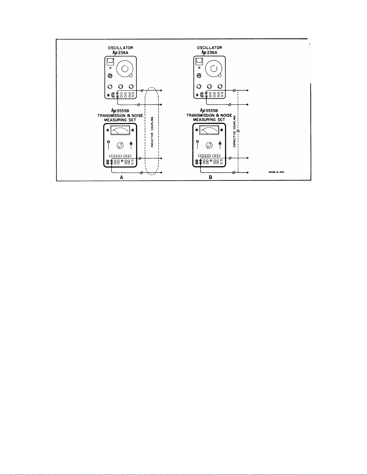
3-63. When a current flows through a conductor, it
sets up two distinct fields around the conductor - - the
electrostatic (capacitive) field and the magnetic
(inductive) field. Both are capable of inducing
longitudinal voltages in adjacent conductors, and both
increase in proportion to the power and frequency of the
current from which they result. They differ greatly,
however, in how they affect nearby circuits. The voltage
resulting from magnetic induction varies inversely-with
the impedance of the line. That is, the higher the line
impedance, the less voltage that can be induced by a
magnetic field. Capacitively coupled voltage, on the
other hand, increases in direct proportion to line
impedance-- the higher the impedance, the greater the
capacitive coupling. By means of a simple test, it is
possible to identify the coupling between two lines, as
shown in Figure 3-8. Since induced voltages are
inversely proportional to line impedance, the voltage
coupled from pair A into pair B (Figure 3-8a) will
increase as the impedance is lowered (i.e., shorted).
Conversely, since capacitively coupled voltages are
directly proportional to impedance, the coupled voltage
in Figure 3-8b would increase as the impedance is
increased (i.e., open circuited). Both tests in Figure 3-8
should be performed to correlate the result.
3-64. MEASUREMENTS IN DBC.
3-65. The term dBC means dB Collins and is defined
as
the interfering signal can be read directly off the
3-11
Page 24
Section III Model 3555B
Figure 3-8. Simple Test for Inductive and Capacitive Coupling
0dBC = 0.775V across any impedance as read on an
-hp- Model 400D AC Vacuum Tube Voltmeter. Thus,
the dBC is strictly a relative term.
3-66. Measurements can easily be made in dBC. by
utilizing the Model 3555B Telephone Test Meter. To
make these measurements, set FUNCTION to 600 and
the INPUT switch to TMS BRDG. Any termination
required other than 600 ohms must be provided
externally and connected across the two binding posts T
and R. Termination can also be made using a patch
cord and any one of the other INPUT jacks since all
INPUT jacks are connected in parallel. If a 600 ohm
termination is to be used, the internal termination can be
utilized by placing the INPUT switch to the TMS TERM
position.
3-67. MEASUREMENT PROCEDURES.
3-68. Tables 3-3 through 3-8 list the step by step
procedures for measuring levels and noise balance,
recorder calibration and transmission loss using the
3555B. For a more detailed discussion on level and
noise measurements refer to paragraphs 3-12 through
3-47.
3-69. 150 BAL CONVERSION.
3-70. The 3555B comes equipped with all the
necessary parts for converting the 135 BAL function to a
150 BAL function. The following is a simplified
procedure for making the modification.
a. Remove the set from the case and remove
the FUNCTION board. Clip the shorting
wire from across A1R17 (see Figure 7-2)
and reinstall the FUNCTION board. Leave
the set out of the case.
b. Set the 3555B controls as follows:
RANGE..........................................0dBm
FUNCTION................................135 BAL
INPUT ..................................TMS TERM
c. Remove the 150 BAL decal from the
envelope supplied with the set. Remove
the backing from the decal and place it
over the 135 BAL function pushbutton.
d. Connect a 150 ohm balanced source to the
input of the 3555B at a level of 0dBm
(387mV rms) at a frequency of 1kHz. Turn
the 3555B ON and adjust A3R24 (Figure 7-
3) for 0dBm indication on the 3555B meter.
e. Reinstall the set in its case.
3-12
Page 25
Model 3555B Section III
Table 3-3. Level Measurement
STEP PROCEDURE
1. Turn the 3555B/ON and depress the
DIAL/BAT pushbutton. The meter should
indicate in the green BAT GOOD area. If it
does not, replace the battery or check the
power source before attempting to make any
measurements. The battery test operates for
internal battery, office battery or ac power
source.
2. Select either TMS BRDG or TMS TERM,
depending on the measurement being made.
The weighting filters are not in the circuit at
this time.
3. Select the impedance (FUNCTION
pushbutton) to match the circuit to be tested.
Select either 900 BAL or 600 BAL (VF/Nm) for
frequencies between 20Hz and 20kHz. Select
600 BAL or 135 BAL (CARRIER) for balanced
measurements between 1 kHz and 600kHz.
Select 75 UNBAL for 75 ohm unbalanced
measurements between 30Hz and 3MHz.
4. Set the RANGE switch to +30dBm. Set the
RESPONSE switch to DAMP.
5. Connect the set to the line using a suitable
patch cord. For balanced measurements use
a cord having a 309 or 310 single plug, a 241
dual plug or banana plugs, bare wires or clip
leads. For unbalanced carrier measurements
(75 ohm only) use a cord having a 358 plug.
NOTE
Carrier measurements are
limited to the -50dBm RANGE
thru the +10dBm RANGE.
6. Down range the RANGE switch for an onscale indication. Level is equal to the
algebraic sum of the black RANGE setting
plus the black meter scale indication.
Table 3-4. Noise Metallic Measurements
STEP PROCEDURE
1. Turn the POWER switch to ON and depress
the DIAL/BAT pushbutton. The meter should
indicate in the green BAT GOOD area. If it
does not replace the battery or check the
power source. The battery test operates on
internal battery, office battery or ac power
source.
2. Select either NOISE TERM or NOISE BRDG,
depending on the measurement being made.
3. Select the impedance to match the circuit to
be tested using the FUNCTION pushbuttons.
The 900 BAL VF/Nm pushbuttons only should
be used for noise metallic measurements in
the frequency range of 20Hz to 20kHz. The
HOLD function can be used in NOISE TERM
if desired.
4. Select the appropriate weighting filters using
the NOISE WTG switch.
5. Set the RANGE switch to 110dBrn.
6. Connect the set to the circuit to be tested
using a suitable patch cord and down range
for an on-scale indication.
7. Observe the meter fluctuations for two or
three minutes and take a reading where the
meter pointer appears to be most of the time,
disregarding any occasional peaks.
NOTE
For rapidly fluctuating noises
such as atmospheric noise or
switching noise, operate the
RESPONSE switch to DAMP
and read the level of the most
frequently occurring peaks.
8. Noise level is equal to the sum of the blue
RANGE switch setting in dBrn and the
indication on the blue meter scale in dBrn.
EXAMPLES:
RANGE = -50dBm
METER = +1dBm
LEVEL = -49dBm
RANGE = +20dBm
METER = -4dBm
LEVEL = +16dBm
EXAMPLE:
RANGE = 40dBrn
METER = +5dBrn
NOISE LEVEL = +45dBrn
3-13
Page 26

Section III Model 3555B
Table 3-5. Noise-to-Ground Measurements
STEP PROCEDURE
1. Turn the 3555B POWER switch to ON and
depress the DIAL/BAT pushbutton. The meter
should indicate in the green BAT GOOD area.
If it does not replace the battery or check the
power source. The battery test operates for
internal battery, office battery or ac power
source.
2. Set the INPUT switch to NOISE BRDG.
3. Select the appropriate weighting filter using
the NOISE WTG switch.
4. Set the RANGE switch to 110dBrn.
5. Depress the NG pushbutton and connect the
set to the circuit to be tested. Down range for
an on-scale indication.
NOTE
Dial and talk may be
accomplished on the metallic
circuit and the connection
held by depressing the HOLD
pushbutton.
Table 3-6. Balance Measurement
STEP PROCEDURE
1. Perform the Noise-to-ground measurement as
described in Table 3-5.
2. Perform the Noise Metallic measurements as
described in Table 3-4.
3. Compute the line balance in dB using the
results of the above checks.
Balance (dB) = Nm - NG
EXAMPLE:
Noise-to-ground = +26dBrn
Noise Metallic = (-)+90dBrn
Balance in dB = -64dBm
NOTE
The noise-to-ground
measurement above includes
the 40dB correction factor.
Table 3-7. Recorder Calibration
STEP PROCEDURE
1. Determine the input impedance and full scale
sensitivity of your recorder and refer to
paragraph 3-41 and Figure 3-4 to determine if
your recorder is suitable for use with this set.
The dc voltage supplied by the DC MON 310
jack will drive a dc potentiometric recorder
requiring 1V or a dc galvanometric recorder
requiring 500uA.
2. Connect an input voltage to the set and adjust
the RANGE switch until a near full-scale
indication is observed on the meter.
3. Connect the recorder plug with the tip
negative, to the DC MON jack and adjust the
input level until the meter indicates 0dBm.
Mark this point on the recorder paper which
should be near full scale.
4. Decrease the input level to the set until the'
meter indicates -1dBm. Mark this point on the
recorder paper. Continue this procedure until
every major dBm division on the meter has
been calibrated on the recorder paper.
5. The actual level to the set as indicated on the
recorder is equal to the algebraic sum of the
RANGE setting and recorder indication.
Table 3-8. Transmission Loss Measurement
STEP PROCEDURE
1. For a transmission loss measurement to be
meaningful, it should first be determined if
there are any extraneous signals present that
will affect your measurement. To do this,
connect the measuring set to the circuit and
determine if interfering signals are present.
Levels below 60dB can, in most cases, be
ignored. A butt-in can be connected to the AC
MON jacks to aid in determining the
interfering source.
2. Establish a connection like the ones shown in
Figure 3-6.
3. Adjust the oscillator output level for 0dBm.
Measure the level at the receiving end and
record this level.
4. Insertion loss is equal to the difference
between the sending level and the receiving
level, ignoring any extraneous signals.
EXAMPLE:
Sending level = 0dBm
Receiving level = (-)- 20dBm
Insertion loss = 20dB
3-14
Page 27

Model 3555B Section IV
SECTION IV
THEORY OF OPERATION
4-1. INTRODUCTION.
4-2. The Model 3555B Transmission and Noise
Measuring Set is a special measuring set designed for
uses in testing telecommunications equipment. Inputs
between -90dBm and +30dBm full scale can be selected
in twelve ranges for level measurements and
correspond to the black markings on the meter scale
and the RANGE switch. Noise measurements between
0dBrn and +120dBrn full scale can be made, selectable
in twelve ranges and corresponds to the blue markings
on the meter scale and RANGE switch. When
measuring rapidly fluctuating noises, a damping circuit
can be inserted by the RESPONSE switch.
4-3. Impedances of 75, 135 and 600 ohms,
terminated or bridging can be selected for carrier level
measurements. The 135 and 600 ohm functions can be
either balanced or unbalanced while the 75 ohm
function is unbalanced only. For voice frequencies,
impedances of 600 and 900 ohms are provided. These
impedances are selectable by the pushbutton
FUNCTION switch and can be terminated or bridging,
balanced or unbalanced.
4-4. A noise-to-ground (Ng) function is included to
permit measurement of longitudinal noise. When the
Ng pushbutton is depressed, a 40dB attenuator is placed
across the INPUT terminals.
4-5. The HOLD function places a high inductance
holding coil across the INPUT terminals to simulate an
off-hook condition while measurements are being made.
The HOLD function is not operative on any of the carrier
functions.
4-6. A variety of INPUT and DIAL jacks are provided
which accept Western Electric type 241 and 289 dual
plugs, 309, 310, 347, and 358 single plugs, dual banana
plugs, clip leads and bare wires.
4-7. BLOCK DIAGRAM DESCRIPTION.
4-8. Figure 4-1 illustrates a simplified block diagram
Set. Refer to this figure for the following block diagram
description.
4-9. The input signal is first applied to the
FUNCTION switch where the input circuitry is set up to
accommodate the type of measurement being made.
For voice frequencies, impedances of 900 ohms or 600
ohms can be selected, bridged or terminated. Voice
frequencies are then applied to a transformer with a
frequency range of 20Hz to 20kHz. The HOLD function
places a high inductance bridge across the INPUT
terminals to simulate an off-hook condition. For carrier
frequencies impedances of 600 ohms, and 135 ohms
can be selected, terminated or bridged, balanced or
unbalanced. Carrier frequencies at these impedances
are applied to a transformer having a frequency range
from 5kHz to 600kHz. For 75 ohm carrier frequencies
an unbalanced input is provided. This input can be
either terminated or bridged. HOLD is not possible on
any of the carrier functions.
4-10. For longitudinal measurements, an Ng function
is provided which places a 40dB attenuator across the
INPUT terminals. The HOLD function bridges the input
with a holding coil while measurements are being made.
The output of the 40dB attenuator is always applied to
the voice frequency transformer.
4-11. The DIAL/BAT function serves two functions.
First it connects the DIAL/AC MON jacks to the INPUT
jacks so that a handset can be used for dialing.
Secondly, the meter is connected to the unregulated
power supply so that the battery condition can be
monitored.
4-12.After the signal is conditioned by the input circuitry
it is coupled to the RANGE attenuator where the signal
level is adjusted to provide the proper input for the Input
Amplifier. The RANGE attenuator provides from 0dB to
80dB of attenuation. It also provides gain switching for
the Input Amplifier.
of the Model 3555B Transmission and Noise Measuring
Figure 4-1. Simplified Block Diagram
4-1
Page 28

Section IV Model 3555B
4-13. The output of the Input Amplifier goes to the
INPUT switch where noise filters are set up for selection
by the NOISE WTG switch. In the NOISE position,
either 3kHz FLAT weighting, C Message weighting,
15kHz FLAT weighting or PROGRAM weighting can be
selected by the NOISE WTG switch. In the TMS
position of the INPUT switch the filters are bypassed for
transmission level measurements.
4-14. The output from the INPUT switch goes to the
meter amplifier. This amplifier provides an ac signal to
the DIAL/AC MON jacks so that a handset can be used
to listen to the signal being measured. This is
particularly useful in determining noise characters.
4-15. The detector circuit provides an equivalent rms
detected voltage to drive the meter. The meter has
shaped pole pieces to provide a linear meter scale both
for dBm and dBrn.
4-16. DETAILED CIRCUIT DESCRIPTION.
4-17. The purpose of the function switch is to set up
the input conditions to match the type of measurement
being made. Impedances can be selected to match the
lines to be tested and can be either bridged or
terminated. Separate transformers are selected for
voice frequency and carrier frequency measurements.
A 40dB attenuator is bridged across the input terminals
for longitudinal noise measurements when the Ng
pushbutton is depressed. The HOLD function places a
high inductance holding coil across the input terminals
to simulate an off-hook condition. Each of these
functions is described in detail in the following
paragraphs.
a. HOLD: When the HOLD pushbutton is
depressed a high inductance coil LI is
connected across the Model 3555B
balanced INPUT terminals if the INPUT
switch is in the TERM position. A bridging
HOLD is not possible. The TERM switch
connects the two windings of L1 in series.
b. DIAL BAT: (See Figure 4-2) The DIAL BA1
pushbutton serves two purposes. First it
disconnects the meter from the detector
and connects it to the unregulated power
supply so that the battery voltage can be
monitored. Secondly, the DIAL/AC MON
jacks are disconnected from the amplifier
ac output and connected to the INPUT
jacks. This permits connecting the
lineman's handset to the balanced line for
the purpose of dialing.
c. Ng: (See Figure 4-3) The Ng pushbutton
connects a 40dB attenuator across the
balanced input terminals for longitudinal
measurements. This attenuator consists of
A1R5 thru A1R8 and A1C1. The output is
taken from the junction of AIC1 and A1R8.
This output is referenced to ground and
applied to the voice frequency transformer
A1T2.
d. 900 (Vf/Nm): The 900 function switch S4
selects terminating resistors AIRI and A1R9
for 900 ohm terminations. The INPUT
switch must be in _ the TERM position to
complete the circuit for this termination.
The 900 function switch also places a
ground on the 900 ohm relay A3K1 which
provides gain switching in the Input
Amplifier so that the meter will indicate in
dBm. The 900 ohm signal is applied to the
voice frequency transformer A1T2. HOLD
can be accomplished on this function.
Figure 4-2. Simplified DIAL BAT Function
4-2
Page 29

Model 3555B Section IV
Figure 4-3. Simplified NG Function
e. 600 (Vf/Nm): The 600 function switch S5
selects terminating resistors A1R2 and
A1R10 for a 600 ohm termination. The
INPUT switch completes the circuit for this
termination. The 600 (Vf/Nm) signal is
applied to T2. No gain switching is
performed in this function since the set is
normalized at 600 ohms HOLD can be
accomplished on this function.
f. 600 (Carrier): This function is identical to
the 600 (Vf/Nm) function except that the
signal is applied to A1T1 and HOLD cannot
be accomplished on this function.
g. 135 (Carrier): The 135 function is identical
to the 600 (carrier) function except that the
gain switching in the Input Amplifier is
accomplished by one section of the 135
function switch S7.
h. 75 UNBAL: The 75 UNBAL function
bypasses the balanced input circuitry and
transformer AlT1 and A1T2. Gain
switching is performed by one section of
this function switch. When the 75 UNBAL
function is selected the output of the
balanced circuitry is disconnected. A 75
ohm termination is provided thru the
INPUT switch.
4-18. RANGE ATTENUATOR A2.
4-19. The RANGE attenuator adjusts the input signal
to a suitable level for the Input Amplifier. This
attenuator is composed of four L pads, selectable in
combinations to provide from 0dB to 80dB of
attenuation. Two 30dB pads are selected by A2S1A and
A2S1B, a 20dB pad is selected by A2S1C and a 10dB
pad is selected by A2S1D. Another section of the
RANGE attenuator switch provides gain switching for
the Input Amplifier in the -80dBm, -70dBm and -60dBm
positions. Refer to Table 4-1 for more detailed
information on range attenuation and amplifier gain.
4-20. INPUT AMPLIFIER A3. (Schematic No. 2)
4-21. The purpose of the Input Amplifier is to provide
the necessary gain at each setting of the RANGE switch
and to provide the necessary gain at all impedances.
This amplifier is normalized at 600 ohms and the
following discussion is for the 600 ohm function.
4-22. Diodes A3CR1 thru A3CR4 serve as protection
for the input amplifier. Signals greater than 7 volts
peak-to-peak will be conducted to ground through these
diodes. The gain of this amplifier is determined by the
negative feedback from the emitter of A3Q5 to the base
of A3Q2. This feedback is first determined by the ratio
of A3R13 to the sum of A3R14 and A3R15. In position
1 of the RANGE switch (-80DBM) this feedback is
further divided by the ratio of A3R11 to the sum of
A3R25 and A3R26. In position 2 (-70DBM) of the
RANGE switch the feedback is determined by the ratio
of A3R11 to the sum of A2R13, A3R25 and A3R26. In
position 3 (-60DBM) of the switch the feedback is
determined by the ratio of A3Rll to the sum of A2R13,
A2R14, A3R25 and A3R26.
4-3
Page 30

Section IV Model 3555B
Table 4-1. Range Attenuation and Amplifier Gain
RANGE RANGE ATTENUATOR
Setting Attenuation PADS USED Input Amplifier Gain
+30dBm 80dB 1,2,3 3.6dB
+20dBm 70dB 1,2,4 3.6dB
+10dBm 60dB 1,2 3.6dB
0dBm 50dB 2,3 3.6dB
-10dBm 40dB 2,4 3.6dB
-20dBm 30dB 2 3.6dB
-30dBm 20dB 3 3.6dB
-40dBm 10dB 4 3.6dB
-50dBm 0dB 0 3.6dB
-60dBm 0dB 0 13.6dB
-70dBm 0dB 0 23.6dB
-80dBm 0dB 0 33.6dB
In positions 4 thru 12 (-SODBM thru +30DBM), A3R11 is
bypassed for maximum feedback. The gain of the
amplifier in these nine positions is a constant 2.5dB.
Potentiometer A3R26 is for calibration of the -80DBM
range, 600 ohm function. Resistor A3R27 is used to
maintain a charge on A3C22 to prevent transients when
changing ranges.
4-23. In order that the meter always indicate in DBM
regardless of the impedance selected, additional gain
switching must be performed. When the 75 function is
chosen, A3K2 energizes and places A3R16 in parallel
with A3R14 and A3R15. This reduces the negative
feedback (with respect to the 600 function) and
increases the amplifier gain by 9dB. When the 135
function is selected, A3R22/R23/R24 are connected in
series with A3R16. This combination is then in parallel
with A3R14 and A3R15, reducing the feedback and
increasing the amplifier gain by 6.4dB with respect to
the 600 function. When the 900 function is depressed,
A3R17, A3R19 and A3R20 are connected in parallel
with A3R13, increasing the negative feedback and
reducing the amplifier gain by 1.7dB. Relays A3K1 thru
A3K3 are controlled by the FUNCTION switch when any
of the impedance functions except 600 are selected.
4-24. Transistors A3Q1 and A3Q2 form a differential
amplifier. The signal is taken from the collector of
A3Q1, amplified by A3Q4 and A3Q5 with A3Q5
providing feedback to the base of A3Q2. Transistor
A3Q3 provides isolation between A3Q2 and A3Q4 to
prevent undesired feedback. This results in a greater
bandwidth than could be achieved without its use. The
output signal is coupled through A3R17 and A3C10 to
the INPUT switch.
4-25. FILTERS. (Schematic No. 3)
4-26. The 3555B contains a 3kHz FLAT weighting
filter, a C MSG weighting filter, a PROG weighting filter
and a 15kHz FLAT weighting filter. These active filters
consist of five amplifiers with controlled feedback for
waveshaping. They are used in combinations to form
each of the filters (refer to Figure 7-1). Since all of
these amplifiers are
Figure 4-4. Simplified Average Detection
4-4
Page 31

Model 3555B Section IV
Figure 4-5. 3kHz FLAT and Program Weighting Curves
4-5
Page 32

Section IV Model 3555B
Figure 4-6. C-MSG and 1SkHz FLAT Weighting Curves
4-6
Page 33

Model 3555B Section IV
identical in operation, only the first will be discussed in
detail.
4-27. Referring to Figure 7-4, the signal is applied to
the assembly through pin 22. If C MSG is selected the
signal is first attenuated by A4R1, A4R2 and A4R3A.
Potentiometer A4R3A is for C MSG level adjustment for
0dB at 1kHz. The signal is then applied to the first in a
series of amplifiers. The first amplifier consists of A4Q1
through A4Q4. Differential amplifier A4Q1 and A4Q2
amplifies the signal and applies it to A4Q3 and A4Q4.
The emitter circuit of A4Q4 provides two feedback
signals, positive feedback through A4R8 and A4C4 to
the base of A4Q1 and negative feedback to the base of
A4Q2. The gain of this amplifier is controlled by the
ratio of the value of A4R10 to the value of A4R9. For
example, increasing the value of A4R9 would increase
the negative feedback and reduce the amplifier gain.
Gain can be calculated by the equation:
A4R10
Gain = 1 + A4R9
Positive feedback to the base of A4Q1 determines the
frequency response of this amplifier and is controlled by
the value of A4C4 and A4R8. All five of the amplifiers
are used in C Message weighting.
4-28. The Program weighting filter utilizes only
amplifiers No. 2 and No. 3 as shown in Figure 7-1.
These amplifiers are identical to the one described in
the preceeding paragraph except for the value of the
positive feedback utilized for shaping and the negative
feedback used for gain control. This negative feedback
is modified by resistance in the feedback divider at the
base of A4Q12. Transistors A4Q5 and A4Q6 provide
additional gain required for Program weighting.
Potentiometer A4R3B is used for PROG level
adjustment at 1kHz.
4-29. The 3kHz FLAT and 15kHz FLAT weighting
filters utilize only amplifier as indicated in Figure 7-1.
The only difference between these two active filters is in
the positive feedback used for shaping and in the
negative feedback used for gain. The negative
feedback is altered by adding resistance to the feedback
divider at the base of A4Q12.
4-30. METER AMPLIFIER. (Schematic No. 4)
4-31. The meter amplifier consists of A3Q6 through
A3Q10. The signal is first amplified by differential
amplifier A3Q6 and A3Q7. The signal is taken from the
collector of A3Q6 and then amplified by A3Q9 and
A3Q10. Transistor A3Q8 provides isolation between
A3Q7 and A3Q9 to prevent undesired feedback. Two
signals are taken from A3Q10. The collector circuit
supplies a signal to the DIAL/AC MON jacks for the
purpose of listening to the measured signal. The emitter
circuit of A2Q10 provides a drive signal for the detector
circuit.
4-32. DETECTOR. (Schematic No. 4)
4-33. The detector is a class B rms detector which
combines the features of an average detector and a
peak detector. When the average detected signals and
the peak detected signals are combined in the proper
proportion an equivalent rms response is produced.
4-34. First consider the average detection in this
circuit. (See Figure 7-5). Transistors A3Q12-A3Q13
and A3Q15-A3Q16 are functionally symmetrical. This
means that A3Q14 and A3Q17 are driven by the same
signal. When the signal at the base of A3017 and
A3Q14 goes negative, A3Q! 4 turns on and A3Q17 turns
off. No current will flow through the meter. On the
positive half cycle A3Q14 turns off and A3Q17 turns on.
The current paths for the average detector are shown in
Figure 4-4.
Figure 4-7. Simplified Peak Detection
4-7
Page 34

Section IV Model 3555B
from either the battery or from an ac source, capacitor
4-35. Now consider the peak detection. (See Figure
7-5) When A3Q14 is turned on and A3Q17 is turned off,
no current flows through the meter from the peak
detector When A3Q14 is turned off and A3Q17 is turned
on, the current path is as shown by the heavy lines in
Figure 4-7 Diodes A3CR12 and A3CR13 are included to
offset the junction drop of A3CR15 and A3CR16
respectively.
4-36. When the average detection and the peak
detector are combined in the proper proportion, an
equivalent rms response is produced. The advantage of
this type of rms detection is fast response.
4-37. POWER SUPPLY AND SERIES REGULATOR
(Schematic No. 4)
4-38. The 3555B can be operated from 115V or 230V
ac, the internal 48V dry cell battery or from a central
office battery (tip negative). When operating from an ac
source power is applied through transformer TI and the
AC/BAT switch S1 to the rectifier CR1. This rectified
voltage is filtered by C2 before being applied to the
series regulator through J2, S3, CR1 and cable W1.
4-39. The regulator is of the conventional series type
with A3Q19 acting as the sensing element and A3CR20
as the reference. Changes in the output level are
amplified by differential amplifier A3Q18 and A3Q19.
The output of the differential amplifier is amplified by
A3Q20 and applied to A3Q21 which controls the
conduction of the series transistor A3Q22. The output
of this series regulator is held at - 20 volts ±1 volt. The
maximum ac ripple and noise on the output voltage is
200µV rms.
4-40. It should be noted that when operating the set
C2 will always be charged whether the set is turned on
or not. Caution should be exercised when servicing the
power supply.
4-8
Page 35

Model 3555B Section V
SECTION V
MAINTENANCE
5-1. INTROOUCTION.
5-2. This section of the manual contains information
necessary in the maintenance of the -hp- Model 3555B
Transmission and Noise Measuring Set. Included are
performance checks, adjustment and calibration
procedures and troubleshooting.
5-3. The test equipment needed to properly maintain
and service the Model 3555B is listed in Table 5-1.
Included in Table 5-1 is the equipment to be used,
required specifications 'and recommended model. If the
recommended model is not available other equipments
Table 5-1. Required Test Equipment
INSTRUMENT RECOMMENDED
TYPE REQUIRED CHARACTERISTICS MODEL
Oscillator Frequency Range: 20Hz to 3MHz -hp- 654A
Levels: -80dBm to +30dBm
Accuracy: ±0.1 5dB
Oscillator Frequency Range: 100Hz to 20kHz -hp- 201 C
Amplitude: 30V
Transformer Line matching -hp- 11004A
Voltmeter, Function: AC and DC -hp- 3440A/3445A
digital Accuracy: ±.1%
Amplifier Voltage gain: 20 dB -hp- 467A
Output: +/-20V peak at 0.5A peak
Voltmeter, AC Frequency Range: 20Hz-4MHz -hp- 400FL
Accuracy: ±2%
Termination 50 ohms ±.25% -hp- 11048B
Termination 75 ohms ±.25% -hp- 11094A
Cables Balanced BNC to 310 plug See Figure 5-1.
Adapter BNC to 358 plug Trompeter Electronics
Resistors 576 ohms ±1% (1) -hp- Part No. 06984598
875 ohms ±1% (1) (Use 825 ohm, 0757-0731 and
300 ohms 0.1 % (4) -hp- Part No. 0698-6295
600 ohms ±0.1% (4) -hp- Part No. 0698-7408
135 ohms ±0.1%(4) -hp- Part No. 0698-7364
75 ohms ±0.1% (4) -hp- Part No. 0698-7363
900 ohms ±0.1% Use 600 and 300 in series (0.1%)
150 ohms ±.1% (2) -hp- Part No. 0698-6774
100 kilohms 1% (1) -hp- Part No. 0757-0465
can be substituted provided they meet the required
specifications.
5-4. FACTORY SELECTED VALUES.
5-5. Factory selected values are denoted on the
schematic diagrams by an asterisk. The nominal value
is shown. The value in your instrument may be different
or the part may be omitted.
5-6. 150 BAL CONVERSION.
a. To convert the 135 BAL function to a 150
BAL
No. AD-1W
49.9 ohm, 0698A4110 in series)
5-1
Page 36

Section V Model 3555B
Figure 5-1. Balanced BNC to 310 Plug
function, remove or clip the shorting bar
from across A1 R17 (see Figure 7-2).
b. Remove the 150 BAL decal from the small
envelope supplied with the set and stick it
over the existing 135 BAL decal.
c. Adjust the 150 function as described in
Paragraph 5-20 in this manual.
5-7. PERFORMANCE CHECKS.
5-8. The performance checks presented in this
section are in-cabinet checks designed to compare the
Model 3555B with its published specifications. These
checks can be used for incoming inspection, periodic
maintenance checks and to verify performance after
adjustment or repair. A performance check test card
appears at the end of this section which can be used to
record the specification performance of your set.
5-9. LEVEL ACCURACY CHECKS.
a. Connect only the 654A and 3555B as
shown in Figure 5-2 and set the 3555B
controls as follows:
FUNCTION...........CARRIER, 75 UNBAL
INPUT .................................TMS, TERM
RANGE......................................+10dBm
b. Set the 654A frequency to 20kHz,
IMPEDANCE to 75 UNBAL and adjust the
output level for +10dBm. If the calibration
of the 654A is questionable, first connect
the output of the 654A through a 75 ohm
termination, directly to the input of the
3440A/3445A (3555B not connected) and
measure the voltage. This level should be
866mV rms. If it is not, adjust the 654A
amplitude control until it is and note the
654A meter indication for future reference.
Now that the 654A calibration has been
verified, disconnect
Figure 5-2. Level Accuracy Check
5-2
Page 37

Model 3555B Section V
and change the 201C output level for
Table 5-2. 75 UNBAL Carrier Accuracy Check
3555B INDICATION (dBm)
RANGE
FREQUENCY
30Hz to 1MHz 100Hz to 600kHz 1MHz to 3MHz
+10dBm +10 ±0.5 +10 ±0.2 +10 ±0.5 ±10% of meter indication in dBm
0dBm 0 ±0.5 0 ±0.2 0 ±0.5 ±10% of meter indication in dBm
-10dBm -10 ±0.5 -10 ±0.2 -10 +0.5 ± 0% of meter indication in dBm
-20dBm -20 ±0.5 -20 ±0.2 -20 ±0.5 ±10% of meter indication in dBm
-30dBm -30 ±0.5 -30 ±0.2 -30 ±0.5 ±10% of meter indication in dBm
-40dBm -40 ±0.5 -40 ±0.2 40 ±0.5 ±10% of meter indication in dBm
-50dBm -50 ±0.5 -50 ±0.2 -50 ±0.5 ±10% of meter indication in dBm
the 3440A/3445A and reconnect the output
of the 654A to the input of the 3555B.
Maintain the 654A meter reference
throughout the remainder of the following
checks.
c. The 3555B meter should indicate 0dBm
±0.1 dBm.
d. Check all the RANGES and frequencies
listed in Table 5-2 for the specified
tolerances. Be sure to maintain the 654A
reference established in step b.
e. Change the 654A to 600 BAL and change
the 3555B to CARRIER, 600 BAL.
Connect the 654A 600 BAL output to the
3555B input using a balanced cable.
f. Check the RANGES and frequencies in
Table 5-3, using the same procedure
described for the 75 UNBAL function.
g. Change the 654A to 135 BAL and change
the 3555B to 135 BAL. Repeat step e for
the same RANGES and tolerances
indicated for the CARRIER 600 BAL
function in Table 5.-3.
h. Change the 3555B to VF/Nm, 600 BAL and
change the 654A to 600 BAL. Check the
+10dBm thru -80dBm ranges in Table 5-4
for the tolerances indicated.
i. Change the 3555B to 900 BAL and connect
a 150 ohm ± 1% resistor in series with each
input lead. Readjust the 654A for 0dBM.
Repeat the checks in Table 5-4 for the
same tolerances.
j. To check the top two ranges, connect the
equipment as shown in Figure 5-3 and set
the 3555B controls as follows:
FUNCTION....... VF/Nm 600 BAL
INPUT .................... TMS, TERM
RANGE..........................+20dBm
k. Adjust the 201C for 7.75V on the
3440A/3445A at 100Hz.
l. Tune the 201 C from 100Hz to 20kHz,
maintaining 7.75V on the 3440A/3445A.
Between 100Hz and 15kHz, the 3555B
indication must not change more than
±0.2dBm. Between 15 kHz and 20kHz, the
indication must not change more than
±0.5dBm.
m. Check the +30dBm range using the
procedure described in Steps j through 1,
except change the 3555B range to +30dBm
24.49V.
n. To check the 900 ohm function on the
+20dBm and +30dBm ranges, connect a
300 ohm +0.1% resistor in series with the
3555B input in Figure 5-3.
o. Change the 3555B to 900 BAL and change
the range to +20dBm.
p. Adjust the 201 C output for 9.49V as
indicated on the 3440A/3445A.
q. Check for the tolerances indicated in Table
5-4 for the +20dBm range.
r. Change the 3555B range switch to +30dBm
and adjust the 201C for 30V on the
3440A/3445A. Check for the tolerances
indicated in Table 5-4 for the +30dBm
range.
Table 5-3. Carrier Level Accuracy
3555B Indication (dBm)
RANGE 135 1kHz -600kHz 10kHz - 300kHz
600 1kHz - 150kHz 10kHz - 100kHz
-50 thru +10dBm ±0.5 ±0.2*
*Increase specification by ±0.3dB on 135 ohms (or 150
ohms) when not battery powered.
5-3
Page 38

Section V Model 3555B
Figure 5-3. +20dBm and +30dBm Level Accuracy Check
5-10. RETURN LOSS CHECK.
a. To make a return loss check it will first be
necessary to construct a balanced bridge
utilizing 0.1% resistors for each of the four
3555B impedances. Figure 5-4 shows the
equipment test set-up to be used. For this
check to be meaningful, all test leads
should be kept short. The leads connecting
the 3555B to the bridge should be short clip
leads and should be kept away from each
other and from other leads. Keep all the
instruments away from other instruments
that may be referenced to earth ground.
b. Connect the equipment as shown in Figure
5-4 and set the 3555B controls as follows:
Table 5-4. VF/Nm Level Accuracy Checks 600 BAL and 900 BAL
RANGE 20Hz to 20kHz 40Hz to 15kHz 100Hz to 20kHz 100Hz to 15kHz
+30dBm +30 ±0.5 +30 ±0.2
+20dBm +20 ±0.5 +20 ±0.2
+10dBm +10 ±0.5 +10 ±0.2
0dBm 0 ±0.5 0 ±0.2
-10dBm -10 ±0.5 -10 ±0.2
-20dBm -20 ±0.5 -20 ±0.2
-30dBm -30 ±0.5 -30 ±0.2
-40dBm -40 ±0.5 40 ±0.2
-50dBm -50 ±0.5 -50 ±0.2
-60dBm -60 ±0.5 -60 ±0.2
-70dBm -70 ±0.5
-80dBm -80 ±0.5
FUNCTION..................VF/Nm, 600 BAL
INPUT................................TMS, TERM
RANGE........................................0dBm
NOTE
The 3555B does not have to be
turned on for this check. If at any
frequency the 3555B return loss
check is out of specification, check
the reference at that frequency as
described in the following
procedure.
c. Set the 654A frequency to 1kHz.
Temporarily close S1 in Figure 5-4 and
adjust the 654A output level for an up scale
indication on the 400FL AC Voltmeter.
-80dBm through +30dBm
5-4
Page 39

Model 3555B Section IV
Figure 5-4. Return Loss Test Set-Up
d. Open S1 and down range the 400FL for an
on-scale indication. This indication
subtracted from the reference established
in step c, is the bridge balance and should
be greater than the return loss
specification.
e. Unplug or disconnect R4 in Figure 5-4 and
connect the 3555B tip and ring in its place.
Be sure to use short clip leads.
f. Momentarily close S1 and recheck the
reference on the 400FL. .Open S1 in
Figure 5-4 and down range the 400FL for an
on-scale indication. This indication must
be down at least 30dB from the reference.
g. Tune the 654A from 50Hz to 20kHz. The
400FL indication must remain at least 30dB
down from the reference.
h. Change the 3555B FUNCTION to
CARRIER 600 BAL and repeat steps f and
g between 3kHz and 150kHz. Return loss
must be at least 26dB down from the
reference.
i. Change the bridge resistors in Figure 5-4 to
900 ohms f 0.1% (use 300 ohms + 0.1% in
series with 600 ohms ±0.1%) and change
the 3555B FUNCTION to VF/Nm 900 BAL.
Be sure to reset the reference level after
the resistors are changed. Check the
return loss between 50 Hz and 20 kHz.
The return loss must be better than 30 dB.
FIG 5-1
Figure 5-5. Filter Response Test Set-UP
5-5
Page 40

Section V Model 3555B
the 654A for
Figure 5-6. Bridging Loss Test Set-Up
j. Change the bridge resistors in Figure 5-4 to
135 ohms +0.1% and change the 3555B
FUNCTION to 135 BAL. Check the return
loss between 1kHz and 600kHz. The
return loss must be better than 26dB down
from the reference.
k. Change the 3555B input connection to the
75 UNBAL jack. Change the resistors in
Figure 5-4 to 75 ohms +0.1% and change
the 3555B FUNCTION to CARRIER 75
UNBAL.
l. Check the return loss between 1kHz and
3MHz. The return loss must be better than
30dB down from the reference.
5-11. FILTER RESPONSE CHECKS.
a. C MSG FILTER RESPONSE
Table 5-5. Filter Response Checks
FREQUENCY C MSG (dBm) 3kHz FLAT (dBm) 15kHz FLAT (dBm) PROGRAM (dBm)
60Hz -55.7 ±2 0 ±1.75 0 ±1.75
200Hz -25 ±2 -17.3 ±2
250Hz 0 ±1 0 ±1
500Hz -7.5 ±1 -6.6 ±1
1kHz 0(Ref) 0(Ref) 0(Ref) 0(Ref)
2kHz -1.3 ±1 -0.5 ±1.75 4.8 ±2
2.5kHz -1.4 ±1 -1.5 ±2
3kHz -3 ±3 +6.5 ±2
4kHz -14.5 ±3 +6.5 ±2
5kHz -28.5 ±3 0 ±1 +6.5 ±2
6kHz +6.4 ±3
8kHz +4 ±3
10kHz -0.5 ±1.75 -8.5 ±4
12.5kHz -1.5 ±2
15kHz -3 ±3
1. Connect the equipment as shown in
Figure 5-5 with S1 in position 1 and
set the 3555B controls as follows:
FUNCTION......... VF/Nm 600
INPUT ............NOISE BRDG
RANGE .......................0dBm
2. Adjust the output of
0dBm at a frequency of 1 kHz.
3. Check the frequencies listed in Table
5-5 for the tolerances indicated.
b. 3kHz FLAT FILTER RESPONSE
1. Set the 654A frequency to 1kHz and
adjust the output level for 0dBm.
2. Check the frequencies listed in Table
5-5 for the tolerances indicated.
c. 15kHz FLAT FILTER RESPONSE
5-6
Page 41

Model 3555B Section V
1. Reset the 654A output level for 0dBm
indication on the 3555B meter at a
frequency of 1kHz.
2. Check the frequencies listed in Table
5-5 for the tolerances indicated.
d. PROG FILTER RESPONSE
1. Reset the 654A frequency to 1kHz and
adjust the output level for 0dBm
indication on the 3555B meter.
2. Check the frequencies listed in Table
5-5 for the tolerances indicated.
5-12. BRIDGING LOSS.
a. Connect the equipment as shown in Figure
5-6 and set the 3555B controls as follows:
FUNCTION............VF/Nm 600
INPUT...................TMS BRDG
RANGE.......................... 0dBm
b. Adjust the output of the 654A (600 ohm
function) for 0dBm indication on the 400FL
at a frequency of 1kHz.
c. Connect the 3555B to the 400FL input.
The indication on the 400FL should not
drop more than 0.3dB.
d. Change the FUNCTION switch to
CARRIER 600 and repeat the above
procedure at a frequency of 10kHz. The
400FL indication should not drop by more
than 0.05dB.
e. Change the equipment setup by connecting
a 300 ohm ±1% resistor in series with the
400FL input and change the resistor
connected across the 400FL input to 900
ohms ±1%.
f. With the 400FL set to the 0dB range, adjust
the 654A output level for exactly 0dB
indication on the 400FL.
g. Change the 3555B FUNCTION to VF/Nm
900 and connect the 3555B input to the
400FL input terminals. The 400FL
indication must not drop by more than
0.3dB.
5-13. INPUT BALANCE.
a. Set the 3555B controls as follows:
FUNCTION............VF/Nm 600
INPUT...................TMS BRDG
RANGE.......................... 0dBm
b. Connect the 654A 600 ohm output to-the
tip and ring input of the 3555B. Set the
output frequency of the 654A to 60Hz and
adjust the amplitude control for 0dBm
indication on the 3555B meter.
c. Change the equipment setup to that shown
in Figure 5-7.
d. Change the 3555B RANGE switch to
-80dBm. The 3555B indication (meter +
RANGE setting) must be down at least
80dB.
e. Change the 3555B RANGE switch to
-70dBm and tune the 654A to 6kHz. The
3555B indication must be down at least
70dB.
f. Change 3555B RANGE to -60dBm and
tune the 654A to 20kHz. The 3555B
indication must be down at least 50dB.
g. Change the 3555B FUNCTION switch to
Figure 5-7. Input Balance Test Set-Up
5-7
Page 42

Section V Model 3555B
Check the frequencies listed in Table 5-2 for
CARRIER 600 and repeat the above
procedure. Between 1kHz and 10kHz, the
balance must be greater than 70dB.
Between 10kHz and 100kHz, the balance
must be better than 60dB. Between 100kHz
and 600kHz, balance must be better than
40dB.
5-14. ADJUSTMENT AND CALIBRATION
PROCEDURE.
5-15. The following is a complete adjustment and
calibration procedure for the Model 3555B. These
adjustments should be performed only after it has been
determined by the performance checks that the set is not
operating within its published specifications.
5-16. POWER SUPPLY CHECK.
5-17. Before attempting the following calibration
procedures, first check the power supply voltage to be
sure that it is correct and that the ripple voltage is not
abnormal. To do this perform the following steps.
NOTE
Calibration of the 3555B should be
performed with the set operating from
the internal battery except for the
power supply ripple check in the
following steps. Operate the set from
the ac power source long enough to
make this check and then return the
set to internal battery operation. This
is accomplished by changing the
position of the slide switch mounted
on the side of the set. When operating
from the battery, disconnect the ac
power cord from the set.
a. Remove the set from the case and connect
the 3440A/3445A dc voltmeter between the 20V supply and ground. The negative side
of A3C34 is a convenient place.
b. Turn the set on. The 3440A/3445A should
indicate -20 volts ±1.0V.
c. Connect the 400FL AC Voltmeter to the
negative side of A3C34 and measure the
ripple voltage. The maximum allowable
ripple is 200uV rms.
5-18. 75 UNBAL CALIBRATION.
a. Connect the 654A and 3440A/3445A as
shown in Figure 5-2 and set the 3555B
controls as follows:
FUNCTION................ 75 UNBAL
INPUT..................... TMS, TERM
RANGE..........................+10dBm
b. Set the 654A frequency to 10 kHz, 75
UNBAL, and adjust the output level for 866
mV (+ 10 dBm) indication on the
3440A/3445A.
c. Set the 654A meter for a reference indication
and be sure to maintain this indication
throughout the following procedures unless
otherwise instructed. Disconnect the
3440A/3445A voltmeter.
d. Change the 654A to -50dBm and change the
3555B RANGE switch to -50dBm.
e. Disconnect the 3440A/3445A, the 11094A
termination and the cable. Connect the
654A output directly to the 3555B input.
f. Adjust A3R43 for 0dBm indication on the
3555B meter.
g. Change 654A frequency to 3MHz
maintaining the reference established on the
654A meter.
h. Adjust A3C8 for 0dBm indication on the
3555B meter.
5-19. ATTENUATOR CALIBRATION.
a. Remove the FUNCTION board and replace it
with the test board supplied with the set.
b. With the equipment and controls set as in
the preceding check, change the 3555B
RANGE to 40dBm and change the 654A
attenuator to -40dBm. Change the 654A
frequency to 100kHz.
c. Adjust A2C12 for 0dBm indication on the
3555B meter.
d. Change the 3555B RANGE switch to
-30dBm and change the 654A attenuator to 30dBm. Adjust A2C7 for 0dBm indication on
the 3555B meter.
e. Change the 3555B RANGE switch to
-20dBm and change the 654A attenuator to 20dBm. Adjust A2C4 for 0dBm indication on
the 3555B meter.
f. Change the 3555B RANGE switch to
+10dBm and change the 654A attenuator to
+10dBm. Adjust A2C1 for 0dBm indication
on the 3555B meter.
g.
the tolerance indicated. If any of the checks
in Table 5-2 do not meet the indicated
tolerances, repeat steps b through f.
5-20. FUNCTION CALIBRATION.
a. Remove the test board from the set and
install the function board assembly. Connect
the 654A balanced output to the 3555B
balanced input terminals. See Figure 5-5.
Set the 3555B controls as follows:
FUNCTION........ CARRIER, 600 BAL
INPUT ...........................TMS, TERM
RANGE ................................ -50dBm
b. Set the 654A frequency to 10kHz and adjust
the output attenuators for -5OdBm output
level, using the 600 BAL output function.
5-8
Page 43

Model 3555B Section V
adjust the output level of the 654A for
it will be necessary to change the value of
c. Adjust A3R15 for 0dBm indication on the
3555B meter.
d. Change the 654A frequency to 1kHz.
Change the 3555B FUNCTION switch to
VF/Nm, 600 BAL. Compare the 3555B
meter indication with the indication in step
c. If any difference exists, adjust A3R15 to
split the difference between these two
indications.
NOTE
If the set is being operated from the
ac line ground currents may be
encountered on the low ranges,
particularly if other instruments are
connected in any way to the 3555B.
In order to eliminate this problem,
operate the set from its own internal
battery or use the C MSG filter. If the
C MSG filter is used, perform the
filter calibration described in
Paragraph 5-24 and then perform the
following step.
e. Change the 654A to -80dBm output .level
at 1.00kHz. Change the 3555B RANGE
switch to -80dBm. Adjust A3R26 for 0dBm
indication on the 3555B meter.
f. Change the 654A to 135 BAL (150 BAL)
and change the 3555B FUNCTION to 135
BAL (I50 BAL). Adjust A3R24 for 0dBm
indication on the 3555B meter.
g. Change the 3555B RANGE switch to -
5OdBm, INPUT switch to TMS TERM, and
the FUNCTION switch to VF/Nm 600 BAL.
Change the 654A to 1kHz at an output
level of -50dBm, 600 BAL. Adjust the
AMPLITUDE control for exactly 0dBm
indication on the 3555B meter.
h. Change the 3555B FUNCTION switch to
900 BAL without changing anything else.
Adjust A3R20 for -0.15dBm indication on
the 3555B meter.
5-21. FREQUENCY RESPONSE ADJUSTMENT.
a. The following adjustment consists of
selecting fixed values for frequency
compensation at 20Hz, 600 BAL, -70dBm
and 20kHz, 600 BAL, -70dBm.
b. Connect the 654A 600 BAL output to the
3555B input. Set the 3555B controls as
follows:
RESPONSE............................. DAMP
c. Set the 654A (600 BAL) output level to
0dBm at a frequency of 20Hz. The 3555B
meter should Section V indicate -0.1SdBm
+0.3dBm. Note this indication.
d. Change the 654A output level to -70dBm at
a frequency of 20Hz. Change the 3555B
RANGE switch to -70dBm and change the
FUNCTION to VF/Nm 600 BAL. The
3555B meter should indicate 0dBm
+0.3dBm. Note the exact indication.
e. Compensation should be made between
the 900 BAL, 0dBm check (step c) and the
600 BAL, -70dBm check (step d). To raise
the level, increase the value of A3R72 until
the 900 BAL 0dBm check indicates high by
the same amount that the 600 BAL, 70dBm check indicates low. The total
difference should not exceed +0.3dBm.
5-22. COMMON MODE ADJUSTMENT.
a. Connect the equipment as shown in Figure
5-5 and set the 3555B controls as follows:
FUNCTION................VF/Nm, 600 BAL
INPUT...............................TMS, TERM
RANGE.......................................0dBm
b. Set the 654A frequency to 20kHz and
0dBm indication on the 3555B meter.
c. Disconnect the left output terminal on the
654A and short the tip and ring together on
the cable. Down range the 3555B RANGE
switch for an on-scale indication.
d. Adjust A1C7 for minimum indication on the
3555B meter. This indication must be
down at least 60 dB.
e. Change the 3555B FUNCTION switch to
CARRIER, 600 BAL and change the 654A
frequency to 100kHz.
f. Use the procedure described above and
adjust A1C4 for minimum indication on the
3555B meter. This indication must be
down at least 40dB.
5-23. BALANCE CHECK.
a. First check the balance as described in
paragraph 5-13 to be sure that the balance
does not meet specifications. If it does,
disregard this step. If it does not perform
the following procedure.
b. Since there are no adjustments for balance
FUNCTION............... VF/Nm 900 BAL
INPUT.............................TMS, TERM
RANGE..................................... 0dBm
a fixed factory selected capacitor. To
adjust the balance on the
5-9
Page 44

Section V Model 3555B
To gain access to the RANGE attenuator
To reassembly the set, use the reverse of
tree, refer to the paragraph indicated for
CARRIER function, change C4. To change
the balance on VF/Nm, change the value of
A1C9.
c. To determine whether the value of these
capacitors should be increased or
decreased, lightly touch the tip and ring
banana jack insulators and watch the
direction in which the meter indication
goes. The side (tip or ring) that causes the
meter indication to decrease needs added
capacitance. The capacitance should be
changed in very small steps and checked
again.
5-24. FILTER CALIBRATION.
a. Connect the equipment as shown in Figure
5-5 with S1 in position 1 and set the 3555B
controls as follows:
FUNCTION................VF/Nm, 600 BAL
RANGE.......................................0dBm
INPUT...........................NOISE, TERM
NOISE WTG.......................3kHz FLAT
b. Connect a frequency counter to the 3555B
AC MON terminals and adjust the 654A
frequency to exactly 1.00kHz as indicated
on the frequency counter. Adjust the 654A
output level for exactly 0dBm.
c. Adjust A4R3C for 0dBm indication on the
3555B meter.
d. Change the NOISE WTG switch to 15kHz
FLAT and note the meter indication. If it
differs from the indication set up in step c,
adjust A4R3C to split the difference
between these two indications.
e. Change the 3555B NOISE WTG switch to
C MSG and adjust A4R3A for 0dBm
indication on the 3555B meter.
f. Change the 654A frequency to 3.00kHz
and adjust A4R3D for an indication of -
2.15dBm on the 3555B meter.
g. Repeat steps e and f until both points are
within specifications.
h. Change the 3555B NOISE WTG switch to
PROG and change the 654A frequency
back to 1.001Hz with the output level still
set to 0dBm. Adjust A4R3B for 0dBm
indication on the 3555B meter.
5-25. ASSEMBLY REMOVAL.
5-26. To gain access to the various assemblies in the
3555B use the following procedure.
a. Turn the set off and. remove it from the
case by removing four front panel screws.
b. Unplug the small cable on the A3
assembly.
c. Remove the two screws that secure the A3
board.
d. Gently lift up the bottom of the A3 board to
unplug it from the A1 FUNCTION
assembly.
e. Hold the bottom of the A3 board high
enough to clear the FUNCTION board and
pull the A3 assembly out. This is easily
accomplished by gently rocking the board
back and forth while pulling it down (toward
the FUNCTION board).
f. Once the A3 assembly has been removed,
the AI FUNCTION board can be removed
by pulling it out.
g.
(A2), Input switch and the NOISE WTG
switch, the shield must be removed. To do
this, remove the two screws on each side
of the set and lift out the shield.
h.
the procedure described above.
5-27. TROUBLESHOOTING PROCEDURES.
5-28. The following information is supplied to assist in
locating a malfunction in the set in a minimum of time.
It should first be determined that a malfunction does
indeed exist and that the trouble is not external to the
set.
5-29. Before starting to troubleshoot the set, use the
front panel controls to determine exactly which function,
if any, is operating properly. Table 5-6 can aid you in
this analysis. In many cases a good front panel analysis
of the symptoms can lead you directly to the trouble.
5-30. To simplify troubleshooting the following
information is supplied:
a. Troubleshooting Tree - - The
troubleshooting tree (Figure 5-8) is based
on the half-split method of troubleshooting
a set. The trouble can be isolated to a
general area or block using this tree. Once
the trouble has been isolated to an area, a
reference is given. to a paragraph where
more specific information can be found.
b. Functional Block Diagram - - The functional
block diagram can also be used to isolate
the trouble to block. The diagram contains
all of the essential blocks that make up the
set and includes voltage levels, test points
and adjustments. The troubleshooting tree
and functional block diagram are keyed
together by the numbers with a circle
around them. If the levels or indications in
your set do not agree with those on the
functional block diagram or troubleshooting
more detailed information.
5-10
Page 45

Model 3555B Section V
5-11
Paragraph 5-38
Paragraph 5-37
Paragraph 5-36
Paragraph 5-35
Figure 5-8. Troubleshooting Tree
Page 46

Section V Model 3555B
Table 5-6. Front Panel Trouble Analysis
INPUT CONDITIONS FUNCTION (RANGE + METER)* INDICATES ACTION
FUNCTION: VF/Nm DIAL BAT In green area, BAT GOOD Replace battery
1kHz, 0dBm, 600 BAL Input: TMS, TERM
VF/Nm: 600 BAL 0dBm ±0.2dBm Refer to Paragraph 5-34
Change INPUT to BRDG
RANGE to +10dBm +6dBm ±0.2dBm Refer to Paragraph 5-34
Depress 900 BAL +4.2dBm ±0.2dBm Refer to Paragraph 5-34
INPUT to TERM
RANGE to 0dBm -0.1 5dBm ±0.2dBm Refer to Paragraph 5-34
FILTERS INPUT: NOISE TERM 0dBm Refer to Paragraph 5-37
NOISE WTG: 3kHz FLAT
VF/Nm, 600 BAL 0dBm ±0.2dBm Refer to Paragraph 5-37
Change to C MSG 0dBm +±0.2dBm Refer to Paragraph 5-37
Change to 15kHz FLAT 0dBrn ±0.2dBm Refer to Paragraph 5-37
Change to PROG 0dBm ±1dBm Refer to Paragraph 5-37
FUNCTION: CARRIER
20kHz, 0dBm INPUT: TMS, TERM
600 BAL FUNCTION: CARRIER 0dBm Refer to Paragraph 5-34
600 BAL
Change INPUT to BRDG
RANGE to +10dBm +6dBm ±0.5dBm Refer to Paragraph 5-34
3555B SHOULD INDICATE SET ACTUALLY CORRECTIVE
Depress 135 BAL
RANGE to +20dBm +12.6dBm ±0.5dBm Refer to Paragraph 5-34
Change INPUT to TERM
RANGE to 0dBm -2.2dBm ±0.5dBm Refer to Paragraph 5-34
Change to 75 UNBAL INPUT: TMS, TERM
RANGE
1kHz, 600 BAL,
LEVEL +10dBm Change RANGE to +10dBm
LEVEL -10dBm Change RANGE to -10dBm -10dBm ±0.2dBm See Paragraph 5-35
LEVEL -20dBm Change RANGE to -20dBm -20dBm ±0.2dBm See Paragraph 5-35
FUNCTION: 75 UNBAL 0dBm ±0.2dBm Refer to Paragraph 5-34
RANGE: 0dBm
Change INPUT to BRDG
RANGE to 10dBm ±6dBm +0.2dBm Refer to Table 5-8
Change INPUT back to
TERM
RANGE to 0dBm 0dBm ±0.2dBm Refer to Table 5-8
FUNCTION: VF/Nm 600 BAL +10dBm ±0.2dBm See Paragraph 5-35
5-12
Page 47

Model 3555B Section V
function is defective. Refer to Table 5-7 for
Table 5-6. Front Panel Trouble Analysis (Cont'd)
INPUT CONDITIONS FUNCTION (RANGE + METER)* INDICATES ACTION
LEVEL -30dBm Change RANGE to -30dBm -30dBm ±0.2dBm See Paragraph 5-35
LEVEL 40dBm Change RANGE to 400dBm -40dBm ±0.2dBm See Paragraph 5-35,
LEVEL -500dBm Change RANGE to -50dBm -50dBm ±0.2dBm See Paragraph 5-35,
LEVEL -60dBm Change RANGE to -60dBm -60dBm ±0.2dBm See Paragraph 5-35,
LEVEL -70dBm Change RANGE to -70dBm -70dBm ±0.2dBm See Paragraph 5-35,
LEVEL -80dBm Change RANGE to -80dBm -80dBm ±0.2dBm See Paragraph 5-35,
LEVEL 0dBm RANGE to 0dBm 0dBm
INPUT: TMS, TERM Measure 270mV ac
NG CHECK
75 UNBAL, Connect RANGE: 0dBm Adjust oscillator
UNBAL signal FUNCTION: VF/Nm level for 0dBm
between tip and ring 600 BAL on 3555B meter
Change input Depress NG button -40dBm Refer to Table 5-8
connection. Connect Change RANGE to 40dBm
signal between tip
and ring and sleeve *Some meter jitter may
(tip and ring shorted be experienced, but the
together), ground reading should be within
lead to sleeve the tolerance indicated.
3555B SHOULD INDICATE SET ACTUALLY CORRECTIVE
Table 5-9
Table 5-9
Table 5-9
Table 5-9
Table 5-9
±0.2dBm at
AC MON jacks See Paragraph 5-38
c. Schematics-- The schematic diagrams
contain dc voltage levels and signal levels
for a specified input condition. This will
assist in troubleshooting individual circuits.
5-31. FRONT PANEL TROUBLESHOOTING.
5-32. Before attempting to troubleshoot the set, first
determine from the front panel controls exactly which
functions are performing properly and which ones are
not. In this way, many troubles can be isolated to a
specific area and sometimes to a component.
5-33. Table 5-6 is a step by step procedure for
checking out the front panel controls. This table
indicates what the results should be for each check
along with the specified tolerance. A space is provided
to enter your results. If these spaces are completed for
each check, they will be of great assistance in making
further troubleshooting checks. Whenever a
discrepancy exists between your results and those
indicated in column 3, refer to the "corrective action"
column.
NOTE
This table is designed to help locate
catastrophic failures. If your set is
only out of the specified tolerances,
a complete adjustment and
calibration procedure should be
performed as described in Paragraph
5-14.
5-34. FUNCTION TROUBLESHOOTING.
a. First determine from the Front Panel
Analysis chart (Table 5-6) exactly which
the probable cause of the malfunction in
the FUNCTION switch assembly.
5-35. RANGE TROUBLESHOOTING.
5-13
Page 48

Section V Model 3555B
energizing ground supplied through either
Check the voltage at the junction of
attempt should be made to change the filter
characteristics. Return the filter to your
the signal at the input of the meter
malfunction is ahead of the meter amplifier
Table 5-7. Function Troubleshooting
DEFECTIVE
FUNCTION VF/Nm CARRIER
75 UNBAL A3K2
135 BAL A1T2, A3K3,
A3R22,A3R23,
A3L1, A3R24
600 BAL A1T2
600 BAL A1T1
900 BAL A1T1, A3K1,
A3R19, A3R20
NG A1R5 thru
A1R8, A1C1,
A1S3
HOLD L1A/B, A1S1
S1
DIAL BAT A1S2, A3R59
a. First determine from the Front Panel
Trouble Analysis chart (Table 5-9) exactly
which range or ranges are defective.
b. Refer to Table 5-9 to determine the
changes that take place when switching
ranges. Select the attenuator pads and/or
gain switching resistors that match your
symptom and check them.
5-36. TROUBLESHOOTING THE INPUT
AMPLIFIER.
a. Check the dc voltages as indicated in
Figure 7-3 to determine if a catastrophic
failure does exist. If the dc voltages are
abnormal (greater than + 10% of the
indicated level), check for open or shorted
components in the area of the abnormal
indication.
b. Check to see that A3K1, A3K2 and A3K3
are operating properly. All relays are deenergized when either of the 600 BAL
FUNCTION pushbuttons is depressed.
Depress each of the other impedance
functions (900 BAL, 135 BAL and 75
UNBAL) to see that A3K1, A3K3 and A3K2
respectively, energize and de-energize
properly. If any relay fails to operate
properly, check the relay and the
pins 1, 2 or 3 on XA1.
5-37. FILTER TROUBLESHOOTING.
a. First determine that the set is operating in
the TMS input mode. This bypasses the
filters. If the set functions properly in the
TMS mode, check each of the filters by
applying a 1kHz signal at a 0dBm level to
the set. All filters are calibrated for 0dBm
indication on the 3555B meter at a
frequency of 1kHz.
b. Since all the amplifiers in Figure 7-1 are
used in C MSG, the loss of any one will
obviously cause the loss of the C MSG
weighting. However, the bad amplifier can
be isolated by checking the other filters.
Use the following guide to isolate the
trouble to a particular amplifier.
1. First be sure that the filters have the
correct operating potential applied.
A4R49 and A4C33 to be sure that
there is -20 volts + 1 volt.
2. If none of the filters work, check A3 in
Figure 7-1 (A4Q 11 through A4Q14).
3. If the PROG filter does not work but
the others do, check A6 (A4Q5 and
A4Q6).
4. If C MSG does not work but the others
do, check A1, A4 and A5.
c. After the trouble has been isolated to an
amplifier, check the dc potentials indicated
on the schematic diagram. This will
normally isolate the trouble to a
component. If the dc levels are correct but
the filter response is out of tolerance, no
nearest -hp- Sales and Service office listed
in the back of this manual.
5-38. TROUBLESHOOTING THE METER
AMPLIFIER AND DETECTOR.
a. Inject a 1kHz, 0dBm signal (.775V rms) into
the 3555B and set the INPUT switch to
TMS TERM, RANGE to 0dBm and the
FUNCTION to VF/Nm, 600 BAL. Measure
amplifier (XA3 pin 9). The signal level
should be 6.2mV rms. If not the
(refer to troubleshooting tree, Figure 5-8).
5-14
Page 49

Model 3555B Section V
Table 5-8. FUNCTION Switch Resistance Values
NOTE
The following resistance measurements were made with C1 shorted. Be sure to
remove the short after completion of your measurements.
INPUT JACKS DIAL/AC MON JACKS
FUNCTION Tip to Ring Tip to Ground Ring to Ground
BRDG TERM BRDG TERM BRDG TERM
DIAL BAT
NG 80.4 kilohms 80.4 kilohms
NG HOLD 80.4 kilohms 700 ohms
VF/Nm
900 BAL 900 ohms
DIAL JACKS, resistance is
900 BAL HOLD 400 ohms infinite Tip to Ring, Tip to
Ground and Ring to
600 BAL 600 ohms Ground on all functions.
600 BAL HOLD 350 ohms
CARRIER
600 BAL 600 ohms
600 BAL HOLD 600 ohms
135 BAL 135 ohms
135 BAL HOLD 135 ohms
75 UNBAL, to Ground BRDG: 100 kilohms, -30dBm thru +30dBm ranges
120 kilohms, 40dBm Range
400 kilohms, -50dBm thru -80dBm ranges
TERM: 75 ohms
b. With a 6.2mV rms signal at XA3 pin 9,
measure the signal at XA1, pin 6 or at the
AC MON jacks. This signal should be
270mV rms ± l10o. If not, check A3Q6
through A3Q10 and associated
components, using the dc levels indicated
in Figure 7-5.
5-39. FACTORY SELECTED VALUES.
5-40. Table 5-11 lists all the factory selected
components in the Model 3555B, along with the purpose
of each. Nominal values are shown on the schematic
diagrams in Section VII and in the parts list, Table 6-1.
c. If a 270mV rms signal appears at the AC
MON jacks, check the detector circuit
(A3Q11 through A3Q17).
5-15
Page 50

Section V Model 3555B
Table 5-9. Range Attenuation and Amplifier Gain
Attenuator Pads Used Amplifier Gain
(See Figure 7-3) Switching
RANGES 1 2 3 4
+30 X X X
+20 X X X
+10 X X
0 X X
-10 X X
-20 X
-30 X
-40 X
-50
-60 A2R13, A2R14
-70 A2R13
-80
Ranges Affected +30 -20 +30 +20 -60 and -70
If Defective +20 thru 0 -10
+10 +30 -30 -40
Table 5-11. Factory Selected Values
Designator Purpose
C4 Adjust balance at 600kHz, 135 BAL
A1C5 Padding capacitor for A1 C4
A1C9 Adjust balance 20kHz, 600 BAL (VF/Nm)
A1C8 Padding capacitor for A1C7
A1C10 and Frequency response correction for A1TI
A1R12
A1R14 600 BAL, VF/Nm calibration
A3C1 Padding capacitor for A2C12
A3C15 Frequency response, 20Hz, -80dBm, 600
BAL (VF/Nm)
A3R46 Adjust the bias level for A3Q10 (-10V at +
side of A3C24)
A3R72 Response, 20Hz, 600 BAL (VF/Nm)
-70dBm and 20Hz, 900 BAL, 0dBm.
Compromise between these two settings.
A3R74and Meter tracking at 1/3 full scale. Resistors
A3R75 should be the same value.
Table 5-10. Resistance Checks
RANGE (dBm) Pin 1 to 3 Pin 2 to 3 Pin 1 to 2
-50 thru +30 154 kilohms 0 Infinity
-60 13 kilohms 28.64 kilohms 41.6 kilohms
-70 2.33 kilohms 28.64 kilohms 31 kilohms
-80 0 28.64 kilohms 28.64 kilohms
5-16
Page 51

PERFORMANCE CHECK TEST CARD
Hewlett-Packard Model 3555B Tests Performed By
Transmission and Noise Measuring Set
Serial No. Date
DESCRIPTION CHECK
CARRIER 75 UNBAL
LEVEL ACCURACY CHECK
30Hz to 1MHz
+10dBm Range +10dBm ±0.5dBm
0dBm Range 0dBm ±0.5dBm
-10dBm Range -10dBm ±0.5dBm
-20dBm Range -20dBm ±0.5dBm
-30dBm Range -30dBm ±0.5dBm
-40dBm Range -40dBm ±0.5dBm
-50dBm Range -50dBm ±0.5dBm
100Hz to 600kHz
+10dBm Range +10dBm ±0.2dBm
0dBm Range 0dBm ±0.2dBm
-10dBm Range -10dBm ±0.2dBm
-20dBm Range -20dBm ±0.2dBm
-30dBm Range -30dBm ±0.2dBm
-40dBm Range -40dBm ±0.2dBm
-50dBm Range -50dBm ±0.2dBm
1MHz to 3MHz
+10dBm Range +10dBm ±0.5dBm ±10% of meter indication
-10dBm Range -10dBm ±0.5dBm ±10% of meter indication
-20dBm Range -20dBm ±0.5dBm ±10% of meter indication
-30dBm Range -30dBm ±0.5dBm ±10% of meter indication
-50dBm Range -50dBm ±0.5dBm ±10% of meter indication
CARRIER 135 BAL
LEVEL ACCURACY CHECK
1kHz to 600kHz
+10dBm Range +10dBm ±0.5dBm
-10dBm Range -10dBm ±0.5dBm
-20dBm Range -20dBm ±0.5dBm
-30dBm Range -30dBm ±0.5dBm
-40dBm Range -40dBm ±0.5dBm
-50dBm Range -50dBm ±0.5dBm
10kHz to 300kHz
+10dBm Range +10dBm ±0.2dBm
-10dBm Range -10dBm ±0.2dBm
-20dBm Range -20dBm ±0.2dBm
-30dBm Range -30dBm ±0.2dBm
-40dBm Range -40dBm ±0.2dBm
-50dBm Range -50dBm ±0.2dBm
0dBm Range 0dBm ±0.5dBm ±10% of meter indication
40dBm Range -40dBm ±0.5dBm ±10% of meter indication
0dBm Range 0dBm ±0.5dBm
0dBm Range 0dBm ±0.2dBm
(1)
Page 52

CARRIER 600 BAL
LEVEL ACCURACY CHECK
1kHz to 150kHz
+10dBm Range +10dBm ±0.5dBm
0dBm Range 0dBm ±0.5dBm
-10dBm Range -10dBm ±0.5dBm
-20dBm Range -20dBm ±0.5dBm
-30dBm Range -30dBm ±0.5dBm
-40dBm Range -40dBm ±0.5dBm
-50dBm Range -50dBm ±0.5dBm
10kHz to 100kHz
+10dBm Range +10dBm ±0.2dBm
0dBm Range 0dBm ±0.2dBm
-10dBm Range -10dBm ±0.2dBm
-20dBm Range -20dBm ±0.2dBm
-30dBm Range -30dBm ±0.2dBm
-40dBm Range -40dBm ±0.2dBm
-50dBm Range -50dBm ±0.2dBm
VF/Nm 600 BAL and 900 BAL
LEVEL ACCURACY CHECK
20Hz to 20kHz 600 ohms 900 ohms
0dBm Range 0dBm ±0.5dBm
-10dBm Range -10dBm ±0.5dBm
-20dBm Range -20dBm ±0.5dBm
-30dBm Range -30dBm ±0.5dBm
-40dBm Range -40dBm ±0.5dBm
-50dBm Range -50dBm ±0.5dBm
-60dBm Range -60dBm ±0.5dBm
-70dBm Range -70dBm ±0.5dBm
-80dBm Range -80dBm ±0.5dBm
PERFORMANCE CHECK TEST CARD (Cont'd)
40Hz to 1SkHz
100Hz to 20kHz
+30dBm Range +30dBm 0±0.5dBm
+20dBm Range +20dBm ±0.5dBm
+10dBm Range +l0dBm ±0.5dBm
100Hz to 15kHz
+30dBm Range +30dBm ±0.2dBm
+20dBm Range +20dBm ±0.2dBm
+10dBm Range +10dBm ±0.2dBm
0dBm Range 0dBm ±0.2dBm
-10dBm Range -10dBm ±0.2dBm
-20dBm Range -20dBm ±0.2dBm
-30dBm Range -30dBm ±0.2dBm
-40dBm Range -40dBm ±0.2dBm
-50dBm Range -50dBm ±0.2dBm
-60dBm Range -60dBm ±0.2dBm
(2)
Page 53

PERFORMANCE CHECK TEST CARD (Cont'd)
RETURN LOSS CHECK 600 ohms 900 ohms
VF/Nm
30Hz to 20kHz >30dB
CARRIER
600 ohms, 1kHz to 150kHz >26dB
135 ohms, 1kHz to 600kHz > 26dB
75 ohms, 1kHz to 3MHz >30dB
FILTER RESPONSE CHECKS
C-MSG
60Hz -55.7dBm ±2dBm
200Hz -25dBm ±2dBm
500Hz -7.5dBm ±1dBm
1kHz 0dBm (Ref)
2kHz -1.3dBm ±1dBm
2.5kHz -1.4dBm ±2dBm
4kHz -14.5dBm ±3dBm
5kHz -28.5dBm ±3dBm
3kHz FLAT
60Hz 0dBm ±1.75dBm
250Hz 0dBm ±1dBm
1kHz 0dBm (Ref)
2kHz -0.5dBm ±1.75dBm
2.5kHz -1.5dBm ±2dBm
3kHz -3dBm ±3dBm
15kHz FLAT
60Hz 0dBm ±1.75dBm
250Hz 0dBm ±1dBm
1kHz 0dBm (Ref)
5kHz 0dBm ±1dBm
10kHz -0.5dBm ±1.75dBm
12.5kHz -1.5dBm ±2dBm
15kHz -3dBm ±3dBm
PROGRAM
200Hz -17.3dBm ±2dBm
500Hz -6.6dBm ±1dBm
1kHz 0dBm (Ref)
2kHz +4.8dBm ±2dBm
4kHz +6.5dBm ±2dBm
5kHz +6.5dBm ±2dBm
6kHz +6.4dBm ±3dBm
8kHz +4dBm ±3dBm
10kHz -8.5dBm ±4dBm
BRIDGING LOSS CHECK
VF/Nm 900 BAL, 1kHz 0.3dBm
VF/Nm 600 BAL, 1kHz <0.3dBm
CARRIER 600 BAL, 10kHz <.05dBm
INPUT BALANCE CHECK
VF/Nm 600 BAL
60Hz >80dB
6kHz >70dB
20kHz >50dB
CARRIER 600 BAL
1kHz to 10kHz >70dB
1kHz to 100kHz >60dB
1kHz to 600kHz >40dB
(3)
Page 54

Model 3555B Section VI
digit code. (See Appendix A for list of
Miscellaneous parts are listed at the end of
(Table 6-2). Order the part through normal channels. If
SECTION VI
REPLACEABLE PARTS
6-1. INTRODUCTION.
c. Typical manufacturer of the part in a five6-2. This section contains information for ordering
replacement parts. Table 6-1 lists parts in alphameric
order of their reference designators and indicates the
description, -hp- part number of each part, together with
any applicable notes, and provides the following:
a. Total quantity used in the instrument (TQ
column). The total quantity of a part is
given the first time the part number
appears.
6-3.
Table 6-1.
6-4. ORDERING INFORMATION.
6-5. To order a part, note the manufacturer's part
number (Table 6-1, MFR PART NO.) and then cross
reference that number in the cross-reference index
manufacturers.)
d. Manufacturer's part number.
b. Description of the part. (See list of
abbreviations below.)
the NSN is not listed for the part in Table 6-2, order by
MFR PART NO. and the manufacturer's identification
number listed under the MFR number in Table 6-1.
Ag....................................................silver ID.................................... inside diameter ns............nanosecond(s) = 10-9 seconds SPDT ........single-pole double-throw
ABBREVIATIONS
Al..............................................aluminum impg.....................................impregnated nar................. not separately replaceable SPST...........single-pole singe-throw
A..............................................ampere(s) incd.....................................incandescent
Au......................................................gold ins...................................... insulation(ed) Ω .................................................. ohm(s) Ta........................................tantalum
C................................................capacitor kΩ ........................ kilohm(s) = 10+3 ohms OD ................................outside diameter TiO2.........................titanium dioxide
cer...............................................ceramic kHz ..........................kilohertz = 10+3hertz tog ...........................................toggle
coef.........................................coefficient P ......................................................peak tol.......................................tolerance
com........................................... common L..................................................inductor Pa .................................... picoampere(s) trim.......................................trimmer
comp....................................composition lin...........................................linear taper pc.......................................printed circuit TSTR ................................ transistor
conn.......................................connection log.................................logarithmic taper pF.................................picofarad(s) 10
dep...........................................deposited mA.......... milliampere(s) = 10-3 amperes piv ...........................peak inverse voltage vacw....................alternating current
DPDT..............double-pole double-throw MHz .................... megahertz = 10+6 hertz p/o..................................................part of working voltage
DPST ...............double-pole single-throw mΩ ...................megohm(s) = 10+6 ohms pos..........................................position(s) var ........................................variable
elect ....................................... electrolytic mfr......................................manufacturer pot...........................................potiometer
encap.................................encapsulated ms..........................................millisecond p-p.......................................peak-to-peak W ...........................................watt(s)
F..................................................farad(s) mV........................millivolt(s) = 10-3 volts prec..................... precision (temperature wiv...............working inverse voltage
FET.........................field effect transistor µF ...................................... microfarad(s) ........................coefficient, long term sta- w/o......................................... without
fxd.....................................................fixed µs....................................microsecond(s) ............................ bility, and/or tolerance) ww ................................... wirewound
................................................................. µV.......................microvolt(s) = 10-6 volts
GaAs.............................gallium arsenide my.................................................Mylar® R..................................................resistor *..............optimum value selected at
GHz.......................gigahertz = 10+9 hertz Rh ...............................................rhodium factory, average value
gd.............................................guard(ed) nA..........nanoampere(s) = 10-9 amperes rms..............................root-mean-square shown (part may be omitted)
Ge.........................................germanium NC ..................................normally closed rot....................................................rotary ** .............. no standard type number
grd..........................................ground(ed) Ne.................................................... neon assigned (selected or
H.............................................. henry(ies) NPO...................... negative positive zero sect..........................................section(s)
Hg............................................... mercury ..................(zero temperature coefficient) Si....................................................silicon
Hz................. hertz (cycle(s) per second) sl......................................................slide ® Dupont de Nemours
A............................................... assembly FL .....................................................filter Q...............................................transistor TS ............................... terminal strip
B..................................................... motor HR .................................................heater QCR ................................transistor-diode V................. vacuum tube, neon bulb
BT .................................................battery IC..................................integrated circuit R..................................................resistor photocell, etc.
C................................................capacitor J.........................................................jack RT ............................................thermistor W .............................................cable
CT...................................................diode K...................................................... relay S ....................................................switch X.............................................socket
DL.............................................delay line L..................................................inductor T ...........................................transformer XDS................................ lampholder
DS....................................................lamp M.....................................................meter TB.....................................terminal board XF.....................................fuseholder
E...............................misc electronic part MP ................................. mechanical part TC......................................thermocouple Y.............................................crystal
F........................................................fuse P.......................................................plug TP............................................. test point Z...........................................network
met film....................................metal film poly ....................................... polysterene vdcw.. direct current working voltage
mtg ...........................................mounting ppm................................parts per million w/................................................with
NO.................................... normally open Se .............................................selenium special type
Prefix Symbols Multiplier Prefix Symbols Multiplier
tear T 10
giga G 10
mega M or Meg 10
kilo K or k 10
hecto h 10
deka da 10 femto f 10
deci d 10
DECMAL MULTIPLIERS
12
9
6
3
2
-1
DESIGNATORS
obd...........................order by description TC............... temperature coefficient
-12
farads V..............................................volt(s)
centi c 10
milli m 10
micro µ 10
nano n 10
pico p 10
atto a 10
-2
-3
-6
-9
-12
-15
-18
6-1
Page 55

Section VI Model 3555B
Table 6-1. Replaceable Parts
REFERENCE -hp- TQ DESCRIPTION MFR. MFR. PART NO.
DESIGNATOR PART NO.
A1 03555-66507 1 PC Board Ass'y: function -hp-
C1 0170-0055 1 C: fxd mylar 0.1uF +/-20% 200 vdcw 56289 192P10402-PTS
C2.C3 0180-0089 2 C: fxd Al elect 10uF +50% -10% 150 vdcw 56289 30D106F150DD2-DSM
C4 0121-4105 3 C: var 9-35pF 72982 538-00694D
C5* 0160-0205 2 C: fxd mica 10pF +/-5% 72136 RDM15C100J5S
C6 0160-2206 1 C: fxd mica 160pF +/-5% 72136 RDM15F161J3C
C7 0121-0105 C: var 9-35pF 72982 53830694D
C8* 0140-0204 1 C: fxd mica 47pF +/-5% 72136 DM15E470J0500W1CR
C9* 0140-0193 1 C: fxd mica 82pF +/-5% 72136 RDM15E82OJ3C
C10 0160-0763 1 C: fxd mica 5pF 10% 14655 RDM15C050K5S obd
R1 0698-0090 2 R: fxd met flm 464 ohms +/-1% 1/2W 91637 MFF-1/2-T-1 obd
R2 0811-2846 2 R: fxd ww 300 ohms +/-1% 1/2W -hpR3 0684-2211 3 R: fxd comp 220 ohms +/-10% 1/4W 01121 CB2211
R4 0811-2847 2 R: fxd ww 67.5 ohms +/-1% 1/2W -hpR5,R6 0698-3499 2 R: fxd met flm 40.2 kilohms +/-1% 1/8W 91637 MF-1/10-32 obd
R7 0698-4508 1 R: fxd met flm 78.7 kilohms +/-1% 1/8W 14674 C4 obd
R8 0698-4467 1 R: fxd met flm 1.05 kilohms +/-1% 1/8W 91637 MF-1/10-32 obd
R9 0698-0090 R: fxd met flm 464 ohms +/-1% 1/2W 91637 MFF-1/2-T-1 obd
R10 0811-2846 R: fxd ww 300 ohms +/-1% 1/2W -hpR11 0684-2211 R: fxd comp 220 ohms +/-10% 1/4W 01121 CB2211
R12* 0684-4711 1 R: fxd comp 470 ohms +/-10% 1/4W 01121 CB4711
R13 0811-2794 1 R: fxd prec ww 25 kilohms 5% -hpR14* 0684-2211 R: fxd comp 220 ohms +/-10% 1/4W 01121 CB2211
R15 0757-0472 3 R: fxd met flm 200 kilohms +/-1% 1/8W 75042 CEA obd
R16 0811-2847 R: fxd ww 67.5 ohms +/-1% 1/2W -hp-
R17 0683-1505 1 R: fxd 15 ohms +/-5% 1/4W 01121 CB1505
S1 3100-1793 1 Switch Ass'y: pushbutton 71590 1332 obd
T1 9100-1458 1 Transformer: carrier frequency -hp-
T2 9100-1460 1 Transformer: audio -hpW1 03555-61616 1 Cable Ass'y: function -hp-
A2 03555-66509 1 PC Board Ass'y: range switch -hp-
C1 0121-0128 4 C: var 1.4-9.2pF air trim 74970 189-503-5
C2 0160-0196 2 C: fxd mica 24pF +/-5% 72136 RDM15C240J3S
C3 0160-2130 4 C: fxd mica 865pF +/-1% 100 vdcw 72136 RDM15F(865)F1C
C4 0121-0128 C: var 1.49.2pF air trim 74970 189-503-5
C5 0160-0196 C: fxd mica 24pF +/-5% 72136 RDM15C240J3S
C6 0160-2130 C: fxd mica 865pF +/-1% 100 vdcw 72136 RDM15F(865)F1C
C7 0121-0128 C: var 1.4-9.2pF air trim 74970 189-503-5
†C8 0160-2307 1 C: fxd mica 47pF 5% 00853 RDM15E470J3C
†C9 0160-3482 1 C: fxd mica 430pF 1% 300 vdcw 14655 RDM15F431F3C
†C10 0160-3586 1 C: fxd mica 43pF 300 vdcw 72136 RDM15E4300D3C
†C11 0160-3083 1 C: fxd mica 62pF 1% 500 V 72136 RDM15D620F5C
C12 0121-0128 C: var 1.4-9.2pF air trim 74970 189-503-5
R1 0698-7330 2 R: fxd flm 96.84 kilohms +/-0.1% 1/8W 91637 CMF-1/10-32 obd
R2 0698-7329 2 R: fxd met firm 3.266 kilohms +/-0.1% 1/8W 91637 CMF-1/10-32 obd
R3 0684-2701 2 R: fxd comp 27 ohms +1-10% 1/4W 01121 CB2701
R4 0698-7330 R: fxd flm 96.84 kilohms +/0.1% 1/8W 91637 CMF-1/10-32 obd
R5 0698-7329 R: fxd met firm 3.266 kilohms +/-0.1% 1/8W 91637 CMF-1/10-32 obd
† See backdating in Appendix C.
6-2
Page 56

Model 3555B Section VI
Table 6-1. Replaceable Parts (Cont'd)
REFERENCE -hp- TQ DESCRIPTION MFR. MFR. PART NO.
DESIGNATOR PART NO.
A2 (Cont'd)
R6 0683-1805 1 R: fxd comp 18 ohms +/-5% 1/4W 01121 CB1805
R7 0698-4342 1 R: fxd met flm 90 kilohms +/-0.1% 1/8W 91637 MF-1/10-32 obd
R8 0698-4339 1 R: fxd met flm 11.11 kilohms +/-0.1% 1/8W' 91637 MF-1/10-32 obd
R9 0698-5095 1 R: fxd carbon comp 12 ohms +/-10% 1/2W 01121 CB1201
R10 0698-7328 1 R: fxd met flm 68.38 kilohms +/-0.1% 1/8W 91637 MF-1/10-32 obd
R11 0698-7331 1 R: met flm 46.28 kilohms +/-0.1% 1/8W 91637 MF-1/10-32 obd
R12 Not assigned
R13 0698-3150 1 R: fxd met flm 2.37 kilohms +/-1% 1/8W 91637 MF-1/1O 2 obd
R14 0698-3264 1 R: fxd met flm 11.8 kilohms +/-1% 1/8W 14674 C4 obd
S1 3100-1791 1 Switch: rotary range 76854 1332 obd
A3 03555-66508 1 Board Ass'y: amplifier -hp-
C1* 0160-0763 2 C: fxd mica 5pF +/-10% 72136 RDM15COFOKSS
C2 0180-0197 5 C: fxd Ta 2.2uF +/-10% 20 vdcw 56289 150D225X902oA2-DYS
C3 0180-1746 4 C: fxd Ta elect 15uF +/-10% 20 vdcw 56289 150D156X9020B2-DYS
C4 0160-2964 6 C: fxd cer 0.01uF +80% -20% 25 vdcw 72982 5835000.Y5UO-10 32
C5 0160-0205 C: fxd mica 10pF +/-5% 72136 RDM15C100J58S
C6,C7 0160-0378 2 C: fxd mica 27pF +/-5% 72136 RDM15E27OJ5S
C8 0121-0105 C: var 9-35pF 72982 538400694D
C9 0140-0196 1 C: fxd mica 150pF +/-5% 72136 RDM15F151J3C
C10 0180-0228 10 C: fxd Ta elect 22uF +/-10% 15 vdcw 37942 TAS226K015P1C
C11 0180-0106 1 C: fxd Ta 60uF +/-20% 6 vdcw 56289 90803
C12 thru C14 0160-2964 C: fxd cer 0.01uF +80% -20% 25 vdcw 72982 5835000)Y5U-1032
C15* 0180-0228 C: fxd Ta elect 22uF +/-10% 15 vdcw 37942 TAS226K015P1C
C16 0180-0393 3 C: fxd Ta elect 39uF +/-10% -10 vdcw 37942 TAS396KO10PIC
C17 0160-2964 C: fxd cer 0.01uF +80% -20% 25 vdcw 72982 5835000.Y5UO-1032
C18 Not assigned
C19 0180-0197 C: fxd Ta 2.2uF +/-10% 20 vdcw 56289 150D225X9020A2-DYS
C20 0160-0763 C: fxd mica 5pF +/-10% 72136 RDM15C050K5SS
C21 0180-1702 1 C: fxd Ta elect 180uF +/-20% 6 vdcw 37942 obd
C22 0160-2964 C: fxd cer 0.01uF +80% -20% 25 vdcw 72982 5835-000-Y5U0-1032
C23 0180-0197 C: fxd Ta 2.2uF +/-10% 20 vdcw 56289 150D225X9020A2-DYS
C24 0180-0137 1 C: fxd Ta 100uF +/-20% 10 vdcw 56289 150D107X0010R2-DYS
C25 0180-0197 C: fxd Ta 2.2uF +/-10% 20 vdcw 56289 150D225X9020A2-DYS
C26 0150-0011 1 C: fxd TiO2 1.5pF +/-20% 500 vdcw 78488 Type GA obd
C27 0180-0393 C: fxd Ta elect 39uF +/-10% -10 vdcw 37942 TAS396KO10P1C
C28 0180-0196 1 C: fxd Ta 56uF +/-10% 15 vdcw 37942 TAS566K015P F
C29 0180-0374 1 C: fxd Ta elect 1OuF +/-10% 20 vdcw 37942 TAS106K020F1C
C30 thru C32 0180-0228 C: fxd Ta elect 22uF +/-10% 15 vdcw 37942 TAS226K015PlC
C33 0180-0197 C: fxd Ta 2.2uF +/-10% 20 vdcw 56289 150D225X9020A2-DYS
C34 0180-1794 1 C; fxd Ta elect 22uF +/-10% 35 vdcw 56289 150D226X9035R2-DYS
C35 thru C37 0180-1746 C: fxd Ta elect 15uF +/-10% 20 vdcw 56289 150D156X9020B2-DYS
CR1,CR2 1901-0376 2 Diode: Si 35 wiv 2pF 07933 RD5288
CR3,CR4 1902-3030 4 Diode: zener 3.01V +/-5% 400mW 20mA 04713 SZ10939-32
CR5 thru CR7 1901-0040 11 Diode: Si 30 wiv 2pF 30mA 2ns 07263 FDG1O88
CR8 1902-0761 3 Diode: zener 6.2V +/-5% 400mW 7.5mA 04713 Type 1N821
CR9 1902-3030 Diode: zener 3.01V +/-5% 400mW 20mA 04713 SZ1Q939-32
CR10 1901-0040 Diode: Si 30 wiv 2pF 30mA 2ns 07263 FDG1OB8
CR11 1902-3030 Diode: zener 3.01V +/-5% 400mW 20mA 04713 SZ10939-32
CR12,CR13 1901-0040 Diode: Si 30 wiv 2pF 30mA 2ns 07263 FDG1088
CR14 1902-0761 Diode: zener 6.2V +/-5% 400mW 7.5mA 04713 Type 1N821
CR15,CR16 1901-0040 Diode: Si 30 wiv 2pF 30mA 2ns 07263 FDG1088
CR17 1901-0025 7 Diode: Si 100 wiv 12pF 10mA 24446 SS410
CR18,CR19 1901-0040 Diode: Si 30 wiv 2pF 30mA 2ns 07263 FDG10O88
6-3
Page 57

Section VI Model 3555B
Table 6-1. Replaceable Parts (Cont'd)
REFERENCE -hp- TQ DESCRIPTION MFR. MFR. PART NO.
DESIGNATOR PART NO.
A3 (Cont'd)
CR20 1902-1275 Diode: zener 6.2V +/-5% 400mW 7.5mA 04713 Type 1N821
CR21 1901 0040 Diode: Si 30 wiv 2pF 30mA 2ns 07263 FDG1088
K1 thru K3 0490-0780 3 Relay Ass'y: reed -hp-
0490-0778 3 Reeds 95348 MR5830
L1 9100-1637 1 Inductor: fxd 120uH +/-5% 82142 15-1315-14J
Q1 1853-0086 7 TSTR: Si PNP 2N5087 04713 SPS-3322
Q2, Q3 1853-0036 9 TSTR: Si PNP 2N3906 04713 SPS-3612
Q4 1854-0215 3 TSTR: Si NPN 2N3904 04713 SPS-3611
Q5 thru Q8 1853-0036 TSTR: Si PNP 2N3906 04713 SPS-3612
Q9 1854-0215 TSTR: Si NPN 2N3904 04713 SPS-3611
Q10 1853-0036 TSTR: Si PNP 2N3906 04713 SPS-3612
Q11 1855-0057 1 TSTR: Si FET N channel Type A 04713 SS-3651
Q12 1853-0036 TSTR: Si PNP 2N3906 04713 SPS-3612
Q13 1854-0092 2 TSTR: NPN 2N3563 04713 MPS-3563
Q14 1853-0049 2 TSTR: Si PNP 04713 -hpQ15 1854-0215 TSTR: Si NPN 2N3904 04713 SPS-3611
Q16 1853-4049 TSTR: Si PNP 04713 -hpQ17 1854-0401 1 TSTR: NPN 04713 -hpQ18,Q19 1853-0235 3 TSTR: Si PNP 2N3547 12040 NS62048
Q20 1854-0022 1 TSTR: NPN 01295 SG1294
Q21 1853-0235 TSTR: Si PNP 2N3547 12040 NS62048
Q22 1853-0037 1 TSTR: Si PNP 04713 2N2904A
R1 0757-0334 1 R: fxd met flm 301 ohms +/-1% 1/4W 91637 MF-1/8-44 obd
R2 0698-4521 2 R: fxd met flm 154 kilohms +/-1% 1/8W 14674 C4 obd
R3 0698-4533 1 R: fxd met flm 294 kilohms +/-1% 1/8W 14674 C4 obd
R4 0684-4731 2 R: fxd comp 47 kilohms +/-10% 1/4W 01121 CB4731
R5 0684-1221 2 R: fxd comp 1.2 kilohms +/-10% 1/4W 01121 CB1221
R6 0684-1011 5 R: fxd comp 100 ohms +/-10% 1/4W 01121 CB1011
R7,R8 0684-2241 2 R: fxd comp 220 kilohms +/-10% 1/4W 01121 C82241
R9 0684-4721 3 R: fxd comp 4700 ohms +/-10% 1/4W 01121 CB4721
R10 0684-1011 R: fxd comp 100 ohms +/-10% 1/4W 01121 CB1011
R11 0698-7375 3 R: fxd met flm 28.64 kilohms +/-0.1% 1/8W 91637 CMF-1/10-32 obd
R12 0684-1011 R: fxd comp 100 ohms +/-10% 1/4W 01121 CB1011
R13,R14 0757-0273 2 R: fxd met flm 3.01 kilohms +/-1% 1/8W 91637 MF-1/10-32 obd
R15 2100-2829 1 R: var carbon comp 500 ohms +/-30%
R16 0698-4458 1 R: fxd met flm 590 ohms +/-1% 1/8W 14674 C4 obd
R17 0684-1011 R: fxd comp l00 ohms +/-10% 1/4W 01121 CB1011
R18 0684-1041 1 R: fxd comp 100 kilohms +/-10% 1/4W 01121 CB1041
R19 0698-3154 1 R: fxd met flm 4.22 kilohms +/-1% 1/8W 91637 MF-1/10-32 obd
R20 2100-2829 R: var carbon comp 5 kilohms +/-30% 71590 Type E8-83716
R21 0698-3155 1 R: fxd metflm 4.64 kilohms +/-1% 1/8W 91637 MF-1/10-32 obd
R22 0698-4405 1 R: fxd met flm 107 ohms +/-1% 1i8W 14674 C4 obd
R23 0684-2221 1 R: fxd comp 2200 ohms +/-10% 1/4W 01121 CB2221
R24 2100-2829 R: var carbon comp 500 ohms +/-30% 71590 Type E8-83716
R25 0698-4014 1 R: fxd met flm 787 ohms +/-1% 1/8W 14674 C4 obd
R26 2100-2829 R: var carbon comp 500 ohms +/-30% 71590 Type E883716
R27 0698-4521 R: fxd met flm 154 kilohms +/-1% 1/8W 14674 C4 obd
R28,R29 Not assigned
R30 0684-3341 1 R: fxd comp 330 kilohms +/-10% 1/4W 01121 CB3341
R31 0684-1541 3 R: fxd comp 150 kilohms +/-10% 1/4W 01121 CB1541
R32 0684-1011 R: fxd comp 100 ohms +/-10% 1/4W 01121 CB1011
R33 0684-1221 R: fxd comp 1.2 kilohms +/-10% 1/4W 01121 CB1221
R34 0684-1021 6 R: fxd comp 1O000 ohms +/-10% 1/4W 01121 C81021
R35,R36 0684-1541 R: fxd comp 150 kilohms +/-10% 1/4W 01121 CB1541
R37 0684-4721 R: fxd comp 4700 ohms +/-10% 114W 01121 C84721
R38 0698-4454 1 R: fxd met flm 523 ohms +/-1% 1/8W 91637 MF-1/10-32 obd
R39 0684-3921 3 R: fxd comp 3900 ohms +/-10% 1/4W 01121 CB3921
1/4W 4 sec type V 71590 Type E8-83716
6-4
Page 58

Model 3555B Section VI
Table 6-1. Replaceable Parts (Cont'd)
REFERENCE -hp- TQ DESCRIPTION MFR. MFR. PART NO.
DESIGNATOR PART NO.
A3 (Cont'd)
R40 0684 4721 R: fxd comp 4700 ohms +/-10% 1/4W 01121 CB4721
R41,R42 0698-3382 2 R: fxd met flm 5.49 kilohms +/-1% 1/8W 91637 MF-1/10-32 obd
R43 2100-1770 1 R: var ww 00 ohm +/-10O% 1/2W trimmer 80294 3-365P-E88-101
R44 0698-3223 1 R: fxd met flm 1.24 kilohms +/-1% 1/8W 91637 MF-1/10-32 obd
R45 0684-2231 3 R: fxd comp 22 kilohms +/-10% 1/4W 01121 CB2231
R46* 0684-3921 R: fxd comp 3900 ohms +/-10% 1/4W 01121 CB3921
R47 0684-8211 2 R: fxd comp 820 ohms +/-10% 1/4W 01121 CB8211
R48 0684-2231 R: fxd comp 22 kilohms +/-10% 1/4W 01121 CB2231
R49 0757-4442 3 R: fxd met flm 10 kilohms +/-1% 1/8W 91637 MF-1/10-32 obd
R50 0684-1031 2 R: fxd comp 10 kilohm +/-10% 1/4W 01121 CB1031
R51 0084-8211 R: fxd comp 820 ohm +/-10% 1/4W 01121 CB8211
R52 0767-0280 R: fxd met flm 1 kilohm +/-1% 1/8W 91637 CMF-1/10-32 obd
R53,R54 0684-1211 2 R: fxd comp 120 ohm +/-10% 1/4W 01121 CB1211
R55 0757-0442 R: fxd met flm 10 kilohms +/-1% 1/8W 91637 MF-1/10-32 obd
R56 thru R58 Not assigned
R59 0757-4468 1 R: fxd met flm 130 kilohm +/-1% 1/8W 14674 C4 obd
R60 0684-3331 1 R: fxd comp 33 kilohms +/-106 1/4W 01121 CB3331
R61 0684-1001 3 R: fxd comp 10 ohm +/-10O% 1/4W 01121 CB1001
R62 0684-3921 R: fxd comp 3900 ohms +/-10% 1/4W 01121 CB3921
R63 0684-1031 R: fxd comp 10 kilohms +/-10O 1/4W 01121 CB1031
R64 0684-2231 R: fxd comp 22 kilohms +/-10% 1/4W 01121 CB2231
R65 thru R67 0684-1021 R: fxd comp 1000 ohms +/-10% 1/4W 01121 CB1021
R68 0698-4503 1 R: fxd met flm 66.5 kilohms +/-1% 1/8W 91637 MF-1/10-32 obd
R69 0698-4491 1 R: fxd met flm 30.9 kilohms +/-1% 1/8W 91637 MF-1/10-32 obd
R70,R71 06841001 R: fxd comp 10 ohm +/-10% 1/4W 01121 CBI001
R72* 0684-2701 R: fxd comp 27 ohm +/-10% 1/4W 01121 CB2701
R73 0684-1021 R: fxd comp 1000 ohm +/-10% 1/4W 01121 CB1021
R74*,R75* 0684-8221 2 R: fxd comp 8200 ohm +/-10% 1/4W 01121 CB8221
XA1 1251-1941 1 Connector: PC 6 pin 71785 252-06-30-310
W1 0355-61616 1 Cable -hp-
A4 03555-66506 1 PC Board Ass'y: filter -hp-
C1 0140-0177 1 C: fxd mica 400pF +/-1% 72136 RDM15F3C
C2 0180-0291 4 C: fxd Ta elect 1uF +/-10% 35 vdcw 56289 150D105X9035A2-DYS
C3,C4 0160-2130 C: fxd mice 865pF +/-1% 100 vdcw 72136 RDM15F(865)F1C
C5 0140-0203 5 C: fxd mica 30pF +/-5% 72136 RDM15F421F3C
C6 0180-0228 C: fxd elect 22uF +/-10% 15 vdcw 37942 TAS226K015PlC
C7 0140-0163 6 C: fxd mice 4751pF +/-1% 300 vdcw 72136 RDM20F(4751)F3S
C8 0160-3024 4 C: fxd mica 1700pF +/-1% 100 vdcw 72136 RDM19F 72F1S
C9 0140-0203 C: fxd mice 30pF +/-5% 72138 RDM15F421F3C
C10 0160-3024 C: fxd mice 1700pF +/-1% 100 vdcw 72138 RDM19F172F1S
C11 0180-0228 C: fxd Ta elect 22uF +/-10% 15 vdcw 37942 TAS226KOlPlC
C12 0140-0163 C: fxd mica 4751pF +/-1% 300 vdcw 72136 RDM20F(4751)F3S
C13 thru C15 Not assigned
C16 0160-3024 C: fxd mice 1700pF +/-1% 100 vdcw 72136 RDM19F172F1S
C17 0140-0203 C: fxd mica 30pF +/-5% 72136 RDM15F421F3C
C18 0160-3024 C: fxd mica 1700pF +/-1% 100 vdcw 72136 RDM19F172F1S
C19 0180-0228 C: fxd Ta elect 22uF +/-10% 15 vdcw 37942 TAS226KO15P1C
C20,C21 0180-0291 C: fxd Ta elect 1uF +/-10% 35 vdcw 56289 15OD105X9035A2-DYS
C22 Not assigned
C23 0180-0197 C: fxd Ta 2.2uF +/-10% 20 vdcw 56289 150D225X9020A2-DYS
C24 0140-0163 C: fxd mica 4751pF +/-1% 300 vdcw 72136 RDM20F(4751)F3S
C25 0140-0203 C: fxd mice 30pF +I-5% 72136 RDM15F421F3C
C26 0140-0163 C: fxd mice 4751pF +/-1% 300 vdcw 72136 RDM20F(4751)F3S
C27 0180-0228 C: fxd Ta elect 22uF +/-10% 15 vdcw 37942 TAS226K01SPIC
C28,C29 0140-0163 C: fxd mica 4751pF +/-1% 300 vdcw 72136 RDM20F(4751)F3S
C30 0140-0203 C: fxd mice 30pF +/-5% 72136 RDM15F421F3C
6-5
Page 59

Section VI Model 3555B
Table 6-1. Replaceable Parts (Cont'd)
REFERENCE -hp- TQ DESCRIPTION MFR. MFR. PART NO.
DESIGNATOR PART NO.
A4 (Cont'd)
C31 0180-0228 C: fxd Ta elect 22uF +/-10% 15 vdcw 37942 TAS226K015P1C
C32 0180-0291 C: fxd Ta elect 1uF +/-10% 35 vdcw 56289 150D105X9035A2-DYS
C33 0180-0387 1 C: fxd Ta elect 47uF +/-5% 20 vdcw 37942 TAS476J020P1F
CR1 thru CR5 1901-0026 Diode: Si 100 wiv 12pF 100mA 24446 SS410
Q1,Q2 1854-0071 16 TSTR: Si NPN 2N3391 01296 SKA1124
Q3 1853-0086 6 TSTR: Si PNP 2N5087 04713 SPS-3322
Q4,Q5 1854-0071 TSTR: Si NPN 2N3391 01296 SKA1124
Q6 1853-0086 TSTR: Si PNP 2N5087 04713 SPS-3322
Q7,Q8 1854-0071 TSTR: Si NPN 2N3391 01296 SKA1124
Q9 1853-0086 TSTR: Si PNP 2N5087 04713 SPS-3322
Q10 thru Q12 1854-0071 TSTR: Si NPN 2N3391 01295 SKA1124
Q13 1853-0086 TSTR: Si PNP 2N50B7 04713 SPS-3322
Q14 thru Q16 1854-0071 TSTR: Si NPN 2N3391 01295 SKA1124
Q17 1853-0086 TSTR: Si PNP 2N5087 04713 SPS-3322
Q18 thru Q20 1854-0071 TSTR: Si NPN 2N3391 01295 SKA1124
Q21 1853-0086 TSTR: Si PNP 2N5087 04713 SPS-3322
Q22 1854-0071 TSTR: Si NPN 2N3391 01296 SKA1124
R1 0757-0450 2 R: fxd et flm 22.1 kilohms +/-1% 118W 75042 CEA obd
R2 0038-4412 1 R: fxd met flm 17.4 kilohms +/-1% 1/8W 91637 MF-1/10-32 obd
R3 2100-0406 1 R: var carbon comp 5 kilohms +/30% 4 sec 71590 Series 5 Type 70-4
R4 0698-7373 1 R: fxd met flm 98.941 kilohms +/-0.1% 1/8W 91637 CMF-1/10-32 obd
R5,R6 0698-7374 2 R: fxd met flm 217Jkilohms +/-0.1% 1/8W 91637 CMF-1/10-32 obd
R7(A/B/C) 1810-0027 5 R: carbon flm network 2X1OOK 10 kilohms +/-10% 56289 178C5
R8 0698-7372 1 R: fxd met flm 108.94 kilohms +/-0.1% 1/8W 91637 CMF-1/10-32 obd
R9 0698-7376 1 R: fxd met flm 11.397 kilohms +/-0.1% 1/8W 91637 CMF-1/10-32 obd
R10 0698-6313 5 R: fxd met flm 20 kilohms +/-0.1% 118W 91637 CMF-1/10-32 obd
R11 0698-7375 R: fxd met flm 28.640 kilohms +/-0.1% 1/8W 91637 CMF-1/10-32 obd
R12,R13 0757-0476 2 R: fxd met flm 301 kilohms +/-1% 1/8W 14674 C4 obd
R14 0684-6821 1 R: fxd comp 6800 ohms +/-10% 1/4W 01121 CB6821
R15 0604-4731 R: fxd comp 47 kilohms +/-10% 11/4W 01121 C84731
R16* 0698-3557 1 R: fxd met flm 806 ohms +/-1% 1/8W 14674 C4 obd
R17 0698-3519 1 R: fxd met flm 12.4 kilohms +/-1% 1/8W 91637 MF-1/10-32 obd
R18* 0757-0443 1 R: fxd met flm 11 kilohms +/-1% 1/8W 14674 C4 obd
R19 Not assigned
R20 0698-7375 R: fxd met flm 28.640 kilohms +/-0.1% 1/8W 91637 CMF-1/10-32 obd
R21(A/B/C) 1810-0027 R: carbon flm network 2X100K 10 kilohms +/-10% 56289 178C5
R22 07570451 1 R: fxd met flm 24.3 kilohms +/-1% 1/8W 14674 C4 obd
R23 0757-0450 R: fxd met flm 22.1 kilohms +/-1% 1/8W 75042 CEA obd
R24 0698-0043 R: fxd met flm 20 kilohms +/4.1% 1/8W 91637 CMF-1/10-32 obd
R25 0638-1407 1 R: fxd met flm 44.2 kilohms +/-1% 1/8W 14674 C4 obd
R26(A/B/C) 1810-0027 R: carbon flm network 2X100K 10 kilohms +/-10% 56289 178C5
R27 0698-7365 1 R: fxd me flm 13.394 kilohms +/-0.1% 1/8W 91637 CMF-1/10-32 obd
R28 0038 6043 R: fxd met flm 20 kilohms +/4).1% 91637 CMF-1/1032 obd
R29 0757-0465 1 R: fxd met flm 100 kilohms +/-1% 1/8W 14674 C4 obd
R30,R31 0684-1051 3 R: fxd comp 1 megohm +/-10% 1/4W 01121 C81051
R32 0757-0280 2 R: fxd met flm 1 kilohm +/-1% 1/8W 91637 CMF-1/10-32 obd
R33 0757-0442 R: fxd met flm 10 kilohm +/-1% 1/8W 91637 MF-1/10-32 obd
R34 0757-0448 1 R: fxd met flm 1&2 kilohms +/-1% 1/8W 91637 MF-1/10-32 obd
R35,R36 0757-0472 R: fxd met flm 200 kilohms +/-1% 1/8W 75042 CEA obd
R37,R38 0698-7366 2 R: fxd met flm 109.64.kilohms +/-0.1% 1/8W 91637 CMF-1/10-32 obd
R39(A/B/C) 1810-0027 R: carbon flm network 2X100K 10 kilohms +/-10% 56289 178C5
R40 0638-0043 R: fxd met flm 20 kilohm +/-.1% 91637 CMF-1/10-32 obd
R41 0698-7367 1 R: fxd met flm 78.028 kilohms +-0.1% 1/8W 91637 CMF-1/1032 obd
R42,R43 0698-7369 2 R: fxd met flm 73803 kilohms +/-0.1% 1/8W 91637 CMF-1/10-32 obd
R44(A/B/C) 1810-0027 R: carbon flm network 2X100K 10 kilohms +/-10% 56289 178C5
R45 0698-7368 1 R: fxd met flm 36.901 kilohms +/-0.1% 1/8W 91637 CMF-1/10-32 obd
R46 0698-6943 R: fxd met flm 20 kilohms +/-0.1% 91637 CMF-1/10-32 obd
6-6
Page 60

Model 3555B Section VI
Table 6-1. Replaceable Parts (Cont'd)
REFERENCE -hp- TQ DESCRIPTION MFR. MFR. PART NO.
DESIGNATOR PART NO.
A4 (Cont'd)
R47 0698-7370 1 R: fxd met flm 17.579 kilohms +/-0.1% 1/8W 91637 CMF-1/10-32 obd
R48 0684-1051 R: fxd comp 1 megohm +/-10% 1/4W 01121 CB1051
R49 0684-1021 R: fxd comp 1000 ohms +/-10% 1/4W 01121 CB1021
03565-60104 1 Chassis Ass’y: power supply -hp-
CHASSIS MOUNTED COMPONENTS
BT1 1420-0026 1 Battery: 45V 83740 No. 482
C1 0180-2230 1 C: fxd A1 elect 150uF - 10% + 100% 200 vdcw 56289 62D10046-DFP
C2 0180-0149 1 C: fxd A1 elect 65uF 60 vdcw hpC3 0180-0393 C: fxd Ta elect 39uF +/-10% -10 vdcw 37942 TAS396K010P1C
C4* 0160-0987 1 C: fxd mica 12pF +/-5% 72136 RDM15C120J5S
C5 0150-0023 1 C: fxd cer 2000oF +/-20% 1000 vdcw 56289 20C295A2-CDH
C6 0160-0195 1 C: fxd cer 1000 pF 20% 250 vac 56289 19C251A1-CDH
CR1-4 1901-0025 4 Diode: Si 100 wiv 12pF 100mA 24446 SS410
CR6 1901-0040 1 Diode: Si 30 V 50 mA -hp-
DS1,DS2 2140-0298 2 Neon lamp 74276 A230
F1 2110-0320 2 Fuse: 0.15A 125V Slo-Blo 71400 MDL 15/100
J1 1251-2357 1 Connector: AC power cord receptacle 82389 EAC-301
J2 1251-1900 4 Jack: telephone 82389 22A obd
J3 1200-0163 1 Receptacle: 5 pin 74868 78PCG5
J4 1251-1144 1 Jack: telephone 82389 MT-342B
J5 1251-1143 Jack: telephone 82389 MT-332B
J6,J7 1251-0065 4 Jack: telephone 82389 MT-331
J8,J9 1510-0084 2 Binding post: red -hpJ10 1510-0087 1 Binding post Ass'y -hpJ11 1510-0531 1 Binding post Ass'y -hpJ12,J13 1251-0065 Jack: telephone 82389 MT-331
J14 1251-1143 Jack: telephone 82389 MT-332B
J17 1250-1053 1 Jack: coaxial 70674 CJ-1010
J18 1251-1143 Jack: telephone 82389 MT-332B
L1 9100-1390 1 Inductor: audio -hp-
L2 9140-0088 1 Inductor: fxd .33uH +%-5% 200mA 95262 NB 0.37 PS
M1 1120-0909 1 Meter: log calibrated -hp-
1400-0085 2 Holder: fuse 75915 342004
6-7
Page 61

Section VI Model 3555B
Table 6-1. Replaceable Parts (Cont'd)
REFERENCE -hp- TQ DESCRIPTION MFR. MFR. PART NO.
DESIGNATOR PART NO.
CHASSIS MOUNTED COMPONENTS (Cont'd)
03555-67902 1 Power Supply Ass'y -hp-
R1 0757-0795 1 R: fxd met flm 75 ohms +/-1% 1/2W 91637 MFF-1/2-T-1 obd
R2 0698-4205 1 R: fxd met flm 21 kilohms +/-1% 1/8W 91637 MF-1/10-32 obd
R3 0698-7371 2 R: fxd met flm 20.605 kilohms +/-0.1% 1/8W 91637 CMF-1/10-32 obd
R4 0698-3158 2 R: fxd met flm 23.7 kilohms +/-1% 1/8W 91637 MF-1/10-32 obd
R5 0698-4488 1 R: fxd met flm 26.7 kilohms +/-1% 1/8W 91637 MF-1/10-32 obd
R6 0698-7371 R: fxd met flm 20.605 kilohms +/-0.1% 91637 CMF-1/10-32 obd
R7 0757-0290 1 R: fxd met flm 6.19 kilohms +/-1% 1/8W 14674 C4 obd
R8 0698-3158 R: fxd met flm 23.7 kilohms +/-1% 1/8W 91637 MF-1/10-32 obd
R9 0698-3245 1 R: fxd flm 20.5 kilohms +/-1% 1/8W 14674 Cr obd
R10 0757-0455 1 R: fxd met flm 36.5 kilohms +/-1% 1/8W 14674 C4 obd
R11 0698-4434 1 R: fxd met firm 2.32 kilohms +/-1% 1/8W 91637 CMF-1/10-32 obd
S1 3100-1794 1 Switch: lever, input 76854 1332 obd
S2 03555-61904 1 Switch Ass'y: weighting -hpS3 3101 0045 1 Switch: slide 82389 11A-1014A
S4,S5 3101 -0001 2 Switch: toggle SPST 04009 80994-HB
S6 3101-1234 1 Switch: slide DPDT 82389 11A-1242A
T1 9100-1457 1 Transformer: power -hpW1 03555-69503 1 Cable Ass'y -hp-
W2 03555-69504 1 Cable Ass'y -hpW3 03555-69502 1 Cable Ass'y -hpW4 03555-69505 1 Cable Ass'y -hpW5 Not assigned
W6 03555-69501 1 Cable Ass'y -hpW7 03555-61611 1 Cable Ass'y: interconnecting and range -hp-
MISCELLANEOUS
0340-0099 4 Insulator: binding post -hp0340-0100 2 Insulator: binding post single -hp0370-0035 1 Knob: bar w/arrow black -hp0370-0046 2 Knob: lever switch, black -hp0370-0440 8 Knob: pushbuttons, grey -hp-
1390-0137 4 Washer: retaining 1/4 turn fastener 71286 2600-1W
1390-0186 4 Stud: 1/4 turn fastener 71286 265424
1400-0062 1 Clip: cable 78553 C21891-017-24
1400-0076 2 Clip: fuse 75915 101002
1520-0001 1 Wafer: cap plate mtg 4 lug 56137 Grade X-831
4040-0476 1 Insulator: jack -hp5000-7126 1 Decal: pushbutton "75 UNBAL" -hp5000-7134 1 Decal: pushbutton "135 BAL" -hp5000-7135 1 Decal: pushbutton "150 BAL" -hp5000-7136 2 Decal: pushbutton "600 BAL" -hp5000-7138 1 Decal: pushbutton "HOLD" -hp5000-7139 1 Decal: pushbutton "DIAL-BAT" -hp5000-7140 1 Decal: pushbutton "NG" -hp5000-7147 1 Decal: pushbutton "900 BAL" -hp8120-1518 1 Cord Set: power 70903 obd
6-8
Page 62

Model 3555B Section VI
Table 6-1. Replaceable Parts (Cont'd)
REFERENCE -hp- TQ DESCRIPTION MFR. MFR. PART NO.
DESIGNATOR PART NO.
MISCELLANEOUS (Cont'd)
1251-1145 1 Plug: battery 72825 7364
525C-49A 2 Handle: panel -hp00236-04105 1 Cover: battery -hp1390-0186 Stud: fastener cadmium plated steel 71286 26542-4
00741-01212 2 Bracket: meter -hp03555-00206 1 Panel: front -hp03555-00204 1 Panel: sub -hp0340-0732 1 Insul: Bdg Post -hp-
03555-26510 1 Test board: blank -hp03555-60604 1 Shield Ass'y: amplifier -hp03555-61204 1 Retainer Ass'y: cord/headphone -hp0355541203 1 Retainer: headphone -hp-
03556-64507 1 Cover: assembly -hp03556-64508 1 Case Assembly -hp03556-90007 1 Manual: operating and service -hp-
6-9
Page 63

TM 11-6625-2779-14&P
TABLE 6-2.
PART NUMBER - NATIONAL STOCK NUMBER
CROSS REFERENCE INDEX
REPLACEMENT
NATIONAL NATIONAL
PART STOCK PART STOCK
NUMBER FSCM NUMBER NUMBER FSCM NUMBER
CB1001 01121 5905-00-989-8653 RCR07G100JS 81349 5905-00-107-0656
CB1041 01121 5905-00-254-7432 RCRO7G104JS 81349 5905-00-110-0388
CB1541 01121 5905-00-726-5345 RCR07G154JS 81349 5905-00-114-5339
CB1805 01121 5905-00-833-0718 RCR07G180JS 81349 5905-00-115-7953
CB2211 01121 5905-00-721-0131 RCR07G221JS 81349 5905-00-135-3973
CB2221 01121 5905-00-726-6433 RCR07G222JS 81349 5905-00-105-7764
CB3921 01121 5905-00-755-0795 RCR07G392JS 81349 5905-00-141-0743
CB4731 01121 5905-00-985-5609 RCR07G473JS 81349 5905-00-141-0717
CB6821 01121 5905-00-721-0671 RCR07G682JS 81349 5905-00-110-7622
CB8211 01121 5905-00-755-0796 RCR07G821JS 81349 5905-00-119-8768
CB8221 01121 5905-00-721-0674 RCR07G822JS 81349 5905-00-104-8358
EAC-301 82389 5935-00-233-6728
MDL15/100 71400 5920-00-665-3074 F03B250V15-100A 81349 5920-00-661-0530
MPS-3563 04713 5961-00-122-8671
MT-331 82389 5935-00-201-8993 JJ086 81349 5935-00-192-4826
MT-332-B 82389 5935-00-192-4825
MT-3428 82389 5935-00-500-7439
RD5288 07933 5961-00-222-6128 RD5288 49956 5961-00-222-6128
SKA1124 01295 5961-00-137-4608
SPS3322 04713 5961-00-224-5601
SPS3611 04713 5961-00-137-0966
SPS3612 04713 5961-00-137-0967
SS3651 04713 5961-00-137-0999
TAS396K015PIC 37942 5910-00-816-2474 M39003-01-2979 81349 5910-00-192-7180
TYPE-GA 78488 5910-00-577-1219 GAO-47PFPORM5PCT 78488 5910-00-834-9437
TYPE-LN821 04713 5961-00-804-7548 JAN1N821 81349 5961-00-866-5454
0698-4521 28480 5905-00-489-2050
LLA-1014A 82389 5930-00-402-6752
11A-1242A 82389 5930-00-406-8746
150D107X0010R2D 56289 5910-00-850-0830
19C251AL-CDH 56289 5910-00-852-2644
192P10402-PTS 56289 5910-00-797-9742 192P10452 56289 5910-00-984-2845
2N2904A 04713 5961-00-941-2056
2600-1W 71286 5325-00-449-3024
78PCG5 74868 5935-00-919-6391 78PCG5 02660 5935-00-919-6391
80994-HB 04009 5930-00-929-1970
6-10
Page 64

6-11
Page 65

Model 3555B Appendix A
6-12
Page 66

CODE LIST OF MANUFACTURERS (Continued)
6-13
Page 67

Model 3555B Section VII
SECTION VII
CIRCUIT DIAGRAMS
7-1. INTRODUCTION.
7-2. This section of the Manual contains circuit
diagrams for the Model 3555B Transmission and Noise
Measuring Set. The functional block diagram (Figure 7-
1) contains signal levels to assist in troubleshooting.
The schematic diagrams (Figures 7-2 through 7-5) show
dc voltage levels which should also aid in locating faulty
components.
7-3. FUNCTIONAL BLOCK DIAGRAM.
7-4. The functional block diagram (Figure 7-1) of the
3555B serves the dual purpose of showing how various
circuits are arranged to form the set and at the same
time gives voltages and adjustments for use in
troubleshooting the set. This functional block diagram
REFERENCE DESIGNATIONS
should be used in conjunction with the troubleshooting
procedure described in Section V.
7-5. SCHEMATIC DIAGRAMS.
7-6. The schematic diagrams (Figures 7-2 through 7-
5) contained in this section show the detailed circuits in
the Model 3555B. Components marked with an asterisk
are those that are critical in value. The value of these
components may vary slightly from one set to another
due to variations in transistor Beta etc, and the values
shown on the schematic are average.
7-7. Voltage levels have been included on the
schematics which should greatly assist in
troubleshooting the set. When measuring these
voltages a high input impedance voltmeter (1 megohm
or greater) should be used to prevent circuit loading.
7-1
Page 68

Section VII Model 3555B
7-2
Page 69

Figure 7-1. Functional Block Diagram
7-3/7-4
Page 70

Figure 7-2. A1 Function Assembly Schematic and Component Location
7-5/7-6
Page 71

Figure 7-3. A2 Range Attenuator and A3 Input Amplifier Schematic and Component Location
2
7-7/7-8
Page 72

Figure 7-4. A4 Filter Schematic and Component Location
7-9/7-10
Page 73

Figure 7-5. A3 Meter Amplifier, Detector and Series Regulator Schematic and Component Locations
7-11/7-12
Page 74

APPENDIX A
REFERENCES
DA Pam 310-4 Index of Technical Manuals, Technical Bulletins, Supply Manuals (Types 7, 8, and 9), Supply
Bulletins and Lubrication Orders.
DA Pam 310-7 US Army Equipment Index of Modification Work Orders.
TM 11-6625-320-12 Operator’s and Organizational Maintenance Manual: Voltmeters ME-30A/U, and voltmeters,
Electronic, ME-30B/U, ME-30C/U and ME30E/U.
TM 11-6625-683-15 Operator’s Organizational, Direct Support, General Support and Depot Maintenance Manual:
Signal Generator AN/URM-127 (NSN 6625-00-783-5965).
TM 11-6625-2953-14 Operator’s, Organizational, Direct Support, and General Support Maintenance Manual:
Multimeter AN/USM-451 (NSN 6625-01-060-6804).
TM 38-750 The Army Maintenance Management System (TAMMS).
TM 740-90-1 Administrative Storage of Equipment.
TM 750-244-2 Procedures for Destruction of Electronics Materiel to Prevent Enemy Use (Electronics
Command).
A-1
Page 75

APPENDIX B
MAINTENANCE ALLOCATION
Section I. INTRODUCTION
B-1. General
This appendix provides a summary of the maintenance
operations for TA-885/U. It authorizes categories of
maintenance for specific maintenance functions on
repairable items and components and the tools and
equipment required to perform each function. This
appendix may be used as an aid in planning maintenance
operations.
B-2. Maintenance Function
Maintenance function will be limited to and defined as
follows:
a. Inspect. To determine the serviceability of
an item by comparing its physical, mechanical, and/or
electrical characteristics with established standards
through examination.
b. Test. To verify serviceability and to detect
incipient failure by measuring the mechanical or electrical
characteristics of an item and comparing those
characteristics with prescribed standards.
c. Service. Operations required periodically to
keep an item in proper operating condition, i.e., to clean
(decontaminate), to preserve, to drain, to paint, or to
replenish fuel, lubricants, hydraulic fluids, or compressed
air supplies.
d. Adjust. To maintain, within prescribed limits,
by bringing into proper or exact position, or by setting the
operating characteristics to the specified parameters.
e. Align. To adjust specified variable elements
of an item to bring about optimum or desired
performance.
f. Calibrate. To determine and cause
corrections to be made or to be adjusted on instruments
or test measuring and diagnostic equipments used in
precision measurement. Consists of comparisons of two
instruments, one of which is a certified standard of known
accuracy, to detect and adjust any discrepancy in the
accuracy of the instrument being compared.
g. Install. The act of emplacing, seating, or
fixing into position an item, part, module (component or
assembly) in a manner to allow the proper functioning of
the equipment or system.
h. Replace. The act of substituting a
serviceable like type part, subassembly, or module
(component or assembly) for an unserviceable
counterpart.
i. Repair. The application of maintenance
services (inspect, test, service, adjust, align, calibrate,
replace) or other maintenance actions (welding, grinding,
riveting, straightening, facing, remachining, or
resurfacing) to restore serviceability to an item by
correcting specific, damage, fault, malfunction, or failure
in a part, subassembly, module (component or assembly),
end item, or system.
j. Overhaul. That maintenance effort
(service/action) necessary to restore an item to a
completely serviceable/operational condition as
prescribed by maintenance standards (i.e., DMWR) in
appropriate technical publications. Overhaul is normally
the highest degree of maintenance performed by the
Army. Overhaul does not normally return an item to like
new condition.
k. Rebuild. Consists of those services/actions
necessary for the restoration of serviceable equipment to
a like new condition in accordance with original
manufacturing standards. Rebuild is the highest degree
of materiel maintenance applied to Army equipment. The
rebuild operation includes the act of returning to zero
those age measurements (hours, miles, etc.) considered
in classifying Army equipments/components.
B-3. Column Entries
a. Column 1, Group Number. Column 1 lists
group numbers, the purpose of which is to identify
components, assemblies, subassemblies, and modules
with the next higher assembly.
b. Column 2, Component/Assembly. Column 2
contains the noun names of components, assemblies,
subassemblies, and modules for which maintenance is
authorized.
c. Column 3, Maintenance Functions. Column
3 lists the functions to be performed on the item listed in
column 2. When items are listed without maintenance
functions, it is solely for purpose of having the group
numbers in the MAC and RPSTL coincide.
d. Column 4, Maintenance Category. Column 4
specifies, by the listing of a "work time" figure in the
appropriate subcolumn(s), the lowest level of
maintenance authorized to perform the function listed in
column 3. This figure represents the active time required
to perform that maintenance function at the indicated
category of maintenance. If the number or complexity of
the tasks within the listed maintenance function vary at
different maintenance categories, appropriate "work time"
figures will be shown for each category. The number of
taskhours specified by the "work time" figure represents
the average time required to restore an item (assembly,
subassembly, component, module, end item or system) to
a serviceable condition under typical field operating
conditions. This time includes preparation time,
troubleshooting time, and quality assurance/quality control
time in addition to the time required to perform the
specific tasks identified for the maintenance functions
authorized in the maintenance allocation chart.
Subcolumn of column 4 are as follows:
C - Operator/Crew
O - Organizational
B-1
Page 76

F - Direct Support
H - General Support
D - Depot
e. Column 5, Tools and Equipment. Column
5 specifies by code those common tool sets (not
individual tools) and special tools, test, and support
equipment required to perform the designated function.
f. Column 6, Remarks. Column 6 contains an
alphabetic code which leads to the remark in section IV,
Remarks, which is pertinent to the item opposite the
particular code.
B-4. Tool and Test Equipment Requirements (Sec
III)
a. Tool or Test Equipment Reference Code.
The number in this column coincide with the numbers
used in the tools and equipment column of the MAC.
The numbers indicate the applicable tool or test
equipment for the maintenance functions.
(Next printed page B-3)
b. Maintenance Category. The codes in this
column indicate the maintenance category allocated the
tool or test equipment
c. Nomenclature. This column lists the noun
name and nomenclature of the tools and test equipment
required to perform the maintenance functions.
d. National/NATO Stock Number. This
column lists the National/NATO stock number of the
specific tool or test equipment.
e. Tool Number. This column lists the
manufacturer's part number of the tool followed by the
Federal Supply Code for manufacturers (5-digit) in
parentheses.
B-5. Remarks (Sec IV)
a. Reference Code. This code refers to the
appropriate item in section II, column 6.
b. Remarks. This column provides the
required explanatory information necessary to clarify
items appearing in section II.
B-2
Page 77

SECTION II. MAINTENANCE ALLOCATION CHART
FOR
AUDIO LEVEL METER TA-885/U
TM 11-6625-2779-14&P
(1) (2) (3) (4) (5) (6)
GROUP MAINTENANCE TOOLS AND
NUMBER COMPONENT ASSEMBLY FUNCTION C O F H D EQUIPMENT REMARKS
00 AUDIO LEVEL METER TA-885/U Inspect 0.5 7
(HP 3555B) Test 0.5 1 thru 7
Service 0.8 1 thru 7
Repair 1.2 1 thru 7
Overhaul 2.0 1 thru 7
MAINTENANCE CATEGORY
B-3
Page 78

TM 11-7725-2779-14&P
SECTION III. TOOL AND TEST EQUIPMENT REQUIREMENTS
FOR
AUDIO LEVEL METER TA-885/U
TOOL OR
TEST MAINTENANCE NATIONAL/ TOOL
EQUIPMENT CATEGORY NOMENCLATURE NATO STOCK NUMBER
REF CODE NUMBER
1 H,D OSCILLATOR SG-1128/U, HP #654A 6625-00-450-7590
2 H,D OSCILLATOR AN/URM-127 6625-00-783-5965
3 H,D TRANSFORMER (LINE MATCHING) MX-8385/U 6625-00-567-5837
4 H,D MULTIMETER AN/USM-451 6625-01-060-6804
5 H,D AMPLIFIER HP-467A 6625-00-458-2480
6 H,D VOLTMETER, ELECTRONIC ME-30 E/U 6625-00-643-1670
7 O COMMON TOOLS NECESSARY TO THE PERFORMANCE OF
THIS MAINTENANCE FUNCTION ARE AVAILABLE TO
MAINTENANCE PERSONNEL FOR THE MAINTENANCE
CATEGORY LISTED.
B-4
Page 79

Model 3555B APPENDIX C Appendix C
MANUAL BACKDATING CHANGES
Model 3555B
TRANSMISSION AND NOISE MEASURING SET
This manual backdating sheet makes this manual applicable to earlier instruments.
Instrument-component values that differ from those in the manual, yet are not listed in
the backdating sheet, should be replaced using the part number given in the manual.
Instrument Serial Prefix Make Manual Changes Instrument Serial Prefix Make Manual Changes
916-00500 and below 1 thru 7 0992A03537 and below 7
916-00509 and below 2 thru 7
953-00544 and below 3 thru 7
953-00825 and below 4 thru 7
0992A01395 and below 5 thru 7
0992A03536 and below 6, 7
Change No. 1
In instruments with S/N 916-00500 and below CR1 and C2 in the power supply were located as shown in the
following figure:
Change No. 2
Table 6-1 and figure 7-3, change:
Change No. 3
Figure 7-4, change the pin connections as follows: 7 to 6, 13 to 12, 16 to 15, 15 to 13. Instruments with serial
numbers 953)00544 and below had a 03555-66506 Revision A board in them. This board is not interchangeable
with the Revision B board. The above pin connections are for the Revision A board.
Change No. 4
Delete S6 in figure 7-5 and in Table 6-1. Earlier instruments did not have this switch. See the following figure
A2C8 to 33pF, part no. 0160-2150
A2C9 to 320pF, part no. 0140-0226
A2C10 to 39pF, part no. 01400175
A2C11 to 51 pF, part no. 0160-2201
for earlier instruments.
C-1
Page 80

Appendix C Model 3555B
Change part no. of the case assembly to 03555-04505.
Change cover part no. to 03555-04504.
Table 6-1.
Change the part no. of the power cord to 81 20-0249.
Change the part no. of the power connector J1 to 1251-0148.
Change No. 5
Table 6-1. Change to the following gray parts:
Cover, battery 00236-04104
Bracket, meter 00741-0 1209
Panel, front 03555-00203
Assy. cover 03555-64504
Assy. case 03555-64506
Knob, pushbutton 0370-0440
Change No. 6
Page 6-7. Change C2 to 0180-0110, 8 µF
Delete CR2 -4 1901-0025.
Page 6-8. Change T1 part no. to 9100-1457.
Figure 7-5. Delete CR2 -4 from the Power Supply Rectifier.
Change No. 7
Page 6-7. Delete CR6, 1901-0040.
Figure 7-5. Delete CR6 across M1.
*U.S. GOVERNMENT PRINTING OFFICE: 1980-603-128/66
C-2
Page 81

By Order of the Secretary of the Army:
E. C. MEYER
General, United States Army
Official: Chief of Staff
J. C. PENNINGTON
Major General, United States Army
The Adjutant General
DISTRIBUTION:
Active Army:
HISA (Ft Monmouth) (21) USAICS (3)
USAINSCOM (2) MAAG (1)
COE (1) USARMIS (1)
TSG (1) USAERDAA (1)
USAARENBD (1) USAERDAW (1)
DARCOM (1) Ft Carson (5)
TRADOC (2) Ft Gillem (10)
OS Maj Comd (4) Ft Gordon (10)
TECOM (2) (CERCOM Ofc)
USACC (4) USA Dep (1)
MDW (1) Sig Sec USA Dep (1)
Armies (2) Army Dep (1) except
Corps (2) LBAD (14)
Svc Colleges (1) SAAD (30)
USASIGS (5) TOAD (14)
USAADS (2) SHAD (3)
USAFAS (2) Units org under fol TOE:
USAIS (2) 29-207 (2)
USAFS (2) 29-610 (2)
ARNG: None
USAR: None
For explanation of abbreviations used, see AR 310-50.
Page 82

Page 83

PIN: 043606-000
 Loading...