

HP Surestore Drive Rail Mounting Kit Installation Instructions Manual

HP Part Number 5990-3463, Doc # 5990-3463-1
Revised July 2002
HP Surestore Drive Rail Mounting Kit
Thisdocumentincludesstepstoinstalldrivera ils on HPSurestoreinternaltapedrives for installationin HP Servers. The
drive rail mounting kit includes two sets of drive ra ils and the hardware to install the drive rails on the tape drives.
Drive Rail Selection
The drive rail mounting kit includes a set of plastic drive rails ( F igure 2) and metal drive rails (Figure 5)toattachthe
rails to the HP Surestore tape drive.
• Plastic drive rails are always used in mounting the DAT 24i and DAT 40i drives in the HP Servers.
• Metal drive rails are used in mounting all other drives in the HP Servers.
The kit also includes screw sub-kits for mounting the metal drive rails to the HP Surestore tape drive. See Table 3. for
the screw sub-kits and mounting slot appropriate for each HP Surestore tape drive.
Tools Required (Metal Drive Rails Only)
The following tools are required to install the metal drive rails:
• T-10 TORX
®
screwdriver
• Number 1 Phillips
®
screwdriver
• Posidrive
®
screwdriver
Where to Obtain Additional Installation Instructions
Complete mass storage device installation instructions can be found in both of the following sources:
• The HP Server Operations and Maintenance Guide, on the HP Server Documentation CD-ROM shippedwithyour
HP s erver, has a complete chapter on installation.
• The HP ServerOperations and Maintenance Guide for your HP Server can be viewed and printed from the official
HP we b site:
http://www.hp.com
Refer to the web site for the latest revisions and product updates.
Configuration Guidelines
HP Server tc3100 Configuration
The HP Server tc3100 can accept either of the following HP Surestore tape drives:
Table 1. HP Surestore Tape Drives for the HP Server tc3100
Drive Part No. Size Supported Location Comments
DAT 24i C1555D Half Height P2, R2 Use the plasticdrive rails when installing the
drive on the tc3100 server.
DAT 40i C5686A Half Height P2, R2 Use the plasticdrive rails when installing the
drive on the tc3100 server.
2 HP Part Number 5990-3463
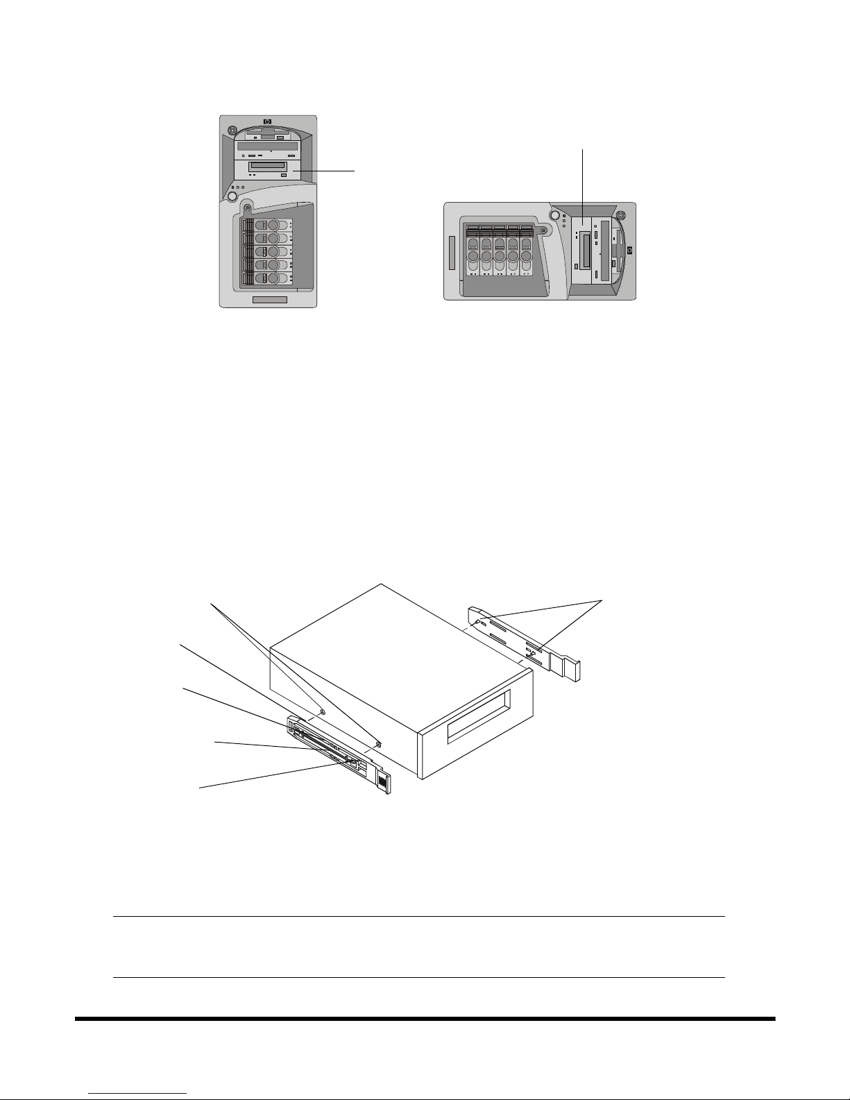
Installing the Plastic Rails (Models DAT 24i and DAT 40i)
The plastic drive rails are secured to the drive by spring tension.
To install the plastic drive rails:
1. Insert one end of the wire rod on the rail into the mounting hole at the rear of the drive (Figure 2).
2. Apply pressure to the middleof the railallowingthe remaining wire rod end to beinsertedinto the mounting hole at
the front of the drive. Ensure that the rail is seated against the side of the drive.
3. Repeat the installation for the second mounting rail.
Figure 2. Plastic Drive Rails
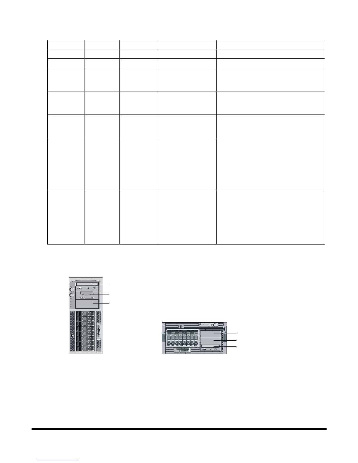
HP Server tc4100 Configuration
The HP Server tc4100 can accept any of the following HP Surestore tape drives:
Figure 1. HP Surestore Supported Locations for the HP Server tc3100
NOTE In any of theseserverconfigurations, the CD-ROM isnormallymounted in location
P1 in the pedestal configuration and in location R3 in the rack mount configuration
(see Figure 3).
Pedestal
Shelf Mount
P2 Location
R2 Location
Wire Rod Ends
Mounting Holes
Wire Rod
Insert this wire
rod end last
Apply pressure
to m iddle of rail
Insert this wire rod
end first
HP Part Number 5990-3463 3
Installing the Plastic Rails (Models DAT 24i and DAT 40i)
The plastic drive rails are secured to the drive by spring tension.
To install the plastic drive rails:
Table 2. HP Surestore Tape Drives for the HP Server tc4100
Drive Part No. Size Supported Location Comments
DAT 24i C1555D Half Height R1, R2, P2, P3 Use the plastic drive rails when installing.
DAT 40i C5686A Half Height R1, R2, P2, P3 Use the plastic drive rails when installing.
DAT 40x6i C5716A Full Height R1 and R2, P2 and P3
(Two HH slots are
required)
Use t he metal drive rails when installing on
the server.
DAT 24X6i C5677B F ull Height R1 and R2, P2 and P3
(Two HH slots are
required)
Use t he metal drive rails when installing on
the server.
Ultrium 230i C7400A Full Height R1 and R2, P2 and P3
(Two HH slots are
required)
Use t he metal drive rails when installing on
the server.
DLT VS80i C7504A Half Height R1, R2, P2, P3 If this drive is installed in position P2 or P3,
it is necessary to remove the power
protection bracket of the server.
See “Clearance Considerations (Model
C7504A or C7420A)” on page 5
Use t he metal drive rails when installing on
the server.
Ultrium 215i C7420A Half Height R1, R2, P2, P3 If this drive is installed in position P2 or P3,
it is necessary to remove the power
protection bracket of the server.
See “Clearance Considerations (Model
C7504A or C7420A)” on page 5
Use t he metal drive rails when installing on
the server.
Figure 3. HP Surestore Supported Locations for the HP Server tc4100
0
1
1
1
Rack Mount
Pedestal
P1 CD-ROM
P2 Location
P3 Location
R3 CD-ROM
R2 Location
R1 Location
 Loading...