


HP SureStore DLT Autoloader
Models 418, 718 & 818
User’s Guide
Edition 1
Manufacturing Part Number: C6282-90009
September 1999
Printed in: Greeley, CO USA
© Copyright 1999 Hewlett-Packard Company

Notice
This document contains information that is protected by copyright. All
rights are reserved. No part of this document may be photocopied,
reproduced, or translated to another language. The information
contained in this document is subject to change without notice.
Hewlett-Packard makes no warranty of any kind with regard to this
printed material, including, but not limited to the implied warranties of
merchantability and fitness for a particular purpose. Hewlett-Packard
shall not be liable for errors contained herein or for incidental or
consequential damages in connection with the furnishing, performance,
or use of this material.
See Appendix B for important safety and regulatory information.
Warranty
NOTE See Appendix A for more information about support and service.
HP PRODUCT: HP SureStore DLT Autoloader Models 418, 718, and 818
DURATION OF LIMITED WARRANTY: 3 years
1. HP warrants HP hardware, accessories, and supplies against defects
in materials and workmanship for the period specified above. If
Hewlett-Packard receives notice of such defects during the warranty
period, Hewlett-Packard will, at its option, either repair or replace
products which prove to be defective. Replacement products may be
either new or like-new.
2. HP warrants that HP software will not fail to execute its
programming instructions, for the period specified above, due to
defects in material and workmanship when properly installed and
used. If HP receives notice of such defects during the warranty period,
HP will replace software media that does not execute its
programming instructions due to such defects.
ii

3. HP does not warrant that the operation of HP products will be
uninterrupted or error free. If HP is unable, within a reasonable time,
to repair or replace any product to a condition as warranted, customer
will be entitled to a refund of the purchase price upon prompt return
of the product.
4. HP products may contain remanufactured parts equivalent to new in
performance or may have been subject to incidental use.
5. The warranty period begins on the date of delivery or on the date of
installation if installed by HP. If customer schedules or delays HP
installation more than 30 days after delivery, warranty begins on the
31st day from delivery.
6. Warranty does not apply to defects resulting from (a) improper or
inadequate maintenance or calibration, (b) software, interfacing,
parts or supplies not supplied by HP, (c) unauthorized modification or
misuse, (d) operation outside of the published environmental
specifications for the products, or (e) improper site preparation or
maintenance.
7. TO THE EXTENT ALLOWED BY LOCAL LAW, THE ABOVE
WARRANTIES ARE EXCLUSIVE AND NO OTHER WARRANTY
OR CONDITION, WHETHER WRITTEN OR ORAL, IS EXPRESSED
OR IMPLIED AND HP SPECIFICALLY DISCLAIMS ANY IMPLIED
WARRANTIES OR CONDITIONS OF MERCHANTABILITY,
SATISFACTORY QUALITY, AND FITNESS FOR A PARTICULAR
PURPOSE.
8. HP will be liable for damage to tangible property per incident up to
the greater of $300,000 or the actual amount paid for the product that
is the subject of the claim, and for damages for bodily injury or death,
to the extent that all such damages are determined by a court of
competent jurisdiction to have been directly caused by a defective HP
product.
9. TO THE EXTENT ALLOWED BY LOCAL LAW, THE REMEDIES IN
THIS WARRANTY STATEMENT ARE THE CUSTOMER’S SOLE
AND EXCLUSIVE REMEDIES. EXCEPT AS INDICATED ABOVE,
IN NO EVENT WILL HP OR ITS SUPPLIERS BE LIABLE FOR
LOSS OF DATA OR FOR DIRECT, SPECIAL, INCIDENTAL,
CONSEQUENTIAL (INCLUDING LOST PROFIT OR DATA), OR
OTHER DAMAGE, WHETHER BASED IN CONTRACT, TORT, OR
OTHERWISE.
iii

Printing History
New editions of this manual incorporate all material updated since the
previous edition. The manual printing date and part number indicate the
current edition. The printing date changes when a new edition is printed.
(Minor corrections and updates incorporated at reprint do not change
this date.)
Edition 1: September 1999: Initial printing
iv

Typographical Conventions and Terms
The following typographical conventions are used in this manual:
Italic font: Denotes important information.
Keycap : Keys on the Autoloader.
Computer Output: Information displayed in the control panel and screen menu items that you select.
Menu Path: Series of menus that you need to enter to access the menu currently being described.
WARNING Warnings call attention to a procedure or practice that could
result in personal injury if not correctly performed. Do not
proceed until you fully understand and meet the required
conditions.
CAUTION Cautions call attention to an operating procedure or practice that could
damage the product if not correctly performed. Do not proceed until
understanding and meeting these required conditions.
NOTE Notes provide information that can be helpful in understanding the
operation of the product.
v

In This Manual
In this manual, the following areas are described:
Chapter 1 Getting Started: Describes how to install, connect,
power on, and move the Autoloader.
Chapter 2 Operating the Autoloader: Describes how to operate
the control panel, set administrative options, and
troubleshoot.
Chapter 3 Using and Maintaining Tapes: Describes how to use
and care for tapes.
Appendix A Support and Customer Service: Describes how to get
support for the Autoloader and how to order parts.
Appendix B Safety and Regulatory: Describes safety and regulatory
information for the Autoloader.
Appendix C TapeAlert Messages: Describes the TapeAlert
messages.
Appendix D Installing an Autoloader Into a Non-HP Rack:
Describes how to install the Autoloader into a non-HP
rack.
vi

Contents
1. Getting Started
Chapter Overview................................................................................. 1-2
Product Components ............................................................................ 1-3
Installation Overview...........................................................................1-4
Autoloader Rear Panel................................................................... 1-5
Choosing a Location.......................................................................1-6
Mounting the Autoloader in a Rack..............................................1-7
Tools and Components.............................................................1-7
Mounting the Autoloader ........................................................ 1-8
Connecting the Autoloader...................................................................1-15
T
a
b
l
e
o
f
C
o
n
t
e
n
t
s
Powering on the System....................................................................... 1-18
Installing the SCSI Bus Adapter ......................................................... 1-19
Moving or Shipping the Autoloader.....................................................1-20
Moving the Autoloader...................................................................1-20
Shipping the Autoloader................................................................ 1-22
2. Operating the Autoloader
Chapter Overview................................................................................. 2-2
Loading/Unloading Tapes.....................................................................2-3
Inserting and Removing Tapes with Software ............................. 2-3
Opening the Door ........................................................................... 2-3
Alternate Door Open Method.................................................. 2-3
Removing the Magazine .......................................................... 2-4
Inserting the Magazine ........................................................... 2-5
Loading Tapes .......................................................................... 2-5
Unloading Tapes ......................................................................2-7
Autoloader Control Panel..................................................................... 2-8
vii

Contents
Understanding Control Panel Messages............................................. 2-9
Tape Status .................................................................................... 2-9
Drive/Autoloader Status................................................................ 2-10
Autoloader Display Menu Tree............................................................ 2-11
Top-Level Menu Options...................................................................... 2-12
Password-Protected Functions...................................................... 2-15
Entering the Administration Menu Password.................................... 2-17
Changing the Administration Menu Password .................................. 2-18
Setting or Viewing SCSI IDs ............................................................... 2-19
Setting SCSI IDs............................................................................ 2-19
Viewing SCSI IDs .......................................................................... 2-20
Cleaning the Autoloader Tape Drive................................................... 2-21
Drive Cleaning Errors.......................................................................... 2-23
Configuring the Autoloader ................................................................. 2-24
Retrieving Autoloader Information..................................................... 2-27
Running an Internal Test .................................................................... 2-28
Upgrading Firmware............................................................................ 2-33
Upgrading Drive Firmware from Tape ......................................... 2-33
Troubleshooting.................................................................................... 2-34
Understanding Error Messages........................................................... 2-42
3. Using and Maintaining Tapes
Chapter Overview ................................................................................ 3-2
Labeling Tape Cartridges ................................................................... 3-3
Labeling the Magazine......................................................................... 3-4
viii

Contents
Write-Protecting Tape Cartridges ....................................................... 3-5
Maintaining Tape Cartridges............................................................... 3-6
Do Not:............................................................................................ 3-6
Do: ................................................................................................... 3-6
Inspecting Tape Cartridges.................................................................. 3-7
DO NOT Use Cartridges:............................................................... 3-8
A. Support and Customer Service
Supplies and Accessories......................................................................A-2
Hewlett-Packard Customer Support ...................................................A-3
T
a
b
l
e
o
f
C
o
n
t
e
n
t
s
Information Needed for Support ...................................................A-3
Faxback Services ............................................................................ A-4
Hewlett-Packard Web Site............................................................. A-4
Telephone Support During Warranty............................................A-5
North and South America ....................................................... A-5
European Customer Support Centers .................................... A-5
Asia Pacific Customer Support Centers ................................. A-7
Elsewhere................................................................................. A-7
Telephone Support After Warranty............................................... A-8
US and Canada ........................................................................ A-8
Europe ...................................................................................... A-8
Elsewhere................................................................................. A-8
HP Reseller Locator Numbers ................................................ A-8
B. Safety and Regulatory
Chapter Overview................................................................................. B-2
Regulatory Information........................................................................ B-3
United Kingdom Telecommunications Act 1984 ..........................B-4
ix

Contents
Herstellerbescheinigung................................................................ B-4
English Translation of German Sound Emission Directive ........ B-4
Japanese Harmonics Statement ................................................... B-5
Japanese VCCI Class B Statement............................................... B-5
English Translation ................................................................ B-5
Taiwan Class A Warning Statement............................................. B-6
For HP DLT Library Model 718 (C6282L, C6280J, A5501A) B-6
Taiwan Class A Warning Statement............................................. B-6
For HP DLT Library Model 418 (C6280F and C6280H) ....... B-6
C. TapeAlert Messages
Overview............................................................................................... C-2
TapeAlert Messages and Descriptions ................................................ C-3
D. Installing an Autoloader into a Non-HP Rack
Mounting the Autoloader in a Non-HP Rack...................................... D-2
Tools and Components................................................................... D-2
Mounting the Autoloader .............................................................. D-3
Cable Management........................................................................ D-9
x

Figures
Figure1-1.RearPanelFeatures...............................1-5
Figure1-2.RackKitParts ...................................1-7
Figure1-3.ClipnutandScrewInstallation......................1-8
Figure1-4.InstallationWithSpaceAboveBezel .................1-9
Figure1-5.InstallationWithoutSpaceAboveBezel...............1-9
Figure1-6.ShelfInstallation................................1-10
Figure 1-7. Filler Panel Installation...........................1-11
Figure1-8.RemovingtheCoverandFeet......................1-12
Figure1-9.SecuringtheAutoloader ..........................1-13
T
a
b
l
e
o
f
C
o
n
t
e
n
t
s
Figure1-10.CableManagement..............................1-14
Figure1-11.AutoloaderastheOnlyPeripheral .................1-16
Figure1-12.AutoloaderwithOtherPeripherals.................1-17
Figure1-13.UnboltingtheAutoloader ........................1-21
Figure2-1.RemovingtheMagazine............................2-4
Figure2-2.LoadingTapesintotheMagazine....................2-5
Figure2-3.LoadingInternalSlots.............................2-6
Figure3-1.LabelPosition....................................3-3
Figure3-2.MagazineLabelPosition ...........................3-4
Figure3-3.Write-ProtectButtonSettings.......................3-5
Figure3-4.LeaderBucklingLoop .............................3-7
FigureD-1.RackKitParts...................................D-2
FigureD-2.ClipnutandScrewInstallation......................D-3
FigureD-3.CustomizingtheShelfDepth .......................D-4
xi

Figures
FigureD-4.ShelfInstallation................................ D-5
FigureD-5.TightentheScrews............................... D-6
Figure D-6. Filler Panel Installation. . ......................... D-7
FigureD-7.SecuringtheAutoloader .......................... D-8
FigureD-8.CableManagement .............................. D-9
xii

Table s
Table 1-1. Components Provided .......................................................1-3
Table 1-2. Location Criteria ...............................................................1-6
Table 1-3. Technical Specifications....................................................1-6
Table 2-1. Top-Level Menus...............................................................2-12
Table 2-2. Admin Menu Options........................................................2-15
Table 2-3. Drive Cleaning Troubleshooting ......................................2-23
Table 2-4. Configuration Options ......................................................2-24
Table 2-5. Information Logs...............................................................2-27
Table 2-6. Tests Available from the Control Panel...........................2-28
T
a
b
l
e
o
f
C
o
n
t
e
n
t
s
Table 2-7. Troubleshooting Table ...................................................... 2-32
Table 2-8. Common Error Codes........................................................2-41
Table C-1. TapeAlert Tape Drive Error Messages............................C-3
Table C-2. TapeAlert Tape Library Error Messages ........................C-7
xiii

Table s
xiv

G
e
t
t
i
n
g
S
t
a
r
t
e
d
1GettingStarted
1-1

Getting Started
Chapter Overview
Chapter Overview
This chapter explains the following:
• Identifying product components
• Choosing a location
• Installing the Autoloader
• Connecting the Autoloader
• Powering on the system
• Installing the SCSI bus adapter
• Moving the Autoloader
• Shipping the Autoloader
1-2 Chapter 1

Product Components
Table 1-1 describes the parts that are provided with the Autoloader.
Table 1-1 Components Provided
Product Name Description
SCSI cables Connects the Autoloader to the host. Cable
length is 2 meters.
SCSI terminator 68-pin terminator terminates power at the end
of a SCSI chain.
SCSI jumper cable Connects the drive and SCSI controller board.
SCSI bus adapter Matches the interface type of the Autoloader.
Power cord Localized power cord supplies power.
Data cartridges Five type IV DLTtape
backup.
Getting Started
Product Components
Ô
cartridges for data
G
e
t
t
i
n
g
S
t
a
r
t
e
d
Cleaning cartridge One cartridge included for cleaning the tape
drive head.
Installation poster Displays simplified installation instructions.
Live trial software One shrink-wrapped package for trial use.
Contact software vendor for licensing
information.
User’s Guide Contains installation, operation, and
troubleshooting information.
SureStore Tape CD-ROM
Contains diagnostic utilities, backup software
information, and localized versions of the user’s
guide and installation poster.
Chapter 1 1-3

Getting Started
Installation Overview
Installation Overview
Before installing the Autoloader:
• Make sure you have the components listed in Table 1-1 on page 1-3.
• Become familiar with the back of the Autoloader, as shown in
Figure 1-1 on page 1-5.
Installing the Autoloader requires:
1. Choosing a suitable location.
2. Mounting the Autoloader in a rack (rackmount configuration only).
3. Connecting the Autoloader.
4. Powering on the system.
These steps are explained in this chapter.
NOTE After unpacking the Autoloader, save the shipping carton and accessory
kit carton. These items may be reused if future shipping becomes
necessary.
1-4 Chapter 1
Getting Started
Installation Overview
Autoloader Rear Panel
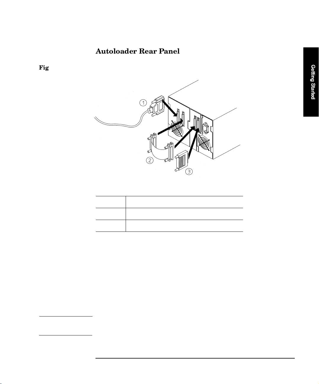
Figure 1-1 Rear Panel Features
1 SCSI cable connector to host SCSI port
2SCSIjumpercable
G
e
t
t
i
n
g
S
t
a
r
t
e
d
3SCSIterminator
The Autoloader can be connected to the host system in one of two configurations:
Standard
configuration: Connects the drive and the Autoloader with an
external jumper cable on one SCSI bus, as shown in
Figure 1-1.
Advanced configuration: Connects the drive and autoloader controller to the
host using separate SCSI buses.
NOTE The advanced configuration requires an additional terminator that is not
provided.
Chapter 1 1-5

Getting Started
Installation Overview
Choosing a Location
Choose a location that meets the following criteria:
Table 1-2 Location Criteria
Room temperature 50–104° F (10–40 C)
Power source AC power voltage: 100–127V or 200–240V
Air quality Minimal particulate contamination. Avoid areas
Auto Ranging
Current Rating: 100–127V, 1.8A, 50/60 HZ,
220–240V, .9A, 50/60 HZ Auto Ranging
Maximum Watts: 100 Watts, 100-127V (60 HZ)
Maximum Watts: 90 Watts, 200-240V (50 HZ)
near frequently used doors and walkways,
stacks of supplies that collect dust, smoke-filled
rooms, large or high-speed printers. Do not use
filters.
Caution: Excessive dust and debris can damage
the tapes and the tape drive.
Adequate clearance
Table 1-3 Technical Specifications
Dimensions Height: 7.35 inches (18.7 cm)
Acoustics 58 Decibels Sound Pressure
1-6 Chapter 1
Desktop configuration—free standing:
Back 6 inches/ 15 cm
Front 8 inches/ 20 cm
Sides 1 inch/ 2.5 cm
Rackmount configuration—requires 5 EIA units
inarack(1EIA=1.75inchesor4.5mm)
Width: 8.9 inches (22.6 cm)
Depth: 22 inches (55.9 cm
Weight: 31.5 pounds (14.3 kg)
Getting Started
Installation Overview
Mounting the Autoloader in a Rack
NOTE For instructions on installing the Autoloader into a non-HP rack, refer to
“Installing an Autoloader into a Non-HP Rack” on page D-1.
Too ls and Comp onen t s
Beforeyoubegin,makesureyouhavethefollowing:
Too ls :
#2 Phillips screwdriver
Kit Components (parts are labeled for easy identification):
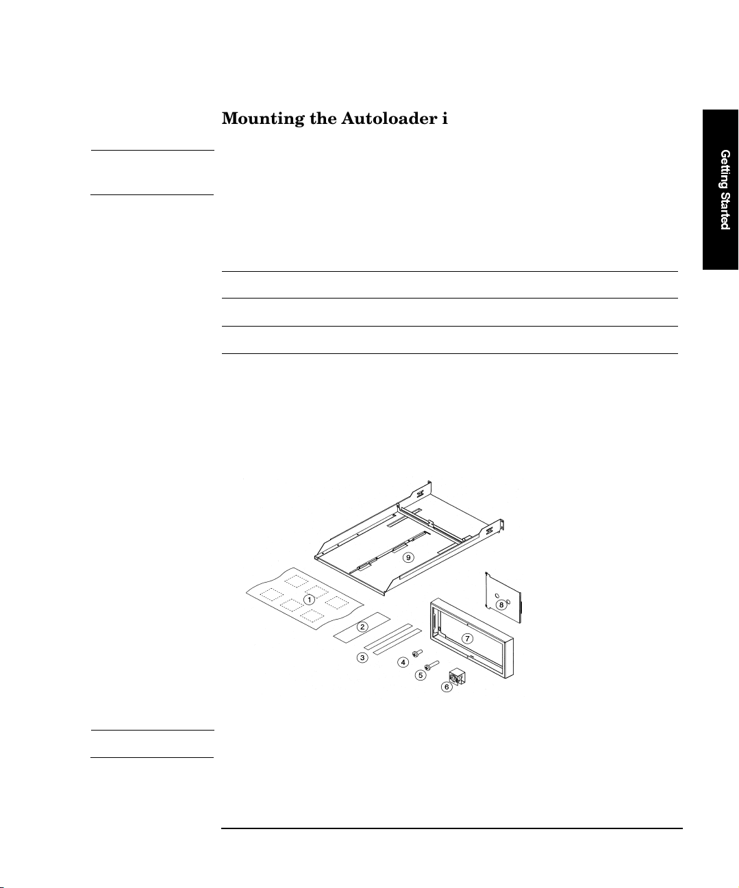
1. Installation poster (Qty 1)
2. Template (Qty 2)
3. Cable ties (Qty 2)
4. M4 x 10 mm pan phillips (Qty 4)
5. 10-32 x 5/8 pan phillips (Qty 8)
Figure 1-2 Rack Kit Parts
6. 10-32 clipnuts (Qty 8)
7. Support bezel (Qty 1)
8. Filler panel (Qty 1)
9. Shelf (Qty 1)
G
e
t
t
i
n
g
S
t
a
r
t
e
d
NOTE The rack kit may contain extra parts.
Chapter 1 1-7
Getting Started
Installation Overview
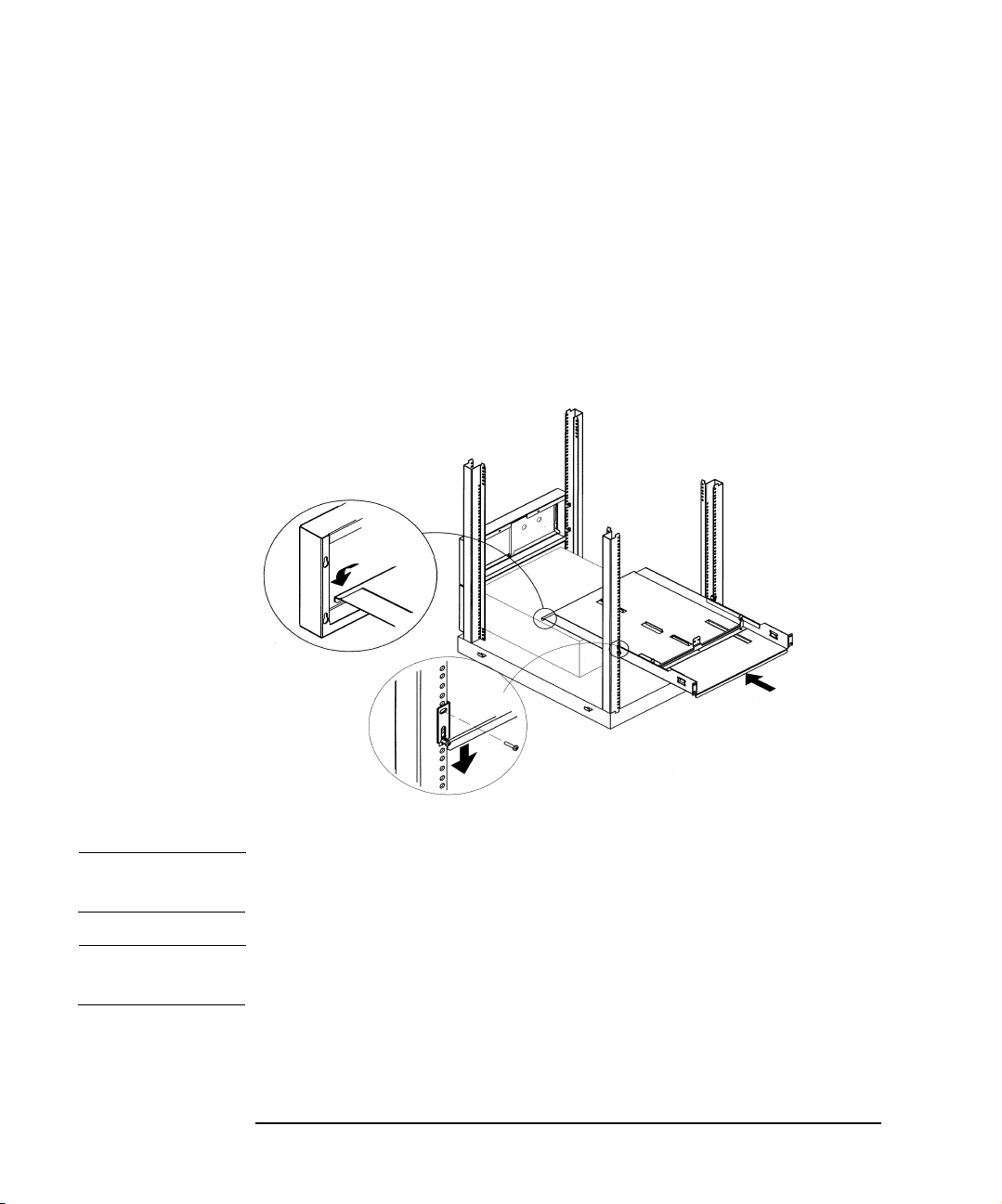
Mounting the Autoloader
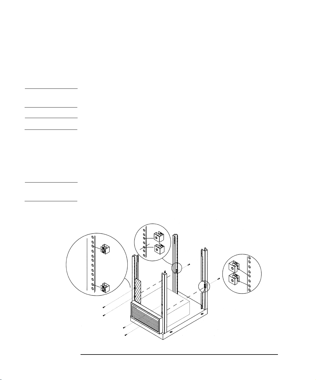
1. Facing the front of the rack and using the template as a guide, install
four clipnuts (two in each rail) above any existing products
(Figure 1-3).
TIP For a level shelf, ensure that the screws are in the same position on the
right and left rail.
NOTE Your rack might look different from the illustrations.
2. Using the template as a guide, install two clipnuts into each back rail
of the rack. The back lower clipnuts should be located in the same
position as the lower clipnuts in the front of the rack (Figure 1-3).
3. Using six 10-32 screws (four in the front and two in the back lower
clipnuts), start a screw into each clipnut and turn 2-3 times.
NOTE If you are installing the unit flushed to the top of the rack, do not install
screws at this time. Instead, proceed to the next step.
Figure 1-3 Clipnut and Screw Installation
1-8 Chapter 1
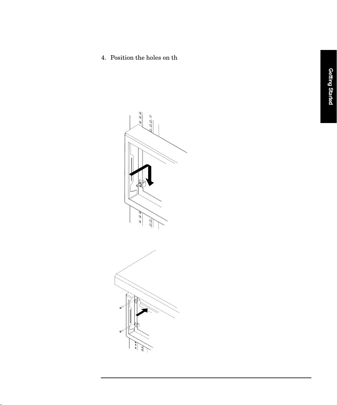
4. Position the holes on the support bezel over the screws on the clipnut,
and slide downward, securing the bezel into place (Figure 1-4). If you
are installing the Autoloader flushed to the top of the rack, hold the
bezel in place, then install the screws (Figure 1-5). Tighten screws
when complete.
Figure 1-4 Installation With Space Above Bezel
Getting Started
Installation Overview
G
e
t
t
i
n
g
S
t
a
r
t
e
d
Figure 1-5 Installation Without Space Above Bezel
Chapter 1 1-9
Getting Started
Installation Overview
5. Slide the shelf through the back of the rack until the front lip is over
the bezel and the rear portion of the shelf slides over the back screws
(Figure 1-6).
a. Lower the shelf into place, and tighten the screws in the bottom
clipnuts.
b. Insert and tighten two additional screws into the top clipnuts to
secure the shelf.
Figure 1-6 Shelf Installation
NOTE Have a second person stand at the front of the rack to help guide the
front lip of the shelf between the slots on the bezel.
CAUTION Ensure that installation in your rack cabinet does not create an unstable
condition.
1-10 Chapter 1
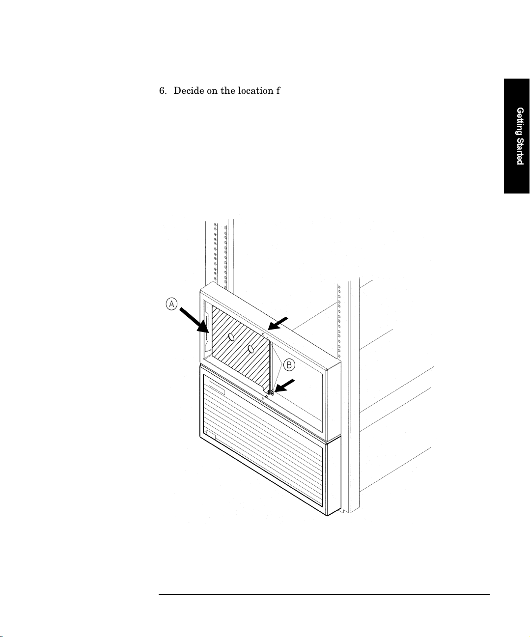
6. Decide on the location for the Autoloader. The filler panel will be
installed on the other side if you are only installing one Autoloader
(Figure 1-7).
a. Reach inside the bezel and insert the filler panel into the slot on
the bezel.
b. Pull the filler panel forward to the inside face of the bezel until it
snaps into position.
Figure 1-7 Filler Panel Installation
Getting Started
Installation Overview
G
e
t
t
i
n
g
S
t
a
r
t
e
d
Chapter 1 1-11
Getting Started
Installation Overview
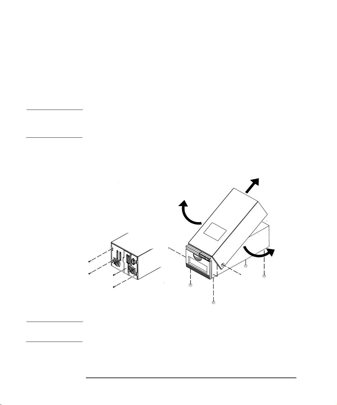
7. Remove the cover and feet on the Autoloader.
a. Remove the four screws on the back of the cover and the two
screws on the side of the cover (Figure 1-8).
b. Remove the cover by pulling the sides of the cover out and lifting it
up.
NOTE The cover may fit tightly near the control panel. If the cover is not easily
removed, pull the sides out near the control panel while lifting up on the
back end of the cover.
c. Unscrew and remove the four feet. You may lay the unit on its side
to remove the feet.
Figure 1-8 Removing the Cover and Feet
NOTE If it later becomes necessary to ship the Autoloader, reattach the cover
and feet before shipping.
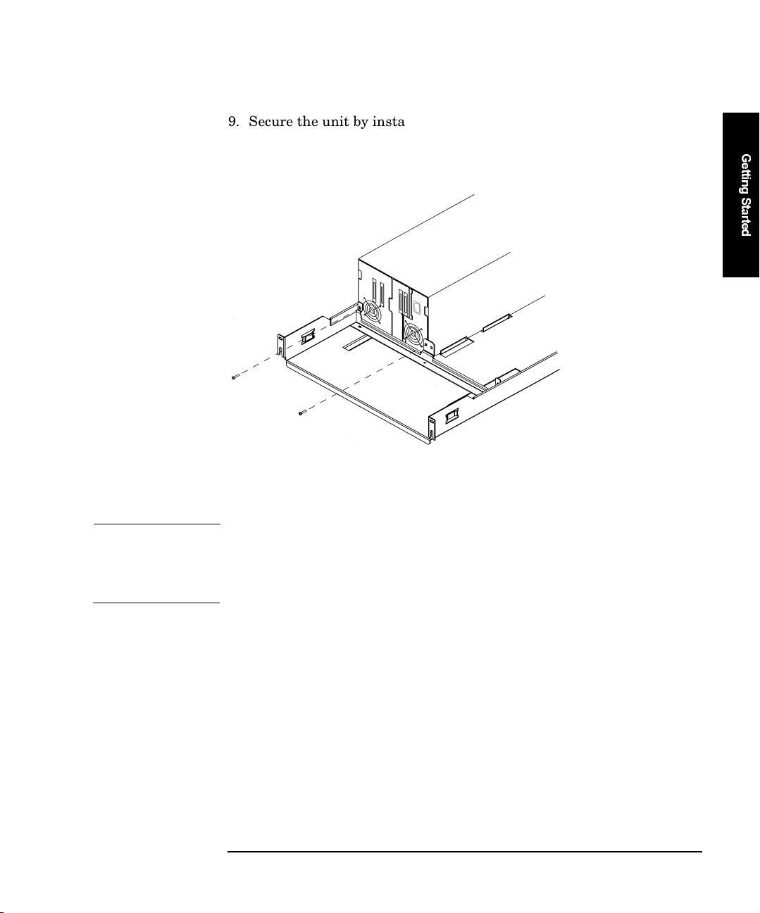
8. From the front of the bezel, slide the Autoloader into the shelf until it
rests firmly against the support bracket.
1-12 Chapter 1
Getting Started
Installation Overview
9. Secure the unit by installing two M4x10 mm screws through the
support bracket and into the rear panel (Figure 1-9).
Figure 1-9 Securing the Autoloader
10.After connecting the external cables, secure the cables to the side of the rack.
G
e
t
t
i
n
g
S
t
a
r
t
e
d
CAUTION Ensure that the SCSI and power cables are properly routed and secured
on rackmounted Autoloaders so that they do not interfere with other
moveable rackmounted products. Failure to properly route cables could
damage them.
a. After connecting external cables described in “Connecting the
Autoloader” on page 1-15, thread one cable tie through the cable
tie mount on the shelf (Figure 1-10 on page 1-14).
b. Gently pull the cables toward the cable tie to secure them to the
back of the shelf.
c. Route the cables through the rack so that they do not interfere
with other rackmounted products.
Chapter 1 1-13

Getting Started
Installation Overview
Figure 1-10 Cable Management
NOTE Save the remaining screws for a possible second Autoloader installation.
CAUTION Be certain that the temperature of the rack cabinet does not exceed the
maximum temperature of 104oF or 40C.
1-14 Chapter 1

Getting Started
Connecting the Autoloader
Connecting the Autoloader
1. Properly shut down all peripheral devices connected to the host
computer.
If the host computer is connected to a network, check with the system
administrator before switching off power.
2. Shut down the host.
If the host does not already have a SCSI bus adapter with a matching
interface type, install the supplied adapter. See “Installing the SCSI
Bus Adapter” on page 1-19 for more information.
3. Connect the long SCSI cable from the Autoloader to the host.
NOTE For maximum performance, do not connect the Autoloader to the same
SCSI bus as the hard drive, another tape drive, or a SCSI RAID
controller.
G
e
t
t
i
n
g
S
t
a
r
t
e
d
4. Connect the SCSI jumper cable to the two inside connectors on the Autoloader.
To install the Autoloader as the only device on the SCSI bus, connect
the cables and terminator as shown in Figure 1-11 on page 1-16.
To install the Autoloader in the middle of a SCSI bus, connect the
cables and terminator as shown in Figure 1-12 on page 1-17.
NOTE If using a single-ended Autoloader with an HVDS host, you must use a
single-ended to wide differential converter, such as HP part number
C4316A converter. To install, connect a wide SCSI cable from the host
differential SCSI port to the differential fast/wide input of the converter.
Connect the single-ended output of the converter to the Autoloader.
Any converter used must be fully SCSI compliant.
Chapter 1 1-15

Getting Started
Connecting the Autoloader
Figure 1-11 Autoloader as the Only Peripheral
1 SCSIcabletohostSCSIport
2SCSIjumpercable
3 SCSI 68-pin terminator
1-16 Chapter 1

Figure 1-12 Autoloader with Other Peripherals
Getting Started
Connecting the Autoloader
G
e
t
t
i
n
g
S
t
a
r
t
e
d
1SCSIcabletohostSCSIport
2 SCSI jumper cable
3 SCSI cable to SCSI port
4 SCSI 68-pin terminator
5. Verify the standby switch on the autoloader control panel is switched
off. Connect the socket end of the power cord into the power port on
the autoloader rear panel.
6. If you are mounting the unit in a rack, secure the cables to the side of
the rack as shown in Figure 1-10 on page 1-14.
7. To power on the unit, see the instructions in “Powering on the
System” on page 1-18.
Chapter 1 1-17

Getting Started
Powering on the System
Powering on the System
WARNING To disconnect primary power, remove the power cord from the
wall receptacle. The standby switch on the front of the unit shuts
down secondary circuits only.
CAUTION Make certain that reliable earth grounding of the rackmounted
equipment and the power tap is maintained.
CAUTION Be certain that the total current of the rack components does not exceed
the current rating of the power tap or outlet receptacle.
1. Power off the host and other peripherals.
2. Connect the power cord into a grounded outlet.
3. If the standby switch is turned off, use a pencil eraser or other similar
tool to switch it on (see “Autoloader Control Panel” on page 2-8).
Initially the messages NOT READY/SELF TEST, NOT READY/INVENTORY CHECK,andNOT READY/CHECK DRIVE will display on the front control panel. After the power-on test completes (approximately 30 seconds), the drive status information appears in the display window.
NOTE If you have problems powering on the unit see “Troubleshooting” on page
2-32.
4. Turn on any other peripherals.
5. Turn on the host.
1-18 Chapter 1

Getting Started
Installing the SCSI Bus Adapter
Installing the SCSI Bus Adapter
Refer to the host computer user’s guide and the card installation
instructions for information on installing the SCSI bus adapter.
Follow these guidelines:
• Make sure that the host has a PCI expansion slot available.
• Power off the host before installation.
• For maximum performance, do not connect other peripherals to the sameSCSIbusastheharddrive.
• If you are using a SCSI bus adapter other than the one provided,
ensure that it matches the Autoloader interface type as shown below.
Model Part Number Interface
418 C6280F Single-Ended SCSI
718 C6280J Single-Ended SCSI
G
e
t
t
i
n
g
S
t
a
r
t
e
d
818 C6282NB
C6282RA
Low Voltage Differential SCSI (LVDS) High Voltage Differential SCSI (HVDS)
CAUTION Do not connect an HVDS Autoloader on a single-ended SCSI bus.
LVDS Autoloaders require an LVDS terminator and can be used on a
single-ended or low voltage differential SCSI bus.
The SCSI specification defines maximum cable lengths for LVDS as:
• 3 meters in single-ended fast/wide mode
• 6 meters in single-ended slow mode
• 12 meters in LVDS mode
• 1.5 meters if a single-ended ultra SCSI device is on the same bus
Chapter 1 1-19

Getting Started
Moving or Shipping the Autoloader
Moving or Shipping the Autoloader
Moving the Autoloader
1. Verify that a tape is not in the drive.
• If the drive is loaded with a tape, unload it before moving the
Autoloader. Refer to the backup software documentation, or use
the UNLOAD menu option (see “Top-Level Menu Options” on page
2-12).
2. Shut down the host if necessary.
CAUTION Notify the system administrator before shutting down the host.
3. Remove the power cord and the host SCSI cable from the autoloader rear panel.
• If the Autoloader is a stand-alone unit, place it onto a cart and
wheel it to its new location. Go to step 5.
• If the Autoloader is rackmounted, follow these steps:
a. Remove the two screws that secure the back of the Autoloader
to the shelf (Figure 1-13 on page 1-21).
b. Remove the filler panel (if necessary), and slide the Autoloader
out of the rack.
c. Move the Autoloader to its new destination.
4. Reinstall the Autoloader into the rack using the rackmount kit
instructions in “Mounting the Autoloader” on page 1-8.
NOTE You will need the rack kit equipment to reinstall the unit into another
rack (Figure 1-2 on page 1-7).
1-20 Chapter 1

Getting Started
Moving or Shipping the Autoloader
Figure 1-13 Unbolting the Autoloader
G
e
t
t
i
n
g
S
t
a
r
t
e
d
5. Reconnect the power cord and SCSI cables. See “Connecting the
Autoloader” on page 1-15.
Chapter 1 1-21

Getting Started
Moving or Shipping the Autoloader
Shipping the Autoloader
1. Verify that a tape is not in the drive.
• If the drive is loaded with a tape, unload it before moving the
Autoloader. Refer to the backup software documentation, or use
the UNLOAD menu option. See “Top-Level Menu Options” on page
2-12.
2. Remove all tape cartridges from the magazine and internal slots, and
return the magazine to the Autoloader.
3. Shut down the host if necessary.
CAUTION Notify the system administrator before shutting down the host.
4. Remove the power cord and the host SCSI cable from the rear panel.
• If the Autoloader is a desktop unit, go to step 5.
• If the Autoloader is rackmounted, follow these steps:
a. Remove the two screws that attach the Autoloader to the shelf
(Figure 1-13 on page 1-21).
b. Remove the filler panel (if necessary), and slide the Autoloader
out of a rack.
NOTE You will need the rack kit equipment to reinstall the unit into another
rack (Figure 1-2 on page 1-7).
5. Repackage the Autoloader in the original packing materials.
If the original packaging materials are not available, contact your
service representative for packaging materials.
CAUTION The Autoloader can be seriously damaged if it is not shipped using
appropriate shipping materials.
1-22 Chapter 1

A
u
t
o
l
o
a
d
e
r
O
p
e
r
a
t
i
o
n
2 Operating the Autoloader
2-1

Operating the Autoloader
Chapter Overview
Chapter Overview
This chapter explains how to:
•Loadandremovetapes
• Load and remove the magazine
• Operate the control panel
• Interpret control panel messages
• Enter and change an administration menu password
•ViewandsetSCSIIDs
• Clean the tape drive
• Interpret drive cleaning errors
• Configure the Autoloader
• Retrieve Autoloader information
•Runinternaltests
• Upgrade firmware
•Troubleshoot
• Interpret common error messages
2-2 Chapter 2

Loading/Unloading Tapes
Operating the Autoloader
Loading/Unloading Tapes
Inserting and Removing Tapes with Software
If you are using a software application to manage tapes in the
Autoloader, check the software documentation for instructions on
inserting and removing them.
Opening the Door
1. Press the NEXT button until RELEASE DOOR is displayed in the control panel.
2. Press
3. Gently open the front access door by pulling down the handle.
ENTER.
• If the drive is empty, the door will release.
• If a tape is loaded in the drive, EMPTY DRIVE NO is displayed. If the
Autoloader is controlled with host software, press
CANCEL to abort. Use the host software to unload the drive.
•Otherwise,press
displayed, and then press
NEXT or PREV until EMPTY DRIVE YES is
ENTER.
ENTER or
UNLOADING DRIVE will be displayed for up to two minutes, followed by DOOR RELEASED.
A
u
t
o
l
o
a
d
e
r
O
p
e
r
a
t
i
o
n
Alternate Door Open Method
1. Press and hold the
CANCEL button for three to five seconds.
2. After hearing a “click,” pull on the door handle to open.
Chapter 2 2-3

Operating the Autoloader
Loading/Unloading Tapes
Removing the Magazine
1. Swing the magazine handle forward until it is perpendicular with the
magazine (Figure 2-1).
2. Pull the magazine straight out.
Figure 2-1 Removing the Magazine
NOTE Remove the magazine to load tapes. If tapes are loaded while the
magazine is in the autoloader, tapes may not be secured inside the slot.
2-4 Chapter 2

Operating the Autoloader
Loading/Unloading Tapes
Inserting the Magazine
1. With the magazine handle facing out the front of the Autoloader, slide
the magazine into the Autoloader until it “clicks” into place
(Figure 2-1 on page 2-4).
2. Swing the magazine handle to the left to store.
3. Gently shut the front access door.
NOTE The INVENTORY CHECK runs whenever the front access door closes so that
an inventory of storage slot locations can be stored into memory. This
process takes approximately thirty seconds. The inventory check will not
run if the door is not completely shut, or if magazine is not completely
inserted.
Loading Tapes
The Autoloader has two internal storage slots inside the unit (slot
numbers 7 and 8) and six storage slots in the removable magazine (slot
numbers 1-6).
1. With the write-protect switch facing out and at the top, load tapes
into the magazine by pushing the tape in until it “clicks.” If the tape
does not “click” into place and the magazine is inside the autoloader,
remove the magazine to load the tape. A metal tab should release to
lockthetapeintoplace(Figure2-2).
Figure 2-2 Loading Tapes into the Magazine
A
u
t
o
l
o
a
d
e
r
O
p
e
r
a
t
i
o
n
Chapter 2 2-5

Operating the Autoloader
Loading/Unloading Tapes
CAUTION Discharge static by touching the internal sheet-metal panel on the left
side of the unit. Take care not to touch internal electronics.
NOTE If the metal tab is already in the “Up” position, place the corner of the
tape on the tab, and slide the tape into the slot. The latching mechanism
will not click since the tab is already engaged. When tapes are “locked”
into the magazine, the tapes will not fall out if the magazine is turned.
2. With the write-protect switch facing out of the Autoloader and at the
top, load internal slots by pushing the tape in until it “clicks.”
NOTE Themagazinemustberemovedtoloadtheinternalslots(Figure2-3).
Figure 2-3 Loading Internal Slots
3. With the magazine handle facing out the front of the Autoloader, slide
the magazine into the Autoloader until it “clicks” into place
(Figure 2-1 on page 2-4).
4. Swing the magazine handle to the left to store.
5. Gently shut the front access door.
2-6 Chapter 2

Operating the Autoloader
Loading/Unloading Tapes
NOTE The INVENTORY CHECK runs whenever the front access door closes so that
an inventory of storage slot locations can be stored into memory. This
process takes approximately thirty seconds. The inventory check will not
run if the door is not completely shut.
Unloading Tapes
1. Remove the magazine by following the steps under “Opening the
Door” on page 2-3 and “Removing the Magazine” on page 2-4.
2. Unload tapes from the magazine by pressing the tape in until it clicks
and releases. Remove it after it partially ejects.
A
u
t
o
l
o
a
d
e
r
O
p
e
r
a
t
i
o
n
Chapter 2 2-7

Operating the Autoloader
Autoloader Control Panel
Autoloader Control Panel
1 Control panel
keys
PREV: Scrolls the control panel choice backward by one.
NEXT: Scrolls the control panel choice forward by one.
ENTER: Selects the option currently being displayed.
CANCEL: Cancels the current selection or steps you back to the
previous menu.
2 Activity light Steady green: Power is on.
Flashing green: A tape is being accessed.
Amber: An error occurred (see “Troubleshooting” on page 2-32).
3Twoline,
16-character
display
Displays the current operation or drive status. An asterisk (*)
indicates a submenu for that task. Press
ENTER on the control panel
to access that menu.
4 Standby switch Puts the unit’s power in standby mode. Turns off secondary circuits
only.
2-8 Chapter 2

Operating the Autoloader
Understanding Control Panel Messages
Understanding Control Panel Messages
The control panel window is a two-line display with 16 characters per
line that shows the status of the Autoloader or the current function.
Tape Status
The following example shows the display when the Autoloader is in the ready state.
The numbers on the top line show that slots 1, 2, 3, 5, and 8 contain
tapes, tape 4 is in the drive, and slots 6 and 7 are empty.
A
u
t
o
l
o
a
d
e
r
O
p
e
r
a
t
i
o
n
• A blinking number indicates that the tape is being moved from a slot or the drive.
• If a tape is in the drive, the number remains lit and is underlined (tape4inthefigureabove).
• If the Autoloader is empty, the top line reads STATUS EMPTY.Onthe bottom line, the display will read LOADER READY or a drive activity message and can include one of these indicators (represented by the shaded boxes above):
C is always displayed if the drive needs cleaning. If the drive is not
active, CLEAN DRIVE will also display.
WP is displayed if a tape is write protected.
NOTE In a menu option (other than a test menu), the Autoloader defaults to the
drive status display when there has been no user interaction for three
minutes.
Chapter 2 2-9

Operating the Autoloader
Understanding Control Panel Messages
Drive/Autoloader Status
The top display line normally shows the slot status or the current menu.
The bottom display line shows the drive/loader activity unless a control
panel menu has been selected. See “Top-Level Menu Options” on
page 2-12.
The status of the drive and Autoloader is indicated by the following:
• LOADER READY
• LOADER ACTIVE
• DRIVE IDLE
• CLEANING
• WRITING
• READING
• REWINDING
• SEEKING
• ERASING
• LOADING
• UNLOADING
• NO DRIVE (Displays if the drive isn’t functioning properly)
2-10 Chapter 2

Autoloader Display Menu Tree
Autoloader Display Menu Tree
Operating the Autoloader
A
u
t
o
l
o
a
d
e
r
O
p
e
r
a
t
i
o
n
Chapter 2 2-11

Operating the Autoloader
Top-Level Menu Options
Top-Level Menu Options
NOTE To move through the menus, use the control panel keys. If a menu
selection is flashing, press
indicates sub-level menus.
ENTER to select that option. An asterisk (*)
The top-level menu contains the options listed in Table 2-1. Press
or NEXT when the Autoloader is not performing power-on self tests to
view these menus:
Tab l e 2-1 To p- L e v el M enus
Option Function
RELEASE DOOR * Unlocks the access door. See “Opening the Door” on page 2-3
LOAD TAPE * Moves a tape from a slot to the drive.
• The second line displays FROM SLOT with the slot number.
•Press
•Press
The first full slot is the default slot. Only slots containing tapes can be selected.
UNLOAD TAPE * Unloads a tape from the drive to the slot it came from.
ADMIN * All functions under this menu option are password protected. See
“Password-Protected Functions” on page 2-15.
NEXT until the desired slot number displays.
ENTER to select the slot number.
PREV
2-12 Chapter 2

Tab l e 2-1 To p- L e v el M enus
Option Function
Operating the Autoloader
Top-Level Menu Options
OPERATING MODE *
(There are three operating modes.)
• AUTODETECT MODE (default mode): Operates as if in
Stacker mode until receiving a SCSI changer command. It then
operates in Random mode until power cycled. (See descriptions
of Random and Stacker modes that follow.)
Changer commands are: INITIALIZE ELEMENT STATUS, READ ELEMENT STATUS, POSITION TO ELEMENT, MOVE MEDIA, and EXCHANGE MEDIA. After receiving one of these commands, the
Autoloader operates as if in Random mode.
• RANDOM MODE: Allows random access to tapes.
Mode: In Random mode, the drive and the autoloader controller
canbeaccessedviatheSCSIbus.Allstackerfeaturesare
disabled after selecting Random mode. Tape cartridges can only
be moved by using host SCSI commands to the Autoloader or by
using the LOAD/UNLOAD front panel menu.
Operation: The SCSI interface for the Autoloader in Random
mode conforms to the SCSI-2 command specification for tape
changer devices.
A
u
t
o
l
o
a
d
e
r
O
p
e
r
a
t
i
o
n
Chapter 2 2-13

Operating the Autoloader
Top-Level Menu Options
Tab l e 2-1 To p- L e v el M enus
Option Function
OPERATING MODE *
(continued)
• STACKER MODE: Loads each tape sequentially after each drive unload request.
Mode: When in Stacker mode, the autoloader controller will not
use an ID and cannot be accessed from the SCSI bus. Only the
drive ID is available. In this mode, the jumper cable may be
removed from the back of the Autoloader, but it will not impact
the system to leave it connected.
Operation: An autoload option and circular mode option is available under the CONFIG menu.
If the autoload option is selected, the first available tape loads
into an empty drive at power up. By default, autoload is off so
that the user must use the front-panel LOAD command to load
tape cartridges. When the host issues a SCSI unload command
to the drive, the Autoloader automatically removes the tape
cartridges from the drive and inserts the next available tape.
If the circular mode option has been selected in CONFIG,the Autoloader will reload the first tape cartridge. If circular is disabled and the last tape cartridge has been unloaded, the Autoloader stops operating until the user loads more tape cartridges.
While in Stacker Mode, if the Autoloader encounters a cleaning
cartridge during the cycle, it will be loaded into the drive as
normal, but will be automatically unloaded after the cleaning
cycle. If the user indicates which slot contains the cleaning
cartridge via the clean drive menu, the Autoloader will skip that
slot.
2-14 Chapter 2

Password-Protected Functions
All ADMIN * functions are password protected.
1. Before accessing the following options, enter the password. (See page 2-17.)
A default password of 000-000-000 is set at the factory. Change this
password when first using the Autoloader if it is in an unsecured
location. (See page 2-18.) Ensure that you document this new
password and keep it safe.
Tab l e 2-2 Admi n M enu Options
Option Function
INFO * Retrieves performance information stored
CLEAN DRIVE * Allows the user to clean the drive.
SCSI IDs * Displays or sets the SCSI addresses for the
Operating the Autoloader
Top-Level Menu Options
in the Autoloader.
autoloader controller and drive.
A
u
t
o
l
o
a
d
e
r
O
p
e
r
a
t
i
o
n
CONFIG * Customizes the autoloader functions. See
“Configuring the Autoloader” on page 2-24.
UPDATE DRIVE FW * Allowstheusertoupdatethefirmwarein
the drive. See “Upgrading Firmware” on
page 2-31.
TEST * Runs internal autoloader tests. See
“Running an Internal Test” on page 2-28.
OVERRIDE DOOR Emergency door release that does not check
the internal state of the Autoloader.
2. When a changeable menu selection is flashing, press the option, or press
PREV or NEXT to display other available options.
ENTER to select
Chapter 2 2-15

Operating the Autoloader
Top-Level Menu Options
3. Press ENTER to select the flashing item.
The “Autoloader Display Menu Tree” on page 2-11 shows the
autoloader menu options available throughout the control panel. To
select the functions listed below the shaded boxes:
a. Press
b. Press
ENTER when that option is displayed.
PREV or NEXT to scroll through the list.
c. To perform the displayed operation, press
ENTER.
2-16 Chapter 2

Operating the Autoloader
Entering the Administration Menu Password
Entering the Administration Menu Password
A numeric password is required to access functions within the ADMIN * menu. A default password of 000-000-000 is set at the factory, which can be used when the Autoloader is powered on for the first time.
1. Starting at the top-level menu, press display window.
2. Press
ENTER.
The default password displays, and the first set of zeros flashes.
3. Press
ENTER to accept the first set of flashing zeros or NEXT/PREV to
change the values.
NEXT until ADMIN * is in the
A
u
t
o
l
o
a
d
e
r
O
p
e
r
a
t
i
o
n
4. Press
ENTER to accept the second set of flashing zeros or NEXT/PREV
to change the values.
5. Press
ENTER to accept the last set of flashing zeros or NEXT/PREV to
change the values.
INFO * displays.
6. Press
PREV or NEXT until the desired function displays, then press
ENTER.
Chapter 2 2-17

Operating the Autoloader
Changing the Administration Menu Password
Changing the Administration Menu Password
ADMIN * / CONFIG*/NEWPASSWORD
Change the password so that only authorized persons can access the
Autoloader and change operation settings.
NOTE Be sure you document a new password and keep it safe. If you forget the
password, only a service representative can restore the default password.
1. Complete steps 1 through 6 in “Entering the Administration Menu
Password” on page 2-17.
2. Press
3. Press
NEXT until CONFIG * displays, and press ENTER.
NEXT or PREV until NEW PASSWORD displays, and press ENTER.
NEW 000 000 000 displays, and the first set of zeros flashes.
4. Press
NEXT or PREV until the new number for the first part of the
password displays, then press
ENTER to select.
The second set of zeros flashes.
5. Press
NEXT or PREV until the new number for the second part of the
password displays, then press
ENTER to select.
The last set of zeros flashes.
6. Press
NEXT or PREV until the new number you wish to assign to the
third part of the password displays, and press
ENTER to select.
PASSWORD CHANGED displays, which indicates that the password has
been saved to non-volatile RAM.
7. Press
CANCEL three times to return to the ready state.
NOTE After changing the password, you can save the new password to flash
ROM by power cycling the Autoloader, which allows the password to be
recovered if the Autoloader is powered off for more than ten days. If this
step is not completed, the password changes may be lost.
Consult your system administrator before power cycling.
2-18 Chapter 2

Operating the Autoloader
Setting or Viewing SCSI IDs
Setting or Viewing SCSI IDs
ADMIN * / SCSI IDs *
NOTE If other peripherals are on the same SCSI bus, check to see which IDs are
available.
When you choose SCSI IDs, you have two options:
• SET IDs * assigns a SCSI ID to the autoloader controller and a SCSI
ID to the drive.
• VIEW IDs * displays the autoloader controller and drive settings.
Device Default SCSI IDs
Autoloader ID 1
A
u
t
o
l
o
a
d
e
r
O
p
e
r
a
t
i
o
n
Drive ID 0
Setting SCSI IDs
ADMIN * / SCSI IDs * / SET IDs *
1. When SET IDs * is displayed, press ENTER.
• AUTOLOADER ID #, DRIVE ID #,orUPDATE IDS NOW (use this last
function after changing IDs to save) is displayed.
• AUTOLOADER ID # stands for the current SCSI ID of the autoloader
controller. DRIVE ID # is the current SCSI ID of the drive.
2. Press
3. Press
Chapter 2 2-19
NEXT until the setting that you want to change is displayed,
and then press
NEXT or PREV until the new SCSI address is displayed, and
then press
ENTER. The current SCSI address flashes.
ENTER.

Operating the Autoloader
Setting or Viewing SCSI IDs
4. Press NEXT until UPDATE IDs NOW is displayed, and press ENTER.
One of the following messages is displayed:
• If the drive and controller are set to the same ID, CONFLICT-ABORTED displays, followed by SET IDs *.
• If the new settings are accepted, IDs SAVED then SCSI IDs * is displayed.
• If a drive serial communications error is detected while trying to set the SCSI IDs, DRV CONNECT ERR displays, followed by IDs NOT
CHANGED. Any changes entered are lost, returning you to the SCSI
IDs * menu.
5. Press
CANCEL three times to return to the ready state.
NOTE After changing an address, you may need to reboot the host for it to
recognize the new SCSI IDs. Consult the system administrator and
operating system documentation for the correct procedure for your
system.
After changing the settings, you can save the new settings to flash ROM
by power cycling the Autoloader, which allows the settings to be
recovered if the Autoloader is powered off for more than ten days. If this
step is not completed and the Autoloader is turned off for more than 10
days, the new settings may be lost.
Viewing SCSI IDs
ADMIN * / SCSI IDs * / VIEW IDs *
1. Enter the SCSI IDs * menu, which is under the ADMIN * menu.
2. Press
3. AUTOLOADER ID # or DRIVE ID # is displayed. (AUTOLOADER ID # stands
NEXT until VIEW IDs * is displayed. Press ENTER.
for the current SCSI ID of the autoloader controller, and DRIVE ID # is
the current SCSI ID setting for the drive.)
4. Press
5. Press
NEXT or PREV to view the other ID.
CANCEL three times to return to the ready state.
2-20 Chapter 2

Operating the Autoloader
Cleaning the Autoloader Tape Drive
Cleaning the Autoloader Tape Drive
ADMIN * / CLEAN DRIVE *
NOTE Useacleaningcartridgetocleanthedrive.Thedrivemechanismshould
only be cleaned if the clean drive status indicator displays (see
“Understanding Control Panel Messages” on page 2-9). Excessive use of
the cleaning cartridge can cause unnecessary wear on the drive head.
The cleaning cartridge needs to be replaced after 20 cleaning cycles.
1. Starting at the top-level menu, press the control panel and then press
2. Enter the password. INFO * displays.
NEXT until ADMIN * appears in
ENTER.
A
u
t
o
l
o
a
d
e
r
O
p
e
r
a
t
i
o
n
3. Press
NEXT until CLEAN DRIVE * is displayed, and press ENTER.
• If the autoloader power has been turned off or the front access
door has been opened since a cleaning cartridge location has been
selected, SET CLEAN CART * is displayed. Press
ENTER and select a
slot location.
• If the autoloader power has not been turned off or the front access
door has not been opened since a cleaning cartridge location has
been selected, CLN CART LOC # displays. (The number that flashes
indicates the storage location of the cleaning cartridge.) If the
storage slot location is correct, press
select a different slot location, press
correct slot location is displayed, press
ENTER andgotostep4.To
NEXT or PREV until the
ENTER,andgotostep4.
Chapter 2 2-21

Operating the Autoloader
Cleaning the Autoloader Tape Drive
4. If a tape is in the drive, a message will display to indicate that the
drivemustbeemptiedbeforecleaning.
• If the slot location chosen in step 3 did not contain a cleaning
cartridge, NOT CLEAN CART displays briefly and then CLEAN FAIL #
displays. Press
CANCEL twicetoreturntothereadystate.Locate
the cleaning cartridge. If no cleaning cartridge is present, insert
oneintoanavailableslot.
• In the event of a drive error, FAILED displays and then the CLEAN
DRIVE menu appears.
5. Press
CANCEL two times to return to the ready state.
2-22 Chapter 2

Operating the Autoloader
Drive Cleaning Errors
Drive Cleaning Errors
Table 2-3 describes situations that can cause drive cleaning errors. The
message CLEAN DRIVE is displayed when a tape cartridge may be at
fault.
For drive cleaning instructions, refer to “Cleaning the Autoloader Tape
Drive” on page 2-21.
NOTE If the drive cleaning problems persists, call an authorized service
provider.
Table 2-3 Drive Cleaning Troubleshooting
If this happens . . . The reason is . . . So you need to . . .
A
u
t
o
l
o
a
d
e
r
O
p
e
r
a
t
i
o
n
A brand new tape is used and a drive cleaning message is received.
An older, frequently-used tape is loaded and a drive cleaning message is received.
An older, frequently-used tape causes a cleaning message to be displayed for the second time.
Debris from the tape manufacturing process was deposited on the drive head.
Dust from frequent
tape loads and
unloads has
probably built up on
the tape cartridge
and deposited on the
drive head.
The cleaning
cartridge needs to be
replaced or the tape
is probably
damaged. (Damaged
tapes can result in
unnecessary use of
the cleaning
cartridge.)
• Clean the drive using the tape drive
cleaning procedure in “Cleaning the
Autoloader Tape Drive” on page 2-21.
• If the message is displayed again within a short amount of time, replace the tape.
• Clean the outside of the tape cartridge using a damp cloth.
• Clean the tape drive using the tape drive
cleaning procedure found in “Cleaning
the Autoloader Tape Drive” on page 2-21.
• Verify the tape is readable by clearing the error message.
• Try reading the tape again.
• If the tape can be read, back up data
from the damaged tape to another tape
cartridge, and discard the damaged one.
• Replace the cleaning cartridge.
Chapter 2 2-23

Operating the Autoloader
Configuring the Autoloader
Configuring the Autoloader
ADMIN * / CONFIG *
1. In the CONFIG * menu, press NEXT or PREV until the desired operation is displayed, then press
If the option has multiple settings, the current setting flashes. Press
NEXT or PREV until the desired setting is displayed.
ENTER.
2. Press
3. Press
4. Press
NEXT or PREV to change the setting.
ENTER to select the setting. OPTION SAVED is displayed.
CANCEL two times to return to the ready state.
Table 2-4 Configuration Options
Config Name Description Default
RECOVERY ON/OFF
If set to ON, the Autoloader attempts
to recover from errors. If set to OFF
the Autoloader stops moving if an
error occurs. Recovery should remain
ON under normal conditions.
RESTORE DEFAULTS
CLEAR ODOMETERS
Sets all autoloader configuration options to their default settings.
Used by service personnel only. Sets all autoloader odometers to zero.
NEW PASSWORD Allowsthepasswordtobechanged. —
SCSI LOG ON/OFF
Used by service personnel only. Tracks internal SCSI states and saves the information to a log.
ON
—
—
OFF
SECURE ON/OFF When set to ON, the RELEASE DOOR
OFF
option will not unlock the door. When
set to OFF, the door can be released.
2-24 Chapter 2

Table 2-4 Configuration Options
Config Name Description Default
Operating the Autoloader
Configuring the Autoloader
POWER SECURE ON/OFF
REP RECOVERED ON/OFF
AUTOLOAD ON/OFF
COMPRESSION ON/OFF
When set to ON, the SECURE ON/OFF
setting is retained in the event of a
power outage. When set to OFF, the
Autoloader returns to its default
setting of SECURE OFF when power is
restored.
When set to ON, recovered errors are
reported; when set to OFF, the
recovered errors are not reported.
When set to OFF in the Stacker
mode, a tape must be loaded into the
drive using the front panel. When set
to ON, the first available tape is
loaded when the unit is powered on
and the drive is empty. This option is
only used when the operation mode
is set to Stacker mode.
Displays the current setting of drive
compression.WhensettoON,the
drive will compress data unless the
host turns it off. When set to OFF,
the drive will not compress data,
unless requested by the host.
OFF
ON
OFF
ON
A
u
t
o
l
o
a
d
e
r
O
p
e
r
a
t
i
o
n
Note:Whenthedriveisempty,the
display will always read that
compression is OFF.
CIRCULAR ON/OFF
WhensettoON,thefirsttapeis
reloaded after the last tape unloads.
OFF
This option only functions in Stacker
or Autodetect mode.
Caution: Data overwrite can occur
since the loader will reload the first
tape after unloading the last tape.
Chapter 2 2-25

Operating the Autoloader
Configuring the Autoloader
Table 2-4 Configuration Options
Config Name Description Default
INQ TOGGLE WhensettoON,theinquirystring
for the product family is reported to
the SCSI bus. When set to OFF, the
inquiry string for this autoloader
model is reported to the SCSI bus.
Note: In most cases, the product
family and model inquiry strings will
be the same.
OFF
2-26 Chapter 2

Retrieving Autoloader Information
ADMIN * / INFO *
Information logs describing the autoloader operation are displayed in the INFO * menu. The information logs are described in Table 2-5.
1. When INFO * displays, press
2. Press
3. Press
Tab l e 2-5 Inform a ti o n Logs
Log Name Description
LOADER FW # Displays the autoloader’s firmware revision
DRIVE FW # Displays the drive’s firmware revision number.
NEXT until the desired log name displays and then press ENTER.
CANCEL two times to return to the ready state.
Operating the Autoloader
Retrieving Autoloader Information
ENTER.
number.
The drive firmware number will look similar to
this: DRV FW (183C) 60 where 18 is the build
code, 3C is the hex value, and 60 is the decimal
value.
A
u
t
o
l
o
a
d
e
r
O
p
e
r
a
t
i
o
n
MECH FW # Displays the internal mechanism’s firmware
revision number.
LIB ODOMETERS * Press
ENTER to select the odometer logs for
power-on hours, moves, and drive loads.
HARD ERRORS *
(see “Understanding
Error Messages” on
page 2-40)
Displays a log of commands with unrecoverable
errors. Returns either NO HARD ENTRIES or
ENTRY #.Press
currently displayed error. Press
ENTER to view the log for the
NEXT to view
the next error.
SOFT ERRORS *
(see “Understanding
Error Messages” on
page 2-40)
Displays a log of commands with recovered
errors. After an error, returns either NO SOFT
ENTRIES or ENTRY #.Press
log for the currently displayed error. Press
ENTER to view the
NEXT
to select the next error.
Chapter 2 2-27

Operating the Autoloader
RunninganInternalTest
Running an Internal Test
ADMIN * / TEST *
1. When TEST * is displayed, press ENTER.
2. Press
3. Press
NOTE Press CANCEL at any time to abort a test. The last test cycle will
complete before cancelling. TEST CANCEL - WAIT is displayed while the
last test cycle completes.
Descriptions of the internal tests available from the control panel are in
Tab le 2-6.
Table 2-6 Tests Available from the Control Panel
Test N ame Description
EMPTY DRIVE Do not run this test if the drive contains a tape
REWIND MEDIA Do not run this test if the Autoloader contains a
NEXT until the desired test is displayed, and press ENTER.
NUM LOOPS 1 is displayed, where the 1 is flashing.
NEXT until the number of desired test loops displays (1, 10, 100,
1000, or forever) then press
cartridge with data. Moves a tape out of the drive
mechanism and returns it to its home storage slot
if the location is known, otherwise the tape is
placed into the first available storage slot.
tape cartridge with data. Rewinds the tape in the
drive and opens the solenoid in the drive handle.
Use the OPEN DRV HANDLE test to open the drive
and remove the tape.
ENTER to select.
LOAD/UNLOAD Selects a random full slot and moves the tape to
the drive. After the tape loads, the transport
moves to another slot and then returns to the
drive, unloading the tape to its original location.
2-28 Chapter 2

Table 2-6 Tests Available from the Control Panel
Test N ame Description
DRIVE IO Moves a tape from the drive to the transport or
from the storage slot to the transport. This tape is
then moved from the transport to the drive and
then back to the transport the selected number of
test loops. When complete, the tape is returned to
the original location.
SLOT IO Moves a tape from a random full slot to the
transport. The tape is then moved back to its
original location.
Operating the Autoloader
Running an Internal Test
A
u
t
o
l
o
a
d
e
r
O
p
e
r
a
t
i
o
n
CLOSE DRV HANDLE
OPEN DRV HANDLE
Closes the drive handle. Only one operation is performed, regardless of the loop count chosen.
Use this test after performing the REWIND MEDIA
test to manually remove tapes. Opens the drive
handle. Only one operation is performed,
regardless of the loop count chosen.
EXERCISE
Closes then opens the drive handle.
HANDLE
INIT MECHANICS Performs the power on self-test. Each test is run
one time per test loop.
CHECK INVENTORY
Functions the same as the SCSI Initialize
Element Status command. This test physically
scans the entire unit to determine which storage
slots contain tape cartridges and if the drive
contains a tape.
Note: This test will appear as INVENTORY TST in
all control panel error messages.
EXERCISE MECH Runs the TRANSLATE TEST, IO MAGAZINE, and
IO DRIVE tests. Each test is run one time per test
loop.
EMPTY TRANSPORT
Moves the media in the transport back to the
original slot. The test passes if the transport is
empty.
Chapter 2 2-29

Operating the Autoloader
RunninganInternalTest
Table 2-6 Tests Available from the Control Panel
Test N ame Description
TRANSPORT
Runs the motor in the transport back and forth.
MOTOR
PLUNGE TEST Runs the tape pusher back and forth.
TRANSLATE TEST Translates from side to side. No tape cartridge is
required.
DOOR LOCK Locks the door.
DOOR UNLOCK Unlocks the door.
EXERCISE LOCK Locks then unlocks the door.
DOOR SENSOR Displays if the door is open or not.
PUSH SENSOR 1 Displays the value of transport sensor 1.
PUSH SENSOR 2 Displays the value of transport sensor 2.
DOOR LOCK
Displays the current value of the door lock sensor.
SENSOR
DRV HNDL OPEN SENSOR
DRV HNDLE CLOSE SENSOR
Displays the current value of the drive handle open sensor.
Displays the current value of the drive handle close sensor.
T MAG SENSOR Displays the current value of the magazine side
transport sensor.
T DRIVE SENSOR Displays the current value of the drive side
transport sensor.
MAG PRESENT SENSOR
Displays the current value of the magazine present sensor.
CaPUSH SENSOR Displays the current value of the cartridge push
sensor.
DRIVE SENSOR
Displays the current value of the drive side transport position sensor.
2-30 Chapter 2

Upgrading Firmware
Operating the Autoloader
Upgrading Firmware
Upgrading Drive Firmware from Tape
1. Callyourservicerepresentativetogetthedriveupgradetape.
2. Ensure that the drive is empty.
If a tape is in the drive, use the front panel display to return the tape
to a storage slot. See “Loading/Unloading Tapes” on page 2-3.
3. Load the drive upgrade tape into the Autoloader. See “Loading/Unloading Tapes” on page 2-3. Make a note of the slot in which you place the drive upgrade tape.
4. From the Admin * menu, select Update Drive FW.Press
5. Select the slot number that contains the firmware upgrade tape.
Enter.
Press
6. Watch the upgrade status on the control panel.
NOTE Error messages will only display for a few seconds after a failure. Always
check the firmware level from the INFO * menu after an update to ensure
the update was successful.
Enter.
A
u
t
o
l
o
a
d
e
r
O
p
e
r
a
t
i
o
n
Chapter 2 2-31

Operating the Autoloader
Troubleshooting
Troubleshooting
Before calling for service, locate the serial and model numbers for your
Autoloader. The serial and models numbers are located inside the
Autoloader under the magazine.
For problems that may be related to the host or application software,
refer to the host system documentation or to the application software
instructions.
CAUTION Do not cycle power while the device is active on the SCSI bus. Cycling
power when the SCSI bus is active can cause data loss and/or problems
with the SCSI interface.
Table 2-7 Troubleshooting Table
Problem What to do
Autoloader will not power on or no display messages appear.
Power on self-test
failed. DEVICE
FAILED is displayed
in the control panel
with an error code on
the next line.
• Check the power cord connections.
• Make sure the standby switch is on.
• Makesurethereispowertotheoutlet.
• Replace the power cord with a known good one.
• If the Autoloader still won’t power on, call a service representative.
• Remove all tapes and the magazine, then
cycle power. If self-test passes, reload tapes
and magazine.
• If the power-on test fails again, note the error code, and call a service representative.
2-32 Chapter 2

Table 2-7 Troubleshooting Table
Problem What to do
Operating the Autoloader
Troubleshooting
Host unable to communicate.
The Autoloader’s
power failed while a
tape was in the drive
and did not return to
the ready state after
the power came on.
• Verify that SCSI bus adapter and terminator types match (HVDS, LVDS, or Single-Ended).
• Check cable and terminator for correct connections to the host and Autoloader.
• Checkforbentorbrokenpinsoncables and terminators.
• Replace cable and terminator with known good components.
• Check to see if operating mode is set to
stacker (see “Top-Level Menu Options” on
page 2-12).
Caution: Unit may not meet EMI regulatory specifications if proper cable is not used.
• Press the standby switch off and then on again to run the power-on inventory test.
• If the power-on test is unsuccessful, switch
off the power and call a service
representative for assistance.
A
u
t
o
l
o
a
d
e
r
O
p
e
r
a
t
i
o
n
Chapter 2 2-33

Operating the Autoloader
Troubleshooting
Table 2-7 Troubleshooting Table
Problem What to do
An error message appears during or after inserting the magazine or loading tapes.
Error Code Hex 62, OVERFULL is displayed.
Changed drive SCSI ID but the new ID is not recognized.
• Verify that tapes are inserted correctly in
the magazine. (See “Loading/Unloading
Tapes” on page 2-3.)
• Verify that the correct tape type is used (Type IIIXT or IV).
• If the activity light on the control panel is
amber, power cycle the Autoloader. Try to
load the magazine again when the drive
and status indicators display.
•IfSECURITY ENABLED is displayed, a security option has been set that prevents tapes from being loaded into or removed from the Autoloader.
•IfaFAILED message still is displayed, call a service representative.
• Remove tapes from internal storage slots.
• Power cycle the unit.
• Call service if unsuccessful.
•UsetheVIEW ID option to verify that the newIDwassavedafterselectingUPDATE IDs.
• Power cycle, or reboot the host.
Cannot remember the administration menu password.
• Try the default password (000-000-000). If
the default is not accepted, call a service
representative.
2-34 Chapter 2

Table 2-7 Troubleshooting Table
Problem What to do
Operating the Autoloader
Troubleshooting
Attempted to open the front access door, but a RESERVED message is displayed.
Started a test and need to stop.
DO INVENTORY TST is displayed.
Cannot write to the tape.
• The host or application software may have
reserved an element (slot or drive) and
must unreserve it. Refer to the system
documentation to unreserve a tape.
• Ifunabletounreservetheelement,goto the SET DEFAULTS option under CONFIG * to clear the reservation.
• A security configuration was set to prevent tape removal. See SECURE ON/OFF in the list of configuration options found in “Configuring the Autoloader” on page 2-24.
•Press
CANCEL. The current test loop
continues until finished, then the test
stops.
• Using the standby switch, power cycle the Autoloader, or run CHECK INVENTORY under the TEST * menu.
• Checkthehostfilesystemaccess permissions.
• Verify that you are using the correct tape type (Type IIIXT or IV).
A
u
t
o
l
o
a
d
e
r
O
p
e
r
a
t
i
o
n
• Check the write-protect tab on the tape to
assure write-enabled status. See
“Write-Protecting Tape Cartridges” on
page 3-5.
• Check the application software documentation.
• Check termination on cabling.
Chapter 2 2-35

Operating the Autoloader
Troubleshooting
Table 2-7 Troubleshooting Table
Problem What to do
Cannotreadthetape. • Checkthehostfilesystemaccess
permissions.
• Verify that you are using the correct tape type (Type IIIXT or IV).
• Check the application software documentation.
• Clean the drive and try reading the tape again.
• Check termination on cabling.
Tap e stuck in transport.
•RuntheEMPTY TRANSPORT TEST under the TEST * menu.
• If unsuccessful, power off.
Caution: Power down the unit by unplugging the power cord.
• Open the door, remove the magazine.
• Gently pull the tape out of the transport. If
you can not remove it, rotate the upper
aluminum shaft to eject the tape. Examine
tape case for damage and discard if found.
•Replacemagazine.
• Power on unit.
• Call service if problem occurs again or if the tape cannot be removed from the transport.
2-36 Chapter 2

Table 2-7 Troubleshooting Table
Problem What to do
Operating the Autoloader
Troubleshooting
Tap e stuck in magazine slot.
Tape stuck in internal storage slot.
• Power off the Autoloader by unplugging the power cord from the back of the unit.
• Remove the magazine, and check for and remove any obstruction.
• Gently remove the tape by pushing on the tape to release it.
• Pushdownonthesilvertabinfrontofthe stucktapetopullthetapeout.
• Call service if unsuccessful.
• Power off the Autoloader.
Caution: Power off the Autoloader by unplugging the power cord.
• Remove the magazine.
• Gently remove the tape.
• Pushdownonthesilvertabunderneath the stuck tape to pull the tape out.
• Call service if unsuccessful.
Note: Tapes can become stuck in internal storage slots because of tape cartridge wear. If the tape cartridge shows signs of wear, recover data and replace the tape.
A
u
t
o
l
o
a
d
e
r
O
p
e
r
a
t
i
o
n
When loading tapes, a
tape does not “click”
• Remove the magazine from the autoloader and try reloading the tape.
into place.
Chapter 2 2-37

Operating the Autoloader
Troubleshooting
Table 2-7 Troubleshooting Table
Problem What to do
Tapestuckindrive. • RuntheTRANSLATE TEST to move the
transport out of the way.
•RuntheREWIND MEDIA test to rewind the tape. If you are unable to rewind the tape, call service.
•UsetheOPEN DRV HANDLE internal test to release the tape.
•RuntheUNLOCK DOOR test to release the front door
• If problems persist, call service representative.
Caution: Do not use the RELEASE DOOR
option because this will cause the
transport to move in front of the drive and
can cause further damage.
Slot blocked (magazine or internal slot).
• Open door, and remove magazine.
• Check for and remove any obstruction. Cycle power.
• Call service if unsuccessful.
Magazine will not go in.
• Verify that the magazine is inserted
correctly. See “Removing the Magazine” on
page 2-4.
• Open door. Check for and remove obstruction.
• Checkfordamageorweartothemagazine
rails (bottom and top of Autoloader),
magazine slots, and outside of magazine.
Replace the magazine if necessary.
• Call service if unsuccessful.
2-38 Chapter 2

Table 2-7 Troubleshooting Table
Problem What to do
Operating the Autoloader
Troubleshooting
Magazine will not come out.
Transport is misaligned.
Transport won’t pick.
Tape/drive/transport
is misaligned.
Recurrent cleaning light on.
Transport won’t access the two permanent storage slots.
Could not find all slot positions in a SCAN MAGAZINE command.
• Open door. Check for and remove obstruction.
• Call service if unsuccessful.
• Call a service representative.
• Replace existing tape with a new tape. See
“Drive Cleaning Errors” on page 2-23.
• Replace cleaning cartridge.
• Call service if unsuccessful.
• Open door. Check for and remove any obstruction.
• Call service if unsuccessful.
• Verify that all small holes at the bottom inside edge of the magazine are clean.
• Verify that the magazine is correctly
inserted. See “Removing the Magazine” on
page 2-4.
A
u
t
o
l
o
a
d
e
r
O
p
e
r
a
t
i
o
n
Chapter 2 2-39

Operating the Autoloader
Understanding Error Messages
Understanding Error Messages
When receiving an error code, the front panel will alternate between
displaying the error code and the text string, which will look similar to
the following:
DEVICE FA I LED
ERROR CODE 97H
NOTE All error codes (like 97H in the example above) can be decoded by
pressing ENTER.
To understand the error code:
1. Press
2. Press
ENTER to view the error log entry.
NEXT to get the following information:
• Field Replaceable Units (FRUs)
•MotionType
•Source
• Destination 1
• Destination 2
•Odometer
• Error Listing (last 5 transport errors)
• Error Count (Number of errors on this move)
DEVICE FA I LED
PUT_MA G_TOUT
2-40 Chapter 2

Operating the Autoloader
Understanding Error Messages
NOTE The same error code information is available in the error logs, which you
can access through this menu path:
ADMIN * / INFO * / HARD ERRORS *
Table 2-8 Common Error Codes
Error What it means Recovery
00H Drive command timeout. Power cycle.
2DH Door is open. Ensure the door is closed
33H Invalid configuration to run
an internal test.
Attempting to run a
front-panel test without
tapes in the correct place.
34H Need to run INVENTORY
CHECK test.
35H Internal test failed for an
unknown reason.
63H Loader command timeout. Power cycle.
84H Tape is in transport during
powerup.
and power cycle.
Ensurethetapesarein the storage slots and no tapes are in the transport or drive.
Run the INVENTORY CHECK test and power cycle.
No action necessary.
Ensure the transport is empty and power cycle.
A
u
t
o
l
o
a
d
e
r
O
p
e
r
a
t
i
o
n
85H Unable to initialize
transport.
Verify the magazine and tapes are correctly installed, and power cycle.
87H Time out moving a tape
onto or off of the transport
during mechanical
initialization.
Ensure the tapes move in and out of the storage slots and reinstall them. Power cycle when complete.
Chapter 2 2-41

Operating the Autoloader
Understanding Error Messages
Table 2-8 Common Error Codes
Error What it means Recovery
88H Time out finding the
transport home position
during mechanical
Ensure that tapes are not blocking transport motion and power cycle.
initialization.
94H Time out moving tape from
the drive onto the
Power cycle and retry the
command.
transport. If this error
occurs, the loader controller
will try to move the tape
back into the drive.
95H Time out moving to a slot. Verify that the transport
is not obstructed and
power cycle.
97H Time out unloading tape
into the slot during a tape
unload. This error can also
occur during an extended
scan magazine (a tape that
was in the magazine is now
on the transport).
If failure occurred when
movingatapetothe
magazine, ensure the
silver tab is in the “Up”
position. If not, load tape
backwards and remove to
leave the tab “Up.”
If error occurs in internal
slot, ensure silver tab is
not in the “Up” position.
Load tape backwards to
retract the tab.
9BH Could not unlock the door
during an unlock door
Unplug and then plug
back in.
command.
9CH Did not find all of the valid
slot positions during a
SCAN MAGAZINE command.
Removethemagazineand
check for obstructions
along the small inside rail
holes. Reinstall magazine.
2-42 Chapter 2

Table 2-8 Common Error Codes
Error What it means Recovery
Operating the Autoloader
Understanding Error Messages
9FH Could not lock the door
during a door lock
command or during a scan
command if the door is
unlocked.
A4H Time out moving a tape
from a slot onto the
transport.
A8H Time out moving a tape
from the transport into the
drive during a load tape
command.
ACH Time out closing the drive
handle.
Unplug and plug back in.
Ensure the tapes move in and out of the storage slots and reinstall them. Power cycle when complete.
Drive has probably failed. Call service
If the drive is empty, run
the EXERCISE HANDLE
test 10 loops. Power cycle.
Call service if the error
occurs again.
If a tape is in the drive,
power cycle and unload
tape via the UNLOAD
TAPES front panel menu.
Once tape is removed, run
EXERCISE HANDLE test.
A
u
t
o
l
o
a
d
e
r
O
p
e
r
a
t
i
o
n
B2H Door open without getting
a command.
B5H Missed a slot during
transport movement.
Ensure the door is closed and power cycle.
Power cycle and retry command.
Chapter 2 2-43

Operating the Autoloader
Understanding Error Messages
Table 2-8 Common Error Codes
Error What it means Recovery
B8H Unable to open the drive
handle.
If the drive is empty, run
the EXERCISE HANDLE
test 10 loops. Power cycle.
Call service if the error
occurs again.
If a tape is in the drive,
power cycle and unload
tape via the UNLOAD
TAPES front panel menu.
Once tape is removed, run
EXERCISE HANDLE test.
2-44 Chapter 2

T
a
p
e
M
a
i
n
t
e
n
a
n
c
e
3 Using and Maintaining Tapes
3-1

Using and Maintaining Tapes
Chapter Overview
Chapter Overview
DLTtapeÔcartridges are an integral part of the storage process. This chapter explains how to:
• Label tape cartridges
• Label the magazine
• Write-protect a tape cartridge
• Maintain tape cartridges
• Inspect tape cartridges for damage
3-2 Chapter 3

Using and Maintaining Tapes
Labeling Tape Cartridges
Labeling Tape Cartridges
The backup application software may need to keep track of the following information:
• Date of format or initialization
• Tape owner (group/department, etc.)
• Storage purpose (backup, old version of operating system, etc.)
NOTE If the host software doesn’t keep track of this information, create a
method of doing so.
Slide the label into the slot on the face of the tape as illustrated in
Figure 3-1.
Figure 3-1 Label Position
T
a
p
e
M
a
i
n
t
e
n
a
n
c
e
Chapter 3 3-3

Using and Maintaining Tapes
Labeling the Magazine
Labeling the Magazine
Pop out the clear label holder on the magazine by pushing the holder in and sliding it out.
1. Remove the blank label that is supplied with the magazine from the label holder.
2. Mark the label with information that describes the contents.
3. Insert the label into the label slot on the base of the magazine.
4. Place the clear label holder over the label to secure it, shown in Figure 3-2.
Figure 3-2 Magazine Label Position
3-4 Chapter 3

Write-Protecting Tape Cartridges
The write-protect switch prevents writing additional data to the tape. To
change the write-protect setting, move the write-protect switch to:
• Position A in Figure 3-3 to prevent writing data to the tape. The
orange indicator on the tape can be seen when the write-protect
switch is ON.
• Position B in Figure 3-3 to allow data to be written to the tape. The
orange indicator on the tape cannot be seen when the write-protect
switch is in the OFF position.
Data can be read from the tape when the write-protect switch is in either position.
Figure 3-3 Write-Protect Button Settings
Using and Maintaining Tapes
Write-Protecting Tape Cartridges
T
a
p
e
M
a
i
n
t
e
n
a
n
c
e
Chapter 3 3-5

Using and Maintaining Tapes
Maintaining Tape Cartridges
Maintaining Tape Cartridges
Follow these guidelines to maintain tape cartridges:
Do Not:
• Expose the tape to magnetic fields.
• Leavethetapeinthetapedrivewhenthepowerisoff.
• Expose the tape to extreme temperatures or humidity. Acceptable
storage temperatures range from 16–32° C (60–90° F). Acceptable
operating or storage humidity ranges from 20%–80%.
• Expose the tape to moisture or direct sunlight.
• Drop the tapes or subject tapes to any physical shock. (See
“Inspecting Tape Cartridges” on page 3-7.)
• Open the tape lid, exposing the tape to possible contamination or physical damage.
• Touchthetapesurface.
• Take the tape apart.
• Use graphite pencils, water soluble felt pens, or other
debris-producing writing instruments to label tapes.
• Erase a label. Replace it.
Do:
• Remove the dust on the outside of the tape with a damp cloth.
• Store tape on edge, not flat.
• Store tapes in their plastic containers and in environmental
conditions of 18–28° C (64–82° F) and 40%–60% relative humidity.
3-6 Chapter 3

Using and Maintaining Tapes
Inspecting Tape Cartridges
Inspecting Tape Cartridges
Tape cartridges need to be inspected if they have been dropped or if they
are associated with a drive that has a detached leader. If defective media
is loaded into the Autoloader, it in turn causes the drive to lose its leader,
potentially requiring drive replacement. (Refer to Figure 3-4 for the
correct position of the leader.)
To check the leader position, the door lock needs to be lifted to release the
cartridge door. Use your index finger to release the door lock.
• Inspect the cartridge for a broken, unseated, or misaligned cartridge leader.
• Verify that the leader has no cuts or damage.
• Verify that the leader is inside the reel guides.
• Shake the cartridge gently to verify that no internal parts are
rattling. If the cartridge rattles, it can no longer be used and must be
replaced.
CAUTION If the leader is in any other position than that shown in Figure 3-4, the
cartridge is not longer usable.
Figure 3-4 Leader Buckling Loop
T
a
p
e
M
a
i
n
t
e
n
a
n
c
e
Chapter 3 3-7

Using and Maintaining Tapes
Inspecting Tape Cartridges
DO NOT Use Cartridges:
• That have been dropped.
• With mislocated leaders.
• With cut or damaged leaders.
• Withanaudiblerattlewhenshaken.
• Withtapeorleaderswhichhavebeentouchedwithbarefingers(may
transfer oils to the tape head).
• With adhesives used on the top, sides, or bottom of the cartridge. Use the label slot only.
NOTE Taking a few moments to check the condition of tape cartridges and
verifying that their leaders are not damaged will save repeated failures
and help ensure uninterrupted back-up.
3-8 Chapter 3

A Support and Customer Service
S
u
p
p
o
r
t
a
n
d
S
e
r
v
i
c
e
A-1

Support and Customer Service
Supplies and Accessories
Supplies and Accessories
A full range of supplies may be ordered through a Hewlett-Packard
authorized dealer, sales office, or through HP Customer Care. To contact
HP Customer Care, call 1-800-227-8164.
Call 1-800-752-0900 for the location of the nearest authorized Hewlett-Packard dealer.
NOTE See “Product Components” on page 1-3 for a list of supplies and
accessories for the Autoloader.
A-2 Appendix A

Support and Customer Service
Hewlett-Packard Customer Support
Hewlett-Packard Customer Support
If a DLT Autoloader fails during the warranty period, and the
troubleshooting guide and user manual does not solve the problem, you
can receive support by doing the following:
• Access HP Support on the World Wide Web at: www.hp.com/support/automated
• Consult HP FIRST (FAX Information Retrieval Support Technology)
facsimile assistance services, see phone numbers below).
• Contact your authorized HP dealer or Authorized Service Provider.
• Call the HP Customer Care Center in your region (“Telephone
Support During Warranty” on page A-5).
If you purchased a service contract through HP or an authorized reseller,
make sure that you register immediately. Failure to register may result
in slower response time. Registering allows the local repair office to
prepare for the proper response level needed. If your DLT Autoloader
fails while under the support contract period, contact the appropriate
support number included in your contract information.
S
u
p
p
o
r
t
a
n
d
S
e
r
v
i
c
e
If the DLT Autoloader fails after the warranty period, contact your
authorized HP dealer/distributor or the nearest HP sales and service
office. Customers in the US and Europe can also use a credit card for
phone assistance. For details, see “Telephone Support After Warranty” on
page A-8.
Information Needed for Support
Before calling, please have the following information ready:
• Model number of your library
•Serialnumber
• Brand and model of your host computer
• Brand and model of your SCSI or fibre channel host adapter
• Library drivers and backup application software that you are using and the version number(s)
Appendix A A-3

Support and Customer Service
Hewlett-Packard Customer Support
Faxback Services
HP First is an automated system that faxes requested product
information and/or technical support documents to you. These Faxback
services are available 24 hours a day, 7 days a week. Simply dial the fax
number from a touch-tone telephone or Group 3 facsimile machine, and
follow the voice prompts that guide you to select an index of available
support and product documents.
North and South America and Canada 800-333-1917
Hewlett-Packard Web Site
Support and Product Information: http://www.hp.com/go/automated
A-4 Appendix A

Support and Customer Service
Hewlett-Packard Customer Support
Telephone Support During Warranty
To obtain technical assistance, call the support representative nearest you.
North and South America
Argentina (541) 778 8380
Brazil (011) 829 6612
Canada 905-206-4663
Chile 800 360 999
Mexico 800 427 6684
United States (970) 635-1500; Monday - Friday,
7am-5pmMountainTime
Venezuela 800 47 888 (Caracas 207 8488)
European Customer Support Centers
Monday - Friday, 8:30 - 18:00 (C.E.T)
S
u
p
p
o
r
t
a
n
d
S
e
r
v
i
c
e
NOTE Language or country support might not be available for all products.
Austria + 43 (0) 7114 201080
Belgium, Dutch + 32 (0) 2 626 8806
Belgium, French + 32 (0) 2 626 8807
Denmark + 45 39 29 4099
English International + 44 (0) 171 512 52 02
Finland + 358 (0) 203 47 288
France +33(0)143623434
Germany +49 (0) 180 52 58 143
Ireland + 353 (0) 1 662 5525
Israel + 972 (0) 9 9524848
Italy + 39 02 264 10350
Netherlands + 31 (0) 20 606 8751
Appendix A A-5

Support and Customer Service
Hewlett-Packard Customer Support
Norway + 47 22 11 6299
Poland + 48 22 519 06 00
Portugal + 351 (0)1 318 00 65
Russian Federation + 7 095 916 98 21
South Africa + 27 (0) 11 8061030
Spain + 34 902 321 123
Sweden + 46 (0) 8 619 2170
Switzerland + 41 (0) 848 80 11 11
Turkey + 90 212 224 59 25
United Kingdom + 44 (0) 171 512 52 02
A-6 Appendix A

Hewlett-Packard Customer Support
Asia Pacific Customer Support Centers
Australia + 61 3 8877 8000
China + 86 (0) 10 6564 5959
Hong Kong 800 96 7729
India + 91 11 682 6035
Indonesia + 62 21 350 3408
Japan + 81 3 3335 8333
Korea + 82 2 3270 0700
Outside Seoul 080 999 0700
Support and Customer Service
Malaysia + 60 3 295 2566
New Zealand + 64 9 356 6640
Penang 1 300 88 00 28
Philippines + 63 2 867 3551
Singapore + 65 272 5300
Taiwan + 886 2 717 0055
Thailand + 66 2 661 4000
Vietnam + 84 (0) 8 823 4530
Elsewhere
ContactyourauthorizedHPdealer/distributororthenearestHPsales and service office.
S
u
p
p
o
r
t
a
n
d
S
e
r
v
i
c
e
Appendix A A-7

Support and Customer Service
Hewlett-Packard Customer Support
Telephone Support After Warranty
US and Canada
Using a VISA or MasterCard, call one of the following:
• (800) 810-0130: Per incident fee of $25.00 will be charged to the credit card.
• (900) 555-1800: $2.50 per minute with a maximum of $25.00 will be charged to the credit card.
Europe
Call the appropriate number listed under “European Customer Support
Centers” on page A-5. A per incident fee will be charged for
after-warranty support. Please have a credit card, PO number, or billing
number address ready.
Elsewhere
ContactyourauthorizedHPdealer/distributororthenearestHPsales
and service office for after-warranty support.
HP Reseller Locator Numbers
US (800) 752-0900
Canada (800) 387-3867
Mexico and South America (305) 267-4220
A-8 Appendix A

B Safety and Regulatory
B-1
S
a
f
e
t
y
a
n
d
R
e
g
u
l
a
t
o
r
y

Safety and Regulatory
Chapter Overview
Chapter Overview
This section contains important safety and regulatory information for
the United States, Finland, Sweden, Germany, United Kingdom,
European Union, Japan, and Taiwan.
B-2 Appendix B

Regulatory Information
Safety and Regulatory
Regulatory Information
Appendix B B-3
S
a
f
e
t
y
a
n
d
R
e
g
u
l
a
t
o
r
y

Safety and Regulatory
Regulatory Information
United Kingdom Telecommunications Act 1984
The digital linear tape libraries are approved under Approval Number
NS/G/1234/J/100003 for indirect connection to Public Telecommunication
Systems within the United Kingdom.
Herstellerbescheinigung
Diese Information steht im Zusammenhang mit den Anforderungen der
Maschinenlärn Information sverordnung vom 18 Januar 1991.
Schalldruckpegel Lp < 70 dB(A)
•amArbeitsplatz
• Normaler betrieb
• Nach ISO 7779: 1988/EN 27779:1991 (Typprüfung)
English Translation of German Sound Emission Directive
This statement is provided to comply with the requirements of the
German Sound Emission Directive, from January 18, 1991.
Sound pressure Lp < 70 dB(A)
•Atoperatorposition
• Normal operation
• According to ISO 7779: 1988/EN 27779: 1991 (type test)
B-4 Appendix B
 Loading...