

Page 1

Reference
Guide
hp StorageWorks
DLT VS80 Tape Drive
Third Edition (November 2003)
Part Number: 289067-003
This guide is to be used as step-by-step instructions for installation and as a reference for
operation, troubleshooting, and future upgrades.
Page 2

© Copyright 2002-2003 Hewlett-Packard Development Company, L.P.
Hewlett-Packard Company makes no warranty of any kind with regard to this material, including, but not limited to,
the implied warranties of merchantability and fitness for a particular purpose. Hewlett-Packard shall not be liable for
errors contained herein or for incidental or consequential damages in connection with the furnishing, performance,
or use of this material.
This document contains proprietary information, which is protected by copyright. No part of this document may be
photocopied, reproduced, or translated into another language without the prior written consent of Hewlett-Packard.
The information contained in this document is subject to change without notice.
Compaq Computer Corporation is a wholly-owned subsidiary of Hewlett-Packard Company.
Adobe® and Acrobat® are trademarks of Adobe Systems Incorporated.
Intel® and Celeron® are U.S. registered trademarks of Intel Corporation.
Intel® and Itanium® are trademarks or registered trademarks of Intel Corporation in the U.S. and other countries
and are used under license.
Intel® Itanium™ Processor Family is a trademark in the U.S. and other countries and is used under license.
Microsoft®, MS-DOS®, MS Windows®, Windows®, and Windows NT® are U.S. registered trademarks of
Microsoft Corporation.
Oracle® is a registered U.S. trademark of Oracle Corporation, Redwood City, California.
UNIX® is a registered trademark of The Open Group.
Hewlett-Packard Company shall not be liable for technical or editorial errors or omissions contained herein. The
information is provided “as is” without warranty of any kind and is subject to change without notice. The warranties
for Hewlett-Packard Company products are set forth in the express limited warranty statements for such products.
Nothing herein should be construed as constituting an additional warranty.
DLT VS80 Tape Drive Reference Guide
Third Edition (November 2003)
Part Number: 289067-003
Page 3

contents
About this Guide. . . . . . . . . . . . . . . . . . . . . . . . . . . . . . . . . . . . . . . . . . . . . . . . . . . .7
Overview. . . . . . . . . . . . . . . . . . . . . . . . . . . . . . . . . . . . . . . . . . . . . . . . . . . . . . . . . . . . . . . . . . 8
Intended Audience . . . . . . . . . . . . . . . . . . . . . . . . . . . . . . . . . . . . . . . . . . . . . . . . . . . . . . . 8
Prerequisites . . . . . . . . . . . . . . . . . . . . . . . . . . . . . . . . . . . . . . . . . . . . . . . . . . . . . . . . . . . . 8
Related Documentation . . . . . . . . . . . . . . . . . . . . . . . . . . . . . . . . . . . . . . . . . . . . . . . . . . . 8
Conventions . . . . . . . . . . . . . . . . . . . . . . . . . . . . . . . . . . . . . . . . . . . . . . . . . . . . . . . . . . . . . . . 9
Document Conventions . . . . . . . . . . . . . . . . . . . . . . . . . . . . . . . . . . . . . . . . . . . . . . . . . . . 9
Text Symbols . . . . . . . . . . . . . . . . . . . . . . . . . . . . . . . . . . . . . . . . . . . . . . . . . . . . . . . . . . 10
Equipment Symbols . . . . . . . . . . . . . . . . . . . . . . . . . . . . . . . . . . . . . . . . . . . . . . . . . . . . . 10
Rack Stability . . . . . . . . . . . . . . . . . . . . . . . . . . . . . . . . . . . . . . . . . . . . . . . . . . . . . . . . . . . . . 11
Getting Help . . . . . . . . . . . . . . . . . . . . . . . . . . . . . . . . . . . . . . . . . . . . . . . . . . . . . . . . . . . . . . 12
HP Technical Support . . . . . . . . . . . . . . . . . . . . . . . . . . . . . . . . . . . . . . . . . . . . . . . . . . . 12
HP Storage Website . . . . . . . . . . . . . . . . . . . . . . . . . . . . . . . . . . . . . . . . . . . . . . . . . . . . . 12
HP Authorized Reseller . . . . . . . . . . . . . . . . . . . . . . . . . . . . . . . . . . . . . . . . . . . . . . . . . . 12
1 Introduction . . . . . . . . . . . . . . . . . . . . . . . . . . . . . . . . . . . . . . . . . . . . . . . . . . . . . .13
Previously Recorded Media . . . . . . . . . . . . . . . . . . . . . . . . . . . . . . . . . . . . . . . . . . . . . . . . . . 13
Software Included. . . . . . . . . . . . . . . . . . . . . . . . . . . . . . . . . . . . . . . . . . . . . . . . . . . . . . . . . . 14
System Requirements . . . . . . . . . . . . . . . . . . . . . . . . . . . . . . . . . . . . . . . . . . . . . . . . . . . . . . . 14
Data Compression. . . . . . . . . . . . . . . . . . . . . . . . . . . . . . . . . . . . . . . . . . . . . . . . . . . . . . . . . . 15
2 External Tape Drive Installation . . . . . . . . . . . . . . . . . . . . . . . . . . . . . . . . . . . . . . . .17
Installation Overview . . . . . . . . . . . . . . . . . . . . . . . . . . . . . . . . . . . . . . . . . . . . . . . . . . . . . . . 17
Unpacking the Tape Drive . . . . . . . . . . . . . . . . . . . . . . . . . . . . . . . . . . . . . . . . . . . . . . . . . . . 18
Selecting an Installation Location . . . . . . . . . . . . . . . . . . . . . . . . . . . . . . . . . . . . . . . . . . . . . 19
Setting the SCSI ID . . . . . . . . . . . . . . . . . . . . . . . . . . . . . . . . . . . . . . . . . . . . . . . . . . . . . . . . 20
Connecting a Single Drive . . . . . . . . . . . . . . . . . . . . . . . . . . . . . . . . . . . . . . . . . . . . . . . . . . . 22
Terminating the Tape Drive. . . . . . . . . . . . . . . . . . . . . . . . . . . . . . . . . . . . . . . . . . . . . . . 25
Verifying the Tape Drive Installation. . . . . . . . . . . . . . . . . . . . . . . . . . . . . . . . . . . . . . . . . . . 26
Using Library and Tape Drive Tools to Verify Physical Installation . . . . . . . . . . . . . . . 26
Contents
3DLT VS80 Tape Drive Reference Guide
Page 4

Contents
Completing the Installation. . . . . . . . . . . . . . . . . . . . . . . . . . . . . . . . . . . . . . . . . . . . . . . . . . . 26
3 Internal Tape Drive Installation . . . . . . . . . . . . . . . . . . . . . . . . . . . . . . . . . . . . . . . .27
Installation Overview . . . . . . . . . . . . . . . . . . . . . . . . . . . . . . . . . . . . . . . . . . . . . . . . . . . . . . . 27
Unpacking the Tape Drive . . . . . . . . . . . . . . . . . . . . . . . . . . . . . . . . . . . . . . . . . . . . . . . . . . . 28
Setting the SCSI ID . . . . . . . . . . . . . . . . . . . . . . . . . . . . . . . . . . . . . . . . . . . . . . . . . . . . . . . . 29
Terminating the Tape Drive. . . . . . . . . . . . . . . . . . . . . . . . . . . . . . . . . . . . . . . . . . . . . . . 30
Installing the Internal Tape Drive. . . . . . . . . . . . . . . . . . . . . . . . . . . . . . . . . . . . . . . . . . . . . . 31
Verifying the Tape Drive Installation. . . . . . . . . . . . . . . . . . . . . . . . . . . . . . . . . . . . . . . . . . . 34
Using Library and Tape Drive Tools to Verify Physical Installation . . . . . . . . . . . . . . . 34
Completing the Installation. . . . . . . . . . . . . . . . . . . . . . . . . . . . . . . . . . . . . . . . . . . . . . . . . . . 34
4 Operating System Device Drivers. . . . . . . . . . . . . . . . . . . . . . . . . . . . . . . . . . . . . . .35
Device Drivers . . . . . . . . . . . . . . . . . . . . . . . . . . . . . . . . . . . . . . . . . . . . . . . . . . . . . . . . . . . . 35
Installing Drivers on Windows NT 4.0. . . . . . . . . . . . . . . . . . . . . . . . . . . . . . . . . . . . . . . . . . 36
Installing Drivers on Windows 2000 . . . . . . . . . . . . . . . . . . . . . . . . . . . . . . . . . . . . . . . . . . . 37
Installing Drivers on Advanced Server 2003 . . . . . . . . . . . . . . . . . . . . . . . . . . . . . . . . . . . . . 38
Novell NetWare . . . . . . . . . . . . . . . . . . . . . . . . . . . . . . . . . . . . . . . . . . . . . . . . . . . . . . . . . . . 39
ASPI Support . . . . . . . . . . . . . . . . . . . . . . . . . . . . . . . . . . . . . . . . . . . . . . . . . . . . . . . . . . 39
HP Tru64 UNIX . . . . . . . . . . . . . . . . . . . . . . . . . . . . . . . . . . . . . . . . . . . . . . . . . . . . . . . . . . . 40
DDR Recognition. . . . . . . . . . . . . . . . . . . . . . . . . . . . . . . . . . . . . . . . . . . . . . . . . . . . . . . 40
Turning Compression On or Off . . . . . . . . . . . . . . . . . . . . . . . . . . . . . . . . . . . . . . . . 41
Example 1 - Turning Compression On . . . . . . . . . . . . . . . . . . . . . . . . . . . . . . . . . . . 41
Example 2 - Turning Compression Off. . . . . . . . . . . . . . . . . . . . . . . . . . . . . . . . . . . 41
Red Hat Linux. . . . . . . . . . . . . . . . . . . . . . . . . . . . . . . . . . . . . . . . . . . . . . . . . . . . . . . . . . . . . 42
SuSe Linux . . . . . . . . . . . . . . . . . . . . . . . . . . . . . . . . . . . . . . . . . . . . . . . . . . . . . . . . . . . . . . . 42
5 Operating the DLT VS80 Tape Drive. . . . . . . . . . . . . . . . . . . . . . . . . . . . . . . . . . . . .43
Front Panel Controls and Indicators . . . . . . . . . . . . . . . . . . . . . . . . . . . . . . . . . . . . . . . . . . . . 44
Using Cartridges . . . . . . . . . . . . . . . . . . . . . . . . . . . . . . . . . . . . . . . . . . . . . . . . . . . . . . . . . . . 46
Inserting a Cartridge. . . . . . . . . . . . . . . . . . . . . . . . . . . . . . . . . . . . . . . . . . . . . . . . . . . . . 47
Removing a Cartridge . . . . . . . . . . . . . . . . . . . . . . . . . . . . . . . . . . . . . . . . . . . . . . . . . . . 48
Write-Protecting a Cartridge . . . . . . . . . . . . . . . . . . . . . . . . . . . . . . . . . . . . . . . . . . . . . . 49
Caring for Cartridges . . . . . . . . . . . . . . . . . . . . . . . . . . . . . . . . . . . . . . . . . . . . . . . . . . . . 49
Condensation . . . . . . . . . . . . . . . . . . . . . . . . . . . . . . . . . . . . . . . . . . . . . . . . . . . . . . . 50
Using the Cleaning Cartridge. . . . . . . . . . . . . . . . . . . . . . . . . . . . . . . . . . . . . . . . . . . . . . 51
6 Troubleshooting and Upgrading the Firmware . . . . . . . . . . . . . . . . . . . . . . . . . . . . .53
Troubleshooting . . . . . . . . . . . . . . . . . . . . . . . . . . . . . . . . . . . . . . . . . . . . . . . . . . . . . . . . . . . 53
4 DLT VS80 Tape Drive Reference Guide
Page 5

Contents
Upgrading the Firmware. . . . . . . . . . . . . . . . . . . . . . . . . . . . . . . . . . . . . . . . . . . . . . . . . . . . . 59
A Regulatory Compliance Notices . . . . . . . . . . . . . . . . . . . . . . . . . . . . . . . . . . . . . . . .61
Federal Communications Commission Notice . . . . . . . . . . . . . . . . . . . . . . . . . . . . . . . . . . . . 61
Class A Equipment. . . . . . . . . . . . . . . . . . . . . . . . . . . . . . . . . . . . . . . . . . . . . . . . . . . . . . 61
Class B Equipment. . . . . . . . . . . . . . . . . . . . . . . . . . . . . . . . . . . . . . . . . . . . . . . . . . . . . . 62
Modifications . . . . . . . . . . . . . . . . . . . . . . . . . . . . . . . . . . . . . . . . . . . . . . . . . . . . . . . . . . 62
Cables. . . . . . . . . . . . . . . . . . . . . . . . . . . . . . . . . . . . . . . . . . . . . . . . . . . . . . . . . . . . . . . . 62
Declaration of Conformity for products marked with the FCC logo -
United States only . . . . . . . . . . . . . . . . . . . . . . . . . . . . . . . . . . . . . . . . . . . . . . . . . . . . . . 62
Canadian Notice (Avis Canadien) . . . . . . . . . . . . . . . . . . . . . . . . . . . . . . . . . . . . . . . . . . . . . 63
Class A Equipment. . . . . . . . . . . . . . . . . . . . . . . . . . . . . . . . . . . . . . . . . . . . . . . . . . . . . . 63
Class B Equipment. . . . . . . . . . . . . . . . . . . . . . . . . . . . . . . . . . . . . . . . . . . . . . . . . . . . . . 63
European Union Notice . . . . . . . . . . . . . . . . . . . . . . . . . . . . . . . . . . . . . . . . . . . . . . . . . . . . . 64
BSMI Notice. . . . . . . . . . . . . . . . . . . . . . . . . . . . . . . . . . . . . . . . . . . . . . . . . . . . . . . . . . . . . . 65
Japanese Notice . . . . . . . . . . . . . . . . . . . . . . . . . . . . . . . . . . . . . . . . . . . . . . . . . . . . . . . . . . . 65
B Electrostatic Discharge. . . . . . . . . . . . . . . . . . . . . . . . . . . . . . . . . . . . . . . . . . . . . . .67
Grounding Methods. . . . . . . . . . . . . . . . . . . . . . . . . . . . . . . . . . . . . . . . . . . . . . . . . . . . . . . . 68
C Specifications . . . . . . . . . . . . . . . . . . . . . . . . . . . . . . . . . . . . . . . . . . . . . . . . . . . . .69
Dimensions and Weight . . . . . . . . . . . . . . . . . . . . . . . . . . . . . . . . . . . . . . . . . . . . . . . . . . . . . 69
Altitude . . . . . . . . . . . . . . . . . . . . . . . . . . . . . . . . . . . . . . . . . . . . . . . . . . . . . . . . . . . . . . . . . . 69
Acoustic Emissions. . . . . . . . . . . . . . . . . . . . . . . . . . . . . . . . . . . . . . . . . . . . . . . . . . . . . . . . . 70
Temperature and Humidity Ranges . . . . . . . . . . . . . . . . . . . . . . . . . . . . . . . . . . . . . . . . . . . . 70
Power Requirements. . . . . . . . . . . . . . . . . . . . . . . . . . . . . . . . . . . . . . . . . . . . . . . . . . . . . . . . 71
Airflow Requirement . . . . . . . . . . . . . . . . . . . . . . . . . . . . . . . . . . . . . . . . . . . . . . . . . . . . . . . 71
Index . . . . . . . . . . . . . . . . . . . . . . . . . . . . . . . . . . . . . . . . . . . . . . . . . . . . . . . . . . .73
5DLT VS80 Tape Drive Reference Guide
Page 6

Contents
6 DLT VS80 Tape Drive Reference Guide
Page 7

About This
Guide
This reference guide provides information to help you:
■ Install the DLT VS80 tape drive
■ Install the software drivers
■ Operate the DLT VS80 tape drive
■ Troubleshoot the DLT VS80 tape drive
About this Guide
About this Guide
Update the firmware on the DLT VS80 tape drive
“About this Guide” topics include:
■ Overview, page 8
■ Conventions, page 9
■ Rack Stability, page 11
■ Getting Help, page 12
7DLT VS80 Tape Drive Reference Guide
Page 8

About this Guide
Overview
This section covers the following topics:
■ Intended Audience
■ Prerequisites
■ Related Documentation
Intended Audience
This book is intended for use by technicians who are experienced with installing
and operating HP tape drives.
Prerequisites
Before you install the DLT VS80 tape drive, make sure you consider the items
below.
■ Review the installation instructions and gather all required tools.
■ Review the installation instructions to be sure your installation location meets
the required environmental conditions.
Related Documentation
In addition to this guide, HP provides corresponding information:
■ HP StorageWorks DLT VS80 External Tape Drive Installation Instructions
■ HP StorageWorks DLT VS80 Internal Tape Drive Installation Instructions
8 DLT VS80 Tape Drive Reference Guide
Page 9

Conventions
Conventions consist of the following:
■ Document Conventions
■ Text Symbols
■ Equipment Symbols
Document Conventions
The document conventions included in Tab le 1 apply in most cases.
Table 1: Document Conventions
Cross-reference links Figure 1
Key and field names, menu items,
buttons, and dialog box titles
File names, application names, and text
emphasis
User input, command and directory
names, and system responses (output
and messages)
Variables <monospace, italic font>
Website addresses Underlined sans serif font text:
About this Guide
Element Convention
Bold
Italics
Monospace font
COMMAND NAMES are uppercase
monospace font unless they are case
sensitive
http://www.hp.com
DLT VS80 Tape Drive Reference Guide
9
Page 10
About this Guide
Text Symbols
The following symbols may be found in the text of this guide. They have the
following meanings.
WARNING: Text set off in this manner indicates that failure to follow
directions in the warning could result in bodily harm or death.
Caution: Text set off in this manner indicates that failure to follow directions
could result in damage to equipment or data.
Note: Text set off in this manner presents commentary, sidelights, or interesting points
of information.
Equipment Symbols
The following equipment symbols may be found on hardware for which this guide
pertains. They have the following meanings.
Any enclosed surface or area of the equipment marked with these
symbols indicates the presence of electrical shock hazards. Enclosed
area contains no operator serviceable parts.
WARNING: To reduce the risk of personal injury from electrical shock
hazards, do not open this enclosure.
Any RJ-45 receptacle marked with these symbols indicates a network
interface connection.
WARNING: To reduce the risk of electrical shock, fire, or damage to the
equipment, do not plug telephone or telecommunications connectors
into this receptacle.
10 DLT VS80 Tape Drive Reference Guide
Page 11
About this Guide
Any surface or area of the equipment marked with these symbols
indicates the presence of a hot surface or hot component. Contact with
this surface could result in injury.
WARNING: To reduce the risk of personal injury from a hot component,
allow the surface to cool before touching.
Power supplies or systems marked with these symbols indicate the
presence of multiple sources of power.
WARNING: To reduce the risk of personal injury from electrical
shock, remove all power cords to completely disconnect power
from the power supplies and systems.
Any product or assembly marked with these symbols indicates that the
component exceeds the recommended weight for one individual to
handle safely.
Rack Stability
Rack stability protects personnel and equipment.
WARNING: To reduce the risk of personal injury or damage to the
equipment, be sure that:
■ The leveling jacks are extended to the floor.
■ The full weight of the rack rests on the leveling jacks.
■ In single rack installations, the stabilizing feet are attached to the rack.
■ In multiple rack installations, the racks are coupled.
■ Only one rack component is extended at any time. A rack may become
unstable if more than one rack component is extended for any reason.
DLT VS80 Tape Drive Reference Guide
WARNING: To reduce the risk of personal injury or damage to the
equipment, observe local occupational health and safety requirements
and guidelines for manually handling material.
11
Page 12

About this Guide
Getting Help
If you still have a question after reading this guide, contact an HP authorized
service provider or access our website:
HP Technical Support
Telephone numbers for worldwide technical support are listed on the following
HP website:
of origin.
Note: For continuous quality improvement, calls may be recorded or monitored.
Be sure to have the following information available before calling:
■ Technical support registration number (if applicable)
■ Product serial numbers
■ Product model names and numbers
■ Applicable error messages
http://www .hp.com
http://www.hp.com/support/
.
. From this website, select the country
■ Operating system type and revision level
■ Detailed, specific questions
HP Storage Website
The HP website has the latest information on this product, as well as the latest
drivers. Access storage at:
http://www.hp .com/products1/storage
. From this
website, select the appropriate product or solution.
HP Authorized Reseller
For the name of your nearest HP authorized reseller:
■ In the United States, call 1-800-345-1518
■ In Canada, call 1-800-263-5868
■ Elsewhere, see the HP website for locations and telephone numbers:
http://www .hp .com
12 DLT VS80 Tape Drive Reference Guide
.
Page 13
Introduction
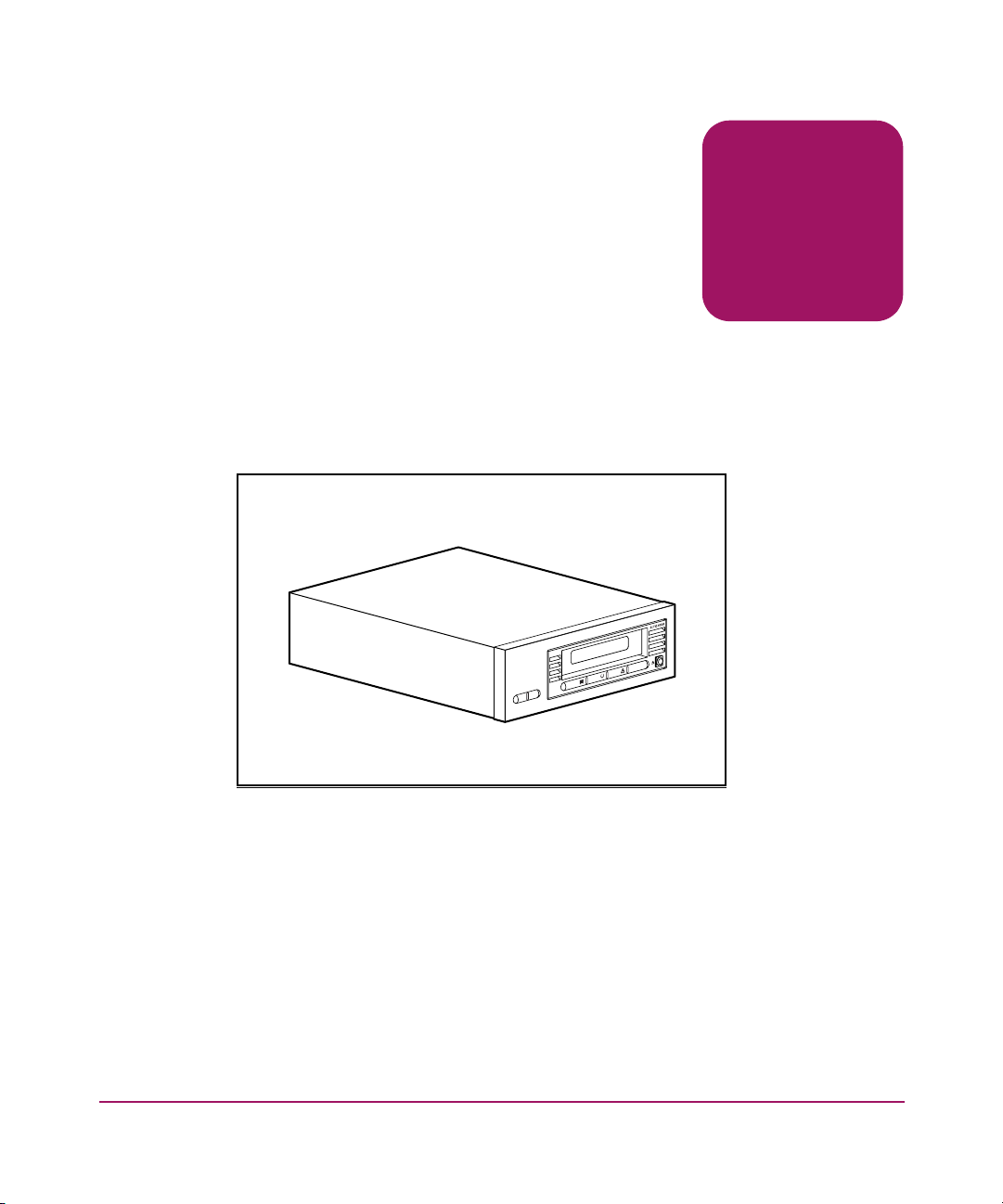
The HP StorageWorks DLT VS80 Tape Drive is a value-priced, high-capacity
streaming cartridge tape drive designed for use with HP systems. The drive has a
dual-channel read/write head, Lempel-Ziv (DLZ) high-efficiency data
compression, and tape-mark directory to achieve fast data throughput and access
times.
1
Figure 1: DLT VS80 tape drive
Previously Recorded Media
The DLT VS80 can read DLTtape™IV media previously recorded using a DLT
20/40 format. The DLT VS80 can only write to brand new DLTtapeIV media or
media previously recorded using a DLT I or DLT VS80 tape drive. See “Using
Cartridges” in Chapter 5 for additional information.
13DLT VS80 Tape Drive Reference Guide
Page 14

Introduction
Software Included
The DLT VS80 tape drive ships with a CD that contains Microsoft certified
drivers that support the Microsoft Windows NT, Windows 2000, or Windows
Advanced Server 2003 operating systems. Multiple software utilities are also
available to customers through the HP website and can be downloaded free of
charge.
System Requirements
Your DLT VS80 tape drive requires a wide, SCSI-2, Low Voltage Differential
(LVD) or Single-Ended (SE) SCSI bus. The following controller types are
supported:
■ Fast SCSI-2 (Wide)
■ Wide-Ultra SCSI
■ Ultra2 SCSI
■ Ultra3 SCSI
Note: The DLT VS80 tape drive does not support High Voltage Differential (HVD)
controllers.
Install and configure the controller before beginning the drive installation, using
the documentation included with the controller. If you connect your DLT VS80
tape drive to an SE SCSI bus, drive performance is limited to the maximum data
transfer speed of the SE bus.
If connected to an Ultra2 or Ultra3 controller, data transfer is limited to the
maximum transfer rate of the Wide-Ultra interface on the DLT VS80 tape drive.
14 DLT VS80 Tape Drive Reference Guide
Page 15

Data Compression
The DLT VS80 tape drive offers a formatted, native cartridge capacity of 40 GB
(80 GB assuming a 2:1 compression ratio) and a sustained user data transfer rate
of 3 MB/s (up to 6 MB/s with 2:1 compression).
Note: Capacity may vary based upon actual stored data. Data transfer rate can vary
depending on actual data.
The DLT VS80 tape drive ships from the factory with data compression enabled
for writing. In this mode, data is always compressed when writing to the tape, but
the drive is capable of reading both compressed and uncompressed tapes. For the
drive to write uncompressed data, the data compression setting must be changed
through the software. To change it, consult the backup application software
documentation for the data compression enabling and disabling procedure.
Introduction
15DLT VS80 Tape Drive Reference Guide
Page 16

Introduction
16 DLT VS80 Tape Drive Reference Guide
Page 17

External Tape Drive Installation
Installing the DLT VS80 external tape drive requires no special tools. You will
need a ballpoint pen to change the SCSI ID switch on the rear panel of the drive.
WARNING: Risk of electric shock. Do not attempt to open this product. There
are no user-serviceable parts inside. Refer all service to an HP authorized
service provider.
Installation Overview
1. Unpack the drive and check for shipping damage.
2. Select a location near the server that is to be the host for the DLT VS80 tape
drive.
3. Set the SCSI ID, if necessary.
4. Shut down and turn off the server that is to host the tape drive. Remove the
power cable from the selected server. Turn off and remove the power cables
from all devices attached to the selected server.
5. Install an LVD/SE SCSI host adapter in the server that is to be the host for the
drive, if necessary.
2
6. Attach the SCSI cable to the tape drive and SCSI host adapter.
7. Install the terminator on the tape drive if it is the last or only device on the
SCSI bus.
8. Attach the power cables to the tape drive, server, and all attached devices.
Plug in the power cable to the nearest power outlet, and turn on all devices.
9. Install software drivers, if necessary.
10. Verify that the tape drive is working properly.
17DLT VS80 Tape Drive Reference Guide
Page 18

External Tape Drive Installation
Unpacking the Tape Drive
Caution: If the room where you are unpacking the drive differs from the
temperature at which the tape drive was shipped or stored by 30º F (15º C) or
more, let the drive acclimate to the surrounding environment for at least 12
hours before opening the shipping carton.
Unpack and inspect the tape drive for shipping damage:
1. Inspect the shipping box for damage. If you notice any damage, report it to the
shipping company immediately.
2. Open the shipping box and remove the accessories package. Open the
accessories package; you will need these items during installation.
3. With the drive still in the shipping box, reach under and around the drive.
Carefully lift it out of the shipping box and place it on the work surface, top
facing up. Do not stand the drive on either end.
4. Carefully remove the drive from the protective bag.
Note: Save the packing materials in case you need to move or ship the drive in the
future. You must ship the DLT VS80 tape drive in the original or equivalent packing
materials to preserve your warranty.
18 DLT VS80 Tape Drive Reference Guide
Page 19

Selecting an Installation Location
Select an installation location that is flat, sturdy, level, and close to the host server.
A desk or table top is most suitable. Regardless of the location you choose for the
external DLT VS80 tape drive, make sure the environment is free from dust and
excessive temperature and humidity. See Appendix C, “Specifications,” for
acceptable operating temperature and humidity limits.
Be sure to follow these additional guidelines:
■ Allow at least 6 inches (15.3 cm) behind the drive for proper cooling.
■ Avoid locations near printers or photocopy machines, both of which produce
paper fiber and other types of dust and airborne contaminants.
■ Do not place your drive on the floor.
■ Avoid locations near generators, electric motors, audio speakers, or other
sources of magnetic fields. Magnetic fields can adversely affect your drive
and media.
External Tape Drive Installation
19DLT VS80 Tape Drive Reference Guide
Page 20
External Tape Drive Installation
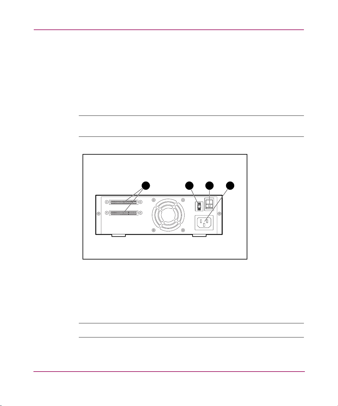
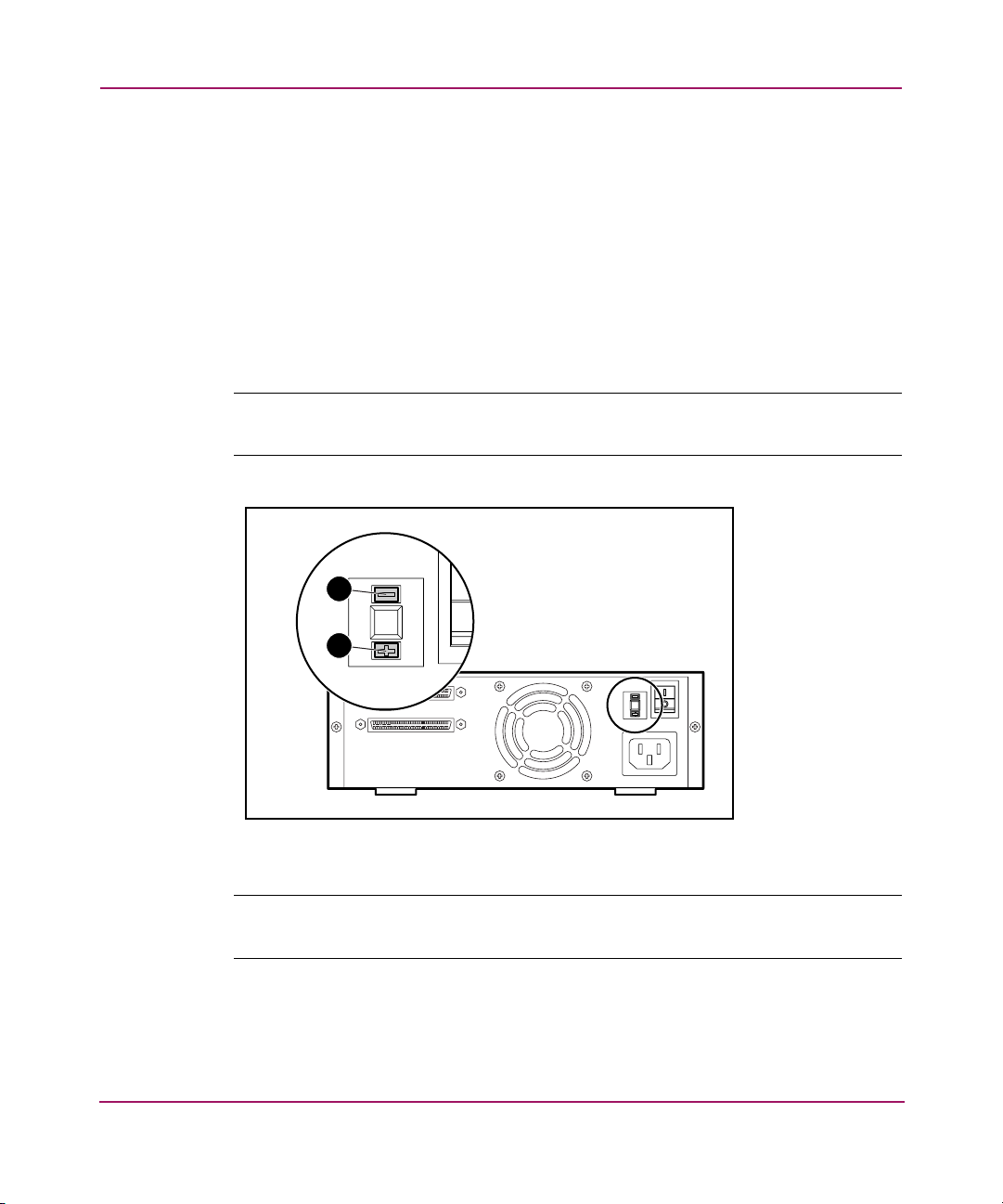
Setting the SCSI ID
Each SCSI device attached to the server that is to be the host for the DLT VS80
tape drive must have a unique SCSI ID. Check the SCSI IDs on all other devices
attached to the selected SCSI bus, including the SCSI host adapter itself, on the
selected server and select an unused SCSI ID for the tape drive. If the drive factory
default SCSI ID 6 is not being used by another device on the same SCSI bus, you
do not need to change the SCSI ID.
Note: You can use Library and Tape Tools (L&TT) to check the SCSI IDs on the other
devices. See Chapter 6, “Troubleshooting,” for complete information on L&TT.
1 2 3 4
Figure 2: Rear view of tape drive
1 68-pin SCSI connectors
2 SCSI ID display
3 Power switch
4 Power cable connector
Note: If the tape drive is attached to a narrow SCSI bus, only IDs 0 through 7 are valid.
20 DLT VS80 Tape Drive Reference Guide
Page 21
External Tape Drive Installation
To set the SCSI ID use a small screwdriver or ballpoint pen to press the button
above or below the SCSI ID display.
■ Press the button above the SCSI ID display 1 to select the next lower SCSI
ID.
■ Press the button below the SCSI ID display 2 to select the next higher SCSI
ID.
Each time you press one of these buttons, the SCSI ID decreases or increases by
one. Press the appropriate button until the desired SCSI ID appears on the switch
display.
Note: SCSI ID 7 is reserved for the controller. The SCSI ID can be set up to 15, but a
SCSI ID above 6 is not recommended.
1
2
Figure 3: SCSI ID switch
Note: If the drive is powered on when you change the SCSI ID, you must power the
drive off and on again for the new SCSI ID to take effect.
21DLT VS80 Tape Drive Reference Guide
Page 22

External Tape Drive Installation
Connecting a Single Drive
If the selected server does not already have an LVD/SE SCSI host adapter
installed, install one now.
To connect the SCSI and power cables:
1. Shut down the operating system and power off the selected server. Turn off all
attached peripherals such as printers and other SCSI devices. Remove the
power cable from the host server and all attached peripherals.
Caution: Failure to follow these instructions could result in damage to the DLT
VS80 tape drive or other devices.
2. Remove the SCSI cable from the accessories package and locate the external
SCSI port on the rear of the server.
Note: The SCSI cable included with the DLT VS80 tape drive allows connection to a
68-pin VHDCI HBA, which will accommodate most servers. If your HBA does not have
a 68-pin VHDCI connector, you will need to purchase a separate cable. Refer to the
Quick Specs at
http://www.hp.com
for cable option part numbers.
Note: Your server may differ from the following illustrations; refer to the documentation
included with your server.
22 DLT VS80 Tape Drive Reference Guide
Page 23
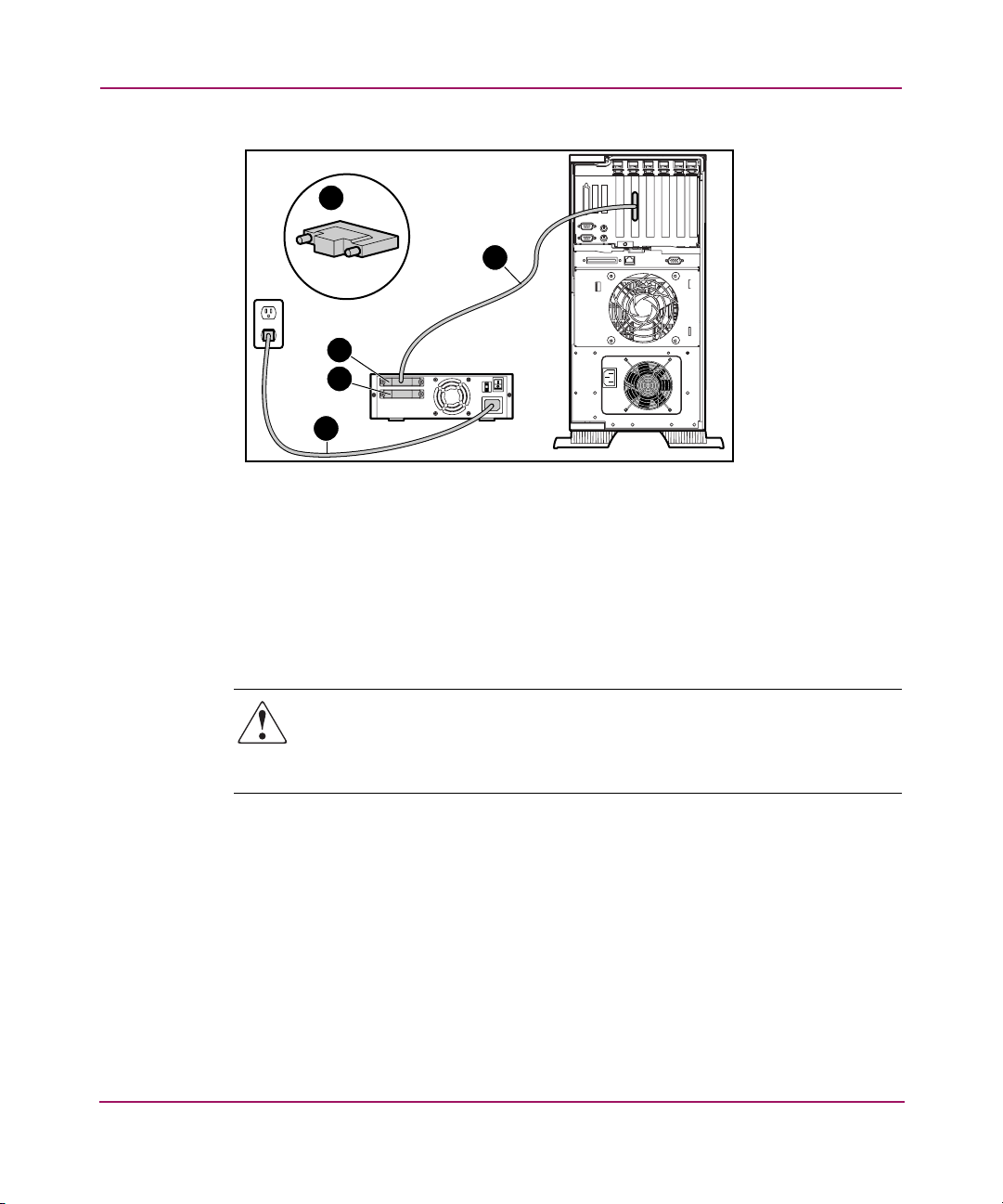
External Tape Drive Installation
3
1
2
3
4
Figure 4: Connecting a single external drive
3. Attach the SCSI signal cable 1 to the SCSI connector 2 location on the rear
panel of the DLT VS80 tape drive and then to the external SCSI-2 port on the
server.
4. Tighten the thumbscrews to secure the cable to the connector.
5. Attach the terminator 3 to the SCSI connector.
WARNING: To reduce the risk of electric shock or damage to your equipment,
do not disable the power cord grounding feature. This equipment is designed
for connection to a grounded (earthed) power outlet. The grounding plug is an
important safety feature.
6. Plug the drive AC power cord 4 into the drive, then into a grounded AC
outlet.
7. Plug in the AC power cords for any remaining peripheral devices and power
all of them on.
8. Plug in the AC power cord for the server and power it on.
See Figure 5 if you want to daisy-chain several drives.
23DLT VS80 Tape Drive Reference Guide
Page 24

External Tape Drive Installation
Note: To daisy-chain, you must purchase additional cables. Refer to the Quick Specs at
http://www.hp.com
1
2
Figure 5: Daisy-chaining several external drives
for cable option part numbers.
1 To SCSI host adapter
2 Terminator
Note: Each tape drive in the daisy-chain must have a unique SCSI ID. See “Setting the
SCSI ID” in this chapter.
24 DLT VS80 Tape Drive Reference Guide
Page 25

Terminating the Tape Drive
If the DLT VS80 tape drive is the only SCSI device – other than the SCSI host
adapter – on the selected server, it must be terminated. Likewise, if the DLT VS80
tape drive is the last device on the selected server SCSI bus, it must be terminated.
If the DLT VS80 tape drive is at the end of the SCSI cable, it is the last device on
the SCSI bus.
To terminate the DLT VS80 tape drive, locate the terminator in the accessories
package and press it firmly into either of the two SCSI connectors on the rear
panel of the drive. Secure the terminator by tightening the screws until snug.
1
2
2
External Tape Drive Installation
Figure 6: Terminating the tape drive
1 To SCSI host adapter
2 Terminator
25DLT VS80 Tape Drive Reference Guide
Page 26

External Tape Drive Installation
Verifying the Tape Drive Installation
Every time the DLT VS80 tape drive is powered on, it conducts a Power-On
Self-Test (POST) to ensure that the drive is working properly and ready to use.
While POST is in progress, watch the front panel LEDs to see the progress and
results of the test. During POST, the following actions take place:
1. The LEDs turn on all at once and then turn off.
2. The Ready (green) LED blinks during initialization and remains illuminated
after POST.
3. The drive emits a buzzing sound as the drive calibrates the read/write head's
position.
POST is complete only after the buzzing sound stops. POST takes several seconds
to complete.
Using Library and Tape Drive Tools to Verify Physical Installation
You can use the HP Library and Tape Tools (L&TT) to verify the physical
installaion of the tape drive. Complete instructions and download of L&TT are
available at:
http://www.hp.com/support/tapetools
Completing the Installation
You may need to install a device driver for your operating system to correctly
communicate with your tape device. Proceed to Chapter 4, “Operating System
Device Drivers.”
26 DLT VS80 Tape Drive Reference Guide
Page 27

Internal Tape Drive Installation
The following items may be required for DLT VS80 tape drive installation:
■ Torx T-15 screwdriver
■ Type 1A, Phillips screwdriver
Installation Overview
1. Unpack the drive and check for shipping damage.
2. Select a server that is to be the host for the DLT VS80 tape drive.
3. Set the SCSI ID, if necessary.
4. Shut down and turn off the server that is to host to the tape drive. Remove the
power cable from the selected server. Turn off and remove the power cables
from all devices attached to the selected server.
5. Remove the cover from the selected server as explained in the server manuals.
6. Install an LVD/SE SCSI host adapter in the server that is to be the host for the
drive, if necessary.
7. If necessary, attach the drive rails that ship with the drive.
3
Note: Your server may supply rails in the drive bay. Refer to your server user guide for
information on the correct rails to use with your server.
8. Install the DLT VS80 tape drive into an open drive bay.
9. Attach the SCSI ribbon cable to the tape drive and SCSI host adapter.
10. If necessary, install a terminator on the SCSI ribbon cable if the tape drive is
the last or only device on the SCSI bus.
11. Attach a power cable to the internal DLT VS80 tape drive.
27DLT VS80 Tape Drive Reference Guide
Page 28

Internal Tape Drive Installation
12. Secure the tape drive in the selected server.
13. Replace the server cover, attach power cables to all devices, power on the
server and other devices.
14. Install software drivers, if necessary.
15. Verify that the tape drive is working properly.
Unpacking the Tape Drive
Caution: If the room where you are unpacking the drive differs from the
temperature at which the tape drive was shipped or stored by 30º F (15º C) or
more, let the drive acclimate to the surrounding environment for at least 12
hours before opening the shipping carton.
Unpack and inspect the tape drive for shipping damage:
1. Inspect the shipping box for damage. If you notice any damage, report it to the
shipping company immediately.
2. Open the shipping box and remove the accessories package. Open the
accessories package; you will need these items during installation.
3. With the drive still in the shipping box, reach under and around the drive.
Carefully lift it out of the shipping box and place it on the work surface, top
facing up. Do not stand the drive on either end.
4. Carefully remove the drive from the protective bag.
Note: Save the packing materials in case you need to move or ship the drive in the
future. You must ship the DLT VS80 tape drive in the original or equivalent packing
materials to preserve your warranty.
28 DLT VS80 Tape Drive Reference Guide
Page 29

Setting the SCSI ID
Each SCSI device attached to the server that is to be the host for the DLT VS80
tape drive must have a unique SCSI ID. Check the SCSI IDs on all other devices
attached to the selected SCSI bus, including the SCSI host adapter itself, on the
selected server and select an unused SCSI ID for the tape drive. If the drive factory
default SCSI ID 6 is not being used by another device on the same SCSI bus, you
do not need to change the SCSI ID.
Note: You can use Library and Tape Tools (L&TT) to check the SCSI IDs on the other
devices. See Chapter 6, “Troubleshooting,” for complete information on L&TT.
Internal Tape Drive Installation
1 2 3
Figure 7: Rear view of internal tape drive
1 68-pin SCSI connector
2 Power connector
3 SCSI ID jumpers
Note: If the tape drive is attached to a narrow SCSI bus, only IDs 0 through 7 are valid.
29DLT VS80 Tape Drive Reference Guide
Page 30

Internal Tape Drive Installation
Locate the SCSI ID jumpers on the rear panel of the drive as shown in Figure 7.
Use Figure 8 to select the desired SCSI ID.
SCSI ID 0 1 2 3 4 5 6
Jumper
Block
Figure 8: SCSI ID settings
Note: SCSI ID 7 is reserved for the controller. The SCSI ID can be set up to 15, but a SCSI ID
above 6 is not recommended.
Terminating the Tape Drive
If the DLT VS80 tape drive is the only SCSI device – other than the SCSI host
adapter – on the selected server, it must be terminated. Likewise, if the DLT VS80
tape drive is the last device on the selected server SCSI bus, it must be terminated.
The DLT VS80 tape drive ships with a ribbon cable that is already terminated as
shown in Figure 9. If you use a cable other than the one provided, be sure that the
cable is terminated at each end.
30 DLT VS80 Tape Drive Reference Guide
Page 31

Figure 9: Ribbon cable with terminator
Installing the Internal Tape Drive
Internal Tape Drive Installation
Caution: Electrostatic discharge (ESD) can damage electronic components. Be
sure you are properly grounded before beginning this procedure. See
Appendix B, “Electrostatic Discharge,” for additional information.
1. Shut down the operating system and power off the selected server. Turn off all
attached peripherals such as printers and other SCSI devices. Remove the
power cable from the host server and all attached peripherals.
Caution: Failure to follow these instructions could result in damage to the DLT
VS80 tape drive or other devices.
2. Remove the cover from the host server to allow access to the desired drive
bay.
31DLT VS80 Tape Drive Reference Guide
Page 32

Internal Tape Drive Installation
Note: Your server may differ from the following illustrations; refer to the documentation
included with your server.
Figure 10: Installing an internal drive
T
C
E
L
E
S
T
C
E
J
E
R
E
T
N
E
3. Install an LVD/SE SCSI host adapter in the server that is to be the host for the
drive, if necessary.
4. If necessary, attach the drive rails that ship with the drive.
Note: You may need to use the rails that ship with your server. Refer to your server user
guide for information on the correct rails to use.
5. Insert the drive into an available 5 1/4-inch drive bay.
Note: You may need to remove the front cover from the drive bay. Refer to the
documentation included with your server.
6. Secure the tape drive into the server according to the documentation included
with the server.
7. Connect an available power cable and the wide SCSI signal cable.
32 DLT VS80 Tape Drive Reference Guide
Page 33

Internal Tape Drive Installation
1
2
Figure 11: Connecting the power and signal cable
1 Signal cable
2 Power cable
8. Attach the other end of the SCSI ribbon cable to the SCSI host adapter.
9. Replace the cover on the server.
10. Plug in the AC power cords for any peripheral devices and power all of
them on.
11. Plug in the AC power cord for the server and power it on.
33DLT VS80 Tape Drive Reference Guide
Page 34

Internal Tape Drive Installation
Verifying the Tape Drive Installation
Every time the DLT VS80 tape drive is powered on, it conducts a Power-On
Self-Test (POST) to ensure that the drive is working properly and ready to use.
While POST is in progress, watch the front panel LEDs to see the progress and
results of the test. During POST, the following actions take place:
1. The LEDs turn on all at once and then turn off.
2. The Ready (green) LED blinks during initialization and remains illuminated
after POST.
3. The drive emits a buzzing sound as the drive calibrates the read/write head's
position.
POST is complete only after the buzzing sound stops. POST takes several seconds
to complete, after which the drive is ready to use.
Using Library and Tape Drive Tools to Verify Physical Installation
You can use the HP Library and Tape Tools (L&TT) to verify the physical
installaion of the tape drive. Complete instructions and download of L&TT are
available at:
http://www.hp.com/support/tapetools
Completing the Installation
You may need to install a device driver for your operating system to correctly
communicate with your tape device. Proceed to Chapter 4, “Operating System
Device Drivers.”
You can use the HP Library and Tape Tools (L&TT) to verify the physical
installaion of the tape drive. Complete instructions and download of L&TT are
available at:
http://www.hp.com/support/tapetools
34 DLT VS80 Tape Drive Reference Guide
Page 35

Operating System Device Drivers
The following operating systems support the HP StorageWorks DLT VS80 tape
drive:
■ Microsoft® Windows NT 4.0
■ Microsoft Windows 2000
■ Microsoft Windows Advanced Server 2003
■ Novell NetWare
■ HP Tru64 UNIX
■ Red Hat Linux
■ SuSe Linux
For an updated list of supported operating systems, refer to:
http://www .hp.com.
Device Drivers
Windows Operating System device drivers for Intel-based systems are available
on the documentation CD that shipped with your product or can be downloaded
from the HP website.
4
To download the drivers from the HP website go to:
http://welcome.hp.com/cou ntry/us/eng/software_drivers.htm
1. Type DLT VS80 in the enter product model number field.
2. Select the HP StorageWorks DLT VS80 tape drive.
3. Select your operating system.
4. Download the driver for the HP StorageWorks DLT VS80 tape drive.
35DLT VS80 Tape Drive Reference Guide
Page 36

Operating System Device Drivers
Installing Drivers on Windows NT 4.0
These instructions apply to the Windows NT Backup Utility and other
applications that don't provide their own drivers.
Note: Before starting the driver installation, verify that your tape drive is properly
connected. Windows NT 4.0 only allows you to install tape device drivers sequentially.
If you have other tape devices installed without drivers, install those drivers before
attempting the following procedure, or click Cancel to bypass each tape device.
1. Click Start > Settings > Control Panel to open the Windows Control Panel.
2. Double-click the Tape Devices icon.
3. The Tape Devices dialog box is displayed and indicates that the driver for the
new tape drive is not loaded. If the system does not automatically scan for
new devices, select Detect. This scanning process creates a list of device
drivers available for installation.
4. In the Install Driver dialog box, click Have Disk. The Install From Disk dialog
box is displayed.
5. In the Copy manufacturer's files from field, type the driver path as shown
below, and then select OK. Substitute the correct drive letter for your CD
ROM drive.
For Intel systems:
E:drivers\nt4\
6. In the Install Driver dialog box, select the appropriate driver for your tape
drive and click OK.
7. In the New SCSI Tape Device Found dialog box, click OK.
8. In the Tape Devices dialog box, click OK. This step completes the driver
installation. Remove the CD and restart your system.
36 DLT VS80 Tape Drive Reference Guide
Page 37

Installing Drivers on Windows 2000
These instructions apply to the Windows Backup Utility.
1. Right-click the My Computer icon and select Manage.
2. Select Device Manager on the left panel to display all the devices on the right
panel on the Computer Management console. Make all subsequent selections
from the devices shown in the right panel.
3. If the tape drive has not yet been installed, connect the device and select Scan
for hardware changes to detect the device. At first, the device might be
displayed in the “other device” category under the ? icon. After the correct
driver is installed the device will be correctly displayed in the tape drives
category.
To install the DLT VS80 tape driver, select the tape drive under device manager
and do the following:
1. Right click the drive and select Properties.
2. Select the Driver tab.
3. Click Update Driver to launch the Update Device Driver Wizard.
4. When prompted, select the option to display a list of known drivers.
5. Click Have Disk and select the CD ROM drive.
Operating System Device Drivers
6. Navigate to the \Drivers\win2000 directory.
7. Select the .inf file and click OK.
8. The wizard displays a list of the drives available in this directory.
9. Select the item that describes your drive and then click OK to install the
driver.
37DLT VS80 Tape Drive Reference Guide
Page 38

Operating System Device Drivers
Installing Drivers on Advanced Server 2003
These instructions apply to the Windows Backup Utility.
1. Right-click the My Computer icon and select Manage.
2. Right-click on the device in the list and select Update Driver.
3. If the tape drive has not yet been installed, connect the device and select Scan
for hardware changes to detect the device. At first, the device might be
displayed in the “other device” category under the ? icon. After the correct
driver is installed the device will be correctly displayed in the tape drives
category.
4. When prompted, select the option to display a list of known drivers.
5. Click Have Disk and select the CD ROM drive.
6. Navigate to the \Drivers\AS2003 directory.
7. Select the .inf file and click OK.
8. The wizard displays a list of the drives available in this directory.
9. Select the item that describes your drive and then click OK to install the
driver.
38 DLT VS80 Tape Drive Reference Guide
Page 39

Novell NetWare
The tape device driver is located with the operating system. Refer to the backup
application installation guide for more information regarding additional software
that might be needed.
Table 2 provides a list of supported controllers and where to get information about
the software driver:
Table 2: Novell NetWare
Wide-Ultra SCSI
Ultra-2 SCSI
Be sure to load the appropriate drivers in accordance with the controller being
used. There are additional driver considerations if you want to use applications
requiring the Advanced SCSI Programming Interface (ASPI) support. For more
information, see the “ASPI Support” section.
ASPI Support
Operating System Device Drivers
Controller Software Driver Information
Run the
Software Support Diskettes (NSSD) for driver
installation instructions.
Readme.com
file on any of the Novell
The Readme.com file on the Novell Software Support Diskette (NSSD) outlines
the specific drivers you need to support ASPI tape backup applications.
If you are using a tape backup application that uses ASPI, such as ARCserve
provided by Computer Associates or VERITAS BackupExec, refer to the
information provided with the application NLM to determine whether it uses
ASPI.
The ASPI drivers, Cpqsaspi.nlm Device Driver Functional Specification (DDFS)
and Nwaspi.nlm NetWare Peripheral Architecture (NWPA), provide ASPI support
for the SCSI architecture for applications that require this interface.
Note: Some ISPs such as VERITAS use their own ASPI drivers. Please read the ISV
documentation before loading nwaspi.
All required drivers for ASPI tape support are provided on the NSSD. The NSSD
ships with each server or can be downloaded from the HP website at:
http://welcome.hp.com/cou ntry/us/eng/software_drivers.htm
The Scsi.rdm file on the NSSD gives complete instructions on how to load these
drivers and troubleshoot any problems.
39DLT VS80 Tape Drive Reference Guide
Page 40

Operating System Device Drivers
HP Tru64 UNIX
The HP Tru64 UNIX operating system uses Dynamic Device Recognition (DDR)
which allows the operating system to recognize the DLT VS80 tape drive.
If the Tru64 UNIX system does not have a DDR entry to identify the DLT VS80
tape drive, the system defaults to a generic SCSI device and to the default settings
of the tape drive.
DDR Recognition
Note: Starting with UNIX 5.1, the syntax for tape related commands changed. The
examples included below show the new syntax.
The DLT VS80 tape drive provides compression so that the storage capability for
tapes can be effectively be doubled. This is known as hardware compression.
Hardware compression should be used instead of the software compression, which
is sometimes provided by software products. The drive is instructed by the user to
turn off hardware compression through use of switches in utilities such as tar.
(Additional information is available online. See the man pages for tz, file,
tar, dump and cpio. Additionally the man page for ddr.dbase can be useful. It
is the derivation for the integers associated with compression below).
The drive defaults to implement hardware compression. In some very limited
cases the drive performance can be improved by turning off hardware
compression.
40 DLT VS80 Tape Drive Reference Guide
Page 41

Turning Compression On or Off
The following sections give two examples of turning compression on or off using
the tar command.
Example 1 - Turning Compression On
An example to turn on compression using a tar command is:
$tar cvf /dev/tape/tape5_d? filename.txt
Where:
■ tape5 = the tape device as known by the system (shown in the file command,
in this case, tape unit 5).
■ ? = 1, 3, 5 or 7 will turn hardware compression on.
Example 2 - Turning Compression Off
The following command turns hardware compression off:
$tar cvf /dev/tape/tape5 filename.txt
Where:
■ tape5 = the tape device as known by the system (shown in the file command,
in this case, tape unit 5).
Operating System Device Drivers
■ ? = 0, 2, 4 or 6 will turn hardware compression off (see the DLT VS80 drive
description in the ddr.dbase file online).
DDR tables are part of the UNIX patches. For the latest UNIX patches refer to:
http://welcome.hp.com/cou ntry/us/eng/software_drivers.htm.
41DLT VS80 Tape Drive Reference Guide
Page 42

Operating System Device Drivers
Red Hat Linux
Red Hat Linux provides native drive recognition. Drive files are located in the /dev
directory. Supplemental drivers are not required. The operating system defaults to
a generic SCSI device and to the default settings of the tape drive.
Table 3: Typical Native OS Commands
Task Command
Tar Write tar cvf /dev/st0 ./largefile
Tar Read tar xvf /dev/st0
DD Write dd if=./largefile of=//dev/st0 bs=51
DD Read dd if=//dev/st0 of=./largefile bs=512
SuSe Linux
SuSe Linux provides native drive recognition. Drive files are located in the /dev
directory. Supplemental drivers are not required. The operating system defaults to
a generic SCSI device and to the default settings of the tape drive.
Table 4: Typical Native OS Commands
Task Command
Tar Write tar cvf /dev/st0 ./largefile
Tar Read tar xvf /dev/st0
DD Write dd if=./largefile of=/dev/st0 bs=512
DD Read dd if=/dev/st0 of=./largefile bs=512
42 DLT VS80 Tape Drive Reference Guide
Page 43

Operating the DLT VS80 Tape Drive
This chapter describes:
■ Front Panel Controls and Indicators
■ Using Cartridges
— Inserting a cartridge
— Removing a cartridge
— Write-Protecting a cartridge
— Caring for cartridges
— Using the cleaning cartridge
5
43DLT VS80 Tape Drive Reference Guide
Page 44

Operating the DLT VS80 Tape Drive
Front Panel Controls and Indicators
Every time the DLT VS80 tape drive is powered on, it conducts a Power-On
Self-Test (POST) to ensure that the drive is working properly and ready to use.
While POST is in progress, watch the front panel LEDs to see the progress and
results of the test. During POST, the following actions take place:
1. The LEDs turn on all at once and then turn off.
2. The Ready (green) LED blinks during initialization and remains illuminated
after POST.
3. The drive emits a buzzing sound as the drive calibrates the read/write head's
position.
POST is complete only after the buzzing sound stops. POST takes several seconds
to complete, after which the drive is ready to use.
1 2 3 4 5 6
Figure 12: Front panel components
1 External power LED 4 Clean/Media LED
2 Drive error LED 5 Cartridge door
3 Ready LED 6 Unload button
44 DLT VS80 Tape Drive Reference Guide
Page 45

Operating the DLT VS80 Tape Drive
Tabl e 5 describes the meaning of the front panel LEDs.
Table 5: Indicator Activity
Indicator State Operating Condition
Drive error (amber) Blinking An unrecoverable drive error or a
POST error has occurred. Call
Technical Support.
Off No drive errors.
Ready (green) On Power to the drive.
Off No power to the drive.
Blinking (constant
period & duty cycle)
Clean/Media (amber) Blinking
Off Cleaning is not required.
All three LEDs On POST is starting.
Blinking Firmware upgrade in progress.
External power LED On Power to the drive.
Off No power to the drive.
Tape is in motion.
■ A hard read/write error that
is probably recoverable has
occurred. Clean the drive.
The LED is off after
completing a cleaning cycle
with a DLT1/DLT VS
Cleaning Cartridge after
loading a properly formatted
data cartridge into the drive.
Cycling the power on the
drive also turns off the LED.
■ An inappropriate tape has
been loaded into the drive.
The tape should
automatically eject.
■ The drive has exceeded 150
tape motion hours. The drive
must be cleaned. Cycling the
power on the drive does not
turn off the LED.
45DLT VS80 Tape Drive Reference Guide
Page 46

Operating the DLT VS80 Tape Drive
Using Cartridges
The DLT VS80 tape drive uses only DLTtape™IV cartridges. The DLT VS80 tape
drive automatically unloads any other cartridge types and any cartridges whose
format it cannot read. Make sure all cartridges that you want to use for writing are
either unformatted or have been formatted with the DLT VS80 tape drive before
loading them.
The DLT VS80 tape drive can use previously written media that has been
degaussed. DLTtape™IV media is rated at 1850 oersteds. Typical handheld
degaussers do not have the rating to completely degauss DLTtape™IV media. To
completely degauss, the degausser used must be rated at at least 1850 oersteds,
although a value two to three times greater than 1850 oersteds is preferred.
Note: If you use an outside vendor to degauss your media, be sure their equipment
meets this criteria.
The DLT VS80 tape drive can read (but not write to) DLTtape™IV cartridges that
have been written using a DLT 20/40 tape drive.
Table 6: Media Compatibility
DLT VS80 Can
Cartridge
DLTtape IV written to by DLT VS80 Yes Yes
DLTtape IV written to by DLT1 Yes Yes
DLTtape IV written to by DLT 20/40 Yes No
DLTtape IV written to by DLT 35/70 No No
DLTtape IV written to by DLT 40/80 No No
DLTtape III No No
46 DLT VS80 Tape Drive Reference Guide
Read
DLT VS80 Can
Write
Page 47

Inserting a Cartridge
To load a cartridge into the DLT VS80 tape drive:
1. Insert the DLTtape IV cartridge into the cartridge slot after the drive
completes POST. See Figure 13.
2. Gently push the cartridge into the drive until it stops.
Operating the DLT VS80 Tape Drive
Figure 13: Inserting a DLTtape IV cartridge
47DLT VS80 Tape Drive Reference Guide
Page 48

Operating the DLT VS80 Tape Drive
Removing a Cartridge
Caution: To avoid damage to the cartridge or the tape drive, remove the
cartridge from the DLT VS80 tape drive before turning off the drive. Leaving a
cartridge in the drive when power is off can result in cartridge and drive
damage and may cause data loss because the header/catalog data may not
be properly written before the drive loses power.
To remove a cartridge:
1. Press the Unload button or use the backup software to unload the cartridge.
The Ready LED blinks while the drive rewinds the tape. When the drive has
rewound the tape it ejects the cartridge.
2. Remove the cartridge from the drive.
Figure 14: Removing a DLTtape IV cartridge
3. Return the cartridge to its storage case.
48 DLT VS80 Tape Drive Reference Guide
Page 49

Write-Protecting a Cartridge
All DLTtape IV cartridges have a write-protect switch to prevent accidental
erasure of data. Before loading the cartridge into the drive, position the
write-protect switch on the front of the cartridge. By moving the switch to the left
1, the cartridge is write-protected. By moving the switch to the right 2, the
cartridge is write-enabled.
Operating the DLT VS80 Tape Drive
1
2
Figure 15: Cartridge write-protect switch
Caring for Cartridges
To ensure longer life of recorded or unrecorded cartridges, follow these
guidelines:
■ Use cartridges in temperatures between 16ºC and 32ºC (60.8ºF to 89.6ºF).
When stored at these conditions cartridges have a life expectancy of 20 years.
■ Do not expose cartridges to direct sunlight or sources of heat, including
portable heaters and heating ducts.
■ If the cartridge has been exposed to extreme heat or cold, stabilize the
cartridge at room temperature for the same amount of time it was exposed —
up to 24 hours.
■ Do not place cartridges near electromagnetic interference sources, such as
terminals, motors, and video or X-ray equipment. Data on the cartridge can be
altered.
49DLT VS80 Tape Drive Reference Guide
Page 50

Operating the DLT VS80 Tape Drive
■ Store cartridges in a dust-free environment where the relative humidity is
between 20% and 80% (noncondensing). For longer cartridge life, store the
cartridge at 20% to 80% relative humidity.
■ Store cartridges in their storage cases.
■ Do not drop or strike a cartridge. Excessive shock can displace the tape leader,
making the cartridge unusable and possibly damaging your DLT VS80 tape
drive.
■ Place identification labels only in the slide-in slot on the front of the cartridge.
■ Never use any type of adhesive labels on the cartridges.
■ Never stack cartridges more than five high.
Condensation
Condensation can be a problem for tape drives and cartridges. To minimize the
chance of condensation, stay within the specifications above for using and storing
cartridges and observe the following guidelines:
■ Position the drive where the temperature is relatively stable - away from open
windows, heat sources, and doors.
■ Avoid leaving cartridges in severe temperature conditions, for example, in a
car standing in bright sunlight.
■ Avoid transferring data (reading from and writing to cartridges) when the
temperature is changing by more than 10ºC (18ºF) per hour.
■ If you bring a cold tape drive or cartridge into a warm room, allow time for it
to warm to room temperature before using it. For example, if you have moved
the drive from a cold car to a warm room, allow time for the drive to reach
room temperature (up to 24 hours if the temperature change is extreme.)
50 DLT VS80 Tape Drive Reference Guide
Page 51

Using the Cleaning Cartridge
When the Clean/Media LED is on, the DLT VS80 tape drive read/write head may
need to be cleaned.
Insert the cleaning cartridge as you would a data cartridge. See “Inserting a
Cartridge.” Cleaning typically takes several minutes during which the Ready LED
blinks.
You should only use DLT 1/DLT VS Cleaning Cartridges, which are a smoky-gray
color. Inappropriate cleaning tapes are immediately ejected.
Caution: Do not use a DLT Cleaning Tape III, which is a cream color
(p/n 199704-001 or C5142A).
Use only HP-approved DLT 1/DLT VS Cleaning Cartridges (p/n 279839-B21
or C7998A). Use of any other type of cleaning cartridge can damage the tape
drive read/write head.
Each cleaning cartridge has a useful life of 20 cleanings. The cleaning cartridge
includes a label with 20 small boxes printed on it. Always place a check mark in a
box each time you use the cartridge to clean the drive. Replace the cleaning
cartridge when all boxes are checked.
When the cleaning cartridge has cleaned the read/write head, the Clean/Media
LED turns off and the drive ejects the cleaning cartridge.
Operating the DLT VS80 Tape Drive
Note: If any LEDs blink or if the Clean/Media LED is illuminated again when you
insert another cartridge immediately after cleaning, see Table 5 for more information.
Proceed to the trouble shooting section in Chapter 6, if necessary.
51DLT VS80 Tape Drive Reference Guide
Page 52

Operating the DLT VS80 Tape Drive
52 DLT VS80 Tape Drive Reference Guide
Page 53

Troubleshooting and Upgrading the Firmware
Troubleshooting
The HP Library and Tape Tool (L&TT) is a tape management and diagnostic tool.
In addition to the diagnostic and troubleshooting ability of L&TT, it offers useful
information about your products and provides automated firmware update checks
from the Internet, with the ability to retrieve the latest firmware versions.
Use L&TT to perform a first level failure analysis. If you are unable to solve the
issue by running L&TT and referring to Tab le 7, use L&TT to generate a support
ticket before calling HP support,
Complete instructions and download of L&TT are available at:
http://www.hp.com/support/tapetools
Use Table 7 to locate drive problems and the suggested solutions.
6
53DLT VS80 Tape Drive Reference Guide
Page 54

Troubleshooting and Upgrading the Firmware
Table 7: Troubleshooting
Symptom Problem Solution
None of the drive’s
LEDs illuminate.
All of the LEDs on the
front panel blink
continually.
The host server does
not recognize your DLT
VS80 tape drive.
The drive is not
receiving power.
An internal drive fault
has occurred.
The drive SCSI ID
might not be unique.
The SCSI host adapter
might be incorrectly
configured.
The SCSI cable might
be loose.
Check the drive’s power cable.
If an external drive, check the
power cable connections. Plug
the power cable into a
different power outlet.
1. Press and hold the Unload
button for 6 seconds or
until all three LEDs are
illuminated to reset the
drive. Release the Unload
button when the reset
process begins.
2. Turn the drive off and then
on again. If it is an
internal drive, shut down
and turn off the host
server, then turn it back on
and allow it to boot.
3. Call technical support if
POST continues to fail.
1. Change the drive’s SCSI
ID. Shut down and turn off
the host server; turn off the
desktop drive. Change the
drive SCSI ID. Turn on the
host server and desktop
drive.
2. Ensure that all devices on
the SCSI bus are SE or
LVD.
Check the SCSI host adapter
configuration. Refer to the SCSI
host adapter documentation
for instructions.
Check both ends of the SCSI
cable, both for external and
internal drives.
54 DLT VS80 Tape Drive Reference Guide
Page 55

Table 7: Troubleshooting
Symptom Problem Solution
The host server does
not recognize your DLT
VS80 tape drive.
(continued)
Troubleshooting and Upgrading the Firmware
The SCSI terminator
might be loose or
missing.
The SCSI bus might be
improperly terminated.
The SCSI terminator
might not be at the end
of the SCSI bus or
more than two
terminators might be
present on the SCSI
bus.
The SCSI host adapter
might be in a defective
expansion slot.
1. Make sure the terminator
is properly seated on the
open SCSI connector on
the rear panel of the
desktop drive or on the
last device on the SCSI
bus.
2. Make sure an LVD/SE
terminator is in place on
the end of the SCSI ribbon
cable for the internal
drive.
1. If the DLT VS80 tape drive
is the last or only device
on the SCSI bus, make
sure the drive is properly
terminated.
2. If the DLT VS80 tape drive
is not the last or only
device on the SCSI bus,
check all SCSI cable
connections and make
sure the last device on
each end of the SCSI bus
is terminated. The SCSI
host adapter must usually
be terminated.
Make sure the terminators are
placed only at each end of the
SCSI bus – one at the host
adapter and one on the last
device on the bus, both
internal and external.
Move the SCSI host adapter to
a different expansion slot.
55DLT VS80 Tape Drive Reference Guide
Page 56

Troubleshooting and Upgrading the Firmware
Table 7: Troubleshooting
Symptom Problem Solution
The host server does
not recognize your DLT
VS80 tape drive.
(continued)
There are fatal or
non-fatal errors for
which you cannot find
the cause.
The SCSI bus might be
too long.
The SCSI bus might be
improperly terminated.
The AC power source
may not be properly
grounded (external
drive only).
Make sure the total length of
the SCSI bus does not exceed
the ANSI SCSI standard of 40
feet (12.2 meters) for an LVD
SCSI bus with multiple devices,
82 feet (25 meters) for an LVD
SCSI bus with a single device,
or 10 feet (3.05 meters) for a
Fast SCSI-2 or Ultra SCSI-1SE
bus.
1. If the DLT VS80 tape drive
is the last or only device
on the SCSI bus, make
sure the drive is properly
terminated. Make sure
only the last device is
terminated.
2. If the DLT VS80 tape drive
is not the last or only
device on the SCSI bus,
check all SCSI cable
connections and make
sure the last device on the
SCSI bus is terminated.
1. Plug the tape drive power
cable into a power outlet
on the same circuit as the
host server.
2. Plug the DLT VS80
external tape drive power
cable into a different
power outlet.
56 DLT VS80 Tape Drive Reference Guide
Page 57

Table 7: Troubleshooting
Symptom Problem Solution
Drive will not read or
write to media.
Troubleshooting and Upgrading the Firmware
Media or format not
supported by tape
drive.
1. DLT IV cartridge contains
data written by a DLT
20/40 drive. Tape drive
cannot overwrite tape with
DLT 20/40 data. You must
degauss the media to be
able to write VS80
formatted data onto tape.
See Table 6 for media
compatibility.
2. DLT IV cartridge contains
format that cannot be read
by the VS80 drive. See
Table 6 for media
compatibility.
57DLT VS80 Tape Drive Reference Guide
Page 58

Troubleshooting and Upgrading the Firmware
Table 7: Troubleshooting
Symptom Problem Solution
Drive will not eject a
DLTtape IV cartridge
Drive has
malfunctioned or the
cartridge is physically
stuck.
1. Allow sufficient time for
the drive to complete any
operations such as POST,
reset, load, unload,
rewind, and so on. For
example, when powering
up the drive with the tape
positioned at Physical End
of Media, recovery could
take up to ten minutes.
2. Allow sufficient time for
the backup applications to
release any hold it may
have on the drive. This
could take up to ten
minutes.
3. Try a software eject (via
the backup application) as
well as a hardware eject
(manually press the eject
button) allowing sufficient
time for the command to
execute. Depending on
where the media is
positioned, either of these
actions could take up to
ten minutes.
4. If the tape still will not
eject, power down the
drive and remove all
connectors except power
from the rear of the tape
drive. Apply power to the
drive and allow it to come
to read. Try a hardware
eject, allowing sufficient
time (up to ten minutes) for
the command to execute.
5. If the tape is not
successfully ejected using
these steps, contact HP
technical support.
58 DLT VS80 Tape Drive Reference Guide
Page 59

Upgrading the Firmware
The HP Library and Tape Tool (L&TT) is a tape management and diagnostic tool
to help you install and support your HP storage product. In addition to the
diagnostic and troubleshooting ability of L&TT, it offers useful information about
your products and provides automated firmware update checks from the Internet,
with the ability to retrieve the latest firmware versions.
Complete instructions and download of L&TT are available at:
http://www.hp.com/support/tapetools.
Troubleshooting and Upgrading the Firmware
59DLT VS80 Tape Drive Reference Guide
Page 60

Troubleshooting and Upgrading the Firmware
60 DLT VS80 Tape Drive Reference Guide
Page 61

Regulatory Compliance
Notices
Federal Communications Commission Notice
Part 15 of the Federal Communications Commission (FCC) Rules and
Regulations has established Radio Frequency (RF) emission limits to provide an
interference-free radio frequency spectrum. Many electronic devices, including
computers, generate RF energy incidental to their intended function and are,
therefore, covered by these rules. These rules place computers and related
peripheral devices into two classes, A and B, depending upon their intended
installation. Class A devices are those that may reasonably be expected to be
installed in a business or commercial environment. Class B devices are those that
may reasonably be expected to be installed in a residential environment (personal
computers, for example). The FCC requires devices in both classes to bear a label
indicating the interference potential of the device as well as additional operating
instructions for the user.
The rating label on the device shows which class (A or B) the equipment falls into.
Class B devices have an FCC logo or FCC ID on the label. Class A devices do not
have an FCC logo or FCC ID on the label. Once the class of the device is
determined, refer to the following corresponding statement.
A
Class A Equipment
This equipment has been tested and found to comply with the limits for a Class A
digital device, pursuant to Part 15 of the FCC Rules. These limits are designed to
provide reasonable protection against harmful interference when the equipment is
operated in a commercial environment. This equipment generates, uses, and can
radiate radio frequency energy and, if not installed and used in accordance with
the instructions, may cause harmful interference to radio communications.
Operation of this equipment in a residential area is likely to cause harmful
interference, in which case the user will be required to correct the interference at
personal expense.
61DLT VS80 Tape Drive Reference Guide
Page 62

Regulatory Compliance Notices
Class B Equipment
This equipment has been tested and found to comply with the limits for a Class B
digital device, pursuant to Part 15 of the FCC Rules. These limits are designed to
provide reasonable protection against harmful interference in a residential
installation. This equipment generates, uses, and can radiate radio frequency
energy and, if not installed and used in accordance with the instructions, may
cause harmful interference to radio communications. However, there is no
guarantee that interference will not occur in a particular installation. If this
equipment does cause harmful interference to radio or television reception, which
can be determined by turning the equipment off and on, the user is encouraged to
try to correct the interference by one or more of the following measures:
■ Reorient or relocate the receiving antenna.
■ Increase the separation between the equipment and receiver.
■ Connect the equipment into an outlet on a circuit different from that to which
the receiver is connected.
■ Consult the dealer or an experienced radio or television technician for help.
Modifications
The FCC requires the user to be notified that any changes or modifications made
to this device that are not expressly approved by Hewlett-Packard Company may
void the user's authority to operate the equipment.
Cables
Connections to this device must be made with shielded cables with metallic
RFI/EMI connector hoods in order to maintain compliance with FCC Rules and
Regulations.
Declaration of Conformity for products marked with the FCC logo United States only
This device complies with Part 15 of the FCC Rules. Operation is subject to the
following two conditions: (1) this device may not cause harmful interference, and
(2) this device must accept any interference received, including interference that
may cause undesired operation.
62 DLT VS80 Tape Drive Reference Guide
Page 63

For questions regarding your product, contact:
Hewlett-Packard Company
P. O. Box 692000, Mail Stop 530113
Houston, Texas 77269-2000
Or, call
1-800- 652-6672
For questions regarding this FCC declaration, contact:
Hewlett-Packard Company
P. O. Box 692000, Mail Stop 510101
Houston, Texas 77269-2000
Or, call
(281) 514-3333
To identify this product, refer to the Part, Series, or Model number found on the
product.
Canadian Notice (Avis Canadien)
Regulatory Compliance Notices
Class A Equipment
This Class A digital apparatus meets all requirements of the Canadian
Interference-Causing Equipment Regulations.
Cet appareil numérique de la classe A respecte toutes les exigences du Règlement
sur le matériel brouilleur du Canada.
Class B Equipment
This Class B digital apparatus meets all requirements of the Canadian
Interference-Causing Equipment Regulations.
Cet appareil numérique de la classe B respecte toutes les exigences du Règlement
sur le matériel brouilleur du Canada.
63DLT VS80 Tape Drive Reference Guide
Page 64

Regulatory Compliance Notices
European Union Notice
Products bearing the CE marking comply with the EMC Directive (89/336/EEC)
and the Low Voltage Directive (73/23/EEC) issued by the Commission of the
European Community and if this product has telecommunication functionality, the
R&TTE Directive (1999/5/EC).
Compliance with these directives implies conformity to the following European
Norms (in parentheses are the equivalent international standards and regulations):
■ EN 55022 (CISPR 22) - Electromagnetic Interference
■ EN55024 (IEC61000-4-2, 3, 4, 5, 6, 8, 11) - Electromagnetic Immunity
■ EN61000-3-2 (IEC61000-3-2) - Power Line Harmonics
■ EN61000-3-3 (IEC61000-3-3) - Power Line Flicker
■ EN 60950 (IEC 60950) - Product Safety
64 DLT VS80 Tape Drive Reference Guide
Page 65

BSMI Notice
Japanese Notice
Regulatory Compliance Notices
65DLT VS80 Tape Drive Reference Guide
Page 66

Regulatory Compliance Notices
66 DLT VS80 Tape Drive Reference Guide
Page 67

Electrostatic Discharge
To prevent damage to the system, be aware of the precautions you need to follow
when setting up the system or handling parts. A discharge of static electricity from
a finger or other conductor may damage system boards or other static-sensitive
devices. This type of damage may reduce the life expectancy of the device.
To prevent electrostatic damage, observe the following precautions:
■ Avoid hand contact by transporting and storing products in static-safe
containers.
■ Keep electrostatic-sensitive parts in their containers until they arrive at
static-free workstations.
■ Place parts on a grounded surface before removing them from their
containers.
■ Avoid touching pins, leads, or circuitry.
■ Always be properly grounded when touching a static-sensitive component or
assembly.
B
67DLT VS80 Tape Drive Reference Guide
Page 68

Electrostatic Discharge
Grounding Methods
There are several methods for grounding. Use one or more of the following
methods when handling or installing electrostatic-sensitive parts:
■ Use a wrist strap connected by a ground cord to a grounded workstation or
computer chassis. Wrist straps are flexible straps with a minimum of 1
megohm ± 10 percent resistance in the ground cords. To provide proper
grounding, wear the strap snug against the skin.
■ Use heel straps, toe straps, or boot straps at standing workstations. Wear the
straps on both feet when standing on conductive floors or dissipating floor
mats.
■ Use conductive field service tools.
■ Use a portable field service kit with a folding static-dissipating work mat.
If you do not have any of the suggested equipment for proper grounding, have an
authorized reseller install the part.
Note: For more information on static electricity, or for assistance with product
installation, contact your authorized reseller.
68 DLT VS80 Tape Drive Reference Guide
Page 69

Specifications
Dimensions and Weight
Table 8: Dimensions and Weight
Dimension Internal Drive External Drive
Height 1.725 in (43.82 mm) with bezel
1.625 in (41.28 mm) without bezel
Width 5.750 in (146.05 mm) behind bezel
5.834 in (148.19 mm) with bezel
Length 8.509 in (216.13 mm) measured from
back of front bezel
8.699 in (220.96 mm) including the bezel
Weight 3.2 lbs (1.46 kg) 7.67 lbs (3.48 kg)
Shipping Weight 4.59 lbs (2.09 kg) depending on
configuration
2.608 in (66.25 mm)
8.352 in (212.15 mm)
10.728 in (272.50 mm)
11.48 lbs (5.21 kg) depending
on configuration
C
Altitude
Table 9: Altitude
Action Feet
Operating -500 to 30,000 feet
69DLT VS80 Tape Drive Reference Guide
Page 70

Specifications
Acoustic Emissions
Acoustic - declared values per ISO9296 and ISO 7779/EN27779.
Table 10: Acoustic Emissions
Sound Power Level
LwA,B
Idle Operate
N/A 5.3 N/A 46
Temperature and Humidity Ranges
Table 11: Temperature and Humidity Ranges
Actions Temperatures Humidity
Operating 50º to 104º F
(10º to 40º C)
Non-operating
(mech.)
50º to 104º F
(10º to 40º C)
Sound Pressure Level
LpAm, dBA
(bystander position)
Idle Operate
20% to 80% RH, noncondensing
Maximum wet bulb temperature = 25º C
(77º F)
10% to 95% RH, noncondensing
Maximum wet bulb temperature = 46º C
(115º F)
70 DLT VS80 Tape Drive Reference Guide
Page 71

Power Requirements
Table 12: Power Requirements - Internal Drives
Voltage Typical Maximum
+5 V (+/-5%) bus* 1.6 A 1.9 A
+12 V (+/-5%) bus* 0.65 A 3.5 A
* Voltage is measured at the power bus connector pins.
Table 13: Power Requirements - External Drive
100-240V VAC Less than 35 W
Airflow Requirement
Table 14: Airflow Requirements
Specifications
Voltage Maximum Power
Airflow Velocity
Greater than 2.0 CFM
71DLT VS80 Tape Drive Reference Guide
Page 72

Specifications
72 DLT VS80 Tape Drive Reference Guide
Page 73

Index
A
ASPI support 39
audience 8
authorized reseller, HP 12
C
cartridge
approved 46
caring for 49
cleaning 51
inserting 47
removing 48
write-protecting 49
cleaning cartridge 51
Computer Associates ARCserve 39
controller requirements 14
conventions
document 9
equipment symbols 10
text symbols 10
D
data compression 15
DDR 40
examples of turning on compression 41
recognition 40
Device Driver Functional Specification 39
device drivers
operating systems 35
where to locate them 35
document
conventions 9
prerequisites 8
related documentation 8
Dynamic Device Recognition see DDR
E
equipment symbols 10
European Union Notice 64
external drive
connecting to host 22
installation location 19
installing 17
power switch 20
SCSI ID switch location 20
Index
Index
set SCSI ID 20
terminating 25
unpacking 18
verify installation 26
F
features 13
front panel controls 44
G
getting help 12
73DLT VS80 Tape Drive Reference Guide
Page 74

Index
H
help, obtaining 12
HP
authorized reseller 12
storage website 12
technical support 12
HP Tru64 UNIX
DDR entry 40
no DDR entry 40
I
installation
external drive 17
installing
internal drive 27
Intel-based systems device drivers 35
internal drive
installing 27
setting SCSI ID 29
terminating 30
unpacking 28
verifying installation 34
L
latest UNIX patches 41
LED indicators 44
M
Microsoft Advanced Server 2003 38
Microsoft Windows 2000 37
Microsoft Windows NT 4.0 36
N
NetWare Peripheral Architecture 39
Novell NetWare 39
Novell Software Support Diskette 39
O
operating system device drivers 35
P
power switch, external drive 20
prerequisites 8
R
rack stability, warning 11
Red Hat Linux 42
related documentation 8
requirements
controller 14
S
SCSI
ID switch, location on external drive 20
ID, setting internal 29
ID, setting on external drive 20
software driver information for
Novell NetWare 39
support
ASPI 39
supported controllers
for Novell NetWare 39
supported operating systems for
Compaq Tru64 UNIX 35
Microsoft Windows 2000 35
Microsoft Windows NT 35
Novell NetWare 35
OpenVMS 35
Suse Linux 42
symbols in text 10
symbols on equipment 10
74 DLT VS80 Tape Drive Reference Guide
Page 75

Index
T
tape backup applications 39
technical support, HP 12
termination
external drive 25
internal drive 30
text symbols 10
troubleshooting 53
V
Veritas BackupExec 39
W
warning
rack stability 11
symbols on equipment 10
websites
HP storage 12
DLT VS80 Tape Drive Reference Guide 75
Page 76

Index
76 DLT VS80 Tape Drive Reference Guide
 Loading...