

HP SureStore 9100mx User Manual

HP SureStore
9100mx
Optical Disk Drive
User’s Guide
Edition 1
HP Part No. C1114-90020
Printed in: Greeley, CO USA
© Copyright August 2000

Notice
This document contains information that is protected by copyright. All rights are
reserved. No part of this document may be photocopied, reproduced, or translated to
another language without the prior written consent of Hewlett-Packard Company.
The information contained in this document is subject to change without notice.
Hewlett-Packard makes no warranty of any kind with regard to this printed material,
including, but not limited to, the implied warranties of merchantability and fitness
for a particular purpose. Hewlett-Packard shall not be liable for errors contained
herein or for incidental or consequential damages in connection with the furnishing,
performance, or use of this material.
© Copyright August 2000
Printing History
New editions of this manual incorporate all material updated since the previous
edition. The manual printing date and part number indicate the current edition. The
printing date changes when a new edition is printed. (Minor corrections and updates
incorporated at reprint do not change this date.)
Part number C1114-90020 Edition 1 August 2000
ii

Typographical Conventions
The following typographical conventions are used in this manual:
Emphasis: Denotes important information.
Keycap: Keys on the library.
Computer Output: Information displayed in the display window and screen
menu items that you can select.
WARNING Warnings call attention to a procedure or practice that could result in personal
injury if not correctly performed. Do not proceed until you fully understand an
meet the required conditions.
CAUTION Cautions call attention to an operating procedure or practice that could damage the
product if not correctly performed. Do not proceed until understanding and meeting
these required conditions.
NOTE Notes provide information that can be helpful in understanding the operation of the
product.
iii

In This Manual
This user’s guide includes:
Chapter 1 set-up information for this disk drive
Chapter 2 information about choosing and using optical disks
Chapter 3 front panel control description, operating instructions, and
troubleshooting information
Appendix A supplies and customer support
Appendix B operating this disk drive on a SCSI bus
Appendix C safety and regulatory information
Glossary of Terms
Index
iv

Contents
1. Setting up the Disk Drive
Setting up the Disk Drive. . . . . . . . . . . . . . . . . . . . . . . . . . . . . . . . . . . . . . . . . . . . 1-2
Preparing the Environment . . . . . . . . . . . . . . . . . . . . . . . . . . . . . . . . . . . . . . . . . . 1-3
Clearance Requirements. . . . . . . . . . . . . . . . . . . . . . . . . . . . . . . . . . . . . . . . . . . 1-3
Location Requirements. . . . . . . . . . . . . . . . . . . . . . . . . . . . . . . . . . . . . . . . . . . . 1-3
Rear Panel Features . . . . . . . . . . . . . . . . . . . . . . . . . . . . . . . . . . . . . . . . . . . . . . . . 1-4
Connecting the Drive to Your Host Computer. . . . . . . . . . . . . . . . . . . . . . . . . . . . 1-6
Setting the Operating Mode and Write Verify . . . . . . . . . . . . . . . . . . . . . . . . . . 1-6
Setting the SCSI ID . . . . . . . . . . . . . . . . . . . . . . . . . . . . . . . . . . . . . . . . . . . . . . 1-7
Cabling and Termination . . . . . . . . . . . . . . . . . . . . . . . . . . . . . . . . . . . . . . . . . . 1-8
Connecting the Drive to Your System . . . . . . . . . . . . . . . . . . . . . . . . . . . . . . . . . . 1-9
Connecting the Drive Using the Supplied Windows/Mac Drivers. . . . . . . . . . . 1-9
Connecting the Drive Using Native Operating System Drivers. . . . . . . . . . . . 1-10
2. Using Optical Disks
Overview of This Chapter . . . . . . . . . . . . . . . . . . . . . . . . . . . . . . . . . . . . . . . . . . . 2-2
Using Optical Disks . . . . . . . . . . . . . . . . . . . . . . . . . . . . . . . . . . . . . . . . . . . . . . 2-2
Choosing an Optical Disk Type . . . . . . . . . . . . . . . . . . . . . . . . . . . . . . . . . . . . . . . 2-3
Labeling an Optical Disk Cartridge . . . . . . . . . . . . . . . . . . . . . . . . . . . . . . . . . . . . 2-4
Write-Protecting an Optical Disk. . . . . . . . . . . . . . . . . . . . . . . . . . . . . . . . . . . . . . 2-5
Caring for Optical Disks . . . . . . . . . . . . . . . . . . . . . . . . . . . . . . . . . . . . . . . . . . . . 2-6
Cleaning Disks . . . . . . . . . . . . . . . . . . . . . . . . . . . . . . . . . . . . . . . . . . . . . . . . . . 2-6
3. Operating the Disk Drive
Operating the Disk Drive . . . . . . . . . . . . . . . . . . . . . . . . . . . . . . . . . . . . . . . . . . . . 3-2
Identifying Front Panel Features . . . . . . . . . . . . . . . . . . . . . . . . . . . . . . . . . . . . . . 3-3
Loading a Disk Into the Drive . . . . . . . . . . . . . . . . . . . . . . . . . . . . . . . . . . . . . . . . 3-4
v

Contents
Ejecting a Disk Using the Disk Eject Button. . . . . . . . . . . . . . . . . . . . . . . . . . . 3-4
Manually Ejecting Disks With Power Off . . . . . . . . . . . . . . . . . . . . . . . . . . . . . 3-4
Troubleshooting. . . . . . . . . . . . . . . . . . . . . . . . . . . . . . . . . . . . . . . . . . . . . . . . . . . 3-5
A. Supplies and Customer Support
Supplies and Customer Support . . . . . . . . . . . . . . . . . . . . . . . . . . . . . . . . . . . . . .A-2
Supplies and Accessories. . . . . . . . . . . . . . . . . . . . . . . . . . . . . . . . . . . . . . . . . .A-2
Hewlett-Packard Customer Support . . . . . . . . . . . . . . . . . . . . . . . . . . . . . . . . . . . A-5
Warranty . . . . . . . . . . . . . . . . . . . . . . . . . . . . . . . . . . . . . . . . . . . . . . . . . . . . . . . .A-6
Obtaining Service. . . . . . . . . . . . . . . . . . . . . . . . . . . . . . . . . . . . . . . . . . . . . . . .A-7
Hewlett-Packard Service Centers . . . . . . . . . . . . . . . . . . . . . . . . . . . . . . . . . . . .A-10
Hewlett-Packard Service in the US . . . . . . . . . . . . . . . . . . . . . . . . . . . . . . . . .A-10
Hewlett-Packard Service Worldwide . . . . . . . . . . . . . . . . . . . . . . . . . . . . . . . .A-10
B. Operating This Drive on a SCSI Bus
A Brief Overview of SCSI. . . . . . . . . . . . . . . . . . . . . . . . . . . . . . . . . . . . . . . . . . . B-2
General. . . . . . . . . . . . . . . . . . . . . . . . . . . . . . . . . . . . . . . . . . . . . . . . . . . . . . . . B-2
The SCSI Bus. . . . . . . . . . . . . . . . . . . . . . . . . . . . . . . . . . . . . . . . . . . . . . . . . . . B-2
Initiators and Targets . . . . . . . . . . . . . . . . . . . . . . . . . . . . . . . . . . . . . . . . . . . . . B-2
LUN Addressing . . . . . . . . . . . . . . . . . . . . . . . . . . . . . . . . . . . . . . . . . . . . . . . . B-3
Transfer Rates on the Bus . . . . . . . . . . . . . . . . . . . . . . . . . . . . . . . . . . . . . . . . .B-3
Termination . . . . . . . . . . . . . . . . . . . . . . . . . . . . . . . . . . . . . . . . . . . . . . . . . . . .B-4
Single-ended and Differential Interfaces . . . . . . . . . . . . . . . . . . . . . . . . . . . . . . B-4
Connectors . . . . . . . . . . . . . . . . . . . . . . . . . . . . . . . . . . . . . . . . . . . . . . . . . . . .B-5
The SCSI Bus and This Drive . . . . . . . . . . . . . . . . . . . . . . . . . . . . . . . . . . . . . . . . B-6
Mixing Wide and Narrow Devices . . . . . . . . . . . . . . . . . . . . . . . . . . . . . . . . . . B-6
Cable Lengths . . . . . . . . . . . . . . . . . . . . . . . . . . . . . . . . . . . . . . . . . . . . . . . . . . B-7
Termination . . . . . . . . . . . . . . . . . . . . . . . . . . . . . . . . . . . . . . . . . . . . . . . . . . . .B-8
General. . . . . . . . . . . . . . . . . . . . . . . . . . . . . . . . . . . . . . . . . . . . . . . . . . . . . . . . B-8
vi

Contents
C. Safety and Regulatory Information
Chapter Overview . . . . . . . . . . . . . . . . . . . . . . . . . . . . . . . . . . . . . . . . . . . . . . . . .C-2
CDRH Regulations (USA Only) . . . . . . . . . . . . . . . . . . . . . . . . . . . . . . . . . . . . . .C-3
United Kingdom Telecommunications Act 1984. . . . . . . . . . . . . . . . . . . . . . . . . .C-4
EC Declaration of Conformity. . . . . . . . . . . . . . . . . . . . . . . . . . . . . . . . . . . . . . . .C-5
Herstellerbescheinigung. . . . . . . . . . . . . . . . . . . . . . . . . . . . . . . . . . . . . . . . . . . . .C-6
English Translation of German Sound Emission Directive . . . . . . . . . . . . . . . .C-6
Turvallisuusyhteenveto. . . . . . . . . . . . . . . . . . . . . . . . . . . . . . . . . . . . . . . . . . . . . .C-7
Laserturvallisuus. . . . . . . . . . . . . . . . . . . . . . . . . . . . . . . . . . . . . . . . . . . . . . . . .C-7
Huolto. . . . . . . . . . . . . . . . . . . . . . . . . . . . . . . . . . . . . . . . . . . . . . . . . . . . . . . . .C-7
English Translation of Finland Regulatory Information . . . . . . . . . . . . . . . . . . . .C-8
Japanese VCCI Statement . . . . . . . . . . . . . . . . . . . . . . . . . . . . . . . . . . . . . . . . . . .C-9
Glossary
Index
vii

Contents
viii

Figures
Figure 1-1 . Rear Panel Features . . . . . . . . . . . . . . . . . . . . . . . . . . . . . . . . . . . . . . 1-4
Figure 2-1 . Recommended Placement of Cartridge Labels . . . . . . . . . . . . . . . . . 2-4
Figure 2-2 . Write-Protect Button Location. . . . . . . . . . . . . . . . . . . . . . . . . . . . . . 2-5
Figure 3-1 . Front Panel Features. . . . . . . . . . . . . . . . . . . . . . . . . . . . . . . . . . . . . . 3-2
ix

Figures
x

Tables
Table A-1. Basic Supplies and Accessories. . . . . . . . . . . . . . . . . . . . . . . . . . . . . .A-2
xi

Tables
xii

Setting up the
Disk Drive
1 Setting up the Disk Drive

Setting up the Disk Drive
Setting up the Disk Drive
Setting up the Disk Drive
This chapter discusses the environment, hardware and procedures that are necessary
to connect this optical disk drive to a host computer:
• preparing the environment
• understanding the rear panel
• connecting the disk drive to your computer
• configuring the disk drive to your operating system
1-2 Chapter 1

Setting up the Disk Drive
Preparing the Environment
Preparing the Environment
The following environmental factors will help ensure top performance of your
optical disk drive.
Clearance Requirements
A minimum of 70-80 mm (3 in) is required behind the rear panel and in front of the
disk drive for air circulation.
Location Requirements
Position the drive away from sources of particulate contamination such as
frequently-used doors and walkways, printers, stacks of supplies that collect dust,
and smoke-filled rooms.
Chapter 1: Setting
up the Disk Drive
Setting up the
Disk Drive
Chapter 1 1-3
Setting up the Disk Drive
Rear Panel Features
Rear Panel Features
Identify the following rear panel features before you connect the
optical disk drive to the host system.
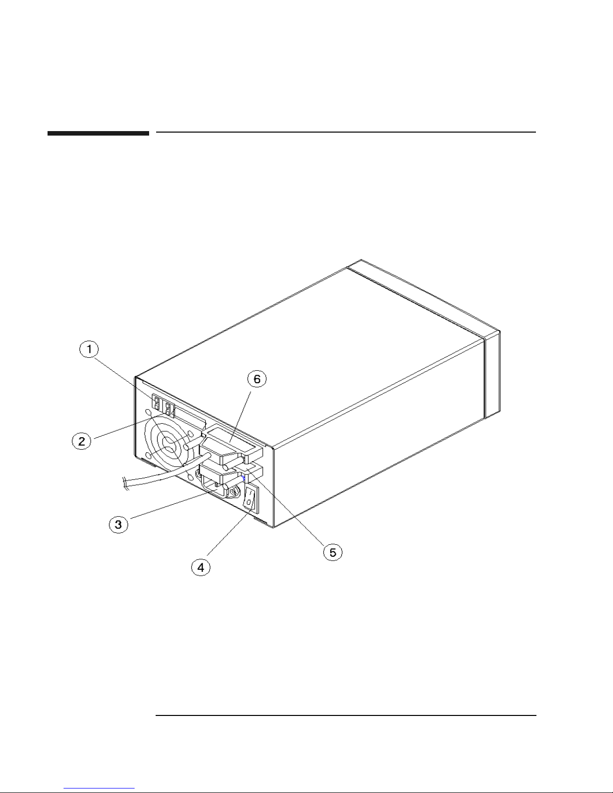
Figure 1-1 Rear Panel Features
1-4 Chapter 1

Setting up the Disk Drive
Rear Panel Features
The following numbers correspond to the numbers in the drawing on the previous
page.
1 SCSI ID switch Used to set the SCSI ID. Refer to “Setting
the SCSI ID” in this section.
2 Operation mode switch Used to choose the operating mode and set
your preference for write verify. Refer to
“Setting the Operation Mode” in this
section.
3 Power connector Receptacle for the power cord.
4 On/Off switch Used to switch power on or off.
Chapter 1: Setting
up the Disk Drive
Setting up the
Disk Drive
5 SCSI connector (with
terminator attached)
6 SCSI connector (with
cable attached)
50-pin high-density SCSI connector
(Micro D-type). Terminator may be
attached to either connector (see “6”).
A terminator must be plugged into either
“5” or “6” when the drive is the last
physical device on a SCSI bus.
50-pin high-density SCSI connector
(Micro D-type). Cable may be attached to
either connector (see “5”).
A terminator must be plugged into either
“5” or “6” when the drive is the last
physical device on a SCSI bus.
Chapter 1 1-5

Setting up the Disk Drive
Connecting the Drive to Your Host Computer
Connecting the Drive to Your Host Computer
The disk drive is a “narrow,” single-ended SCSI-2 device. This means that the drive
connects to a 50-line single-ended-type SCSI bus using 50-pin high-density
connectors.
You can connect the drive to a SCSI bus either as the only device on the bus or as
one of a number of devices on the bus (daisy-chained).
The SCSI ID you choose for this drive identifies the drive on the bus and also sets its
priority for use of the bus. If you would like more information on the operation of
the SCSI bus, refer to Appendix B. Also, refer to your host adapter’s documentation
for guidance on installing this drive on the bus.
The following sections will describe the steps to install this drive onto the bus. You
must do the following:
• Determine and set the drive’s operating mode
• Determine and set the SCSI ID of the drive
• Attach the bus cable and ensure the bus is properly terminated
Setting the Operating Mode and Write Verify
This drive may be operated in two modes:
• as an optical memory device
• as a direct access device
In most cases, you can select the optical memory device mode (which is the default
setting). Choose the “direct access device” mode if your system does not support
optical memory devices or if your system requires a direct access device. Check
your system documentation to determine which mode to select.
In either mode of operation, you have the choice of write verify on or off.
The write verify configuration ensures that data is written reliably to an optical disk.
The drive ships with write verify enabled. Many software applications also default
to this method of writing.
Writing data on a magneto-optical disk requires two passes. The first pass erases the
data in the sector to which data will be written. The second pass writes new data to
that sector.
1-6 Chapter 1

Setting up the Disk Drive
Connecting the Drive to Your Host Computer
When write verify is configured to ON, an additional pass is made over the sector.
This third pass verifies that all data is written correctly to the sector. To add to the
reliability of your data, Hewlett-Packard recommends that you maintain the default
ON setting for write verify. Note that when write verify is ON, write operations take
more time.
To set the device mode and the write verify mode:
1. Determine which operating mode you need (optical memory device or direct
access device) and whether you want write verify ON or OFF.
The following are the selections available on the mode switch:
• 2 - optical memory device with write verify ON (default).
• 0 - optical memory device with write verify OFF.
• 1 - direct access device with write verify OFF.
• 3 - direct access device with write verify ON.
Chapter 1: Setting
up the Disk Drive
Setting up the
Disk Drive
2. Set the operating mode.
a. Locate the operation mode switch on the rear panel of the disk drive (see “2”
on Figure 1-1).
b. Set the operation mode by pushing the button on the top or bottom of the
window (as explained below) with a small screwdriver or the point of a pen:
• the button above the mode window decreases the number by one
• the button below the mode window increases the number by one
NOTE If you change the operation mode with power on, you must power cycle the drive for
the mode to take effect.
Setting the SCSI ID
CAUTION Before disconnecting power to any device on the SCSI bus, make sure the bus is
inactive. Switching off power while the SCSI bus is active can result in data loss
or indeterminate bus states.
1. Turn drive power OFF (“4” on Figure 1-1).
2. Check which SCSI addresses are available. Usually the host bus adapter is set to
7 and the addresses available are in the range 0 to 6.
The default SCSI ID setting of this drive is 4.
Chapter 1 1-7

Setting up the Disk Drive
Connecting the Drive to Your Host Computer
3. Locate the SCSI ID switch on the rear panel of the disk drive (see “1” on Figure
1-1.
4. Set the SCSI ID by pushing the button at the top or bottom of the window (as
explained below) with a small screwdriver or the point of a pen:
• the button above the ID window decreases the number by one
• the button below the ID window increases the number by one
NOTE If you change the SCSI ID with power on, you must power cycle the drive so that
the host recognizes the new ID.
Cabling and Termination
NOTE This drive is a SCSI “fast” device. The maximum allowable length of the SCSI
cable cannot exceed 3 meters (4.9 feet), including the internal cable length of all
peripherals on the bus.
Use 0.5 meter (1.6 ft) as the internal SCSI cable length of this drive.
1. Plug one end of the power cord into the AC line connector on the back of the
optical disk drive and the other end into the power outlet.
2. Press the power switch on the rear of the optical disk drive so that it is in the
“ON” position (press “1”).
3. Switch on the power to the host computer (or if the host computer has been on
during this installation, powercycle the host computer so that it will “see” this
disk drive.
NOTE For some host computers to recognize the optical disk drive, the power to the disk
drive must be switched on before the power to the host computer.
4. Install the drive onto your host system.
Go to the next section for procedures.
1-8 Chapter 1

Setting up the Disk Drive
Connecting the Drive to Your System
Connecting the Drive to Your System
Two methods of connecting the drive to your operating system are described in the
following section:
• if you want to interchange data files betwen Windows and Mac platforms, go to
the next subsection “Connecting the Drive Using the Supplied Windows/Mac
Drivers”
• if data interchange is not necessary, and you are using Windows, HP-UX, IBM
AIX, or Solaris, go to subsection “Connecting the Drive Using Native Operating
System Drivers.”
Connecting the Drive Using the Supplied Windows/Mac
Drivers
Chapter 1: Setting
up the Disk Drive
Setting up the
Disk Drive
The SAI drivers shipped with this drive enable you to format, read, and write 9.1
GB disks with the following operating systems:
• MAC OS 8/9.x HFS and HFS+
• Windows 95/98
• Windows NT 4.0 Service Pack 4 and above
• Windows 2000 Professional (available January, 2001)
Chapter 1 1-9

Setting up the Disk Drive
Connecting the Drive to Your System
Connecting the Drive Using Native Operating System
Drivers
NOTE To use 9.1 Gbyte disks, your operating system must support 4,096 byte-per-sector
media.
Connection to Windows 98
Ensure that power is applied to the drive before applying power to the host
computer. Then do the following steps:
1. Place an optical disk cartridge into the drive.
2. Double click on MY COMPUTER.
3. Right mouse click on the REMOVABLE DISK icon.
4. In the Format dialog box, select FULL under the FORMAT TYPE heading.
5. Under OTHER OPTIONS, enter a disk label name if desired (ex. Backup).
6. Select START. A dialog box displays warning you that a large amount of disk
space will be erased. Click OK.
7. Click CLOSE when the FORMAT RESULTS dialog box displays.
8. Close the dialog box. You are now able to read, write, and erase data on your
disk.
Connection to Windows 2000
Ensure that power is applied to the drive before applying power to the host
computer. Then do the following steps:
1. Place an optical disk cartridge into the drive.
2. Double click on MY COMPUTER.
3. Right mouse click on the REMOVABLE DISK icon.
4. In the Format dialog box, select FULL under the FORMAT TYPE heading.
5. Under OTHER OPTIONS, enter a disk label name if desired (ex. Backup).
6. Select START. A dialog box displays warning you that a large amount of disk
space will be erased. Click OK.
7. Click CLOSE when the FORMAT RESULTS dialog box displays.
1-10 Chapter 1

Setting up the Disk Drive
Connecting the Drive to Your System
8. Close the dialog box. You are now able to read, write, and erase data on your
disk.
Connection to Windows NT 4.0
1. Apply power to the drive.
2. Apply power to your NT computer.
3. After the computer initializes, put a disk into the drive.
4. Select START, then PROGRAMS, then ADMINSTRAIVE TOOLS (Common),
and then DISK ADMINISTRATOR.
When DISK ADMINISTRATOR starts, it may display a message telling you
that this is the first time the program has been run. If you see this message, select
OK.
5. In DISK ADMINISTRATOR, select VIEW, then DISK CONFIGURATION.
Chapter 1: Setting
up the Disk Drive
Setting up the
Disk Drive
You should see this optical drive listed as a disk with “Free Space.”
6. Highlight the Free Space.
7. Select PARTITION, then CREATE.
Create a partition for the full size of the disk. NT does not allow multiple
partitions on removable media. Select and click on OK to accept the entire side
of the disk as a partition.
Select PARTITION, then select COMMIT CHANGES NOW, then YES.
After the partition is set you must format the disk using the following steps.
8. Select TOOLS, then FORMAT.
9. Chose the file system you want to use.
Under FILE SYSTEM, you may choose either FAT or NTFS. The FAT file
system is a 32-bit file system used by Windows for file exchange. The FAT
system supports long file names and will read the entire side (4.5GB) of the disk.
NTFS is NT’s file system. This file system provides enhanced security and the
capability of file compression (readable only by NT hosts).
After selecting the files system, you may also type in a Volume Label for the
disk (example: Sept_Backup)
10. After selecting the file system (and Volume Label, if desired), Select START.
11. Select and click OK when the “Format Complete” message box displays.
Chapter 1 1-11

Setting up the Disk Drive
Connecting the Drive to Your System
IMPORTANT If you have selected NTFS as your file system and choose to write protect a
magneto-optical disk, you will not be able to access the disk.
Connection to HP-UX (10.2, 11.x)
The following instructions apply when using SAM to configure the drive.
1. Log into your host system as superuser.
2. Type sam
3. Highlight and select Disks and File Systems.
4. Highlight and select Disk Devices.
5. Highlight this disk drive (SAM calls it a “SCSI Optical Disk Drive”).
6. Choose Add... and Not using Logic Volumed Manager from the “Actions” menu.
Your HP-UX system configuration now includes this drive.
Creating a File System on the Disk
1. With a disk in the drive, login as superuser.
2. Determine which file system will be used.
The file system types are HFS and VXFS. To specify the file system, enter
option -F <filesystemtype>.
3. Determine the device address of this drive. .
• Run insf -e to build a file of the special device files and their associations.
• Do an ioscan -fn - this gives you a full ioscan that lists the names of the
special device files. The drive “Description” is “C1113M.” You will see a
“target” and a “disk” line.
• Look under the “disk” line. You will see a “raw device file”(rdsk) address.
This is the address you will use as the device address for formatting in the
next step. An example of the addresses you may see on this line is:
/dev/dsk/c0t3d0 /dev/rdsk/c0t3d0
Use the “rdsk” address. In this example, the SCSI portions of the address (#
left to right) are 0=Bus ID, 3=Target ID, and 0=LUN (Logical Unit
Number).
1-12 Chapter 1
 Loading...