


HP SureStore E Tape Library
Model 12/140
User’s Guide
Edition 2
Part Number: C9179-90000
December 2000
Printed in USA
© Copyright 2000 Hewlett-Packard Company
© Copyright 2000 by Crossroads Systems, Inc. All rights reserved.

Notice
This document contains information that is protected by copyright. All
rights are reserved. No part of this document may be photocopied,
reproduced, or translated into another language. The information
contained in this document is subject to change without notice.
Hewlett-Packard makes no warranty of any kind with regard to this
printed material, including, but not limited to, the implied warranties of
merchantability and fitness for a particular purpose. Hewlett-Packard
shall not be liable for errors contained herein or for incidental or
consequential damages in connection with the furnishing, performance,
or use of this material.
See the insert inside the back cover of this manual for important safety
and regulatory information.
Warranty
HP PRODUCT: HP Tape Library Model 12/140
DURATION OF LIMITED WARRANTY: Two Years
1. HP warrants HP hardware, accessories, and supplies against defects
in materials and workmanship for the period specified above. If
Hewlett-Packard receives notice of such defects during the warranty
period, Hewlett-Packard will, at its option, either repair or replace
products which prove to be defective. Replacement products may be
either new or like-new.
2. HP warrants that HP software will not fail to execute its
programming instructions, for the period specified above, due to
defects in material and workmanship when properly installed and
used. If HP receives notice of such defects during the warranty period,
HP will replace software media that does not execute its
programming instructions due to such defects.
ii

3. HP does not warrant that the operation of HP products will be
uninterrupted or error free. If HP is unable, within a reasonable time,
to repair or replace any product to a condition as warranted, customer
will be entitled to a refund of the purchase price upon prompt return
of the product.
4. HP products may contain remanufactured parts equivalent to new in
performance or may have been subject to incidental use.
5. The warranty period begins on the date of delivery or on the date of
installation if installed by HP. If customer schedules or delays HP
installation more than 30 days after delivery, warranty begins on the
31st day from delivery.
6. Warranty does not apply to defects resulting from (a) improper or
inadequate maintenance or calibration, (b) software, interfacing,
parts or supplies not supplied by HP, (c) unauthorized modification or
misuse, (d) operation outside of the published environmental
specifications for the products, or (e) improper site preparation or
maintenance.
7. TO THE EXTENT ALLOWED BY LOCAL LAW, THE ABOVE
WARRANTIES ARE EXCLUSIVE AND NO OTHER WARRANTY
OR CONDITION, WHETHER WRITTEN OR ORAL, IS EXPRESSED
OR IMPLIED AND HP SPECIFICALLY DISCLAIMS ANY IMPLIED
WARRANTIES OR CONDITIONS OF MERCHANTABILITY,
SATISFACTORY QUALITY, AND FITNESS FOR A PARTICULAR
PURPOSE.
8. HP will be liable for damage to tangible property per incident up to
the greater of $300,000 or the actual amount paid for the product that
is the subject of the claim, and for damages for bodily injury or death,
to the extent that all such damages are determined by a court of
competent jurisdiction to have been directly caused by a defective HP
product.
9. TO THE EXTENT ALLOWED BY LOCAL LAW, THE REMEDIES IN
THIS WARRANTY STATEMENT ARE THE CUSTOMER’S SOLE
AND EXCLUSIVE REMEDIES. EXCEPT AS INDICATED ABOVE,
IN NO EVENT WILL HP OR ITS SUPPLIERS BE LIABLE FOR
LOSS OF DATA OR FOR DIRECT, SPECIAL, INCIDENTAL,
CONSEQUENTIAL (INCLUDING LOST PROFIT OR DATA), OR
OTHER DAMAGE, WHETHER BASED IN CONTRACT, TORT, OR
OTHERWISE.
iii

Printing History
New editions of this manual incorporate all material updated since the
previous edition. The manual printing date and part number indicate the
current edition. The printing date changes when a new edition is printed.
(Minor corrections and updates incorporated at reprint do not change
this date.)
Edition 1: June 2000: C9170-90000
Initial printing.
Edition 2: December 2000: C9179-90000
Added the reader comment sheet, and drive and
media information for DLT and Ultrium. Updated
library model number, troubleshooting
procedures, technical specifications, Fibre
Channel configuration, remote management card
features, mailslot options, and front panel
information.
Updates
For the most current version of this manual and other information
regarding your tape library, visit the HP Customer Care website:
www.hp.com/go/support
iv

Typographical Conventions and Terms
Keycap: Menu choices and screens on the library.
[Soft Key]: Soft keys to press on the library.
Computer Output Host and SCSI commands.
This table format indicates the menus you need to enter on the library
front panel:
Main Menu ->
Operations ->
Drive and Tape Operations
WARNING Warnings call attention to a procedure or practice that could
result in personal injury if not correctly performed. Do not
proceed until you fully understand and meet the required
conditions.
CAUTION Cautions call attention to an operating procedure or practice that could
damage the product if not correctly performed. Do not proceed until you
understand and meet these required conditions.
NOTE Notes explain significant concepts or operating instructions.
TIP Tips provide hints or shortcuts for a procedure.
For the purpose of this documentation, we will use the term Model
12/140 to indicate all library models that are five levels and higher.
These models include 4/100, 6/100, 6/120, 6/140, 8/140, 10/140, and
12/140.
v

In This Manual
Chapter 1 Getting Started: Describes library components,
installation and post-installation tasks, and
moving or shipping the library.
Chapter 2 Library Operations: Describes the front panel
menu structure, menu trees, and drive and tape
operations.
Chapter 3 Library Administration: Describes
configuration options, diagnostic tests, and
retrieving information about the library.
Chapter 4 Troubleshooting: Describes how to troubleshoot
library problems, resolve error conditions, and
download firmware.
Appendix A Technical Specifications: Describes the
environmental, library, SCSI cable, and Fibre
Channel cable specifications.
Appendix B Customer Support: Includes support
information for the library.
Appendix C Introduction to Fibre Channel: Describes
Fibre Channel technology, terms, and using Fibre
Channel with the libraries.
Appendix D Drives and Media: Includes information for
DLT and Ultrium drives and media, as well as
compatibility information.
Glossary Glossary of Terms: Includes technical terms
used in this manual.
vi

1. Getting Started
Chapter Overview . . . . . . . . . . . . . . . . . . . . . . . . . . . . . . . . . . . . . . . . . . . . . . . . . . . . . . 1-2
Library Overview . . . . . . . . . . . . . . . . . . . . . . . . . . . . . . . . . . . . . . . . . . . . . . . . . . . . . . . 1-3
Identifying Product Components . . . . . . . . . . . . . . . . . . . . . . . . . . . . . . . . . . . . . . . . . . 1-4
Installing the Library (for Authorized Service Personnel only) . . . . . . . . . . . . . . . . . . . 1-5
Installation Overview . . . . . . . . . . . . . . . . . . . . . . . . . . . . . . . . . . . . . . . . . . . . . . . . . . 1-5
Choosing a Location . . . . . . . . . . . . . . . . . . . . . . . . . . . . . . . . . . . . . . . . . . . . . . . . . . . 1-6
Setting Up the Library . . . . . . . . . . . . . . . . . . . . . . . . . . . . . . . . . . . . . . . . . . . . . . . . . 1-8
Preparing the Host for Installation . . . . . . . . . . . . . . . . . . . . . . . . . . . . . . . . . . . . . . 1-10
Connecting and Powering on the Library . . . . . . . . . . . . . . . . . . . . . . . . . . . . . . . . . 1-11
SCSI Cable Connections . . . . . . . . . . . . . . . . . . . . . . . . . . . . . . . . . . . . . . . . . . . . 1-13
Fibre Channel Cable Connections . . . . . . . . . . . . . . . . . . . . . . . . . . . . . . . . . . . . . 1-16
Configuring the Host System . . . . . . . . . . . . . . . . . . . . . . . . . . . . . . . . . . . . . . . . . . . . 1-22
Windows NT . . . . . . . . . . . . . . . . . . . . . . . . . . . . . . . . . . . . . . . . . . . . . . . . . . . . . . . . 1-22
Sun Solaris . . . . . . . . . . . . . . . . . . . . . . . . . . . . . . . . . . . . . . . . . . . . . . . . . . . . . . . . . 1-22
HP-UX Hosts. . . . . . . . . . . . . . . . . . . . . . . . . . . . . . . . . . . . . . . . . . . . . . . . . . . . . . . . 1-23
Installing the Pass-Through Driver . . . . . . . . . . . . . . . . . . . . . . . . . . . . . . . . . . . . 1-24
Creating a Device File for the Robotics Controller . . . . . . . . . . . . . . . . . . . . . . . . 1-25
Verifying the Installation . . . . . . . . . . . . . . . . . . . . . . . . . . . . . . . . . . . . . . . . . . . . 1-27
MPE/iX Hosts . . . . . . . . . . . . . . . . . . . . . . . . . . . . . . . . . . . . . . . . . . . . . . . . . . . . . . . 1-28
Requirements . . . . . . . . . . . . . . . . . . . . . . . . . . . . . . . . . . . . . . . . . . . . . . . . . . . . . 1-28
Configuring the Host. . . . . . . . . . . . . . . . . . . . . . . . . . . . . . . . . . . . . . . . . . . . . . . . 1-28
Verifying the Connection . . . . . . . . . . . . . . . . . . . . . . . . . . . . . . . . . . . . . . . . . . . . 1-32
Identifying the Post-Installation Tasks . . . . . . . . . . . . . . . . . . . . . . . . . . . . . . . . . . . . 1-33
Moving or Shipping the Library . . . . . . . . . . . . . . . . . . . . . . . . . . . . . . . . . . . . . . . . . . 1-34
Packing the Library for Shipping. . . . . . . . . . . . . . . . . . . . . . . . . . . . . . . . . . . . . . . . 1-39
Contents
2. Library Operations
Chapter Overview . . . . . . . . . . . . . . . . . . . . . . . . . . . . . . . . . . . . . . . . . . . . . . . . . . . . . . 2-2
Front Panel Overview . . . . . . . . . . . . . . . . . . . . . . . . . . . . . . . . . . . . . . . . . . . . . . . . . . . 2-3
Nesting . . . . . . . . . . . . . . . . . . . . . . . . . . . . . . . . . . . . . . . . . . . . . . . . . . . . . . . . . . . . .2-4
Front Panel Display Conventions . . . . . . . . . . . . . . . . . . . . . . . . . . . . . . . . . . . . . . . . 2-5
Front Panel Status Information (Home Screen) . . . . . . . . . . . . . . . . . . . . . . . . . . . . . 2-5
Status Bar . . . . . . . . . . . . . . . . . . . . . . . . . . . . . . . . . . . . . . . . . . . . . . . . . . . . . . . . . . . 2-6
Understanding the Menu Structure . . . . . . . . . . . . . . . . . . . . . . . . . . . . . . . . . . . . . . . . 2-8
Using Tapes . . . . . . . . . . . . . . . . . . . . . . . . . . . . . . . . . . . . . . . . . . . . . . . . . . . . . . . . . . .2-9
Write-Protecting Tape Cartridges . . . . . . . . . . . . . . . . . . . . . . . . . . . . . . . . . . . . . . . . 2-9
Labeling Tape Cartridges. . . . . . . . . . . . . . . . . . . . . . . . . . . . . . . . . . . . . . . . . . . . . . . 2-9
vii

Contents
Maintaining Tape Cartridges. . . . . . . . . . . . . . . . . . . . . . . . . . . . . . . . . . . . . . . . . . . 2-10
Accessing Tapes in the Library . . . . . . . . . . . . . . . . . . . . . . . . . . . . . . . . . . . . . . . . . . . 2-11
Magazine Access . . . . . . . . . . . . . . . . . . . . . . . . . . . . . . . . . . . . . . . . . . . . . . . . . . . . . 2-11
Mailslot Access . . . . . . . . . . . . . . . . . . . . . . . . . . . . . . . . . . . . . . . . . . . . . . . . . . . . . . 2-13
Drive and Tape Operations . . . . . . . . . . . . . . . . . . . . . . . . . . . . . . . . . . . . . . . . . . . . . . 2-14
Loading a Tape Into a Drive. . . . . . . . . . . . . . . . . . . . . . . . . . . . . . . . . . . . . . . . . . . . 2-14
Unloading a Tape from the Drive . . . . . . . . . . . . . . . . . . . . . . . . . . . . . . . . . . . . . . . 2-15
Cleaning a Drive . . . . . . . . . . . . . . . . . . . . . . . . . . . . . . . . . . . . . . . . . . . . . . . . . . . . . 2-15
Moving Tapes Between Slots . . . . . . . . . . . . . . . . . . . . . . . . . . . . . . . . . . . . . . . . . . . 2-16
3. Library Administration
Chapter Overview . . . . . . . . . . . . . . . . . . . . . . . . . . . . . . . . . . . . . . . . . . . . . . . . . . . . . . 3-2
Configuring the Library . . . . . . . . . . . . . . . . . . . . . . . . . . . . . . . . . . . . . . . . . . . . . . . . . 3-3
Enabling and Changing the Password . . . . . . . . . . . . . . . . . . . . . . . . . . . . . . . . . . . . . . 3-5
Configuring the Mailslot . . . . . . . . . . . . . . . . . . . . . . . . . . . . . . . . . . . . . . . . . . . . . . . . . 3-6
Using the Remote Management Card. . . . . . . . . . . . . . . . . . . . . . . . . . . . . . . . . . . . . . . 3-9
Overview . . . . . . . . . . . . . . . . . . . . . . . . . . . . . . . . . . . . . . . . . . . . . . . . . . . . . . . . . . . .3-9
Dynamic Host Configuration Protocol (DHCP) . . . . . . . . . . . . . . . . . . . . . . . . . . . 3-10
BOOTP. . . . . . . . . . . . . . . . . . . . . . . . . . . . . . . . . . . . . . . . . . . . . . . . . . . . . . . . . . . 3-11
Management Programs. . . . . . . . . . . . . . . . . . . . . . . . . . . . . . . . . . . . . . . . . . . . . . 3-11
Configuring the Remote Management Card . . . . . . . . . . . . . . . . . . . . . . . . . . . . . . . 3-12
Retrieving Information about the Remote Management Card . . . . . . . . . . . . . . . . 3-14
Configuring the Library for Fibre Channel . . . . . . . . . . . . . . . . . . . . . . . . . . . . . . . . . 3-15
Configuration . . . . . . . . . . . . . . . . . . . . . . . . . . . . . . . . . . . . . . . . . . . . . . . . . . . . . . . 3-15
Retrieving Information about Fibre Channel . . . . . . . . . . . . . . . . . . . . . . . . . . . . . 3-18
Setting SCSI IDs . . . . . . . . . . . . . . . . . . . . . . . . . . . . . . . . . . . . . . . . . . . . . . . . . . . . . . 3-19
Setting the Date and Time . . . . . . . . . . . . . . . . . . . . . . . . . . . . . . . . . . . . . . . . . . . . . . 3-22
Retrieving Library Information . . . . . . . . . . . . . . . . . . . . . . . . . . . . . . . . . . . . . . . . . . 3-24
Library Information . . . . . . . . . . . . . . . . . . . . . . . . . . . . . . . . . . . . . . . . . . . . . . . . . . 3-24
Drive Information . . . . . . . . . . . . . . . . . . . . . . . . . . . . . . . . . . . . . . . . . . . . . . . . . . . . 3-26
Configuration Information . . . . . . . . . . . . . . . . . . . . . . . . . . . . . . . . . . . . . . . . . . . . . 3-27
Date and Time. . . . . . . . . . . . . . . . . . . . . . . . . . . . . . . . . . . . . . . . . . . . . . . . . . . . . . . 3-27
Firmware Revisions . . . . . . . . . . . . . . . . . . . . . . . . . . . . . . . . . . . . . . . . . . . . . . . . . . 3-28
Power Supplies . . . . . . . . . . . . . . . . . . . . . . . . . . . . . . . . . . . . . . . . . . . . . . . . . . . . . . 3-28
Running Library Diagnostic Tests . . . . . . . . . . . . . . . . . . . . . . . . . . . . . . . . . . . . . . . . 3-29
viii

4. Understanding Errors and Troubleshooting
Chapter Overview . . . . . . . . . . . . . . . . . . . . . . . . . . . . . . . . . . . . . . . . . . . . . . . . . . . . . . 4-2
Troubleshooting Overview. . . . . . . . . . . . . . . . . . . . . . . . . . . . . . . . . . . . . . . . . . . . . . . . 4-3
Understanding Error Types . . . . . . . . . . . . . . . . . . . . . . . . . . . . . . . . . . . . . . . . . . . . . 4-4
Understanding Error States . . . . . . . . . . . . . . . . . . . . . . . . . . . . . . . . . . . . . . . . . . . . . . 4-5
Soft (Recovered) Errors . . . . . . . . . . . . . . . . . . . . . . . . . . . . . . . . . . . . . . . . . . . . . . . . 4-6
Partial Availability State . . . . . . . . . . . . . . . . . . . . . . . . . . . . . . . . . . . . . . . . . . . . . . . 4-8
Hard (Unrecovered) Errors . . . . . . . . . . . . . . . . . . . . . . . . . . . . . . . . . . . . . . . . . . . . 4-13
Clearing the Failed State . . . . . . . . . . . . . . . . . . . . . . . . . . . . . . . . . . . . . . . . . . . . 4-14
Host Software and Media Errors . . . . . . . . . . . . . . . . . . . . . . . . . . . . . . . . . . . . . . . 4-15
Backup Software Errors . . . . . . . . . . . . . . . . . . . . . . . . . . . . . . . . . . . . . . . . . . . . . 4-16
Interpreting Library LEDs . . . . . . . . . . . . . . . . . . . . . . . . . . . . . . . . . . . . . . . . . . . . . . 4-17
Troubleshooting Common Problems . . . . . . . . . . . . . . . . . . . . . . . . . . . . . . . . . . . . . . . 4-28
Diagnostic Support Tools. . . . . . . . . . . . . . . . . . . . . . . . . . . . . . . . . . . . . . . . . . . . . . . . 4-35
HP Library & Tape Tools . . . . . . . . . . . . . . . . . . . . . . . . . . . . . . . . . . . . . . . . . . . . . . 4-35
Support Tools Manager (STM) . . . . . . . . . . . . . . . . . . . . . . . . . . . . . . . . . . . . . . . . . . 4-36
Overview of STM Menu Structure . . . . . . . . . . . . . . . . . . . . . . . . . . . . . . . . . . . . . 4-37
Performing Operations . . . . . . . . . . . . . . . . . . . . . . . . . . . . . . . . . . . . . . . . . . . . . . 4-38
Using the STM Tools. . . . . . . . . . . . . . . . . . . . . . . . . . . . . . . . . . . . . . . . . . . . . . . . 4-38
Reviewing Logs . . . . . . . . . . . . . . . . . . . . . . . . . . . . . . . . . . . . . . . . . . . . . . . . . . . . 4-39
Types of STM Tools for Tape Libraries . . . . . . . . . . . . . . . . . . . . . . . . . . . . . . . . . . . 4-41
Expert Tools. . . . . . . . . . . . . . . . . . . . . . . . . . . . . . . . . . . . . . . . . . . . . . . . . . . . . . . 4-42
Sysdiag . . . . . . . . . . . . . . . . . . . . . . . . . . . . . . . . . . . . . . . . . . . . . . . . . . . . . . . . . . . . 4-48
SCSITAC Sections. . . . . . . . . . . . . . . . . . . . . . . . . . . . . . . . . . . . . . . . . . . . . . . . . . 4-49
SCSIDLT Sections. . . . . . . . . . . . . . . . . . . . . . . . . . . . . . . . . . . . . . . . . . . . . . . . . . 4-49
Removing and Replacing Cards . . . . . . . . . . . . . . . . . . . . . . . . . . . . . . . . . . . . . . . . . . 4-51
Removing a Card. . . . . . . . . . . . . . . . . . . . . . . . . . . . . . . . . . . . . . . . . . . . . . . . . . . . . 4-51
Replacing a Card. . . . . . . . . . . . . . . . . . . . . . . . . . . . . . . . . . . . . . . . . . . . . . . . . . . . . 4-52
Removing and Replacing Drive Modules . . . . . . . . . . . . . . . . . . . . . . . . . . . . . . . . . . . 4-54
Drive Replacement Overview. . . . . . . . . . . . . . . . . . . . . . . . . . . . . . . . . . . . . . . . . . . 4-54
Unloading a Tape from a Drive . . . . . . . . . . . . . . . . . . . . . . . . . . . . . . . . . . . . . . . . . 4-55
Taking a Drive Offline . . . . . . . . . . . . . . . . . . . . . . . . . . . . . . . . . . . . . . . . . . . . . . . . 4-55
Removing a Drive Module . . . . . . . . . . . . . . . . . . . . . . . . . . . . . . . . . . . . . . . . . . . . . 4-56
Installing a Drive Module . . . . . . . . . . . . . . . . . . . . . . . . . . . . . . . . . . . . . . . . . . . . . 4-58
Upgrading Firmware . . . . . . . . . . . . . . . . . . . . . . . . . . . . . . . . . . . . . . . . . . . . . . . . . . . 4-60
Checking the Firmware Revision. . . . . . . . . . . . . . . . . . . . . . . . . . . . . . . . . . . . . . . . 4-61
Using the Remote Management Card (library firmware only) . . . . . . . . . . . . . . . . 4-62
Using a Host Diagnostic Utility (drive and library firmware). . . . . . . . . . . . . . . . . 4-63
Contents
ix

Contents
Using HP Library & Tape Tools (Windows only). . . . . . . . . . . . . . . . . . . . . . . . . . 4-63
Using Support Tools Manager (HP-UX and MPE/iX only) . . . . . . . . . . . . . . . . . . 4-63
Using a Firmware Upgrade Tape (drive firmware only). . . . . . . . . . . . . . . . . . . . . . 4-64
A. Technical Specifications
Appendix Overview . . . . . . . . . . . . . . . . . . . . . . . . . . . . . . . . . . . . . . . . . . . . . . . . . . . . .A-2
Environmental Specifications . . . . . . . . . . . . . . . . . . . . . . . . . . . . . . . . . . . . . . . . . . . . .A-3
Library Specifications . . . . . . . . . . . . . . . . . . . . . . . . . . . . . . . . . . . . . . . . . . . . . . . . . . .A-4
Common Specifications. . . . . . . . . . . . . . . . . . . . . . . . . . . . . . . . . . . . . . . . . . . . . . . . .A-4
Specifications by Model . . . . . . . . . . . . . . . . . . . . . . . . . . . . . . . . . . . . . . . . . . . . . . . .A-5
Cable Specifications . . . . . . . . . . . . . . . . . . . . . . . . . . . . . . . . . . . . . . . . . . . . . . . . . . . . .A-7
SCSI Cables. . . . . . . . . . . . . . . . . . . . . . . . . . . . . . . . . . . . . . . . . . . . . . . . . . . . . . . . . .A-7
Fibre Channel Cables . . . . . . . . . . . . . . . . . . . . . . . . . . . . . . . . . . . . . . . . . . . . . . . . . .A-7
Drive, Media, and Bar Code Specifications . . . . . . . . . . . . . . . . . . . . . . . . . . . . . . . . . .A-8
B. Customer Support
Registering Your Product. . . . . . . . . . . . . . . . . . . . . . . . . . . . . . . . . . . . . . . . . . . . . . . . .B-2
Service Contracts . . . . . . . . . . . . . . . . . . . . . . . . . . . . . . . . . . . . . . . . . . . . . . . . . . . . . . .B-3
Information Needed for Support . . . . . . . . . . . . . . . . . . . . . . . . . . . . . . . . . . . . . . . . . . .B-5
Backup Software Support. . . . . . . . . . . . . . . . . . . . . . . . . . . . . . . . . . . . . . . . . . . . . . .B-5
Supplies and Accessories . . . . . . . . . . . . . . . . . . . . . . . . . . . . . . . . . . . . . . . . . . . . . . . . .B-6
C. Introduction to Fibre Channel
Chapter Overview . . . . . . . . . . . . . . . . . . . . . . . . . . . . . . . . . . . . . . . . . . . . . . . . . . . . . .C-2
Fibre Channel Terminology. . . . . . . . . . . . . . . . . . . . . . . . . . . . . . . . . . . . . . . . . . . . . . .C-3
Fibre Channel with Libraries . . . . . . . . . . . . . . . . . . . . . . . . . . . . . . . . . . . . . . . . . . . . .C-5
Host Prerequisites . . . . . . . . . . . . . . . . . . . . . . . . . . . . . . . . . . . . . . . . . . . . . . . . . . . .C-5
Fibre Channel Technology. . . . . . . . . . . . . . . . . . . . . . . . . . . . . . . . . . . . . . . . . . . . . . . .C-6
Overview of Fibre Technology . . . . . . . . . . . . . . . . . . . . . . . . . . . . . . . . . . . . . . . . . . .C-6
Connection Topologies . . . . . . . . . . . . . . . . . . . . . . . . . . . . . . . . . . . . . . . . . . . . . . . . .C-7
Addressing. . . . . . . . . . . . . . . . . . . . . . . . . . . . . . . . . . . . . . . . . . . . . . . . . . . . . . . . . . .C-8
Device Addresses on a Fibre Channel Loop. . . . . . . . . . . . . . . . . . . . . . . . . . . . . . .C-8
Address Assignments . . . . . . . . . . . . . . . . . . . . . . . . . . . . . . . . . . . . . . . . . . . . . . . .C-8
Address Conflicts. . . . . . . . . . . . . . . . . . . . . . . . . . . . . . . . . . . . . . . . . . . . . . . . . . . .C-8
Ports, Nodes, and World Wide Names . . . . . . . . . . . . . . . . . . . . . . . . . . . . . . . . . . . . .C-9
Fibre Channel Loop State . . . . . . . . . . . . . . . . . . . . . . . . . . . . . . . . . . . . . . . . . . . . . .C-9
x

Hubs and Switches . . . . . . . . . . . . . . . . . . . . . . . . . . . . . . . . . . . . . . . . . . . . . . . . . . . .C-9
Zoning . . . . . . . . . . . . . . . . . . . . . . . . . . . . . . . . . . . . . . . . . . . . . . . . . . . . . . . . . . . . .C-11
Advantages of Fibre Channel. . . . . . . . . . . . . . . . . . . . . . . . . . . . . . . . . . . . . . . . . . .C-12
Distributed Devices . . . . . . . . . . . . . . . . . . . . . . . . . . . . . . . . . . . . . . . . . . . . . . . . .C-12
Cabling Advantages . . . . . . . . . . . . . . . . . . . . . . . . . . . . . . . . . . . . . . . . . . . . . . . .C-12
Addressing . . . . . . . . . . . . . . . . . . . . . . . . . . . . . . . . . . . . . . . . . . . . . . . . . . . . . . . .C-12
Common Problems with Fibre Channel . . . . . . . . . . . . . . . . . . . . . . . . . . . . . . . . . .C-13
Physical Connections . . . . . . . . . . . . . . . . . . . . . . . . . . . . . . . . . . . . . . . . . . . . . . .C-13
Laser Power Control Systems. . . . . . . . . . . . . . . . . . . . . . . . . . . . . . . . . . . . . . . . .C-14
Error Recovery. . . . . . . . . . . . . . . . . . . . . . . . . . . . . . . . . . . . . . . . . . . . . . . . . . . . .C-14
D. Drives and Media
Appendix Overview . . . . . . . . . . . . . . . . . . . . . . . . . . . . . . . . . . . . . . . . . . . . . . . . . . . . D-2
Drive Technologies and Compatibility . . . . . . . . . . . . . . . . . . . . . . . . . . . . . . . . . . . . . D-3
Format Compatibility . . . . . . . . . . . . . . . . . . . . . . . . . . . . . . . . . . . . . . . . . . . . . . . . . D-3
Media Compatibililty . . . . . . . . . . . . . . . . . . . . . . . . . . . . . . . . . . . . . . . . . . . . . . . . . D-3
Quantum DLT Drives & Media . . . . . . . . . . . . . . . . . . . . . . . . . . . . . . . . . . . . . . . . . . . D-5
DLT Drive and Media Specifications . . . . . . . . . . . . . . . . . . . . . . . . . . . . . . . . . . . . . D-5
Using DLT Tape Cartridges . . . . . . . . . . . . . . . . . . . . . . . . . . . . . . . . . . . . . . . . . . . . D-7
Inspecting DLT Cartridges . . . . . . . . . . . . . . . . . . . . . . . . . . . . . . . . . . . . . . . . . . . D-7
Write-Protecting DLT Cartridges. . . . . . . . . . . . . . . . . . . . . . . . . . . . . . . . . . . . . . D-9
Using DLT Cartridge Bar Code Labels . . . . . . . . . . . . . . . . . . . . . . . . . . . . . . . . D-11
DLT Cartridge Bar Code Specifications. . . . . . . . . . . . . . . . . . . . . . . . . . . . . . . . D-12
Using DLT Cleaning Cartridges. . . . . . . . . . . . . . . . . . . . . . . . . . . . . . . . . . . . . . D-12
Loading DLT Cartridges into a Magazine . . . . . . . . . . . . . . . . . . . . . . . . . . . . . . D-13
Troubleshooting DLT Drives . . . . . . . . . . . . . . . . . . . . . . . . . . . . . . . . . . . . . . . . . . D-14
Manually Rewinding a Stuck Tape . . . . . . . . . . . . . . . . . . . . . . . . . . . . . . . . . . . D-14
Removing a Stuck Tape. . . . . . . . . . . . . . . . . . . . . . . . . . . . . . . . . . . . . . . . . . . . . D-16
DLT Cleaning Issues . . . . . . . . . . . . . . . . . . . . . . . . . . . . . . . . . . . . . . . . . . . . . . . D-17
Media Issues . . . . . . . . . . . . . . . . . . . . . . . . . . . . . . . . . . . . . . . . . . . . . . . . . . . . . D-18
HP Ultrium Drives & Media . . . . . . . . . . . . . . . . . . . . . . . . . . . . . . . . . . . . . . . . . . . . D-19
HP Ultrium Drive and Media Specifications. . . . . . . . . . . . . . . . . . . . . . . . . . . . . . D-19
Using HP Ultrium Cartridges . . . . . . . . . . . . . . . . . . . . . . . . . . . . . . . . . . . . . . . . . D-21
Maintaining Ultrium Cartridges . . . . . . . . . . . . . . . . . . . . . . . . . . . . . . . . . . . . . D-21
Write-Protecting Ultrium Cartridges. . . . . . . . . . . . . . . . . . . . . . . . . . . . . . . . . . D-22
Using Ultrium Cartridge Bar Code Labels . . . . . . . . . . . . . . . . . . . . . . . . . . . . . D-23
Using Ultrium Cleaning Cartridges. . . . . . . . . . . . . . . . . . . . . . . . . . . . . . . . . . . D-25
Loading Ultrium Cartridges into a Magazine . . . . . . . . . . . . . . . . . . . . . . . . . . . D-26
Contents
xi

Contents
Troubleshooting HP Ultrium Drives . . . . . . . . . . . . . . . . . . . . . . . . . . . . . . . . . . . . D-27
Rewinding/Removing a Stuck Tape . . . . . . . . . . . . . . . . . . . . . . . . . . . . . . . . . . . D-27
Ultrium Cleaning Issues. . . . . . . . . . . . . . . . . . . . . . . . . . . . . . . . . . . . . . . . . . . . D-28
LTO-Cartridge Memory (LTO-CM) Issues . . . . . . . . . . . . . . . . . . . . . . . . . . . . . . D-29
xii

Tables
Table 1-1. Supplied Components . . . . . . . . . . . . . . . . . . . . . . . . . . . . . . . . . . . . . . . . . 1-4
Table 1-2. Location Criteria. . . . . . . . . . . . . . . . . . . . . . . . . . . . . . . . . . . . . . . . . . . . . 1-6
Table 1-3. Library Back Panel . . . . . . . . . . . . . . . . . . . . . . . . . . . . . . . . . . . . . . . . . . 1-12
Table 1-4. SCSI Cable Connections (Model 12/140) . . . . . . . . . . . . . . . . . . . . . . . . . 1-15
Table 1-5. Fibre Channel Connections (Model 12/140). . . . . . . . . . . . . . . . . . . . . . . 1-20
Table 1-6. Drivers Needed . . . . . . . . . . . . . . . . . . . . . . . . . . . . . . . . . . . . . . . . . . . . . 1-23
Table 2-1. Drive Icons. . . . . . . . . . . . . . . . . . . . . . . . . . . . . . . . . . . . . . . . . . . . . . . . . . 2-7
Table 2-2. Library Icons . . . . . . . . . . . . . . . . . . . . . . . . . . . . . . . . . . . . . . . . . . . . . . . . 2-7
Table 3-1. Configuration Options . . . . . . . . . . . . . . . . . . . . . . . . . . . . . . . . . . . . . . . . 3-3
Table 3-2. Default Configuration Settings . . . . . . . . . . . . . . . . . . . . . . . . . . . . . . . . . 3-4
Table 3-3. Mailslot Configuration . . . . . . . . . . . . . . . . . . . . . . . . . . . . . . . . . . . . . . . . 3-7
Table 3-4. Supported Configurations . . . . . . . . . . . . . . . . . . . . . . . . . . . . . . . . . . . . 3-11
Table 3-5. Default SCSI IDs . . . . . . . . . . . . . . . . . . . . . . . . . . . . . . . . . . . . . . . . . . . 3-20
Table 3-6. World Time Zones . . . . . . . . . . . . . . . . . . . . . . . . . . . . . . . . . . . . . . . . . . . 3-23
Table 3-7. Library Information . . . . . . . . . . . . . . . . . . . . . . . . . . . . . . . . . . . . . . . . . 3-25
Table 3-8. Front Panel Diagnostic Tests . . . . . . . . . . . . . . . . . . . . . . . . . . . . . . . . . . 3-29
Table 4-1. Partial Availability Conditions. . . . . . . . . . . . . . . . . . . . . . . . . . . . . . . . . . 4-9
Table 4-2. Library Back View . . . . . . . . . . . . . . . . . . . . . . . . . . . . . . . . . . . . . . . . . . 4-18
Table 4-3. Slave Controller LED . . . . . . . . . . . . . . . . . . . . . . . . . . . . . . . . . . . . . . . . 4-19
Table 4-4. Library Expansion Card LED . . . . . . . . . . . . . . . . . . . . . . . . . . . . . . . . . 4-20
Table 4-5. Remote Management Card LEDs . . . . . . . . . . . . . . . . . . . . . . . . . . . . . . 4-21
Table 4-6. HVDS Library Controller Card LEDs . . . . . . . . . . . . . . . . . . . . . . . . . . . 4-22
Table 4-7. LVDS Library Controller Card LEDs . . . . . . . . . . . . . . . . . . . . . . . . . . . 4-23
Table 4-8. Standard Performance Fibre Channel Interface LEDs . . . . . . . . . . . . . 4-24
Table 4-9. High Performance Fibre Channel Interface LEDs . . . . . . . . . . . . . . . . . 4-25
Table 4-10. Drive Module LEDs . . . . . . . . . . . . . . . . . . . . . . . . . . . . . . . . . . . . . . . . 4-26
Table 4-11. Redundant Power Supply LEDs. . . . . . . . . . . . . . . . . . . . . . . . . . . . . . . 4-27
Table 4-12. Troubleshooting Table . . . . . . . . . . . . . . . . . . . . . . . . . . . . . . . . . . . . . . 4-28
Table 4-13. Supported Tool Characteristics . . . . . . . . . . . . . . . . . . . . . . . . . . . . . . . 4-41
Table 4-14. Drive Expert Tool Command . . . . . . . . . . . . . . . . . . . . . . . . . . . . . . . . . 4-42
Table 4-15. Robotic Controller Expert Tool Command. . . . . . . . . . . . . . . . . . . . . . . 4-44
Table 4-16. SCSITAC Interactive Commands . . . . . . . . . . . . . . . . . . . . . . . . . . . . . 4-49
Table 4-17. SCSIDLT Interactive Commands. . . . . . . . . . . . . . . . . . . . . . . . . . . . . . 4-50
Table 4-18. Library Card Positions . . . . . . . . . . . . . . . . . . . . . . . . . . . . . . . . . . . . . . 4-53
xiii

Tables
Table A-1. Environmental Specifications . . . . . . . . . . . . . . . . . . . . . . . . . . . . . . . . . .A-3
Table A-2. Common Library Specifications . . . . . . . . . . . . . . . . . . . . . . . . . . . . . . . .A-4
Table A-3. Unique Library Specifications . . . . . . . . . . . . . . . . . . . . . . . . . . . . . . . . . .A-5
Table A-4. SCSI Cable Specifications . . . . . . . . . . . . . . . . . . . . . . . . . . . . . . . . . . . . .A-7
Table A-5. Fibre Channel Cable Specifications . . . . . . . . . . . . . . . . . . . . . . . . . . . . .A-7
Table B-1. Hardware Service Contracts . . . . . . . . . . . . . . . . . . . . . . . . . . . . . . . . . . .B-3
Table B-2. Response Level Upgrades . . . . . . . . . . . . . . . . . . . . . . . . . . . . . . . . . . . . .B-4
Table C-1. Fibre Channel Topologies. . . . . . . . . . . . . . . . . . . . . . . . . . . . . . . . . . . . . .C-7
Table D-1. Drive Format Compatibility . . . . . . . . . . . . . . . . . . . . . . . . . . . . . . . . . . .D-3
Table D-2. Data Cartridge Compatibility (Unformatted) . . . . . . . . . . . . . . . . . . . . .D-3
Table D-3. Cleaning Cartridges . . . . . . . . . . . . . . . . . . . . . . . . . . . . . . . . . . . . . . . . . .D-4
Table D-4. DLT Drive Specifications . . . . . . . . . . . . . . . . . . . . . . . . . . . . . . . . . . . . . .D-5
Table D-5. DLT Media Specifications . . . . . . . . . . . . . . . . . . . . . . . . . . . . . . . . . . . . .D-6
Table D-6. DLT Cleaning Issues . . . . . . . . . . . . . . . . . . . . . . . . . . . . . . . . . . . . . . . .D-17
Table D-7. Media Issues. . . . . . . . . . . . . . . . . . . . . . . . . . . . . . . . . . . . . . . . . . . . . . .D-18
Table D-8. Ultrium Drive Specifications . . . . . . . . . . . . . . . . . . . . . . . . . . . . . . . . . .D-19
Table D-9. Ultrium Media Specifications . . . . . . . . . . . . . . . . . . . . . . . . . . . . . . . . .D-20
Table D-10. Ultrium Cartridge Bar Code Specifications . . . . . . . . . . . . . . . . . . . . .D-24
Table D-11. Ultrium Cleaning Issues . . . . . . . . . . . . . . . . . . . . . . . . . . . . . . . . . . . .D-28
Table D-12. LTO-CM Issues. . . . . . . . . . . . . . . . . . . . . . . . . . . . . . . . . . . . . . . . . . . .D-29
xiv

Figures
Figure 1-1. Front and Rear Views of the Library . . . . . . . . . . . . . . . . . . . . . . . . . . . . 1-3
Figure 1-2. Library Cabinet Hole Pattern . . . . . . . . . . . . . . . . . . . . . . . . . . . . . . . . . 1-8
Figure 1-3. Attaching the Pallet Shipping Brackets for Mounting . . . . . . . . . . . . . . 1-9
Figure 1-4. Fibre Channel Cabling Alternatives . . . . . . . . . . . . . . . . . . . . . . . . . . . 1-16
Figure 1-5. Fibre Channel GBIC Connections . . . . . . . . . . . . . . . . . . . . . . . . . . . . . 1-18
Figure 1-6. Fibre Channel Connections (Model 12/140). . . . . . . . . . . . . . . . . . . . . . 1-21
Figure 1-7. Rolling the Library onto the Shipping Pallet . . . . . . . . . . . . . . . . . . . . 1-39
Figure 1-8. Attaching the Pallet Shipping Brackets . . . . . . . . . . . . . . . . . . . . . . . . 1-40
Figure 1-9. Adding Packaging Materials to the Library . . . . . . . . . . . . . . . . . . . . . 1-41
Figure 1-10. Attaching the Clips and Banding Straps. . . . . . . . . . . . . . . . . . . . . . . 1-42
Figure 2-1. Library Front Panel . . . . . . . . . . . . . . . . . . . . . . . . . . . . . . . . . . . . . . . . . 2-3
Figure 2-2. Nesting. . . . . . . . . . . . . . . . . . . . . . . . . . . . . . . . . . . . . . . . . . . . . . . . . . . . 2-4
Figure 2-3. Model 12/140 Home Screen . . . . . . . . . . . . . . . . . . . . . . . . . . . . . . . . . . . 2-5
Figure 2-4. Status Bar from Main Menu Screen . . . . . . . . . . . . . . . . . . . . . . . . . . . . 2-6
Figure 2-5. Front Panel Menu Structure . . . . . . . . . . . . . . . . . . . . . . . . . . . . . . . . . . 2-8
Figure 2-6. Removing/Replacing a Magazine . . . . . . . . . . . . . . . . . . . . . . . . . . . . . . 2-12
Figure 3-1. Model 12/140 Mailslot Door . . . . . . . . . . . . . . . . . . . . . . . . . . . . . . . . . . . 3-6
Figure 3-2. RMC Web Interface. . . . . . . . . . . . . . . . . . . . . . . . . . . . . . . . . . . . . . . . . . 3-9
Figure 4-1. Using the Soft Error Log . . . . . . . . . . . . . . . . . . . . . . . . . . . . . . . . . . . . . 4-7
Figure 4-2. Ribbon Cable and Connector . . . . . . . . . . . . . . . . . . . . . . . . . . . . . . . . . 4-56
Figure 4-3. Removing a Drive . . . . . . . . . . . . . . . . . . . . . . . . . . . . . . . . . . . . . . . . . . 4-57
Figure 4-4. Installing a Drive Module. . . . . . . . . . . . . . . . . . . . . . . . . . . . . . . . . . . . 4-58
Figure D-1. Leader in Correct Position, Hub, and Door Lock Tab. . . . . . . . . . . . . . .D-8
Figure D-2. DLT Write-Protect Button Settings . . . . . . . . . . . . . . . . . . . . . . . . . . .D-10
Figure D-3. Proper DLT Label Position . . . . . . . . . . . . . . . . . . . . . . . . . . . . . . . . . .D-11
Figure D-4. Loading DLT Tapes into a Magazine. . . . . . . . . . . . . . . . . . . . . . . . . . .D-13
Figure D-5. Rewinding a Tape in the DLT Drive Module . . . . . . . . . . . . . . . . . . . .D-15
Figure D-6. Spring-Loaded Latch and Thumb-Wheel . . . . . . . . . . . . . . . . . . . . . . .D-16
Figure D-7. Ultrium Format Trademark . . . . . . . . . . . . . . . . . . . . . . . . . . . . . . . . .D-20
Figure D-8. Ultrium Write-Protect Button Settings . . . . . . . . . . . . . . . . . . . . . . . .D-22
Figure D-9. Proper Ultrium Label Position . . . . . . . . . . . . . . . . . . . . . . . . . . . . . . .D-23
Figure D-10. Loading Tapes into a Magazine. . . . . . . . . . . . . . . . . . . . . . . . . . . . . .D-26
xv

Figures
xvi

Getting Started
1 Getting Started
Chapter 1 1-1

Getting Started
Chapter Overview
Chapter Overview
This chapter describes the following:
• Library Overview
• Identifying Product Components
• Installing the Library (for Authorized Service Personnel only)
• Configuring the Host System
• Identifying the Post-Installation Tasks
• Moving or Shipping the Library
Chapter 11-2

Library Overview
Figure 1-1 identifies the locations and names of the library’s major
components.
Figure 1-1 Front and Rear Views of the Library
Getting Started
Getting Started
Library Overview
1 Cabinet side panels 5 Power (standby)
switch
2 Mailslot 6 Anti-tip rails 9 Power cord
3 Front panel display 7 Leveler feet 10 Product information labels
4 Service access panel
Chapter 1 1-3
8 Power distribution unit

Getting Started
Identifying Product Components
Identifying Product Components
The components listed in Table 1-1 may be supplied with the library,
depending on the library configuration.
NOTE Visit www.hp.com/support/tapelibrary for additional information,
including access to the HP Library & Tape Tools diagnostic utility and
compatibility information for backup software.
Table 1-1 Supplied Components
Component Description
SCSI terminator 68-pin SCSI terminator (HVDS or LVDS) to terminate the SCSI
chain.
SCSI jumper cable 68-pin cable that connects the library controller or Fibre
Channel interface to a drive.
Fibre Channel cable Optical short-wave cable (16 meters) that connects the Fibre
Channel interface to the host, hub, or switch (for Fibre Channel
configurations).
Fibre Channel GBIC Connects the Fibre Channel cable to the host, hub, or switch.
(For Fibre Channel configurations with standard performance
Fibre Channel interfaces only. See page 4-24 and page 4-25 for
descriptions.)
Data cartridges Data cartridges included for data backup.
Cleaning cartridge Cleaning cartridge used when cleaning a drive.
Label kit Bar code labels for data and cleaning cartridges, and reordering
information.
User’s guide Printed English user’s guide describing installation,
configuration, operations, and troubleshooting.
Miscellaneous
information
May include data sheets, upgrade information, product
information, and additional promotions.
Chapter 11-4

Getting Started
Installing the Library (for Authorized Service Personnel only)
Installing the Library (for Authorized Service
Personnel only)
NOTE The power cord is factory installed. Libraries that are shipped to
Argentina, Brazil, Chile, China, Hong Kong, Israel, Laos, Paraguay,
Peru, Philippines, Singapore, and Thailand will have a stripped power
cord. The appropriate connector must be installed by an electrician.
Installation Overview
Below are the steps involved in setting up the library. These steps are
explained in more detail on the following pages.
• Choose a location.
Getting Started
• Unpackage the library.
• Install the host bus adapter(s) and drivers.
• Connect the host SCSI cables.
• Connect the Fibre Channel cables (if the library is configured for
Fibre Channel).
• Connect the remote management card to the LAN.
• Connect the power cable.
• Power on the library, peripherals, and the host.
• Configure the host system.
Chapter 1 1-5

Getting Started
Installing the Library (for Authorized Service Personnel only)
Choosing a Location
Choose a location that meets the criteria listed in Table 1-2. For
additional specifications, refer to Appendix A or the product information
labels located on the back of the library.
NOTE Locate the AC outlet near the library. The AC power cord is this product’s
main AC disconnect device and must be easily accessible at all times.
Table 1-2 Location Criteria
Room
temperature
Power source • AC power voltage: 100-127 V or 200-240 V
Library power
consumption
LAN
connection
10-35º C (50-95º F)
Autoselecting
• Line frequency: 50-60 Hz
• A dedicated circuit is required
NOTE: The power cord supplied with the library is
4.5 meters (14.76 feet) in length.
Model 4/100 Typical: 425W, Max: 450W
Model 6/100 Typical: 565W, Max: 600W
Model 6/120 Typical: 590W, Max: 625W
Model 6/140 Typical: 615W, Max: 650W
Model 8/140 Typical: 755W, Max: 800W
Model 10/140 Typical: 895W, Max 950W
Model 12/140 Typical: 1035W, Max 1100W
Locate the library near a LAN connection for
connecting the remote management card.
Chapter 11-6

Table 1-2 Location Criteria
Air quality Minimal sources of particulate contamination. Avoid
Humidity 20-80% RH
Clearance Back Minimum of 55.88 cm (22 inches)
Floor rating A fully loaded library can weigh up to 385.48 kg (850
Getting Started
Getting Started
Installing the Library (for Authorized Service Personnel only)
areas near frequently used doors and walkways,
stacks of supplies that collect dust, and smoke-filled
rooms.
CAUTION: Excessive dust and debris can damage
tapes and tape drives.
Front Minimum of 190.5 cm (75 inches)
Sides Minimum of 5.08 cm (2 inches)
lbs). Each caster supports up to 96.37 kg (212.5 lbs).
To support the weight exerted on the floor by the
casters, the floor rating must meet or exceed 1,694
kg per square meter (347 lbs per square foot).
Tip rating Do not tip the library more than 10°. Ensure that the
location for the library has a level surface.
Chapter 1 1-7

Getting Started
Installing the Library (for Authorized Service Personnel only)
Setting Up the Library
1. Carefully move the library to the installation location (see “Choosing
a Location” on page 1-6).
2. Lower the library’s leveler feet using a 1/2-inch open-end wrench.
3. Secure the library to the floor (optional). Figure 1-2 illustrates the
library cabinet hole pattern for attaching floor mounting brackets.
The pattern is repeated on the front and rear of the cabinet base. All
holes are threaded 1/4 - 20.
Figure 1-2 Library Cabinet Hole Pattern
Chapter 11-8
Installing the Library (for Authorized Service Personnel only)
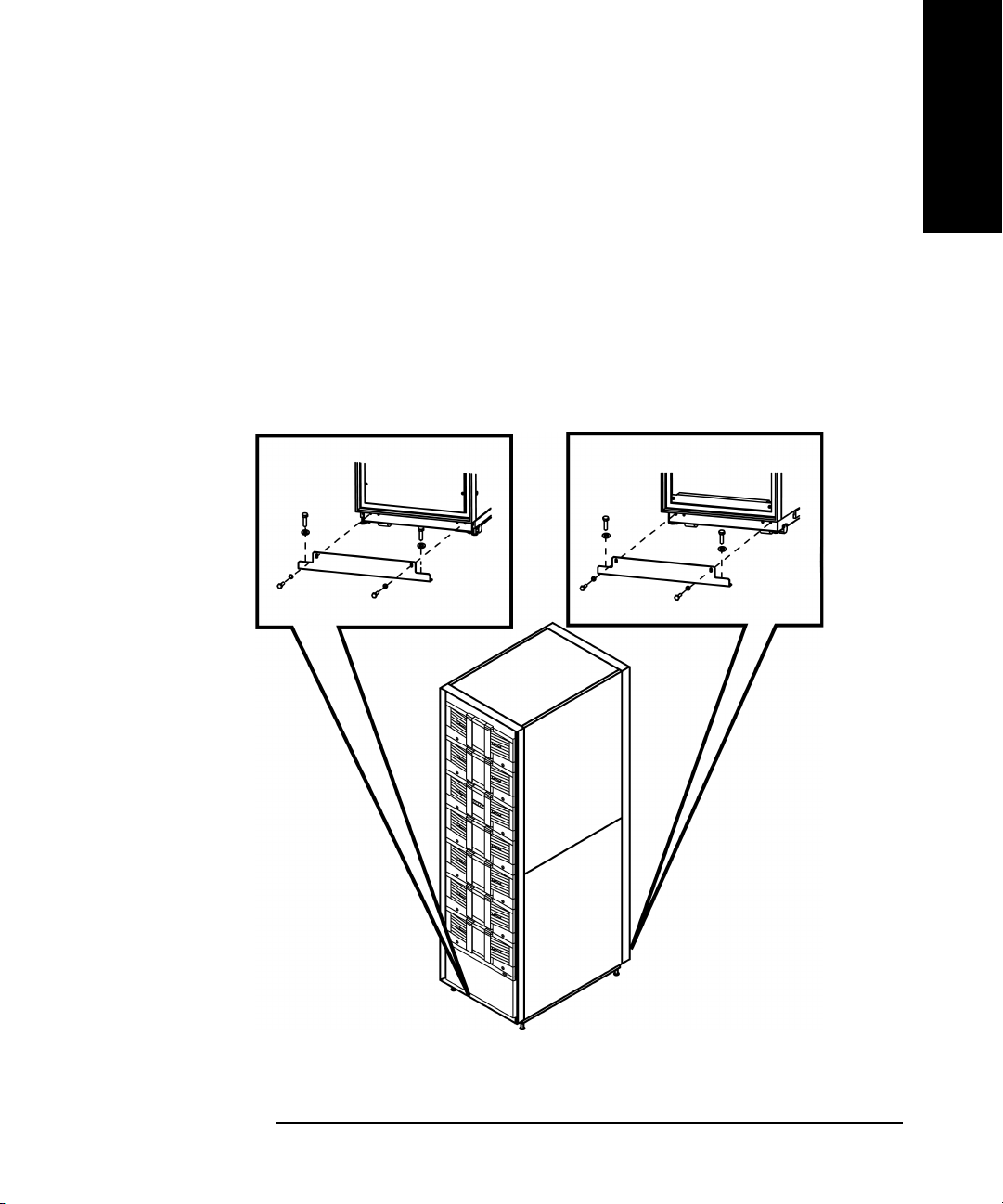
4. You can use the pallet shipping brackets that previously secured the
library to the pallet to mount the library to the floor (see Figure 1-3).
These brackets may have been stored with the library packaging
materials.
• Use a 7/16 socket wrench to attach the two bolts that secure each
bracket to the library.
• Use a 9/16 socket wrench to attach the two bolts that secure each
bracket to the floor.
Figure 1-3 Attaching the Pallet Shipping Brackets for Mounting
Getting Started
Getting Started
Chapter 1 1-9

Getting Started
Installing the Library (for Authorized Service Personnel only)
Preparing the Host for Installation
NOTE Ensure that you have a host bus adapter card that is compatible with the
library.
Install the SCSI host bus adapter card(s) and compatible driver(s). Refer
to the host computer user manual and host bus adapter card
instructions, and follow these general steps:
1. When the host is powered on, install software and/or driver(s) into the
host that are compatible with the library.
2. If the host computer is connected to a network, check with the system
administrator before turning off power.
3. Properly power off all peripheral devices connected to the host
computer.
4. Power off the host.
• User proper procedures to prevent electrostatic discharge (ESD).
U s e w r i s t - g r o u n d i n g s t r a p s a n d a n t i - s t a t i c m a t s w h e n r e m o v i n g
internal components.
• Make sure that the host computer has an appropriate number of
card expansion slots available for your library model.
• Ensure the host bus adapter card is supported by your backup
software application.
• For optimum performance, there should be a maximum of one tape
drive per bus. HP supports up to two drives per SCSI host bus
adapter but recommends only one drive per bus. If compression is
used when attaching two drives per bus, keep in mind the
combined transfer rate of the drives must not exceed the
throughput of the host bus adapter used.
• Refer to Appendix A and the ANSI SCSI cable specification for
more information on SCSI cable length requirements.
• Check for available SCSI IDs if you are installing the library onto
the same SCSI bus as other devices. You might need to change the
SCSI ID from the library front panel if you think there will be an
ID conflict with other devices.
Chapter 11-10

Getting Started
Installing the Library (for Authorized Service Personnel only)
Connecting and Powering on the Library
This section includes information and illustrations for the following:
• Library back panel
• SCSI cable connections
• Fibre Channel cable connections
The figures in this section depict library Model 12/140. The number of
drives and cards will vary, depending on the model.
NOTE The power cord is factory installed. Libraries that are shipped to
Argentina, Brazil, Chile, China, Hong Kong, Israel, Laos, Paraguay,
Peru, Philippines, Singapore, and Thailand will have a stripped power
cord. The appropriate connector must be installed by an electrician.
Getting Started
Chapter 1 1-11

Getting Started
Installing the Library (for Authorized Service Personnel only)
Table 1-3 Library Back Panel
1 Vacant slot
2 Remote management card
3 Library controller card
4 Fibre Channel interface
(optional)
5 Slave controller card
6 Library expansion card
7Empty drive bay
8 Power supply (standard or
redundant)
9 Product information labels
Chapter 11-12

Getting Started
Installing the Library (for Authorized Service Personnel only)
SCSI Cable Connections
NOTE Refer to “Fibre Channel Cable Connections” on page 1-16 if the library is
configured with Fibre Channel.
This section illustrates a standard SCSI configuration that produces a
high level of data storage performance (one SCSI host bus adapter for
each drive in the library, with the library controller daisy-chained to the
first drive). HP supports up to two drives per SCSI host bus adapter, but
recommends only one drive per bus. If compression is used when
attaching two drives per bus, keep in mind the combined transfer rate of
the drives must not exceed the throughput of the host bus adapter used
or performance will be degraded.
Connect the library as follows (refer to Table 1-4 on page 1-15):
1. Properly power off all peripheral devices connected to the host
computer.
Getting Started
2. Power off the host. If the host is connected to a network, check with
the system administrator before turning off power.
3. Connect a 68-pin jumper cable from the top connector of the library
controller to the left drive module on level 1 (drive module 1).
CAUTION Use SCSI cables and HVDS differential terminators for high-voltage
SCSI interfaces. User SCSI cables and LVDS differential terminators for
low-voltage SCSI interfaces. The label on the library controller indicates
high- or low-voltage.
4. Connect the appropriate 68-pin SCSI terminator to the bottom
connector on the library’s controller card.
5. Connect a 68-pin SCSI cable from a host SCSI card to each drive
module. Add the appropriate terminators to the remaining SCSI
connectors.
6. Connect the remote management card (see “Using the Remote
Management Card” on page 3-9).
Chapter 1 1-13

Getting Started
Installing the Library (for Authorized Service Personnel only)
WARNING
Note the high leakage label on the back of the library before connecting power to
the library.
NOTE The AC power cord is the library’s main AC disconnect device and must
be easily accessible at all times.
7. Connect the power cord from the power distribution unit to a
dedicated, grounded power receptacle.
8. Power on the library. The power (standby) switch is recessed and on
the lowest level on the front of the library.
After the power-up test is complete (after several minutes), you will
see the Home Screen on the library’s front panel. The Home Screen
displays the status of the drives and library. See “Front Panel Status
Information (Home Screen)” on page 2-5.
9. Power on other peripherals, and then the host.
Chapter 11-14

Installing the Library (for Authorized Service Personnel only)
Table 1-4 SCSI Cable Connections (Model 12/140)
1 Host (user configured)
2 Remote management card
LAN connection
3 Appropriate 68-pin SCSI
terminator
4 SCSI cable from the library
controller card to drive 1
5 Host SCSI cable to drive 1
6 Host SCSI cable to drive 2
Getting Started
Getting Started
7 Host SCSI cable to drive 4
8 Host SCSI cable to drive 3
9 Host SCSI cable to drive 6
10 Host SCSI cable to drive 5
11 Host SCSI cable to drive 8
12 Host SCSI cable to drive 7
13 Host SCSI cable to drive 10
14 Host SCSI cable to drive 9
15 Host SCSI cable to drive 12
16 Host SCSI cable to drive 11
Chapter 1 1-15

Getting Started
Installing the Library (for Authorized Service Personnel only)
Fibre Channel Cable Connections
NOTE If you are not familiar with Fibre Channel technology, refer to Appendix
C for an overview.
There are several Fibre Channel cabling options. Figure 1-4 provides an
overview.
NOTE When using hubs or switches, consult the user documentation for those
products. For detailed information on HP supported topologies, refer to
the SAN Solution Installation Guide available from www.hp.com/go/
support.
Figure 1-4 Fibre Channel Cabling Alternatives
Cabling Alternative #1:
Connecting the library
directly to a host
Host Library
Cabling Alternative #2:
Connecting the library to
the host through a hub or
switch (more detailed
instructions are on the
following pages)
Cabling Alternative #3:
Connecting the library
multiple hosts through a
hub or switch
Host Library
Host
Host
Hub/Switch
Hub/Switch
Library
Chapter 11-16

Getting Started
Installing the Library (for Authorized Service Personnel only)
The following steps illustrate a Fibre Channel connection between the
host, hub or switch, and library. Refer to Table 1-5 on page 1-20 and
Figure 1-6 on page 1-21, and connect the library as follows:
1. Ensure that the library and host are inactive, and the library is
disconnected from the host.
2. Ensure that the required host software has been installed.
3. Power off the host, hub, or switch. If the host is connected to a
network, check with the system administrator before turning off
power.
4. Install a host bus adapter into the host computer. Use proper
procedures to prevent electrostatic discharge (ESD). Use wristgrounding straps and anti-static mats when removing internal
components.
5. Connect the hardware.
Getting Started
a. On each level of the library that has a drive module, connect a
SCSI jumper cable from bus 1 on each Fibre Channel interface to
the left connector on the left drive module.
b. Connect a SCSI jumper cable from bus 2 on each Fibre Channel
interface to the left connector on the right drive module.
c. Connect a SCSI jumper cable from the top connector on the library
controller card to the right connector on the left drive module on
level 1 (drive module 1) to daisy-chain the library controller to the
drive.
d. Terminate the bottom connector on the library controller card.
e. Connect the appropriate SCSI terminator to the remaining
connectors on the drive modules. Ensure that the interface type
matches your library.
f. Connect the Fibre Channel cable(s) to the host, hub, or switch.
— For the standard performance Fibre Channel interface, a GBIC
is required. (See Figure 1-5 on page 1-18.)
Chapter 1 1-17

Getting Started
Installing the Library (for Authorized Service Personnel only)
Figure 1-5 Fibre Channel GBIC Connections
NOTE Your Fibre Channel interface type (standard or high performance) is
dependent on the drive technology in your library. To identify your Fibre
Channel interface, see page 4-24 and page 4-25 for descriptions.
CAUTION The Fibre Channel printed circuit boards contain a laser system (GBIC or
GLM module) that is classified as a “Class-I Laser Product” under a U.S.
Department of Health and Human Services (DHHS) Radiation
Performance standard according to the Radiation Control for Health and
Safety Act of 1968 and EN60825-1(+A11) safety of laser products. The
compliance statement is located on the module.
6. Power on the hub or switch (if present).
Chapter 11-18

Getting Started
Installing the Library (for Authorized Service Personnel only)
WARNING
Note the high leakage label on the back of the library before connecting power to
the library.
Getting Started
NOTE The AC power cord is the library’s main AC disconnect device and must
be easily accessible at all times.
7. Connect the power cord from the power distribution unit to a
grounded power receptacle, and power on the library. The power
(standby) switch is recessed and on the lowest level on the front of the
library.
After the power-up test is complete (after several minutes), you will
see the Home Screen on the library’s front panel. The Home Screen
displays the status of the drives and library. See “Front Panel Status
Information (Home Screen)” on page 2-5.
8. From the front panel, configure the library for Fibre Channel. See
“Configuring the Library for Fibre Channel” on page 3-15 for more
information.
9. Connect the remote management card (see “Using the Remote
Management Card” on page 3-9).
10.Power on the host.
Chapter 1 1-19

Getting Started
Installing the Library (for Authorized Service Personnel only)
Table 1-5 Fibre Channel Connections (Model 12/140)
1 Host (user configured)
2Hub or switch
3 Remote management card LAN connection
4 Fibre Channel cable
5 SCSI cable from library controller to drive 1
6 Appropriate SCSI terminator
7 SCSI cable from bus 1 on the Fibre Channel interface to drive 1
8 SCSI cable from bus 2 on the Fibre Channel interface to drive 2
9 SCSI cable from bus 2 on the Fibre Channel interface to drive 4
10 SCSI cable from bus 1 on the Fibre Channel interface to drive 3
11 SCSI cable from bus 2 on the Fibre Channel interface to drive 6
12 SCSI cable from bus 1 on the Fibre Channel interface to drive 5
13 SCSI cable from bus 2 on the Fibre Channel interface to drive 8
14 SCSI cable from bus 1 on the Fibre Channel interface to drive 7
15 SCSI cable from bus 2 on the Fibre Channel interface to drive 10
16 SCSI cable from bus 1 on the Fibre Channel interface to drive 9
17 SCSI cable from bus 2 on the Fibre Channel interface to drive 12
18 SCSI cable from bus 1 on the Fibre Channel interface to drive 11
Chapter 11-20

Installing the Library (for Authorized Service Personnel only)
Figure 1-6 Fibre Channel Connections (Model 12/140)
Getting Started
Getting Started
Chapter 1 1-21

Getting Started
Configuring the Host System
Configuring the Host System
Once the library is connected to a host, the Windows NT, Sun
Solaris, HP-UX, and MPE/iX operating systems must be configured
to recognize it. The procedures are different, depending on the host
system.
Windows NT
For Windows NT operating systems, perform the following operating
system configurations:
• Install the appropriate host bus adapter(s)
• Install the corresponding drivers for the interface card(s)
• Install the backup software
To verify the installation, look for the library and drive after powering up
the host.
• Go into
• You can also check your installation on Windows NT with HP
diagnostic utilities available from www.hp.com/go/support. See the
Downloads and Drivers section for your library model.
Run a test backup to ensure that all components are properly configured.
Settings -> Control Panel -> SCSI Adapter
Sun Solaris
For Sun Solaris operating systems, perform the following operating
system configurations:
• Install the appropriate host bus adapter(s)
• Install the corresponding drivers for the interface card(s)
• Install the backup software
To verify the installation, look for the library and drive after powering up
the host.
1. Close all open applications and exit the Common Desktop
Environment (CDE).
Chapter 11-22

Getting Started
Configuring the Host System
2. Type “init 0” at any prompt. This will shut down all processes, and
take you to the OpenBoot PROM.
3. Type “reset”.
4. At the OK prompt, type “probe-scsi-all”.
Run a test backup to ensure that all components are properly configured.
HP-UX Hosts
To enable communication between the host and tape library, appropriate
drivers must be configured into the HP-UX kernel. Table 1-6 shows
which drivers are necessary for each device.
NOTE Some drivers have different names, depending on whether or not they are
listed in the output of an ioscan or in the system file.
Getting Started
Table 1-6 Drivers Needed
Device Driver Name
SCSI Host Bus Adapter
(HSC or PCI Bus)
Fibre Channel Host Bus Adapter
Fibre Channel Bridge or Multiplexer fcpmux fcpmux
Tape Library Robotics Controller
(HSC or PCI Bus)
Tape Driver (HSC or PCI Bus) stape stape
In ioscan In system
file
c720 c720
fcp fcT1_fcp
fcT1 fcT1
fcT1_cntl fcT1_cntl
sctl sctl
Chapter 1 1-23

Getting Started
Configuring the Host System
If these drivers are already installed into the kernel, upon system boot
they will automatically be associated with the hardware that they
control. However, if drivers are missing, they must be installed. For more
information on installing Fibre Channel drivers, refer to the HP Fibre
Channel Mass Storage Adapter Service and User Manual (A3636-90002).
A pass-through driver is used to manage the robotics controller. Since
this driver is not dedicated for this particular device, it must be
manually installed. The following sections describe this process:
• Installing the pass-through driver (below)
• Creating a device file for the robotics controller (page 1-25)
• Verifying the installation (page 1-27)
Installing the Pass-Through Driver
Obtain information about the peripherals attached to the system:
ioscan -f
The screen should look similar to the following:
Class I H/W Path Driver S/W State H/W Type Description
bc 0 root CLAIMED BUS_NEXUS
bc 1 8 bc CLAIMED BUS_NEXUS Pseudo Bus
ba 0 8/0 GSCtoPCI CLAIMED BUS_NEXUS PCI Bus Bridge -
ext_bus 1 8/0/2/0 c720 CLAIMED INTERFACE Ultra Wide SCSI
target 3 8/0/2/0.0 tgt CLAIMED DEVICE
autoch 2 8/0/2/0.0.0 schgr CLAIMED DEVICE HP C7200-8000
target 4 8/0/2/0.1 tgt CLAIMED DEVICE
tape 2 8/0/2/0.1.0 stape CLAIMED DEVICE QUANTUM DLT8000
target 5 8/0/2/0.2 tgt CLAIMED DEVICE
tape 4 8/0/2/0.2.0 stape CLAIMED DEVICE QUANTUM DLT8000
Converter
GSCtoPCI
Chapter 11-24

Getting Started
Configuring the Host System
NOTE HP C7200-8000 is used only as an example. The actual ioscan output will
reflect the product number of the library you are configuring.
HSC or PCI Pass-Through Driver Installation
The following procedure assumes the use of a SAM terminal mode. In Xwindows (GUI) mode, use the mouse button to select an option.
1. Run SAM.
2. Select Kernel Config, and press Return.
3. Select Drivers, and press Return.
4. Select sctl.
NOTE If Current State is “In,” proceed to “Creating a Device File for the Robotics
Controller”. Otherwise, continue with the next step.
Getting Started
5. From the Menu Bar, select Actions. Select Add Drivers to
Kernel, and press Return.
6. From the Menu Bar, select Actions. Select Create New Kernel,
and press Return.
7. At the Are you sure prompt, respond Yes . Press Return.
8. After the status messages, select OK. Press Return. The system
reboots.
Creating a Device File for the Robotics Controller
1. Use the mknod command to create a device file to access the robotics
controller. The command syntax is:
/user/sbin/mknod /dev/scsi/<devfilename> c <majornum>
<minornum>
• <devfilename> is the user-defined name of the device file.
• <majornum> is the character major number from the lsdev
command.
• <minornum> is the minor number in the format 0xIITL00; where
II is the two-digit card instance number in hexadecimal; T is the
target SCSI ID number; L is the LUN number, and 00 is reserved.
Chapter 1 1-25

Getting Started
Configuring the Host System
2. Determine the value for <majornum> by executing the following
command for robotics attached to an HSC or PCI adapter:
lsdev -d sctl
The output resembles the following:
Character Block Driver Class
HSC or PCI 203 -1 sctl ctl
Determine the value for <minornum> using the ioscan command. The
applicable lines in the ioscan output are those that refer to the
controller (contains the product name in the Description field) and
to the adapter (contains the ext_bus in the Class field).
For the HSC or PCI adapter, the ioscan output for the schgr driver
can differ in two ways, though either indicates successful device file
creation.
• If the schgr driver is configured on the system, this driver
appears to be associated with the library. The output would
resemble the following:
Class I H/W Path Driver S/W State H/W Type Description
autoch 0 10/4/4.6.0 schgr CLAIMED DEVICE HP C7200-8000
If the schgr driver is not configured on the system, no driver appears
to be associated with the library. The ioscan output line resembles:
Class I H/W Path Driver S/W State H/W Type Description
unknown -1 10/4/4.6.0 UNCLAIMED DEVICE HP C7200-8000
Chapter 11-26

Getting Started
Configuring the Host System
Verifying the Installation
Confirm that the communications path to the robotics controller is
functional:
1. Compile the SCSI I/O test program:
cc /usr/contrib/src/scsi_io.c. -o/usr/contrib/bin/
scsi_io
2. Run the SCSI I/O test program, using the device file created during
installation. For example, if the device file name is /dev/rmt/
HPA1234, the command would be:
/usr/contrib/bin/scsi_io /dev/scsi/HPA1234
If the robotics is correctly configured, the following appears:
the thing claims to be: HP C7200-8000
NOTE HP C7200-8000 is used only as an example. The actual ioscan output will
reflect the product number and firmware revision of the library you are
configuring.
Getting Started
Chapter 1 1-27

Getting Started
Configuring the Host System
MPE/iX Hosts
Requirements
Libraries require additional Legato NetWorker Server software that
runs on either an HP Intelligent Server or an NT Server. The HP 3000
must be a Legato Networker Storage Node.
Configuring the Host
The example below illustrates the steps needed to configure the library
on MPE/iX.
NOTE This example illustrates the driver binding, but is not optimized for
performance since it shows the entire library on a single differential bus.
NOTE The library ID of A4669A is used only as an example. The actual RUN
MAPPER output reflects the product number of your library.
1. Power on the library and host. Run ODE at the ISL prompt:
ISL>ODE
2. Identify the device path through RUN MAPPER:
ODE> RUN MAPPER
***STARTING EXECUTION OF MAPPER****
Processor Identification:
...
I/O Configuration:
Type HW SW Revisions
Path Component Name ID Mod Mod Hdwr Firm
...
/4/4 HP-PB Fast Wide SCSI . . .
/4/4.0.0 A4669A . . .
/4/4.1.0 DLT8000 . . .
/4/4.2.0 DLT8000 . . .
/4/4.3.0 DLT8000 . . .
/4/4.4.0 DLT8000 . . .
Chapter 11-28

Getting Started
Configuring the Host System
3. Boot the system. At the MPE prompt, run sysgen and start the io
section:
sysgen
SYSGEN version E . . .
sysgen> io
** IO configurator commands **
4. If not already configured, configure the differential card and the
pseudo/target level of the SCSI path:
io> apath 10/4/4 id=HP28696A
io> apath 10/4/4.0 id=pseudo
io> apath 10/4/4.1 id=pseudo
io> apath 10/4/4.2 id=pseudo
io> apath 10/4/4.3 id=pseudo
io> apath 10/4/4.4 id=pseudo
Getting Started
5. Configure the robotics controller and the drives (the pass-thru
driver):
io> adev 30 id=HPA4669A path=10/4/4.0.0
io> adev 31 id=DLT8000 path=10/4/4.1.0 mode=autoreply
io> adev 32 id=DLT8000 path=10/4/4.2.0 mode=autoreply
io> adev 33 id=DLT8000 path=10/4/4.3.0 mode=autoreply
io> adev 34 id=DLT8000 path=10/4/4.4.0 mode=autoreply
6. Verify the bindings between PATH, LDEV number, ID, PMGR (device
drivers), and LMGR attributes for each device configured.
a. Verify the binding for the device adapter (the fw/differential dam):
io> lpath 10/4/4.0.0
PATH: 10/4/4 LDEV:
ID: HP28696A TYPE: DA
PMGR: FWSCSI_DAM PMGRPRI: 6
LMGR: MAXIOS: 0
Repeat this step for lpath 10/4/4.1, 4.2, 4.3, and 4.4.
Chapter 1 1-29

Getting Started
Configuring the Host System
b. Verify the binding for the targets (the transparent dm):
io> lpath 10/4/4.0
PATH: 10/4/4.0 LDEV:
ID: PSEUDO TYPE: DA
PMGR: TRANSPARENT_MGR PMGRPRI: 6
LMGR: MAXIOS: 0
Repeat this step for lpath 10/4/4.1, 4.2, 4.3, and 4.4.
c. Verify the binding for the robotics controller (the pass-thru driver):
io> lpath 10/4/4.0.0
PATH: 10/4/4.0.0 LDEV: 30
ID: HPA4669A TYPE: MOSAR_AC
PMGR: MO_SCSI_PTHRU_DM PMGRPRI: 10
LMGR: LOGICAL_DEVICE_MANAGER MAXIOS: 0
Repeat this step for lpath 10/4/4.1, 4.2, 4.3, and 4.4.
d. Verify the binding for the tape drives (the differential tape dm):
io> lpath 10/4/4.1.0
PATH: 10/4/4.1.0 LDEV: 31
ID: DLT8000 TYPE: TAPE
PMGR: SCSI_TAPE2_DM PMGRPRI: 10
LMGR: LOGICAL_DEVICE_MANAGER MAXIOS:
Repeat this step for lpath 10/4/4.1, 4.2, 4.3, and 4.4.
Chapter 11-30

Getting Started
Configuring the Host System
e. To configure the Storage Node on the NetWorker server, verify the
ldev specifications:
io> Idev 30/34
LDEV: 30 DEVNAME: OUTDEV: 0 MODE:
ID: HPA4669A RSIZE: 128 DEVTYPE: MOSAR_AC
PATH: 10/4/4.0.0 MPETYPE: 24 MPESUBTYPE: 4
CLASS:
LDEV: 31 DEVNAME: OUTDEV: 0 MODE:
ID: DLT8000 RSIZE: 128 DEVTYPE: TAPE
PATH: 10/4/4.1.0 MPETYPE: 24 MPESUBTYPE: 8
CLASS: TAPE
...
LDEV: 34 DEVNAME: OUTDEV: 0 MODE:
ID: DLT8000 RSIZE: 128 DEVTYPE: TAPE
PATH: 10/4/4.4.0 MPETYPE: 24 MPESUBTYPE: 8
CLASS: TAPE
Getting Started
7. Save the configuration changes as follows:
a. Hold the configuration changes:
io> hold
b. Exit the io section:
io> exit
c. If you have followed the local convention for backing up the
configuration file, keep the changes:
sysgen> keep
keeping to group CONFIG.SYS
Purge old configuration (yes/no)?y
CAUTION Check with the system administrator to ensure you can keep the changes
to the configuration file.
d. Exit sysgen and reboot according to local convention:
sysgen> exit
Chapter 1 1-31

Getting Started
Configuring the Host System
Verifying the Connection
Additional information regarding the configuration and verification of
libraries is provided in the Legato NetWorker Installation Guide (MPE/iX
version) for the Networker Storage Node product.
Chapter 11-32

Getting Started
Identifying the Post-Installation Tasks
Identifying the Post-Installation Tasks
After you install and configure the library, you must complete the
following setup tasks from the library’s front panel:
• Setting the date and time: When you first set up the library or if it
has been disconnected for an extended period of time (around 8 days),
you must set the library’s real-time clock. See “Setting the Date and
Time” on page 3-22 for more information.
• Setting the mailslot configuration: The default setting is for a
one-slot mailslot. You can select a 0, 1, 5, or 10-slot mailslot. See
“Configuring the Mailslot” on page 3-6 for more information.
• Configuring the library for web monitoring: You can monitor
and manage your library anywhere on the network through userfriendly web pages. See “Using the Remote Management Card” on
page 3-9 for more information.
Getting Started
• Enabling the password: The library does not have a password
enabled when it arrives. To ensure security, enable and select a
password. Be sure to document this password. See “Enabling and
Changing the Password” on page 3-5 for more information.
NOTE You must first set a library password through the front panel to configure
the library using the remote management card (see “Enabling and
Changing the Password” on page 3-5).
Chapter 1 1-33

Getting Started
Moving or Shipping the Library
Moving or Shipping the Library
WARNING
Exercise caution when moving the library. Avoid rolling the library on rough or
uneven surfaces. The library should be moved with at least two people.
CAUTION To avoid damage to the library, ensure that it is in an upright position at
all times. Never place the library on its side.
Chapter 11-34

Getting Started
Moving or Shipping the Library
NOTE During normal operation, changes to configurations are stored in Non-
Volatile (NV) RAM for eight days. All configuration settings can be
permanently saved to flash memory by power cycling the library. This
allows the settings to be recovered if the library is unplugged for more
than eight days. If this step is not completed and the library is unplugged
for more than eight days, any new settings may be lost. Before shipping
the library, verify that the configuration settings were saved permanently
by first powering down the library, and then powering back up to store the
settings and to view them.
To move or ship the library:
1. Verify that all drives are empty.
2. If a drive contains a tape, unload it. Refer to the backup software
documentation, or use the front panel menu as follows:
Getting Started
a. From the
Drive
b. Use the
c. Select
Drive and Tape Operations menu, select Unload Tape from
.
[-] or [+] keys to select the drive you want to unload.
[Unload] to move the tape from the drive to the tape’s
original location (the slot it occupied before being loaded into the
drive). If that slot is occupied, you will be asked to select another
slot location.
The tape automatically rewinds before it is unloaded. A status
screen displays the library’s progress as the tape is relocated.
d. From the
the
Drive and Tape Operations menu, select [Back] to return to
Operations menu.
3. If shipping the library, remove tape cartridges from the magazines:
a. From the
Magazine Access menu, select one of the following
options:
— Unlock Door
— Unlock All Doors
Use the [-] or [+] key to change the door selection.
Chapter 1 1-35

Getting Started
Moving or Shipping the Library
b. Pull the unlocked door(s) out to access magazines and tapes. The
door may also be key locked. Unlock the door if needed.
c. Remove the magazine by lifting it straight up with the handle.
d. To remove a tape, set the magazine on its back and grasp the top
and bottom corners of the tape. Pull the tape straight out of the
magazine and return the magazine to the library.
4. If shipping the library, lock the transport:
a. From the
b. From
c. Select
d. Select
Administration menu, select the Run Test menu.
Run Test, use the [-] or [+] keys to select Lock Transport.
[OK].
[Run]. The front panel display will indicate that the
transport has been locked.
CAUTION Do not power off the library until the interface is inactive. Removing
power from a SCSI or Fibre Channel peripheral when the bus is active can
result in data loss and/or indeterminate bus states. If your computer is
connected to a LAN, be sure to check with your system administrator
before powering off the library.
5. Power off the library. The power “standby” switch is recessed to avoid
accidental power cycles.
6. To ship the library, remove all external cables and terminators. For an
internal move, only disconnect the power cable, SCSI cables, the RMC
ethernet cable, and the Fibre Channel connection from the host, hub,
or switch.
NOTE You do not need to remove the SCSI cables that connect the controller or
the Fibre Channel interface to the drive modules, unless the library is
being shipped.
Chapter 11-36

Getting Started
Moving or Shipping the Library
WARNING
Before moving the library, the leveler feet must be fully raised to allow for ground
clearance. Once the library is in place, the leveler feet should be fully lowered.
Failure to follow these precautions could result in personal injury or damage to the
library.
Getting Started
Chapter 1 1-37

Getting Started
Moving or Shipping the Library
7. Raise the library’s leveler feet.
8. If shipping the library, proceed to “Packing the Library for Shipping”
on page 1-39. If moving the library, continue with the following:
a. Using at least two people, wheel the library to its new location.
b. Reconnect the library.
c. Lower the leveler feet.
Chapter 11-38

Getting Started
Moving or Shipping the Library
Packing the Library for Shipping
For shipping, place the library in the original packing materials.
NOTE If you no longer have the original packaging, contact your service
representative to obtain new materials, or order direct from HewlettPackard. The part number for Model 12/140 packaging is C9174S.
CAUTION To avoid damage to the library, ensure that it is in an upright position at
all times. Never place the library on its side.
1. If the library is secured to the floor, remove the mounting brackets.
2. Raise the library’s leveler feet using a 1/2-inch open-end wrench.
3. If the ramp was removed from the shipping pallet for storage,
reattach it.
Getting Started
4. With at least two people, slowly roll the library up the ramp and onto
the shipping pallet (see Figure 1-7).
Figure 1-7 Rolling the Library onto the Shipping Pallet
Chapter 1 1-39

Getting Started
Moving or Shipping the Library
5. Use a socket wrench to attach the front and rear pallet shipping
brackets to secure the library to the shipping pallet (see Figure 1-8).
Each bracket has four bolts.
NOTE The rear pallet shipping bracket may already be attached to the shipping
pallet since it was not necessary to remove this bracket when the library
was initially unpackaged.
a. Attach the two 7/16 bolts that secure each bracket to the library.
b. Attach the two 9/16 bolts that secure each bracket to the pallet.
Figure 1-8 Attaching the Pallet Shipping Brackets
Chapter 11-40

Moving or Shipping the Library
6. Add the packaging materials to the library (see Figure 1-9):
a. Place the foam cushion onto the back of the library.
b. Place the plastic bag over the library to cover it.
c. Wrap the cardboard tube around the library.
d. Place the cardboard cap on top of the library.
Figure 1-9 Adding Packaging Materials to the Library
Getting Started
Getting Started
Chapter 1 1-41

Getting Started
Moving or Shipping the Library
7. Attach the four clips that secure the cardboard tube (see Figure 1-10).
8. Raise the ramp toward the library. Attach four vertical banding
straps to secure the ramp to the library, and the library to the
shipping pallet (see Figure 1-10).
Figure 1-10 Attaching the Clips and Banding Straps
NOTE The dimensions of a packaged library are approximately 218 x 114 x 122
cm (86 x 45 x 48 in).
Chapter 11-42

Library Operations
2 Library Operations
Chapter 2 2-1

Library Operations
Chapter Overview
Chapter Overview
This chapter describes the following:
• Front Panel Overview
• Understanding the Menu Structure
• Using Tapes
• Accessing Tapes in the Library
• Drive and Tape Operations
Chapter 22-2

Library Operations
Front Panel Overview
Front Panel Overview
The front panel is the local control device for the library, and is located on
the front of the library. The LED bar beneath the front panel display
indicates library activity.
• Green = library is ready and idle
• Flashing Green = library or drive is active
• Amber = library is partially available and idle (see page 4-8)
• Flashing Amber = library failed (see page 4-13)
Figure 2-1 Library Front Panel
Library Operations
1 Door with lock 5 Soft keys
2 Door with lock 6 LED bar
3 Front panel display 7 Power (standby) switch
4 Viewing window
Chapter 2 2-3

Library Operations
Front Panel Overview
Nesting
Each level of password-protected menus (Administration and Service)
includes all options available in the subordinate menu. For example, all
options available in the
Service Menu. This functionality reduces the need to return to the Main
Menu
or re-enter a password. Figure 2-2 illustrates the “nesting” concept
of increasing levels of library control.
Figure 2-2 Nesting
Information Operations Administration Service
Administration Menu are also included in the
Library Information
Drive Information
View Configuration
Date and Time
Firmware Revisions
Power Supplies
Drive and Tape
Operations
Magazine Access
Mailslot Access
Information
Operations
Change
Configuration
Run Test
Online Drive Repair
Set Date and Time
Upgrade Drive
Firmware
Information
Operations
Change
Configuration
Run Test
additional capability)
Online Drive Repair
Set Date and Time
Upgrade Drive
(with
Firmware
NOTE The front panel defaults back to the Home screen after approximately
three minutes of inactivity, unless an error message or confirmation
message is displayed that needs to be acknowledged.
Chapter 22-4

Front Panel Display Conventions
Library Operations
Front Panel Overview
The front panel displays icons and text that provide library, drive, and
tape status information. It also uses text prompts and warnings to guide
you while making changes. The soft-key labels vary between screens.
Use the key immediately below the label to execute the desired function.
Front Panel Status Information (Home Screen)
Figure 2-3 shows a typical Home screen view, using Model 12/140 as an
example.
Figure 2-3 Model 12/140 Home Screen
The Home screen shows the following:
Library Operations
• Statement indicating the general condition of the library
• Drive and tape status
• Tape bar code (if applicable)
•
[Main] option to go to the Information, Operations, and Administration
menus
• [Icon] option to display the status bar icons with a description
• An icon that indicates the general status of the library. This icon may
display a reverse video reminder (icon background reverses to black)
when there has been a change in the status of the library. Select this
key to obtain more information about the library.
[Mail] option to access the mailslot
•
•
[Map] option to access information about the drive and tape slots
Chapter 2 2-5

Library Operations
Front Panel Overview
Status Bar
All screens, except the Home and Map screens, show a status bar that
summarizes library and drive status (Figure 2-4).
The status bar shows a reverse video reminder (icon background
reverses to black) for drive or library errors that have been entered in the
drive log or hard error log. You may clear this reminder by viewing either
Drive Log or Library Hard Error Log screens.
the
The library’s reverse video reminder will also be set if the library’s
partial availability status changes (see “Partial Availability State” on
page 4-8). You can clear this reminder by viewing the
screen by selecting the center icon button on the Home screen.
Figure 2-4 Status Bar from Main Menu Screen
Library Status
Chapter 22-6

Library Operations
Front Panel Overview
The status bar can display the icons listed in Table 2-1 and Table 2-2.
Table 2-1 Drive Icons
Power is off Online
Failed, offline Full and idle
Needs to be cleaned Unloading a tape
Offline Seeking data on a tape
Failed, online Writing data to a tape
Tape is cleaning a
drive
Tape is write protected Reading a tape
Empty Erasing a tape
Loading a tape
Library Operations
Rewinding a tape
Table 2-2 Library Icons
Failed
Healthy
Library is partially available: the library is not in an optimum configuration.
a.
Refer to “Partial Availability State” on page 4-8.
Chapter 2 2-7
Partially available
a

Library Operations
Understanding the Menu Structure
Understanding the Menu Structure
Figure 2-5 Front Panel Menu Structure
Chapter 22-8

Library Operations
Using Tapes
Using Tapes
CAUTION It is critical to ensure that the media you use matches the format of your
tape drive. Cleaning cartridges and formatted data cartridges are unique
for each drive technology. Damage may occur if inappropriate media is
used in tape drives.
The library has a mixed media feature that allows the use of two drive
technologies in the same library. For more information, refer to
www.hp.com/support/tapelibrary.
NOTE This section includes general information on using tape cartridges. See
Appendix D for more information on using media for your drive type.
Write-Protecting Tape Cartridges
The use of the write-protect switch ensures data safety for files that have
been previously written to tape, preventing additional files from being
written to that tape.
For more information on how to write-protect your tapes, refer to the
documentation provided with your tape cartridges or to Appendix D.
Library Operations
Labeling Tape Cartridges
Make it a practice to use bar code labels on your tape cartridges. Your
host software may need to keep track of the following information and
the associated bar code:
• Date of format or initialization
• Cartridge owner (such as group or department)
• Storage purpose
TIP If the host software does not keep track of this information, create a
method for doing so.
Chapter 2 2-9

Library Operations
Using Tapes
NOTE Bar code labeling requirements vary and are dependent on the type of
tape drive used with your library. For more information on these
requirements, see Appendix D.
Maintaining Tape Cartridges
DO NOT:
• Expose tape cartridges to magnetic fields.
• Leave cartridges in the drive when library power is off.
• Expose cartridges to extreme temperatures or humidity. For
acceptable operating and storage temperatures, refer to the
documentation provided with your tape cartridges.
• Expose cartridges to moisture or direct sunlight.
• Drop the tape cartridges or subject the cartridges to any physical
shock.
• Open the tape cartridge lid and expose the tape to possible
contamination or physical damage.
• Touch the tape surface.
• Take the tape cartridges apart.
• Use graphite pencils, water soluble felt pens, or other debris-
producing writing instruments to label tape cartridges.
• Erase a label; replace it instead.
DO:
• Remove dust on the outside of tape cartridges with a damp cloth.
• Store cartridges vertically, not horizontally.
• Store tape cartridges in their plastic containers and in appropriate
environmental conditions per the documentation provided with your
tape cartridges.
Chapter 22-10

Library Operations
Accessing Tapes in the Library
Accessing Tapes in the Library
Tapes in the library may be accessed using the following features:
• Magazine access
• Mailslot access (if configured; see “Configuring the Mailslot” on page
3-6 for configuration information)
Magazine Access
Main Menu ->
Operations ->
Magazine Access
1. From the Magazine Access menu, select one of the following options:
•
Unlock Door
• Unlock All Doors
Use the [-] or [+] key to change the door selection.
NOTE Opening only the required door, instead of all doors, will reduce the time
required for the library to check inventory.
Library Operations
2. Pull the unlocked door(s) out to access magazines and tapes. The door
may also be key locked. Unlock the door if needed.
NOTE Select [Lock] to re-lock the doors that have been unlocked, but not opened.
Chapter 2 2-11

Library Operations
Accessing Tapes in the Library
Figure 2-6 Removing/Replacing a Magazine
3. Remove the magazine by lifting it straight up with the handle (Figure
2-6).
4. To remove a tape, set the magazine on its back and grasp the top and
bottom corners of the tape. Pull the tape straight out of the magazine.
5. If desired, insert tapes into the magazine. Ensure that you use the
appropriate tape type for the magazine. Push the tape into the slot
until it “clicks” into place. (For more information, see Appendix D.)
6. Reload the magazine into the door tray, and close the door. The library
will run an inventory check on the contents of that tape door.
NOTE If the library does not have all magazines, it will report a partial
availability message (see “Partial Availability State” on page 4-8).
Chapter 22-12

Library Operations
Accessing Tapes in the Library
Mailslot Access
NOTE The mailslot is located in the upper right-hand door of the library.
Library Operations
The mailslot can be accessed from the
Operations sub-menu or from the
Home screen.
Main Menu -> Home Screen ->
Operations -> Mail
Mailslot Access
1. The
Mailslot Access screen displays a message indicating the number
of tapes in the mailslot, and how to open the appropriate door.
Open the door. The door will open only to the number of slots that
have been configured for the mailslot (see “Configuring the Mailslot”
on page 3-6).
2. Close the door. The library automatically detects the closure, locks the
door, and initiates an inventory check.
Chapter 2 2-13

Library Operations
Drive and Tape Operations
Drive and Tape Operations
Main Menu ->
Operations ->
Drive and Tape Operations
Look at the product information labels located on the fifth level on the
back of the library and at the labels inside each tape door for more
information about drive and slot numbering. The numbering scheme is
also illustrated in “Front Panel Overview” on page 2-3 and “Library Back
Panel” on page 1-12.
NOTE The “Home” and “Map” front panel screens illustrate the drive, slot, and
mailslot numbering schemes. Slot numbers displayed in reverse video
indicate those reserved for the mailslot.
Loading a Tape Into a Drive
1. From the Drive and Tape Operations menu, select Load Tape from Drive.
2. Use the
available for selection.
Select [OK].
3. Use the
empty drives that match the tape type.
4. Select [Load] to move the tape from a slot to a drive.
A confirmation screen indicates that the tape is loaded.
NOTE You can also load tapes into drives from remote access. See “Using the
Remote Management Card” on page 3-9.
[-], [+], or [++] key to select any slot. Only full slots are
[-] or [+] key to select the desired drive. You can only select
Chapter 22-14

Unloading a Tape from the Drive
Library Operations
Drive and Tape Operations
1. From the Drive and Tape Operations menu, select Unload Tape from
Drive
.
2. Use the
3. Select
[-] or [+] keys to select the drive you want to unload.
[Unload] to move the tape from the drive to the tape’s original
location (the slot it occupied before being loaded into the drive). If
that slot is occupied, you will be asked to select another slot location.
The tape automatically rewinds before it is unloaded. A status screen
displays the library’s progress as the tape is relocated.
4. From the
the
Drive and Tape Operations menu, select [Menu] to return to
Operations menu.
NOTE Tapes can also be unloaded from remote access. See “Using the Remote
Management Card” on page 3-9.
Cleaning a Drive
Main Menu ->
Operations ->
Drive and Tape Operations
Library Operations
NOTE Use a cleaning cartridge to clean a drive. The drive should only be cleaned
if the clean drive icon displays (see Table 2-1 on page 2-7).
CAUTION Ensure you use the correct cleaning cartridge for your tape drive.
Damage may occur if inappropriate media is used. For more information,
see Appendix D.
Chapter 2 2-15

Library Operations
Drive and Tape Operations
1. From the
2. From
Drive and Tape Operations menu, select Clean Drive.
Choose Cleaning Slot, use the [-], [+], or [++] key to select the slot
location of the cleaning tape. Refer to the label inside the library door,
the front panel display, or “Front Panel Overview” on page 2-3 for a
list of the slot numbers.
[OK].
Select
3. Using the
Select
[-] or [+] keys, select the number of the drive to be cleaned.
[Clean].
When the cleaning process is complete, the cleaning tape will be
returned to the original slot location. If the cycle failed, the screen
will display the appropriate status information. See “Troubleshooting
Common Problems” on page 4-28 for possible cleaning problems.
NOTE Drives can also be cleaned from remote access. See “Using the Remote
Management Card” on page 3-9.
Moving Tapes Between Slots
Main Menu ->
Operations ->
Drive and Tape Operations
1. From the Drive and Tape Operations menu, select Move Tape Slot-to-Slot.
2. Select the slot where you want to move the tape from using the
[++] keys, and press [OK].
or
3. Select the slot where you want to move the tape to using the
[++] keys, and press [OK]. A message will display if the destination
[-], [+],
[-], [+], or
slot chosen is reserved or is the original “home” slot for a tape in the
drive.
A status screen indicates the tape is being moved.
Chapter 22-16

Library Administration
3 Library Administration
Chapter 3 3-1

Library Administration
Chapter Overview
Chapter Overview
This chapter describes the following:
• Configuring the Library
• Enabling and Changing the Password
• Configuring the Mailslot
• Using the Remote Management Card
• Configuring the Library for Fibre Channel
• Setting SCSI IDs
• Setting the Date and Time
• Retrieving Library Information
• Running Library Diagnostic Tests
Chapter 33-2

Library Administration
Configuring the Library
Configuring the Library
Main Menu ->
Administration ->
Change Configuration
You can change the following configuration options for the library:
Table 3-1 Configuration Options
Menu Item Description Default Options
Library Administration
Password See “Enabling and Changing the Password”
on page 3-5.
Network
Access
Mailslot
Configuration
Fibre
Channel
SCSI IDs
Save Element
Reserve After
a Power
Cycle
or
See “Using the Remote Management Card” on
page 3-9.
See “Configuring the Mailslot” on page 3-6. One slot None, one,
See “Configuring the Library for Fibre
Channel” on page 3-15 or “Setting SCSI IDs”
on page 3-19.
Allows the host to continue reserving drives
or slots after a power cycle (a SCSI element
reservation). This is typically used to ensure
that only one host can access a slot or drive.
See “Configuration Information” on page 3-27.
Off On or Off
DHCP Off Assign an IP
address or
use DHCP
five, or ten
slots
N/A N/A
Off On or Off
Chapter 3 3-3

Library Administration
Configuring the Library
Table 3-1 Configuration Options
Menu Item Description Default Options
Other
Configuration
Options
• Report Recovered (Soft) Errors: Reports
recovered errors over SCSI.
• Restore Factory Defaults: Restores the
On
N/A
default configuration settings. (See Table
3-2.)
• Prevent Media Access: Locks the library
Off
doors and prevents front panel access.
See “Configuration Information” on page 3-27.
Factory default configuration settings are listed in Table 3-2.
Table 3-2 Default Configuration Settings
Description Setting
Library controller SCSI ID (see page 3-19) 0
Drives 1-12 SCSI IDs (see page 3-19) 1-6 and 8-13
Clean count (see page 2-15) 0
Report recovered errors (see page 4-6) On
Cleaning cartridge location (see page 2-15) Unknown
On or Off
N/A
On or Off
Mailslot configuration (see page 3-6) 1
All online drive repair states (see page 4-39) Online pending
Prevent media access (see Table 3-1, “Other
Off
Configuration Options”)
Hard error, soft error, drive media, library event, and
Cleared
recovery logs (see page 4-5)
All move stored heights and offsets Returned to default positions
Chapter 33-4

Library Administration
Enabling and Changing the Password
Enabling and Changing the Password
NOTE Administration procedures can be password protected. These procedures
include: diagnostic tests, configurations, online drive repair, and setting
the date and time. A password is also required for administration through
the remote management card.
Main Menu ->
Administration ->
Change Configuration ->
Password
When the library is first installed, the password is inactive. To protect
the system from unauthorized access, use the following procedure to set
a password.
Library Administration
1. Enter the
Password menu. A status screen will indicate if a password
is enabled.
• If the password is turned off, select
Set New Password to enable the
password.
• If the password is turned on, select Change Password to enter the
new password. It must be exactly eight digits.
• If the password is turned on, select Turn Password Off to clear the
password.
NOTE If you enter more than eight digits, the ninth digit will become the first
digit of the new password.
2. Select
[OK] to exit.
CAUTION Be sure to document the password. If you forget the password, contact
your service representative.
Chapter 3 3-5

Library Administration
Configuring the Mailslot
Configuring the Mailslot
The mailslot is comprised of magazine slots in the upper right-hand door.
When a tape is being changed, the door opens only to the number of slots
that have been configured for the mailslot.
Figure 3-1 Model 12/140 Mailslot Door
By default, the library is configured for a one-slot mailslot. This setting
can also be configured for 0 slots (no mailslot), five slots, or 10 slots from
Administration or Service menus (see Table 3-3, “Mailslot
the
Configuration,” on page 3-7).
Chapter 33-6

Table 3-3 Mailslot Configuration
Library Administration
Configuring the Mailslot
Number
Advantages and Disadvantages
of
Mailslots
0 Magazine access must be used to exchange tapes (see
“Magazine Access” on page 2-11).
• Advantage: Allows all slots to be used for data
storage.
• Disadvantage: An inventory check will be performed
on all slots in the drawer that is opened.
1 A mailslot setting of 1 (one) allows one slot to be
designated as the mailslot.
• Advantage: Opens only to the designated slot, which
simplifies the manual tape exchange procedure.
• Disadvantage: Reduces the library’s storage capacity
by one tape.
5 A mailslot setting of 5 (five) designates five slots, one
magazine, as the mailslot.
• Advantage: Provides access to a magazine of tapes,
which simplifies the manual tape exchange
procedure.
Library Administration
• Disadvantage: Reduces the library’s storage capacity
by five tapes.
10 A mailslot setting of 10 (ten) designates ten slots, two
magazines, as the mailslot.
• Advantages: Provides access to two magazines of
tapes, which simplifies the manual tape exchange
procedure. Also, if you have more than one drive
technology in your library, each magazine could be for
a different tape type.
• Disadvantage: Reduces the library’s storage capacity
by 10 tapes.
Chapter 3 3-7

Library Administration
Configuring the Mailslot
Main Menu ->
Administration ->
Change Configuration ->
Mailslot
Before changing the mailslot configuration, verify the slots that will
become the mailslot are empty and not the original location of a tape in a
drive.
Use the following steps to configure the mailslot option.
1. In the
Configure Mailslot menu, a message will remind you to check the
storage slot and mailslot configurations in the backup software.
[OK].
Select
2. The next screen will describe the prerequisites for configuring the
mailslot. Verify these prerequisites have been met, then select [OK].
3. The display will indicate the current mailslot setting. Select the
number of mailslots desired (0, 1, 5, or 10). See Table 3-3 on page 3-7
for information about each option.
A confirmation screen automatically displays the success or failure of
the change and reminds you to reconfigure the backup software.
4. Select
[Done] to exit.
CAUTION Do not change the mailslot setting without reconfiguring your backup
software. The backup software must reflect the mailslot setting to assist
in tracking tape exchanges and the current location of all tapes. Verify
that your backup software supports the mailslot configuration that you
select.
Chapter 33-8

Using the Remote Management Card
Overview
The remote management card (RMC) includes a Web-Based Library
Administrator, which allows web management and monitoring of your
library through a network connection. This interface allows you to
monitor your library from anywhere on the network through
comprehensive and user-friendly web pages. (See Figure 3-2.)
Online instructions are included on the web interface to describe how to
use the tool. Simply select the
access the online help.
Figure 3-2 RMC Web Interface
Library Administration
Using the Remote Management Card
Library Administration
[?] key in the upper right-hand corner to
The web-based remote management features allow you to obtain status
reports and diagnostic information, as well as manage library functions
from a remote location. All remote operations are password protected
with the administrator password to prevent unauthorized access.
Chapter 3 3-9

Library Administration
Using the Remote Management Card
For remote management, you need a network connection and a browser
to:
• View the current status of the library, drives, and tapes
• Manage multiple devices from any workstation within the intranet
• Manage and configure the library on your network in a secure
environment to:
— Clean the drives
— Load and unload tapes
— Run diagnostics
— Restart the library
— Dynamically assign the library’s IP address, gateway address, and
subnet mask using DHCP or BOOTP mode
• View library, drive, and tape error messages
• Generate error reports to fax or email to your support representative
• Download and install firmware
• Access web-based support, web registration, documentation, and
partner information
Dynamic Host Configuration Protocol (DHCP)
DHCP allows a DHCP server to dynamically assign IP addresses to any
DHCP client that requests one. The DHCP server usually has a limited
set of IP addresses, and assigns them on a first come first serve basis.
When a DHCP client boots up, it will broadcast a DHCP request over
TCP/IP. If a DHCP server is present, that server will respond to the
DHCP client with an IP address, subnet mask and gateway. This
response also includes a lease (or expiration) time for the IP address
being assigned. If the DHCP client then wants to use this address, the
client must acknowledge the server’s response, and then periodically
renew the lease on that IP address. If the lease expires, the DHCP server
is free to re-issue that IP address to another DHCP client.
NOTE DHCP only manages dynamic allocation of IP addresses. Assigning device
names with DHCP is not recommended.
Chapter 33-10

Library Administration
Using the Remote Management Card
BOOTP
BOOTP is similar to DHCP, in that a BOOTP server dynamically assigns
an IP address to any BOOTP client that requests one. The difference is
that your system administrator must preconfigure the BOOTP server for
the library. The system administrator assigns a permanent IP address to
the library’s MAC address. When the library is booted, the BOOTP
server responds and assigns the permanent address to the library. The
IP address never expires and the BOOTP server will not reissue the IP
address to any other BOOTP client.
Management Programs
In addition to using your browser directly to manage your library, you
can also use popular management programs, such as HP OpenView, HP
Top Tools, and CA Unicenter TNG. In order to best use HP OpenView
and CA Unicenter TNG, you must download a plug-in from the HP
Customer Care website at www.hp.com/go/support. This plug-in can be
easily installed in your environment. HP Top Tools has built-in native
support for your library, and no plug-in is required.
Library Administration
Table 3-4 Supported Configurations
Description Supported Configurations
Browsers • Windows 95/98/2000/NT: Internet Explorer™
4.01 and higher, Netscape Communicator™ 4.5
and higher, and Netscape Navigator™ 4.08 and
higher.
• HP-UX: Netscape Communicator™ 4.5 and
higher and Netscape Navigator™ 4.08 and
higher. Internet Explorer™ is not supported.
• Sun Solaris: Netscape Communicator™ 4.5 and
higher and Netscape Navigator™ 4.08 and
higher. Internet Explorer™ and HotJava™ are
not supported.
Chapter 3 3-11

Library Administration
Using the Remote Management Card
NOTE To correctly set caching for Internet Explorer™, go to the Windows
Control Panel and select
Temporary Internet Files section, click on the
[Every Visit to the Page], and click on the [OK] buttons to exit. (Netscape
[Internet]. Click on the [General] tab. In the
[Settings] button. Select
Communicator™ and Netscape Navigator™ set caching automatically.)
Configuring the Remote Management Card
The library only requires one remote management card, which will
already be installed when the library arrives.
NOTE The library administrator password is required for this process. If the
password is not set, you will not be permitted to configure your remote
management card from your web browser. (See “Enabling and Changing
the Password” on page 3-5.)
1. Connect to the network port of the card using a category 5 ethernet
cable. Ensure that the cable is also connected to an active network
port.
2. On the library’s back panel, verify that the link LED on the remote
management card is green. If the LED is not green, a link has not
been established with the local network. Ensure the network port is
active by checking with your system administrator. (See “Interpreting
Library LEDs” on page 4-17 for a description of the LEDs.)
3. Enter the
Main Menu ->
Network Access menu.
Administration ->
Change Configuration ->
Network Access
Chapter 33-12

Library Administration
Using the Remote Management Card
4. If you would like to use DHCP/BOOTP to configure your remote
management card, select
[Yes]. (See “Dynamic Host Configuration
Protocol (DHCP)” or “BOOTP” on page 3-11.)
• A message will display to confirm your configuration through
DHCP/BOOTP, or alert you if DHCP/BOOTP failed.
• If successful, note the IP address, and skip to step 9.
• If DHCP/BOOTP was not successful, or if you do not want to use
DHCP/BOOTP, contact your system administrator to obtain an IP
address, subnet mask, and gateway address. Continue with
step 5.
NOTE The MAC address is unique to each remote management card and is used
for identification. This address cannot be configured. To successfully use
BOOTP from the library, your system administrator must first configure
the BOOTP server using the MAC address. (See “BOOTP” on page 3-11.)
5. Enter the IP Address.
Use the
Use the
Use the
[+] key to change the number.
[->] key to move to the next number.
[Down] key to move to the next address.
6. Enter the subnet mask using the same procedure.
7. Enter the gateway address.
8. Press
[OK] when complete to save the changes, or press [Quit] to exit
the menu and not save the changes. A message will display to confirm
the changes you have entered or alert you if the changes have not
been saved.
Library Administration
9. Enter the designated IP address into the web browser to launch the
Web-Based Library Administrator pages.
• Example 1 - All modes (Manual, DHCP, or BOOTP):
IP address = 15.28.33.12
http://15.28.33.12
• Example 2 - Manual and BOOTP only:
Device name = library1
http://library1
Chapter 3 3-13

Library Administration
Using the Remote Management Card
NOTE To use a device name, your system administrator must add the device
name you select to the domain name server (DNS).
NOTE Instructions and online help screens describing remote management are
available from the Web-Based Library Administrator pages by selecting
the [?] button in the top right-hand corner of any page.
Retrieving Information about the Remote
Management Card
Enter the Information menu to view the following remote management
card settings:
Main Menu ->
Information ->
View Configuration ->
Network Access
• Network connection speed
• IP address
• Subnet mask
• Gateway address
• MAC address
Chapter 33-14

Library Administration
Configuring the Library for Fibre Channel
Configuring the Library for Fibre Channel
NOTE Refer to Appendix C if you are unfamiliar with Fibre Channel terminology
before beginning this procedure.
The optional Fibre Channel interface(s) serves as a bridge between SCSI
and Fibre Channel.
NOTE It is not necessary to connect the library to its Fibre Channel topology (e.g.
arbitrated loop or fabric) before configuration.
Configuration
NOTE When Fibre Channel interfaces are installed in the library, device SCSI
IDs cannot be changed from their factory default.
Though you do not need to set SCSI IDs for Fibre Channel, you will need
to configure Fibre Channel addressing.
Main Menu ->
Administration ->
Change Configuration ->
Fibre Channel
1. Enter the
Fibre Channel menu.
Library Administration
2. Select the level where the Fibre Channel interface you want to
configure is located.
Use the
Use the
Select
[-] key to select a lower level in the library.
[+] key to select a higher level in the library.
[OK] if the level is correct.
Chapter 3 3-15

Library Administration
Configuring the Library for Fibre Channel
3. A message displays the following information:
• Fibre Channel interface type (LVD or HVD SCSI)
• SCSI bus status
Select
[MORE].
4. A message displays information for the
CURRENT STATUS, including:
• Link status
• Connection type (loop or fabric)
• AL_PA (Arbitrated Loop Physical Address) for loop connections, or
a hex address for fabric connections
Select
[MORE].
5. A message displays information for the
CURRENT SETTINGS,
including the addressing assignment method (hard or soft) and the
AL_PA for loop connections.
[MORE].
Select
6. A message displays information for the
FUTURE SETTINGS. This
allows you to input addressing assignment method and AL_PA
settings that you want to use at a later time, without affecting your
current connection. Changes to the
FUTURE SETTINGS will take effect
on the next power up or board reset.
TIP Settings can be changed simultaneously for each level of the library by
changing the FUTURE SETTINGS and then power-cycling the library.
• The default addressing is hard addressing with auto-select
enabled. Hard addressing allows you to set and maintain a fixed
address, but may result in address conflicts. Soft addressing looks
for an unused address on every power cycle, so the address might
change.
NOTE Since AL_PAs can change with soft addressing, some backup software
applications may have difficulty locating the library in this mode. Check
the backup software documentation to ensure soft addressing is
supported before selecting this mode.
Chapter 33-16

Library Administration
Configuring the Library for Fibre Channel
• If you selected hard addressing for a loop connection, select the
AL_PA (fixed address) or choose auto-select. Auto-select is an
option under hard addressing that selects an available address
and then uses it as a hard address from then on.
7. Press
[OK] when complete to save the changes, or select [QUIT] to
return to the beginning of the fibre configuration menu. If you select
[QUIT], a message will display indicating the old values will be
retained.
If you select [OK], a message displays indicating that the settings are
being stored onto the Fibre Channel interface. If this is successful, a
message displays indicating that the new settings will be attempted
at the next restart.
8. To immediately apply the new settings, select
[DONE] to wait until the next power cycle.
[RESTART], or select
When the Fibre Channel interface is restarted, or when the library is
power-cycled,
FUTURE SETTINGS are copied into CURRENT SETTINGS.
The Fibre Channel interface always attempts to connect using
CURRENT SETTINGS.
• If you select
[RESTART], the Fibre Channel interface is restarted.
This should not be attempted if data transfers or library operations
are in progress. The
[RESTART] operation normally completes
within 90 seconds. The display will report the status of the
operation when it is complete.
NOTE The actual connection achieved depends on the external topology and
network. Consequently,
SETTINGS.
CURRENT STATUS may differ from CURRENT
Library Administration
NOTE You can also change configuration from remote access. See “Using the
Remote Management Card” on page 3-9.
Chapter 3 3-17

Library Administration
Configuring the Library for Fibre Channel
Retrieving Information about Fibre Channel
Enter the Information menu to view information such as:
• Fibre Channel interface SCSI interface type (LVD or HVD)
• SCSI bus status
• Current status (link status, connection type, address)
• Current settings (addressing assignment method, AL_PA)
• Future settings (addressing assignment method, AL_PA)
• World wide node name
• World wide port name
Chapter 33-18

Setting SCSI IDs
Main Menu ->
Administration ->
Library Administration
Setting SCSI IDs
Change Configuration ->
SCSI IDs
NOTE This menu is not available for libraries using Fibre Channel because the
SCSI IDs are configured automatically.
Library Administration
Chapter 3 3-19

Library Administration
Setting SCSI IDs
Table 3-5 Default SCSI IDs
Device SCSI ID
Library controller 0
Drives: (see page 1-12 for drive numbering scheme)
• Position 1 1
• Position 2 2
• Position 3 3
• Position 4 4
• Position 5 5
• Position 6 6
• Position 7 8
• Position 8 9
• Position 9 10
• Position 10 11
• Position 11 12
• Position 12 13
NOTE SCSI ID 7 is not used as the default for drive position 7 because it is
typically used by the host computer (see Table 3-5 on page 3-20). Each
device on the same SCSI bus must have its own unique SCSI ID.
CAUTION Changing SCSI ID settings from factory defaults may affect the backup
software configuration. Consult your backup software manual for SCSI
ID requirements.
The SCSI ID for a drive position can be configured, even when no drive is
present. When a drive is later added, it will use the ID already assigned
to that location.
Chapter 33-20

Library Administration
Setting SCSI IDs
1. Enter the SCSI IDs menu. A message warns you that devices with the
same SCSI ID must be connected to different SCSI buses.
[OK].
Select
2. The
Configure SCSI ID screen displays a message that indicates the
drive position selected.
Use the
select
[-] or [+] key to select the drive or library controller, then
[OK]. Refer to “Library Back Panel” on page 1-12 or the product
information labels located on the fifth level on the back of the library
for the library’s drive numbering arrangement.
3. The next screen displays the drive number and the current SCSI ID.
Use the
[-] or [+] key to select the desired SCSI ID, then select [OK].
4. A confirmation screen will indicate either a successful or failed
operation. If the SCSI ID assignment failed, the screen will indicate
the reason, and then return to the
Configure SCSI ID screen.
NOTE After changing SCSI IDs, you can save the new settings to flash ROM by
power cycling the library, which allows the settings to be recovered if the
library is powered off for more than eight days. If this step is not
completed and the library is powered off for more than eight days, the new
settings may be lost.
NOTE You can also set SCSI IDs from remote access. See “Using the Remote
Management Card” on page 3-9.
Library Administration
Chapter 3 3-21

Library Administration
Setting the Date and Time
Setting the Date and Time
Main Menu ->
Administration ->
Set Date and Time
When the library is initially set up, or if it has been unplugged for more
than eight days, you need to set the date and time. If the date and time
are not set, error logs will not include date and time stamps. To set the
date and time, enter the
the date and time, enter the
To set the date and time:
Administration menu. If you only want to view
Information menu.
1. Enter the
2. Use the
Set Date and Time menu.
[-] or [+] keys to select the year, month, and day. Use the [->]
key to scroll to the next entry when complete.
3. Set the hour and minutes (00:00:00) using the [-] or [+] keys. Use the
[->] key to scroll over to the next selection. The seconds are
automatically set at 00.
4. Use the [-] or [+] keys to select the time zone. UTC stands for
Coordinated Universal Time. (See Table 3-6, “World Time Zones,” on
page 3-23.) This will keep your host time and library time
synchronized.
5. Press
[OK] to save your changes. Press [Quit] to exit this menu and not
save your changes.
NOTE The time does not automatically adjust for time changes such as daylight
savings time and is accurate to within one hour per year. Occassional
adjustment is normal.
Chapter 33-22

Library Administration
Setting the Date and Time
Table 3-6 World Time Zones
UTC -12 Eniwetok, Kwajalein
UTC -11 Midway Island, Samoa
UTC -10 Hawaii
UTC -9 Alaska
UTC -8 Pacific Time (US and Canada), Tijuana
UTC -7 Mountain Time (US and Canada), Arizona
UTC -6 Central Time (US and Canada), Saskatchewan, Mexico City, Tegucigalpa
UTC -5 Eastern Time (US and Canada), Bogota, Lima
UTC -4 Atlantic Time (Canada), Caracas, La Paz
UTC -3 Brasilia, Buenos Aires, Georgetown
UTC -2 Mid-Atlantic
UTC -1 Atlantic Ocean
UTC Great Britain, Lisbon, Monrovia, Casablanca
UTC +1 Berlin, Stockholm, Rome, Bern, Brussels, Vienna, Paris, Madrid,
Amsterdam, Prague, Warsaw, Budapest
UTC +2 Athens, Helsinki, Istanbul, Cairo, Eastern Europe, Harare, Pretoria, Israel
UTC +3 Baghdad, Kuwait, Nairobi, Riyadh, Moscow, St. Petersburg, Kazan,
Volgo grad
UTC +3:30 Tehran
UTC +4 Abu Dhabi, Muscat, Tbilisi
UTC +4:30 Kabul
UTC +5 Islamabad, Karachi, Ekaterinburg, Tashkent
UTC +5:30 Mumbai, Calcutta, Madras, New Delhi, Colombo
UTC +6 Almaty, Dhaka
UTC +7 Bangkok, Jakarta, Hanoi
UTC +8 Beijing, Chongqing, Urumqi, Hong Kong, Perth, Singapore, Taipei
UTC +9 Tokyo, Osaka, Sapporo, Seoul, Yakutsk
UTC +9:30 Adelaide, Darwin
UTC +10 Brisbane, Melbourne, Sydney, Guam, Port Moresby, Vladivostock, Hobart
UTC +11 Magadan, Solomon Is., New Caledonia
UTC +12 Fiji, Kamchatka, Marshall Is., Auckland, Wellington
Library Administration
Chapter 3 3-23

Library Administration
Retrieving Library Information
Retrieving Library Information
The following information is available from the Information and
Administration menus:
• Library Information
• Drive Information
• View Configuration
• Date and Time
• Firmware Revisions
• Power Supplies
NOTE This information is also available from remote access. See “Using the
Remote Management Card” on page 3-9.
Library Information
Main Menu ->
Information ->
Library Information
Use the following procedure to view information about the library.
Table 3-7 on page 3-25 explains each option.
1. From the
•
Library Status
• Hard Error Log
• Recovered (Soft) Error Log
• Odometer
• Identity
2. Select [Back] to return to the Library Information menu.
Library Information menu, select one of the following options:
Chapter 33-24

Table 3-7 Library Information
Menu option Information
Library Status Displays information about the overall
Library Administration
Retrieving Library Information
status of the library and any partial
availability flags. (See page 4-8 for more
information on partial availability.)
Library Administration
Hard Error Log
(page 4-13)
Displays a history of unrecovered errors.
Returns a message indicating that there are
no hard errors, or provides an error entry.
Use the
[Older] or [Newer] keys to select an
entry.
Recovered (Soft) Error
Log
(page 4-6)
Displays a history of recovered errors (errors
that were resolved by one or more automatic
retries). Returns a message indicating that
there are no soft entries or supplies an error
entry. Use the
[Older] or [Newer] keys to
select an entry.
Odometer Displays the number of times a tape has
been moved from a slot (swaps).
Identity Displays the library’s serial number.
Chapter 3 3-25

Library Administration
Retrieving Library Information
Drive Information
Main Menu ->
Information ->
Drive Information
1. From the Drive Information menu, use the [-] or [+] keys to select the
desired drive module.
2. Select
[OK] to display and select one of the following options:
•
Event Log: Displays significant events for the selected drive
position, including drive errors, online/offline transitions, and
drive cleaning. This log is still available while a drive is being
removed.
Odometer: Displays a count of cumulative power-on hours and
•
drive loads.
• Identity: Displays the drive type, serial number, and firmware
revision.
Chapter 33-26
 Loading...