

Page 1

HP SureStore
5200ex
Optical Disk Drive
User’s Guide
Edition 1
HP Part No. C1114-90015
Printed in: Greeley, CO USA
© Copyright February 1998
Page 2

Notice
This document contains information that is protected by copyright. All rights are
reserved. No part of this docume nt ma y be p hotoc opied, r eproduced , or transl ated to
another language without the prior written consent of Hewlett-Packard Company.
The information contained in this document is subject to change without notice.
Hewlett-Packard makes no warranty of any kind with regard to this printed material,
including, but not limited to, the implied warranties of merchantability and fitness
for a particular purpose. Hewlett-Packard shall not be liable for errors contained
herein or for incidental or consequential damages in connection with the furnishing,
performance, or use of this material.
© Copyright February 1998
Printing History
New editions of this manual incorporate all material updated since the previous
edition. The manual printing date and part number indicate the current edition. The
printing date changes when a new edition is printed. (Minor corrections and updates
incorporated at reprint do not change thi s date .)
Part number C1114-90015 Edition 1 February 1998
ii
Page 3

Typographical Conventions
The following typographical conventions are used in this manual: Emphasis: Denotes important information.
Keycap: Keys on the libr ary.
Computer Output: Information displayed in the display window an d screen menu items that you can select.
WARNING Warnings call attention to a procedure or practice that could result in personal
injury if not correctly performed. Do not proceed until you fully understand an
meet the required conditions.
CAUTION Cautions call attention to an operating procedure or practice that could damage the
product if not correctly performed. Do not proceed until understanding and meeting
these required conditions.
NOTE Notes provide information that can be helpful in u nderstanding the operation of the
product.
iii
Page 4

In This Manual
This user’s guide includes:
Chapter 1 set-up information for the HP SureStore Optical 5200ex optical
disk drive
Chapter 2 information about choosing and using optical disks
Chapter 3 front panel control description, operating instructions, and
troubleshooting in formation
Appendix A supplies and customer support
Appendix B operating this disk drive on a SCSI bus
Appendix C safety and regulatory information
Glossary of Terms
Index
iv
Page 5

Contents
1. Setting up the Disk Drive
Setting up the Disk Drive. . . . . . . . . . . . . . . . . . . . . . . . . . . . . . . . . . . . . . . . . . . .1-2
Preparing the Environment . . . . . . . . . . . . . . . . . . . . . . . . . . . . . . . . . . . . . . . . . . 1-3
Clearance Requirements. . . . . . . . . . . . . . . . . . . . . . . . . . . . . . . . . . . . . . . . . . . 1-3
Location Requirements. . . . . . . . . . . . . . . . . . . . . . . . . . . . . . . . . . . . . . . . . . . . 1-3
Rear Panel Features . . . . . . . . . . . . . . . . . . . . . . . . . . . . . . . . . . . . . . . . . . . . . . . . 1-4
Connecting the Drive to Your Host Computer . . . . . . . . . . . . . . . . . . . . . . . . . . . 1-6
Setting the Operating Mode and Write Verify. . . . . . . . . . . . . . . . . . . . . . . . . . 1-6
Setting the SCSI ID . . . . . . . . . . . . . . . . . . . . . . . . . . . . . . . . . . . . . . . . . . . . . . 1-7
Cabling and Termination . . . . . . . . . . . . . . . . . . . . . . . . . . . . . . . . . . . . . . . . . . 1-8
Configuring to an HP-UX 10.2 / 11.0 Host . . . . . . . . . . . . . . . . . . . . . . . . . . . . . 1-10
Obtaining HP-UX Patches . . . . . . . . . . . . . . . . . . . . . . . . . . . . . . . . . . . . . . . . 1-10
Configuring the Drive in a 10.2 / 11.0 System. . . . . . . . . . . . . . . . . . . . . . . . . 1-11
2. Using Optical Disks
Overview of This Chapter . . . . . . . . . . . . . . . . . . . . . . . . . . . . . . . . . . . . . . . . . . . 2-2
Using Optical Disks . . . . . . . . . . . . . . . . . . . . . . . . . . . . . . . . . . . . . . . . . . . . . . 2-2
Choosing an Optical Disk Type. . . . . . . . . . . . . . . . . . . . . . . . . . . . . . . . . . . . . . . 2-3
Labeling an Optical Disk Cartridge. . . . . . . . . . . . . . . . . . . . . . . . . . . . . . . . . . . . 2-4
Write-Protecting an Optical Disk. . . . . . . . . . . . . . . . . . . . . . . . . . . . . . . . . . . . . . 2-5
Caring for Optical Disks . . . . . . . . . . . . . . . . . . . . . . . . . . . . . . . . . . . . . . . . . . . .2-6
Cleaning Disks . . . . . . . . . . . . . . . . . . . . . . . . . . . . . . . . . . . . . . . . . . . . . . . . . . 2-6
3. Operating the Disk Drive
Operating the Disk Drive. . . . . . . . . . . . . . . . . . . . . . . . . . . . . . . . . . . . . . . . . . . . 3-2
Identifying Front Panel Features . . . . . . . . . . . . . . . . . . . . . . . . . . . . . . . . . . . . . . 3-3
Loading a Disk Into the Drive . . . . . . . . . . . . . . . . . . . . . . . . . . . . . . . . . . . . . . . . 3-4
v
Page 6

Contents
Ejecting a Disk Using the Disk Eject Button. . . . . . . . . . . . . . . . . . . . . . . . . . . 3-4
Manually Ejecting Disks With Power Off. . . . . . . . . . . . . . . . . . . . . . . . . . . . . 3-4
Troubleshooting. . . . . . . . . . . . . . . . . . . . . . . . . . . . . . . . . . . . . . . . . . . . . . . . . . . 3-5
A. Supplies and Customer Support
Supplies and Customer Support . . . . . . . . . . . . . . . . . . . . . . . . . . . . . . . . . . . . . .A-2
Supplies and Accessories. . . . . . . . . . . . . . . . . . . . . . . . . . . . . . . . . . . . . . . . . .A-2
Hewlett-Packard Customer Support . . . . . . . . . . . . . . . . . . . . . . . . . . . . . . . . . . .A-5
Faxback Services . . . . . . . . . . . . . . . . . . . . . . . . . . . . . . . . . . . . . . . . . . . . . . . .A-5
Electronic Support Services. . . . . . . . . . . . . . . . . . . . . . . . . . . . . . . . . . . . . . . .A-7
On-line Service Providers. . . . . . . . . . . . . . . . . . . . . . . . . . . . . . . . . . . . . . . .A-7
AccessHP and Support on the World Wide Web. . . . . . . . . . . . . . . . . . . . . .A-8
Telephone Support During Warranty. . . . . . . . . . . . . . . . . . . . . . . . . . . . . . . . .A-8
US - America’s Customer Support Center. . . . . . . . . . . . . . . . . . . . . . . . . . .A-8
Europe - European Customer Support Center . . . . . . . . . . . . . . . . . . . . . . . .A-8
English language support from other European countries: . . . . . . . . . . . . . .A-9
Asia-Pacific - HP Customer Support Center . . . . . . . . . . . . . . . . . . . . . . . . .A-9
Elsewhere in the World to the US . . . . . . . . . . . . . . . . . . . . . . . . . . . . . . . . .A-9
Telephone Support After Warranty . . . . . . . . . . . . . . . . . . . . . . . . . . . . . . . . .A-10
North and South America and Canada. . . . . . . . . . . . . . . . . . . . . . . . . . . . .A-10
Europe. . . . . . . . . . . . . . . . . . . . . . . . . . . . . . . . . . . . . . . . . . . . . . . . . . . . . .A-10
Elsewhere in the World . . . . . . . . . . . . . . . . . . . . . . . . . . . . . . . . . . . . . . . .A-10
Additional Telephone Support. . . . . . . . . . . . . . . . . . . . . . . . . . . . . . . . . . . . .A-10
HP Reseller Locator Numbers . . . . . . . . . . . . . . . . . . . . . . . . . . . . . . . . . . . . .A-11
Warranty . . . . . . . . . . . . . . . . . . . . . . . . . . . . . . . . . . . . . . . . . . . . . . . . . . . . . . .A-12
Obtaining Service. . . . . . . . . . . . . . . . . . . . . . . . . . . . . . . . . . . . . . . . . . . . . . .A-13
Service After the Warranty Period Expires . . . . . . . . . . . . . . . . . . . . . . . . .A-13
Repacking guidelines for returning your optical drive. . . . . . . . . . . . . . . . .A-13
Service Information Form . . . . . . . . . . . . . . . . . . . . . . . . . . . . . . . . . . . . . .A-14
Hewlett-Packard Service Centers . . . . . . . . . . . . . . . . . . . . . . . . . . . . . . . . . . . .A-16
vi
Page 7

Contents
Hewlett-Packard Service in the US . . . . . . . . . . . . . . . . . . . . . . . . . . . . . . . . .A-16
Hewlett-Packard Service Worldwide. . . . . . . . . . . . . . . . . . . . . . . . . . . . . . . .A-16
B. Operating This Drive on a SCSI Bus
A Brief Overview of SCSI. . . . . . . . . . . . . . . . . . . . . . . . . . . . . . . . . . . . . . . . . . .B-2
General . . . . . . . . . . . . . . . . . . . . . . . . . . . . . . . . . . . . . . . . . . . . . . . . . . . . . . . .B-2
The SCSI Bus. . . . . . . . . . . . . . . . . . . . . . . . . . . . . . . . . . . . . . . . . . . . . . . . . . .B-2
Initiators and Targets . . . . . . . . . . . . . . . . . . . . . . . . . . . . . . . . . . . . . . . . . . . . .B-2
LUN Addressing. . . . . . . . . . . . . . . . . . . . . . . . . . . . . . . . . . . . . . . . . . . . . . . . .B-3
Transfer Rates on the Bus. . . . . . . . . . . . . . . . . . . . . . . . . . . . . . . . . . . . . . . . . .B-3
Termination . . . . . . . . . . . . . . . . . . . . . . . . . . . . . . . . . . . . . . . . . . . . . . . . . . . .B-4
Single-ended and Differential Interfaces . . . . . . . . . . . . . . . . . . . . . . . . . . . . . .B-4
Connectors . . . . . . . . . . . . . . . . . . . . . . . . . . . . . . . . . . . . . . . . . . . . . . . . . . . . .B-5
The SCSI Bus and This Drive . . . . . . . . . . . . . . . . . . . . . . . . . . . . . . . . . . . . . . . .B-6
Mixing Wide and Narrow Devices. . . . . . . . . . . . . . . . . . . . . . . . . . . . . . . . . . .B-6
Cable Lengths. . . . . . . . . . . . . . . . . . . . . . . . . . . . . . . . . . . . . . . . . . . . . . . . . . .B-7
Termination . . . . . . . . . . . . . . . . . . . . . . . . . . . . . . . . . . . . . . . . . . . . . . . . . . . .B-8
General . . . . . . . . . . . . . . . . . . . . . . . . . . . . . . . . . . . . . . . . . . . . . . . . . . . . . . . .B-8
C. Safety an d Regulatory In formation
Chapter Overview . . . . . . . . . . . . . . . . . . . . . . . . . . . . . . . . . . . . . . . . . . . . . . . . .C-2
CDRH Regulations (USA Only) . . . . . . . . . . . . . . . . . . . . . . . . . . . . . . . . . . . . . .C-3
United Kingdom Telecommunications Act 1984 . . . . . . . . . . . . . . . . . . . . . . . . .C-4
EC Declaration of Conformity. . . . . . . . . . . . . . . . . . . . . . . . . . . . . . . . . . . . . . . .C-5
Herstellerbescheinigung. . . . . . . . . . . . . . . . . . . . . . . . . . . . . . . . . . . . . . . . . . . . .C-6
English Translation of German Sound Emission Directive . . . . . . . . . . . . . . . .C-6
Turvallisuusyhteenveto . . . . . . . . . . . . . . . . . . . . . . . . . . . . . . . . . . . . . . . . . . . . .C-7
Laserturvallisuus. . . . . . . . . . . . . . . . . . . . . . . . . . . . . . . . . . . . . . . . . . . . . . . . .C-7
Huolto. . . . . . . . . . . . . . . . . . . . . . . . . . . . . . . . . . . . . . . . . . . . . . . . . . . . . . . . .C-7
vii
Page 8

Contents
English Translation of Finland Regulatory Information . . . . . . . . . . . . . . . . . . . .C-8
Japanese VCCI Statement . . . . . . . . . . . . . . . . . . . . . . . . . . . . . . . . . . . . . . . . . . .C-9
Glossary
Index
viii
Page 9

Figures
Figure 1-1 . Rear Panel Features . . . . . . . . . . . . . . . . . . . . . . . . . . . . . . . . . . . . . . 1-4
Figure 2-1 . Recommended Placement of Cartridge Labels . . . . . . . . . . . . . . . . . 2-4
Figure 2-2 . Write-Protect Button Location. . . . . . . . . . . . . . . . . . . . . . . . . . . . . . 2-5
Figure 3-1 . Front Panel Features. . . . . . . . . . . . . . . . . . . . . . . . . . . . . . . . . . . . . . 3-2
ix
Page 10

Figures
x
Page 11

Setting up the
Disk Drive
1 Setting up the Disk Drive
Page 12

Setting up the Disk Drive
Setting up the Disk Drive
Setting up the Disk Drive
This chapter discusses the environment, hardware a nd proced ures that are necessar y
to connect a 5200ex optical disk drive to the host computer:
• preparing the environment
• understanding the rear panel
• setting the disk drive address
• choosing and setting the operati on mod e
• connecting the disk drive to a host computer
1-2 Chapter 1
Page 13

Setting up the Disk Drive
Preparing the Environment
Preparing the Environment
The following environmental factors will help ensure top performance of your
optical disk drive.
Clearance Requirements
A minimum of 70-80 mm (3 in) is required behind the rear panel and in front of the
disk drive for air circulation.
Location Requirements
Position the drive away from sources of particulate contamination such as
frequently-used doors and walkways, printers, stacks of supplies that collect dust,
and smoke-filled rooms.
Chapter 1: Setting
up the Disk Drive
Setting up the
Disk Drive
Chapter 1 1- 3
Page 14
Setting up the Disk Drive
Rear Panel Features
Rear Panel Features
Identify the following rear panel features before you connect the
optical disk drive to the host system.
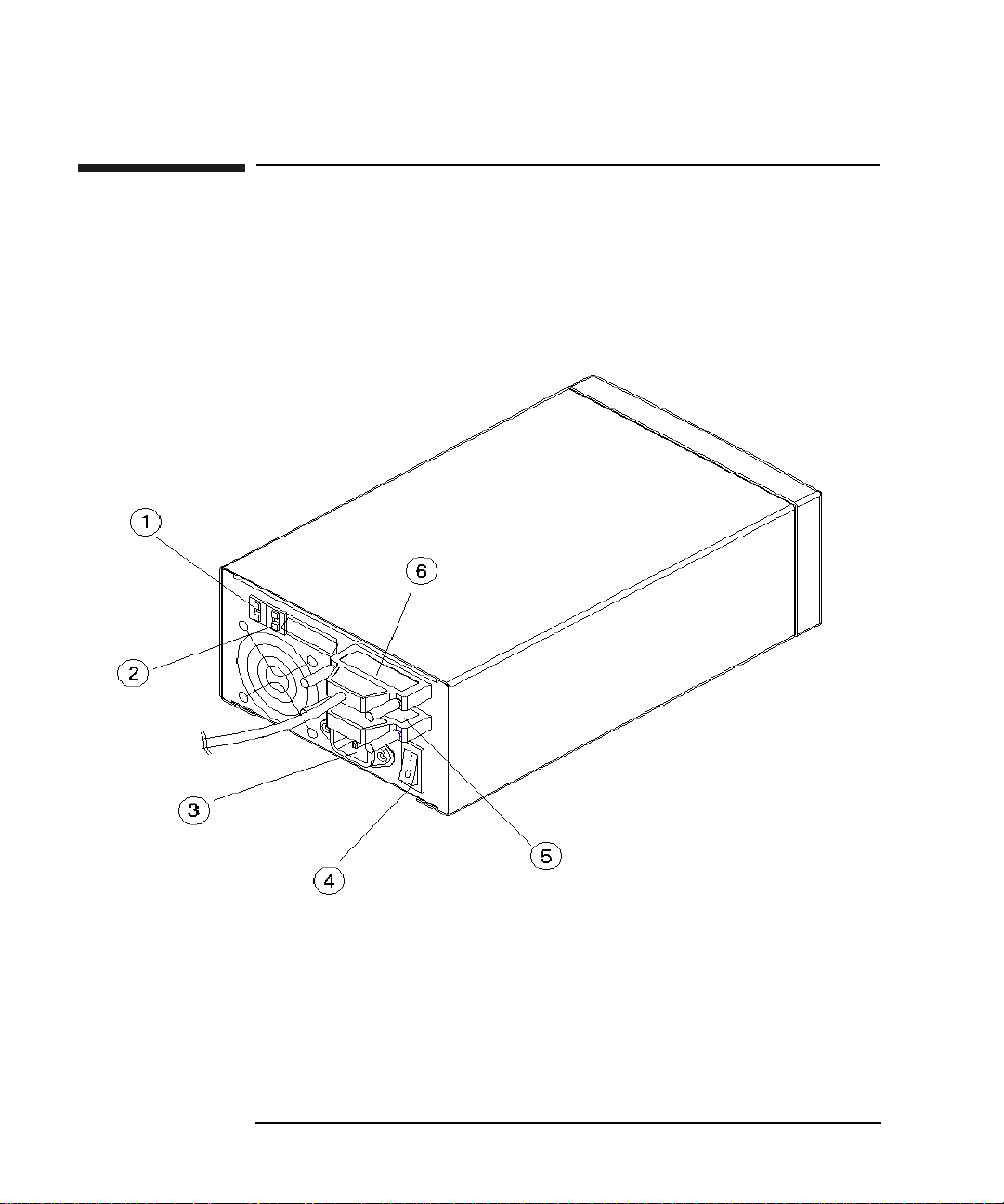
Figure 1-1 Rear Panel Features
1-4 Chapter 1
Page 15

Setting up the Disk Drive
Rear Panel Features
The following numbers correspond to the numbers in the drawing on the previous
page.
1SCSI ID switch Used to set the SCSI ID. Refer to “Setting
the SCSI ID” in this section.
2 Operation mode switch Used to choose the operating mode and set
your preference for write verify. Refer to
“Setting the Operation Mode” in this
section. 3 Power connector Receptacle for the power cord. 4 On/Off swit ch Used to switch pow er on or off.
Chapter 1: Setting
up the Disk Drive
Setting up the
Disk Drive
5 SCSI connector (with
terminator attached)
6 SCSI connector (with
cable attached)
50-pin high-density SCSI connector
(Micro D-type). Terminator may be
attached to either connector (see “6”).
A terminator must be plugged into either
“5” or “6” when the drive is the last
physical device on a SCSI bus.
50-pin high-density SCSI connector
(Micro D-type). Cable may be attached to
either connector (see “5”).
A terminator must be plugged into either
“5” or “6” when the drive is the last
physical device on a SCSI bus.
Chapter 1 1- 5
Page 16

Setting up the Disk Drive
Connecting the Drive to Your Host Computer
Connecting the Drive to Your Host Computer
The disk drive is a “narrow,” single-ended SCSI-2 device. This means that the drive
connects to a 50-line single-ended-type SCSI bus using 50-pin high-density
connectors.
You can connect the drive to a SCSI bus either as the only device on the bus or as
one of a number of devices on the bus (daisy-chained).
The SCSI ID you choose for this drive identifies the drive on the bus and also sets its
priority for use of the bus. If you would like more info rmat ion on the operat ion of
the SCSI bus, refer to Appendix B . Also, refer to y our hos t adapte r’s d ocument ation
for guidance on installing this drive on the b us .
The following sections will describe the steps to install this drive onto the bus. You
must do the following:
• Determine and set the drive’s operating mode
• Determine and set the SCSI ID of the drive
• Attach the bus cable and ensure the bus is properly terminated
Setting the Operating Mode and Write Verify
This drive may be operated in two modes :
• as an optical memory device
• as a direct access device
In most cases, you can select the optical memory device mode (which is the default
setting). Choose the “direct access device” mode if your system does not support
optical memory devices or if your system requires a direct access device. Check
your system documentation to d e termine which mode to select.
In either mode of operation, you have the choice of write verify on or off.
The write verify configuration ensures that data is written reliably to an optical disk.
The drive ships with write verify enabled. Many software appl ications also default
to this method of writing.
Writing data on a magneto-optical disk requires two passes. The first pa ss erases the
data in the sector to which data will be written. The second pass writes new d ata to
that sector.
1-6 Chapter 1
Page 17

Setting up the Disk Drive
Connecting the Drive to Your Host Computer
When write verify is configured to ON, an additional pass is made over the sector.
This third pass verifies that all data is written correctl y to the sector. To add to the
reliability of your data, Hewlett-Packard recommends that you maintain the default
ON setting for write verify. Note that when write verify is ON, write operations take
more time.
To set the device mode and the write verify mode:
1. Determine which operating mode you need (optical memory device or direct
access device) and whether you want write verify ON or OFF.
The following are the selections available on the mode switch:
• 2 - optical memory device with write verify ON (default).
• 0 - optical memory device with write verify OFF.
• 1 - direct access device with write verify OFF.
• 3 - direct access device with write verify ON.
2. Set the operating mode.
Chapter 1: Setting
up the Disk Drive
Setting up the
Disk Drive
a. Locate the operation mode switch on the rear panel of the disk drive (see “2”
on Figure 1-1).
b. Set the operation mode by pushing the button on the top or bottom of the
window (as explained below) with a small screwdriver or the point of a pen:
• the button above the mode window decreases the number by one
• the button below the mode window increases the number by one
NOTE If you change the op eration mod e with power on, you must power cy cle the drive for
the mode to take effect.
Setting the SCSI ID
CAUTION Before disconnecting power to any device on the SCSI bus, make sure the bus is
inactive. Switching off power while the SCSI bu s is active can result in data loss
or indeterminate bus states.
1. Turn drive power OFF (“4” on Figure 1-1).
2. Check which SCSI addresses are available. Usually the host bus adapter is set to
7 and the addresses available are in the range 0 to 6.
The default SCSI ID setting of this drive is 4.
Chapter 1 1- 7
Page 18

Setting up the Disk Drive
Connecting the Drive to Your Host Computer
3. Locate the SCSI ID switch on the rear panel of the disk drive (see “1” on Figure
1-1.
4. Set the SCSI ID by pushing the button at the top or bottom of the window (as
explained below) with a small screwdriver or the point of a pen:
• the button above the ID window decreases the number by one
• the button below the ID window increases the number by one
NOTE If you change the SCSI ID with power on, you must power cycle the drive so that
the host recognizes the new ID.
Cabling and Termination
NOTE This drive is a SCSI “fast” device. The maximum allowable length of the SCSI
cable cannot exceed 3 meters (4.9 feet), including the internal cable length of all
peripherals on the bus.
Use 0.5 meter (1.6 ft) as the internal SCSI cable length of this drive.
1. Plug one end of the power cord into the AC line connector on the back of the
optical disk drive and the other end into the power outlet.
2. Press the power switch on the rear of the optical disk drive so that it is in the
“ON” position (press “1”).
3. Switch on the power to the host computer (or if the host computer has been on
during this installation, powercycle the host computer so that it will “see” this
disk drive.
NOTE For some host computers to recognize the optical disk drive, the power to the disk
drive must be switched on before the power to the host computer.
4. Install the drivers appropriate for your host operating system.
The Software Architects drivers shipped with this drive enable you to read and
write 8X disks with the following operating systems:
• MAC OS8
• DOS
• Windows 3.1 and Windows 95
• Windows NT 3.51 and 4.0
1-8 Chapter 1
Page 19

Connecting the Drive to Your Host Computer
NOTE A few platforms provide native support for this drive.
A current list of platforms supporting this drive and platform-specific instructions
for connecting the drive to the host computer system are in:
www.hp.com/isgsupport/optical/index.html.
Setting up the Disk Drive
Chapter 1: Setting
up the Disk Drive
Setting up the
Disk Drive
Chapter 1 1- 9
Page 20

Setting up the Disk Drive
Configuring to an HP-UX 10.2 / 11.0 Host
Configuring to an HP-UX 10.2 / 11.0 Host
Obtaining HP-UX Patches
Your HP-UX system may require software patches to ensure that the 5200 ex will
install and operate correctly with your system.
If you have access to the World Wide Web, do the following steps:
1. Browse the following URL on the World Wide Web to determine and record
which (if any) patches are required for your system:
http://www.hp.com/go/optical
2. Download the required patch IDs from the following URL:
USA
http://us-support.external.hp.com
EUROPE
http://europe-support.external.hp.com
If you do not have access to the World Wide Web, do the following steps:
1. To obtain the current list of patches needed for Hewlett-Packard optical
products, send email to:
ssdg_tech_sup@hpgrla.gr.hp.com
Subject: (none)
Text: (none)
2. To receive instructions for downloading required HP-UX patches via email,
send an email message to:
support@support.mayfield.hp.com
Subject: (none)
Text: send guide.txt
3. Download the patches via email from the HP Support Line HP-UX email patch
server using the simple instructions in the user’s guide received in response to
the email request in Step 2.
1-10 Chapter 1
Page 21

Setting up the Disk Drive
Configuring to an HP-UX 10.2 / 11.0 Host
Configuring the Drive in a 10.2 / 11.0 System
Use the System Administration Manager (SAM) to configure the 5200ex to an
HP-UX 10.0 host system:
1. Log into your host system as superuser, then type sam.
2. Highlight and select Disks and File Systems.
3. Highlight and select Disk Devices.
4. Highlight the optical disk drive. (SAM calls it a "SCSI Optical Disk Drive”.)
5. Choose Add. .. an d N ot Us i ng L o gic Vol u me Manager from the “Actions” menu.
Your HP-UX system configuration now includes the optical disk drive.
Chapter 1: Setting
up the Disk Drive
Setting up the
Disk Drive
Chapter 1 1-11
Page 22

Setting up the Disk Drive
Configuring to an HP-UX 10.2 / 11.0 Host
1-12 Chapter 1
Page 23

Optical Disks
Using
2 Using Optical Disks
Page 24

Using Optica l Disks
Overview of This Chapter
Overview of This Chapter
Using Optical Disks
The optical disks that you use with this drive are an integral part of the storage
process. This chapter provides information on the follo wing topics:
choosing an optical disk type
•
• labeling optical disks
• write-protecting optical disks
• caring for optical disks
NOTE The optical cartridges used in this drive are a critical part of reliable data storage.
Optical cartridges consist of an opto-magnetic medium and mechanical components.
Consistent quality of opto-magnetic media ensu res correct “writes” and “reads.”
The quality and fit of the mechanical components of the cartridge affect accurate,
smooth handling of the cartridge by the drive. A failure of the mechanical
components of a cartridge could damage the drive mechanism.
CAUTION Use only HP-qualified media cartri dge s. Use of no n-HP-qu a li fie d op tical cartri dg es
could damage the drive and void the warranty.
NOTE A list of Hewlett-Packard optical media cartridges is in Table A-1 of Appendix A.
If you are not using HP media, please refer to the list of HP-qualified manufacturers
on the website:
www.hp.com/isgsupport/optical/index.html
2-2 Chapter 2
Page 25

Using Optical Disks
Choosing an Optical Disk Type
Choosing an Optical Disk Type
Two disk types can be used in this drive: rewritable disks and write-once disks.
To choose which type of disks to use, consider these points:
• Rewritable optical disks--data can be repeatedly written and erased.
• Write-Once optical disks--data can be written only once, and the data cannot be
altered or erased. If you have a need for data security an d audit tr ails, write-once
disks may be a good disk choice.
• Both rewritable and write-once disks come in three sector sizes: 2,048
bytes/sector, 1,024 bytes/sector, and 512 bytes/sector. The sector size you
choose depends upon what type of operating system you have in your host
computer.
NOTE Do not use write-once disks in a computer system that does not support write-once
disks. Check that your application software supports write-once disks.
Optical Disks
Using
Chapter 2 2-3
Page 26

Using Optica l Disks
Labeling an Optical Disk Cartridge
Labeling an Optical Disk Cartridge
Make it a practice to label your optical disk cartridges. You are provided adhesive
labels with each disk for this purpose. Here are some suggestions for labeling:
• date of format or initialization
• disk owner (group, department, etc.)
• storage purpose (backup, old version of operating system, etc.)
HP recommends using end labels as shown in Figure 2-1. End labels reduce the
chance of label material interfering with the cartridge shutter and causing a drive to
jam.
CAUTION Labels used in the vicinity of the shutter may cause the drive to jam if the label is
installed incorrectly or if portions of the label lift off because of wear. If a drive
jams because the label interferes with the shutter the drive may have to be serviced.
Figure 2-1 Recommended Placement of Cartridge Labels
2-4 Chapter 2
Page 27

Using Optical Disks
Write-Protecting an Optical Disk
Write-Protecting an Optical Disk
Each side of an optical disk can be write-protected by sliding the write-protect
button in the direction of the arrow on the cartridge (see Figure 2-2).
With rewritable optical disks, write-protecting the disk prevents overwriting
existing files and prevents any additional file being written to the disk.
With write-once optical disks, existing files cannot be altered or erased regardless of
whether or not the write-protect button has been set. However, setting the button to
write-protect prevents writing additional files to the disk.
Figure 2-2 Write-Protect Button Location
Optical Disks
Using
Chapter 2 2-5
Page 28

Using Optica l Disks
Caring for Optical Disks
Caring for Optical Disks
Follow these guidelines to ensure that your optical disks remain in good condition:
• Do not expose disks to extreme magnetic fields.
• Do not expose disks to dust particles.
• Do not expose disks to extreme temperatures or extreme humidity.
• Do not drop the disks.
• Do not open a disk's metal shutter and touch the disk surface.
• Do not take disks apart.
• Do not insert disks with loosely-attached labels into the drive.
• Remove old disk labels before applying new ones especially if you choose to
place labels on the sides of the cartridge (near the shutter) rather than on the en d
of the cartridge.
• Store disks in a clean, safe place when they are not in use.
Cleaning Disks
Normally, an optical disk does not require cleaning when used in a computer room
or clean office environment. If you are in an extremely dusty environment and are
experiencing difficulties reading and/or writing to a particular disk you may want to
clean the disk to see if this corrects the problem.
CAUTION Be very careful when cleaning an optical disk. Abrasive particles dragged acro ss the
disk surface can damage the disk and prevent recovery of some or all of the data on
the disk.
Clean a disk only with a disk cleaning kit. Follow the disk cleaning kit instructions
exactly.
The order numbers for manual and automated disk cleaning kits are in Table A-1,
Appendix A.
2-6 Chapter 2
Page 29

3 Operating the Disk Drive
Operating the
Disk Drive
Page 30

Operating the Disk Drive
Operating the Disk Drive
Operating the Disk Drive
This chapter explains the features used to operate the disk drive.
Figure 3-1 Front Panel Features
3-2 Chapter 3
Page 31

Operating the Disk Drive
Identifying Front Panel Features
Identifying Front Panel Features
The following list of features corresponds to the numbers in Figure 3-1:
1) Disk slot The opening for inserting/retrieving optical disks
2) Activity indicator Lit when the drive is accessed and while the drive is loading or ejecting a disk.
3) Power indicator Remains lit while the power is on
4) Eject tool opening An access hole for the eject tool. In an emergency , such as a power outage, the disk can be manually ejected by inserting the eject tool into this
opening. See “Manually Ejecting Disks” on the
next page.
5) Eject button Pressed to eject the disk from the drive. The drive power must be ON.
Operating the
Disk Drive
Chapter 3 3- 3
Page 32

Operating the Disk Drive
Loading a Disk Into the Drive
Loading a Disk Into the Drive
NOTE Use only the highest quality media in this driv e. A list of guaranteed
Hewlett-Packard media is in Table A-1 in Appendix A.Optical cartridges use both
opto-magnetic media and mechanical components. A failure of the mechanical
components of a cartridge could damage an optical drive and void the warranty.
If you are not using HP media, please refer to the list of HP-qualified manufacturers
on the website:
www.hp.com/isgsupport/optical/index.html
Insert the disk gently but firmly into the opening on the front panel, shutter end first,
and with the side you want to access facing up (A or B).
The drive automatically pulls the di sk fully into position.
Ejecting a Disk Using the Disk Eject Button
Press the eject button to the right of the disk slot (see “5” on Figure 3-1).
Manually Ejecting Disks With Power Off
The drive does not automatically eject a disk cartridge if a power failure occurs. An
eject tool is shipped with the drive to use for manually ejecting a disk.
Follow these steps to manually remove a disk from the drive:
1. Disconnect all power to the drive.
2. Insert the eject tool into the small round hole in the fron t panel of the drive (see
“4” on Figure 3-1).
3. Push the eject tool firmly. The disk will eject.
NOTE After ejecting a disk, the drive remains in “eject position” until power is restored. At
that time, the drive automatically resets itself.
3-4 Chapter 3
Page 33

Operating the Disk Drive
Troubleshooting
Troubleshooting
Problem What to Do
Drive will not
power on • Check that the power indicator light on the drive front panel
is ON (“3” on Figure 3-1).
If light is not ON, make sure the power switch on the rear
panel is ON.
• Check that the cooling fan is running (on rear panel).
If the fan is not running, check that the power cord is
connected and tight and the power outlet is
operating. If the power cord is tight and the outlet
is operating, replace the power cord with a known
good one.
• If steps above are unsuccessful, refer to Appendix A for
further support services.
Operating the
Disk Drive
Chapter 3 3- 5
Page 34

Operating the Disk Drive
Troubleshooting
Problem What to Do
Host computer
system does not
recognize the drive • Ensure the disk is connected and ON. (The disk must b e ON
when booting the host computer for the disk to be
recognized.
The following steps attempt to bring the disk online without
booting the host computer system.
• In Windows 95 and NT, rescan the bus.
- go to My Computer, Control Panel, System,
Device Manager (in 95), and SCSI
Controllers. Select the SCSI adapter where the
drive should be. Select Refresh.
• In HP-UX, use SAM to verify that the drive is on the bus
and, if not, use SAM to install the driver.
- Follow the menus in SAM
• For Unix systems other than HP-UX, refer to the System
Administrators Guide for diagnosing missing peripherals.
• If the drive is the last one on the SCSI bus, check that the
drive has an terminator plugged into one of the cable
connectors (an active terminator is recommended).
• Check SCSI ID assignments and resolve any conflict.
• If steps above are unsuccessful, further information may be
on the optical web site at
www.hp.com/isgsupport/optical/index.html
• If an answer is not on the web site, go to Appendix A for
further support informati on.
3-6 Chapter 3
Page 35

Operating the Disk Drive
Troubleshooting
Problem What to Do
Other SCSI
devices no longer
work when this disk
is installed • There is probably a conflict in SCSI IDs. Check ID
assignment
• Refer to the instructions for your host adapter and review
installation of devices on the bus.
Unable to read from
a disk • Check power and connections. See “Drive won’t power on”
discussed previously in this table
• Does the host computer recognize the drive on the bu s? See
“Host system does not recognize the drive” discussed
previously in this table.
• Does the host computer recognize the drive on the bu s? See
“Host system does not recognize the drive” discussed
previously in this table.
• Does the disk have a valid file system?
Operating the
Disk Drive
-If the disk does not have a valid file system,
you must form at the disk (Windows 95, NT) or
do a media init (HP-UX). For other Unix
systems, refer to your System Administrator’s Guide to
prepare the disk.
• Is write verify enabled to ensure that information is being
correctly written to the disk?
Continued on the next pag e
Chapter 3 3- 7
Page 36

Operating the Disk Drive
Troubleshooting
Problem What to Do
Unable to read from a disk (continued) • Can you read from another disk?
• If in Windows 3.x, does your application support 1,024
bytes per sector media?
• If in Windows 95 or NT and using 1,024 bytes per sector
disks, boot your system with this density disk in the drive.
• Is the environment dusty? If you are not having the same
problems with other disks, you may want to clean the disk.
See “Cleaning Disks” at the end of Chapter 2.
• If steps above are unsuccessful, further information may be
on the optical web site at
www.hp.com/isgsupport/optical/index.htm
• If an answer is not on the web site, go to Appendix A for
further support informati on.
3-8 Chapter 3
Page 37

Operating the Disk Drive
Troubleshooting
Problem What to Do
Unable to write to a
disk • Check power and connections. See “Drive won’t power on”
discussed previously in this table.
• Does the host computer recognize the drive on the bu s? See
“Host system does not recognize the drive” discussed
previously in this table.
• Is there a valid file system on the disk?
• If the disk does not have a valid file system,
you will receive an error message.
• If the disk does not have a valid file system,
you must format the disk (Windows 95, NT) or
do a media init (HP-UX). For other Unix
systems, refer to your System Administrator’s
Guide to prepare the disk.
• Is the disk one of the following capacities: 2.3, 2.6, 4.6, or
5.2 gigabytes? This drive writes to only thes e capacities.
• If in Windows 3.x and using 1,024 bytes/sector disks—
refer to your application documentation to verify that your
application supports this sector density.
• If in Windows 95 or NT and using 1,024 bytes/sector
disks— boot your system with this density disk in the drive.
Continued on the next pag e
Operating the
Disk Drive
Chapter 3 3- 9
Page 38

Operating the Disk Drive
Troubleshooting
Problem What to Do
Unable to write to a disk (continued) • Eject the disk and check that the disk is a rewritable disk
and that the write-protect tab is in the “write” position.
• Try writing to another, similar disk.
• Is the environment dusty? If you are not having the same
problems with other disks, you may want to clean the disk.
See “Cleaning Disks” at the end of Chapter 2.
• If steps above are unsuccessful, further information may be
on the optical web site at
www.hp.com/isgsupport/optical/index.html
• If an answer is not on the web site, go to Appendix A for
further support informati on.
Disk “reads” are
slow • Is the environment dusty? If you are not having the same
problems with other disks, you may want to clean the disk.
See “Cleaning Disks” at the end of Chapter 2.
• If cleaning does not correct the problem, fur ther information
may be on the optical web site at
www.hp.com/isgsupport/optical/index.html
• If an answer is not on the web site, go to Appendix A for
further support informati on.
3-10 Chapter 3
Page 39

Operating the Disk Drive
Troubleshooting
Problem What to Do
Disk “writes” are
slow • Is write verify enabled? The verification pass increases the
write time.
• Is the environment dusty? If you are not having the same
problems with other disks, you may want to clean the disk.
See “Cleaning Disks” at the end of Chapter 2.
• If cleaning does not correct the problem, fur ther information
may be on the optical web site at
www.hp.com/isgsupport/optical/index.html
• If an answer is not on the web site, go to Appendix A for
further support informati on.
Host adapter does
not work with this
drive Check that SCSI IDs for the host adapter and the drive are
different.
The SCSI
connector on the
host computer and
drive are different Get a cable with the correct connector types. See table A-1 in
Appendix A for cables offered by Hewlett-Packard.
Operating the
Disk Drive
If the suggestions in the troubleshooting table do not solve the problem, try
accessing the HP web site at www.hp.com/isgsupport/optical/index.html for the
latest information and frequently asked questions. If information from the website is
not enough, refer to Appendix A for further support services available to you
Chapter 3 3-11
Page 40

Operating the Disk Drive
Troubleshooting
3-12 Chapter 3
Page 41

A Supplies and Customer Support
Customer Supp ort
Supplies and
Page 42

Supplies and Customer Support
Supplies and Customer Support
Supplies and Customer Support
This section provides information on th e following topics
• supplies and accessories
• HP customer support
Supplies and Accessories
A full range of computer supplies may be ordered through a Hewlett-Packard
authorized dealer or sales office, or by phoning or writing HP Direct.
Call 1-800-752-0900 for the location of your nearest authorized Hewlett-Packard
dealer.
To contact a Hewlett-Packard sales representative, see Table A-2 for a list of
addresses and phone numbers of HP sales offices.
To phone HP Direct call 1-800-538-8787; or write to HP Direct at the following
address:
HP Direct
Hewlett-Packard
P.O. Box 58195
Santa Clara, California 95052
See Table A-1 for a list of basic supplies and accessories
Table A-1 Basic Supplies and Accessories
Item HP Part Number
5.2- and 4.7-Gbyte Optical Disks
Rewritable optical disk (2,048 bytes/sector, 5.2
Gbytes, single disk)
Rewritable optical disk (2,048 bytes/sector, 5.2
Gbytes, 8-pack)
Write-once optical disk (2,048 bytes/sector, 5.2
Gbytes, single disk)
A-2 Appendix A
88147J
C6299J
88146J
Page 43

Supplies and Customer Support
Supplies and Customer Support
Item HP Part Number
Write-once optical disk (2,048 bytes/sector, 5.2
Gbytes, 8-pack)
Rewritable optical disk (1,024 bytes/sector, 4.7
Gbytes, single disk)
Rewritable optical disk (1,024 bytes/sector, 4.7
Gbytes, 8-pack)
Write-once optical disk (1,024 bytes/sector, 4.7
Gbytes, single disk)
Write-once optical disk (1,024 bytes/sector, 4.7
Gbytes, 8-pack)
2.6- and 2.3-Gbyte Optical Disks
Rewritable optical disk (1,024 bytes/sector, 2.6
Gbytes, single disk)
Rewritable optical disk (1,024 bytes/sector, 2.6
Gbytes, 8-pack)
Write-once optical disk (1,024 bytes/sector, 2.6
Gbytes, single disk)
Write-once optical disk (1,024 bytes/sector, 2.6
Gbytes, 8-pack)
C6298J
88143J
C2589J
88145J
C2591J
92280F
C2589F
92290F
C2591F
Customer Support
Supplies and
Rewritable optical disk (512 bytes/sector, 2.3
Gbytes, single disk)
Rewritable optical disk (512 bytes/sector, 2.3
Gbytes, 8-pack)
Write-once optical disk (512 bytes/sector, 2.3
Gbytes, single disk)
Write-once optical disk (512 bytes/sector,2.3
Gbytes, 8-pack)
Appendix A A-3
92279F
C2588F
92289F
C2590F
Page 44

Supplies and Customer Support
Supplies and Customer Support
Item HP Part Number
SCSI Cables
50-Pin Low-Density to 50-Pin High Density, male- to-male
1.0 m (3.3 ft.) bail to thumb screw K2296
1.5 m (4.9 ft.) bail to thumb screw K2297
0.9 m (2.9 ft.) thumb screw to thumb screw K2294
1.5 m (4.9 ft.) thumb screw to thumb screw K2295
SCSI Terminators
50-pin active high-density (molded) C2904A
Disk Cleaners
RA-2 Manual Disk Cleaner
ProDisk Corporation
US Tel.(612) 439-6202 Fax (612) 439-5946
(approximately US$3 0)
KA-1 Automatic Disk Cleaner
ProDisk (see above)
(approximately US$5 59 )
Documents
User’s Guide (replacement or additional) C1114-90015
N/A
N/A
A-4 Appendix A
Page 45

Supplies and Customer Support
Hewlett-Packard Customer Support
Hewlett-Packard Customer Support
If your drive fails during the warranty period, and the suggestion s in this user’s
guide and accompanying documentation do not solve your problem:
• Consult the Quick FAX or HP FIRST (FAX information Retrieval Support
Technology) facsimile assistance services.The phone numbers are under
“Faxback Services” on the next page.
• Consult one of the computer/modem connectivity services available, such as
America Online or CompuServe. The phone numbers are under “Electronic
Support Services” later in this appendix.
• Contact your authorized HP dealer distributor
NOTE Before calling, please record the following information and have it ready when you
contact your service representative:
- model number of the drive
- serial number of the drive
Customer Support
Supplies and
- brand and model of your host computer SCSI adapter
- host computer operating system
- any software package you are using to manage storage on the drive
Should you need additional support, call the Custom er Supp ort C enter in your
region. FAX, electronic services and support center numbers are given on the
following pages.
If your drive fails after the warranty period, contact your authorized HP
dealer/distributor or the nearest HP sales and service office. Customers in the US
and Europe can use a credit card for phone assistance. For details, see “Telephone
Support After Warranty” in this appendix.
Faxback Services
Quick FAX and HP FIRST are automated systems that FAX requested product
information and/or technical support documents to you. These faxback services are
available 24 hours.
Appendix A A-5
Page 46

Supplies and Customer Support
Hewlett-Packard Customer Support
Simply dial the FAX number from a touch tone telephone or Grou p 3 facsimile
machine and follow the voice prompts that guide you to select an index of available
support an product documents.
Asia-Pacific
Australia (03) 9272 2627 China (8610)-6505 5280 Hong Kong 2506 2422 India +91 11 682 6041 Indonesia (21) 352 2044 Japan (3) 3335-8622 Korea (02) 769-0543 Malaysia (03) 290 2478 Netherlands 0800 22 2420 New Zealand (09) 356 6642 Singapore (65) 291-7951 Taiwan (02) 719 5589
Thailand (02) 661 3511 Europe
Austria 0660 8128 Belgium
Dutch 0800 11906
French 800 17043 Denmark 800 10453 Finland 0800 13134 France 05 905900
A-6 Appendix A
Page 47

Germany 0130 810 061 Italy 1678 59020 Netherlands 06 022 2420 Norway 800 11319 Spain 900 993123 Sweden 020 795743 Switzerland
German 0800 55 1526 French 0800 55 1527
United Kingdom 0800 960271
Supplies and Customer Support
Hewlett-Packard Customer Support
Other locations in
Europe
(toll line)
North and South America and Canada
All other countries (to the US )
+31 20 681 5792
(800) 368-9673 or (970) 635-1510
(970) 635-1510
Electronic Support Services
For 24-hour access to information over your modem, refer to the following listings.
On-line Service Providers
Technical information is available on CompuServe and America Online.
(Compuserve and America Online are not operated by Hewlett-Packard.)
CompuServe HP systems Forum, Go HPSYS America Online HP forum, Go HPSTOR
Customer Support
Supplies and
Appendix A A-7
Page 48

Supplies and Customer Support
Hewlett-Packard Customer Support
AccessHP and Support on the World Wide Web
Product and support information is available on the Hewlett-Packard web site:
Product information - www.hp.com
Support - www.hp.com/isgsupport/optical/index.html
Telephone Support During Warranty
To speak with someone for technical assistance within the hardware warranty of
your product, call a support representative at the location appropriate to your
location as listed below.
NOTE Before calling, please record the following information and have it ready when you
contact your service representative:
- model number of the drive
- serial number of the drive
- brand and model of your host computer SCSI adapter
- host computer operating system
- any software package you are using to manage storage on the drive
US - America’s Customer Support Center
Monday - Friday, 7am - 5pm Mountain Time (970) 635-1000
Europe - European Customer Support Center
Monday - Friday, 8:30am - 5pm Netherlands Time
Austria 0660 6386 Germany 0180 5 25 81 43 Belgium Netherland 020 606 8751
Dutch 02 626 8806 Norway 22 11 6299
French 02 626 8807 Portugal 01 441 7199 Denmark 3929 4099 Spain 902 321 123 Finland 0203 47288 Sweden 08 619 2170
A-8 Appendix A
Page 49

Supplies and Customer Support
Hewlett-Packard Customer Support
France 04 50 43 9853 Switzerland 0848 80 11 11 Ireland 01 622 5525 United
Kingdom
Italy 02 26410350
0171 512 5202
English language support from other European countries:
+44 171 512 5202
Asia-Pacific - HP Customer Support Center
Australia 8:30 - 17:30 Mon-Fri (03) 9272-8000 China 8:30 - 17:30 Mon-Fri (8610) 62625666
x5602, 5609, 5611, 5612
(8610) 62 61 4174
(8610) 62 61 4175
(8610) 62 61 4176
Japan 9:00 - 1200
13:00 - 17:00 Mon-Fri
Korea 8:30 - 1900 Mon-Fri (02) 3270-0700/
(3) 3335-8338
080-999-0700 (toll free)
Customer Support
Supplies and
New Zealand
Singapore 9:00 - 17:00 Mon - Fri (65) 271-7233 Taiwan 8:30 - 17:30 Mon - Fri (02)717-9609
8:30 - 16:00 Wed AEST (09) 356-6640
Elsewhere in the World to the US
(970) 635-1000
Appendix A A-9
Page 50

Supplies and Customer Support
Hewlett-Packard Customer Support
Telephone Support After Warranty
NOTE Before calling, please record the following information and have it ready when you
contact your service representative:
- model number of the drive
- serial number of the drive
- brand and model of your host computer SCSI adapter
- host computer operating system
- any software package you are using to manage storage on the drive
North and South America and Canada
Using your VISA, MasterCard, or American Express call:
(800) 810-0130 - Per incident fee of $25.00 charged to your credit card.
(900) 555-1800 - $2.50 per minute up to a maximum of $25.00 per incident. You
must be 18 years of age or have parental permission to call this number.
Prices are subject to change without notice.
Europe
Call the numbers listed in the “Telephone Support Under Warranty” section. A per
incident fee will be charged for after warranty support. Please have a credit card, PO
number, or billing address ready.
Elsewhere in the World
Contact your authorized HP dealer/distributor or the nearest HP sales and service
office.
Additional Telephone Support
Singapore Customer Care-Line for End-Users (65) 272-5300
A-10 Appendix A
Page 51

Supplies and Customer Support
Hewlett-Packard Customer Support
HP Reseller Locator Numbers
US (800) 752-0900 Canada (800) 387-3867 Mexico and South America (305) 267-4220
Customer Support
Supplies and
Appendix A A-11
Page 52

Supplies and Customer Support
Warranty
Warranty
HP PRODUCT DURATION OF WARRANTY
C1114J One Year
1. HP warrants HP hardware, accessories and supplies against defects in materials
and workmanship for the period specified above. If HP receives notice of such
defects during the warranty period, HP will, at its option, either repair or replace
products which prove to be defective. Replacement products may be either new or
like-new.
2. HP warrants that HP software will not fail to execute its programming
instructions, for the period specified above, due to defects in material and
workmanship when properly installed and used. If HP receives notice of such
defects during the warranty period, HP will replace software media which does not
execute its programming instructions due to such defects.
3. HP does not warrant that the operation of HP products will be uninterrupted or
error free. If HP is unable, within a reasonable time, to repair or replace any product
to a condition as warranted, customer will be entitled to a refund of the purchase
price upon prompt return of the product.
4. HP products may con tain rema nufactured parts equivalent t o n ew i n perf orman ce
or may have been subject to incidental use.
5. The warranty perio d b egi ns o n the date of deliver y or on the date of instal l at ion if
installed by HP. If customer schedules or delays HP installatio n more than 30 days
after delivery, warranty begins on the 31st day from delivery.
6. Warranty do es not apply to defects resulting from (a) improper or inadequate
maintenance or calibration, (b) software, interfacing, parts or supplies not supplied
by HP, (c) unauthorized modification or misuse, (d) operation outside of the
published environmental specifications for the product, or (e) improper site
preparation or maintenance.
7. TO THE EXTENT ALLOWED BY LOCAL LAW, THE ABOVE
WARRANTIES ARE EXCLUSIVE AND NO OTHER WARRANTY OR
CONDITION, WHETHER WRITTEN OR ORAL, IS EXPRESSED OR IMPLIED
AND HP SPECIFICALLY DISCLAIMS ANY IMPLIED WARRANTIES OR
CONDITIONS OF MERCHANTABILITY, SATISFACTORY QUALITY, AND
FITNESS FOR A PARTICULAR PURPOSE.
A-12 Appendix A
Page 53

Supplies and Customer Support
Warranty
8. HP will be liable for damage to tangible property per incident up to the greater of
$300,000 or the actual amount paid for the product that is the subject of the claim,
and for damages for bodily injury or death, to the extent that all such damages are
determined by a court of competent jurisdiction to have been directly caused by a
defective HP product.
9. TO THE EXTENT ALLOWED BY LOCAL LAW, THE REMEDIES IN THIS
WARRANTY STATEMENT ARE CUSTOMER’S SOLE AND EXCLUSIVE
REMEDIES. EXCEPT AS INDICATED ABOVE, IN NO EVENT WILL HP OR
ITS SUPPLIERS BE LIABLE FOR LOSS OF DATA OR FOR DIRECT,
SPECIAL, INCIDENTAL, CONSEQUENTIAL (INCLUDING LOST PROFIT OR
DATA), OR OTHER DAMAGE, WHETHER BASED IN CONTRACT, TORT,
OR OTHERWISE.
Obtaining Service
To maintain the warranty, you must have your optical drive serviced by an
authorized repair depot in the country of original purchase. Return your optical drive
to a Hewlett-Packard Dealer Repair Center or a designated Hewlett-Packard Repair
Center. See the following pages for a list of designated Hewlett-Packard Repair
Centers.Contact your Hewlett-Packard Dealer Repair Center for instructions before
returning your optical drive for service. If you return your optical drive to a
designated Hewlett-Packard Field Repair Center for service, you must prepay all
shipping charges, duty, and taxes. E xcept for products retu rned to the customer from
another country, Hewlett-Packard will pay for return shipmen t to the custo mer.
Before you send your optical drive to a Hewlett-Packard Dealer Repair Center or a
designated Hewlett-Packard Field Repair Center, insure the optical drive and f ollow
the re-packing guidelines below. Enclose a completed Service Information Form ( on
the following page), a copy of proof of purchase.
Service After the Warranty Period Expires
If your optical drive fails after the warranty period, contact an authorized
Hewlett-Packard Dealer Repair Center or a designated Hewlett-Packard Repair
Center. If you have a Hewlett-Packard Maintenance Agreement, request service
under your agreement.
Repacking guidelines for returning your optical drive
1. Remove your optical disk from the drive.
Customer Support
Supplies and
2. Use the original shipping container and packing materials, if possible
Appendix A A-13
Page 54

Supplies and Customer Support
Warranty
3. Enclose the completed Service Information Form (inclu ded in this section).
Service Information Form
Make a photocopy of this form, complete it, and ship it with your equipment.
Service cannot begin until we have this information. Be sure you have followed the
repacking guidelines listed earlier in this section of the manual. You will be
returning your equipment to the HP Field R epair Cen ter or an authorized HP Dealer
Repair Center.
Who is returning this drive?
Company/Institution_____________________________________
____________
Date _____________
Person to Contact_________________________________Phone
_____________
Alternate
Contact_________________________________Phone___________
___
What is being sent?
Model Number_____________________ Serial Number ____________________
Have you included an optical disk? Yes_____ No ______
Returning Shipping Address:
__________________________________________________________________
__________________________________________________________________
How will you pay for the repairs?
Except for contract and warranty services, a credit card number or purchase order
number and authorized signature must acco mpan y any request for service. Standard
repair prices may be obtained by contacting a Repair Center.
Warranty: purchased/received date _______________________________
(Enclose proof of purchase or receiving document indicating original received date.)
A-14 Appendix A
Page 55

Supplies and Customer Support
Warranty
Maintenance Contract: number __________________________________
_____ VISA______ MASTER CARD _____AMERICAN EXPRESS
Credit Card Number_______________________________________________
Expiration Date___________________________________________________
Signature ____________________________________ Date _____________
Purchase order number:___________________
Billing Address:
________________________________________________________________
________________________________________________________________
Authorized Signature: ___________________________________________
Phone __________________________
What needs to be done?
Describe the conditions at the time of failure. (What were you doing when the
failure occurred? What software were you running? Is the failure repeatable?)
__________________________________________________________________
__________________________________________________________________
__________________________________________________________________
__________________________________________________________________
Additional comments:
___________________________________________________________________
___________________________________________________________________
___________________________________________________________________
___________________________
Thank you.
Customer Support
Supplies and
Appendix A A-15
Page 56

Supplies and Customer Support
Hewlett-Packard Service Centers
Hewlett-Packard Service Centers
Hewlett-Packard Service in the US
Before shipping the optical disk drive for service, call the Customer Support Center
at (970) 635-1000.
Hewlett-Packard Company
46732 Lakeview Boulevard
Fremont, California 94538-6534
Telephone (650) 694-3650
Hewlett-Packard Service Worldwide
Hewlett-Packard products are sold and supported worldwide through
Hewlett-Packard Sales and Service Offices and through dealers. There are more
than 240 Hewlett-Packard Sales and Service Offices worldwide.
For information about where to have your optical drive serviced, call one of the
following European Customer Support Center numbers first. Hewlett-Packard
regional offices are listed in the table, “HP Sales and Service Offices” on the next
page.
European Customer Support Center (+44) 171 512 5202 (English)
0180 5 25 81 43 (German)
04 50 43 9853 (French)
A-16 Appendix A
Page 57

B Operating This Drive on a SCSI Bus
Operating the Drive
on a SCSI Bus
Page 58

Operating This Drive on a SCSI Bus
A Brief Overview of SCSI
A Brief Overview of SCSI
General
The Small Computer System Interface (SCSI), is a contention-based bus that
accommodates different speed devices without impacting the devices with faster
transfer speeds. This specification was defined by the American National Standards
Institute (ANSI) in 1986. The specification defines both the physical medium and
the command set used to transf er inf orma tion. Late r d evelop ments are kno wn u nder
the newer specifications, SCSI-2 and SCSI-3.
The SCSI Bus
The common SCSI buses are 50-p in and 68-pin . The 50-pin bu s, which uses ei ght of
its lines for data transmission, is called a "narrow" bus. The narrow bus can support
eight devices. The 68-pin bus, which uses 16 lines for data transmission is called a
"wide" bus. The wide bus can support 16 devices.
Initiators and Targets
SCSI devices on the bus are either “initiators” or “targets.” An initiator (usually the
host computer) originates a transaction and the target (usually a peripheral device)
fulfills the request.
Initiators and targets identify themselves on the bus by a SCSI ID. The ID is
designated by the user and is set electronically or man ually depending on the device.
In addition to identifying a device on the bus, the ID also determines the priority of
the device during contention among the devices for use of the bus.
The narrow SCSI bus, with its eight data lines, can communicate with eight devices
that have IDs from 0 to 7. The wide SCSI bus, with its 16 data lines, can
communicate with 16 devices that have addresses from 0 to 15. The host adapter,
which links the host computer to the SCSI bus, is also a SCSI device (initiator), and
is usually assigned an ID of 7.
Priority of IDs ascends from lowest to highest but this ascending priority, however,
is in blocks of eight IDs, and the block from 8 to 15 is actually defined to be at a
lower priority than ID 0, the lowest address on the "narrow" portion of the bus. This
is done so that if a narrow device is placed on a wide bus, the wide devices, which
can "see" the lower addresses, will always defer to the lower addresses when they
contend for the bus. Otherwise, a narrow device, which cannot "see" any device at
B-2 Appendix B
Page 59

Operating This Drive on a SCSI Bus
A Brief Overview of SCSI
an ID greater than 7, would always assume it won the contention and would attempt
to talk, perhaps at the same time as a device with an ID above 7 th at was contending
for the bus. The following diagram shows the priority scale of IDs when the priority
of the two blocks of eight are reversed.
Priority
8 9 10 11 12 13 14 15 0 1 2 3 4 5 6 7
Narrow
Addresses
Wide Address Range
The diagram below shows the linear addressing of a simple, narrow bus with the
host adapter set at a SCSI ID of 7. The device ID does not determine where the
device is physically placed on the bus.
LUN Addressing
This drive does not support logical unit numbering (LUN) addressing
Transfer Rates on the Bus
Initially, the SCSI specification defined a 5 MB/s synchronous data transfer rate on
the narrow bus. SCSI now al so defines "F ast" whi ch is 10 MB/s on a narrow bu s and
20 MB/s on a wide bus. Another definition is "Ultra," also known as "Fast-20"
which is 20 MB/s transfer rate on a narrow bus and 40 MB/s on a wide bus.
Appendix B B-3
Operating the Drive
on a SCSI Bus
Page 60

Operating This Drive on a SCSI Bus
A Brief Overview of SCSI
Termination
To keep signals on the SCSI bus from being reflected, “terminators” must be placed
at each end of the physical bus. These terminators may be either active or passive.
Passive termination is a resistor network. Active termination uses a voltage
regulator (the active component) to regulate the power of the resistor network to
provide more stable termination. Active termination is always preferred over
passive termination.
Depending on your SCSI device, termination is supplied by a using a physical
connector, by flipping a dipswitch, or by selecting th e termi nation setting in
software.
Termination is always at both physical ends of the bus.
Single-ended and Differential Interfaces
(This drive does not support differential SCSI. The following description is here
only for comparison to single-ended SCSI, which the drive supports.)
The SCSI bus is electrically implemented in two ways: single-ended and
differential. These terms come from the way the signals are asserted on the bus.
Single-ended buses use a 5-volt signal that is referenced to ground. This method
makes the bus somewhat susceptible to noise and loss of signal quality over
distance. The maximum allowable length of a single-ended SCSI bus was initially 6
meters (19.7 feet). Fast SCSI requ ir ed t he maxi mu m l e ng th of the bus to be redu ced
to 3 meters (9.8 feet).
B-4 Appendix B
Page 61

Operating This Drive on a SCSI Bus
A Brief Overview of SCSI
The differential bus uses two lines for each signal and measures the voltage
difference between the two signals. Differential retains more signal q uality than
single-ended and is not as sensitive to noise, allowing for a longer cable len gth. The
maximum allowable length of a differential bus is 25 meters (82 feet) for all types
buses (narrow, wide, fast, Fast-20).
Connectors
Narrow devices (50-pin) use the following connectors:
• 50-pin low-de nsity clip Centronics-type (external)
This is a large connector that is similar to a printer cable. This type of connector
is gradually being replaced by the Micro D connector, described below.
• 50-pin high density Micro D (using thumbscrews or small clips) (external)
• This connector is similar to a D-type connector, but smaller and with smaller pin
holes placed closer together.
• 50-pin low-density ribbon (usually internal to the host)
Wide devices (68- pin) use the following connectors:
• 68-pin high density Micro D connector (external)
This connector is similar to a D-type connector, but longer and slimme r and with
smaller pin holes placed closer together. This connector is becoming the most
common.
• 68-pin high density ribb on (usually internal to the host)
NOTE For more complete information on the theory and operation of the SCSI bus, you
may want to go to:
Adaptec - major supplier in SCSI buses
www.adaptec.com
Symbios Logic - Working drafts of SCSI specifications
www.symbios.com/x3t10
Appendix B B-5
Operating the Drive
on a SCSI Bus
Page 62

Operating This Drive on a SCSI Bus
The SCSI Bus and This Drive
The SCSI Bus and This Drive
This drive is a “fast and narrow” SCSI device that uses a single-ended SCSI bus.
When deciding on whether to have multiple devices on the same SCSI bus, you
should consider the following:
• How are the devices going to be used? What performance is expected from each
device?
• If the decision is made to have multiple devices on the same bus , what SCSI
requirements must be observed to make sure the bus will wo rk?
Consider the quantity of data that the bus will have to carry, the frequency of data
transfer, and the priority of this data transfer in your business. If you expect to be
using the drive in the same time-frame as another device, or devices, you may
experience a drop in performance.
Mixing Wide and Narrow Devices
An a preliminary note to this discussion, HP highly recommends that you do NOT
mix wide and narrow buses.
Connecting devices of the same bus width, such as all narrow (50-pin) is a simple
process of daisy-chaining the devices, and terminating both ends of the bus.
However, mixing narrow and wide devices invites problems.
This method should only be implemented by an experienced systems integrator who
is highly knowledgeable about SCSI. Since the wide (68-pin) buses need more data
lines on the bus for their data transfer, it's necessary that the cables connecting the
devices are 68 pin. The data would be lost if the devices were set up as depicted in
the figure below.
B-6 Appendix B
Page 63

Operating This Drive on a SCSI Bus
The SCSI Bus and This Drive
Because a narrow device only has a 50-pin connector, it will not transmit the eight
extra bits of data needed for the wide device on the end of the bus. Using only 50
lines also prevents the narrow device from passing along the IDs of devices at 8 or
above.
The lower eight data lines transfer commands and messages, allowing all devices,
regardless of size, to co-exist on the bus. However, data transfers and device
addressing occur on the higher bits. Since a narrow device can’t "see" the upper 8
data bits, that translates to it not being able to "see" wide devices with a SCSI ID
above 8. Remember the host adapter is a device, so if you’re mixing wide and
narrow devices on the bus, your host adapter must be at an ID that all devices can
address.
If mixing narrow and wide devices is unavoidable, use the configuration described
below:
It is very important that the 68-pin to 50-pin cable is p rop e rly co nfigured to assure
that the eighteen truncated lines are properly terminated.
Cable Lengths
The drive can be mounted only on a single-ended SCSI bus. Because the drive is a
“fast” SCSI device, the maximum bus length is 3 meters (9.8 feet). The internal
cable length of the drive is .5 meters (1.6 feet) which leaves 2.5 meters (8.2 feet) for
the rest of the bus.
Appendix B B-7
Operating the Drive
on a SCSI Bus
Page 64

Operating This Drive on a SCSI Bus
The SCSI Bus and This Drive
Termination
• Refer to the documentation that comes with your particular adapter to see how to
apply termination.
• Use active terminators on the single-ended bus to reduce noise sensitivity.
• Never terminate the bus at any place except the physical ends. Terminating the
bus in the middle will probably cause the bus to become inoperable or operate in
a state that could cause data loss.
• If devices are on both sides of the host computer adapter (such as hard drives
internal to the host computer and this drive external to the host computer) make
sure that there is no termination on the host computer adapter. Termination must
be only on the device inside the computer that is farthest from the host adapter
and the physical device inside the computer, and the last physical device
external to the computer.
General
• Do not connect a single-ended bus to a differential bus. Damage can occur.
NOTE For current information on issues relating to in stallation, operation, and support of
this drive, you may want to go to:
HP Optical Storage
www.hp.com/isgsupport/optical/index.html
B-8 Appendix B
Page 65

Regulatory Information
C Safety and Regulatory Information
Safety and
Page 66

Safety and Regulatory Information
Chapter Overview
Chapter Overview
This section contains important safety and regulatory information for the United
States, Finland, Sweden, Germany, United Kingdom, European Union, and Japan.
C-2 Appendix C
Page 67

Safety and Regulatory Information
CDRH Regulations (USA Only)
CDRH Regulations (USA Only)
The Center for Devices and Radiological Health (CDRH) of the U.S. Food and Drug
Administration implemented regulations for laser products on August 2, 1976.
These regulations apply to laser products manufactured from August 1, 1976.
Compliance is mandatory for products marketed in the United States. The labels
and artwork shown below indicate compliance with CDRH regulations and must be
attached to laser products marketed in the United States.
WARNING Use of controls, adjustments or performing procedures other than those
specified in this manual may result in hazardous laser radiation exposure.
NOTE Complies with 21 CFR Chapter 1 Subchapt er J.
Laser Class Information: A black on yellow label which reads, "Class 1 Laser
Product" printed in English, French, German, Finnish, Japanese, and Spanish.
Appendix C C-3
Regulatory Information
Safety and
Page 68

Safety and Regulatory Information
United Kingdom Telecommunications Act 1984
United Kingdom Telecommunications Act 1984
The HP SureStore Optical 5200ex jukeboxes are app roved un der Ap pro val Numb er
NS/G/1234/J/100003 for indirect connection to Public Telecommunication Systems
within the United Kingdom.
C-4 Appendix C
Page 69

Safety and Regulatory Information
EC Declaration of Conformity
EC Declaration of Conformity
Appendix C C-5
Regulatory Information
Safety and
Page 70

Safety and Regulatory Information
Herstellerbescheinigung
Herstellerbescheinigung
Diese Information steht im Zusammenhang mit den Anforderungen der
Maschinenlärn information sverordnung vom 18 Januar 1991.
Schalldruckpegel Lp < 70 dB(A)
• am arbeitsplatz
• normaler betrieb
• nach ISO 7779:1988/EN 27779:1991 (Typprüfung)
English Translation of German Sound Emission
Directive
This statement is provided to comply with the requirements of the German Sound
Emission Directive, from 18 January 1991.
Sound pressure Lp < 70 dB(A)
• at operator position
• normal operation
• according to ISO 7779: 1988/EN 27779: 1991 (type test)
C-6 Appendix C
Page 71

Safety and Regulatory Information
Turvallisuusyhteenveto
Turvallisuusyhteenveto
Laserturvallisuus
LUOKAN 1 LASERLAITE
KLASS 1 LASER APPARAT
HP SureStore Optical 5200ex optiset le vymu i sti as e mat ovat käyt tä jä n kannal ta
turvallisia luokan 1 laserlaitteita. Normaalissa käytössä levymuistiaseman
kotelointi estää lasersäteen pääsyn laitteen ulkopuolelle.
Laitteen turvallisuusluokka on määritetty standardin EN 6 0825 mukaisesti.
VAROITUS !
Laitteen käyttäminen muulla kuin käyttöo hjeessa mainitulla tavalla saattaa altistaa
käyttäjän turvallisuusluoka n 1 ylittävälle lasersäteilylle.
VARNING !
Om apparaten används på annat sätt än i bruksanvisning specificerats, kan
användaren utsättas för laserstrålning, som överskrider gränsen för laserklass 1.
Huolto
HP SureStore Optical 5200ex levymuistiasemien sisällä ei ole käyttäjän
huollettavissa olevia kohteita. Laitteen saa avata ja huoltaa ainoastaan sen
huoltamiseen koulutettu henkilö. Levymuistiaseman sisälle asenn e ttujen
luku-/kirjoitusyksiköiden su ojakoteloa ei tule avata huoltotoimenp iteiden
yhteydessä.
VARO !
Mikäli luku-/kirjoitusyksikön suojakotelo avataan ja suojalukitus ohitetaan, olet
alttiina lasersäteilylle laitteen ollessa toiminnassa. Älä kat so säteeseen.
VARNING !
Om skyddshöljet av den optiska drivmodulen öppnas och spärren urkopplas då
apparaten är i funktion, utsättas användaren för laserstrålning. Betrakta ej strålen.
Tiedot luku-/kirjoitusyksikössä käytettävän laserdiodin säteilyominaisuuksista: Aallonpituus 680 nm Teho 60 mW Turvallisuusluokka 3B
Appendix C C-7
Regulatory Information
Safety and
Page 72

Safety and Regulatory Information
English Translation of Finland Regulatory Information
English Translation of Finland Regulatory
Information
LASER SAFETY SUMMARY
LASER SAFETY
CLASS 1 LASER PRODUCT (The same in Swedish.)
HP SureStore Optical 5200ex jukeboxes are for user safe class 1 laser products. In
normal use the enclosure of the optical drives prevents the laser beam from escaping
outside of the product.
The jukeboxes were type appr oved in Finlan d for las er safe ty by the Nati onal Board
of Labour Protection. The safety class of the products was defined according to the
resolution No 472/1985 of the Council of State and the standard EN 60825.
WARNING !
The use of the product otherwise than specified in the user’s manual may expose the
user to laser radiation exceeding safety class 1.
(The same warning in Swedish.)
SERVICE
There are no user serviceable parts inside the jukeboxes. The jukebox products can
be serviced only by qualified service personnel. The optical drive mechanism(s)
installed inside the library system shall not be opened or disassembled during
service.
WARNING !
If the enclosure of the optical drive mechanism is opened and the safety interlock
disabled, you may be exposed to the laser radiation when the drive is operating.
Avoid exposure to the beam.
(The same warning in Swedish.)
The information about the radiation characteristics of the laser diode used in the
optical drive mechanism: Wavelength 680 nm Power 60 mW Class 3B laser
C-8 Appendix C
Page 73

Safety and Regulatory Information
Japanese VCCI Statement
Japanese VCCI Statement
This equipment is in the Class B category information technology equipment based
on the rules of Voluntary Control Council for Interference by Information
Technology Equipment (VCCI). Although aimed for residential area operation,
radio interference may be caused when used near a radio or TV receiver. Read the
instructions for correct operation.
Appendix C C-9
Regulatory Information
Safety and
Page 74

Safety and Regulatory Information
Japanese VCCI Statement
C-10 Appendix C
Page 75

Glossary
C-D
cartridge A plastic enclosure that
contains an optical disk. The cartridge
is labeled "A" or "B" to denote separate
sides of the optical disk. The optical
disk is never removed from the
cartridge.
disk See optical disk.
driver A program that allows the
operating system to communicate with a
peripheral device.
M-O
magneto-optical A type of optical
technology which uses a laser to read
from and write to a magnetic layer on an
optical disk. To write, a spot on the
magnetic layer is heated by a laser to a
point where it can be magnetically
altered by the write magnetic head. To
read, a light from the laser is reflected
from the spot. The magnetic alteration
causes the reflected light to be polarized
in one direction (interpreted as a "1") or
the opposite direction (interpreted as a
"0").
multifunction drive An optical disk drive that supports both rewritable and write-once optical disks. The drive detects the disk type by reading a factory-stamped code on the disk, and
automatically determines whether to
operate in rewritable or write-once
mode.
optical disk A term synonymous with the 5.25-inch magneto-optical disk. There are two types of optical disks used
in jukeboxes: rewritable and write-once.
R-T
rewritable optical An optical disk
technology in which data can be
repeatedly written using magnetooptical reading and writing technology.
SCSI An acronym for the Small Computer Systems Interface.
terminator A resistor array dev ice used for electrically terminating a SCSI bus. A SCSI bus must be terminated at its two physical ends. A peripheral device uses a terminator only if it is at the end
of the bus.
W
write-once An additional operating
mode available with multifunction
drives. When a write-once disk is
inserted, the drive will write data, but
will not write over data that has been
previously written. This feature is
useful for applications that need
permanent data security and audit trails.
Glossary Glossary-1
Page 76

Glossary
write protect A feature that prevents
data from being written to a disk. A
write protect tab is located on both sides
of the optical disk cartridge to enable
write-protection on one or both surfaces
of the disk.
Glossary-2 Glossary
Page 77

Index
A
activity indicator 3-3
addresses
HP Direct, supplies
C
cable
installation 1-8
maximum SCSI length 1-8
clearance requirements
connecting
host computer
A-2
1-3
1-6
SCSI bus
1-6
connecting to the host computer
connector
1-5
power
1-5
SCSI
conventions
typographical
D
disconnectin g po w er
SCSI bus 1-7
disk
labels jamming shutter
iii
2-4
disk drive
ejecting disk
inserting disk
disk slot 3-3
disks
care of
choosing 2-3
cleaning
high quality required
labeling 2-4
write-protecting
3-4
3-3
2-6
2-6
2-2
2-5
1-8
E
eject button 3-3
eject tool opening
electronic mail addresses
HP-UX patches required
environmental requirements
clearance 1-3
location
F
front panel feature s
L
location requirements
M
magneto-optical disk
O
operating
direct access device mode
3-3
1-3
3-2
1-3
1-6
1-6
optical memory device mode
1-6
operating systems
optical disks
ordering supplies
P
power indicator
R
rear panel
rear panel features
8x disks
2-6
care of
2-3
types
using 2-2
features
1-8
A-2
3-3
1-4
1-4
1-10
1-3
S
SCSI bus
disconnecting power
supplies A-2
ordering information
switch
1-5
on/off
operation mode
SCSI ID
Systems Administr ation Manager
configuring
T
troubleshooting
disk reads are slow
disk writes are slow
drive will not power on 3-5
host adapter does not work
host computer does no t recognize
SCSI connector on host computer
SCSI devices do not work 3-7
unable to read from disk
unable to write to a disk
type styles in this book iii
U
using optical disks
W
World Wide Web addresses
finding HP-UX patches required
HP-qualified support
write verify 1-6
setting the device mode
setting the operating mode
1-5
(SAM)
1-11
3-6
drive
and drive differ
10
1-7
A-2
1-5
3-10
3-11
3-11
3-11
3-7
3-9
2-2
3-3
1-7
1-7
1-
Index-1
 Loading...