

HP SureStore 4115w, SureStore 4215w, SureStore 7115w, SureStore 7215w, Surestore 15 Slot with DLT7000 User Manual
Page 1

HP SureStore DLT Tape Library
User’ s Guide
Models 4115w/4215w,
7115w/7215w
© Copyright 1998 Hewlett-P ackar d Compan y
Part Number C5173-90000
Edition 4
September 1998
Printed in United States
Page 2

Notices
This document contains information that is protected by copyright . All rights are
reserved. No part of thi s document may be photocopied, reproduced, or translated
into another language without the prior written consent of Hewlett-P ackard
Company. The information contained in thi s document is subject to change without
notice.
Hewlett- Packard mak es no wa rranty of a ny kind wi th re gard to t his printe d mat erial ,
including, but not limited to, the implied warranties of merchantability and fitness
for a particular purpose . Hewlett-Packard shall not be liable for errors contained
herein or for incidental or consequential da mages in connection with the furnishing,
performance, or use of this materi al.
See Appendix B for important safety and regulato ry information.
Printing History
New editions of this manual incorporate all material updated since the previous
edition . The manual printing date and part num ber indicate the current edition. The
printing date changes when a new edition is printed. (Minor corrections and updates
incorporated at reprint do not cause this date to change.)
September, 1997 Edition 1
November, 1997 Edition 2
February, 1998 Edition 3 (TapeAlert and TapeAssure adde d)
September 1998 Edition 4 (Enhancem ents added)
ii
Page 3

In This Book
This book is a guide for setting up and operatin g your tape library. It is organized as
follo ws:
Chapter 1 Installing your library; moving or shipping the library.
Chapter 2 Choosing and usin g digital linear tape cartridges.
Chapter 3 Operating the tap e drive.
Appendix A Ordering supplies and accessories; locating HP sales and
support offices.
Appendix B Safety and regulatory information.
Appendix C TapeAlert messages.
Glossary Terms related to digital linear tape storage products.
iii
Page 4
Typographical Conv enti ons
This manual us es the following typographical conven tio ns:
Font Used for
Italics Document titles and statements that need to be
emphasized.
COMPUTER OUTPUT Information displayed in the control panel or
screen me nu items that you ca n se le ct.
KEYCAP TEXT Keys on the library control panel.
NOTE Notes provide information that can be helpful in understanding the
operation of the product.
CAUTION Cautions call attention to an operating procedure or practice that could
result in damage to the product if not correctly performed. Do not pr oce ed
beyond th i s bo x un t il y ou fu ll y un de rstand and meet the in di c a te d
conditions.
WARNING War nings call atte ntion to a proc edure or practice that could result in personal
injury if not correctly performed. Do not proceed bey o n d th is box until you fully
understan d and meet the indicated c on d itions.
This warning symbol on a product label indicates that personal inju ry co u ld
result if the product is used improperly, and that more detailed information is
given in the installation and/or user manuals .
iv
Page 5

Contents
1. Installing the Tape Library
Installation Overview ..................................................................... 1-2
Step 1: Choose a Location ............................................................. 1-3
Step 2: Unpack the Library ............................................................ 1-4
Required Components ................................................................. 1-4
Additional Components Provided ............................................... 1-5
Tape Library Rear Panel ............................................................. 1-6
Table of Contents
Step 3: Install the Host SCSI Card(s) ............................................ 1-7
Step 4: Mount the Library in a Rack (optional) ............................. 1-8
Safety Precautions ....................................................................... 1-8
Tools and Components ............................................................... 1-9
Mounting the Library ................................................. .......... ..... 1-10
Attach the Mounting Brackets ............................................... 1-10
Attach the Rack Slides to the Rack ........................................ 1-12
Place the Library in the Rack ................................................. 1-17
Step 5: Set the SCSI Interface Mode Switch ............................... 1-20
Step 6: Connect Library to Host .................................................. 1-23
Routing SCSI and Power Cables on Rack Mounted Libraries . 1-23
Step 7: Power On the System ...................................................... 1-27
Install Backup Software ....................................... .......... .......... . 1-27
Verify Installation With TapeAssure ........................................ 1-27
Moving or Shipping the Library .................................................. 1-28
2. Using T ape Cartr idges
Tape Cartridge Overview ............................................................... 2-2
v
Page 6

Contents
Choosing Tape Cartridges ............................................................. 2-3
Labeling Tape Cartridges ............................................................... 2-4
Label ing Bu l k Lo a d Ma g azines . ...... ...... ...... ............. ...... ............ ... 2-5
Drive Cleaning Messages .............................................................. 2-6
Write-Protecting Tape Cartridges .................................................. 2-8
Maintai n ing Tape Cartr i d g es ..... ............ ...... ....... ............ ...... ......... 2-9
3. Operating the Library
Overv iew .... .... ...... .... ...... .... ...... .... ...... .... ...... ..... ...... .... ...... .... ...... ... 3-2
Operating the Control Panel .......................................................... 3-3
Understanding Display Window Messages ................................... 3-4
Drive Status .................................................................................3-4
Status Indica to r s .............. ................ ........ ....... ........ ........ ........ ..3-4
Activity Indicators ................................................................... 3-5
Control Panel Options ................................................................. 3-6
First Level Options .................................................................. 3-6
Second Level Options .............................................................. 3-7
Control Panel Menu Tree ............................................................ 3-8
Entering the Administration Menu Password ............................... 3-9
Setting a New Administration Menu Password ........................... 3-10
Setting and Viewing SCSI IDs .................................................... 3-11
Settin g S CSI IDs ........................ ........ ........ ....... ........ ........ ........3-12
Interpreting SCSI Bus Status Indicator LEDs ....................... 3-14
Viewing Current SCSI Address Settings .................................. 3-14
Loading Tape Cartridges Into the Library ................................... 3-15
vi
Page 7

Contents
Inserting/Removing Cartridges with Software ......................... 3-15
Keeping Cartridges in the Magazine ........................................ 3-15
Loading Tapes ........................................................................... 3-16
Removing Tape Cartridges from the Library ............................. 3-19
Viewing Cartridge Bar Code Labels ............................................ 3-22
Cleaning the Library Tape Drives ............................................... 3-23
Setting Co n figuration Op t i o n s ......... ....... ............ ...... ...... ............ . 3-25
Table of Contents
Retrieving Performance Information ........................................... 3-28
Running an Internal Test .............................................................. 3-33
Using Online Drive Replacement ................................................ 3-37
Troubleshooting ........................................................................... 3-39
A. Suppl ies and Custom er Suppor t
Overv iew .... .... ...... .... ...... .... ...... .... ...... ..... ...... .... ...... .... ...... .... ...... .. A-2
Supplies and Accessories .............................................................. A-3
Hewlett-Packard Customer Support ............................................. A-6
HP FIRST/QUICK FAX Faxback Services .............................. A-6
Asia-P acifi c .... ...... .... ...... .... ...... .... ....... .... ...... .... ...... .... ...... .... .. A-7
Europe ............ ................ ....................... ................ ................ .. A-8
North and South America (includes Canada) ......................... A-8
Other Countries ....................................................................... A-8
Electronic Support Services ....................................................... A-9
On-line Service Providers ....................................................... A-9
Hewlett-Packard Web Site ...................................................... A-9
Customer Support Centers ....................................................... A-10
vii
Page 8

Contents
North and South America (includes Canada) .......................A-10
European Customer Support Centers .............................. ...... A-10
Asia-P acifi c .... ...... .... ...... .... ...... .... ...... .... ....... .... ...... .... ...... .... A-1 1
Elsewhere ..............................................................................A-11
Telephone Support After Warranty ......................................... A-12
Before Calling ....................................................................... A-12
US and Canada ......................................................................A-12
Europe ............ ................ ...................... ................. ................ A-12
Elsewhere ..............................................................................A-12
HP Reseller Locator Numbers .............................................. A-12
B. Safety and Regulatory Information
Overv iew .... .... ...... .... ...... .... ...... .... ...... .... ...... ..... ...... .... ...... .... ...... ... B -2
Safety Information .........................................................................B-3
Laser Safety ................................................................................B-3
CDRH Regulations (USA Only) ................................................B-3
Regulatory Information ..................................................................B-4
Declaration of Conformity ..........................................................B-5
United Kingdom Telecommunications Act 1984 .......................B -6
Herstellerbescheinigung ..............................................................B-6
English Translation of German Sound Emission Directive ..... B -6
Turva llisuusyhteenveto ........... ................ ....................... ............. B-7
English Translation of Finnish Regulatory Information ..........B -8
Japanese VCCI Statement ...........................................................B-9
English Translation of Japanese VCCI Statement ...................B-9
viii
Page 9

Contents
C. TapeAlert Messages
Overv iew .... .... ...... .... ...... .... ...... .... ...... ..... ...... .... ...... .... ...... .... ...... ... C -2
TapeAlert Messages and Descriptions ...........................................C-3
Table of Contents
ix
Page 10

Contents
x
Page 11

Figures
Figure 1-1. Rear Panel Features. . . . . . . . . . . . . . . . . . . . . . . . . . . . . . . 1-6
Figure 1-2. Rackmounting Components. . . . . . . . . . . . . . . . . . . . . . . . . 1-9
Figure 1-3. Rack Slides . . . . . . . . . . . . . . . . . . . . . . . . . . . . . . . . . . . . . 1-10
Figure 1-4. Front Mounting Bracket . . . . . . . . . . . . . . . . . . . . . . . . . . 1-11
Figure 1-5. Rear Mounting Bracket . . . . . . . . . . . . . . . . . . . . . . . . . . . 1-11
Figure 1-6. Cli p Nuts ( Front Rail s ) . . . . . . . . . . . . . . . . . . . . . . . . . . . . 1- 1 2
Figure 1-7. Clip Nuts (Back Rails) . . . . . . . . . . . . . . . . . . . . . . . . . . . . 1-13
Figure 1-8. Front Brack e t on Rack . . . . . . . . . . . . . . . . . . . . . . . . . . . . 1-1 4
Table of Figures
Figure 1-9. Re a r Brac k et on Ra ck. . . . . . . . . . . . . . . . . . . . . . . . . . . . . 1 -15
Figure 1-10. Bezel Spacers . . . . . . . . . . . . . . . . . . . . . . . . . . . . . . . . . . 1-16
Figure 1-11. Strain Relief Bracket . . . . . . . . . . . . . . . . . . . . . . . . . . . . 1-17
Figure 1-12. L i b rary o n S l i d es . . . . . . . . . . . . . . . . . . . . . . . . . . . . . . . 1-1 8
Figure 1-13. In stal la t ion H a ndle s. . . . . . . . . . . . . . . . . . . . . . . . . . . . . 1 - 1 8
Figure 1-14. F ront Access Door. . . . . . . . . . . . . . . . . . . . . . . . . . . . . . . 1-1 9
Figure 1-15. SCSI Interface Mode Switch (Example) . . . . . . . . . . . . . 1-20
Figure 1-16. SCSI/Power Cables and Strain Relief Bracket. . . . . . . . 1-24
Figure 1-17. F ront Access Door. . . . . . . . . . . . . . . . . . . . . . . . . . . . . . . 1-2 5
Figure 1-18. Secured SCSI and Power Cables. . . . . . . . . . . . . . . . . . . 1-26
Figure 2-1. Proper Label Position . . . . . . . . . . . . . . . . . . . . . . . . . . . . . 2-4
Figure 2-2. Magazine Label Position . . . . . . . . . . . . . . . . . . . . . . . . . . . 2-5
Figure 2-3. Write-Protect Button Settings. . . . . . . . . . . . . . . . . . . . . . . 2-8
Figure 3-1. Tape Lib rary C ontr ol Pane l . . . . . . . . . . . . . . . . . . . . . . . . . 3-3
Figure 3-2. Control Panel Menu Options . . . . . . . . . . . . . . . . . . . . . . . 3-8
xi
Page 12

Figures
Figure 3-3. Opening the Front Access Door . . . . . . . . . . . . . . . . . . . . .3-17
Figure 3-4. Loading Tape Cartridges into the Magazine. . . . . . . . . . .3-17
Figure 3-5. Inserting Magazines. . . . . . . . . . . . . . . . . . . . . . . . . . . . . .3-18
Figure 3-6. Opening the Front Access Door . . . . . . . . . . . . . . . . . . . . .3-20
Figure 3-7. Removing Magazines . . . . . . . . . . . . . . . . . . . . . . . . . . . . .3 -20
xii
Page 13

Tables
Table 1-1. Location Criteria . . . . . . . . . . . . . . . . . . . . . . . . . . . . . . . . . . 1-3
Table 1-2. Comp onents Include d for Install a tion . . . . . . . . . . . . . . . . . 1- 4
Table 1-3. Additional Components . . . . . . . . . . . . . . . . . . . . . . . . . . . . . 1-5
Table 1-4 . SCSI Inte rf a ce Mo d e S w i t ch Set t ings . . . . . . . . . . . . . . . . . 1- 2 0
Table 1-5 . Tap e Libra ry as the On l y P eriph e ral . . . . . . . . . . . . . . . . . 1 -21
Table 1-6. Tape Libra ry with Other Peripheral s . . . . . . . . . . . . . . . . . 1 - 2 2
Table 2-1 . Supp orted Tape Types . . . . . . . . . . . . . . . . . . . . . . . . . . . . . . 2 - 3
Table 2-2. Drive Cleaning Messages. . . . . . . . . . . . . . . . . . . . . . . . . . . . 2-7
Table of Tables
Table 2-3. Tape Cartridge Maintenance. . . . . . . . . . . . . . . . . . . . . . . . . 2-9
Table 3-1. Default SCSI IDs . . . . . . . . . . . . . . . . . . . . . . . . . . . . . . . . . 3-11
Table 3-2. SCSI Address Configuration Options . . . . . . . . . . . . . . . . . 3-12
Table 3-3 . SCSI Stat us Ind i ca tors . . . . . . . . . . . . . . . . . . . . . . . . . . . . 3 -14
Table 3-4 . Confi gura t i o n O p tio ns . . . . . . . . . . . . . . . . . . . . . . . . . . . . . 3-2 6
Table 3-5. Information Logs . . . . . . . . . . . . . . . . . . . . . . . . . . . . . . . . . 3-29
Table 3-6. Internal Tests . . . . . . . . . . . . . . . . . . . . . . . . . . . . . . . . . . . . 3-34
Table 3-7 . Trouble s hoo ti n g Table . . . . . . . . . . . . . . . . . . . . . . . . . . . . . 3 - 3 9
Table A-1. Basic Supplies and Accessories. . . . . . . . . . . . . . . . . . . . . . .A-3
Table C-1. TapeAlert Tape Error Messages . . . . . . . . . . . . . . . . . . . . . .C-3
Table C-2. TapeAlert Library Error Messages. . . . . . . . . . . . . . . . . . . .C-6
xiii
Page 14

Tables
xiv
Page 15

Installation
1 Installing the Tape Library
1-1
Page 16

Installing the Tape Library
Installation Overview
Installation Overview
Before you install the tape library:
• Make sure you have the components listed in T able 1-2 on page 1-4.
• Become familiar with the back of the tape library , as shown in “Tape Library
Rear Panel” on page 1-4.
To install the library , you must:
1. Choose a location.
2. Unpack the library.
3. Insta l l the SCSI hos t ad apter card .
4. Mount the library in a rack (rackmount configurati on only).
5. Set the SC S I in terfa c e mo de swit ch.
6. Connect the tape library.
7. Power on the system.
NOTE These steps are explained in this chapter. This chapter also explains how to m ove or
ship th e li b r ar y.
NOTE After the library is installed, you must perform additional tasks explained in
Chapters 2 and 3.
1-2
Page 17

S tep 1: Choose a Location
Choose a location th at meets the f o llowing criteria. Take the librar y there before
unpacking it.
Table 1-1 Location Criteria
Room tempera ture 50-10 4° F (10-40° C)
Power source AC power voltage: 100-127 V or 200-240 V
Air quality Minimal sources of particulate contamination. Avoid areas
Installing the T ape Library
Step 1: Choose a Location
Installation
near frequently used doors and walkways, stacks of
supplies that collect dust, and smoke-filled rooms.
CAUTION: Excessive dust and de bris can damage tapes
and tape dr i ves.
Adequate
clearan c e
Standalone configuration — free standing or against a
wall/desk:
Back 56 cm (22 in.) for cooli ng and s ervice.
Front 86 cm (34 in.) for operator acce ss.
Sides 56 cm (22 in.) for removal of the external
cover.
If less space is allowed, move the library to an open area
before servicing.
Rack mount configuration:
Back Allow adequate room to open the rear door of
the rack for service access, usually 46-61 cm
(18-24 in.), depe nding on the rack.
Front 86 cm (34 in.) for operator acce ss.
Height For ease of use, install the library so the
bottom is 60-120 cm (24-48 in.) above the
floor. Do not install the library in the bottom
rail position because of clearance.
1-3
Page 18

Installing the Tape Library
Step 2: Unpack the Library
Step 2: Unpack the Library
Make sure y ou have all required components and become familiar with the library’s
components .
Required Components
Table 1-2 Components Included for Installation
Component Description
Tape Library Unpack the libr ary when it is in the desired location.
SCSI card(s) One single-ended FAST/WIDE SCSI is included with
the library. Data is transferred up to 20 Mbytes/second.
For FAST handshaking, the total length of the SCSI bus
is limited to 3 meters.
SCSI cable:
allowable le ngths
Daisy-chain cable Included with two-drive libraries.
Power cord Included with library.
Rackmount kit Included with rackmount libraries.
Data cartridge Five tapes are included with library.
Cleaning cartridge One cleaning tape is included with library.
NOTE Contact your service representative if you are missing any components.
One 3-meter singl e-ende d FAST/WIDE SCSI is included
with the library.
1-4
Page 19

Installing the T ape Library
Step 2: Unpack the Library
Additional Components Provided
Table 1-3 Additional Compone n ts
Component Description
User’s Guide Printed user’s manual in English.
DLT Library
Advisor
HP SureStore Tape
CD-ROM
Live Trial Backup
Software
Tap e D at a S h ee t Descr ib e s th e ta p e s p ec if i cations, characteristics , an d
Bar Code Labels Includes bar code labels and re ordering information.
Installation
Onli ne use r’s manual w ith vi deo clips.
Includes TapeAssure/TapeAlert, as well as other
diagnos tic utilities. Also includes the User’s Guide on
CD-RO M , tr an sl ated int o Fr en ch, Ital ia n , G er man,
Spanish, and Japanese.
Includes live trial versions of backup software for your
evaluation.
maintenance needed
1-5
Page 20
Installing the Tape Library
Step 2: Unpack the Library
Tape Library Rear Panel
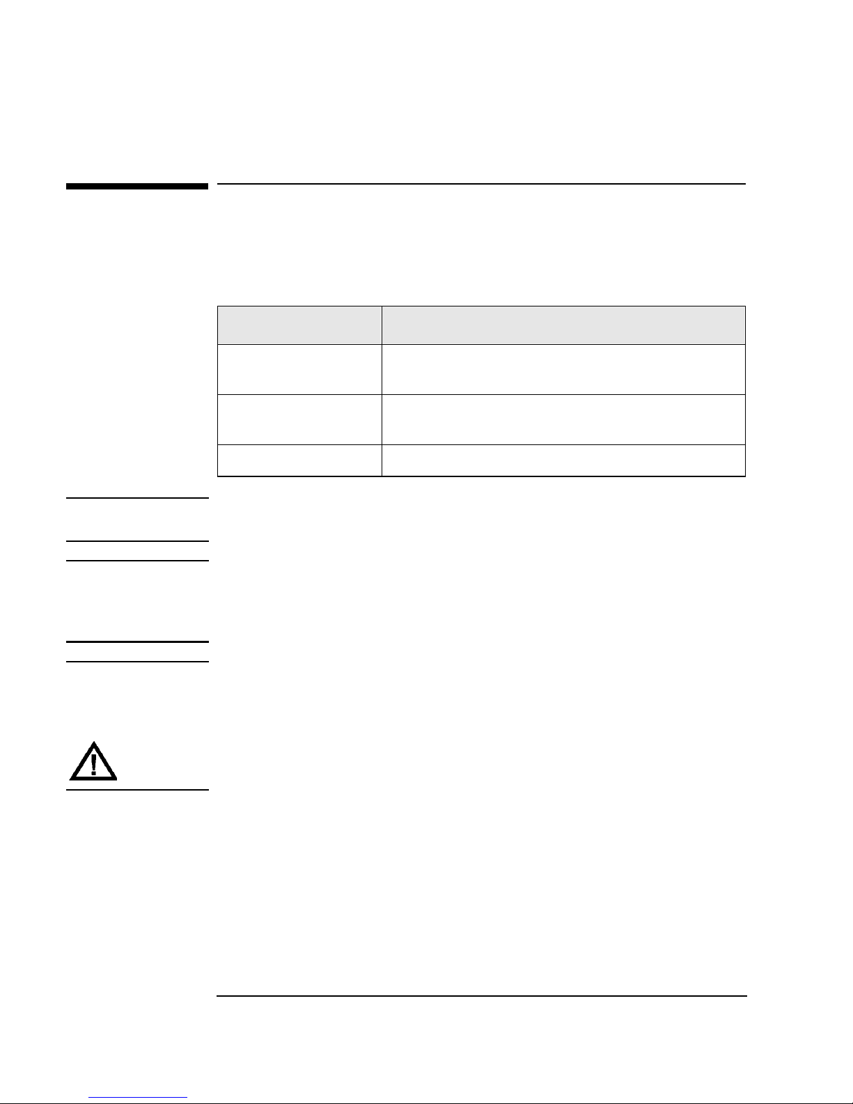
Figure 1-1 Rear Panel Features
The following list identifies the num bered components in Figure 1-1:
1 Bus 1 SCSI ports
2 SCSI interface mode switch
3 Bus 2 SCSI ports
4Power port
5 SCSI bus indicator label
6 SCSI bus st atus indicators
1-6
Page 21

Installing the T ape Library
Step 3: Install the Host SCSI Card(s)
Step 3: Install the Host SCSI Card(s)
Install the single-ended or dif ferential SCSI card into the host computer system.
Refer to the host user manual and the SCSI card ins tallation instructions for
information on installing and configuring SCSI cards.
Installation
1-7
Page 22

Installing the Tape Library
Step 4: Mount the Library in a Rack (optional)
Step 4: Mou n t the Library in a Rac k (opti onal )
For stand- alone i nstalla ti ons, g o to “Step 5: Set the SCSI Interfac e Mode Swit ch ” on
page 1-20.
The rack slides can be adjusted to fit any standard rack with a depth of 26 to 31
inches (66.04 to 78.75 centimeters).
Safety Precautions
Because th e tape library weighs approximately 100 pounds (45 kilograms), the
following safety precautions must be taken when mounting the tape libra r y:
• Fully extend the r ack’s antitip rail and lower the leveller feet.
• Mount the tape library no higher than 4 feet (122 centimeters) in therack.
• IMPORTANT: At leas t two people must lift the library during installati on.
WARNING Do not pull the library out of the rack to its fully extended position unless the
anti-tip rail on the bottom of the rack has been positioned correctly. Do not
attempt to move the tape library by yourself.
The tape library weighs approximately 100 p ou n ds (45 k ilograms). Pulling the
librar y ou t of th e ra ck w ith o u t t h e ra ck’s anti-tip ra i l ex t ended cou l d resu l t in
personal injury an d/or damage to the tape library if the rack tips over.
1-8
Page 23
Installing the T ape Library
Step 4: Mount the Library in a Rack (optional)
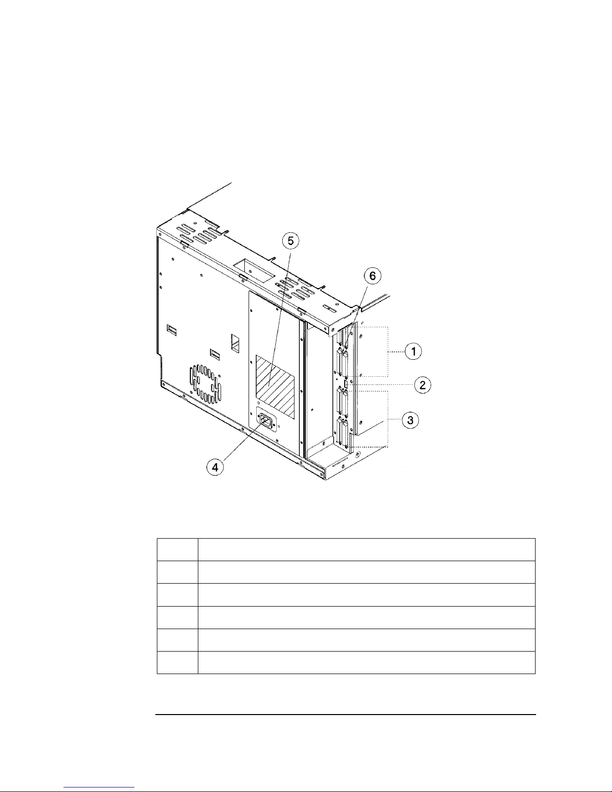
Tools and Components
Tools:
Phillips screwdriver (included in ki t)
1/2 inch open- ended wrench
Kit Hardware (parts are labeled for easy identification):
1. rack slides (1 pair)
2. bezel spacers (2)
3. mounting brackets (4)
4. strain relief bracket (1)
5. cable ties (4)
6. template
Figure 1-2 Rackmounting Compone n ts
Installation
7. 8-32 x 3/8 pan slotted phill ips lw profile
hd (14)
8. 10-32 x 5/8 pan slotted phill ips (14)
9. 10-32 clip nuts (12)
10. 8-32 keps nuts (8)
11. 6-32 x 3/8 pan phillips, with internal
lockwasher (1)
1-9
Page 24
Installing the Tape Library
Step 4: Mount the Library in a Rack (optional)
Mounting the Li brar y
To mount the tape library in a rack, you must:
• First, attach the front a nd back mounting brackets to the ra ck slides.
• Next, attach the rack slides to the rack.
• Finally, attach the tape library to the rack slides.
These steps are explained in detail in the following sections.
Attach the Mounting Brackets
1. IMPORTANT: Lower the rack’s leveller feet using a 1/2- inch open-end wrench,
and extend the rack’s antitip rail.
WARNING Failure to extend the antitip rail could result in personal injury and/or damage
to the tape library if the rack tips over.
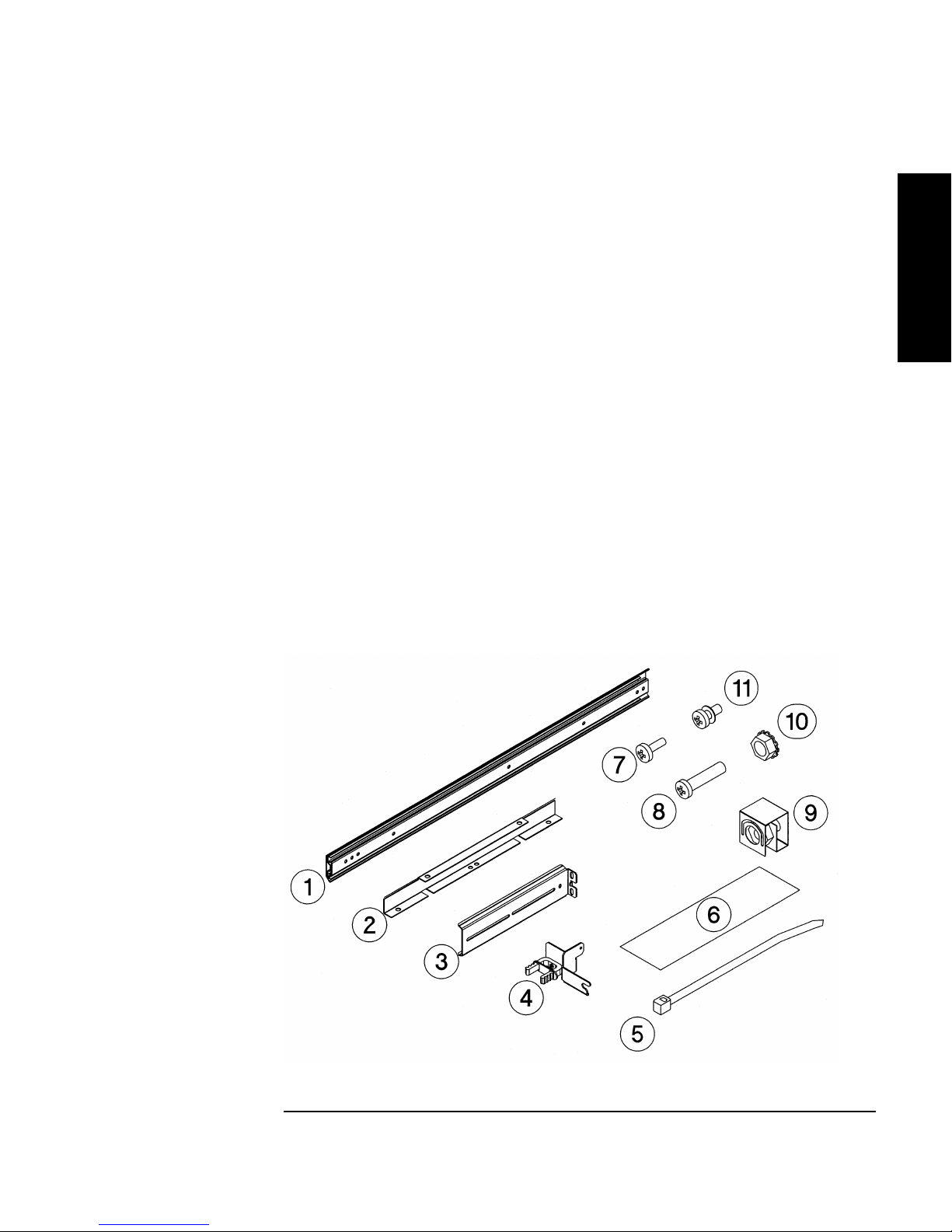
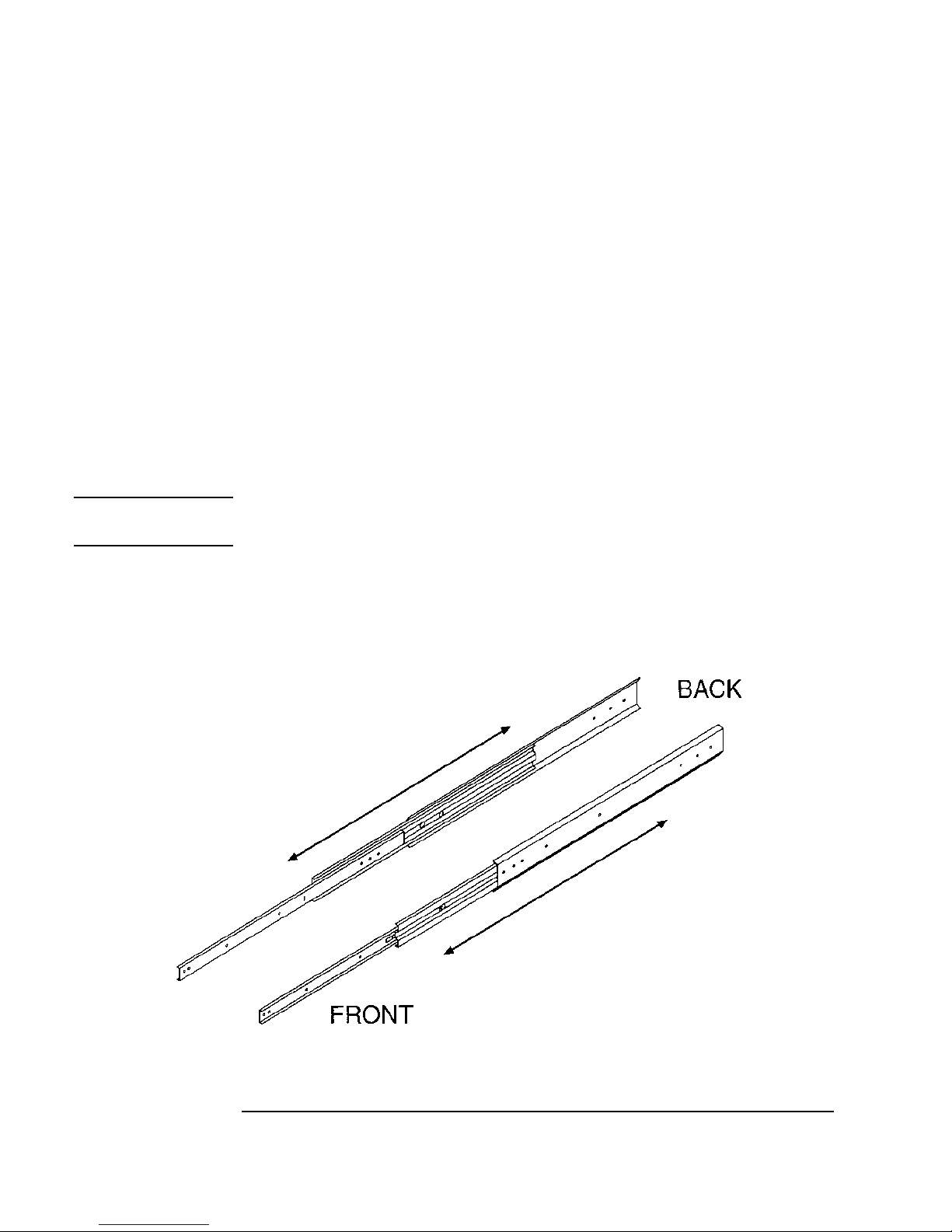
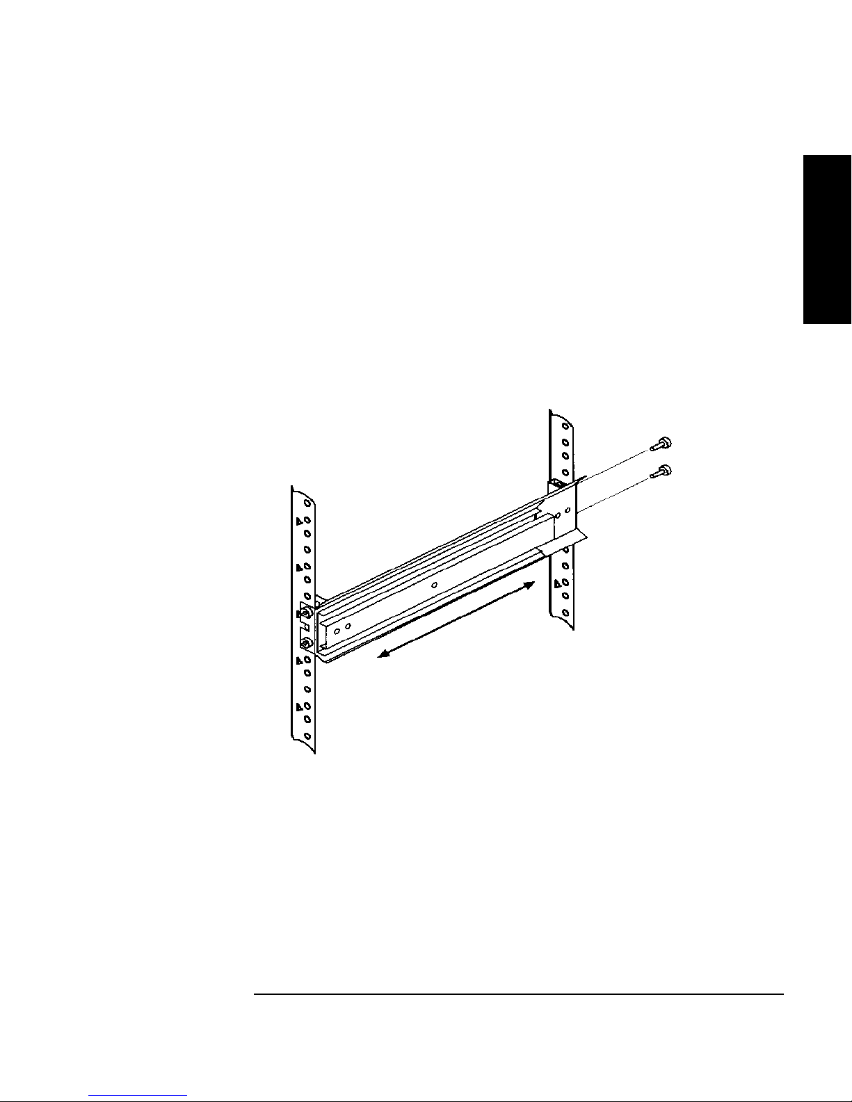
2. Pull t h e rack slide members out to the fully extended position. (The slides
should “clic k” into a locked position.)
Figure 1-3 Rack Slides
1-10
Page 25
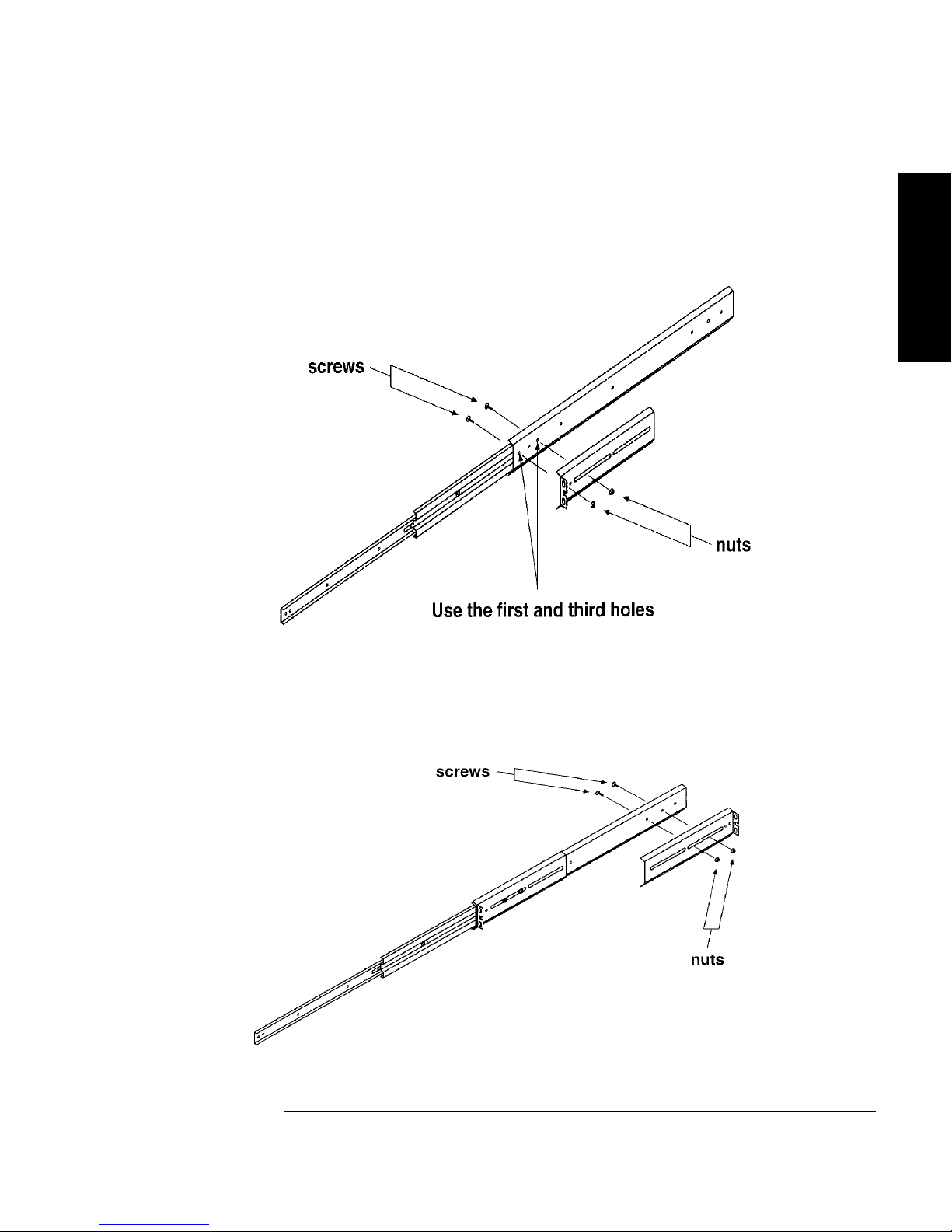
3. Attach the front mounting brackets to the front end of each slid e us ing two 8-32
x 3/8 pan-slotted phillips screws and two 8-32 keps nuts. Tighten the screws.
Figure 1-4 Front Mounting Bracket
Installing the T ape Library
Step 4: Mount the Library in a Rack (optional)
Installation
4. Attach the rea r mount ing b racket s to t he bac k side of ea ch sl ide usin g two 8- 32 x
3/8 pan-slotted phillips screws and two 8-32 keps nuts. Do not tighten the
screws.
Figure 1-5 Rear Mounting Bracket
1-11
Page 26
Installing the Tape Library
Step 4: Mount the Library in a Rack (optional)
Attach the Rack Slides to the Rack
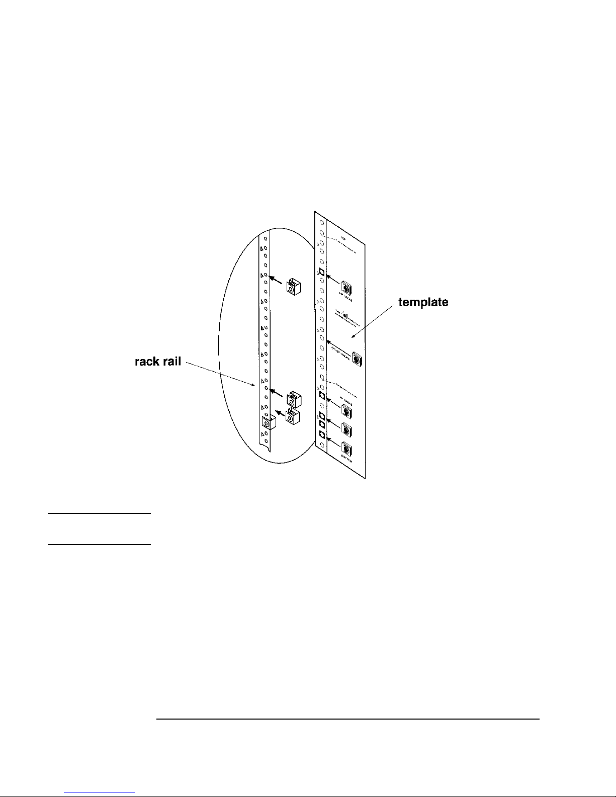
1. Line up the template with an existing product in the rack. Attach clip nuts to
each front r ail in the locations indicated on the template.
Figure 1-6 Clip Nuts (Front Rails)
NOTE Do not install the library in the bottom of the rack. Make sure the bottom of th e
library is no highe r than 4 feet off the floor.
1-12
Page 27
Installing the T ape Library
Step 4: Mount the Library in a Rack (optional)
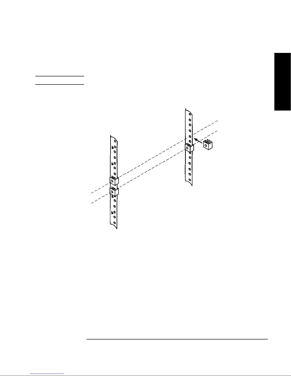
2. Attach two cl ip nut s to ea ch of th e ba ck ra ils s o tha t the s lid es will be le vel when
attache d to the rails.
NOTE Count the holes on the front and back rails to ensure the slides will be level.
Figure 1-7 Clip Nuts (Back Rails)
Installation
1-13
Page 28
Installing the Tape Library
Step 4: Mount the Library in a Rack (optional)
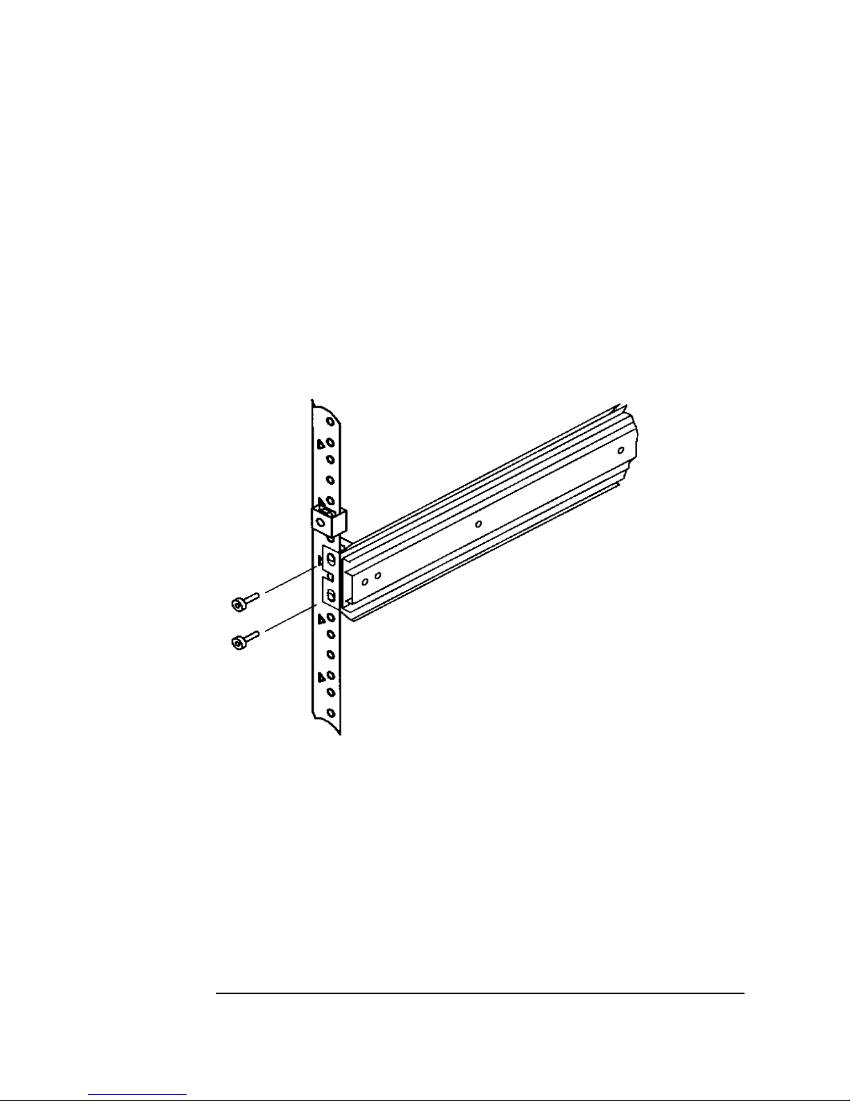
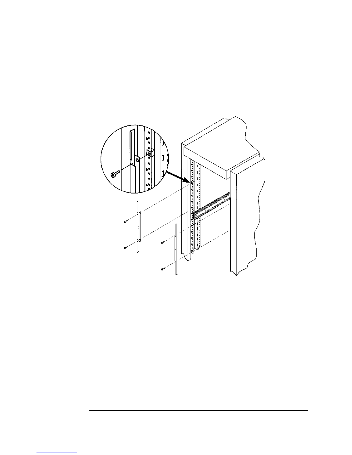
3. Attach the front bracket:
a. Return the slides to their compressed position.
b. Attach the front sli de mounting bracket to the lower two clip nuts on the
front rails using two 10-32 x 5/8 pan slotted phlp screws .
c. P u sh th e s li d es as far as po ssible to w ar d th e o u tsi d e of th e rack.
d. Tighten the sc rews.
Figure 1-8 Front Bracket on Rack
1-14
Page 29
4. Attach the rear bracket:
a. Adjust the rear mounting brackets to fit lengthwise in the rack.
b. Attach the rear sli de moun tin g bracket to the rea r cli p nuts using two 10-32 x
5/8 pan slotte d phlp screws.
c. P u sh th e s li d es as far as po ssible to w a rd th e o u tsi d e of th e rack.
d. Tighten the sc rews.
e. Tighten all bracket screws.
Figure 1-9 Rear Bracket on Rack
Installing the T ape Library
Step 4: Mount the Library in a Rack (optional)
Installation
5. Extend the slides fully, make sure they are parallel, and then recompress them.
1-15
Page 30
Installing the Tape Library
Step 4: Mount the Library in a Rack (optional)
6. Connect the two bezel spacers to the fron t rails usi ng two 10-32 x 5/8 p an slo tte d
phlp screws. The screws attach to the two clip nuts on the front rails above the
slides.
Figure 1-10 Bezel Spacers
1-16
Page 31
Installing the T ape Library
Step 4: Mount the Library in a Rack (optional)
Place the Library in the Rack
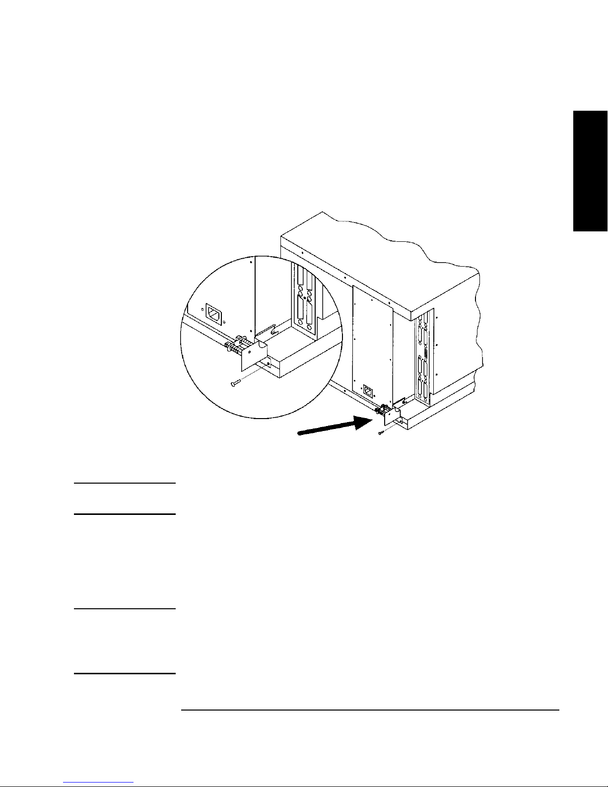
1. Attach the cable strain relief bracket to the library rear panel below the SCSI
connectors using one 6-32 x 3/8 pan phlp, with internal lockwasher screw.
Figure 1 - 11 Strai n Re lief Bra ck e t
Installation
2. Ensure that the rack’s anti-tip ra ils are extended.
WARNING Failure to extend the rack’s anti-tip rail could result in personal injury and/or
damage to the tape library.
3. Remove the keys from the library handle.
4. Important – two people needed: Lift the library onto the slides and back slightly
into the rack using the side handles. Make sure the handles sit securely on the
slides and that the front hol es in t he li brary li ne up with the secon d hole from the
fro n t on th e slid e s .
WARNING Do not attempt to move the tape library by yourself.
The tape library weighs approximately 100 p ou n ds (45 k ilograms). To avoid
personal injury and/ or damage to the tape library, a minimum of two people
are need ed to mo v e the librar y.
1-17
Page 32

Installing the Tape Library
Step 4: Mount the Library in a Rack (optional)
5. Attach the libra r y to ea ch s lide using three 8-32 x 3/8 pan-slotted phillips
screws.
Figure 1-12 Library on Slides
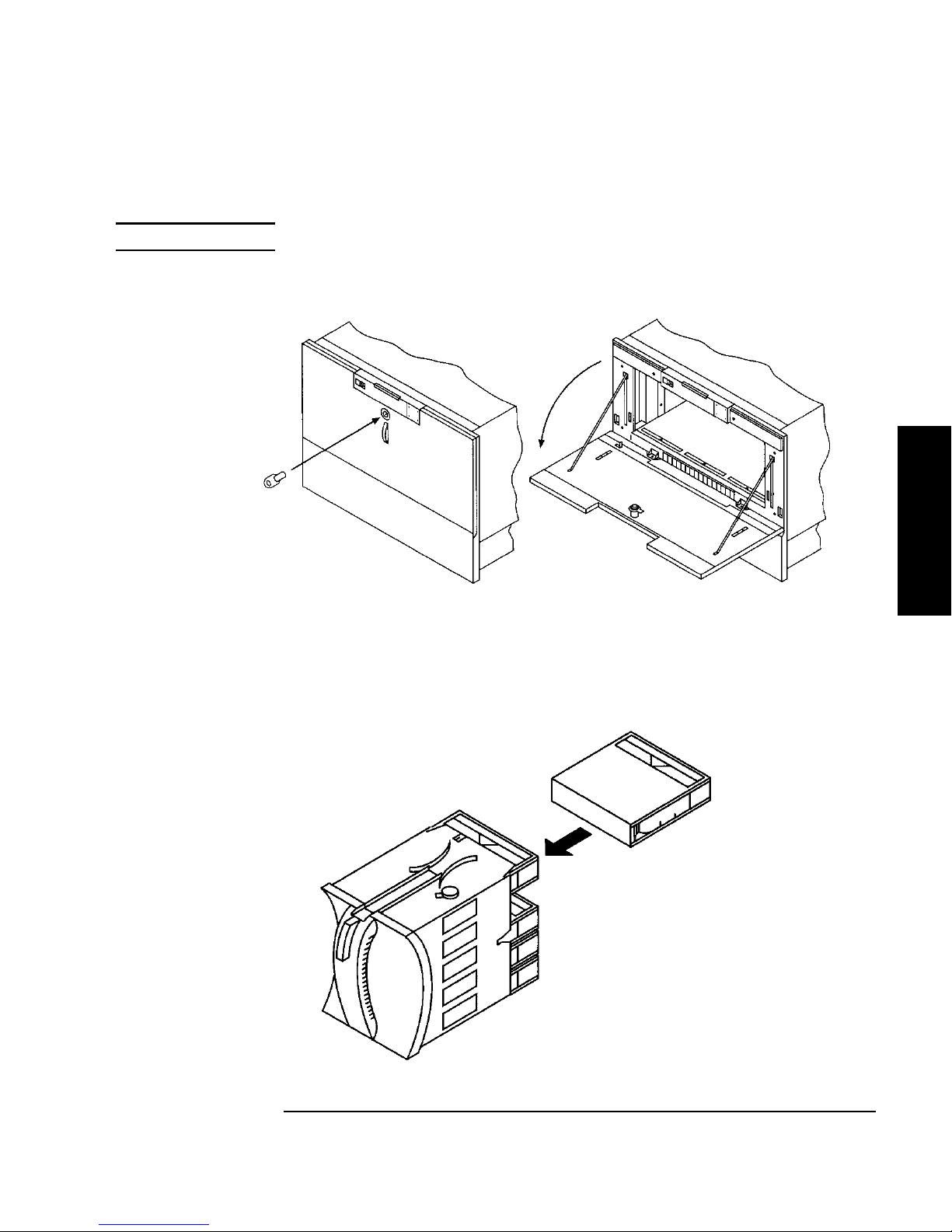
6. Remove the installation handle s by re moving two screws on each handle . Kee p
the screws and handles in ca se the library needs to be reshipped in the future.
Figure 1-13 Installation Handles
1-18
Page 33

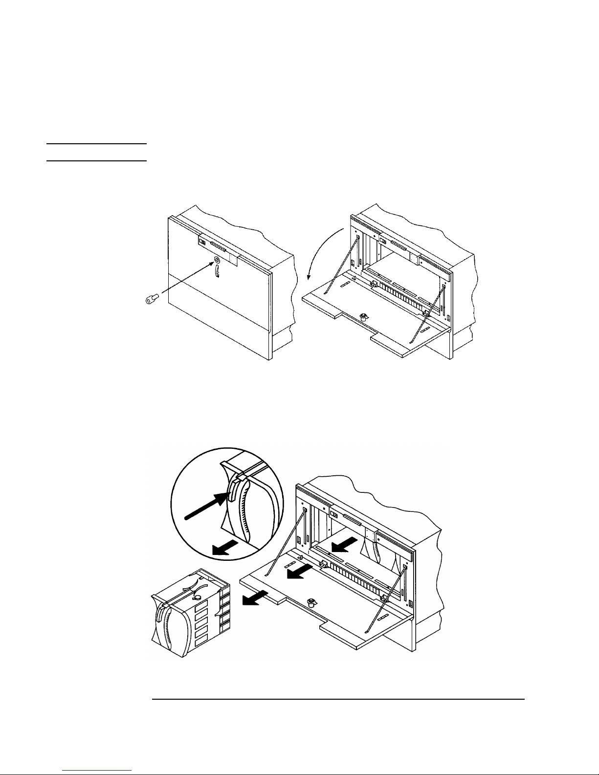
7. Release the slide latch springs, then push the tape library into the rack.
8. Open the front access door using the key, and secure the library to the rack
through the recta ngular holes in the door us ing two 10-32 x 5/8 pan slot ted phlp
screws.
Figure 1-14 Front Access Door
Installing the T ape Library
Step 4: Mount the Library in a Rack (optional)
Installation
1-19
Page 34

Installing the Tape Library
Step 5: Set the SCSI Interface Mode Switch
Step 5: Set the SCSI Interface Mode Switch
Do not connect any cables yet.
The SCSI interface mode switch, shown below, is on the rear panel between the bus
1 and bus 2 SCSI ports.
Figure 1-15 S CS I Interface Mode Switch (Example)
To set the SCSI interface mode switch:
1. Determine how to connec t the library according to:
• Number of drives in the library and drive type
• Other peripherals (if any) on your system
• Type of SCSI card (differential or single-ended)
NOTE For best library performance, connect only one library on a SCSI bus.
2. Set the SC S I in terfa c e mo de swit ch.
Table 1-4 SCSI Interface Mode Switch Settings
Setting Purpose Set to
Term Pwr Sends power to the te rmi nator. ON in most installations
T er min ation T erm inate s the SCSI bus . Fun ctions t he
same as a physical terminator.
ON if the tape drive is the last devic e
on the SCSI chain
OFF if anothe r periphera l will conn ect
to the lib r ar y
DIFF/SE Specifie s whether you are using the
differential or single-ended port.
DIFF for differential
SE for single-ended
1-20
Page 35
Installing the T ape Library
Differential SCSI
Step 5: Set the SCSI Interface Mode Switch
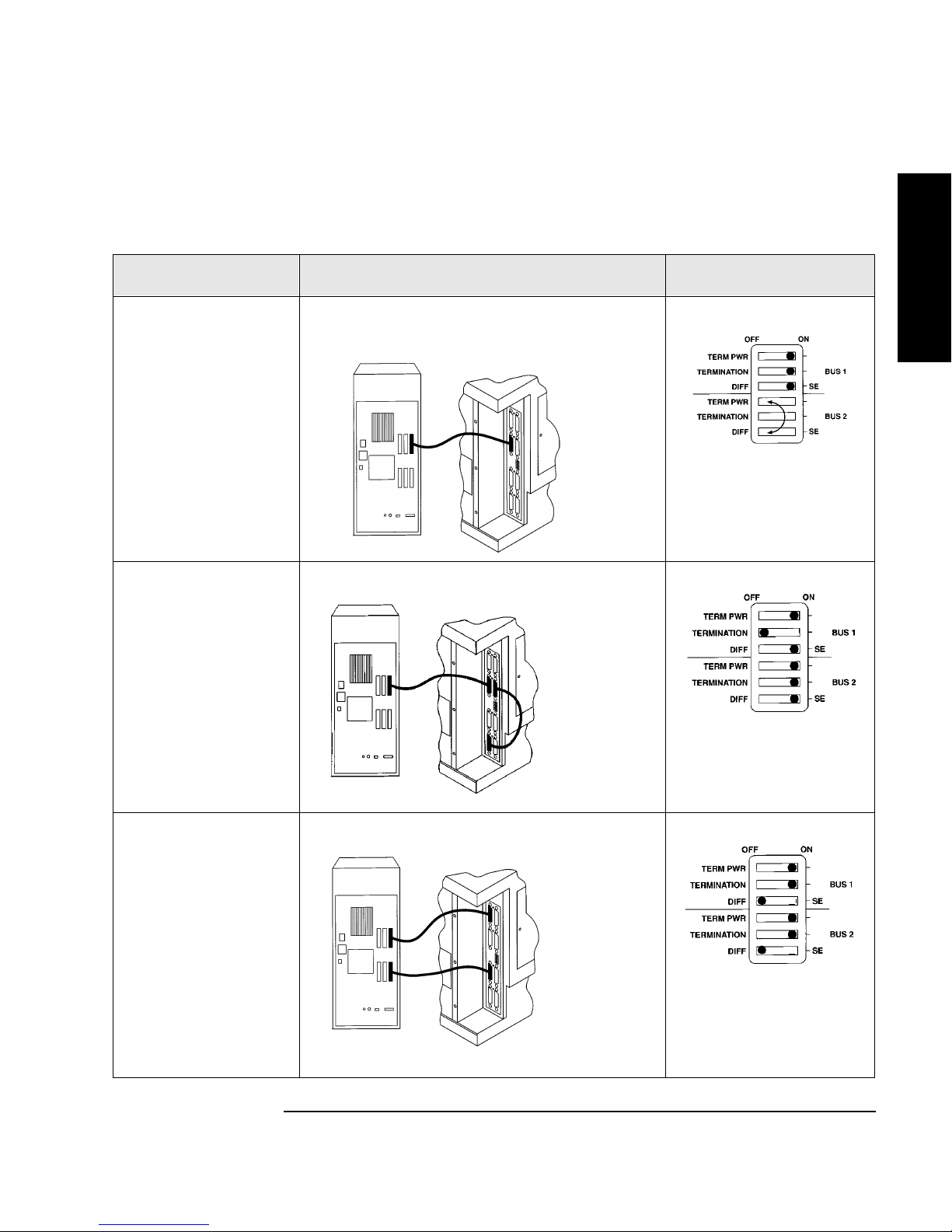
The following ta ble shows connection options when there are no other peripherals.
Table 1-5 Tape Library as the Only Peripheral
Configuration Cabling Mode Switch Settings
One-Drive Tape
Library
Single-ended SCSI
connection
Installation
Two-Drive Library:
Daisy chained
Minimum host I/O
slots used
Two-Drive Library
Bus 1 and bus 2
connect to s eparate
SCSI cards
Maximum
performance
Additiona l ca rd and
cable req u ired
Single-ended
SCS I conn e ctio n
shown
connection shown
1-21
Page 36

Installing the Tape Library
Single-ended SCSI
Single-ended
Step 5: Set the SCSI Interface Mode Switch
The following ta ble shows connection options when there are other peripherals.
Table 1-6 Tape Library with Other Peripherals
Configuration Cabling Mode Switch Settings
One-Drive Tape Library:
Library on its own bus
connection shown
Maxi mum performance
One-Drive Tape Library:
Daisy chained to
peripheral
connection shown
SCSI
bus 2 not use d
Minimum host I/O slots
used
Two-Drive Library:
Daisy chai ned lib rary and
peripheral
Minimum host I/O slots
used
Two-Drive Librar y: bus 1
and bus 2 use separ ate
SCSI cards
Additiona l card and c able
required
Minimum I/O slots used
EXVQRWXVHG
1-22
Page 37

Installing the T ape Library
Step 6: Connect Library to Host
Step 6: Connect Library to Host
Do not turn on the host system or library yet!
1. Properly shut down all peripheral devices connected to the host computer.
If the host computer is connect ed to a network, be sure to check with the system
administrator before switching off power.
2. Switch off power to the server .
3. Connect the SCSI ca bles.
Before you set the mode switch, you determined how to configure your SCSI
bus (see the connection diagrams on page 1-21 and page 1-22). Using this
configuration, connect the library to the host. Make sure:
• You use the proper port (single-ended or differential).
Installation
• The last device in the SC SI bus is terminated.
4. Make sure the power switch on the library front panel is s witched off.
5. Plug the power cord into the power port on the back of the library.
Stand-alone installations: Go to “Step 7: Power On the System” on page 1-27.
Rack mount installations: Go to th e next section, “Routi ng SC S I and Power Cables
on Rack Mounted Libraries.”
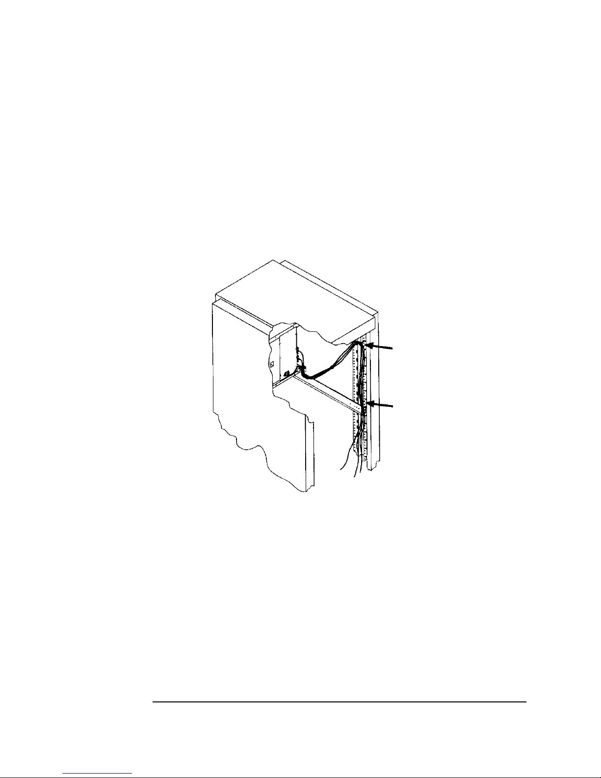
Routing SCSI and Power Cables on Rack Mounted
Libraries
CAUTION SCSI and power cables must be routed and secured properly on rack mounted
libraries. Failure to properly route library cables could result in damage to the
cables.
To properly route and secure rack mounted library power and SCS I ca bles:
1. Route the SCSI/powe r ca bles through the strain relief bracket:
a. Squeeze the two plastic ends of the cable str ain relief bracket together.
b. Pull off the plas tic strain relief clamp.
1-23
Page 38

Installing the Tape Library
Step 6: Connect Library to Host
c. Route the SCSI cable ( s) and the power cord through the cable strain relief
bracket.
d. Slide the str ain relief clamp back onto the bracket.
e. Attach a ca ble tie (included in the rack mount kit) to the SCSI and power
cables about eig h t inches back from the strain reli ef bracket.
f. Attach another cable tie about eight inches back from the first cable tie.
Figure 1-16 SCSI/Power Cabl es and Strain Relief Bracket
2. Extend the rack’s anti- t ip ra il and ver i f y th at the lev el ler feet a re do w n .
WARNING Failure to extend the antitip rail could result in personal injury and/or damage
to the library if the rack tips over.
1-24
Page 39

3. Use the key to open the front access door. Remove the two screws that secure
the library to the rack.
Figure 1-17 Front Access Door
Installing the T ape Library
Step 6: Connect Library to Host
Installation
4. Slide the library out of the rack so that it is in the fully extend ed position.
1-25
Page 40
Installing the Tape Library
Step 6: Connect Library to Host
5. Gently pull the SCSI a nd power cables back toward the rear of the rack. Use a
cable tie to sec ure the m to the rail at t he back of the rack. T he cable ti e shoul d be
at about the same height as the top of the library.
6. Carefully route the cables down along the back rail. Use a cable tie to secure
them to the rail just above the slide mounting bracket. Clip off the ends of all
four cable ties.
Figure 1-18 Secured SCSI and Power Cables
7. Close the back door on the rack.
8. Push the library bac k into the rack.
9. Open the front ac cess door. Replace the two screws that secure t he library to the
rack, then re-lock the door.
1-26
Page 41

Installing the T ape Library
Step 7: Power On the System
Step 7: Power On the System
1. Plug the power cord into a grounded outlet.
2. Turn on the power sw itch.
Initially SELF TEST and NOT READY, and then NOT READY and INVENTORY
CHECK alternately appear in the display window on the library . After the
power-on test completes (approximately 1.5 minutes), the drive status
information displays. (See “Understanding Display Window Mes sages” on
page 3-4.)
NOTE If the drive status inform ation doe s not dis play, the power-on test wa s not succ essful
and DEVICE FAILED displays. See “Troubleshooting ” on page 3-38 for
troubleshooting procedures.
3. Turn on other peripherals (if any).
Installation
4. Turn on the host system.
Inst a l l Back up Software
Follow the instru ctions provided with your backup soft ware to configure it to your
library. Several trial versions are provided with the library for your eva luation.
Verify Installation With TapeAssure
HP TapeAssure is a software utility that tells you quickly and easily whether your
configuration is correct and whether the ta pe drive is ready for use with backup
software. Your backup software must be TapeAlert compat ible for you to receive
these messages (compatible packages will display the HP Ta peAlert logo). For the
latest lis t of bac kup pac kages that support TapeAlert, refer to HP’s World W ide
Web site (http://www. hp.com/go/tape).
1-27
Page 42

Installing the Tape Library
Moving or Shipping the Library
Moving or Shipping the Library
This section explains how to move the li brary a short distance, such as to another
office or to another floor in the building and how to s hip the library to another
location.
WARNING The library weighs approximately 100 pounds (45 k ilograms). To avoid
personal injury and possible damage to the library, at least two people must
move the library.
To move or ship the library:
1. Properly shut down and power off the host.
2. Unmount (unreserve) an y tape cartridges in the library if nec essary. See your
computer operating system documentation, or software application
documentation for instructions on how to unmoun t tape cartridges.
3. Verify that al l d ri v es in th e librar y ar e empty:
If the drives are full, empty them before shipping the library. (For instructions,
refer to the software documentation your host syste m uses to manage the
library.)
4. Switch off the power switch on the library front panel.
CAUTION Do not switch off power to the library until the SCSI bus is inactive.
Removing power from a SCSI peripheral when the bus is active ca n r esult in data
loss and/or indeterminate bus states. (Check your host system manuals for
information about checking the SCSI bus status.) If your computer is connected to a
LAN, be sure to check with your system administrator before shutting off power to
the library.
5. Remove the power cord and the SCSI cable connections from the library rear
panel.
1-28
Page 43

Installing the T ape Library
Moving or Shipping the Library
6. If the library is rack mou nted:
a. Extend the anti-tip rail on the r ack.
WARNING Failure to extend the anti-tip rail could result in personal injury and/or damage
to the library if the rack tips over.
b. Slide the library out of the rack so that it is in the fully extended position.
c. Reattach the handles to the side of library using two screws. Make sure the
handle flanges are on top of the slides. (The handles and hardware for
reattachi ng them should have been saved with the original shipping
materials. If they are missing, call your service representative to order
replacement handles.)
d. Remove the three 8-32 screws on ea ch s ide of the library that secure the
library to the rack slides.
e. IMPORTANT — two people needed: With a person on each side of the
librar y, lift the library onto a cart.
Installation
7. Transport the library:
• To move the libra r y a short distance, roll the cart to the new location.
• T o ship the library, repackage the library in the same materials and ship it in
the same manner in which it was rece ived.
CAUTION The library ca n be s eriously damaged if it is not s hipped using appropriate shipping
materials. A service representati ve ca n provide assistance or advic e on how to best
repackage and ship the library .
8. Re-install the libra r y. Refer to installation steps in this chapter.
1-29
Page 44

Installing the Tape Library
Moving or Shipping the Library
1-30
Page 45

Using Tapes
2 Using Tape Cartridges
2-1
Page 46

Using Tape Cartridges
Tape Cartridge Overview
Tape C artridg e Over view
The tape cartridges you use in the tape drive are an in tegral part of the storage
process. Thi s c hapter explains how to:
• Choose a tape cartridge.
• Label tape cartridges with bar code labels.
• Label bulk load magazines.
• Interpret drive cleaning messages.
• Write-protect a tape cart ridge.
• Maintain a tape cartridge.
NOTE For top performance an d r eliability , H ew lett Pack ard recommends HP-labeled tape
cartridges that have been fully tested for use with HP’s tape pr oducts. Purchase
these cartridges through any HP-authorized dealer, or order them through HP
Direct. See “Supplies and Accessories” on page A-3 for ordering information.
2-2
Page 47

Using Tape Cartridges
Choosing Tape Cartridges
Choosing Tape Cartridges
Two types of compatible digital linear tape cartridges are available:
Table 2-1 Supported Tape Types
Cartridge Type Availabl e Densities
HP DLTtape IV Data Cartridge 20 GBytes uncompressed
(DLT4000 drive)
35 GBytes uncompressed
(DLT7000 drive)
HP DLTtape III XT Data Cartridge 15 GBytes uncompressed
NOTE Hewlett- Packard recommends using the HP DLTtape IV Data Cartridge for top
performance, highest capacity, and least amount of head cleaning.
Using Tapes
Using Tape Cartridges
2-3
Page 48

Using Tape Cartridges
Labeling Tape Cartridges
Labeling Tape Cartridges
Make it a pra ctice to use bar code labels on your tape cartridges. Your host software
may need to keep track of the following information and the associated bar code:
• date of format or initialization
• cartridge owner (such as group or department)
• storage purpose (such as backup, old version of operating system)
If the host s of tware does not kee p tr ack of t his i nformation , c reate a method of doi ng
so.
Slide the lab el into th e slot on th e face o f th e c ar t ri d g e as illust r ated in F ig ure 2-1 .
NOTE If bar code labels are not used and the “Barcode On/Off ” configuration is set to
“Off,” the Inve ntory Che ck test per form ance can be si gnifica ntly i mpact ed. T his te st
runs when the library is powered on and whenever the front acc es s door is opened.
See Appendix A for infor mation about ordering addit ional bar code labels.
Figure 2-1 Proper Label Position
2-4
Page 49
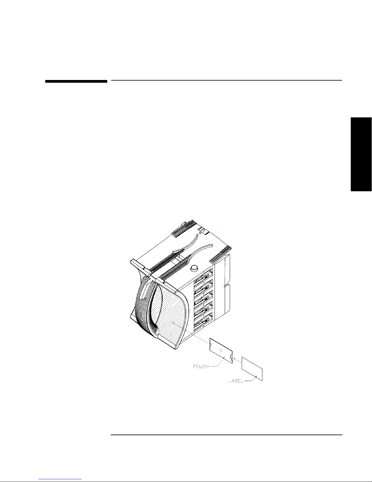
Labeling Bu lk Load Magazi nes
Bulk load magazines can be labeled in a manner sim ilar to tape cart r idges.
To label bulk load magazines:
1. Clean the magazine s urface with isopropyl alco hol (optional, but
recommended).
2. Remove the adhesive ba cking from the label pouch.
3. Apply the pouch to the magaz ine anywhere within the shaded ar ea shown in
Figure 2-2.
4. Slide the label into the pouch.
Figure 2-2 Magazine Label Position
Using Tape Cartridges
Labeling Bulk Load Magazines
Using Tapes
Using Tape Cartridges
2-5
Page 50

Using Tape Cartridges
Drive Cleaning Messages
Drive Cleaning Messages
Table 2-2 lists drive cleaning messages that might be caused by a tape. Note that:
• The tape drives do not req uire s chedu led cleani ng mai ntena nce. Exce ssive use o f
the cleaning cartridge can cause unnecessary wear on the drive head.
• After 20 cleaning cycles, the cleaning cartridge must be replaced.
NOTE For drive cleaning ins tructions, refer to “Cleaning the Library T ape Drives” on
page 3-23.
2-6
Page 51

Table 2-2 Drive Cleaning Messages
If this happens: Reason: You need to:
Using Tape Cartridges
Drive C leanin g Me ss ages
A brand new tape
cartridge is used
and a drive
cleaning message
is received.
An older,
frequently used
tape cartridge is
load ed an d a dr iv e
cleaning message
is received.
An older,
frequently used
tape ca us es a
cleaning message
to be displa yed for
the second ti me .
Debris from the
tape manufacturi ng
process was
deposited on the
drive head.
Dust from frequent
tape loads and
unloads has
probably built up
on the tape
cartridge and was
deposited on the
drive head.
The tape is
probably damag ed.
(Damag ed
cartridges can
cause unnecessary
use of the cleaning
cartridge.)
Clean the drive using the tape library cleaning procedure in
“Cleaning the Librar y Tape Drives” on page 3-23.
If the message is displayed again within a short amount of
time, replac e th e cart rid g e.
Clean the outside of the tape cartridge with a damp cloth.
Clean the tape drive using the tape drive cleaning procedure
in “Cleaning the Library Tape Drives” on page 3-23.
1. Ve rify the tape is readable by clearing the error message.
(Select the ONLINE REPAIR option from the control
panel. Turn off the drive containing the tape. Turn the
drive on again. (See “Using Online Drive Replacement”
on page 3-36).
2. Try reading the tape again:
• If the tape can be read, back up data from the
damaged cartridge to another tape cartridge and
discard the damaged one.
Using Tapes
Using Tape Cartridges
• If the tape cannot be read, call service.
2-7
Page 52
Using Tape Cartridges
Write-Protecting Tape Cartridges
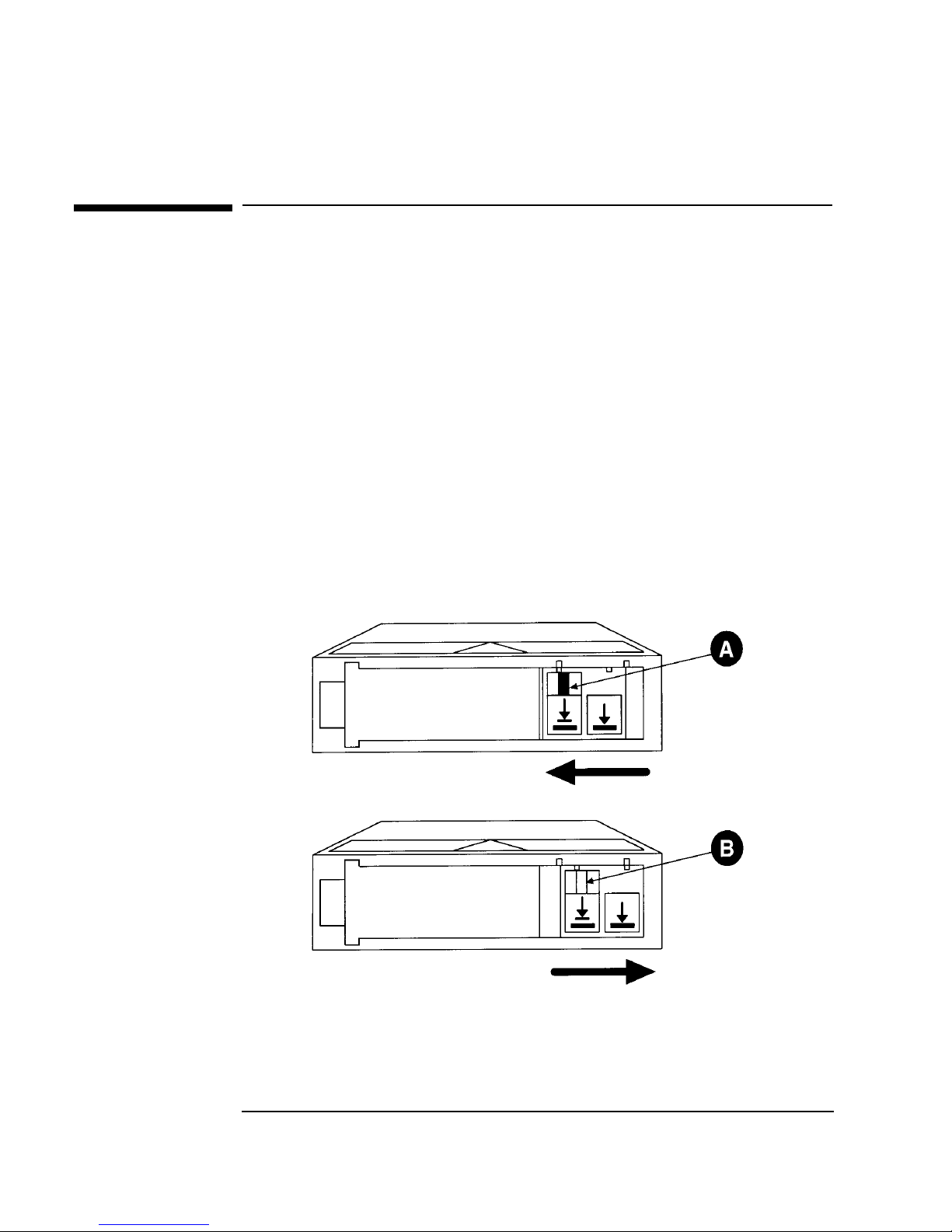
Write-Pro tecting Tape Ca r t ridges
The use of the write protec t swi tch ensures data safety for files tha t have bee n
previously wri tte n to the ta pe and preven ts any a ddition al file s from being wri tte n to
the tape.
To change the write-protect setting, move the write-protect switch:
•Left to prevent data from being written to the cartri dge. T he orange indica tor on
the cartridge can be seen when the write-protect switch is in the “ON” position
(see “A” in Figure 2-3).
• Right to allow data to be writt en to the cartridge. The orange i ndicator on the
cartridge cannot be seen when the write-protect switch is in the “OFF” position
(see “B ” in F igu r e 2 - 3).
With the write-protect switch in either position, data can be read from the cartridge.
Figure 2-3 Write-Protect Button Settings
Not Write-Protected
Write-Protected
2-8
Page 53

Maintaining Tape Cartridges
Table 2-3 Tape Cartridge Maintenance
Using Tape Cartridges
Maintaining Tape Cartridges
DO NOT: DO:
• Expose cartridges to magnetic fields.
• Leave cartridges in the tape drive
when library power is off.
• Expose cartridges to extreme
tempe r at u r es o r ex t r eme humid it y.
Acceptable operating temperatures
range from 10-40° C (50-104° F).
Acceptable storage temperatures
range from 16-32° C (60-90° F).
Acceptable operating humidity
ranges from 20-80%; acceptable
storage humidity ranges from
10-95%.
• Expose cartridges to moisture or
direct sunlight.
• Drop the cartridges or car ry t hem in a
loose container that could submit the
cartridges to any unnecessary
physical shock.
• Store cartridges in a clean, safe
place in their protective plastic
containers when not in us e.
• Remove dust on the outside of
cartridges us ing a damp cloth.
(Older, frequently used tapes
may build up dust.)
• Store cartridges vertically, not
flat.
• Store car tr idges intended for
archiving data in their plastic
containers and in environmental
conditions of 18-28° C (64-82°
F) and 40-60% relative
humidity.
• Use labels like th os e includ ed i n
the accessories kit or that meet
the specifications listed in Table
A-1 on page A-3.
Using Tapes
Using Tape Cartridges
• Open cartridges lid, exposing the
• Touch the tape s u rface.
• Take cartr i d ge s ap ar t .
• Use graphite pencils, water s oluble
• Erase a label; replace it instead.
tape to possible contamination or
physical damag e.
felt pens, or other debr is-producing
writing instruments to label
cartridges.
2-9
Page 54

Using Tape Cartridges
Maintaining Tape Cartridges
2-10
Page 55

Library Operation
3 Operating the Library
3-1
Page 56

Operating the Library
Overview
Overview
This chapter exp lains the following library operations:
• “Operating the Control Panel” on page 3-3
• “Understanding Display Window Messages” on page 3-4
• “Entering the Administration Menu Password” on page 3-9
• “Setting a New Administration Menu Password” on page 3-10
• “Setting and Viewing SCSI IDs” on page 3-11
• “Loading Tape Cartridges Into theLibrary” on page 3-15
• “Removing Ta pe Cartridges from the Library” on page 3-19
• “Viewing Cartridge Bar Code Labels” on page 3-22
• “Cleaning the Library Tape Drives” on page 3-23
• “Using Online Drive Replacement” on page 3-36
• “Setting Configuration Options” on page 3-25
• “Retrieving Perform anc e Information” on page 3-28
• “Running an Internal Test” on page 3-32
• “Using Online Drive Replacement” on page 3-36
• “Troubleshooting” on page 3-38
3-2
Page 57

Operating the Control Panel
Figure 3-1 Tape Library Control Panel
Operating the Library
Operating the Control Panel
Library Operation
1. Selection buttons allows you to perform the following operations:
CANCEL cancels the current operation or option.
•
PREV scrolls the display options backward by one. When held continuously,
•
the options scroll quickly.
NEXT scrolls the display options forward by one. When held cont inuously,
•
the options scroll quickly.
ENTER selects the displayed option.
•
2. Activity li ght indicates the following:
• Steady Green – power is on.
• Flashing Green – a tape cartridge is being accessed.
• Amber – fault indicator.
3. 16-Character Display displays information about the current operation or drive
status. An asterisk (*) indi cates there is a menu beneath th e option. Press
to access the menu. Press
NEXT or PREV to display the menu options.
ENTER
4. Power switch switches power to the unit on and off.
5. Door latch locks/unlocks door for access to bulk load magazines.
3-3
Page 58
Operating the Library
Understanding Display Window Messages
Understanding Display Window Messages
The display window dis plays drive status indicators and menu options.
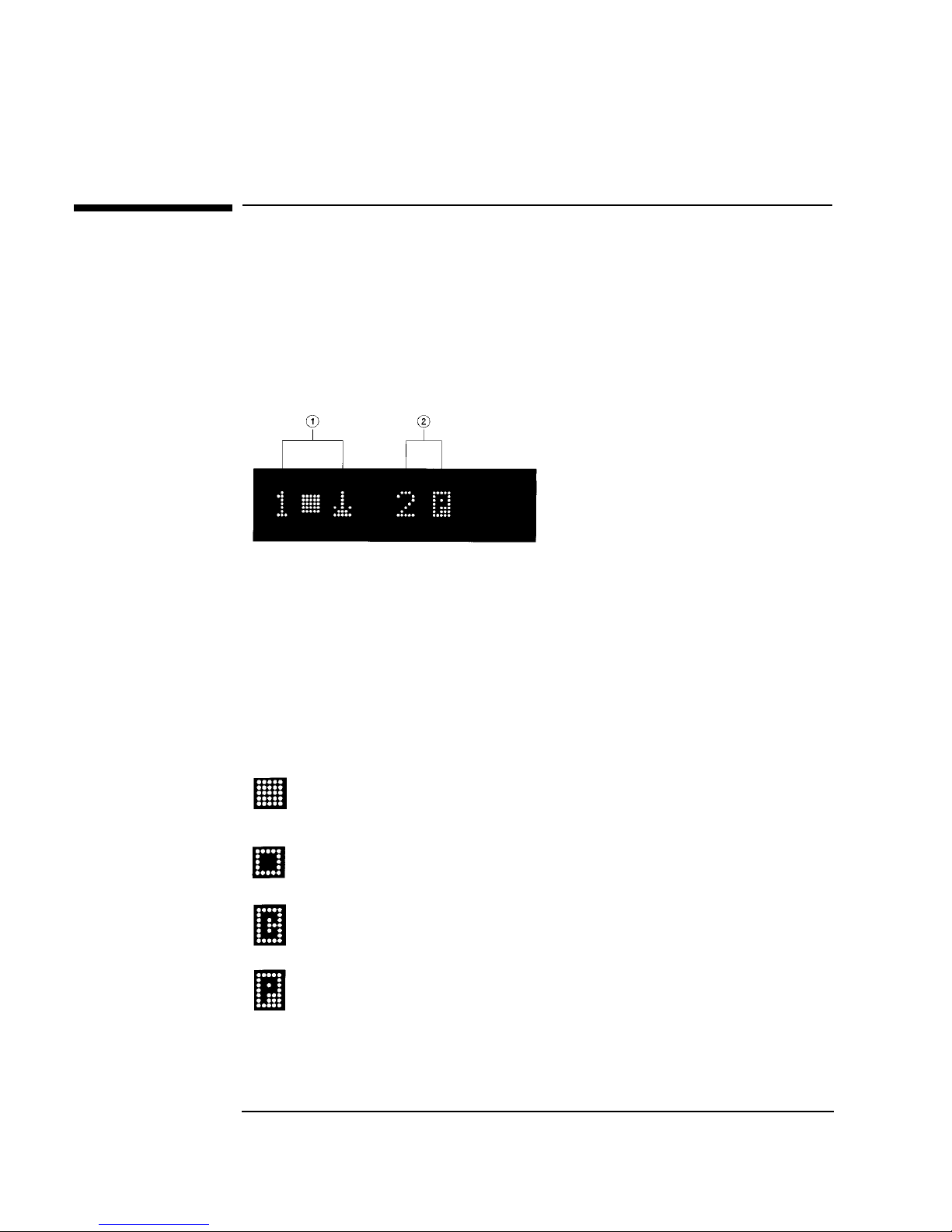
Drive Status
The following figure shows the drive status indicators displaye d wh en the library is
in the “ready” s t at e.
In this example:
1. Drive 1 has a cartridge inserted and data is being written to the tape.
2. Drive 2 has a write-protected cartridge inserted.
S tatus Indicators
Status in dicat ors provi de drive status informatio n for the drive numbe r tha t precede s
one of the following indicators.
The drive is full.
The drive is empty.
The drive needs to be cleaned.
The tape cartridge in the drive is write -protecte d .
3-4
Page 59

Understanding Display Window Messages
Activity Indicators
The activity light flashes duri ng the following operations:
Information is being writte n to the tape in the drive.
Infor mation is be in g r ead to the tap e in the drive.
The tape in the drive is being searched backward or is rewinding.
The tape in the drive is being seached forward.
The driv e is b ei n g cl ea n ed .
Operating the Library
Library Operation
3-5
Page 60

Operating the Library
Understanding Display Window Messages
Control Panel Options
Press PREV or NEXT while the librar y is in the “ready” state to display fir st-level
options. Access second-level options from ADMIN * (second level options require a
password; see “Entering the Administration Menu Password” on page 3-9).
An asterisk (*) indicates that the option has multiple selections.
When a menu selection is flashing, press
option’s selections. Press
PREV or NEXT to display other available options.
ENTER to select the option or display the
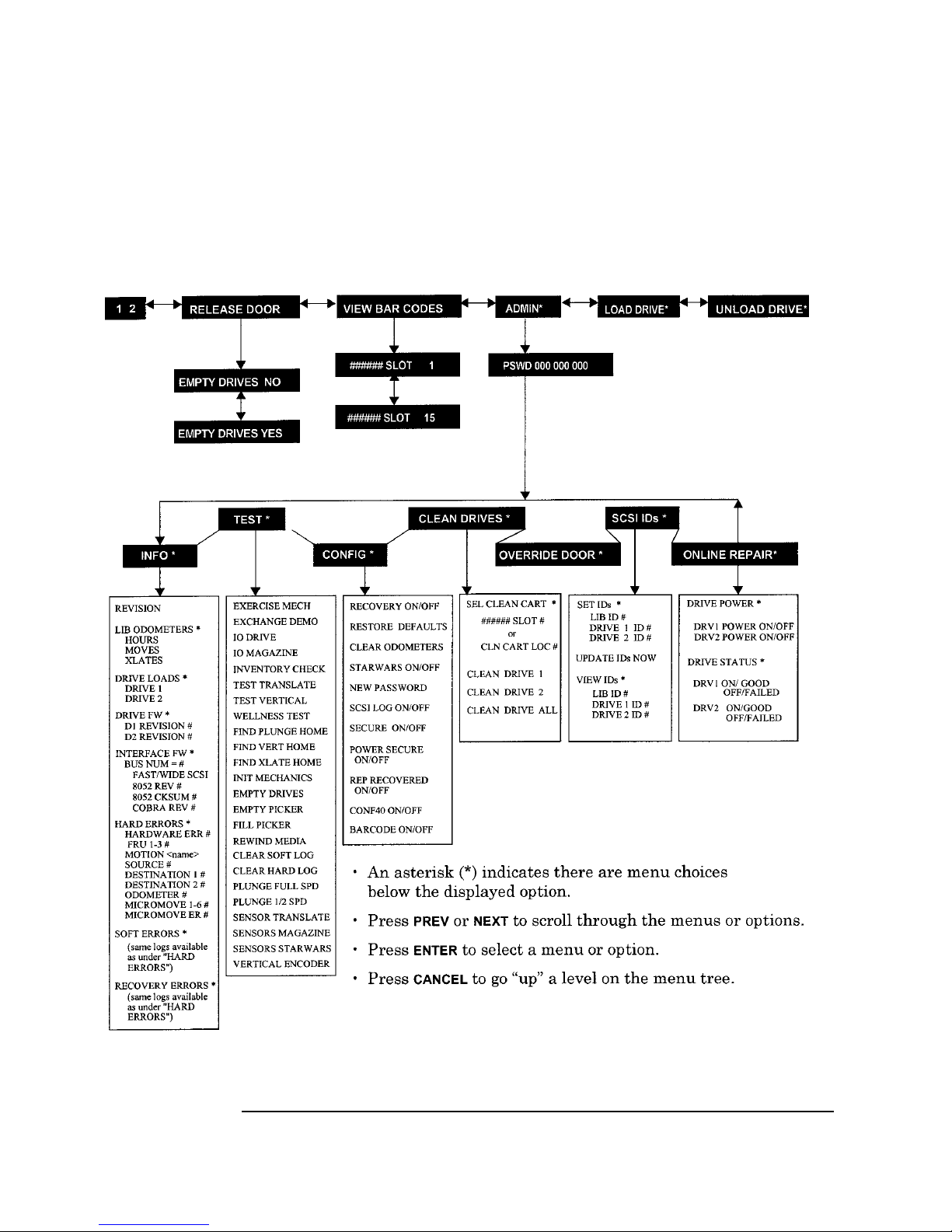
First Level Options
RELEASE DOOR Select to allow the access door to be unlocked.
VIEW BAR
CODES *
ADMIN * Accesses se cond-level options.
LOAD DRIVE * Loa d s a tape from a slot to the drive. To load a tape:
Select to view the bar code labels on each tape cartridge
by slot number.
1. Select the drive that you want to load a tape into.
2. Select the tape that you want to load. The control
panel displays the barcode number and slot numb er.
PREV or NEXT to select, then ENTER.
Press
3. The control panel di splays the drive it is loading to.
TAPE LOADED displays when complete.
UNLOAD DRIVE * U n l o ad s a tap e from th e d r iv e to the slo t it ca me from.
3-6
1. Press
PREV or NEXT to select the drive that you want
to unlo ad . P r ess
ENTER. If a tap e is n o t in th e dr i v e,
SOURCE IS EMPTY displays.
2. The activity light flashes green and TAPE
UNLOADED flashes when complete.
Page 61

Operating the Library
Understanding Display Window Messages
Second Level Options
INFO * Displays performance information stored in the library.
TEST * Runs internal library tests.
CONFIG * Customizes the way the library functions .
CLEAN DRIVES * Displays the drive numbers you wish to clean.
OVERRIDE DOOR * Opens the door wh en media is in drives.
SCSI IDs * Sets the SCSI addresses for the robotics and the lib rary
drives.
ONLINE REPAIR * De-activates a drive for replacement.
Library Operation
3-7
Page 62
Operating the Library
Understanding Display Window Messages
Control Panel Menu Tree
Figure 3-2 Control Panel Menu Options
3-8
Page 63

Operating the Library
Entering the Administration Menu Password
Entering the Administration Menu Password
1 2 → ADMIN * → CONFIG *
A numeric password is required to access options beneath ADMIN* menu of the
library (see Figure 3-2 on page 3-8). A three-part default password of 000-000-000
is set at the factory. To change the password, see “Setting a New Administration
Menu Password” on page 3-10.
To enter the pa s sw o r d :
Library Operation
1. Verify that the drive status displays. If it does not display, press
does.
2. Press
NEXT until ADMIN * displays, then press ENTER.
3. PSWD 000-000-000 displays, and the first set of zeros flashes.
ENTER to accept this number (if no password has be en set), or press NEXT
Press
or
PREV until the correct number displays. Press ENTER.
4. The middle set of zeros flas hes.
ENTER to accept this number (if no password has be en set), or press NEXT
Press
or
PREV until the correct number displays. Press ENTER.
5. The last set of zeros flashes.
6. Press
7. Press
To access options under the ADMIN * menu, press
option displays, then press
ENTER to accept this number (if no password has be en set), or press NEXT
or
PREV until the correct number displays.
ENTER. INFO * displays.
PREV or NEXT until the desired
ENTER.
CANCEL until it
3-9
Page 64

Operating the Library
Setting a New Administration Menu Password
Setting a New Administration Menu Password
1 2 → ADMIN * → CONFIG * NEW PASSWORD
NOTE Change the password to so that only authorized persons ca n access the library and
change operation settings . Do not forge t t he pass word. Only a servi ce rep rese ntati ve
can reset the pass word to the factory setting.
To set a new password:
1. Follow the steps on “Entering the Administration Menu Password” on page 3-9
to enter the existing password.
2. Press
3. Press
NEXT until CONFIG * displays, then press ENTER.
NEXT or PREV until NEW PASSWORD displays, then press ENTER.
4. NEW 000-000-000 displa y s, and the first set of zeros flashes.
NEXT or PREV to display t he new numbers you wish to assign the first part
Press
of the password, then press
ENTER.
5. The second set of zeros flashes.
NEXT or PREV to display the new numbers you wish to assign the second
Press
part of the password, then press
ENTER.
6. The last set of zeros flashes.
NEXT or PREV to display the new num bers you wis h to assign th e third pa rt
Press
of the password, then press
7. PASSWORD CHANGED displays. Press
ENTER.
CANCEL three times to ret urn to the drive
status (“ready” state).
NOTE Save the new pa ssword to fla sh ROM by p ower cyc lin g the li bra ry, which allows the
password to be recove red if the library is powered off for more than ten days.
Do not switch off power to the library until the SCSI bus is inactive. Removing
power f rom a SCSI peripheral when the bus is active can result in dat a lo ss and/or
indeter minate bus s tates. If the libra ry is co nnecte d to a LAN, chec k with the sys tem
administrator before shutting off power to the library.
3-10
Page 65

Operating the Library
Setting and Viewing SCSI IDs
Setting and Viewing SCSI IDs
1 2 → ADMIN * → SCSI IDs *
NOTE The tape library has a Fast/Wide SCSI in terface . SCSI addresses can be set from:
• 0 to 7 on a DLT 4000-based library
• 0 to 15 on a DLT 7000-based library
If connecting to a narrow host, use only addresses 0 to 7.
When you choose SCSI IDs, you have two options:
• SET IDs * lets you assign individual SCSI IDs to each drive in the library and to
the library controller.
• VIEW IDs * lets you see the current drive and li brary controller settings.
The following ta ble shows the default sett ings :
Table 3-1 Default SCSI IDs
DEVICE SCSI ID BUS #
LIB ID 6 Bus 1
DRV 1 ID 5 Bus 1
DRV 2 ID (two-drive models only) 4 Bus 2
If you are already usin g any of these IDs for your computer or another SCSI
peripheral device, follow the instructions in “Setting SCSI IDs” on page 3-12.
Library Operation
To view th e cu rrent SC SI address s ettings, se e “Viewing Current SCSI Addr ess
Settings” on page 3-14.
3-11
Page 66

Operating the Library
Setting and Viewing SCSI IDs
Setting SCSI IDs
1 2 → ADMIN * → SCSI IDs * → SET IDs *
A SCSI ID is required for the robotics controller and ea ch drive. The d efault IDs are
shown in Table 3-1 on page 3-11.
The following configuration choices are available:
Table 3-2 SCSI Address Configuration Options
Number of
Drives
SCSI Bus Addresses Available
1 13 addresses are available on bus 1. (Drive 1 uses one ad dress
and the library controller uses 1 address.)
2 If buses 1 and 2 are connected to sepa rate host SCSI cards:
• 13 addresses are available on bus 1 for other devices.
• 14 addresses are available on bus 2 for other devices.
If buses 1 and 2 are daisy-chained:
• 12 addresses are available on the bus for other devices.
To change the current SCSI address settings:
1. Verify that the drive status displays (if not, press
2. Press
NEXT until ADMIN * displays, then press ENTER.
CANCEL until it does).
3. Enter the three -part numerical password (see “En tering the Administration
Menu Password” on page 3-9).
4. Press
NEXT until SCSI IDs * displays, then press ENTER.
5. SET IDs * displays. Press
LIB BUS # ID # or DRV # BUS # ID # displays. LIB BUS # ID # stand s for the
current SCSI ID of the robotics controller . DRV # BUS # ID # is the current
SCSI ID setting for the drive number and its associated bus #.
6. Press
NEXT until the setting to change displays, then press ENTER.
3-12
ENTER.
Page 67

Operating the Library
Setting and Viewing SCSI IDs
7. The cur rent SCSI address setting flashes. Press NEXT or PREV until the desired
address displ ays, then press
ENTER.
8. Press
NEXT until UPDATE IDs NOW displays, then press ENTER.
9. IDs SAVED displays briefly, then one of the following messages displays:
• If the new settings do not conflict with other SCSI IDs in the library,
SCSI IDs * displays.
• If the new settings conflict with other IDs in the library, CONFLICT
ABORTED displays briefl y, then SET IDs * displays. Any changes entered
are lo st, and previous steps must be repeated to set a new address.
If any buses are da isy ch ained t ogethe r , make sure the SC SI IDs are di f ferent
for each device on the bus.
• If a serial communications error is detected while trying to set the SCSI IDs,
DRV CONNECT ERR displays, followed by IDs NOT CHANGED. Any
chan g es entered are lost. The SCSI IDs* menu displays.
10. Press
CANCEL three times to return to the drive status (“ready” state).
NOTE To save new settings can be saved to flash ROM, turn the librar y of f, then turn it
back on. This allows the settings to be recovered if the library is powered off for
more th an ten da ys.
Do not switch off power to the library until the SCSI bus is inactive. Removing
power from a SCSI periphera l when the bus is active can result in data loss and/or
indetermi nate bus states. (Check the host system manuals for information about
checking the SCSI bus status.) If the host is connected to a LAN, be sure to check
with the system administra tor be fore shutting off power to the library.
Library Operation
3-13
Page 68

Operating the Library
Setting and Viewing SCSI IDs
Interpr eting SC SI Bus Status Indicator LEDs
Each SCSI bus has an LED to indicate the bus status.
Table 3-3 SCSI Status Indica t ors
Indication Status
Steady gr ee n Port active and OK. Int ernal (on-board) termination
Flashing gree n Port active and OK. Internal (on-board) termination
No light Port not acti ve or not configured.
Flashing red Bus mism at ch or lo s s o f ex t er n al termina ti o n p ower.
Flashing yellow Bus off-line for on-line drive replacement.
enabled.
disabled.
Viewing Current SCSI Address Settings
1 2 → ADMIN * → SCSI IDs * → VIEW IDs *
To view the current SCSI address settings:
1. Verify that the drive status displays. If not, press
2. Press
NEXT until ADMIN * displays, then press ENTER.
3. Enter the three -part numerical password (see “En tering the Administration
Menu Password” on page 3-9).
4. Press
5. SET IDS * displays. Press
NEXT until SCSI IDs * displays, then press ENTER.
NEXT until VIEW IDS * displays, then press ENTER.
6. BUS # LIB ID # or BUS # DRV # ID * displays. (BUS # LIB ID # stands for
the current SCSI ID of the robotics controller. BUS # DRV # ID # is the current
SCSI ID setting for the dis played drive number and its associated BUS#.)
7. Press
8. Press
NEXT or PREV to scroll through the current address settings.
CANCEL until the next operation to perform displays, or until the drive
status (library “ready” state) displays.
CANCEL until it does.
3-14
Page 69

Operating the Library
Loading Tape Cartridges Int o the Library
Loading Tape Cartridges Into the Library
Inserting/Removing Cartridges with Software
If the software package requires that cartridges be ins erted and removed using the
software, check the software documentation before proceeding.
Label all cartridges before inserting them into the magazines. (S ee “Labeling Tape
Cartridges” on page 2-4.)
The bar c odes and storage slot locat ions are stored in library me mory when the door
is closed and the Inventory Check test is automatically run.
Keeping Cartridges in the Magazine
To prevent cartridges from sliding out of the bulk load magazines when inserting
them into the library:
• Do not use excessive for ce when inserting the magazines . This can ca u se the
magazine “latchi n g ” mechanisms to f ail.
• Do not insert magazines when the library power is turned off. During normal
library operation, the cartridge release button on top of the magazine is pushed
down by a special mech anism inside the library. This “unlocks” the cartridges,
allowing them to be ins erted and removed from the storage slots as needed.
When the control panel RELEASE DOOR option is enabled, the button on top of
the magazine is release d , which “reloc ks” the cartridges into the magazine slots.
During a power failure, however, this button is not released, and cartridges can
slide out of their storage slots if a magazine is inserted or removed from the
library. (If no magazines are in a library, the special mechanism defaults to the
position that keeps cartridges locked into the magazine storage slot.)
Library Operation
3-15
Page 70

Operating the Library
Loading Tape Cartridges Into the Library
Loading Tapes
Tapes are bulk loaded into magazines, which are then inserted into the library
through the front ac ce ss door. The library holds from one to three 5-slot magazines.
To lo ad ta pes int o th e maga z in e:
1. Verify that the drive status displays (if not, press
CANCEL until it does).
2. Verify that all drives in the library are empty (see the note below).
NOTE The drive(s) must be empty before the access door can be released. If the dr ive(s)
are not em pt y, EMPTY DRIVES NO displays . Pr es s
NEXT or PREV until EMPTY
DRIVES YES displays, then pre ss ENTER.
3. Press
4. Press
NEXT or PREV until RELEASE DOOR displa y s .
ENTER. DOOR RELEASED displays. If an error message displays, see
“Troubleshooting” on page 3-38.)
NOTE Some security configurations may prevent the access door from being rele as ed. If a
security option is enabled, SECURITY ENABLED di splays after th e RELEASE
DOOR option is chose n.
In some situat ions it may be necessary to override a security option and open the
access door. To open the access door when a security option prevents the door from
being releas ed, use the OVERRIDE DOOR option under the ADMIN * menu (Figure
3-2 on page 3-8).
5. Unlock the access door us ing the key.
3-16
Page 71
Loading Tape Cartridges Int o the Library
6. Open the access door by pulling the top of the door outward.
NOTE Do not let the door fall open. The door straps may be damaged.
Figure 3-3 Opening the Front Access Door
Operating the Library
Library Operation
7. Insert up to five tape cartridges into a magazine so that the tape brand name
printed on the top of the cartridge is facing up and the tape label is facing out.
The tapes should “click” into place.
Figure 3-4 Loading Tape Cartridges i nto the Mag a zine
3-17
Page 72

Operating the Library
Loading Tape Cartridges Into the Library
8. Insert the magazine so it lines up with the arrow on the label inside the library,
the handle is facing the front of th e library, and the tapes are facing the inside of
the tape library. The magazine should “click” into place.
Figure 3-5 Inserting Magazines
9. Shut and lock the access door using the key lock. Make sure the door is shut
completely.
NOTE The library INVENTORY CHECK test runs when the access door is closed so that an
inventory of tape bar code la bels and storage slot locat ions ca n be stored into library
memory. This process tak es about one minute. The tes t fails if the door is not
completely shut.
WARNING Do not attempt to disable the interlocks. If the library is operating with fewer
than three magazines inserted and the door open, the user can be exposed to
Class II laser light emitted from the bar code reader.
3-18
Page 73

Operating the Library
Removing Tape Cartridges from the Library
Removing Tape Cartridges from the Library
The tape lib rary is de sign ed t o hold from one to thr ee 5-s lot maga zine s. Fol low t hese
steps to remove magazines from the library:
NOTE Some software packages require that ta pe c artridges be inserted and removed using
the software. If a software package manages files in the library, check the software
documentation before proceeding.
NOTE All drives must be empty before the access door can be released. In addition, some
security configurations may prevent the access door fro m being release d . If a
security option is enabled, SECURITY ENABLED di splays after th e RELEASE
DOOR option is chose n.
To remove magazines from the library:
1. Verify that the drive status displays (if not, press
CANCEL until it does).
2. Verify that al l d ri v es in th e librar y ar e empty.
3. Press
4. Press
NEXT or PREV until RELEASE DOOR displa y s .
ENTER. DOOR RELEASED displays. (See the following note. If an error
message displays, see “Troubleshooting” on page 3-38.)
NOTE The drive(s) must be empty before the access door can be released. If the drive(s)
are not em pt y, EMPTY DRIVE NO displays . Pr es s
DRIVE YES display, then press
ENTER.
NEXT or PREV until EMPTY
In some situat ions it may be necessary to override a security option and open the
access door. To open the access door when a security option prevents the door from
being released, use the OVERRIDE DOOR option under the ADMIN * menu (see
Figure 3-2 on page 3-8).
Library Operation
3-19
Page 74
Operating the Library
Removing Tape Cartridges from the Library
5. Unlock the access door us ing the key, then open the door.
NOTE Do not let the door fall open. Damage to the door straps may occur.
Figure 3-6 Opening the Front Access Door
6. Remove the desired magazine by pushing the button at the top of the magazine
handle (see Figur e 3-7) and pulling out the magazine.
Figure 3-7 Removing Magazines
3-20
Page 75

Operating the Library
Removing Tape Cartridges from the Library
7. If necessary, remove tapes fr om th e magaz ine. Press the button on top of the
magazine, then pull out the tape.
WARNING Do not attempt to disable the interlocks. If the library is operating with fewer
than three magazines inserted and the door open, the user can be exposed to
Class II laser light emitted from the bar code reader.
8. Shut and lock the access door using the key lock. Make sure the door is shut
completely.
NOTE The library INVENTORY CHECK tes t runs when the access door is completel y
closed so that an inventory of tape bar code labels and storage slot locations can be
stored in to library memory. This process ta kes about one minute.
Library Operation
3-21
Page 76

Operating the Library
Viewing Cartridge Bar Code Labels
Viewing Ca rtridge Bar Code Lab els
Bar code label info rmati on can be vi ewed for ea ch tape cartrid ge in the li brary us ing
the control panel. Bar code information displays sequentially by storage slot
number.
To view bar code information:
1. Verify that the drive status displays (if not, press
2. Press
NEXT until VIEW BAR CODES * displays, then press ENTER.
CANCEL until it does).
###### SLOT # displays. (“######” repre sents the bar code information, and
“#” represents the first storage slot that contains a bar coded tape cartridge.)
NOTE If there are no bar coded tape cartridges in the library, LIBRARY EMPTY displays
briefly, then VIEW BAR CODES * displays. Pres s
CANCEL to return to the drive
status indicators (“re ady” st ate).
3. Press
NEXT or PREV to scroll through the storage slot locat ions that contain bar
coded tape cartridges.
4. Press
CANCEL twice to return to the drive status indicators (“ready” state).
3-22
Page 77

Operating the Library
Cleaning the Library Tape Drives
Cleaning the Library Tape Drives
1 2 → ADMIN * → CLEAN DRIVES *
NOTE Cleaning the drives takes about 5 minutes per drive and requires a special digital
linear tape cleaning cartridge. (Typically, cleaning cartri dges are light yellow and
data cartridges are black, brown, or white. See Appendix A for a list of supplies.)
The drive mechanisms do not require scheduled cleanings and should be cleane d
only if a “clean drive” status indicator displays after the drive numbe r. See
“Understanding Display Window Messages” on page 3-4.
If a cleaning cartridge is not stored inside the tape library, it must be inserted into a
library storage slot before you begin cleaning the drive.
If the cleaning cartridge n eeds to be rep l aced, REPLACE CLEANING displ ays .
The software package may manage drive cleaning.
To clean one or more of the drives:
1. Verify that the drive status displays (if not, press
CANCEL until it does).
2. Make sure all drives are empty. To empty the drives, ref er to the documentation
for the software package.
3. Press
NEXT until ADMIN * displays, then press ENTER.
4. Enter the three -part numerical password (see “En tering the Administration
Menu Password” on page 3-9).
5. INFO * displays. Press
ENTER.
NEXT until CLEAN DRIVES * displays, then press
Library Operation
• If the library power has been turned off or the access door has been opened
• If the library power has not been turned off or the access door has not been
since a cleaning cartridge location was last selected, SET CLEAN CART*
displays. Press
ENTER.
opene d since a cleaning cart ridge location was last selected, CLN CART
LOC # displays (the number of the cleaning cartridge storage slot last
3-23
Page 78

Operating the Library
Cleaning the Library Tape Drives
select ed is fl ashing .) If th e st or a g e slo t lo cat i on is co r r ec t , pr e ss ENTER. To
select a different stor age slot location, pre ss
slot location displays, the pr es s
ENTER.
NEXT until the correct storage
6. ###### SLOT # displays (“######” is a barcode number or is blank if
barcodes are not being used, and the storage slot loca tion number is flashing).
ENTER to select the displaye d storage slot location or press NEXT or PREV
Press
to select a different storage slot location, then press
ENTER.
7. CLEAN DRIVE 1 displays and the “1” is f lashing. Press
number to clean disp lays, then press
T o clean both drives, press
then press
ENTER.
NEXT or PREV until CLEAN DRIVE ALL displays,
ENTER.
NEXT until the driv e
NOTE If the d r ives are n o t empty, a DRIVE FULL message displays, and the drives must
be emptied before they can be cleaned.
If the slot location chosen in Step 4 did not contain a cleaning cartridge, NOT
CLEAN CART displays brie fly, then CLEAN FAIL # displ ays. Press
CANCEL to
twice to r eturn to the “r eady” sta te. Check the bu lk load magazines in the library to
locate the cleaning cartridge. If no cleaning cartridge is present, insert one into an
availab l e s lot .
In the eve n t o f a d riv e er r o r, such as a ser i al co m mu n i cations failure, FAILED
displays and the CLEAN DRIVES * menu di s p lays .
CLEANING DRV # displays (# is the number of the dri ve being cleaned). When
the dri v e ha s be en cl ea ne d , CLEANED DRV # di s p lays brief l y, the n CLEAN
DRIVES * is again displayed.
8. Press
CANCEL until the next operation to perform displays, or until the drive
status indicators (library “ready” state) are displayed.
3-24
Page 79

Operating the Library
Setting Configuration Options
Setting Configuration Options
1 2 → ADMIN * → CONFIG *
You can set certain options to customize the way the library operates. These options
are called configurations.
To change a configuration:
1. Verify that the drive status displays (if not, press
CANCEL until it does).
Library Operation
2. Press
NEXT until ADMIN * displays, then press ENTER.
3. Enter the three -part numerical password (see “En tering the Administration
Menu Password” on page 3-9).
4. INFO * displays. Press
5. Press
NEXT or PREV until the name of the configu rat ion you wish to set dis pl ays,
then press
ENTER. If the configuration has multiple settings , the current setting
NEXT until CONFIG * displays, then pre ss ENTER.
flashes. Otherwise, the configuration option is set and a confirmation message
displays. (Configuration options are described on the following pages.)
If the current configuration setting is flashing, press
desired setting dis plays, then press
6. Press
CANCEL to return to the drive status (“ready” state).
ENTER. OPTION SAVED displays.
NEXT or PREV until the
The table on the following page describes the available configurations.
3-25
Page 80

Operating the Library
Setting Configuration Options
Table 3-4 Configuration Opti on s
Config Name Description Default
RECOVERY
ON/OFF
If the configuration is set to ON, the librar y attempts to re cover
from errors. If the confi guration is set to OFF, the library
immediately stops moving if an error occurs. The default
configuration is RECOVERY ON and should remain ON under
normal condit ions .
RESTORE
Sets all librar y configurations back to their default settings. —
DEFAULTS
CLEAR
ODOMETERS
STARWARS
ON/OFF
Used by service personnel only. Sets all libr ary odomete rs bac k to
zero.
Used by service personnel only and should be set to ON during
normal operation. If the configuration is set to ON, the library
runs with the vertical sensor s enables. If the configuration is s et to
OFF, the library runs with vertical sensors disabled.
NEW PASSWORD Allows you to change the numerical password required to access
the options unde r the ADMIN * menu on the library control panel.
These options include configurations, tests, and information logs.
To change the password, see “Setting a New Administration Menu
Password” on page 3-10.
SCSI LOG
ON/OFF
Used by service personnel only , and should be set to OFF
during normal operation. Tracks inter n al S CS I st ates and s av es
the informati on to a log.
ON
—
ON
—
OFF
SECURE ON/OFF When set to ON, tape magazi nes cannot be loaded or removed. If
the configuration is set to OFF, the library operates in its default
state, which allows cartridges to be loaded and removed.
POWER SECURE
ON/OFF
When set to ON, the SECURE ON/OFF configuration setting is
retained in the event of a power o utage. If this configuration is set
to OFF, the library returns to its default setti ng of POWER SECURE
OFF when power is returned after being shut off.
3-26
OFF
OFF
Page 81

Operating the Library
Setting Configuration Options
Config Name Description Default
REP RECOVERED
ON/OFF
When set to ON, the recovered errors are reported. When set to
OFF, the recovered errors are not reported.
CONF40 ON/OFF Used by se rvice person nel only. Do not atte mpt to use this
configuration – to do so may result in a service call.
BARCODE
ON/OFF
When set to ON, the barcodes and slot locations are stored into
library memory when the front access door is closed and the
Inventory Check test runs. When set to OFF, the barcodes are not
recorded when the Inventory Check test runs.
ON
—
ON
Library Operation
3-27
Page 82

Operating the Library
Retrieving Performance Information
Retrievin g Performa n c e Inform ation
1 2 → ADMIN * → INFO *
Use the INFO * option to display information about the operations of the library.
This inf o r ma tion is called a log.
To access an information log:
1. Verify that the drive status displays (if not, press
2. Press
NEXT until ADMIN * displays, then press ENTER.
CANCEL until it does).
3. Enter the three -part numerical password (see “En tering the Administration
Menu Password” on page 3-9).
4. INFO * displays. Press
5. Press
NEXT until the name of the log to access displays, then press ENTER. An
ENTER.
asterisk (*) indicates that there are more ch oices beneath the displayed choice.
6. Press
CANCEL to return to the drive status (“ready” state).
3-28
Page 83

Table 3-5 Information Logs
Log Name Description
REVISION Displays the li brary’s firm ware revision number.
Operating the Library
Retrievi ng Perf o rma nc e Info r ma tion
LIB ODOMETERS * Press
HOURS # Number of operation hours (t ime du ring whic h power was
MOVES # Total number of moves and move attempts by the
XLATES # Total n umber of cartridge transport mechanism horizontal
DRIVE LOADS * Press
DRIVE 1 Number of tape cartridge loads for drive 1.
DRIVE 2 Number of tape cartridge loads for drive 2 (two drive
DRIVE FW * Press
D1
REVISION # Firmware revision of drive 1.
D2
REVISION # Firmware revision of drive 2 (two drive librar y only).
ENTER to select the odometer logs.
on). Some time may have been spent in power reduction
mode.
cartridge transport mechanism.
moves.
ENTER to select the logs describe d in the next few rows.
library only).
ENTER to select the firmware revisi on of the drive you want to see.
Library Operation
INTERFACE FW * Press
ENTER to select the Interface board revision.
BUS NUM = Press
NEXT or PREV to display the interface bus number to
sele ct , th en view :
FAST WIDE
SCSI D i s p la y s th e in terface typ e.
8052
Rev # Displays the 8052 firmware.
8052 CKSUM # Displays th e 8052 c hecksum revision.
COBRA REV# Displays the revision of the interface chip (Cobra).
3-29
Page 84

Operating the Library
Retrieving Performance Information
Log Name Description
HARD ERROR * Log of unre coverable errors (commands that did not successfully
comple te). Returns either NO HARD ENTRIES or ENTRY #. (There may be
multiple hard error numbers.) Press
displayed error, or press
NEXT to select the next error.
ENTER to view the log for the currently
SOFT ERROR * Log of re cove red errors (commands successfully c omp leted). Returns
either NO SOFT ENTRIES or ENTRY #. (There may be multiple soft error
num be rs.) P r e ss
press
NEXT to select the next error.
ENTER to view the log for the currently displayed error, or
RECOVERY ERROR * Log of errors duri ng most recent move. Returns either NO ENTRIES or the
number of recovery errors. Press
displayed error, or press
NEXT to select the next error.
ENTER to view the log f o r the currently
Error Logs
HARDWARE ERR# Indi ca tes the ca us e of th e fa i lur e.
FRU 1 # Field replaceable unit most likely to be at fault.
FRU 2 # Field replaceable unit second most likely to be at fault.
FRU 3 # Field replaceable unit third most likely to be at fault.
MOTION <name> <name> indicates the type of movements taking place at the time of the
failure:
EXCHANGE
MOVE
POSITION
INIT ELEM
REZERO
ROTATE
DIAGNOSTIC
RESTORE
SOURCE # Element number to which the source refers. (Valid for MOVE, EXCHANGE,
and POSITION movements only.)
3-30
Page 85

Operating the Library
Retrievi ng Perf o rma nc e Info r ma tion
Log Name Description
DESTINATION 1 # El em ent to w hich th e fi rst destina ti o n r ef er s. (Valid for MOVE and
EXCHANGE movements only.)
DESTINATION 2 # Element to which the second destination refers. (Valid for EXCHANGE
movement only.)
ODOMETER # Move number in which the error occurred.
MICROMOVE 1 # First library micro-move for the original move command issued before the
failure.
MICROMOVE 2 # Second library micro-move for the orig inal move command issued before
the fai lu r e .
MICROMOVE 3 # Third library micro-move for the original move command issued before the
failure.
MICROMOVE 4 # Fourth library micro-move for the original move command iss ued before
the fai lu r e .
Library Operation
MICROMOVE 5 # Fifth library micro-move for the original move command issued before the
failure.
MICROMOVE 6 # Last library micro-move for the original move command issued before the
failure.
MICROMOVE ER # Ac tual micro-move error that occurred.
3-31
Page 86

Operating the Library
Running an Internal Test
Running an Internal Test
1 2 → ADMIN * → TEST *
The library can run self-diagnostic tests. To run these tests, follow these steps:
CAUTION Some diagno stic tests can place tape cartridges in unexpected locations. These tests
should be run only by aut horized service personne l.
1. Verify that the drive status displays. If not, press
2. Press
NEXT until ADMIN * appears in the display window, then press ENTER.
CANCEL until it does.
3. Enter the three -part numerical password (see “En tering the Administration
Menu Password” on page 3-9).
4. INFO * displays. Press
5. Press
NEXT until the name of the test to run displays, then press ENTER.
6. NUM LOOPS # displays, wher e the 1 is flashing. Press
test loops you wish to run displays, then press
NEXT or PREV until TEST * displays, then press ENTER.
NEXT until the number of
ENTER.
NOTE Press CANCEL at any time to abo rt a te s t. TEST CANCEL - WAIT displays while the
current test loop comple tes.
3-32
Page 87

Operating the Library
Running an Internal Test
Table 3-6 Internal Tests
Te st Name Description
EXERCISE MECH Runs the VERTICAL TEST, TRANSLATE TEST, MAGAZINE IO, and DRIVE
IO tests. Each test is run one time per test loo p.
EXCHANGE DEMO Used by service personnel only. Do not run this test if the library contains
tape cartridges with file system data on them. This test moves randomly
chosen cartridges to random storage slot loc ations. This test displays FAIL if
there are no cartr idges in the librar y or if all stora ge slot s are full. For bes t result s,
the library shou ld contain as many cartridges as there are drives, plus two
additional ca rtridges. The transport must be empty.
IO DRIVE Makes a combination of moves with a PASS/FAIL result. I f the drives are
empty, a tape cartridge is move d from a randomly chosen full slot to a random ly
chosen d rive. If t h e d rives ar e full, a tape cartrid g e is moved from a randomly
chosen drive to a randomly chosen storage slot. It then moves the cartridge back
to its or iginal loca t io n . Th is test di splay s FAIL if there are n o cartridges in the
library or if al l st orage slots are full. The transport and the mailslot must be
empty.
Library Operation
IO MAGAZINE Makes a combination of moves with a PASS/FAIL result. It moves a tape
cartridge from a random full slot to a random empty slot. It then moves the tape
cartridge back to its original storage slot. This test displays FAIL if there ar e no
cartridges in the library or if all storage slots are full. The drives, transport, and
the mailsl ot must be empty.
IO MAILSLOT Makes a combination of moves with a PASS/FAIL result. It moves a tape
cartridge from a random full slot to the mailslot. It then moves the tape cartri dge
back to its original storage slot. This test displays FAIL if there are no cartridges
in the library or if all storage slots are full. The drives, tr ansport, and the mailslot
must be empty.
INVENTORY
CHECK
Functions the same as the SCSI Initialize Element Status command. This test
physically scans the entire unit to determine which storage slots contain tape
cartridges and if the drives contain cartridges. NOTE: This test will appear as
ISTAT TEST in all front panel error messages.
TEST
Trans la tes from si de to side. No tape cartridges are required.
TRANSLATE
TEST VERTICAL Moves the transport mechanism up and down the full length of the rail. Returns
PASS/FAIL. No tape cartridges are required.
3-33
Page 88

Operating the Library
Running an Internal Test
Te st Name Description
WELLNESS TEST Checks the genera l capability of the library. Requires one loaded tape cartrid ge,
but the drives and transport must be empty. Runs INIT MECHANICS and
EXERCISE MECH. Each test is run one time per test loop.
FIND PLUNGE
HOME
Runs mechanism recalibrartion, determines the reference points in the picker
travel path, and tests the picker. This test assumes that the mechanics and servo
system are functional. No tape cartridges are required.
FIND VERT HOME Recalibrates the vertical positi on and ve rifies that the vertic al path is clean. No
tape cartridges are required.
FIND XLATE
Calibr ates the translate pos ition. No tape cartridg es are required.
HOME
INIT
MECHANICS
Runs the FIND PLUNGE HOME, FIND VERTICAL HOME, FIND XLATE HOME,
and INIT ELEM STATUS tes ts. Each test is run one time per tes t loop.
EMPTY DRIVES Used by service personnel only. Do not run this test if the library contains
tape cartridges with actual file system data on them. Moves cartridges out of
the driv e me chanis m an d ret urns t hem to the ir or igi nal stor age s l ot lo cati ons if the
locations are know, otherwise the cartridges ar e placed into the first avail able
storage slot.
EMPTY PICKER Used by service personnel only. Do not run this test if the library contains
tape cartridges with actual file system data on them. Moves a tape cartridge
from the cartridge transport mechanism to its original storage slot location if the
location is know, otherwise the cartridge is placed into the first available storage
slot.
FILL PICKER Used by service personnel only. Do not run this test if the library contains
tape cartridges with actual file system data on them. Moves a tape cartridge
into the cartridge transport mechanis m f rom the first storage slot containing a
cartridge.
REWIND MEDIA Used by service personnel only. Do not run this test if the library contains
tape cartridges with actual file system data on them. Rewinds the tape in the
drive(s) and opens the solenoid in the drive handle, which allows the tape to be
removed from the drive by lifting the ha ndles. If the picker malfunctions, use thi s
option to get the tapes out of the drive.
CLEAR SOFT LOG Sets the soft error log to zero.
CLEAR HARD LOG Sets th e ha rd erro r lo g to ze r o .
3-34
Page 89

Te st Name Description
Operating the Library
Running an Internal Test
PLUNGE FULL
SPD
Allows the cartridge transport mechanics to run at full speed. This setting should
always be used under normal library operations.
PLUNGE 1/2 SPD Used by servi ce personnel only. Allows the cartridge tr ans por t mechanic s to r un
at half speed.
SENSOR
TRANSLATE
T ests the horizontal path that the cartridge transp ort mechanism f ollows when
moving from one stack of tap e cartridge s to another. Displays ON or OFF. If OFF
displays, the sensor is block. (This dis play is automatically updated if the sensor
status change .) Requires the use of one tape cartridge.
SENSOR
MAGAZINE
The displays shows M1 1 M2 1 M3 1. Each “1” in di ca t es th a t th e caddy is in
place. If a “0” is displayed, the caddy has not been inserted into the library. (This
display is autom atically updated if the se nsor status changes.)
SENSOR
STARWARS
The display shows 0 0.
Each “0 ” in d i ca tes one of the pa th s th at the car tridge tr an sp o r t mechani s m
follows in front of each stack of tape cartridges. If the path is clean, a 0 displays;
if the path is blocked (bec ause of a cartridg e that is not inserted fully into its
storage sl ot for example), an * will be displayed. (This display is automatically
updated if the sens or status changes.)
VERTICAL
ENCODER
Moves the cartridge transport mechanis m down, moves it back up a short
distance, then moves it back down. The last time the transport mechanism is
moved down the number of encoder counts is verified. Returns PASS/FAIL. No
tape cartridges are required.
Library Operation
3-35
Page 90

Operating the Library
Using Onlin e Drive Repla ce m ent
Using Online Drive Replacement
1 2 → ADMIN * → ONLINE REPAIR *
CAUTION Unless the situation described below exists, this options should only be used by an
author ized service r epresenta tive. Using this optio n causes the library drive
mechanism(s) to become inactiv e.
Online drive replacement is an important new feature that allows:
• an authorized s ervice repres entative to replace a faulty drive while the library is
active
• a user to clear a drive cleaning error when a tape that may be damaged is in the
drive
This feature s hould only be used by an authorized service representative. However,
if an older, frequently used tape causes a drive cleaning message to be displayed
more than onc e and you sus pect the ta pe is damaged, use t he “Onli ne Repa ir” opti on
can be us ed to clear th e drive error messa ge so you can attempt to recover data from
the damaged tape.
To use this option to clear a drive clea ning error:
1. With CLEAN DRV # displayed, press
CANCEL until the drive status displays. (#
is the drive number containing the damage d tape.)
2. Press
NEXT until ADMIN * displays, then press ENTER.
3. Enter the three -part numerical password (see “En tering the Administration
Menu Password” on page 3-9).
4. INFO * displays. Press
press
ENTER. DRIVE POWER * displays.
NEXT or PREV until ONLINE REPAIR * displays, then
3-36
Page 91

Operating the Library
Using Online Drive Replacement
5. Press NEXT or PREV until DRIVE STATUS displays, then press ENTER. DRV 1
ON GOOD displays.
• If the damaged tape is in drive 1, press
• If the damaged tape is in drive 2, press
then press
ENTER.
ENTER.
NEXT until DRV 2 ON GOOD displ ays,
DRV # ON GOOD displays, where “#” is the drive number and ON GOOD is
flashing.
6. Press
NEXT until DRV # OFF FAILED displays then press ENTER .
7. CHANGE CONFIRMED displays briefly, then ONLINE REPAIR * displays.
ENTER.
Press
8. DRIVE POWER * displays.
9. Press
10. Press
NEXT or PREV until DRIVE STATUS displays, then press ENTER.
NEXT or PREV until DRV # OFF FAILED displays (where “#” is the
number of the drive that was just taken off-line) then press
ENTER.
11. DRV # OFF FAILED displays, where “#” is the drive number and OFF
FAILED is flashing.
12. Press
NEXT until DRV # ON GOOD displays, then press ENTER.
13. SETTING UP DRIVE displa ys briefly while the drive communic ation tests run,
following by CHANGE CONFIRMED and then ONLINE REPAIR *.
Library Operation
14. Press
CANCEL twice to retu rn t o th e drive numbe rs and sta tus i ndica tors (“ ready”
state).
15. Try reading the damaged tape again.
• If the tape can be read, back up data from the damaged cartridge to another
tape cartridge and discard the damaged one.
• If the tape cannot be read, call your serv ice representativ e.
3-37
Page 92

Operating the Library
Troubleshooting
Troubleshooting
This section provides information on solutions to problems that may occur in the
operation of the library. Table 3-7 lists steps the administrator should take before
consulting a service representative.
NOTE If you decide that a service call is needed, write down the library serial number
before calli ng. The serial number is locat ed on a label towards the bottom of the
library on the library rear panel.
For problems that may be related to the computer, refer to the host com puter system
documentation or library application software instructions.
Table 3-7 Troubleshooting Table
Problem What to do
Library will not power on. • Make sure the power cord connections are tight.
• Make su r e th e po w er sw itch is sw i tc h ed on. (Th e p ow e r
switch is located on the library control panel.)
• Make sure the power outlet is operating.
• Replace the power cord with a known good one.
• If the library still won’t power on, call a service
representative.
Power-on test failed.
DEVICE FAILED displays.
• Verify that all tapes in the bulk load magazines are fully
inserted in the magazines, and that the magazines are
secur ely locked into pos ition inside th e tape library.
• Press the power switch off and then on again. (See the
caution note at the end of this table.)
• If the power-on test continu es to fai l, press
ENTER, write
down the displayed error code, and call a service
representativ e for assist anc e.
3-38
Page 93

Problem What to do
Operating the Library
Troubleshooting
DEVICE FAILED displays.
Hardware Error #61 (External SCSI
cables) is reported.
• Make sure that only one SCSI de vi ce type (singl e-ende d OR
differenti al) exists on the SCSI bus.
• Verify that the library SCSI s elector switch is set correctly
(either single-ended or di fferential).
• Verify that the mode switch termination is set correctly.
The lib rary’s power failed while a
cartridge was in the drive and did not
return to the drive status indicators
("rea d y " st at e) af te r th e pow e r cam e
back on.
• Press the power switch off and then on again. (See the
caution note at the end of this table.)
• If the power-on test is unsucc es sful, switch off the powe r.
Call a se rv ice repr es e n tative f or assistan c e.
No display messages appear. • Make sure the power cord is connected.
• Make su r e th e po w er sw itch is o n.
• Power cycle the library. (See the caution note at the end of
this ta ble.)
• If there is still no display, call a service representative for
assistance.
Library Operation
3-39
Page 94

Operating the Library
Troubleshooting
Problem What to do
An error message is received after
bulk loading tape cartridges.
• Verify that cartridges are inserted into the magazine in the
correct orie ntation. (See “Loading Tape Cartridges Into
the Library” on page 3-15.)
• Verify that the correct tape type is used. ( See “Choosing
Tape Cartridges” on page 2-3.)
• If the light bar on the displ ay pane l is or ange, cycle power to
the li br ar y a nd t ry t o lo ad the maga zi ne ag ain whe n th e d rive
numbers and status indicators are displayed. (See the
caution note at the end of this table.)
•If SECURITY ENABLED displays, a security option has
been set that prevents cartridges fro m being loaded in to or
removed from the library. See “Setting Configuration
Options” on page 3-25.
•If TRANSPORT FULL displays, the cartridge transport
mechanism already contains a tape cartridge. Refer to the
host documentation or call a service r epresentative to
remove the cartridge from the transport.
•If a LOAD ERROR or FAILED message still displays, this
could indicate a library failure; call a service representative
for assistance.
Changed drive address but the new
address is not recognized.
Try rebooting the host computer. Some computers require this
for the n ew address to b e r ecognized . (See the caution note at
the end of this tabl e.)
Cannot remember the adm inistration
menu password.
Attempted to open the front access
door, but a RESERVED message
display s.
First, try the default password (000-000-0 00). If the default is
not accepted, call a service representative for assistance.
• The host may have reserved an element and must unreserve
it. Refer to the host sy st em documentation to unreserve a
tape.
• A security configuration was set to prevent cartridge
removal. See SECURE ON/OFF i n the list of configurations
found in “Setting Con figuration Options” on page 3-25.
Started a test and need to stop. Press
then the test stops.
3-40
CANCEL. The current tes t loop continues unti l finished,
Page 95

Problem What to do
Operating the Library
Troubleshooting
DO INVENTORY TEST displays
(initialize el ement stat u s).
• Power cycle the li brary by pre ssing t he power s witch of f a nd
then on again. (See the caution note at the end of this
table.)
• Run the INVENTORY CHECK test under the TEST * menu.
Cannot write to the tape. • Check the host file system access permissions.
• Check the write-protect tab on the c artridge to assure
write-enabled status .
• Check the application softwa re.
Cannot read the tape. • Check the host file system access permissions.
• Verify that the correct ta pe type is used (See “Choosing
Tape Cartridges” on page 2-3.)
• Check the application softwa re.
CAUTION Do not press the li brary power switch until all SCS I peripherals connected to host
are shut down. Pressing the power button when the SCSI system is active can cause
data loss and/or problems with the SCSI interface.
Library Operation
3-41
Page 96

Operating the Library
Troubleshooting
3-42
Page 97

A Supplies and Customer Su pport
Supplies & Support
A-1
Page 98

Supplies and Customer Support
Overview
Overview
This appendix covers:
• supplies and accessorie s (p ag e A-3)
• HP customer support information (page A-6)
A-2
Page 99

Supplies and Accessories
A full range of supplies may be ordered through a Hewlett-Packard authorized
dealer, sales offi ce, or through HP Direct. To contact HP Direct, call
1-800-227-8164 or write to HP Direct at the following address:
HP Direct
Hewlett-Packard
attn: Mail Order
P.O. Bo x 1145
Roseville, CA 95678
Call 1-800-752-0900 for the location of the nearest authorized Hewlett-Packard
dealer.
Table A-1 Basic Supplies and Accessories
Supplies and Customer Support
Supplies and Accessories
Item Part Number
Bulk Load Magazine
5-slot remov able magazine with 5 HP DLT tape IV
C5148F
cartridges
5-slot remov able magazine, empty C5149F
Tape Cartridges
HP DLT Tape IV Data Cart ridge with 35 Gbyte/20 Gb yte
C5141F
Native Capac ity
HP DLT Tape III XT Data Cartridge with 15 Gbyte
C5141A
native capa city
Cleaning Tape Cartridge C5142A
Supplies & Support
A-3
Page 100

Supplies and Customer Support
Supplies and Accessories
Bar Code Labels
Item Part Number
Bar Code labels are not available through
Hewlett- Packard, but may be ordered through other
compa nies (see sam p le labels shipped in the ac ce s so r ie s
kit). When ordering, make sure the bar code labels meet
the following specifications:
Message: 6-character (2 alpha, 4 numeric)
Dimensions: 2.2 in. x .82 in.
Symbology: code 39 without check digit
Star t/Stop Characters: */*
Narrow Bar: 0.014 in.
Ratio: 2:5:1
Print Quality: ANSI Grade “A”
SCSI Cables (68-pin to 68-pin)
.9 m (2.9 ft) SCSI cable, high -density with thumb screws
to high-density with thumb screws, m-m
2.5 m (8.2 ft) SCSI cable, high -density with thumb screws
to high-density with thumb screws, m-m
10m (32.8 ft) SCSI cable, high-density with thumb
screws to high density with thumb screws, m-m
N/A
C2911A
C2924A or
D3636A
C2925A
20m (65.6 ft) SCSI cable, high-density with thumb
screws to high density with thumb screws, m-m
Jumper cable: 0.16 m SCSI cable; wide high-density with
thumb screws to high-density with thumb screws, m-m
Mounting Kits
Rack mounting kit for mounting into a standard 19- inch
rack
A-4
C2926A
C5172-61606
C5157F
 Loading...