

HP SureStore 1200mx, SureStore 2200mx User Manual

HP SureStore
1200mx / 2200mx
Optical Jukebox
User’s Guide
Edition 1
HP Part No. C1104-90021
Printed in: Greeley, CO USA
© Copyright August 2000

Notice
This document contains information that is protected by copyright. All rights are
reserved. No part of this document may be photocopied, reproduced, or translated to
another language without the prior written consent of Hewlett-Packard Company.
The information contained in this document is subject to change without notice.
Hewlett-Packard makes no warranty of any kind with regard to this printed material,
including, but not limited to, the implied warranties of merchantability and fitness
for a particular purpose. Hewlett-Packard shall not be liable for errors contained
herein or for incidental or consequential damages in connection with the furnishing,
performance, or use of this material.
© Copyright August 2000
Printing History
New editions of this manual incorporate all material updated since the previous
edition. The manual printing date and part number indicate the current edition. The
printing date changes when a new edition is printed. (Minor corrections and updates
incorporated at reprint do not change this date.)
Part number C1104-90021 Edition 1 August 2000
ii

Typographical Conventions
The following typographical conventions are used in this manual:
Emphasis: Denotes important information.
Keycap: Keys on the library.
Computer Output: Information displayed in the display window and screen
menu items that you can select.
WARNING Warnings call attention to a procedure or practice that could result in personal
injury if not correctly performed. Do not proceed until you fully understand an
meet the required conditions.
CAUTION Cautions call attention to an operating procedure or practice that could damage the
product if not correctly performed. Do not proceed until understanding and meeting
these required conditions.
NOTE Notes provide information that can be helpful in understanding the operation of the
product.
iii

In This Manual
This user’s guide includes:
Chapter 1 set-up information for this optical jukebox
Chapter 2 information about choosing and using optical disks
Chapter 3 features description, operating instructions, and troubleshooting
information
Appendix A supplies and customer support
Appendix B operating this jukebox on a SCSI bus
Appendix C safety and regulatory information
Glossary of Terms
Index
iv

Contents
1. Setting Up the Jukebox
Overview of This Chapter . . . . . . . . . . . . . . . . . . . . . . . . . . . . . . . . . . . . . . . . . . . 1-2
What you need to set up the jukebox . . . . . . . . . . . . . . . . . . . . . . . . . . . . . . . . . 1-2
System Components Needed for Operation of This Jukebox . . . . . . . . . . . . . . . . 1-3
Identifying Right-Side Panel Features . . . . . . . . . . . . . . . . . . . . . . . . . . . . . . . . . . 1-4
Connecting the SCSI Cables to the Jukebox . . . . . . . . . . . . . . . . . . . . . . . . . . . . . 1-7
Choosing Your cabling Configuration . . . . . . . . . . . . . . . . . . . . . . . . . . . . . . . . . . 1-8
Connecting a 4- or 6-Drive Jukebox . . . . . . . . . . . . . . . . . . . . . . . . . . . . . . . . . . . 1-9
Removing the Customer Access Panel. . . . . . . . . . . . . . . . . . . . . . . . . . . . . . . . 1-9
Connecting a 10-Drive Jukebox as the Only Peripheral,
Two Host Adapters, Basic SCSI Addressing . . . . . . . . . . . . . . . . . . . . . . . . . . 1-12
Removing the Customer Access Panel. . . . . . . . . . . . . . . . . . . . . . . . . . . . . . . 1-12
Connecting a 10-Drive Jukebox, One Host Adapter,
Bus 1 and 2 Daisy-Chained, LUN Addressing . . . . . . . . . . . . . . . . . . . . . . . . 1-14
Removing the Customer Access Panel. . . . . . . . . . . . . . . . . . . . . . . . . . . . . . . 1-14
Connecting the Jukebox With Other SCSI Peripherals . . . . . . . . . . . . . . . . . . . . 1-16
Connecting Power . . . . . . . . . . . . . . . . . . . . . . . . . . . . . . . . . . . . . . . . . . . . . . . . 1-17
Configuring Write Verify. . . . . . . . . . . . . . . . . . . . . . . . . . . . . . . . . . . . . . . . . . . 1-18
Installing the Wheel Chocks . . . . . . . . . . . . . . . . . . . . . . . . . . . . . . . . . . . . . . . . 1-19
Moving or Shipping the Jukebox . . . . . . . . . . . . . . . . . . . . . . . . . . . . . . . . . . . . . 1-20
Moving the Jukebox a Short Distance . . . . . . . . . . . . . . . . . . . . . . . . . . . . . . . 1-20
Shipping the Jukebox . . . . . . . . . . . . . . . . . . . . . . . . . . . . . . . . . . . . . . . . . . . . 1-21
2. Using Optical Disks
Overview of This Chapter . . . . . . . . . . . . . . . . . . . . . . . . . . . . . . . . . . . . . . . . . . . 2-2
Using Optical Disks . . . . . . . . . . . . . . . . . . . . . . . . . . . . . . . . . . . . . . . . . . . . . . 2-2
Choosing an Optical Disk Type . . . . . . . . . . . . . . . . . . . . . . . . . . . . . . . . . . . . . . . 2-3
v

Contents
Labeling an Optical Disk Cartridge. . . . . . . . . . . . . . . . . . . . . . . . . . . . . . . . . . . . 2-4
Write-Protecting an Optical Disk . . . . . . . . . . . . . . . . . . . . . . . . . . . . . . . . . . . . . 2-5
Caring for Optical Disks . . . . . . . . . . . . . . . . . . . . . . . . . . . . . . . . . . . . . . . . . . . . 2-6
Cleaning Disks. . . . . . . . . . . . . . . . . . . . . . . . . . . . . . . . . . . . . . . . . . . . . . . . . . 2-6
3. Operating the Jukebox
Overview of This Chapter . . . . . . . . . . . . . . . . . . . . . . . . . . . . . . . . . . . . . . . . . . . 3-2
Operating the Control Panel . . . . . . . . . . . . . . . . . . . . . . . . . . . . . . . . . . . . . . . . . 3-3
Using Selection Buttons . . . . . . . . . . . . . . . . . . . . . . . . . . . . . . . . . . . . . . . . . . . . 3-7
Understanding Display Window Messages . . . . . . . . . . . . . . . . . . . . . . . . . . . . . . 3-8
Top Level Menus . . . . . . . . . . . . . . . . . . . . . . . . . . . . . . . . . . . . . . . . . . . . . . . . 3-8
Second Level Menus . . . . . . . . . . . . . . . . . . . . . . . . . . . . . . . . . . . . . . . . . . . . . 3-8
Loading a Disk into the Jukebox . . . . . . . . . . . . . . . . . . . . . . . . . . . . . . . . . . . . . 3-10
Ejecting a Disk From the Jukebox. . . . . . . . . . . . . . . . . . . . . . . . . . . . . . . . . . . . 3-12
Entering the Administration Menu Password . . . . . . . . . . . . . . . . . . . . . . . . . . . 3-13
Changing the Administration Menu Password . . . . . . . . . . . . . . . . . . . . . . . . . . 3-14
Setting the SCSI IDs . . . . . . . . . . . . . . . . . . . . . . . . . . . . . . . . . . . . . . . . . . . . . . 3-15
Setting the LUN Mode. . . . . . . . . . . . . . . . . . . . . . . . . . . . . . . . . . . . . . . . . . . 3-15
Viewing the Current SCSI IDs. . . . . . . . . . . . . . . . . . . . . . . . . . . . . . . . . . . . . 3-16
Changing the Current SCSI IDs. . . . . . . . . . . . . . . . . . . . . . . . . . . . . . . . . . . . 3-17
Setting an Operating Configuration. . . . . . . . . . . . . . . . . . . . . . . . . . . . . . . . . . . 3-20
Retrieving Log History . . . . . . . . . . . . . . . . . . . . . . . . . . . . . . . . . . . . . . . . . . . . 3-23
Running an Internal Test . . . . . . . . . . . . . . . . . . . . . . . . . . . . . . . . . . . . . . . . . . . 3-28
Using Online Repair . . . . . . . . . . . . . . . . . . . . . . . . . . . . . . . . . . . . . . . . . . . . . . 3-34
Troubleshooting. . . . . . . . . . . . . . . . . . . . . . . . . . . . . . . . . . . . . . . . . . . . . . . . . . 3-35
vi

Contents
A. Supplies and Customer Support
Overview of This Appendix. . . . . . . . . . . . . . . . . . . . . . . . . . . . . . . . . . . . . . . . . .A-2
Supplies and Accessories. . . . . . . . . . . . . . . . . . . . . . . . . . . . . . . . . . . . . . . . . . . .A-3
Hewlett-Packard Customer Support. . . . . . . . . . . . . . . . . . . . . . . . . . . . . . . . . . . .A-6
Warranty. . . . . . . . . . . . . . . . . . . . . . . . . . . . . . . . . . . . . . . . . . . . . . . . . . . . . . . . .A-7
B. Operating This Jukebox on a SCSI Bus
A Brief Overview of SCSI . . . . . . . . . . . . . . . . . . . . . . . . . . . . . . . . . . . . . . . . . . .B-2
General . . . . . . . . . . . . . . . . . . . . . . . . . . . . . . . . . . . . . . . . . . . . . . . . . . . . . . . .B-2
The SCSI Bus . . . . . . . . . . . . . . . . . . . . . . . . . . . . . . . . . . . . . . . . . . . . . . . . . . .B-2
Initiators and Targets . . . . . . . . . . . . . . . . . . . . . . . . . . . . . . . . . . . . . . . . . . . . .B-2
LUN Addressing. . . . . . . . . . . . . . . . . . . . . . . . . . . . . . . . . . . . . . . . . . . . . . . . .B-3
Transfer Rates on the Bus. . . . . . . . . . . . . . . . . . . . . . . . . . . . . . . . . . . . . . . . . .B-4
Termination . . . . . . . . . . . . . . . . . . . . . . . . . . . . . . . . . . . . . . . . . . . . . . . . . . . .B-4
Single-ended and Differential Interfaces . . . . . . . . . . . . . . . . . . . . . . . . . . . . . .B-5
Connectors . . . . . . . . . . . . . . . . . . . . . . . . . . . . . . . . . . . . . . . . . . . . . . . . . . . . .B-5
The SCSI Bus and This Jukebox . . . . . . . . . . . . . . . . . . . . . . . . . . . . . . . . . . . . . .B-7
Adding Devices to the Bus . . . . . . . . . . . . . . . . . . . . . . . . . . . . . . . . . . . . . . . . .B-8
Default SCSI IDs in the Jukebox When Using Basic SCSI Addressing
and When Using LUN Mode . . . . . . . . . . . . . . . . . . . . . . . . . . . . . . . . . . . . . .B-11
C. Safety and Regulatory Information
Overview of this Appendix . . . . . . . . . . . . . . . . . . . . . . . . . . . . . . . . . . . . . . . . . .C-2
CDRH Regulations (USA Only) . . . . . . . . . . . . . . . . . . . . . . . . . . . . . . . . . . . . . .C-3
EC Radio Frequency Interference Statement (Europe Only). . . . . . . . . . . . . . . . .C-4
United Kingdom Telecommunications Act 1984. . . . . . . . . . . . . . . . . . . . . . . . . .C-5
Declaration of Conformity. . . . . . . . . . . . . . . . . . . . . . . . . . . . . . . . . . . . . . . . . . .C-6
vii

Contents
Herstellerbescheinigung . . . . . . . . . . . . . . . . . . . . . . . . . . . . . . . . . . . . . . . . . . . . C-7
English Translation of German Sound Emission Directive . . . . . . . . . . . . . . . C-7
Turvallisuusyhteenveto . . . . . . . . . . . . . . . . . . . . . . . . . . . . . . . . . . . . . . . . . . . . .C-8
Laserturvallisuus . . . . . . . . . . . . . . . . . . . . . . . . . . . . . . . . . . . . . . . . . . . . . . . . C-8
Huolto. . . . . . . . . . . . . . . . . . . . . . . . . . . . . . . . . . . . . . . . . . . . . . . . . . . . . . . . . C-8
English Translation of Finland Regulatory Information . . . . . . . . . . . . . . . . . . . .C-9
Japanese VCCI Statement . . . . . . . . . . . . . . . . . . . . . . . . . . . . . . . . . . . . . . . . . .C-10
Glossary
Index
viii

Figures
Figure 1-1 . Right-Side Panel Features — 10-Drive Jukebox Shown . . . . . . . . . . 1-4
Figure 1-2 . Connecting a 4- or 6-Drive Jukebox . . . . . . . . . . . . . . . . . . . . . . . . 1-10
Figure 1-3 . Connecting a 10-Drive Jukebox, Two Host Adapters,
Basic SCSI Addressing . . . . . . . . . . . . . . . . . . . . . . . . . . . . . . . . . . . . . . . . . . 1-13
Figure 1-4 . Connecting a 10-Drive Jukebox, One Host Adapter,
Bus 1 and 2 Daisy-Chained, LUN Addressing . . . . . . . . . . . . . . . . . . . . . . . . 1-15
Figure 1-5 . Installing the Wheel Chocks . . . . . . . . . . . . . . . . . . . . . . . . . . . . . . 1-19
Figure 2-1 . Recommended Placement of Cartridge Labels . . . . . . . . . . . . . . . . . 2-4
Figure 2-2 . Write-Protect Button Location. . . . . . . . . . . . . . . . . . . . . . . . . . . . . . 2-5
Figure 3-1 . The Jukebox Control Panel . . . . . . . . . . . . . . . . . . . . . . . . . . . . . . . . 3-4
Figure 3-2 . Jukebox Display Menu Tree. . . . . . . . . . . . . . . . . . . . . . . . . . . . . . . . 3-6
Figure 3-3 . Loading a Disk . . . . . . . . . . . . . . . . . . . . . . . . . . . . . . . . . . . . . . . . . 3-10
Figure B-1 . Single-ended and Differential Interfaces on This Jukebox . . . . . . . .B-7
Figure B-2 . Four or Six Drives, One Host Adapter, Basic SCSI Addressing. . .B-14
Figure B-3 . 10 Drives, Two Host Adapters, Basic SCSI Addressing . . . . . . . . .B-15
Figure B-4 . Ten Drives, One Host Adapter, LUN Addressing,
Controller/Drives Use Same IDs. . . . . . . . . . . . . . . . . . . . . . . . . . . . . . . . . . .B-16
Figure B-5 . Ten Drives, One Host Adapter, LUN Addressing,
Controller/Drives Use Different IDs. . . . . . . . . . . . . . . . . . . . . . . . . . . . . . . .B-17
ix

Figures
x

Tables
Table 1-1. Maximum SCSI External Cable Lengths
(Assuming no devices internal to the host computer) . . . . . . . . . . . . . . . . . . . . 1-7
Table 3-1. Configuration Choices . . . . . . . . . . . . . . . . . . . . . . . . . . . . . . . . . . . . 3-21
Table 3-2. Information Logs . . . . . . . . . . . . . . . . . . . . . . . . . . . . . . . . . . . . . . . . 3-23
Table 3-3. Internal Tests . . . . . . . . . . . . . . . . . . . . . . . . . . . . . . . . . . . . . . . . . . . . 3-29
Table 3-4. Troubleshooting . . . . . . . . . . . . . . . . . . . . . . . . . . . . . . . . . . . . . . . . . 3-36
Table A-1. Basic Supplies and Accessories. . . . . . . . . . . . . . . . . . . . . . . . . . . . . .A-3
Table B-1. Default SCSI and LUN Setings in 4- and 6-Drive Jukeboxes . . . . . .B-11
Table B-2. Default SCSI and LUN Settings in the 10-Drive Jukebox . . . . . . . . .B-12
Table B-3. LUN Mapping of a 10-Drive Jukebox if “DRVs BUS 1” ID is
Changed to an ID Different Than the Jukebox Controller
(IDs used are examples). . . . . . . . . . . . . . . . . . . . . . . . . . . . . . . . . . . . . . . . . .B-13
Table B-4. Possible Additional SCSI Addresses Available . . . . . . . . . . . . . . . . .B-18
xi

Tables
xii

Chapter 1: Setting
up the Disk Drive
Setting Up the
Jukebox
1 Setting Up the Jukebox

Setting Up the Jukebox
Overview of This Chapter
Overview of This Chapter
This chapter gives information about the following topics:
• right side panel features
connecting SCSI and power cords
• moving or shipping the jukebox
• connecting SCSI and power cords
What you need to set up the jukebox
Items included with the jukebox:
• power cord
• single-ended and differential SCSI terminators
- one of each included in a 4- or 6-drive jukebox
- two of each included in a 10-drive jukebox
- this guide
Items needed but not included with the jukebox:
• SCSI cable with either a high-density 50-pin (Micro D) or high-density 68-pin
(Micro D) connector depending on whether a single-ended or differential
interface is used
• single-ended or differential SCSI host adapter with at least one available
address. If you have a 10-drive jukebox you may choose to use two adapters.
• application software that supports this type of jukebox
1-2 Chapter 1

Setting Up the Jukebox
System Components Needed for Operation of This Jukebox
System Components Needed for Operation of
This Jukebox
This jukebox requires application software to operate it as a single storage device
composed of multiple SCSI devices. Consult with your sales representative to chose
the application software you need.
Standard Configuration
The following list is a hierarchy of the system components needed to operate this
jukebox in a standard configuration.
• Host computer CPU
• Operating system
Chapter 1: Setting
up the Disk Drive
Setting Up the
Jukebox
• Optical jukebox application software
• Jukebox SCSI drivers (may be included in optical jukebox application software
above)
• Jukebox
High-Availability Configuration
The following list is a hierarchy of the system components needed to operate this
jukebox in a high-availability configuration. Consult with your high-availability
vendor for installation and configuration.
• Host computer CPUs (two host computers)
• Operating systems (on two host computers)
• High-availability application software (links both host computers)
• Optical jukebox application software (on both host computers)
• Jukebox SCSI drivers (may be included in optical jukebox application software
above)
• Jukebox
Chapter 1 1-3
Setting Up the Jukebox
Identifying Right-Side Panel Features
Identifying Right-Side Panel Features
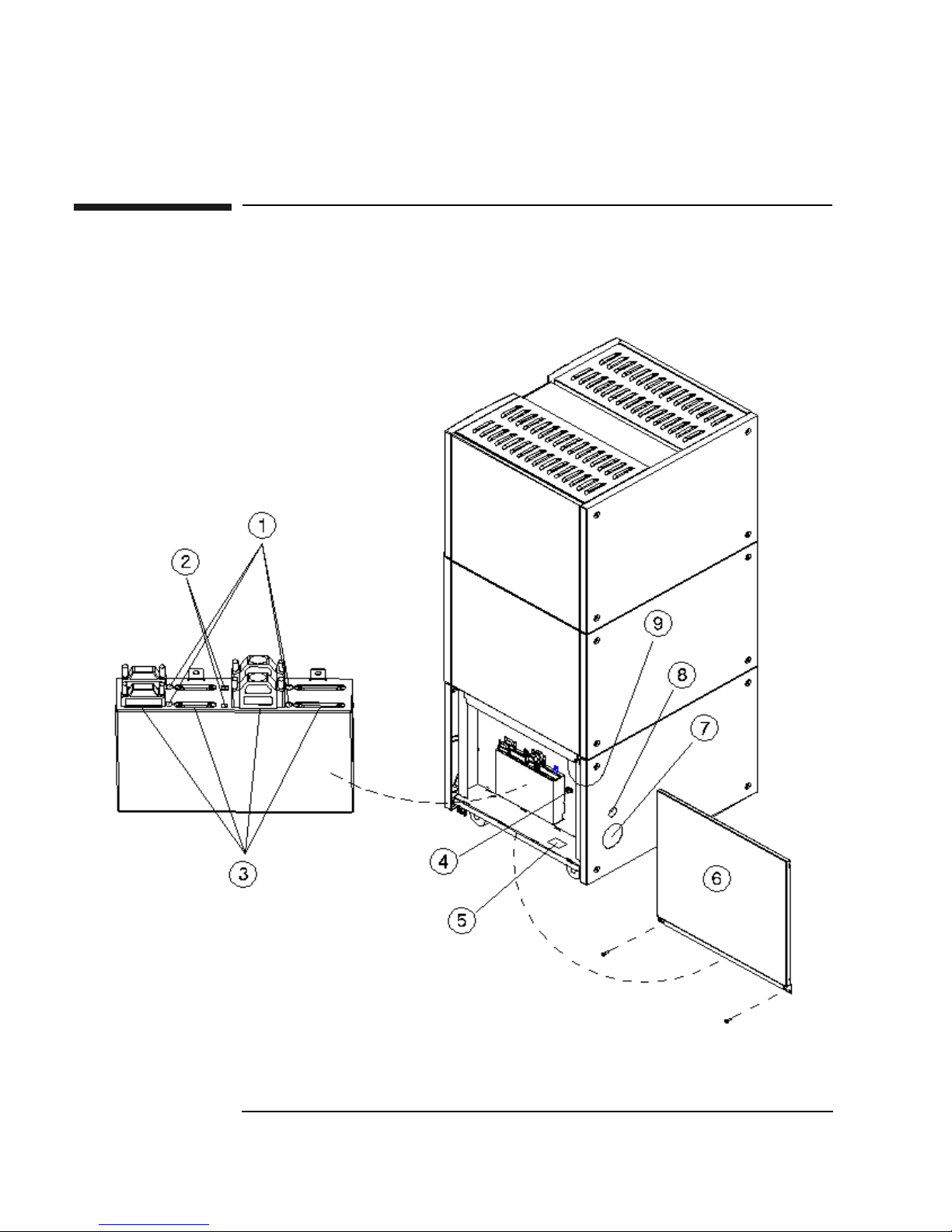
Figure 1-1 Right-Side Panel Features — 10-Drive Jukebox Shown
1-4 Chapter 1

Setting Up the Jukebox
Identifying Right-Side Panel Features
The numbers below correspond to the numbers in Figure 1-1 on the previous
page
Chapter 1: Setting
up the Disk Drive
Setting Up the
Jukebox
1 Active bus
indicator
Lit when the SCSI bus is active. There is an indicator
for each single-ended and each differential interface in
the jukebox.
2 SCSI interface
selection switch
Used to select either a single-ended or differential SCSI
interface on the SCSI interface board.
In 4- or 6-drive jukeboxes, there is one interface board.
In 10-drive jukeboxes, there are two interface boards,
designated Bus 1 and Bus 2. The interface selection
switch must be set individually for each board
3 SCSI ports Used for connecting SCSI cables to the interface board.
The interface board has two types of interface;
single-ended and differential. Each type of interface has
two ports
4 Power cord strain
relief clip
Used to route the power cord away from other
connectors and provide strain relief for the power cord
connection.
5 Product serial
number label
Needed for service calls. Write down your jukebox
serial number before you call your service
representative.
6 Access panel and
mounting screws
7 Cable access hole Used to pass SCSI and power cables through to the
8 Power switch The power switch is under the panel but can be operated
9 Power receptacle Receptacle for the jukebox power cord. Located on the
Chapter 1 1-5
Panel that covers the interface and power connection
components. The panel is secured by two screws on the
lower corners. (See the following note.)
Continued on the next page
inside of the jukebox.
through the hole in the panel. Turns power ON and OFF
to the jukebox.
bottom of the power distribution assembly.

Setting Up the Jukebox
Identifying Right-Side Panel Features
NOTE Two screws secure the customer access panel to the side of jukebox during shipment
from the factory. These screws are removed during unpacking but should be
replaced after installation is complete. If the jukebox is ever reshipped, these screws
must be in place to properly secure the access panel.
1-6 Chapter 1

Setting Up the Jukebox
Connecting the SCSI Cables to the Jukebox
Connecting the SCSI Cables to the Jukebox
In all configurations, the following cabling capabilities apply:
Interface types available Single-ended or differential SCSI, selected by
the interface selection switch on each
interface card
Chapter 1: Setting
up the Disk Drive
Setting Up the
Jukebox
Number of interface cards
available
Number of hosts This jukebox may be used in high availability
The maximum cable length you have available for connection to your host computer
system or other devices depends on which interface type you select. The following
table lists the maximum SCSI bus lengths available to you.
Table 1-1 Maximum SCSI External Cable Lengths (Assuming no devices internal to the
host computer)
Interface Type Maximum External Cable Length
Single-Ended SCSI
(50-pin high-density connector)
Differential SCSI
(68-pin high-density connector)
One card in 4- and 6-drive models,
two cards in 10-drive models
environments. High availability environments
can be complex and are not described in this
guide. Consult with your high-availability
vendor for installation and configuration.
3 meters (9.8 feet)
25 meters (82.0 feet)
NOTE Hewlett-Packard recommends that you use SCSI cables with thumbscrew
connectors. Clip type cables may be used if you first remove the mounted
thumbscrew studs with a flat blade screwdriver. If the thumbscrew studs are not
removed, interference between the cable and the studs may result.
Chapter 1 1-7

Setting Up the Jukebox
Choosing Your cabling Configuration
Choosing Your cabling Configuration
Pick the configuration that applies to your plans below. You will be shown the page
for the proper procedures.
See page
Standard Configuration
• The only peripheral on a bus
... and the jukebox has 4 or 6 drives 1-9
... and the jukebox has 10 drives and you are using two
host adapters
... and the jukebox has 10 drives and you are using one
host adapter
• The jukebox will share a bus with other devices 1-16
High Availability configuration
• Consult with your high-availability vendor —
1-12
1-14
1-8 Chapter 1

Setting Up the Jukebox
Connecting a 4- or 6-Drive Jukebox
Connecting a 4- or 6-Drive Jukebox
CAUTION Make sure that all peripheral devices connected to the host computer have been
properly shut down. If the host computer is connected to a network, check with the
system administrator before switching off power.
Removing the Customer Access Panel
1. Switch off power to the host computer before you connect the jukebox
NOTE The jukebox ships from the factory with two screws securing the bottom of the
customer access panel to the side of the jukebox. These screws are removed during
the process of unpacking and removing the jukebox from the shipping pallet.
Chapter 1: Setting
up the Disk Drive
Setting Up the
Jukebox
These screws may not have been replaced.
It is a good idea to use the screws to secure the access panel to the jukebox since
they must be in place if the jukebox is ever reshipped.
If you have to replace these screws, they are 6/32 x .437.
2. Remove the customer access panel by pulling on the bottom of the panel and
then lifting it off (see Figure 1-1). (If screws are installed, use a flatblade
screwdriver or T-15 Torx driver.)
Chapter 1 1-9
Setting Up the Jukebox
Connecting a 4- or 6-Drive Jukebox
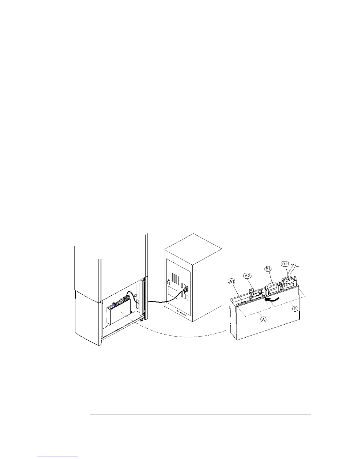
Refer to the following diagram in the next steps.
3. Select single-ended (“A”) or differential (“B”) interface using the SCSI
interface selection switch (see the arrow on the diagram ).
The diagram shows connecting a cable to the differential (“B”) interface.
4. Connect a cable between your host computer and either port of the jukebox
SCSI connectors of your selected interface type (the example diagram shows
using the “B2” port on the differential interface).
Route the cable through the slot at the bottom of the right side (“C”).
5. Plug a SCSI terminator into the unused SCSI port of interface type you chose
(the example diagram shows the terminator at “B1” because “B2” was used for
the cable ).
If you are using the differential interface, use a 68-pin high-density terminator. If
you are using the single-ended interface, use a 50-pin high-density active
terminator.
Figure 1-2 Connecting a 4- or 6-Drive Jukebox
6. Plug a SCSI terminator into one of the SCSI ports on the unused interface.
Only one terminator is necessary on an unused interface.
The example diagram shows the terminator on the single-ended interface
connector “A2” but the terminator could have been placed on “A1”.
Use an active terminator if you are terminating a single-ended interface.
1-10 Chapter 1

Setting Up the Jukebox
Connecting a 4- or 6-Drive Jukebox
If you are terminating a differential interface, use a 68-pin high-density
terminator. If you are terminating a single-ended interface, use a 50-pin
high-density active terminator.
7. To continue with the installation, go to “Connecting Power” in this Chapter.
Chapter 1: Setting
up the Disk Drive
Setting Up the
Jukebox
Chapter 1 1-11

Setting Up the Jukebox
Connecting a 10-Drive Jukebox as the Only Peripheral, Two Host
Adapters, Basic SCSI Addressing
Connecting a 10-Drive Jukebox as the Only
Peripheral, Two Host Adapters, Basic SCSI
Addressing
CAUTION Make sure that all peripheral devices connected to the host computer have been
properly shut down. If the host computer is connected to a network, check with the
system administrator before switching off power.
Removing the Customer Access Panel
1. Switch off power to the host computer before you connect the jukebox.
NOTE The jukebox ships from the factory with two screws securing the bottom of the
customer access panel to the side of the jukebox. These screws are removed during
the process of unpacking and removing the jukebox from the shipping pallet.
These screws may not have been replaced.
It is a good idea to use the screws to secure the access panel to the jukebox since
they must be in place if the jukebox is ever reshipped.
If you have to replace these screws, they are 6/32 x .437.
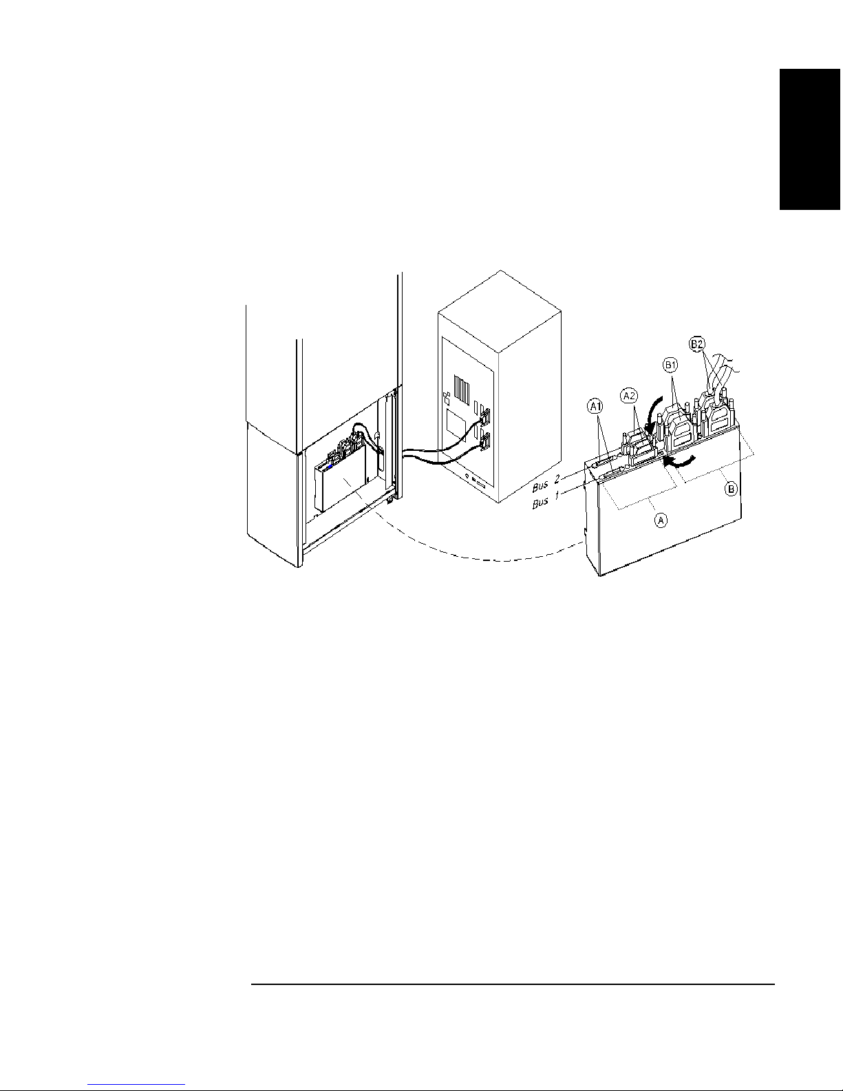
Refer to the following diagram in the next steps.
2. Select single-ended (“A”) or differential (“B”) interface using the SCSI
interface selection switch (see the arrow on the diagram ).
The diagram shows connecting a cable to the differential (“B”) interface.
3. Connect cables between the two host adapters on your host computer and two
SCSI interfaces on the interface module.
You can connect the two cables to two interfaces of the same type of different
types (single-ended or differential). If you use two different types of interface,
check that your jukebox application software supports this.
The diagram shows cable connections to the differential SCSI interface on both
interface cards at “B2.” One cable is connected to Bus 1 and the other cable is
connected to Bus 2.
Route the cables through the slot at the bottom of the right side (C).
1-12 Chapter 1
Setting Up the Jukebox
Connecting a 10-Drive Jukebox as the Only Peripheral, Two Host
Adapters, Basic SCSI Addressing
4. Remove the customer access panel by pulling on the bottom of the panel and
then lifting it off (see Figure 1-1). (If screws are installed, use a flatblade
screwdriver or T-15 Torx driver.)
Figure 1-3 Connecting a 10-Drive Jukebox, Two Host Adapters, Basic SCSI Addressing
Chapter 1: Setting
up the Disk Drive
Setting Up the
Jukebox
5. Plug a SCSI terminator into the unused SCSI connector of interface type you
chose (the example diagram shows terminators for the two differential interfaces
placed on the “B1” port for each interface ).
If you are using the differential interface, use a 68-pin high-density terminator. If
you are using the single-ended interface, use a 50-pin high-density terminator.
6. Plug a SCSI terminator into one of SCSI ports on each unused interface (the
example diagram shows the terminators on the single-ended port at “A2” for
both interfaces). The terminators can be placed on either port of the unused
interface.
Use a 50-pin high-density terminator for the single-ended interface or a 68-pin
terminator for the differential interface.
7. To continue with the installation, go to “Connecting Power” in this Chapter.
Chapter 1 1-13

Setting Up the Jukebox
Connecting a 10-Drive Jukebox, One Host Adapter, Bus 1 and 2
Daisy-Chained, LUN Addressing
Connecting a 10-Drive Jukebox, One Host
Adapter, Bus 1 and 2 Daisy-Chained, LUN
Addressing
CAUTION Make sure that all peripheral devices connected to the host computer have been
properly shut down. If the host computer is connected to a network, check with the
system administrator before switching off power.
Removing the Customer Access Panel
1. Switch off power to the host computer before you connect the jukebox.
NOTE The jukebox ships from the factory with two screws securing the bottom of the
customer access panel to the side of the jukebox. These screws are removed during
the process of unpacking and removing the jukebox from the shipping pallet.
These screws may not have been replaced.
It is a good idea to use the screws to secure the access panel to the jukebox since
they must be in place if the jukebox is ever reshipped.
If you have to replace these screws, they are 6/32 x .437.
2. Remove the customer access panel by pulling on the bottom of the panel and
then lifting it off (see Figure 1-1). (If screws are installed, use a flatblade
screwdriver or T-15 Torx driver.)
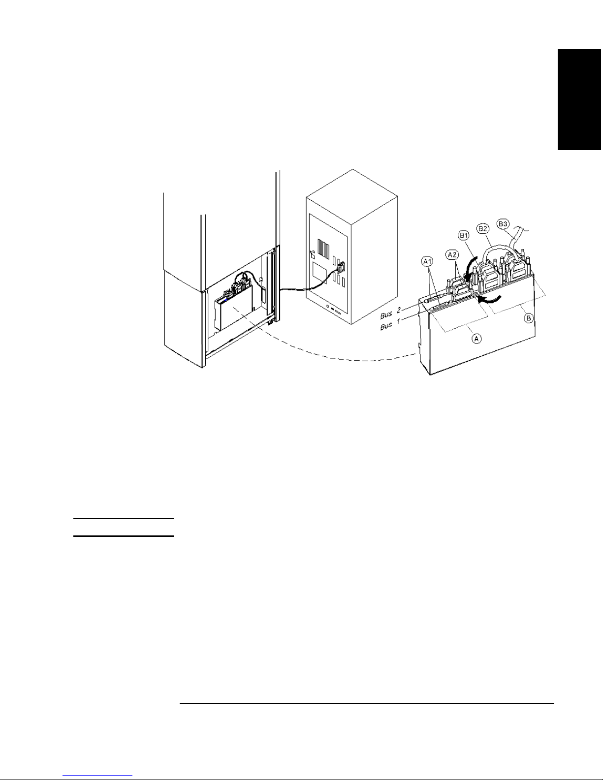
Refer to the following diagram in the notes steps.
3. Select single-ended (“A”) or differential (“B”) interface using the SCSI
interface selection switch (see the arrow on the diagram ).
The diagram shows connecting the host computer cable to a differential interface
port (“B3”). This connection is on the rear interface card so it is Bus 2.
Route the cable through the slot at the bottom of the right side.
4.
Connect a short cable between the interface card you have chosen to the
other Bus (the example diagram shows a cable (“B2”) between the
second Bus 2 port over to a differential port on Bus 1).
1-14 Chapter 1
Connecting a 10-Drive Jukebox, One Host Adapter, Bus 1 and 2
Daisy-Chained, LUN Addressing
Figure 1-4 Connecting a 10-Drive Jukebox, One Host Adapter,
Bus 1 and 2 Daisy-Chained, LUN Addressing
Setting Up the Jukebox
Chapter 1: Setting
up the Disk Drive
Setting Up the
Jukebox
5.
Terminate the daisy-chained bus by plugging a terminator into the
unused port of the second interface (the diagram show the terminator in
port “B1”). In this example you would use a 68-pin differential
terminator in “B1.”
A differential interface port uses a 68-pin high-density terminator. A
single-ended interface port uses a 50-pin high-density terminator.
The same cabling can be done using the single-ended ports.
CAUTION Do not daisy-chain between single-ended and differential interfaces.
6.
Plug a SCSI terminator into one of SCSI ports on each unused interface
(the example diagram shows the terminators on the single-ended port at
“A2” for both interfaces). The terminators can be placed on either port of
the unused interface.
Use a 50-pin high-density active terminator for the single-ended interface
or a 68-pin terminator for the differential interface.
7. To continue with the installation, go to “Connecting Power” in this Chapter.
Chapter 1 1-15

Setting Up the Jukebox
Connecting the Jukebox With Other SCSI Peripherals
Connecting the Jukebox With Other SCSI
Peripherals
NOTE Operating this jukebox with other peripherals on the same bus is supported, but not
recommended.
In most circumstances, the recommended configuration for this jukebox is as the
only device on a SCSI bus. However, your use of the jukebox may be such that other
devices could be connected to the bus without a loss of performance.
It is possible to connect this jukebox on a bus with additional peripherals in many
different ways (depending on your model):
• a 4- or 6-drive jukebox using basic SCSI addressing or Logical Unit Numbering
(LUN) addressing
• a 10-drive jukebox with one host adapter and with LUN addressing,
daisy-chaining Bus 1 and Bus 2 together or a 10-drive jukebox using two host
adapters, LUN addressing, and using both BUS 1 and Bus 2 interfaces
• a 10-drive jukebox with two host adapters and using LUN addressing
There are many issues that must be considered when connecting other devices on a
bus with this jukebox, including the following:
• how the jukebox is used; archiving, backup, near-line storage. What
performance must be maintained
• how the additional peripheral will be used. How much demand will it place on
the bus
• whether you will be mixing “wide” and “narrow” devices on the bus.
• whether you are using both internal and external segments on your SCSI host
adapter
• whether your bus is single-ended or differential
NOTE Appendix B provides a brief overview of SCSI and the issues you must consider
when placing other peripherals on the same bus with this jukebox.
1-16 Chapter 1

Connecting Power
1. Ensure that the power switch on the jukebox is OFF (“5” on Figure 1-1)
NOTE Use the power cord shipped with the jukebox.
2. Route the power cord through the strain relief clip (“4” on Figure 1-1) and close
the clip snugly around the cord.
3. Plug the socket end of the power cord into the power port on bottom of the
power distribution assembly ( “9” on Figure 1-1).
4. Continue to route the power cable down, through the long cable slot at the
bottom of the jukebox right side panel, and out through the cable access hole at
the lower left rear of the jukebox (“7” on Figure 1-1).
Setting Up the Jukebox
Connecting Power
Chapter 1: Setting
up the Disk Drive
Setting Up the
Jukebox
5. Plug the other end of the power cord into a three-hole grounded outlet.
6. Press the power switch ON (“8” on Figure 1-1)
When power is applied, TESTING and NOT READY alternately display. Once
the poweron test completes (approximately 1.5 minutes), READY displays.
NOTE If DEVICE FAILED displays. See “Troubleshooting” in Chapter 3 for
troubleshooting procedures.
7. Refer to Chapter 3, “Operating the Jukebox” for instructions on setting the SCSI
addresses, loading optical disks into the jukebox, setting a password, etc.
NOTE Continue on to “Configuring Write Verify” on the next page.
Chapter 1 1-17

Setting Up the Jukebox
Configuring Write Verify
Configuring Write Verify
The write verify configuration ensures that data is written reliably to an optical disk.
The jukebox ships with write verify enabled. Many software applications also
default to this method of writing.
Writing data on a magneto-optical disk requires two passes. The first pass erases the
data in the sector to which data will be written. The second pass writes new data to
that sector.
When write verify is configured to ON, an additional pass is made over the sector.
This third pass verifies that all data is written correctly to the sector. To add to the
reliability of your data, Hewlett-Packard recommends that you maintain the default
ON setting for write verify. Note that when write verify is ON, write operations take
more time.
If you choose to change the write verify configuration to OFF, refer to “Configuring
Operating Configurations” in Chapter 3.
NOTE Continue on to “Installing the Wheel Chocks ” on the next page.
1-18 Chapter 1
 Loading...