

Page 1

HP Surestore Tape Library 10/180
56 Cartridge Array Installation
(for HP Field Service Use Only)
CAUTION: Remote res olution mus t be at te m pt ed prior to au th orization of on-s it e service.
Note to Customer Engineer: This installat ion may add new techn ology to the lib rary
that older us er’s gu ides do not address. Plea s e remind the c ustomer t hat the latest us er
docume nta tio n is av ailable fro m th e H P C ustomer Ca re website: http://www.hp.com/go/
support.
■ Materials Included
Table 1. Materials List
Part Quantity
Cartridge Array Installation Guide 1
Cartridge Unit 1
Instruction
6-cell Array 10
Retainer Clips 2
Retainer Labels 2
■ Installation Notes
• Confirm with the customer System Administrator that the tape library can be powered
off.
• Observe proper power down and power on procedures, as described in the
Installation or Service Manual.
• If you install or replace a Cartridge Array, you must mark the appropriate box on the
Drive Location Label. The Drive Location Label is located on the inside of the rear
library door, just below the UL label.
62213 1
Page 2

■ Cartridge Array Install
1. Have the operator take the tape library and all drives off-line.
2. Go to the back of the machine and power OFF the tape library.
3. Open the front door with the tape library key.
4. Move the robotic hand to the top of the tape library, and rotate it towards the cartridge
access port.
Before beginning the installation procedure please note the bracket on the ceiling of
the library so you don’t hit your head.
1. Install the arrays from the bottom to the top of each column; start with Panel 1, Column
2, and finish at Panel 1, Column 3. Move the robotic hand down to the bottom of the
tape library before installing the final array in each column.
2. Apply one retainer clip label to the front of each of the retainer clips.
62213 2
Page 3

1. With the raised are a of one retaine r clip facing up, slide the prongs unde r neath the first cell
of the top array in columns 3 and 4. Make sure that the lip on the front of the retainer clip
is firmly fixed to the tape library wall by gently pul ling the clip towards you to ensure that
the retainer clip lock is snapped into position at the back array wall (see Figure 1).
Figure 1. Array and Retainer Clips
62213 3
Page 4
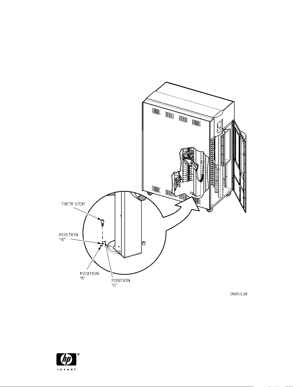
2. Remove the left theta stop from its current position (A), and install it at the new position
(B), the center position, shown in Figure 2
CAUTION: This stop must be instal led. If it is not , it could cause damage to
the hand and/or the rear cover
.
Figure 2. Theta Stop
3. Close the front door of the tape library, and lock the latches. Power on the tape library.
Verify that the tape library initializes and audits. If initialization and audit occurs, then the
installation was successful.
REV D
EC 111770
62213
Copyright ©2001
Hewlett-Packard Company/
Storage Technology Corp
Edition 11/2001
 Loading...