

Page 1

HPE StoreVirtual 3200 Storage User Guide
Abstract
This guide provides instructions for configuring individual storage systems, adding new disk drives
or storage systems to existing configurations, and using remote support.
Part Number: 839939-003
Published: March 2017
Edition: 3
Page 2

©
2016, 2017 Hewlett Packard Enterprise Development LP
Notices
The information contained herein is subject to change without notice. The only warranties for Hewlett Packard
Enterprise products and services are set forth in the express warranty statements accompanying such
products and services. Nothing herein should be construed as constituting an additional warranty. Hewlett
Packard Enterprise shall not be liable for technical or editorial errors or omissions contained herein.
Confidential computer software. Valid license from Hewlett Packard Enterprise required for possession, use,
or copying. Consistent with FAR 12.211 and 12.212, Commercial Computer Software, Computer Software
Documentation, and Technical Data for Commercial Items are licensed to the U.S. Government under
vendor's standard commercial license.
Links to third-party websites take you outside the Hewlett Packard Enterprise website. Hewlett Packard
Enterprise has no control over and is not responsible for information outside the Hewlett Packard Enterprise
website.
Acknowledgments
Microsoft® and Windows® are either registered trademarks or trademarks of Microsoft Corporation in the
United States and/or other countries.
Page 3

Contents
Product overview.........................................................................................7
Operating the storage system.................................................................. 15
Product configurations.........................................................................................................................7
Features and benefits..........................................................................................................................7
Terminology......................................................................................................................................... 7
Component identification.....................................................................................................................8
Storage controller enclosure ....................................................................................................8
Recovery/Power button.......................................................................................................... 12
HPE StoreVirtual 3000 drive enclosure.................................................................................. 12
Locating the product serial number on the hardware........................................................................ 13
Locating the product serial number in the Management Console..................................................... 14
Powering on the storage system....................................................................................................... 15
Powering off the storage system....................................................................................................... 15
Status LED descriptions.................................................................................................................... 15
Common status LEDs.............................................................................................................15
Storage controller enclosure controller module status LEDs..................................................17
Ethernet LED statuses.................................................................................................18
Fibre channel LED status.............................................................................................18
External SAS LED status.............................................................................................19
Data port (SAS connected JBODs) LED status........................................................... 19
Drive enclosure I/O module status LEDs................................................................................19
Safely rebooting a storage controller.................................................................................................20
Adding storage system capacity..............................................................22
End-to-end process for adding drives and drive enclosures............................................................. 22
Adding disk drives and drive enclosures................................................................................ 22
Verifying the state of the new drives and enclosures..............................................................22
Using the StoreVirtual Management Console to scale up the storage system.......................23
Verifying the added capacity in the StoreVirtual Management Console................................. 23
Adding disk drives............................................................................................................................. 23
Adding a drive enclosure...................................................................................................................25
Installing the rail kits............................................................................................................... 25
Installing the enclosure...........................................................................................................27
Adding StoreVirtual 3200 storage systems....................................................................................... 28
Adding a new storage system to an existing configuration.....................................................28
HPE StoreVirtual Multi-Site SAN design..................................................30
Multi-Site SAN features..................................................................................................................... 30
Design considerations for a Multi-Site SAN.......................................................................................30
Designing the network for the Multi-Site SAN................................................................................... 30
Calculating bandwidth....................................................................................................................... 31
Inter-site Bandwidth based on the number of storage systems at a site........................................... 31
Managing the network...............................................................................32
Contents 3
Page 4

Introduction........................................................................................................................................32
Network cabling configurations..........................................................................................................32
Connecting the StoreVirtual 3200 Storage system to the network......................................... 32
Network configuration for array enclosure with 1 GbE controller modules (two port).............32
Network configuration for array enclosure with 1 GbE controller modules (four port)............ 33
Network configuration for array enclosure with 10 GbE/10GBase-T controller modules
(two port).................................................................................................................................34
Network configuration for array enclosure with Fibre Channel controller modules (two
port)........................................................................................................................................ 35
Connecting the StoreVirtual 3000 drive enclosure................................................................. 36
Connecting to one drive enclosure.............................................................................. 36
Connecting to two drive enclosures............................................................................. 36
Connecting to three drive enclosures.......................................................................... 37
Bonded interface configuration..........................................................................................................37
Multipathing with iSCSI configurations ............................................................................................. 40
iSCSI multipathing with DSM or MEM.................................................................................... 40
iSCSI multipathing without DSM or MEM............................................................................... 41
Removing and replacing hardware components....................................42
Customer self repair (CSR)............................................................................................................... 42
Identifying the spare part number...........................................................................................42
Identifying swappable parts.................................................................................................... 42
Accessing component replacement videos............................................................................ 42
Parts-only warranty service ................................................................................................... 42
Replaceable parts list........................................................................................................................ 43
Warnings and precautions.................................................................................................................50
Preventing electrostatic discharge..........................................................................................50
Equipment symbols................................................................................................................ 51
Required tools................................................................................................................................... 51
Replacing a disk drive....................................................................................................................... 52
Verifying disk drive failure.......................................................................................................52
Removing a disk drive............................................................................................................ 52
Installing a disk drive.............................................................................................................. 53
Verifying disk drive operation..................................................................................................55
Replacing a controller module...........................................................................................................56
Prerequisites...........................................................................................................................56
Verifying controller module failure...........................................................................................56
Removing a controller module................................................................................................ 56
Installing a controller module..................................................................................................57
Completing the controller module replacement...................................................................... 58
Replacing a drive enclosure I/O module............................................................................................58
Verify I/O module failure......................................................................................................... 58
Removing an I/O module........................................................................................................58
Installing an I/O module..........................................................................................................59
Verifying I/O module operation............................................................................................... 59
Replacing a power supply module.....................................................................................................60
Verifying power supply failure.................................................................................................60
Removing a power supply...................................................................................................... 60
Installing a power supply........................................................................................................ 61
Verifying power supply operation............................................................................................61
Replacing a fan module.....................................................................................................................61
Before you begin.....................................................................................................................61
Verifying fan module failure.................................................................................................... 61
Removing a fan module..........................................................................................................62
Installing a fan module............................................................................................................62
4 Contents
Page 5

Verifying fan module operation...............................................................................................62
Replacing the UID health module......................................................................................................62
Verifying UID health module failure........................................................................................ 62
Removing the UID health module...........................................................................................63
Installing the UID health module.............................................................................................65
Verifying UID health module operation................................................................................... 65
Replacing the enclosure backplane...................................................................................................65
Before you begin.....................................................................................................................65
Removing the enclosure backplane........................................................................................66
Installing the enclosure backplane..........................................................................................68
Verifying enclosure backplane operation................................................................................69
Replacing a Fibre Channel SFP........................................................................................................69
Removing a Fibre Channel SFP............................................................................................. 69
Installing a Fibre Channel SFP...............................................................................................69
Verifying Fibre Channel SFP operation.................................................................................. 70
Removing and replacing the fan control card cable assembly.......................................................... 70
Before removing the fan control card cable assembly............................................................70
Removing the fan control card cable assembly...................................................................... 71
Installing the fan control card assembly..................................................................................72
Removing and replacing Ethernet cables..........................................................................................73
Replacing the cache backup battery................................................................................................. 73
Verifying cache backup battery failure....................................................................................73
Removing the cache backup battery...................................................................................... 73
Installing the cache backup battery........................................................................................ 75
Verifying cache backup battery operation...............................................................................77
Replacing the intercontroller link (ICL) ............................................................................................. 77
Before you begin.....................................................................................................................77
Removing the ICL...................................................................................................................77
Installing the ICL.....................................................................................................................79
Verifying ICL operation........................................................................................................... 80
Migrating data from other StoreVirtual Storage systems...................................................................80
Remote support......................................................................................... 81
Overview............................................................................................................................................81
Setting up customer information........................................................................................................81
Entering and modifying customer information........................................................................ 81
Remote Support settings ..................................................................................................................82
Hewlett Packard Enterprise Remote Support page................................................................ 82
Configuring and modifying Remote Support...........................................................................84
Proxy settings......................................................................................................................... 84
RSvS alarms......................................................................................................................................86
Viewing RSvS alarms............................................................................................................. 86
Support mode......................................................................................................................... 87
Troubleshooting.........................................................................................88
Green activity LEDs do not work as expected during certain activities............................................. 88
A disk enclosure from a 3PAR StoreServ installed into a StoreVirtual 3200 Storage system
results in the enclosure status as unknown ..................................................................................... 88
An iSCSI volume that becomes unavailable for approximately 60 seconds or less may cause
data unavailability..............................................................................................................................88
RAID array remains degraded after hot spares rebuild..................................................................... 89
Servicing controller incorrectly presented in the SVMC.................................................................... 89
Contents 5
Page 6

Websites..................................................................................................... 91
Support and other resources................................................................... 92
Accessing Hewlett Packard Enterprise Support................................................................................ 92
Accessing updates............................................................................................................................ 92
Customer self repair.......................................................................................................................... 92
Remote support.................................................................................................................................93
Warranty information......................................................................................................................... 93
Regulatory information...................................................................................................................... 93
Documentation feedback...................................................................................................................94
Warranty and regulatory information.......................................................95
Warranty information......................................................................................................................... 95
Regulatory information...................................................................................................................... 95
Belarus Kazakhstan Russia marking...................................................................................... 95
Turkey RoHS material content declaration............................................................................. 96
Ukraine RoHS material content declaration............................................................................96
6 Contents
Page 7

Product overview
The HPE StoreVirtual 3200 Storage system is a dual-controller hardware platform that provides highavailability storage in a single enclosure solution at an entry level price.
Product configurations
• HPE StoreVirtual 3200 storage system can be scaled to add another storage system.
• The basic HPE StoreVirtual 3200 Storage includes an array enclosure with dual storage controller
modules and either 12 LFF drive bays or 25 SFF drive bays. The storage system capacity can scale up by
adding up to three external drive enclosures. Storage systems are available in the following configurations:
◦ Four 1 GbE ports (base configuration)
◦ Eight 1 GbE ports
◦ Four 10 GbE, SFP+, or 10GBase-T ports
◦ Four 8 Gb/16 Gb Fibre Channel ports
Features and benefits
Product features and supported options are subject to change. Online documentation describes the latest
product and product family characteristics, including currently supported features, options, technical
specifications, configuration data, related optional software, and product warranty information.
NOTE:
Review the QuickSpecs for a complete list of supported servers, operating systems, disk drives, and
options. The QuickSpecs are available from the product page.
Terminology
Following are definitions for the commonly used product terms:
• Array enclosure – A chassis with two storage controllers, drives, power supplies, and fan modules.
• Chassis – A specialized casing designed to hold, cover, power, cool and allow communication between
two storage controllers or two I/O modules, drives, two power supplies and fan modules.
• Drive enclosure - A chassis with two I/O modules, drives, power supplies, and fan modules. This is
commonly referred to as a JBOD.
• Enclosure – A chassis with two storage controllers or two I/O modules, drives, power supplies, and fan
modules.
• I/O module – The canister that provides SAS connectivity in the enclosure.
• Management group – One or more storage pools that have a common management configuration.
• Storage controller – The canister containing the storage computer with independent I/O paths to the
storage network.
• Storage pool – An aggregation of storage resources from one or more storage systems from which
volumes can be provisioned. For example, one storage pool may contain one array enclosure connected
to three drive enclosures. Another storage pool may contain two array enclosures.
• Storage system – The hardware that consists of the array enclosure with one or more storage controllers
and all of the SAS-connected drive enclosures.
Product overview 7
Page 8
Component identification
3 4
1
2
1
2
3 4
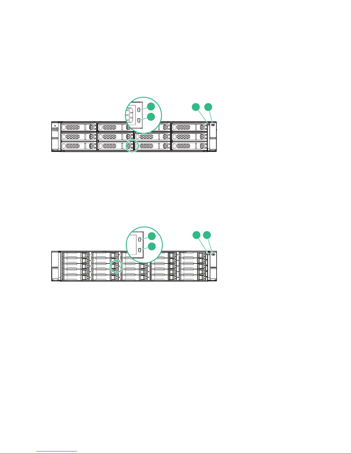
The following figures identify the controllers, connectors, and indicators on the array enclosure and the drive
enclosure.
Storage controller enclosure
The array enclosure is available in either an LFF configuration with 12 drive bays, or an SFF configuration
with 25 drive bays. There are four controller configurations available.
Figure 1: HPE StoreVirtual 3200 Storage LFF front view
1. Disk drive locate UID 3. System status LED
2. Disk drive status LED 4. System locate UID/push button
Figure 2: HPE StoreVirtual 3200 Storage SFF front view
1. Disk drive locate UID 3. System status LED
2. Disk drive status LED 4. System locate UID/push button
8 Component identification
Page 9
1 2 43 1 62 7 4 8 95
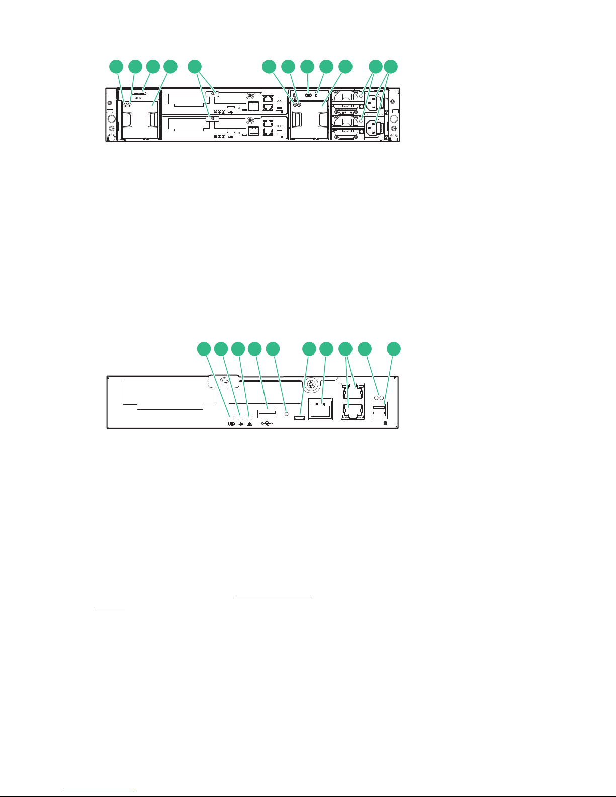
Figure 3: HPE StoreVirtual 3200 Storage rear view
1 2 3 4 5 6 7 8 9 10
1. Fan locate UID 6. System locate UID/push button
2. Fan status LED 7. System status LED
3. Pullout tab with system serial number label 8. Power supply status LED
4. Fan module 9. Power supply module
5. Controller module
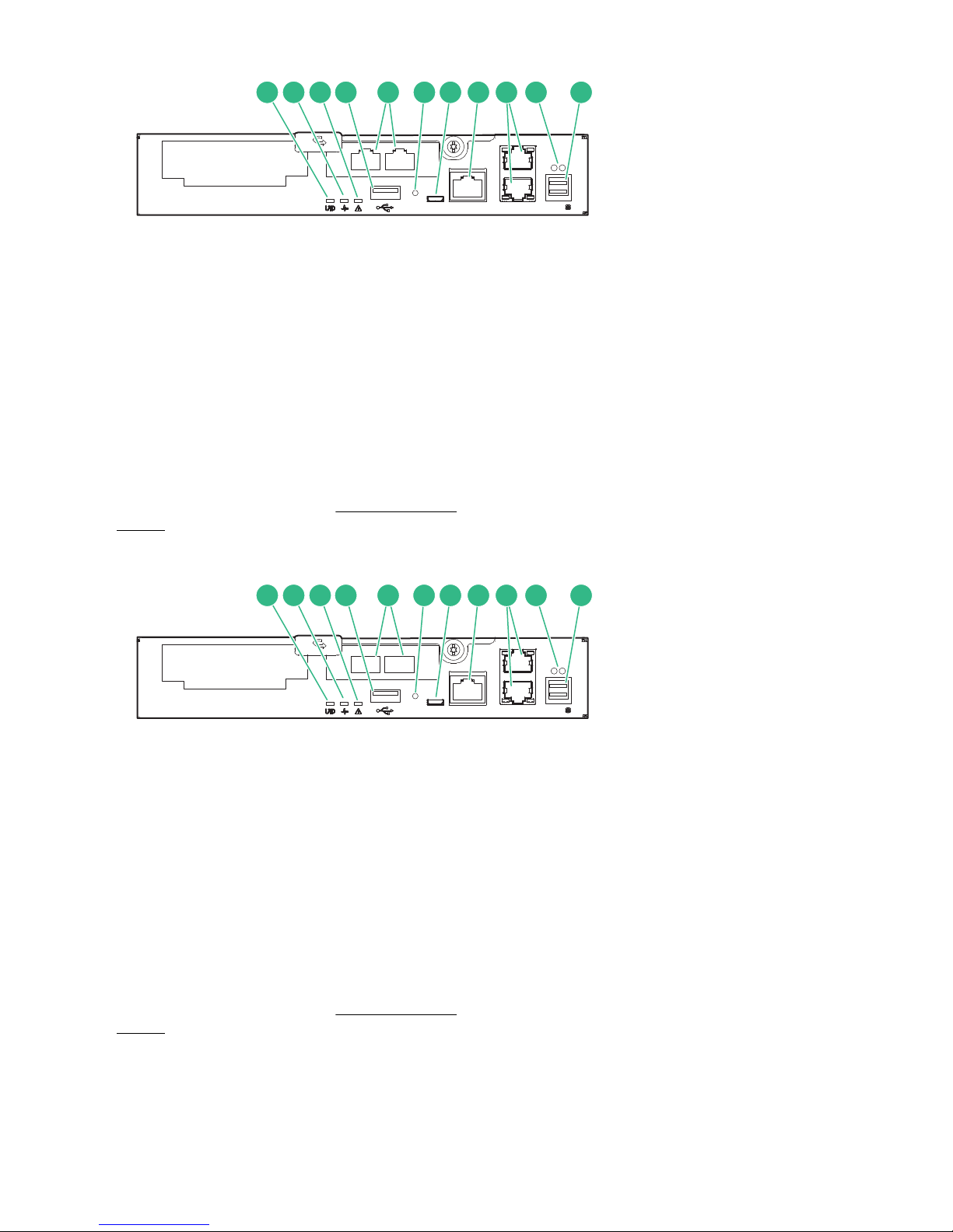
Figure 4: HPE StoreVirtual 3200 Storage 1 GbE controller module (2 port)
1. Controller locate UID
2. Controller status LED
3. Controller fault LED
4. USB type A port
5. Recovery/power button (See Recovery/Power
button on page 12).
6. Service port (Micro-B USB)
7. Management port (MGMT)
8. 1 GbE ports
9. Data port status LEDs
10. SAS data port to optional drive enclosure (DP-1)
Product overview 9
Page 10
1 2 3 4 5 76 8 9 10 11
Figure 5: HPE StoreVirtual 3200 Storage 1 GbE controller module (4 port)
1 2 3 4 5 76 8 9 10 11
1. Controller locate UID 7. Service port (Micro-B USB)
2. Controller status LED 8. Management port (MGMT)
3. Controller fault LED 9. 1 GbE ports
4. USB type A port 10. Data port status LEDs
5. 1 GbE ports 11. SAS data port to optional drive enclosure (DP-1)
6. Recovery/power button (See Recovery/Power
button on page 12).
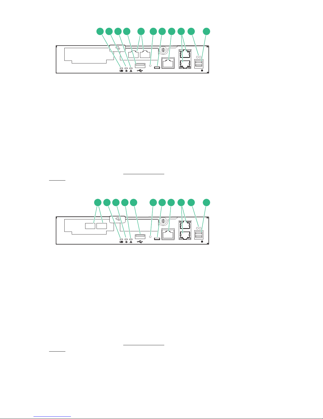
Figure 6: HPE StoreVirtual 3200 Storage 10 GbE controller module (2 port)
1. Controller locate UID 7. Service port (Micro-B USB)
2. Controller status LED 8. Management port (MGMT)
3. Controller fault LED 9. 1 GbE ports
4. USB type A port 10. Data port status LEDs
5. 10 GbE SFP ports 11. SAS data port to optional drive enclosure (DP-1)
6. Recovery/power button (See Recovery/Power
button on page 12).
10 Product overview
Page 11
1 2 3 4 5 76 8 9 10 11
Figure 7: HPE StoreVirtual 3200 Storage 10GBase-T controller module (2 port)
2 3 4 51 76 8 9 10 11
1. Controller locate UID 7. Service port (Micro-B USB)
2. Controller status LED 8. Management port (MGMT)
3. Controller fault LED 9. 1 GbE ports
4. USB type A port 10. Data port status LEDs
5. 10GBase-T ports 11. SAS data port to optional drive enclosure (DP-1)
6. Recovery/power button (See Recovery/Power
button on page 12).
Figure 8: HPE StoreVirtual 3200 Storage 8Gb/16 Gb Fibre Channel controller module (2 port)
1. 8 Gb/16 Gb Fibre Channel ports 7. Service port (Micro-B USB)
2. Controller locate UID 8. Management port (MGMT)
3. Controller status LED 9. 1 GbE ports
4. Controller fault LED 10. Data port status LEDs
5. USB type A port 11. SAS data port to optional drive enclosure (DP-1)
6. Recovery/power button (See Recovery/Power
button on page 12).
Product overview 11
Page 12
Recovery/Power button
3 4
1
2
1
2
3 4
The recovery/power button is a recessed button that requires an unfolded paper clip or other small pointed
device to press it. The recovery/power has these functions depending upon the state of the controller:
Press the recovery/power button for one second:
• If the controller power is ON, and the OS is running, a safe shutdown is performed and the controller is
powered off.
• If the controller power is OFF (but the enclosure power is ON), the CPU is powered on and causes a
reboot of the controller.
HPE StoreVirtual 3000 drive enclosure
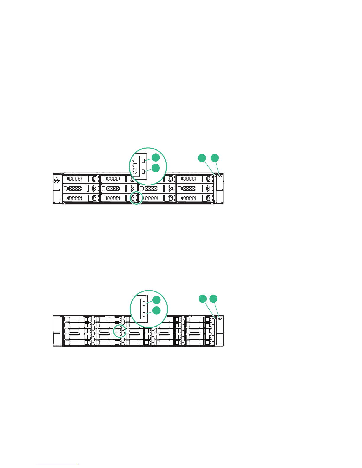
The HPE StoreVirtual 3000 drive enclosure is available in either an LFF configuration with 12 drive bays, or
an SFF configuration with 25 drive bays. The components on the rear of the drive enclosure are identical for
both the LFF and SFF configurations.
Figure 9: HPE StoreVirtual 3000 LFF front view
1. Disk drive locate UID 3. System status LED
2. Disk drive status LED 4. System locate UID
/push button
Figure 10: HPE StoreVirtual 3000 SFF front view
1. Disk drive locate UID 3. System status LED
2. Disk drive status LED 4. System locate UID/push button
12 Recovery/Power button
Page 13
16 15117 1416
5432 6 7 8 91510
11 13
1211
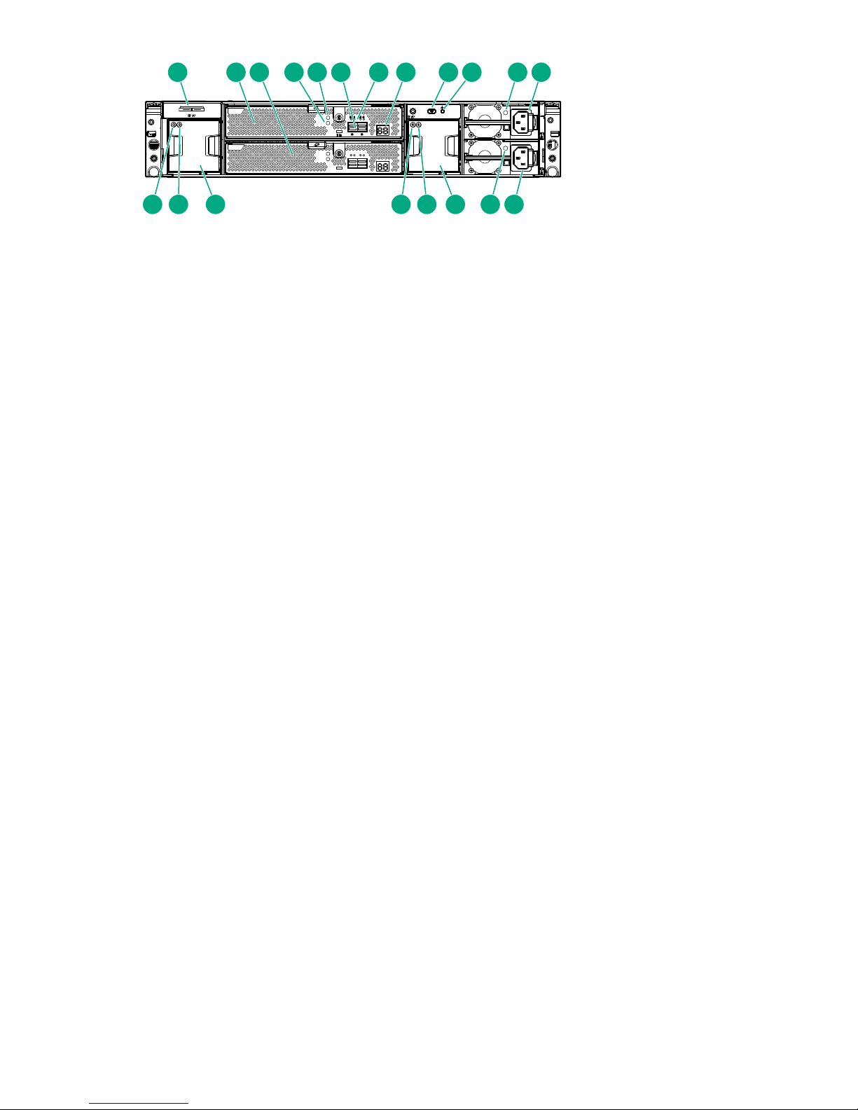
Figure 11: HPE StoreVirtual 3000 drive enclosure rear view
1. Pullout tab with serial number label 10. System status LED
2. I/O module (slot 1) 11. Power supply status LED
3. I/O module (slot 2) 12. Power supply 1
4. I/O module status LED 13. Power supply 2
5. I/O module locate UID 14. Fan Module 2
6. SAS data ports 15. Fan status LED
7. Data port status LEDs 16. Fan locate UID
8. Seven-segment display 17. Fan Module 1
9. System locate UID/push button
Locating the product serial number on the hardware
It may be necessary to provide the product serial number for support or service.
Procedure
1. Locate the serial number label on the rear of the enclosure.
2. Pull the tab out to view the label.
Locating the product serial number on the hardware 13
Page 14
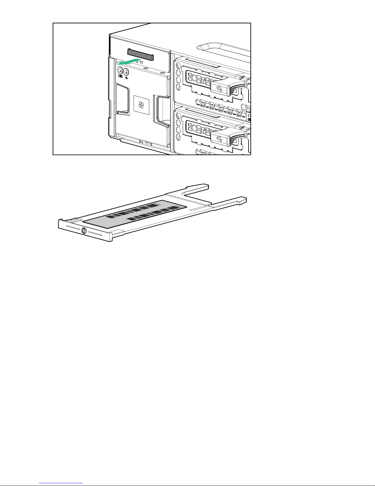
Figure 12: Pullout tab location
Serial No.
Product No.
Figure 13: Serial number label
Locating the product serial number in the Management
Console
Procedure
1. From the main menu, select Storage System.
2. Select Storage System Report. The serial number is located in the Warranty Information section
14 Locating the product serial number in the Management Console
Page 15
Operating the storage system
For information on using the HPE StoreVirtual Management Console, see the StoreVirtual Management
Console online help or user guide.
Powering on the storage system
NOTE:
There is no power switch on the enclosure. Power is applied to the enclosure immediately when
connected to a live power source.
Procedure
1. Connect a power cord from the power source to each drive enclosure.
IMPORTANT:
The best practice is to power on the drive enclosures before the array enclosure. This order ensures
that all disk drives have spun up and that all of the storage is discovered.
2. Connect two power supply cords from the power source to the array enclosure.
3. Wait a few minutes for all the components to complete their power-on self test routines and complete
initialization, then verify the system operating status by checking the LED displays. For more information
on interpreting the LED displays, see Status LED descriptions on page 15.
Powering off the storage system
Currently, there is not a way to power off the entire storage system (controllers and drive enclosures) from a
software interface. To power off a storage controller, use the Recovery/Power button on the rear of the
controller. (See Recovery/Power button on page 12 for more information.) To power off a disk enclosure,
remove the power cord from the wall socket.
Status LED descriptions
Various LEDs display the current operating status of the array enclosure and the drive enclosures. If a
problem is indicated, perform the following to help identify the source of the problem:
• Check all cable connections between the devices.
• Check the availability of the power source.
• For the location of the array enclosure LEDs, see Storage controller enclosure on page 8.
• For the location of the drive enclosures LEDs, see HPE StoreVirtual 3000 drive enclosure on page 12.
Common status LEDs
The following LEDs are used on both the array enclosure and the drive enclosure.
Operating the storage system 15
Page 16
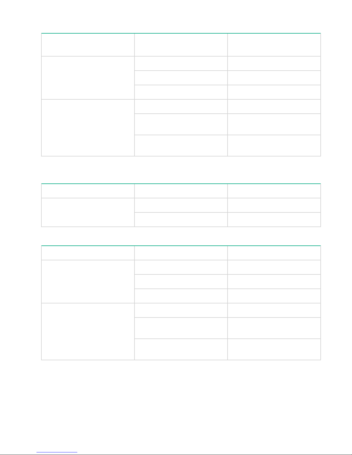
Table 1: Front panel system status LEDs
Indicator
1
Display Description
System status LED Green on Normal operation.
Amber on Critical fault.
Amber flashing Non-critical fault.
Locate UID Off Normal operation.
Blue on Location requested. Safe to power
off.
Blue flashing Location requested. Do not
remove.
1
These indicators are also located on the rear panel directly above fan 2.
Table 2: Power supply module status LED
Indicator Display Description
Status LED Green on Normal operation
Green off
Fault or no power
Table 3: Fan module status LEDs
Indicator Display Description
Status LED Green on Normal operation
Amber on Fault
All LEDS off Fault or no power
Locate UID Off Normal operation
Blue on Location requested. Safe to
remove.
Blue flashing Location requested. Do not
remove.
16 Operating the storage system
Page 17

Table 4: Disk drive status LEDs
Blue UID LED Bicolor (green/amber) power or
status LEDs
Off Off No power or an inactive spare
Off Green on Powered on, no I/O, no fault
Off Green flicker Powered on, active I/O, no fault
Off Amber on Fault
Off Amber flash
Off Amber Flicker Powered on, active I/O, predictive
On Green on Manually initiated locate, no I/O,
On Green flicker Manually initiated locate, active
Flash Green on Manually initiated locate, no I/O,
Description
Powered on, no I/O, predictive
failure
failure
no fault, safe to remove
I/O, no fault, safe to remove
no fault, do not remove
Flash Green flicker Manually initiated locate, active
I/O, no fault, do not remove
On Amber on Automatically initiated locate, fault,
safe to remove
Flash Amber on Automatically initiated locate, fault,
do not remove
Storage controller enclosure controller module status LEDs
The following LEDs are used to verify array enclosure controller module operation.
Table 5: Array controller module status LEDs
Blue UID LED Green
power LED
Off Off Off No power
Off On Off Powered on, no fault
Off Off Solid Fault
Amber status
LED
Description
Off On Flash Predictive failure
Table Continued
Storage controller enclosure controller module status LEDs 17
Page 18
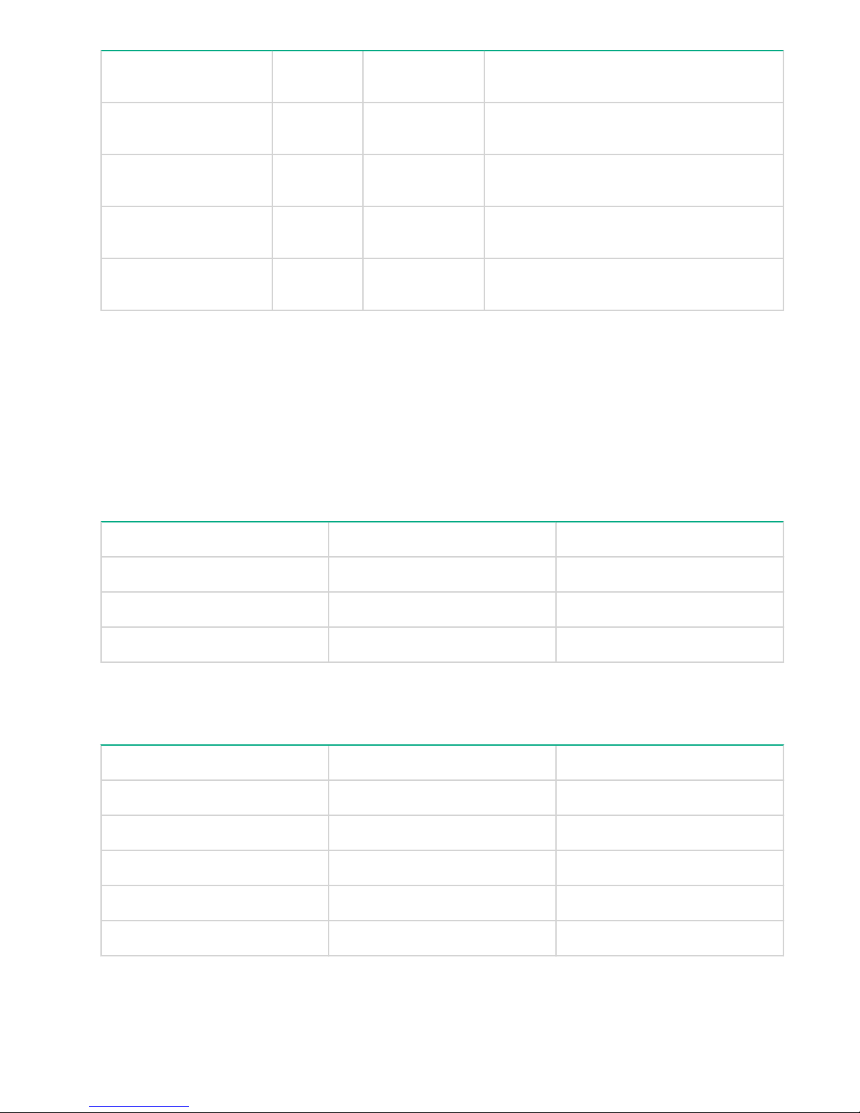
Blue UID LED Green
On On Off Manually initiated locate, no fault, safe to
Flash On Off Manually initiated locate, no fault, do not
On Off On Automatically initiated locate, fault, safe to
Flash Off On Automatically initiated locate, fault, do not
Ethernet LED statuses
The LED statuses described in the Ethernet Led statuses table behave the same way for the following
components:
• Management ports
• Onboard 1 GbE LEDs
• 1 GbE LOM LEDs
• 10 GbE LOM LEDs
power LED
Amber status
LED
Description
remove
remove
remove
remove
Table 6: Ethernet LED statuses
Green LED Amber LED Description
Off Off
Off On Link without activity
Flash On Link with activity
Fibre channel LED status
Table 7: FC LED statuses
Green LED Amber LED Description
Off Off
On Off Link at high speed, no activity
Flicker Off Link at high speed with activity
Off On No link or no cable connected
Fault or no power
Fault or no power
On On Link at low speed, no activity
18 Ethernet LED statuses
Table Continued
Page 19

Green LED Amber LED Description
Flicker On Link at low speed with activity
Flash Flash (opposite green LED) Location requested
External SAS LED status
Table 8: External SAS LED statuses
Green LED Amber LED Description
Off Off
On Off Link at high speed, no activity
Flicker Off Link at high speed with activity
Off On No link or no cable connected
On On Link at low speed, no activity
Flicker On Link at low speed, with activity
Flash Flash (opposite of the green LED) Location requested
Data port (SAS connected JBODs) LED status
Table 9: Data port SAS LED statuses
Green LED Amber LED Description
Off Off
On Off Link at high speed, no activity
Fault or no power
Fault or no power
Flicker Off Link at high speed with activity
Off On No link or no cable connected
On On Link at low speed, no activity
Drive enclosure I/O module status LEDs
The following LEDs and indicators are used to verify drive enclosure I/O module operation.
External SAS LED status 19
Page 20

Table 10: I/O module status LEDs
Indicator Display Description
7-segment display On Indicates the enclosure number or
an error/warning code
Data ports (DP-1, DP-2) Green on, amber off Link at high speed with no activity
Green flashing, amber off Link at high speed with activity
Green on, amber on Link at low speed with no activity
Green flashing, amber on Link at low speed with activity
Green off, amber on No link or no cable connected
Green flashing, amber flashing Location requested
I/O module status LED Green on, amber off Normal operation
Green flashing, amber off Shutdown in progress, no fault
Green off, amber on Fault
Green flashing, amber on Shutdown in progress, fault
Green flashing, amber flashing Shutdown in progress
Locate UID Off Normal operation
Blue on Location requested. Safe to
Blue flashing Location requested. Do not
Safely rebooting a storage controller
Safely rebooting a storage controller includes failing over the controller before you reboot, and failing back
when the controller comes back online.
remove.
remove. Indicates that
maintenance is in progress. For
example, firmware is updating.
20 Safely rebooting a storage controller
Page 21

Procedure
1. Fail over the storage controller
2. Reboot the storage controller
3. Fail back the storage controller
a. On the StoreVirtual menu, select Storage Systems.
a. On the navigation pane, select the storage system, and then select Actions > Fail over storage
controller on the content pane.
b. Select the storage controller from the list if more than one is listed.
a. Select the check box next to the storage controller status, and then click Yes, fail over storage
controller.
a. On the StoreVirtual menu, select Storage Controllers.
b. On the navigation pane, select the storage controller, and then select Actions > Power off or reboot
on the content pane.
c. Click Reboot.
d. Enter the number of minutes for the system to wait before rebooting, and then click OK.
e. Review the warning message and then click Yes, reboot.
f. On the second confirmation message, select the confirmation box, and then click Yes, reboot.
a. On the StoreVirtual menu, select Storage Systems.
b. On the navigation pane, select the storage system, and then select Actions > Fail back storage
controller on the content pane.
c. Select the storage controller to fail back, and then click OK.
Operating the storage system 21
Page 22

Adding storage system capacity
The capacity of the storage system can be increased by adding disk drives to an existing enclosure, or by
adding a new HPE StoreVirtual 3000 drive enclosure. Up to three drive enclosures can be added to the
storage system for a total of four enclosures.
IMPORTANT:
Removing existing disk drives or an existing drive enclosure from the storage system to reduce usable
capacity is not supported.
End-to-end process for adding drives and drive enclosures
Adding disk drives and drive enclosures
NOTE: Depending upon the configuration, set aside an hour to add disk drives and drive enclosures.
Procedure
1. Stop all applications that are using the StoreVirtual storage system.
2. Stop all disk I/O to and from the StoreVirtual storage system.
3. Unplug both power supplies from the StoreVirtual storage system.
4. Install all disk drives in the new enclosure.
See Adding disk drives for more information.
5. Mount the drive enclosure.
See Adding a disk enclosure for more information.
6. Connect the SAS cables from new enclosure to the StoreVirtual storage system.
See Network cabling configurations for more information.
7. Apply power to the new enclosure and wait one minute.
8. Apply power to the StoreVirtual storage system.
Once the system is completely powered on, log on to the StoreVirtual Management Console as described
in the HPE StoreVirtual 3200 Storage Installation Guide.
Verifying the state of the new drives and enclosures
Procedure
1. Browse to Storage Systems from the StoreVirtual Management Console menu.
2. Click Storage System Report from the menu next to the name of the storage system you have upgraded.
3. Scroll down under the Drive Info section. You can see all added drives with their respective drive models,
serial numbers, capacity level, and firmware revision details.
NOTE: HPE recommends validating the added drive firmware and matching the revisions against the
existing configuration revision.
4. Scroll down further and under the Drive Status section, the added drives show a status of Uninitialized.
5. Under Enclosure Information, displayed details include firmware, model number, and a health status of
normal.
NOTE: HPE recommends validating the added enclosure firmware and matching the revisions
against the existing configuration revision.
22 Adding storage system capacity
Page 23

Using the StoreVirtual Management Console to scale up the storage system
Prerequisites
• Confirm that the disk and enclosures were added.
• Determine that the health status of the enclosure is listed as Normal.
Procedure
1. On the StoreVirtual menu, select Storage Systems.
2. Select the storage system from the navigation pane.
3. Select Overview from the Storage System menu on the content pane.
4. On the right bottom corner, view the added drive count under Available storage and Unused disks.
5. Select the Add RAID option from the Actions menu on the right top corner of the Overview page.
The Add RAID page displays available RAID options depending on the drives added.
6. Select the desired RAID configuration and click Add RAID.
The Tasks page is displayed so that you can monitor the scale-up progress until it completes.
Verifying the added capacity in the StoreVirtual Management Console
Procedure
1. On the StoreVirtual menu, select Storage Systems.
2. Select the upgraded storage system in the navigation pane.
The page displays all configured RAID arrays and you can validate that the arrays are healthy and in a
normal state.
3. Select Storage from the Storage System menu on the content pane.
4. Scroll down under the Drive Info section. You can see all added drives with their respective drive models,
serial numbers, capacity level, and firmware revision details.
5. Scroll down further to the Drive Status section. Newly configured drives show a status of Active or Hot
Spare depending upon the configuration chosen during the Add RAID operation.
6. On the StoreVirtual menu, select Storage Pool.
7. Verify that the cluster space has increased as a result of the scale-up.
Adding disk drives
When adding disk drives to the storage system, observe the following guidelines.
Procedure
1. Within a drive enclosure or an array enclosure, drives should be installed in groups according to type and
capacity (in that order), from smallest to largest.
a. Install SSDs in the lowest slot.
b. Install 10K SFF SAS drives.
c. Install 7.2K LFF MDL-SAS drives.
2. It is a best practice that enclosures of the same type (SFF, LFF) have an equal number of drives or one
less than the enclosure with the most disk drives. However, you can add a 25 slot SFF or a 12 slot LFF
enclosure and populate it with only a few drives.
NOTE:
When drives are added to a configuration, the existing drives must not be moved and the new drives
must be added as indicated.
Using the StoreVirtual Management Console to scale up the storage system 23
Page 24
3. When installing a disk drive, press firmly to make sure that the drive is fully seated in the drive bay before
closing the latch handle.
4. Tiering guidelines:
a. Two tiers of storage are supported.
b. Each storage tier is configured separately.
c. The RAID level is the same for all RAID devices in the same tier.
d. Each storage tier should have the same number of drives in each RAID device.
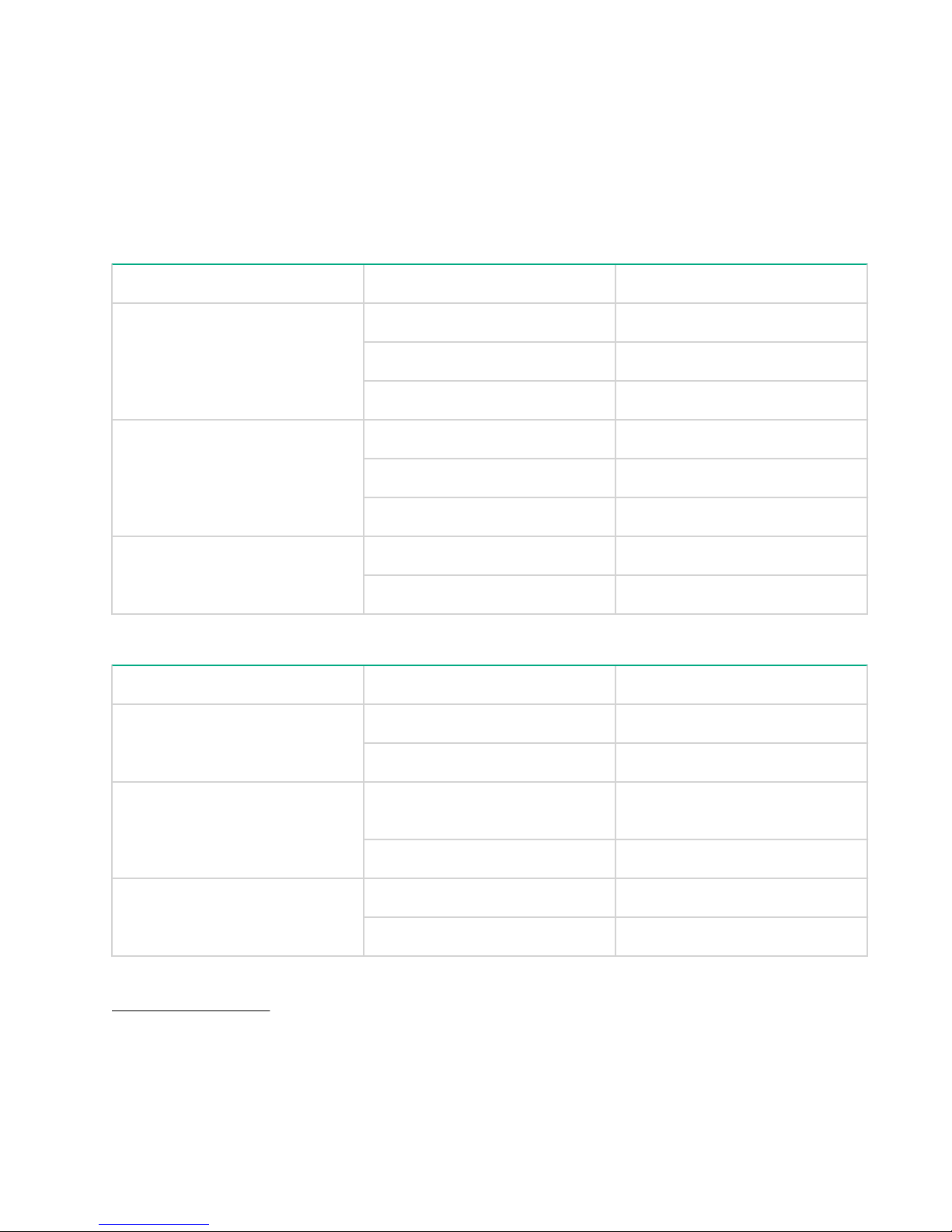
Table 11: Minimum disk drive configuration
Disk type RAID level
LFF
SSD
10K SFF SAS RAID 10 4
7.2K LFF MDL-SAS RAID 10 4
RAID 10 4
RAID 5 6
RAID 6 12
RAID 5 6
RAID 6 12
RAID 6 12
Number of disk drives
Table 12: Supported drives in each tier
Tier Drive type Drive size
Tier 0 SFF SSD 12 Gb SAS 400 GB, 800 GB, 1.6 TB, 3.2 TB
Tier 1 SFF 10K 12 Gb SAS 300 GB, 600 GB, 900 GB, 1.2 TB,
Tier 2 SFF 7200 12 Gb MDL-SAS 2 TB
Related tasks
Installing a disk drive on page 53
24 Adding storage system capacity
LFF SSD 12 Gb SAS 400 GB, 800 GB
1.8 TB
SFF 15K 12 Gb SAS 300 GB, 600 GB
LFF 7.2K 12 Gb MDL-SAS 2 TB, 4 TB, 6 TB, 8 TB
Page 25
Adding a drive enclosure
Installing the rail kits
Procedure
1. Identify the rack locations for the enclosures.
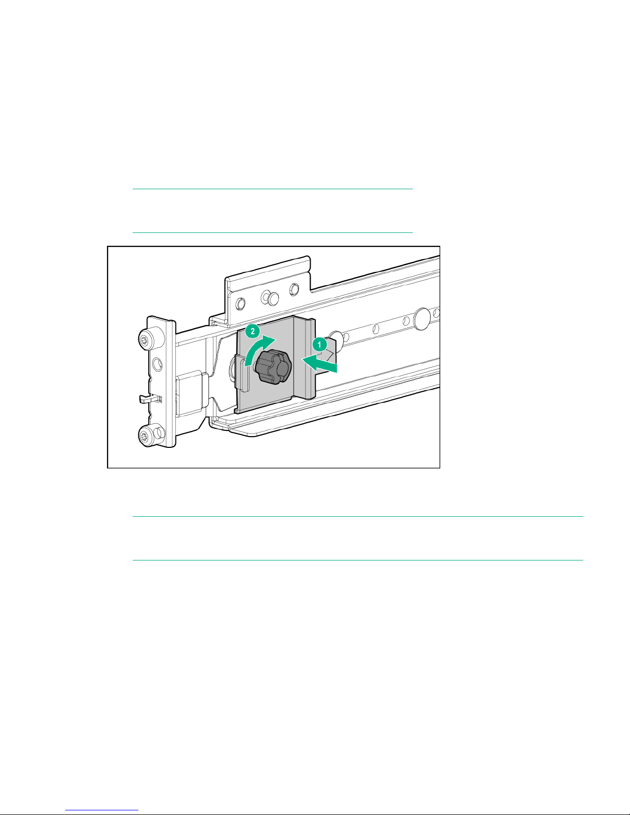
2. Loosen the back bracket on the standard rail kit to accommodate the enclosure. Attach the rear hold down
brackets by sliding the tab with the arrow pointed forward (1) into the corresponding slot on the left and
right side of the rear of the chassis. Use the black headed thumb screw to loosely secure the rail in the
second hole from the rear (2).
NOTE:
It is easier to make this adjustment prior to mounting the rails.
3. Position the left and right rack rails at the desired 'U' position in the rack, adjusting the rails to fit the rack,
as needed. The front and rear bottom edges of the rails must align with the bottom of the EIA boundary in
the lowermost 'U'.
NOTE:
Rails are marked L and R with an arrow indicating the direction in which the rail should be installed.
4. Use guide pins to align the shelf mount kit to the EIA column holes.
5. To engage the rail to the rear of the rack, push the rail toward the back of the rack until the spring hook
snaps into place.
Adding a drive enclosure 25
Page 26
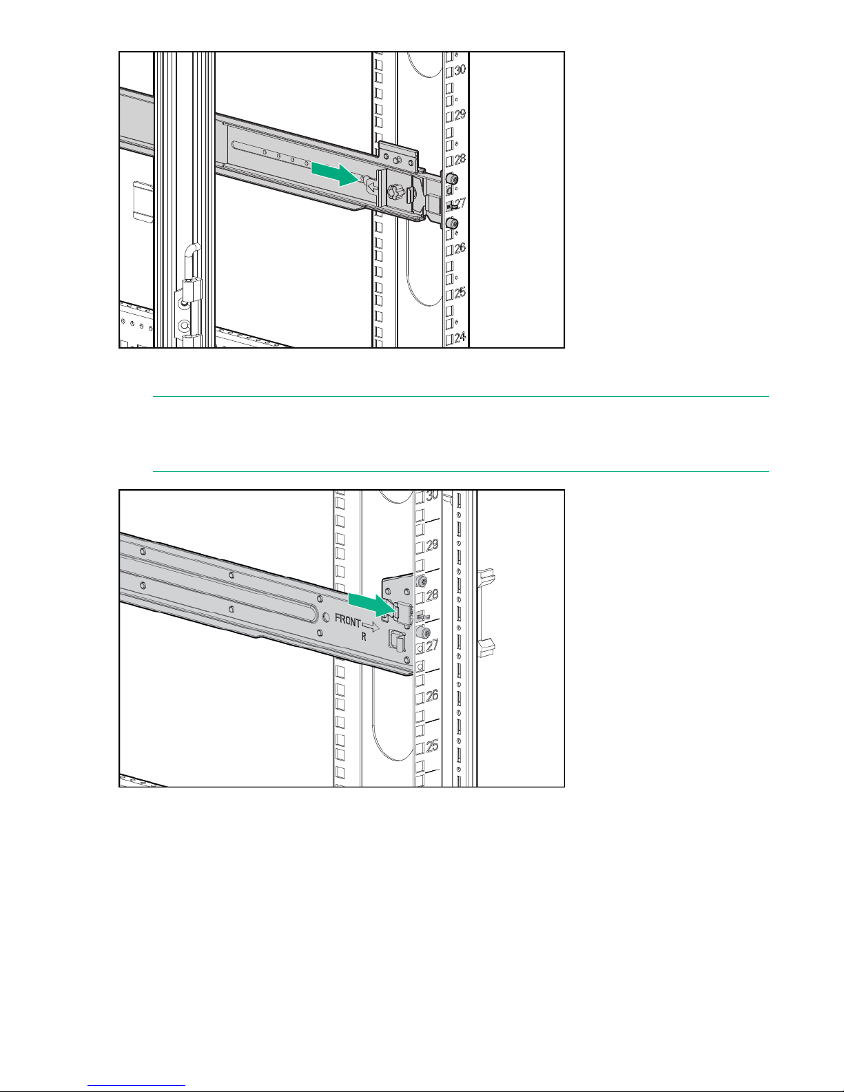
6. To engage the rail to the front of the rack, pull the rail towards the front of the rack until the spring hook
snaps into place.
NOTE:
Make sure that the respective guide pins for the square or round hole rack align properly into the EIA
column hole spacing.
7. Secure the rear of the rack rail to the EIA column with either the round -or square-hole shoulder screws
provided in the package.
26 Adding storage system capacity
Page 27
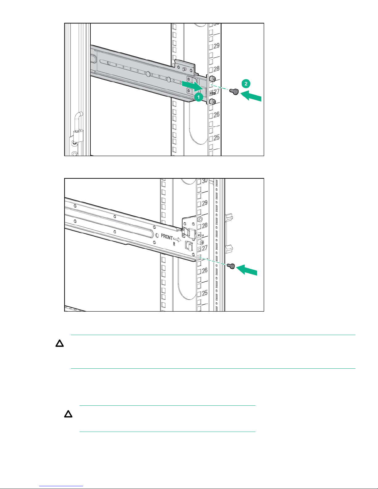
8. Secure the front of the rail to the front EIA column using the flat securing screw/guide pin (provided in the
package) in the bottom screw position of the rail.
Installing the enclosure
CAUTION:
Install disk drives in the enclosure only after mounting the enclosure in the rack. An enclosure with disk
drives installed is too heavy to lift safely.
Procedure
1. Slide the enclosure into position on the rails (1). Secure the chassis into the rack by tightening the captive
CTO screw (3) behind the latch on the front left and right bezel ears of the chassis (2).
CAUTION:
The front CTO screw must be attached at all times when racked.
Installing the enclosure 27
Page 28
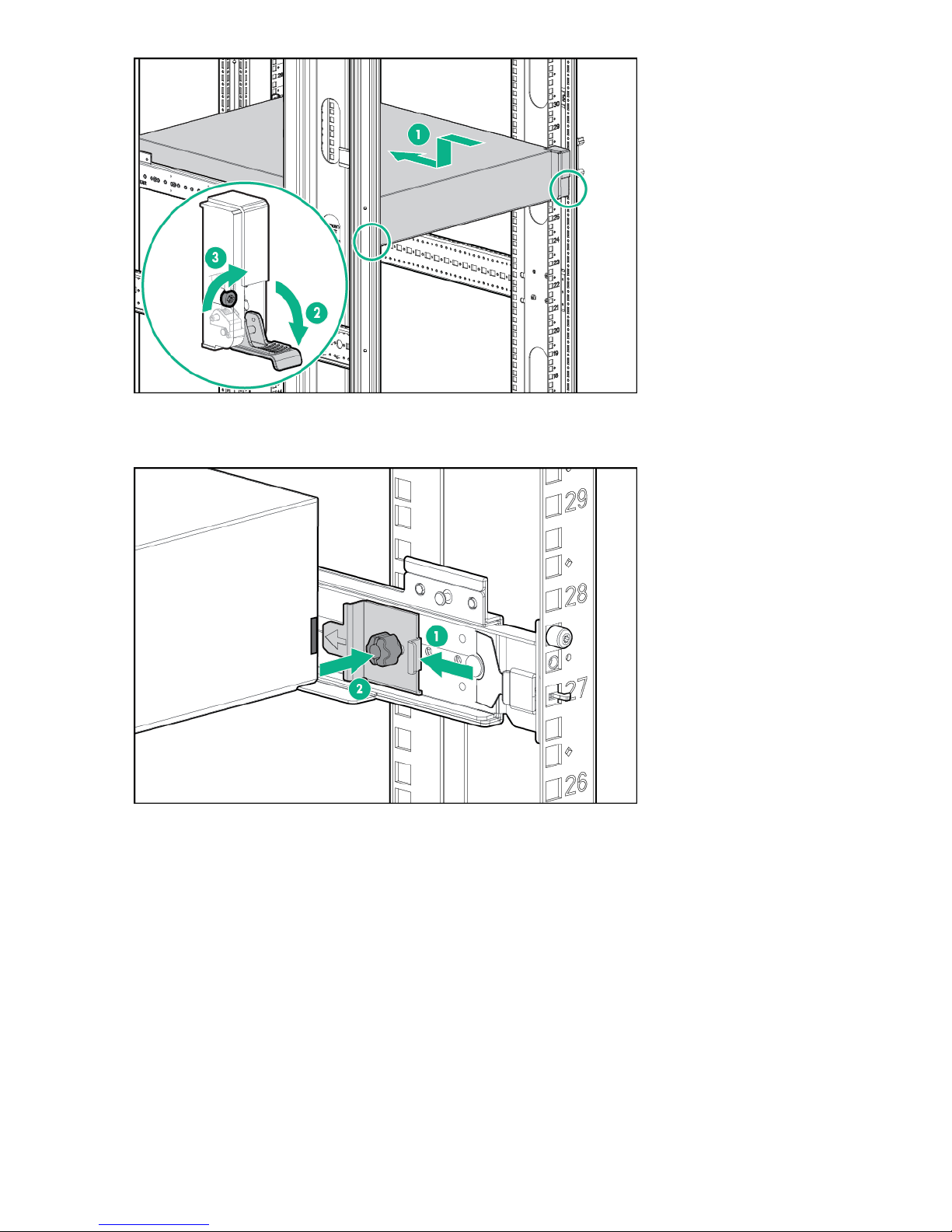
2. Attach the rear, hold down brackets by sliding the tab with the arrow pointed forward (1) into the
corresponding slot on the left and right side of the rear of the chassis. Use the black headed thumb screw
to secure tightly to the rail (2).
Adding StoreVirtual 3200 storage systems
Adding StoreVirtual 3200 storage systems increases the available storage capacity and provides additional
redundancy and reliability. Adding a new StoreVirtual 3200 storage system is limited to iSCSI configurations.
Adding a new storage system to an existing configuration
Prerequisites
• The new storage system must be configured the same as the storage system in the existing management
group and storage pool.
• The new storage system must not be configured in a management group. Stop the Configuration Setup
process after you configure the network settings.
28 Adding StoreVirtual 3200 storage systems
Page 29

Procedure
1. Install the new storage system following the instructions in the HPE StoreVirtual Storage System
2. Use the Configuration Setup to configure the storage system through the Network Configuration step.
3. In the Continue Configuration window, click No
4. Point the web browser to the management IP address that was assigned to one of the storage controllers
5. Log in to the storage system with the User Name and Password admin, admin. These credentials are
6. On the StoreVirtual menu, select Settings
7. Select General and then selectActions > Add storage systems on the content pane.
8. Select a storage system to add to the management group, and click OK.
9. Use the StoreVirtual Management Console to select storage system B to join the same management
10. Follow the instructions in the StoreVirtual Management Console online help to add the storage system to
Installation Guide.
during the network setup.
always used when a storage system is not in a management group.
Use Add IP address and Discover available systems as needed to discover storage systems on the
network.
group as storage system A. From Settings > General view, select Add a storage system from the
Actions menu.
an existing storage pool.
Adding storage system capacity 29
Page 30

HPE StoreVirtual Multi-Site SAN design
The Multi-Site SAN feature enables you to mirror data synchronously between logical or physical sites
automatically. You create a Multi-Site SAN by configuring equal numbers of storage systems to create
isolated failure domains. You creat a MULti-SITE SAN by configuring equal numbers of storage controllers
into sites.
Sites for a Multi-Site SAN can be geographically disparate, such as a primary data site and a back-up site in
another building or on another campus. Sites can exist within the same building on different floors or in
different labs on the same floor. Sites can be two different racks in the same server room or even two groups
of storage systems in the same rack.
Multi-Site SAN features
Multi-Site allows storage controllers to be divided evenly between different sites.
Multi-Site is supported with StoreVirtual OS 13.5 and later.
The Multi-Site SAN feature enables:
• Multi-Site clusters that span two sites for synchronous data replication.
• Geographical awareness, by designating storage systems as members of a particular site.
• Synchronously replicated (mirrored) data between sites, based on volume data protection level.
• Site information that ensures that data is mirrored between sites for high availability and disaster recovery.
• I/O path optimization by assigning application servers to connect to storage systems located in the same
site (site preferencing), causing local reads with only replicated writes between sites.
• Failover Manager support for automatic failover/failback in a two-site configuration without requiring a
physical storage system in a third site.
• Failover Manager for quorum management if the network connection between two sites becomes
unavailable.
• Failure protection through data replication, site design, and quorum managers. A Multi-Site SAN can
protect against data center failures (power or network outages or a natural disaster) and individual storage
system failures (power or network outages, a system disaster, or a system component failure).
For operation information, see the HPE StoreVirtual Management Console User Guide.
Design considerations for a Multi-Site SAN
• Network design—Good network design is a critical part of configuring a Multi-Site SAN to ensure
reliability, high availability, and performance. Typical Multi-Site SAN configurations comprise two sites for
StoreVirtual 3200 storage and support multiple network designs.
• Data replication level—To protect the data across sites, you must choose a data protection level. The
data protection level must have a number of mirrors that is equal to the number of sites in the
configuration. For example, two site configurations require volumes to use Network RAID 10 to survive a
single site failure.
• Managers and quorum—You must also correctly configure the SAN managers for quorum to ensure that
if a failure occurs the system can be properly recovered. Maintaining quorum can be either an automated
process using a Failover manager or manually recovered by an Administrator using a Virtual Manager.
Designing the network for the Multi-Site SAN
Design best practices
30 HPE StoreVirtual Multi-Site SAN design
Page 31

• Single subnet—Hewlett Packard Enterprise recommends using a single subnet.
• Adequate bandwidth between sites—Plan for the appropriate amount of bandwidth for each storage
system between sites. For instance if each site contains one StoreVirtual 3200 storage system, then you
need at least 100 MB/sec throughput between sites.
• Low round-trip latency—To avoid impacting disk I/O to the application server, the round-trip latency
between the sites must be no more than 2 ms.
• Redundant links—Maintain multiple physical connections (media) between the sites for redundancy.
Configure the network so that a link failure does not prevent communication between sites.
• Assign servers to sites—Avoid high-latency connections by assigning application servers to the site
where the server is located. Application servers assigned to a site connect with iSCSI sessions only to
storage systems in the same site when the storage in that site is available.
• Use the Failover Manager—Unless you have storage systems in three physical sites, use a Failover
Manager. Put the Failover Manager on a third logical site:
◦ On a network that is isolated from the other sites.
◦ Use a different power connection.
NOTE:
The minimum requirement for the Failover Manager is 100 Mbps with 50 ms latency.
Calculating bandwidth
Procedure
1. Multiply by the required MB/s.
2. Convert MB/s into GB/s.
See Recommended bandwidth configurations for the appropriate amount of bandwidth.
Inter-site Bandwidth based on the number of storage
systems at a site
Platform Minimum MB/s per
node
StoreVirtual 3200 100 400 2 ms
Maximum MB/s per
node
Round-trip time (RTT)
Calculating bandwidth 31
Page 32

Managing the network
Introduction
The StoreVirtual 3200 has multiple configurations available, including iSCSI and Fibre Channel transport
types.
The StoreVirtual 3200 is a dual controller array. The two storage controllers communicate with each other
over a private communication path called the StoreVirtual Inter-Communication Link. There are no customerbased management interactions with this path.
You connect to the system using one of the Storage Controllers management interfaces. This management
interface is configured during the initial configuration process and provides a communication path for a client
to attach to the system for all management functionality.
The iSCSI and Fibre Channel data is served by the network interfaces depending on your configuration. You
should configure these interfaces based on your network configuration and needs. For iSCSI data, the
available network interfaces should be bonded to provide optimal performance.
Network cabling configurations
The following network cabling configurations are valid for the Configuration Setup procedure. Before
beginning the Configuration Setup procedure, ensure that you have completed the cabling for your system as
described in the following sections. Also ensure that you have the required IP addresses available. The
Configuration Setup procedure allows data and management traffic on the same subnet only.
Connecting the StoreVirtual 3200 Storage system to the network
The array enclosure can be connected to a network in different ways depending on the desired network
configuration and the controller modules.
The following sections contain network connections for supported storage controller configurations.
Network configuration for array enclosure with 1 GbE controller modules (two
port)
All iSCSI, Remote Copy, and Management traffic are routed through these two ports. The two 1 GbE ports are
bonded together for redundancy and performance during the Configuration Setup procedure.
Physical connections
• Connect 1G-1 and 1G-2 on each controller to a switch (four 1 GbE connections)
Required IP addresses
• Two for the 1 GbE network on Controller 1
• Two for the 1 GbE network on Controller 2
• One for the VIP
• All other interfaces are disabled
Figure 14: Configuration using four 1 GbE ports and one switch on page 33 illustrates the cabling
described.
32 Managing the network
Page 33
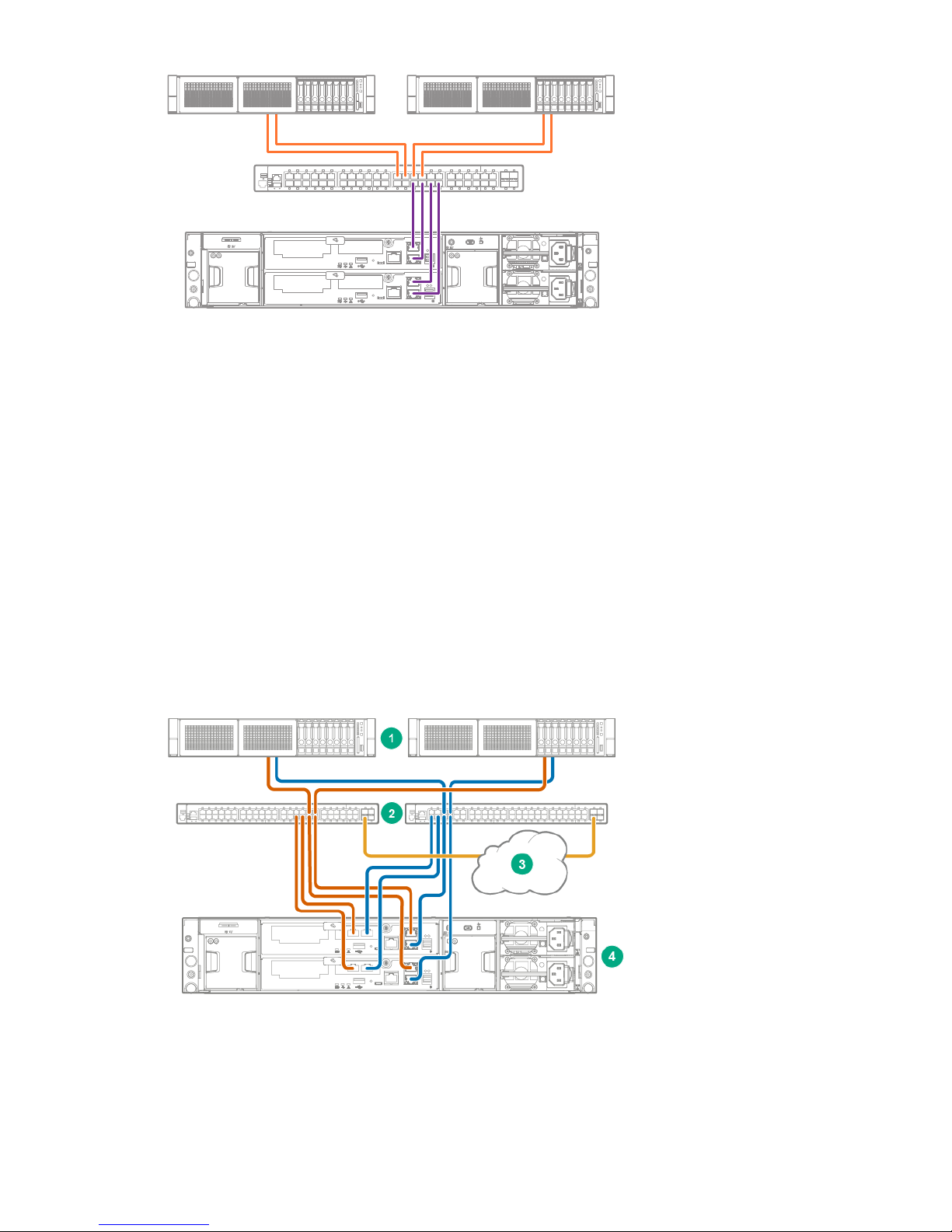
SV3200
Servers
1 GbE iSCSI SAN
Figure 14: Configuration using four 1 GbE ports and one switch
Network configuration for array enclosure with 1 GbE controller modules (four
port)
All iSCSI, Remote Copy, and Management traffic are routed through these four ports. The 1 GbE ports are
bonded together for redundancy and performance during the Configuration Setup procedure.
Physical connections
• Connect 1G-1, 1G-2, 1G-3 and 1G-4 on each controller to a switch (eight 1 GbE connections)
Required IP addresses
• Two for the 1 GbE network on Controller 1
• Two for the 1 GbE network on Controller 2
• One for the VIP
• All other interfaces are disabled
The following figure illustrates the cabling described.
Figure 15: Configuration using four 1 GbE ports and two switches
Network configuration for array enclosure with 1 GbE controller modules (four port) 33
Page 34
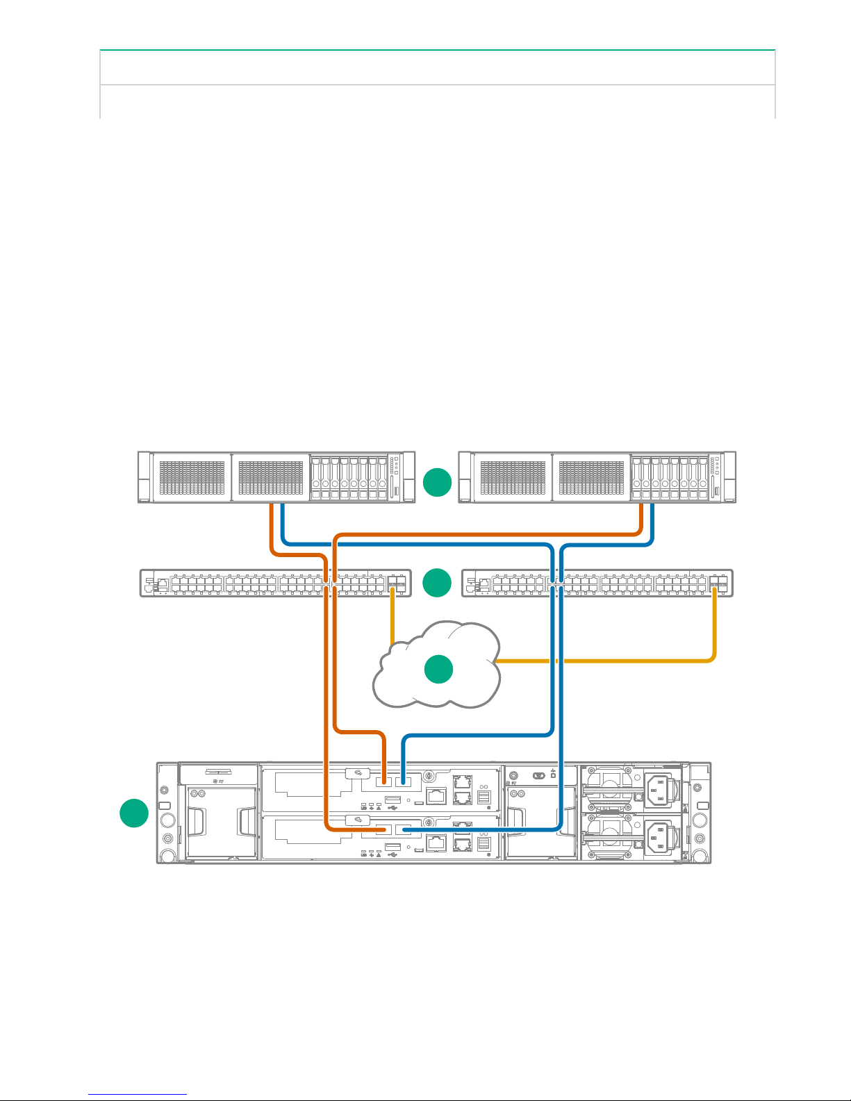
1. Servers 2 . 1 GbE iSCSI SAN
1
2
3
4
3. Cloud connections 4. StoreVirtual storage system
Network configuration for array enclosure with 10 GbE/10GBase-T controller
modules (two port)
All iSCSI, Remote Copy, and Management traffic are routed through these ports. The ports are bonded
together for redundancy and performance during the Configuration Setup procedure.
Physical requirements
• Connect 10G-1 and 10G-2 on each controller to a switch (four 10 GbE connections)
• The two 1 GbE ports must be disabled
IP addresses required
• Two for the 10 GbE/10GBase-T network on Controller 1
• Two for the 10 GbE/10GBase-T network on Controller 2
• One for the VIP
• All other interfaces are disabled
The following figure illustrates the cabling described.
Figure 16: Configuration using four 10 GbE / 10GBase-T ports and two switches
34 Network configuration for array enclosure with 10 GbE/10GBase-T controller modules (two port)
Page 35
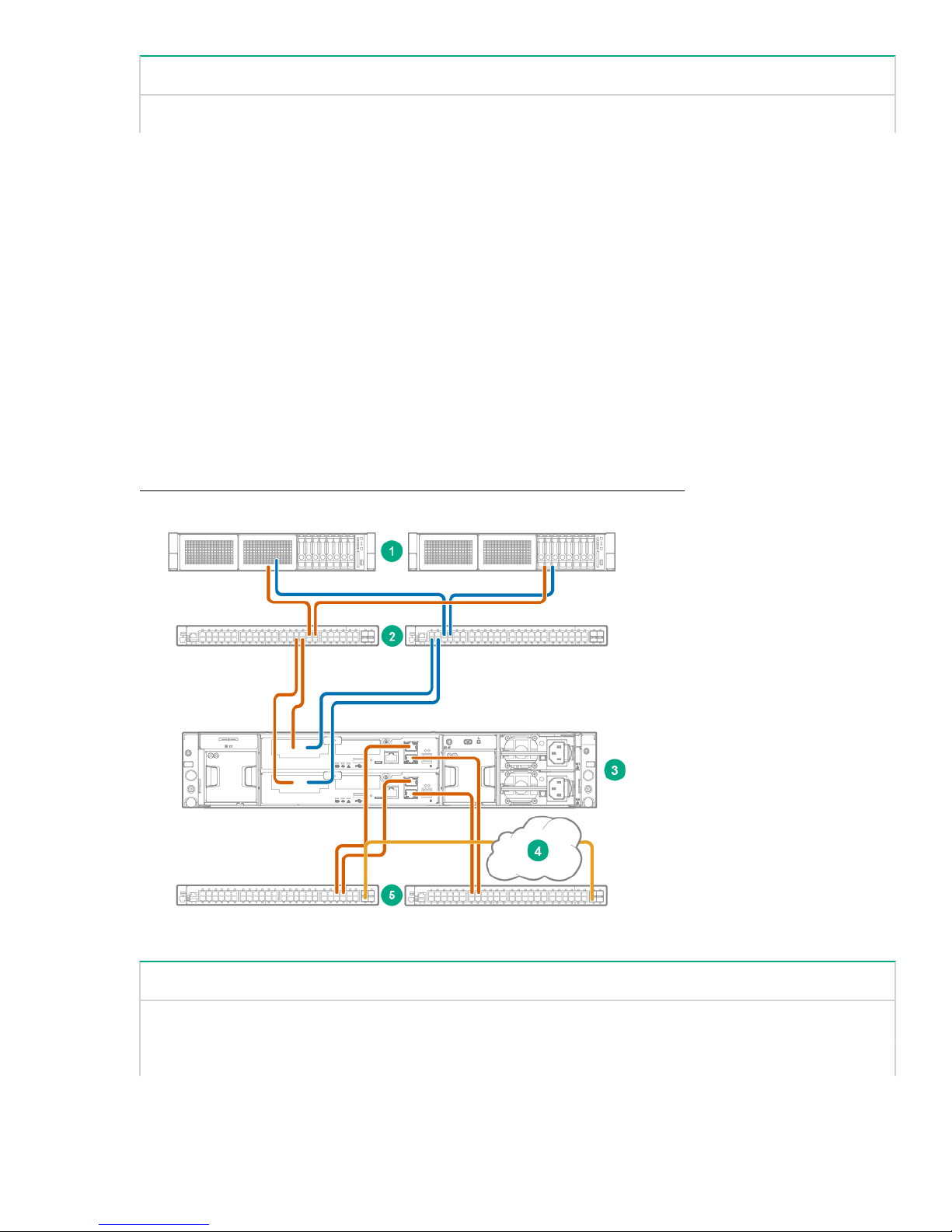
1. Servers 2 . 10 GbE/ 10GBase-T iSCSI SAN
3. Cloud connections 4. StoreVirtual storage system
Network configuration for array enclosure with Fibre Channel controller
modules (two port)
The two Fibre Channel ports on each controller are used for data connections, and the two 1 GbE ports can
be used for Management and Remote Copy. The 1 GbE ports are bonded together for redundancy and
performance during the Configuration Setup procedure.
Physical connections
• Connect FC-1 and FC-2 on each controller to a switch (four Fibre Channel connections)
• Connect 1G-1 and 1G-2 on each controller to a switch (four 1 GbE connections)
Required IP addresses
• One for the 1 GbE network on Controller 1
• One for the 1 GbE network on Controller 2
• One for the VIP (Best Practice)
• All other interfaces are disabled
Figure 17: Configuration using four Fibre Channel ports and two switches on page 35 illustrates the
cabling described.
Figure 17: Configuration using four Fibre Channel ports and two switches
1. Servers 2. Fibre Channel SAN
3. StoreVirtual storage system 4. Cloud connections
5. 1 GbE iSCSI SAN
Network configuration for array enclosure with Fibre Channel controller modules (two port) 35
Page 36
Connecting the StoreVirtual 3000 drive enclosure
1
2
1
2
3
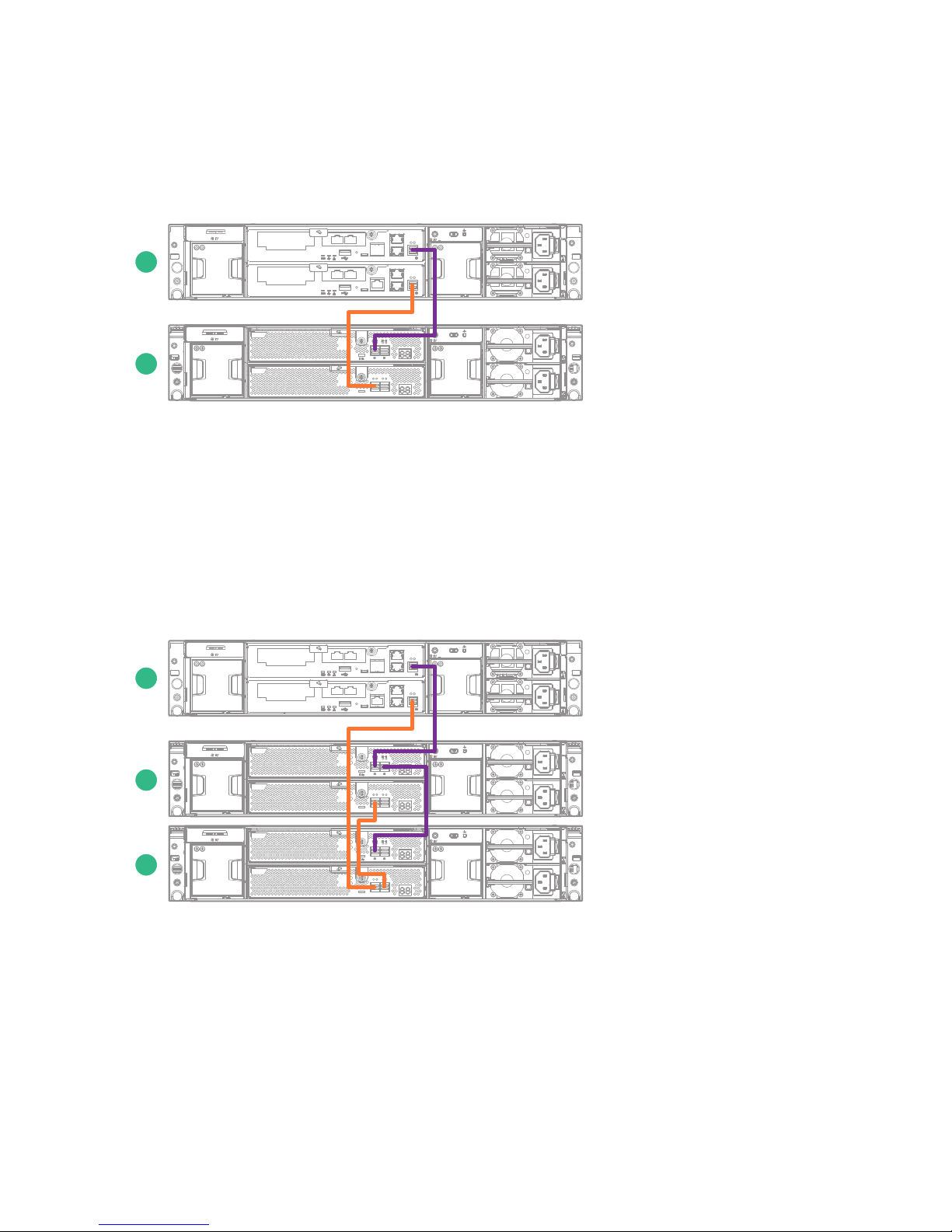
Up to three HPE StoreVirtual 3000 drive enclosures can be connected to the array enclosure. The drive
enclosures must be connected to the array enclosure using an asymmetric cabling scheme as shown in the
following figures. The storage controllers must connect directly to the drive enclosure I/O modules.
Connecting to one drive enclosure
Figure 18: One drive enclosure cabling configuration
1. Array enclosure 2. Drive enclosure
1. Connect DP-1 on the storage controller in slot 1 to DP-1 on the I/O module in slot 1 of the drive enclosure.
2. Connect DP-1 on the storage controller in slot 2 to DP-1 on the I/O module in slot 2 of the drive enclosure.
Connecting to two drive enclosures
Figure 19: Two drive enclosure cabling configuration
1. Array enclosure 3. Drive enclosure 2
2. Drive enclosure 1
36 Connecting the StoreVirtual 3000 drive enclosure
Page 37
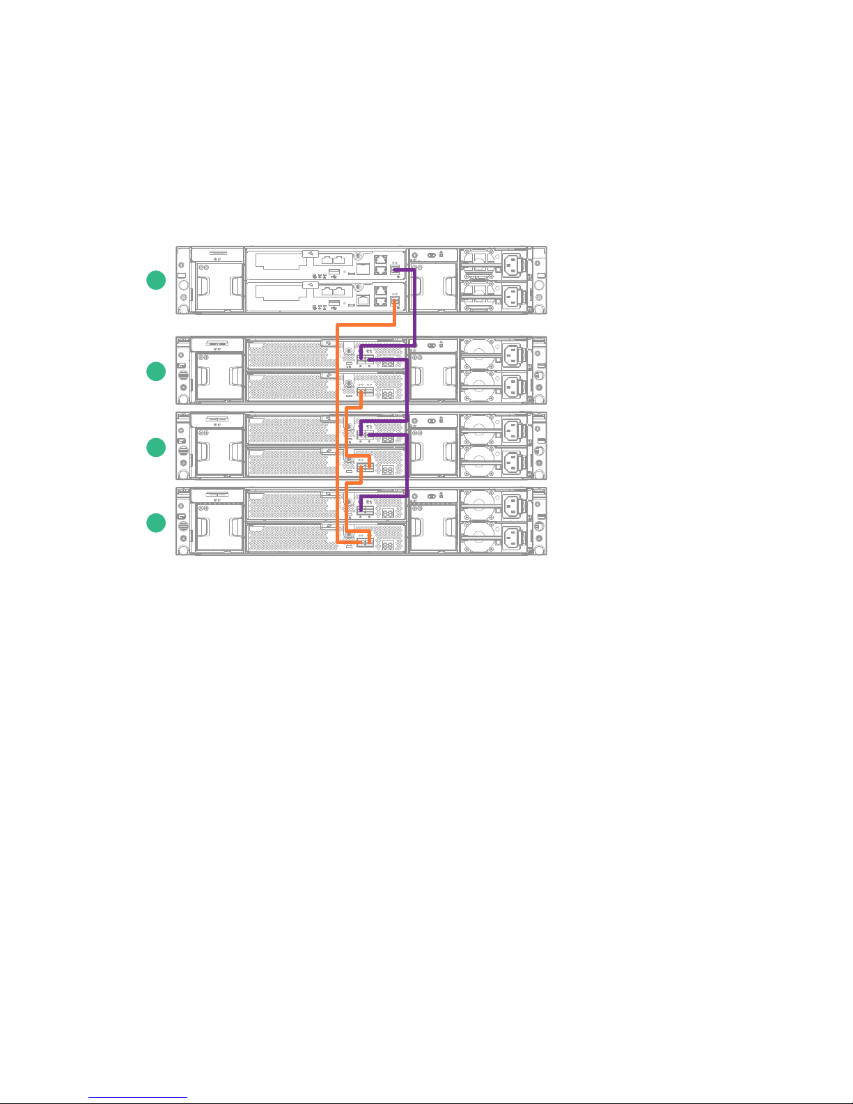
1. Connect DP-1 on the storage controller in slot 1 to DP-1 on the I/O module in slot 1 of the first drive
1
2
3
4
enclosure.
2. Connect DP-2 on the I/O module in slot 1 of the first drive enclosure to DP-1 on the I/O module in slot 1 of
the second drive enclosure.
3. Connect DP-1 on the storage controller in slot 2 to DP-1 on the I/O module in slot 2 of the second drive
enclosure.
4. Connect DP-2 on the I/O module in slot 2 of the second drive enclosure to DP-1 on the I/O module in slot 2
of the first drive enclosure.
Connecting to three drive enclosures
Figure 20: Three drive enclosure cabling configuration
1. Array enclosure 3. Drive enclosure 2
2. Drive enclosure 1 4. Drive enclosure 3
1. Connect DP-1 on the storage controller in slot 1 to DP-1 on the I/O module in slot 1 of the first drive
enclosure.
2. Connect DP-2 on the I/O module in slot 1 of the first drive enclosure to DP-1 on the I/O module in slot 1 of
the second drive enclosure.
3. Connect DP-2 on the I/O module in slot 1 of the second drive enclosure to DP-1 on the I/O module in slot 1
of the third drive enclosure.
4. Connect DP-1 on the storage controller in slot 2 to DP-1 on the I/O module in slot 2 of the third drive
enclosure.
5. Connect DP-2 on the I/O module in slot 2 of the third drive enclosure to DP-1 on the I/O module in slot 2 of
the second drive enclosure.
6. Connect DP-2 on the I/O module in slot 2 of the second drive enclosure to DP-1 on the I/O module in slot 2
of the first drive enclosure.
Bonded interface configuration
In an HPE StoreVirtual 3200 Storage System, the 1GbE and 10GbE/10GBase-T interfaces on both iSCSI and
Fibre Channel Ethernet networks must be configured using bonded interfaces.
Connecting to three drive enclosures 37
Page 38
Using bonded interfaces provides the following benefits:
• Helps prevent routing issues.
• Distributes the outbound network traffic across all of the physical interfaces.
When planning your network configuration, consider the following to ensure that bonding will be set up
correctly:
• All physical interfaces on the same controller and subnet must be bonded to create a single logical
interface.
• Only interfaces on the same controller are bonded. There is no bonding between controllers.
• Bonds can be created between two or four interfaces that have the same speed. There is a maximum of
two 10GbE/10GBase-T interfaces or four 1GbE interfaces in the same bond.
• A bonded interface requires a static IP address; you cannot use a DHCP address.
• When the bond is broken, the IP address used for the bond cannot be on the same physical interface as
the DHCP reservation.
• Symmetric ports of the same type can share a subnet mask across Controllers 1 and 2.
Information needed for Configuration Setup
Configuration Setup includes setting up bonded interfaces. Collect the following information and have it
available when you begin the process.
• Bond type
• For each controller, static IP addresses that are available on the network: two for iSCSI, one for Fibre
Channel per bond
• Subnet mask
Bond types
The following types of bonding are supported with the HPE StoreVirtual 3200 Storage System:
• ALB (default) – Can only be created between two or four interfaces that have the same speed. No
additional network switch configuration is required. There can be a maximum of two 10GbE/10GBase-T
interfaces or four 1GbE interfaces in the same bond.
• Active-Passive – Can only be created between two or four interfaces that have the same speed. The
system supports two 10GbE/10GBase-T interfaces in a bond and two 1GbE interfaces in a bond. No
additional network switch configuration is required.
• 802.3ad – Can only be created between two or more interfaces that have the same speed. All of the
network switches involved with the 802.3ad bond must have the bonded ports connected to the same
backplane. More network switch configuration is required. The system supports a maximum of two 10GbE/
10GBase-T interfaces or four 1GbE interfaces in the same bond.
Bonded interfaces for supported controller configurations
The following sections illustrate bonding set up for each supported controller configuration.
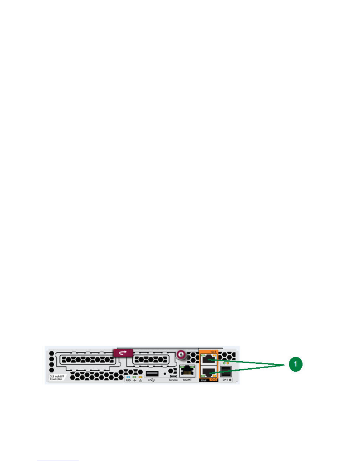
Figure 21: Controller with no option card
38 Managing the network
Page 39
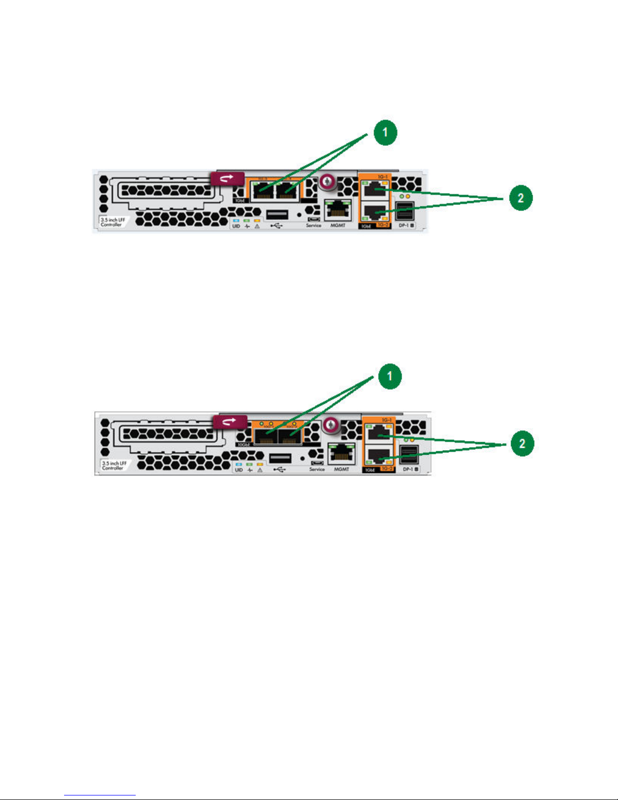
1. Built-in 1G ports
The two built-in 1G ports are bonded and share one subnet mask.
Controller with a 1G GbE card
1. Option card 1G ports
2. Built-in 1G ports
All four 1G ports are bonded and share one subnet mask.
Controller with a 10GbE card
1. Option card 10GbE ports
2. Built-in 1G ports
The 10GbE ports are bonded and share a subnet mask. The built-in 1G ports are in a different bond. The
10GbE and built-in 1G ports must be on different subnets, but they can be used simultaneously.
Managing the network 39
Page 40
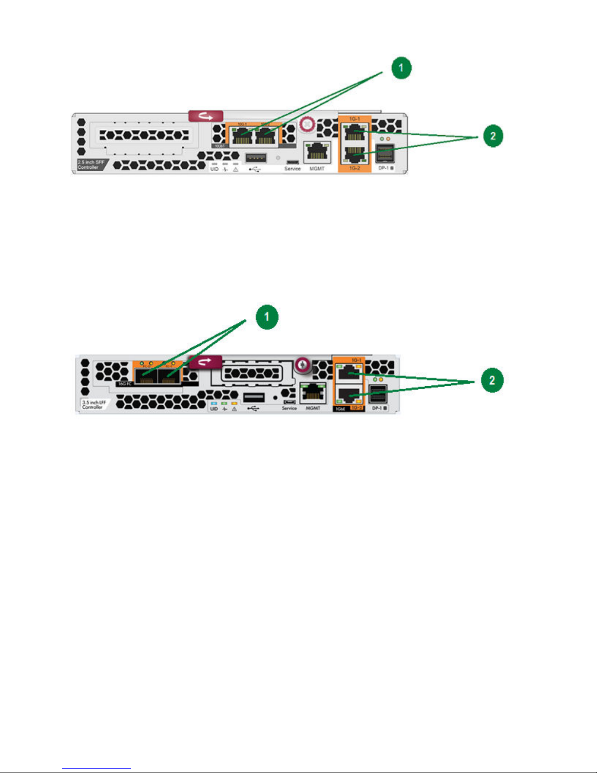
Controller with a 10GBase-T card
1. Option card 10GBase-T ports
2. Built-in 1G ports
The 10GBase-T ports are bonded and share a subnet mask. The built-in 1G ports are not bonded. The
10GBase-T and built-in 1G ports cannot be used simultaneously.
Controller with a Fibre Channel card
1. Option card Fibre Channel ports
2. Built-in 1G ports
The built-in 1G ports are bonded and share a subnet mask. Fibre Channel ports do not require IP addresses,
so no bonding is necessary.
Multipathing with iSCSI configurations
The system can use either a OS-level multipathing driver or a driver provided by a vendor such as a Windows
multipath driver (DSM) or a VMware multipath driver (MEM).
The iSCSI configuration uses MLTP which provides multiple LUNs on a single target.
iSCSI multipathing with DSM or MEM
• Access the SVMC to configure StoreVirtual networking. See the StoreVirtual Management Console Online
Help for more information.
• Requires installation of a a vendor-supplied multipathing driver
• Each controller has a pair of physical network interfaces that are bonded together.
• Two IP addresses are assigned to the bond for optimal performance.
40 Multipathing with iSCSI configurations
Page 41

• A total of four or eight IP addresses can be defined depending upon the number of ports.
• A virtual IP address is configured.
• The client must be enabled with multipathing so that it knows that the same disk is accessible from
multiple paths.
• An iSCSI session from each initiator IP to the virtual IP address used by the StoreVirtual storage system
must be created.
iSCSI multipathing without DSM or MEM
• Access the SVMC to configure StoreVirtual networking. See the StoreVirtual Management Console Online
Help for more information.
Each controller has a pair of physical network interfaces that are bonded together.
• Two IP addresses are assigned to the bond for optimal performance.
• A total of four or eight IP addresses can be defined depending upon the number of ports.
• A virtual IP address can be configured.
• The client must be enabled with multipathing so that it knows that the same disk is accessible from
multiple paths.
• An iSCSI session from each initiator IP to each of the four or eight IPs used by the StoreVirtual storage
system must be created.
iSCSI multipathing without DSM or MEM 41
Page 42
Removing and replacing hardware components
SP# 123456-001 AS# A9B123456
REV: AX
1234ABC6789XYZ
MADE IN XXXXXX
This chapter describes procedures for removing and replacing hardware components. For general information
about customer self repair (CSR), see
Customer self repair (CSR)
Identifying the spare part number
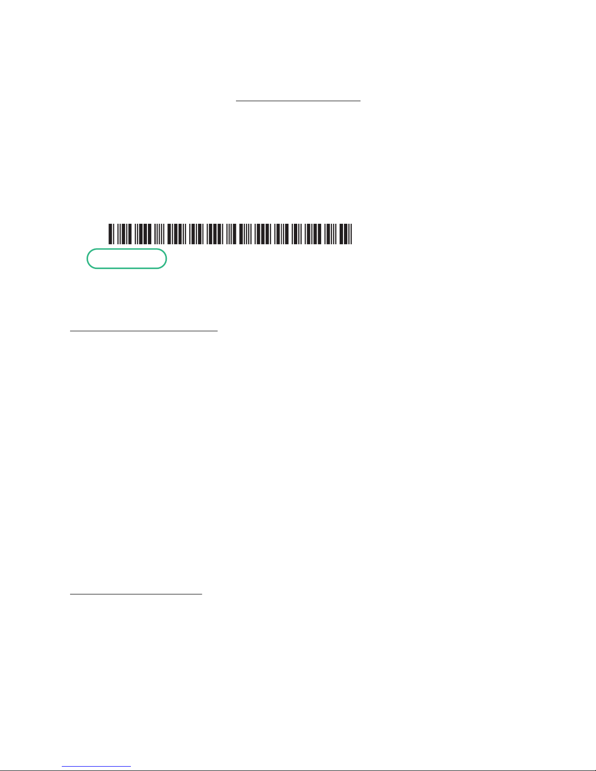
Parts have a nine-character spare part number on their label. If necessary, Hewlett Packard Enterprise
Support can assist in identifying the correct spare part number.
Figure 22: Sample product label
Figure 22: Sample product label on page 42 displays the spare part number shown in green.
Customer self repair (CSR).
Identifying swappable parts
Colored touch points on the part (such as a lever or latch) identify whether the system should be powered on
or off during a part replacement:
• Hot-swappable
parts are identified by red-colored touch points. The system can remain powered on and active during
replacement.
• Warm-swappable
parts are identified by gray-colored touch points. The system will not fail if the part is removed but data
loss may occur if the replacement procedure is not followed correctly.
• Cold-swappable
parts are identified by blue touch points. The system must be powered off or otherwise suspended before
replacing the part.
Accessing component replacement videos
Hewlett Packard Enterprise produced videos of the procedures to assist you in replacing components. To
view the videos, go to the Customer Self Repair Services Media Library website and navigate to your product:
http://www.hpe.com/info/sml
Parts-only warranty service
Your Hewlett Packard Enterprise Limited Warranty may include a parts-only warranty service. Under the
terms of parts-only warranty service, Hewlett Packard Enterprise provides replacement parts, free of charge.
For parts-only warranty service, CSR part replacement is mandatory. If you request Hewlett Packard
Enterprise to replace these parts for you, you are charged for the travel and labor costs of this service.
42 Removing and replacing hardware components
Page 43
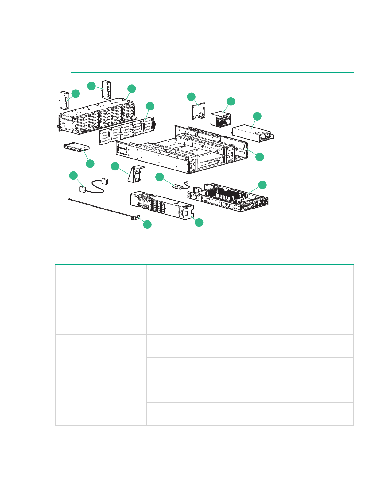
Replaceable parts list
1
2
3
4
5
6
7
8
9
10
11
14
12
15
13
NOTE:
The spare part numbers listed were assigned at initial product release. For the latest updates, go to
HTTP://PARTSURFER.HPE.COM/. Enter your product serial number or model number.
Figure 23: Storage controller enclosure replaceable parts
Table 13: Storage controller enclosure parts list
Callout Description Spare part name Spare part number CSR type
1
2
1 Chassis Bezel
N/A N/A
Ear
2 Chassis Bezel
N/A N/A
Ear
3 Drive Cage SPS Cage; SFF Hard
Disk Drive (HDD)
SPS Cage; LFF Hard
Disk Drive (HDD)
4 Backplane PCA, SFF HDD
781530-001
781531-001
832029-001
Backplane
832030-001
PCA, LFF HDD
Backplane
N/A
2
N/A
2
N/A
2
N/A
Mandatory
Mandatory
Table Continued
Replaceable parts list 43
Page 44

Callout Description Spare part name Spare part number CSR type
1
2
5 Air guard N/A N/A
N/A
6
Power distribution
SPS-VRM Assembly 808276-001
module
7 Power supply SPS-Power Supply
660183-001 Mandatory
750W 1U HEPB
8 Enclosure N/A N/A
9 Controller module SPS Controller Node
840213-001 Mandatory
Assy (SFF/1GbE 2P)
SPS Controller Node
840214-001 Mandatory
Assy (LFF/ 1GbE 2P)
SPS Controller Node
840215-001 Mandatory
Assembly (SFF/ FC)
SPS Controller Node
840216-001 Mandatory
Assembly (LFF/ FC)
SPS Controller Node
840217-001 Mandatory
Assy (SFF/ 1GbE 4P)
SPS Controller Node
840218-001 Mandatory
Assy (LFF/ 1GbE 4P)
N/A
N/A
2
2
SPS Controller Node
840219-001 Mandatory
Assembly(SFF/10GbE)
SPS Controller Node
840220-001 Mandatory
Assembly(LFF/10GbE)
10 Fan module SPS Fan Assembly 781532-001 Mandatory
11
12 Battery SPS-BATT PACK
UID health
module
3
SPS-UID Health
Module
740127-001 Mandatory
759619-001 Mandatory
NiMH 4.3V 8" / 205mm
13
14 Disk drive HPE SV3000 300GB
Intercontroller
link (with bracket)
SPS Intra Controller
Link with bracket
840222-001 Mandatory
832974-001 Mandatory
12G SAS 15K SFF
HDD
Table Continued
44 Removing and replacing hardware components
Page 45

Callout Description Spare part name Spare part number CSR type
1
HPE SV3000 600GB
12G SAS 15K SFF
HDD
HPE SV3000 300GB
12G SAS 10K SFF
HDD
HPE SV3000 600GB
12G SAS 10K SFF
HDD
HPE SV3000 900GB
12G SAS 10K SFF
HDD
HPE SV3000 1.2TB
12G SAS 10K SFF
HDD
HPE SV3000 1.8TB
12G SAS 10K SFF
HDD
832975-001 Mandatory
832969-001 Mandatory
832970-001 Mandatory
832971-001 Mandatory
832972-001 Mandatory
832973-001 Mandatory
HPE SV3000 2TB 12G
SAS 7.2K SFF MDL
HDD
HPE SV3000 2TB 12G
SAS 7.2K LFF MDL
HDD
HPE SV3000 4TB 12G
SAS 7.2K LFF MDL
HDD
HPE SV3000 6TB 12G
SAS 7.2K LFF MDL
HDD
HPE SV3000 8TB 12G
SAS 7.2K LFF MDL
HDD
HPE SV3000 400GB
12G SAS 2.5in MU
SSD
832978-001 Mandatory
832980-001 Mandatory
832976-001 Mandatory
832977-001 Mandatory
832981-001 Mandatory
834291-001 Mandatory
Table Continued
Removing and replacing hardware components 45
Page 46

Callout Description Spare part name Spare part number CSR type
1
HPE SV3000 800GB
12G SAS 2.5in MU
SSD
HPE SV3000 300GB
12G SAS 15K SFF
HDD
HPE SV3000 600GB
12G SAS 15K SFF
HDD
HPE SV3000 400GB
12G SAS 3.5in MU CC
SSD
HPE SV3000 800GB
12G SAS 3.5in MU CC
SSD
HPE SV3000 3.2TB
12G SAS 2.5in MU
SSD
834292-001 Mandatory
832974-001 Mandatory
832975-001 Mandatory
851306-001 Mandatory
851307-001 Mandatory
851305-001 Mandatory
15 Fan control card
cable assembly
16 Drive blank (not
shown)
17 Rail kit (not
shown)
18 CA, EXT, iPASS
x4 HD to HD 3.0,
0.5 (not shown)
19 Transceiver (not
shown)
20 Transceiver (not
shown)
21 Transceiver (not
shown)
SPS - Fan interconnect
740127-001 Mandatory
cable
SPS-BLANK LFF HDD
SPS-HDD BLANK SFF
667279-001
670033-001
Mandatory
Gen8
SPS-RAIL KIT 2U 700520-001 Mandatory
CA, EXT, iPASS x4 HD
717432-001 Mandatory
to HD 3.0, 0.5
16Gb FC SFP
HP 16Gb SFP+ SW 1-
793444-001
793444-001
Mandatory
Mandatory
pack Commercial
XCVR
SPS-SFP+,10G
456096-001 Mandatory
BLc,SR
46 Removing and replacing hardware components
Table Continued
Page 47
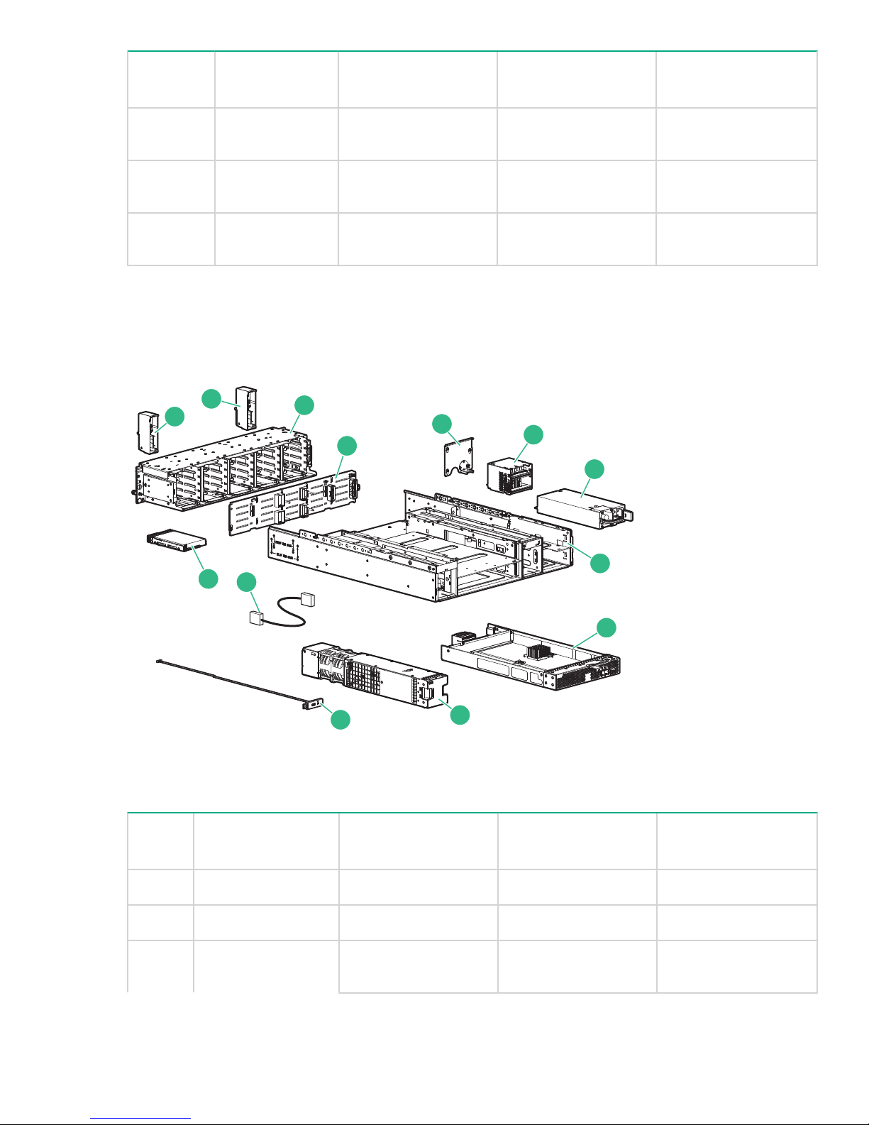
Callout Description Spare part name Spare part number CSR type
1
2
3
4
5
6
7
8
9
10
11
13
12
1
22 Transceiver (not
shown)
23 Transceiver (not
Assy, 10Gb SR SFP +
456096-001 Mandatory
Cable
8Gb FC SFP AJ718-63001 Mandatory
shown)
24 Transceiver (not
shown)
1
Mandatory—You order the part directly from Hewlett Packard Enterprise and repair the product yourself.
8Gb Short Wave FC
SFP+ 1 Pack
AJ718-63001 Mandatory
On-site or return-to-depot repair is not provided under warranty.
2
Not a replaceable spare part .
3
The UID Health Module (Rear Unit ID), Fan Control Card cable assembly, and intercontroller link are
shipped as a single spare replacement.
Figure 24: Drive enclosure replaceable parts
Table 14: Drive enclosure parts list
Callout Description Spare part name Spare part number CSR type
1 Chassis Bezel Ear N/A N/A
2 Chassis Bezel Ear N/A N/A
3 Drive Cage SPS Cage; SFF Hard
Disk Drive (HDD)
781530-001 Mandatory
1
N/A
N/A
2
2
Table Continued
Removing and replacing hardware components 47
Page 48

Callout Description Spare part name Spare part number CSR type
1
SPS Cage; LFF Hard
781531-001 Mandatory
Disk Drive (HDD)
4 Backplane PCA, SFF HDD
832029-001
Backplane
SPS PCA Backplane;
832030-001
LFF HDD
5 Air guard N/A N/A
6 Power distribution
SPS-VRM Assembly 808276-001 Mandatory
module
7 Power supply SPS-POWER SUPPLY,
511777-001 Mandatory
460W
8 Enclosure N/A N/A
9 I/O module SPS I/O Module; SFF 2
781533-001 Mandatory
Port
SPS I/O Module; LFF 2
781867-001 Mandatory
Port
Mandatory
Mandatory
2
N/A
2
N/A
10 Fan module SPS Fan Assembly 781532-001 Mandatory
11 UID health module SPS-UID Health
740127-001 Mandatory
Module
12 Fan control card
cable assembly
13
Disk drive HPE SV3000 8TB 12G
SPS-Fan interconnect
cable
740127–001 Mandatory
832981-001 Mandatory
SAS 7.2K LFF MDL
HDD
HPE SV3000 300GB
832974-001 Mandatory
12G SAS 15K SFF
HDD
HPE SV3000 600GB
832975-001 Mandatory
12G SAS 15K SFF
HDD
HPE SV3000 300GB
832969-001 Mandatory
12G SAS 10K SFF
HDD
Table Continued
48 Removing and replacing hardware components
Page 49

Callout Description Spare part name Spare part number CSR type
1
HPE SV3000 600GB
12G SAS 10K SFF
HDD
HPE SV3000 900GB
12G SAS 10K SFF
HDD
HPE SV3000 1.2TB
12G SAS 10K SFF
HDD
HPE SV3000 1.8TB
12G SAS 10K SFF
HDD
HPE SV3000 2TB 12G
SAS 7.2K SFF MDL
HDD
HPE SV3000 2TB 12G
SAS 7.2K LFF MDL
HDD
832970-001 Mandatory
832971-001 Mandatory
832972-001 Mandatory
832973-001 Mandatory
832978-001 Mandatory
832980-001 Mandatory
HPE SV3000 4TB 12G
SAS 7.2K LFF MDL
HDD
HPE SV3000 6TB 12G
SAS 7.2K LFF MDL
HDD
HPE SV3000 400GB
12G SAS 2.5in MU
SSD
HPE SV3000 800GB
12G SAS 2.5in MU
SSD
HPE SV3000 1.6TB
12G SAS 2.5in MU
SSD
HPE SV3000 300GB
12G SAS 15K SFF
HDD
832976-001 Mandatory
832977-001 Mandatory
834291-001 Mandatory
834292-001 Mandatory
834293-001 Mandatory
832974-001 Mandatory
Table Continued
Removing and replacing hardware components 49
Page 50

Callout Description Spare part name Spare part number CSR type
1
HPE SV3000 600GB
12G SAS 15K SFF
HDD
HPE SV3000 400GB
12G SAS 3.5in MU CC
SSD
HPE SV3000 800GB
12G SAS 3.5in MU CC
SSD
HPE SV3000 3.2TB
12G SAS 2.5in MU
SSD
14 Drive blank (not
shown)
1
Mandatory—You order the part directly from Hewlett Packard Enterprise and repair the product yourself.
On-site or return-to-depot repair is not provided under warranty.
2
Not a replaceable spare part
SPS-BLANK LFF HDD 667279-001 Mandatory
SPS-HDD BLANK SFF
Gen8
832975-001 Mandatory
851306-001 Mandatory
851307-001 Mandatory
851305-001 Mandatory
670033-001 Mandatory
Warnings and precautions
Preventing electrostatic discharge
An electrostatic discharge can damage static-sensitive devices or micro circuitry. Proper packaging and
grounding techniques are necessary precautions to prevent damage. To prevent electrostatic damage,
observe the following precautions:
• Transport products in static-safe containers such as conductive tubes, bags, or boxes.
• Keep electrostatic-sensitive parts in their containers until they arrive at static-free workstations.
• Cover workstations with approved static-dissipating material. Use a wrist strap connected to the work
surface, and properly grounded (earthed) tools and equipment.
• Keep work area free of nonconductive materials, such as ordinary plastic assembly aids and foam
packing.
• Ensure that you are always properly grounded (earthed) when touching a static-sensitive component or
assembly.
• Avoid touching pins, leads, or circuitry.
• Always place drives with the Printed Circuit Board assembly-side down.
• Use conductive field service tools.
50 Warnings and precautions
Page 51
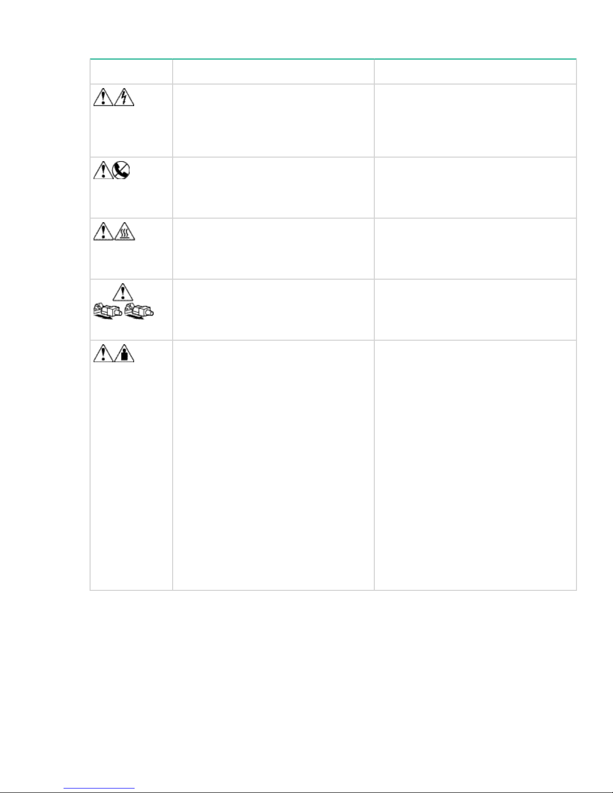
Equipment symbols
Symbol Description Warning
Any enclosed surface or area of the
equipment marked with these symbols
indicates the presence of electrical shock
hazards. Enclosed area contains no
operator serviceable parts.
Any RJ-45 receptacle marked with these
symbols indicates a network interface
connection.
Any surface or area of the equipment
marked with these symbols indicates the
presence of a hot surface or hot
component.
Power supplies or systems marked with
these symbols indicate the presence of
multiple sources of power.
Any product or assembly marked with these
symbols indicates that the component
exceeds the recommended weight for one
individual to handle safely.
To reduce the risk of injury from electrical
shock hazards, do not open this enclosure.
To reduce the risk of electrical shock, fire,
or damage to the equipment, do not plug
telephone or telecommunications
connectors into this receptacle.
Contact with this surface could result in
injury.
To reduce the risk of injury from electric
shock, remove all power cords to
completely disconnect power from the
system.
To reduce the risk of personal injury or
damage to the equipment:
• Remove all hot-pluggable power
supplies and modules to reduce the
overall weight of the device before
lifting.
• Observe local health and safety
requirements and guidelines for manual
material handling.
• Get help to lift and stabilize the device
during installation or removal, especially
when the device is not fastened to the
rails. When a device weighs more than
22.5 kg (50 lb), at least two people must
lift the component into the rack together.
If the component is loaded into the rack
above chest level, a third person must
assist in aligning the rails while the other
two support the device.
Required tools
The following items are required for some replacement procedures:
• Flat-head screwdriver
• T-25 Torx screwdriver
Equipment symbols 51
Page 52
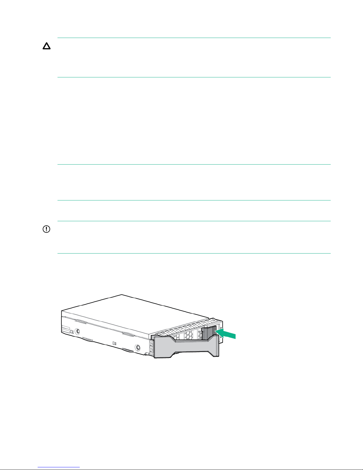
Replacing a disk drive
CAUTION:
To prevent improper cooling and thermal damage, operate the enclosure only when all bays are
populated with either a disk drive or a blank. The enclosure can be operated for the short period of time
required to replace a failed disk drive.
Verifying disk drive failure
Before replacing a disk drive, verify its status using one of the following methods:
Procedure
1. Check the disk drive status LEDs to ensure that the drive has failed. For the location of the disk drive
LEDs, see the Disk drive status LEDs table.
2. Check the disk drive status from the StoreVirtual 3200 Management Console.
Navigate to the Disks section of the StoreVirtual Management Console. The Health tile on the Disks
Overview window displays the disk status.
NOTE:
From the StoreVirtual Management Console, select Locate to turn on the disk UUID blue LED and
ensure that you are replacing the correct disk drive.
Removing a disk drive
IMPORTANT:
Label all disk drives before removing them to ensure that they are reinstalled in the proper enclosure
bays.
Procedure
1. To open the latch handle, press the release button on the disk drive being replaced.
Figure 25: LFF handle release button
52 Replacing a disk drive
Page 53
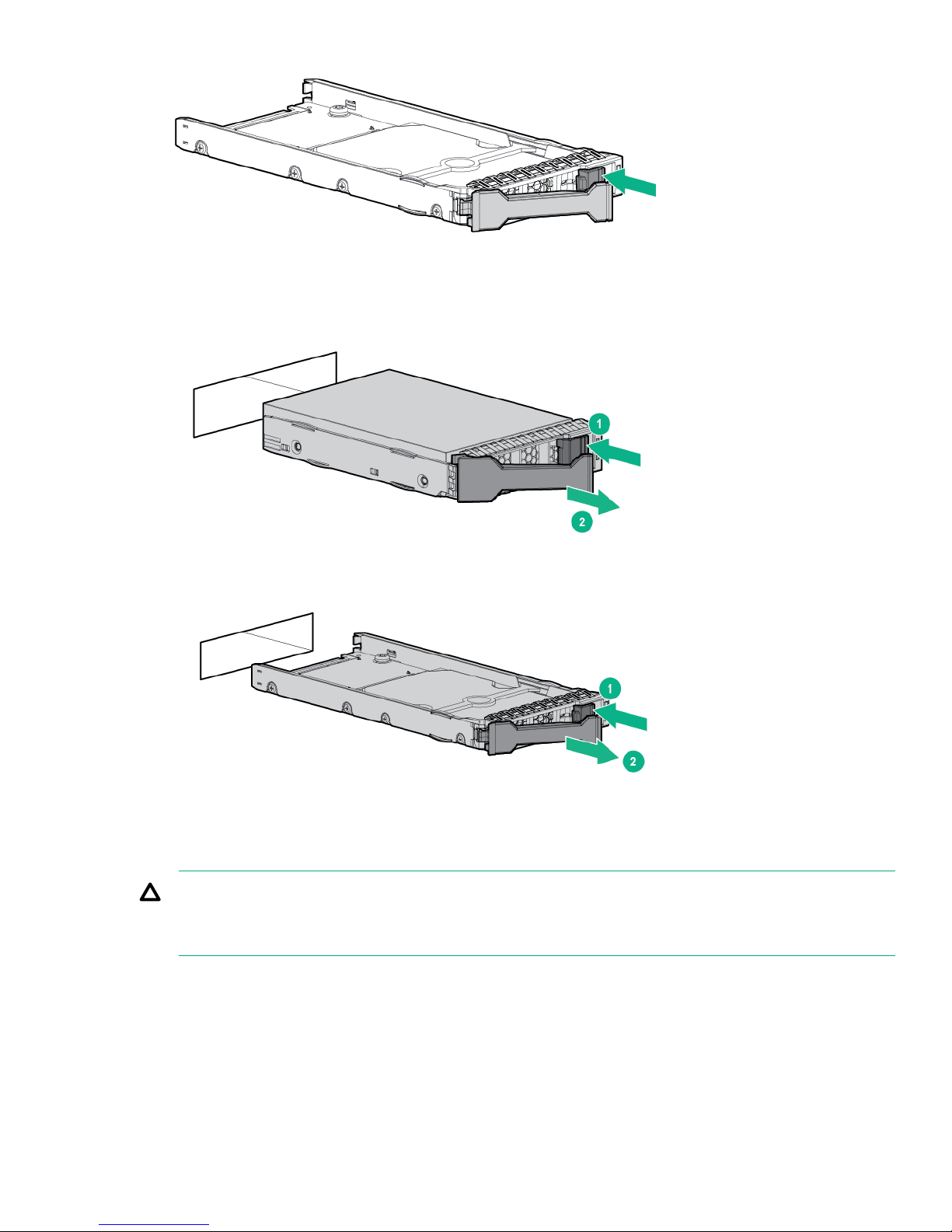
Figure 26: SFF handle release button
2. Swing out the latch handle on the drive (1) and pull the drive out of the enclosure bay (2).
Figure 27: LFF disk drive removal
Figure 28: SFF disk drive removal
Installing a disk drive
CAUTION:
To prevent improper cooling and thermal damage, operate the enclosure only when either a disk drive or
a drive blank is installed in every bay.
Procedure
1. Remove the drive blank.
Installing a disk drive 53
Page 54
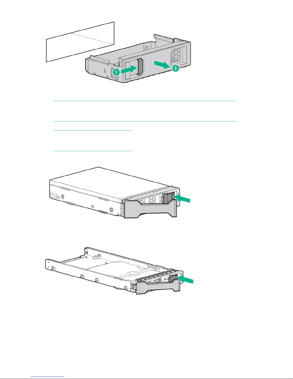
Figure 29: LFF disk drive blank
NOTE:
Removal of an SFF drive blank is similar to the example shown for the LFF drive blank.
2. Unlatch the handle by pressing the button on the disk drive.
NOTE:
Both LFF and SFF disk drives shown.
Figure 30: LFF handle release button
Figure 31: SFF handle release button
3. Swing out the latch handle on the drive. Then, slide the drive into the bay (1), pressing firmly on the drive
to seat it. Close the latch handle (2), pressing firmly until it locks into place.
54 Removing and replacing hardware components
Page 55
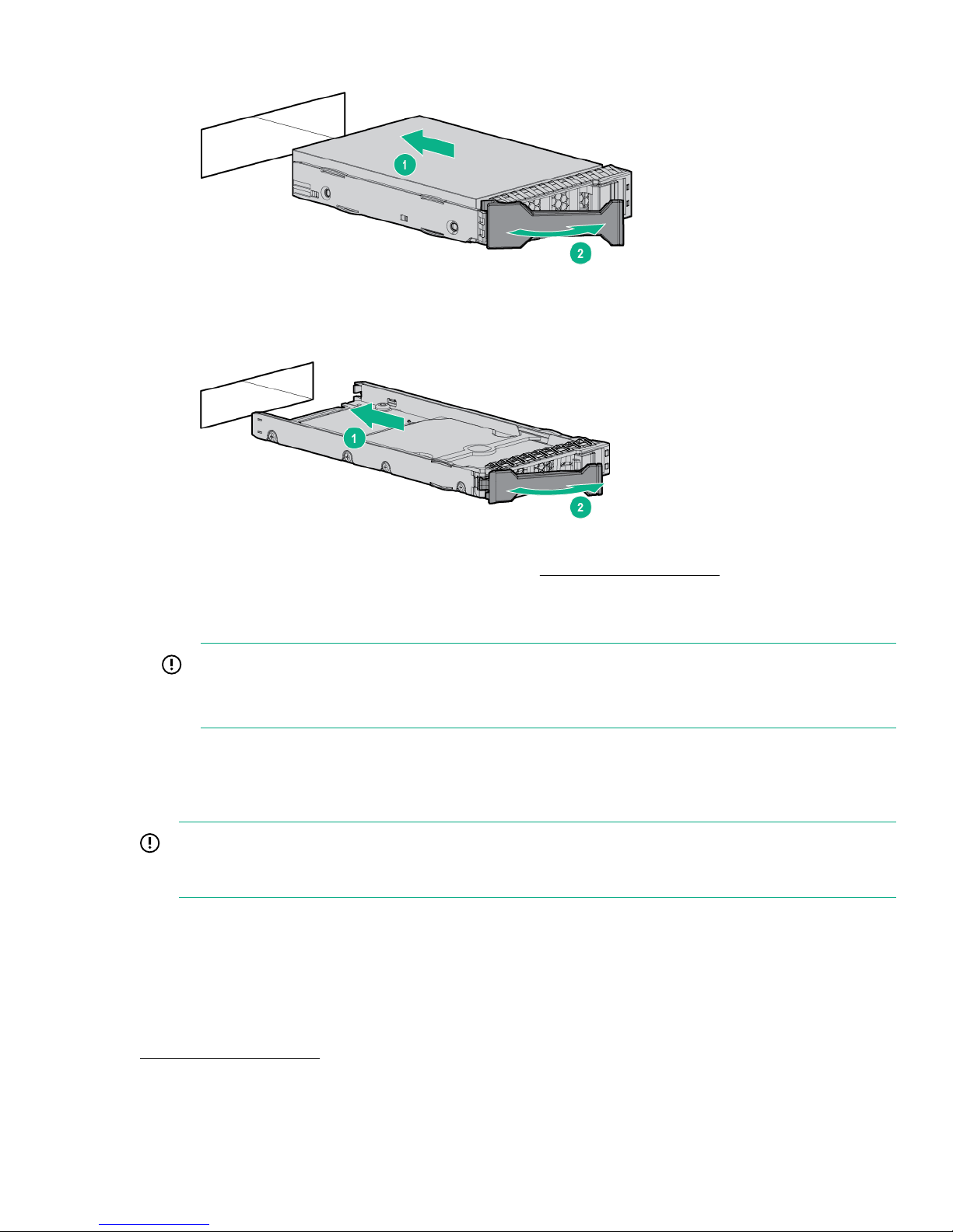
Figure 32: LFF disk drive
Figure 33: SFF disk drive
4. Verify the status of the disk drive. For drive status, see Status LED descriptions.
To view the status using the management software, log on to the StoreVirtual Management Console and
navigate to the Disks section. The Health tile on the Disks Overview window displays the disk status.
IMPORTANT:
When a drive is inserted in an operational enclosure, the drive LEDs flash to indicate that the drive is
seated properly and receiving power.
5. In the StoreVirtual Management Console, select Configure RAID to add the new storage. See the HPE
StoreVirtual Online Help for more information.
Verifying disk drive operation
IMPORTANT:
When a disk drive is inserted in an operational enclosure, the drive LEDs flash to indicate that the drive
is seated properly and receiving power.
• Check the disk drive status LEDs to ensure that the drive is operating properly. For more information, see
"Related reference".
• Check the disk drive status from the StoreVirtual Management Console. Navigate to section of the Disks
StoreVirtual Management Console.
. The Health tile on the Disks Overview window displays the disk status.
Related reference
Status LED descriptions on page 15
Verifying disk drive operation 55
Page 56

Replacing a controller module
Prerequisites
• Verify the status of the controller module.
IMPORTANT:
As soon as you have verified that you must replace the controller, contact Hewlett Packard
Enterprise support. You cannot replace both controllers at the same time. One controller must be
functioning for failover.
• Verify that the volumes and snapshots are not restriping.
• Back up your data.
• Fail over the storage controller from the Storage Systems pane in the StoreVirtual Management Console.
See the HPE StoreVirtual 3200 Online Help for more information.
NOTE:
Ensure that the controller taking over all activities is fully functional. A controller replacement can be
done online, but there is reduced system performance. If performing the replacement online, Hewlett
Packard Enterprise strongly recommends doing so during a time of low activity.
Related reference
Verifying controller module failure on page 56
Verifying controller module failure
Before replacing a controller module, verify its status using one of the following methods:
• Verify using the controller module status LEDs to ensure it has failed. For the location of the controller
module LEDs, see Storage controller enclosure on page 8.
For information on interpreting the status, see "Related reference".
• Verify the controller module status from the StoreVirtual Management Console. Navigate to the Storage
Controllers section. The controller status is listed next to the controller name in the left list pane.
Related reference
Storage controller enclosure on page 8
Storage controller enclosure controller module status LEDs on page 17
Status LED descriptions on page 15
Removing a controller module
Procedure
1. (Optional) If you choose to perform the replacement offline, first shut down the failed controller using the
Recovery/Power button. Then, shut down the other controller.
2. Unplug all cables from the controller module.
a. Do not unplug the power cables if performing a hot or warm swap.
b. If SAS cables are being used to connect enclosures and you must disconnect from the affected
enclosure, be sure that you do not remove both SAS cables at the same time. At least one SAS cable
must be connected to the component to ensure access continues to the drives in the enclosure.
3. Loosen the captive retaining thumbscrew (1) and swing out the controller module handle (2).
56 Replacing a controller module
Page 57
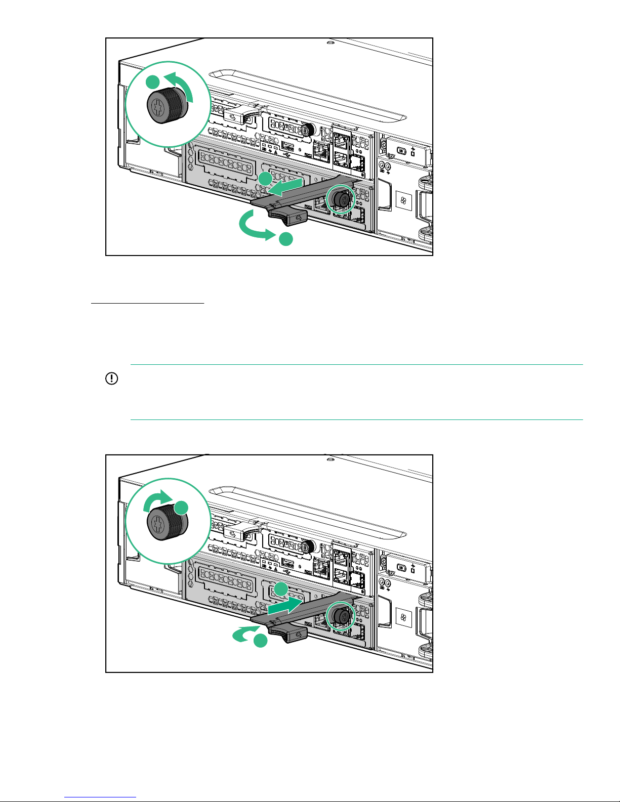
2
1
3
4. Pull the controller module (3) out of the enclosure using the controller module handle.
3
2
1
Related reference
Recovery/Power button on page 12
Installing a controller module
Procedure
1.
IMPORTANT:
Remove the battery from the failed controller. Batteries are not supplied with a replacement
controller.
1. Slide the replacement controller module (1) into the enclosure and close the controller module handle (2).
2. Retighten the captive retainer thumbscrew (3).
3. Reconnect all cables to the controller module.
4. To verify that the controller module is operating properly, check the status LEDs. For more information, see
"Related reference".
Installing a controller module 57
Page 58

Related reference
Storage controller enclosure controller module status LEDs on page 17
Completing the controller module replacement
In the StoreVirtual Management Console:
Procedure
1. Navigate to the Storage Controllers section to verify the controller module status. The controller status is
listed next to the controller name in the left list pane.
2. Use Restore peer to reassociate the two storage controllers. The Restore peer function will be required in
most controller replacements, specifically if the failed controller had completed initial configuration.
NOTE:
If the failed controller has not been configured, the Restore peer function is only required if there is a
version mismatch between the failed controller and the replacement controller.
3. Fail back the storage controller.
NOTE:
You can locate failback in the StoreVirtual Management Console Storage Systems pane.
See the HPE StoreVirtual 3200 Management Console Online Help for more information.
Replacing a drive enclosure I/O module
Verify I/O module failure
Before replacing an I/O module, verify its status using one of the following methods:
• Ensure that the I/O module has failed by verifying the I/O module status LEDs. For the location of the I/O
module LEDs, see HPE StoreVirtual 3000 drive enclosure on page 12. For information on interpreting
the status, see "Related reference".
• Verify the I/O module status from the hardware report in the StoreVirtual Management Console.
Related reference
Status LED descriptions on page 15
Removing an I/O module
Procedure
1. Unplug all cables from the I/O module.
a. Do not unplug the power cables if performing a hot or warm swap.
b. If SAS cables are being used to connect enclosures and you must disconnect from the affected
enclosure, be sure that you do not remove both SAS cables at the same time. At least one SAS cable
must be connected to the component to ensure access continues to the drives in the enclosure.
2. Loosen the captive retaining thumbscrew (1), and swing out the I/O module handle (2).
58 Completing the controller module replacement
Page 59
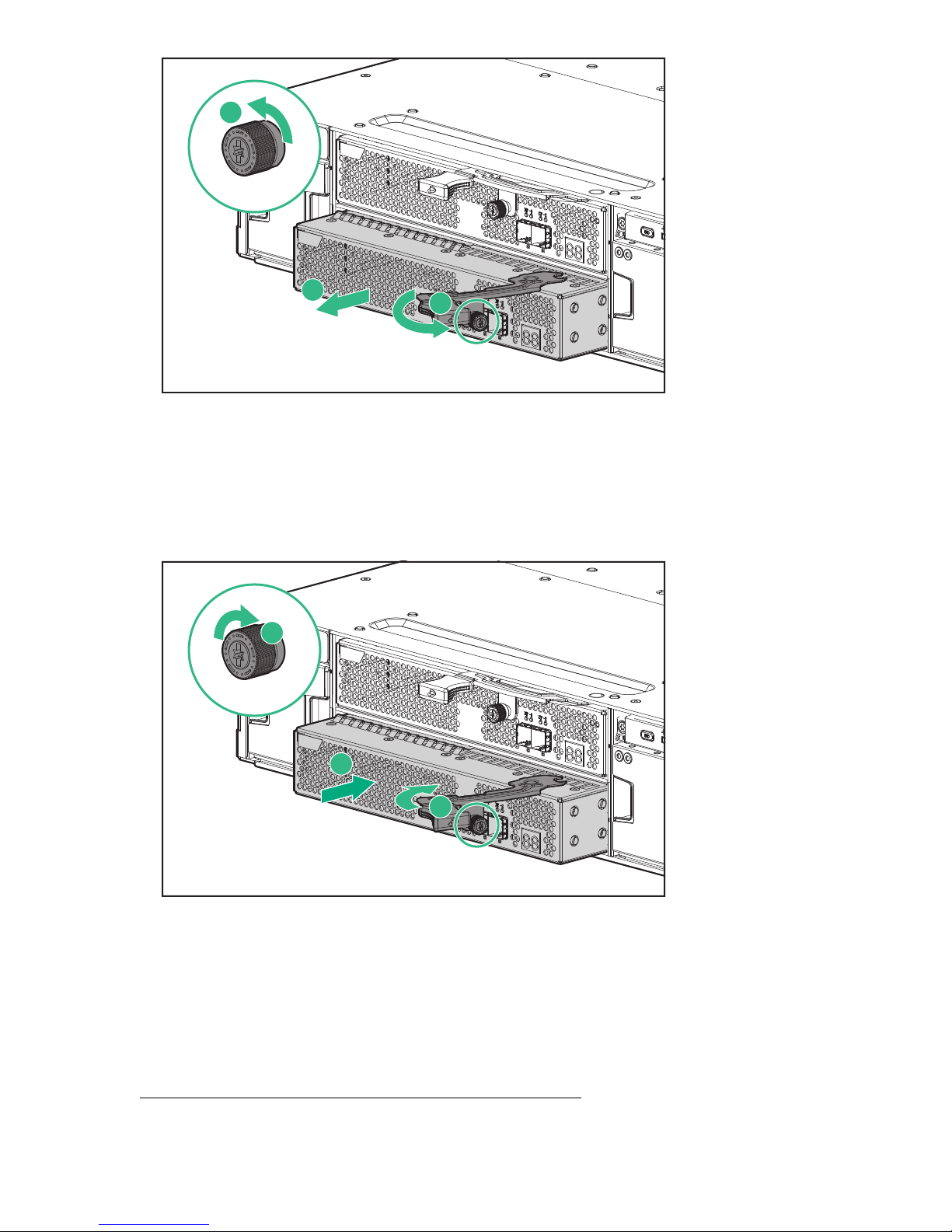
1
2
3
3. Pull the I/O module (3) out of the enclosure using the I/O module handle.
3
2
1
Installing an I/O module
Procedure
1. Slide the replacement I/O module (1) into the enclosure and close the I/O module handle (2).
2. Tighten the captive retainer thumbscrew (3).
3. Reconnect all cables to the I/O module.
Verifying I/O module operation
Procedure
1. Ensure the I/O module is operating properly by checking the status LEDS. For more information, see
"Related reference".
Related reference
Storage controller enclosure controller module status LEDs on page 17
Installing an I/O module 59
Page 60
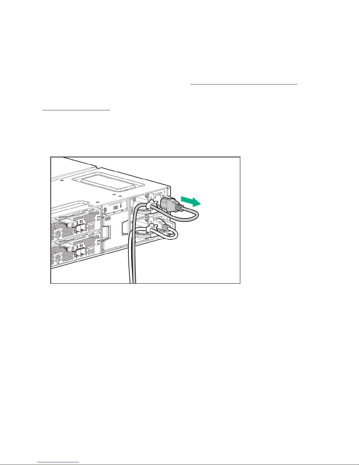
Replacing a power supply module
Verifying power supply failure
Procedure
1. Before replacing a power supply, check the power supply status LED to ensure that the power supply has
failed. For the location of the power supply LEDs, see HPE StoreVirtual 3000 drive enclosure on page
12. For information on interpreting the status, see "Related reference".
Related reference
Status LED descriptions on page 15
Removing a power supply
Procedure
1. Remove the power cable from the power supply to be replaced.
2. Press the latch (1) and slide the power supply module out of the enclosure (2).
60 Replacing a power supply module
Page 61
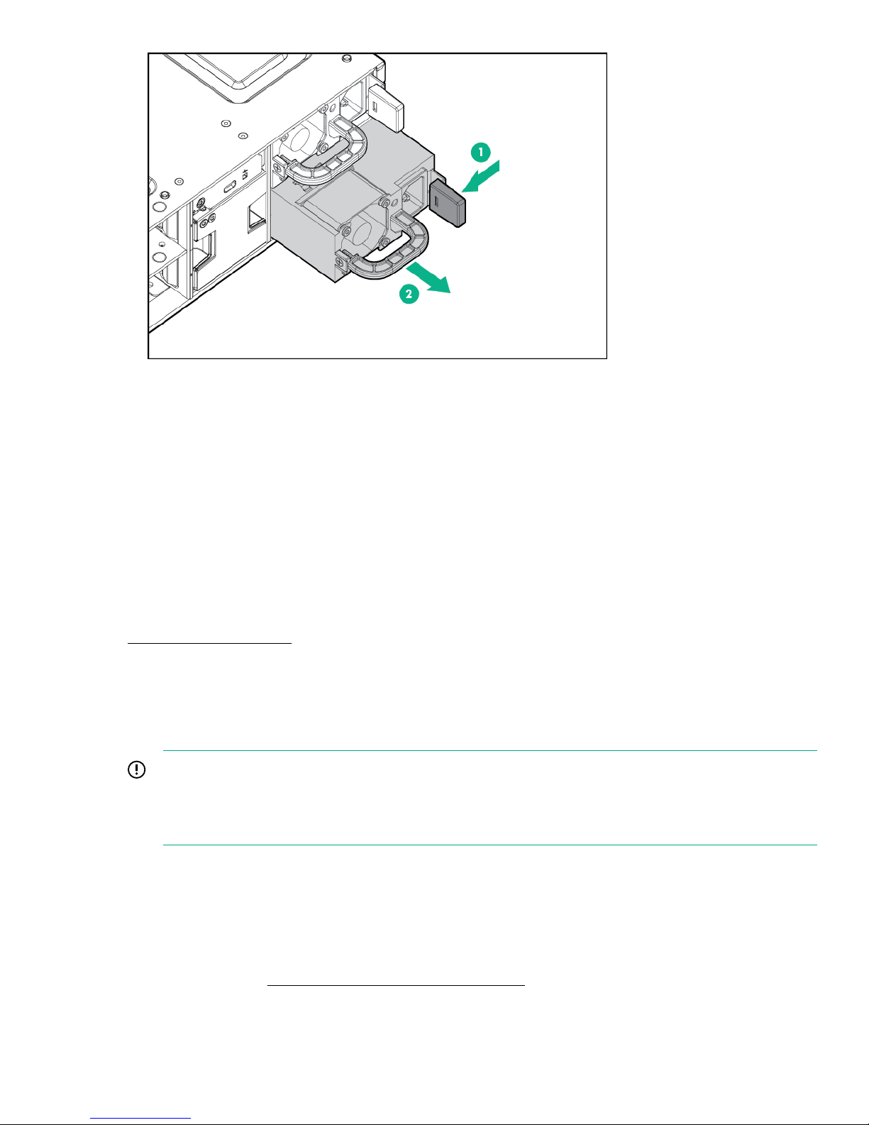
Installing a power supply
Procedure
1. Slide the replacement power supply into the enclosure until it clicks into place.
2. Connect the power cable.
Verifying power supply operation
Procedure
1. Ensure that the power supply is operating properly by checking the status LED. For more information, see
"Related reference".
Related reference
Status LED descriptions on page 15
Replacing a fan module
Before you begin
IMPORTANT:
Make sure that you have the replacement fan module unpacked and available for installation before
removing the failed fan. Ensure proper cooling, because the fan module replacement must be done
within three minutes or the temperature rises.
Verifying fan module failure
Before replacing a fan module, verify its status using one of the following methods:
Procedure
1. Ensure that the fan module has failed by checking the fan module status LEDs. For the location of the fan
module LEDs, see HPE StoreVirtual 3000 drive enclosure on page 12.
Installing a power supply 61
Page 62
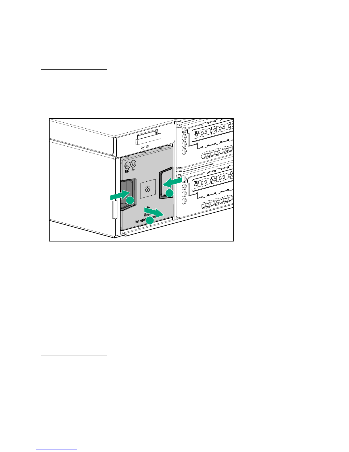
For information on interpreting the status, see "Related reference".
1
1
2
2. Check the fan module heath in the Storage System Hardware Report available from the StoreVirtual
Management Console.
There is also an alert triggered when the fan module fails.
Related reference
Status LED descriptions on page 15
Removing a fan module
Procedure
1. Press in the fan module release buttons (1).
2. Slide the module (2) out of the enclosure.
Installing a fan module
Procedure
1. Slide the replacement fan module into the enclosure until it clicks into place
Verifying fan module operation
Procedure
1. Ensure that the fan module is operating properly by checking the status LEDs. For more information, see
"Related reference".
Related reference
Status LED descriptions on page 15
Replacing the UID health module
Verifying UID health module failure
The operation of the blue UID health module LED can be checked using the following methods:
62 Removing a fan module
Page 63
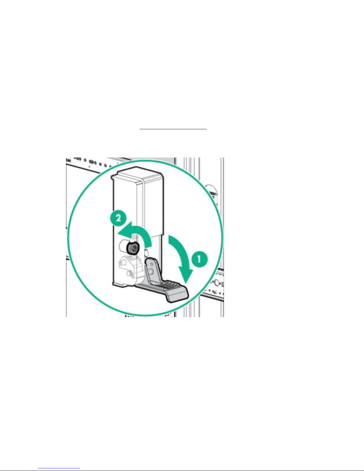
Procedure
1. Press the system locate UID button on the rear of the enclosure and locate the UID from the StoreVirtual
Management Console.
2. Press the system locate UID button the front of the enclosure, which turns on the system locate UID on the
rear of the enclosure.
All other LEDs mirror the state shown on the front of the enclosure.
Removing the UID health module
Procedure
1. Power off the enclosure.
2. Disconnect all cables from the enclosure, including the power cables.
3. Remove fan module 2. See Removing a fan module on page 62.
4. Loosen the rear CTO hold-down bracket.
5. Loosen the captive CTO screws (2) behind the latch (1) on the front left and right bezel ears of the
enclosure.
6. Slide the enclosure out of the rack and set it on a secure surface.
7. Pull the hood latch up and back (1 and 2), and lift the enclosure cover up and remove it (3).
Removing the UID health module 63
Page 64
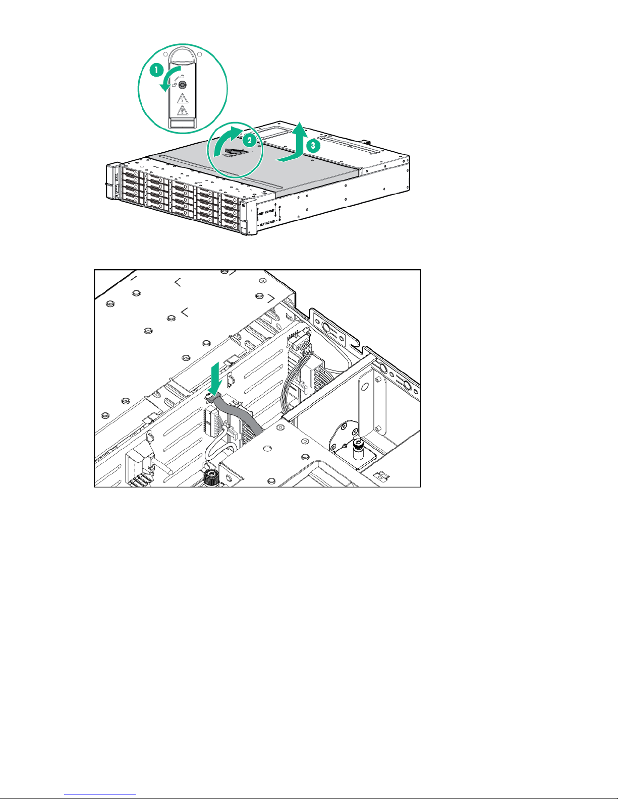
8. Disconnect the UID health module cable from the backplane.
9. Remove the UID health module retaining screw (1).
64 Removing and replacing hardware components
Page 65
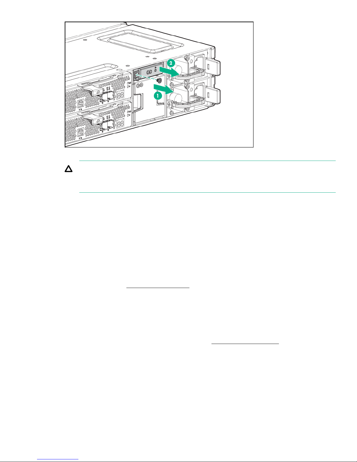
10. Slide the UID health module (2) out of the enclosure while guiding the cable through the enclosure.
CAUTION:
The UID cable is firmly adhered to the chassis. Care should be take to peel the UID cable carefully
off the enclosure chassis.
Installing the UID health module
Procedure
1. Install the replacement UID health module by sliding the cable through the slot in the enclosure.
2. Reconnect the UID health module cable to the backplane.
3. Adhere the UID health module to the chassis.
4. Fasten the UID health module using the retaining screw.
5. Install the enclosure cover and press the hood latch down to engage the latch.
6. Install the enclosure in the rack.
7. Tighten the front retaining screws.
8. Install fan module 2. See Installing a fan module on page 62.
9. Reconnect all cables to the enclosure, including the power cables.
Verifying UID health module operation
Procedure
1. When the enclosure has completed its power on sequence, check all enclosure status LEDs to ensure the
enclosure is operating properly. For more information, see Status LED descriptions on page 15.
Replacing the enclosure backplane
Before you begin
The procedure should be performed only if Hewlett Packard Enterprise Support has determined that the
enclosure backplane has failed and must be replaced.
Installing the UID health module 65
Page 66
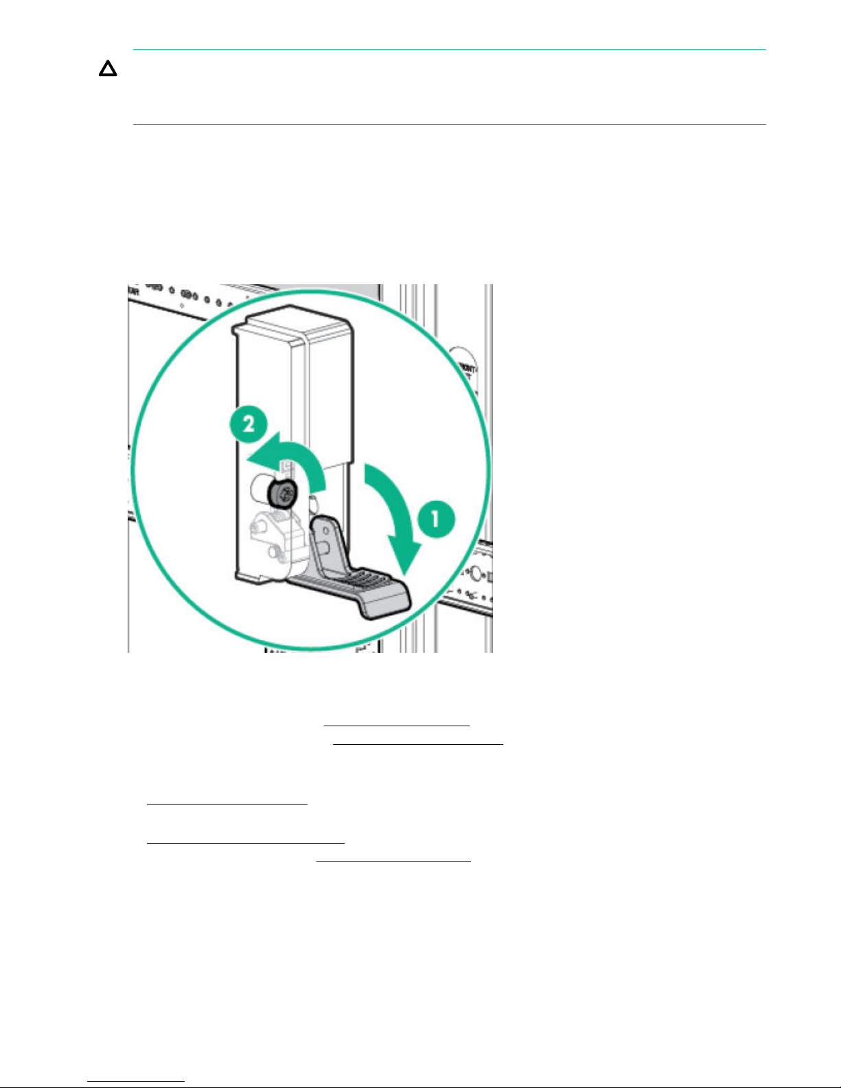
CAUTION:
This procedure requires removing the enclosure from the rack. Before removing the enclosure, ensure
that data on the system is backed up. Back up data if necessary.
Removing the enclosure backplane
Procedure
1. Disconnect all cables from the enclosure, including the power cables.
2. Loosen the rear CTO hold-down bracket.
3. Loosen the captive CTO screws (2) behind the latch (1) on the front left and right bezel ears of the
enclosure.
4. Slide the enclosure out of the rack and set it on a secure surface.
5. Label all the disk drives with the slot number before removing them to ensure they are reinstalled in the
proper enclosure bays.
6. Remove all the disk drives. See Removing a disk drive on page 52.
7. Remove the power supplies. See Removing a power supply on page 60.
8. Perform one of the following depending on which type of enclosure is involved.
a. If you are replacing the backplane in a drive enclosure, remove the I/O modules. See
Removing an I/O module on page 58.
b. If you are replacing the backplane in a array enclosure, remove the controller modules. See
Removing a controller module on page 56.
9. Remove the fan modules. See Removing a fan module on page 62.
10. Pull the hood latch up and back (1 and 2), and lift the enclosure cover up and remove it (3).
66 Removing the enclosure backplane
Page 67
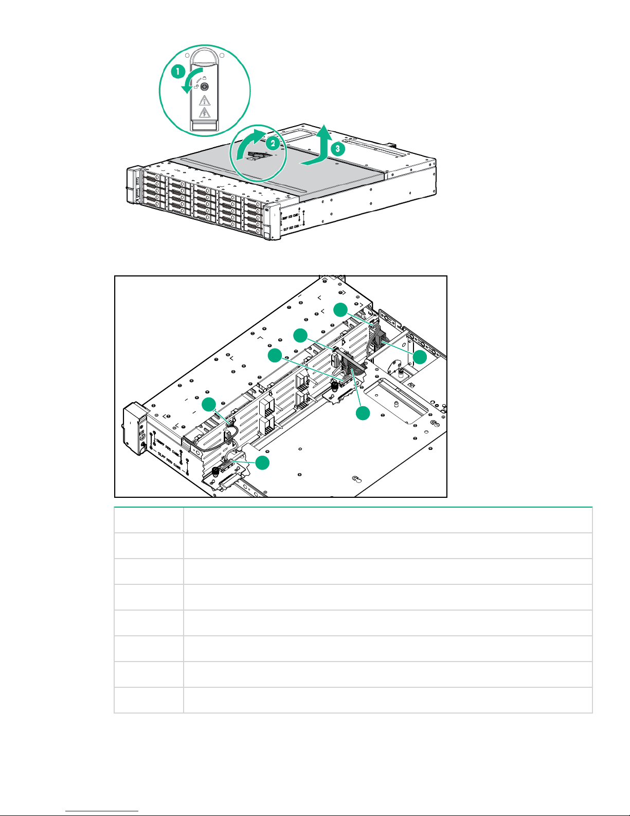
11. Disconnect the following cables from the backplane:
1
2
3
4
5
6
7
Number Cable
1 Front UID health module
2 Fan
3 Fan
4 Rear UID health module
5 Power distribution unit
6 Power supply
7 Power supply
12. Remove the eight drive cage retaining screws. There are four to each side.
Removing and replacing hardware components 67
Page 68
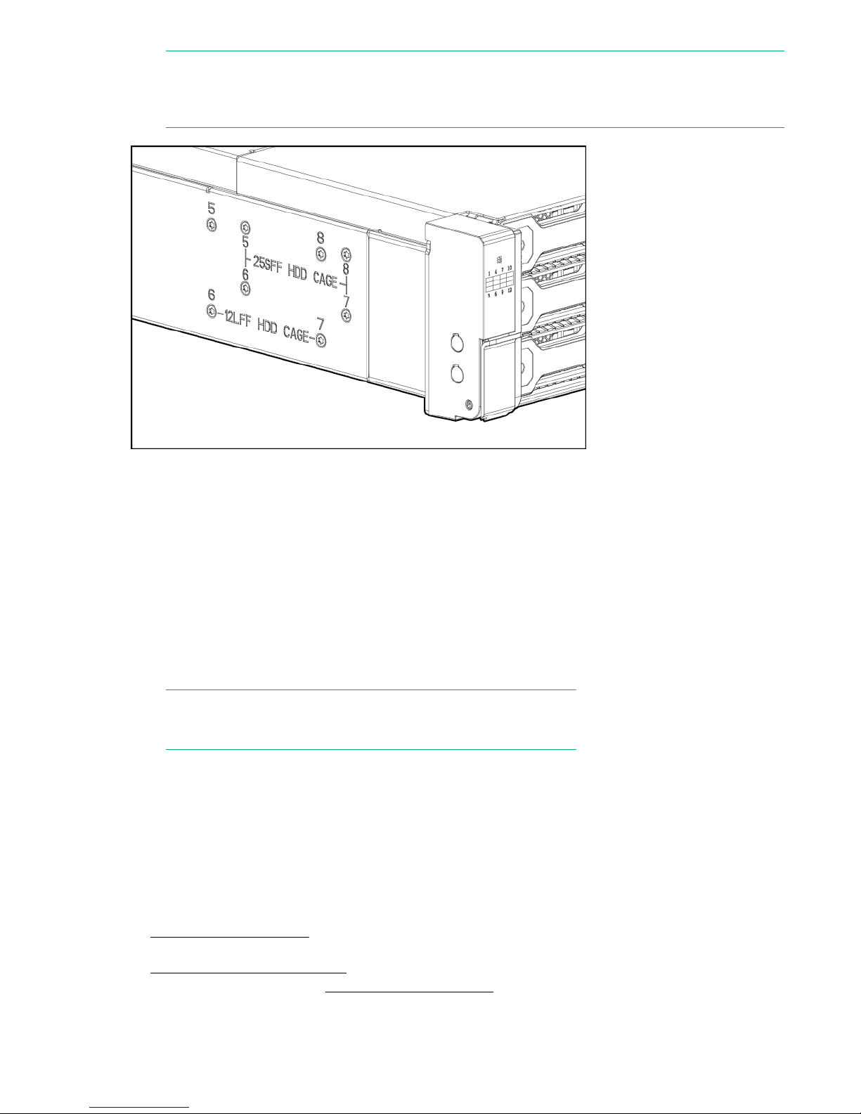
NOTE:
Depending on whether the drive cage is for LFF or SFF drives, the screws are in slightly different
locations.
13. Slide the drive cage toward the front of the enclosure and lift free of the enclosure.
14. Remove the two screws attaching the back plane to the drive cage.
15. Slide the backplane toward the top of the drive cage and lift the backplane off the drive cage.
Installing the enclosure backplane
Procedure
1. Place the replacement backplane on the drive cage and slide toward the bottom of the drive cage on to
the retaining hooks.
2. Install the two backplane screws.
3. Place the drive cage in the enclosure and slide it toward the back of the enclosure. Make sure that the
locating pins in the bottom of the enclosure are all correctly located in the drive cage.
NOTE:
Depending on the specific unit, there are six or eight locating pins.
4. Install the eight drive cage retaining screws.
5. Connect the two UID health module cables.
6. Connect the power cables.
7. Connect the fan cables.
8. Reconnect the power distribution unit.
9. Install the enclosure cover and press the hood latch down to engage the latch.
10. Slide the enclosure into the rack.
11. Perform one of the following depending on which type of enclosure is involved.
a. If you are replacing the backplane in a drive enclosure, install the top I/O modules only. See
Installing an I/O module on page 59.
b. If you are replacing the backplane in an array enclosure, install the top controller modules. See
Installing a controller module on page 57.
12. Install the power supplies. See Installing a power supply on page 61
68 Installing the enclosure backplane
Page 69
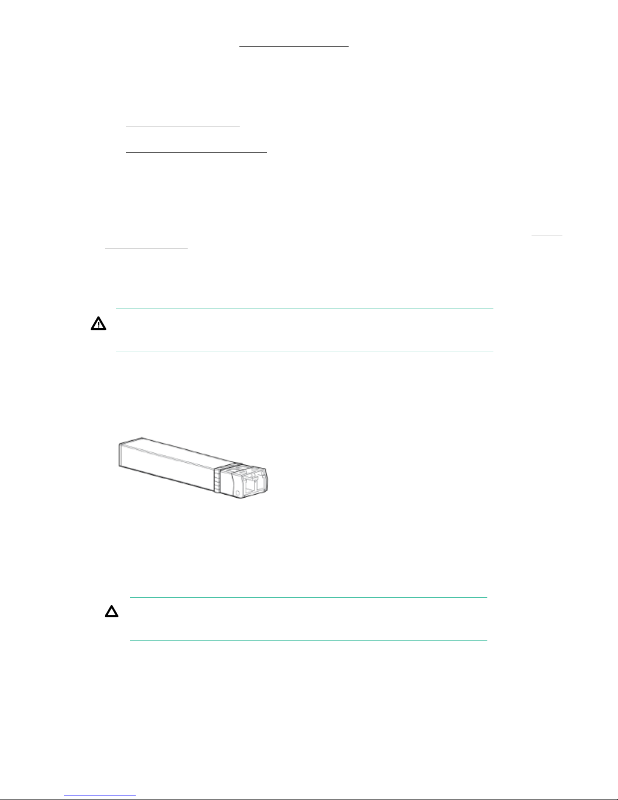
13. Install the fan modules. See Installing a fan module on page 62.
14. Install the disk drives in the same bays they were in the original enclosure. See Installing a disk drive.
15. Reconnect all cables to the enclosure, including the power cables.
16. When the enclosure has completed its power on sequence, perform one of the following depending on
which type of enclosure is involved.
a. If you are replacing the backplane in a drive enclosure, install the bottom I/O modules only. See
Installing an I/O module on page 59.
b. If you are replacing the backplane in an array enclosure, install the bottom controller modules. See
Installing a controller module on page 57 .
Verifying enclosure backplane operation
Procedure
1. When the second I/O module or controller module has completed its power on sequence, check all
enclosure status LEDs to ensure the enclosure is operating properly. For more information, see Status
LED descriptions on page 15.
Replacing a Fibre Channel SFP
The SFP is on the rear of the array enclosure and serves as the storage controller FC port.
WARNING:
When the system is on, do not stare at the fibers. Doing so could damage your eyes.
Removing a Fibre Channel SFP
Procedure
1. Disconnect the FC cable from the SFP.
2. Lift the retaining clip and carefully slide the SFP out of the enclosure.
Installing a Fibre Channel SFP
Procedure
1. Remove the replacement SFP module from its protective packaging.
CAUTION:
When handling the SFP, do not touch the gold contact leads to prevent damage.
2. Carefully slide the replacement SFP into the enclosure until fully seated.
3. Close the retaining clip to secure it in place.
4. Place the failed SFP into the packaging for return to Hewlett Packard Enterprise.
Verifying enclosure backplane operation 69
Page 70
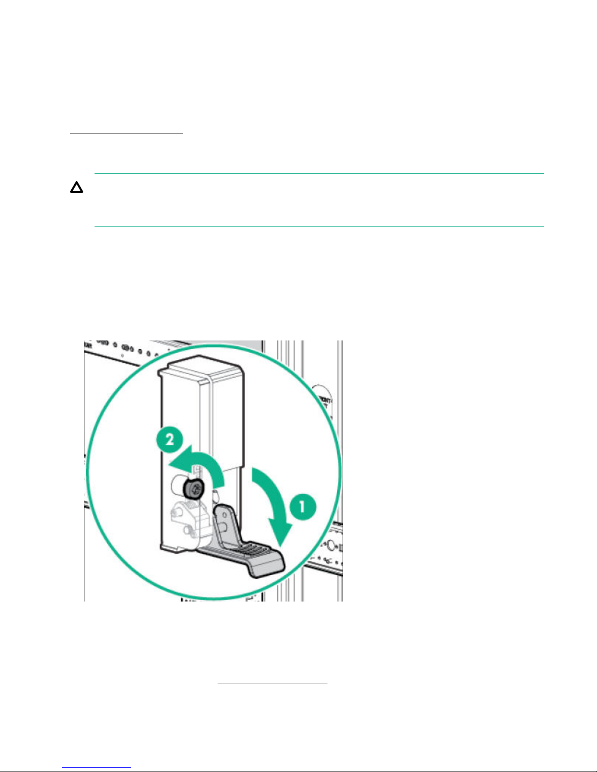
Verifying Fibre Channel SFP operation
Procedure
1. Reconnect the FC cable to the SFP and verify that the link status LED is solid green. For more information,
see "Related reference".
Related reference
Status LED descriptions on page 15
Removing and replacing the fan control card cable assembly
CAUTION:
This procedure requires removing the enclosure from the rack. Before removing the enclosure, ensure
that data on the system is backed up. Back up data if necessary.
Before removing the fan control card cable assembly
Procedure
1. Power off the array enclosure.
2. Disconnect all cables from the enclosure, including the power cables.
3. Loosen the captive CTO screws (2) behind the latch (1) on the front left and right bezel ears of the
enclosure.
4. Slide the enclosure out of the rack and set it on a secure surface.
5. Remove the rear CTO hold down bracket.
6. Remove the storage controller enclosure from the rack.
a. Back up all data before removing the enclosure from the rack.
b. Remove or unplug all cables.
7. Remove the fan modules. See Removing a fan module on page 62.
8. Pull the hood latch up and back (1 and 2), and lift the enclosure cover up and remove it (3).
70 Verifying Fibre Channel SFP operation
Page 71
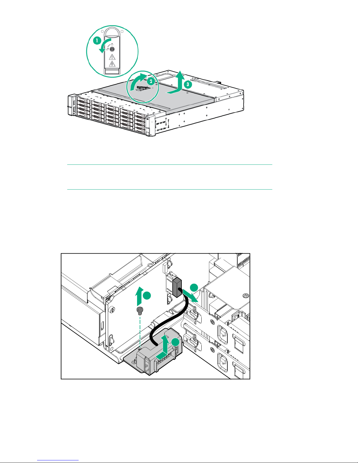
Removing the fan control card cable assembly
1
2
3
NOTE:
The fan control card cable assembly is between the backplane and fan module.
Procedure
1.
2. Remove fan control card cable from the backplane.
3. Remove the T-15 screw.
4. Slide the fan control card bracket sideways to free it from the retaining pins and lift it out.
5.
Remove the fan cable from the bracket.
6. Push the connector release in.
7. Slide the connector to keyed slots and push out.
Removing the fan control card cable assembly 71
Page 72
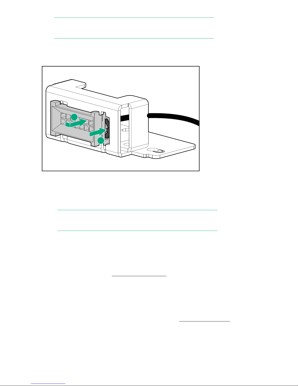
NOTE:
1
2
Slots are keyed and the fan cable assembly can only be installed one way.
8. Remove the fan cable.
1. Connector release 2. Keyed slots
Installing the fan control card assembly
Procedure
1. Slide the connector to keyed slots.
NOTE:
Slots are keyed and the fan cable assembly can only be installed one way.
2. Push the connector release in.
3. Add the fan cable to the bracket.
4. Insert the new fan control card and slide sideways to engage it with the retaining pins.
5. Reinstall the captive T-15 screw.
6. Attach the fan control card cable to the backplane.
7. Replace the enclosure cover and press the hood latch down to latch.
8. Replace the fan modules. See Replacing a fan module on page 61.
9. Replace the enclosure in the rack.
10. Install the captive CTO screws.
11. Tighten the front retaining screws.
12. Replace the I/O module cables.
13. Replace the power cables.
14. When the enclosure has completed its power on sequence, check all enclosure status LEDs to ensure
the enclosure is operating properly. For more information, see Common status LEDs on page 15.
72 Installing the fan control card assembly
Page 73
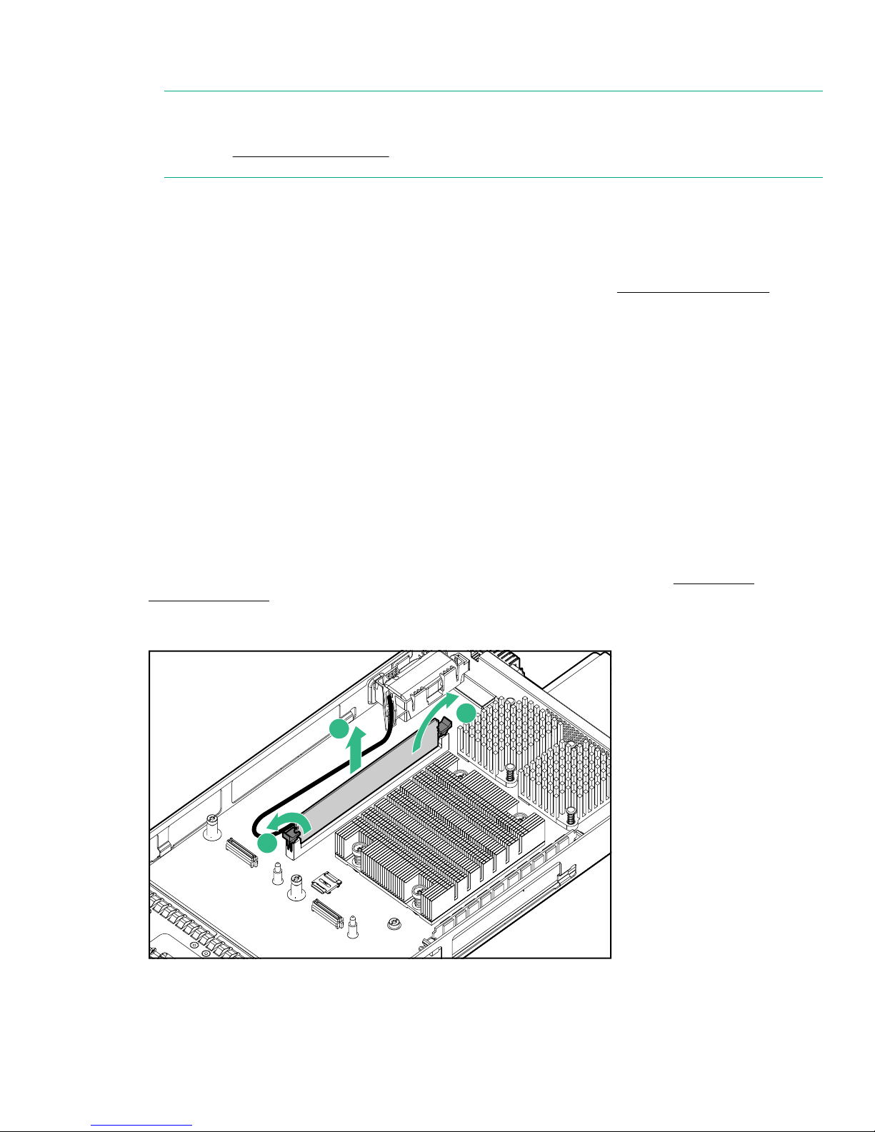
Removing and replacing Ethernet cables
1
1
2
NOTE:
If the cable is malfunctioning, check the LED displays on the I/O module or controller Data port back
panel. See Ethernet LED statuses on page 18 for LED status information.
Procedure
1. Confirm that you have the correct ports for the cables being replaced.
2. Disconnect the I/O/controller cables that you want to replace.
3. Replace the cables.
4. Confirm that the basic communication works using the LED statuses. See Ethernet LED statuses on
page 18 for LED status information.
Replacing the cache backup battery
Verifying cache backup battery failure
Procedure
1. The system monitors battery operation and logs any faults. Use the StoreVirtual Management Console to
view the battery status.
Removing the cache backup battery
Procedure
1. Remove the controller module from the array enclosure. For more information, see Removing a
controller module on page 56.
2. Remove the DIMM from the controller module by releasing the levers (1) and lifting the DIMM (2) out of the
socket.
3. Disconnect the battery cable from the DIMM.
Removing and replacing Ethernet cables 73
Page 74
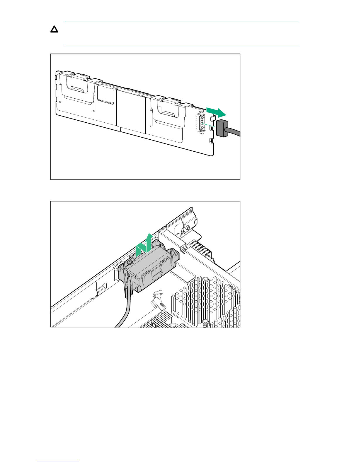
CAUTION:
Remove the battery cable gently. Do not allow the DIMM or battery to dangle by the cable.
4. Remove the battery from the controller module. Press the mounting tray tab on the side wall to release the
catch/lock.
5. Remove the battery from the mounting tray.
74 Removing and replacing hardware components
Page 75
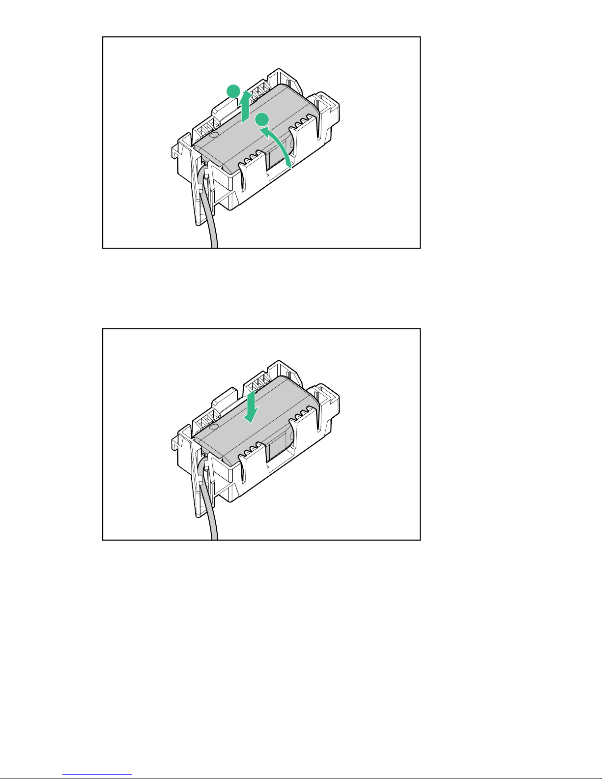
1
2
Installing the cache backup battery
Procedure
1. Install the replacement battery in the mounting tray.
2. Install the battery and mounting tray in the controller module. Ensure the tab snaps into place to secure the
mounting tray.
Installing the cache backup battery 75
Page 76
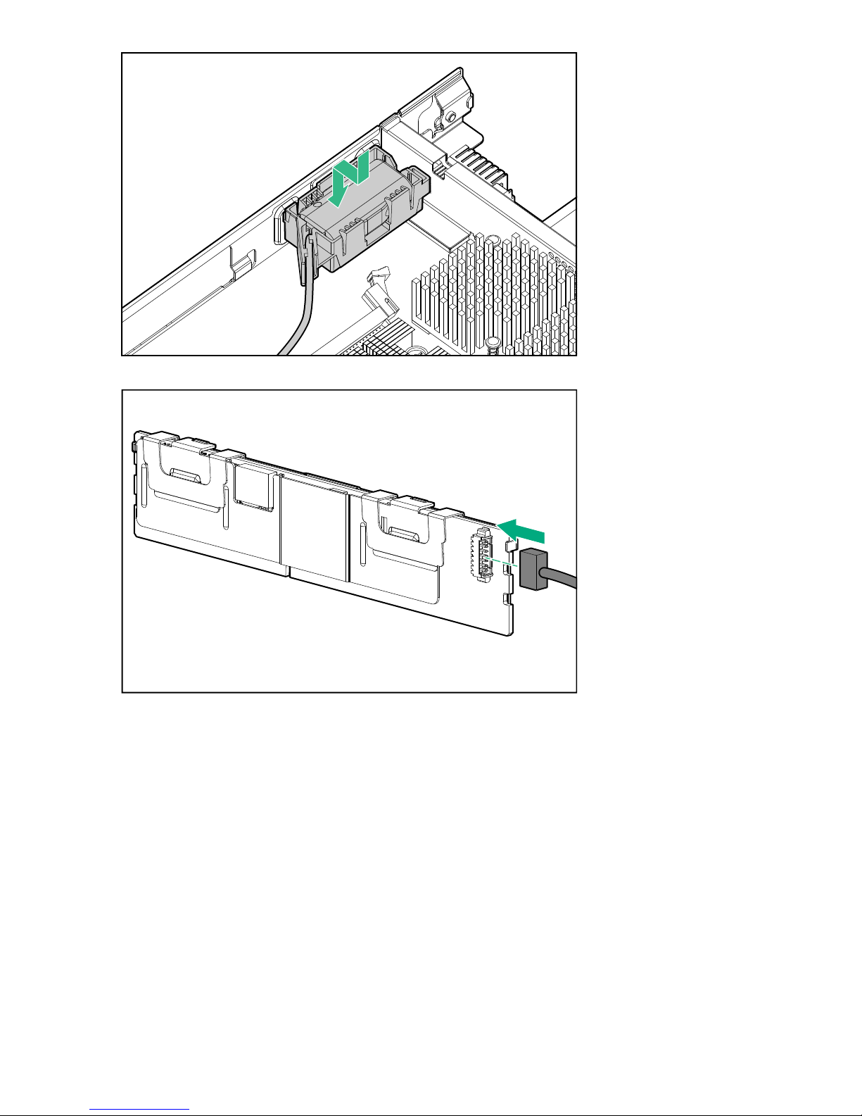
3. Connect the replacement battery cable to the DIMM.
4. Install the DIMM in the controller module by inserting the DIMM in the socket (1) and engaging the levers
(2).
76 Removing and replacing hardware components
Page 77
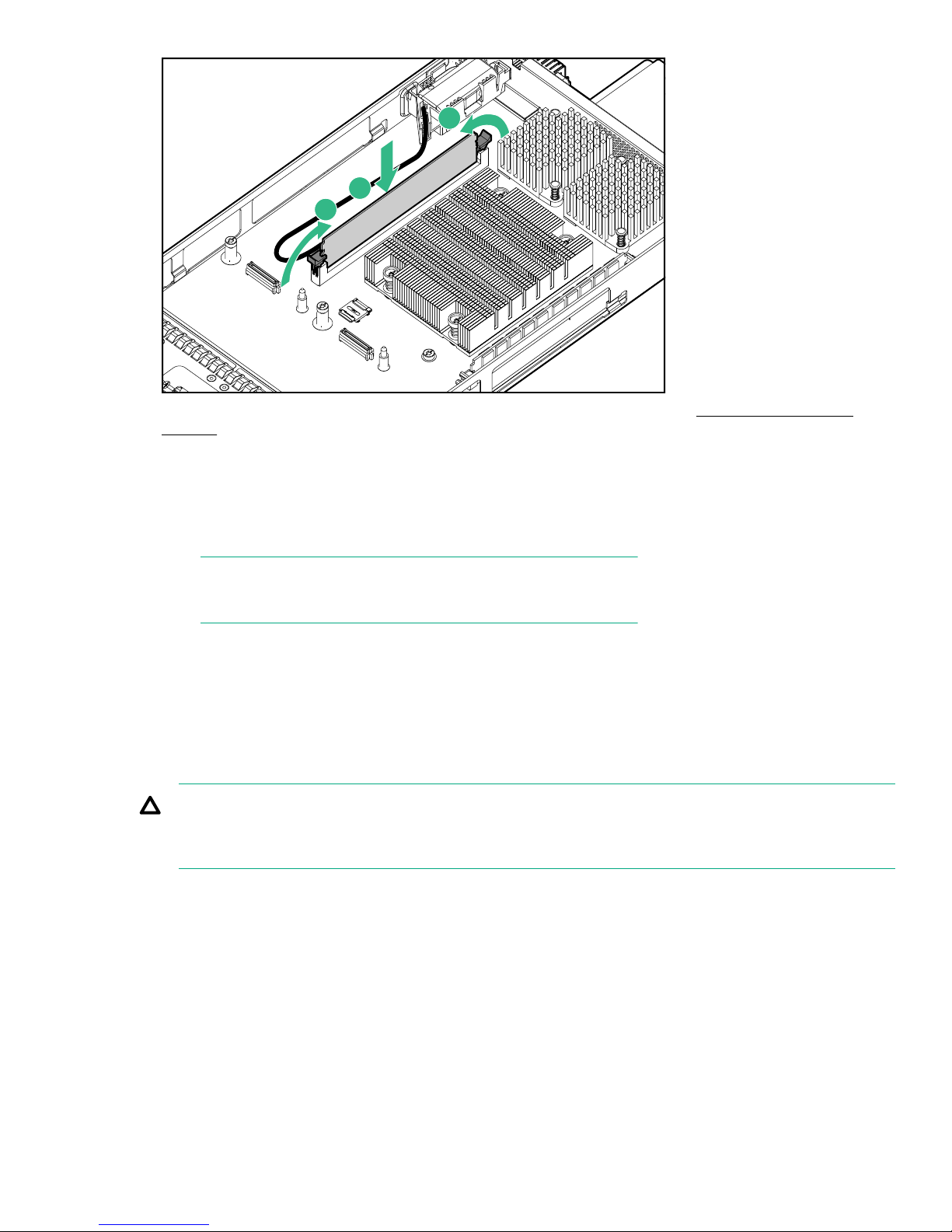
1
2
2
5. Install the controller module in the array enclosure. For more information, see Installing a controller
module on page 57.
Verifying cache backup battery operation
Procedure
1. View the StoreVirtual Management Console to ensure the cache mode is normal.
NOTE:
The battery may need time to charge before it is fully functional.
Replacing the intercontroller link (ICL)
Before you begin
The procedure should be performed only if Hewlett Packard Enterprise Support has determined that the ICL
has failed and must be replaced.
CAUTION:
This procedure requires removing the enclosure from the rack. Before removing the enclosure, ensure
that data on the system is backed up. Back up data if necessary.
Removing the ICL
Procedure
1. Power off the array enclosure.
2. Disconnect all cables from the enclosure, including the power cables.
3. Loosen the rear CTO hold-down bracket.
4. Loosen the captive CTO screws (2) behind the latch (1) on the front left and right bezel ears of the
enclosure.
Verifying cache backup battery operation 77
Page 78
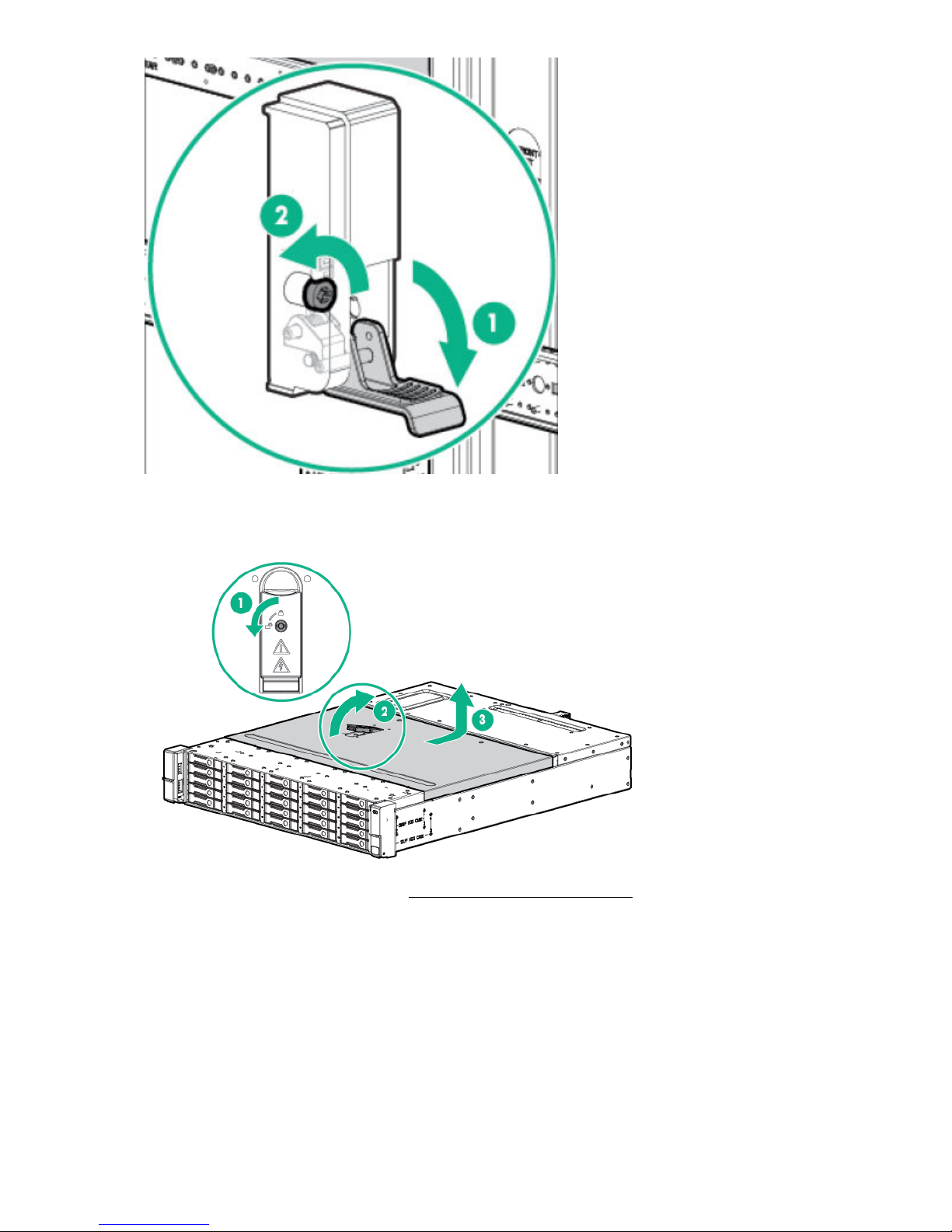
5. Slide the enclosure out of the rack and set it on a secure surface.
6. Remove the storage controller enclosure from the rack.
7. Pull the hood latch up and back (1 and 2), and lift the enclosure cover up and remove it (3).
8. Remove both controller modules. See Removing a controller module on page 56.
9. Remove the three ICL bracket mounting screws (1) and remove the bracket.
78 Removing and replacing hardware components
Page 79
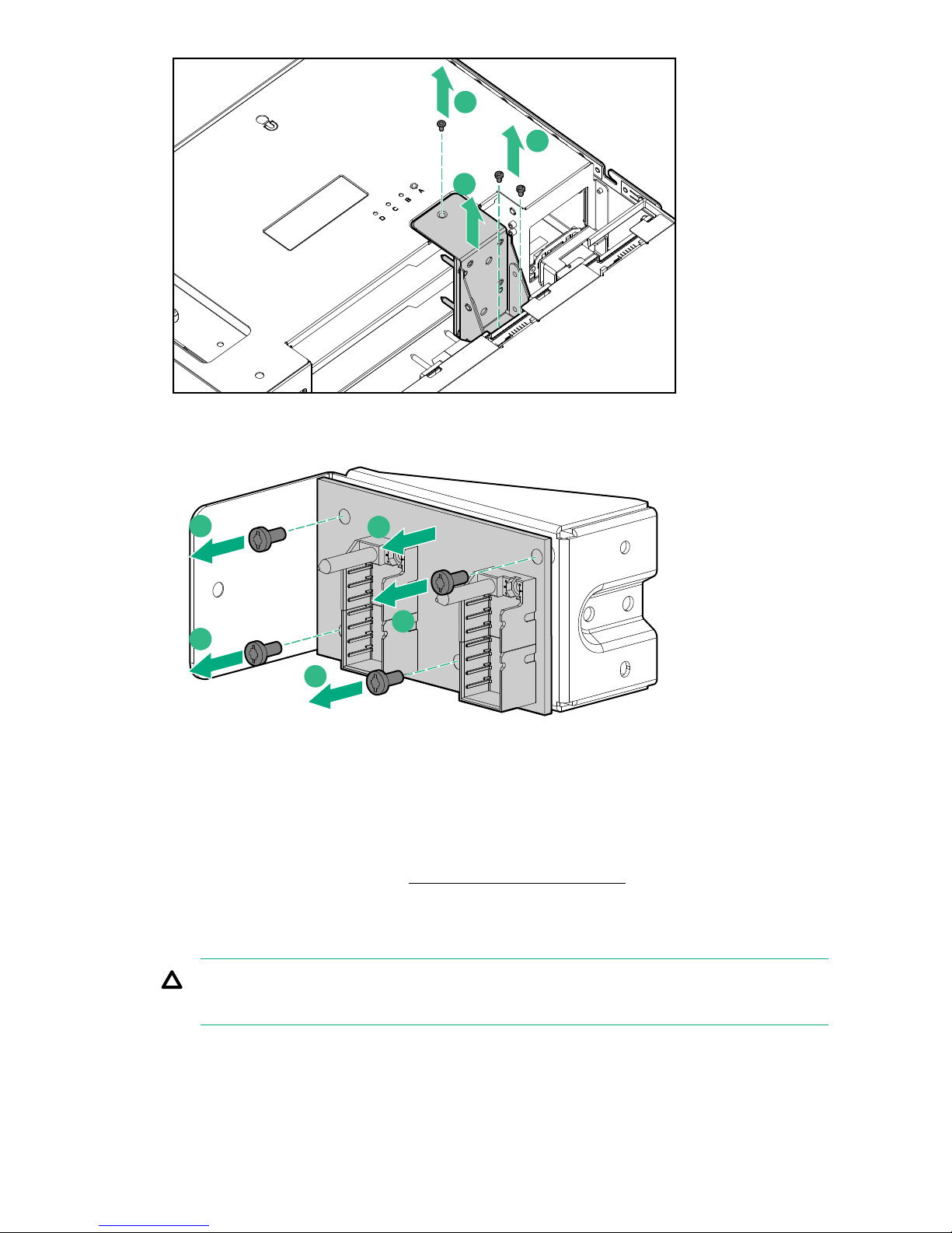
112
10. Remove the ICL board from the mounting bracket by removing the four mounting screws (1) as displayed
11112
in the following figure.
Installing the ICL
Procedure
1. Install the replacement ICL board on the mounting bracket using the four mounting screws.
2. Install the ICL bracket using the three bracket mounting screws.
3. Install both controller modules. See Installing a controller module on page 57.
4. Install the enclosure cover and press the hood latch down to engage the latch.
5. Install the enclosure in the rack.
6. Tighten the front retaining screws.
CAUTION:
The front CTO retaining screws must be attached at all times when the enclosure is racked.
7. Reconnect all cables to the enclosure, including the power cables.
Installing the ICL 79
Page 80

Verifying ICL operation
Procedure
1. When the enclosure has completed its power on sequence, inspect all enclosure status LEDs to ensure
that the enclosure is operating properly. For more information, see Status LED descriptions on page 15.
Migrating data from other StoreVirtual Storage systems
The StoreVirtual Migration Manager enables you to migrate data from a P4000 G2, StoreVirtual 4000, or
StoreVirtual VSA system to a StoreVirtual 3200 system. For more information, see the StoreVirtual Migration
Manager documentation (which includes a user guide and installation instructions) at http://www.hpe.com/
info/sv3200-docs.
80 Verifying ICL operation
Page 81

Remote support
Overview
Hewlett Packard Enterprise Remote Support with STaTS monitors your StoreVirtual 3200 storage system and
allows the storage system to proactively contact Hewlett Packard Enterprise if issues arise on the system. All
major (a warning in the event log) and minor (an alert in the event log) hardware events generate an alert that
is sent to the customer-specified user and to Hewlett Packard Enterprise Support. This alert automatically
opens a support case when action from Hewlett Packard Enterprise is required. Generally, these alerts
indicate that hardware should be replaced. Hewlett Packard Enterprise Support can then quickly ship
replacement parts to ensure optimal performance and availability. Remote Support submits data to Hewlett
Packard Enterprise Support using an HTTPS connection over the Internet. If needed, you can specify a web
proxy server to connect to the Internet. Alerts are transmitted over the firewall-friendly port 443.
NOTE:
Hewlett Packard Enterprise recommends entering the entitlement serial and product numbers even if
you do not intend to use Remote Support. The numbers are saved with the configuration and can be
restored when the configuration is restored.
Setting up customer information
Procedure
1. The Customer Information page displays the information of the person who should be contacted when
Remote Support indicates that a support case is needed.
Entering and modifying customer information
Procedure
1. From the StoreVirtual main menu, select Support.
2. Click Edit on the Customer Information page.
3. Enter or edit the contact information. The required fields are Email address or Phone number and
Country.
4. Click OK.
Remote support 81
Page 82
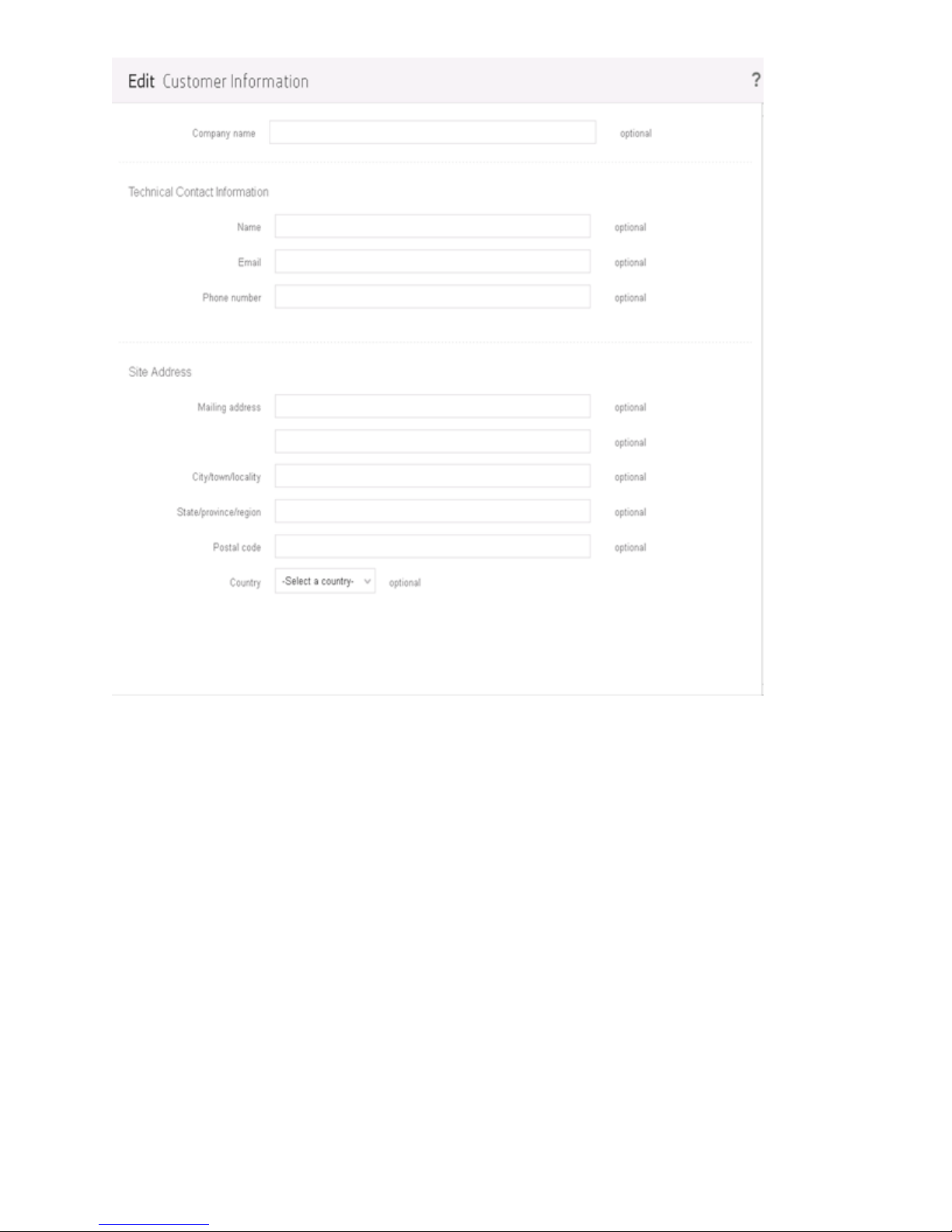
Figure 34: Edit customer information
Remote Support settings
Remote Support monitors your system and allows the system to proactively contact Hewlett Packard
Enterprise if issues arise.
Hewlett Packard Enterprise Remote Support page
The Remote Support page allows you to view the level of remote support.
82 Remote Support settings
Page 83
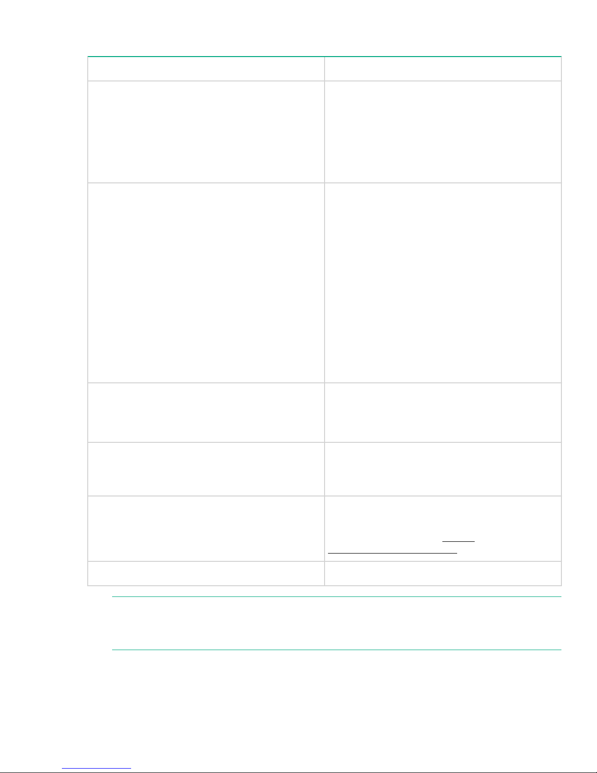
Table 15: Remote Support settings
Setting Description
Remote support level Describes the level of support configured on the
StoreVirtual appliance:
• Passive (default) – Allows events to be sent out
but does not permit inbound queries.
• No support – No events are sent out and does not
permit inbound queries (Remote Support is
disabled).
Allow contact from HPE and authorized
representatives.
Target HPE server The HPE server that receives the event messages.
Support from Select who will provide support: HPE Direct or HPE
If you select Yes, Hewlett Packard Enterprise and
partners may contact you to discuss optimization
options for your storage system. These options are
based on alerts and log file data that is sent with
Remote Support.
Additionally, Hewlett Packard Enterprise will continue
to contact you for support as needed, based on the
events sent with Remote Support.
If you select No, Hewlett Packard Enterprise and
partners will not contact you based on the data sent
back from Remote Support. If Remote Support is
disabled, then HPE support will not contact you
based on automated cases.
The server is automatically populated and must not
be changed unless you have a specific reason to do
so.
Partner. If you select HPE Partner, enter the Partner
ID in the appropriate field.
Support Identifier Enables viewing the storage device in the StoreFront
Custom delivery ID Customer-entered custom delivery ID
NOTE:
If you select Passive in the Remote support level field, you must complete the other fields. If you
select No Support, you do not have to complete any other fields.
Remote Manager
For more information, see https://
www.storefrontremote.com/.
Remote support 83
Page 84
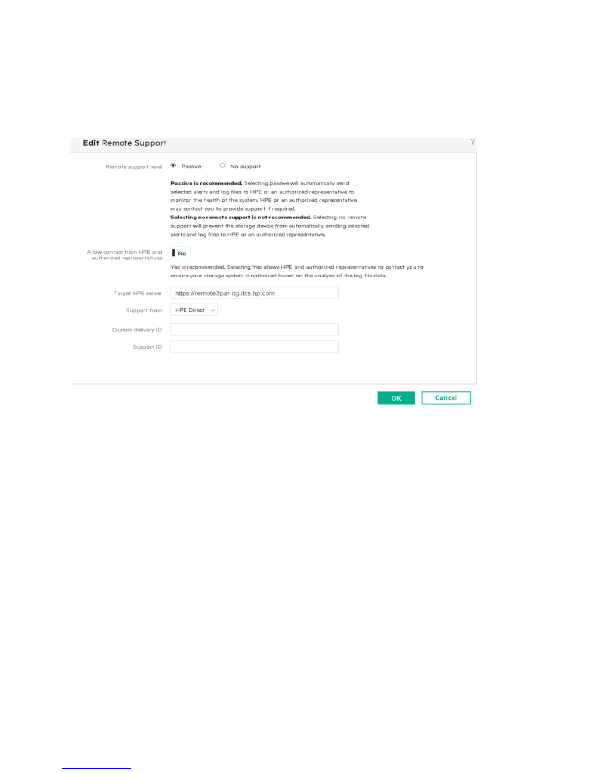
Configuring and modifying Remote Support
Procedure
1. From the StoreVirtual menu, select Support.
2. Click Edit on the Remote Support Settings page.
3. Enter or edit the appropriate information shown in Figure 35: Remote Support Settings page on page
84:
Figure 35: Remote Support Settings page
Proxy settings
The Proxy Settings page displays information about the proxy settings (if required) to connect to the target
HPE server.
Procedure
1. From the StoreVirtual main menu, select Settings.
2. Click Edit on the Proxy Settings page.
3. Enter or edit the appropriate information.
4. Click OK.
84 Configuring and modifying Remote Support
Page 85
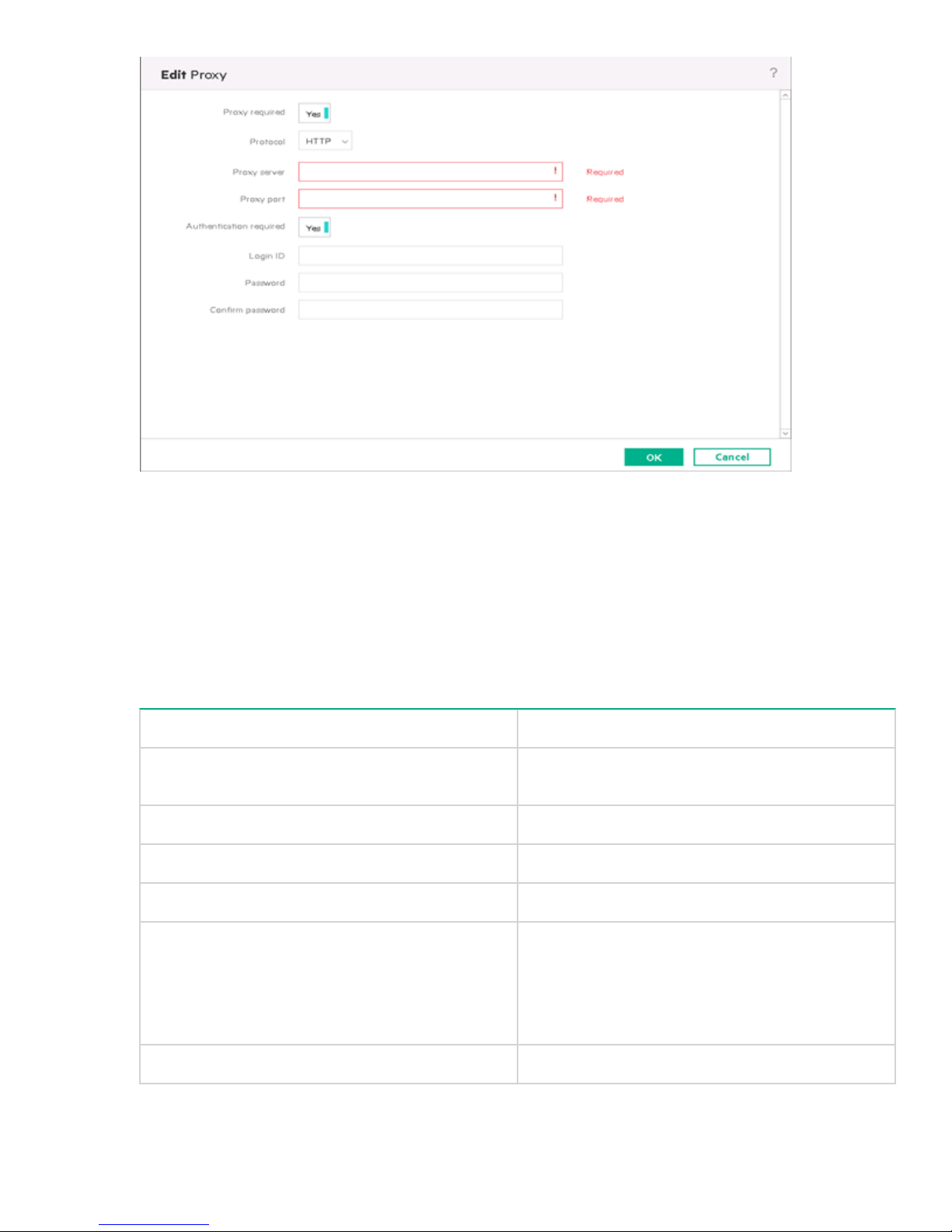
Figure 36: Proxy Settings page
The following table describes the proxy settings.
Table 16: Edit proxy settings.
Field Description
Proxy required If the proxy is required, this option allows the use of a
network proxy to access the Internet.
Protocol Protocol used by the proxy server.
Proxy server Proxy server IP address.
Port Port used by the proxy server.
Authentication required If authentication is required to access the proxy
server, the Login ID, Password, and Confirm
password fields are required. Clear this field if
authorization is not required to access the proxy.
, and
Login ID User name required to access the proxy server.
Table Continued
Remote support 85
Page 86

Field Description
Password Password required to access the proxy server.
Confirm password Re-enter the password for verification
RSvS alarms
Remote Support via STaTS (RSvS) alarms help to identify any Remote Support-specific issues.
Viewing RSvS alarms
To access RSvS alarms, select Active Alarms from the StoreVirtual main menu.
Table 17: RSvS alarm messages
Alarm message
1
EID_RSVS_SUMM_STATUS_NOT_ENABLED RSvS service not enabled.
EID_RSVS_CONFIG_MISSING This message appears for one of the following
EID_RSVS_CONN_STATUS_ERROR There are connectivity issues such as:
EID_RSVS_SUMM_STATUS_MAINTENANCE Device is under maintenance.
EID_RSVS_REG_STATUS_NOT_REGISTERED Device is not registered.
Description
reasons:
• Customer contact information is either not entered
or partially entered.
• A selection was not made indicating that HPE or
partners could contact you to suggest
optimizations.
• Entitlement information could not be acquired
from the system.
• Proxy server or Hewlett Packard Enterprise URL
is not reachable.
• DNS is not configured properly.
EID_RSVS_SUMM_STATUS_CORRUPT RSvS service is not started or the RSvS
EID_RSVS_SUMM_STATUS_ERROR • After the device is registered, the customer
1
All alarms displayed in this table have a "Warning" level alarm status.
86 RSvS alarms
configuration file is malformed.
contact information is either removed or partially
removed.
• Device is registered and there are connectivity
issues such as either the Proxy Server or the
Hewlett Packard Enterprise URL is not reachable.
Page 87
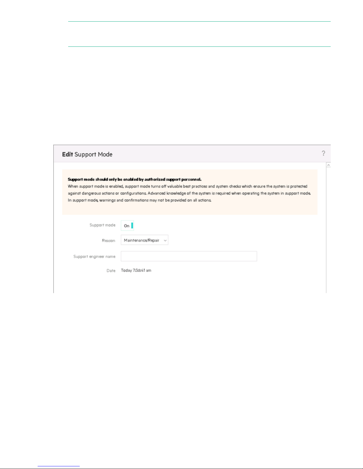
NOTE:
If you select No Support in the Remote support level field, no RSvS-specific alarms are displayed.
Support mode
The Target HPE server field on the Remote Support Settings page can only be changed when Support
mode is on.
To enable support mode:
Procedure
1. From the StoreVirtual main menu, select Support.
2. Click Edit on the Support Mode page.
3. Select Support mode and change the selection to On.
4. Click OK.
Figure 37: Support Mode page
Support mode 87
Page 88

Troubleshooting
Green activity LEDs do not work as expected during certain
activities
Symptom
The green activity LEDs on disk drives do not blink correctly during the following two activities:
• Initializing a new volume on a RAID array
• Rebuilding data on an activated hot spare disk drive
Cause
Due to a communication issue, the disk drive activity does not activate the green LEDs properly.
Action
Procedure
1. No action is required.
A disk enclosure from a 3PAR StoreServ installed into a
StoreVirtual 3200 Storage system results in the enclosure
status as unknown
Symptom
Installing a 3PAR StoreServ disk enclosure into a StoreVirtual 3200 Storage system results in the enclosure
status reporting unknown in the SVMC and via REST.
Cause
A 3PAR StoreServ enclosure is not compatible with the StoreVirtual array and should not be used.
Action
Procedure
1. Shut down the storage system and remove the 3PAR StoreServ disk enclosure.
An iSCSI volume that becomes unavailable for
approximately 60 seconds or less may cause data
unavailability
Symptom
If a Windows host that is configured with iSCSI on all available adapters experiences short multiple
disconnections on different adapters, it loses the paths to the disks. The lengths of these short disconnections
are less than one minute down and less than or equal to two minutes up.
88 Troubleshooting
Page 89

Cause
The Windows host does not recover from the disconnection in time and loses all paths to the volume. Extend
the time that the host continues to retry the connection by modifying the LinkDownTime registry key, so that
it has enough time to recover the paths. LinkDownTime determines how long requests will be held in the
device queue and retried if the connection to the target is lost. The default value is 15 seconds.
Action
Procedure
1. Change the Windows Registry setting for the default LinkDownTime to 120 seconds
1. Run regedit.exe.
2. Navigate to HKLM\SYSTEM\CurrentControlSet\Control\Class\{4D36E97B-E325-11CE-
3. Double-click LinkDownTime in the right-hand pane.
4. Enter a value of 120.
5. Click OK.
6. Save your changes and exit the Registry.
7. Reboot the system.
NOTE:
Back up your registry before changing it.
BFC1-08002BE10318}\<Instance Number>\Parameters.
The Edit DWord Value window opens.
RAID array remains degraded after hot spares rebuild
Symptom
After a disk drive fails and the disk drive designated as the hot spare is rebuilt, RAID remains in a degraded
state.
Cause
The RAID configuration remains degraded until the failed drives are replaced and the new drives rebuild.
Action
Procedure
1. Replace the failed drives. After the new drives rebuild, the degraded state clears.
Servicing controller incorrectly presented in the SVMC
Symptom
A RAID device is owned by only one controller in the storage system. This servicing controller may be
incorrectly presented in the SVMC.
Cause
The misreporting of the servicing controller can happen if all three following conditions are met:
• RAID has been configured
• A management group has not been created yet
• One of the storage controllers fails
RAID array remains degraded after hot spares rebuild 89
Page 90

Action
Procedure
1. You can ignore the information; the system will work as designed. The issue corrects itself once the failed
controller is replaced.
90 Troubleshooting
Page 91

Websites
General websites
Hewlett Packard Enterprise Information Library www.hpe.com/info/EIL
Single Point of Connectivity Knowledge (SPOCK) Storage
compatibility matrix
Storage white papers and analyst reports www.hpe.com/storage/whitepapers
For additional websites, see Support and other resources.
www.hpe.com/storage/spock
Websites 91
Page 92

Support and other resources
Accessing Hewlett Packard Enterprise Support
• For live assistance, go to the Contact Hewlett Packard Enterprise Worldwide website:
http://www.hpe.com/assistance
• To access documentation and support services, go to the Hewlett Packard Enterprise Support Center
website:
http://www.hpe.com/support/hpesc
Information to collect
• Technical support registration number (if applicable)
• Product name, model or version, and serial number
• Operating system name and version
• Firmware version
• Error messages
• Product-specific reports and logs
• Add-on products or components
• Third-party products or components
Accessing updates
• Some software products provide a mechanism for accessing software updates through the product
interface. Review your product documentation to identify the recommended software update method.
• To download product updates:
Hewlett Packard Enterprise Support Center www.hpe.com/support/hpesc
Hewlett Packard Enterprise Support Center: Software
downloads
Software Depot www.hpe.com/support/softwaredepot
• To subscribe to eNewsletters and alerts:
www.hpe.com/support/e-updates
• To view and update your entitlements, and to link your contracts and warranties with your profile, go to the
Hewlett Packard Enterprise Support Center More Information on Access to Support Materials page:
www.hpe.com/support/AccessToSupportMaterials
IMPORTANT:
Access to some updates might require product entitlement when accessed through the Hewlett Packard
Enterprise Support Center. You must have an HP Passport set up with relevant entitlements.
Customer self repair
www.hpe.com/support/downloads
Hewlett Packard Enterprise customer self repair (CSR) programs allow you to repair your product. If a CSR
part needs to be replaced, it will be shipped directly to you so that you can install it at your convenience.
Some parts do not qualify for CSR. Your Hewlett Packard Enterprise authorized service provider will
determine whether a repair can be accomplished by CSR.
92 Support and other resources
Page 93

For more information about CSR, contact your local service provider or go to the CSR website:
http://www.hpe.com/support/selfrepair
Remote support
Remote support is available with supported devices as part of your warranty or contractual support
agreement. It provides intelligent event diagnosis, and automatic, secure submission of hardware event
notifications to Hewlett Packard Enterprise, which will initiate a fast and accurate resolution based on your
product's service level. Hewlett Packard Enterprise strongly recommends that you register your device for
remote support.
If your product includes additional remote support details, use search to locate that information.
Remote support and Proactive Care information
HPE Get Connected www.hpe.com/services/getconnected
HPE Proactive Care services www.hpe.com/services/proactivecare
HPE Proactive Care service: Supported
products list
HPE Proactive Care advanced service:
Supported products list
Proactive Care customer information
Proactive Care central www.hpe.com/services/proactivecarecentral
Proactive Care service activation www.hpe.com/services/proactivecarecentralgetstarted
Warranty information
To view the warranty for your product, see the Safety and Compliance Information for Server, Storage, Power,
Networking, and Rack Products document, available at the Hewlett Packard Enterprise Support Center:
www.hpe.com/support/Safety-Compliance-EnterpriseProducts
Additional warranty information
HPE ProLiant and x86 Servers and Options www.hpe.com/support/ProLiantServers-Warranties
HPE Enterprise Servers www.hpe.com/support/EnterpriseServers-Warranties
HPE Storage Products www.hpe.com/support/Storage-Warranties
HPE Networking Products www.hpe.com/support/Networking-Warranties
www.hpe.com/services/proactivecaresupportedproducts
www.hpe.com/services/
proactivecareadvancedsupportedproducts
Regulatory information
To view the regulatory information for your product, view the Safety and Compliance Information for Server,
Storage, Power, Networking, and Rack Products, available at the Hewlett Packard Enterprise Support Center:
www.hpe.com/support/Safety-Compliance-EnterpriseProducts
Additional regulatory information
Hewlett Packard Enterprise is committed to providing our customers with information about the chemical
substances in our products as needed to comply with legal requirements such as REACH (Regulation EC No
1907/2006 of the European Parliament and the Council). A chemical information report for this product can be
found at:
Remote support 93
Page 94

www.hpe.com/info/reach
For Hewlett Packard Enterprise product environmental and safety information and compliance data, including
RoHS and REACH, see:
www.hpe.com/info/ecodata
For Hewlett Packard Enterprise environmental information, including company programs, product recycling,
and energy efficiency, see:
www.hpe.com/info/environment
Documentation feedback
Hewlett Packard Enterprise is committed to providing documentation that meets your needs. To help us
improve the documentation, send any errors, suggestions, or comments to Documentation Feedback
([email protected]). When submitting your feedback, include the document title, part number, edition,
and publication date located on the front cover of the document. For online help content, include the product
name, product version, help edition, and publication date located on the legal notices page.
94 Documentation feedback
Page 95
Warranty and regulatory information
For important safety, environmental, and regulatory information, see Safety and Compliance Information for
Server, Storage, Power, Networking, and Rack Products, available at
Compliance-EnterpriseProducts.
Warranty information
HPE ProLiant and x86 Servers and Options
www.hpe.com/support/ProLiantServers-Warranties
HPE Enterprise Servers
www.hpe.com/support/EnterpriseServers-Warranties
HPE Storage Products
www.hpe.com/support/Storage-Warranties
HPE Networking Products
www.hpe.com/support/Networking-Warranties
Regulatory information
www.hpe.com/support/Safety-
Belarus Kazakhstan Russia marking
Manufacturer and Local Representative Information
Manufacturer information:
• Hewlett Packard Enterprise Company, 3000 Hanover Street, Palo Alto, CA 94304 U.S.
Local representative information Russian:
• Russia:
• Belarus:
• Kazakhstan:
Local representative information Kazakh:
• Russia
Warranty and regulatory information 95
Page 96

:
• Belarus:
• Kazakhstan:
Manufacturing date:
The manufacturing date is defined by the serial number.
CCSYWWZZZZ (serial number format for this product)
Valid date formats include:
• YWW, where Y indicates the year counting from within each new decade, with 2000 as the starting point;
for example, 238: 2 for 2002 and 38 for the week of September 9. In addition, 2010 is indicated by 0, 2011
by 1, 2012 by 2, 2013 by 3, and so forth.
• YYWW, where YY indicates the year, using a base year of 2000; for example, 0238: 02 for 2002 and 38 for
the week of September 9.
Turkey RoHS material content declaration
Ukraine RoHS material content declaration
96 Turkey RoHS material content declaration
 Loading...