

Page 1

HP StorageWorks
Interface Manager and Command View for
Tape Libraries Software user guide
*12345-67890*
344841-010
Part number: 344841-010
Tenth edition: March 2006
Page 2

Legal and notice information
© Copyright 2003–2006 Hewlett-Packard Development Company, L.P.
Hewlett-Packard Company makes no warranty of any kind with regard to this material, including, but not limited to, the implied
warranties of merchantability and fitness for a particular purpose. Hewlett-Packard shall not be liable for errors contained herein or
for incidental or consequential damages in connection with the furnishing, performance, or use of this material.
This document contains proprietary information, which is protected by copyright. No part of this document may be photocopied,
reproduced, or translated into another language without the prior written consent of Hewlett-Packard. The information is provided
“as is” without warranty of any kind and is subject to change without notice. The only warranties for HP products and services are
set forth in the express warranty statements accompanying such products and services. Nothing herein should be construed as
constituting an additional warranty. HP shall not be liable for technical or editorial errors or omissions contained herein.
Microsoft, Windows, Windows NT, and Windows XP are U.S. registered trademarks of Microsoft Corporation.
Java™ is a US trademark of Sun Microsystems, Inc.
Interface Manager and Command View for Tape Libraries Software user guide
Page 3

Contents
About this guide . . . . . . . . . . . . . . . . . . . . . . . . . . . . . . . . . . . . . . . . . . . . . . . . . 9
Intended audience . . . . . . . . . . . . . . . . . . . . . . . . . . . . . . . . . . . . . . . . . . . . . . . . . . . . . . . . . 9
Related documentation . . . . . . . . . . . . . . . . . . . . . . . . . . . . . . . . . . . . . . . . . . . . . . . . . . . . . . 9
Document conventions and symbols . . . . . . . . . . . . . . . . . . . . . . . . . . . . . . . . . . . . . . . . . . . . 10
HP technical support . . . . . . . . . . . . . . . . . . . . . . . . . . . . . . . . . . . . . . . . . . . . . . . . . . . . . . . 11
Subscriber’s Choice alert notification registration. . . . . . . . . . . . . . . . . . . . . . . . . . . . . . . . . 11
HP-authorized reseller . . . . . . . . . . . . . . . . . . . . . . . . . . . . . . . . . . . . . . . . . . . . . . . . . . . 11
Helpful web sites . . . . . . . . . . . . . . . . . . . . . . . . . . . . . . . . . . . . . . . . . . . . . . . . . . . . . . . 11
Contents
1 Introduction . . . . . . . . . . . . . . . . . . . . . . . . . . . . . . . . . . . . . . . . . . . . . . . . . 13
SNIA compliance . . . . . . . . . . . . . . . . . . . . . . . . . . . . . . . . . . . . . . . . . . . . . . . . . . . . . . 13
User interfaces . . . . . . . . . . . . . . . . . . . . . . . . . . . . . . . . . . . . . . . . . . . . . . . . . . . . . . . . . . . 13
Order of precedence of user interfaces . . . . . . . . . . . . . . . . . . . . . . . . . . . . . . . . . . . . . . . . . . 14
Network configuration overview. . . . . . . . . . . . . . . . . . . . . . . . . . . . . . . . . . . . . . . . . . . . . . . 14
External features overview . . . . . . . . . . . . . . . . . . . . . . . . . . . . . . . . . . . . . . . . . . . . . . . . . . . 18
2 Command View for Tape Libraries Software . . . . . . . . . . . . . . . . . . . . . . . . . . . 19
Overview . . . . . . . . . . . . . . . . . . . . . . . . . . . . . . . . . . . . . . . . . . . . . . . . . . . . . . . . . . . . . . 19
Prerequisites . . . . . . . . . . . . . . . . . . . . . . . . . . . . . . . . . . . . . . . . . . . . . . . . . . . . . . . . . . . . 19
Installing Command View TL . . . . . . . . . . . . . . . . . . . . . . . . . . . . . . . . . . . . . . . . . . . . . . . . . 20
Starting Command View TL . . . . . . . . . . . . . . . . . . . . . . . . . . . . . . . . . . . . . . . . . . . . . . . . . . 20
Verifying connectivity with the Connectivity Check feature . . . . . . . . . . . . . . . . . . . . . . . . . . 21
Using the Launcher window . . . . . . . . . . . . . . . . . . . . . . . . . . . . . . . . . . . . . . . . . . . . . . . 22
Navigating Command View TL . . . . . . . . . . . . . . . . . . . . . . . . . . . . . . . . . . . . . . . . . . . . . 22
Device numbering conventions . . . . . . . . . . . . . . . . . . . . . . . . . . . . . . . . . . . . . . . . . . . . . 25
Initial configuration steps . . . . . . . . . . . . . . . . . . . . . . . . . . . . . . . . . . . . . . . . . . . . . . . . . . . . 26
Other common Command View TL functions . . . . . . . . . . . . . . . . . . . . . . . . . . . . . . . . . . . . . . 26
Adding or removing a library . . . . . . . . . . . . . . . . . . . . . . . . . . . . . . . . . . . . . . . . . . . . . . 27
Using the Library Discovery wizard . . . . . . . . . . . . . . . . . . . . . . . . . . . . . . . . . . . . . . . . 27
Manually adding or removing a library . . . . . . . . . . . . . . . . . . . . . . . . . . . . . . . . . . . . . 28
Configuring a library . . . . . . . . . . . . . . . . . . . . . . . . . . . . . . . . . . . . . . . . . . . . . . . . . . . . 29
Configuring the Fibre Channel interface controllers . . . . . . . . . . . . . . . . . . . . . . . . . . . . . . . 30
Monitoring device status. . . . . . . . . . . . . . . . . . . . . . . . . . . . . . . . . . . . . . . . . . . . . . . . . . 30
Viewing the event log. . . . . . . . . . . . . . . . . . . . . . . . . . . . . . . . . . . . . . . . . . . . . . . . . . . . 31
Viewing inventory of the library. . . . . . . . . . . . . . . . . . . . . . . . . . . . . . . . . . . . . . . . . . . . . 32
Updating firmware. . . . . . . . . . . . . . . . . . . . . . . . . . . . . . . . . . . . . . . . . . . . . . . . . . . . . . 32
Using the License Manager . . . . . . . . . . . . . . . . . . . . . . . . . . . . . . . . . . . . . . . . . . . . . . . . 35
Library Selection tab . . . . . . . . . . . . . . . . . . . . . . . . . . . . . . . . . . . . . . . . . . . . . . . . . . . . . . . 36
Adding and removing libraries . . . . . . . . . . . . . . . . . . . . . . . . . . . . . . . . . . . . . . . . . . . . . 36
Interface Manager and Command View for Tape Libraries Software user guide 3
Page 4

Managing libraries . . . . . . . . . . . . . . . . . . . . . . . . . . . . . . . . . . . . . . . . . . . . . . . . . . . . . 36
Identity tab. . . . . . . . . . . . . . . . . . . . . . . . . . . . . . . . . . . . . . . . . . . . . . . . . . . . . . . . . 37
Status tab . . . . . . . . . . . . . . . . . . . . . . . . . . . . . . . . . . . . . . . . . . . . . . . . . . . . . . . . . 37
Health summary. . . . . . . . . . . . . . . . . . . . . . . . . . . . . . . . . . . . . . . . . . . . . . . . . . . 38
Cabling view. . . . . . . . . . . . . . . . . . . . . . . . . . . . . . . . . . . . . . . . . . . . . . . . . . . . . 39
Component Status . . . . . . . . . . . . . . . . . . . . . . . . . . . . . . . . . . . . . . . . . . . . . . . . . 39
Event log . . . . . . . . . . . . . . . . . . . . . . . . . . . . . . . . . . . . . . . . . . . . . . . . . . . . . . . 40
Inventory. . . . . . . . . . . . . . . . . . . . . . . . . . . . . . . . . . . . . . . . . . . . . . . . . . . . . . . . 40
Configuration tab . . . . . . . . . . . . . . . . . . . . . . . . . . . . . . . . . . . . . . . . . . . . . . . . . . . . 41
Library properties. . . . . . . . . . . . . . . . . . . . . . . . . . . . . . . . . . . . . . . . . . . . . . . . . . 42
Interface settings . . . . . . . . . . . . . . . . . . . . . . . . . . . . . . . . . . . . . . . . . . . . . . . . . . 42
Interface Manager mode . . . . . . . . . . . . . . . . . . . . . . . . . . . . . . . . . . . . . . . . . . 42
Connection properties . . . . . . . . . . . . . . . . . . . . . . . . . . . . . . . . . . . . . . . . . . . . 43
WWN retention . . . . . . . . . . . . . . . . . . . . . . . . . . . . . . . . . . . . . . . . . . . . . . . . . . 44
Clearing a WWN mismatch. . . . . . . . . . . . . . . . . . . . . . . . . . . . . . . . . . . . . . . . 44
Replacing an interface controller with WWN retention enabled . . . . . . . . . . . . . . . 45
Host access (Secure Manager) . . . . . . . . . . . . . . . . . . . . . . . . . . . . . . . . . . . . . . . . 46
Partitioning . . . . . . . . . . . . . . . . . . . . . . . . . . . . . . . . . . . . . . . . . . . . . . . . . . . . . . 46
Direct backup . . . . . . . . . . . . . . . . . . . . . . . . . . . . . . . . . . . . . . . . . . . . . . . . . . . . 46
Network settings . . . . . . . . . . . . . . . . . . . . . . . . . . . . . . . . . . . . . . . . . . . . . . . . . . 46
TCP/IP. . . . . . . . . . . . . . . . . . . . . . . . . . . . . . . . . . . . . . . . . . . . . . . . . . . . . . . 47
SNMP alerts. . . . . . . . . . . . . . . . . . . . . . . . . . . . . . . . . . . . . . . . . . . . . . . . . . . 47
Licensed Capacity Panel Upgrade for ESL E-Series feature. . . . . . . . . . . . . . . . . . . . . . 48
Save/Restore feature . . . . . . . . . . . . . . . . . . . . . . . . . . . . . . . . . . . . . . . . . . . . . . . 49
Operations tab. . . . . . . . . . . . . . . . . . . . . . . . . . . . . . . . . . . . . . . . . . . . . . . . . . . . . . 49
Reboot . . . . . . . . . . . . . . . . . . . . . . . . . . . . . . . . . . . . . . . . . . . . . . . . . . . . . . . . . 50
Media management . . . . . . . . . . . . . . . . . . . . . . . . . . . . . . . . . . . . . . . . . . . . . . . . 51
Support tab . . . . . . . . . . . . . . . . . . . . . . . . . . . . . . . . . . . . . . . . . . . . . . . . . . . . . . . . 52
HP on the Web . . . . . . . . . . . . . . . . . . . . . . . . . . . . . . . . . . . . . . . . . . . . . . . . . . . 52
Support ticket . . . . . . . . . . . . . . . . . . . . . . . . . . . . . . . . . . . . . . . . . . . . . . . . . . . . 52
Firmware update . . . . . . . . . . . . . . . . . . . . . . . . . . . . . . . . . . . . . . . . . . . . . . . . . . 53
Restore factory defaults. . . . . . . . . . . . . . . . . . . . . . . . . . . . . . . . . . . . . . . . . . . . . . 55
Management Station tab . . . . . . . . . . . . . . . . . . . . . . . . . . . . . . . . . . . . . . . . . . . . . . . . . . . . 56
Network settings . . . . . . . . . . . . . . . . . . . . . . . . . . . . . . . . . . . . . . . . . . . . . . . . . . . . . . . 56
E-mail settings . . . . . . . . . . . . . . . . . . . . . . . . . . . . . . . . . . . . . . . . . . . . . . . . . . . . . . . . . 57
Administrative password. . . . . . . . . . . . . . . . . . . . . . . . . . . . . . . . . . . . . . . . . . . . . . . . . . 57
License Key Summary tab . . . . . . . . . . . . . . . . . . . . . . . . . . . . . . . . . . . . . . . . . . . . . . . . . . . 57
Adding or removing a license key . . . . . . . . . . . . . . . . . . . . . . . . . . . . . . . . . . . . . . . . . . . 59
Support Tickets tab . . . . . . . . . . . . . . . . . . . . . . . . . . . . . . . . . . . . . . . . . . . . . . . . . . . . . . . . 59
3 Command line interface . . . . . . . . . . . . . . . . . . . . . . . . . . . . . . . . . . . . . . . . . 61
Accessing the CLI . . . . . . . . . . . . . . . . . . . . . . . . . . . . . . . . . . . . . . . . . . . . . . . . . . . . . . . . . 61
Starting a serial session . . . . . . . . . . . . . . . . . . . . . . . . . . . . . . . . . . . . . . . . . . . . . . . . . . 61
Starting a Telnet session . . . . . . . . . . . . . . . . . . . . . . . . . . . . . . . . . . . . . . . . . . . . . . . . . . 62
Telnetting through the LAN. . . . . . . . . . . . . . . . . . . . . . . . . . . . . . . . . . . . . . . . . . . . . . 62
Telnetting through the cascade port. . . . . . . . . . . . . . . . . . . . . . . . . . . . . . . . . . . . . . . . 63
4
Page 5

Command syntax structure. . . . . . . . . . . . . . . . . . . . . . . . . . . . . . . . . . . . . . . . . . . . . . . . . . . 64
Using command sequences. . . . . . . . . . . . . . . . . . . . . . . . . . . . . . . . . . . . . . . . . . . . . . . . 64
Abbreviating commands. . . . . . . . . . . . . . . . . . . . . . . . . . . . . . . . . . . . . . . . . . . . . . . . . . 65
Device numbering conventions . . . . . . . . . . . . . . . . . . . . . . . . . . . . . . . . . . . . . . . . . . . . . 65
Navigating the CLI. . . . . . . . . . . . . . . . . . . . . . . . . . . . . . . . . . . . . . . . . . . . . . . . . . . . . . 66
Interface Manager mode . . . . . . . . . . . . . . . . . . . . . . . . . . . . . . . . . . . . . . . . . . . . . . . . . . . . 67
Common CLI functions. . . . . . . . . . . . . . . . . . . . . . . . . . . . . . . . . . . . . . . . . . . . . . . . . . . . . . 67
Using the Setup Wizard . . . . . . . . . . . . . . . . . . . . . . . . . . . . . . . . . . . . . . . . . . . . . . . . . . 68
Configuring a library . . . . . . . . . . . . . . . . . . . . . . . . . . . . . . . . . . . . . . . . . . . . . . . . . . . . 68
Configuring the FC interface controllers . . . . . . . . . . . . . . . . . . . . . . . . . . . . . . . . . . . . . . . 68
Monitoring device status. . . . . . . . . . . . . . . . . . . . . . . . . . . . . . . . . . . . . . . . . . . . . . . . . . 68
Generating Interface Manager and FC interface controller logs . . . . . . . . . . . . . . . . . . . . . . . 69
Updating firmware. . . . . . . . . . . . . . . . . . . . . . . . . . . . . . . . . . . . . . . . . . . . . . . . . . . . . . 70
Generating support tickets from the CLI . . . . . . . . . . . . . . . . . . . . . . . . . . . . . . . . . . . . . . . 71
Using Secure Manager functions . . . . . . . . . . . . . . . . . . . . . . . . . . . . . . . . . . . . . . . . . . . . 72
Accessing basic Secure Manager through the CLI . . . . . . . . . . . . . . . . . . . . . . . . . . . . . . 73
4 Advanced features . . . . . . . . . . . . . . . . . . . . . . . . . . . . . . . . . . . . . . . . . . . . 75
Direct Backup Engine . . . . . . . . . . . . . . . . . . . . . . . . . . . . . . . . . . . . . . . . . . . . . . . . . . . . . . 75
Requirements . . . . . . . . . . . . . . . . . . . . . . . . . . . . . . . . . . . . . . . . . . . . . . . . . . . . . . . . . 76
Using Direct Backup. . . . . . . . . . . . . . . . . . . . . . . . . . . . . . . . . . . . . . . . . . . . . . . . . . . . . 76
Enabling Direct Backup on tape drives . . . . . . . . . . . . . . . . . . . . . . . . . . . . . . . . . . . . . . . . 76
Secure Manager . . . . . . . . . . . . . . . . . . . . . . . . . . . . . . . . . . . . . . . . . . . . . . . . . . . . . . . . . 78
Requirements . . . . . . . . . . . . . . . . . . . . . . . . . . . . . . . . . . . . . . . . . . . . . . . . . . . . . . . . . 78
Configuring host access . . . . . . . . . . . . . . . . . . . . . . . . . . . . . . . . . . . . . . . . . . . . . . . . . . 78
Adding or removing a host HBA from the list . . . . . . . . . . . . . . . . . . . . . . . . . . . . . . . . . 79
Editing the host HBA alias . . . . . . . . . . . . . . . . . . . . . . . . . . . . . . . . . . . . . . . . . . . . . . 80
Viewing host HBA properties . . . . . . . . . . . . . . . . . . . . . . . . . . . . . . . . . . . . . . . . . . . . 80
Configuring access for a host HBA . . . . . . . . . . . . . . . . . . . . . . . . . . . . . . . . . . . . . . . . 80
Viewing the device map . . . . . . . . . . . . . . . . . . . . . . . . . . . . . . . . . . . . . . . . . . . . . . . 81
Partitioning a library . . . . . . . . . . . . . . . . . . . . . . . . . . . . . . . . . . . . . . . . . . . . . . . . . . . . 81
Adding a partition . . . . . . . . . . . . . . . . . . . . . . . . . . . . . . . . . . . . . . . . . . . . . . . . . . . 81
Removing a partition . . . . . . . . . . . . . . . . . . . . . . . . . . . . . . . . . . . . . . . . . . . . . . . . . . 82
Viewing partition properties . . . . . . . . . . . . . . . . . . . . . . . . . . . . . . . . . . . . . . . . . . . . . 83
Using the Licensed Capacity Panel Upgrade for ESL E-Series feature . . . . . . . . . . . . . . . . . . . . . . 83
Obtaining and installing license keys . . . . . . . . . . . . . . . . . . . . . . . . . . . . . . . . . . . . . . . . . . . 84
Installing the license keys . . . . . . . . . . . . . . . . . . . . . . . . . . . . . . . . . . . . . . . . . . . . . . . . . 84
Considerations . . . . . . . . . . . . . . . . . . . . . . . . . . . . . . . . . . . . . . . . . . . . . . . . . . . . . . 84
Installing . . . . . . . . . . . . . . . . . . . . . . . . . . . . . . . . . . . . . . . . . . . . . . . . . . . . . . . . . . 84
Using support tickets . . . . . . . . . . . . . . . . . . . . . . . . . . . . . . . . . . . . . . . . . . . . . . . . . . . . . . . 85
Generating a support ticket. . . . . . . . . . . . . . . . . . . . . . . . . . . . . . . . . . . . . . . . . . . . . . . . 85
Viewing a support ticket . . . . . . . . . . . . . . . . . . . . . . . . . . . . . . . . . . . . . . . . . . . . . . . . . . 85
Sending a support ticket by e-mail . . . . . . . . . . . . . . . . . . . . . . . . . . . . . . . . . . . . . . . . . . . 87
Other support ticket functionality . . . . . . . . . . . . . . . . . . . . . . . . . . . . . . . . . . . . . . . . . . . . 87
Interface Manager and Command View for Tape Libraries Software user guide 5
Page 6

5 Troubleshooting . . . . . . . . . . . . . . . . . . . . . . . . . . . . . . . . . . . . . . . . . . . . . . 89
LED diagnostic codes . . . . . . . . . . . . . . . . . . . . . . . . . . . . . . . . . . . . . . . . . . . . . . . . . . . . . . 89
Common issues . . . . . . . . . . . . . . . . . . . . . . . . . . . . . . . . . . . . . . . . . . . . . . . . . . . . . . . . . . 91
A CLI Command Reference . . . . . . . . . . . . . . . . . . . . . . . . . . . . . . . . . . . . . . . . 99
User commands . . . . . . . . . . . . . . . . . . . . . . . . . . . . . . . . . . . . . . . . . . . . . . . . . . . . . . . . . . 99
add directbackup . . . . . . . . . . . . . . . . . . . . . . . . . . . . . . . . . . . . . . . . . . . . . . . . . . . . . 100
create host . . . . . . . . . . . . . . . . . . . . . . . . . . . . . . . . . . . . . . . . . . . . . . . . . . . . . . . . . . 101
delete directbackup . . . . . . . . . . . . . . . . . . . . . . . . . . . . . . . . . . . . . . . . . . . . . . . . . . . . 102
download interface . . . . . . . . . . . . . . . . . . . . . . . . . . . . . . . . . . . . . . . . . . . . . . . . . . . . 103
download drive. . . . . . . . . . . . . . . . . . . . . . . . . . . . . . . . . . . . . . . . . . . . . . . . . . . . . . . 105
download mgmt . . . . . . . . . . . . . . . . . . . . . . . . . . . . . . . . . . . . . . . . . . . . . . . . . . . . . . 107
download library. . . . . . . . . . . . . . . . . . . . . . . . . . . . . . . . . . . . . . . . . . . . . . . . . . . . . . 108
map host . . . . . . . . . . . . . . . . . . . . . . . . . . . . . . . . . . . . . . . . . . . . . . . . . . . . . . . . . . . 109
move media . . . . . . . . . . . . . . . . . . . . . . . . . . . . . . . . . . . . . . . . . . . . . . . . . . . . . . . . . 110
reboot all . . . . . . . . . . . . . . . . . . . . . . . . . . . . . . . . . . . . . . . . . . . . . . . . . . . . . . . . . . . 111
reboot interface. . . . . . . . . . . . . . . . . . . . . . . . . . . . . . . . . . . . . . . . . . . . . . . . . . . . . . . 112
reboot library . . . . . . . . . . . . . . . . . . . . . . . . . . . . . . . . . . . . . . . . . . . . . . . . . . . . . . . . 113
reboot mgmt . . . . . . . . . . . . . . . . . . . . . . . . . . . . . . . . . . . . . . . . . . . . . . . . . . . . . . . . . 114
restore im defaults . . . . . . . . . . . . . . . . . . . . . . . . . . . . . . . . . . . . . . . . . . . . . . . . . . . . . 115
restore interface defaults. . . . . . . . . . . . . . . . . . . . . . . . . . . . . . . . . . . . . . . . . . . . . . . . . 116
restore system config . . . . . . . . . . . . . . . . . . . . . . . . . . . . . . . . . . . . . . . . . . . . . . . . . . . 117
restore system defaults . . . . . . . . . . . . . . . . . . . . . . . . . . . . . . . . . . . . . . . . . . . . . . . . . . 118
save interface log . . . . . . . . . . . . . . . . . . . . . . . . . . . . . . . . . . . . . . . . . . . . . . . . . . . . . 119
save drive lttsupportticket . . . . . . . . . . . . . . . . . . . . . . . . . . . . . . . . . . . . . . . . . . . . . . . . 120
save interface lttsupportticket. . . . . . . . . . . . . . . . . . . . . . . . . . . . . . . . . . . . . . . . . . . . . . 120
save library lttsupportticket . . . . . . . . . . . . . . . . . . . . . . . . . . . . . . . . . . . . . . . . . . . . . . . 121
save mgmt lttsupportticket . . . . . . . . . . . . . . . . . . . . . . . . . . . . . . . . . . . . . . . . . . . . . . . . 121
save mgmt log. . . . . . . . . . . . . . . . . . . . . . . . . . . . . . . . . . . . . . . . . . . . . . . . . . . . . . . . 122
save system config. . . . . . . . . . . . . . . . . . . . . . . . . . . . . . . . . . . . . . . . . . . . . . . . . . . . . 123
set host name . . . . . . . . . . . . . . . . . . . . . . . . . . . . . . . . . . . . . . . . . . . . . . . . . . . . . . . . 124
set interface clearwwnmismatch. . . . . . . . . . . . . . . . . . . . . . . . . . . . . . . . . . . . . . . . . . . . 124
set interface hostport alpa. . . . . . . . . . . . . . . . . . . . . . . . . . . . . . . . . . . . . . . . . . . . . . . . 125
set interface hostport connection . . . . . . . . . . . . . . . . . . . . . . . . . . . . . . . . . . . . . . . . . . . 126
set interface hostport mode . . . . . . . . . . . . . . . . . . . . . . . . . . . . . . . . . . . . . . . . . . . . . . . 127
set interface hostport speed. . . . . . . . . . . . . . . . . . . . . . . . . . . . . . . . . . . . . . . . . . . . . . . 128
set mgmt clock . . . . . . . . . . . . . . . . . . . . . . . . . . . . . . . . . . . . . . . . . . . . . . . . . . . . . . . 129
set mgmt password . . . . . . . . . . . . . . . . . . . . . . . . . . . . . . . . . . . . . . . . . . . . . . . . . . . . 129
set mgmt timezone . . . . . . . . . . . . . . . . . . . . . . . . . . . . . . . . . . . . . . . . . . . . . . . . . . . . . 130
set mgmt wwnstate. . . . . . . . . . . . . . . . . . . . . . . . . . . . . . . . . . . . . . . . . . . . . . . . . . . . . 131
set mode . . . . . . . . . . . . . . . . . . . . . . . . . . . . . . . . . . . . . . . . . . . . . . . . . . . . . . . . . . . 131
set network dhcp . . . . . . . . . . . . . . . . . . . . . . . . . . . . . . . . . . . . . . . . . . . . . . . . . . . . . . 132
set network ipaddress. . . . . . . . . . . . . . . . . . . . . . . . . . . . . . . . . . . . . . . . . . . . . . . . . . . 133
set network snmpcommunity . . . . . . . . . . . . . . . . . . . . . . . . . . . . . . . . . . . . . . . . . . . . . . 134
set system assetnumber. . . . . . . . . . . . . . . . . . . . . . . . . . . . . . . . . . . . . . . . . . . . . . . . . . 134
set system contact email . . . . . . . . . . . . . . . . . . . . . . . . . . . . . . . . . . . . . . . . . . . . . . . . . 135
set system contact name . . . . . . . . . . . . . . . . . . . . . . . . . . . . . . . . . . . . . . . . . . . . . . . . . 135
6
Page 7

set system contact pager. . . . . . . . . . . . . . . . . . . . . . . . . . . . . . . . . . . . . . . . . . . . . . . . . 136
set system contact phone . . . . . . . . . . . . . . . . . . . . . . . . . . . . . . . . . . . . . . . . . . . . . . . . 136
set system location . . . . . . . . . . . . . . . . . . . . . . . . . . . . . . . . . . . . . . . . . . . . . . . . . . . . . 137
set system name . . . . . . . . . . . . . . . . . . . . . . . . . . . . . . . . . . . . . . . . . . . . . . . . . . . . . . 137
setup . . . . . . . . . . . . . . . . . . . . . . . . . . . . . . . . . . . . . . . . . . . . . . . . . . . . . . . . . . . . . . 138
show directbackup. . . . . . . . . . . . . . . . . . . . . . . . . . . . . . . . . . . . . . . . . . . . . . . . . . . . . 139
show drive access . . . . . . . . . . . . . . . . . . . . . . . . . . . . . . . . . . . . . . . . . . . . . . . . . . . . . 140
show drive info . . . . . . . . . . . . . . . . . . . . . . . . . . . . . . . . . . . . . . . . . . . . . . . . . . . . . . . 141
show drive interface. . . . . . . . . . . . . . . . . . . . . . . . . . . . . . . . . . . . . . . . . . . . . . . . . . . . 142
show drive name . . . . . . . . . . . . . . . . . . . . . . . . . . . . . . . . . . . . . . . . . . . . . . . . . . . . . . 143
show drive productid . . . . . . . . . . . . . . . . . . . . . . . . . . . . . . . . . . . . . . . . . . . . . . . . . . . 144
show drive revision . . . . . . . . . . . . . . . . . . . . . . . . . . . . . . . . . . . . . . . . . . . . . . . . . . . . 145
show drive serialnumber. . . . . . . . . . . . . . . . . . . . . . . . . . . . . . . . . . . . . . . . . . . . . . . . . 146
show drive status . . . . . . . . . . . . . . . . . . . . . . . . . . . . . . . . . . . . . . . . . . . . . . . . . . . . . . 147
show drive type. . . . . . . . . . . . . . . . . . . . . . . . . . . . . . . . . . . . . . . . . . . . . . . . . . . . . . . 148
show firmware available . . . . . . . . . . . . . . . . . . . . . . . . . . . . . . . . . . . . . . . . . . . . . . . . 148
show firmware revisions . . . . . . . . . . . . . . . . . . . . . . . . . . . . . . . . . . . . . . . . . . . . . . . . . 149
show host access . . . . . . . . . . . . . . . . . . . . . . . . . . . . . . . . . . . . . . . . . . . . . . . . . . . . . . 150
show host info. . . . . . . . . . . . . . . . . . . . . . . . . . . . . . . . . . . . . . . . . . . . . . . . . . . . . . . . 150
show host name . . . . . . . . . . . . . . . . . . . . . . . . . . . . . . . . . . . . . . . . . . . . . . . . . . . . . . 151
show interface access . . . . . . . . . . . . . . . . . . . . . . . . . . . . . . . . . . . . . . . . . . . . . . . . . . 151
show interface hostport alpa . . . . . . . . . . . . . . . . . . . . . . . . . . . . . . . . . . . . . . . . . . . . . . 152
show interface hostport connection . . . . . . . . . . . . . . . . . . . . . . . . . . . . . . . . . . . . . . . . . 153
show interface hostport mode . . . . . . . . . . . . . . . . . . . . . . . . . . . . . . . . . . . . . . . . . . . . . 154
show interface hostport speed . . . . . . . . . . . . . . . . . . . . . . . . . . . . . . . . . . . . . . . . . . . . . 155
show interface info . . . . . . . . . . . . . . . . . . . . . . . . . . . . . . . . . . . . . . . . . . . . . . . . . . . . 156
show interface name . . . . . . . . . . . . . . . . . . . . . . . . . . . . . . . . . . . . . . . . . . . . . . . . . . . 159
show interface revision . . . . . . . . . . . . . . . . . . . . . . . . . . . . . . . . . . . . . . . . . . . . . . . . . . 159
show interface status . . . . . . . . . . . . . . . . . . . . . . . . . . . . . . . . . . . . . . . . . . . . . . . . . . . 160
show interface targetport alpa. . . . . . . . . . . . . . . . . . . . . . . . . . . . . . . . . . . . . . . . . . . . . 161
show interface targetport connection . . . . . . . . . . . . . . . . . . . . . . . . . . . . . . . . . . . . . . . . 162
show interface targetport mode . . . . . . . . . . . . . . . . . . . . . . . . . . . . . . . . . . . . . . . . . . . . 163
show interface targetport speed. . . . . . . . . . . . . . . . . . . . . . . . . . . . . . . . . . . . . . . . . . . . 164
show interface wwninfo . . . . . . . . . . . . . . . . . . . . . . . . . . . . . . . . . . . . . . . . . . . . . . . . . 165
show library access . . . . . . . . . . . . . . . . . . . . . . . . . . . . . . . . . . . . . . . . . . . . . . . . . . . . 165
show library info . . . . . . . . . . . . . . . . . . . . . . . . . . . . . . . . . . . . . . . . . . . . . . . . . . . . . . 166
show library interface. . . . . . . . . . . . . . . . . . . . . . . . . . . . . . . . . . . . . . . . . . . . . . . . . . . 167
show library name. . . . . . . . . . . . . . . . . . . . . . . . . . . . . . . . . . . . . . . . . . . . . . . . . . . . . 167
show library productid . . . . . . . . . . . . . . . . . . . . . . . . . . . . . . . . . . . . . . . . . . . . . . . . . . 167
show library revision . . . . . . . . . . . . . . . . . . . . . . . . . . . . . . . . . . . . . . . . . . . . . . . . . . . 168
show library serialnumber. . . . . . . . . . . . . . . . . . . . . . . . . . . . . . . . . . . . . . . . . . . . . . . . 168
show library status . . . . . . . . . . . . . . . . . . . . . . . . . . . . . . . . . . . . . . . . . . . . . . . . . . . . . 169
show library topology . . . . . . . . . . . . . . . . . . . . . . . . . . . . . . . . . . . . . . . . . . . . . . . . . . 170
show license . . . . . . . . . . . . . . . . . . . . . . . . . . . . . . . . . . . . . . . . . . . . . . . . . . . . . . . . . 171
show media . . . . . . . . . . . . . . . . . . . . . . . . . . . . . . . . . . . . . . . . . . . . . . . . . . . . . . . . . 171
show mgmt clock . . . . . . . . . . . . . . . . . . . . . . . . . . . . . . . . . . . . . . . . . . . . . . . . . . . . . . 172
show mgmt info. . . . . . . . . . . . . . . . . . . . . . . . . . . . . . . . . . . . . . . . . . . . . . . . . . . . . . . 172
Interface Manager and Command View for Tape Libraries Software user guide 7
Page 8

show mgmt revision . . . . . . . . . . . . . . . . . . . . . . . . . . . . . . . . . . . . . . . . . . . . . . . . . . . . 173
show mgmt status . . . . . . . . . . . . . . . . . . . . . . . . . . . . . . . . . . . . . . . . . . . . . . . . . . . . . 173
show mgmt timezone . . . . . . . . . . . . . . . . . . . . . . . . . . . . . . . . . . . . . . . . . . . . . . . . . . . 173
show mgmt wwnstate . . . . . . . . . . . . . . . . . . . . . . . . . . . . . . . . . . . . . . . . . . . . . . . . . . . 174
show mode. . . . . . . . . . . . . . . . . . . . . . . . . . . . . . . . . . . . . . . . . . . . . . . . . . . . . . . . . . 174
show network dhcp . . . . . . . . . . . . . . . . . . . . . . . . . . . . . . . . . . . . . . . . . . . . . . . . . . . . 175
show network ipaddress . . . . . . . . . . . . . . . . . . . . . . . . . . . . . . . . . . . . . . . . . . . . . . . . . 175
show network snmpcommunity . . . . . . . . . . . . . . . . . . . . . . . . . . . . . . . . . . . . . . . . . . . . 176
show partition . . . . . . . . . . . . . . . . . . . . . . . . . . . . . . . . . . . . . . . . . . . . . . . . . . . . . . . . 176
show robotics status . . . . . . . . . . . . . . . . . . . . . . . . . . . . . . . . . . . . . . . . . . . . . . . . . . . . 177
show system assetnumber . . . . . . . . . . . . . . . . . . . . . . . . . . . . . . . . . . . . . . . . . . . . . . . . 177
show system contact email . . . . . . . . . . . . . . . . . . . . . . . . . . . . . . . . . . . . . . . . . . . . . . . 177
show system contact name . . . . . . . . . . . . . . . . . . . . . . . . . . . . . . . . . . . . . . . . . . . . . . . 178
show system contact pager . . . . . . . . . . . . . . . . . . . . . . . . . . . . . . . . . . . . . . . . . . . . . . . 178
show system contact phone. . . . . . . . . . . . . . . . . . . . . . . . . . . . . . . . . . . . . . . . . . . . . . . 178
show system info . . . . . . . . . . . . . . . . . . . . . . . . . . . . . . . . . . . . . . . . . . . . . . . . . . . . . . 179
show system location . . . . . . . . . . . . . . . . . . . . . . . . . . . . . . . . . . . . . . . . . . . . . . . . . . . 179
show system name. . . . . . . . . . . . . . . . . . . . . . . . . . . . . . . . . . . . . . . . . . . . . . . . . . . . . 180
show system status . . . . . . . . . . . . . . . . . . . . . . . . . . . . . . . . . . . . . . . . . . . . . . . . . . . . . 181
unmap host. . . . . . . . . . . . . . . . . . . . . . . . . . . . . . . . . . . . . . . . . . . . . . . . . . . . . . . . . . 181
B Supplemental Information. . . . . . . . . . . . . . . . . . . . . . . . . . . . . . . . . . . . . . . 183
ALPA matrix. . . . . . . . . . . . . . . . . . . . . . . . . . . . . . . . . . . . . . . . . . . . . . . . . . . . . . . . . . . . 183
Index . . . . . . . . . . . . . . . . . . . . . . . . . . . . . . . . . . . . . . . . . . . . . . . . . . . . . . . 185
8
Page 9

About this guide
This guide provides information about:
• Understanding the different user interfaces used with the Interface Manager card.
• Installing and using Command View TL software.
• Using the Interface Manager command line interface (CLI).
Intended audience
This book is intended for use by system administrators and IT personnel responsible for operating
and maintaining an ESL library.
Related documentation
In addition to this guide, please see other documents for this product:
• HP StorageWorks Interface Manager and Command View TL installation guide
• HP StorageWorks Interface Manager and Command View TL installation instructions
• HP StorageWorks Command View TL SMI-S Provider installation instructions
• HP StorageWorks ESL E-Series tape library unpacking and installation guide
• HP StorageWorks ESL E-Series tape library user guide
These and other HP documents can be found on an HP web site: http://www.docs.hp.com
.
Interface Manager and Command View for Tape Libraries Software user guide 9
Page 10

Document conventions and symbols
Table 1 Document conventions
Convention Element
Medium blue text: Figure 1 Cross-reference links and e-mail addresses
Medium blue, underlined text
(http://www.hp.com
Bold font • Key names
Italics font Text emphasis
Monospace font • File and directory names
Monospace, italic font • Code variables
Monospace, bold font Emphasis of file and directory names, system output, code, and
)
Web site addresses
• Text typed into a GUI element, such as into a box
• GUI elements that are clicked or selected, such as menu and
list items, buttons, and check boxes
• System output
• Code
• Text typed at the command-line
• Command-line variables
text typed at the command line
WARNING! Indicates that failure to follow directions could result in bodily harm or death.
10
CAUTION: Indicates that failure to follow directions could result in damage to equipment or data.
IMPORTANT: Provides clarifying information or specific instructions.
NOTE: Provides additional information.
Page 11

TIP: Provides helpful hints and shortcuts.
HP technical support
Telephone numbers for worldwide technical support are listed on the HP support web site:
http://www.hp.com/support/
Collect the following information before calling:
• Technical support registration number (if applicable)
• Product serial numbers
• Product model names and numbers
• Applicable error messages
• Operating system type and revision level
• Detailed, specific questions
For continuous quality improvement, calls may be recorded or monitored.
Subscriber’s Choice alert notification registration
HP strongly recommends that customers sign up online using the Subscriber's choice web site:
.
http://www.hp.com/go/e-updates
• Subscribing to this service provides you with e-mail updates on the latest product enhancements,
newest versions of drivers, and firmware documentation updates, as well as instant access to
numerous other product resources.
• After signing up, you can quickly locate your products by selecting Business support and then
Storage under Product Category.
HP-authorized reseller
For the name of your nearest HP-authorized reseller:
• In the United States, call 1-800-345-1518.
• Elsewhere, visit the HP web site: http://www.hp.com
and telephone numbers.
Helpful web sites
For third-party product information, see the following HP web sites:
• http://www.hp.com
• http://www.hp.com/go/storage
• http://www.hp.com/support/
• http://www.docs.hp.com
.
. Then, click Contact HP to find locations
Interface Manager and Command View for Tape Libraries Software user guide 11
Page 12

12
Page 13

1Introduction
The HP StorageWorks Interface Manager for tape libraries is a management card designed to
consolidate and simplify the management of HP StorageWorks ESL9000 Series, ESL E-Series, and
EML E-Series tape libraries. The Interface Manager card provides the following features:
• Simple, unified, graphical setup and configuration of FC interface controllers.
• Remote management of FC interface controllers via a Web-based GUI or command line
interface.
• SAN-related diagnostics for key library components, such as interface controllers, drives, and
robotics.
• Additional advanced SAN security and management features are available via licensing. These
features improve security, performance, reliability, and ease of control.
SNIA compliance
The Storage Management Initiative (SMI) was created by the Storage Networking Industry
Association (SNIA) to develop and standardize interoperable storage management technologies
and aggressively promote them to the storage, networking and end user communities.
For more information about SNIA and the SMI, see the following Web site:
http://www.snia.org/smi/home
The HP StorageWorks Command View for Tape Libraries Software (Command View TL) Provider
follows the Storage Management Initiative Specification (SMI-S) and provides an interface for SMI-S
compliant applications to manage HP StorageWorks tape libraries. The Command View TL Provider
is installed along with Command View TL.
.
For more information, see the HP StorageWorks Command View for Tape Libraries Software SMI-S
Provider installation instructions.
User interfaces
Three different user interfaces (UIs) can be used to control the Interface Manager card. These UIs
are provided by the Interface Manager card or by Command View TL. This chapter explains the
purpose and use of each UI. The three UIs are as follows:
• Serial—Uses a command line interface (CLI) and connects directly to the Interface Manager
card through an RS232 serial interface rather than through the LAN. The serial UI takes
precedence over the Command View TL and Telnet UIs and prevents any other open sessions
from communicating with the Interface Manager card.
• Telnet—Uses the same CLI as the serial interface, but requires the IP address of the Interface
Manager card to initiate the session. This IP address can be set through the Interface Manager
card serial interface or cascade port or, on ESL E-Series libraries, through the library Operator
Control Panel (OCP). The advantage of using Telnet over the serial interface is that users can
Telnet from any client machine that is on the LAN; a separate serial connection is not needed.
The Telnet UI has precedence over the Command View TL GUI and prevents any open
Command View TL sessions from communicating with the library.
Interface Manager and Command View for Tape Libraries Software user guide 13
Page 14

NOTE: If you use Telnet to change the IP address of the Interface Manager card or library, you
must log in to a new Telnet session with the new IP address.
• Command View TL—Is a browser-based graphical user interface (GUI). This is the preferred UI
for controlling the Interface Manager card and should be used in most circumstances. From any
client on the LAN, you can use a browser to access Command View TL, which is hosted on a
management station. For more information on using Command View TL, see Command View for
Tape Libraries Software.
Order of precedence of user interfaces
The order of precedence of the three UIs used with the Interface Manager card is as follows:
1. Serial
2. Telnet
3. Command View TL
Only one session can be open at a time (serial, Telnet, or Command View TL). However, it is
possible to have multiple Command View TL GUI clients open simultaneously because these clients
all share a single session. If you attempt to open a session when another session of higher priority is
currently open, the system displays an error message and the lower priority session will not start. If
you attempt to open a session when another session of lower priority is currently open, the system
warns you that another session is currently open and asks if it is OK to terminate the lower priority
session.
CAUTION: While it is possible for an administrator to terminate other sessions by opening a serial
or Telnet session, HP does not recommend it. If, for example, someone performs a firmware upgrade
using a Command View TL GUI client and that session is terminated prematurely, the firmware
upgrade will fail and can cause the device being upgraded to require physical repair.
Network configuration overview
With the ESL9000 Series and EML E-Series tape libraries, the external LAN communicates directly to
the Interface Manager card using the card’s network IP address. The Interface Manager card
processes requests and relays information to the Fibre Channel (FC) interface controllers. In
ESL9000 Series libraries, the robotics controller is connected to one of the FC interface controllers.
In the EML E-Series library, the robotics controller is connected directly to the Interface Manager
card through an Ethernet connection.
ESL E-Series libraries contain a private LAN internal to the library. The library cabinet controller
provides a bridge between the external LAN and the library internal LAN and Interface Manager
card.
Introduction14
Page 15
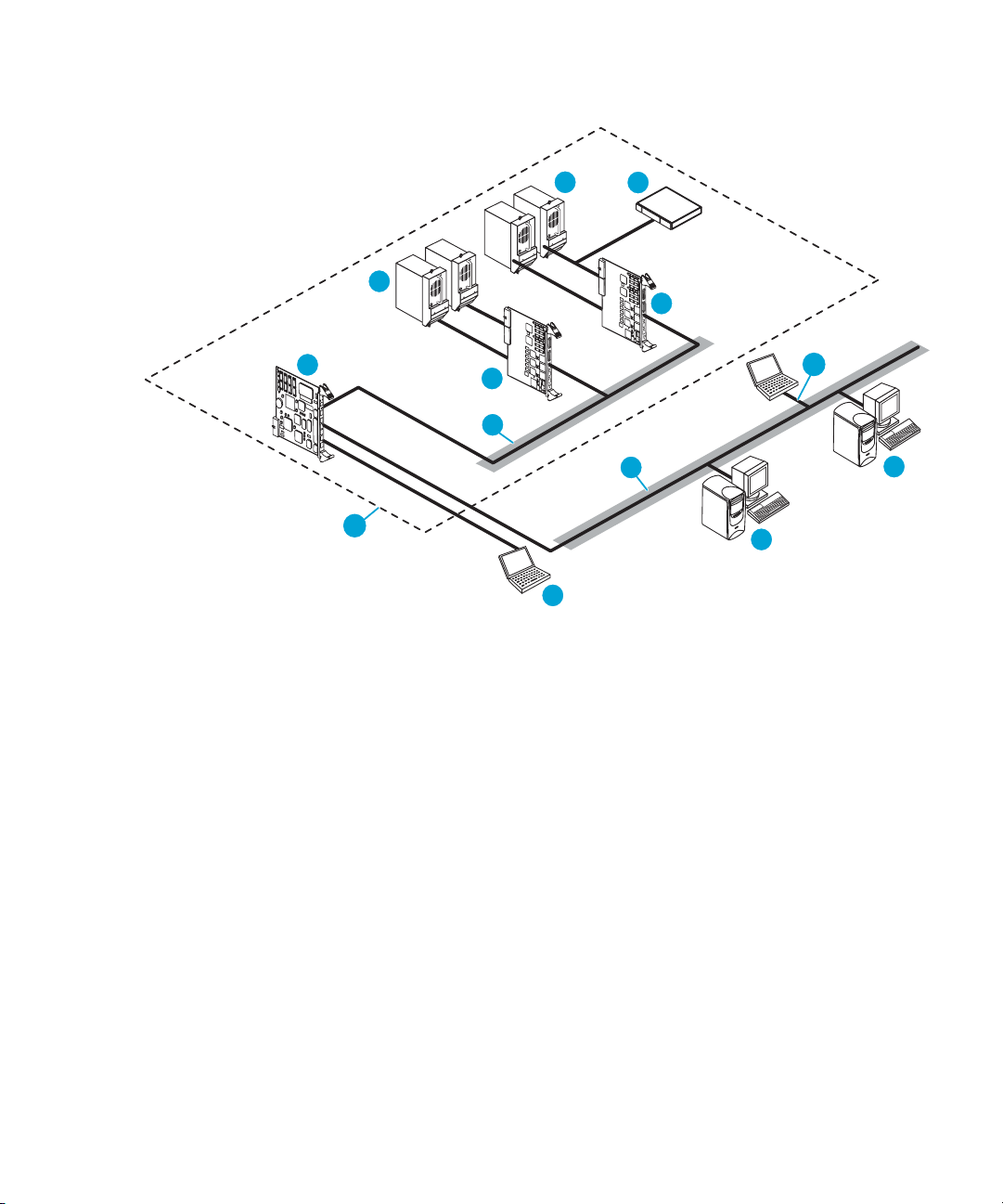
Figure 1, Figure 2, and Figure 3 show how the different UIs communicate with the Interface
Manager card in the various libraries.
1
1
4
11
3
5
10
2
6
Figure 1 Network configuration for ESL9000 Series tape libraries
3
9
8
7
10676
1
Drives
3
FC interface controllers (up to 4)
5
Internal network
7
Management station with Command View TL
9
Telnet connection
11
Library boundary
Interface Manager and Command View for Tape Libraries Software user guide 15
2
Robot
4
Interface Manager card
6
External network
8
Remote web browser connected to
management station via http
10
Serial CLI via RS-232 connection
Page 16
1
1
3
4
5
12
10
11
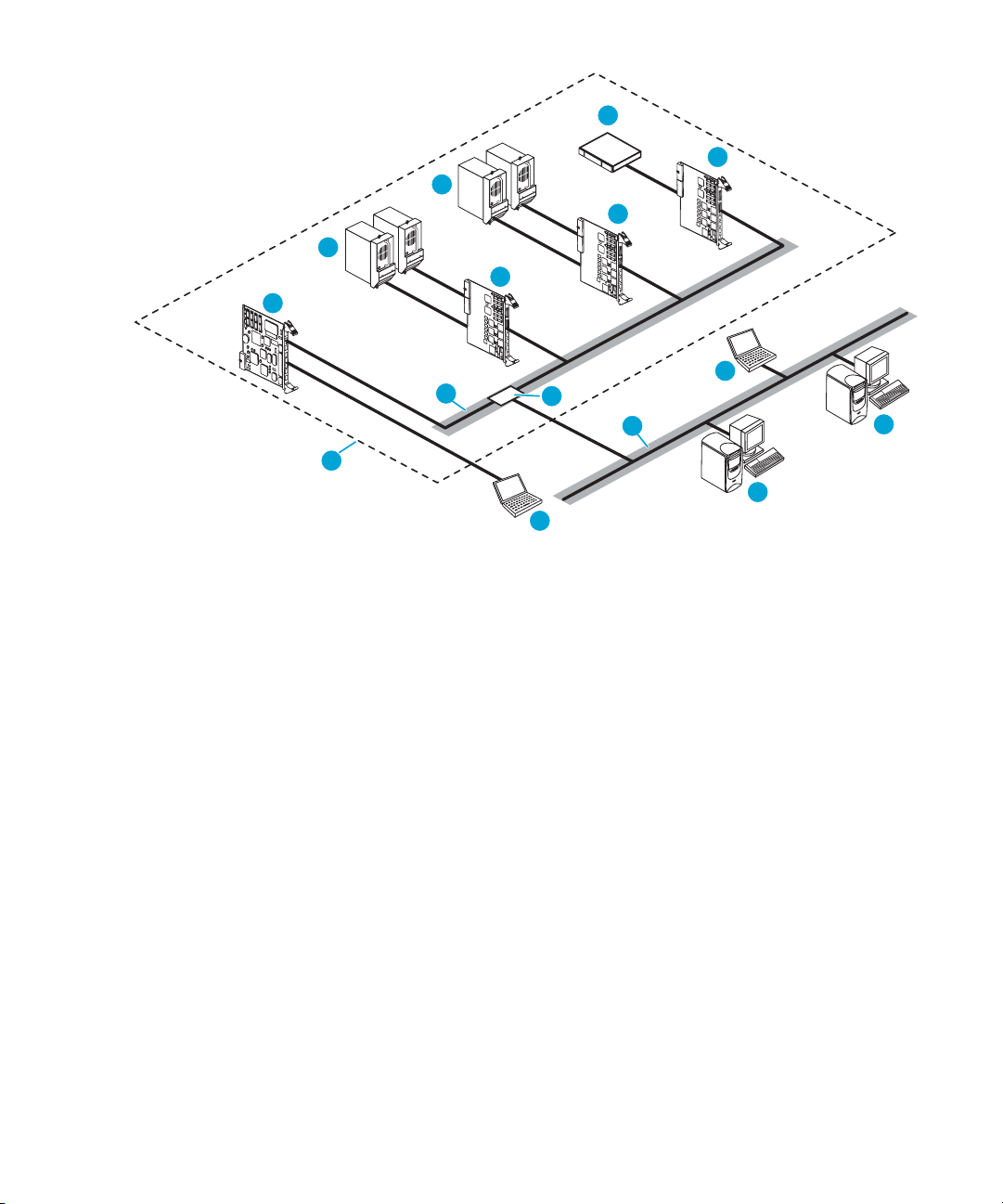
Figure 2 Network configuration for ESL E-Series libraries
2
3
3
9
6
7
8
10675
1
Drives
3
FC interface controllers (up to 4)
5
Internal network
7
Management station with Command View TL
2
Robot
4
Interface Manager card
6
External network
8
Remote web browser connected to
management station via http
9
Telnet connection
11
Serial CLI via RS-232 connection
Introduction16
10
Library cabinet controller
12
Library boundary
Page 17

9
1
3
4
2
5
12
Figure 3 Network configuration for EML E-Series libraries
1
Hosts
3
e2400-FC 2G (or 4G) interface controller (up
2
4
to 4)
5
HP Ultrium tape drives (up to 16)
7
Robot
9
Serial connection
11
Management station
6
8
10
12
10
11
6
7
8
10438
Fibre Channel switch
Interface Manager card
Library robotics controller
Operator control panel
Telnet connection
Library boundary
Interface Manager and Command View for Tape Libraries Software user guide 17
Page 18
External features overview
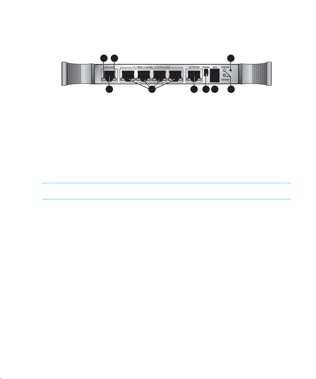
Figure 4 identifies the I/O components of the Interface Manager card.
1 2 3 54 6
Figure 4 Interface Manager faceplate
789
Cascade in back-end Ethernet port
1
3
Front-end Ethernet port (to LAN)
5
Auxiliary RJ-11 serial connector (not used)
7
Reset button
9
Green link activity LED
2
Private Ethernet ports to FC interface
controllers
4
Serial port
6
Board status LEDs
8
Green link speed LED
NOTE: For an explanation of the various LED states, see Troubleshooting.
Introduction18
Page 19

2 Command View for Tape Libraries Software
Overview
HP StorageWorks Command View for Tape Libraries Software (Command View TL) provides a
browser-based GUI for remote management and monitoring of your Interface Manager card
through a LAN. Command View TL is the preferred user interface for controlling the Interface
Manager card. In conjunction with the Interface Manager card, Command View TL provides the
following:
• Configuration and management of the Interface Manager card and FC interface controllers
• Management of the entire library system
• Hardware inventory and identity information
• Status information for connected hardware
• Error reporting and comprehensive error logs
• Firmware management
• License management
Command View TL is installed on the management station and communicates with the Interface
Manager card through the LAN. The management station processes information from the Interface
Manager card and hosts the Command View TL GUI. You can access Command View TL, either
from the management station directly or through any client on the LAN, by using a browser-based
GUI interface. Multiple Command View TL GUI clients can be open simultaneously across the LAN,
and multiple ESL Series libraries can be managed through the Command View TL software.
NOTE: Prior to version 1.5, Command View for Tape Libraries Software was called Command
View ESL.
Prerequisites
For servers, Command View TL requires a management station (server) with a minimum of:
• Pentium IV 1.6-GHz, 512-MB RAM.
• 10/100 Base-T network card (a static IP address is recommended).
• Microsoft® Windows® 2000 Professional or Server edition SP3, Windows XP Professional.
For clients, Command View TL requires the following:
• Microsoft Internet Explorer 6.0 SP1 or later, or Netscape Navigator 6.2 or later. Ensure that
Java™ support is enabled in the browser.
• An Internet connection is recommended so that Command View TL can receive firmware and
software release information automatically from the HP Support web site.
Interface Manager and Command View for Tape Libraries Software user guide 19
Page 20

Installing Command View TL
NOTE: If you are upgrading from a previous version of Command View TL (Command View ESL
prior to version 1.5), follow the procedure below to install the new version over the old version. All
previous settings (device list, support tickets, proxy settings and so forth) are migrated during the
upgrade.
1. Insert the Command View TL software CD into the CD-ROM drive of the designated
management station.
2. If autorun is disabled on the CD-ROM drive, locate and double-click setup.exe on the CD.
3. Follow the instructions on the window to complete the installation.
Command View TL is essentially a web server that hosts a GUI interface to web clients. Command
View TL runs on the management station as a service. By default, this service starts automatically
whenever the management station is booted, and runs invisibly in the background. In most cases,
the default installation settings are adequate.
If you need to stop Command View TL from running on the management station, use the Services
applet that is included with Windows. To access the Services applet, select Start > Settings >
Control Panel > Administrative Tools > Services and locate the Command View TL service in the list.
Use the Services applet to start and stop services, and to set whether the service is started
automatically when the computer is booted. See the online help that comes with the Services applet
for more information.
Starting Command View TL
To start Command View TL, open your browser, either on the management station or on a client
machine on the LAN, and enter the following URL in the address field:
http://<hostname>:4095/
(where <hostname> is the IP address or network name of the management station. If you are
starting Command View TL on the management station itself, you can substitute localhost for the
hostname).
Alternatively, you can start Command View TL from the Windows Start button:
Start > Programs > hp Command View TL > Command View TL
If the Java Runtime Environment (JRE) plugin is not already installed on your computer and you are
using a Windows OS, Command View TL attempts to download and install it for you. If you are
prompted to install the JRE plugin, click OK and follow the instructions on the window. If you are
using a non-Windows OS, you are instructed how to download and install the JRE plugin. If the JRE
plugin is not available, then Command View TL will not run on that machine.
Command View for Tape Libraries Software20
Page 21
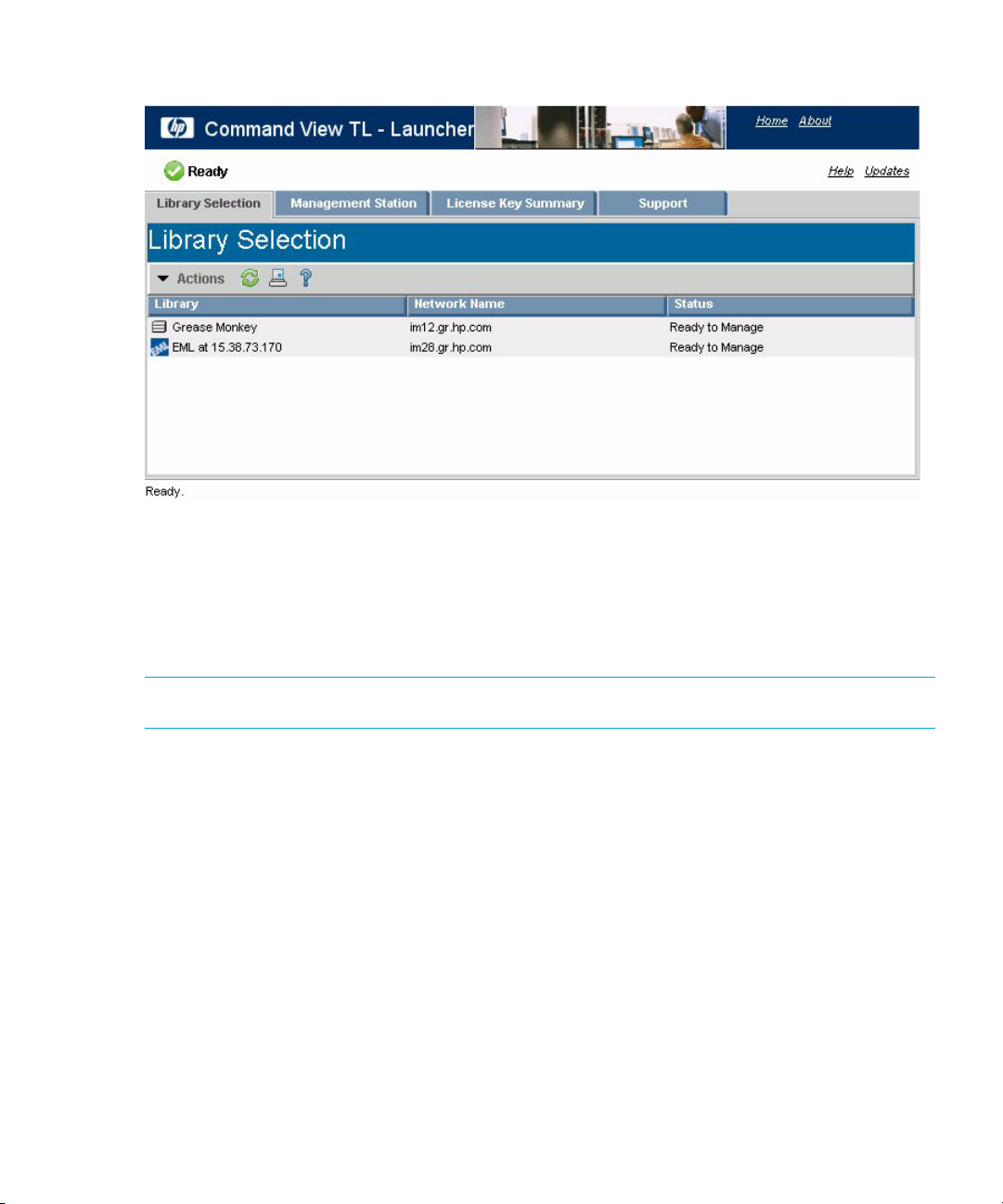
After the JRE is successfully installed, the Command View TL Launcher window is displayed.
Figure 5 Command View TL Launcher window
Verifying connectivity with the Connectivity Check feature
Command View TL manages tape libraries by communicating with the Interface Manager card
installed in each library. The Connectivity Check feature performs a quick check to verify that the
management station can communicate with the Interface Manager card in the selected library.
NOTE: The Connectivity Check feature is available for ESL and EML libraries only.
To use the Connectivity Check feature:
1. Select the library to check.
2. Select Actions > Connectivity Check to open the Connectivity Check dialog box.
3. The Connectivity Check feature performs the test and displays the results. If a problem was
encountered, the dialog box provides information to help you troubleshoot and resolve the
problem.
4. When you are finished, click Finish to close the dialog box. If a problem was encountered,
perform the troubleshooting steps, and then run the Connectivity Check feature again.
Interface Manager and Command View for Tape Libraries Software user guide 21
Page 22

Using the Launcher window
The Launcher window is the launching point for all Command View TL operations. A status indicator
in the top left section of the window, just above the menu bar, shows the status of the management
station and whether or not communication has been established between the client browser and the
management station. On other windows, this status indicator shows the status of the currently
selected library.
The Launcher window has the following tabs:
• Library Selection tab—Displays a list of libraries and virtual tape libraries that can be managed
by Command View TL. You can add or delete libraries from this list, or select a library to
manage.
• Management Station tab—Allows you configure the network settings of the management station.
• License Key Summary tab—Provides a convenient way to track and safely store any additional
license keys you have purchased for use with ESL or EML tape libraries.
• Support Tickets tab—Lists all of the support tickets generated by Command View TL.
Navigating Command View TL
Many windows are divided vertically into two panels. The left panel contains a list or a tree view
showing a hierarchical structure. The right panel displays further information about items selected in
the left panel.
The currently selected library is indicated in the drop-down box below the main menu bar. You can
use this drop-down box to change the currently selected library at any time.
Some windows show data in a columnar format. Depending on the data being displayed, you
might be able to drill down to more detailed information by:
• Double-clicking an item in the list.
• Right-clicking an item in the list, and then selecting an item on the context menu.
• Selecting one or more items in the list, and then selecting an item on the Actions menu.
Command View for Tape Libraries Software22
Page 23

Figure 6 Example of a typical window showing the two-panel format and columnar data
Most windows have an Actions button that displays a menu of actions (the Actions menu) that you
can perform from that window or on the selected item. Menu items in bold type show the default
action for that window or selected item. Double-click the item to perform the action or right-click an
item to display a context menu that duplicates some or all of the menu items in the Actions menu.
CAUTION: Use the various tabs, menus, and buttons throughout the program to navigate. Do not
use the browser navigaton buttons. Doing so may cause loss of configuration data entered on a
window.
Command View TL uses various toolbar buttons to perform different tasks. These buttons may or may
not be available depending on the window you are on. Table 2 lists these buttons and a description
of the action performed. At any time, you can click the Home link in the top right corner of the
screen to return to the Launcher window.
Interface Manager and Command View for Tape Libraries Software user guide 23
Page 24
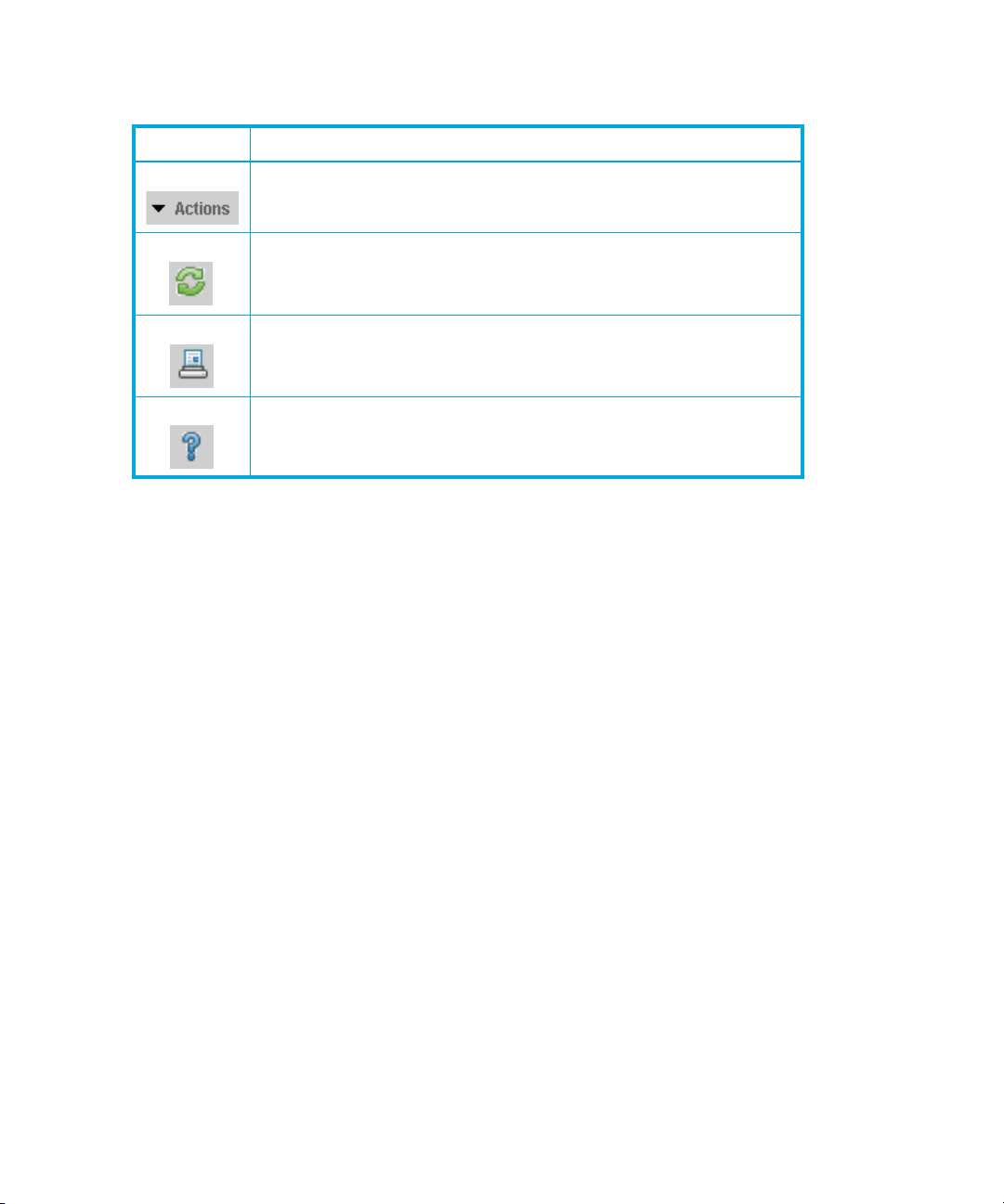
Table 2 Toolbar buttons
Button Description
Actions—Displays a menu of available actions for the current
window or selected item(s).
Refresh—Refreshes the data on the current window.
Print—Opens the Print dialog box and lets you print the data on the
current window to the selected printer.
Help—Opens a help topic associated with the current window.
In addition to the tabs and buttons found throughout the program, Command View TL also has a
menu bar. These menu items basically duplicate the functionality of the buttons shown in Table 2
and do not require further explanation.
Command View for Tape Libraries Software24
Page 25

Device numbering conventions
In some instances, Command View TL numbers devices differently than they are numbered on the
ESL tape library front panel. For example, if the library contains eight drives, the ESL9000 Series
library front panel refers to those drives as drive 0 through 7. Command View TL refers to the same
drives as drive 1 through 8.
Table 3 shows the device numbering conventions used by Command View TL and by the ESL tape
library front panel (when applicable).
Table 3 Device Numbering Conventions
Device Command
View TL
Drives One-based Zero-based One-based One-based
Drive clusters n/a n/a Zero-based * n/a
Slots One-based Zero-based n/a One-based
FC interface controllers One-based n/a n/a One-based
FC host port numbers Zero-based** n/a n/a n/a
SCSI bus numbers Zero-based** n/a n/a n/a
NOTE: * Drive clusters in the ESL E-Series libraries are zero-based, although they are not referred
to from the front panel of the library.
NOTE: ** The zero-based numbering of the FC host ports and SCSI busses corresponds to the
numbers that are printed on the actual hardware.
ESL9000 Series
front panel
ESL E-Series
front panel
EML E-Series
front panel
Interface Manager and Command View for Tape Libraries Software user guide 25
Page 26

Initial configuration steps
After you have successfully installed the Interface Manager card and started Command View TL:
1. Set the administrative password for Command View TL. See Administrative password.
2. Verify that proxy settings for the management station are correct. See Network settings.
3. Add all libraries that will be monitored to Command View TL. See Adding or removing a library.
4. Add the license key for Command View TL and any additional features that you have purchased.
See License Key Summary tab.
5. Configure the following for each library. See Configuring a library.
•Library name
• System date
• System time
•Time zone
• System contact name
• System contact phone number
• System contact pager number
• System contact e-mail address
•System location
• System asset number
6. (Optional) Configure library partitions. Library partitions are configured using Secure Manager.
Therefore, this step requires a Secure Manager license. Partitioning the library erases all host
access configuration settings. See Partitioning a library.
7. Configure host access (Secure Manager). By default, Secure Manager prevents all hosts from
accessing the library. You must configure Secure Manager to allow host access to the library.
See Configuring access for a host HBA.
Other common Command View TL functions
The following list provides quick links to several of the most common functions performed by
Command View TL:
• Adding or removing a library
• Configuring a library
• Configuring the Fibre Channel interface controllers
• Monitoring device status
• Viewing the event log
• Viewing inventory of the library
• Updating firmware
• Using the License Manager
• Media management
Command View for Tape Libraries Software26
Page 27

Adding or removing a library
You must add all libraries that will be monitored or accessed by Command View TL. The library IP
address can be set through the Interface Manager card serial interface or cascade port or, on ESL
E-Series libraries, through the library Operator Control Panel (OCP).
NOTE: For more information about getting or setting the library IP address, ESL9000 Series users
see “Getting or Setting the Interface Manager IP Address” in the HP StorageWorks Interface
Manager and Command View TL installation guide. ESL E-Series users should see the HP
StorageWorks ESL E-Series tape library unpacking and installation guide.
Command View TL also supports the HP StorageWorks 6000 Virtual Library System (VLS) and HP
StorageWorks MSL libraries. MSL and VLS libraries can be added the same way as a regular
library (see below). Command View TL automatically displays a different icon on the Launcher
window for these libraries. If you attempt to manage an MSL or VLS library from Command View TL,
a separate utility is opened in a separate browser window. See the documentation provided with
each product for more information on managing these libraries.
Libraries can be added manually, or by using the Library Discovery wizard.
Using the Library Discovery wizard
The Library Discovery wizard can discover all of the HP StorageWorks libraries connected to the
same subnet as the management station. Discovered libraries are displayed with an icon
corresponding to the type of library. VLS libraries that are not already configured can be configured
using the Library Discovery wizard. However, non-VLS libraries must be configured manually. The
Library Discovery wizard lets you choose which libraries to add to the Launcher window.
NOTE: At the time of release, version 1.6 of Command View TL may not fully support discovery of
certain libraries. If your library is not discovered, you must add it manually.
To use the Library Discovery wizard:
1. On the Launcher window, select Actions > Library Discovery Wizard.
2. On the welcome page, click Next. On page 1 of the wizard, the discovery process takes place.
After a short time, the wizard displays a list of the discovered libraries.
3. Click Next. If any VLS libraries were discovered that require configuring, you can configure them
on page 2 of the wizard. To configure a VLS library:
NOTE: If you do not want to configure any libraries at this time, click Next to advance to the
last page of the wizard.
Interface Manager and Command View for Tape Libraries Software user guide 27
Page 28

a. Select the library to configure. If you are unsure which devices comprise the VLS library, click
Beacon. The Beacon function flashes the LEDs on the front of the corresponding unit for the
amount of time you specify.
b. Click Configure. In the Network Settings dialog box, make the required configuration
changes, and then click OK.
4. On the last page of the wizard, select the libraries that you want to add to the Launcher window.
You can us e the Select All and Clear All buttons to speed up the process. After selecting the
required libraries, click Finish to add the libraries to the Launcher window and exit the wizard.
Manually adding or removing a library
To manually add a library:
1. From the Library Selection tab of the Launcher window, select Actions > Add Library to display
the Add Library dialog box.
2. Enter the management IP address (or hostname of the Interface Manager card) of the library or
virtual library to be added, and then click OK.
To remove a library:
1. Select the library or virtual library to be removed.
2. Select Actions > Remove Library.
3. On the Confirm Library Removal dialog, click Yes to confirm the deletion.
Command View for Tape Libraries Software28
Page 29

Configuring a library
NOTE: The following procedure only applies to physical tape libraries. Double-clicking a virtual
tape library opens Command View VLS—a separate utility. See the documentation provided with
Command View VLS for more information on managing virtual tape libraries.
1. From the Library Selection tab of the Launcher window, double-click the library to configure.
2. Click the Configuration tab.
3. To configure the library properties:
a. Select the Library Properties item in the tree view to display properties for the selected
library.
The Library Properties window displays the following groups of information:
•Library Name
• System Date/Time
•Contact Information
b. Select Edit Library Name, Edit System Date/Time, or Edit Contact Information as needed
from the Actions menu.
A dialog box is displayed allowing you to edit the desired properties.
c. Make the required changes, and then click OK. The library properties are stored in the
memory of the Interface Manager card.
4. To configure the network (TCP/IP) settings of the library:
a. Select the TCP/IP item in the tree view to display the TCP/IP configuration window.
The following information pertaining to the selected Interface Manager card is displayed
(only the network settings can be edited):
•Network Settings
•Hostname
• Address configuration
• IP address
•Subnet mask
•Gateway
• DNS domain name
• DNS addresses
•MAC Settings
• MAC address
•Link selection
Interface Manager and Command View for Tape Libraries Software user guide 29
Page 30

b. If necessary, obtain the required network settings from your network administrator.
c. Select Actions > Edit Network Settings to display the Network Settings dialog box.
d. Make the changes as required, and then click OK.
Configuring the Fibre Channel interface controllers
1. On the Library Selection tab of the Launcher window, double-click the library hosting the FC
interface controllers to be configured.
2. Click the Configuration tab.
3. Select the Connection Properties item under Interface Settings in the tree view to display the
Connection Properties window.
The first column of this window shows the FC interface controllers that are connected to the
Interface Manager card. The FC host ports are shown under their respective FC interface
controller.
4. Select an FC host port. In Automatic mode, it does not matter which FC host port is selected
because the changes you make apply to all FC host ports. In Manual mode, each FC host port
can be configured independently.
5. Select Actions > Edit Port Connection Settings to display the Port Connection Settings dialog box.
6. Set the Port Connection Type to one of the following:
• Fabric (SAN) Attach—Use this connection type when connecting all FC host ports to an FC
switch.
• Direct Attach—Use this connection type when connecting all FC host ports to a Host Bus
Adapter (HBA) on a backup server.
7. Set the Port Speed. Use the maximum speed that your SAN infrastructure supports.
8. Click OK to save the changes.
Monitoring device status
1. On the Library Selection tab of the Launcher window, double-click the library that you want to
monitor.
2. Click the Status tab.
3. To view a comprehensive health summary of the library and all its component devices, select the
Health Summary item in the tree view.
The first column of the health summary displays each component of the library in a hierarchical
tree view. Each component is shown with a green, yellow, or red status symbol that allows you to
see if any components need attention. The second column describes the health of the
component, and the third column provides additional information that may be useful if there is a
problem with the component.
Command View for Tape Libraries Software30
Page 31

NOTE: The Health Summary window is automatically updated whenever the status of the library
changes.
4. To view detailed status of an individual device, in the Component Status group of the tree view,
click the icon for the component.
Relevant information for that component is displayed in the right panel. The information
displayed varies depending on the component selected. In the right panel, double-click a
component to display component properties.
Viewing the event log
1. On the Library Selection tab of the Launcher window, double-click the desired library.
2. Click the Status tab.
3. Click the Event Log item in the tree view to display the event log.
The following information is displayed for each event:
• Timestamp—Time that the event was recorded.
• Event Description—Brief description of the event.
• Source—Device that triggered the event.
Interface Manager and Command View for Tape Libraries Software user guide 31
Page 32

• Severity—Displays one of the following icons indicating the type of the event:
• Critical—May prevent normal operations of the library and must be addressed
immediately
• Warning—Does not require immediate attention but should be addressed as soon
as possible
• Information—Presents information the user should be aware of but does not require
immediate attention
4. Double-click an event to display the event in a dialog box. The dialog box displays the same
information as shown above.
Viewing inventory of the library
1. On the Library Selection tab of the Launcher window, double-click the desired library.
2. Click the Status tab.
3. Select the Inventory item in the tree view to display the Inventory window.
For more information about the Inventory window, see Inventory.
Updating firmware
1. On the Library Selection tab of the Launcher window, double-click the desired library.
2. Click the Support tab.
3. Select the Firmware Update item in the left panel to display the Firmware Update window.
The first column of the Firmware Update window displays the Interface Manager card and all FC
interface controllers, robotics, and drives that are connected to the Interface Manager card. The
second column displays the current firmware revision of the corresponding device, and the third
column indicates whether this is the correct firmware revision or a mismatch for the
corresponding device.
Command View for Tape Libraries Software32
Page 33

Figure 7 Firmware Update window
Command View TL provides a convenient Firmware Update wizard enabling you to easily manage
the firmware revisions of all the components in your library.
CAUTION: Ensure that all applications that try to access the library or drives are shut down until
the firmware update is completed. Do not interrupt the firmware update process. Stopping this
program or powering down the device during the update could cause the device to be inoperable
and require physical repair.
Interface Manager and Command View for Tape Libraries Software user guide 33
Page 34

4. Select Actions > Launch Firmware Update Wizard to launch the Firmware Update wizard.
5. Decide whether to allow firmware downgrades. By default, firmware downgrades are not
allowed, meaning that only newer firmware versions can be uploaded to your hardware.
If you need to allow firmware downgrades (for example, if a newer firmware version is causing
problems and you want to revert back to an older version that was known to work properly),
select Allow Firmware Downgrades.
6. Choose one of the following options:
• Use HP web services to determine optimum updates for the library—This option causes
Command View TL to check the HP Support web site for all compatible firmware files. If you
select Ensure firmware information is up to date (recommended), Command View TL
downloads the latest list of supported hardware with current firmware revisions and saves it
locally on the management station. This list is updated every 24 hours on the HP Support
web site, so checking this option ensures that Command View TL is up-to-date on all the latest
firmware revisions.
a. Click Next to display the Device Selection window.
b. Proceed to step 7.
Command View for Tape Libraries Software34
Page 35

• Choose local firmware file(s)—This option lets you choose firmware files that are stored
locally.
a. Click Add to browse to the firmware file(s). To select multiple files in the same directory,
hold down Ctrl while selecting the files. Click Select to return to the Firmware Selection
Method window.
b. Click Next to display the Device Selection window.
7. Select the device(s) to be updated in the left column. The current revision for each device is
displayed in the middle column.
8. For each selected device, select the appropriate firmware revision from the drop-down box in the
right column.
9. Click Next to display the Firmware Update Summary window.
10.Confirm the firmware update selections and select I understand that this update will cause
currently running backups to fail.
11.Click Next to display the Firmware Update Progress window. This window displays the progress
of the firmware update. When complete, a dialog box displays the status of the update. Click
OK to close the dialog box.
12.Click Finish to exit the wizard.
Using the License Manager
To access the License Manager, click the License Key Summary tab on the Launcher window. See
License Key Summary tab for more information.
Interface Manager and Command View for Tape Libraries Software user guide 35
Page 36

Library Selection tab
The Library Selection tab displays a list of libraries and virtual tape libraries that can be managed
by Command View TL. From this tab, you can add and delete libraries or select a library to be
managed. Selecting a library to manage lets you drill down to the individual components or other
aspects of the library.
Adding and removing libraries
You must add all libraries that will be monitored or accessed by Command View TL. Command
View TL supports the HP StorageWorks 6000 Virtual Library System (VLS) and HP StorageWorks
MSL libraries. MSL and VLS libraries can be added the same way as a regular library (see below).
Command View TL automatically displays a different icon on the Launcher window for these
libraries. If you try to manage an MSL or VLS library from Command View TL, a separate utility is
opened in a separate browser window. See the documentation provided with each product for more
information on managing these libraries.
Libraries can be added manually, or by using the Library Discovery wizard. For more information
about the Library Discovery wizard, see Using the Library Discovery wizard.
To manually add a library:
1. From the Library Selection tab of the Launcher window, select Actions > Add Library to display
the Add Library dialog box.
2. Enter the management IP address (or hostname of the Interface Manager card) of the library or
virtual library to be added, and then click OK.
NOTE: For each library, the status column displays the name of the management station that is
managing the library.
To remove a library:
1. Select the library to be removed.
2. Select Actions > Remove Library.
3. In the Confirm Library Removal dialog, click Yes to confirm the deletion.
Managing libraries
To manage a library:
NOTE: The following procedure only applies to physical tape libraries. Double-clicking a virtual
tape library opens Command View VLS—a separate utility. See the documentation provided with
Command View VLS for more information on managing virtual tape libraries.
1. Select the library to manage.
2. Select Actions > Manage Library. Alternatively, you can right-click the desired library and select
Manage Library.
Command View for Tape Libraries Software36
Page 37

When you select a library to manage, the currently selected library is displayed in a drop-down box
immediately below the main menu bar. Change the currently selected library at any time by
selecting a different library from this drop-down box.
NOTE: If you select a library to manage that is already managed by another management station
on which Command View TL is installed, a dialog box is displayed asking if you want to reclaim the
library.
When a library has been selected for management, a new window is displayed with the following
five tabs:
• Identity tab—Displays summary information about the currently selected library.
• Status tab—Displays a tree view in the left panel showing a hierarchical view of the library and
its components. The right panel displays status information about the selected item. On the Status
tab, you can also view a health summary of the entire library, view an event log, or view the
inventory of the library.
• Configuration tab—Allows you to configure library properties, interface settings, network
settings, and licensed capacity (for those libraries that support it). You can also partition the
physical library into multiple logical libraries (using Secure Manager), configure HP
StorageWorks Direct Backup Engine, and configure HP StorageWorks Secure Manager
(assuming the appropriate licenses have been purchased for those features).
• Operations tab—Provides a convenient way to move media and to reboot the library or
individual components of the library.
• Support tab—Provides useful resources for finding support. On the Support tab, you can also
update firmware, generate support tickets, and restore factory defaults for the Interface Manager
card and selected interface controllers.
Identity tab
The Identity tab displays summary information and a photo of the currently selected library. This tab
is useful when you need to quickly find information pertaining to a library, such as the number of
drives or interface controllers it contains. Another use for the Identity tab is finding the library serial
number, which is required when ordering any of the optional, licensable features of the ESL Series
library (see Advanced features for more information about additional licensable features).
Status tab
The Status tab uses the traditional two-panel interface to show status information about the selected
library. The left panel displays a hierarchical tree view of the selected library, and the right panel
displays information pertaining to the item selected in the left panel.
The currently selected library is indicated in the drop-down box just below the main menu bar. You
can change the currently selected library at any time by selecting a different library from this
drop-down box.
Interface Manager and Command View for Tape Libraries Software user guide 37
Page 38

The Status tab displays several types of information that can be accessed from the tree view:
• Health summary
• Cabling view
• Component Status
• Event log
• Inventory
Health summary
Select the Health Summary item in the tree view to display a comprehensive health summary of the
selected library in the right panel. The first column of the health summary displays each component
of the library in a hierarchical tree view. Each component is shown with a green, yellow, or red
status symbol that enables you to see if any components need attention. The second column
describes the health of the component, and the third column provides additional information that
may be useful if there is a problem with the component.
Figure 8 Health Summary window
Command View for Tape Libraries Software38
Page 39

Cabling view
Devices are displayed hierarchically by physical connection in the Cabling View window, which
shows the same information as the Health Summary window.
Figure 9 Cabling View window
Component Status
The Component Status function displays the current status of the following library components
individually:
• Library
• Robotics
• Drives
• Interface Controllers
• Interface Manager
Click the icon for the component you want to view status of in the tree view in the left panel.
Relevant information for that component is displayed in the right panel. The information displayed
varies depending on the component selected.
NOTE: Double-click a component in the right panel to display properties of the component.
Interface Manager and Command View for Tape Libraries Software user guide 39
Page 40

Event log
The following information is displayed for each event in the event log:
• Timestamp—Time that the event was recorded.
• Event Description—Brief description of the event.
• Source—Device that triggered the event.
• Severity—Displays one of the following icons indicating the type of the event:
• Critical—May prevent normal operations of the library and must be addressed
immediately.
• Warning—Does not require immediate attention but should be addressed as soon as
possible.
• Information—Presents information the user should be aware of but does not require
immediate attention.
Double-click an event to display the event in a dialog box. The dialog box displays the same
information as shown above.
Inventory
The Inventory window shows how tape cartridges are distributed throughout the library.
Figure 10 Inventory window
The Location column displays all the possible locations for tape cartridges in tree view format. For
simplicity, all of the drives are grouped under the Drives folder, mailslots are grouped under the
Mailslots folder, and slots are grouped in the Slots folders. Depending on your library, slots are
Command View for Tape Libraries Software40
Page 41

grouped into the Slots folders either in groups of 40, or by the location of the slots in the library (for
example, back wall, upper-left panel, and so forth). By default, the Drives folder is expanded, and
all of the Slots folders are collapsed. Click the plus sign (+) to expand a group or the minus sign (-)
to collapse a group.
The Status column indicates whether the corresponding location is full (contains a tape cartridge) or
empty. If the corresponding location is a group folder, the Status column displays how many
locations in that group are full. In the example shown in Figure 10, the folder containing slots 1
through 40 shows that 15 slots are full. To see exactly which slots are full, click the plus sign (+) to
expand the group. Each individual slot is then displayed underneath the folder, and the Status
column displays Full or Empty for each slot.
For each full location, the Barcode column shows the unique barcode identifier for the tape
cartridge in that location. To quickly locate a particular tape cartridge:
1. Select Actions > Find Barcode to display the Find Barcode dialog box.
2. Enter the identifier for the tape cartridge you are searching for.
3. If you want the search to be case sensitive, select the Match case check box.
4. Click OK to perform the search.
If the cartridge you are looking for is found, it is highlighted in the display. If the cartridge is part of
a collapsed group, the group is automatically expanded.
The Partition column indicates which partition (if any) the drive, slot, or mailslot is in, along with its
position in the partition. For example, if you have created a partition called Windows and added
drives five and six to the list of drives in that partition, the Partition column would display Windows,
Drive 1 for drive five and Windows, Drive 2 for drive six. The Partition column displays None for
non-partitioned items.
Configuration tab
The Configuration tab uses the traditional two-panel interface to show configuration settings for the
selected library. The left panel displays a hierarchical tree view of the selected library, and the right
panel displays information pertaining to the item selected in the left panel.
CAUTION: Some configuration changes require a reboot of the Interface Manager card. If a
reboot is required, a dialog box is displayed allowing you to confirm or cancel the action. To
prevent data loss, ensure that all backup jobs are complete before making any configuration
changes that require a reboot.
The currently selected library is indicated in the drop-down box just below the main menu bar. You
can change the currently selected library at any time by selecting a different library from this
drop-down box.
The Configuration tab displays several types of information that can be accessed from the tree view:
• Library properties
• Interface settings
Interface Manager and Command View for Tape Libraries Software user guide 41
Page 42

• Host access (Secure Manager)
• Partitioning
• Direct backup
• Network settings
• Licensed Capacity Panel Upgrade for ESL E-Series feature
• Save/Restore feature
Library properties
Select the Library Properties item in the tree view to display properties for the selected library. The
Library Properties window displays the following groups of information:
• Library Name
• System Date/Time
• Contact Information
To edit the library properties:
1. Select Edit Library Name, Edit System Date/Time, or Edit Contact Information as needed from
the Actions menu. A dialog box is displayed, allowing you to edit the desired properties.
2. Make the required changes and click OK. The library properties are stored in the memory of the
Interface Manager card.
Interface settings
The Interface Settings consist of two items:
• Interface Manager mode
• Connection properties
• WWN retention
Interface Manager mode
The Interface Manager mode setting controls the behavior of the Interface Manager card and
dictates how the FC interface controllers are configured.
In Automatic mode, the Interface Manager card ensures that the library is configured correctly and
consistently across all FC interface controllers. In the event of a field-replaceable unit (FRU)
replacement, advanced logic is enabled to maintain consistent firmware revisions and to present a
consistent device map to backup servers.
In Manual mode, each FC interface controller is configured independently. The Interface Manager
card does not provide consistency checking or FRU replacement logic.
CAUTION: HP strongly recommends that you leave the Interface Manager mode set to the default
setting of Automatic. Using Manual mode increases the risk of making serious configuration errors
and causing hardware conflicts that can severely disrupt the normal operation of the library.
Command View for Tape Libraries Software42
Page 43

To change the Interface Manager mode:
1. Select the Interface Manager Mode item in the tree view to display the Interface Manager Mode
window.
2. Select Actions > Edit Interface Manager Mode to display the Interface Manager Mode dialog
box.
3. Change the mode as required, and then click OK.
Connection properties
Select the Connection Properties item in the tree view to display the Connection Properties window.
This window displays connection properties for the FC interface controllers. The first column of this
window shows the FC interface controllers that are connected to the Interface Manager card. The
FC host ports are shown under their respective FC interface controller. The remaining columns
display the following information pertaining to the FC host ports:
• World Wide Name
• Connection Type
• Port Mode
• Hard AL-PA
• Speed (Gbps)
Only the connection type and speed of the ports can be set manually. The remaining items are
configured automatically by the Interface Manager card. When running in Automatic mode, if you
make changes to one FC host port, those changes are applied to all the FC host ports on all the FC
interface controllers in the library. In Manual mode, changes apply only to the selected FC host port.
To edit the FC host port settings:
1. Select any FC host port. It does not matter which FC host port is selected because the changes
you make apply to all FC host ports.
2. Select Actions > Edit Port Connection Settings to display the Port Connection Settings dialog box.
3. Set the Port Connection Type to one of the following:
• Fabric (SAN) Attach—Use this connection type when connecting all FC host ports to an FC
switch.
• Direct Attach—Use this connection type when connecting all FC host ports directly to a Host
Bus Adapter (HBA) on a backup server.
4. Set the Port Speed. Use the maximum speed that your SAN infrastructure supports.
5. Click OK to save the changes.
Interface Manager and Command View for Tape Libraries Software user guide 43
Page 44

WWN retention
The Interface Manager card has the ability to retain the World Wide Names (WWN) of installed
interface controllers. The WWN retention policy controls the behavior of the Interface Manager and
dictates the World Wide Names for your interface controllers. When this policy is enabled, the
Interface Manager ensures that your interface controllers maintain the same WWN, along with the
host mapping configuration and partitioning configuration, in the event that they require
replacement. This allows your backup configuration to continue unchanged, despite the
replacement. When the WWN retention policy is disabled, each library interface controller
maintains its original WWN. Replacement will change the WWN of the interface controller and
require changes to your backup configuration. Host mapping and partitioning will also need to be
reconfigured.
IMPORTANT: If this feature is not available with your configuration, ensure that you are using
firmware version I170 or greater for the Interface Manager card. Also, make sure that your interface
controllers have the latest available firmware. The Interface Manager card and all interface
controllers must have the correct firmware version or the WWN retention feature will not be
available.
Select the WWN Retention item from the tree view to display the WWN Retention window. The
WWN Retention window displays the current state (enabled/disabled) of the WWN retention
policy, and lists any mismatched interface controllers.
To edit the WWN retention policy:
1. Select Actions > Edit WWN Retention State to display the Edit WWN Retention State dialog
box.
2. Select Enabled or Disabled in the drop down box.
3. Click OK.
Clearing a WWN mismatch
Beginning with version 1.7, the Interface Manager card claims “ownership” of the interface
controllers installed in a library. The MAC address of the Interface Manager card is stored in the
memory of each interface controller, creating an association between the Interface Manager card
and the interface controller(s). If an interface controller that was “owned” by an Interface Manager
card is transferred from one library to another, then the Interface Manager card in the new library
will detect a WWN mismatch. To clear this situation, and to associate the interface controller with
the current Interface Manager card:
1. Select Actions > Clear WWN mismatches. The following warning message is displayed:
Command View for Tape Libraries Software44
Page 45

TIP: When the WWN Retention policy is enabled, moving a configured interface controller from
one library to a previously empty slot in another library may allow a duplicate WWN to exist in the
SAN. The Interface Manager and Command View TL will highlight this possibility, but you will need
to take additional action as noted in this section.
2. Verify that there are no other interface controllers with the same WWN in the SAN. If necessary,
cancel out of the Clear WWN Mismatches dialog, and then use the Connection properties item
under Interface Settings on the Configuration tab to view the WWN of your interface controllers.
See Connection properties for more information. After verifying that there are no duplicate
WWNs in your SAN, repeat step 1 to return to the Clear WWN Mismatches dialog.
NOTE: If a duplicate WWN is discovered, contact HP support.
3. Click OK. The dialog closes, and the interface controller is now “owned” by the Interface
Manager card.
Replacing an interface controller with WWN retention enabled
If you need to replace an interface controller, refer to the appropriate library and interface controller
documentation for information on how to replace the hardware. Some interface controllers are
hot-pluggable. Refer to the interface controller documentation to see if your controller is
hot-pluggable.
Interface Manager and Command View for Tape Libraries Software user guide 45
Page 46

After replacing an interface controller in a library that has WWN retention enabled, all of the
following should happen:
• If an older version of firmware is detected in the replacement interface controller, the Interface
Manager card will immediately update the firmware in the interface controller.
• The Interface Manager card sets the WWN of the replacement interface controller to match the
WWN of the controller that was replaced.
• The Interface Manager card transfers the retained host mapping and partitioning configuration
data to the replacement interface controller.
If the replacement was successful, Command View TL displays the interface controller configured
exactly as it was before. If any of these steps fail, the process aborts and WWN retention is
immediately disabled. The interface controller is listed in Command View TL as a new controller,
and none of the previous configuration data is retained. If this occurs, contact HP support.
Host access (Secure Manager)
Select the Host Access item in the tree view to display the Host Access configuration window. HP
StorageWorks Secure Manager enables advanced security functions to protect your library from
disruptive SAN traffic. Basic Secure Manager functions are enabled in every copy of Command
View TL, but full-featured functionality must be licensed separately. For more information, see
Secure Manager.
Partitioning
Select the Partitioning item in the tree view to display the Partitioning window. From this window,
you can partition the physical library into multiple logical libraries. For more information, see
Partitioning a library.
Direct backup
Select the Direct Backup item in the tree view to display the Direct Backup configuration window.
HP StorageWorks Direct Backup Engine enables fast, serverless backup functionality through the
FC interface controllers and Interface Manager card. Direct Backup must be licensed separately.
For more information, see Direct Backup Engine.
Network settings
The network settings consist of two items:
• TCP/IP
• SNMP alerts
Command View for Tape Libraries Software46
Page 47

TCP/IP
Select the TCP/IP item in the tree view to display the TCP/IP configuration window. The following
information pertaining to the selected library’s Interface Manager card is displayed:
• Network Settings
•Hostname
• Address Configuration
• IP Address
•Subnet Mask
•Gateway
• DNS Domain Name
• DNS Addresses
• MAC Settings
•MAC Address
•Link Selection
Only the network settings can be edited. To edit the network settings:
1. If necessary, obtain the required network settings from your network administrator.
2. Select Actions > Edit Network Settings to display the Network Settings dialog box.
3. Make the changes as required, and then click OK.
SNMP alerts
Select the SNMP Alerts item in the tree view to display the SNMP Alerts window.
Figure 11 SNMP Alerts window
Interface Manager and Command View for Tape Libraries Software user guide 47
Page 48

Simple Network Management Protocol (SNMP) is a well-defined standard of reporting device
information through a network. The Interface Manager card has a built-in SNMP agent that
supports queries to MIB-II in addition to SNMP traps/alerts.
Command View TL lets you change the following common SNMP settings:
• Trap Destinations—IP addresses of hosts or applications that need to receive SNMP alerts/traps
from the Interface Manager card. A trap receiver is an SNMP-enabled machine on the LAN that
decodes and logs SNMP traps. Up to eight trap destinations can be specified.
• Community String—Plain-text community string or password required by SNMP clients to read or
write SNMP MIB values.
To add a new SNMP trap entry:
1. If necessary, obtain the required network settings from your network administrator.
2. Select Actions > Add Trap Entry to display the SNMP Trap Entry dialog box.
3. Enter the Trap Destination and Community String, and then click OK.
To edit an existing trap entry:
1. Select the trap entry to be modified.
2. Select Actions > Edit Trap Entry to display the SNMP Trap Entry dialog box.
3. Modify the Trap Destination and Community String as necessary, and then click OK.
To remove an existing trap entry:
1. Select the trap entry to be removed.
2. Select Actions > Remove Trap Entry.
3. Click Yes in the confirmation dialog box to confirm the deletion.
Licensed Capacity Panel Upgrade for ESL E-Series feature
Certain HP StorageWorks tape libraries allow you to license additional capacity as needed. For
more information, see Using the Licensed Capacity Panel Upgrade for ESL E-Series feature.
Command View for Tape Libraries Software48
Page 49

Save/Restore feature
The Save/Restore feature allows you to save configuration information of the Interface Manager
card and interface controllers. The information saved includes library properties (name, contact
information), connection properties, advanced feature settings (host access, partitioning, licensed
capacity), and SNMP alert settings. A saved configuration basically stores the settings of all the
features on the Configuration tab. It does not save firmware versions or data on tape cartridges.
Figure 12 Save/Restore screen
The Actions menu offers the following choices:
• Save Current Configuration—opens the Save Current Configuration wizard. On the first page,
you can review the current configuration information. On the second page, specify the path
and filename of the configuration file to save. In most cases, the default filename should be
adequate, although you should specify a location to save the file.
• Restore Configuration—opens the Restore Configuration wizard. On the first page, select the
configuration file to restore. On the second page, select the checkbox acknowledging that you
realize that restoring a previous configuration overwrites the current configuration, and then
click Finish. The Interface Manager card reboots with the new settings.
• View Saved Configuration—allows you to select and view the contents of a configuration file.
Operations tab
The Operations tab provides functionality for rebooting individual devices or the library itself, and
for moving media within a library.
Interface Manager and Command View for Tape Libraries Software user guide 49
Page 50

Reboot
Click the Reboot item in the left panel to display the Reboot window. The first column of the Reboot
window displays items representing the library, the Interface Manager card, and all FC interface
controllers that are connected to the Interface Manager card. The second column provides a specific
identifier for each device, and the third column indicates whether or not a reboot is required for the
corresponding device.
CAUTION: Rebooting a device terminates any operations that device might be performing. To
avoid loss of data, ensure that all backup jobs or other operations have completed before
attempting to reboot any device.
NOTE: Rebooting the library can take up to 30 minutes.
To reboot a single device:
1. Select the device to be rebooted.
2. Select Actions > Reboot Selected Component. Alternatively, right-click the item and select Reboot
Selected Device.
3. Confirm that you want to reboot the device in the confirmation warning dialog.
To reboot all devices in the list other than the library:
1. Select Actions > Reboot Interface Manager and All Controllers.
2. Confirm that you want to reboot all the devices in the confirmation warning dialog.
To reboot all devices that require a reboot (that is, all devices that say yes in the Reboot Required
column):
1. Select Actions > Reboot All Required Components.
2. Confirm that you want to reboot all the devices in the confirmation warning dialog.
Command View for Tape Libraries Software50
Page 51

Media management
Click the Media Management item in the left panel to display the Media Management window. The
Media Management window displays three or four columns, depending on whether the library is
partitioned or not.
Figure 13 Media Management window
• Location column—Displays the drives, slots, and mailslots available in the library.
• Status column—Indicates whether the corresponding drive, slot, or mailslot contains media (full
or empty).
• Barcode column—Displays the barcode identifier of the media if media is present in the
corresponding drive, slot, or mailslot.
• Partition column—Displayed only if the library has been partitioned. The column indicates which
partition the corresponding drive, slot, or mailslot has been assigned to, and its position in the
partition. For example, in Figure 13, drive five is shown as being the first drive in partition one.
Moving media requires that you first select the source location (which must be full), and then select a
destination location (which must be empty).
CAUTION: Whenever possible, move media using your backup application. The move media
functionality of Command View TL is provided as an alternate means of moving media if you
encounter a problem with your backup application or with the library. After using Command View
TL to move media, you must re-inventory the library from within your backup application so that the
library and backup application remain synchronized.
Interface Manager and Command View for Tape Libraries Software user guide 51
Page 52

To move media:
1. Do either of the following to launch the Move Media wizard:
•Select Actions > Move Media.
• Right-click the source location and select Move Media.
2. On the first page of the Move Media wizard, select the source location, and then click Next. If
you right-clicked the source location in step 1, the source location is already selected.
3. On the second page, select the destination location, and then click Next.
4. On the third page, verify that the source and destination locations are correct and read the
warning. If you are satisfied with your choices, click the check box to indicate that you
understand the warning, and then click Next to proceed with the move. If you are not satisfied
with your choices, click Back to make changes, or click Cancel to exit the wizard without
performing the move.
5. The final page of the wizard displays progress information. When the move is complete, a
dialog box is displayed. Click OK to close the dialog box and the Move Media wizard.
Support tab
The Support tab supports the following functions:
• HP on the Web
• Support ticket
• Firmware update
• Restore factory defaults
HP on the Web
Select the HP on the Web item in the left panel to display the HP on the Web window. This window
displays HP support information.
Support ticket
Command View TL uses an integrated version of HP StorageWorks Library and Tape Tools to
generate a support ticket. In the event of a hardware problem, a support ticket can provide vital
information to help in diagnosing and resolving the problem. For more information, see Using
support tickets.
Command View for Tape Libraries Software52
Page 53

Firmware update
Select the Firmware Update item in the left panel to display the Firmware Update window. The first
column of the Firmware Update window displays the Interface Manager card and all FC interface
controllers that are connected to the Interface Manager card. The second column displays the
current firmware revision of the corresponding device, and the third column indicates whether this is
the correct firmware revision or a mismatch for the corresponding device.
Figure 14 Firmware Update window
Command View TL provides a convenient Firmware Update wizard enabling you to easily manage
the firmware revisions of all the components in your library.
CAUTION: Ensure that all applications that try to access the library or drives are shut down until
the firmware update is completed. Do not interrupt the firmware update process. Stopping this
program or powering down the device during the update could cause the device to be inoperable
and require physical repair.
Interface Manager and Command View for Tape Libraries Software user guide 53
Page 54

To update firmware:
1. Select Actions > Launch Firmware Update Wizard to launch the Firmware Update wizard.
2. Decide whether or not to allow firmware downgrades. By default, firmware downgrades are not
allowed meaning that only newer firmware versions can be uploaded to your hardware.
If you need to allow firmware downgrades (if, for example, a newer firmware version is causing
problems and you want to revert back to an older version that was known to work properly),
select Allow Firmware Downgrades.
3. Choose one of the following options:
• Use HP web services to determine optimum updates for the library—This option causes
Command View TL to check the HP Support web site for all compatible firmware files. If you
select Ensure firmware information is up to date (recommended), Command View TL
downloads the latest list of supported hardware with current firmware revisions and saves it
locally on the management station. This list is updated every 24 hours on the HP Support
web site, so checking this option ensures that Command View TL is up-to-date on all the latest
firmware revisions.
a. Click Next to display the Device Selection window.
b. Proceed to step 4.
• Choose local firmware file(s)—This option lets you choose firmware files that are stored
locally.
Command View for Tape Libraries Software54
Page 55

a. Click Add to browse to the firmware file(s). To select multiple files in the same directory,
hold down Ctrl while selecting the files. Click Select to return to the Firmware Selection
Method window.
b. Click Next to display the Device Selection window.
4. Select the device(s) to be updated in the left column. The current revision for each device is
displayed in the middle column.
5. For each selected device, select the appropriate firmware revision from the drop-down box in the
right column.
6. Click Next to display the Firmware Update Summary window.
7. Confirm the firmware update selections and select I understand that this update will cause
currently running backups to fail.
8. Click Next to display the Firmware Update Progress window. This window displays the progress
of the firmware update. When complete, a dialog box displays the status of the update. Click
OK to close the dialog box.
9. Click Finish to exit the wizard.
Restore factory defaults
The Restore Factory Defaults window provides a way to restore factory default settings for the
Interface Manager card and selected interface controllers.
Figure 15 Restore Factory Defaults window
Using the Actions menu or by right-clicking a device, you can restore the factory default settings
either for the selected device, or for all devices. Consider the following when restoring factory
default settings:
• If you reset the Interface Manager card, another dialog box is displayed allowing you to
choose which configuration data should be retained and which data should be reset. The
following types of configuration data can be retained:
Interface Manager and Command View for Tape Libraries Software user guide 55
Page 56

• Network settings (HP recommends retaining network settings if they are already configured
properly)
•SNMP settings
• Trace and event logs
Selecting the checkbox causes the corresponding data to be retained. HP recommends that you
backup the Interface Manager configuration using the Save/Restore feature before restoring the
Interface Manager card factory defaults.
• The host mapping configuration data of each interface controller is synchronously stored on
both the interface controller and on the Interface Manager card. When either the interface
controller or the Interface Manager card is reset, the Interface Manager card attempts to
synchronize the host mapping configuration. If you reset an interface controller, the Interface
Manager card restores the mapping configuration to the controller when the controller reboots.
If you reset the Interface Manager card, the Interface Manager card retrieves the mapping
configuration of all connected interface controllers after it reboots. However, if you reset all
devices, the mapping configuration is lost and you will have to reconfigure mapping.
Management Station tab
The Management Station tab displays the network settings of the management station and
Command View TL, e-mail settings, and information about the administrative password.
Network settings
To edit the network settings of the management station:
1. Select Actions > Edit Network Settings to display the Network Settings dialog box.
2. Set the required proxy settings. If you choose to use proxy settings, enter the web proxy
hostname and web proxy port. If necessary, consult your network administrator for this
information.
NOTE: Command View TL uses proxy settings to retrieve software and firmware information
through the Web. Command View TL attempts to detect the management station proxy settings at
startup, but it does not use these proxy settings until instructed to do so.
3. Set the web server port. The default setting is 4095, which should not need to be changed. If
you do change this value, the new value does not take effect until the next time a GUI is started;
the current GUI is unaffected. This value can be viewed in the content pane of the Management
Station tab.
4. Set the active IP address for the management station. The active IP address is the one used by
the management station to communicate with clients and libraries.
5. Click OK to save your changes.
NOTE: Changing the active IP address terminates the current GUI session. To restart the GUI
session, enter the new active IP address in the address field of the browser.
Command View for Tape Libraries Software56
Page 57

E-mail settings
The e-mail settings allow you to specify the SMTP server and the maximum e-mail size. To edit the
e-mail settings:
1. Select Actions > Edit E-mail Settings to display the E-mail Settings dialog box.
2. Enter the SMTP address in the SMTP Server text box.
3. Specify the maximum e-mail size. E-mails larger than the maximum size are broken up into
smaller e-mails.
4. Click OK to close the dialog box.
Administrative password
The administrative password prevents unauthorized users from accessing critical Interface Manager
and library configurations. The administrative password is disabled by default.
To set the administrative password:
1. Select Actions > Edit Administrative Password to display the Administrative Password dialog
box.
2. Select the Require Login Authentication check box if it is not already selected.
3. If a password was previously set, enter the current password.
4. Enter the new password and then confirm the new password in the respective textboxes.
To disable the administrative password:
1. Select Actions > Edit Administrative Password to display the Administrative Password dialog
box.
2. Clear the Require Login Authentication check box.
3. If a password was previously set, enter the current password.
4. Leave the new password field empty, and then confirm the blank password in the respective
textboxes.
License Key Summary tab
The License Key Summary window (on the License Key Summary tab) shows a summary of all the
license keys pertaining to the tape libraries that are installed on the system. You can add and delete
Interface Manager and Command View for Tape Libraries Software user guide 57
Page 58

license key information from this window. The Interface Manager card and Command View TL
software use this information to enable any licensable features that have been purchased.
Figure 16 License Key Summary window
The License Key Summary window tracks license keys for the following features:
• Command View TL (separate licenses for ESL and EML tape libraries)
• HP StorageWorks Direct Backup Engine
• HP StorageWorks Secure Manager
• Licensed Capacity Panel Upgrade for ESL E-Series
• HP StorageWorks 6000 Virtual Library System capacity
NOTE: Command View TL has an instant-on 60-day license. You are entitled to use it for up to 60
days after initial installation, during which time you are required to purchase a license. After the 60
days expire, the program is still functional, but you see a reminder window each time you start the
program until you enter a license key.
For more information regarding the additional features and licensing requirements, see Advanced
features.
The first column of the License Key Summary window lists all of the installed license keys and groups
them into one of the following two groups:
• Interface Manager Licenses—Displays licenses pertaining to libraries that are managed by this
management station. One folder (group) exists for each managed library.
• Unmanaged Licenses—Displays licenses pertaining to libraries that are not managed by this
management station.
The remaining columns display the following information for each installed license key:
• License Type—Can be one of the following:
Command View for Tape Libraries Software58
Page 59

• Permanent license—Has no expiration date.
• Instant-on license—Allows you to use the feature free of charge up to the expiration date. You
must obtain a permanent license to continue using the feature after the expiration date
without experiencing a reminder window.
• Quantity (LTU)—Displays the quantity purchased of the specified license.
• Identifier— displays the unique device identifier (library serial number) for that license key.
• Expiration Date—Displays the expiration date, if any, of the license key.
• License Key—Displays the actual license key. License keys are generally too long to fit in this
column. To see the entire license key, double-click on the license key to display the License Key
Properties dialog box.
Adding or removing a license key
To add a new license key:
1. Obtain the license key from HP. See Obtaining and installing license keys for instructions.
2. From the Library Selection tab of the Launcher window, click the License Key Summary tab.
3. Select Actions > Add New License Key to display the Add License Key dialog box.
4. Enter the license key in the provided text box, and then click OK. The new license key is added
to the License Key Summary window.
To remove a license key:
1. Select the license key you want to remove.
2. Select Actions > Removed Licensed Feature. The license key is removed from the License Key
Summary window.
CAUTION: Removing a license key for an advanced feature might require a reboot of the Interface
Manager card. If a reboot is required, a dialog box is displayed allowing you to confirm or cancel
the action. To prevent data loss, ensure that all backup jobs are complete before making any
changes that might require a reboot.
Support Tickets tab
The Support Tickets tab displays a list of all support tickets generated by Command View TL.
Support tickets are grouped by library. From the Actions menu, you can save a support ticket under
a different name, view, remove (delete), or e-mail a support ticket. However, you cannot generate a
support ticket from this tab.
The Support Tickets tab is similar to the Support Ticket window found on the Support tab of a
selected library. The main differences are:
• The Support Tickets tab shows support tickets for all libraries (grouped by library) rather than
only the selected library, and you cannot generate new support tickets from this tab.
• The Support Ticket window only displays support tickets pertaining to the selected library. This
window also provides access to the Support Ticket Wizard, from which you can generate new
Interface Manager and Command View for Tape Libraries Software user guide 59
Page 60

support tickets. For more information about using the Support Ticket Wizard to generate support
tickets, see Using support tickets.
Command View for Tape Libraries Software60
Page 61

3 Command line interface
In addition to the Command View TL GUI, the Interface Manager card can be managed via a
command line interface (CLI). The CLI provides commands to perform all necessary management
functions.
This chapter explains how to initiate a CLI session, the structure of the CLI, and basic navigational
techniques. For a comprehensive listing of CLI commands, see CLI Command Reference.
Accessing the CLI
You can access the CLI either through a direct RS-232 connection, or by using Telnet over the LAN.
• Serial—Uses a CLI and connects directly to the Interface Manager card through an RS232 serial
interface rather than through the LAN. The serial UI takes precedence over the Command View
TL and Telnet UIs and prevents any other open sessions from communicating with the Interface
Manager card.
NOTE: If you use Telnet to change the IP address of the Interface Manager card, you must log in to
a new Telnet session with the new IP address.
• Telnet—Uses the same CLI as the serial interface, but requires the IP address of the Interface
Manager card to initiate the session. This IP address can be set through the Interface Manager
card serial interface or cascade port or, on ESL E-Series libraries, through the library OCP. The
advantage of using Telnet over the serial interface is that users can Telnet from any client
machine that is on the LAN; a separate serial connection is not needed. The Telnet UI has
precedence over the Command View TL GUI and prevents any open Command View TL sessions
from communicating with the library.
CAUTION: Although an administrator can terminate other sessions by opening a serial or Telnet
session, HP does not recommend this. For example, if someone is performing a firmware upgrade
using a Command View TL session and that session is terminated prematurely, the firmware upgrade
would fail and render the device being upgraded unusable.
Starting a serial session
1. Connect the management station or other PC or laptop to the Interface Manager card using the
serial cable shipped with the Interface Manager card. See the Installation chapter of the HP
StorageWorks Interface Manager and Command View TL installation guide for instructions on
how to connect the cable.
Interface Manager and Command View for Tape Libraries Software user guide 61
Page 62

2. Start a terminal emulation program on the PC that you connected to the Interface Manager card
in step 1. A variety of programs can be used, but HyperTerminal, included with Microsoft
Windows operating systems, is the most common. To start HyperTerminal, select Start >
Programs > Accesories > Communications > HyperTerminal.
3. Set the communications settings as follows:
•Port Speed: 9600
• Data Bits: 8
•Parity: none
• Stop bits: 1
• Flow control: none
4. At the login prompt, use the following default information:
•Username: cliadmin
•Password: clipwd
NOTE: After initially logging in, change your password using the
set mgmt password command. This command starts an interactive procedure for changing the
password.
Starting a Telnet session
You can start a Telnet session with the Interface Manager card in one of two ways:
• Through the LAN—Use any PC on the LAN, including the management station, to Telnet into the
Interface Manager card using the network IP address.
• Through the Cascade port—Connect a PC to the Interface Manager card via the cascade port
and Telnet into the Interface Manager card using the cascade IP address.
Telnetting through the LAN
From any PC on the LAN, including the management station, do the following:
1. Open a command prompt and enter the following command:
telnet <name>
where <name> is either the IP address or hostname of the Interface Manager card.
2. At the login prompt, use the following default information:
•Username: cliadmin
•Password: clipwd
NOTE: After initially logging in, change your password using the
set mgmt password command. This command starts an interactive procedure for changing the
password.
Command line interface62
Page 63

Telnetting through the cascade port
CASCADE
The cascade port of the Interface Manager card has a dedicated IP address that is hardcoded into
the Interface Manager card and is completely separate from the network IP address. The cascade
port provides a backdoor method for accessing the Interface Manager card and making
configuration changes, such as getting or setting the network IP address.
1. Connect a standard RJ-45 Ethernet cable from the network port of the PC or laptop to the
cascade port of the Interface Manager card.
CASCADE TO FIBRE CHANNEL CONTROLLERS NETWORK SERIAL AUX STATUS
2. Open a command prompt and enter the following command:
telnet 192.168.2.1
NOTE: The above IP address is hardcoded into the Interface Manager card and is completely
separate from the network IP address.
ERROR
3. At the login prompt, use the following default information:
•Username:cliadmin
•Password: clipwd
NOTE: After initially logging in, you should change your password using the
set mgmt password command. This command starts an interactive procedure for changing the
password.
Interface Manager and Command View for Tape Libraries Software user guide 63
Page 64

Command syntax structure
NOTE: Many command line examples are given throughout this chapter. To help differentiate
between the command prompt and the actual commands that are entered, the prompt portion of
the command line is shown in red text. For example, if the documentation says to enter the
following command:
<user>/set/mgmt > clock
you would type only the word clock. Do not type the text shown in red.
The command prompt has the following format:
<user>/<command_level> >
<user>
For example, when you first log in to the CLI with your CLI username and password, you see the
following root-level prompt:
The root command level offers all of the basic and operational commands. To change command
levels, enter any command that is available from the current command level. For example, from the
root command level, if you enter the set command to change to the set command level, the
following prompt is displayed:
indicates the CLI user name and <command_level> indicates the current command level.
<user>/ >
<user>/set >
All of the set commands are directly available at this level.
Using command sequences
You can change to any command level by specifying a sequence of command levels. A command
sequence contains each command level name separated by a space. For example, to get to the
mode command level of the set command level, you could either enter set mode from the root
command level or mode from the set command level:
<user>/ > set mgmt
<user>/set/mgmt >
- or -
<user>/ > set
<user>/set > mgmt
<user>/set/mgmt >
To execute a command that is available at a particular command level, either change to that
command level and enter the command, or enter a command sequence followed by the command
name. For example, if you were at the root command level and wanted to use the clock command
Command line interface64
Page 65

available at the show mgmt command level, you could do either of the following (in this example,
output of the clock command has been omitted):
<user>/ > show mgmt clock
<user>/ >
- or -
<user>/ > show mgmt
<user>/show/mgmt > clock
<user>/show/mgmt >
NOTE: Executing a command does not change the current command level.
Abbreviating commands
All commands can be abbreviated provided that the abbreviation is unique. For example, from the
root command level, se mo is equivalent to set mode. However, se m is ambiguous because m
at the root command level could mean either mgmt or mode.
Device numbering conventions
In some instances, Command View TL numbers devices differently than they are numbered on the
ESL tape library front panel. For example, if the library contains eight drives, the ESL9000 Series
library front panel refers to those drives as drive 0 through 7. Command View TL refers to the same
drives as drive 1 through 8.
Table 4 shows the device numbering conventions used by Command View TL and by the ESL tape
library front panel (when applicable).
Table 4 Device Numbering Conventions
Device Command
View TL
Drives One-based Zero-based One-based One-based
Drive clusters n/a n/a Zero-based * n/a
Slots One-based Zero-based n/a One-based
FC interface controllers One-based n/a n/a One-based
FC host port numbers Zero-based** n/a n/a n/a
SCSI bus numbers Zero-based** n/a n/a n/a
Interface Manager and Command View for Tape Libraries Software user guide 65
ESL9000 Series
front panel
ESL E-Series
front panel
EML E-Series
front panel
Page 66

NOTE: * Drive clusters in the ESL E-Series libraries are zero-based, although they are not referred
to from the front panel of the library.
NOTE: The zero-based numbering of the FC ports and SCSI busses corresponds to the numbers
that are printed on the actual hardware.
Navigating the CLI
The CLI is case-sensitive. Enter all commands and keywords in lower case. User-defined strings, such
as names or descriptions, may be any case, including mixed case. Case information for
user-defined strings is preserved in the configuration.
The CLI provides the following basic commands:
Table 5 Basic commands
Command Description
show Display configuration, status, and log information.
set Set or change configurable values.
add Add an item to a list.
delete Delete an item from a list.
save Save the current configuration or logs.
restore Restore saved or factory default configurations.
setup Run the Configuration Wizard.
download Download firmware.
reboot Reboot devices.
Table 6 shows additional operating commands provided by the CLI.
Command line interface66
Page 67

Table 6 Operational commands
Command Description
home Move to the root command level.
up Move up one command level.
help Display help text for a particular command.
exit Terminate the current management session.
The CLI also provides a command history that stores the last ten entered commands. Use the up and
down arrow keys to scroll through the list of previous commands. For a complete listing of CLI
commands, see CLI Command Reference.
Interface Manager mode
The Interface Manager mode setting controls the behavior of the Interface Manager card and
dictates how the FC interface controllers are configured.
In Automatic mode, the Interface Manager card ensures that the library is configured correctly and
consistently across all FC interface controllers. In the event of an FRU replacement, advanced logic
is enabled to maintain consistent firmware revisions and to present a consistent device map to
backup servers.
In Manual mode, each FC interface controller is configured independently. The Interface Manager
card does not provide consistency checking or FRU replacement logic. Manual mode is intended for
experienced personnel only.
CAUTION: HP strongly recommends that you leave the Interface Manager mode set to the default
setting of Automatic. Using Manual mode increases the risk of making serious configuration errors
and causing hardware conflicts that can severely disrupt the normal operation of the library.
To change the Interface Manager mode, enter the following command:
<user>/ > set mode {auto|manual}
When switching between modes, the current command level is changed to the root command level
for that mode. When changing from Manual mode to Automatic mode, many of the manual
configuration changes made in Manual mode will be lost.
Common CLI functions
The following list provides quick links to several of the most common functions performed in the CLI.
• Using the Setup Wizard
• Configuring a library
• Configuring the FC interface controllers
• Monitoring device status
Interface Manager and Command View for Tape Libraries Software user guide 67
Page 68

• Generating Interface Manager and FC interface controller logs
• Updating firmware
• Generating support tickets from the CLI
• Using Secure Manager functions
Using the Setup Wizard
The Setup Wizard takes you through a series of prompts that allow you to perform all of the
configuration steps necessary to get the system running.
For more information, see setup.
Configuring a library
Use the following commands to configure library properties:
• set system assetnumber
• set system contact email
• set system contact name
• set system contact phone
• set system contact pager
• set system location
• show system info
• show system status
Use the following commands to configure TCP/IP settings:
• set network ipaddress
• set network dhcp
Configuring the FC interface controllers
Use the following commands to configure the port settings:
• set interface hostport alpa
• set interface hostport connection
• set interface hostport mode
• set interface hostport speed
Monitoring device status
The CLI provides several commands to monitor device status. The status shown is a snapshot of
device status at the moment the command was executed. After the status is displayed by the CLI, it
does not refresh. To refresh the status information, execute the command again.
Use the following commands to show the status of the corresponding device:
Command line interface68
Page 69

NOTE: In the show mgmt status command, mgmt refers to the Interface Manager card.
• show drive status
• show interface status
• show library status
• show mgmt status
• show robotics status
Generating Interface Manager and FC interface controller logs
The following two commands generate a log file for the Interface Manager card or the FC interface
controller respectively. The log file is saved in the memory of the Interface Manager card and is
accessible through anonymous ftp.
• save mgmt log
• save interface log
NOTE: When a log file is generated, it is given a set filename depending on the type of log (see
Table 7). Each time a log file is generated, it overwrites the previous log file having the same
filename.
The logs are available via anonymous ftp. To access the log file via ftp:
1. On any PC connected to the LAN, open a command shell.
2. Navigate to the directory that you want to transfer the log file to.
3. Enter the following command:
ftp <ipaddress>
where <ipaddress> is the IP address of the Interface Manager card.
4. Log in with the following credentials:
•User name: ftp
• Password: Use your e-mail address
After logging in, a command shell opens displaying the anonymous ftp directory.
5. If necessary, use the ls command to list the contents of the ftp directory.
6. Enter the following command to turn on binary transfer mode:
bin
7. Enter the following command to copy the log file to the directory that you navigated to in
Step 2:
get <filename>
Interface Manager and Command View for Tape Libraries Software user guide 69
Page 70

The filename is determined by the type of log file you are retrieving.
Table 7 Log file types and filenames
Type of Log Filename
FC interface controller event log IF_EVENTLOG.XML
FC interface controller stats log IF_STATS.TXT
FC interface controller trace log IF_TRACE.TXT
Interface Manager card event log EventLog.xml
Interface Manager card trace log TraceLog.xml
Interface Manager card history log ArchiveLog.xml
8. Use the quit command to logoff the ftp session.
Updating firmware
You can use the CLI to update the firmware of the Interface Manager card and other library
hardware. This procedure involves three steps:
1. Acquire the latest firmware from http://www.hp.com
2. Use ftp to transfer the firmware file to a temporary storage area in the Interface Manager card
memory:
a. Open a command shell on any PC connected to the LAN.
b. Navigate to the directory where the firmware you downloaded in step 1 is located.
c. Enter the following command:
ftp <ipaddress>
where <ipaddress> is the IP address of the Interface Manager card.
d. Log in with the following credentials:
•User name: ftp
• Password: Use your e-mail address
e. After logging in, a command shell opens, displaying the anonymous ftp directory.
f. If necessary, use the ls command to list the contents of the ftp directory.
g. Enter the following command to turn on binary transfer mode:
bin
and save it to a temporary location.
Command line interface70
Page 71

h. Enter the following command to copy the firmware file to the temporary location in the
Interface Manager card’s memory:
put <filename>
where <filename> is the filename of the firmware file.
i. Use the quit command to logoff the ftp session.
3. Execute one of the following commands to download the firmware file from the Interface
Manager card memory to the appropriate device:
• download drive
• download interface
• download library
• download mgmt
NOTE: In the download mgmt command, mgmt refers to the Interface Manager card.
NOTE: Firmware files have a special header that prevents them from being downloaded to the
wrong type of device. If the Interface Manager card detects an incorrect firmware type when you
execute any of the download commands, it notifies you of the problem and deletes the firmware
file from the temporary storage location in the card memory.
Generating support tickets from the CLI
The Interface Manager card can generate a support ticket for various library components.
You can generate a support ticket for drives, FC interface controllers, the library itself, and the
Interface Manager card. The command used specifies the type of support ticket to be generated.
1. Execute one of the following commands, depending on the type of support ticket to be created:
• save drive lttsupportticket
• save interface lttsupportticket
• save library lttsupportticket
• save mgmt lttsupportticket
NOTE: In the save mgmt lttsupportticket command, mgmt refers to the Interface
Manager card.
The Interface Manager card generates the file sticket.ltt and stores it in a temporary
location in the Interface Manager card memory.
Interface Manager and Command View for Tape Libraries Software user guide 71
Page 72

2. Use ftp to retrieve the sticket.ltt file and copy it to a location on your PC or network:
NOTE: Each time a support ticket is generated, it uses the same filename (sticket.ltt) and
overwrites the previous support ticket.
a. On any PC connected to the LAN, open a command shell.
b. Navigate to the directory in which you want to store the support ticket.
c. Enter the following command:
ftp <ipaddress>
where <ipaddress> is the IP address of the Interface Manager card.
d. Log in with the following credentials:
•User name:ftp
• Password: Use your e-mail address
e. After logging in, a command shell opens displaying the anonymous ftp directory.
f. If necessary, use the ls command to list the contents of the ftp directory.
g. Enter the following command to turn on binary transfer mode:
bin
h. Enter the following command to copy the firmware file to the temporary location in the
Interface Manager card memory:
get sticket.ltt
The file is copied to the directory you navigated to in step 2b.
i. Enter quit to logoff the ftp session.
3. Use HP StorageWorks Library and Tape Tools (L&TT) to view the support ticket. You can acquire
L&TT at the following website:
http://www.hp.com/support/tapetools
See the documentation included with L&TT for instructions on how to view a support ticket.
Using Secure Manager functions
Secure Manager gives the library administrator control over which drives in the library can be
accessed by the various backup hosts on the SAN. There are two levels of Secure Manager
implemented with the Interface Manager card:
• Basic Secure Manager—Does not require a license key and is automatically activated. With
basic Secure Manager, you can configure whether or not a particular host Host Bus Adapter
(HBA) can access the library. However, basic Secure Manager does not allow you to control
whether a particular host HBA can see individual components within the library. Basic Secure
Manager provides an all or nothing level of control. Basic Secure Manager is accessible
through the CLI.
• Advanced Secure Manager—Requires Command View TL to use and is not available through
the CLI. See Secure Manager for more information.
Command line interface72
Page 73

Accessing basic Secure Manager through the CLI
You can use the CLI to map a Host Bus Adapter (HBA) of a backup host to the library. When you
map a host, you give it full access to the entire library. When you unmap a host, you deny it access
to the entire library.
To map a host:
1. Use the following command to show a list of all hosts that are known by the system:
show host info
This command lists all known hosts and assigns each one a host number. You need the host
number to map the host.
The Interface Manager card keeps track of all hosts that attempt to access the library. Some
hosts in the SAN might not be recognized by the Interface Manager card. If a host that you need
to map is not recognized by the system, use the following command to add the host:
create host <nodewwn> <hostname>
The arguments for the create host command are as follows:
• <nodewwn>—Specify the node world wide name. World wide names are specified as 16
hex digits. For example, 1234567890ABCDEF is a well-formed world wide name. This
operand is required.
• <hostname>—Specify the name of the host. The host name may contain letters, numbers,
and '_' characters. The maximum length for a host name is 19 characters. This operand is
required.
After creating a new host, use the show host info command to determine the host number of
the new host.
2. Use the following commands to map or unmap a host, respectively:
• map host <host number>
• unmap host <host number>
where <host number> is the number of the host you want to map or unmap, determined in
step 1.
Interface Manager and Command View for Tape Libraries Software user guide 73
Page 74

Command line interface74
Page 75

4 Advanced features
The Interface Manager card supports optional features that can be licensed separately:
• HP StorageWorks Direct Backup Engine—This feature provides a direct or serverless backup
solution that streams data directly from an HP disk array to a tape drive in a supported library
without sending data through an application server. The Interface Manager card is required to
activate this feature.
• HP StorageWorks Secure Manager—This feature has two main functions:
• Host Access—Gives the library administrator control over which libraries or drives within a
library may be accessed by the various backup hosts on the SAN.
• Library Partitioning—(Advanced Secure Manager only) Enables the library administrator to
divide the physical library into multiple, logical libraries.
• HP StorageWorks Licensed Capacity Panel Upgrade for ESL E-Series—With certain tape
libraries, additional capacity can be licensed as needed. The Licensed Capacity Panel Upgrade
for ESL E-Series feature enables you to enter a license key to unlock this additional capacity.
Other functionality described in this chapter includes:
• Obtaining and installing license keys
• Using support tickets
Direct Backup Engine
HP StorageWorks Direct Backup Engine provides a direct or serverless backup solution that streams
data directly from an HP-supported disk array to a tape drive in a supported tape library without
sending the data through the application server. This greatly improves performance and eliminates
the need for backup servers to keep up with increasingly powerful tape drives. Direct Backup is
available for some ESL9000 and ESL E-Series models. Refer to product QuickSpecs and the HP
Enterprise Backup Solutions matrix for information on availability and compatibility.
With the traditional backup method, the backup host server requests the data from the disk array
and then resends the data back out to the appropriate tape drive in the library. With Direct Backup,
the backup application on the backup host server sends a command directly to a FC interface
controller in the tape library. The FC interface controller then requests data directly from the disk
array and sends that data directly to the appropriate tape drive. This process is repeated until the
backup job is complete.
Interface Manager and Command View for Tape Libraries Software user guide 75
Page 76

Requirements
The following requirements must be met to use Direct Backup:
• HP StorageWorks ESL9000 or ESL E-Series tape library, operating in a SAN environment, with
the following hardware installed:
• Interface Manager card
• Up to four (with ESL9000 Series) or six (with ESL E-Series) of any of the following HP
StorageWorks interface controllers:
•e2400
• e2400-FC 2G or 4G
•e2400-160 FC
• Backup application software that supports serverless backup
• HP disk array
• One or more valid Direct Backup license keys must be installed for each library using Command
View TL. Each tape drive that will use Direct Backup must be covered by the LTU (license to use)
quantity for each license key. For example, if you have two license keys and one license key has
an LTU quantity of four and the other has an LTU quantity of two, a total of six drives can use
Direct Backup. See Obtaining and installing license keys for more information.
Using Direct Backup
Before using Direct Backup, you must obtain and install the license key. See Obtaining and
installing license keys for more information.
Configuring the SAN to work with serverless backup is beyond the scope of this documentation.
Many of the SAN requirements depend on the backup application used. For instructions on how to
set up and use serverless backup, see your backup application documentation.
Enabling Direct Backup on tape drives
Before you can use Direct Backup, you must first indicate which drives will use the feature. The
number of drives that can use Direct Backup is determined by the LTU quantity of the license key or
keys enabling Direct Backup.
CAUTION: Changing the Direct Backup drive configuration might require a reboot of the Interface
Manager card. Ensure that no backup operations are in progress before proceeding.
1. Start a Command View TL session. See Starting Command View TL for instructions.
2. On the Library Selection tab of the Launcher window, double-click the desired library.
3. Click the Configuration tab.
Advanced features76
Page 77

4. Select the Direct Backup item in the tree view to display the Direct Backup window.
The Direct Backup window displays a list of drives and whether Direct Backup is enabled for
each drive.
5. Select Actions > Edit Direct Backup to display the Direct Backup dialog box.
6. Select the check box for each drive to enable Direct Backup on that drive. The total licenses and
remaining licenses are displayed at the top of the dialog box. The number of remaining licenses
is updated each time you select or deselect a check box. If you exceed the total number of
licenses, you will not be able to save the configuration.
7. Click OK to save the configuration.
Interface Manager and Command View for Tape Libraries Software user guide 77
Page 78

Secure Manager
Secure Manager gives the library administrator control over which devices in the library (drives and
robotic controller) may be accessed by the various backup hosts on the SAN. Access can be
configured for each FC port on an HBA. Each port of a dual-port HBA must be configured
separately.
There are two levels of Secure Manager implemented with the Interface Manager card:
• Basic Secure Manager—Does not require a license key and is automatically activated. With
basic Secure Manager, you can configure whether or not a particular FC port of a host Host Bus
Adapter (HBA) can access the library. However, basic Secure Manager does not allow you to
control whether this FC port can see individual components within the library. Basic Secure
Manager provides an all or nothing level of control.
• Advanced Secure Manager—Requires a license key before it can be used. Advanced Secure
Manager provides the same functionality as basic Secure Manager, but adds more granular
control over access.
With advanced Secure Manager, you can configure which drives in the library each FC port of
the host HBA is allowed to access. This level of control effectively partitions the library resources
into user-defined zones that can be allocated to certain host HBA FC ports on the SAN, thus
reducing the possibility of access conflicts and errors.
In addition to managing host access, Secure Manager also enables the library administrator to
partition the physical library into multiple logical libraries.
Requirements
The following requirements must be met to use Secure Manager:
• HP StorageWorks ESL9000 Series, ESL E-Series tape library with the following hardware
installed:
• Interface Manager card
• Up to four (with ESL9000 Series and EML E-Series) or six (with ESL E-Series) of any of the
following HP StorageWorks interface controllers:
•e2400
• e2400-FC 2G or 4G
•e2400-160 FC
• A valid license key is required to use Advanced Secure Manager. See Obtaining and installing
license keys for more information.
Configuring host access
You must use Command View TL to configure Advanced Secure Manager.
1. Start a Command View TL session. See Starting Command View TL for instructions.
2. From the Library Selection tab of the Launcher window, double-click the desired library.
3. Click the Configuration tab.
Advanced features78
Page 79

4. Select the Host Access (Secure Manager) item in the tree view to display the Secure Manager
window. If the library is partitioned, the partitions are shown as children of the Host Access
(Secure Manager) item in the tree view. Click the appropriate partition.
The left column of the Secure Manager window displays a list of host HBAs that have recently
logged into the FC interface controllers. The remaining columns correspond to the devices within the
library or partition (robotics and drives). A green check in a column indicates that the
corresponding host HBA has access to that device. At this point, you have several options:
• Adding or removing a host HBA from the list
• Editing the host HBA alias
• Viewing host HBA properties
• Configuring access for a host HBA
• Viewing the device map
Adding or removing a host HBA from the list
If the host HBA you want to configure is not shown in the list, you must manually add it.
1. Select Actions > Edit Host/HBA Access to open the Edit Host/HBA Access dialog.
2. Do one of the following:
If the host HBA you are adding has already been detected by Command View TL:
a. Select Actions > Add Known Host/HBA to open the Add Known Host/HBA dialog.
b. Select the host HBA(s) to add, and then click OK to return to the Edit Host/HBA Access
dialog.
If the host HBA you are adding is new:
a. Select Actions > Add New Host/HBA to open the Add New Host/HBA dialog.
Interface Manager and Command View for Tape Libraries Software user guide 79
Page 80

b. Enter the name (alias), World Wide Node Name, and World Wide Port Name of the host
HBA in the respective text boxes, and then click OK to return to the Edit Host/HBA Access
dialog.
3. Configure host HBA access. Do one of the following:
• If you are using Basic Secure Manager, no further configuration is necessary. Click OK to
close the Edit Host/HBA Access dialog and return to the Secure Manager window. The host
HBA you just added is displayed in the list and has full access to all devices in the library.
• If you are using Advanced Secure Manager, find the host HBA you just added in the list. In
the same row, select the check box for each device you want the host HBA to have access to.
Click OK to close the Edit Host/HBA Access dialog and return to the Secure Manager
window. The host HBA you just added is displayed in the list and has access to the devices
you specified.
Editing the host HBA alias
To specify a friendly name (alias) for a particular host HBA:
1. Select Actions > Edit Host/HBA Access to open the Edit Host/HBA Access dialog.
2. In the Edit Host/HBA Access dialog, select the host HBA to edit and select Actions > Edit
Host/HBA Name to display the Edit Host/HBA Name dialog box.
3. Enter the desired alias and click OK to return to the Edit Host/HBA Access dialog.
4. Click OK to return to the Secure Manager window.
Viewing host HBA properties
1. Select the host HBA in the list.
2. Select Actions > Properties (or double-click the host HBA name in the list) to display the
Host/HBA Properties dialog.
Configuring access for a host HBA
1. Verify that the list contains all of the host HBAs for which you want to configure access. If any
host HBAs are missing, see Adding or removing a host HBA from the list for instructions.
2. Select Actions > Edit Host/HBA Access to open the Edit Host/HBA Access dialog.
3. For each host HBA, select the check box for each device you want the host HBA to have access
to. Click OK when finished.
NOTE: If you are using Basic Secure Manager, you cannot specify access to individual devices.
For each host HBA, you must either select or deselect all the devices in that row. Remember that
Basic Secure Manager provides all or nothing access to the entire library, not specific devices within
the library.
Advanced features80
Page 81

NOTE: You can copy the access configuration from one host HBA to another. Select the source host
HBA with the configuration you want to copy and press Ctrl+C (or click Copy at the top of the dialog
box) to copy the configuration. Then, click the destination host HBA and press Ctrl+V (or click Paste
at the top of the dialog box) to copy the configuration.
Viewing the device map
The device map shows how a particular host HBA sees the configuration within a library. The device
map displays all of the devices in the library in the first column. The second and third columns
display the FC port and LUN information respectively for the corresponding device, as it appears to
that host HBA. The device map is displayed in the host HBA Properties dialog.
1. Select the host HBA in the list.
2. Select Actions > Properties (or double-click the host HBA name in the list) to display the
Host/HBA Properties dialog.
Partitioning a library
Using the advanced version of Secure Manager, you have the option of partitioning the physical
library into multiple logical libraries.
When partitioning a library, consider the following:
• If you choose not to partition your library, that is not equivalent to having a library with one
large partition. Although you could create one large partition, doing so does not have any
benefit. You should either create two or more partitions, or not partition the library at all.
• If you choose to partition your library, you must assign each of the library resources to a
partition. Any devices that are not assigned to a partition cannot be seen by backup software.
• A partition must contain at least one drive and one slot. Mailslots are optional.
• Creating and deleting partitions affects host access configuration. Deleting a partition removes
mapping information for that partition.
• Partitions cannot be edited after they have been created. To make changes to a partition, you
must delete and recreate it.
Adding a partition
1. Start a Command View TL session. See Starting Command View TL for instructions on how to do
this.
2. On the Library Selection tab of the Launcher window, double-click the library that you want to
partition.
3. Click the Configuration tab.
Interface Manager and Command View for Tape Libraries Software user guide 81
Page 82

4. Select the Partitioning item in the tree view to display the Partitioning window. The Partitioning
window displays each partition in the library and shows which mailslots, drives, and slots are
assigned to that partition.
5. Select Actions > Add Partition to launch the Add Partition Wizard.
6. Follow the instructions in the wizard to create the new partition. The various windows of the
wizard allow you to:
• Name the partition.
•Assign drives.
•Assign mailslots.
• Assign slots to the partition.
• Confirm your selections and create the partition.
Some devices may not be available to add to the partition depending on your library
configuration, or if those devices are already assigned to another partition.
Removing a partition
To remove a partition, select Actions > Remove Selected Partition.
CAUTION: Devices are unavailable until they are reassigned to another partition, or until all
partitions are deleted.
When you remove a partition, any devices that were in that partition must be reassigned to the
remaining partitions on the library. Devices are unavailable until they are reassigned to another
partition. If you remove all partitions, the library reverts to a non-partitioned state and all devices
Advanced features82
Page 83

are available. Any time you add or remove partitions, you must reconfigure host access. For more
information, see Configuring host access.
Viewing partition properties
To view the properties of a partition, select Actions > Properties, or double-click the partition.
Using the Licensed Capacity Panel Upgrade for ESL E-Series feature
Certain HP StorageWorks tape libraries allow you to license additional capacity as needed. The
following HP StorageWorks tape libraries support the Licensed Capacity feature:
• ESL322e
• ESL286e
In the libraries listed above, slots are grouped into panels. When you purchase one of these
libraries, panels one, two, and three are enabled by default. You can purchase up to three
additional licenses to upgrade the capacity of the library. The first license enables panel four, the
second license enables panel five, and the third license enables panels six and seven.
Figure 17 shows the layout of the slot panels in an ESL E-Series tape library and how those panels
are numbered/named.
1
2
3
7
Figure 17 ESL E-Series slot panels
1 Upper left panel 2 Middle left panel
3 Lower left panel 4 Upper right panel
5 Middle right panel 6 Lower right panel
7 Back wall
4
5
6
Interface Manager and Command View for Tape Libraries Software user guide 83
Page 84

Obtaining and installing license keys
1. Purchase the license(s). You may have already purchased the additional licensable features
when you ordered the ESL library. If not, visit
authorized reseller for purchasing information.
After purchasing the license(s), you receive one or more Software Entitlement Certificates that
show the HP order number, the product number and name, and the quantity ordered.
2. Obtain the license key(s). Fill out the required information and follow the instructions on the
Software Entitlement Certificate(s) to obtain your license keys. HP generates the license key
based on the HP order number and the serial number of the library in which the key will be
installed. HP provides you with the license keys via whichever method you specified on the
Software Entitlement Certificate (online, e-mail, or fax).
3. Use Command View TL to install the license key(s) for your library. This step is described in detail
in the Installing the license keys section.
Installing the license keys
Considerations
Before installing your license keys, consider the following:
• You must use Command View TL to install each license key for the library having the serial
number used to obtain the key. The license cannot be installed for a different library.
• License keys cannot be transferred.
Each license key must be installed separately using the License Manager of Command View TL. To
install a license key:
http://www.webware.hp.com
or contact your HP
1. Start a Command View TL session. See Starting Command View TL for instructions on how to do
2. On the Library Selection tab of the Launcher window, click the License Key Summary tab.
3. Select Actions > Add New License Key to display the Add License Key dialog box.
4. Enter the license key in the provided text box and click OK. The new license key is added to the
For more information about using the License Manager, see License Key Summary tab.
Installing
Licensing the additional capacity is a two-step process:
1. Obtain and install the license key as described in Obtaining and installing license keys.
2. Activate the newly licensed capacity as follows:
Advanced features84
this.
License Key Summary window.
a. Click the Configuration tab.
b. Click the Licensed Capacity item in the tree view to display the Licensed Capacity window.
This window has three columns. The Capacity column shows the groups of slots that can be
accessed. The State column shows the current state of the license for that group of slots, and
the Description column displays additional information about that group of slots.
Page 85

c. Select Actions > Enable Pending Capacity. The State column is updated and the
newly-licensed capacity is now available.
NOTE: The Licensed Capacity item in the tree view is only visible with libraries that support the
Licensed Capacity feature.
Using support tickets
Command View TL uses an integrated version of HP StorageWorks Library and Tape Tools to
generate a support ticket. In the event of a hardware problem, a support ticket can provide vital
information to help in diagnosing and resolving the problem.
When a support ticket is generated, the program collects configuration information and executes a
Device Analysis test on the selected device or devices. This information can then be viewed, saved,
or e-mailed. A support ticket is saved as a log file having the *.ltt extension.
Generating a support ticket
1. Start a Command View TL session. See Starting Command View TL for instructions.
2. From the Library Selection tab of the Launcher window, double-click the appropriate library.
3. Click the Support tab.
4. Select the Support Ticket item in the tree view.
5. Select Actions > Launch Support Ticket Wizard.
6. On the Support Ticket Wizard Options window, select Generate a new Support Ticket.
7. Complete the remainder of the Support Ticket Wizard, specifying a name for the new support
ticket and the devices to be included in the support ticket. When the support ticket is complete, it
is added to the Support Ticket window.
Viewing a support ticket
Support tickets are displayed in the support ticket viewer. Information is displayed in a standard tree
view format. Click the plus (+) and minus (–) signs to expand and collapse sections of the support
ticket. Use the standard navigation keys (Home, End, Page Up, Page Down, and the arrow keys), the
Windows scroll bars, and the mouse to navigate through the document.
NOTE: The detail level of the support ticket is set to Everything. This level cannot be changed.
Interface Manager and Command View for Tape Libraries Software user guide 85
Page 86

Figure 18 Support ticket viewer
The Actions menu in the support ticket viewer has three items. These menu items are duplicated as
toolbar buttons directly to the right of the Actions menu. The functionality of these menu items is as
follows:
• Save Support Ticket As—Brings up a standard Save As dialog box so that you can change the
name of the support ticket, or save it to a different location.
• Copy to Clipboard—Copies the current line to the Windows clipboard.
• E-mail to HP—Opens the E-mail Support Ticket dialog box that allows you to send the support
ticket by e-mail.
Right-click any node (line) in the support ticket viewer to display a context menu that exposes
additional functionality. Depending on the node that was clicked, the following items may or may
not be available:
• Event Data—Select this item to open the Event Data window, which displays specific information
about the event.
• Event Explanation—Select this item to open the Event window, which displays additional
information about the event. You can view the the data in either ASCII or hexadecimal format.
This feature is available for items preceded with the blue information icon ( ).
• Copy to Clipboard—Select this item to copy the current line to the Windows clipboard.
Advanced features86
Page 87

Sending a support ticket by e-mail
To send a support ticket by e-mail, select the support ticket and select Actions > E-mail Selected
Support Ticket to open the E-mail Support Ticket Wizard.
NOTE: Before Command View TL can e-mail a support ticket, you must have an SMTP server.
The E-mail Support Ticket Wizard has three pages:
1. On page 1, indicate whether this is a new support request or an existing case.
• If this is an ongoing support case, select the Send to support provider in reference to an
open case option and enter the case reference number in the appropriate field.
• If this is a new support request, select the Send to support provider to request support by
e-mail option (this option is the default). Enter the product number and product serial number
in the appropriate fields.
2. On page 2, enter the destination e-mail address. Use the radio buttons to select the support
provider, or enter the e-mail address manually. You must also specify the from e-mail address.
3. On page 3, enter your company name, contact name, contact phone, and a description of the
problem.
4. When you have completed the wizard, click Finish.
NOTE: Large support tickets are automatically broken down into multiple, smaller sub-ticket
components and sent in multiple e-mails. The master file has an .ltt extension, and the sub
components have a .dat extension. To be viewed properly, the recipient of these e-mails must save
all of the sub-ticket components to the same directory. When sending a large support ticket by
e-mail, be sure to send all of the components or else the support ticket will be unreadable.
Other support ticket functionality
The Actions menu on the Support Ticket window contains the following items:
• Properties—Displays additional information about the selected support ticket. This is the default
action; double-clicking a support ticket automatically displays the properties.
• Save Support Ticket As—Brings up a standard Save As dialog box so that you can change the
name of the support ticket, or save it to a different location.
• View Selected Support Ticket—Opens the support ticket in the support ticket viewer. See Viewing
a support ticket for more information.
• Remove Selected Support Ticket—Removes (deletes) the support ticket.
• E-mail Selected Support Ticket—Opens the E-mail Support Ticket dialog that allows you to send
the support ticket by e-mail. See Sending a support ticket by e-mail for more information.
Interface Manager and Command View for Tape Libraries Software user guide 87
Page 88

Advanced features88
Page 89

5Troubleshooting
This chapter lists several common problems and how to resolve them. For additional support, go to
the following website:
http://www.hp .com/sup port/cvtl
LED diagnostic codes
Table 8 Status LED diagnostic codes
Red LED Green LED Description
On Off BIOS code failed to run.
Blinks 1x per 5 second interval Off Hardware POST failed. No
Blinks 2x per 5 second interval Off No CompactFlash disk or valid
Blinks 3x per 5 second interval Off Specified firmware image files
Blinks 4x per 5 second interval Off Load or execute command failed
Off Blinks 1x per 5 second interval Load or execute command
.
firmware images are loaded.
boot sector image found.
were not found. Neither the
current nor the previous image
was found.
(boot code remains at end of
process). This indicates that load,
decompress, or execution failed
on both the current and previous
image files.
succeeded. Boot code successfully
loaded, decompressed, and
initiated execution of one of the
image files.
Off Blinks 2x per 5 second interval Application software is
initializing.
Off Blinks 3x per 5 second interval Application is identifying all
library components.
Off On Normal state. Application has
identified all library components.
Interface Manager and Command View for Tape Libraries Software user guide 89
Page 90

Table 9 Network link activity/speed LEDs
LED Status Description
Link Activity LED
(left side of each Ethernet port)
Link Speed LED
(right side of each Ethernet port)
Off Port disconnected / no link
On Port connected to another Ethernet device
Flashing Data is being transmitted / received
On Port is operating at 100 Mbps
Off Port is operating at 10 Mbps, or port is not connected
(see Link Activity LED)
Troubleshooting90
Page 91

Common issues
Table 10 ESL9000 Series issues
Symptom Possible cause Solution
Command View TL
server does not
detect the Interface
Manager card
Interface Manager
card does not
detect one or more
FC interface
controllers
Bad network
connection
Interface Manager
card not powered
up or in ready state
Incorrect IP address Verify that the correct IP address of the Interface
Interface Manager
card has outdated
firmware
Bad network
connection
Incorrect firmware
revision
Defective Interface
Manager card or
FC interface
controller
Verify that the Interface Manager card and the
management station are correctly connected to the
LAN.
Power up the library. Observe status and link LEDs. For
a description of LED diagnostic codes, see LED
diagnostic codes.
Manager card is entered in Command View TL. See
Adding or removing a library to configure Command
View TL with the correct IP address.
Verify that the Interface Manager card has I130 or
later firmware.
Verify that the Interface Manager card is properly
connected to the FC interface controllers and that the
cables are good.
Ensure that the FC interface controllers have the latest
firmware revision. Check
the latest firmware for your devices.
Observe status and link LEDs. Replace defective card
or controller. For a description of LED diagnostic
codes, see LED diagnostic codes.
http://www.hp.com/support
for
DHCP not enabled
on the interface
controller
Interface Manager and Command View for Tape Libraries Software user guide 91
DHCP must be enabled on the interface controller
before the Interface Manager card can communicate
with it. See the interface controller documentation for
instructions on enabling DHCP mode.
NOTE: HP recommends resetting all interface
controllers to their default settings.
Page 92

Table 10 ESL9000 Series issues
Symptom Possible cause Solution
Interface Manager
card does not
detect drives or
library
SCSI cables not
Check SCSI cabling.
connected properly
FC cables
(e2400-FC 2G or
4G only) not
connected properly
Check FC cables and replace if necessary. Use link
LEDs to troubleshoot connections and cable integrity.
For a description of LED diagnostic codes, see LED
diagnostic codes.
or damaged
SCSI settings or
termination not set
• Check the SCSI settings for the device.
• Check that the SCSI bus is properly terminated.
properly
Timing issues Reset the corresponding FC interface controller.
Drive not powered
Troubleshoot drive.
up or in ready state
Troubleshooting92
Page 93

Table 10 ESL9000 Series issues
Symptom Possible cause Solution
Command View TL
does not run in the
browser
Incompatible
browser version or
Java support not
enabled
Java Runtime
Environment (JRE)
not installed
Bad network
connection or
network down
• Ensure you are using a minimum of Microsoft
Internet Explorer 6.0 SP1 or later, or Netscape
Navigator 6.2 or later.
• Ensure that Java support is enabled in the browser.
Download and install the Java 2 Platform, Standard
Edition plugin v1.4.2 or later from the following
website:
http://www.java.com
.
• Check all physical network connections. If the
connections are good, contact your network
administrator.
• Ping the management station. If pinging fails and
the IP address is correct, contact your network
administrator.
Wrong IP address Check the IP address of the management station. On
the management station, open a command shell and
enter ipconfig. You must use this IP address (or the
network name of the management station) in the URL to
access Command View TL.
Management
station not running,
or Command View
TL service not
running on
management station
• Check to see if the management station is
operational.
• Use the Services applet to verify that the Command
View TL service is running on the management
station. Select Start > Control Panel > Administrative
Tools > Services.
Interface Manager and Command View for Tape Libraries Software user guide 93
Page 94

Table 11 ESL E-Series issues
Symptom Possible Cause Solution
Command View TL
server does not
detect the Interface
Manager card
After powering up
the library, it can
This is a normal delay. Wait for ten minutes and try
again.
take up to ten
minutes for
Command View TL
to detect the
Interface Manager
card
Bad network
connection
Interface Manager
card not powered
up or in ready state
Verify that the library and the management station are
correctly cabled.
Power up the library. Observe status and link LEDs. For
a description of LED diagnostic codes, see LED
diagnostic codes.
Incorrect IP address Verify that the correct IP address of the library is
entered in Command View TL.
• See the HP StorageWorks ESL E-Series Tape Library
user guide
for instructions on determining the library
IP address.
• See Adding or removing a library to configure
Command View TL with the correct IP address.
Defective Cabinet
Call HP Service.
Controller
Interface Manager
card has outdated
Verify that the Interface Manager card has I130 or
later firmware.
firmware
Troubleshooting94
Page 95

Table 11 ESL E-Series issues
Symptom Possible Cause Solution
Interface Manager
card does not
detect one or more
FC interface
controllers
Interface Manager
card does not
detect drives or
library
Bad network
connection
Incorrect firmware
revision
Defective Interface
Manager card or
FC interface
controller
DHCP not enabled
on the interface
controller
SCSI cables not
connected properly
FC cables
(e2400-FC 2G or
4G only) not
connected properly
or damaged
Verify that the Interface Manager card is properly
connected to the library’s internal LAN and that the
cables are good. See the HP StorageWorks ESL E-Series
Tape Library User Guide
for more information.
Ensure that the FC interface controllers have the latest
firmware revision. Check
http://www.hp.com/support
for
the latest firmware for your devices.
Observe status and link LEDs. Replace defective card
or controller. For a description of LED diagnostic
codes, see LED diagnostic codes.
DHCP must be enabled on the interface controller
before the Interface Manager card can communicate
with it. See the interface controller documentation for
instructions on enabling DHCP mode.
NOTE: HP recommends resetting all interface
controllers to their default settings.
Check SCSI cabling.
Check FC cables and replace if necessary. Use link
LEDs to troubleshoot connections and cable integrity.
For a description of LED diagnostic codes, see LED
diagnostic codes.
SCSI settings or
termination not set
• Check the SCSI settings for the device.
• Check that the SCSI bus is properly terminated.
properly
Timing issues Reset the corresponding FC interface controller.
Drive not powered
Troubleshoot drive.
up or in ready state
Interface Manager and Command View for Tape Libraries Software user guide 95
Page 96

Table 11 ESL E-Series issues
Symptom Possible Cause Solution
Command View TL
does not run in the
browser
Incompatible
browser version or
Java support not
enabled
Java Runtime
Environment (JRE)
not installed
Bad network
connection or
network down
• Ensure that you are using a minimum of Microsoft
Internet Explorer 6.0 SP1 or later, or Netscape
Navigator 6.2 or later.
• Ensure that Java support is enabled in the browser.
Download and install the Java 2 Platform, Standard
Edition plugin v1.4.2 or later from the following
website:
http://www.java.com
.
• Check all physical network connections. If the
connections are good, contact your network
administrator.
• Ping the management station. If pinging fails and
the IP address is correct, contact your network
administrator.
Wrong IP address Check the IP address of the management station. On
the management station, open a command shell and
enter ipconfig. You must use this IP address (or the
network name of the management station) in the URL to
access Command View TL.
Management
station not running,
or Command View
TL service not
running on
management station
• Check to see if the management station is
operational.
• Use the Services applet to verify that the Command
View TL service is running on the management
station. Select Start > Control Panel > Administrative
Tools > Services.
Troubleshooting96
Page 97

Table 12 EML E-Series issues
Symptom Possible cause Solution
Command View TL
server does not
detect the Interface
Manager card
Interface Manager
card does not
detect one or more
FC interface
controllers
Bad network connection • Verify that the Interface Manager card and the
management station are correctly connected to the
LAN.
• Use LEDs to troubleshoot Ethernet cabling. See LED
diagnostic codes for more information.
• Ping the Interface Manager to verify network
health.
Interface Manager card
not powered on or in
• Power on the library. Observe status and link LEDs.
• Check for proper level of firmware.
ready state
Incorrect IP address Verify that the correct IP address of the Interface
Manager card is entered in Command View TL.
• To get or set the network IP address of the Interface
Manager card, use the CLI commands show
network ipaddress and set network ipaddress. See
Accessing the CLI for more information.
• To add the library to Command View TL, see
Adding or removing a library.
Bad network connection • Verify that the Interface Manager card is properly
connected to the FC interface controllers and that
the cables are good.
• Use LEDs to troubleshoot Ethernet cabling. For a
description of LED diagnostic codes, see LED
diagnostic codes.
Interface Manager
card does not
detect drives or
library
Defective Interface
Manager card or FC
Observe status and link LEDs. Replace defective card
or controller.
interface controller
Timing issues • Reset the corresponding FC interface controller.
Drive not powered on or
in ready state
Interface Manager and Command View for Tape Libraries Software user guide 97
• Make sure the drive is not set to off.
• Troubleshoot the drive.
Page 98

Table 12 EML E-Series issues (continued)
Symptom Possible cause Solution
Command View TL
does not run in the
browser
Incompatible browser
version or Java support
not enabled
• Make sure you are using a minimum of Microsoft
Internet Explorer v6.0 SP1 or later, or Netscape
Navigator v6.2 or later.
• Make sure that Java support is enabled in the
browser.
Java Runtime
Environment (JRE) not
Download and install the Java 2 Platform, Standard
Edition v1.4.2 or later from
http://www.java.com
.
installed
Bad network connection
or network down
• Check all physical network connections. If the
connections are good, contact your network
administrator.
• Ping the management station. If pinging fails and
the IP address is correct, contact your network
administrator.
Wrong IP address Check the IP address of the management station. On
the management station, open a command shell and
enter ipconfig. You must use this IP address (or the
network name of the management station) in the URL
to access Command View TL.
Management station not
running, or Command
View TL service not
running on management
station
• Check to see if the management station is
operational.
• Use the Services applet to verify that the Command
View TL service is running on the management
station. Click
Start > Control Panel > Administrative Tools >
Services.
Troubleshooting98
Page 99

A CLI Command Reference
This chapter provides an alphabetical reference of CLI commands used with the Interface Manager
card.
User commands
The following commands are available to all users. Click a command name in the table to jump to
the description of that command.
add directbackup
create host
delete directbackup
download interface
download drive
download mgmt
download library
map host
move media
reboot all
restore im defaults
reboot interface
reboot library
reboot mgmt
restore interface defaults
restore system config
restore system defaults
save interface log
save drive lttsupportticket
save interface lttsupportticket
save library lttsupportticket
save mgmt lttsupportticket
save mgmt log
save system config
set host name
set interface clearwwnmismatch
set interface hostport alpa
set interface hostport
connection
set interface hostport mode
set interface hostport speed
set mgmt clock
set mgmt password
set mgmt timezone
set mgmt wwnstate
set mode
set network dhcp
set network ipaddress
set network snmpcommunity
set system assetnumber
set system contact email
set system contact name
set system contact pager
set system contact phone
set system location
set system name
setup
show directbackup
show drive access
show drive info
show drive interface
show drive name
show drive productid
show drive revision
show drive serialnumber
show drive status
show drive type
show firmware available
show firmware revisions
show host access
show host info
show host name
show interface access
show interface hostport alpa
show interface hostport
connection
show interface hostport mode
show interface hostport speed
show interface info
show interface name
show interface revision
show interface status
show interface targetport alpa
show interface targetport
connection
show interface targetport mode
show interface targetport speed
show interface wwninfo
show library access
show library info
show library interface
show library name
show library productid
show library revision
show library serialnumber
show library status
show library topology
show license
show media
show mgmt clock
show mgmt info
show mgmt revision
show mgmt status
show mgmt timezone
show mgmt wwnstate
show mode
show network dhcp
show network ipaddress
show network snmpcommunity
show partition
show robotics status
show system assetnumber
show system contact email
show system contact name
show system contact pager
show system contact phone
show system info
show system location
show system name
show system status
unmap host
Interface Manager and Command View for Tape Libraries Software user guide 99
Page 100

add directbackup
Description Activates the Direct Backup licensed feature on one or more tape drives. To use
this command, the license key for the Direct Backup licensed feature must have
been entered, and there must be unused units of this feature.To move a unit of the
Direct Backup advanced feature from one tape drive to another, that unit must first
be freed using the delete directbackup command. If more tape drives are
specified than there are Direct Backup licensed features available, the command
fails, and no changes are made.
CAUTION: Using this command could force a reboot of some interfaces. Ensure
that no backup jobs are in progress before running this command.
Syntax add directbackup <drive_num>
Availability All users and modes
Operands <drive_num> Specify the tape drive on which the Direct Backup
feature will be activated.
The Direct Backup licensed feature may be activated
on all tape drives by specifying all for this operand.
This operand is required.
Examples To activate the Direct Backup feature on all tape drives:
/>add directbackup all
Caution: Adding Direct Backup could force a reboot of some interfaces
and will terminate all backup operations involving the rebooting
interfaces.
Do you really want to add a Direct Backup?
Committing configurationdone
Currently, 8 of 8 units of the Direct Backup feature are being used
To activate the Direct Backup feature on tape drive 1:
/>add directbackup 1
Caution: Adding Direct Backup could force a reboot of some interfaces
and will terminate all backup operations involving the rebooting
interfaces.
Do you really want to add a Direct Backup?
Committing configurationdone
Currently, 1 of 8 units of the Direct Backup feature are being used
See Also show directbackup
delete directbackup
CLI Command Reference100
 Loading...