

Page 1

HP StorageWorks
Edge Switch 2/32 installation guide
FW 07.00.00/HAFM SW 08.06.00
Part number: AA–RSTZE–TE/958–000290–003
Fifth edition: March 2005
Page 2

Legal and notice information
© Copyright 2001–2005 Hewlett-Packard Development Company, L.P.
© Copyright 2003–2005 McDATA Corporation.
Hewlett-Packard Company makes no warranty of any kind with regard to this material, including, but not limited to, the implied
warranties of merchantability and fitness for a particular purpose. Hewlett-Packard shall not be liable for errors contained herein or
for incidental or consequential damages in connection with the furnishing, performance, or use of this material.
This document contains proprietary information, which is protected by copyright. No part of this document may be photocopied,
reproduced, or translated into another language without the prior written consent of Hewlett-Packard. The information is provided
“as is” without warranty of any kind and is subject to change without notice. The only warranties for HP products and services are
set forth in the express warranty statements accompanying such products and services. Nothing herein should be construed as
constituting an additional warranty. HP shall not be liable for technical or editorial errors or omissions contained herein.
Intel is a trademark or registered trademark of Intel Corporation or its subsidiaries in the United States and other countries.
Java is a US trademark of Sun Microsystems, Inc.
Microsoft, Windows, and Windows NT are U.S. registered trademarks of Microsoft Corporation.
Linux is a U.S. registered trademark of Linus Torvalds.
UNIX is a registered trademark of The Open Group.
Printed in the US
Edge Switch 2/32 installation guide
Page 3

Contents
About this guide . . . . . . . . . . . . . . . . . . . . . . . . . . . . . . . . . . . . . . . . . . . . . . . . . 9
Intended audience . . . . . . . . . . . . . . . . . . . . . . . . . . . . . . . . . . . . . . . . . . . . . . . . . . . . . . . . . 9
Related documentation . . . . . . . . . . . . . . . . . . . . . . . . . . . . . . . . . . . . . . . . . . . . . . . . . . . . . . 9
Document conventions and symbols . . . . . . . . . . . . . . . . . . . . . . . . . . . . . . . . . . . . . . . . . . . . 10
Rack stability . . . . . . . . . . . . . . . . . . . . . . . . . . . . . . . . . . . . . . . . . . . . . . . . . . . . . . . . . . . . 11
HP technical support . . . . . . . . . . . . . . . . . . . . . . . . . . . . . . . . . . . . . . . . . . . . . . . . . . . . . . . 11
HP-authorized reseller . . . . . . . . . . . . . . . . . . . . . . . . . . . . . . . . . . . . . . . . . . . . . . . . . . . 11
Helpful web sites . . . . . . . . . . . . . . . . . . . . . . . . . . . . . . . . . . . . . . . . . . . . . . . . . . . . . . . 12
Contents
1 Introduction . . . . . . . . . . . . . . . . . . . . . . . . . . . . . . . . . . . . . . . . . . . . . . . . . 13
Switch description . . . . . . . . . . . . . . . . . . . . . . . . . . . . . . . . . . . . . . . . . . . . . . . . . . . . . . . . 13
Features . . . . . . . . . . . . . . . . . . . . . . . . . . . . . . . . . . . . . . . . . . . . . . . . . . . . . . . . . . . . . . . 13
Switch management. . . . . . . . . . . . . . . . . . . . . . . . . . . . . . . . . . . . . . . . . . . . . . . . . . . . . 14
Error-Detection, reporting, and serviceability . . . . . . . . . . . . . . . . . . . . . . . . . . . . . . . . . . . . 14
Zoning . . . . . . . . . . . . . . . . . . . . . . . . . . . . . . . . . . . . . . . . . . . . . . . . . . . . . . . . . . . . . . 16
Multiswitch fabrics . . . . . . . . . . . . . . . . . . . . . . . . . . . . . . . . . . . . . . . . . . . . . . . . . . . . . . 16
Hardware components . . . . . . . . . . . . . . . . . . . . . . . . . . . . . . . . . . . . . . . . . . . . . . . . . . . . . 16
Front view. . . . . . . . . . . . . . . . . . . . . . . . . . . . . . . . . . . . . . . . . . . . . . . . . . . . . . . . . . . . 17
Rear view . . . . . . . . . . . . . . . . . . . . . . . . . . . . . . . . . . . . . . . . . . . . . . . . . . . . . . . . . . . . 17
SFP transceivers (fiber optic connectors) . . . . . . . . . . . . . . . . . . . . . . . . . . . . . . . . . . . . . . . 18
Cooling fans . . . . . . . . . . . . . . . . . . . . . . . . . . . . . . . . . . . . . . . . . . . . . . . . . . . . . . . . . . 18
Power supplies . . . . . . . . . . . . . . . . . . . . . . . . . . . . . . . . . . . . . . . . . . . . . . . . . . . . . . . . 18
Connectors and indicators . . . . . . . . . . . . . . . . . . . . . . . . . . . . . . . . . . . . . . . . . . . . . . . . 18
Initial machine load button. . . . . . . . . . . . . . . . . . . . . . . . . . . . . . . . . . . . . . . . . . . . . . 18
Ethernet LAN connector . . . . . . . . . . . . . . . . . . . . . . . . . . . . . . . . . . . . . . . . . . . . . . . . 19
Power and system error LEDs . . . . . . . . . . . . . . . . . . . . . . . . . . . . . . . . . . . . . . . . . . . . 19
FRU status LEDs. . . . . . . . . . . . . . . . . . . . . . . . . . . . . . . . . . . . . . . . . . . . . . . . . . . . . . 19
Maintenance port . . . . . . . . . . . . . . . . . . . . . . . . . . . . . . . . . . . . . . . . . . . . . . . . . . . . 19
Tools and test equipment . . . . . . . . . . . . . . . . . . . . . . . . . . . . . . . . . . . . . . . . . . . . . . . . . . . . 20
Tools supplied with the switch . . . . . . . . . . . . . . . . . . . . . . . . . . . . . . . . . . . . . . . . . . . . . . 20
Tools supplied by service personnel . . . . . . . . . . . . . . . . . . . . . . . . . . . . . . . . . . . . . . . . . . 21
Optional kits . . . . . . . . . . . . . . . . . . . . . . . . . . . . . . . . . . . . . . . . . . . . . . . . . . . . . . . . . . . . 22
2 Installing and configuring the Edge Switch 2/32. . . . . . . . . . . . . . . . . . . . . . . . 23
Installation options . . . . . . . . . . . . . . . . . . . . . . . . . . . . . . . . . . . . . . . . . . . . . . . . . . . . . . . . 23
Review installation requirements . . . . . . . . . . . . . . . . . . . . . . . . . . . . . . . . . . . . . . . . . . . . . . . 23
Unpack and inspect the switch . . . . . . . . . . . . . . . . . . . . . . . . . . . . . . . . . . . . . . . . . . . . . . . . 24
Install the Edge Switch on a desktop . . . . . . . . . . . . . . . . . . . . . . . . . . . . . . . . . . . . . . . . . . . . 25
Edge Switch 2/32 installation guide 3
Page 4

Install the Edge Switch in a Rack . . . . . . . . . . . . . . . . . . . . . . . . . . . . . . . . . . . . . . . . . . . . . . 26
Rack mount checklist . . . . . . . . . . . . . . . . . . . . . . . . . . . . . . . . . . . . . . . . . . . . . . . . . . . . 26
Mounting hardware . . . . . . . . . . . . . . . . . . . . . . . . . . . . . . . . . . . . . . . . . . . . . . . . . . 26
Brackets and rails . . . . . . . . . . . . . . . . . . . . . . . . . . . . . . . . . . . . . . . . . . . . . . . . . . . . 26
Required tools . . . . . . . . . . . . . . . . . . . . . . . . . . . . . . . . . . . . . . . . . . . . . . . . . . . . . . 27
Mounting the adjustable brackets in the rack. . . . . . . . . . . . . . . . . . . . . . . . . . . . . . . . . . . . 27
Mounting the slide rails on the sides of the switch . . . . . . . . . . . . . . . . . . . . . . . . . . . . . . . . 28
Installing the switch in the cabinet . . . . . . . . . . . . . . . . . . . . . . . . . . . . . . . . . . . . . . . . . . . 29
Configure switch network information . . . . . . . . . . . . . . . . . . . . . . . . . . . . . . . . . . . . . . . . . . . 30
Changing the switch address . . . . . . . . . . . . . . . . . . . . . . . . . . . . . . . . . . . . . . . . . . . . . . 31
LAN-connect the switch . . . . . . . . . . . . . . . . . . . . . . . . . . . . . . . . . . . . . . . . . . . . . . . . . . . . . 34
HAFM appliance . . . . . . . . . . . . . . . . . . . . . . . . . . . . . . . . . . . . . . . . . . . . . . . . . . . . . . . . . 34
Record or verify HAFM appliance restore information . . . . . . . . . . . . . . . . . . . . . . . . . . . . . 35
Enabling HAFM to manage the switch . . . . . . . . . . . . . . . . . . . . . . . . . . . . . . . . . . . . . . . . 35
Verify Communication between the switch and the HAFM appliance . . . . . . . . . . . . . . . . . . . 36
Set Switch date and time . . . . . . . . . . . . . . . . . . . . . . . . . . . . . . . . . . . . . . . . . . . . . . . . . 38
Set date and time manually. . . . . . . . . . . . . . . . . . . . . . . . . . . . . . . . . . . . . . . . . . . . . . . . 38
Periodically synchronize date and time. . . . . . . . . . . . . . . . . . . . . . . . . . . . . . . . . . . . . . . . 38
Frequently used HAFM settings. . . . . . . . . . . . . . . . . . . . . . . . . . . . . . . . . . . . . . . . . . . . . . . . 39
Set the switch online . . . . . . . . . . . . . . . . . . . . . . . . . . . . . . . . . . . . . . . . . . . . . . . . . . . . 39
Set the switch offline . . . . . . . . . . . . . . . . . . . . . . . . . . . . . . . . . . . . . . . . . . . . . . . . . . . . 40
Configure switch identification . . . . . . . . . . . . . . . . . . . . . . . . . . . . . . . . . . . . . . . . . . . . . 40
Configure switch management style . . . . . . . . . . . . . . . . . . . . . . . . . . . . . . . . . . . . . . . . . . 41
Configure Switch Operating Parameters . . . . . . . . . . . . . . . . . . . . . . . . . . . . . . . . . . . . . . . 42
Switch parameters . . . . . . . . . . . . . . . . . . . . . . . . . . . . . . . . . . . . . . . . . . . . . . . . . . . 42
Domain ID . . . . . . . . . . . . . . . . . . . . . . . . . . . . . . . . . . . . . . . . . . . . . . . . . . . . . . 42
Preferred. . . . . . . . . . . . . . . . . . . . . . . . . . . . . . . . . . . . . . . . . . . . . . . . . . . . . . . . 43
Insistent . . . . . . . . . . . . . . . . . . . . . . . . . . . . . . . . . . . . . . . . . . . . . . . . . . . . . . . . 43
Rerouting Delay . . . . . . . . . . . . . . . . . . . . . . . . . . . . . . . . . . . . . . . . . . . . . . . . . . . 43
Domain RSCNs . . . . . . . . . . . . . . . . . . . . . . . . . . . . . . . . . . . . . . . . . . . . . . . . . . . 44
Suppress RSCNs on zone set activations. . . . . . . . . . . . . . . . . . . . . . . . . . . . . . . . . . 44
Configure fabric operating parameters. . . . . . . . . . . . . . . . . . . . . . . . . . . . . . . . . . . . . . . . 44
Fabric parameters. . . . . . . . . . . . . . . . . . . . . . . . . . . . . . . . . . . . . . . . . . . . . . . . . . . . 45
BB_Credit . . . . . . . . . . . . . . . . . . . . . . . . . . . . . . . . . . . . . . . . . . . . . . . . . . . . . . . 45
R_A_TOV . . . . . . . . . . . . . . . . . . . . . . . . . . . . . . . . . . . . . . . . . . . . . . . . . . . . . . . 45
E_D_TOV . . . . . . . . . . . . . . . . . . . . . . . . . . . . . . . . . . . . . . . . . . . . . . . . . . . . . . . 46
Switch priority . . . . . . . . . . . . . . . . . . . . . . . . . . . . . . . . . . . . . . . . . . . . . . . . . . . . 46
Interop Mode . . . . . . . . . . . . . . . . . . . . . . . . . . . . . . . . . . . . . . . . . . . . . . . . . . . . 47
Configure switch binding . . . . . . . . . . . . . . . . . . . . . . . . . . . . . . . . . . . . . . . . . . . . . . . . . 47
Configure ports (Open Systems management style) . . . . . . . . . . . . . . . . . . . . . . . . . . . . . . . 47
Configure preferred ports . . . . . . . . . . . . . . . . . . . . . . . . . . . . . . . . . . . . . . . . . . . . . . . . . 50
Configure ports (FICON management style) . . . . . . . . . . . . . . . . . . . . . . . . . . . . . . . . . . . . 51
Configure port addresses (FICON). . . . . . . . . . . . . . . . . . . . . . . . . . . . . . . . . . . . . . . . . . . 52
Configure SNMP trap message recipients . . . . . . . . . . . . . . . . . . . . . . . . . . . . . . . . . . . . . . 53
Configure, enable, and test e-mail notification. . . . . . . . . . . . . . . . . . . . . . . . . . . . . . . . . . . 54
Configure and enable call-home features . . . . . . . . . . . . . . . . . . . . . . . . . . . . . . . . . . . . . . 56
Configure and enable ethernet events . . . . . . . . . . . . . . . . . . . . . . . . . . . . . . . . . . . . . . . . 56
4
Page 5

Configure, enable, and test call home event notification . . . . . . . . . . . . . . . . . . . . . . . . . . . . 57
Configure threshold alerts . . . . . . . . . . . . . . . . . . . . . . . . . . . . . . . . . . . . . . . . . . . . . . . . . 57
Create new alerts . . . . . . . . . . . . . . . . . . . . . . . . . . . . . . . . . . . . . . . . . . . . . . . . . . . . 58
Modify alerts . . . . . . . . . . . . . . . . . . . . . . . . . . . . . . . . . . . . . . . . . . . . . . . . . . . . . . . 62
Activate or deactivate alerts . . . . . . . . . . . . . . . . . . . . . . . . . . . . . . . . . . . . . . . . . . . . . 62
Delete alerts . . . . . . . . . . . . . . . . . . . . . . . . . . . . . . . . . . . . . . . . . . . . . . . . . . . . . . . . 62
Configure SANtegrity authentication . . . . . . . . . . . . . . . . . . . . . . . . . . . . . . . . . . . . . . . . . 63
Back up HAFM configuration data . . . . . . . . . . . . . . . . . . . . . . . . . . . . . . . . . . . . . . . . . . . 64
Configure Open Systems management appliance . . . . . . . . . . . . . . . . . . . . . . . . . . . . . . . . 64
Configure FICON management appliance . . . . . . . . . . . . . . . . . . . . . . . . . . . . . . . . . . . . . 64
Configure feature key. . . . . . . . . . . . . . . . . . . . . . . . . . . . . . . . . . . . . . . . . . . . . . . . . . . . 64
Configure Open Trunking . . . . . . . . . . . . . . . . . . . . . . . . . . . . . . . . . . . . . . . . . . . . . . . . . 64
Enable Embedded Web Server . . . . . . . . . . . . . . . . . . . . . . . . . . . . . . . . . . . . . . . . . . . . . 64
Enable Telnet . . . . . . . . . . . . . . . . . . . . . . . . . . . . . . . . . . . . . . . . . . . . . . . . . . . . . . . . . 64
Connect cables to Fibre Channel ports . . . . . . . . . . . . . . . . . . . . . . . . . . . . . . . . . . . . . . . . 65
Connect the switch to a Fabric . . . . . . . . . . . . . . . . . . . . . . . . . . . . . . . . . . . . . . . . . . . . . . . . 65
Unpack, inspect, and install the Ethernet hub (optional) . . . . . . . . . . . . . . . . . . . . . . . . . . . . . . . 67
Using HAFM from a remote location . . . . . . . . . . . . . . . . . . . . . . . . . . . . . . . . . . . . . . . . . . . . 67
Remote workstation minimum requirements . . . . . . . . . . . . . . . . . . . . . . . . . . . . . . . . . . . . . 67
Install HAFM client on a remote workstation . . . . . . . . . . . . . . . . . . . . . . . . . . . . . . . . . . . . 68
Launch HAFM from the remote client . . . . . . . . . . . . . . . . . . . . . . . . . . . . . . . . . . . . . . . . . 69
3 Using the Embedded Web Server . . . . . . . . . . . . . . . . . . . . . . . . . . . . . . . . . . 71
Launch EWS . . . . . . . . . . . . . . . . . . . . . . . . . . . . . . . . . . . . . . . . . . . . . . . . . . . . . . . . . . . . 71
Configure switch ports . . . . . . . . . . . . . . . . . . . . . . . . . . . . . . . . . . . . . . . . . . . . . . . . . . . . . 73
Configure switch identification . . . . . . . . . . . . . . . . . . . . . . . . . . . . . . . . . . . . . . . . . . . . . . . . 74
Configure date and time . . . . . . . . . . . . . . . . . . . . . . . . . . . . . . . . . . . . . . . . . . . . . . . . . . . . 75
Configure switch and fabric parameters . . . . . . . . . . . . . . . . . . . . . . . . . . . . . . . . . . . . . . . . . 76
Configure switch parameters. . . . . . . . . . . . . . . . . . . . . . . . . . . . . . . . . . . . . . . . . . . . . . . 76
Set fabric parameters . . . . . . . . . . . . . . . . . . . . . . . . . . . . . . . . . . . . . . . . . . . . . . . . . . . . 77
Configure network information . . . . . . . . . . . . . . . . . . . . . . . . . . . . . . . . . . . . . . . . . . . . . . . . 79
Configure SNMP trap message recipients . . . . . . . . . . . . . . . . . . . . . . . . . . . . . . . . . . . . . . . . 80
Enable or disable the CLI. . . . . . . . . . . . . . . . . . . . . . . . . . . . . . . . . . . . . . . . . . . . . . . . . . . . 82
Configure user rights. . . . . . . . . . . . . . . . . . . . . . . . . . . . . . . . . . . . . . . . . . . . . . . . . . . . . . . 82
Reset configuration data . . . . . . . . . . . . . . . . . . . . . . . . . . . . . . . . . . . . . . . . . . . . . . . . . . . . 83
4 Manage firmware versions . . . . . . . . . . . . . . . . . . . . . . . . . . . . . . . . . . . . . . . 87
Determine a switch firmware version . . . . . . . . . . . . . . . . . . . . . . . . . . . . . . . . . . . . . . . . . . . . 87
Add a firmware version. . . . . . . . . . . . . . . . . . . . . . . . . . . . . . . . . . . . . . . . . . . . . . . . . . . . . 88
Modify a Firmware version description . . . . . . . . . . . . . . . . . . . . . . . . . . . . . . . . . . . . . . . . . . 90
Delete a firmware version . . . . . . . . . . . . . . . . . . . . . . . . . . . . . . . . . . . . . . . . . . . . . . . . . . . 90
Download a firmware version to a switch . . . . . . . . . . . . . . . . . . . . . . . . . . . . . . . . . . . . . . . . 91
Back up the configuration . . . . . . . . . . . . . . . . . . . . . . . . . . . . . . . . . . . . . . . . . . . . . . . . . . . 92
Restore the Configuration . . . . . . . . . . . . . . . . . . . . . . . . . . . . . . . . . . . . . . . . . . . . . . . . . . . 93
Edge Switch 2/32 installation guide 5
Page 6

A Regulatory compliance and safety . . . . . . . . . . . . . . . . . . . . . . . . . . . . . . . . . . 95
Regulatory compliance . . . . . . . . . . . . . . . . . . . . . . . . . . . . . . . . . . . . . . . . . . . . . . . . . . . . . 95
Federal Communications Commission notice . . . . . . . . . . . . . . . . . . . . . . . . . . . . . . . . . . . . 95
Class A equipment . . . . . . . . . . . . . . . . . . . . . . . . . . . . . . . . . . . . . . . . . . . . . . . . . . . 95
Class B equipment . . . . . . . . . . . . . . . . . . . . . . . . . . . . . . . . . . . . . . . . . . . . . . . . . . . 96
Declaration of conformity for products marked with the FCC logo, United States only . . . . . 96
Modifications . . . . . . . . . . . . . . . . . . . . . . . . . . . . . . . . . . . . . . . . . . . . . . . . . . . . . . . 96
Cables . . . . . . . . . . . . . . . . . . . . . . . . . . . . . . . . . . . . . . . . . . . . . . . . . . . . . . . . . . . 96
Regulatory compliance identification numbers . . . . . . . . . . . . . . . . . . . . . . . . . . . . . . . . . . . 97
Laser device . . . . . . . . . . . . . . . . . . . . . . . . . . . . . . . . . . . . . . . . . . . . . . . . . . . . . . . . . . 97
Laser safety warning . . . . . . . . . . . . . . . . . . . . . . . . . . . . . . . . . . . . . . . . . . . . . . . . . . 97
Certification and classification information. . . . . . . . . . . . . . . . . . . . . . . . . . . . . . . . . . . 97
Laser product label . . . . . . . . . . . . . . . . . . . . . . . . . . . . . . . . . . . . . . . . . . . . . . . . . . . 97
International notices and statements . . . . . . . . . . . . . . . . . . . . . . . . . . . . . . . . . . . . . . . . . . . . 98
Canadian notice (avis Canadien) . . . . . . . . . . . . . . . . . . . . . . . . . . . . . . . . . . . . . . . . . . . 98
Class A equipment . . . . . . . . . . . . . . . . . . . . . . . . . . . . . . . . . . . . . . . . . . . . . . . . . . . 98
Class B equipment . . . . . . . . . . . . . . . . . . . . . . . . . . . . . . . . . . . . . . . . . . . . . . . . . . . 98
European Union notice . . . . . . . . . . . . . . . . . . . . . . . . . . . . . . . . . . . . . . . . . . . . . . . . . . . 98
BSMI notice . . . . . . . . . . . . . . . . . . . . . . . . . . . . . . . . . . . . . . . . . . . . . . . . . . . . . . . . . . 98
Japanese notice. . . . . . . . . . . . . . . . . . . . . . . . . . . . . . . . . . . . . . . . . . . . . . . . . . . . . . . . 99
Korean notices . . . . . . . . . . . . . . . . . . . . . . . . . . . . . . . . . . . . . . . . . . . . . . . . . . . . . . . . 99
Safety . . . . . . . . . . . . . . . . . . . . . . . . . . . . . . . . . . . . . . . . . . . . . . . . . . . . . . . . . . . . . . . . . 99
Battery replacement notice . . . . . . . . . . . . . . . . . . . . . . . . . . . . . . . . . . . . . . . . . . . . . . . . 99
Taiwan battery recycling notice . . . . . . . . . . . . . . . . . . . . . . . . . . . . . . . . . . . . . . . . . . . . 100
Power cords . . . . . . . . . . . . . . . . . . . . . . . . . . . . . . . . . . . . . . . . . . . . . . . . . . . . . . . . . 100
Japanese power cord notice . . . . . . . . . . . . . . . . . . . . . . . . . . . . . . . . . . . . . . . . . . . . . . 101
Electrostatic discharge . . . . . . . . . . . . . . . . . . . . . . . . . . . . . . . . . . . . . . . . . . . . . . . . . . 101
Preventing electrostatic damage . . . . . . . . . . . . . . . . . . . . . . . . . . . . . . . . . . . . . . . . . 101
Grounding methods . . . . . . . . . . . . . . . . . . . . . . . . . . . . . . . . . . . . . . . . . . . . . . . . . 101
B Technical specifications . . . . . . . . . . . . . . . . . . . . . . . . . . . . . . . . . . . . . . . . 103
Factory defaults . . . . . . . . . . . . . . . . . . . . . . . . . . . . . . . . . . . . . . . . . . . . . . . . . . . . . . . . . 103
Physical dimensions . . . . . . . . . . . . . . . . . . . . . . . . . . . . . . . . . . . . . . . . . . . . . . . . . . . . . . 105
Environmental specifications . . . . . . . . . . . . . . . . . . . . . . . . . . . . . . . . . . . . . . . . . . . . . . . . 105
Power requirements . . . . . . . . . . . . . . . . . . . . . . . . . . . . . . . . . . . . . . . . . . . . . . . . . . . . . . 106
Operating tolerances . . . . . . . . . . . . . . . . . . . . . . . . . . . . . . . . . . . . . . . . . . . . . . . . . . . . . 106
Laser information . . . . . . . . . . . . . . . . . . . . . . . . . . . . . . . . . . . . . . . . . . . . . . . . . . . . . . . . 107
Index . . . . . . . . . . . . . . . . . . . . . . . . . . . . . . . . . . . . . . . . . . . . . . . . . . . . . . . 109
Figures
1 Edge Switch 2/32 (front view) . . . . . . . . . . . . . . . . . . . . . . . . . . . . . . . . . . . . . . . . . . . . . 17
2 Edge Switch 2/32 (rear view). . . . . . . . . . . . . . . . . . . . . . . . . . . . . . . . . . . . . . . . . . . . . . 17
3 Loopback plug . . . . . . . . . . . . . . . . . . . . . . . . . . . . . . . . . . . . . . . . . . . . . . . . . . . . . . . . 20
4 Fiber-Optic protective plug . . . . . . . . . . . . . . . . . . . . . . . . . . . . . . . . . . . . . . . . . . . . . . . . 20
5 Null modem cable . . . . . . . . . . . . . . . . . . . . . . . . . . . . . . . . . . . . . . . . . . . . . . . . . . . . . . 21
6 Brackets included in kit. . . . . . . . . . . . . . . . . . . . . . . . . . . . . . . . . . . . . . . . . . . . . . . . . . . 27
6
Page 7

7 Attaching the slide rail to the switch . . . . . . . . . . . . . . . . . . . . . . . . . . . . . . . . . . . . . . . . . . 29
8 Connection Description dialog box . . . . . . . . . . . . . . . . . . . . . . . . . . . . . . . . . . . . . . . . . . 31
9 Connect To dialog box. . . . . . . . . . . . . . . . . . . . . . . . . . . . . . . . . . . . . . . . . . . . . . . . . . . 32
10 Port Settings dialog box . . . . . . . . . . . . . . . . . . . . . . . . . . . . . . . . . . . . . . . . . . . . . . . . . . 32
11 HyperTerminal window . . . . . . . . . . . . . . . . . . . . . . . . . . . . . . . . . . . . . . . . . . . . . . . . . . 33
12 Disconnect Now dialog box . . . . . . . . . . . . . . . . . . . . . . . . . . . . . . . . . . . . . . . . . . . . . . . 33
13 Save Session dialog box . . . . . . . . . . . . . . . . . . . . . . . . . . . . . . . . . . . . . . . . . . . . . . . . . 34
14 Discover Setup dialog box . . . . . . . . . . . . . . . . . . . . . . . . . . . . . . . . . . . . . . . . . . . . . . . . 35
15 Domain Information dialog box (IP Address page) . . . . . . . . . . . . . . . . . . . . . . . . . . . . . . . . 35
16 Switch Hardware View page . . . . . . . . . . . . . . . . . . . . . . . . . . . . . . . . . . . . . . . . . . . . . . 37
17 Configure Date and Time dialog box . . . . . . . . . . . . . . . . . . . . . . . . . . . . . . . . . . . . . . . . . 38
18 Configure Identification dialog box . . . . . . . . . . . . . . . . . . . . . . . . . . . . . . . . . . . . . . . . . . 40
19 Configure Switch Parameters dialog box . . . . . . . . . . . . . . . . . . . . . . . . . . . . . . . . . . . . . . 42
20 Configure Fabric Parameters dialog box. . . . . . . . . . . . . . . . . . . . . . . . . . . . . . . . . . . . . . . 45
21 Configure Ports dialog box (Open Systems management style) . . . . . . . . . . . . . . . . . . . . . . . 48
22 Configure Preferred Paths dialog box. . . . . . . . . . . . . . . . . . . . . . . . . . . . . . . . . . . . . . . . . 50
23 Add Preferred Path dialog box . . . . . . . . . . . . . . . . . . . . . . . . . . . . . . . . . . . . . . . . . . . . . 50
24 Configure Ports dialog box (FICON management style) . . . . . . . . . . . . . . . . . . . . . . . . . . . . 51
25 Configure SNMP Agent dialog box . . . . . . . . . . . . . . . . . . . . . . . . . . . . . . . . . . . . . . . . . . 53
26 Configure Email dialog box . . . . . . . . . . . . . . . . . . . . . . . . . . . . . . . . . . . . . . . . . . . . . . . 54
27 HAFM 8.6 Server Users dialog box . . . . . . . . . . . . . . . . . . . . . . . . . . . . . . . . . . . . . . . . . . 55
28 Define Filter dialog box . . . . . . . . . . . . . . . . . . . . . . . . . . . . . . . . . . . . . . . . . . . . . . . . . . 55
29 Configure Ethernet Events dialog box . . . . . . . . . . . . . . . . . . . . . . . . . . . . . . . . . . . . . . . . . 56
30 Call Home Event Notification Setup dialog box . . . . . . . . . . . . . . . . . . . . . . . . . . . . . . . . . . 57
31 Configure Threshold Alerts dialog box . . . . . . . . . . . . . . . . . . . . . . . . . . . . . . . . . . . . . . . . 58
32 New Threshold Alerts dialog box—first screen . . . . . . . . . . . . . . . . . . . . . . . . . . . . . . . . . . 59
33 New Threshold Alerts dialog box—second screen . . . . . . . . . . . . . . . . . . . . . . . . . . . . . . . . 59
34 New Threshold Alerts dialog box—third screen . . . . . . . . . . . . . . . . . . . . . . . . . . . . . . . . . . 60
35 New Threshold Alerts dialog box—summary screen. . . . . . . . . . . . . . . . . . . . . . . . . . . . . . . 61
36 Configure Threshold Alerts dialog box—alert activated . . . . . . . . . . . . . . . . . . . . . . . . . . . . 61
37 SANtegrity Authorization dialog box . . . . . . . . . . . . . . . . . . . . . . . . . . . . . . . . . . . . . . . . . 63
38 Port Properties dialog box. . . . . . . . . . . . . . . . . . . . . . . . . . . . . . . . . . . . . . . . . . . . . . . . . 66
39 HAFM remote client install . . . . . . . . . . . . . . . . . . . . . . . . . . . . . . . . . . . . . . . . . . . . . . . . 68
40 Enter Network Password dialog box . . . . . . . . . . . . . . . . . . . . . . . . . . . . . . . . . . . . . . . . . 72
41 Embedded Web Server interface—View window . . . . . . . . . . . . . . . . . . . . . . . . . . . . . . . . 72
42 Configure Ports tab . . . . . . . . . . . . . . . . . . . . . . . . . . . . . . . . . . . . . . . . . . . . . . . . . . . . .73
43 Switch page—Identification tab. . . . . . . . . . . . . . . . . . . . . . . . . . . . . . . . . . . . . . . . . . . . . 74
44 Switch page—Date/Time tab . . . . . . . . . . . . . . . . . . . . . . . . . . . . . . . . . . . . . . . . . . . . . . 75
45 Switch page—Parameters tab . . . . . . . . . . . . . . . . . . . . . . . . . . . . . . . . . . . . . . . . . . . . . . 76
46 Switch page—Fabric Parameters tab . . . . . . . . . . . . . . . . . . . . . . . . . . . . . . . . . . . . . . . . . 78
47 Switch page—Network tab. . . . . . . . . . . . . . . . . . . . . . . . . . . . . . . . . . . . . . . . . . . . . . . . 79
48 Network configuration changes activated . . . . . . . . . . . . . . . . . . . . . . . . . . . . . . . . . . . . . . 80
49 Management page—SNMP tab . . . . . . . . . . . . . . . . . . . . . . . . . . . . . . . . . . . . . . . . . . . . 81
50 Management page—CLI tab . . . . . . . . . . . . . . . . . . . . . . . . . . . . . . . . . . . . . . . . . . . . . . . 82
51 Auth Users tab. . . . . . . . . . . . . . . . . . . . . . . . . . . . . . . . . . . . . . . . . . . . . . . . . . . . . . . . . 83
52 Reset Configuration dialog box . . . . . . . . . . . . . . . . . . . . . . . . . . . . . . . . . . . . . . . . . . . . . 84
53 Discover Setup page . . . . . . . . . . . . . . . . . . . . . . . . . . . . . . . . . . . . . . . . . . . . . . . . . . . . 85
Edge Switch 2/32 installation guide 7
Page 8

54 Domain Information dialog box. . . . . . . . . . . . . . . . . . . . . . . . . . . . . . . . . . . . . . . . . . . . . 85
55 Firmware Library dialog box . . . . . . . . . . . . . . . . . . . . . . . . . . . . . . . . . . . . . . . . . . . . . . . 87
56 Firmware Library dialog box . . . . . . . . . . . . . . . . . . . . . . . . . . . . . . . . . . . . . . . . . . . . . . . 89
57 New Firmware Version dialog box . . . . . . . . . . . . . . . . . . . . . . . . . . . . . . . . . . . . . . . . . . 89
58 New Firmware Description dialog box . . . . . . . . . . . . . . . . . . . . . . . . . . . . . . . . . . . . . . . . 89
59 Modify Firmware Description dialog box . . . . . . . . . . . . . . . . . . . . . . . . . . . . . . . . . . . . . . 90
60 Information dialog box. . . . . . . . . . . . . . . . . . . . . . . . . . . . . . . . . . . . . . . . . . . . . . . . . . . 93
61 Class 1 laser product label . . . . . . . . . . . . . . . . . . . . . . . . . . . . . . . . . . . . . . . . . . . . . . . . 97
Tables
1 Document conventions . . . . . . . . . . . . . . . . . . . . . . . . . . . . . . . . . . . . . . . . . . . . . . . . . . 10
2 Edge Switch 2/32 optional kits. . . . . . . . . . . . . . . . . . . . . . . . . . . . . . . . . . . . . . . . . . . . 22
3 Switch operational states and symbols . . . . . . . . . . . . . . . . . . . . . . . . . . . . . . . . . . . . . . . 36
4 Factory-set defaults. . . . . . . . . . . . . . . . . . . . . . . . . . . . . . . . . . . . . . . . . . . . . . . . . . . . 103
5 Switch factory-default values for reset configuration option . . . . . . . . . . . . . . . . . . . . . . . . 103
6 Dimensions . . . . . . . . . . . . . . . . . . . . . . . . . . . . . . . . . . . . . . . . . . . . . . . . . . . . . . . . . 105
7 Environmental specifications . . . . . . . . . . . . . . . . . . . . . . . . . . . . . . . . . . . . . . . . . . . . . 105
8 Power requirements . . . . . . . . . . . . . . . . . . . . . . . . . . . . . . . . . . . . . . . . . . . . . . . . . . . 106
9 Operating tolerances . . . . . . . . . . . . . . . . . . . . . . . . . . . . . . . . . . . . . . . . . . . . . . . . . . 106
10 Laser specifications—2 Gb . . . . . . . . . . . . . . . . . . . . . . . . . . . . . . . . . . . . . . . . . . . . . . 107
8
Page 9

About this guide
This guide provides information about:
• Installing the Edge Switch 2/32
• Performing initial configuration of the switch
Intended audience
This guide is intended for:
• Fibre Channel technology
• HP StorageWorks Fibre Channel switches
Related documentation
or a list of corresponding documentation included with this product, see the Related documents
section of the HP StorageWorks Edge Switch release notes
For the latest information, documentation, and firmware releases, please visit the HP StorageWorks
website:
http://h18006.www1.hp.com/storage/saninfrastructure.html
For information about Fibre Channel standards, visit the Fibre Channel Industry Association website:
http://www.fibrechannel.org
.
Edge Switch 2/32 installation guide 9
Page 10

Document conventions and symbols
Table 1 Document conventions
Convention Element
Medium blue text: Figure 1 Cross-reference links and e-mail addresses
Medium blue, underlined text
(http://www.hp.com
Bold font • Key names
Italics font Text emphasis
Monospace font • File and directory names
Monospace, italic font • Code variables
Monospace, bold font Emphasis of file and directory names, system output, code, and
)
Web site addresses
• Text typed into a GUI element, such as into a box
• GUI elements that are clicked or selected, such as menu and
list items, buttons, and check boxes
• System output
• Code
• Text typed at the command-line
• Command-line variables
text typed at the command line
WARNING! Indicates that failure to follow directions could result in bodily harm or death.
10
CAUTION: Indicates that failure to follow directions could result in damage to equipment or data.
IMPORTANT: Provides clarifying information or specific instructions.
NOTE: Provides additional information.
Page 11

TIP: Provides helpful hints and shortcuts.
Rack stability
WARNING! To reduce the risk of personal injury or damage to equipment:
• Extend leveling jacks to the floor.
• Ensure that the full weight of the rack rests on the leveling jacks.
• Install stabilizing feet on the rack.
• In multiple-rack installations, secure racks together.
• Extend only one rack component at a time. Racks may become unstable if more than one
component is extended.
HP technical support
Telephone numbers for worldwide technical support are listed on the HP support web site:
http://www.hp.com/support/
Collect the following information before calling:
• Technical support registration number (if applicable)
• Product serial numbers
• Product model names and numbers
• Applicable error messages
• Operating system type and revision level
• Detailed, specific questions
.
For continuous quality improvement, calls may be recorded or monitored.
HP strongly recommends that customers sign up online using the Subscriber's choice web site at
http://www.hp.com/go/e-updates
• Subscribing to this service provides you with e-mail updates on the latest product enhancements,
newest versions of drivers, and firmware documentation updates as well as instant access to
numerous other product resources.
• After signing up, you can quickly locate your products by selecting Business support and then
Storage under Product Category.
HP-authorized reseller
For the name of your nearest HP-authorized reseller:
• In the United States, call 1-800-345-1518.
• Elsewhere, visit the HP web site: http://www.hp.com
and telephone numbers.
.
. Then click Contact HP to find locations
Edge Switch 2/32 installation guide 11
Page 12

Helpful web sites
For third-party product information, see the following HP web sites:
• http://www.hp.com
• http://www.hp.com/go/storage
• http://www.hp.com/support/
• http://www.docs.hp.com
12
Page 13

1Introduction
This chapter contains the following HP StorageWorks Edge Switch 2/32 information:
• Switch description, page 13
• Features, page 13
• Hardware components, page 16
• Tools and test equipment, page 20
• Optional kits, page 22
Switch description
The HP StorageWorks Edge Switch 2/32 provides dynamic switched connections between Fibre
Channel servers and devices in a storage area network (SAN) environment. SANs introduce the
concept of server-to-device networking and multiswitch fabrics, eliminate requirements for dedicated
connections, and enable the enterprise to become data centric.
A SAN provides speed, high capacity, and flexibility for the enterprise, and is primarily based upon
Fibre Channel architecture. The switch implements Fibre Channel technology that provides a
bandwidth of 2.125 Gbps, redundant switched data paths, a scalable number of active ports, and
long transmission distances (up to 35 km).
The switch can be installed on a table or desk top, or mounted in an equipment cabinet or in any
standard equipment rack.
Multiple switches and the HAFM appliance communicate on a local area network (LAN) through
one or more 10Base-T Ethernet hubs.
The switch provides dynamic switched connections for servers and devices, supports mainframe and
open-systems interconnection (OSI) computing environments, and provides data transmission and
flow control between device node ports (N_Ports) as dictated by the Fibre Channel Physical and
Signaling Interface (FC-PH 4.3). Through interswitch links (ISLs), the switch can connect additional
switches to form a Fibre Channel multiswitch fabric.
The switch provides connectivity for devices manufactured by multiple original equipment
manufacturers (OEMs). To determine if an OEM product can communicate through connections
provided by the switch, or if communication restrictions apply, refer to the supporting publications
for the product or contact your HP marketing representative.
Features
The features of the Edge Switch 2/32 include:
• Scalable from 16 to 32 User ports
• 100% dynamic non-blocking, cut through switching with congestion queuing
• Online error detection, error isolation, and error recovery
• Redundant hot-pluggable components
• Small form factor, hot-pluggable optical transceivers
Edge Switch 2/32 installation guide 13
Page 14

• Combination short-wave or long-wave laser transceivers
• Redundant power supplies and fan modules
• Online product repair for Field Replaceable Units (FRUs)
• Periodic health check and enhanced system monitoring
• Non-disruptive firmware load and update
Switch management
The Edge Switch 2/32 is managed and controlled through the following user interfaces:
• High Availability Fabric Manager (HAFM appliance) with the Java
Manager installed. Access to the Element Manager must be through the HAFM applications.
These applications are installed on the HAFM appliance.
• The Embedded Web Server (EWS) interface. Using a browser-capable PC and a connection to
a LAN to which the switch is connected, you can monitor and manage the switch through the
web server interface embedded in the switch firmware. The interface provides a GUI similar to
the Element Manager application and supports switch configuration, statistics monitoring, and
basic operation.
To launch the Embedded Web Server interface, enter the switch IP address as the internet
uniform resource locator (URL) into any standard browser. Enter a user name and password at a
the login screen. The browser then becomes a management console. Refer to the web server
interface online help for details on use.
NOTE: The default user name for the right to view status and other information is operator.
The default user name for the right to modify configuration data, perform maintenance tasks,
or perform other options is Administrator. The default password for both user names is
password.
• The command line interface (CLI). The CLI allows you to access many HAFM and Element
Manager functions while entering commands during a Telnet session with the switch. The
primary purpose of the CLI is to automate management of a large number of switches using
scripts. The CLI is not an interactive interface; no checking is done for pre-existing conditions
and no prompts display to guide users through tasks. Refer to the HP StorageWorks CLI
reference guide for directors and edge switches.
™ based HAFM Element
This manual provides details on the Element Manager application for the Edge Switch 2/32 only.
Use this manual for the Element Manager installed on an HAFM appliance.
Error-Detection, reporting, and serviceability
The switch provides the following error-detection, reporting, and serviceability features:
• Light-emitting diodes (LEDs) on switch FRUs and adjacent to Fibre Channel ports that provide
visual indicators of hardware status or malfunctions.
• System and threshold alerts, event logs, audit logs, link incident logs, threshold alert logs, and
hardware logs that display switch, Ethernet link, and Fibre Channel link status at the HAFM
appliance.
Introduction14
Page 15

• Diagnostic software that performs power-on self-tests (POSTs) and port diagnostics (internal
loopback, external loopback, and Fibre Channel (FC) loopback tests). The FC loopback test
applies only when the switch is configured to operate in FICON management style.
• Automatic notification of significant system events (to support personnel or administrators)
through e-mail messages or the call-home feature at the HAFM appliance.
• A modem for use by support personnel to dial-in to the HAFM appliance for event notification
and to perform remote diagnostics.
• An RS-232 maintenance port at the rear of the switch (port access is password protected) that
enables installation or service personnel to change the switch’s internet protocol (IP) address,
subnet mask, and gateway address. Or to run diagnostics and isolate system problems through
a local or remote terminal.
• FRUs—small form factor pluggable (SFP) optical transceivers, power supplies, and cooling
fans—that are removed or replaced without disrupting switch or Fibre Channel link operation.
• A modular design that enables quick removal and replacement of FRUs without tools or
equipment.
• Concurrent port maintenance—SFPs and fiber-optic cables are removed and attached to ports
without interrupting other ports or switch operation.
• Beaconing to assist service personnel in locating a specific port or switch. When port beaconing
is enabled, the amber LED associated with the port flashes. When unit beaconing is enabled,
the system error indicator on the front panel flashes. Beaconing does not affect port or switch
operation.
• Data collection through the Element Manager on the HAFM appliance to help isolate system
problems. The data includes a memory dump file and audit, hardware, and engineering logs.
• SNMP management:
• Using the Fibre Alliance MIB (Version 3.1) that runs on the HAFM appliance, up to 12
authorized management workstations can be configured through the HAFM application to
receive unsolicited SNMP trap messages.
• Using the Fibre Channel Fabric Element MIB (Version 1.1), TCP/IP MIB-II definition (RFC
1213), or a product-specific MIB that runs on each switch, up to 6 authorized management
workstations can be configured through the Element Manager to receive unsolicited SNMP
trap messages.
The trap messages indicate operational state changes and failure conditions.
NOTE: For more information about SNMP support provided by HP products, refer to the HP
StorageWorks SNMP reference guide for directors and edge switches.
Edge Switch 2/32 installation guide 15
Page 16

Zoning
The switch supports a name server zoning feature that partitions attached devices into
restricted-access groups called zones. Devices in the same zone can recognize and communicate
with each other through switched port-to-port connections. Devices in separate zones cannot
communicate with each other.
Zoning is configured by authorizing or restricting access to name server information associated with
device N_Ports that attach to switch fabric ports (F_Ports). A zone member is specified by the port
number to which a device is attached, or by the eight-byte (16-digit) World Wide Name (WWN)
assigned to the host bus adapter (HBA) or Fibre Channel interface installed in a device. A device
can belong to multiple zones.
CAUTION: If zoning is implemented by port number, a change to the switch fiber-optic cable
configuration disrupts zone operation and may incorrectly include or exclude a device from a zone.
If zoning is implemented by WWN, removal and replacement of a device HBA or Fibre Channel
interface (thereby changing the device WWN) disrupts zone operation and may incorrectly include
or exclude a device from a zone.
In Open Fabric mode, only zoning by WWN is supported. Zoning by port numbers is not.
Zones are grouped into zone sets. A zone set is a group of zones that is enabled (activated) or
disabled across all switches in a multiswitch fabric. Only one zone set can be enabled at one time.
Multiswitch fabrics
A Fibre Channel topology that consists of one or more interconnected switches or switch elements is
called a fabric. Operational software provides the ability to interconnect switches (through
expansion port (E_Port) connections) to form a multiswitch fabric. The data transmission path
through the fabric is typically determined by fabric elements and is user-transparent. Subject to
zoning restrictions, devices attached to any interconnected switch can communicate with each other
through the fabric.
Hardware components
The switch provides a modular design that enables quick removal and replacement of FRUs—small
form factor pluggable SFP optical transceivers, power supplies, and fans. This section describes the
Edge Switch 2/32 main components.
Introduction16
Page 17
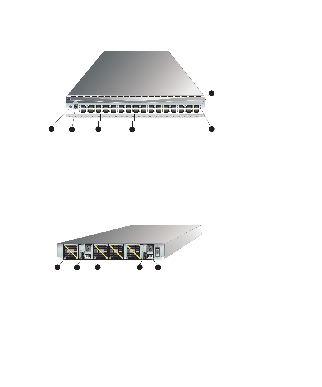
Front view
Figure 1 shows the front of the Edge Switch 2/32 and identifies the front panel components.
1
1
1 Initial machine load (IML) button
2 Ethernet LAN connector
3 SFP fiber-optic connectors
Figure 1 Edge Switch 2/32 (front view)
Rear view
Figure 2 shows the rear of the Edge Switch 2/32. The FRUs on the rear panel include two power
supplies and four individual cooling fan FRUs. Also shown on the rear panel is an RS-232
maintenance port (not labeled).
StorageWorks edge switch 2/32
10/100
IML
2
6
1
35791113151719212325272931
PWR
24
262830
3
4
ERR
0246810121416182022
5
4 Por t LEDs
5 Error LED (amber)
6 Power LED (g reen)
1
2
1 Cooling fan (4)
3 2
3 Power switches on power supplies (2)
2 Power supply (2)
Figure 2 Edge Switch 2/32 (rear view)
3
Edge Switch 2/32 installation guide 17
Page 18

SFP transceivers (fiber optic connectors)
A single-mode or multimode fiber-optic cable attaches to a port through a small form pluggable
(SFP) transceiver. The SFP provides a duplex LC interface, and can be detached from the switch port
for easy replacement. Two fiber-optic transceiver types are available:
• Shortwave laser—Shortwave laser SFPs provide short-distance connections (2 to 500 meters)
through 50-micron or 62.5-micron multimode fiber.
• Longwave laser—Longwave laser SFPs provide long-distance connections (up to 10 kilometers)
through 9-micron single-mode fiber.
• Extended longwave laser—Extended longwave laser SFPs provide long-distance connections (up
to 35 kilometers) through 9-micron single-mode fiber.
Cooling fans
Four fans (each a separate FRU) provide cooling for the switch power supplies and the control
processor (CTP) card, as well as redundancy for continued operation if a single fan fails.
Each fan FRU can be replaced while the switch is operating.
Power supplies
Redundant, load-sharing power supplies step down and rectify facility input power to provide 3.3
volts direct current (VDC), 5 VDC, and 12 VDC to the CTP. The power supplies also provide input
filtering, overvoltage protection, and overcurrent protection. Either power supply can be replaced
while the switch is operational.
Each power supply has a separate CTP connection to allow for independent AC power sources. The
power supplies are input-rated at 100 to 230 volts alternating current (VAC).
Power supply requirements are listed in.
Connectors and indicators
Connectors and indicators include the:
• Initial machine load (IML) button.
• Ethernet LAN connector.
• Power and System Error LEDs (green power (PWR) and amber system error (ERR) LEDs).
• FRU status LEDs (green and amber status LEDs associated with FRUs).
• Maintenance port (RS-232).
Initial machine load button
When the IML button (Figure 1 on page 17) is pressed and held for three seconds, the switch
performs an IML that takes approximately 30 seconds and resets the following:
• Microprocessor and functional logic for the CTP and loads firmware from FLASH memory.
• Ethernet LAN interface, causing the connection to the HAFM appliance to drop momentarily
until the connection automatically recovers.
Introduction18
Page 19

• Ports, causing all Fibre Channel connections to drop momentarily until the connections
automatically recover.
An IML should only be performed if a CTP failure is indicated. Do not IML the switch unless directed
to do so by a procedural step in this manual or by the next level of support. As a precaution, the IML
button is flush mounted to protect against accidental activation.
Ethernet LAN connector
The front panel provides a 10/100 megabit per second (Mbps) RJ-45 twisted-pair connector
(Figure 1 on page 17) that attaches to an Ethernet LAN to provide communication with the on
page 17 or an SNMP management workstation. Two green LEDs are associated with the LAN
connector. When illuminated, the left LED indicates LAN operation at 10 Mbps, and the right LED
indicates LAN operation at 100 Mbps.
Power and system error LEDs
The PWR LED (Figure 1on page 17) illuminates when the switch is connected to facility AC power
and powered on. If the LED extinguishes, a facility power source, power cord, or power distribution
failure is indicated.
The ERR LED (Figure 1 on page 17) illuminates when the switch detects an event requiring
immediate operator attention, such as a FRU failure. The LED remains illuminated as long as an
event is active. The LED extinguishes when the Clear System Error Light function is selected from the
Element Manager. The LED blinks if unit beaconing is enabled. An illuminated ERR LED (indicating
a failure) takes precedence over unit beaconing.
FRU status LEDs
Amber and green LEDs associated with switch FRUs provide status information as follows:
• Port SFP—Amber and green LEDs to the left of the port (Figure 1 on page 17) illuminate,
extinguish, or blink to indicate various port states (operational with active Fibre Channel traffic,
operational but not communicating, beaconing, blocked, failed, inactive, or running
diagnostics).
• Fan—An amber LED at the lower left corner of each fan (Figure 1 on page 17) illuminates if the
fan fails or rotates too slowly.
• Power Supply—A green LED at the upper left corner of each power supply (Figure 2 on
page 17) illuminates if the power supply is operational and receiving AC power.
Maintenance port
The rear panel provides a 9-pin RS-232 maintenance port (Figure 2 on page 17) that provides a
connection for a local terminal or dial-in connection for a remote terminal. Although the port is
typically used by authorized maintenance personnel, operations personnel can use the port to
configure switch network addresses.
Edge Switch 2/32 installation guide 19
Page 20
Tools and test equipment
This section describes tools and test equipment that may be required to install, test, service, and
verify operation of the switch and attached on the HAFM appliance.
Tools supplied with the switch
The following tools are supplied with the switch. Use of the tools may be required to perform one or
more installation, test, service, or verification tasks. These tools are supplied with the switch or must
be supplied by service personnel.
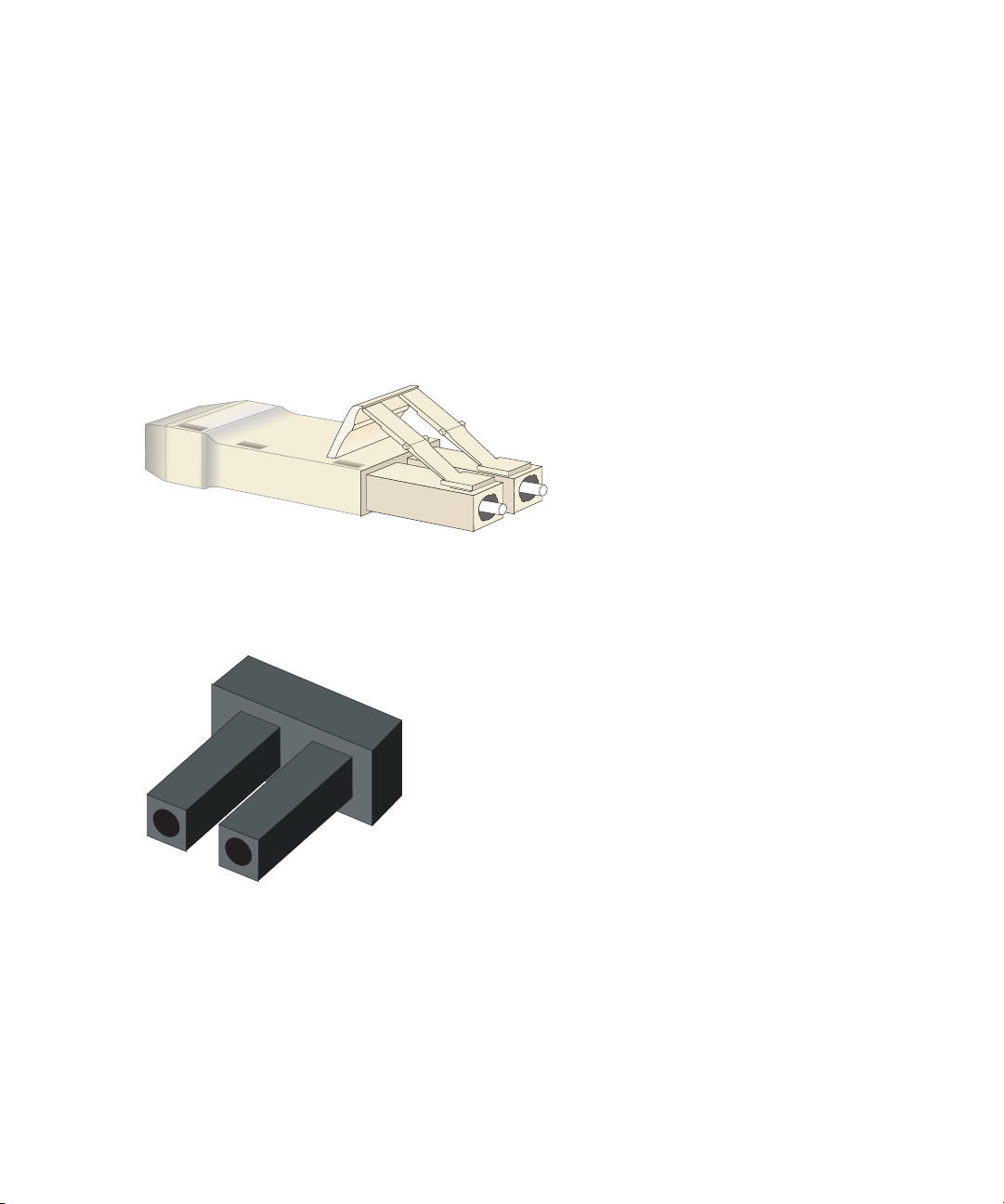
• Loopback plug—An SFP multi-mode (shortwave laser) or single-mode (longwave laser) loopback
plug as shown in Figure 3 is required to perform port loopback diagnostic tests. One loopback
plug is shipped with the switch, depending on the type of port transceivers installed. Both plugs
are shipped if shortwave laser and longwave laser transceivers are installed.
Figure 3 Loopback plug
• Fiber-optic protective plug—For safety and port transceiver protection, fiber-optic protective plugs
as shown in Figure 4 on page 20 must be inserted in all switch ports without fiber-optic cables
attached. The switch is shipped with protective plugs installed in all ports.
Figure 4 Fiber-Optic protective plug
Introduction20
Page 21
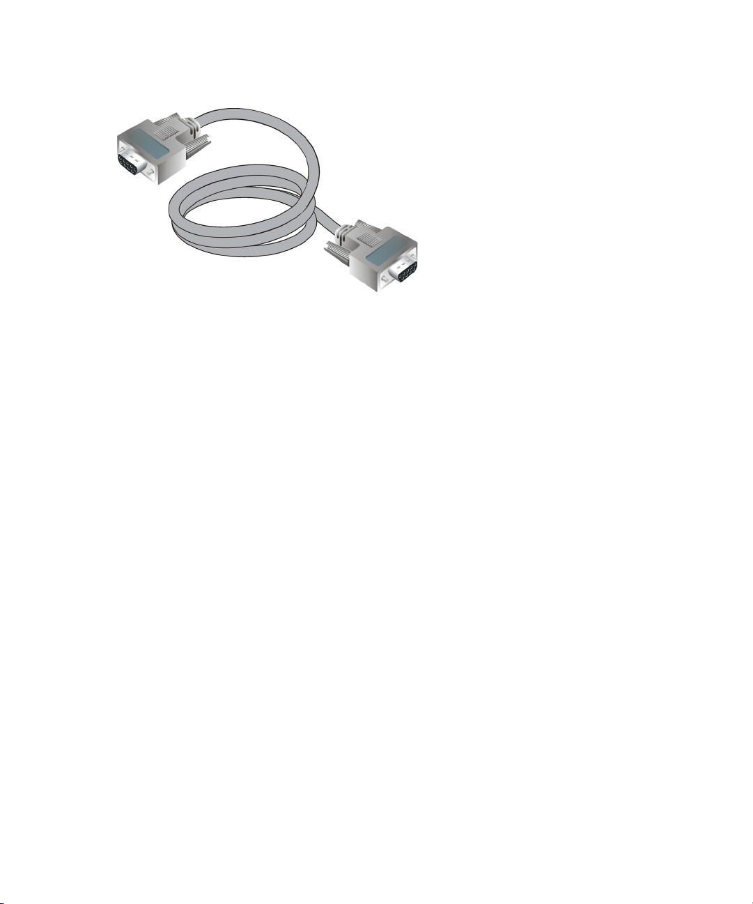
• Null modem cable—An asynchronous RS-232 null modem cable as shown in Figure 5 is
required to configure switch network addresses and acquire event log information through the
maintenance port. The cable has nine conductors and DB-9 male and female connectors.
Figure 5 Null modem cable
Tools supplied by service personnel
The following tools are expected to be supplied by service personnel performing switch installation
or maintenance actions. Use of the tools may be required to perform one or more test, service, or
verification tasks.
• Scissors or pocket knife—A sharp cutting edge (scissors or knife blade) may be required to cut
the protective strapping when unpacking replacement FRUs.
• Standard flat-tip and cross-tip (Phillips) screwdrivers—Screwdrivers are required to remove,
replace, adjust or tighten various FRUs, chassis, or cabinet components.
• Electrostatic discharge (ESD) grounding cable with attached wrist strap—Use of the ESD wrist
strap is required when working in and around the switch card cage.
• Maintenance terminal (desktop or notebook PC)—The PC is required to configure switch network
addresses and acquire event log information through the maintenance port. The PC must have:
• The Microsoft
®
Windows
Millennium Edition operating system installed.
• RS-232 serial communication software (such as ProComm Plus or HyperTerminal) installed.
HyperTerminal is provided with Windows operating systems.
• Fiber-optic cleaning kit—The kit contains tools and instructions to clean fiber optic cable,
connectors, loopback plugs, and protective plugs.
®
98, Windows 2000, Windows Server 2003, Windows XP, or
Edge Switch 2/32 installation guide 21
Page 22

Optional kits
Contact your HP authorized service provider to purchase the following optional Edge Switch 2/32
kits. See Table 2.
Table 2 Edge Switch 2/32 optional kits
Supporting Kit Description
8-flexport upgrade for the
Edge Switch 2/32
Part Number: 302660-B21
Edge Switch 2/32 Element Manager license
Part Number: 300658-B21
HP Open Trunking License
Part Number: 336000-B21
HP SANtegrity Binding License
Part Number: 317071-B21
300m Optical Transceiver Kit
Part Number: 300834-B21
10km Long Distance Optical Transceiver Kit.
Part Number: 300835-B21
35 km Extended Reach Optical Transceiver
Kit
Part Number: 300836-B21
Used to upgrade from 16 to 24 and from 24
to 32 ports.
Used when switch is managed through
HAFM.
Provides a license to use the Open Trunking
feature.
Provides a license to use the SANtegrity
Binding feature.
Provides short-wave optical transceiver for
the Edge Switch 2/32.
Provides 10 km long-wave optical
transceiver for the Edge Switch 2/32.
Provides 35 km long-wave optical
transceiver for the Edge Switch 2/32.
Introduction22
Page 23

2 Installing and configuring the Edge Switch 2/32
This chapter describes tasks to install, configure, and verify operation of the Edge Switch 2/32.
Some of the topics it covers include:
• Review installation requirements, page 23
• Unpack and inspect the switch, page 24
• Install the Edge Switch on a desktop, page 25
• Install the Edge Switch in a Rack, page 26
• Configure switch network information, page 30
• LAN-connect the switch, page 34
• HAFM appliance, page 34
• Frequently used HAFM settings, page 39
• Connect the switch to a Fabric, page 65
• Unpack, inspect, and install the Ethernet hub (optional), page 67
• Using HAFM from a remote location, page 67
Installation options
The switch is installed in one of two configurations. The options are:
• Table or desktop—one or more switches, an optional HAFM appliance, and an optional
Ethernet hub are installed at the customer facility on a desk or table top. Ethernet cabling
distance, and local area network (LAN) addressing issues must be considered.
• Customer-supplied equipment rack—one or more switches, an optional HAFM appliance, and
an optional Ethernet hub are installed in a customer-supplied equipment rack. Rack-mount
hardware is provided in the shipping container. Ethernet cabling, distance, and LAN addressing
issues must be considered.
Review installation requirements
Verify that the following requirements are met prior to switch and HAFM appliance installation.
Ensure that:
• A site plan is prepared, configuration planning tasks are complete, planning considerations are
evaluated, and related planning checklists are complete. Fabric and device connectivity are
evaluated, and the related planning worksheet is complete. Refer to the HP StorageWorks
HA-Fabric Manager User Guide.
• Support equipment and personnel are available for the installation.
• The required number and type of fiber-optic jumper cables are delivered and available. Ensure
that the cables are the correct length with the required connectors.
• Remote workstations or simple network management protocol (SNMP) workstations are
available (optional). Workstations are customer-supplied and connected through a corporate or
dedicated LAN.
Edge Switch 2/32 installation guide 23
Page 24

Verify that the following items are present before beginning installation:
• (Optional). An HP 9000, HP 10000, HP 11000, HP M-Series, HP rack system/e, or an
industry-standard 19-in rack.
• Two power outlets or different branches (for redundancy)
• Torque driver with cross-tip bit (for setting 22 in/lb. of torque)
• Fiber-optic protective plug—For safety and port transceiver protection, fiber-optic protective plugs
must be inserted in all switch ports without fiber-optic cables attached.
• Null modem cable—An asynchronous RS-232 null modem cable is required to configure switch
network addresses and obtain event log information through the maintenance port. The cable
has nine conductors and two DB-9 female connectors. A null modem cable specially designed
for this application is supplied with the Edge Switch 2/32.
• Standard flat-tip and cross-tip Phillips screwdrivers—Required to remove, replace, adjust or
tighten various FRUs, chassis, or rack components.
• Electrostatic discharge (ESD) grounding cable with attached wrist strap—Required when
working in and around the switch card cage.
• Maintenance terminal (desktop or notebook computer)—Required to configure switch network
addresses and acquire event log information through the maintenance port. Computer
requirements include:
• Microsoft Windows 98, Windows Millennium Edition, Windows NT 4.0, Windows 2000,
Windows Server 2003, or Windows XP operating system installed
• RS-232 serial communication software (for example, ProComm Plus, or HyperTerminal).
NOTE: The HAFM appliance may be used for this function. The HyperTerminal application
is included with the Windows operating system provided with the
Unpack and inspect the switch
This section provides instructions for unpacking and inspecting the Edge Switch 2/32 and installing
it in a desktop or rack-mount configuration.
To unpack and inspect the switch:
CAUTION: When you remove the switch from the carton, do not rest it on its rear window while
examining it. To do so may break the FRU handles.
1. Inspect the shipping containers for damage caused during transit. If a container is damaged,
ensure a representative from the freight carrier is present when the container is opened.
2. Unpack the shipping containers and inspect each item for damage. Save all shipping and
packing materials. Ensure that all items on the enclosed shipping list are in each container.
3. If any items are damaged or missing, customers should contact an HP authorized service
provider or reseller.
Installing and configuring the Edge Switch 2/3224
HAFM appliance.
Page 25

Install the Edge Switch on a desktop
To install and configure the switch on a desktop:
1. Remove the backing from the four adhesive rubber pads and apply the pads to the underside of
the switch. Ensure that the pads are aligned with the scribed circles at each corner.
2. Position the switch on a table or desktop as directed by the customer. Ensure:
• Grounded AC electrical outlets are available.
• Adequate ventilation is present.
• Areas with excessive heat, dust, or moisture are avoided.
• All planning considerations are met. Refer to the HP StorageWorks HA-Fabric Manager user
guide.
3. Verify that all FRUs are installed as ordered.
4. Verify that the SFP optical transceivers are installed as required for your installation.
5. Connect the U.S. or country-specific (optional) AC power cords to the right (PS0) and left (PS1)
receptacles at the rear of the chassis.
WARNING! IAn HP-supplied power cord is provided for each switch power supply. To prevent
electric shock when connecting the switch to primary facility power, use only the supplied power
cords, and ensure that the facility power receptacle is the correct type, supplies the required
voltage, and is properly grounded.
6. Connect the remaining ends of the AC power cords to separate facility power sources that
provide single-phase, 120 to 240 volt alternating current (VAC). This provides power
redundancy.
7. Turn on the power. Two power switches are on the back of the unit. Turn on both switches. The
unit powers on and performs power-on self-tests (POSTs). During POSTs:
a. The green power (PWR) LED on the front panel turns on.
b. The amber system error (ERR) LED on the front panel flashes momentarily while the switch is
tested.
c. The green LEDs associated with the Ethernet port flash momentarily while the port is tested.
d. The green and amber LEDs associated with the ports flash momentarily while the ports are
tested.
8. After successful POST completion, the green power (PWR) LED remains on and all other front
panel LEDs turn off.
9. If a POST error or other malfunction occurs, refer to the HP StorageWorks Edge Switch 2/32
service manual to isolate the problem.
Edge Switch 2/32 installation guide 25
Page 26

Install the Edge Switch in a Rack
This section describes how to rack mount the HP StorageWorks Edge Switch 2/32 in the
appropriate HP, or comparable, 19-inch Electronic Industries Association (EIA) rack:
• HP 9000 series, 10000 series and 11000 series racks
• HP rack system/e or 19-inch EIA rack
Rack mount checklist
This section describes the contents of the rack mount kit as well as tools or equipment required to
complete the installation.
NOTE: The hardware kit includes parts not required for the configuration described in these
instructions.
Mounting hardware
• Two (2) two-hole bar nuts
• Six (6) three-hole bar nuts (only 4 used)
• Eight (8) square alignment washers (required only for HP 9000, 10000 and 11000 series
racks)
• Eight (8) Phillips panhead screws (10-32 x 1/2) with split lock and flat washers
• Four (4) Phillips flathead screws (8-32 x 7/16)
• Ten (10) Phillips panhead screws (10-32 x 5/8) with flat washer (only 2 used)
• Six (6) Phillips flathead screws (6-32 x 3/8) (not used)
• Twelve (12) Phillips panhead screws (10-32 x 3/8) (not used)
• Four (4) 8-32 Keps nuts (not used)
Brackets and rails
Brackets and rails included in the kit are shown in Figure 6.
1 Two (2) fixed-length slide rails (one left and one right)
2 Two (2) Front brackets
3 Two (2) Rear brackets (long)
4 Two (2) Rear spacing bracket
Installing and configuring the Edge Switch 2/3226
Page 27
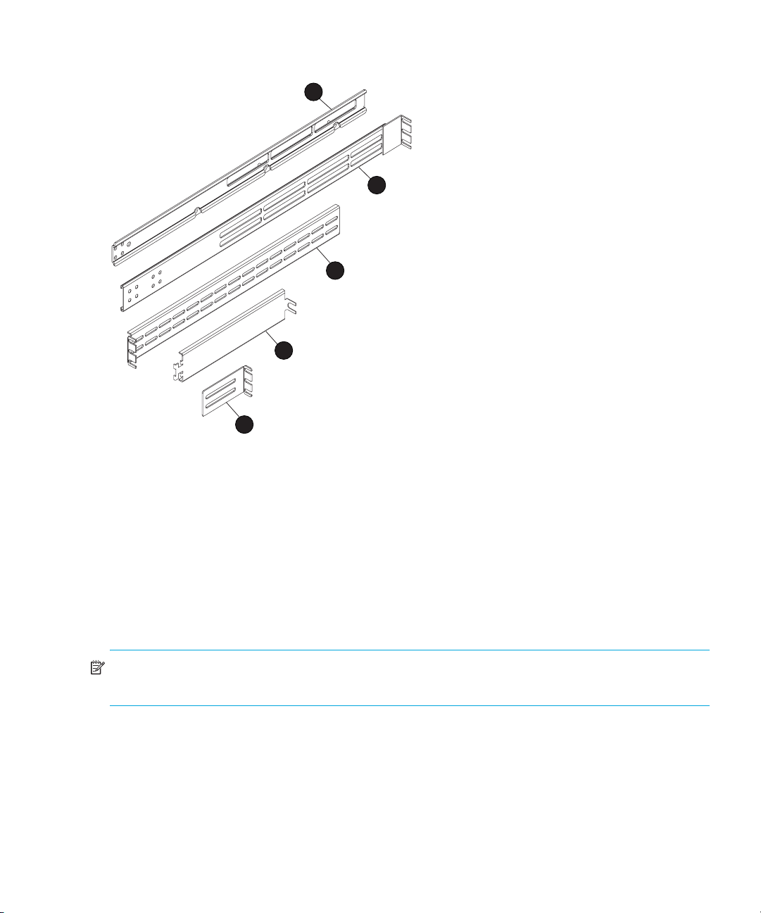
5 Rear bracket (short)–not used in this configuration
1
2
3
4
5
Figure 6 Brackets included in kit
Required tools
The following tools are required, but are not included in the kit:
• Torque driver with a T10 Torx bit
• #2 Phillips screwdriver
Mounting the adjustable brackets in the rack
Use these steps to install the adjustable brackets on the rack. You will need a #2 Phillips screwdriver
and eight 10x32 panhead screws to complete this procedure.
NOTE: If you are installing the Edge Switch 2/32 in an HP 9000, 10000 or 11000 series rack,
you will need eight square alignment washers to complete this procedure.
1. Determine the position of the switch in the rack. Each Edge Switch 2/32 is 1.75 inches or 1U
high.
Edge Switch 2/32 installation guide 27
Page 28

2. Attach four bar nuts (three-hole bar nuts) to the cabinet frame using eight (8) Phillips panhead
screws (10-32 x 1/2) with split lock and flat washers.
NOTE: Do not install a screw in the center hole of each bar nut.
a. If you are installing the Edge Switch 2/32 in an HP 9000, 10000 or 11000 series rack,
place a square alignment washer on each panhead screw before inserting in the square
cabinet frame holes.
b. Mount the bar nut on the inside of the cabinet frame. Orient the holes in the bar nut so that
they are aligned closest to the inside edge of the cabinet frame.
c. Secure, but do not completely tighten, all screws.
3. Measure cabinet depth from inside edge to inside edge of the cabinet frame.
4. Assemble two sets of front and rear brackets so that the combined brackets are equal to the
depth of the cabinet.
5. Attach a two-hole bar nut using four (4) Phillips flathead screws (8-32 x 7/16) to hold each
assembled bracket together. Do not completely tighten but tighten enough to hold the brackets
together.
6. Install the assembled brackets in the cabinet by sliding the mounting brackets between the bar
nut and cabinet frame.
7. Tighten the three-hole bar nut screws on the mounting brackets to where the rails are stable, but
can be easily adjusted.
8. Securely tighten the two-hole bar nut screws holding the front and rear brackets together.
Mounting the slide rails on the sides of the switch
Use these steps to install the slide rails on the sides of the switch as shown in Figure 7. You will need
a torque driver with a T10 Torx bit (not supplied in the kit) and left and right slide rails to complete
this procedure.
NOTE: You may want to remove the Edge Switch 2/32 power supplies, as this will make the
device lighter and easier to handle.
WARNING! Before removing the power supplies, review the HP StorageWorks Edge Switch 2/32
service manual for details on removing power supplies.
1. On the Edge Switch 2/32, remove the six screws (three screws per side) that help hold the switch
cover in place.
NOTE: Do not discard these screws, as you will use them to attach the slide rails.
Installing and configuring the Edge Switch 2/3228
Page 29
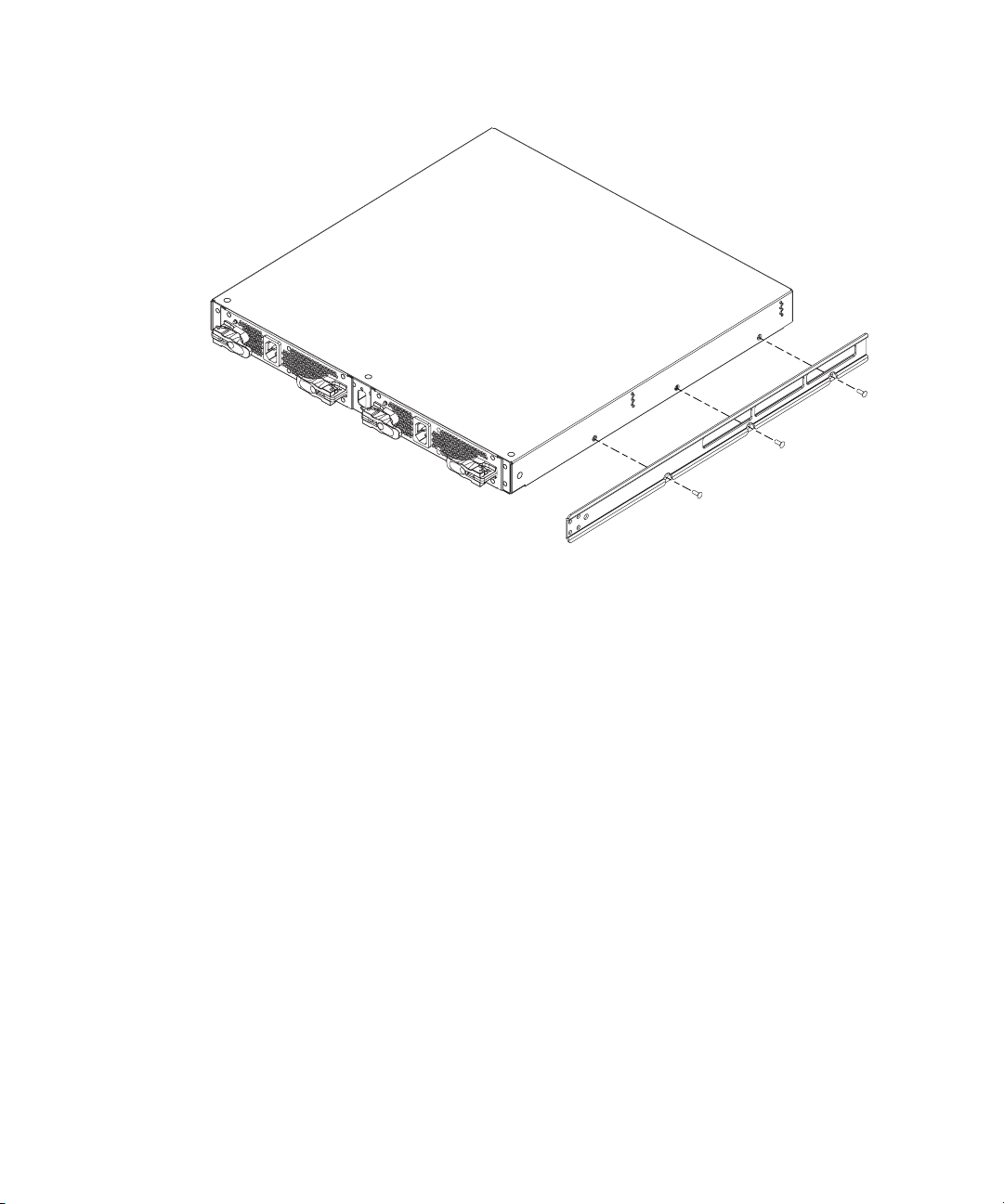
2. Using the torque driver and the screws you removed earlier, attach the left and right slide rails to
the Edge Switch 2/32.
Figure 7 Attaching the slide rail to the switch
Installing the switch in the cabinet
Use these steps to install the switch in the cabinet. You will need a #2 Phillips screwdriver and two
rear spacing brackets to complete this procedure.
1. From the front side of the cabinet, slide the switch into the mounting brackets and along the rails
until the rear of the switch is flush with the rear of the cabinet.
2. Bring the rear spacing brackets to the rear of the cabinet.
3. Pull the switch toward the rear of the cabinet until it protrudes approximately 3 inches.
4. Orient the rear spacing bracket mounts so that they are pointed outward. Insert the tabs on each
rear spacing bracket into the designated slots in each rail.
5. Push the switch forward using both rear spacing brackets until the rear spacing bracket mounts
contact the cabinet rail.
6. Attach the rear spacing brackets to the cabinet using two Phillips panhead screws (10-32 x 5/8)
with flat washer.
7. Ensuring that the square alignment washers are seated properly within the square cabinet frame
holes, use a Phillips head screwdriver to tighten the rear and front mounting screws.
Edge Switch 2/32 installation guide 29
Page 30

Configure switch network information
The Edge Switch 2/32 is delivered with the following default network addresses:
• MAC address—the media access control (MAC) address is programmed into FLASH memory on
the CTP card at the time of manufacture. The MAC address is unique for each switch, and should
not be changed. The address is in xx.xx.xx.xx.xx.xx format, where xx is a hexadecimal pair.
NOTE: References to the CTP in this manual are to the control processor logic contained on
the switch motherboard. If an event occurs that indicates the CTP as faulty, replacement of
the switch assembly is required.
• IP address—the factory preset default internet protocol (IP) address is 10.1.1.10. The default IP
address is also 10.1.1.10.
If Reset Configuration is selected from the Element Manager application, the switch resets to the
default address of 10.1.1.10.
If multiple switches are installed on the same LAN, each switch (and the HAFM appliance) must
have a unique IP address. One switch can use the factory-set address, but the addresses of the
remaining switches must be changed.
NOTE: If you have enabled additional port function with the HP Flexport feature since the
switch shipped from the factory, resetting the configuration will return this feature to the
factory default of only 16 ports enabled. You must re-enable the additional ports using the
Configure Feature Key dialog box (see ”Configure feature key” on page 64).
WARNING! This operation resets all configuration including any optional features that have
been installed. You will need to re-enter your feature key to enable all optional features after
resetting the configuration parameters.
• Subnet mask—the default subnet mask is 255.0.0.0. If the switch is installed on a complex
public LAN with one or more routers, the address may require change.
• Gateway address—the default gateway address is 0.0.0.0. If the switch is installed on a
dedicated LAN with no connection through a router, the address does not require change. If the
switch is installed on a public LAN (corporate intranet), the gateway address must be changed
to the address of the corporate intranet’s local router.
Verify that the type of LAN installation with the customer’s network administrator. If one switch is
installed on a dedicated LAN, network addresses do not require change.
Installing and configuring the Edge Switch 2/3230
Page 31

Changing the switch address
If multiple switches are installed or a public LAN segment is used, network addresses must be
changed to conform to the customer’s LAN addressing scheme. The following items are required to
perform this task:
• A local workstation (desktop or notebook computer) with:
• Microsoft Windows 98, Windows 2000, Windows Server 2003, Windows XP, or Windows
NT 4.0 operating system.
• RS-232 serial communication software (for example, ProComm Plus or HyperTerminal).
Note that the HAFM appliance may be used for this function and that HyperTerminal is included
with Windows 2000 or Windows Server 2003 provided in the HAFM appliance.
• An asynchronous RS-232 null modem cable (provided with the switch).
Perform the following steps to change a switch’s IP address, subnet mask, or gateway address:
1. Remove the protective metal plate from the 9-pin maintenance port at the rear of the switch (a
Phillips-tip screwdriver is required). Connect the 9-pin end of the RS-232 null modem cable to the
port.
2. Connect the other cable end to a 9-pin communication port (COM1 or COM2) at the rear of the
maintenance terminal PC.
3. Power on the maintenance terminal. After the PC powers on, the Windows desktop is displayed.
Refer to operating instructions shipped with the PC.
NOTE: Procedures for changing network addresses using the HyperTerminal serial
communication software are described in step 4 through step 13.
4. Select Start > Programs > Accessories > Communications > HyperTerminal. The Connection
Description dialog box is displayed, (Figure 8).
Figure 8 Connection Description dialog box
Edge Switch 2/32 installation guide 31
Page 32

5. Enter edge switch 2-32 in the Name field and click OK. The Connect To dialog box is displayed
(Figure 9).
Figure 9 Connect To dialog box
6. Ensure that the Connect using field displays COM1 or COM2 (depending on the serial
communication port connection to the switch), and click OK. The Port Settings dialog box is
displayed (Figure 10).
Figure 10 Port Settings dialog box
7. Enter the Port Settings parameters as follows:
•Bits per second—115200
• Data bits—8
•Parity—None
• Stop bits—1
• Flow control—Hardware
When the parameters are set, click OK. The HyperTerminal window is displayed.
Installing and configuring the Edge Switch 2/3232
Page 33

8. At the > prompt, enter the user-level password (the default is password) and press Enter. The
password is case sensitive. The HyperTerminal window is displayed with a C> prompt at the top
of the window (Figure 11).
Figure 11 HyperTerminal window
9. At the C> prompt, enter ipconfig and press Enter. The HyperTerminal window is displayed with
configuration information listed as follows:
•MAC Address
• IP Address (default is 10.1.1.10, factory preset is 10.1.1.10)
•Subnet Mask (default is 255.0.0.0).
• Gateway Address (default is 0.0.0.0)
Only the IP Address, Subnet Mask, and Gateway Address fields are configurable.
10.Change the IP address, subnet mask, and gateway address as directed by the customer’s
network administrator. To change switch network addresses, enter the following at the C>
prompt:
ipconfig xxx.xxx.xxx.xxx yyy.yyy.yyy.yyy zzz.zzz.zzz.zzz
The IP address is always xxx.xxx.xxx.xxx, the subnet mask is always yyy.yyy.yyy.yyy,
and the gateway address is always zzz.zzz.zzz.zzz. The octets xxx, yyy, and zzz are
decimals from zero through 255. If a network address is to remain unchanged, type the current
address in the respective field.
When the new network addresses are configured at the switch, the message Request
completed OK is displayed at the bottom of the Edge Switch 2/32—HyperTerminal window.
11.Select File > Exit close the HyperTerminal application. A message box is displayed (Figure 12).
Figure 12 Disconnect Now dialog box
Edge Switch 2/32 installation guide 33
Page 34

12.Click Yes. A message box is displayed (Figure 13).
Figure 13 Save Session dialog box
13.Click No to exit and close the HyperTerminal application.
14.Power off the maintenance terminal:
a. Select Start > Shut Down. The Shut Down Windows dialog box is displayed.
b. Select Shut Down Windows > Shut down the Computer and click Yes to power off the PC.
15.Disconnect the RS-232 null modem cable from the switch and the maintenance terminal. Replace
the plastic cover over the maintenance port.
LAN-connect the switch
Connect the switch to the Ethernet LAN segment or the HP-supplied Ethernet hub.
To connect the desktop or rack-mounted switch to the Ethernet LAN segment:
1. Connect one end of the Ethernet patch cable (supplied with the switch) to the RJ-45 connector
(labeled 10/100) on the left front of the chassis.
2. Connect the remaining end of the Ethernet cable to the LAN as follows:
a. If the switch is installed on a customer-supplied LAN segment, connect the cable to the LAN
as directed by the customer’s network administrator.
b. If the switch is installed on the HP-supplied Ethernet hub, connect the cable to any available
port on the hub.
3. Perform one of the following steps:
• If an HAFM appliance is delivered and available, go to ”HAFM appliance” on page 34.
• If an HAFM appliance is not available and the switch is managed through the Embedded
Web Server interface, attach the Ethernet LAN segment to an internet connection and go to
”Using the Embedded Web Server” on page 71.
HAFM appliance
To run HAFM software, you must set up and configure the HAFM appliance. Refer to the
HP StorageWorks HA-Fabric Manager appliance installation guide for instructions on:
• Setting up the HAFM appliance.
• Connecting the HAFM appliance to the LAN.
• Configuring the network addressing for the HAFM appliance.
• Setting the HAFM appliance date and time.
• Creating HAFM user names and passwords.
Installing and configuring the Edge Switch 2/3234
Page 35

Record or verify HAFM appliance restore information
Configuration information must be recorded to restore the HAFM appliance in case of hard drive
failure. The Windows operating system and the HAFM and Element Manager application must also
be restored. Refer to the HP StorageWorks HA-Fabric Manager appliance installation guide for
instructions.
To record or verify HAFM appliance configuration information, refer to the appropriate HAFM
appliance installation for instructions.
Enabling HAFM to manage the switch
To manage a new switch, it must be identified to the HAFM appliance. To identify the new switch:
1. At the HAFM application (Element manager or EWS main window), select Setup from the
Discover menu. The Discover Setup dialog box is displayed (Figure 14).
Figure 14 Discover Setup dialog box
2. Click Add. The Domain Information dialog box is displayed with the IP Address page open by
default (Figure 15).
Figure 15 Domain Information dialog box (IP Address page)
3. Enter a switch description (for example, edge-32) the Description field.
Edge Switch 2/32 installation guide 35
Page 36

4. Enter the switch IP address (determined by the customer’s network administrator) in the IP
Address field.
5. Enter the switch subnet mask (determined by the customer’s network administrator) in the Subnet
Mask field.
6. At the Data Source for Domain area of the dialog box, select the Use auto detection, Use the
server, or Use a specific RDC radio button (determined by the customer’s network administrator).
7. Click OK to save the entered information, close the dialog box, and define the switch to the
HAFM application.
8. Repeat step 2 through step 7 for each new switch.
9. Click OK to close the Discover Setup dialog box and return to the HAFM application.
Verify Communication between the switch and the HAFM appliance
Communication must be verified between the switch and the HAFM appliance Element Manager
and EWS applications. To verify switch-to-appliance communication:
1. At the management application’s main window (physical map or product list), inspect the shape
and color of the status symbol associated with the Edge Switch product icon. Table 3 explains
the symbols and associated operational states.
Table 3 Switch operational states and symbols
Operational state Symbol
Operational—switch-to appliance communication is established, the
switch is operational, and no failures are indicated. Go to ”Set Switch
date and time” on page 38. (
Degraded—switch-to-appliance communication is established, but the
switch is operating in degraded mode and requires service. This
condition is typical if a port or redundant FRU fails. Go to step 2.
Failed—switch-to appliance communication is established, but the switch
failed and requires immediate service. Go to step 2.
Status Unknown—the switch status is unknown because of a network
communication failure between the switch and HAFM appliance.
Go to step 2.
2. Right-click the switch icon at the HAFM application’s physical map. A pop-up menu appears.
Installing and configuring the Edge Switch 2/3236
Page 37

3. Select Element Manager from the pop-up menu. When the Element Manager application opens,
the last view (tab) accessed by a user opens by default. The example in Figure 16 shows the
Hardware View.
Figure 16 Switch Hardware View page
4. Inspect switch status at the Hardware View page and perform one of the following steps:
a. If the switch displays the Operational state (no FRU alert symbols and a green circle at the
alert panel), go to ”Set Switch date and time” on page 38.
b. If the switch displays the Degraded state or a switch failure is indicated (FRU alert symbols
and a yellow triangle or red diamond at the alert panel), refer to the HP StorageWorks Edge
Switch 2/32 service manual to isolate the problem.
Edge Switch 2/32 installation guide 37
Page 38

Set Switch date and time
The Edge Switch 2/32 Element Manager log entries are stamped with the date and time received
from the switch. To set the effective date and time for the switch:
1. At the Hardware View page for the selected switch, select Configure > Date/Time. The
Configure Date and Time dialog box is displayed (Figure 17).
Figure 17 Configure Date and Time dialog box
The switch date and time can be set manually, or set to be periodically updated by the HAFM
appliance (the switch and HAFM appliance synchronize at least once daily).
Set date and time manually
To set the switch date and time manually:
1. At the Configure Date and Time dialog box, click Periodic Date/Time Synchronization to
deselect the option (no check mark in the box). The greyed out Date and Time fields activate.
2. Click the Date fields that require change, and enter numbers in the following ranges:
Month (MM): 1 through 12
Day (DD): 1 through 31
Year (YY): greater than 1980
3. Click the Time fields that require change, and enter numbers in the following ranges:
Hour (HH): 0 through 23
Minute (MM): 0 through 59
Second (SS): 0 through 59
4. Click Activate to set the switch date and time and close the Configure Date and Time dialog
box.
Periodically synchronize date and time
To set the switch to periodically synchronize date and time:
1. Click Periodic Date/Time Synchronization to select the option (check mark in the box). The Date
and Time fields are greyed out and not selectable. Perform one of the following options:
•Click Activate to enable synchronization and close the Configure Date and Time dialog box.
The switch date and time synchronize with the HAFM appliance date and time at the next
update period (at least once daily).
•Click Sync Now to synchronize the switch and HAFM appliance immediately. The Date and
Time Synced dialog box is displayed.
Installing and configuring the Edge Switch 2/3238
Page 39

2. Click OK to synchronize the date and time and close the Date and Time Synced dialog box, then
click Activate to enable synchronization and close the Configure Date and Time dialog box.
Frequently used HAFM settings
This section summarizes the most common HAFM tasks, including:
NOTE: For a complete reference on HAFM functionality, refer to the HP StorageWorks HA-Fabric
Manager user guide.
• Set the switch online, page 39
• Set the switch offline, page 40
• Configure switch identification, page 40
• Configure switch management style, page 41
• Configure Switch Operating Parameters, page 42
• Configure fabric operating parameters, page 44
• Configure switch binding, page 47
• Configure ports (Open Systems management style), page 47
• Configure ports (FICON management style), page 51
• Configure port addresses (FICON), page 52
• Configure SNMP trap message recipients, page 53
• Configure, enable, and test e-mail notification, page 54
• Configure and enable call-home features, page 56
• Configure and enable ethernet events, page 56
• Configure threshold alerts, page 57
• Configure Open Systems management appliance, page 64
• Configure FICON management appliance, page 64
• Configure feature key, page 64
• Configure Open Trunking, page 64
• Enable Embedded Web Server, page 64
• Enable Telnet, page 64
Set the switch online
When the switch is set online, an attached device can log into the switch if the port is not blocked.
Attached devices can communicate with each other if they are configured in the same zone. Use
these steps to set the switch online:
1. Open HAFM. The Products View page is displayed.
2. Double-click the appropriate switch icon. The Hardware View page for the selected switch is
displayed.
Edge Switch 2/32 installation guide 39
Page 40

3. Select Maintenance > Set Online State. If the switch is offline, the Set Online State dialog box is
displayed, indicating the status is offline.
4. Click Set Online. A Warning dialog box is displayed, indicating status is online.
5. Click OK. The Status table displays Online.
Set the switch offline
When the Edge Switch 2/32 is set offline, all ports are set offline. The switch transmits the offline
sequence (OLS) to attached devices, and the devices cannot log in to the switch. Use these steps to
set the switch offline:
1. Notify the customer that the switch is going offline.
2. Open HAFM. The Products View page is displayed.
3. Select the appropriate switch icon. The Hardware View page for the selected switch is
displayed.
4. Select Maintenance > Set Online State. If the switch is online, the Set Online State dialog box is
displayed, indicating the status is Online.
5. Click Set Offline. A Warning dialog box is displayed, indicating the switch will be set offline.
6. Click OK.
Configure switch identification
Perform this procedure to configure the switch name, description, location, and contact person for
the HAFM application. The information is displayed in multiple dialog boxes throughout the
application. In addition, the Name, Location, and Contact variables configured at the
Configure Identification dialog box correspond respectively to the SNMP variables sysName,
sysLocation, and sysContact. These variables are used by SNMP management workstations
when obtaining data from managed switches.
To configure the switch identification:
1. At the Hardware View page for the selected switch, select Configure > Identification. The
Configure Identification dialog box is displayed (Figure 18).
Figure 18 Configure Identification dialog box
a. Type a switch name of 24 or fewer alphanumeric characters in the Name field. Each switch
should be configured with a unique name.
If the switch is installed on a public LAN, the name should reflect the switch’s Ethernet
network DNS host name. For example, if the DNS host name is hpes232.hp.com, enter
hpes232.
b. Click Set Name as Nickname and add a check mark if you want to use the name in the
name field as the nickname for the switch’s WWN. The nickname will display instead of the
WWN in Element Manager views.
Installing and configuring the Edge Switch 2/3240
Page 41

c. Type a switch description of 255 or fewer alphanumeric characters in the Description field.
d. Type the switch’s physical location (255 or fewer alphanumeric characters) in the
Location field.
e. Type the name of a contact person (255 or fewer alphanumeric characters) in the
Contact field.
2. Click Activate to configure the switch identification and close the dialog box.
Configure switch management style
NOTE: To change this value, you must first set the switch offline (see ”Set the switch offline” on
page 40). After you change the value, be sure to set the switch online again (see ”Set the switch
online” on page 39.)
Perform this procedure to set the switch to Open Systems or FICON management style. This setting
only affects the management style used to manage the switch; it does not affect port operation.
That is, OSI devices can communicate with each other if the switch is set to FICON management
style; FICON devices can communicate with each other if the switch is set to Open Systems
management style.
NOTE: If the FICON management appliance feature is enabled, the default management style is
FICON and the Open Systems management style cannot be enabled.
Typically, FICON management style is used when attaching an IBM S/390 Parallel Enterprise or
IBM zSeries server to the switch and implementing inband switch management through a Fibre
Connection (FICON) channel.
To configure the switch management style:
1. Ensure that the switch is set offline. For instructions, see ”Set the switch offline” on page 40.
2. Select Product > Management Style. The Configure Management menu is displayed.
3. Select the management style as follows:
• Open Systems— Use for all non-FICON Fibre Channel environments.
• FICON—If the FICON management appliance feature is enabled, the default style will be
FICON. You will not be able to change to Open Systems with the FICON management
appliance feature enabled.
4. Click Activate.
5. Set the switch online. For instructions, see ”Set the switch online” on page 39.
Edge Switch 2/32 installation guide 41
Page 42

Configure Switch Operating Parameters
Use the procedures in this section to set parameters on the switch for fabric operation through the
Configure Switch Parameters dialog box. These operating parameters are stored in NVRAM on the
switch.
1. The switch must be offline to change the Preferred Domain ID and other operating parameters.
Ensure that the switch is set offline. For instructions, see ”Set the switch offline” on page 40.
CAUTION: Setting the switch offline terminates all Fibre Channel connections.
2. Select Configure > Operating Parameters > Switch Parameters. The Configure Switch
Parameters dialog box is displayed (Figure 19).
Figure 19 Configure Switch Parameters dialog box
NOTE: Ordinarily, you do not need to change values in this dialog box from their defaults.
The only exception is the Preferred Domain ID. Change this value if the switch will participate
in a multiswitch fabric.
3. Use information in the ”Switch parameters” section, which follows, to change settings as
required for parameters in this dialog box.
4. After you change settings, click the Activate button.
5. Set the switch online. For instructions, see ”Set the switch online” on page 39.
Switch parameters
Configure the following parameters as required by your fabric.
Domain ID
The domain identification is a value from 1 through 31 that provides a unique identification for the
switch in a fabric. An Edge Switch cannot contain the same domain ID as another switch or their
E_Ports will segment when they try to join.
In the Configure Switch Parameters dialog box, a field is provided to enter a preferred domain ID
and a check box is provided to enable this ID as an insistent domain ID.
Installing and configuring the Edge Switch 2/3242
Page 43

Preferred
NOTE: To change this value, you must first set the switch offline. Select Set Online State from the
Maintenance menu to display the Set Online State dialog box, then click the button. Be sure to set
the switch back online after you change this value.
Use this field to set a unique domain ID for the switch. The default value is 1. Set a value from 1
through 31. When a switch comes online with a preferred ID, it requests an ID from the fabric’s
principal switch (indicating its preferred value as part of the request). If the requested domain ID is
not allocated to the fabric, the domain ID is assigned to the requesting switch. If the requested
domain ID is already allocated, an unused domain ID is assigned. Note that you must set the switch
offline before you can change to the preferred domain ID.
The preferred domain ID must be unique for each director and switch in a fabric. If two switches or
directors have the same preferred domain ID, the E_Ports segment, causing the fabric to segment.
For more information on domain ID, refer to the section on domain ID assignment for multiswitch
fabrics in the HP StorageWorks HA-Fabric Manager User Guide for details.
Insistent
This option is not supported unless the SANtegrity feature is installed. Click the check box to remove
or add a check mark. The default state is disabled (no check mark).
When a check mark is displayed, the domain ID configured in the Preferred Domain ID field will
become the active domain identification when the fabric initializes. See the following notes:
• This option is required if the HAFM is enabled.
• If you enable Insistent Domain while the switch or director is online, the Preferred Domain ID will
change to the current active domain ID if the IDs are different.
CAUTION: If a switch with a duplicate domain ID exists in the fabric, both switches' E_Ports will
segment when they try to join.
Rerouting Delay
Placing a check mark in the check box to the left of the Rerouting Delay option enables rerouting
delay. This option is only applicable if the configured switch is in a multiswitch fabric. The default
state is enabled.
Enabling the rerouting delay ensures that frames are delivered in order through the fabric to their
destination. If there is a change to the fabric topology that creates a new path (for example, a new
switch is added to the fabric), frames may be routed over this new path if its hop count is less than
a previous path with a minimum hop count. This may result in frames being delivered to a
destination out of order since frames sent over the new, shorter path may arrive ahead of older
frames still in route over the older path.
Edge Switch 2/32 installation guide 43
Page 44

If rerouting delay is enabled, traffic ceases in the fabric for the time specified in the E_D_TOV field
of the Configure Fabric Parameters dialog box. This delay allows frames sent on the old path to exit
to their destination before new frames begin traversing the new path.
NOTE: This option is required if High Availability Fabric Manager (HAFM) is enabled.
Domain RSCNs
Domain register for state change notifications (domain RSCNs) are sent between end devices in a
fabric to provide additional connection information to host bus adapters (HBA) and storage devices.
As an example, this information might be that a logical path has been broken because of a physical
event, such as a fiber-optic cable being disconnected from a port. Consult with your HBA and
storage device vendor to determine if enabling Domain RSCNs will cause problems with your HBA
or storage products. Note that this option is required if Enterprise Fabric Mode (optional SANtegrity
binding feature) is enabled.
Suppress RSCNs on zone set activations
Fabric format domain register for state change notifications (RSCNs) are sent to ports on the switch
following any change to the fabric's active zone set. These changes include activating and
deactivating the zone set, or enabling and disabling the default zone. When the Suppress RSCNs
on zone set activations check box is selected, fabric format RSCNs are not sent for zone changes to
the attached devices on the switch. Click the check box to remove or add a check mark.
This option is enabled (check box not selected) by default. In most cases this option should be
enabled so that attached devices can receive notification of zoning changes in the fabric. However,
some HBAs may log out, then log back into the fabric when they receive an RSCN, thereby
disrupting Fibre Channel traffic. Consult with your HBA and storage device vendor to determine if
disabling this option (and thereby enabling RSCN transmission) will cause problems with your HBA
or storage products.
Configure fabric operating parameters
Use procedures in this section to set parameters on the switch for fabric operation through the
Configure Fabric Parameters dialog box. These operating parameters are stored in NV-RAM on the
switch.
1. The switch must be offline to change parameters in this dialog box. Ensure that the switch is set
offline. For instructions, see ”Set the switch offline” on page 40.
CAUTION: Setting the switch offline terminates all Fibre Channel connections.
Installing and configuring the Edge Switch 2/3244
Page 45

2. At the Hardware View, select Operating Parameters > Fabric Parameters from the Element
Manager window. The Configure Fabric Parameters dialog box is displayed (Figure 20).
Figure 20 Configure Fabric Parameters dialog box
NOTE: Ordinarily, you do not need to change values in this dialog box from their defaults.
The only exception is the Preferred Domain ID. Change this value if the switch will participate
in a multiswitch fabric.
3. Use information under ”Fabric parameters” on page 45 to change settings as required for
parameters in this dialog box.
4. After you change settings, click Activate.
5. Back up the configuration data when you are finished configuring the switch.
6. Set the switch online. For instructions, see ”Set the switch online” on page 39.
Fabric parameters
Configure the following parameters as required by your fabric.
BB_Credit
Configure the switch to support buffer to buffer credit (BB_Credit) from 1 through 60. This is the
value used for all ports, except those configured for extended distance buffering (10-100 km). The
default value is 16. For a description of the buffer-to-buffer credit, refer to the industry specification,
Fibre Channel Physical and Signaling Interface.
R_A_TOV
Configure resource allocation time-out value (R_A_TOV) in tenth-of-a-second increments. This
variable works with the error detect time-out value (E_D_TOV) variable to control the switch’s
behavior when an error condition occurs. Resources are allocated to a circuit when errors are
detected and are not released for reuse until the time set by the R_A_TOV value expires. The default
value is 100 tenths (10 seconds). Set a value from 10 tenths through 1200 tenths (1 through 120
seconds).
Edge Switch 2/32 installation guide 45
Page 46

NOTE: Set the same value for R_A_TOV on all directors and switches in a multiswitch fabric. If the
value is not the same on all units, the fabric segments. Also, the value for R_A_TOV must be greater
than the value configured for E_D_TOV.
E_D_TOV
Adjust the E_D_TOV in tenth-of-a-second increments. An error condition occurs when an expected
response is not received within the time limit set by this value. The default value is 20 tenths (2
seconds). Set a value from 2 tenths through 600 tenths (.2 through 60 seconds).
NOTE: Set the same value for E_D_TOV on all switches and directors in a multiswitch fabric. If the
value is not the same, the fabric segments.
Switch priority
Setting this value determines the principal switch for the multiswitch fabric. Select Principal (highest
priority), Default, or Never Principal (lowest priority) from the Switch Priority drop-down list.
Setting these priority values determines the principal switch selected for the multiswitch fabric. For
example, if you have three switches in the fabric and set one as Principal, one as Default, and one
as Never Principal, the unit set to Principal becomes the principal switch in the fabric.
If all switches are set to Principal or Default, the switch with the highest priority and the lowest
WWN becomes the principal switch. Following are some examples of principal switch selection
when switches have these settings:
• If you have three switches and set all to Default, the switch with the lowest WWN becomes the
principal switch.
• If you have three switches and set two to Principal and one to Default, the switch with the
Principal setting that has the lowest WWN becomes the principal switch.
• If you have three switches and set two to Default and one to Never Principal, the switch with the
Default setting and the lowest WWN becomes the principal switch.
At least one switch in a multiswitch fabric needs to be set as Principal or Default. If all of the switches
are set to Never Principal, all of the interswitch links (ISLs) will segment. If all but one switch is set to
Never Principal and the switch that was principal goes offline, then all of the other ISLs will segment.
NOTE: HP recommends that you leave the switch priority setting as Default. If you are considering
setting this value to something other than default, refer to the section on principal switch selection for
multiswitch fabrics in the HP StorageWorks HA-Fabric Manager user guide for details.
In, for example, the audit log, you may notice that the Principal setting maps to a number code of 1,
Default maps to a number code of 254, and Never Principal maps to a number code of 255. The
number codes of 2-253 are not currently in use.
Installing and configuring the Edge Switch 2/3246
Page 47

Interop Mode
Select one of the following options:
• Homogeneous Fabric—Select this mode if the fabric contains only HP directors and switches that
are operating in Homogeneous Fabric mode.
• Open Fabric 1.0—Default. Select this mode if the fabric contains HP directors and switches, as
well as other open-fabric compliant switches. Select this mode for managing heterogeneous
fabrics.
Configure switch binding
This feature is managed through the Switch Binding submenu options available on the Element
Manager Configure menu. Using Switch Binding, you can specify devices and switches that can
attach to director and switch ports. This provides security in environments that include a large
number of devices by ensuring that only the intended set of devices attach to a switch or director.
For complete procedures on configuring this optional feature, refer to the HP StorageWorks Edge
Switch Element Manager user guide.
Configure ports (Open Systems management style)
If the switch is set to Open Systems management style, perform this procedure to define Fibre
Channel port names, configure ports as blocked or unblocked, enable extended distance operation
and link incident (LIN) alerts, configure port binding, and define port types.
To configure switch ports (Open Systems management style only):
1. At the Hardware View page for the selected switch, select Configure > Ports. The Configure Ports
dialog box (Open Systems management style) is displayed.
a. Select a blank Name field and enter a descriptive port name of 24 or fewer alphanumeric
characters. Use a name that reflects the device connected to the port.
b. Click the Blocked check box to block or unblock a port. A check mark in the box indicates
the port is blocked. Blocking the port prevents the attached device from communicating with
the switch. A blocked port continuously transmits the offline sequence (OLS) (Figure 21).
Edge Switch 2/32 installation guide 47
Page 48

Figure 21 Configure Ports dialog box (Open Systems management style)
c. Click 10-100 km or RX BB Credit, depending on which column you have displayed in your
Configure Ports dialog box.
NOTE: If a Switch supports BB credits by port, the 10-100 Km column is replaced by an RX
BB Credit column.
•Click the 10-100 km to enable extended distance buffering for a port. A check mark in the
box indicates extended distance operation up to 100 kilometers (through repeaters) is
enabled.
•Click the RX BB Credit to set minimum and maximum allowable port BB credit values. These
values vary by Director. If an invalid value is entered, an Invalid RX BB Credit error message
displays. The BB Credit value is validated as entered.
Click Activate and a RX-BB Credit Confirmation box displays. In addition to the maximum
BB credit limit per port, the total BB credits allocated to all ports cannot exceed the buffer
pool size.
NOTE: Only 24-Port switches have a switch-wide buffer pool. The Configure Ports dialog
box displays the total and available buffers at the bottom of the dialog box. When
information is changed in the RX BB Credit column, this information also updates. If
information is entered that exceeds the buffer pool and Activate is clicked, an error message
displays. Also, ports for the 24-Port switches can be individually configured between 2–12,
with a total number of port credits of 150.
Installing and configuring the Edge Switch 2/3248
Page 49

Right-clicking in the RX-BB Credit column displays a RX BB Credits dialog box. For switches
without buffer pools, this dialog box allows you to select Set all, which sets all ports to a
single value or Set all to maximum, which set all ports to a maximum BB credit value. For
switches with buffer pools, this dialog box allows you to select Set all, which sets all ports to
a single value or to Distribute, which evenly distributes the pool buffers among all ports.
Clicking OK changes the values in the Configure Port dialog box. Clicking Activate changes
the values on the Switch.
d. Click LIN Alerts to enable or disable LIN alerts for a port. A check mark in the box indicates
alerts are enabled. When the feature is enabled and an incident occurs on the link, an alert
indicator (yellow triangle) is displayed at the Hardware View, Port List View, and Port Card
View pages, and a message is sent to configured e-mail recipients. LIN alerts are enabled by
default.
e. Click Type for a specified port and select generic port (G_Port), fabric port (F_Port), or
expansion port (E_Port) from the list box.
f. Click Speed for a specified port. A Speed drop-down list is displayed. Select 1Gb/s,
2Gb/s, or Negotiate as the desired setting, depending on the speed capability of the
device to be plugged into the port.
TIP: A right-click in the Speed column allows you to select from a menu to set all ports to
1Gb/s, 2Gb/s, or Negotiate.
g. Click a Port Binding check box to display a check mark and enable WWN binding for the
selected port. This allows only a specific device to attach to the port. This device is specified
by the WWN or nickname entered into the Bound WWN column. With the check box
cleared, any device can attach to the port even if a WWN or nickname is specified in the
Bound WWN column.
or
Enter a world wide name (WWN) in the Bound WWN field in the proper format
(xx.xx.xx.xx.xx.xx.xx.xx) or a nickname configured through the Element Manager
application. The device with this WWN or nickname will have exclusive attachment to the
port if Port Binding is enabled. If a valid WWN or nickname is not entered in this field, but
the Port Binding check box is checked (enabled), then no devices can connect to the port. If
you enter a WWN or nickname in this field and do not place a check in the Port Binding
check box, the WWN or nickname will be stored, and all devices can connect to the port.
2. Use the vertical scroll bar as necessary to display additional port information rows (up to 32
ports).
3. Click Activate to save the configuration information and close the dialog box.
Edge Switch 2/32 installation guide 49
Page 50

Configure preferred ports
The preferred path feature lets you specify and configure one or more ISL data paths between
multiple directors or switches in a fabric. Each participating director or switch must be configured as
part of a desired path. The following rules apply when configuring a preferred path:
• The switch domain ID must be set to Insistent. For instructions, refer to ”Configure Switch
Operating Parameters” on page 42.
• Domain IDs range between 1 through 31.
• Source and exit port numbers are limited to the range of ports available on the director or switch
(0 through 23).
• For each source port, only one path is defined to each destination domain ID.
NOTE: Activating a preferred path can result in receipt of out-of- order frames if the
preferred path differs from the current path, if input and output (I/O) is active from the source
port, and if congestions is present on the current path.
To configure one or more preferred paths for the switch:
1. At the Hardware View, select Configure > Preferred Path. The Configure Preferred Paths dialog
box is displayed (Figure 22).
Figure 22 Configure Preferred Paths dialog box
2. Click Add. The Add Preferred Path dialog box is displayed (Figure 23).
Figure 23 Add Preferred Path dialog box
Installing and configuring the Edge Switch 2/3250
Page 51

3. At the Source Port field, enter a value between 0 through 23. For this switch, the value uniquely
identifies the starting port for the preferred path.
4. At the Exit Port field, enter a value between 0 through 23. For this switch, the value uniquely
identifies the exit port for the preferred path.
5. At the Destination Domain ID field, enter a value between 1 through 31. This value uniquely
identifies the destination director or switch in the path.
6. Click OK to close the Add Preferred Path dialog box and add the path to the list at the Configure
Preferred Paths dialog box.
7. Repeat step 2 through step 6 to configure additional preferred paths.
8. At the Configure Preferred Paths dialog box, click the Enable Preferred Path check box.
9. Click Activate to enable all configured preferred paths and close the dialog box.
Configure ports (FICON management style)
If the switch is set to FICON management style, perform this procedure to enable extended distance
operation and LIN alerts for Fibre Channel ports. Then, continue to ”Configure port addresses
(FICON)” on page 52 to define port names, configure ports as blocked or unblocked, and define
the control unit port (CUP).
To configure switch ports:
1. At the Hardware View page for the selected switch, select Configure > Ports. The Configure Ports
dialog box (FICON management style) is displayed (Figure 24).
Figure 24 Configure Ports dialog box (FICON management style)
Edge Switch 2/32 installation guide 51
Page 52

a. Click 10-100 km to enable extended distance buffering for a port. A check mark in the box
indicates extended distance operation up to 100 kilometers (through repeaters) is enabled.
b. Click LIN Alerts to enable or disable LIN alerts for a port. A check mark in the box indicates
alerts are enabled. When the feature is enabled and an incident occurs on the link, an alert
indicator (yellow triangle) is displayed at the Hardware View, Port List View, and Port Card
View pages, and a message is sent to configured e-mail recipients. LIN alerts are enabled by
default.
c. Click the WWN Binding check box to display a check mark and enable WWN binding for
the port. This allows only a specific device to attach to the port. This device is specified by the
WWN or nickname entered into the Bound WWN column. With the check box cleared, any
device can attach to the port even if a WWN or nickname is specified in the Bound WWN
column.
d. Select a port speed in the Speed field.
e. Enter a World Wide Name (WWN) in the Bound WWN field in the proper format
(xx.xx.xx.xx.xx.xx.xx.xx) or a nickname configured through the Element Manager
application. The device with this WWN or nickname will have exclusive attachment to the
port if WWN Binding is enabled. If a valid WWN or nickname is not entered in this field,
but the WWN Binding check box is checked (enabled), then no devices can connect to the
port. If you enter a WWN or nickname in this field and do not place a check in the WWN
Binding check box, the WWN or nickname will be stored, and all devices can connect to
the port.
2. Use the vertical scroll bar as necessary to display additional port information rows (up to 64
ports).
3. Click Activate to save the configuration information and close the dialog box.
Configure port addresses (FICON)
If the switch is set to FICON management style, configure port addresses to access the switch matrix
and define Fibre Channel port names, configure ports as blocked or unblocked, and define the CUP
name. For instructions on configuring port addresses, refer to the HP StorageWorks Edge Switch
Element Manager user guide.
Installing and configuring the Edge Switch 2/3252
Page 53

Configure SNMP trap message recipients
Perform this procedure to configure community names, write authorizations, and network addresses
for up to 12 SNMP trap message recipients per HAFM appliance or up to 6 SNMP trap message
recipients per switch. A trap recipient is a management workstation that receives notification
(through SNMP) if a switch event occurs.
To configure SNMP trap recipients:
1. At the Hardware View page for the selected switch, select Configure > SNMP Agent. The
Configure SNMP Agent dialog box is displayed (Figure 25).
Figure 25 Configure SNMP Agent dialog box
a. For each trap recipient to be configured, enter a community name of 64 or fewer
alphanumeric characters in the associated Community Name field. The community name is
incorporated in SNMP trap messages to ensure against unauthorized viewing or use.
b. Click the check box in the Write Authorization column to enable or disable write
authorization for the trap recipient (default is disabled). A check mark in the box indicates
write authorization is enabled. When the feature is enabled, a management workstation user
can change the HAFM appliance’s sysContact, sysName, and sysLocation SNMP
variables.
c. Enter the IP address or DNS host name of the trap recipient (SNMP management
workstation) in the associated Trap Recipient field. Use 32 or fewer alphanumeric characters.
HP recommends using the IP address.
d. The default user datagram protocol (UDP) port number for trap recipients is 162. Enter a
decimal port number in the associated UDP Port Number field to override the default.
2. To enable transmission of trap messages to configured SNMP management workstations, click
Enable Authorization Traps. A check mark is displayed in the box when transmission is enabled.
3. Click Activate to save the information and close the dialog box.
Edge Switch 2/32 installation guide 53
Page 54

Configure, enable, and test e-mail notification
Perform this procedure to configure, enable, and test e-mail and simple mail transfer protocol
(SMTP) addresses to receive notification of switch (and other product) events. Configure and test
procedures are performed at the HAFM appliance. E-mail notification is enabled for each switch at
the HAFM application.
To configure, enable, and test e-mail server addresses:
1. Minimize the Hardware View and return to the HAFM application.
2. At the HAFM application or EWS main window, select Monitor > Event Notification > Email. The
Email Event Notification Setup dialog box is displayed (Figure 26).
Figure 26 Configure Email dialog box
3. Enter the IP address or DNS host name of the SMTP server in the E-mail Server field. Use 64 or
fewer alphanumeric characters. HP recommends using the IP address.
4. Enter the e-mail address to which e-mail replies should be sent in the Reply Address field.
5. At the Summary Interval field, enter the length of time the application should wait between
notifications. Select seconds, minutes, or hours from the associated drop-down list.
Installing and configuring the Edge Switch 2/3254
Page 55

6. To specify users that are to receive e-mail notification, click User List. The HAFM 8.6 Server
Users dialog box is displayed, as shown in Figure 27.
Figure 27 HAFM 8.6 Server Users dialog box
7. To enable e-mail notification for a user, select the check box in the Email column. An unchecked
box indicates e-mail notification is not enabled.
8. To configure event types for which e-mail notification is sent, select the Filter link adjacent to the
check box. The Define Filter dialog box is displayed.
Figure 28 Define Filter dialog box
9. Select the filters that you want for this user.
10.Click OK to close the Define Filter dialog box.
11.Click OK to close the HAFM 8 Server Users dialog box.
12.Click Test Email. A test message is sent to configured e-mail recipients.
13.Click OK to save the information and close the Email Event Notification Setup dialog box.
14.Maximize the Hardware View (Element Manager).
Edge Switch 2/32 installation guide 55
Page 56

15.At the Hardware View, select Maintenance > Enable E-Mail Notification. A check mark is
displayed in the check box to indicate e-mail notification for the switch is enabled, and the menu
closes.
NOTE: Using HAFM, enable or disable e-mail event notification for each switch
individually.
Configure and enable call-home features
There are two call-home features available, and only one is installed when the HAFM application is
installed on the HAFM appliance. To learn more about configuring call-home features, refer to the
HP StorageWorks HA-Fabric Manager Appliance installation guide.
Configure and enable ethernet events
Perform this procedure to configure and enable Ethernet events. An Ethernet event is recorded (after
a user-specified time interval) when the switch-to-HAFM appliance communication link drops. To
configure and enable Ethernet events:
1. Minimize the Hardware View and return to the HAFM application.
2. At the HAFM or EWS main window, select the Monitor > Ethernet Event. The Configure Ethernet
Events dialog box is displayed (Figure 29).
Figure 29 Configure Ethernet Events dialog box
3. Click the Enable Ethernet Events check box. A check mark is displayed in the check box to
indicate Ethernet events are enabled.
4. Enter a value from 10 through 120 minutes in the Ethernet Timeout field.
5. Click OK to close the dialog box.
Installing and configuring the Edge Switch 2/3256
Page 57

Configure, enable, and test call home event notification
Telephone numbers and other information for the call-home feature are configured through the
Windows 2000 dial-up networking application. Refer to ”Configure and enable call-home features”
on page 56 for configuration information. To configure, enable, and test call- home event
notification:
1. Minimize the Hardware View and return to the HAFM application.
2. At the HAFM or EWS main window, select the Event Notification and Call Home options from
the Monitor menu. The Call Home Event Notification Setup dialog box is displayed (Figure 30).
Figure 30 Call Home Event Notification Setup dialog box
3. Click the Enable Call Home Event Notification check box. A check mark is displayed in the check
box to indicate call-home event notification is enabled.
NOTE: The enable function must also be activated for each switch through the Element
Manager application. Call-home event notification can be active for some switches and
inactive for others.
4. Click Send Test. A call-home test message is sent.
5. Click OK to close the dialog box.
6. Maximize the Hardware View page.
7. At the Hardware View, select Enable Call Home Notification from the Maintenance menu. A
check mark appears in the check box to indicate call-home event notification for the switch is
enabled, and the menu closes.
Configure threshold alerts
A threshold alert notifies users when the transmit (Tx) or receive (Rx) throughput reaches specified
values for specific switch ports or port types, (E_Ports or F_Ports).
You are notified of a threshold alert in four ways:
• A yellow triangle that is displayed on the port in the Port Card View.
• A yellow triangle that is displayed on the port in the Hardware View.
• A yellow triangle that is displayed in the Alert column of the Port List View.
• A yellow triangle that is displayed by the Threshold Alerts field in the Port Properties dialog box.
• Detailed threshold alert data recorded in the Threshold Alert Log.
Edge Switch 2/32 installation guide 57
Page 58

Use the Threshold Alerts option on the Configure menu to configure the following:
• Name for the alert.
• Enter of threshold for the alert (Rx, Tx, or either).
• Active or inactive state of the alert.
• Threshold criteria:
• Percent traffic capacity utilized—The percent of the port’s throughput capacity achieved by
the measured throughput. This setting constitutes the threshold value. For example a value of
50 means that the port’s threshold is reached when throughput is 50% of capacity.
• Time interval during which throughput is measured and alert notification can occur.
• The maximum cumulative time that the throughput percentage threshold can be exceeded
during the set time interval before an alert is generated.
• Ports for which you are configuring threshold alerts.
You can configure up to 16 alerts, and any number of alerts can be active at one time. Use the
following procedures to create a new threshold alert, or to modify, activate, deactivate, or delete an
alert.
Create new alerts
1. At the Hardware View page, select Configure > Threshold Alerts. The Configure Threshold Alerts
dialog box is displayed, as shown in Figure 31.
NOTE: If alerts are configured, they will display in table format showing the name of the
alert, type of alert (Rx, Tx, or Rx or Tx), and alert state (inactive or active).
Figure 31 Configure Threshold Alerts dialog box
Installing and configuring the Edge Switch 2/3258
Page 59

2. Click New. The New Threshold Alert dialog box is displayed, as shown in Figure 32.
Figure 32 New Threshold Alerts dialog box
3. Enter a name from one to 64 characters in length in the Threshold Alert Name field. All
characters in the ISO Latin-1 character set, excluding control characters, are allowed.
4. Select one of the following from the Threshold Type drop-down list:
• Transmit—An alert will occur if the threshold set for transmit throughput is reached.
• Receive—An alert will occur if the threshold set for receive throughput is reached
• Receive and Transmit—An alert will occur if the threshold set for either receive or transmit
throughput is reached.
5. Click Next. A new screen is displayed with additional parameters, as shown in Figure 33. The
name configured for the alert appears at the top of the screen.
NOTE: Click Previous if you need to return to the previous screen.
—first screen
Figure 33 New Threshold Alerts dialog box—second screen
Edge Switch 2/32 installation guide 59
Page 60

6. Enter a percentage from 1 through 100 for % utilization. When throughput reaches this
percentage of port capacity, a threshold alert will occur.
7. Enter the amount of cumulative minutes in which the % utilization should exist during the
notification interval before an alert is generated. You can also select At any time if you want an
alert to occur whenever the set % utilization is reached. The valid range is from 1 to the interval
value set in step 8.
8. Enter the interval in minutes in which throughput is measured and threshold notifications can
occur. The valid range is 5 minutes to 70,560 minutes.
9. Click Next. A new screen is displayed for selecting ports for the alerts, as shown in Figure 34.
Figure 34 New Threshold Alerts dialog box
10.Select either Port Type or Port List.
• For Port Type, select either E_Ports or F_Ports to cause this alert to generate for all ports
configured as E_Ports or F_Ports respectively.
• For Port List, you can select individual ports by clicking the check box by each port number or
set all ports. Selecting Set All Ports places a check mark by each port number. Selecting
Clear All Ports clears the check marks by each port number.
Installing and configuring the Edge Switch 2/3260
—third screen
Page 61

11.Click Next. A final screen is displayed to provide a summary of your alert configuration, as
shown in Figure 35.
Figure 35 New Threshold Alerts dialog box
12.Click Finish. The Configure Threshold Alerts dialog box is displayed with a list of the name, type,
and state of the alert that you just configured.
13.At this point, the alert is not active. To activate the alert, select the alert information that appears
in the Configure Threshold Alerts table and click Activate as shown in Figure 36. The alert is
activated.
Figure 36 Configure Threshold Alerts dialog box
—summary screen
—alert activated
Edge Switch 2/32 installation guide 61
Page 62

Modify alerts
Use the following steps to modify an existing threshold alert configuration:
1. At the Hardware View page, select Configure > Threshold Alerts. The Configure Threshold Alerts
dialog box is displayed.
Select the alert that you want to modify by clicking the alert information in the table. If the alert
is active, an error message is displayed prompting you to deactivate the alert.
2. If the alert is active, click Deactivate, then select the alert information in the table again.
3. Click Modify. An initial Modify Threshold screen that allows the you to change the threshold type
is displayed.
4. Select a threshold type from the drop-down list.
5. Click Next when you are done. A Modify Threshold screen is displayed. This screen allows you
to change the % utilization, cumulative minutes for the threshold to occur before notification, and
the time interval for measuring throughput and for alert notification.
6. Make appropriate changes, then continue through the Modify Threshold screens, making
changes as necessary, until the summary screen is displayed in the alert configuration.
7. Perform either of the following steps:
• If you need to change any parameters, click Previous or Next to display the desired Modify
Threshold screen.
•Click Finish when you are done.
Activate or deactivate alerts
Use the following steps to activate or deactivate existing threshold alerts. In the active state,
notifications are generated for the alert. In the inactive state, notifications do not occur.
1. At the Hardware View page, select Configure > Threshold Alerts. The Configure Threshold Alerts
dialog box is displayed.
The port’s current state, inactive or active, is listed in the State column.
2. To change the state, select the alert by the alert information in the table.
3. If the alert is active, select Deactivate to change to the inactive state. If the alert is inactive, select
Activate to change to the active state.
Delete alerts
Use the following steps to delete existing threshold alerts:
1. At the Hardware View page, select Configure > Threshold Alerts. The Configure Threshold Alerts
dialog box is displayed.
2. Select the alert that you want to delete by selecting the alert information in the table and click
Delete. A message is displayed asking you to confirm the deletion.
3. Click Yes. The alert is removed from the dialog box.
Installing and configuring the Edge Switch 2/3262
Page 63

Configure SANtegrity authentication
Use this optional feature to configure authentication security settings. You configure these setting
using the SANtegrity Authentication dialog box.
NOTE: You must have Administrator privileges to access the SANtegrity Authentication dialog box.
To access the SANtegrity Authentication dialog box:
From the Element Manager window, select Configure > SAN
Authentication dialog box is displayed (Figure 37).
Figure 37 SANtegrity Authorization dialog box
This dialog box contains five tabs:
• Users—Allows you to setup users who access the switch from CLI and Web interfaces.
• Software—Allows you to setup software applications that communicate with the switch
through API, as well as OSMS authentication.
• Devices—Allows you to set device-to-device authentication parameters. The Devices tab is
preferred path PFE key enabled. If a proper PFE key is not provided, the Devices tab is not
accessible. See ”Configure feature key” on page 64 for more information.
• IP Access Control—Allows you to setup IP addresses that can manage the switch.
• Radius Servers—Allows you to set Radius server parameters that the switch uses to
communicate the authentication information to the designated Radius servers.
tegrity Authentication. The SANtegrity
For information about using each of these tabs, see the online Help.
Edge Switch 2/32 installation guide 63
Page 64

Back up HAFM configuration data
It is important to back up the HAFM configuration data. This data is used to restore the HAFM
appliance operating environment in case of hard drive failure. Refer to the HP StorageWorks
HA-Fabric Manager appliance installation guide for instructions on backing up the HAFM
configuration data.
Once the HAFM configuration data is backed up, go to ”Connect cables to Fibre Channel ports” on
page 65.
Configure Open Systems management appliance
For complete procedures on configuring this optional feature, refer to HP StorageWorks Edge Switch
Element Manager user guide.
Configure FICON management appliance
For complete procedures on configuring this optional feature, refer to HP StorageWorks Edge Switch
Element Manager user guide.
Configure feature key
For complete procedures on configuring this feature, refer to HP StorageWorks Edge Switch Element
Manager user guide.
Configure Open Trunking
This option is only available if the optional Open Trunking feature is installed. Selecting this option
opens the Configure Open Trunking dialog box. For details on enabling Open Trunking and
configuring such parameters as congestion thresholds for ports, event notification options, and low
BB credit threshold, refer to the HP StorageWorks Edge Switch Element Manager user guide.
Enable Embedded Web Server
Use the following steps to enable EWS:
1. At the Hardware View page, select Configure > Enable Web Server. Selecting Enable Web
Server automatically places a check mark in the check box.
2. Select Enable Web Server again to remove the check mark and disable the EWS interface.
When disabled, remote users cannot access the interface.
For complete information on using the EWS, see ”Using the Embedded Web Server” on page 71.
Enable Telnet
Use the following steps to enable Telnet:
1. At the Hardware View, select Configure > Enable Telnet. Selecting Enable Telnet automatically
places a check mark in the check box.
2. Select Enable Telnet again to remove the check mark and disable Telnet access. When disabled,
remote users cannot access the switch through Telnet.
Installing and configuring the Edge Switch 2/3264
Page 65

Connect cables to Fibre Channel ports
Perform this task to connect devices to the switch. To cable Fibre Channel ports:
1. Route single mode or multimode fiber-optic cables (depending on the type of SFP pluggable
optic transceivers installed) from the desired devices to ports at the front of the switch.
2. Connect device cables to small form factor pluggable (SFP) transceivers.
3. Perform one of the following:
a. If the switch is installed on a table or desk top, bundle and secure the Fibre Channel cables
as directed by the customer.
b. If the switch is installed in an HP-supplied equipment rack, bundle Fibre Channel cables from
the switch and other equipment (groups of 16 maximum), and secure them as directed by the
customer.
4. Set the switch online.
Connect the switch to a Fabric
To provide Fibre Channel connectivity between public devices and fabric-attached devices, connect
the switch to an expansion port (E_Port) of an HP director or switch. The switch port to switch port
connection is called an interswitch link (ISL). To fabric-attach the switch and create an ISL:
1. Ensure that the switch is defined to the HAFM application or defined to the HAFM appliance
(defined while performing ”Enabling HAFM to manage the switch” on page 35).
2. Ensure that the preferred domain ID for the switch is unique and does not conflict with the ID of
another switch or director participating in the fabric. To change the domain ID, see ”Configure
Switch Operating Parameters” on page 42.
• If the domain ID must be changed from the HAFM interface, see ”Configure Switch
Operating Parameters” on page 42.
• If the domain ID must be changed from the Element manager, see ”Configure switch and
fabric parameters” on page 76.
3. Ensure that the R_A_TOV and E_D_TOV values for the switch are identical to the values for all
switches participating in the fabric. To change the values, see ”Configure fabric operating
parameters” on page 44.
4. Route a multimode or single mode fiber-optic cable (depending on the type of SFP transceiver
installed) from a customer-specified E_Port of the switch to the switch.
5. Connect the switch-attached fiber-optic cable to the port SFP transceiver.
6. If the switch is managed by an attached HAFM appliance, go to step 7. If the switch is
managed by the Embedded Web Server interface:
a. Select View at the left side of the window. The View window opens with the Switch tab
selected and displayed.
b. At the View window, click the Port Properties tab. The Port Properties page is displayed with
0 selected, and port information listed for port 0.
Edge Switch 2/32 installation guide 65
Page 66

c. Select the port number of the port used to make this ISL connection.
d. Ensure that the Operational State field displays Online and the Reason field displays N/A
or is blank. If an ISL segmentation or other problem is indicated, refer to the HP
StorageWorks Edge Switch 2/32 service manual to isolate the problem. If no problems are
indicated, installation tasks are complete.
7. At the HAFM appliance’s Product View page, double-click the switch icon. The Hardware View
page for the selected switch is displayed.
8. Double-click the port connector used to make this ISL connection to open the Port Properties
dialog box (Figure 38).
Figure 38 Port Properties dialog box
9. Ensure that the Link Incident field displays None and the Reason field is blank. If an ISL
segmentation or other problem is indicated, refer to the HP StorageWorks Edge Switch 2/32
service manual to isolate the problem. If no problems are indicated, installation tasks are
complete.
NOTE: If the Open Trunking feature is installed, an additional field (Congested Threshold %) is
displayed in the Port Properties dialog box. This field displays the active congested threshold
percentage currently configured in the Configure Open Trunking dialog box.
Installing and configuring the Edge Switch 2/3266
Page 67

Unpack, inspect, and install the Ethernet hub (optional)
The HAFM appliance and one or more switches connect through an Ethernet hub installed on a
10/100 Mbps LAN segment. One hub port is required to connect the HAFM appliance, and one
hub port is required to connect each switch. A combination of up to 48 HP switches can be
configured and managed by a single HAFM appliance, therefore multiple hubs may be required to
provide sufficient port connections. These hubs must be connected in accordance with the hub
manufacturer’s specifications. HP recommends using a star or hub-and-spoke topology when
connecting multiple hubs. The HAFM appliance must be connected to the center hub, and there
should never be more than two hubs between the HAFM appliance and any switch. Refer to the hub
manufacturer’s documentation for more detailed information.
For instructions to unpack and inspect one or more Ethernet hubs, and install the hubs in a desktop
or rack-mount configuration, refer to the appropriate Ethernet hub documentation.
Using HAFM from a remote location
Use this section to install the HAFM client on a remote workstation.
Remote workstation minimum requirements
The following minimum requirements must be met in order to install HAFM on a remote workstation.
NOTE: In order for HAFM to function properly, compatible versions must be installed on both the
client machines and the HAFM appliance.
• Desktop or notebook PC with color monitor, keyboard, and mouse, using an Intel® III processor
with a 700 MHz or greater clock speed, and using the Microsoft Windows 95, Windows 2000
(with Service Pack 4), Windows XP, Windows NT 4.0 (with Service Pack 6a), or Windows
Server 2003.
• UNIX
• At least 15 MB available on the internal hard drive.
• 32 MB or greater RAM.
• Video card supporting 256 colors at 800 x 600 pixel resolution.
®
workstation with color monitor, keyboard, and mouse, using a:
•Linux
• Hewlett-Packard HA PA-RISC processor with a 400 MHz or greater clock speed, using the
• Sun Microsystems UltraSPARC II processor with a 400 MHz or greater clock speed, using the
• IBM Power3-II microprocessor with a 333 MHz or greater clock speed, using the AIX Version
• Linux based system using an Intel Pentium III processor with 1 GHZ or greater clock speed,
®
based system using an Intel Pentium III processor with 1 GHZ or greater clock speed,
using Red Hat
HP-UX 11 or higher operating system.
SunOS Version 7 or higher operating system.
4.3.3 or higher operating system.
using Red Hat
7.3 or higher operating system.
7.3 or higher operating system.
Edge Switch 2/32 installation guide 67
Page 68

• Ethernet network adapter.
• Java-enabled Internet browser, such as Microsoft Internet Explorer (Version 4.0 or later) or
Netscape Navigator (Version 4.0 or later).
Install HAFM client on a remote workstation
Use these steps to install HAFM on a remote client:
1. Verify that the workstation and the Ethernet LAN segment (with the Edge Switch 2/32 attached)
are connected through the Internet.
2. At the workstation, launch the browser application.
3. At the browser, enter the HAFM appliance IP address.
4. The HAFM splash screen is displayed with the following options, see Figure 39.
a. Install HAFM remote client application—Select this option to install the application for your
workstation platform.
b. Download SNMP MIB files—The Management Information Base (MIB) files are provided in
standard ASN.1 syntax and may be installed into the MIB database of any SNMPv2
compliant Network Management Station.
Figure 39 HAFM remote client install
5. To install the remote client application, scroll down to the information that pertains to your
platform, and follow the instructions provided.
6. After you have downloaded the installer executable, the InstallAnywhere Wizard is displayed.
Follow the instructions provided to continue the installation.
Installing and configuring the Edge Switch 2/3268
Page 69

Launch HAFM from the remote client
Use these steps to launch HAFM from a remote client:
1. Double-click the HAFM icon to launch HAFM. The HAFM Login screen is displayed.
2. Enter the user name and password.
NOTE: The default user name is Administrator. The default password is password. Both user
name and password are case-sensitive.
3. Enter the IP address of the HAFM appliance, or select an HAFM appliance from the HAFM
appliance drop-down list, if they have been logged in to previously.
4. Click Login. The HAFM application opens.
Edge Switch 2/32 installation guide 69
Page 70

Installing and configuring the Edge Switch 2/3270
Page 71

3 Using the Embedded Web Server
If an HAFM appliance is not available, or is not used to manage this edge switch, you can use the
Embedded Web Server (EWS) interface to configure the Edge Switch 2/32. Selectively perform the
following configuration tasks according to the customer’s installation requirements:
• Configure switch ports, page 73
• Configure switch identification, page 74
• Configure date and time, page 75
• Configure switch and fabric parameters, page 76
• Configure network information, page 79
• Configure SNMP trap message recipients, page 80
• Configure user rights, page 82
• Reset configuration data, page 83
NOTE: This chapter describes the initial set up of the Edge Switch 2/32 using the EWS interface.
For additional information on configuring more advanced features using EWS, see the online EWS
help or the HP StorageWorks Embedded Web Server user guide
Launch EWS
Use the following steps to launch EWS.
.
NOTE: Internet access and a standard Web browser is required. HP recommends Netscape
Navigator 4.6 or higher, or Microsoft Internet Explorer 4.0 or higher.
1. Ensure that the browser-capable PC and the Ethernet LAN segment (with the switch attached) are
connected.
2. At the PC, launch the browser application (Netscape Navigator
or Internet Explorer).
Edge Switch 2/32 installation guide 71
Page 72

3. At the browser, enter the IP address of the switch as the internet uniform resource locator (URL).
Use the default IP address of 10.1.1.10, the factory preset of 10.1.1.10, or the IP address
configured while performing ”Configure network information” on page 79. The Enter Network
Password dialog box is displayed (Figure 40).
Figure 40 Enter Network Password dialog box
4. Enter the default user name and password.
NOTE: The default user name is Administrator and the default password is password. The user
name and password are case-sensitive.
5. Click OK. The Embedded Web Server interface opens with the View window displayed
(Figure 41).
Figure 41 Embedded Web Server interface—View window
Using the Embedded Web Server72
Page 73

Configure switch ports
Perform the procedure in this section to configure names and operating characteristics for the switch
ports.
To configure switch Fibre Channel ports:
1. At the Switch View, select Configure > Ports. The Configure Ports tab is displayed (Figure 42).
Figure 42 Configure Ports tab
a. For each port to be configured, enter a port name of 24 or fewer alphanumeric characters in
the associated Name field. The port name should identify the device to which the port is
attached.
b. Click the check box in the Blocked column to block or unblock a port (default is unblocked).
A check mark in the box indicates the port is blocked. Blocking a port prevents the attached
device from communicating with the switch. A blocked port continuously transmits the offline
sequence (OLS).
c. Click the check box in the FAN column to enable or disable the fabric address notification
(FAN) feature (default is enabled). A check mark in the box indicates FAN is enabled. When
the feature is enabled, the port transmits a FAN frame after loop initialization to verify that
FC-AL devices are still logged in. HP recommends enabling this option for ports configured
for loop operation.
d. Click the port type from the Type drop-down list. Available selections are:
• Generic mixed port (GX_Port)–Use this selection to configure a port as a generic loop
port (GL_Port). This selection is available only if enabled through an optional feature key.
• Fabric mixed port (FX_Port)–Use this selection to configure a port as a fabric loop port
(FL_Port).
• Generic port (G_Port)–This selection is available only if enabled through an optional
feature key.
Edge Switch 2/32 installation guide 73
Page 74

•Fabric port (F_Port).
• Expansion port (E_Port)–This selection is available only if enabled through an optional
feature key.
2. Select from the drop-down list in the Speed column to configure the port transmission rate.
Available selections are:
• Negotiate—Auto-negotiate between 1.0625 and 2.125 gigabit per second (Gbps)
operation. This is the default selection.
• 1 Gb/sec—1.0625 Gbps operation.
• 2 Gb/sec—2.125 Gbps operation.
3. Click Activate to save the information and close the Configure Ports dialog box.
Configure switch identification
Perform this procedure to configure the switch name, description, location, and contact person. The
Name, Location, and Contact variables configured here correspond respectively to the SNMP
variables sysName, sysLocation, and sysContact. These variables are used by SNMP
management workstations when obtaining data from managed switches.
To configure the switch identification:
1. At the Configure window, click the Switch tab. The Switch page is displayed with the
Identification tab selected (Figure 43).
Figure 43 Switch page—Identification tab
a. Enter a switch name of 24 or fewer alphanumeric characters in the Name field. Each switch
should be configured with a unique name.
If the switch is installed on a public LAN, the name should reflect the switch’s Ethernet
network DNS host name. For example, if the DNS host name is hpes232.hp.com, then enter
hpes232.
Using the Embedded Web Server74
Page 75

b. Enter a switch description of 255 or fewer alphanumeric characters in the Description field.
c. Enter the switch physical location (255 or fewer alphanumeric characters) in the Location
field.
d. Enter the name of a contact person (255 or fewer alphanumeric characters) in the Contact
field.
2. Click Activate to save the information. The message Your changes to the
identification configuration have been successfully activated is
displayed.
Configure date and time
Perform this procedure to configure the effective date and time for the switch. To set the date and
time:
1. At the Configure window, click the Switch tab, then select the Date/Time tab. The Switch page is
displayed with Date/Time tab selected (highlighted red) (Figure 44).
Figure 44 Switch page—Date/Time tab
a. Click the Date fields that require change, and enter numbers in the following ranges:
Month (MM): 1 through 12
Day (DD): 1 through 31
Year (YY): greater than 1980
b. Click the Time fields that require change, and enter numbers in the following ranges:
Hour (HH): 0 through 23
Minute (MM): 0 through 59
Second (SS): 0 through 59
2. Click Activate to save the information. The message Your changes to the date/time
configuration have been successfully activated is displayed.
Edge Switch 2/32 installation guide 75
Page 76

Configure switch and fabric parameters
Perform this procedure to configure the following switch and fabric operating parameters:
Buffer-to-Buffer Credit (BB_Credit), Error Detect Time Out Value (E_D_TOV), and Resource Allocation
Time Out Value (R_A_TOV), preferred domain ID and switch priority.
Configure switch parameters
The switch must be set offline to configure switch operating parameters. To configure the
parameters:
1. Set the switch offline as follows:
a. At the View window, select Operations at the left side of the panel. The Operations panel
opens with the Switch Beacon page displayed.
b. At the Current State window, click Set Offline. The message Your operations changes
have been successfully activated is displayed.
2. At the View window, select Configure at the left side of the panel. The Configure panel opens
with the Ports page displayed.
3. At the Configure panel, click the Switch tab, then select the Parameters tab. The Switch page is
displayed with Switch Parameters shown (Figure 45).
Figure 45 Switch page—Parameters tab
4. Set the switch parameters:
a. In the Preferred Domain ID field, enter a value from 1 through 31 (default is 1). The domain
ID uniquely identifies each switch in a fabric.
NOTE: All fabric-attached switches must have unique domain IDs. If the value is not unique,
the E_Port connection to the switch segments and the switch cannot communicate with the
fabric.
Using the Embedded Web Server76
Page 77

b. Select Enabled or Disabled from the Insistent Domain drop-down list. The default state is
disabled. This option is not supported unless the SANtegrity feature is installed.
If insistent domain is enabled, the domain ID configured in the Preferred Domain ID field will
become the active domain identification when the fabric initializes.
Notes:
• This option is required if High Availability Fabric Manager (HAFM) is enabled.
• If you enable Insistent Domain while the switch or director is online, the Preferred Domain
ID will change to the current active domain ID if the IDs are different.
c. Select Enabled or Disabled from the Rerouting Delay drop-down list. The default state is
enabled.
If rerouting delay is enabled, traffic is delayed through a fabric by the specified E_D_TOV
time. This delay ensures Fibre Channel frames are delivered to their destination in order, even
if a change to the fabric topology creates a new (shorter) transmission path.
d. Select Enabled or Disabled from the Domain RSCNs drop-down list. The default state is
disabled.
Domain register for state change notifications (domain RSCNs) are sent between end devices
in a fabric to provide additional connection information to host bus adapters (HBAs) and
storage devices. As an example, this information might be that a logical path has been
broken because of a physical event, such as a fiber optic cable being disconnected from a
port. Consult with your HBA and storage device vendor to determine if enabling Domain
RSCNs will cause problems with your HBA or storage products.
e. Select Enabled or Disabled from the Suppress RSCNs on Zone set activations drop-down list.
The default state is disabled.
When the parameter is enabled, attached devices do not receive notification following any
change to the fabric's active zone set.
When the parameter is disabled, attached devices (registered through the fabric format
domain register) do receive notification following any change to the fabric's active zone set.
5. Click Activate to save the information. The message Your changes to the operating
parameters configuration have been successfully activated is displayed.
Set fabric parameters
The switch must be set offline to configure fabric parameters. To configure the parameters:
1. Set the switch offline as follows:
a. At the View window, select Operations at the left side of the panel. The Operations panel
opens with the Switch Beacon page displayed.
b. At the Current State window, click Set Offline. The message Your operations changes
have been successfully activated is displayed.
2. At the View window, select Configure at the left side of the panel. The Configure panel opens
with the Ports page displayed.
Edge Switch 2/32 installation guide 77
Page 78

3. At the Configure panel, click the Switch tab, then select Fabric Parameters. The Switch page is
displayed with the Fabric Parameters options (Figure 46).
Figure 46 Switch page—Fabric Parameters tab
4. Set the fabric parameters:
a. At the BB_Credit field, enter a value from 1 through 60 (buffers). The default is 16. Use a
value of 60 (buffers) only for extended distance port operation.
b. At the R_A_TOV field, enter a value from 10 through 1200 tenths of a second (one through
120 seconds). The default is 10 seconds (100 tenths).
All fabric-attached switches must be set to the same R_A_TOV. If the value is not compatible,
the E_Port connection to the switch segments and the switch cannot communicate with the
fabric. In addition, the R_A_TOV must be greater than the E_D_TOV.
c. At the E_D_TOV field, enter a value from 2 through 600 tenths of a second (0.2 through 60
seconds). The default is 20 tenths of a second (2 seconds).
All fabric-attached switches must be set to the same E_D_TOV. If the value is not compatible,
the E_Port connection to the switch segments and the switch cannot communicate with the
fabric. In addition, the E_D_TOV must be less than the R_A_TOV.
d. The switch priority value designates the fabric’s principal switch. The principal switch controls
the allocation and distribution of domain IDs for all fabric directors and switches (including
itself). At the Switch Priority field, select Principal, Never Principal, or Default (the default
setting is Default).
e. Select the Interop mode:
• McData Fabric 1.0. (default). Select this mode if the fabric contains only M-Series
switches and switches that are operating in McData Fabric 1.0 mode.
• Open Fabric 1.0. Select this mode if the fabric contains HP directors and switches, as
well as other open-fabric compliant switches. Select this mode for managing
heterogeneous fabrics.
5. Click Activate to save the information. The message Your changes to the operating
parameters configuration have been successfully activated is displayed.
Using the Embedded Web Server78
Page 79

6. Set the switch online:
a. At the View window, select Operations at the left side of the panel. The Operations panel
opens with the Switch Beacon page displayed.
b. At the Operations panel, click the Online State tab, then click Set Online. The message Your
operations changes have been successfully activated is displayed.
Configure network information
Verify that the type of LAN installation with the customer’s network administrator. If one switch is
installed on a dedicated LAN, network information (IP address, subnet mask, and gateway address)
does not require change. Go to ”Configure switch ports” on page 73.
If multiple switches are installed, or a public LAN segment is used, network information must be
changed to conform to the customer’s LAN addressing scheme. Perform one of the following:
• If network information was changed while performing”Configure switch network information” on
page 30, this procedure is not required. Go to ”Configure SNMP trap message recipients” on
page 80.
• If network information was not changed, perform this procedure.
Perform the following steps to change a switch IP address, subnet mask, or gateway address.
1. Click Configure at the left side of the window. The Configure window opens with the Ports page
displayed.
2. At the Configure window, click the Switch tab, then click the Network tab. The Switch page is
displayed with the Network tab selected (Figure 47).
Figure 47 Switch page—Network tab
a. At the IP Address field, enter the new value as specified by the customer’s network
administrator (default is 10.1.1.10, factory preset is 10.1.1.10).
b. At the Subnet Mask field, enter the new value as specified by the customer’s network
administrator (default is 255.0.0.0).
c. At the Gateway Address field, enter the new value as specified by the customer’s network
administrator (default is 0.0.0.0).
Edge Switch 2/32 installation guide 79
Page 80

3. Click Activate to save the information. The following message box is displayed (Figure 48).
Figure 48 Network configuration changes activated
4. Update the address resolution protocol (ARP) table for the browser PC.
a. Select File > Exit to close the Embedded Web Server and browser applications. The
Windows desktop is displayed.
b. Select Start > Programs > Command Prompt. A disk operating system (DOS) window is
displayed.
c. Delete the switch’s old IP address from the ARP table. At the command (C:\) prompt, enter
arp —d xxx.xxx.xxx.xxx, where xxx.xxx.xxx.xxx is the old IP address for the
switch.
d. Click close (X) at the upper right corner of the DOS window to close the window and return
to the Windows desktop.
5. At the PC, launch the browser application (Netscape Navigator
6. At the browser, enter the switch’s new IP address as the Internet URL. The Username and
Password Required dialog box is displayed.
7. Enter the default user name and password.
or Internet Explorer).
NOTE: The default user name is Administrator and the default password is password. The
user name and password are case-sensitive.
8. Click OK. The Embedded Web Server interface opens with the View window displayed.
Configure SNMP trap message recipients
Perform this procedure to configure community names, write authorizations, and network addresses
for up to 6 SNMP trap message recipients per switch and up to 12 SNMP trap message recipients
per HAFM appliance. A trap recipient is a management workstation that receives notification
(through SNMP) if a switch event occurs.
To configure SNMP trap recipients:
1. Click Configure at the left side of the window. The Configure window opens with the Ports tab
displayed.
Using the Embedded Web Server80
Page 81

2. At the Configure window, click the Management tab. The Management page is displayed with
SNMP tab selected (Figure 49).
Figure 49 Management page—SNMP tab
a. For each trap recipient to be configured, enter a community name of 32 or fewer
alphanumeric characters in the associated Community Name field. The community name is
incorporated in SNMP trap messages to ensure against unauthorized viewing or use.
b. Click the check box in the Write Authorization column to enable or disable write
authorization for the trap recipient (default is disabled). A check mark in the box indicates
write authorization is enabled. When the feature is enabled, a management workstation user
can change sysContact, sysName, and sysLocation SNMP variables.
c. Enter the IP address or DNS host name of the trap recipient (SNMP management
workstation) in the associated Trap Recipient field. Use 64 or fewer alphanumeric characters.
HP recommends using the IP address.
d. The default user datagram protocol (UDP) port number for trap recipients is 162. To override
this port number; click the Advanced option. The dialog box expands to show a UDP Port
Number column. Enter a decimal port number in the associated UDP Port Number field to
override the default.
3. Click Activate to save the information. The message Your changes to the SNMP
configuration have been successfully activated is displayed.
Edge Switch 2/32 installation guide 81
Page 82

Enable or disable the CLI
Perform this procedure to toggle (enable or disable) the state of the switch’s command line interface.
To change the CLI state:
1. At the Configure window, click the CLI tab. The Management page is displayed with the CLI tab
selected, as shown in Figure 50.
Figure 50 Management page—CLI tab
2. Perform one of the following steps as required:
•Click Enable to activate the CLI. The message Your changes to the CLI enable
state have been successfully activated is displayed.
•Click Disable to deactivate the CLI. The message Your changes to the CLI disable
state have been successfully activated is displayed.
Configure user rights
Perform this procedure to change the administrator-level and operator-level passwords used to
access the EWS interface through the Enter Network Password dialog box.
NOTE: If you want to create a user account, review the Embedded Web Server User Guide for
more information. Before you create a new user, you should review information on the security
features provided with SANtegrity and RADIUS Servers, including authentication for the various
interfaces such as Web (HTTP), CLI, Serial Port, E Port, N Port, and OSMS.
Using the Embedded Web Server82
Page 83

To configure passwords:
1. Select Configure > Security to display the Authorize Users (Auth Users) tab (Figure 51).
Figure 51 Auth Users tab
2. Under Current User Records, enter the new password in the New Password column. Use 16 or
fewer alphanumeric characters.
3. Enter the new password in the Confirm New Password column.
4. Select the appropriate role for the user from the Role drop-down list: Administrator, Operator, or
No Role.
5. Click the Include CLI box to authorize the user to use the CLI.
6. Click Activate to activate save the information. The message Your changes to the Auth
Users configuration have been successfully activated. Login may be
required. is displayed.
Reset configuration data
1. Notify the customer the switch is to be set offline. Ensure that the customer’s system administrator
quiesces Fibre Channel frame traffic through the switch and sets attached FC-AL devices offline.
2. At the HAFM appliance, open the HAFM appliance application.
3. Set the switch offline. For instructions, refer to ”Set the switch offline” on page 40.
4. At the HAFM application’s physical map, right-click the product icon representing the switch for
which a configuration file is to be reset to factory default settings, then select Element Manager
from the pop-up menu. The application opens.
Edge Switch 2/32 installation guide 83
Page 84

5. Select the Reset Configuration option from the Maintenance menu. The Reset Configuration
dialog box is displayed (Figure 52).
Figure 52 Reset Configuration dialog box
6. Click Reset to initiate the reset operation and close the dialog box.
7. The switch IP address resets to the default address of 10.1.1.10.
• If the configured IP address (prior to reset) was the same as the default address, the
switch-to-management appliance Ethernet link is not affected and the procedure is complete.
• If the configured IP address (prior to reset) was not the same as the default address, the
switch-to-management appliance Ethernet link drops and server communication is lost.
Continue to the next step.
8. To change the switch IP address and restart the management appliance session, go to step 10.
9. To restart a management appliance session using the default IP address of 10.1.1.10:
a. Close the Element Manager application and return to the HAFM application.
b. A grey square with a yellow exclamation mark appears adjacent to the icon representing the
reset switch, indicating switch is not communicating with the HAFM appliance.
Using the Embedded Web Server84
Page 85

c. At the HAFM application, select Discover > Setup. The Discover Setup page is displayed
(Figure 53).
Figure 53 Discover Setup page
d. Select (highlight) the entry representing the reset switch in the Available Addresses window
and click Change. The Domain Information dialog box is displayed (Figure 54).
Figure 54 Domain Information dialog box
a. Enter 10.1.1.10 in the IP Address field and click OK. Entries at the Discover Setup dialog box
reflect the new IP address.
b. At the Discover Setup dialog box, click OK. Switch-to-management appliance communication
is restored and the procedure is complete.
Edge Switch 2/32 installation guide 85
Page 86

10.Change the switch IP address and restart the management appliance session as follows:
a. A grey square with a yellow exclamation mark appears adjacent to the icon representing the
reset switch, indicating switch is not communicating with the management appliance.
b. Delete the icon representing the reset switch. At the HAFM application, select Setup from the
Discover menu. The Discover Setup dialog box is displayed (Figure 53 on page 85).
c. Select (highlight) the entry representing the reset switch in the Available Addresses window
and click Remove.
d. At the Discover Setup dialog box, click OK. The switch is no longer defined to the
management appliance.
e. Change a switch’s IP address through the maintenance port at the rear of the switch. For
instructions, refer to ”Configure network information” on page 79.
f. Identify the switch to the HAFM application. For instructions, refer to ”Configure switch
identification” on page 74.
g. Switch-to-management appliance communication is restored and the procedure is complete.
Using the Embedded Web Server86
Page 87

4 Manage firmware versions
The Edge Switch 2/32 internal operating code is downloaded from the HAFM appliance and
stored on a CTP2 card. Up to eight versions can be stored on HAFM appliance hard drive and
made available for download to an edge switch. This chapter contains information on the following
firmware management tasks:
• Determine a switch firmware version, page 87
• Add a firmware version, page 88
• Modify a Firmware version description, page 90
• Delete a firmware version, page 90
• Download a firmware version to a switch, page 91
• Back up the configuration, page 92
Determine a switch firmware version
To determine a switch firmware version from the management appliance (Element Manager
application):
1. At the management appliance, open the HAFM application.
2. At the HAFM application’s physical map, right-click the product icon representing the switch to
be inspected for firmware version, then select Element Manager from the pop-up menu. The
application opens.
3. Select the Firmware Library from the Maintenance menu. The Firmware Library dialog box is
displayed (Figure 55).
Figure 55 Firmware Library dialog box
4. The active firmware version is displayed at the lower left corner of the dialog box in XX.YY.ZZ
format. The XX is the version level, YY is the release level, and ZZ is the patch level.
5. Click Close.
Edge Switch 2/32 installation guide 87
Page 88

Add a firmware version
The firmware version shipped with the edge switch is provided on the Edge Switch 2/32
documentation CD. Subsequent firmware versions to upgrade the edge switch are provided to
customers through the web site web site.
NOTE: When adding a firmware version, follow procedural information in the release notes that
accompany the firmware version. This information supplements information provided in this general
procedure.
Use these steps to add an edge switch firmware version to the library stored on the HAFM
appliance hard drive:
1. Obtain the new firmware version from the web site web site:
NOTE: The following path is subject to change.
a. At the HAFM appliance or other personal computer (PC) with Internet access, open the HP
web site. The uniform resource locator (URL) is
http://www.hp.com/country/us/eng/storage.html
b. Locate the Networked storage section of the Web page.
c. Under Networked storage, locate the By type subsection.
d. Click SAN infrastructure. The SAN infrastructure page appears.
e. Locate the Fibre Channel Switches section.
f. Go to the M-Series Fabric subsection and click Edge Switch 2/32. The HP StorageWorks
Edge Switch 2/32 page appears.
g. Locate the Product information section and click Software, firmware & drivers. The specify
operating system page for your product appears.
h. Locate the select operating system section and click Cross operating system (BIOS, Firmware,
Diagnostics, etc.). The download drivers and software page for the selected product
appears.
i. Locate the Firmware section and click download next to the firmware you want to download.
The Windows Save As dialog box appears
Verify or correct the directory path specified in the Save in field and the file name specified
in the File name field.
j. Click Save. The new firmware version is downloaded and saved to the HAFM appliance or
PC hard drive.
k. If the new firmware version was downloaded to a PC (not the HAFM appliance), transfer the
firmware version file to the switch by backup disk, CD-ROM, or other electronic means.
2. At the HAFM application’s physical map, right-click the product icon representing the switch for
which a firmware version is to be added, then select Element Manager from the pop-up menu.
The application opens.
.
Manage firmware versions88
Page 89

3. Select Firmware Library from the Maintenance menu. The Firmware Library dialog box is
displayed (Figure 56).
Figure 56 Firmware Library dialog box
4. Click New. The New Firmware Version dialog box is displayed (Figure 57).
Figure 57 New Firmware Version dialog box
5. Select the desired firmware version file (downloaded in step 1) from the HAFM appliance
backup drive, CD-ROM drive, or hard drive. Verify that the correct directory path and filename
display in the File name field and click Save. The New Firmware Description dialog box is
displayed (Figure 58).
Figure 58 New Firmware Description dialog box
6. Enter a description (up to 24 characters in length) for the new firmware version and click OK. HP
recommends the description include the installation date and text that uniquely identifies the
firmware version.
7. Click OK. The File Transfer message box is displayed. As the transfer progresses, a progress bar
travels across the message box to show percent completion.
8. A Transfer Complete message box is displayed indicating the new firmware version is stored on
the HAFM appliance hard drive. Click Close to close the message box.
9. The new firmware version and associated description display in the Switch Firmware Library
dialog box.
Edge Switch 2/32 installation guide 89
Page 90

10.Click Close.
11.To send the firmware version to an edge switch, see ”Download a firmware version to a switch”
on page 91.
Modify a Firmware version description
Use these steps to modify the description of an edge switch firmware version in the library stored on
the HAFM appliance hard drive:
1. At the HAFM appliance, open the HAFM application. The Products View page is displayed.
2. Double-click the icon representing the edge switch for which the firmware version description will
be modified. The Hardware View page for the selected edge switch is displayed.
3. Select Maintenance > Firmware Library. The Switch Firmware Library dialog box is displayed
(Figure 58).
4. Select the firmware version to be modified and click Modify. The Modify Firmware Description
dialog box is displayed (Figure 59).
Figure 59 Modify Firmware Description dialog box
5. Enter a modified description (up to 24 characters in length) for the firmware version and click
OK. HP recommends the description include the installation date and text that uniquely identifies
the firmware version.
6. The new description for the firmware version is displayed in the Switch Firmware Library dialog
box.
7. Click Close.
Delete a firmware version
Use these steps to delete a firmware version from the library stored on the HAFM appliance hard
drive:
1. At the HAFM appliance, open the HAFM application. The Products View page is displayed.
2. Double-click the icon representing the edge switch from which the firmware version will be
deleted. The Hardware View page for the selected edge switch is displayed.
3. Select Maintenance > Firmware Library. The Switch Firmware Library dialog box is displayed
(Figure 55).
4. Select the firmware version to be deleted and click Delete. A confirmation dialog box is
displayed.
5. Click OK. The selected firmware version is deleted from the Switch Firmware Library dialog box.
6. Click Close.
Manage firmware versions90
Page 91

Download a firmware version to a switch
This procedure downloads a selected firmware version from the HAFM appliance library to an edge
switch managed by the open instance of the Element Manager application. The procedure applies
to an Edge switch with one CTP2 card, or a director with two (redundant) CTP2 cards. The process
occurs concurrently without taking the edge switch offline or disrupting operation. The new firmware
version takes effect when control is passed from the active to the backup CTP2 card. Although edge
switch operation is not affected, name server, alias server, and login server functions are
momentarily unavailable during CTP2 card switchover. Although traffic is not disrupted, the green
port LEDs will flicker or blink during the IPL portion of this operation as control is passed to the other
CTP2 card.
NOTE: When downloading a firmware version, follow procedural information in the release notes
that accompany the firmware version. This information supplements information provided in this
general procedure.
Use these steps to download a firmware version to an edge switch:
1. At the HAFM appliance, open the HAFM application. The Products View page is displayed.
2. Before downloading a selected firmware version to an edge switch, ensure that the required,
compatible version of the HAFM application is running on the HAFM appliance. Refer to the
release notes that shipped with HAFM.
a. Select Help >About. The About dialog box is displayed with the HAFM application version
listed. Click OK to close the dialog box.
b. If required, install the correct version of the HAFM application.
3. At the HAFM application’s physical map, right-click the product icon representing the switch for
which a firmware version is to be downloaded, then select Element Manager from the pop-up
menu. The application opens.
a. At the HAFM appliance, open the HAFM application. The Products View page is displayed.
b. Double-click the icon representing the edge switch for which the configuration file will be
backed up. The Hardware View page for the selected edge switch is displayed.
c. Select Maintenance > Backup & Restore Configuration. The Backup and Restore
Configuration dialog box is displayed.
d. Click Backup. When the backup process finishes, the Backup Complete dialog box is
displayed.
e. Click OK to close the dialog box and return to the Hardware View page.
4. Select Maintenance > Firmware Library. The Switch Firmware Library dialog box is displayed
(Figure 56).
Edge Switch 2/32 installation guide 91
Page 92

5. Select the firmware version to be downloaded and click Send. The send function verifies
existence of certain edge switch conditions before the download process begins. If an error
occurs, a message is displayed indicating the problem must be fixed before firmware is
downloaded. Conditions that terminate the process include:
• A redundant CTP2 card failure.
• The firmware version is being installed to the edge switch by another user.
• The edge switch-to-HAFM appliance fails or times out.
If a problem occurs and a corresponding message is displayed, refer to the HP StorageWorks
Edge Switch 2/32 service manual for specific information on isolating the problem. If no error
occurs, the Send Firmware confirmation box is displayed.
6. Click Yes. The Send Firmware dialog box is displayed.
As the download begins, a Writing data to FLASH message is displayed at the top of the
dialog box, followed by a Sending Files message. This message remains as a progress bar
travels across the dialog box to show percent completion of the download. The bar progresses to
50% when the last file is transmitted to the first CTP2 card. The bar remains at the 50% point
until the edge switch performs an Initial Program Load (IPL) (indicated by an IPLing message).
During the IPL, the edge switch-to-HAFM appliance link drops momentarily and the following
occur at the Element Manager:
• As the network connection drops, the edge switch Status table turns yellow, the Status field
displays No Link, and the State field displays a reason message.
• The alert panel at the bottom of the navigation control panel displays a grey square,
indicating edge switch status is unknown.
• Illustrated FRUs in the Hardware View page are removed, and then displayed again as the
connection is re-established.
After the IPL, a Synchronizing CTP2s message is displayed. This message remains as files
are transmitted to the second CTP2 card and the progress bar travels across the dialog box to
100%. When the download reaches 100%, a Send firmware complete message is
displayed.
7. Click Close to close the dialog box.
8. Click Close to complete the operation.
Back up the configuration
Use these steps to back up the configuration file on the HAFM appliance.
1. At the HAFM appliance, open the HAFM application. The Products View is displayed.
2. At the HAFM application’s physical map, right-click the product icon representing the switch for
which a configuration file is to be backed up, then select Element Manager from the pop-up
menu. The application opens.
3. Select Maintenance > Backup & Restore Configuration. The Backup and Restore Configuration
dialog box is displayed.
Manage firmware versions92
Page 93

4. Click Backup. An Information dialog box is displayed, indicating the backup operation was
initiated (Figure 60).
Figure 60 Information dialog box
5. Click OK to complete the backup operation and close the dialog box.
Restore the Configuration
To restore the switch configuration file from the management appliance:
1. Notify the customer the switch is to be set offline. Ensure that the customer’s system administrator
quiesces Fibre Channel frame traffic through the switch and sets attached FC-AL devices offline.
2. Set the switch offline. For instructions, refer to ”Set the switch offline” on page 40.
3. At the HAFM appliance, open the HAFM application.
4. At the HAFM application’s physical map, right-click the product icon representing the switch for
which a configuration file is to be restored, then select Element Manager from the pop-up menu.
The application opens.
5. Select Backup & Restore Configuration from the Maintenance menu. The Backup and Restore
Configuration dialog box is displayed.
6. Click Restore. A Warning dialog box is displayed, indicating the existing configuration file is to
be overwritten.
7. Click Yes. A Restore dialog box is displayed, indicating the restore operation is in progress.
8. When the operation finishes, the Restore dialog box displays a Restore complete message. Click
Close to close the dialog box.
Edge Switch 2/32 installation guide 93
Page 94

Manage firmware versions94
Page 95

A Regulatory compliance and safety
This appendix covers the following topics:
• Federal Communications Commission notice, page 95
• Regulatory compliance identification numbers, page 97
• Laser device, page 97
• Canadian notice (avis Canadien), page 98
• European Union notice, page 98
• BSMI notice, page 98
• Japanese notice, page 99
• Korean notices, page 99
• Battery replacement notice, page 99
• Taiwan battery recycling notice, page 100
• Power cords, page 100
• Japanese power cord notice, page 101
• Electrostatic discharge, page 101
Regulatory compliance
Federal Communications Commission notice
Part 15 of the Federal Communications Commission (FCC) Rules and Regulations has established
Radio Frequency (RF) emission limits to provide an interference-free radio frequency spectrum. Many
electronic devices, including computers, generate RF energy incidental to their intended function
and are, therefore, covered by these rules. These rules place computers and related peripheral
devices into two classes, A and B, depending upon their intended installation. Class A devices are
those that may reasonably be expected to be installed in a business or commercial environment.
Class B devices are those that may reasonably be expected to be installed in a residential
environment (i.e., personal computers). The FCC requires devices in both classes to bear a label
indicating the interference potential of the device as well as additional operating instructions for the
user.
The rating label on the device shows which class (A or B) the equipment falls into. Class B devices
have an FCC logo or FCC ID on the label. Class A devices do not have an FCC logo or FCC ID on
the label. Once the class of the device is determined, refer to the following corresponding statement.
Class A equipment
This equipment has been tested and found to comply with the limits for a Class A digital device,
pursuant to Part 15 of the FCC Rules. These limits are designed to provide reasonable protection
against harmful interference when the equipment is operated in a commercial environment. This
equipment generates, uses, and can radiate radio frequency energy and, if not installed and used
in accordance with the instructions, may cause harmful interference to radio communications.
Edge Switch 2/32 installation guide 95
Page 96

Operation of this equipment in a residential area is likely to cause harmful interference, in which
case the user will be required to correct the interference at personal expense.
Class B equipment
This equipment has been tested and found to comply with the limits for a Class B digital device,
pursuant to Part 15 of the FCC Rules. These limits are designed to provide reasonable protection
against harmful interference in a residential installation. This equipment generates, uses, and can
radiate radio frequency energy and, if not installed and used in accordance with the instructions,
may cause harmful interference to radio communications. However, there is no guarantee that
interference will not occur in a particular installation. If this equipment does cause harmful
interference to radio or television reception, which can be determined by turning the equipment off
and on, the user is encouraged to try to correct the interference by one or more of the following
measures:
• Reorient or relocate the receiving antenna.
• Increase the separation between the equipment and receiver.
• Connect the equipment into an outlet on a circuit that is different from that to which the receiver
is connected.
• Consult the dealer or an experienced radio or television technician for help.
Declaration of conformity for products marked with the FCC logo, United States only
This device complies with Part 15 of the FCC Rules. Operation is subject to the following two
conditions: (1) this device may not cause harmful interference, and (2) this device must accept any
interference received, including interference that may cause undesired operation.
For questions regarding your product, visit http://www.hp.com
For questions regarding this FCC declaration, contact us by mail or telephone:
• Hewlett-Packard Company
P.O. Box 692000, Mailstop 510101
Houston, Texas 77269-2000
• 1-281-514-3333
To identify this product, refer to the part, Regulatory Model Number, or product number found on
the product.
Modifications
The FCC requires the user to be notified that any changes or modifications made to this device that
are not expressly approved by Hewlett-Packard Company may void the user's authority to operate
the equipment.
Cables
Connections to this device must be made with shielded cables with metallic RFI/EMI connector
hoods in order to maintain compliance with FCC Rules and Regulations.
Regulatory compliance and safety96
.
Page 97

Regulatory compliance identification numbers
For the purpose of regulatory compliance certifications and identification, your product has been
assigned a unique Regulatory Model Number. The RMN can be found on the product nameplate
label, along with all required approval markings and information. When requesting compliance
information for this product, always refer to this RMN. The Regulatory Model Number should not be
confused with the marketing name or model number of the product.
Laser device
All HP systems equipped with a laser device comply with safety standards, including International
Electrotechnical Commission (IEC) 825. With specific regard to the laser, the equipment complies
with laser product performance standards set by government agencies as a Class 1 laser product.
The product does not emit hazardous light.
Laser safety warning
WARNING! To reduce the risk of exposure to hazardous radiation:
• Do not try to open the laser device enclosure. There are no user-serviceable components inside.
• Do not operate controls, make adjustments, or perform procedures to the laser device other than
those specified herein.
• Allow only HP authorized service technicians to repair the laser device.
Certification and classification information
This product contains a laser internal to the fiber optic (FO) transceiver for connection to the Fibre
Channel communications port.
In the USA, the FO transceiver is certified as a Class 1 laser product conforming to the requirements
contained in the Department of Health and Human Services (DHHS) regulation 21 CFR, Subchapter
J. A label on the plastic FO transceiver housing indicates the certification.
Outside the USA, the FO transceiver is certified as a Class 1 laser product conforming to the
requirements contained in IEC 825-1:1993 and EN 60825-1:1994, including Amendment
11:1996 and Amendment 2:2001.
Laser product label
The optional label in Figure 61 or equivalent may be located on the surface of the HP supplied laser
device.
Figure 61 Class 1 laser product label
This optional label indicates that the product is classified as
a CLASS 1 LASER PRODUCT. This label may appear on the
laser device installed in your product.
Edge Switch 2/32 installation guide 97
Page 98

International notices and statements
Canadian notice (avis Canadien)
Class A equipment
This Class A digital apparatus meets all requirements of the Canadian Interference-Causing
Equipment Regulations.
Cet appareil numérique de la classe A respecte toutes les exigences du Règlement sur le matériel
brouilleur du Canada.
Class B equipment
This Class B digital apparatus meets all requirements of the Canadian Interference-Causing
Equipment Regulations.
Cet appareil numérique de la classe B respecte toutes les exigences du Règlement sur le matériel
brouilleur du Canada.
European Union notice
Products bearing the CE marking comply with the EMC Directive (89/336/EEC) and the Low
Voltage Directive (73/23/EEC) issued by the Commission of the European Community and if this
product has telecommunication functionality, the R&TTE Directive (1999/5/EC).
Compliance with these directives implies conformity to the following European Norms (in
parentheses are the equivalent international standards and regulations):
• EN55022 (CISPR 22) - Electromagnetic Interference
• EN55024 (IEC61000-4-2, IEC61000-4-3, IEC61000-4- 4, IEC61000-4-5, IEC61000-4-6,
IEC61000-4-8, IEC61000-4-11) - Electromagnetic Immunity
• Power Quality:
• EN61000-3-2 (IEC61000-3-2) - Power Line Harmonics
• EN61000-3-3 (IEC61000-3-3) - Power Line Flicker
• EN60950 (IEC60950) - Product Safety
• Also approved under UL 60950/CSA C22.2 No. 60950-00, Safety of Information Technology
Equipment.
BSMI notice
Regulatory compliance and safety98
Page 99

Japanese notice
Korean notices
Safety
Battery replacement notice
Your computer is equipped with a lithium manganese dioxide, a vanadium pentoxide, or an
alkaline internal battery or battery pack. There is a danger of explosion and risk of personal injury
if the battery is incorrectly replaced or mistreated. Replacement is to be done by an HP authorized
service provider using the HP spare part designated for this product. For more information about
battery replacement or proper disposal, contact an HP authorized reseller or HP authorized service
provider.
Edge Switch 2/32 installation guide 99
Page 100

WARNING! Your computer contains an internal lithium manganese dioxide, a vanadium
pentoxide, or an alkaline battery pack. There is risk of fire and burns if the battery pack is not
properly handled. To reduce the risk of personal injury:
• Do not attempt to recharge the battery.
• Do not expose to temperatures higher than 60°C.
• Do not disassemble, crush, puncture, short external contacts, or dispose of in fire or water.
• Replace only with the HP spare part designated for this product.
Batteries, battery packs, and accumulators should not be disposed of together
with the general household waste. To forward them to recycling or proper
disposal, please use the public collection system or return them to HP, an
authorized HP Partner, or their agents.
For more information about battery replacement or proper disposal, contact an HP authorized
reseller or service provider.
Taiwan battery recycling notice
The Taiwan EPA requires dry battery manufacturing or importing
firms in accordance with Article 15 of the Waste Disposal Act to
indicate the recovery marks on the batteries used in sales,
giveaway or promotion. Contact a qualified Taiwanese recycler
for proper battery disposal.
Power cords
The power cord set must meet the requirements for use in the country where the product was
purchased. If the product is to be used in another country, purchase a power cord that is approved
for use in that country.
The power cord must be rated for the product and for the voltage and current marked on the product
electrical ratings label. The voltage and current rating of the cord should be greater than the voltage
and current rating marked on the product. In addition, the diameter of the wire must be a minimum
of 1.00 mm
(12 ft). If you have questions about the type of power cord to use, contact an HP authorized service
provider.
NOTE: Route power cords so that they will not be walked on and cannot be pinched by items
placed upon or against them. Pay particular attention to the plug, electrical outlet, and the point
where the cords exit from the product.
Regulatory compliance and safety100
2
or 18 AWG, and the length of the cord must be between 1.8 m (6 ft) and 3.6 m
 Loading...