

Page 1

HP StorageWorks
Edge Switch 2/12 installation guide
FW 08.01.00/HAFM SW 08.06.xx or later
Part number: AA–RURCD–TE/958–000340–003
Fourth edition: November 2005
Page 2

Legal and notice information
© Copyright 2001–2005 Hewlett-Packard Development Company, L.P.
© Copyright 2003–2005 McDATA Corporation.
Hewlett-Packard Company makes no warranty of any kind with regard to this material, including, but not limited to, the implied
warranties of merchantability and fitness for a particular purpose. Hewlett-Packard shall not be liable for errors contained herein or
for incidental or consequential damages in connection with the furnishing, performance, or use of this material.
This document contains proprietary information, which is protected by copyright. No part of this document may be photocopied,
reproduced, or translated into another language without the prior written consent of Hewlett-Packard. The information is provided
“as is” without warranty of any kind and is subject to change without notice. The only warranties for HP products and services are
set forth in the express warranty statements accompanying such products and services. Nothing herein should be construed as
constituting an additional warranty. HP shall not be liable for technical or editorial errors or omissions contained herein.
Java is a US trademark of Sun Microsystems, Inc.
Microsoft, Windows, and Windows XP are U.S. registered trademarks of Microsoft Corporation.
Printed in the US.
Edge Switch 2/12 installation guide
Page 3

Contents
About this guide . . . . . . . . . . . . . . . . . . . . . . . . . . . . . . . . . . . . . . . . . . . . . . . . . 7
Intended audience . . . . . . . . . . . . . . . . . . . . . . . . . . . . . . . . . . . . . . . . . . . . . . . . . . . . . . . . . 7
Related documentation . . . . . . . . . . . . . . . . . . . . . . . . . . . . . . . . . . . . . . . . . . . . . . . . . . . . . . 7
Document conventions and symbols . . . . . . . . . . . . . . . . . . . . . . . . . . . . . . . . . . . . . . . . . . . . . 8
Rack stability . . . . . . . . . . . . . . . . . . . . . . . . . . . . . . . . . . . . . . . . . . . . . . . . . . . . . . . . . . . . . 9
HP technical support . . . . . . . . . . . . . . . . . . . . . . . . . . . . . . . . . . . . . . . . . . . . . . . . . . . . . . . . 9
HP-authorized reseller . . . . . . . . . . . . . . . . . . . . . . . . . . . . . . . . . . . . . . . . . . . . . . . . . . . . 9
Helpful web sites . . . . . . . . . . . . . . . . . . . . . . . . . . . . . . . . . . . . . . . . . . . . . . . . . . . . . . . 10
Contents
1 Introduction to the Edge Switch 2/12 . . . . . . . . . . . . . . . . . . . . . . . . . . . . . . . 11
Edge Switch description . . . . . . . . . . . . . . . . . . . . . . . . . . . . . . . . . . . . . . . . . . . . . . . . . . . . 11
Edge Switch features. . . . . . . . . . . . . . . . . . . . . . . . . . . . . . . . . . . . . . . . . . . . . . . . . . . . . . . 12
Edge Switch management. . . . . . . . . . . . . . . . . . . . . . . . . . . . . . . . . . . . . . . . . . . . . . . . . 12
Error detection, reporting, and serviceability . . . . . . . . . . . . . . . . . . . . . . . . . . . . . . . . . . . . 13
Zoning . . . . . . . . . . . . . . . . . . . . . . . . . . . . . . . . . . . . . . . . . . . . . . . . . . . . . . . . . . . . . . 13
Multiswitch fabrics . . . . . . . . . . . . . . . . . . . . . . . . . . . . . . . . . . . . . . . . . . . . . . . . . . . . . . 14
Hardware components . . . . . . . . . . . . . . . . . . . . . . . . . . . . . . . . . . . . . . . . . . . . . . . . . . . . . 15
Front panel . . . . . . . . . . . . . . . . . . . . . . . . . . . . . . . . . . . . . . . . . . . . . . . . . . . . . . . . . . . 15
Rear panel . . . . . . . . . . . . . . . . . . . . . . . . . . . . . . . . . . . . . . . . . . . . . . . . . . . . . . . . . . . 16
Tools and test equipment . . . . . . . . . . . . . . . . . . . . . . . . . . . . . . . . . . . . . . . . . . . . . . . . . . . . 17
Tools supplied with the Edge Switch. . . . . . . . . . . . . . . . . . . . . . . . . . . . . . . . . . . . . . . . . . 17
Tools supplied by service personnel . . . . . . . . . . . . . . . . . . . . . . . . . . . . . . . . . . . . . . . . . . 18
Optional kits . . . . . . . . . . . . . . . . . . . . . . . . . . . . . . . . . . . . . . . . . . . . . . . . . . . . . . . . . . . . 19
2 Installing the Edge Switch. . . . . . . . . . . . . . . . . . . . . . . . . . . . . . . . . . . . . . . . 21
Installation options . . . . . . . . . . . . . . . . . . . . . . . . . . . . . . . . . . . . . . . . . . . . . . . . . . . . . . . . 21
Installation requirements . . . . . . . . . . . . . . . . . . . . . . . . . . . . . . . . . . . . . . . . . . . . . . . . . . . . 21
Unpacking and inspecting the Edge Switch . . . . . . . . . . . . . . . . . . . . . . . . . . . . . . . . . . . . . . . 22
Installing the Edge Switch on a table or desktop . . . . . . . . . . . . . . . . . . . . . . . . . . . . . . . . . . . . 22
Installing the Edge Switch in a rack. . . . . . . . . . . . . . . . . . . . . . . . . . . . . . . . . . . . . . . . . . . . . 23
Rack mount checklist . . . . . . . . . . . . . . . . . . . . . . . . . . . . . . . . . . . . . . . . . . . . . . . . . . . . 23
Mounting hardware . . . . . . . . . . . . . . . . . . . . . . . . . . . . . . . . . . . . . . . . . . . . . . . . . . 23
Brackets and rails . . . . . . . . . . . . . . . . . . . . . . . . . . . . . . . . . . . . . . . . . . . . . . . . . . . . 24
Required tools . . . . . . . . . . . . . . . . . . . . . . . . . . . . . . . . . . . . . . . . . . . . . . . . . . . . . . 24
Mounting the adjustable brackets in the rack. . . . . . . . . . . . . . . . . . . . . . . . . . . . . . . . . . . . 24
Mounting the slide rails on the sides of the Edge Switch . . . . . . . . . . . . . . . . . . . . . . . . . . . . 25
Installing the Edge Switch in the cabinet . . . . . . . . . . . . . . . . . . . . . . . . . . . . . . . . . . . . . . . 26
3 Connecting the Edge Switch . . . . . . . . . . . . . . . . . . . . . . . . . . . . . . . . . . . . . . 27
Edge Switch network addresses . . . . . . . . . . . . . . . . . . . . . . . . . . . . . . . . . . . . . . . . . . . . . . . 27
Changing the Edge Switch addresses. . . . . . . . . . . . . . . . . . . . . . . . . . . . . . . . . . . . . . . . . 27
Edge Switch 2/12 installation guide 3
Page 4

LAN-connecting the Edge Switch . . . . . . . . . . . . . . . . . . . . . . . . . . . . . . . . . . . . . . . . . . . . . . 31
Connecting cables to Fibre Channel ports. . . . . . . . . . . . . . . . . . . . . . . . . . . . . . . . . . . . . . 31
4 Using the HAFM Basic interface . . . . . . . . . . . . . . . . . . . . . . . . . . . . . . . . . . . 35
Launching the HAFM Basic interface . . . . . . . . . . . . . . . . . . . . . . . . . . . . . . . . . . . . . . . . . . . . 35
Setting the Edge Switch offline and online . . . . . . . . . . . . . . . . . . . . . . . . . . . . . . . . . . . . . . . . 37
Configuring Edge Switch ports . . . . . . . . . . . . . . . . . . . . . . . . . . . . . . . . . . . . . . . . . . . . . . . . 37
Configuring BB credit . . . . . . . . . . . . . . . . . . . . . . . . . . . . . . . . . . . . . . . . . . . . . . . . . . . . . . 39
Configuring Edge Switch identification . . . . . . . . . . . . . . . . . . . . . . . . . . . . . . . . . . . . . . . . . . 40
Configuring date and time. . . . . . . . . . . . . . . . . . . . . . . . . . . . . . . . . . . . . . . . . . . . . . . . . . . 41
Configuring Edge Switch parameters . . . . . . . . . . . . . . . . . . . . . . . . . . . . . . . . . . . . . . . . . . . 42
Configuring network information . . . . . . . . . . . . . . . . . . . . . . . . . . . . . . . . . . . . . . . . . . . . . . 45
Configuring SNMP trap message recipients . . . . . . . . . . . . . . . . . . . . . . . . . . . . . . . . . . . . . . . 46
Enabling or disabling the CLI . . . . . . . . . . . . . . . . . . . . . . . . . . . . . . . . . . . . . . . . . . . . . . . . . 48
Enabling or disabling OSMS and host control. . . . . . . . . . . . . . . . . . . . . . . . . . . . . . . . . . . 48
Configuring SSL encryption. . . . . . . . . . . . . . . . . . . . . . . . . . . . . . . . . . . . . . . . . . . . . . . . 49
Installing PFE keys (Optional) . . . . . . . . . . . . . . . . . . . . . . . . . . . . . . . . . . . . . . . . . . . . . . 50
Configuring Interswitch Links . . . . . . . . . . . . . . . . . . . . . . . . . . . . . . . . . . . . . . . . . . . . . . . 52
Configure security . . . . . . . . . . . . . . . . . . . . . . . . . . . . . . . . . . . . . . . . . . . . . . . . . . . . . . 52
Configuring port binding . . . . . . . . . . . . . . . . . . . . . . . . . . . . . . . . . . . . . . . . . . . . . . . . . 53
Configuring zoning. . . . . . . . . . . . . . . . . . . . . . . . . . . . . . . . . . . . . . . . . . . . . . . . . . . . . . . . 54
Connecting the Edge Switch to a fabric. . . . . . . . . . . . . . . . . . . . . . . . . . . . . . . . . . . . . . . . . . 54
A Regulatory compliance and safety . . . . . . . . . . . . . . . . . . . . . . . . . . . . . . . . . . 57
Regulatory compliance . . . . . . . . . . . . . . . . . . . . . . . . . . . . . . . . . . . . . . . . . . . . . . . . . . . . . 57
Federal Communications Commission notice . . . . . . . . . . . . . . . . . . . . . . . . . . . . . . . . . . . . 57
Class A equipment . . . . . . . . . . . . . . . . . . . . . . . . . . . . . . . . . . . . . . . . . . . . . . . . . . . 57
Class B equipment . . . . . . . . . . . . . . . . . . . . . . . . . . . . . . . . . . . . . . . . . . . . . . . . . . . 57
Declaration of conformity for products marked with the FCC logo, United States only . . . . . 58
Modifications . . . . . . . . . . . . . . . . . . . . . . . . . . . . . . . . . . . . . . . . . . . . . . . . . . . . . . . 58
Cables . . . . . . . . . . . . . . . . . . . . . . . . . . . . . . . . . . . . . . . . . . . . . . . . . . . . . . . . . . . 58
Regulatory compliance identification numbers. . . . . . . . . . . . . . . . . . . . . . . . . . . . . . . . . . . 58
Laser device . . . . . . . . . . . . . . . . . . . . . . . . . . . . . . . . . . . . . . . . . . . . . . . . . . . . . . . . . . 58
Laser safety warning . . . . . . . . . . . . . . . . . . . . . . . . . . . . . . . . . . . . . . . . . . . . . . . . . . 59
Certification and classification information. . . . . . . . . . . . . . . . . . . . . . . . . . . . . . . . . . . 59
Laser product label . . . . . . . . . . . . . . . . . . . . . . . . . . . . . . . . . . . . . . . . . . . . . . . . . . . 59
International notices and statements . . . . . . . . . . . . . . . . . . . . . . . . . . . . . . . . . . . . . . . . . . . . 59
Canadian notice (avis Canadien) . . . . . . . . . . . . . . . . . . . . . . . . . . . . . . . . . . . . . . . . . . . 59
Class A equipment . . . . . . . . . . . . . . . . . . . . . . . . . . . . . . . . . . . . . . . . . . . . . . . . . . . 59
Class B equipment . . . . . . . . . . . . . . . . . . . . . . . . . . . . . . . . . . . . . . . . . . . . . . . . . . . 60
European Union notice. . . . . . . . . . . . . . . . . . . . . . . . . . . . . . . . . . . . . . . . . . . . . . . . . . . 60
BSMI notice . . . . . . . . . . . . . . . . . . . . . . . . . . . . . . . . . . . . . . . . . . . . . . . . . . . . . . . . . . 60
Japanese notice. . . . . . . . . . . . . . . . . . . . . . . . . . . . . . . . . . . . . . . . . . . . . . . . . . . . . . . . 61
Korean notices . . . . . . . . . . . . . . . . . . . . . . . . . . . . . . . . . . . . . . . . . . . . . . . . . . . . . . . . 61
Safety . . . . . . . . . . . . . . . . . . . . . . . . . . . . . . . . . . . . . . . . . . . . . . . . . . . . . . . . . . . . . . . . . 61
Battery replacement notice . . . . . . . . . . . . . . . . . . . . . . . . . . . . . . . . . . . . . . . . . . . . . . . . 61
Taiwan battery recycling notice . . . . . . . . . . . . . . . . . . . . . . . . . . . . . . . . . . . . . . . . . . . . . 62
4
Page 5

Power cords . . . . . . . . . . . . . . . . . . . . . . . . . . . . . . . . . . . . . . . . . . . . . . . . . . . . . . . . . . 62
Japanese power cord notice . . . . . . . . . . . . . . . . . . . . . . . . . . . . . . . . . . . . . . . . . . . . . . . 63
Electrostatic discharge . . . . . . . . . . . . . . . . . . . . . . . . . . . . . . . . . . . . . . . . . . . . . . . . . . . 63
Preventing electrostatic damage . . . . . . . . . . . . . . . . . . . . . . . . . . . . . . . . . . . . . . . . . . 63
Grounding methods . . . . . . . . . . . . . . . . . . . . . . . . . . . . . . . . . . . . . . . . . . . . . . . . . . 63
Waste electrical and electronic equipment directive . . . . . . . . . . . . . . . . . . . . . . . . . . . . . . . . . 64
Czechoslovakian notice . . . . . . . . . . . . . . . . . . . . . . . . . . . . . . . . . . . . . . . . . . . . . . . . . . 64
Danish notice . . . . . . . . . . . . . . . . . . . . . . . . . . . . . . . . . . . . . . . . . . . . . . . . . . . . . . . . . 64
Dutch notice . . . . . . . . . . . . . . . . . . . . . . . . . . . . . . . . . . . . . . . . . . . . . . . . . . . . . . . . . . 65
English notice . . . . . . . . . . . . . . . . . . . . . . . . . . . . . . . . . . . . . . . . . . . . . . . . . . . . . . . . . 65
Estonian notice . . . . . . . . . . . . . . . . . . . . . . . . . . . . . . . . . . . . . . . . . . . . . . . . . . . . . . . . 65
Finnish notice . . . . . . . . . . . . . . . . . . . . . . . . . . . . . . . . . . . . . . . . . . . . . . . . . . . . . . . . . 66
French notice . . . . . . . . . . . . . . . . . . . . . . . . . . . . . . . . . . . . . . . . . . . . . . . . . . . . . . . . . 66
German notice . . . . . . . . . . . . . . . . . . . . . . . . . . . . . . . . . . . . . . . . . . . . . . . . . . . . . . . . 66
Greek notice . . . . . . . . . . . . . . . . . . . . . . . . . . . . . . . . . . . . . . . . . . . . . . . . . . . . . . . . . . 67
Hungarian notice. . . . . . . . . . . . . . . . . . . . . . . . . . . . . . . . . . . . . . . . . . . . . . . . . . . . . . . 67
Italian notice . . . . . . . . . . . . . . . . . . . . . . . . . . . . . . . . . . . . . . . . . . . . . . . . . . . . . . . . . . 68
Latvian notice . . . . . . . . . . . . . . . . . . . . . . . . . . . . . . . . . . . . . . . . . . . . . . . . . . . . . . . . . 68
Lihuanian notice . . . . . . . . . . . . . . . . . . . . . . . . . . . . . . . . . . . . . . . . . . . . . . . . . . . . . . . 69
Polish notice . . . . . . . . . . . . . . . . . . . . . . . . . . . . . . . . . . . . . . . . . . . . . . . . . . . . . . . . . . 69
Portuguese notice . . . . . . . . . . . . . . . . . . . . . . . . . . . . . . . . . . . . . . . . . . . . . . . . . . . . . . 70
Slovakian notice . . . . . . . . . . . . . . . . . . . . . . . . . . . . . . . . . . . . . . . . . . . . . . . . . . . . . . . 70
Slovenian notice . . . . . . . . . . . . . . . . . . . . . . . . . . . . . . . . . . . . . . . . . . . . . . . . . . . . . . . 71
Spanish notice. . . . . . . . . . . . . . . . . . . . . . . . . . . . . . . . . . . . . . . . . . . . . . . . . . . . . . . . . 71
Swedish notice . . . . . . . . . . . . . . . . . . . . . . . . . . . . . . . . . . . . . . . . . . . . . . . . . . . . . . . . 72
B Technical specifications . . . . . . . . . . . . . . . . . . . . . . . . . . . . . . . . . . . . . . . . . 73
Factory defaults . . . . . . . . . . . . . . . . . . . . . . . . . . . . . . . . . . . . . . . . . . . . . . . . . . . . . . . . . . 73
Physical dimensions . . . . . . . . . . . . . . . . . . . . . . . . . . . . . . . . . . . . . . . . . . . . . . . . . . . . . . . 75
Environmental specifications . . . . . . . . . . . . . . . . . . . . . . . . . . . . . . . . . . . . . . . . . . . . . . . . . 75
Power requirements . . . . . . . . . . . . . . . . . . . . . . . . . . . . . . . . . . . . . . . . . . . . . . . . . . . . . . . 76
Operating tolerances . . . . . . . . . . . . . . . . . . . . . . . . . . . . . . . . . . . . . . . . . . . . . . . . . . . . . . 76
Laser information . . . . . . . . . . . . . . . . . . . . . . . . . . . . . . . . . . . . . . . . . . . . . . . . . . . . . . . . . 77
Index . . . . . . . . . . . . . . . . . . . . . . . . . . . . . . . . . . . . . . . . . . . . . . . . . . . . . . . . 79
Figures
1 Edge Switch (front view) . . . . . . . . . . . . . . . . . . . . . . . . . . . . . . . . . . . . . . . . . . . . . . . . . . 17
2 Edge Switch (rear view) . . . . . . . . . . . . . . . . . . . . . . . . . . . . . . . . . . . . . . . . . . . . . . . . . . 18
3 Loopback plug . . . . . . . . . . . . . . . . . . . . . . . . . . . . . . . . . . . . . . . . . . . . . . . . . . . . . . . . 19
4 Fiber-optic protective plug. . . . . . . . . . . . . . . . . . . . . . . . . . . . . . . . . . . . . . . . . . . . . . . . . 20
5 Null modem cable . . . . . . . . . . . . . . . . . . . . . . . . . . . . . . . . . . . . . . . . . . . . . . . . . . . . . . 20
6 Brackets included in kit. . . . . . . . . . . . . . . . . . . . . . . . . . . . . . . . . . . . . . . . . . . . . . . . . . . 26
7 Attaching the slide rail to the Edge Switch . . . . . . . . . . . . . . . . . . . . . . . . . . . . . . . . . . . . . 28
8 Connection Description dialog box . . . . . . . . . . . . . . . . . . . . . . . . . . . . . . . . . . . . . . . . . . 30
9 Connect To dialog box. . . . . . . . . . . . . . . . . . . . . . . . . . . . . . . . . . . . . . . . . . . . . . . . . . . 30
10 Port Settings dialog box . . . . . . . . . . . . . . . . . . . . . . . . . . . . . . . . . . . . . . . . . . . . . . . . . . 31
11 HyperTerminal window . . . . . . . . . . . . . . . . . . . . . . . . . . . . . . . . . . . . . . . . . . . . . . . . . . 32
Edge Switch 2/12 installation guide 5
Page 6

12 Disconnect Now dialog box . . . . . . . . . . . . . . . . . . . . . . . . . . . . . . . . . . . . . . . . . . . . . . . 32
13 Save Session dialog box . . . . . . . . . . . . . . . . . . . . . . . . . . . . . . . . . . . . . . . . . . . . . . . . . 33
14 Enter Network Password dialog box . . . . . . . . . . . . . . . . . . . . . . . . . . . . . . . . . . . . . . . . . 38
15 HAFM Basic interface—Hardware view . . . . . . . . . . . . . . . . . . . . . . . . . . . . . . . . . . . . . . . 39
16 Basic Information dialog box. . . . . . . . . . . . . . . . . . . . . . . . . . . . . . . . . . . . . . . . . . . . . . . 40
17 Identification view . . . . . . . . . . . . . . . . . . . . . . . . . . . . . . . . . . . . . . . . . . . . . . . . . . . . . . 42
18 Date Time view . . . . . . . . . . . . . . . . . . . . . . . . . . . . . . . . . . . . . . . . . . . . . . . . . . . . . . . .43
19 Parameters view . . . . . . . . . . . . . . . . . . . . . . . . . . . . . . . . . . . . . . . . . . . . . . . . . . . . . . .44
20 Fabric Parameters view . . . . . . . . . . . . . . . . . . . . . . . . . . . . . . . . . . . . . . . . . . . . . . . . . . 46
21 Network view . . . . . . . . . . . . . . . . . . . . . . . . . . . . . . . . . . . . . . . . . . . . . . . . . . . . . . . . .47
22 SNMP view. . . . . . . . . . . . . . . . . . . . . . . . . . . . . . . . . . . . . . . . . . . . . . . . . . . . . . . . . . .49
23 CLI view . . . . . . . . . . . . . . . . . . . . . . . . . . . . . . . . . . . . . . . . . . . . . . . . . . . . . . . . . . . . . 50
24 OSMS view . . . . . . . . . . . . . . . . . . . . . . . . . . . . . . . . . . . . . . . . . . . . . . . . . . . . . . . . . .51
25 SSL view. . . . . . . . . . . . . . . . . . . . . . . . . . . . . . . . . . . . . . . . . . . . . . . . . . . . . . . . . . . . . 52
26 Maintenance Feature Installation view . . . . . . . . . . . . . . . . . . . . . . . . . . . . . . . . . . . . . . . . 53
27 Port Binding view. . . . . . . . . . . . . . . . . . . . . . . . . . . . . . . . . . . . . . . . . . . . . . . . . . . . . . .55
28 Class 1 laser product label . . . . . . . . . . . . . . . . . . . . . . . . . . . . . . . . . . . . . . . . . . . . . . . . 63
Tables
1 Document conventions . . . . . . . . . . . . . . . . . . . . . . . . . . . . . . . . . . . . . . . . . . . . . . . . 10
2 Edge Switch 2/12 optional kits. . . . . . . . . . . . . . . . . . . . . . . . . . . . . . . . . . . . . . . . . . 21
3 Factory-set defaults. . . . . . . . . . . . . . . . . . . . . . . . . . . . . . . . . . . . . . . . . . . . . . . . . . . 77
4 Switch factory-default values for reset configuration option . . . . . . . . . . . . . . . . . . . . . . . 77
5 Dimensions . . . . . . . . . . . . . . . . . . . . . . . . . . . . . . . . . . . . . . . . . . . . . . . . . . . . . . . . 79
6 Environmental specifications . . . . . . . . . . . . . . . . . . . . . . . . . . . . . . . . . . . . . . . . . . . . 79
7 Power requirements . . . . . . . . . . . . . . . . . . . . . . . . . . . . . . . . . . . . . . . . . . . . . . . . . . 80
8 Operating tolerances . . . . . . . . . . . . . . . . . . . . . . . . . . . . . . . . . . . . . . . . . . . . . . . . . 80
9 Laser specifications—2 Gb . . . . . . . . . . . . . . . . . . . . . . . . . . . . . . . . . . . . . . . . . . . . . 81
6
Page 7

About this guide
This guide provides information about:
• Installing the HP StorageWorks Edge Switch 2/12 (Edge Switch)
• Performing initial configuration of the Edge Switch
Intended audience
This guide is intended for individuals responsible for installing, configuring, and maintaining Edge
Switches, and who are familiar with:
• Fibre Channel technology
• HP StorageWorks Fibre Channel switches
Related documentation
For a list of corresponding documentation included with this product, see the “Related documents”
section of the HP StorageWorks Edge Switch release notes
For the latest information, documentation, and firmware releases, please visit the HP StorageWorks
web site:
http://h18006.www1.hp.com/storage/saninfrastructure.html
.
For information about Fibre Channel standards, visit the Fibre Channel Industry Association
web site:
http://www.fibrechannel.org
Edge Switch 2/12 installation guide 7
Page 8

Document conventions and symbols
Table 1 Document conventions
Convention Element
Medium blue text: Figure 1 Cross-reference links and e-mail addresses
Medium blue, underlined text
(http://www.hp.com
Bold font • Key names
Italics font Text emphasis
Monospace font • File and directory names
Monospace, italic font • Code variables
Monospace, bold font Emphasis of file and directory names, system output, code, and
)
Web site addresses
• Text typed into a GUI element, such as into a box
• GUI elements that are clicked or selected, such as menu and
list items, buttons, and check boxes
• System output
• Code
• Text typed at the command line
• Command-line variables
text typed at the command line
WARNING! Indicates that failure to follow directions could result in bodily harm or death.
CAUTION: Indicates that failure to follow directions could result in damage to equipment or data.
IMPORTANT: Provides clarifying information or specific instructions.
NOTE: Provides additional information.
8
Page 9

TIP: Provides helpful hints and shortcuts.
Rack stability
WARNING! To reduce the risk of personal injury or damage to equipment:
• Extend leveling jacks to the floor.
• Ensure that the full weight of the rack rests on the leveling jacks.
• Install stabilizing feet on the rack.
• In multiple-rack installations, secure racks together.
• Extend only one rack component at a time. Racks may become unstable if more than one
component is extended.
HP technical support
Telephone numbers for worldwide technical support are listed on the HP support web site:
http://www.hp.com/support/
Collect the following information before calling:
.
• Technical support registration number (if applicable)
• Product serial numbers
• Product model names and numbers
• Applicable error messages
• Operating system type and revision level
• Detailed, specific questions
For continuous quality improvement, calls may be recorded or monitored.
HP strongly recommends that customers sign up online using the Subscriber's choice web site:
http://www.hp.com/go/e-updates
• Subscribing to this service provides you with e-mail updates on the latest product enhancements,
newest versions of drivers, and firmware documentation updates as well as instant access to
numerous other product resources.
• After signing up, you can quickly locate your products by selecting Business support and then
Storage under Product Category.
HP-authorized reseller
For the name of your nearest HP-authorized reseller:
• In the United States, call 1-800-282-6672.
• Elsewhere, visit the HP web site: http://www.hp.com
and telephone numbers.
.
. Then click Contact HP to find locations
Edge Switch 2/12 installation guide 9
Page 10

Helpful web sites
For other product information, see the following HP web sites:
• http://www.hp.com
• http://www.hp.com/go/storage
• http://www.hp.com/support/
• http://www.docs.hp.com
10
Page 11

1 Introduction to the Edge Switch 2/12
This chapter describes the HP StorageWorks Edge Switch 2/12 (Edge Switch) and includes the
following topics:
• Edge Switch description, page 11
• Edge Switch features, page 12
• Hardware components, page 15
• Tools and test equipment, page 17
• Optional kits, page 19
Edge Switch description
The Edge Switch 2/12 provides:
• Dynamic switched connections between Fibre Channel servers and devices in a storage area
network (SAN) environment, including:
• Data connection and flow control between device node ports (N_Ports) as dictated by the
Fibre Channel and Signaling Interface (FC-PH 4.3)
• Creation of a multiswitch fabric using interswitch links (ISLs)
• Connectivity for devices manufactured by multiple original equipment manufacturers (OEMs)
• Fibre Channel technology that includes:
• A bandwidth of 2.125 Gbps
• Redundant switched data paths
• A scalable number of active ports
• Long transmission distances (up to 35 km)
• Support for an open-systems interconnection (OSI) computing environment
Edge Switch ports can be configured as:
• Fabric ports (F_Ports)—Provide connectivity for up to 12 switched fabric devices.
• Fabric loop ports (FL_Ports)—Provide arbitrated loop connectivity and fabric attachment for
FC-AL devices. Each FL_Port can theoretically support the connection of 126 FC-AL devices.
• Expansion ports (E_Ports)—Provide interswitch link (ISL) connectivity to fabric directors and
switches. E_Port connectivity is optional and must be configured through a feature key. For more
information about feature keys, See the HP StorageWorks Edge Switch Element Manager user
guide.
• Generic mixed ports (GX_Ports)—Configure ports as generic loop ports (GL_Ports). GX_Ports are
optional and must be configured through a feature key. For more information about feature keys,
see the HP StorageWorks Edge Switch Element Manager user guide.
• Generic ports (G_Ports)—Configure ports as generic ports. G_Ports are optional and must be
configured through a feature key. For more information about feature keys, see the HP
StorageWorks Edge Switch Element Manager user guide.
Edge Switch 2/12 installation guide 11
Page 12

The Edge Switch can be installed on a table or desktop or mounted in an equipment cabinet or in
any standard equipment rack.
Multiple switches communicate on a local area network (LAN) through one or more 10Base-T
Ethernet hubs.
Edge Switch features
The features of the Edge Switch 2/12 include:
• Scalability from 4 to 12 ports
• 100% dynamic non-blocking, cut-through switching with congestion queuing
• Online error detection, error isolation, and error recovery
• Redundant hot-pluggable components
• Small form factor, hot-pluggable optical transceivers
• Combination short-wave or long-wave laser transceivers
• Redundant power supplies and fan modules
• Online product repair for field replaceable units (FRUs)
• Periodic health check and enhanced system monitoring
• Nondisruptive firmware load and update
Edge Switch management
The Edge Switch 2/12 can be managed and controlled through the following user interfaces:
• The HAFM Basic interface. Using a browser-capable PC and a connection to a LAN to which the
Edge Switch is connected, the Edge Switch can be monitored and managed through the web
server interface embedded in the Edge Switch firmware. The interface provides a GUI similar to
the Element Manager application and supports Edge Switch configuration, statistics monitoring,
and basic operation.
• The command line interface (CLI). The CLI allows you to access many functions while entering
commands during a Telnet session with the Edge Switch. The primary purpose of the CLI is to
automate management of a large number of switches using scripts. The CLI is not an interactive
interface; no checking is done for pre-existing conditions and no prompts are displayed to guide
users through tasks. See the HP StorageWorks CLI reference guide for directors and edge
switches for detailed information.
Introduction to the Edge Switch 2/1212
Page 13

Error detection, reporting, and serviceability
The Edge Switch provides the following error-detection, reporting, and serviceability features:
• Light-emitting diodes (LEDs) on Edge Switch FRUs and adjacent to Fibre Channel ports that
provide visual indicators of hardware status or malfunctions.
• FRUs—small form-factor pluggable (SFP) optical transceivers that are removed or replaced
without disrupting Edge Switch or Fibre Channel link operation.
• A modular design that enables quick removal and replacement of FRUs without the use of tools
or equipment.
• System alerts and logs that display Edge Switch, Ethernet link, and Fibre Channel link status at
the HAFM Basic interface or remote workstation.
• Diagnostic software that performs power-on self-tests (POSTs) and port diagnostics
(loopback tests).
• An RS-232 maintenance port at the rear of the Edge Switch (port access is password protected)
that enables installation or service personnel to change the Edge Switch’s Internet Protocol (IP)
address, subnet mask, and gateway address.
NOTE: These Edge Switch parameters can also be changed through a Telnet session,
access for which is provided through a local or remote PC with an Ethernet connection to the
Edge Switch.
Zoning
• Concurrent port maintenance—SFP trancievers and fiber-optic cables are removed and attached
to ports without interrupting other ports or Edge Switch operation.
• Beaconing to assist service personnel in locating a specific port or Edge Switch. When port
beaconing is enabled, the amber LED associated with the port flashes. When unit beaconing is
enabled, the system error indicator on the front panel flashes. Beaconing does not affect port or
Edge Switch operation.
• SNMP management using the Fibre Channel Fabric Element MIB 1.1, transmission control
protocol/Internet protocol (TCP/IP) MIB-II definition (RFC 1213), or a product-specific MIB that
runs on each Edge Switch. Up to six authorized management workstations can be configured
through the HAFM Basic interface to receive unsolicited SNMP trap messages. The trap
messages indicate operational state changes and failure conditions.
NOTE: For more information about SNMP support provided by HP products, see the HP
StorageWorks SNMP reference guide for Directors and Edge Switches.
The Edge Switch supports a name server zoning feature that partitions attached devices into
restricted-access groups called zones. Devices in the same zone can recognize and communicate
with each other through switched port-to-port connections. Devices in separate zones cannot
communicate with each other.
Edge Switch 2/12 installation guide 13
Page 14

Zoning is configured by authorizing or restricting access to name server information associated with
device N_Ports that attach to Edge Switch fabric ports (F_Ports). A zone member is specified by the
port number to which a device is attached, or by the eight-byte (16-digit) world wide name (WWN)
assigned to the host bus adapter (HBA) or Fibre Channel interface installed in a device. A device
can belong to multiple zones.
NOTE: By default, zoning is disabled. You must enable zoning to see devices.
CAUTION: If zoning is implemented by port number, a change to the Edge Switch fiber-optic cable
configuration disrupts zone operation and may incorrectly include or exclude a device from a zone.
If zoning is implemented by WWN, removal and replacement of a device HBA or Fibre Channel
interface (thereby changing the device WWN) disrupts zone operation and may incorrectly include
or exclude a device from a zone.
In Open Fabric mode, only zoning by WWN is supported. Zoning by port numbers is not
supported.
Zones are grouped into zone sets. A zone set is a group of zones that is enabled (activated) or
disabled across all switches in a multiswitch fabric. Only one zone set can be enabled at one time.
Multiswitch fabrics
A Fibre Channel topology that consists of one or more interconnected Edge Switches or Edge Switch
elements is called a fabric. Operational software provides the ability to interconnect switches
(through expansion port [E_Port] connections) to form a multiswitch fabric. The data transmission
path through the fabric is typically determined by fabric elements and is user-transparent. Subject to
zoning restrictions, devices attached to any interconnected Edge Switch can communicate with each
other through the fabric.
Introduction to the Edge Switch 2/1214
Page 15
Hardware components
This section describes the Edge Switch 2/12 main hardware components.
Front panel
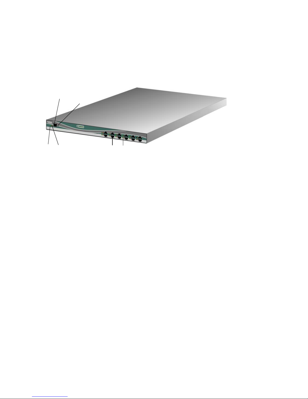
Figure 1 shows the front of the Edge Switch and identifies the front panel components.
4
132
5
6
1 Power LED (green)
2 Error LED (amber)
3 Ethernet LAN connector 10/100
4 Initial machine load (IML) button
5 SFP fiber optic connectors
6 Port LEDs
Figure 1 Edge Switch (front view)
The front panel of the Edge Switch includes the following connectors and indicators:
• Power (green) and Error (amber) LEDs
The Power LED illuminates when the Edge Switch is connected to facility AC power and is
powered on. If the LED extinguishes, a facility power source, power cord, or power distribution
failure is indicated.
The Error LED illuminates when the Edge Switch detects an event requiring immediate operator
attention, such as a FRU failure. The LED remains illuminated as long as an event is active. The
LED extinguishes when the Clear System Error Light function is selected from the Element
Manager. The LED blinks if unit beaconing is enabled. An illuminated Error LED (indicating a
failure) takes precedence over unit beaconing.
• Ethernet LAN connector
The Ethernet LAN connector is a 10/100 megabit per second (Mbps) RJ-45 twisted-pair
connector that attaches to an Ethernet LAN to provide communication with the HAFM Basic
interface or an SNMP management workstation. Two green LEDs are associated with the LAN
connector. When illuminated, the left LED indicates LAN operation at 10 Mbps, and the right
LED indicates LAN operation at 100 Mbps.
• Initial machine load (IML) button
When the IML button is pressed and held for three seconds, the Edge Switch performs an IML
procedure that takes approximately 30 seconds and resets the following:
• Microprocessor and functional logic for the control processor (CTP) (and firmware is loaded
from FLASH memory).
Edge Switch 2/12 installation guide 15
Page 16
• Ethernet LAN interface, causing the connection to the HAFM Basic interface to drop
momentarily until the connection automatically recovers.
• Ports, causing all Fibre Channel connections to drop momentarily until the connections
automatically recover.
An IML should be performed only if a CTP failure is indicated. Do not perform an IML on the
Edge Switch unless directed to do so by a procedural step in this manual or by the next level of
support. As a precaution, the IML button is flush mounted to protect against accidental
activation.
• SFP fiber-optic connectors
A single-mode or multimode fiber-optic cable attaches to a port through an SFP transceiver. The
SFP transciever provides a duplex LC interface and can be detached from the Edge Switch port
for easy replacement. Two fiber-optic transceiver types are available:
• Short-wave laser—Short-wave laser SFP transceivers provide short-distance connections (2 to
500 meters) through 50-micron or 62.5-micron multimode fiber.
• Long-wave laser—Long-wave laser SFP transceivers provide long-distance connections (up to
10 kilometers) through 9-micron single-mode fiber.
• Extended long-wave laser—Extended long-wave laser SFP transceivers provide long-distance
connections (up to 35 kilometers) through 9-micron single-mode fiber.
• Port LEDs
Amber and green/blue LEDs to the left of each Fibre Channel port illuminate, extinguish, or
blink to indicate port status and port speed:
• Amber LED illuminates to indicate a port failure.
• Green/blue LED illuminates:
• Green to indicate 1.0625 Gbps port operation
• Blue to indicate 2.125 Gbps port operation
Rear panel
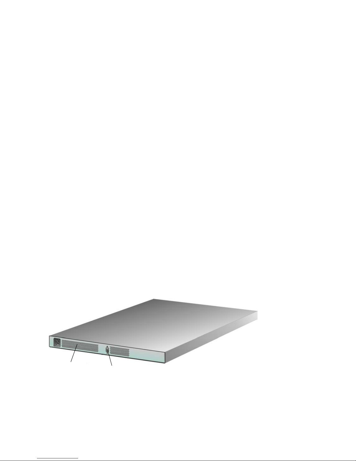
Figure 2 shows the rear of the Edge Switch and identifies its components.
1 Power supply with internal cooling fans 2 Maintenance port
Figure 2 Edge Switch (rear view)
Introduction to the Edge Switch 2/1216
1 2
Page 17
The rear panel of the Edge Switch includes the following:
• Power supply
The Edge Switch contains one power supply assembly with internal cooling fans. The power
supply assembly steps down and rectifies input power to provide 3.3 volts direct current (VDC),
5 VDC, and 12 VDC to the CTP card. The power supply also provides input filtering,
overvoltage protection, and overcurrent protection.
The power supply is input rated at 90 to 264 volts alternating current (VAC). Power supply
requirements are listed in ”Technical specifications” on page 73.
• Cooling fans
Three cooling fans (two integrated in the power supply assembly) provide cooling for the power
supplies and CTP card, as well as redundancy for continued operation if a single fan fails.
• Maintenance port
The rear panel provides a 9-pin RS-232 maintenance port that provides a connection for a local
terminal or dial-in connection for a remote terminal. Although the port is typically used by
authorized maintenance personnel, operations personnel can use the port to configure Edge
Switch network addresses.
Tools and test equipment
This section describes tools and test equipment that may be required to install, test, service, and
verify operation of the Edge Switch.
Tools supplied with the Edge Switch
The following tools are supplied with the Edge Switch. Use of the tools may be required to perform
one or more installation, test, service, or verification tasks.
• Loopback plug—An SFP multi-mode (short-wave laser) or single-mode (long-wave laser)
loopback plug, shown in Figure 3, is required to perform port loopback diagnostic tests. One
loopback plug is shipped with the Edge Switch, depending on the type of port transceivers
installed. Both plugs are shipped if short-wave laser and long-wave laser transceivers are
installed.
Figure 3 Loopback plug
Edge Switch 2/12 installation guide 17
Page 18
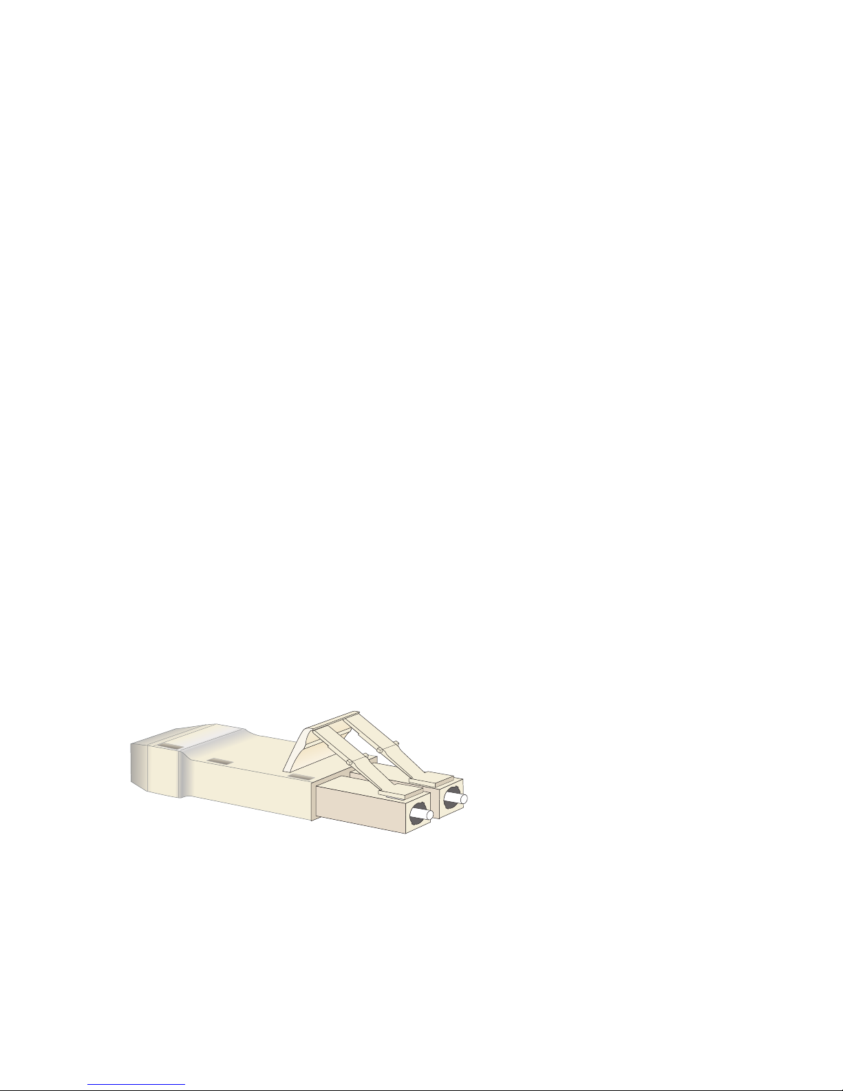
• Fiber-optic protective plug—For safety and port transceiver protection, fiber-optic protective
plugs, shown in Figure 4, must be inserted in all Edge Switch ports without fiber-optic cables
attached. The Edge Switch is shipped with protective plugs installed in all ports.
Figure 4 Fiber-optic protective plug
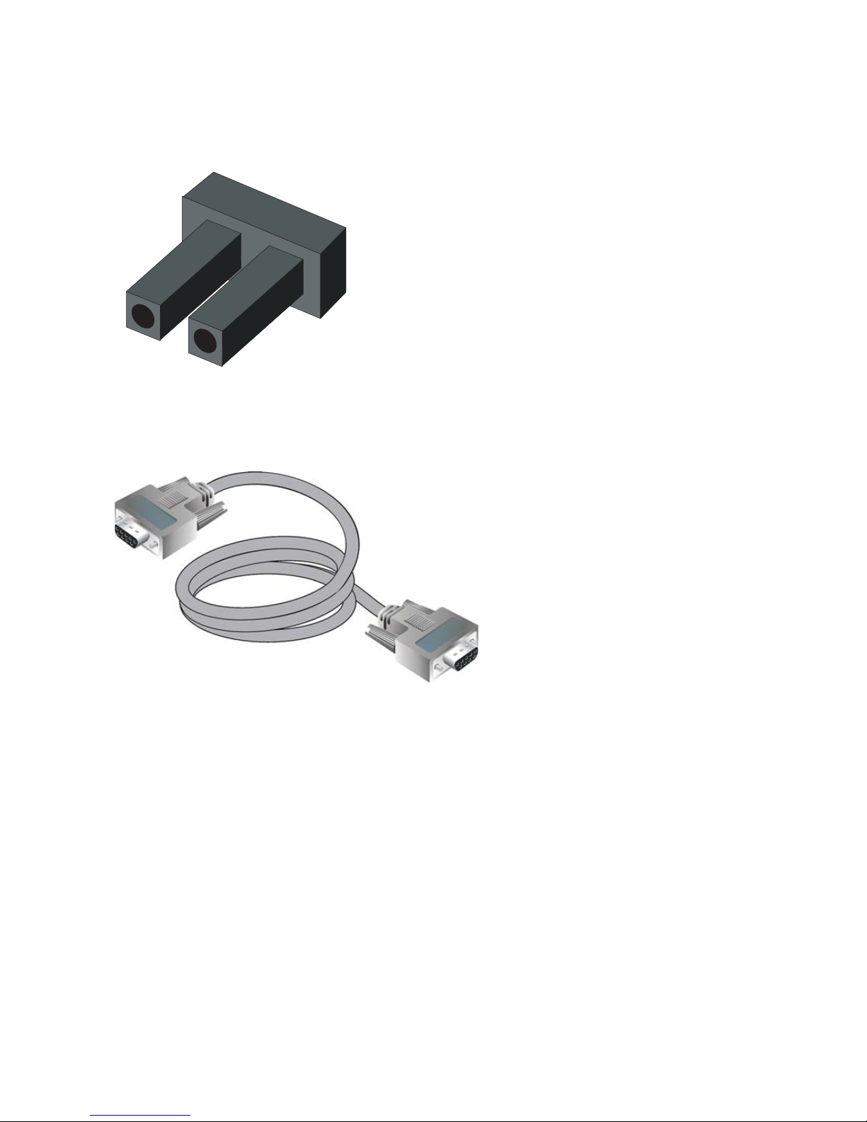
• Null modem cable—An asynchronous RS-232 null modem cable, shown in Figure 5, is required
to configure Edge Switch network addresses and acquire event log information through the
maintenance port. The cable has nine conductors and DB-9 male and female connectors.
Figure 5 Null modem cable
Tools supplied by service personnel
The following tools are expected to be supplied by service personnel performing Edge Switch
installation or maintenance actions. Use of the tools may be required to perform one or more test,
service, or verification tasks.
• Scissors or pocket knife—A sharp cutting edge may be required to cut the protective strapping
when unpacking replacement FRUs.
• Standard flat-tip and cross-tip (Phillips) screwdrivers—Screwdrivers are required to remove,
replace, adjust, or tighten various FRUs, chassis, or cabinet components.
• Electrostatic discharge (ESD) grounding cable with attached wrist strap—Use of the ESD wrist
strap is required when working in and around the Edge Switch card cage.
• Maintenance terminal (desktop or notebook PC)—A PC is required to configure Edge Switch
network addresses and acquire event log information through the maintenance port. The PC
must have:
Introduction to the Edge Switch 2/1218
Page 19

• The Microsoft
Millennium Edition operating system installed.
• RS-232 serial communication software (such as ProComm Plus or HyperTerminal) installed.
HyperTerminal is provided with Windows operating systems.
• Fiber-optic cleaning kit—The kit contains tools and instructions to clean fiber optic cable,
connectors, loopback plugs, and protective plugs.
Optional kits
Contact your HP-authorized service provider to purchase optional Edge Switch 2/12 kits described
in Table 2.
Table 2 Edge Switch 2/12 optional kits
Supporting Kit Description
®
Windows
®
98, Windows 2000, Windows Server 2003, Windows® XP, or
4-flexport upgrade for Edge Switch 2/12
Part Number: 348407-B21
Used to upgrade the Edge Switch 2/12 from:
• 4 to 8 ports
• 8 to 12 ports
E_Port (Full-Fabric) license for Edge Switch 2/12
Part Number: 348408-B21
300 m Optical Transceiver Kit
Part Number: 300834-B21
10 km Long-Distance Optical Transceiver Kit
Part Number: 300835-B21
Used to purchase E_Port licenses for
Edge Switch 2/12 Ports
Provides short-wave optical transceiver for the
Edge Switch 2/12
Provides 10 km long-wave optical transceiver for
the Edge Switch 2/12
NOTE: The E_Port (Full-Fabric) feature key is required to use the 10 km long-distance optical
transceiver. (See the HP StorageWorks Edge Switch Element Manager user guide for more
information about feature keys.)
Edge Switch 2/12 installation guide 19
Page 20

Introduction to the Edge Switch 2/1220
Page 21

2 Installing the Edge Switch
This chapter describes tasks required to install the Edge Switch. Some of the topics it covers include:
• Installation options, page 21
• Installation requirements, page 21
• Unpacking and inspecting the Edge Switch, page 22
• Installing the Edge Switch on a table or desktop, page 22
• Installing the Edge Switch in a rack, page 23
Installation options
The Edge Switch is installed in one of two configurations:
• Table or desktop—One or more switches can be installed at the customer facility on a desk or
table top.
• Customer-supplied equipment rack—One or more switches can be installed in a
customer-supplied equipment rack. Rack-mount hardware is provided in the shipping container.
NOTE: When using either configuration, you must consider Ethernet cabling, distance, and
LAN addressing issues.
Installation requirements
Ensure that the following requirements are met prior to Edge Switch installation:
• A site plan is prepared, configuration planning tasks are complete, planning considerations are
evaluated, and related planning checklists are complete. Also insure that Fabric and device
connectivity are evaluated, and the related planning worksheet is complete. See the HP
StorageWorks SAN high availability planning guide for more information.
• Browser-capable PC and Ethernet connectivity are available to support Edge Switch
management through the HAFM Basic interface.
• Support equipment and personnel are available for the installation.
• The required number and type of fiber-optic jumper cables are delivered and available. Ensure
that the cables are the correct length with the required connectors.
• Remote workstations or (optional) SNMP workstations are available. (Workstations are
customer-supplied and connected through a corporate or dedicated LAN.)
Verify that the following items are present before beginning installation:
• (Optional) An HP 9000, HP 10000, HP 11000, HP M-Series, HP rack system/e, or an
industry-standard 19-in rack.
• Torque driver with cross-tip bit (for setting 22 in./lb. of torque).
Edge Switch 2/12 installation guide 21
Page 22

• Fiber-optic protective plug—For safety and port transceiver protection, fiber-optic protective plugs
must be inserted in all Edge Switch ports without fiber-optic cables attached.
• Null modem cable—An asynchronous RS-232 null modem cable is required to configure Edge
Switch network addresses and obtain event log information through the maintenance port. The
cable has nine conductors and two DB-9 female connectors. A null modem cable specially
designed for this application is supplied with the Edge Switch.
• Standard flat-tip and cross-tip Phillips screwdrivers—Screwdrivers are required to remove,
replace, adjust or tighten various FRUs, chassis, or rack components.
• Electrostatic discharge (ESD) grounding cable with attached wrist strap—Use of the ESD wrist
strap is required when working in and around the Edge Switch card cage.
• Maintenance terminal (desktop or notebook computer)—A PC is required to configure Edge
Switch network addresses and acquire event log information through the maintenance port.
Computer requirements include:
• Microsoft Windows 98, Windows Millennium Edition, Windows 2000, Windows Server
2003, or Windows XP operating system installed.
• RS-232 serial communication software (for example, ProComm Plus, or HyperTerminal).
Unpacking and inspecting the Edge Switch
To unpack and inspect the Edge Switch:
1. Inspect the shipping containers for damage caused during transit. If a container is damaged,
ensure a representative from the freight carrier is present when the container is opened.
2. Unpack the shipping containers and inspect each item for damage. Save all shipping and
packing materials. Ensure that all items on the enclosed shipping list are in each container.
3. If any items are damaged or missing, contact an HP-authorized service provider or reseller.
Installing the Edge Switch on a table or desktop
To install and configure the Edge Switch on a table or desktop:
1. Remove the backing from the four adhesive rubber pads and apply the pads to the underside of
the Edge Switch. Ensure that the pads are aligned with the scribed circles at each corner.
2. Position the Edge Switch on a table or desktop as directed by the customer. Ensure:
• Grounded AC electrical outlets are available.
• Adequate ventilation is present.
• Areas with excessive heat, dust, or moisture are avoided.
• All planning considerations are met. See the HP StorageWorks SAN high availability
planning guide.
3. Verify that all FRUs are installed as ordered.
4. Verify that the SFP optical transceivers are installed as required for your installation.
5. Connect the U.S. or country-specific (optional) AC power cord to the rear of the chassis.
Installing the Edge Switch22
Page 23

WARNING! An HP-supplied power cord is provided for each Edge Switch power supply. To
prevent electric shock when connecting the Edge Switch to primary facility power, use only the
supplied power cords, and ensure that the facility power receptacle is the correct type, supplies the
required voltage, and is properly grounded.
6. Connect the remaining end of the AC power cord to a power source that provides single-phase,
120 to 240 volt alternating current (VAC).
7. Turn on the power.
The unit powers on and performs power-on self-tests (POSTs). During POSTs:
• The green power (PWR) LED on the front panel turns on.
• The amber system error (ERR) LED on the front panel flashes momentarily while the Edge
Switch is tested.
• The green LEDs associated with the Ethernet port flash momentarily while the port is tested.
• The green/blue and amber LEDs associated with the ports flash momentarily while the ports
are tested.
After successful POST completion, the green power (PWR) LED remains on and all other front
panel LEDs turn off.
8. If a POST error or other malfunction occurs, see the Edge Switch service manual to isolate the
problem.
Installing the Edge Switch in a rack
This section describes how to mount the Edge Switch in one of the following rack types:
• HP 9000 series, 10000 series, or 11000 series
• HP rack system/e or 19-inch EIA
Rack mount checklist
This section describes the contents of the rack mount kit as well as tools or equipment required to
complete the installation.
NOTE: The hardware kit includes parts not required for the configuration described in these
instructions.
Mounting hardware
• Two two-hole bar nuts
• Six three-hole bar nuts (only four used)
• Eight square alignment washers (required only for HP 9000, 10000 and 11000 series racks)
• Eight Phillips panhead screws (10-32 x 1/2) with split lock and flat washers
• Four Phillips flathead screws (8-32 x 7/16)
Edge Switch 2/12 installation guide 23
Page 24
• Ten Phillips panhead screws (10-32 x 5/8) with flat washer (only 2 used)
• Six Phillips flathead screws (6-32 x 3/8) (not used)
• Twelve Phillips panhead screws (10-32 x 3/8) (not used)
• Four 8-32 Keps nuts (not used)
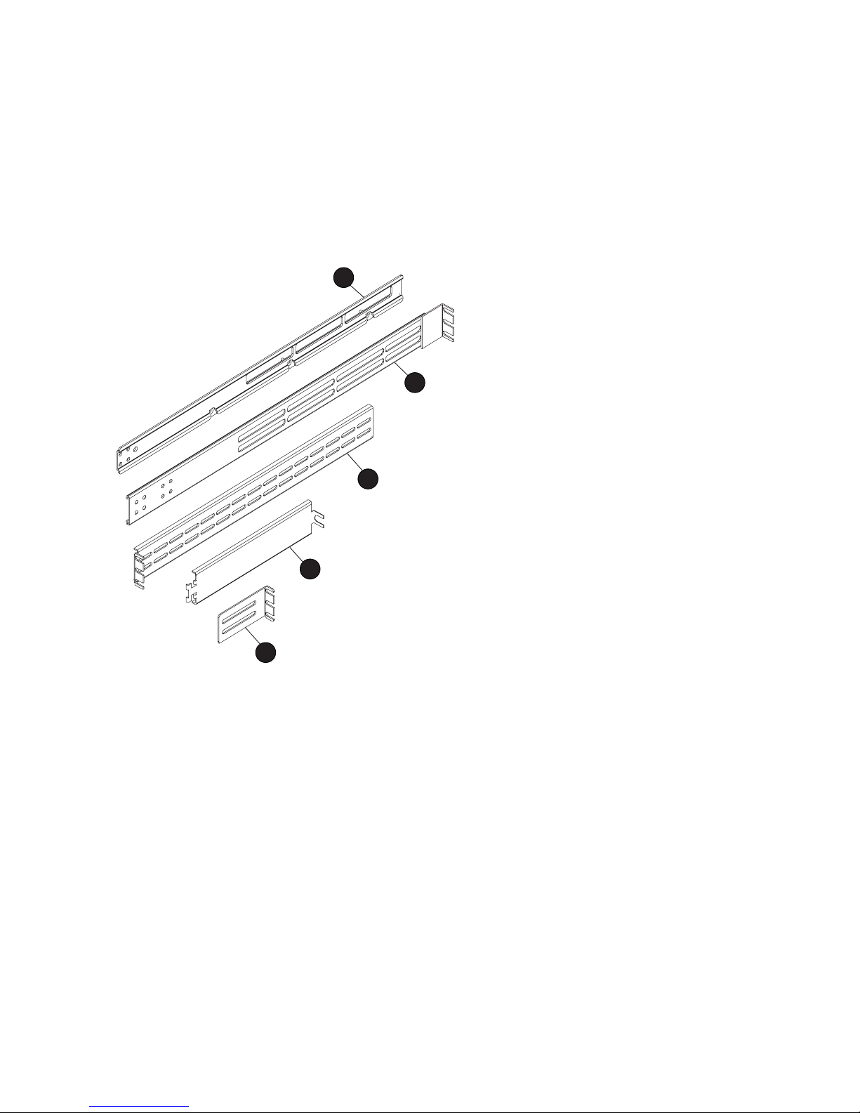
Brackets and rails
Figure 6 shows the brackets and rails included in the rack mount kit.
1
2
3
4
5
1 Two fixed-length slide rails (one left
and one right)
2 Two front brackets
3 Two rear brackets (long)
4 Two rear spacing brackets
5 Rear bracket (short)---not used in this
configuration
Figure 6 Brackets included in kit
Required tools
The following tools are required, but are not included in the kit:
• Torque driver with a T10 Torx bit
• #2 Phillips screwdriver
Mounting the adjustable brackets in the rack
Tools and equipment required:
• One #2 Phillips screwdriver
Installing the Edge Switch24
Page 25

• Eight 10x32 panhead screws
• Eight square alignment washers if you are installing the Edge Switch in an HP 9000, 10000, or
11000 series rack
To install the adjustable brackets on the rack:
1. Determine the position of the Edge Switch in the rack.
Each Edge Switch is 1.75 inches or 1U high.
2. Attach four (three-hole) bar nuts to the cabinet frame using eight Phillips panhead screws
(10-32 x 1/2) with split lock and flat washers.
NOTE: Do not install a screw in the center hole of each bar nut.
3. If you are installing the Edge Switch in an HP 9000, 10000, or 11000 series rack, place a
square alignment washer on each panhead screw before inserting in the square cabinet frame
holes:
a. Mount the bar nut on the inside of the cabinet frame. Orient the holes in the bar nut so that
they are aligned closest to the inside edge of the cabinet frame.
b. Secure, but do not completely tighten, all screws.
4. Measure cabinet depth from inside edge to inside edge of the cabinet frame.
5. Assemble two sets of front and rear brackets so that the combined brackets are equal to the
depth of the cabinet.
6. Attach a two-hole bar nut using four Phillips flathead screws (8-32 x 7/16) to hold each
assembled bracket together. Do not completely tighten the screws but tighten them enough to
hold the brackets together.
7. Install the assembled brackets in the cabinet by sliding the mounting brackets between the bar
nut and cabinet frame.
8. Tighten the three-hole bar nut screws on the mounting brackets until the rails are stable, but can
be easily adjusted.
9. Securely tighten the two-hole bar nut screws holding the front and rear brackets together.
NOTE: If you are installing the Edge Switch in an HP rack system/e, complete step 10.
10.Attach another two-hole bar nut at the rear of the last vent slot using four Phillips flathead screws
(8-32 x 7/16) to stabilize the inside ends of the rear brackets.
Mounting the slide rails on the sides of the Edge Switch
Tools and equipment required:
• A torque driver with a T10 Torx bit (not supplied in the kit)
• Left and right slide rails
To install the slide rails on the sides of the Edge Switch (Figure 7):
Edge Switch 2/12 installation guide 25
Page 26

1. On the Edge Switch, remove the six screws (three screws per side) that help hold the Edge Switch
cover in place.
NOTE: Do not discard these screws, as you will use them to attach the slide rails.
2. Using the torque driver and the screws you removed earlier, attach the left and right slide rails to
the Edge Switch.
Figure 7 Attaching the slide rail to the Edge Switch
Installing the Edge Switch in the cabinet
Tools and equipment required:
• One #2 Phillips screwdriver
• Two rear spacing brackets
To install the Edge Switch in the cabinet:
1. From the front side of the cabinet, slide the Edge Switch into the mounting brackets and along
the rails until the rear of the Edge Switch is flush with the rear of the cabinet.
2. Bring the rear spacing brackets to the rear of the cabinet.
3. Pull the Edge Switch toward the rear of the cabinet until it protrudes approximately 3 inches.
4. Orient the rear spacing bracket mounts so that they are pointed outward. Insert the tabs on each
rear spacing bracket into the designated slots in each rail.
5. Push the Edge Switch forward using both rear spacing brackets until the rear spacing bracket
mounts contact the cabinet rail.
6. Attach the rear spacing brackets to the cabinet using two Phillips panhead screws (10-32 x 5/8)
with flat washers.
Ensuring that the square alignment washers are seated properly within the square cabinet frame
holes, use a Phillips head screwdriver to tighten the rear and front mounting screws.
Installing the Edge Switch26
Page 27

3 Connecting the Edge Switch
This chapter describes required steps to connect, configure, and verify operation of the Edge Switch.
Some of the topics it covers include:
• Edge Switch network addresses, page 27
• LAN-connecting the Edge Switch, page 31
Edge Switch network addresses
The Edge Switch is delivered with the following default network addresses:
• MAC address—The media access control (MAC) address is programmed into FLASH memory
on the CTP card at the time of manufacture. The MAC address is unique for each Edge Switch,
and should not be changed. The address is in xx.xx.xx.xx.xx.xx format, where xx is a
hexadecimal pair.
NOTE: References to the CTP in this manual are to the control processor logic contained on
the Edge Switch motherboard. If an event occurs that indicates the CTP is faulty, replacement
of the Edge Switch assembly is required.
• IP address—The factory preset default IP address is 10.1.1.10.
If multiple switches are installed on the same LAN, each Edge Switch must have a unique IP
address. One Edge Switch can use the factory-set address, but the addresses of the remaining
switches must be changed.
• Subnet mask—The default subnet mask is 255.0.0.0. If the Edge Switch is installed on a
complex public LAN with one or more routers, the address may need to be changed.
• Gateway address—The default gateway address is 0.0.0.0. If the Edge Switch is installed on a
dedicated LAN with no connection through a router, the address does not need to be changed.
If the Edge Switch is installed on a public LAN (corporate intranet), the gateway address must be
changed to the address of the corporate intranet’s local router.
Verify the type of LAN installation with the customer’s network administrator. If one Edge Switch is
installed on a dedicated LAN, network addresses do not need to be changed.
Changing the Edge Switch addresses
If multiple switches are installed or a public LAN segment is used, network addresses must be
changed to conform to the customer’s LAN addressing scheme. The following items are required to
perform this task:
• A local workstation (desktop or notebook computer) with:
• Microsoft Windows 98, Windows 2000, Windows Server 2003, Windows Millennium
Edition, or Windows XP operating system
• RS-232 serial communication software (for example, ProComm Plus or HyperTerminal)
Edge Switch 2/24 installation guide 27
Page 28

• An asynchronous RS-232 null modem cable (provided with the Edge Switch)
To change an Edge Switch’s IP address, subnet mask, or gateway address:
1. Remove the protective metal plate from the 9-pin maintenance port at the rear of the Edge Switch
(a Phillips-tip screwdriver is required). Connect the 9-pin end of the RS-232 null modem cable to
the port.
2. Connect the other cable end to a 9-pin communication port (COM1 or COM2) at the rear of the
workstation.
3. Power on the workstation.
After the workstation powers on, the Windows desktop is displayed. See the operating
instructions shipped with the PC for additional information.
4. Select Start > Programs > Accessories > Communications > HyperTerminal.
The Connection Description dialog box is displayed (Figure 8).
Figure 8 Connection Description dialog box
5. Enter edge switch 2-12 in the Name box and click OK.
The Connect To dialog box is displayed (Figure 9).
Figure 9 Connect To dialog box
Connecting the Edge Switch28
Page 29

6. Ensure that the Connect using box displays COM1 or COM2 (depending on the serial
communication port connection to the Edge Switch), and click OK.
The Port Settings dialog box is displayed (Figure 10).
Figure 10 Port Settings dialog box
7. Enter the Port Settings parameters as follows:
•Bits per second—115200
• Data bits—8
•Parity—None
• Stop bits—1
• Flow control—Hardware or None
When the parameters are set, click OK.
The HyperTerminal window is displayed.
8. At the > prompt, enter the user-level password (the default is password) and press Enter.
Edge Switch 2/24 installation guide 29
Page 30

The password is case sensitive. The HyperTerminal window is displayed with a C> prompt at
the top of the window (Figure 11).
Figure 11 HyperTerminal window
9. At the C> prompt, enter ipconfig and press Enter.
The HyperTerminal window is displayed with configuration information listed as follows:
• MAC Address
• IP Address (default is 10.1.1.10, factory preset is 10.1.1.10)
• Subnet Mask (default is 255.0.0.0).
• Gateway Address (default is 0.0.0.0)
Only the IP Address, Subnet Mask, and Gateway Address are configurable.
10.Change the IP address, subnet mask, and gateway address as directed by the network
administrator. To change Edge Switch network addresses, enter the following at the C> prompt:
ipconfig xxx.xxx.xxx.xxx yyy.yyy.yyy.yyy zzz.zzz.zzz.zzz
The IP address is always xxx.xxx.xxx.xxx, the subnet mask is always
yyy.yyy.yyy.yyy, and the gateway address is always zzz.zzz.zzz.zzz. The octets xxx,
yyy, and zzz are decimals from zero through 255. If a network address is to remain
unchanged, type the current address in the respective field.
When the new network addresses are configured at the Edge Switch, the message Request
completed OK is displayed at the bottom of the HyperTerminal window.
11.Select File > Exit to close the HyperTerminal application.
A message box is displayed (Figure 12).
Figure 12 Disconnect Now dialog box
Connecting the Edge Switch30
Page 31

12.Click Yes.
A message box is displayed (Figure 13).
Figure 13 Save Session dialog box
13.Click No to exit and close the HyperTerminal application.
14.Power off the workstation:
a. Select Start > Shut Down.
The Shut Down Windows dialog box is displayed.
b. Select Shut Down Windows > Shut down the Computer and click Yes to power off the
workstation.
15.Disconnect the RS-232 null modem cable from the Edge Switch and the workstation.
16.Replace the protective metal plate over the maintenance port.
LAN-connecting the Edge Switch
To connect the Edge Switch to the Ethernet LAN segment or the HP-supplied Ethernet hub:
1. Connect one end of the Ethernet patch cable (supplied with the Edge Switch) to the RJ-45
connector (labeled 10/100) on the left front of the chassis.
2. Connect the remaining end of the Ethernet cable to the LAN as follows:
• If the Edge Switch is installed on a customer-supplied LAN segment, connect the cable to the
LAN as directed by the customer’s network administrator.
• If the Edge Switch is installed on the HP-supplied Ethernet hub, connect the cable to any
available port on the hub.
3. To manage the Edge Switch through the HAFM Basic interface, attach the Ethernet LAN segment
to a web browser-capable computer and go to ”Using the HAFM Basic interface” on page 35.
Connecting cables to Fibre Channel ports
Perform this proceedure to connect devices to the Edge Switch:
1. Route single-mode or multimode fiber-optic cables (depending on the type of SFP pluggable
optic transceivers installed) from the desired devices to ports at the front of the Edge Switch.
2. Connect device cables to SFP transceivers.
3. Perform one of the following:
• If the Edge Switch is installed on a table or desk top, bundle and secure the Fibre Channel
cables as directed by the customer.
• If the Edge Switch is installed in an HP-supplied equipment rack, bundle Fibre Channel
cables from the Edge Switch and other equipment (groups of 16 maximum), and secure them
as directed by the customer.
4. Set the Edge Switch online.
Edge Switch 2/24 installation guide 31
Page 32

Connecting the Edge Switch32
Page 33

4 Using the HAFM Basic interface
Use the HAFM Basic interface to configure the Edge Switch 2/12. Selectively perform the following
configuration tasks according to your installation requirements:
• Launching the HAFM Basic interface, page 35
• Setting the Edge Switch offline and online, page 37
• Configuring Edge Switch ports, page 37
• Configuring BB credit, page 39
• Configuring Edge Switch identification, page 40
• Configuring date and time, page 41
• Configuring Edge Switch parameters, page 42
• Configuring network information, page 45
• Configuring SNMP trap message recipients, page 46
• Enabling or disabling the CLI, page 48
• Configuring zoning, page 54
• Connecting the Edge Switch to a fabric, page 54
NOTE: This chapter describes the initial set up of the Edge Switch using the HAFM Basic interface.
For additional information on configuring advanced features using HAFM Basic interface, see the
HAFM Basic online help or the HAFM Basic user guide.
Launching the HAFM Basic interface
Use the following steps to launch the HAFM Basic interface:
NOTE: Internet access and a standard web browser is required. HP recommends Netscape
Navigator 4.6 or higher or Microsoft Internet Explorer 4.0 or higher.
1. Ensure that the browser-capable PC and the Ethernet LAN segment (with the Edge Switch
attached) are connected.
2. At the PC, launch the browser (Netscape Navigator
or Internet Explorer).
Edge Switch 2/12 installation guide 35
Page 34

3. At the browser, enter the IP address of the Edge Switch as the internet Uniform Resource Locator
(URL). Use the default IP address of 10.1.1.10 or the IP address configured while performing
”Configuring network information” on page 45.
The Enter Network Password dialog box is displayed (Figure 14).
Figure 14 Enter Network Password dialog box
4. Enter the default user name and password.
The First Time Login view displays.
NOTE: The default user name is Administrator and the default password is password. The user
name and password are case-sensitive.
5. Enter the customer-specified values in the User Name, New Password, and Confirm Password
boxess, and then click Activate.
The Topology view appears with status information about each fabric element, including the
product to be configured.
6. Click Switch Details.
The Hardware view is displayed (Figure 15).
7. You can configure the product from the HAFM Basic interface. From the menu bar at the top of
the view, selectively configure the following information according to customer requirements:
• Product—Includes identification, date and time, parameters, fabric parameters, and network
addresses.
• Ports—Includes basic information, buffer-to-buffer credits (BB_Credits), and N_Port identifier
virtualization (NPIV).
• Management—Includes SNMP trap message recipients, command line interface (CLI), open
systems management server (OSMS), and secure socket layer (SSL) encryption.
• Options—Includes product feature enablement (PFE) keys.
Using the HAFM Basic interface36
Page 35

• Interswitch links—Includes preferred path and interswitch link (ISL) port fencing.
Figure 15 HAFM Basic interface—Hardware view
Setting the Edge Switch offline and online
To configure some Edge Switch settings, you must set the Edge Switch offline. Once you have
configured the settings, you need to set the Edge Switch back online again.
To set the Edge Switch offline:
• Select Configure > Switch Offline.
The following message is displayed:
Your operations changes have been successfully activated
To set the Edge Switch online:
• Select Configure > Switch Online.
The following message is displayed:
Your operations changes have been successfully activated
Configuring Edge Switch ports
To configure ports, there are three dialog boxes:
• Basic Information—Enables you to configure basic aspects of a port, such as the ports name,
the blocked status, the Fabric Address Notification (FAN) status, the port type, and the port
speed.
• Rx BB Credit—Enables you to configure receive BB_Credits for a port.
• NPIV—Enables you to configure and enable N_Port ID Virtualization (NPIV) functionality for
a port. Perform the procedure in this section to configure names and operating characteristics
for the Edge Switch ports.
To configure the basic port information:
1. Select Configure > Ports > Basic Information.
Edge Switch 2/12 installation guide 37
Page 36

The Port Basic Information dialog box is displayed (Figure 16).
Figure 16 Basic Information dialog box
a. For each port to be configured, enter a port name of 24 or fewer alphanumeric characters in
the associated Name box.
The port name should identify the device to which the port is attached.
NOTE: If you want to select another port, enter the port number in the Jump to Port box and
then click go.
b. Select or clear the check box in the Blocked column to block or unblock a port (default is
unblocked).
c. A check mark in the check box indicates the port is blocked. Blocking a port prevents the
attached device from communicating with the Edge Switch. A blocked port continuously
transmits the offline sequence (OLS).
d. Select or clear the check box in the FAN column to enable or disable the fabric address
notification (FAN) feature (default is enabled).
A check mark in the check box indicates FAN is enabled. When the feature is enabled, the
port transmits a FAN frame after loop initialization to verify that FC-AL devices are still
logged in. HP recommends enabling this option for ports configured for loop operation.
e. Select the port type from the Type list.
Available selections are:
• Generic mixed port (GX_Port)---Use this selection to configure a port as a generic loop
port (GL_Port). This selection is available only if enabled through an optional feature key.
Using the HAFM Basic interface38
Page 37

(For more information about feature keys, see the HP StorageWorks Edge Switch Element
Manager user guide.)
• Fabric mixed port (FX_Port)---Use this selection to configure a port as a fabric loop port
(FL_Port).
• Generic port (G_Port)---This selection is available only if enabled through an optional
feature key. (For more information about feature keys, see the HP StorageWorks Edge
Switch Element Manager user guide.)
•Fabric port (F_Port).
• Expansion port (E_Port)---This selection is available only if enabled through an optional
feature key. (For more information about feature keys, see the HP StorageWorks Edge
Switch Element Manager user guide.)
NOTE: On the 12-Port Switch, the E_Port, G_Port, and GX_Port options are not valid, unless the
Fabric Capable feature is enabled. For more information, see the McDATA Sphereon 4300 Switch
Installation and Service Manual.
f. Select the port speed from the Speed list to configure the port transmission rate.
Available selections are:
• Negotiate—Auto-negotiate between 1.0625 and 2.125 gigabit per second (Gbps)
operation. This is valid only on products that are capable of 2 Gbps operation. This is the
default selection.
• 1 Gb/sec—1.0625 Gbps operation.
• 2 Gb/sec—2.125 Gbps operation.
2. Click OK to save the information
The following message is displayed:
Your changes have been successfully activated
3. If the port is offline, set the port online (see ”Setting the Edge Switch offline and online” on
page 37.
Configuring BB credit
For each type of port, there is a maximum and minimum BB credit limit, which is displayed as a
range.
As you enter the BB credit value, the value is validated and an error message is displayed for each
port if applicable. The BB credit configuration is not activated if there are any outstanding errors.
To configure BB credits:
1. Set the port offline (see ”Setting the Edge Switch offline and online” on page 37).
2. Select Configure > Ports > Rx BB Credit.
The Rx BB Credit view is displayed.
Edge Switch 2/12 installation guide 39
Page 38

TIP: Use the Windows vertical scroll bar to display additional port information rows.
3. Click Default to select the default values.
A confirmation message is displayed.
4. Click OK to accept the default values.
NOTE: HP recommends that you use the default values. If they are not appropriate, you can
enter values in the RX BB Credit box.
NOTE: If you want to select another port, enter the port number in the Jump to Port box and
then click go.
5. Click OK to save the changes.
6. Place the port back online (see ”Setting the Edge Switch offline and online” on page 37).
Configuring Edge Switch identification
Perform this procedure to configure the Edge Switch name, description, location, and contact
person. The Name, Location, and Contact variables configured here correspond respectively to
the SNMP variables sysName, sysLocation, and sysContact. These variables are used by
SNMP management workstations when obtaining data from managed switches.
To configure the Edge Switch identification:
1. Select Configure > Switch > Identification.
The Identification view is displayed (Figure 17).
Figure 17 Identification view
a. Enter an Edge Switch name of 24 or fewer alphanumeric characters in the Name box.
Each Edge Switch should be configured with a unique name.
Using the HAFM Basic interface40
Page 39

If the Edge Switch is installed on a public LAN, the name should reflect the Edge Switch’s
Ethernet network DNS host name. For example, if the DNS host name is hpes212.hp.com,
enter hpes212.
b. Enter an Edge Switch description of 255 or fewer alphanumeric characters in the Description
box.
c. Enter the Edge Switch physical location (255 or fewer alphanumeric characters) in the
Location box.
d. Enter the name of a contact person (255 or fewer alphanumeric characters) in the Contact
box.
2. Click OK to save the information.
The following message is displayed:
Your changes have been successfully activated
Configuring date and time
Perform this procedure to configure the effective date and time for the Edge Switch.
1. Select Configure > Switch > Date & Time.
The Date Time view is displayed (Figure 18).
Figure 18 Date Time view
a. Click the Date boxes that require change, and enter numbers in the following ranges:
Month (MM): 1 through 12
Day (DD): 1 through 31
Year (YYYY): greater than 1980
b. Click the Time boxes that require change, and enter numbers in the following ranges:
Hour (HH): 0 through 23
Minute (MM): 0 through 59
Second (SS): 0 through 59
2. Click OK to save the information.
The following message is displayed.
Your changes have been successfully activated
Edge Switch 2/12 installation guide 41
Page 40

Configuring Edge Switch parameters
Perform this procedure to configure the following Edge Switch and fabric operating parameters:
Buffer-to-Buffer Credit (BB_Credit), Error Detect Time Out Value (E_D_TOV), Resource Allocation
Time Out Value (R_A_TOV), preferred domain ID and switch priority.
To configure Edge Switch parameters:
1. Set the Edge Switch offline (see ”Setting the Edge Switch offline and online” on page 37).
2. Select Configure > Switch > Parameters.
The Parameters view is displayed (Figure 19).
NOTE: The Insistent Domain ID is not supported on the Edge Switch 2/12. Selecting or
clearing the Insistent Domain ID has no effect.
Figure 19 Parameters view
3. Set the Edge Switch parameters:
c. Select (enable) or clear (disable) the Rerouting Delay check box.
If rerouting delay is enabled, traffic is delayed through a fabric by the specified E_D_TOV
time. This delay ensures Fibre Channel frames are delivered to their destination in order, even
if a change to the fabric topology creates a new (shorter) transmission path.
d. Select (enable) or clear (disable) the Domain RSCN check box.
Domain register for state change notifications (domain RSCNs) are sent between end devices
in a fabric to provide additional connection information to HBAs and storage devices. For
example, this information might be that a logical path has been broken because of a
physical event, such as a fiber optic cable being disconnected from a port. Consult with your
HBA and storage device vendor to determine if enabling Domain RSCNs will cause
problems with your HBA or storage products.
Using the HAFM Basic interface42
Page 41

e. Select (enable) or clear (disable) the Suppress RSCN on Zone Set Activations check box.
When the parameter is enabled, attached devices do not receive notification following any
change to the fabric's active zone set.
When the parameter is disabled, attached devices (registered through the fabric format
domain register) do receive notification following any change to the fabric's active zone set.
f. Select (enable) or clear (disable) the Limited Fabric RSCN check box.
When enabled, RSCNs are not transmitted after a product initial program load (IPL).
g. Select (enable) or clear (disable) the Zone Flexpars: Isolate Fabric RSCNs on zone activation
changes check box.
When enabled, zone FlexPars isolate and prevent fabric-format RSCNs from propagating to
devices in zones that are not impacted.
h. Enter a value from 1 through 31 (default is 1) in the Preferred Domain ID box.
The domain ID uniquely identifies each switch in a fabric.
NOTE: All fabric-attached switches must have a unique domain ID. If the value is not
unique, the E_Port connection to the switch segments and the switch cannot communicate
with the fabric.
i. Select By Port Speed or Ignore Port Speed from the ISL FSPF Cost Configuration drop-down
list.
• By Port Speed—The fastest fabric path is determined by port (ISL) speed. Cost is inversely
proportional to speed.
• Ignore Port Speed—ISL speed is ignored, and the fastest fabric path is determined by the
number of hops. Cost is directly proportional to hop count.
4. Click OK to save the information.
The following message is displayed:
Your changes have been successfully activated
5. Set the Edge Switch online (see ”Setting the Edge Switch offline and online” on page 37).
To configure fabric parameters:
1. Set the Edge Switch offline (see ”Setting the Edge Switch offline and online” on page 37).
2. Select Configure > Switch > Fabric Parameters.
The Fabric Parameters view is displayed (Figure 20).
Edge Switch 2/12 installation guide 43
Page 42

Figure 20 Fabric Parameters view
3. Set the fabric parameters:
a.
Enter a value from 10 through 1200 tenths of a second (one through 120 seconds) in the
R_A_TOV box.
The default is 10 seconds (100 tenths).
NOTE: All fabric-attached switches must be set to the same R_A_TOV. If the value is not
compatible, the E_Port connection to the switch segments and the switch cannot
communicate with the fabric. In addition, the R_A_TOV must be greater than the E_D_TOV.
b. Enter a value from 2 through 600 tenths of a second (0.2 through 60 seconds) in the
E_D_TOV box.
The default is 20 tenths of a second (2 seconds).
NOTE: All fabric-attached switches must be set to the same E_D_TOV. If the value is not
compatible, the E_Port connection to the switch segments and the switch cannot
communicate with the fabric. In addition, the E_D_TOV must be less than the R_A_TOV.
c. Select Principal, Never Principal, or Default in the Switch Priority box.
The default setting is Default. The switch priority value designates the fabric’s principal
switch. The principal switch controls the allocation and distribution of domain IDs for all
fabric Directors and Edge Switches (including itself).
d. Select one of the following from the Interop Mode drop-down list:
• Homogeneous Fabric—Select this mode if the fabric contains only HP Edge Switches and
Directors that are operating in Homogeneous Fabric mode.
• Open Fabric 1.0—Select this mode if the fabric contains HP Directors and Edge Switches,
as well as other open-fabric compliant switches. Select this mode for managing
heterogeneous fabrics.
4. Click OK to save the information.
Using the HAFM Basic interface44
Page 43

The following message is displayed:
Your changes have been successfully activated
5. Set the Edge Switch online (see ”Setting the Edge Switch offline and online” on page 37).
Configuring network information
The way in which you configure network information depends on the type of LAN installed at your
facility:
• If one Edge Switch is installed on a dedicated LAN, network information (IP address, subnet
mask, and gateway address) does not require change. Go to ”Configuring Edge Switch ports”
on page 37.
• If multiple Edge Switches are installed or a public LAN segment is used, network information
must be changed to conform to your LAN addressing scheme. Perform one of the following:
• If network information was changed while performing”Edge Switch network addresses” on
page 27, go to ”Configuring SNMP trap message recipients” on page 46.
• If network information was not changed, perform the procedure that follows.
To change an Edge Switch IP address, subnet mask, or gateway address:
1. Select Configure > Switch > Network.
The Network view is displayed (Figure 21).
Figure 21 Network view
2. Make the following entries:
a. Enter the new value specified by the network administrator in the IP Address box.
Default is 10.1.1.10.
b. Enter the new value specified by the network administrator in the Subnet Mask box.
Default is 255.0.0.0.
c. Enter the new value specified by the network administrator in the Gateway Address box.
Default is 0.0.0.0.
Edge Switch 2/12 installation guide 45
Page 44

3. Click OK to save the information.
An acknowledgement message is displayed, indicating the browser PC must be directed to the
new IP address.
4. Update the address resolution protocol (ARP) table for the browser PC:
a. Select File > Close to close the HAFM Basic and browser applications.
The Windows desktop is displayed.
b. Select Start > Programs > Command Prompt.
A disk operating system (DOS) window is displayed.
c. Delete the Edge Switch’s old IP address from the ARP table as follows:
At the command (C:\) prompt, enter arp —d xxx.xxx.xxx.xxx, where
xxx.xxx.xxx.xxx is the old IP address for the Edge Switch.
d. Click close (X) at the upper right corner of the DOS window to close the window and return
to the Windows desktop.
5. Press and hold the IML/RESET button on the product front panel for ten seconds to perform a
power-on reset (POR).
6. Launch the browser application on the PC (Netscape Navigator
7. Enter the Edge Switch’s new IP address as the Internet URL in the browser.
The Enter Network Password dialog box is displayed.
8. Enter the default user name and password.
or Internet Explorer).
NOTE: The default user name is Administrator and the default password is password.
The user name and password are case-sensitive.
9. Click OK.
The HAFM Basic interface opens with the View window displayed.
Configuring SNMP trap message recipients
Perform this procedure to configure community names, write authorizations, and network addresses
for up to 6 SNMP trap message recipients per Edge Switch. A trap recipient is a management
workstation that receives notification (through SNMP) if a switch event occurs.
1. Select Configure > SNMP.
Using the HAFM Basic interface46
Page 45

The SNMP view is displayed (Figure 22).
Figure 22 SNMP view
2. Perform the following:
a. Click the Enable or Disable button to enable or disable the installed SNMP agent.
b. Select the Fibre Alliance management information base (FA MIB) from the FA MIB Version
drop-down list. This should be set to match the level of FA MIB used by the SNMP
management stations that access the product. Available selections are:
•FA MIB 3.0
•FA MIB 3.1
c. Select or clear the Enable Authentication Traps check box to enable or disable transmission
of SNMP trap messages to configured recipients.
d. For each trap recipient to be configured, enter a community name of 32 or fewer
alphanumeric characters in the associated Name box.
The community name is incorporated in SNMP trap messages to ensure against
unauthorized viewing or use.
e. Select or clear the Write Auth check box to enable or disable write authorization for the trap
recipient.
A check mark in the box indicates write authorization is enabled (default is disabled). When
the feature is enabled, a management workstation user can change the sysContact,
sysName, and sysLocation SNMP variables.
f. Enter the IP address or DNS host name of the trap recipient (SNMP management
workstation) in the associated Trap Recipient box. Use 64 or fewer alphanumeric characters.
HP recommends using the IP address.
g. Enter a decimal user datagram protocol (UDP) number in the UDP Port box.
The default is 162.
Edge Switch 2/12 installation guide 47
Page 46

3. Click OK to save the information.
The following message is displayed:
Your changes have been successfully activated
Enabling or disabling the CLI
Perform this procedure to enable or disable the Edge Switch’s command line interface.
1. Click Configure > CLI.
The CLI view is displayed (Figure 23).
Figure 23 CLI view
2. Click the Enable or Disable button to enable or disable the CLI.
3. Select the Use SSH check box to enable secure shell (SSH).
The SSH protocol controls CLI access to the product and provides software-enforced encryption.
NOTE: The default protocol value is Telnet, which means that data is not encrypted between
the user and the product. By selecting SSH, data, such as a user ID and password, is
encrypted between the user and the product.
4. Click OK.
The following message is displayed:
Your changes have been successfully activated
Enabling or disabling OSMS and host control
Perform this procedure to enable or disable host control of the Edge Switch through the Open
System Management Server (OSMS). The OSMS is a keyed feature that allows host control and
inband management of an Edge Switch through a management application that resides on an
open-systems interconnection (OSI) device. This device is attached to a Director or Edge Switch port.
The device communicates with the Edge Switch or Director through the Fibre Channel common
transport (FC-CT) protocol.
1. Click Configure > OSMS.
Using the HAFM Basic interface48
Page 47

The OSMS view is displayed (Figure 24).
Figure 24 OSMS view
2. Click the Enable or Disable button to enable or disable the OSMS.
3. Select the Enable Host Control check box to enable host control of the product.
NOTE: Before you can enable host control state, OSMS must be enabled.
4. Click OK.
The following message is displayed:
Your changes have been successfully activated
Configuring SSL encryption
SSL is a protocol that encrypts internet communications. The protocol uses key encryption and
includes a digital certificate that enables server authentication and SSL session initialization. To
configure SSL encryption:
1. Select Configure > SSL.
Edge Switch 2/12 installation guide 49
Page 48

The SSL view is displayed (Figure 25).
Figure 25 SSL view
2. Click the Enable or Disable button to activate or deactivate the web SSL.
With web SSL enabled, all data transmitted over an authenticated Internet connection is
encrypted.
3. Click the Enable or Disable button to activate or deactivate the software SSL.
Software SSL enables use of an application program interface (API) connection. With software
SSL enabled, secure and unsecure communications are acceptable; however, unsecure
communications are directed to an encrypted API connection.
4. To define the expiration period (in days) of the digital certificate, type a value between 30 and
3650 in the Expires in box. The default is 365 days. Click Generate to generate a new
certificate.
5. To define a renegotiation parameter (in megabytes) for the SSL session key, type a value
between 50 and 10000 in the Renegotiate after box.
The value defines the MB of data transmitted over the connection before triggering the
regeneration of a new SSL session key. An SSL session key (not part of the digital certificate) is
valid only during the SSL connection, and is renegotiated per the value entered.
6. Click OK to save and activate changes.
Installing PFE keys (Optional)
The following PFE-keyed options are available:
Using the HAFM Basic interface50
Page 49

• Flexport technology—A fexport technology product is delivered at a discount without all Fibre
Channel ports enabled. When additional port capacity is required, the remaining ports are
incrementally enabled through this feature.
• Full-fabric capability—This feature allows Fibre Channel ports to be configured as E_Ports,
G_Ports, or GX_ports, and supports additional port BB_Credits.
• Full volatility—This feature ensures that no Fibre Channel frames are stored after the product is
powered off or fails and that a memory dump file (that possibly includes classified data frames)
is not included as part of the data collection procedure.
After purchasing a feature, obtain the PFE key by following the enclosed instructions. The key is an
alphanumeric string consisting of uppercase and lowercase characters that must be entered exactly,
including dashes. An example format is:
XxXx-XXxX-xxXX-xX
Keys are encoded to work only with the serial number of the installed product. Record the key to
re-install the feature if required. If the product fails and is replaced, obtain new PFE keys from the
Hewlett-Packard Authorization Center web site: http://webkey.external.hp.com
. Have the serial
numbers of the failed and replacement products available. After obtaining a PFE key, install the
feature as follows:
1. Select Configure > Optional Features.
The Maintenance Feature Installation view is displayed (Figure 26)
Figure 26 Maintenance Feature Installation view
Feature status is indicated by a green check mark
technology status is indicated by the number of installed ports. Click a feature title in the Feature
panel and a description is displayed in the Feature Details panel.
2. Type the key in the Feature Key box and click Update.
D(installed) or a red X (uninstalled). Flexport
Edge Switch 2/12 installation guide 51
Page 50

The interface is refreshed and indicates the update changes in the Feature panel.
NOTE: When OK is selected, all features are updated with new features.
3. Click OK.
New PFE key(s) are activated, a non-disruptive (to Fibre Channel traffic) firmware reset occurs,
and the following message is displayed:
Feature installation in process. Your browser connection will be
unavailable until unit restart is complete.
After the product reset, the following message is displayed:
Feature installation complete. Click here to login.
4. Upon completion of the product reset, click Click here to login to start a new HAFM
Basic session.
The Enter Network Password dialog box displays.
Configuring Interswitch Links
This section describes optional ISL performance features configured through Configure menu
selections. Features include:
• Preferred path—Use the Preferred Path view to specify and configure one or more ISL data paths
between multiple fabric elements. At each fabric element, a preferred path consists of a source
port, exit port, and destination Domain_ID.
• Port fencing—Use the Port Fencing view to minimize ISLs that bounce (repeatedly attempt to
establish a connection), causing disruptive fabric rebuilds. Fencing defines a bounce threshold
that, when reached, automatically blocks the disruptive E_Port.
Verify the LAN installation with the customer. If multiple products are installed or a public LAN
segment is used, network addresses must be changed to conform to the customer’s LAN addressing
scheme.
Configure security
This section describes optional product security features configured through Security menu
selections. Features include:
• Authentication Settings—The Authentication Settings view provides four pages to configure
optional SANtegrity Authentication features, including:
• User settings—Configure password-protected administrator and operator access to the
HAFM Basic and command line interfaces.
• Software settings—Configure challenge handshake authentication protocol (CHAP)
controlled management interface access (out-of-band and inband) to the product.
• Device settings—Configure a CHAP secret authentication sequence for nodes (devices)
attached to the product through E_Ports or N_ports.
• Port settings—Override product-level authentication settings and enable or disable device
communication on a per-port basis.
Using the HAFM Basic interface52
Page 51

• Access Control List—As part of SANtegrity Authentication, use the IP Access Control List view to
configure a list of device IP addresses or a range of device IP addresses authorized to
communicate with the product.
• RADIUS—As part of SANtegrity Authentication, use the RADIUS Server view to configure up to
three remote authentication dial-in user service (RADIUS) servers. A RADIUS server stores and
authenticates passwords and CHAP secrets.
• Port Binding—Use the Port Binding view to bind an attached device WWN to a product Fibre
Channel port.
For instructions about configuring Security, see the HAFM Basic user guide.
Configuring port binding
Perform this procedure to configure Fibre Channel port binding by WWN.
1. Click Security > Port Binding.
The Port Binding view is displayed (Figure 27).
Figure 27 Port Binding view
2. Select or clear the Port Binding check box to enable or disable port binding for a specified port.
Default is disabled.
3. Identify the WWN to which the port is bound using one of the following methods:
• Enter the WWN to which the port is to bind in the Bound WWN column.
Edge Switch 2/12 installation guide 53
Page 52

The WWN must be entered as hex digits, all uppercase, and you must use a colon to
separate digits.
• Select or clear the the Attached check box.
This option is valid only if a WWN is present in the Attached WWN column, indicating that
the WWN that is currently attached to the port, but is not bound to it.)
NOTE: If Port Binding enabled, and a WWN is not specified for binding, no devices can attach to
the port.
4. Click OK to save the information.
The following message is displayed:
Your changes have been successfully activated
Configuring zoning
The default zone on the Edge Switch is disabled by default. Zoning must be configured in order for
any devices connected to the Edge Switch to communicate. Perform this procedure to configure,
change, add, or delete zones or zone sets.
• A zone is a group of devices that can access each other through port-to-port connections.
Devices in the same zone can recognize and communicate with each other; devices in different
zones cannot.
• A zone set is a group of zones that is activated or deactivated as a single entity across all
managed products in either a single-switch or a multiswitch fabric. Only one zone set can be
active at one time.
The following naming conventions apply to zones and zone sets:
• All names must be unique and may not differ by case only. For example, zone-1 and Zone-1
are both valid individually, but are not considered unique.
• The first character of a zone set name must be a letter (A through Z or a through z).
• A zone set name can have a maximum of 64 characters and cannot contain spaces.
• Valid characters are alphanumerical and the caret (^), hyphen (-), underscore (_), or dollar
($) symbols.
For instructions about configuring zones and zone sets, see the HAFM Basic user guide.
Connecting the Edge Switch to a fabric
To connect the Edge Switch 2/12 to another switch in a fabric, you must have an E_port license
installed in the switch to enable this feature.
To provide Fibre Channel connectivity between public devices and fabric attached devices, connect
the switch to an expansion port (E_Port) of an HP Director or Edge Switch. The
switch-port-to-switch-port connection is called an interswitch link (ISL). To fabric-attach the Edge
Switch and create an ISL:
1. Ensure the Edge Switch is accessible by the HAFM Basic interface.
Using the HAFM Basic interface54
Page 53

2. Ensure the preferred domain ID for the Edge Switch is unique and does not conflict with the ID of
another Edge Switch participating in the fabric. To change the domain ID, see ”Configuring
Edge Switch parameters” on page 42.
3. Ensure the R_A_TOV and E_D_TOV values for the Edge Switch are identical to the values for all
Edge Switches participating in the fabric. To change the values, see ”Configuring Edge Switch
parameters” on page 42.
4. Route a multimode or single-mode fiber-optic cable (depending on the type of SFP transceiver
installed) from a customer-specified E_Port of the switch to the switch.
5. Connect the switch-attached fiber-optic cable to the port SFP transceiver.
6. Select View to display the Switch tab.
7. Select Port Properties to display the Port Properties view, with 0 selected and port information
listed for port 0.
8. Select the port number of the port used to make this ISL connection.
9. Ensure the Operational State box displays Online and the Reason box displays N/A or is
blank.
If an ISL segmentation or other problem is indicated, see the Edge Switch service manual to
isolate the problem. If no problems are indicated, installation tasks are complete.
Edge Switch 2/12 installation guide 55
Page 54

Using the HAFM Basic interface56
Page 55

A Regulatory compliance and safety
This appendix covers the following topics:
• Regulatory compliance, page 57
• International notices and statements, page 59
• Safety, page 61
• Waste electrical and electronic equipment directive, page 64
Regulatory compliance
Federal Communications Commission notice
Part 15 of the Federal Communications Commission (FCC) Rules and Regulations has established
Radio Frequency (RF) emission limits to provide an interference-free radio frequency spectrum. Many
electronic devices, including computers, generate RF energy incidental to their intended function
and are, therefore, covered by these rules. These rules place computers and related peripheral
devices into two classes, A and B, depending upon their intended installation. Class A devices are
those that may reasonably be expected to be installed in a business or commercial environment.
Class B devices are those that may reasonably be expected to be installed in a residential
environment (i.e., personal computers). The FCC requires devices in both classes to bear a label
indicating the interference potential of the device as well as additional operating instructions for the
user.
The rating label on the device shows which class (A or B) the equipment falls into. Class B devices
have an FCC logo or FCC ID on the label. Class A devices do not have an FCC logo or FCC ID on
the label. Once the class of the device is determined, refer to the following corresponding statement.
Class A equipment
This equipment has been tested and found to comply with the limits for a Class A digital device,
pursuant to Part 15 of the FCC Rules. These limits are designed to provide reasonable protection
against harmful interference when the equipment is operated in a commercial environment. This
equipment generates, uses, and can radiate radio frequency energy and, if not installed and used
in accordance with the instructions, may cause harmful interference to radio communications.
Operation of this equipment in a residential area is likely to cause harmful interference, in which
case the user will be required to correct the interference at personal expense.
Class B equipment
This equipment has been tested and found to comply with the limits for a Class B digital device,
pursuant to Part 15 of the FCC Rules. These limits are designed to provide reasonable protection
against harmful interference in a residential installation. This equipment generates, uses, and can
radiate radio frequency energy and, if not installed and used in accordance with the instructions,
may cause harmful interference to radio communications. However, there is no guarantee that
interference will not occur in a particular installation. If this equipment does cause harmful
interference to radio or television reception, which can be determined by turning the equipment off
Edge Switch 2/12 installation guide 57
Page 56

and on, the user is encouraged to try to correct the interference by one or more of the following
measures:
• Reorient or relocate the receiving antenna.
• Increase the separation between the equipment and receiver.
• Connect the equipment into an outlet on a circuit that is different from that to which the receiver
is connected.
• Consult the dealer or an experienced radio or television technician for help.
Declaration of conformity for products marked with the FCC logo, United States only
This device complies with Part 15 of the FCC Rules. Operation is subject to the following two
conditions: (1) this device may not cause harmful interference, and (2) this device must accept any
interference received, including interference that may cause undesired operation.
For questions regarding your product, visit http://www.hp.com
For questions regarding this FCC declaration, contact us by mail or telephone:
• Hewlett-Packard Company
P.O. Box 692000, Mailstop 510101
Houston, Texas 77269-2000
• 1-281-514-3333
To identify this product, refer to the part, Regulatory Model Number, or product number found on
the product.
Modifications
The FCC requires the user to be notified that any changes or modifications made to this device that
are not expressly approved by Hewlett-Packard Company may void the user's authority to operate
the equipment.
Cables
Connections to this device must be made with shielded cables with metallic RFI/EMI connector
hoods in order to maintain compliance with FCC Rules and Regulations.
Regulatory compliance identification numbers
For the purpose of regulatory compliance certifications and identification, your product has been
assigned a unique Regulatory Model Number. The RMN can be found on the product nameplate
label, along with all required approval markings and information. When requesting compliance
information for this product, always refer to this RMN. The Regulatory Model Number should not be
confused with the marketing name or model number of the product.
.
Laser device
All HP systems equipped with a laser device comply with safety standards, including International
Electrotechnical Commission (IEC) 825. With specific regard to the laser, the equipment complies
with laser product performance standards set by government agencies as a Class 1 laser product.
The product does not emit hazardous light.
Regulatory compliance and safety58
Page 57

Laser safety warning
WARNING! To reduce the risk of exposure to hazardous radiation:
• Do not try to open the laser device enclosure. There are no user-serviceable components inside.
• Do not operate controls, make adjustments, or perform procedures to the laser device other than
those specified herein.
• Allow only HP-authorized service technicians to repair the laser device.
Certification and classification information
This product contains a laser internal to the fiber optic (FO) transceiver for connection to the Fibre
Channel communications port.
In the USA, the FO transceiver is certified as a Class 1 laser product conforming to the requirements
contained in the Department of Health and Human Services (DHHS) regulation 21 CFR, Subchapter
J. A label on the plastic FO transceiver housing indicates the certification.
Outside the USA, the FO transceiver is certified as a Class 1 laser product conforming to the
requirements contained in IEC 825-1:1993 and EN 60825-1:1994, including Amendment
11:1996 and Amendment 2:2001.
Laser product label
The optional label in Figure 28 or equivalent may be located on the surface of the HP supplied laser
device.
This optional label indicates that the product is classified as
a CLASS 1 LASER PRODUCT. This label may appear on the
laser device installed in your product.
Figure 28 Class 1 laser product label
International notices and statements
Canadian notice (avis Canadien)
Class A equipment
This Class A digital apparatus meets all requirements of the Canadian Interference-Causing
Equipment Regulations.
Cet appareil numérique de la classe A respecte toutes les exigences du Règlement sur le matériel
brouilleur du Canada.
Edge Switch 2/12 installation guide 59
Page 58

Class B equipment
This Class B digital apparatus meets all requirements of the Canadian Interference-Causing
Equipment Regulations.
Cet appareil numérique de la classe B respecte toutes les exigences du Règlement sur le matériel
brouilleur du Canada.
European Union notice
Products bearing the CE marking comply with the EMC Directive (89/336/EEC) and the Low
Voltage Directive (73/23/EEC) issued by the Commission of the European Community and if this
product has telecommunication functionality, the R&TTE Directive (1999/5/EC).
Compliance with these directives implies conformity to the following European Norms (in
parentheses are the equivalent international standards and regulations):
• EN55022 (CISPR 22)---Electromagnetic Interference
• EN55024 (IEC61000-4-2, IEC61000-4-3, IEC61000-4- 4, IEC61000-4-5, IEC61000-4-6,
IEC61000-4-8, IEC61000-4-11)---Electromagnetic Immunity
• Power Quality:
• EN61000-3-2 (IEC61000-3-2)---Power Line Harmonics
• EN61000-3-3 (IEC61000-3-3)---Power Line Flicker
• EN60950 (IEC60950)---Product Safety
• Also approved under UL 60950/CSA C22.2 No. 60950-00, Safety of Information Technology
Equipment
BSMI notice
Regulatory compliance and safety60
Page 59

Japanese notice
Korean notices
Safety
Battery replacement notice
Your computer is equipped with a lithium manganese dioxide, a vanadium pentoxide, or an
alkaline internal battery or battery pack. There is a danger of explosion and risk of personal injury
if the battery is incorrectly replaced or mistreated. Replacement is to be done by an HP-authorized
service provider using the HP spare part designated for this product. For more information about
battery replacement or proper disposal, contact an HP-authorized reseller or HP-authorized service
provider.
Edge Switch 2/12 installation guide 61
Page 60

WARNING! Your computer contains an internal lithium manganese dioxide, a vanadium
pentoxide, or an alkaline battery pack. There is risk of fire and burns if the battery pack is not
properly handled. To reduce the risk of personal injury:
• Do not attempt to recharge the battery.
• Do not expose to temperatures higher than 60°C.
• Do not disassemble, crush, puncture, short external contacts, or dispose of in fire or water.
• Replace only with the HP spare part designated for this product.
Batteries, battery packs, and accumulators should not be disposed of together
with the general household waste. To forward them to recycling or proper
disposal, please use the public collection system or return them to HP, an
authorized HP Partner, or their agents.
For more information about battery replacement or proper disposal, contact an HP-authorized
reseller or service provider.
Taiwan battery recycling notice
The Taiwan EPA requires dry battery manufacturing or importing
firms in accordance with Article 15 of the Waste Disposal Act to
indicate the recovery marks on the batteries used in sales,
giveaway or promotion. Contact a qualified Taiwanese recycler
for proper battery disposal.
Power cords
The power cord set must meet the requirements for use in the country where the product was
purchased. If the product is to be used in another country, purchase a power cord that is approved
for use in that country.
The power cord must be rated for the product and for the voltage and current marked on the product
electrical ratings label. The voltage and current rating of the cord should be greater than the voltage
and current rating marked on the product. In addition, the diameter of the wire must be a minimum
of 1.00 mm
(12 ft). If you have questions about the type of power cord to use, contact an HP-authorized service
provider.
NOTE: Route power cords so that they will not be walked on and cannot be pinched by items
placed upon or against them. Pay particular attention to the plug, electrical outlet, and the point
where the cords exit from the product.
Regulatory compliance and safety62
2
or 18 AWG, and the length of the cord must be between 1.8 m (6 ft) and 3.6 m
Page 61

Japanese power cord notice
Electrostatic discharge
To prevent damage to the system, be aware of the precautions you need to follow when setting up
the system or handling parts. A discharge of static electricity from a finger or other conductor may
damage system boards or other static-sensitive devices. This type of damage may reduce the life
expectancy of the device.
Preventing electrostatic damage
To prevent electrostatic damage, observe the following precautions:
• Avoid hand contact by transporting and storing products in static-safe containers.
• Keep electrostatic-sensitive parts in their containers until they arrive at static-free workstations.
• Place parts on a grounded surface before removing them from their containers.
• Avoid touching pins, leads, or circuitry.
• Always be properly grounded when touching a static-sensitive component or assembly (see
”Grounding methods” on page 63).
Grounding methods
There are several methods for grounding. Use one or more of the following methods when handling
or installing electrostatic-sensitive parts:
• Use a wrist strap connected by a ground cord to a grounded workstation or computer chassis.
Wrist straps are flexible straps with a minimum of 1 megohm (±10 percent) resistance in the
ground cords. To provide proper ground, wear the strap snug against the skin.
• Use heel straps, toe straps, or boot straps at standing workstations. Wear the straps on both feet
when standing on conductive floors or dissipating floor mats.
• Use conductive field service tools.
• Use a portable field service kit with a folding static-dissipating work mat.
If you do not have any of the suggested equipment for proper grounding, have an HP-authorized
reseller install the part.
NOTE: For more information on static electricity, or assistance with product installation, contact
your HP-authorized reseller.
Edge Switch 2/12 installation guide 63
Page 62

Waste electrical and electronic equipment directive
Czechoslovakian notice
Danish notice
Bortskaffelse af affald fra husstande i den Europæiske Union
Hvis produktet eller dets emballage er forsynet med dette symbol, angiver det,
at produktet ikke må bortskaffes med andet almindeligt husholdningsaffald.
I stedet er det dit ansvar at bortskaffe kasseret udstyr ved at aflevere det på den
kommunale genbrugsstation, der forestår genvinding af kasseret elektrisk og
elektronisk udstyr. Den centrale modtagelse og genvinding af kasseret udstyr
i forbindelse med bortskaffelsen bidrager til bevarelse af naturlige ressourcer
og sikrer, at udstyret genvindes på en måde, der beskytter både mennesker og miljø.
Yderligere oplysninger om, hvor du kan aflevere kasseret udstyr til genvinding, kan du få hos
kommunen, den lokale genbrugsstation eller i den butik, hvor du købte produktet.
Regulatory compliance and safety64
Page 63

Dutch notice
Verwijdering van afgedankte apparatuur door privé-gebruikers in de Europese Unie
Dit symbool op het product of de verpakking geeft aan dat dit product niet
mag worden gedeponeerd bij het normale huishoudelijke afval. U bent zelf
verantwoordelijk voor het inleveren van uw afgedankte apparatuur bij een
inzamelingspunt voor het recyclen van oude elektrische en elektronische
apparatuur. Door uw oude apparatuur apart aan te bieden en te recyclen,
kunnen natuurlijke bronnen worden behouden en kan het materiaal worden
hergebruikt op een manier waarmee de volksgezondheid en het milieu worden beschermd.
Neem contact op met uw gemeente, het afvalinzamelingsbedrijf of de winkel waar u het
product hebt gekocht voor meer informatie over inzamelingspunten waar u oude apparatuur
kunt aanbieden voor recycling.
English notice
Disposal of waste equipment by users in private household in the European Union
This symbol on the product or on its packaging indicates that this product must not be
disposed of with your other household waste. Instead, it is your responsibility to dispose of
your waste equipment by handing it over to a designated collection point for recycling of
waste electrical and electronic equipment. The separate collection and recycling of your
waste equipment at the time of disposal will help to conserve natural resources and ensure
that it is recycled in a manner that protects human health and the environment. For more
information about where you can drop off your waste equipment for recycling, please
contact your local city office, your household waste disposal service, or the shop where you purchased the
product.
Estonian notice
Seadmete jäätmete kõrvaldamine eramajapidamistes Euroopa Liidus
See tootel või selle pakendil olev sümbol näitab, et kõnealust toodet ei tohi
koos teiste majapidamisjäätmetega kõrvaldada. Teie kohus on oma
seadmete jäätmed kõrvaldada, viies need elektri- ja elektroonikaseadmete
jäätmete ringlussevõtmiseks selleks ettenähtud kogumispunkti. Seadmete
jäätmete eraldi kogumine ja ringlussevõtmine kõrvald
loodusvarasid ning tagada, et ringlussevõtmine toimub viisil, mis kaitseb inimeste tervist
ning keskkonda. Lisateabe saamiseks selle kohta, kuhu oma seadmete jäätmed
ringlussevõtmiseks viia, võtke palun ühendust oma kohaliku linnak
majapidamisjäätmete kõrvaldamise teenistuse või kauplusega, kust Te toote ostsite.
amise ajal aitab kaitsta
antselei,
Edge Switch 2/12 installation guide 65
Page 64

Finnish notice
Laitteiden hävittäminen kotitalouksissa Euroopan unionin alueella
Jos tuotteessa tai sen pakkauksessa on tämä merkki, tuotetta ei saa hävittää
kotitalousjätteiden mukana. Tällöin hävitettävä laite on toimitettava sähkölaitteiden
ja elektronisten laitteiden kierrätyspisteeseen. Hävitettävien laitteiden erillinen
käsittely ja kierrätys auttavat säästämään luonnonvaroja ja varmistamaan, että
laite kierrätetään tavalla, joka estää terveyshaitat ja suojelee luontoa. Lisätietoja
paikoista, joihin hävitettävät laitteet voi toimittaa kierrätettäväksi, saa ottamalla
yhteyttä jätehuoltoon tai liikkeeseen, josta tuote on ostettu.
French notice
Élimination des appareils mis au rebut par les ménages dans l'Union européenne
Le symbole apposé sur ce produit ou sur son emballage indique que ce produit
ne doit pas être jeté avec les déchets ménagers ordinaires. Il est de votre
responsabilité de mettre au rebut vos appareils en les déposant dans les centres
de collecte publique désignés pour le recyclage des équipements électriques
et électroniques. La collecte et le recyclage de vos appareils mis au rebut
indépendamment du reste des déchets contribue à la préservation des ressources
naturelles et garantit que ces appareils seront recyclés dans le respect de la santé humaine
et de l'environnement. Pour obtenir plus d'informations sur les centres de collecte et de
recyclage des appareils mis au rebut, veuillez contacter les autorités locales de votre région, l
es services de collecte des ordures ménagères ou le magasin dans lequel vous avez acheté
ce produit.
German notice
Entsorgung von Altgeräten aus privaten Haushalten in der EU
Das Symbol auf dem Produkt oder seiner Verpackung weist darauf hin, dass
das Produkt nicht über den normalen Hausmüll entsorgt werden darf. Benutzer
sind verpflichtet, die Altgeräte an einer Rücknahmestelle für Elektro- und
Elektronik-Altgeräte abzugeben. Die getrennte Sammlung und ordnungsgemäße
Entsorgung Ihrer Altgeräte trägt zur Erhaltung der natürlichen Ressourcen bei
und garantiert eine Wiederverwertung, die die Gesundheit des Menschen und
die Umwelt schützt. Informationen dazu, wo Sie Rücknahmestellen für Ihre Altgeräte finden,
erhalten Sie bei Ihrer Stadtverwaltung, den örtlichen Müllentsorgungsbetrieben oder im
Geschäft, in dem Sie das Gerät erworben haben.
Regulatory compliance and safety66
Page 65

Greek notice
.
,
. ,
.
,
.
Hungarian notice
Készülékek magánháztartásban történ selejtezése az Európai Unió területén
A készüléken, illetve a készülék csomagolásán látható azonos szimbólum annak
jelzésére szolgál, hogy a készülék a selejtezés során az egyéb háztartási
hulladéktól eltér
a kijelölt gy
újrahasznosítása céljából. A hulladékká vált készülékek selejtezéskori begy
és újrahasznosítása hozzájárul a természeti er
a selejtezett termékek környezetre és emberi egészségre nézve biztonságos feldolgozását.
A begy
az illetékes szemételtakarító vállalattól, illetve a terméket elárusító helyen kaphat.
jtés pontos helyér l b vebb tájékoztatást a lakhelye szerint illetékes önkormányzattól,
módon kezelend . A vásárló a hulladékká vált készüléket köteles
jt helyre szállítani az elektromos és elektronikai készülékek
jtése
források meg rzéséhez, valamint biztosítja
Edge Switch 2/12 installation guide 67
Page 66

Italian notice
Smaltimento delle apparecchiature da parte di privati nel territorio dell'Unione Europea
Questo simbolo presente sul prodotto o sulla sua confezione indica che il prodotto
non può essere smaltito insieme ai rifiuti domestici. È responsabilità dell'utente
smaltire le apparecchiature consegnandole presso un punto di raccolta designato
al riciclo e allo smaltimento di apparecchiature elettriche ed elettroniche. La raccolta
differenziata e il corretto riciclo delle apparecchiature da smaltire permette di
proteggere la salute degli individui e l'ecosistema. Per ulteriori informazioni relative
ai punti di raccolta delle apparecchiature, contattare l'ente locale per lo smaltimento dei rifiuti,
oppure il negozio presso il quale è stato acquistato il prodotto.
Latvian notice
Nolietotu iek rtu izn cin šanas noteikumi lietot jiem Eiropas Savien bas
priv
taj s m jsaimniec b s
ds simbols uz izstr d juma vai uz t iesai ojuma nor da, ka šo
Š
d jumu nedr kst izmest kop ar citiem sadz ves atkritumiem. J s
izstr
otrreiz
otrreiz
nolietot
pašvald
nopirkts.
j p rstr de pal dz s saglab t dabas resursus un garant s, ka š s iek rtas tiks
ji p rstr d tas t d veid , lai pasarg tu vidi un cilv ku vesel bu. Lai uzzin tu, kur
atbildat par to, lai nolietot
punktos, kas paredz
sav
kšanai otrreiz jai p rstr dei. Atseviš a nolietoto iek rtu sav kšana un
s iek rtas var izmest otrreiz jai p rstr dei, j v ršas savas dz ves vietas
b , sadz ves atkritumu sav kšanas dienest vai veikal , kur izstr d jums tika
s iek rtas tiktu nodotas speci li iek rtotos
ti izmantoto elektrisko un elektronisko iek rtu
Regulatory compliance and safety68
Page 67

Lihuanian notice
Nolietotu iek rtu izn cin šanas noteikumi lietot jiem Eiropas Savien bas
priv
taj s m jsaimniec b s
ds simbols uz izstr d juma vai uz t iesai ojuma nor da, ka šo
Š
d jumu nedr kst izmest kop ar citiem sadz ves atkritumiem. J s
izstr
s iek rtas tiktu nodotas speci li iek rtotos
ti izmantoto elektrisko un elektronisko iek rtu
otrreiz
otrreiz
nolietot
pašvald
nopirkts.
j p rstr de pal dz s saglab t dabas resursus un garant s, ka š s iek rtas tiks
ji p rstr d tas t d veid , lai pasarg tu vidi un cilv ku vesel bu. Lai uzzin tu, kur
atbildat par to, lai nolietot
punktos, kas paredz
kšanai otrreiz jai p rstr dei. Atseviš a nolietoto iek rtu sav kšana un
sav
s iek rtas var izmest otrreiz jai p rstr dei, j v ršas savas dz ves vietas
b , sadz ves atkritumu sav kšanas dienest vai veikal , kur izstr d jums tika
Polish notice
Pozbywanie si zu ytego sprz tu przez u ytkowników w prywatnych gospodarstwach
domowych w Unii Europejskiej
Ten symbol na produkcie lub jego opakowaniu oznacza,
wyrzuca
przekazanie zu
do zwykłych pojemników na mieci. Obowi zkiem u ytkownika jest
ytego sprz tu do wyznaczonego punktu zbiórki w celu recyklingu
e produktu nie wolno
odpadów powstałych ze sprz
oraz recykling zu
i zapewni
rodowisko. Aby uzyska wi cej informacji o tym, gdzie mo na przekaza zu yty sprz t do
i
recyklingu, nale
sklepem, w którym zakupiono produkt.
ponowne wprowadzenie go do obiegu w sposób chroni cy zdrowie człowieka
y si skontaktowa z urz dem miasta, zakładem gospodarki odpadami lub
tu elektrycznego i elektronicznego. Osobna zbiórka
ytego sprz tu pomog w ochronie zasobów naturalnych
Edge Switch 2/12 installation guide 69
Page 68

Portuguese notice
Descarte de Lixo Elétrico na Comunidade Européia
Este símbolo encontrado no produto ou na embalagem indica que o produto não
deve ser descartado no lixo doméstico comum. É responsabilidade do cliente
descartar o material usado (lixo elétrico), encaminhando-o para um ponto de
coleta para reciclagem. A coleta e a reciclagem seletivas desse tipo de lixo
ajudarão a conservar as reservas naturais; sendo assim, a reciclagem será feita
de uma forma segura, protegendo o ambiente e a saúde das pessoas. Para obter
mais informações sobre locais que reciclam esse tipo de material, entre em contato com
o escritório da HP em sua cidade, com o serviço de coleta de lixo ou com a loja em que
o produto foi adquirido.
Slovakian notice
Regulatory compliance and safety70
Page 69

Slovenian notice
Spanish notice
Eliminación de residuos de equipos eléctricos y electrónicos por parte de usuarios
particulares en la Unión Europea
Este símbolo en el producto o en su envase indica que no debe eliminarse junto
con los desperdicios generales de la casa. Es responsabilidad del usuario eliminar
los residuos de este tipo depositándolos en un "punto limpio" para el reciclado
de residuos eléctricos y electrónicos. La recogida y el reciclado selectivos de
los residuos de aparatos eléctricos en el momento de su eliminación contribuirá
a conservar los recursos naturales y a garantizar el reciclado de estos residuos
de forma que se proteja el medio ambiente y la salud. Para obtener más información sobre
los puntos de recogida de residuos eléctricos y electrónicos para reciclado, póngase en
contacto con su ayuntamiento, con el servicio de eliminación de residuos domésticos o
con el establecimiento en el que adquirió el producto.
Edge Switch 2/12 installation guide 71
Page 70

Swedish notice
Bortskaffande av avfallsprodukter från användare i privathushåll inom
Europeiska Unionen
Om den här symbolen visas på produkten eller förpackningen betyder det att
produkten inte får slängas på samma ställe som hushållssopor. I stället är det
ditt ansvar att bortskaffa avfallet genom att överlämna det till ett uppsamlingsställe
avsett för återvinning av avfall från elektriska och elektroniska produkter. Separat
insamling och återvinning av avfallet hjälper till att spara på våra naturresurser
och gör att avfallet återvinns på ett sätt som skyddar människors hälsa och miljön.
Kontakta ditt lokala kommunkontor, din närmsta återvinningsstation för hushållsavfall eller
affären där du köpte produkten för att få mer information om var du kan lämna ditt avfall
för återvinning.
Regulatory compliance and safety72
Page 71

B Technical specifications
This appendix contains the following information:
• Factory defaults, page 73
• Physical dimensions, page 75
• Environmental specifications, page 75
• Power requirements, page 76
• Operating tolerances, page 76
• Laser information, page 77
Factory defaults
Table 3 lists the defaults for the passwords, and IP, subnet, and gateway addresses.
Table 3 Factory-set defaults
Item Default
User name
Customer password
(case-sensitive)
Maintenance password
(case-sensitive)
IP address 10.1.1.10
Subnet mask 255.0.0.0
Gateway address 0.0.0.0
Table 4 provides the Edge Switch factory-default values for the reset configuration option.
Table 4 Switch factory-default values for reset configuration option
Configuration
catagory
Identification Switch Name NULL string
(case-sensitive) Administrator
password
level-2
Description Default
Switch Description “Fibre Channel Switch”
Switch Contact “End User Contact (please
configure)”
Switch Location “End User Contact (please
configure)”
Edge Switch 2/12 installation guide 73
Page 72

Table 4 Switch factory-default values for reset configuration option (continued)
Configuration
Description Default
catagory
Ports Port Names NULL strings
Port Blocked States Unblocked
FAN Enabled
LIN Alerts Enabled
Ports enabled 4
Switch addressing IP Address 10.1.1.10
Subnet Mask 255.0.0.0
Gateway Address 0.0.0.0
MAC Address PROM value
Operating mode Must select one of two modes:
Open Fabric 1.0 mode
Open Fabric 1.0 or
Homogeneous. HP
recommends using the Open
Fabric 1.0 mode.
Operating
parameters
Preferred Domain ID 1
Insistent Domain ID
Disabled
R_A_TOV 10 seconds (100 tenths)
E_D_TOV 2 seconds (20 tenths)
Switch Priority Default
Switch Speed 2 Gbps
Rerouting Delay Enabled
Domain RSCNs Disabled
Suppress RSCNs on Zone set
activations
Disabled
SNMP SNMP Communities “public” — 5 NULL strings
SNMP Write Authorizations Read only per community
Trap Recipient IP Addressees 0 for each
UDP Port 162
SNMP Authorization Trap State Disabled
Technical specifications74
Page 73

Table 4 Switch factory-default values for reset configuration option (continued)
Configuration
catagory
Zoning Number of Zone Members 0
Description Default
Number of Zones 0
Number of Zone Sets 0
Zone Names None
Zone Sets Names None
Zone Members None
Default Zone State Disabled
Active Zone Set State Disabled
Active Zone Set Name NULL string
Physical dimensions
Table 5 lists Edge Switch 2/12 dimensions.
Table 5 Dimensions
Dimension Size
Height
Width 43.2 cm (17 in.)
Depth 44.5 cm (17.5 in.)
Weight 6.8 kg (15 lb)
Shipping weight 9.5 kg (21 lb)
4.4 cm (1.8 in.)
Environmental specifications
Table 6 lists environmental ranges for shipping, storing, and operating the Edge Switch 2/12.
Table 6 Environmental specifications
Specification Shipping Storage Operating
Weight
Temperature -40°F to 140°F
9.5 kg (21 lb) 7.7 kg (17 lb) 7.7 kg (17 lb)
(-40°C to 60°C)
34°F to 140°F
(1°C to 60°C)
40°F to 104°F
(4°C to 40°C)
Edge Switch 2/12 installation guide 75
Page 74

Table 6 Environmental specifications (continued)
Specification Shipping Storage Operating
Humidity 5% to 100% 5% to 80% 8% to 80%
Maximum wet-bulb
temperature
Altitude 12,192 m
84°F (29°C) 84°F (29°C) 81°F (27°C)
(40,000 ft )
Power requirements
Table 7 lists Edge Switch 2/12 power requirements.
Table 7 Power requirements
Specification Value
Input voltage 100 to 240 VAC
Input frequency 47 to 63 Hz
Operating tolerances
Table 8 lists heating and cooling specifications, shock and vibration tolerance, acoustical noise,
and inclination.
Table 8 Operating tolerances
12,192 m
(40,000 ft )
3,048 m
(10,000 ft)
Specification Value
Heat dissipation
Cooling airflow
clearances
Shock and vibration
tolerance
Acoustical noise
Inclination 10° maximum
Technical specifications76
49 watts (167 BTU/hr)
Right and left sides: 1.3 cm (0.5 in.)
Front and rear: 7.6 cm (3.0 in.)
Top and bottom: No clearance required
60 Gs for 10 milliseconds without nonrecoverable errors
70 dB “A” scale
Page 75

Laser information
Three configurations of cards with fixed optics are provided for each of the connector types: four
extended long-wave ports, four long-wave ports, and four short-wave ports.
se
Table 9 Laser specifications—2 Gb
Part number Transceivers on
UPM card
300836-B21
Long-wave —
4 Extended
long-wave
35 km
300835-B21
4 long-wave 1310 nm 9/125 μm
Long-wave —
10 km
300834-B21
4 short-wave 850 nm 50/125 μm
Short-wave
Wave
length
Media/
distance
1310 nm 9/125 μm
Single mode:
1 m–35 km
Single mode:
1 m–10 km
Multimode:
2 m–500 m
62.5/125 μm
Multimode:
1 m–200 m
Standard
100-SM-LL-L
100-SM-LL-L
100-M5-SN-I
Edge Switch 2/12 installation guide 77
Page 76

Technical specifications78
Page 77

Index
A
access control list
configure
HAFM Basic 53
description 53
accumulators 62
active zone set state, default value 75
addresses, default values 74
alkaline battery warning 62
asynchronous RS-232 null modem cable 18
audience 7
authentication
access control list 53
configure
HAFM Basic 52
RADIUS server support 53
settings 52
authentication settings
configure
HAFM Basic 52
description 52
authorized reseller, HP 9
B
batteries
recycling or disposal 62
replacement
notice 61
warning 62
Taiwan EPA recycling and disposal 62
beaconing, introduction 13
binding
port
configure through HAFM Basic 53
enable through HAFM Basic 53
binding, port 53
boot straps, using 63
brackets
and rails 24
mounting 24
BSMI, regulatory compliance notice 60
C
cables
FCC compliance statement 58
shielded 58
certification and classification information, laser 59
checklist, rack mount 23
Class A equipment, Canadian compliance
statement 59
Class B equipment, Canadian compliance statement
60
command line interface
description 12
disable using HAFM Basic 48
enable using HAFM Basic 48
configure
access control list
HAFM Basic 53
authentication settings
HAFM Basic 52
ISL performance features 52
PFE keys 50
port binding 53
HAFM Basic 53
port fencing 52
preferred path 52
RADIUS server
HAFM Basic 53
SANtegrity Authentication
HAFM Basic 52
SANtegrity Binding
HAFM Basic 52
security features
HAFM Basic 52
SSL encryption
software 49
web 49
zone sets 54
zones 54
zoning (optional) 54
connectors and indicators 15
conventions
Edge Switch 2/12 installation guide 79
Page 78

document 8
text symbols 8
cord. See power cord
current rating 62
D
declaration of conformity 58
default values 74
defaults
operating parameters 74
SNMP 74
directive, waste electrical and electronic equipment
64
director, connecting switch to 54
disposal
battery 62
Taiwan EPA battery 62
waste equipment for EU private households 65
dissipating floor mats 63
document
conventions 8
prerequisites 7
related documentation 7
domain RSCN 74
E
E_D_TOV
default value 74
E_Port
description 11
enable through PFE key 51
performance features 52
port fencing 52
preferred path 52
electrostatic damage prevention 63
electrostatic discharge. See ESD
enable
port binding
HAFM Basic 53
SSL encryption
software 49
web 49
ESD (electrostatic discharge)
obtaining additional information 63
precautions 63
prevention measures 63
storing products 63
transporting products 63
types of damage from 63
wrist strap 18
European Union, regulatory compliance
notice 60
F
F_Port, description 11
FCC (Federal Communications Commission)
Class A Equipment, compliance notice 57
Class B Equipment, compliance notice 57
declaration of conformity 58
modifications 58
notice 57
Federal Communications Commission. See FCC
fiber-optic
cleaning kit 19
protective plug 18
FL_Port, description 11
Flexport technology
configure PFE key 51
description 51
floor mats, dissipating 63
full-fabric capability
configure PFE key 51
description 51
full-volatility feature
configure PFE key 51
G
G_Port, description 11
gateway address
configuring 27
default 73
German noise declaration 61
ground strap specifications 63
grounding
methods 63
straps, wearing 63
suggested equipment for 63
GX_Port, description 11
H
HAFM Basic
Configure SNMP Trap Message Recipients 46
80
Page 79

configuring
date and time 41, 42
network information 45
SNMP trap message recipients 46
switch identification 40
defined 12
launching 35
HAFM Basic Edition. See HAFM Basic
hardware, mounting 23
heel straps, using 63
help, obtaining 9, 10
HP
address for
FCC questions 58
authorized reseller 9
series number 58
storage web site 10
Subscriber’s choice web site 9
technical support 9
telephone number
FCC questions 58
HyperTerminal 19
I
identification, default values 73
installation options 21
installation tasks
cabling Fibre Channel ports 31
connecting switch to fabric director 54
LAN-connecting the switch 31
unpacking and inspecting switch 22
verify installation requirements 21
interswitch link
configure performance features 52
port fencing 52
preferred path 52
interswitch link, description 11
IP address
default 73
default value 74
K
Korean, regulatory compliance notice 61
L
label, laser 59
LAN
connecting the switch 31
laser
international certification and classification
information 59
product label 59
radiation, warning 59
regulatory compliance notice 58
launching
HAFM Basic 35
LIN alerts, default values 74
lithium battery 61
loopback plug
multimode 17
single-mode 17
M
MAC addresses
default 74
description 27
maintenance port 13
management
switch 12
mounting hardware 23
multiswitch fabric 14
N
network information, configuring from HAFM Basic
45
noise declaration, German 61
null modem cable 18
O
operating parameters, default values 74
J
Japan
regulatory compliance notice 61
P
parts
proper handling 63
storing 63
transporting 63
password, default 73
Edge Switch 2/12 installation guide 81
Page 80

PFE keys
configure 50
Flexport technology 51
full-fabric capability 51
full-volatility 51
port binding
configure 53
HAFM Basic 53
description 53
enable
HAFM Basic 53
port fencing
configure 52
description 52
ports
blocked states, default value 74
cabling 31
default values 74
E_Port fencing 52
loopback diagnostic tests, fiber-optic
loopback plug 17
UDP, default value 74
power cord
compliance notice 62
current rating 62
replacement 62
set 62
voltage rating 62
power supplies
requirements 76
preferred domain ID
default value 74
preferred path
configure 52
description 52
prerequisites 7
preventing electrostatic damage 63
priority, default value 74
ProComm Plus 19
protective plug 18
R
R_A_TOV
default value 74
rack mount
checklist 23
installing brackets 24
installing the switch 26
required tools 24
slide rails 24
rack stability, warning 9
rack types 23
RADIUS server
configure
HAFM Basic 53
description 53
rails
and brackets 24
mounting 24
recycling, battery 62
recycling, Taiwan EPA battery 62
regulatory compliance
information number 58
notices 57
BSMI 60
Class A 57
Class B 57
European Union 60
HP series number 58
Japan 61
Korean 61
lasers 58
modifications 58
shielded cables 58
related documentation 7
replacing a power cord 62
RFI/EMI connector hoods 58
routing delay, default value 74
S
safety
ESD grounding cable with wrist strap 18
fiber-optic protective plug 18
SANtegrity Authentication
access control list 53
configure
HAFM Basic 52
RADIUS server support 53
settings 52
SANtegrity Binding
configure
HAFM Basic 52
port binding
configure through HAFM basic 53
82
Page 81

security features
configure
HAFM Basic 52
Enterprise Fabric Mode 52
SANtegrity Authentication 52
SANtegrity Binding 52
series number, regulatory compliance 58
serviceability features 13
slide rails
mounting 24
SNMP
authorization trap states, default value 74
communities, default value 74
configuring trap message recipients, HAFM Basic
46
default values 74
write authorizations, default value 74
speeds, default value 74
SSL encryption
configure software encryption 49
configure web encryption 49
static
electricity 63
static-dissipating work mat 63
static-safe containers
storing products 63
transporting products 63
static-sensitive devices 63
straps, ground
boot 63
heel 63
toe 63
subnet mask
configuring 27
default 73
Subscriber’s choice, HP 9
suppress RSCNs on zone set activations
default value 74
switch
connecting to fabric director 54
connectors and indicators 15
default speed value 74
error-detection, reporting, and serviceability
features 13
FRUs 13
installing in cabinet 26
LAN connecting 31
management 12
multiswitch fabric 14
tools supplied 17
unpacking and inspecting 22
symbols in text 8
system
preventing electrostatic discharge to 63
T
Taiwan EPA battery recycling and disposal 62
technical specifications, power requirements 76
technical support, HP 9
telephone numbers
FCC questions 58
text symbols 8
toe straps, using 63
tools
and test equipment 17
required for rack mounting 24
supplied by service personnel 18
supplied with switch 17
tools, conductive type 63
trap recipient IP addresses, default value 74
U
UDP port, default value 74
V
versions
Windows operating systems 19
voltage compliance rating 62
W
warning
rack stability 9
warnings
alkaline batteries 62
battery replacement 62
lasers, radiation 59
waste electrical and electronic equipment directive
64
waste equipment disposal for EU private households
65
web sites
HP storage 10
HP Subscriber’s choice 9
Edge Switch 2/12 installation guide 83
Page 82

Windows operating systems, versions 19
work mat, static-dissipating 63
wrist straps
specifications 63
using 63
Z
zone sets
default value 75
description 54
description of 14
zones
description 54
members, default value 75
number of, default value 75
set state, default value 75
states, default value 75
zoning, default values 75
84
 Loading...