

HP StorageWorks Director 2/140 Installation Manual

HP StorageWorks
Director 2/140 installation guide
FW 07.00.00/HAFM SW 08.06.00
Part number: AA–RTDSD–TE/958-000275-003
Fourth edition: March 2005

Legal and notice information
© Copyright 2002–2005 Hewlett-Packard Development Company, L.P.
© Copyright 2005 McDATA Corp.
Hewlett-Packard Company makes no warranty of any kind with regard to this material, including, but not limited to, the implied
warranties of merchantability and fitness for a particular purpose. Hewlett-Packard shall not be liable for errors contained herein or
for incidental or consequential damages in connection with the furnishing, performance, or use of this material.
This document contains proprietary information, which is protected by copyright. No part of this document may be photocopied,
reproduced, or translated into another language without the prior written consent of Hewlett-Packard. The information is provided
“as is” without warranty of any kind and is subject to change without notice. The only warranties for HP products and services are
set forth in the express warranty statements accompanying such products and services. Nothing herein should be construed as
constituting an additional warranty. HP shall not be liable for technical or editorial errors or omissions contained herein.
Compaq Computer Corporation is a wholly-owned subsidiary of Hewlett-Packard Company.
Intel and Pentium are trademarks or registered trademarks of Intel Corporation or its subsidiaries in the United States and other
countries.
Microsoft, Windows, Windows NT, and Windows XP are U.S. registered trademarks of Microsoft Corporation.
UNIX® is a registered trademark of The Open Group.
Printed in the USA
Director 2/140 installation guide

Contents
About this guide . . . . . . . . . . . . . . . . . . . . . . . . . . . . . . . . . . . . . . . . . . . . . . . . . 9
Intended audience . . . . . . . . . . . . . . . . . . . . . . . . . . . . . . . . . . . . . . . . . . . . . . . . . . . . . . . . . 9
Related documentation . . . . . . . . . . . . . . . . . . . . . . . . . . . . . . . . . . . . . . . . . . . . . . . . . . . . . . 9
Document conventions and symbols . . . . . . . . . . . . . . . . . . . . . . . . . . . . . . . . . . . . . . . . . . . . 10
Rack stability . . . . . . . . . . . . . . . . . . . . . . . . . . . . . . . . . . . . . . . . . . . . . . . . . . . . . . . . . . . . 11
HP technical support . . . . . . . . . . . . . . . . . . . . . . . . . . . . . . . . . . . . . . . . . . . . . . . . . . . . . . . 11
HP-authorized reseller . . . . . . . . . . . . . . . . . . . . . . . . . . . . . . . . . . . . . . . . . . . . . . . . . . . 11
Helpful web sites . . . . . . . . . . . . . . . . . . . . . . . . . . . . . . . . . . . . . . . . . . . . . . . . . . . . . . . 11
Contents
1 Overview . . . . . . . . . . . . . . . . . . . . . . . . . . . . . . . . . . . . . . . . . . . . . . . . . . . 13
Director description . . . . . . . . . . . . . . . . . . . . . . . . . . . . . . . . . . . . . . . . . . . . . . . . . . . . . . . 13
Features . . . . . . . . . . . . . . . . . . . . . . . . . . . . . . . . . . . . . . . . . . . . . . . . . . . . . . . . . . . . . . . 13
Director management. . . . . . . . . . . . . . . . . . . . . . . . . . . . . . . . . . . . . . . . . . . . . . . . . . . . 13
Error-detection, reporting, and serviceability . . . . . . . . . . . . . . . . . . . . . . . . . . . . . . . . . . . . 14
Zoning . . . . . . . . . . . . . . . . . . . . . . . . . . . . . . . . . . . . . . . . . . . . . . . . . . . . . . . . . . . 16
Multi-switch fabrics . . . . . . . . . . . . . . . . . . . . . . . . . . . . . . . . . . . . . . . . . . . . . . . . . . . 16
Hardware components . . . . . . . . . . . . . . . . . . . . . . . . . . . . . . . . . . . . . . . . . . . . . . . . . . . . . 17
Front view. . . . . . . . . . . . . . . . . . . . . . . . . . . . . . . . . . . . . . . . . . . . . . . . . . . . . . . . . . . . 18
CTP card . . . . . . . . . . . . . . . . . . . . . . . . . . . . . . . . . . . . . . . . . . . . . . . . . . . . . . . . . . 18
Power/system LED assembly . . . . . . . . . . . . . . . . . . . . . . . . . . . . . . . . . . . . . . . . . . . . 19
Power supplies . . . . . . . . . . . . . . . . . . . . . . . . . . . . . . . . . . . . . . . . . . . . . . . . . . . . . . 19
UPM card . . . . . . . . . . . . . . . . . . . . . . . . . . . . . . . . . . . . . . . . . . . . . . . . . . . . . . . . . 19
Rear view . . . . . . . . . . . . . . . . . . . . . . . . . . . . . . . . . . . . . . . . . . . . . . . . . . . . . . . . . . . . 21
Fan modules . . . . . . . . . . . . . . . . . . . . . . . . . . . . . . . . . . . . . . . . . . . . . . . . . . . . . . . 21
SBAR assembly. . . . . . . . . . . . . . . . . . . . . . . . . . . . . . . . . . . . . . . . . . . . . . . . . . . . . . 21
AC module . . . . . . . . . . . . . . . . . . . . . . . . . . . . . . . . . . . . . . . . . . . . . . . . . . . . . . . . 22
Backplane . . . . . . . . . . . . . . . . . . . . . . . . . . . . . . . . . . . . . . . . . . . . . . . . . . . . . . . . . 22
Tools and test equipment . . . . . . . . . . . . . . . . . . . . . . . . . . . . . . . . . . . . . . . . . . . . . . . . . . . . 22
Tools supplied with the director . . . . . . . . . . . . . . . . . . . . . . . . . . . . . . . . . . . . . . . . . . . . . 22
Tools supplied by service personnel . . . . . . . . . . . . . . . . . . . . . . . . . . . . . . . . . . . . . . . . . . 24
Optional kits . . . . . . . . . . . . . . . . . . . . . . . . . . . . . . . . . . . . . . . . . . . . . . . . . . . . . . . . . . . . 24
2 Installing and configuring the director . . . . . . . . . . . . . . . . . . . . . . . . . . . . . . . 27
Installation options . . . . . . . . . . . . . . . . . . . . . . . . . . . . . . . . . . . . . . . . . . . . . . . . . . . . . . . . 27
Review installation requirements . . . . . . . . . . . . . . . . . . . . . . . . . . . . . . . . . . . . . . . . . . . . . . . 27
Items required for installation . . . . . . . . . . . . . . . . . . . . . . . . . . . . . . . . . . . . . . . . . . . . . . 28
Select an operating location . . . . . . . . . . . . . . . . . . . . . . . . . . . . . . . . . . . . . . . . . . . . . . . 29
Cooling and power requirements. . . . . . . . . . . . . . . . . . . . . . . . . . . . . . . . . . . . . . . . . . . . 29
Unpack, inspect, and install the director . . . . . . . . . . . . . . . . . . . . . . . . . . . . . . . . . . . . . . . . . 29
Unpack and inspect the director . . . . . . . . . . . . . . . . . . . . . . . . . . . . . . . . . . . . . . . . . . . . 29
Install the director on a desktop . . . . . . . . . . . . . . . . . . . . . . . . . . . . . . . . . . . . . . . . . . . . . 30
Director 2/140 installation guide 3

Install the director in a rack. . . . . . . . . . . . . . . . . . . . . . . . . . . . . . . . . . . . . . . . . . . . . . . . 31
Rack-mount checklist . . . . . . . . . . . . . . . . . . . . . . . . . . . . . . . . . . . . . . . . . . . . . . . . . . 31
Mounting hardware . . . . . . . . . . . . . . . . . . . . . . . . . . . . . . . . . . . . . . . . . . . . . . . . 31
Brackets . . . . . . . . . . . . . . . . . . . . . . . . . . . . . . . . . . . . . . . . . . . . . . . . . . . . . . . . 31
Required items. . . . . . . . . . . . . . . . . . . . . . . . . . . . . . . . . . . . . . . . . . . . . . . . . . . . 32
Tips for installing more than one director . . . . . . . . . . . . . . . . . . . . . . . . . . . . . . . . . . . . 32
Moving the director. . . . . . . . . . . . . . . . . . . . . . . . . . . . . . . . . . . . . . . . . . . . . . . . . . . 32
Installing the shelf brackets in the rack . . . . . . . . . . . . . . . . . . . . . . . . . . . . . . . . . . . . . . 33
Installing the shelf brackets in HP 9000, HP 10000, and HP 11000 Series racks . . . . . 33
Installing shelf brackets in an HP Rack system/e or 19-inch EIA rack . . . . . . . . . . . . . . 35
Attaching the mounting hardware to the director . . . . . . . . . . . . . . . . . . . . . . . . . . . . . . 36
Inserting cage nuts in the rack . . . . . . . . . . . . . . . . . . . . . . . . . . . . . . . . . . . . . . . . . . . 36
Inserting the front cage nuts in the rack. . . . . . . . . . . . . . . . . . . . . . . . . . . . . . . . . . . 36
Inserting the rear cage nuts in the rack . . . . . . . . . . . . . . . . . . . . . . . . . . . . . . . . . . . 37
Finalizing the rack-mounting procedure . . . . . . . . . . . . . . . . . . . . . . . . . . . . . . . . . . . . . 37
Installing the director in the rack . . . . . . . . . . . . . . . . . . . . . . . . . . . . . . . . . . . . . . . 37
Securing the front mounting brackets to the rack . . . . . . . . . . . . . . . . . . . . . . . . . . . . 37
Securing the rear mounting brackets to the rack. . . . . . . . . . . . . . . . . . . . . . . . . . . . . 37
Connecting the director to a power source. . . . . . . . . . . . . . . . . . . . . . . . . . . . . . . . . . . 38
Power-on self test . . . . . . . . . . . . . . . . . . . . . . . . . . . . . . . . . . . . . . . . . . . . . . . . . . . . . . . 39
Configure director network information . . . . . . . . . . . . . . . . . . . . . . . . . . . . . . . . . . . . . . . . . . 39
Default settings . . . . . . . . . . . . . . . . . . . . . . . . . . . . . . . . . . . . . . . . . . . . . . . . . . . . . . . . 39
Changing the director’s IP address. . . . . . . . . . . . . . . . . . . . . . . . . . . . . . . . . . . . . . . . . . . 40
LAN-connect the director . . . . . . . . . . . . . . . . . . . . . . . . . . . . . . . . . . . . . . . . . . . . . . . . . . . . 44
HAFM appliance . . . . . . . . . . . . . . . . . . . . . . . . . . . . . . . . . . . . . . . . . . . . . . . . . . . . . . . . . 45
Record or verify HAFM appliance restore information . . . . . . . . . . . . . . . . . . . . . . . . . . . . . 46
Enabling HAFM to manage the director . . . . . . . . . . . . . . . . . . . . . . . . . . . . . . . . . . . . . . . 46
Verify communication between the director and HAFM appliance . . . . . . . . . . . . . . . . . . . . . 47
Set director date and time. . . . . . . . . . . . . . . . . . . . . . . . . . . . . . . . . . . . . . . . . . . . . . . . . 48
Set date and time manually . . . . . . . . . . . . . . . . . . . . . . . . . . . . . . . . . . . . . . . . . . . . . 49
Synchronize date and time . . . . . . . . . . . . . . . . . . . . . . . . . . . . . . . . . . . . . . . . . . . . . 49
Frequently used HAFM settings. . . . . . . . . . . . . . . . . . . . . . . . . . . . . . . . . . . . . . . . . . . . . . . . 50
Setting the director online . . . . . . . . . . . . . . . . . . . . . . . . . . . . . . . . . . . . . . . . . . . . . . . . . 50
Setting the director offline . . . . . . . . . . . . . . . . . . . . . . . . . . . . . . . . . . . . . . . . . . . . . . . . . 51
Configuring director identification . . . . . . . . . . . . . . . . . . . . . . . . . . . . . . . . . . . . . . . . . . . 51
Configuring director management style . . . . . . . . . . . . . . . . . . . . . . . . . . . . . . . . . . . . . . . 52
Configuring switch parameters . . . . . . . . . . . . . . . . . . . . . . . . . . . . . . . . . . . . . . . . . . . . . 52
Switch parameters . . . . . . . . . . . . . . . . . . . . . . . . . . . . . . . . . . . . . . . . . . . . . . . . . . . 53
Domain ID . . . . . . . . . . . . . . . . . . . . . . . . . . . . . . . . . . . . . . . . . . . . . . . . . . . . . . 53
Preferred . . . . . . . . . . . . . . . . . . . . . . . . . . . . . . . . . . . . . . . . . . . . . . . . . . . . . 53
Insistent . . . . . . . . . . . . . . . . . . . . . . . . . . . . . . . . . . . . . . . . . . . . . . . . . . . . . . 54
Rerouting delay . . . . . . . . . . . . . . . . . . . . . . . . . . . . . . . . . . . . . . . . . . . . . . . . . . . 54
Domain RSCNs . . . . . . . . . . . . . . . . . . . . . . . . . . . . . . . . . . . . . . . . . . . . . . . . . . . 54
Suppress RSCNs on zone set activations. . . . . . . . . . . . . . . . . . . . . . . . . . . . . . . . . . 55
Configuring fabric parameters. . . . . . . . . . . . . . . . . . . . . . . . . . . . . . . . . . . . . . . . . . . . . . 55
Fabric parameters. . . . . . . . . . . . . . . . . . . . . . . . . . . . . . . . . . . . . . . . . . . . . . . . . . . . 56
BB_Credit . . . . . . . . . . . . . . . . . . . . . . . . . . . . . . . . . . . . . . . . . . . . . . . . . . . . . . . 56
4

R_A_TOV . . . . . . . . . . . . . . . . . . . . . . . . . . . . . . . . . . . . . . . . . . . . . . . . . . . . . . . 56
E_D_TOV . . . . . . . . . . . . . . . . . . . . . . . . . . . . . . . . . . . . . . . . . . . . . . . . . . . . . . . 56
Switch priority . . . . . . . . . . . . . . . . . . . . . . . . . . . . . . . . . . . . . . . . . . . . . . . . . . . . 56
Interop mode. . . . . . . . . . . . . . . . . . . . . . . . . . . . . . . . . . . . . . . . . . . . . . . . . . . . . 57
Configuring preferred path . . . . . . . . . . . . . . . . . . . . . . . . . . . . . . . . . . . . . . . . . . . . . . . . 57
Configuring switch binding . . . . . . . . . . . . . . . . . . . . . . . . . . . . . . . . . . . . . . . . . . . . . . . . 58
Configuring ports. . . . . . . . . . . . . . . . . . . . . . . . . . . . . . . . . . . . . . . . . . . . . . . . . . . . . . . 58
Configuring port addresses (FICON) . . . . . . . . . . . . . . . . . . . . . . . . . . . . . . . . . . . . . . . . . 60
Configuring SNMP trap message recipients . . . . . . . . . . . . . . . . . . . . . . . . . . . . . . . . . . . . 60
Configuring and enabling e-mail notification. . . . . . . . . . . . . . . . . . . . . . . . . . . . . . . . . . . . 61
Configuring and enabling call-home features . . . . . . . . . . . . . . . . . . . . . . . . . . . . . . . . . . . 64
Configuring and enabling Ethernet events. . . . . . . . . . . . . . . . . . . . . . . . . . . . . . . . . . . . . . 64
Configuring threshold alerts . . . . . . . . . . . . . . . . . . . . . . . . . . . . . . . . . . . . . . . . . . . . . . . 64
Creating new alerts. . . . . . . . . . . . . . . . . . . . . . . . . . . . . . . . . . . . . . . . . . . . . . . . . . . 65
Modifying alerts . . . . . . . . . . . . . . . . . . . . . . . . . . . . . . . . . . . . . . . . . . . . . . . . . . . . . 69
Activating or deactivating alerts . . . . . . . . . . . . . . . . . . . . . . . . . . . . . . . . . . . . . . . . . . 70
Deleting alerts . . . . . . . . . . . . . . . . . . . . . . . . . . . . . . . . . . . . . . . . . . . . . . . . . . . . . . 70
Configuring SANtegrity Authentication . . . . . . . . . . . . . . . . . . . . . . . . . . . . . . . . . . . . . . . . 70
Configuring Open Systems Management Server . . . . . . . . . . . . . . . . . . . . . . . . . . . . . . . . . 71
Configuring FICON Management Server . . . . . . . . . . . . . . . . . . . . . . . . . . . . . . . . . . . . . . 71
Configuring feature key . . . . . . . . . . . . . . . . . . . . . . . . . . . . . . . . . . . . . . . . . . . . . . . . . . 71
Configuring Open Trunking . . . . . . . . . . . . . . . . . . . . . . . . . . . . . . . . . . . . . . . . . . . . . . . 71
Enabling Embedded Web Server. . . . . . . . . . . . . . . . . . . . . . . . . . . . . . . . . . . . . . . . . . . . 72
Enabling Telnet . . . . . . . . . . . . . . . . . . . . . . . . . . . . . . . . . . . . . . . . . . . . . . . . . . . . . . . . 72
Connecting cables to the Fibre Channel ports . . . . . . . . . . . . . . . . . . . . . . . . . . . . . . . . . . . . . 72
Connecting the director to a fabric . . . . . . . . . . . . . . . . . . . . . . . . . . . . . . . . . . . . . . . . . . . . . 72
Unpacking, inspecting, and installing the Ethernet hub (optional) . . . . . . . . . . . . . . . . . . . . . . . . 73
Using HAFM from a remote location . . . . . . . . . . . . . . . . . . . . . . . . . . . . . . . . . . . . . . . . . . . . 73
Remote workstation minimum requirements . . . . . . . . . . . . . . . . . . . . . . . . . . . . . . . . . . . . . 74
Installing HAFM client on a remote workstation . . . . . . . . . . . . . . . . . . . . . . . . . . . . . . . . . . 74
Launching HAFM from the remote client . . . . . . . . . . . . . . . . . . . . . . . . . . . . . . . . . . . . . . . 75
3 Managing firmware versions . . . . . . . . . . . . . . . . . . . . . . . . . . . . . . . . . . . . . 79
Determining a director firmware version . . . . . . . . . . . . . . . . . . . . . . . . . . . . . . . . . . . . . . . . . 79
Adding a firmware version . . . . . . . . . . . . . . . . . . . . . . . . . . . . . . . . . . . . . . . . . . . . . . . . . . 80
Modifying a firmware version description . . . . . . . . . . . . . . . . . . . . . . . . . . . . . . . . . . . . . . . . 81
Deleting a firmware version . . . . . . . . . . . . . . . . . . . . . . . . . . . . . . . . . . . . . . . . . . . . . . . . . . 82
Downloading a firmware version to a director . . . . . . . . . . . . . . . . . . . . . . . . . . . . . . . . . . . . . 82
Backing up the director’s configuration . . . . . . . . . . . . . . . . . . . . . . . . . . . . . . . . . . . . . . . . . . 84
A Regulatory compliance and safety . . . . . . . . . . . . . . . . . . . . . . . . . . . . . . . . . . 85
Regulatory compliance . . . . . . . . . . . . . . . . . . . . . . . . . . . . . . . . . . . . . . . . . . . . . . . . . . . . . 85
Federal Communications Commission notice . . . . . . . . . . . . . . . . . . . . . . . . . . . . . . . . . . . . 85
Class A equipment . . . . . . . . . . . . . . . . . . . . . . . . . . . . . . . . . . . . . . . . . . . . . . . . . . . 85
Class B equipment . . . . . . . . . . . . . . . . . . . . . . . . . . . . . . . . . . . . . . . . . . . . . . . . . . . 85
Declaration of conformity for products marked with the FCC logo, United States only . . . . . 86
Modifications . . . . . . . . . . . . . . . . . . . . . . . . . . . . . . . . . . . . . . . . . . . . . . . . . . . . . . . 86
Director 2/140 installation guide 5

Cables . . . . . . . . . . . . . . . . . . . . . . . . . . . . . . . . . . . . . . . . . . . . . . . . . . . . . . . . . . . 86
Regulatory compliance identification numbers . . . . . . . . . . . . . . . . . . . . . . . . . . . . . . . . . . . 86
Laser device . . . . . . . . . . . . . . . . . . . . . . . . . . . . . . . . . . . . . . . . . . . . . . . . . . . . . . . . . . 86
Laser safety warning . . . . . . . . . . . . . . . . . . . . . . . . . . . . . . . . . . . . . . . . . . . . . . . . . . 87
Certification and classification information. . . . . . . . . . . . . . . . . . . . . . . . . . . . . . . . . . . 87
Laser product label . . . . . . . . . . . . . . . . . . . . . . . . . . . . . . . . . . . . . . . . . . . . . . . . . . . 87
International notices and statements . . . . . . . . . . . . . . . . . . . . . . . . . . . . . . . . . . . . . . . . . . . . 87
Canadian notice (avis Canadien) . . . . . . . . . . . . . . . . . . . . . . . . . . . . . . . . . . . . . . . . . . . 87
Class A equipment . . . . . . . . . . . . . . . . . . . . . . . . . . . . . . . . . . . . . . . . . . . . . . . . . . . 87
Class B equipment . . . . . . . . . . . . . . . . . . . . . . . . . . . . . . . . . . . . . . . . . . . . . . . . . . . 88
European Union notice . . . . . . . . . . . . . . . . . . . . . . . . . . . . . . . . . . . . . . . . . . . . . . . . . . . 88
BSMI notice . . . . . . . . . . . . . . . . . . . . . . . . . . . . . . . . . . . . . . . . . . . . . . . . . . . . . . . . . . 88
Japanese notice. . . . . . . . . . . . . . . . . . . . . . . . . . . . . . . . . . . . . . . . . . . . . . . . . . . . . . . . 89
Korean notices . . . . . . . . . . . . . . . . . . . . . . . . . . . . . . . . . . . . . . . . . . . . . . . . . . . . . . . . 89
Safety . . . . . . . . . . . . . . . . . . . . . . . . . . . . . . . . . . . . . . . . . . . . . . . . . . . . . . . . . . . . . . . . . 89
Battery replacement notice . . . . . . . . . . . . . . . . . . . . . . . . . . . . . . . . . . . . . . . . . . . . . . . . 89
Taiwan battery recycling notice . . . . . . . . . . . . . . . . . . . . . . . . . . . . . . . . . . . . . . . . . . . . . 90
Power cords . . . . . . . . . . . . . . . . . . . . . . . . . . . . . . . . . . . . . . . . . . . . . . . . . . . . . . . . . . 90
Japanese power cord notice . . . . . . . . . . . . . . . . . . . . . . . . . . . . . . . . . . . . . . . . . . . . . . . 91
Electrostatic discharge . . . . . . . . . . . . . . . . . . . . . . . . . . . . . . . . . . . . . . . . . . . . . . . . . . . 91
Preventing electrostatic damage . . . . . . . . . . . . . . . . . . . . . . . . . . . . . . . . . . . . . . . . . . 91
Grounding methods . . . . . . . . . . . . . . . . . . . . . . . . . . . . . . . . . . . . . . . . . . . . . . . . . . 91
B Technical specifications . . . . . . . . . . . . . . . . . . . . . . . . . . . . . . . . . . . . . . . . . 93
Physical dimensions . . . . . . . . . . . . . . . . . . . . . . . . . . . . . . . . . . . . . . . . . . . . . . . . . . . . . . . 93
Environmental specifications . . . . . . . . . . . . . . . . . . . . . . . . . . . . . . . . . . . . . . . . . . . . . . . . . 93
Power requirements . . . . . . . . . . . . . . . . . . . . . . . . . . . . . . . . . . . . . . . . . . . . . . . . . . . . . . . 94
Operating tolerances . . . . . . . . . . . . . . . . . . . . . . . . . . . . . . . . . . . . . . . . . . . . . . . . . . . . . . 94
Laser information . . . . . . . . . . . . . . . . . . . . . . . . . . . . . . . . . . . . . . . . . . . . . . . . . . . . . . . . . 95
Index . . . . . . . . . . . . . . . . . . . . . . . . . . . . . . . . . . . . . . . . . . . . . . . . . . . . . . . . 97
Figures
1 Director components—front. . . . . . . . . . . . . . . . . . . . . . . . . . . . . . . . . . . . . . . . . . . . . . . . 18
2 UPM card LEDs and connectors . . . . . . . . . . . . . . . . . . . . . . . . . . . . . . . . . . . . . . . . . . . . . 20
3 Director components—rear . . . . . . . . . . . . . . . . . . . . . . . . . . . . . . . . . . . . . . . . . . . . . . . . 21
4 Torque tool and hex adapter. . . . . . . . . . . . . . . . . . . . . . . . . . . . . . . . . . . . . . . . . . . . . . . 22
5 Loopback plug . . . . . . . . . . . . . . . . . . . . . . . . . . . . . . . . . . . . . . . . . . . . . . . . . . . . . . . . 23
6 Fiber-Optic protective plug . . . . . . . . . . . . . . . . . . . . . . . . . . . . . . . . . . . . . . . . . . . . . . . . 23
7 Null modem cable . . . . . . . . . . . . . . . . . . . . . . . . . . . . . . . . . . . . . . . . . . . . . . . . . . . . . . 23
8 Carton contents for a Director 2/64. . . . . . . . . . . . . . . . . . . . . . . . . . . . . . . . . . . . . . . . . . 31
9 Carton contents for an HP 9000, HP 10000, and HP 11000 Series rack . . . . . . . . . . . . . . . 31
10 Carton contents for a HP system/e or industry-standard 19-in rack installation. . . . . . . . . . . . . 33
11 Securing shelf brackets. . . . . . . . . . . . . . . . . . . . . . . . . . . . . . . . . . . . . . . . . . . . . . . . . . . 36
12 Securing the two mounting brackets . . . . . . . . . . . . . . . . . . . . . . . . . . . . . . . . . . . . . . . . . . 37
13 Aligning the switch in the rack. . . . . . . . . . . . . . . . . . . . . . . . . . . . . . . . . . . . . . . . . . . . . . 39
14 Securing the rear angle brackets . . . . . . . . . . . . . . . . . . . . . . . . . . . . . . . . . . . . . . . . . . . . 40
15 AC power connections . . . . . . . . . . . . . . . . . . . . . . . . . . . . . . . . . . . . . . . . . . . . . . . . . . . 41
6

16 Mounting anti-tip feet for a HP system/e rack . . . . . . . . . . . . . . . . . . . . . . . . . . . . . . . . . . . 42
17 Rail tray mounting location requirement . . . . . . . . . . . . . . . . . . . . . . . . . . . . . . . . . . . . . . . 43
18 Attaching a rear rail tray bracket. . . . . . . . . . . . . . . . . . . . . . . . . . . . . . . . . . . . . . . . . . . . 43
19 Installing a Tinnerman nut on the rack-front rail in U1. . . . . . . . . . . . . . . . . . . . . . . . . . . . . . 44
20 Inserting the rail tray in the rack . . . . . . . . . . . . . . . . . . . . . . . . . . . . . . . . . . . . . . . . . . . . 45
21 Preparing the front rack columns . . . . . . . . . . . . . . . . . . . . . . . . . . . . . . . . . . . . . . . . . . . . 46
22 Preparing the rear rack columns . . . . . . . . . . . . . . . . . . . . . . . . . . . . . . . . . . . . . . . . . . . . 47
23 Installing the rack-mounting brackets on the switch. . . . . . . . . . . . . . . . . . . . . . . . . . . . . . . . 48
24 Positioning the switch in the rack . . . . . . . . . . . . . . . . . . . . . . . . . . . . . . . . . . . . . . . . . . . . 49
25 Securing the switch to the rack . . . . . . . . . . . . . . . . . . . . . . . . . . . . . . . . . . . . . . . . . . . . . 50
26 Installing the sliding shelf brackets . . . . . . . . . . . . . . . . . . . . . . . . . . . . . . . . . . . . . . . . . . . 51
27 Positioning the sliding shelf bracket on a rail rear slot . . . . . . . . . . . . . . . . . . . . . . . . . . . . . 52
28 Positioning the sliding shelf bracket at the rack front. . . . . . . . . . . . . . . . . . . . . . . . . . . . . . . 53
29 Recommended cable management. . . . . . . . . . . . . . . . . . . . . . . . . . . . . . . . . . . . . . . . . . . 54
30 Connecting the null modem cable between the director and a workstation . . . . . . . . . . . . . . . 56
31 Connection Description dialog box . . . . . . . . . . . . . . . . . . . . . . . . . . . . . . . . . . . . . . . . . . 57
32 Connect To dialog box. . . . . . . . . . . . . . . . . . . . . . . . . . . . . . . . . . . . . . . . . . . . . . . . . . . 57
33 COMn Properties dialog box . . . . . . . . . . . . . . . . . . . . . . . . . . . . . . . . . . . . . . . . . . . . . . 57
34 HyperTerminal window . . . . . . . . . . . . . . . . . . . . . . . . . . . . . . . . . . . . . . . . . . . . . . . . . . 59
35 HyperTerminal dialog box (1) . . . . . . . . . . . . . . . . . . . . . . . . . . . . . . . . . . . . . . . . . . . . . . 59
36 HyperTerminal dialog box (2) . . . . . . . . . . . . . . . . . . . . . . . . . . . . . . . . . . . . . . . . . . . . . . 59
37 LAN-connect the director. . . . . . . . . . . . . . . . . . . . . . . . . . . . . . . . . . . . . . . . . . . . . . . . . . 60
38 Discover Setup dialog box . . . . . . . . . . . . . . . . . . . . . . . . . . . . . . . . . . . . . . . . . . . . . . . . 61
39 Domain Information dialog box (IP Address page) . . . . . . . . . . . . . . . . . . . . . . . . . . . . . . . . 61
40 Hardware View page. . . . . . . . . . . . . . . . . . . . . . . . . . . . . . . . . . . . . . . . . . . . . . . . . . . . 63
41 Configure Date and Time dialog box . . . . . . . . . . . . . . . . . . . . . . . . . . . . . . . . . . . . . . . . . 64
42 Date and Time Synced dialog box. . . . . . . . . . . . . . . . . . . . . . . . . . . . . . . . . . . . . . . . . . . 64
43 Configure Identification dialog box . . . . . . . . . . . . . . . . . . . . . . . . . . . . . . . . . . . . . . . . . . 66
44 Configure Switch Parameters dialog box . . . . . . . . . . . . . . . . . . . . . . . . . . . . . . . . . . . . . . 68
45 Configure Fabric Parameters dialog box. . . . . . . . . . . . . . . . . . . . . . . . . . . . . . . . . . . . . . . 71
46 Configure Ports dialog box . . . . . . . . . . . . . . . . . . . . . . . . . . . . . . . . . . . . . . . . . . . . . . . . 74
47 Configure SNMP dialog box. . . . . . . . . . . . . . . . . . . . . . . . . . . . . . . . . . . . . . . . . . . . . . . 76
48 Email Event Notification Setup dialog box . . . . . . . . . . . . . . . . . . . . . . . . . . . . . . . . . . . . . 77
49 HAFM 8.6 Server Users dialog box . . . . . . . . . . . . . . . . . . . . . . . . . . . . . . . . . . . . . . . . . . 78
50 Define Filter dialog box . . . . . . . . . . . . . . . . . . . . . . . . . . . . . . . . . . . . . . . . . . . . . . . . . . 78
51 Configure Ethernet Event dialog box . . . . . . . . . . . . . . . . . . . . . . . . . . . . . . . . . . . . . . . . . 79
52 Configure Threshold Alerts dialog box . . . . . . . . . . . . . . . . . . . . . . . . . . . . . . . . . . . . . . . . 80
53 New Threshold Alerts dialog box—first screen . . . . . . . . . . . . . . . . . . . . . . . . . . . . . . . . . . 81
54 New Threshold Alerts dialog box—second screen . . . . . . . . . . . . . . . . . . . . . . . . . . . . . . . . 82
55 New Threshold Alerts dialog box—third screen . . . . . . . . . . . . . . . . . . . . . . . . . . . . . . . . . . 83
56 New Threshold Alerts dialog box—summary screen. . . . . . . . . . . . . . . . . . . . . . . . . . . . . . . 84
57 Configure Threshold Alerts dialog box . . . . . . . . . . . . . . . . . . . . . . . . . . . . . . . . . . . . . . . . 84
58 Configure SANtegrity Authentication dialog box . . . . . . . . . . . . . . . . . . . . . . . . . . . . . . . . . 86
59 Connect the Fibre Channel cables . . . . . . . . . . . . . . . . . . . . . . . . . . . . . . . . . . . . . . . . . . . 87
60 Port Properties dialog box. . . . . . . . . . . . . . . . . . . . . . . . . . . . . . . . . . . . . . . . . . . . . . . . . 88
61 HAFM remote client install . . . . . . . . . . . . . . . . . . . . . . . . . . . . . . . . . . . . . . . . . . . . . . . . 90
62 HAFM 8.6 Log In dialog box . . . . . . . . . . . . . . . . . . . . . . . . . . . . . . . . . . . . . . . . . . . . . . 91
Director 2/140 installation guide 7

63 View All - HAFM 8.6 window . . . . . . . . . . . . . . . . . . . . . . . . . . . . . . . . . . . . . . . . . . . . . . 92
64 Director Firmware Library dialog box . . . . . . . . . . . . . . . . . . . . . . . . . . . . . . . . . . . . . . . . . 93
65 New Firmware Version dialog box . . . . . . . . . . . . . . . . . . . . . . . . . . . . . . . . . . . . . . . . . . 95
66 New Firmware Description dialog box . . . . . . . . . . . . . . . . . . . . . . . . . . . . . . . . . . . . . . . . 95
67 Backup and Restore Configuration dialog box. . . . . . . . . . . . . . . . . . . . . . . . . . . . . . . . . . . 97
68 Class 1 laser product label . . . . . . . . . . . . . . . . . . . . . . . . . . . . . . . . . . . . . . . . . . . . . . . 101
Tables
1 Document conventions . . . . . . . . . . . . . . . . . . . . . . . . . . . . . . . . . . . . . . . . . . . . . . . . 10
2 Director optional kits . . . . . . . . . . . . . . . . . . . . . . . . . . . . . . . . . . . . . . . . . . . . . . . . . 24
3 Shipping carton contents for a Director 2/64 . . . . . . . . . . . . . . . . . . . . . . . . . . . . . . . . 31
4 Shipping carton contents for an HP 9000, HP 10000, and HP 11000 Series rack . . . . . . 32
5 Parts for Installing in an HP System/e and industry-standard 19-inch rack . . . . . . . . . . . . . 33
6 Director operational states and symbols . . . . . . . . . . . . . . . . . . . . . . . . . . . . . . . . . . . . 62
7 Dimensions . . . . . . . . . . . . . . . . . . . . . . . . . . . . . . . . . . . . . . . . . . . . . . . . . . . . . . . 107
8 Environmental specifications . . . . . . . . . . . . . . . . . . . . . . . . . . . . . . . . . . . . . . . . . . . 107
9 Power requirements . . . . . . . . . . . . . . . . . . . . . . . . . . . . . . . . . . . . . . . . . . . . . . . . . 108
10 Operating tolerances . . . . . . . . . . . . . . . . . . . . . . . . . . . . . . . . . . . . . . . . . . . . . . . . 108
11 Laser specs - 2 Gb . . . . . . . . . . . . . . . . . . . . . . . . . . . . . . . . . . . . . . . . . . . . . . . . . . 109
8

About this guide
This guide provides information about installing, configuring, managing, and verifying operation of
the HP StorageWorks Director 2/140. The director switch connects storage devices, hosts, and
servers in a SAN. The director is easily managed and configured to optimize the performance of
your SAN.
Intended audience
This guide is intended for trained service and installation representatives experienced with the SAN
technology and Fibre Channel technology.
Related documentation
In addition to this guide, please refer to other documents for this product:
For a list of corresponding documentation included with this product, see the Related documents
section of the HP StorageWorks Director 2/140 release notes.
For the latest information, documentation, and firmware releases, please visit the HP StorageWorks
website:
http://h18006.www1.hp.com/storage/saninfrastructure.html
For information about Fibre Channel standards, visit the Fibre Channel Industry Association website
http://www.fibrechannel.org
Director 2/140 installation guide 9

Document conventions and symbols
Table 1 Document conventions
Convention Element
Medium blue text: Figure 1 Cross-reference links and e-mail addresses
Medium blue, underlined text
(http://www.hp.com
Bold font
)
Web site addresses
• Key names
• Text typed into a GUI element, such as into a box
• GUI elements that are clicked or selected, such as menu and
list items, buttons, and check boxes
Italics font
Monospace font • File and directory names
Monospace, italic font • Code variables
Monospace, bold font
Text emphasis
• System output
• Code
• Text typed at the command-line
• Command-line variables
Emphasis of file and directory names, system output, code, and
text typed at the command line
WARNING! Indicates that failure to follow directions could result in bodily harm or death.
10
CAUTION: Indicates that failure to follow directions could result in damage to equipment or data.
IMPORTANT: Provides clarifying information or specific instructions.
NOTE: Provides additional information.
TIP: Provides helpful hints and shortcuts.

Rack stability
WARNING! To reduce the risk of personal injury or damage to equipment:
• Extend leveling jacks to the floor.
• Ensure that the full weight of the rack rests on the leveling jacks.
• Install stabilizing feet on the rack.
• In multiple-rack installations, secure racks together.
• Extend only one rack component at a time. Racks may become unstable if more than one
component is extended.
HP technical support
Telephone numbers for worldwide technical support are listed on the HP support web site:
http://www.hp.com/support/
Collect the following information before calling:
• Technical support registration number (if applicable)
• Product serial numbers
• Product model names and numbers
• Applicable error messages
• Operating system type and revision level
• Detailed, specific questions
For continuous quality improvement, calls may be recorded or monitored.
HP strongly recommends that customers sign up online using the Subscriber's choice web site:
http://www.hp.com/go/e-updates
• Subscribing to this service provides you with e-mail updates on the latest product enhancements,
newest versions of drivers, and firmware documentation updates as well as instant access to
numerous other product resources.
• After signing up, you can quickly locate your products by selecting Business support and then
Storage under Product Category.
HP-authorized reseller
For the name of your nearest HP-authorized reseller:
• In the United States, call 1-800-345-1518.
• Elsewhere, visit this HP web site: http://www.hp.com
and telephone numbers.
Helpful web sites
For third-party product information, see the following HP web sites:
. Then click Contact HP to find locations
Director 2/140 installation guide 11

• http://www.hp.com
• http://www.hp.com/go/storage
• http://www.hp.com/support/
• http://www.docs.hp.com
12

1Overview
This chapter contains the following HP StorageWorks Director 2/140 information:
• Director description, page 13
• Features, page 13
• Hardware components, page 17
• Tools and test equipment, page 22
• Optional kits, page 24
Director description
The director is a second-generation, 140-port product that provides dynamic switched connections
between Fibre Channel servers and devices in a SAN environment. Directors are managed and
controlled through an High Availability Fabric Manager (HAFM) appliance with HAFM and
Director 2/140 Element Manager installed. The HAFM appliance is a 1U rack-mount appliance
that provides a central point of control for up to 48 directors and/or edge switches.
Multiple directors and the HAFM appliance communicate through the customer’s local area network
(LAN).
Features
Features of the Director 2/140 include:
• Scalable from 32 to 140 user ports
• 100% dynamic non-blocking, cut through switching with congestion queuing
• Online error detection, error isolation, and error recovery
• Redundant, hot-pluggable components
• Full duplex 200 MB/sec per port performance
• Less than 2-μs average switch latency
• 100-km distance support (60 buffers), with use of repeaters
• Small form factor, hot-pluggable optical transceivers, auto configure G_ports
• Combination short-wave or long-wave laser transceivers
• Redundant power supplies and fan modules
• Online product repair for Field Replaceable Units (FRUs)
• Periodic health check and enhanced system monitoring
• Non-disruptive firmware load and update
Director management
The director is managed and controlled through:
Director 2/140 installation guide 13

• The HAFM application. This graphical user interface (GUI) resides on the HAFM appliance and
provides a single point of management for all directors, and a launching point for the Director
2/140 Element Manager.
• Simple network management protocol (SNMP). A SNMP agent is implemented through the
HAFM application that allows administrators on SNMP management workstations to access
director management information using any standard network management tool. Administrators
can assign internet protocol (IP) addresses and corresponding community names for up to 12
SNMP workstations functioning as SNMP trap message recipients. Refer to the HP StorageWorks
SNMP reference guide for directors and edge switches for more information.
• The Internet using the Embedded Web Server (EWS) interface installed on the director. This
interface supports configuration, statistics monitoring, and basic operation of the director, but
does not offer all the capabilities of the Director 2/140 Element Manager. Administrators
launch the EWS interface from a remote PC by entering the director’s IP address as the internet
URL, then entering a user name and password at a login screen. The PC browser then becomes
a management console.
NOTE: The default user name for the right to view status and other information is operator. The
default user name for the right to modify configuration data, perform maintenance tasks, or perform
other options is Administrator. The default password for both user names is password.
• The command line interface (CLI). The CLI allows you to access many HAFM and Element
Manager functions while entering commands during a telnet session with the director. The
primary purpose of the CLI is to automate management of a large number of directors using
scripts. The CLI is not an interactive interface; no checking is done for pre-existing conditions
and no prompts display to guide users through tasks. Refer to the HP StorageWorks CLI
reference guide for directors and edge switches for more information.
• A customer-supplied PC or UNIX-based platform with the HAFM appliance and client HAFM
and Director Element Manager installed.
• A customer-supplied remote workstation communicating with the HAFM appliance through a
corporate intranet.
• A customer-supplied PC platform with a network connection to the EWS interface installed on the
director.
• A customer-supplied server platform communicating with the switch through a LAN or corporate
intranet. The HAFM applications are ordered and installed on the server by the customer.
Error-detection, reporting, and serviceability
The director provides the following error-detection, reporting, and serviceability features:
• Light-emitting diodes (LEDs) on director FRUs and the front bezel that provide visual indicators of
hardware status or malfunctions.
• System and threshold alerts, event logs, audit logs, link incident logs, threshold alert logs, and
hardware logs that display director, Ethernet link, and Fibre Channel link status at the HAFM
appliance, remote workstation, or EWS.
Overview14

• Diagnostic software that performs power-on self-tests (POSTs) and port diagnostics (internal
loopback, external loopback, and Fibre Channel (FC) wrap tests). The FC wrap test applies only
when the director is configured to operate in FICON management style.
• An internal modem for use by support personnel to dial in to the HAFM appliance for event
notification and to perform remote diagnostics.
• Automatic notification of significant system events (to support personnel or administrators)
through e-mail messages or the call-home feature at the HAFM appliance.
NOTE: The call-home feature is not available through the EWS interface.
• An RS-232 maintenance port at the rear of the director (port access is password-protected) that
enables installation or service personnel to change the director’s internet protocol (IP) address,
subnet mask, and gateway address.
• Redundant FRUs—logic cards, power supplies, and cooling fans—that are removed or replaced
without disrupting director or Fibre Channel link operation.
• A modular design that enables quick removal and replacement of FRUs without tools or
equipment.
• Concurrent port maintenance—UPM cards are added or replaced and fiber-optic cables are
attached to ports without interrupting other ports or director operation.
• Beaconing to assist service personnel in locating a specific port, FRU, or director in a
multi-switch environment. When port beaconing is enabled, the amber LED associated with the
port flashes. When FRU beaconing is enabled, the amber (service required) LED on the FRU
flashes. When unit beaconing is enabled, the system error indicator on the front bezel flashes.
Beaconing does not affect port, FRU, or director operation.
• Data collection through the Element Manager on the HAFM appliance to help isolate system
problems. The data includes a memory dump file and audit, hardware, and engineering logs.
• Status monitoring of redundant FRUs and alternate Fibre Channel data paths to ensure
continued director availability in case of failover. The HAFM application queries the status of
each backup FRU daily. A backup FRU failure is indicated by an illuminated amber LED.
• SNMP management using the Fibre Alliance management information base (MIB) 3.1, that runs
on the HAFM appliance. Up to 12 authorized management workstations can be configured
through the HAFM application to receive unsolicited SNMP trap messages. The trap messages
indicate operational state changes and failure conditions.
• SNMP management using the Fibre Channel Fabric Element MIB 1.1, transmission control
protocol/internet protocol (TCP/IP) MIB-II definition (RFC 1213), or a product-specific MIB that
runs on each director. Up to six authorized management workstations can be configured through
the Element Manager on the HAFM appliance to receive unsolicited SNMP trap messages. The
trap messages indicate operational state changes and failure conditions.
NOTE: For more information about SNMP support provided by HP products, refer to the HP
StorageWorks SNMP reference guide for directors and edge switches.
Director 2/140 installation guide 15

Zoning
The director supports a name server zoning feature that partitions attached devices into
restricted-access groups called zones. Devices in the same zone can recognize and communicate
with each other through switched port-to-port connections. Devices in separate zones cannot
communicate with each other.
Zoning is configured by authorizing or restricting access to name server information associated with
device N_Ports that attach to director fabric ports (F_Ports). A zone member is specified by the port
number to which a device is attached, or by the eight-byte (16-digit) World Wide Name (WWN)
assigned to the host bus adapter (HBA) or Fibre Channel interface installed in a device. A device
can belong to multiple zones.
CAUTION: If zoning is implemented by port number, a change to the director fiber-optic cable
configuration disrupts zone operation and may incorrectly include or exclude a device from a zone.
If zoning is implemented by WWN, removal and replacement of a device HBA or Fibre Channel
interface (thereby changing the device WWN) disrupts zone operation and may incorrectly include
or exclude a device from a zone.
In Open Fabric mode, only zoning by WWN is supported. Zoning by port numbers is not
supported.
Zones are grouped into zone sets. A zone set is a group of zones that is enabled (activated) or
disabled across all directors and edge switches in a multi-switch fabric. Only one zone set can be
enabled at one time.
Multi-switch fabrics
A Fibre Channel topology that consists of one or more interconnected directors or switch elements is
called a fabric. Operational software provides the ability to interconnect directors (through
expansion port (E_Port) connections) to form a multi-switch fabric. The data transmission path
through the fabric is typically determined by fabric elements and is user-transparent. Subject to
zoning restrictions, devices attached to any interconnected director can communicate with each
other through the fabric.
Because a multi-switch fabric is typically complex, maintenance personnel should be aware that
several factors can degrade fabric performance or cause connectivity failures. These factors include:
• Domain ID assignment—Each director in a fabric is identified by a unique domain ID that
ranges from 1 through 31. A domain ID of 0 is invalid. If two operational fabrics join, they
determine if any domain ID conflicts exist between the fabrics. If one or more conflicts exist, the
E_Ports that form the interswitch link (ISL) segment to prevent the fabrics from joining.
• Zoning—In a multi-switch fabric is configured on a fabric-wide basis, and a change to the
zoning configuration is applied to all directors and switch elements in the fabric. To ensure
zoning is consistent across a fabric, the following rules are enforced when two fabrics (zoned or
unzoned) join:
Overview16

• Fabric A unzoned and Fabric B unzoned—The fabrics join successfully, and the resulting
fabric remains unzoned.
• Fabric A zoned and Fabric B unzoned—The fabrics join successfully, and fabric B
automatically inherits the zoning configuration from fabric A.
• Fabric A unzoned and Fabric B zoned—The fabrics join successfully, and fabric A
automatically inherits the zoning configuration from fabric B.
• Fabric A zoned and Fabric B zoned—The fabrics join successfully only if the zone
configurations can be merged. If the fabrics cannot join, the connecting E_Ports segment and
the fabrics remain independent.
Zone configurations for two fabrics are compatible (the zones can join) if the active zone set
name is identical for each fabric, and if zones with the same name have identical elements.
• Port segmentation—When an ISL activates, directors exchange operating parameters to
determine if they are compatible and can join to form a single fabric. If they are incompatible,
the connecting E_Port at each director segments to prevent the creation of a single fabric. A
segmented link transmits only Class F traffic; the link does not transmit Class 2 or Class 3 traffic.
The following conditions cause ports to segment:
• Incompatible operating parameters—Either the resource allocation timeout value (R_A_TOV)
or error detect timeout value (E_D_TOV) is inconsistent between directors. To prevent E_Port
segmentation, the same E_D_TOV and R_A_TOV must be specified for each director.
• Duplicate domain IDs—One or more domain ID conflicts are detected.
• Incompatible zoning configurations—Zoning configurations for the directors are not
compatible.
• Build fabric protocol error—A protocol error is detected during the process of forming the
fabric.
• No principal switch—No director in the fabric is capable of becoming the principal switch.
• No response from attached switch—After a fabric is created, each director in the fabric
periodically verifies operation of all attached switches and directors. An ISL segments if a
switch or director does not respond to a verification request.
• ELP retransmission failure timeout—A director that exhibits a hardware failure or connectivity
problem cannot transmit or receive Class F frames. The director did not receive a response to
multiple exchange link protocol (ELP) frames, did not receive a fabric login (FLOGI) frame,
and cannot join an operational fabric.
Hardware components
The director provides a modular design that enables quick removal and replacement of FRUs. The
following sections define Director 2/140 main components.
Director 2/140 installation guide 17
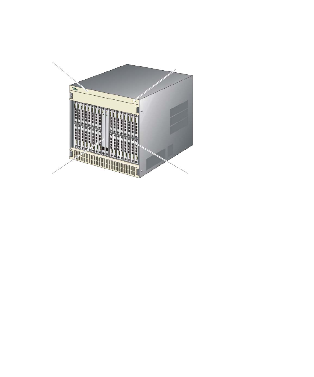
Front view
Figure 1 shows Director 2/140 components accessible from the front of the director. Component
descriptions follow the figure.
1
2
1 Front bezel
2 Power and system error LEDs
Figure 1 Director components—front
CTP card
The Director 2/140 ships with two Control Processor (CTP) cards. The active CTP card initializes
and configures the director after power on, and contains the microprocessor and associated logic
that coordinate director operation. The second CTP card serves as a backup. A CTP card provides
an Initial Machine Load (IML) button on the faceplate. When the button is pressed and held for
three seconds, the director reloads firmware and resets the CTP card without switching off power or
affecting operational fiber-optic links.
Each CTP card also provides a 10/100 megabit per second (Mbps) RJ-45 twisted pair connector
on the faceplate that attaches to an Ethernet Local Area Network (LAN).
Each CTP card provides System Services Processor (SSP) and Embedded Port (EP) subsystems. The
SSP subsystem runs director applications, communicates with director ports, and controls the RS-232
maintenance port and 10/100 Mbps ethernet port. The EP subsystem provides Class F processing,
and manages frame transmission to and from the Serial Crossbar Assembly (SBAR). In addition,
CTP cards provide non-volatile memory for storing firmware director configuration information,
persistent operating parameters, and memory dump files. Director firmware is upgraded
concurrently (without disrupting operation).
4
3
3 UPM cards (32)
4 CTP cards
Overview18

Each card faceplate contains a green light emitting diode (LED) that turns ON if the card is
operational and active, and an amber LED that turns O
backup CTP. The amber LED F
Power/system LED assembly
The bezel at the top front of the director includes an amber system error light-emitting diode (LED)
and a green power LED. These LEDs are actuated and controlled by a Power/system LED assembly
which is accessed from the rear of the director.
The power LED illuminates when the director is powered on and operational. If the LED extinguishes,
a facility power source, alternating current (AC) power cord, or director power distribution failure is
indicated.
The system error LED illuminates when the director detects an event requiring immediate operator
attention, such as a FRU failure. The LED remains illuminated as long as an event is active. The LED
extinguishes when the Clear System Error Light function is selected from the Element Manager
application. The LED blinks if unit beaconing is enabled. An illuminated system error LED (indicating
a failure) takes precedence over unit beaconing.
Power supplies
The Director 2/140 uses redundant, load-sharing power supplies which step down and rectify
facility input power to provide 48-VDC power to director FRUs. The power supplies also provide
over-voltage and over-current protection. Either power supply can be replaced while the switch is
powered on and operational. Each power supply has a separate backplane connection to allow for
different AC power sources.
N if the card fails. The LEDs are OFF on the
LASHES if beaconing is enabled.
The power supplies are input rated at 180 to 264 VAC. The faceplate of each power supply
provides the following status LEDs:
• A green PWR OK LED turns O
• An amber FAULT LED turns O
• An amber TEMP LED turns O
• An amber I LIM LED turns O
Power supply requirements are listed in Appendix B.
UPM card
Each Universal Port Module (UPM) card provides four full-duplex generic ports (G_Ports) that
transmit or receive data at 1.063 or 2.125 gigabits per second (Gb/s). G_Port functionality
depends on the type of cable attachment. UPM cards use Non-Open Fiber Control (NOFC) Class 1
laser transceivers that comply with Section 21 of the Code of Federal Regulations (CFR), Subpart J
as of the date of manufacture.
Depending on device connections, G_Ports work as follows:
• If the G_Port is attached to a Fibre Channel device, the port functions as a fabric port (F_Port).
N if the power supply is operational and receiving AC power.
N if the power supply fails.
N if the power supply shuts down due to an over temperature
condition.
N if the power supply is overloaded and operating at the current
limit (15.6 A).
An F_Port is the interface on a director that connects to a device N_Port.
Director 2/140 installation guide 19
• If the G_Port is attached to another director to form an Interswitch Link (ISL), the port functions as
2
an expansion port (E_Port). A multi-switch fabric is formed through multiple directors and ISLs.
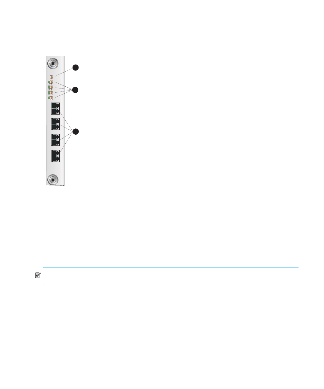
Figure 2 shows the faceplate of an UPM.
UPM
1
2
1 Card LED
2 Por t LEDs
3
3 Port connectors
(G_Ports)
SHR-
Figure 2 UPM card LEDs and connectors
Single-mode or multi-mode fiber-optic cables attach to UPM cards through small form factor
pluggable (SFP) optic transceivers. The fiber-optic transceivers provide duplex connectors, and can
be detached from UPM cards (through a 10-pin interface) for easy replacement. Three fiber-optic
transceiver types are available:
• Short-wave laser—Short-wave laser transceivers provide connections for transferring data over
short distances (2 to 500 meters) through 50-μm (500 meters) or 62.5-μm (200 meters)
multi-mode fiber.
NOTE: HP recommends 50-μm fiber-optic cable for any new installation requiring multi-mode fiber.
• Long-wave laser—Long-wave laser transceivers provide connections for transferring data over
long distances (up to 10 kilometers) through 9-μm single-mode fiber.
• Extended reach long-wave laser—Long-wave laser transceivers that provide connections for
transferring data over extended long distances (up to 35 kilometers) through 9-μm single-mode
fiber.
Overview20
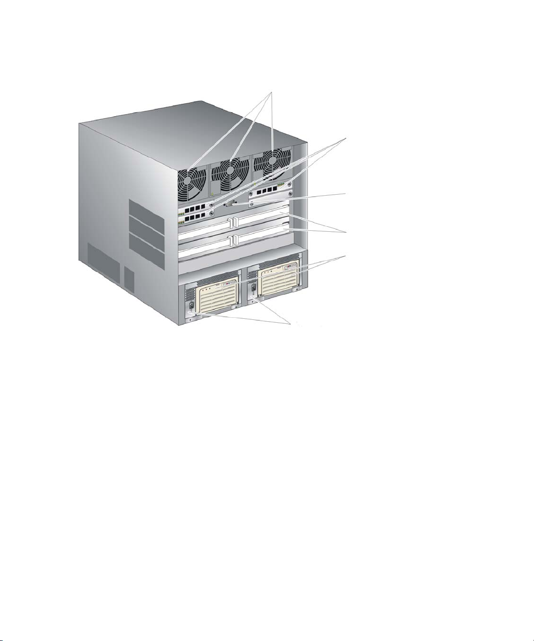
Rear view
Figure 3 shows the components accessible from the rear of the Director 2/140 .
1
2
3
4
5
6
1 Fan modules
2 UPM cards (3)
3 Maintenance port
Figure 3 Director components—rear
Fan modules
Three fan modules, each containing one system fan (three system fans total), provide cooling for
director FRUs, as well as provide redundancy for continued operation if a fan fails.
The fan module can be replaced while the director is powered on and operating, provided the
module is replaced within 10 minutes (after which software powers off the director). An amber LED
for each fan module turns O
SBAR assembly
The director ships with two SBAR assemblies. The active SBAR is responsible for Fibre Channel
frame transmission from any director port to any other director port. Connections are established
without software intervention. The assembly accepts a connection request from a port, determines if
a connection can be established, and establishes the connection if the destination port is available.
The assembly also stores busy, source connection, and error status for each director port.
4 SBAR assemblies
5 AC modules
6 Power supplies
N if one or more fans fail or rotate at insufficient velocity.
Director 2/140 installation guide 21
The backup SBAR takes over operation if the active assembly fails, and provides the ability to
maintain connectivity and data frame transmission without interruption. The transition to the backup
assembly is transparent to attached devices.
Each SBAR assembly consists of a card and steel carriage that mounts flush on the backplane. The
carriage provides protection for the back of the card, distributes cooling airflow, and assists in
aligning the assembly during installation. The rear of the carriage contains a green LED that turns
O
N if the assembly is operational and active, and an amber LED that turns ON if the assembly fails.
The amber LED F
LASHES if FRU beaconing is enabled.
AC module
The AC module is located at the bottom rear of the director. Either AC module can be replaced
while the director is powered on and operational. The module provides:
• Two single-phase, 220 VAC, power connectors.
• An input filter and AC system harness (internal to the FRU) that provides the wiring to connect the
AC power connectors to the power supplies (through the backplane).
Backplane
The backplane provides 48 VDC power distribution and connections for all logic cards. The
backplane is a nonconcurrent FRU. The director must be powered off prior to FRU removal and
replacement.
Tools and test equipment
This section describes tools and test equipment that may be required to test, service, and verify
operation of the director and attached HAFM appliance. These tools are either supplied with the
director or must be supplied by service personnel.
Tools supplied with the director
The following tools are supplied with the director. Use of the tools may be required to perform test,
installation, service, or verification tasks.
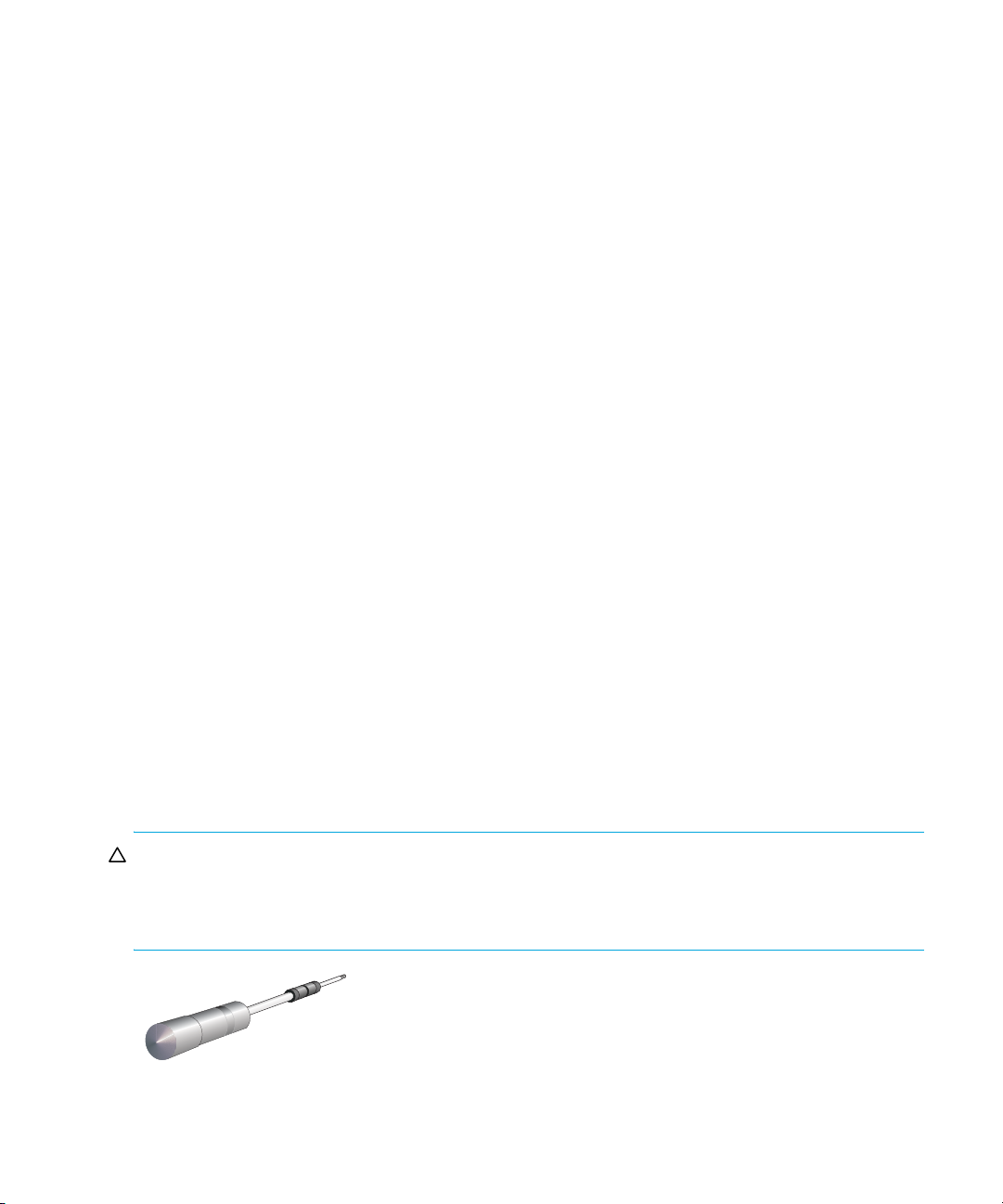
• Torque tool with hexagonal adapter—The torque tool with 5/32” hexagonal adapter (Figure 4),
is required to remove and replace director logic cards.
CAUTION: The torque tool supplied with the Director 2/140 is designed to tighten director logic
cards and is set to release at a torque value of six inch-pounds. Do not use an Allen wrench or
torque tool designed for use with another HP product. Use of the wrong tool may overtighten and
damage logic cards.
Figure 4 Torque tool and hex adapter
Overview22
• Loopback plug—An SFP multi-mode (short-wave laser) or single-mode (long-wave laser)
loopback plug (Figure 5), is required to perform port loopback diagnostic tests. One loopback
plug is shipped with the director, depending on the type of port transceivers installed. Both plugs
are shipped if short-wave laser and long-wave laser transceivers are installed.
Figure 5 Loopback plug
• Fiber-optic protective plug—For safety and port transceiver protection, fiber-optic protective
plugs (Figure 6), must be inserted in all director ports without fiber-optic cables attached. The
director is shipped with protective plugs installed in all ports.
Figure 6 Fiber-Optic protective plug
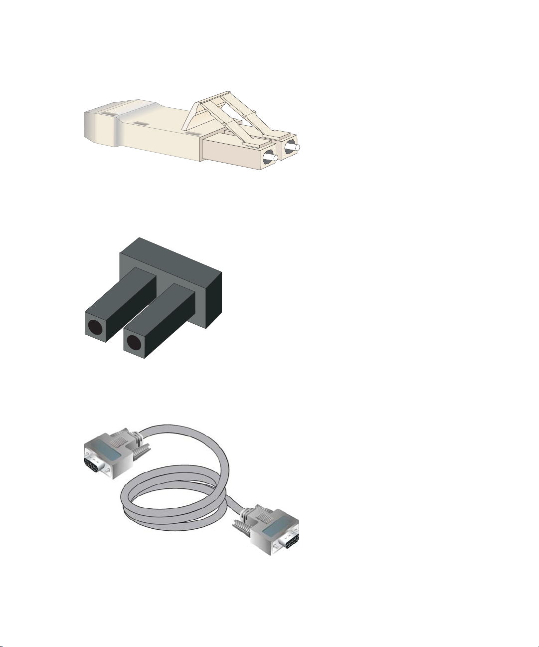
• Null modem cable—An asynchronous RS-232 null modem cable (Figure 7) is required to
configure director network addresses and acquire event log information through the
maintenance port. The cable has nine conductors and DB-9 male and female connectors.
Figure 7 Null modem cable
Director 2/140 installation guide 23

Tools supplied by service personnel
The following tools are expected to be supplied by service personnel performing director installation
or maintenance actions. Use of the tools may be required to perform one or more test, service, or
verification tasks.
• Scissors or pocket knife—A sharp cutting edge (scissors or knife blade) may be required to cut
the protective strapping when unpacking replacement FRUs.
• Standard flat-tip and cross-tip (Phillips) screwdrivers—Screwdrivers are required to remove,
replace, adjust or tighten various FRUs, chassis, or cabinet components.
• T10 Torx
tighten various chassis or cabinet components.
• Electrostatic discharge (ESD) grounding cable with attached wrist strap—Use of the ESD wrist
strap is required when working in and around the director card cage.
• Maintenance terminal (desktop or notebook PC)—The PC is required to configure director
network addresses and acquire event log information through the maintenance port. The PC
must have:
• The Microsoft
• RS-232 serial communication software (such as ProComm Plus™ or HyperTerminal™)
• Fiber-optic cleaning kit—The kit contains tools and instructions to clean fiber-optic cable,
connectors, loopback plugs, and protective plugs.
® tool—The tool is required to rack-mount the director or to remove, replace, adjust, or
® Windows 98®, Windows
Windows ME
® operating system installed.
installed. HyperTerminal is provided with Windows operating systems.
2000®, Windows 2003®, Windows XP®, or
Optional kits
Contact your HP authorized service provider to purchase the following optional director kits. See
Table 2 for descriptions of Director 2/140 optional kits.
Table 2 Director optional kits
Supporting kit Description
HP Full Volatility License.
Part Number: A7498A
HP Open Trunking License.
Part Number: A7506A
HP SANtegrity Binding License.
Part Number: 317073-B21
300m Optical Transceiver Kit,
Part Number: 300834-B21
10km Long Distance Optical
Transceiver Kit,
Part Number: 300835-B21
Overview24
Provides a license to use Full Volatility feature.
Provides a license to use Open Trunking feature.
Provides a license to use SANtegrity Binding feature.
Provides short-wave optical transceiver for the
director.
Provides 10km long-wave optical transceiver for the
director.
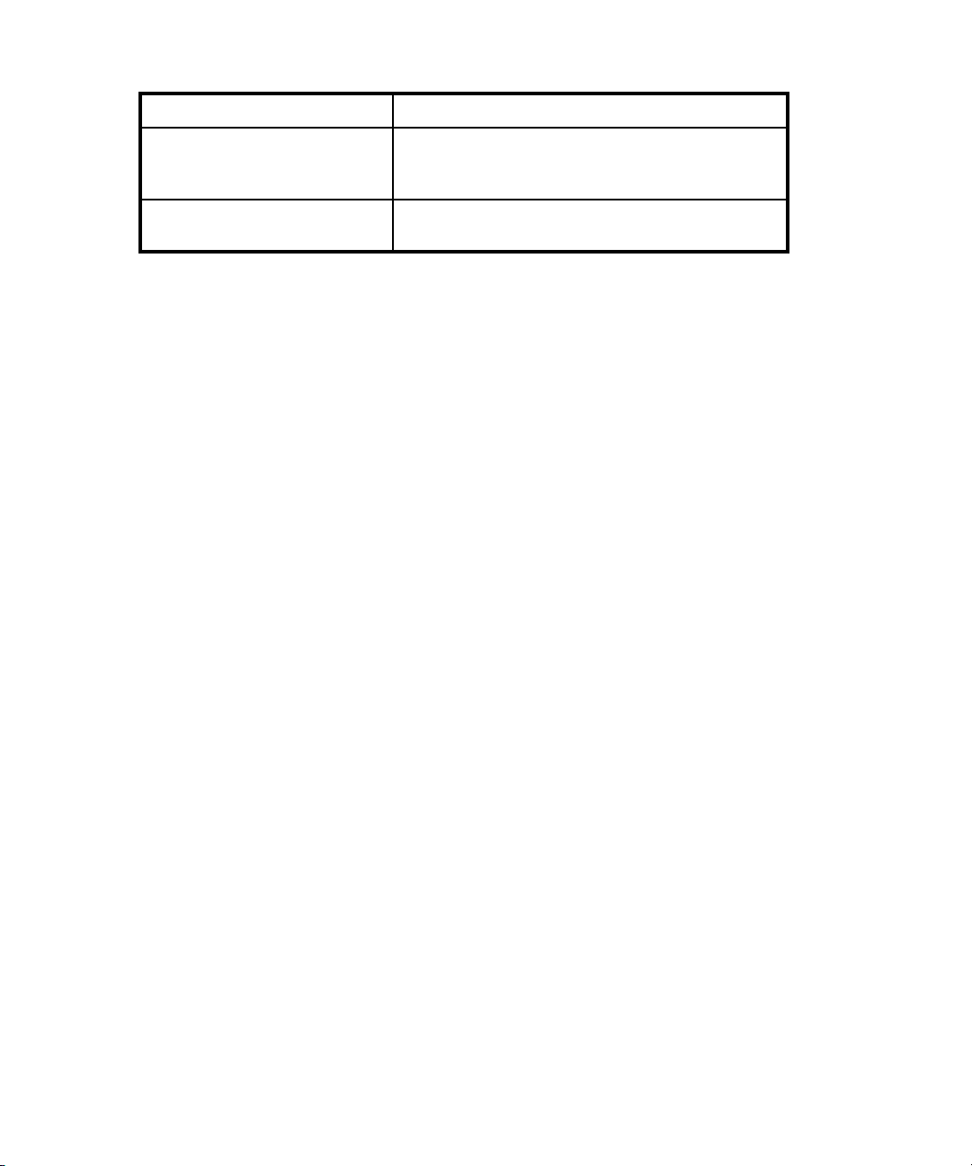
Table 2 Director optional kits (continued)
Supporting kit Description
35km Extended Reach Optical
Transceiver Kit,
Part Number: 300836-B21
2Gb UPM Port Module Kit,
Part Number: 316094-B21
Provides 35km long-wave optical transceiver for the
director.
Provides 4 additional short-wave ports for the
Director 2/140.
Director 2/140 installation guide 25

Overview26

2 Installing and configuring the director
This chapter describes tasks to install, configure, and verify operation of the director. This chapter
describes the following:
• Installation options, page 27
• Review installation requirements, page 27
• Unpack and inspect the director, page 29
• Configure director network information, page 39
• LAN-connect the director, page 44
• HAFM appliance, page 45
• Frequently used HAFM settings, page 50
• Connecting cables to the Fibre Channel ports, page 87
• Connecting the director to a fabric, page 72
• Unpacking, inspecting, and installing the Ethernet hub (optional), page 73
• Using HAFM from a remote location, page 73
Installation options
The director is installed in one of the following configurations:
• Table or desk top—One or more directors and an optional HAFM appliance are delivered and
installed at the customer facility on a desk or table top. Ethernet cabling distance and local area
network (LAN) addressing issues must be considered.
• Customer-supplied equipment rack—One or more directors and an optional HAFM appliance
are delivered to the customer facility for installation in an HP or customer-supplied equipment
rack. Rack-mount hardware is provided in the shipping container. Ethernet cabling, distance,
and LAN addressing issues must be considered.
Review installation requirements
The director is delivered stand-alone and ready to be mounted in an HP 9000, HP 10000, HP
11000, HP system/e, or industry-standard 19-in rack. Ethernet cabling, distance, and LAN
addressing issues must be considered.
Review the following checklist before installing the switch:
• Prepare a site plan. Consult the HP StorageWorks SAN high availability planning guide.
• Manage the director using one of the following methods:
• A browser-capable PC and LAN segment connectivity to the HAFM appliance to support
director management through HAFM and the Element Manager.
• A browser-capable PC and Internet connectivity to support director management through the
EWS interface.
• Verify that required technical personnel are available and scheduled for the installation.
Director 2/140 installation guide 27

• Obtain the required fiber-optic cables (multi-mode or single-mode). Verify cable length and
required connectors.
• Obtain an HP 19-inch equipment rack.
• Verify that the front panel air temperature does not exceed 40 °C (104 °F) during operation.
NOTE: Height measurements are sometimes described in rail units (Us). One U is 1.75 in.
• Verify that there is space in the rack. The director is 12U (20 in) high.
• Verify that the rack is stable.
• If applicable, obtain the necessary remote workstations or Simple Network Management
Protocol (SNMP) workstations. Workstations are customer-supplied and connected through a
corporate or dedicated LAN.
• Verify that all other equipment installed in the rack is connected to a reliable ground connection;
do not rely on connections to a branch circuit, such as a power strip.
• HP recommends securing the rack mechanically to prevent it from tipping over during a natural
disaster, such as an earthquake.
Items required for installation
Locate the following items before beginning the installation procedure:
• Lift device (recommended).
• Director 2/140.
• An HP 9000, HP 10000, HP 11000, HP system/e, or industry-standard 19-in rack, or any rack
with the following specifications:
• A minimum depth of 24.5 in.
•19 in wide.
• A minimum opening size of 13U available (12U for the director and 1U for space
recommended for routing of cables).
• Two power outlets or different branches (for redundancy).
• Torque driver with cross-tip bit (for setting 22 in/lb. of torque).
• Fiber-optic protective plug—For safety and port transceiver protection, fiber-optic protective plugs
must be inserted in all director ports without fiber-optic cables attached. The director is shipped
with protective plugs installed in all ports.
• Null modem cable—An asynchronous RS-232 null modem cable is required to configure director
network addresses and obtain event log information through the maintenance port. The cable
has nine conductors and two DB-9 female connectors. A null modem cable specially designed
for this application is supplied with the Director 2/140.
• Standard flat-tip and cross-tip Phillips screwdrivers—required to remove, replace, adjust or
tighten various FRUs, chassis, or rack components.
• Electrostatic discharge (ESD) grounding cable with attached wrist strap—required when working
in and around the director card cage.
.
Installing and configuring the director28

• Maintenance terminal (desktop or notebook computer)—required to configure director network
addresses and acquire event log information through the maintenance port. Computer
requirements include:
• Microsoft Windows 98, Windows Millennium Edition, Windows NT 4.0, Windows 2000, or
Windows XP operating system installed.
• RS-232 serial communication software (for example, ProComm Plus or HyperTerminal).
NOTE: The HAFM appliance may be used for the maintenance terminal function. The
HyperTerminal application is included with the Windows 2000 operating system provided with the
HAFM appliance.
Select an operating location
Install the director in a secure or limited-access area to ensure that cable connections are not
compromised. Also, make sure to install the director in an area with the necessary ventilation and
power requirements.
Cooling and power requirements
Two fan modules, each containing three fans (six fans total), provide cooling and redundancy fans
for the director. The air intake for the director must satisfy an operating environment temperature
requirement of 40°F to 104°F (4°C to 40°C).
Director power requirements:
• Input voltage: 180 to 264 VAC
• Input frequency: 47/63 Hz
CAUTION: Do not block Director 2/140 air vents. The switch uses ambient air for cooling
Unpack, inspect, and install the director
The following paragraphs provide instructions to unpack and inspect one or more Director 2/140s,
and install the directors on a desktop or in a rack-mount configuration.
Unpack and inspect the director
Unpack and inspect the director(s) as follows:
1. Inspect the shipping containers for damage caused during transit. If a container is damaged,
ensure a representative from the freight carrier is present when the container is opened.
2. Unpack the shipping containers and inspect each item for damage. Ensure the items match the
items listed on the bill of materials (BOM).
3. If any items are damaged or missing, customers should call the toll-free telephone number
printed on the service label attached to the back of the director.
Director 2/140 installation guide 29
Install the director on a desktop
To install the director on a desktop:
1. Position the director on a table or desktop as directed by the customer.
CAUTION: Four person lift—the director weighs approximately 167 lbs. Do not attempt to lift or
carry the director with fewer than four people. Failure to observe this CAUTION may result in injury
to personnel or damage to the director.
2. Verify all field-replaceable units (FRUs), including logic cards, fans, and power supplies are
installed as ordered.
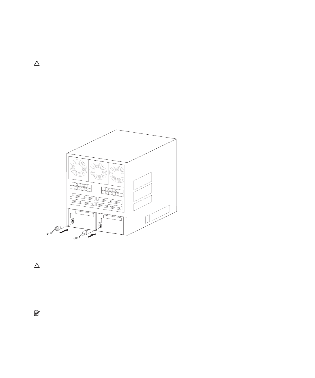
3. Connect the U.S. or country-specific (optional) AC power cords to the right (PS0) and left (PS1)
receptacles at the rear of the director (Figure 8).
Figure 8 AC power connections (director)
WARNING! An HP-supplied power cord is provided for each director power supply. To prevent
electric shock when connecting the director to primary facility power, use only the supplied power
cord(s), and ensure the facility power receptacle is the correct type, supplies the required voltage,
and is properly grounded.
NOTE: The director does not have a power switch. Therefore the director powers on when its
power cords are connected to facility power.
Installing and configuring the director30
 Loading...