

Page 1

HP StorageWorks
Director blade i
nstallation
instructions
Overview
Read these installation instructions if you have purchased one of the
optional Director blades listed in Table 1. Install the Director blades in
compatible models only.
NOTE:
This document refers to blades by their short names.
Table 1 Director blades
© Copyright 2008 Hewlett-Packard Development Company, L.P.
First edition: March 2008
The information in thi s document is subject to change without
notice.
Printed in the U.S.
www.hp.com
Model
HP
StorageWorks
SAN Director
16 Po r t , 4G b
FC blade
HP
StorageWorks
SAN Director
32 Port, 4Gb
FC blade
HP
StorageW
SAN Direc
48 Port, 4
FC blade
HP
StorageWorks
SAN Director
16 Po rt 8 Gb
FC blade
HP
StorageWorks
SAN Director
32 Port 8Gb
FC blade
HP
StorageWorks
SAN Director
48 Port 8Gb
FC blade
orks
tor
Gb
Short name
(imprinted on
blade)
FC4-16 A7990A
FC4-32 A7991A
FC4-48 AG561A
FC8-16
FC8-32
FC8-48 AK860A
Part number
AK858A
AK859A
Compatible
Director
models
2/128 SAN
Director or
4/256 SAN
Director
4/256 SAN
Director
4/256 SAN
Director
4/256 SAN
Director or
nl
DC SAN
Backbon
Directo
DC SAN
Backbone
Director
DC SAN
Backbone
Director
e
r
K858-96001*
*A
Page 1
HP
StorageWorks
SAN Director 6
Por t 10Gb FC
blade
HP
StorageWorks
B-Series iSCSI
Director blade
HP
StorageWorks
B-Series
Multi-protocol
(MP) Router
blade
FC10-6
FC4-16IP AG671A
FR4-18i AG461A
AK861A
4/256
Dire
nl
DC SAN
Backbone
Director
4/256 SAN
Director
4/256 SAN
Director or
nl
DC SAN
Backbone
Director
SAN
ctor or
Page 2
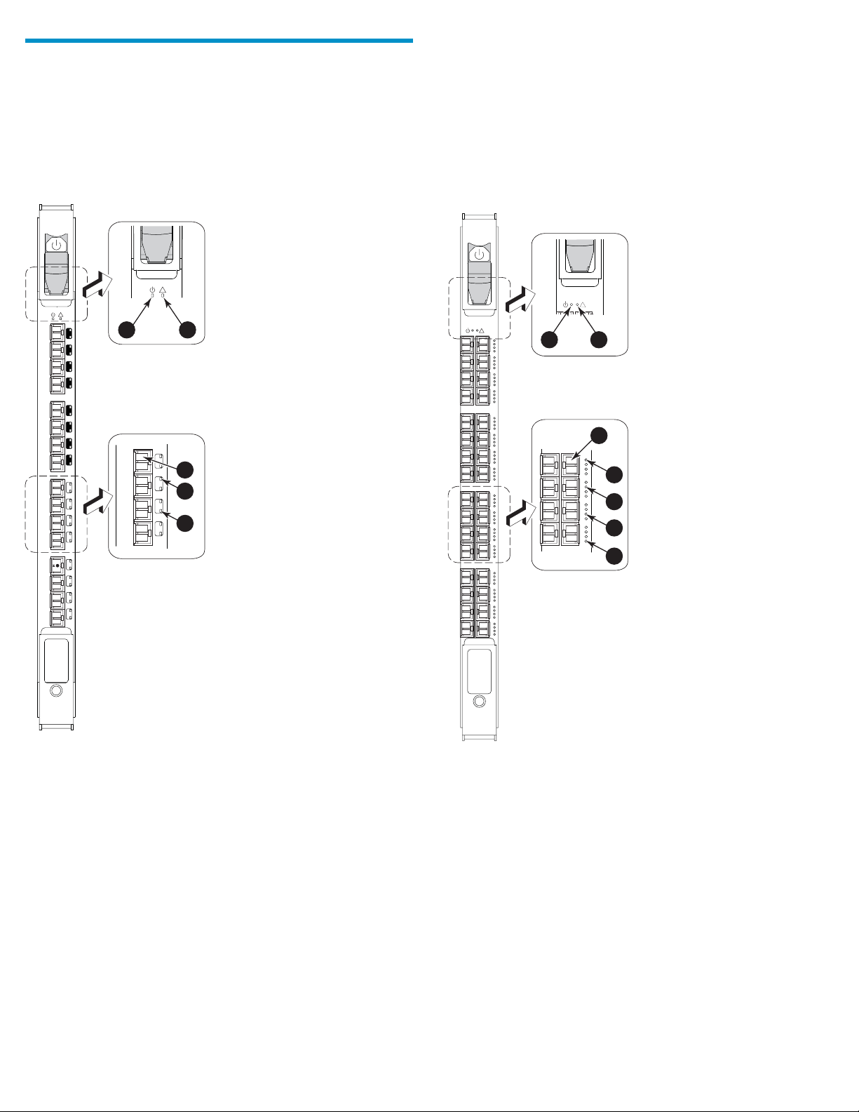
Identifying blade components
The following sections illustrate Director blade compon ents.
FC4-16 components
Figure 1 identifies FC4-16 components. Ports are numbered 0 through
15,frombottomtotop.
!
!
15
14
13
12
11
10
9
8
7
6
5
4
3
2
1
0
1
2
7
3
6
4
5
5
4
FC4-32 components
Figure 2 identifies FC 4-32 components.
!
!
1
2
3
4
5
6
7
FC4
16
Figure1FC4-16blade
1. Power LED
2. Status LED
3. FC port
25363a
4. Port speed LED
5. Por t status LED
FC4
32
Figure2FC4-32blade
1. Power LED
2. Status LED
3. FC port
4. Port speed LED (left port)
25364a
5. Port status LED ( left port)
speed LED (right port)
6. Port
7. Port status LED (righ t port)
Page 2
Page 3
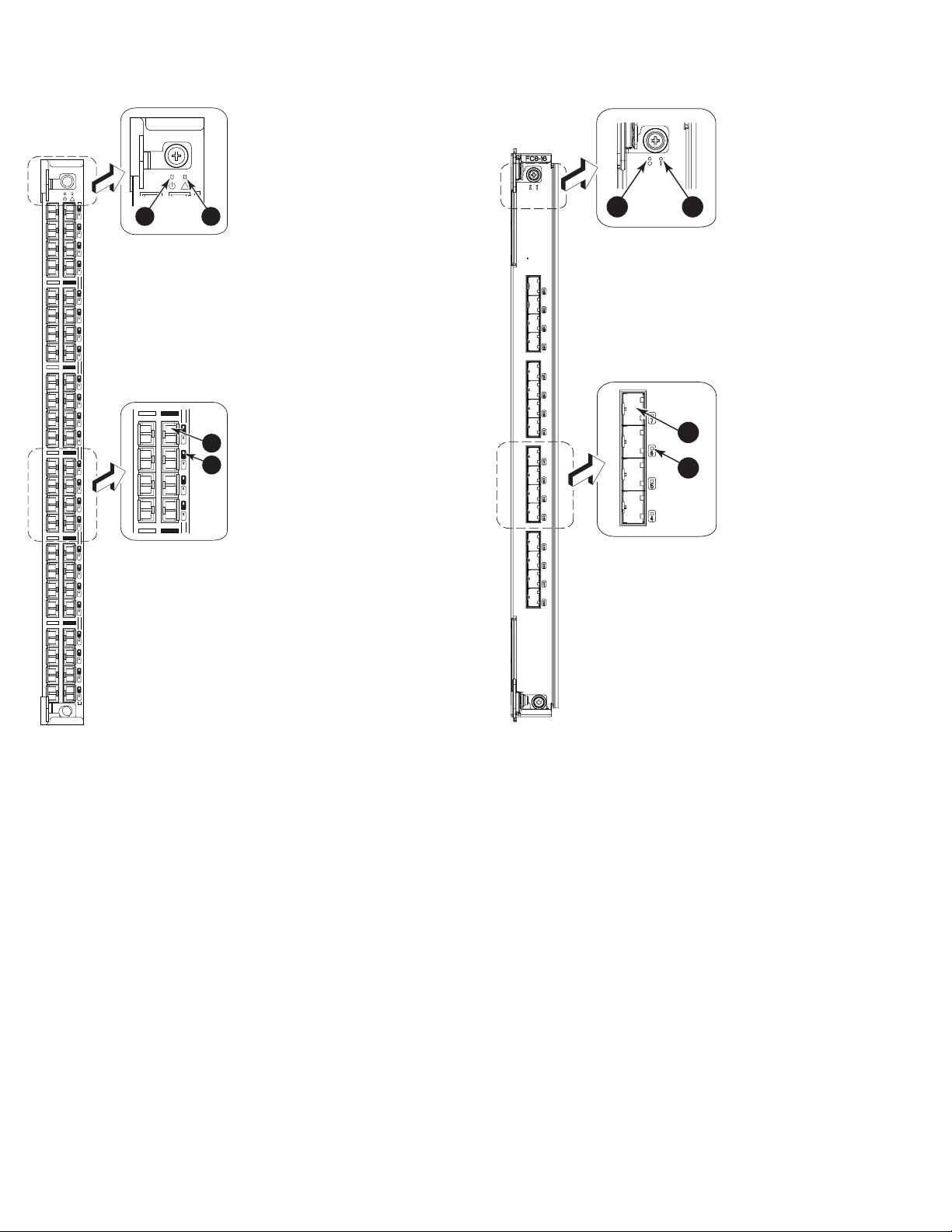
FC4-48 components
FC8-16 componen
ts
Figure 3 identifi
!
es FC4-48 components.
47
23
46
22
45
21
44
20
43
19
42
18
41
17
40
16
39
15
38
14
37
13
36
12
35
11
34
10
33
9
32
8
31
7
30
6
29
5
28
4
27
3
26
2
25
1
24
0
1
!
35
11
34
10
33
9
32
8
Figure3FC4-48blade
1. Power LED
2. Status LED
2
3
4
25365a
3. FC port
4. Port status LED
Figure 4 identifies FC8-16 components.
1
2
3
4
25362a
Figure 4
1. Power LED
2. Statu
FC8-16 blade
sLED
3. FC port
4. Port stat us LED
Page 3
Page 4

FC8-32 componen
ts
FC8-48 components
Figure 5 identifies FC8-32 components.
1
Figure 5 FC8-32 blade
1. Power LED
2. Status LED
3. FC port
4. Port status LED
2
3
4
25367a
Figure 6 identifi
es FC8-48 components.
!
47
23
46
22
45
21
44
20
43
19
42
18
41
17
40
16
39
15
38
14
37
13
36
12
35
11
34
10
33
9
32
8
31
7
30
6
29
5
28
4
27
3
26
2
25
1
24
0
1
Figure6FC8-48blade
1. Power LED
2. Status LED
35
11
34
10
33
9
32
8
!
47
2
3
4
25366a
3. FC port
4. Port stat us LED
Page 4
Page 5

FC10-6 componen
ts
FC4-16IP components
Figure 7 identifies FC10-6 components.
1
2
3
4
Figure 8 identifi
!
7
6
5
4
GE
3
2
1
0
7
6
5
4
FC
3
2
1
0
es FC4-16IP components.
!
1
FC
2
7
3
6
4
5
4
Figure 7 FC10-6 blade
1. Power LED
2. Status LED
25368a
3. FC port
4. Port s
tatus LED
FC4
16IP
Figure 8 FC4-16IP blade
1. Power LED
2. Status LED
25358a
3. FC port
4. Port stat us LED
Page 5
Page 6

FR4-18i components
Figure 9 identifi
!
15
14
13
12
11
10
9
8
7
6
5
4
3
2
1
0
GE0
GE1
es FR4-18i components.
!
1
2
7
3
6
4
5
4
Verifying installation requirements
The installation takes less t han 10 minutes. Obtain the following items:
• Replacement Director blade
• Replacement filler panel for each empty slot (ships with the Director
blade)
• Electrostatic discharge (ESD) grounding strap
• Workstation computer
• Phillips screwdriver
• Small form-factor pluggable (SFP) transceivers, as needed
• Extended form-factor pluggable (XFP) transceivers, as needed (for
the FC10-6 Director b lad e only)
• Optical cables, as needed
IMPORTANT:
Order SFP transceivers separately. The HP DC SAN Backbone
Director 8Gb port blades support HP transceivers labeled
“B-Series FC SFP" only. Check h
ttp://www.hp.com for more
information on supported transceivers.
Removing the filler panel
Remove the filler panel, if installed. There are three filler panel types
(Figure 10).
FR4
18 i
Figure 9 FR4-18i blade
1. Power LED
2. Status LED
25359a
3. FC port
4. Port s
tatus LED
IMPORTA
NT:
Remove a filler panel only when installing or replacing a new
Director blade. Any slot that is not occupied by a Director blade
requires a filler panel to ensure correct cooling of the chassis
and protection from dust.
Page 6
Page 7

!
Determining the ejector type
!
6
5
4
3
2
1
200-240 VA
!
56
-0
0
005
9
0
-0
1
R
e
v
A
!
!
5
1
4
1
I O I O I RS - 232
3
1
I O I O I RS - 232
2
1
1
1
0
1
s
k
/
b
in
L
M
0
0
1
/
0
1
9
P
s
k
/
C
n
e
b
Li
iv
M
t
c
0
A
0
/1
8
0
1
P
C
e
tiv
c
A
7
6
5
4
3
2
1
0
CP4
CP4
FC4
16
200-240 VA
0-60 Hz
C 12A 5
10
9
8
7
56
-
0
0
0059
0
-01
R
e
v
A
!
5
1
14
3
1
2
1
1
1
10
9
8
7
6
5
4
3
2
1
0
FC4
16
C 12A 50-60 Hz
4
Y
L
P
P
U
S
R
E
W
O
P
3
Y
L
P
P
U
S
R
E
W
O
P
!
!
2
Y
L
P
P
U
S
R
E
W
O
P
!
!
1
1
LY
LY
P
P
P
P
U
U
S
S
R
R
E
E
W
W
O
O
P
P
2
1
3
Installation procedures differ depending on the ejector mechanism on
the Director blade. Read the following sections to identify your blade’s
ejector type.
Director blade
swithejectorsandslider
switches
The following Director blades use both ejectors and slider switches:
• FC4-16
• FC4-32
• FC10-6
• FC4-16IP
• FR4-18i
Director blades with ejectors
Figure 10
Removing three different filler panel types
1. Filler panel with handle
rpanelwithhandle
2. Fille
captive
screws (2)
8
5. Ejectors (2)
6. Fille
captive
6
7
5
r panel with pull tabs
screws (2)
3. Handle 7. Pull tabs (2)
4. Filler panel with ejectors 8. Filler panel with pull tabs
To remove a filler panel with a handle:
1. Unscrew the two captive screws securing the filler panel.
2. Grasp the handle and remove the filler panel.
To remove a filler panel with ejectors:
1. Push in the yellow tab on each ejector.
2. Open both ejectors and remove the filler panel from the chassis.
To remove a filler panel with pull tabs:
1. Unscrew the top and bottom captive screws on the filler panel.
2. Graspthetopandbottompulltabsandremovethefiller panel.
4
25043b
The followi
ng Director blades use ejectors only:
• FC8-16
• FC8-32
• FC8-48
• FC4-48
Installing the Director blade
To install the Director blade:
CAUTION
Wear a grounded ESD strap when handling the Director blade.
The Director chassis provides a grounding connection above the
power connectors.
1. Identi
"Deter
2. Locate an appropriate slot. Slots are numbered from left to right
when f
For the 4/256 SAN Director Switch: Install Director blades in slots
1through4and7through10.
FortheDCSANBackboneDirectorSwitch: Install Director blades
in slots 1 through 4 and 9 through 12.
3. Ori
(aw
bla
:
fy the ejector type for your blade, as described in
mining the ejector type".
acing the port side of the chassis.
ent the Director blade so that the blade’s ports face outward
ay from the slot), and the flat (non-component) side of the
de is on the left.
Page 7
Page 8

4. Go to Step 5 if you
installing uses
ForDirectorbla
ejectors only. See "Determining the ejec tor type".
des with both ejectors and slider switches:
a. Open the ejecto
side of the Director blade inside the upper and lower rail
guides in the slot, and slide the Director blade into the slot,
with slight pr
2
1
Figure 11 Removing and repl acing a Director blade
with e jectors and slider switches (FC4-16 shown)
have determined that the Director blade you are
rs to approximately 45 degrees, align the flat
essure to the left (Figure 11).
1
3
200-240 VA
1
R
e
v
A
4
5
6
-
0
0
0
05
9
0
-0
!
5
1
4
1
3
1
2
1
1
1
0
1
9
8
7
6
5
4
3
2
1
0
FC4
16
C 12A 50-60 Hz
!
!
8
7
6
5
5
6
-
0
0
0
0
5
9
0
-0
1
Re
v
A
!
5
1
4
1
3
1
!
2
!
I O I O I RS - 232
k
Lin
10/100 Mb/s
Active CP
CP4
1
1
1
0
1
I O I O I RS - 232
9
8
7
6
k
Lin
5
10/100 Mb/s
4
Active CP
3
2
1
0
FC4
32
FC4
16
CP4
C 12A 50-60 Hz
0 VA
-24
200
!
!
10
9
FC4
32
PLY 4
ER SUP
W
PO
!
!
WER SUPPLY 3
PO
!
!
2
ER SUPPLY
W
PO
!
!
WER SUPPLY 1
WER SUPPLY 1
PO
PO
2
5
6
-
0
0
0
0
5
9
0
-0
1
R
e
v
A
!
5
1
4
1
3
1
2
1
1
1
0
1
9
8
7
6
5
4
3
2
1
0
FC4
16
4
3
25217a
1
!
!
8
7
6
5
56
-
0
0
0
0
59
0
-01
Rev A
4
3
2
1
-0
00
0
590
-
0
1
R
e
v
A
!
5
1
4
1
13
2
1
1
1
0
1
9
8
7
6
5
4
3
2
1
0
FC
16
0 VAC
-24
200
!
5
1
4
1
3
1
!
56
4
12A
2
1
!
1
1
0
1
I O I O I RS - 232
9
8
I O I O I RS - 232
7
6
s
k
Lin
5
100 Mb/
10/
s
k
Lin
4
Active CP
100 Mb/
10/
Active CP
3
2
1
0
4
FC
16
P4
C
P4
C
50-60
AC 12A
0 V
200-24
50-60 Hz
!
!
0
1
9
4
FC
32
FC4
32
Hz
Y 4
L
PP
ER SU
W
PO
!
!
Y 3
PPL
SU
ER
OW
P
!
!
LY 2
SUPP
ER
OW
P
!
!
Y 1
Y 1
PL
PL
POWER SUP
POWER SUP
2
3
!
7
4
3
2
6
4
2
2
5
4
1
2
4
4
0
2
3
4
9
1
2
4
8
1
1
4
7
1
0
4
6
1
9
3
5
1
8
3
4
1
7
3
3
1
6
3
2
1
5
3
1
1
4
3
0
1
3
3
9
2
3
8
1
3
4
7
0
3
6
9
2
5
8
2
4
7
2
3
6
2
2
5
2
1
4
2
0
25223a
Figure 12 Removing and replacing a Director blade
with ejectors only (FC4-48 shown)
1. 4/256 SAN Director
chassis
2. FC4-48
3. Upper ejector
4. Lower ejector
d. Close the ejectors.
6. Verify that the power LED on the Director blade is displaying a
steady green light and that the Director blade is seated firmly.
7. Install the SFP or XFP (FC10-6 only) transceivers and cables.
1. 4/25
chassi
2. FC4-16
b. Close
6SANDirector
s
3. On/Off slider switch
4. Ejector
the ejectors by pushing the handles toward the center
of the blade until the ejectors lock. The levering action of the
handles seats the blade in the slot.
c. Tighten the thumb screw inside each handle using the Phillips
screwdriver.
d. Turn the blade on by sliding the slider switch in the top ejector
up, covering the thumb screw.
e. Go to Step 6.
5. For Director blades with ejectors:
a. Open the ejectors.
b. Align the flat side of the Director blade inside the upper and
lower rail guides in the slot.
c. SlidetheDirectorbladeintotheslotuntilitisfirmly seated
(Figure 1 2).
For mo
This do
re configuration information
cument provides initial setup and configuration procedures only.
See the following documents for more comprehensive configuration
dures (including mixed blade configurations):
proce
• HP St
orageWorks SAN Director hardware reference guide or HP
StorageWorks DC SAN Backbone Director hardware reference
guide
• HP StorageWorks Fabric OS 6.x administrator guide
• iSCSI Gateway Service administrator guide
the latest documentation and firmware releases, go to
For
ttp://www.hp.com/go/san.
h
Page 8
 Loading...