

Page 1

HP StorageWorks
9000–series Virtual Library System User Guide
This document describes the HP StorageWorks VLS9000 systems to facilitate their installation, operation, and
maintenance. This document is intended for system administrators who are experienced with setting up and
managing large storage systems.
*AG306-96027*
Part number: AG306-96027
Eighth edition: March 2010
Page 2

Legal and notice information
© Copyright 2007, 2010 Hewlett-Packard Development Company, L.P.
The information contained herein is subject to change without notice. The only warranties for HP products and services are set
forth in the express warranty statements accompanying such products and services. Nothing herein should be construed as
constituting an additional warranty. HP shall not be liable for technical or editorial errors or omissions contained herein.
WARRANTY STATEMENT: To obtain a copy of the warranty for this product, see the warranty information website:
http://www.hp.com/go/storagewarranty
Page 3

Contents
1 Introduction ..................................................................................... 17
VLS9000-series Components ...................................................................................................... 17
2 Hardware Installation ....................................................................... 21
Preparing for the Installation ....................................................................................................... 21
Tools for Installation ............................................................................................................ 21
Taking ESD Precautions ....................................................................................................... 21
Grounding Methods to Prevent Electrostatic Discharge ............................................................. 21
Unpacking ............................................................................................................................... 22
Removing the Packing Materials .................................................................................................. 22
Rack Planning Resources ............................................................................................................ 22
Rack Requirements .................................................................................................................... 23
Rack Warnings ......................................................................................................................... 23
Identifying the VLS Shipping Carton Contents ............................................................................... 23
VLS9000 7.5 TB and 10 TB Systems Shipping Carton ............................................................. 24
VLS9000 Single Expansion Disk Array Enclosure Shipping Carton ............................................ 25
VLS9000 Node Shipping Carton ......................................................................................... 25
VLS9000 Array Shipping Carton .......................................................................................... 26
VLS9000 20-port Connectivity Kit Shipping Carton ................................................................ 27
VLS9000 32-port Connectivity Kit Shipping Carton ................................................................. 28
VLS9000 Interswitch Link Kit Shipping Carton ........................................................................ 29
VLS9000-series Hardware Installation Overview ........................................................................... 29
Installing the VLS9000 7.5 TB and 10 TB Systems ......................................................................... 31
Installing PDUs ......................................................................................................................... 32
Installing the VLS9000 Node into a Rack ..................................................................................... 34
Installing Fibre Channel Switches 4/10q onto Racking Shelf ........................................................... 42
Attaching Rails to Fibre Channel Switches 4/16q ......................................................................... 43
Racking Fibre Channel Switches 4/10q or 4/16q ........................................................................ 44
Installing the 1 Gb Ethernet Switch 2810–24G into a Rack ............................................................ 46
Installing Cage Nuts and Rail Flanges in the Rack .................................................................. 47
Attaching Rails to the Ethernet Switch 2810-24G .................................................................... 47
Installing Ethernet Switch 2810-24G in Rack .......................................................................... 48
Installing the 100 Mb Ethernet Switch 2510–24 into a Rack ........................................................... 49
Installing the Disk Array Enclosures into a Rack ............................................................................. 50
Rack Mounting Requirements ............................................................................................... 50
Mounting a Disk Array Enclosure into a Rack ......................................................................... 52
Installing Power Cables ....................................................................................................... 57
Installing VLS9000 Cables ......................................................................................................... 58
Cabling the Nodes ............................................................................................................. 58
Cabling Disk Array Enclosures ............................................................................................. 60
Cabling Ethernet Switch 2510–24 ........................................................................................ 61
Cabling Ethernet Switch 2810–24G ..................................................................................... 62
Cabling Fibre Channel Switch 4/10q ................................................................................... 63
Cabling Fibre Channel Switch 4/16q ................................................................................... 64
Management Ports and External Connections ......................................................................... 66
HP StorageWorks 3
Page 4

Installing VLS9000–series Interswitch Link Kit ................................................................................ 66
Reconfiguring Fibre Channel Switches 4/16q ........................................................................ 67
Reconfiguring Ethernet Switches ........................................................................................... 68
Installing XPAK Transponders ............................................................................................... 68
Applying Labels ................................................................................................................. 70
Installing Interswitch Fibre Channel Cables ............................................................................ 70
Installing Interswitch Ethernet Cables ..................................................................................... 71
3 Multi-node Setup ............................................................................. 73
Configuring Primary Node 0 ...................................................................................................... 73
Configuring the Secondary Nodes 1 through 7 ............................................................................ 73
4 Storage Configuration ...................................................................... 75
Managing VLS9000–series Capacity .......................................................................................... 75
Adding a VLS9000 Capacity Kit .......................................................................................... 75
Removing a VLS9000 Capacity Kit ....................................................................................... 76
Configuring the Storage Pool Policy ...................................................................................... 77
Viewing the Storage Pool .............................................................................................. 77
Rebuilding all Storage Pools .......................................................................................... 77
Rebuilding a Storage Pool ............................................................................................. 78
Installing Additional Licenses ...................................................................................................... 79
5 Automigration/Replication ................................................................ 81
Understanding Automigration Concepts ....................................................................................... 82
Echo Copy Concepts .......................................................................................................... 82
Smart Copy Concepts ......................................................................................................... 83
Replication Concepts .......................................................................................................... 83
Tape Initialization ............................................................................................................... 84
Connecting a Destination Library ................................................................................................ 85
Supported Destination Library Configurations ......................................................................... 85
Connecting a Destination Library to a VLS9000 ..................................................................... 85
Managing and Unmanaging a Destination Library ........................................................................ 85
Managing a SAN Library .................................................................................................... 86
Managing a LAN/WAN Replication Library .......................................................................... 86
Unmanaging a SAN or LAN/WAN Library ........................................................................... 87
Echo Copy Pool Operations ....................................................................................................... 88
Creating an Echo Copy Pool ................................................................................................ 89
Creating Virtual Tapes ........................................................................................................ 94
Restoring from a SAN Physical Cartridge ............................................................................... 94
Restoring from a LAN/WAN Virtual Cartridge ....................................................................... 95
Loading Blank Media into an Echo Copy Pool ........................................................................ 95
Loading Media into an Echo Copy Pool for Overwrite ............................................................. 96
Restarting a Broken Mirror ................................................................................................... 96
Viewing Cartridges in Automigration Source Libraries ............................................................. 97
Viewing Automigration Cartridges in the Firesafe .................................................................... 97
Smart Copy Pool Operations ...................................................................................................... 97
Editing SMI-S Settings ......................................................................................................... 97
Creating a Smart Copy Pool ................................................................................................ 98
Changing the Number of Drives in a Smart Copy Pool ............................................................ 99
Loading Blank Media into a Smart Copy Pool ........................................................................ 99
Loading Media into a Smart Copy Pool for Overwrite ............................................................. 99
Editing Copy Pools .................................................................................................................. 100
Moving a Copy Pool ......................................................................................................... 100
4
Page 5

Changing the Slot Mapping for a SAN Library .................................................................... 100
Changing the Slot Mapping for a LAN/WAN Library ........................................................... 102
Editing the SAN or LAN/WAN Policy ................................................................................. 103
Editing the SAN or LAN/WAN Availability Windows ........................................................... 103
Deleting a Copy Pool ........................................................................................................ 103
SAN Destination Library Operations .......................................................................................... 103
Monitoring Destination Library Status .................................................................................. 104
Cartridge Status and Slot Details ................................................................................. 104
Advanced Search for Slots .......................................................................................... 107
Mailslot Details ......................................................................................................... 107
Copy Pool Details ...................................................................................................... 107
Import/Export Pool Details .......................................................................................... 107
Tape Drive Details ...................................................................................................... 108
Forcing a Replication Job .................................................................................................. 108
Placing a Library Offline or Online ..................................................................................... 108
Moving Media from One Slot to Another ............................................................................. 109
Ejecting Media from a Slot into an Empty Mailslot ................................................................ 109
Ejecting Media from a Drive into an Empty Mailslot .............................................................. 110
Restarting Automigration/Replication Services ...................................................................... 110
Scanning a SAN Destination Library ................................................................................... 110
Editing the Management URL ............................................................................................. 111
Uploading SAN Destination Library or Tape Drive Firmware ................................................... 111
Deploying SAN Destination Library or Tape Drive Firmware ................................................... 111
Generating a SAN Destination Library Support Ticket ............................................................ 112
Generating a SAN Destination Library Drive Support Ticket ................................................... 112
Running a SAN Destination Library Assessment Test .............................................................. 112
Running a SAN Destination Library Drive Assessment Test ...................................................... 113
LAN/WAN Destination Library Operations ................................................................................ 113
Exporting Data to Physical tapes for Tape Initialization .......................................................... 113
Stopping a Tape Export .................................................................................................... 114
Importing Data from Physical Tapes for Tape Initialization ...................................................... 114
Forcing Non-Deduplicated Replication ................................................................................ 115
LAN/WAN Replication Target Operations ................................................................................. 115
Creating a LAN/WAN Replication Target ........................................................................... 115
Viewing the Replication Target Slot Details ........................................................................... 117
Setting the Global LAN/WAN Replication Target Configuration Settings ................................. 118
Editing a LAN/WAN Replication Target .............................................................................. 118
Deleting a LAN/WAN Replication Target ............................................................................ 119
Changing the LAN/WAN Replication Target Password ......................................................... 119
Clearing the Source VLS from the LAN/WAN Replication Target ............................................ 120
Automigration/Replication Reporting ......................................................................................... 120
Cartridge Status ............................................................................................................... 120
Configuring the Cartridge Summary ............................................................................. 121
Viewing the Current Status ................................................................................................. 122
Configuring Automigration Job Reports ............................................................................... 122
Viewing the Job History ..................................................................................................... 123
Exporting the Job History to a CSV File ......................................................................... 124
Viewing the Job Summary ................................................................................................. 124
6 Deduplication ................................................................................ 125
Understanding Accelerated Deduplication .................................................................................. 125
How it Works .................................................................................................................. 126
Getting Deduplication Running on the VLS ................................................................................. 126
Considerations ................................................................................................................. 126
HP StorageWorks 5
Page 6

Installing the Firmware ...................................................................................................... 126
Installing the Deduplication Licenses ................................................................................... 127
Configuring Deduplication Options ........................................................................................... 127
Editing the Data Protector Configuration .............................................................................. 128
Viewing Deduplication Statistics and Reports .............................................................................. 129
Deduplication Summary .................................................................................................... 129
Deduplication Backup Report ............................................................................................. 129
Deduplication Cartridge Report .......................................................................................... 131
Deduplication System Capacity .......................................................................................... 131
7 Operation ..................................................................................... 133
Powering on VLS9000 Arrays ................................................................................................... 133
Powering on the VLS9000–series System .................................................................................... 136
Rebooting the System .............................................................................................................. 137
Powering Off the System .......................................................................................................... 138
Powering Off VLS9000 Arrays .................................................................................................. 139
8 User Interfaces ............................................................................... 141
User Interface Requirements ..................................................................................................... 141
Command View VLS ............................................................................................................... 141
Window Regions ............................................................................................................. 142
Opening a Command View VLS Session from a Web Browser ............................................... 143
Opening a Command View VLS Session from Command View TL ........................................... 144
Installing the SSL Certificate into your Web Browser .............................................................. 144
Restarting Command View VLS .......................................................................................... 145
Closing a Command View VLS Session ............................................................................... 146
Secure Shell and Serial User Interfaces ...................................................................................... 146
Opening a Secure Shell Session ......................................................................................... 146
Closing a Secure Shell Session ........................................................................................... 147
Opening a Serial Session .................................................................................................. 147
Closing a Serial Session .................................................................................................... 147
9 Configuration ................................................................................ 149
Setting the Network Settings ..................................................................................................... 149
Setting the Network Settings using the VLS Discovery Utility ................................................... 149
Setting the Network Settings using the CLI Command Set ...................................................... 151
Setting the Network Settings using Command View VLS ........................................................ 153
Setting the User Preferences ..................................................................................................... 154
Editing the Default Fibre Channel Host Port Settings ..................................................................... 155
Managing Oversubscription ..................................................................................................... 156
Enabling and Disabling Oversubscription ............................................................................ 157
Shutdown at 98% Capacity ............................................................................................... 157
Reclaiming Storage Space .......................................................................................... 158
Managing Virtual Device LUNs ................................................................................................. 158
Default LUN Numbering .................................................................................................... 159
Operating System LUN Requirements and Restrictions ............................................................ 159
LUN Masking .................................................................................................................. 160
LUN Masking (v3.x) ................................................................................................... 160
LUN Masking (v2.x) ................................................................................................... 160
LUN Mapping ................................................................................................................. 161
LUN Mapping (v3.x) .................................................................................................. 161
LUN Mapping (v2.x) .................................................................................................. 167
Dual Port Virtual Devices ................................................................................................... 168
6
Page 7

Creating a Virtual Library ........................................................................................................ 169
Editing a Virtual Library's Slots and Drives ................................................................................. 171
Creating Tape Drives ............................................................................................................... 171
Creating Cartridges ................................................................................................................ 173
Destroying a Virtual Library ...................................................................................................... 176
Destroying a Tape Drive ........................................................................................................... 176
Destroying Cartridges .............................................................................................................. 177
Adding and Removing Barcode Templates ................................................................................. 179
10 Management ............................................................................... 181
Changing the Account Passwords ............................................................................................. 181
Managing High Availability ..................................................................................................... 182
Array Dual Pathing ........................................................................................................... 182
Load Balancing ......................................................................................................... 182
LUN Path Failover ...................................................................................................... 182
Private LAN Dual Pathing .................................................................................................. 183
Managing Disk Arrays ............................................................................................................ 184
Viewing the Virtual Disk Status ........................................................................................... 184
Deleting Unused Virtual Disks ............................................................................................ 185
Clearing the Leftover Disks ................................................................................................. 185
Updating the Disk Firmware ............................................................................................... 186
Managing Cartridges .............................................................................................................. 186
Unloading a Cartridge from a Drive .......................................................................................... 186
Freeing up Storage Space ........................................................................................................ 187
Restarting VLS Device Emulations .............................................................................................. 187
Updating the Firmware ............................................................................................................ 188
Saving Configuration Settings ................................................................................................... 189
11 Monitoring .................................................................................. 191
Status Information in the Status Pane .......................................................................................... 191
Status Icons ............................................................................................................................ 191
Device Status Icon ............................................................................................................ 191
Navigation Tree Icon ........................................................................................................ 192
Notification Alerts ................................................................................................................... 192
Command View VLS ......................................................................................................... 193
E-mail Notification ............................................................................................................ 194
Editing the Email Server Settings .................................................................................. 194
Edit the Email Settings ................................................................................................ 194
SNMP Notification ........................................................................................................... 195
Editing the SNMP Settings .......................................................................................... 196
SMI-S Support .................................................................................................................. 197
Trace Log Files ........................................................................................................................ 198
Viewing Trace Log Files ..................................................................................................... 198
Saving a Trace Log File ..................................................................................................... 198
Creating a Support Ticket .................................................................................................. 198
Performance and Storage Use Reports ....................................................................................... 199
Exporting CSV Data ......................................................................................................... 199
Configuring Performance Reports and Notifications .............................................................. 199
Current Status Tab ...................................................................................................... 199
Performance History Tab ............................................................................................. 200
SAN Health Tab and Notifications ............................................................................... 200
Physical Capacity Notifications .................................................................................... 200
Logical Capacity Notifications ..................................................................................... 200
Current Status .................................................................................................................. 201
HP StorageWorks 7
Page 8

Performance History ......................................................................................................... 201
Logical Capacity .............................................................................................................. 202
Physical Capacity ............................................................................................................. 203
SAN Health ..................................................................................................................... 203
Workload Assessment ....................................................................................................... 205
Running a Workload Assessment Simulation .................................................................. 205
Using the Workload Assessment Templates ................................................................... 205
Editing the Notification Alerts ...................................................................................... 206
Replication History ........................................................................................................... 206
Receiving Automated Reports ............................................................................................. 206
Stress Testing Hard Disks ......................................................................................................... 208
Configuring the Storage Exerciser ....................................................................................... 208
Storage Exerciser CLI Commands ................................................................................. 209
Starting and Reviewing Read-only Jobs ................................................................................ 209
Starting and Reviewing Background Jobs ............................................................................. 210
Log Monitor Summary ................................................................................................ 211
Log File Fields .................................................................................................................. 211
12 CLI Command Set ........................................................................ 213
Commands ............................................................................................................................ 213
Conventions .................................................................................................................... 213
CLI-only Commands ................................................................................................................ 213
Connection Commands ..................................................................................................... 213
Output Commands ........................................................................................................... 214
VLS Commands ...................................................................................................................... 214
Network Settings Configuration Commands ......................................................................... 214
Configuration Commands .................................................................................................. 215
Management Commands .................................................................................................. 223
Monitoring Commands ..................................................................................................... 224
13 Component Identification .............................................................. 227
VLS9000 Node Components, LEDs, and Buttons ......................................................................... 227
Front Panel Components .................................................................................................... 227
Front Panel LEDs and Buttons ............................................................................................. 228
Rear Panel Components .................................................................................................... 229
Rear Panel LEDs and Buttons .............................................................................................. 230
System Board Components ................................................................................................ 231
Accessing the HP Systems Insight Display ............................................................................ 232
HP Systems Insight Display and LEDs ................................................................................... 233
HP Systems Insight Display LEDs and Internal Health LED Combinations ................................... 233
Hard Drive LEDs ............................................................................................................... 235
Hard Drive LED Combinations ............................................................................................ 235
Fan Locations ................................................................................................................... 236
Fibre Channel Switch 4/10q Components, LEDs, and Buttons ....................................................... 236
Front Panel Components .................................................................................................... 236
Front Panel LEDs and Buttons ............................................................................................. 237
Heartbeat LED Blink Patterns ....................................................................................... 238
Fibre Channel Switch 4/16q Components, LEDs, and Buttons ....................................................... 238
Front Panel Components .................................................................................................... 238
Front Panel LEDs and Buttons ............................................................................................. 239
Rear Panel Components .................................................................................................... 240
Rear Panel LEDs and Buttons .............................................................................................. 240
Ethernet Switch 2510–24 Components, LEDs, and Buttons ............................................................ 241
Front Panel Components .................................................................................................... 241
8
Page 9

Front Panel LEDs and Buttons ............................................................................................. 241
Ethernet Switch 2810–24G Components, LEDs, and Buttons ......................................................... 243
Front Panel Components .................................................................................................... 243
Front Panel LEDs and Buttons ............................................................................................. 244
USB LAN Adapter Components ................................................................................................ 246
VLS9000–series Disk Array Components, LEDs, and Buttons ......................................................... 246
Front Panel Components .................................................................................................... 246
Front Panel LEDs ............................................................................................................... 247
Rear Panel Components .................................................................................................... 248
Base Disk Array Enclosure ........................................................................................... 248
Expansion Disk Array Enclosure ................................................................................... 248
Rear Panel LEDs and Buttons .............................................................................................. 249
Base Disk Array Enclosure ........................................................................................... 249
Expansion Disk Array Enclosure ................................................................................... 250
14 Component Replacement .............................................................. 253
Safety Considerations .............................................................................................................. 253
Preventing Electrostatic Discharge ....................................................................................... 253
Grounding Methods to Prevent Electrostatic Damage ............................................................. 253
Warnings and Cautions .................................................................................................... 254
Preparation Procedures ............................................................................................................ 254
Extending a VLS9000 Node from the Rack .......................................................................... 255
Removing a VLS9000 Node from the Rack .......................................................................... 255
Removing the VLS9000 Node Access Panel ......................................................................... 255
Installing the VLS9000 Node Access Panel .......................................................................... 256
VLS9000 Node Component Replacement .................................................................................. 256
SATA Hard Drive .............................................................................................................. 256
DVD-CD Drive .................................................................................................................. 258
Power Supply ................................................................................................................... 259
Fan Module ..................................................................................................................... 260
FBDIMM ......................................................................................................................... 262
Replacing a Primary Node ....................................................................................................... 263
Replacing a Secondary Node .................................................................................................. 264
Fibre Channel Switch 4/10q Replacement ................................................................................. 265
Fibre Channel Switch 4/16q Replacement ................................................................................. 266
Fibre Channel Transceiver Replacement ..................................................................................... 266
Ethernet Switches .................................................................................................................... 267
USB LAN Adapter Replacement ................................................................................................ 267
VLS9000–series Disk array Component Replacement ................................................................... 268
Hard Drive ...................................................................................................................... 268
Power Module ................................................................................................................. 269
RAID or Expansion Controller ............................................................................................ 271
15 Disaster Recovery ......................................................................... 273
Recovering from Operating System Failure ................................................................................. 273
Restoring the Configuration Settings .................................................................................... 274
Restoring the Virtual Library Configuration from a Configuration File ................................. 274
Rebuilding the Virtual Library Configuration .................................................................. 275
Re-installing the VLS Licenses .............................................................................................. 276
Warm Failover ................................................................................................................. 276
Recovering from a VLS9000 Disk Array RAID Volume Failure ........................................................ 276
Recovering from a Node RAID Volume Failure ............................................................................ 277
HP StorageWorks 9
Page 10

16 Support and Other Resources ........................................................ 279
Related Information ................................................................................................................. 279
Documents ...................................................................................................................... 279
Websites ......................................................................................................................... 279
Document Conventions and Symbols ......................................................................................... 280
Rack Stability ......................................................................................................................... 281
Contacting HP ........................................................................................................................ 282
Before you Contact HP ...................................................................................................... 282
HP Contact Information ..................................................................................................... 282
Subscription Service ................................................................................................................ 282
Customer Self Repair ............................................................................................................... 283
Product Warranties ................................................................................................................. 283
Documentation Feedback ......................................................................................................... 283
A Troubleshooting ............................................................................. 285
VLS Common Issues ................................................................................................................ 285
Automigration/Replication Issues .............................................................................................. 292
Destination library status icon ............................................................................................ 292
Replacing a library ........................................................................................................... 292
Deduplication Issues ................................................................................................................ 293
B Specifications ................................................................................ 295
VLS9000 Node ...................................................................................................................... 295
VLS9000–series Disk Array Enclosure ........................................................................................ 295
Fibre Channel Switch 4/10q .................................................................................................... 296
Fibre Channel Switch 4/16q .................................................................................................... 297
Ethernet Switch 2510–24 ......................................................................................................... 299
Ethernet Switch 2810–24G ...................................................................................................... 300
Environmental Specifications .................................................................................................... 301
C Regulatory Compliance Notices ....................................................... 303
Regulatory Compliance Identification Numbers ........................................................................... 303
Federal Communications Commission Notice ............................................................................. 303
FCC rating label .............................................................................................................. 303
Class A equipment ..................................................................................................... 303
Class B equipment ..................................................................................................... 304
Declaration of Conformity for products marked with the FCC logo, United States only ............... 304
Modification .................................................................................................................... 304
Cables ............................................................................................................................ 304
Canadian Notice (Avis Canadien) ............................................................................................ 304
Class A Equipment ........................................................................................................... 304
Class B Equipment ............................................................................................................ 305
European Union Notice ........................................................................................................... 305
Japanese Notices ................................................................................................................... 305
Japanese VCCI-A Notice ................................................................................................... 305
Japanese VCCI-B Notice ................................................................................................... 305
Japanese Power Cord Statement ......................................................................................... 305
Korean Notices ...................................................................................................................... 306
Class A Equipment ........................................................................................................... 306
Class B Equipment ............................................................................................................ 306
Taiwanese Notices .................................................................................................................. 306
BSMI Class A Notice ........................................................................................................ 306
Taiwan Battery Recycle Statement ....................................................................................... 306
10
Page 11

Laser Compliance Notices ....................................................................................................... 307
English Laser Notice ......................................................................................................... 307
Dutch Laser Notice ........................................................................................................... 307
French Laser Notice .......................................................................................................... 308
German Laser Notice ........................................................................................................ 308
Italian Laser Notice .......................................................................................................... 308
Japanese Laser Notice ...................................................................................................... 309
Spanish Laser Notice ........................................................................................................ 309
Recycling Notices ................................................................................................................... 309
English Notice ................................................................................................................. 309
Bulgarian Notice .............................................................................................................. 310
Czech Notice .................................................................................................................. 310
Danish Notice ................................................................................................................. 310
Dutch Notice ................................................................................................................... 310
Estonian Notice ............................................................................................................... 311
Finnish Notice ................................................................................................................. 311
French Notice .................................................................................................................. 311
German Notice ................................................................................................................ 311
Greek Notice ................................................................................................................... 312
Hungarian Notice ............................................................................................................ 312
Italian Notice ................................................................................................................... 312
Latvian Notice ................................................................................................................. 312
Lithuanian Notice ............................................................................................................. 313
Polish Notice ................................................................................................................... 313
Portuguese Notice ............................................................................................................ 313
Romanian Notice ............................................................................................................. 313
Slovak Notice .................................................................................................................. 314
Spanish Notice ................................................................................................................ 314
Swedish Notice ................................................................................................................ 314
Turkish Notice .................................................................................................................. 314
Battery Replacement Notices .................................................................................................... 315
Dutch Battery Notice ......................................................................................................... 315
French Battery Notice ....................................................................................................... 316
German Battery Notice ..................................................................................................... 316
Italian Battery Notice ........................................................................................................ 317
Japanese Battery Notice ................................................................................................... 317
Spanish Battery Notice ..................................................................................................... 318
Glossary .......................................................................................... 319
Index ............................................................................................... 325
HP StorageWorks 11
Page 12

Figures
Racked VLS9000 system (32-port connectivity kit shown) .............................................. 181
Identifying contents of the VLS9000 node shipping carton ........................................... 252
Identifying contents of the VLS9000 array shipping carton ........................................... 263
Identifying contents of the VLS9000 20-port connectivity kit shipping carton ................... 274
Identifying contents of the VLS9000 32-port connectivity kit shipping carton ................... 285
Identifying contents of the VLS9000 interswitch link kit shipping carton .......................... 296
VLS9000-series two-rack configuration ....................................................................... 307
VLS9000–series four-rack configuration, Racks 1–4 (left to right) .................................... 318
PDU and PDM locations ........................................................................................... 339
Rack one recommended rack configuration (32-port connectivity kit shown) .................... 3510
Rack two recommended rack configuration ................................................................ 3711
Rack three recommended rack configuration ............................................................... 3912
Rack four recommended rack configuration ................................................................ 4013
VLS9000 array rack configuration ............................................................................. 5114
Installing the cage nuts ............................................................................................ 5315
Nodes port cabling ................................................................................................. 5816
Disk array enclosure SAS port cabling ....................................................................... 6017
Ethernet Switch 2510–24 port cabling ....................................................................... 6118
Ethernet Switch 2810–24G port cabling .................................................................... 6219
Fibre Channel Switch 4/10q port cabling .................................................................. 6320
Fibre Channel Switch 4/16q port cabling .................................................................. 6421
Inter-rack connected VLS9000 ................................................................................. 6722
Fibre Channel Switch 4/16q 10Gb ports ................................................................. 6923
Installed XPAK transponders ..................................................................................... 6924
Interswitch Fibre Channel cables ............................................................................... 7025
Ethernet Switch 2510–24 ......................................................................................... 7126
Ethernet Switch 2810-24G ....................................................................................... 7127
Creating an echo copy pool (LAN/WAN shown) ........................................................ 8928
Setting the echo copy pool policies (LAN/WAN shown) .............................................. 9129
Setting up the availability windows (LAN/WAN shown) .............................................. 9330
Creating a new smart copy pool (with sample slot range error message) ........................ 9831
Creating a LAN/WAN replication target ................................................................. 11632
12
Page 13

Adding policy windows to a new LAN/WAN replication target .................................. 11733
Setting the global LAN/WAN replication target settings ............................................ 11834
Editing a LAN/WAN replication target's availability windows .................................... 11935
Changing the job history options ............................................................................ 12436
Configuring deduplication options .......................................................................... 12837
Disk array front panel LED status during normal operation .......................................... 13438
Base disk array rear panel LED status during normal operation ................................... 13539
Expansion disk array rear panel LED status during normal operation ........................... 13640
VLS9000 node LED status during normal operation ................................................... 13741
VLS discovery utility — main window ...................................................................... 15042
VLS discovery utility – Device Configuration window .................................................. 15143
Set Network Configuration Wizard window ............................................................. 15344
User Preferences window ....................................................................................... 15445
Fibre Channel Host Ports window ............................................................................ 15646
Host LUN Mapping Mode window .......................................................................... 16147
LUN Mapping Device View window ........................................................................ 16348
LUN Mapping Host View window ........................................................................... 16449
LUN Mapping Host Setup window .......................................................................... 16650
Library Parameters – Map LUNs window .................................................................. 16851
Create Virtual Library Wizard window (1 of 12) ....................................................... 16952
Create Virtual Library Wizard window (2 of 12) ....................................................... 17053
Create Virtual Library Wizard window (5 of 12) ...................................................... 17254
Create Virtual Library Wizard window (6 of 12) ....................................................... 17355
Create Virtual Library Wizard window (8 of 12) ....................................................... 17456
Create Virtual Library Wizard window (9 of 12) ....................................................... 17557
Create Virtual Library Wizard window (10 of 12) ..................................................... 17558
Cartridges details window ..................................................................................... 17859
Cartridges parameters window ............................................................................... 17960
Add/Remove Barcode Templates window ................................................................ 18061
Edit Accounts window ........................................................................................... 18162
Device status icon in the status banner ..................................................................... 19263
Navigation tree icon ............................................................................................. 19264
Notification alert examples .................................................................................... 19365
Edit Email Settings window .................................................................................... 19566
Edit SNMP Settings window ................................................................................... 19667
CSV data fields for VLS performance reports ............................................................ 20168
SAN Health tab .................................................................................................... 20469
HP StorageWorks 13
Page 14

Extending the HP Systems Insight Display ................................................................. 23270
Rotating the HP Systems Insight Display .................................................................... 23271
Removing a node hard drive .................................................................................. 25772
Preparing the node hard drive ................................................................................ 25773
Installing the node hard drive ................................................................................. 25774
Pressing ejector button ........................................................................................... 25875
Installing the DVD-CD drive .................................................................................... 25976
Removing a node power supply .............................................................................. 25977
Installing a node power supply ............................................................................... 26078
Placing the power cord in the strain relief clip ........................................................... 26079
Removing the node power supply air baffle .............................................................. 26180
Removing the node fan module 1 ............................................................................ 26181
Removing the node fan module 2 or 3 ..................................................................... 26282
Installing the node FBDIMM ................................................................................... 26383
Rail release bracket ............................................................................................... 26484
Removing a disk array hard drive ............................................................................ 26885
Removing a disk array power module ...................................................................... 27086
Disengaging the disk array controller ...................................................................... 27187
Installing the disk array controller ............................................................................ 27288
14
Page 15

Tables
VLS9030 capacity (with 2:1 data compression) .......................................................... 191
VLS9040 capacity (with 2:1 data compression) .......................................................... 202
VLS user interface requirements ............................................................................... 1413
CLI connection commands ...................................................................................... 2134
CLI output commands ............................................................................................ 2145
CLI network settings configuration commands ........................................................... 2156
CLI configuration commands .................................................................................. 2167
CLI management commands .................................................................................. 2238
CLI monitoring commands ...................................................................................... 2249
Document Conventions .......................................................................................... 28010
HP StorageWorks 15
Page 16

16
Page 17

1 Introduction
The HP StorageWorks virtual library system (VLS) family consists of RAID disk-based SAN backup
devices that emulate physical tape libraries, allowing you to perform disk-to-virtual tape (disk-to-disk)
backups using your existing backup applications. The VLS family includes different series of models
that vary in storage capacity and performance.
The VLS emulates a variety of physical tape libraries, including the tape drives and cartridges inside
the libraries. You determine the number and types of tape libraries a VLS emulates, and the number
and types of tape drives and cartridges included in each tape library to meet the needs of your
environment. You configure the size of the virtual cartridges in your VLS, which provides even more
flexibility.
The VLS automigration features allow you to establish data pools to create and manage mirror (echo
copy) or snapshot (smart copy) replication of data for additional protection against data loss.
Deduplication provides the functionality in which only a single copy of a data block is stored on a
device. Duplicate information is removed, thereby reducing the amount of storage used by a given
data block.
The VLS accommodates mixed IT platform and backup application environments, allowing all your
servers and backup applications to access the virtual media simultaneously. You can specify which
servers are allowed to access each virtual library and tape drive you configure. You can change the
default LUNs assigned to the virtual library and tape drives for each host as needed to accommodate
different operating system requirements and restrictions.
Data stored on a VLS is easily cloned to physical tape for off-site disaster protection or long-term
archival using a backup application.
This section describes the HP StorageWorks 9000–series virtual library system models.
VLS9000-series Components
A typical VLS9000-series system consists of at least one VLS9000 node, at least one VLS9000 array
(one base disk array enclosure and three expansion disk array enclosures), and one VLS9000
connectivity kit (two Ethernet switches for internal inter-node connections and two Fibre Channel
switches for disk storage connections). See the drawing of a racked system below. The VLS9000 7.5
TB and 10 TB systems consist of one node, one Ethernet switch, one base disk array enclosure, and
up to three expansion disk array enclosures.
Each VLS9000 node contains hardware data compression, dual processors, one 4 Gb quad port
Fibre Channel HBA, eight 2048 MB memory modules (for a total of 16 GB), and two 120 GB SATA
hard drives.
HP StorageWorks 17
Page 18
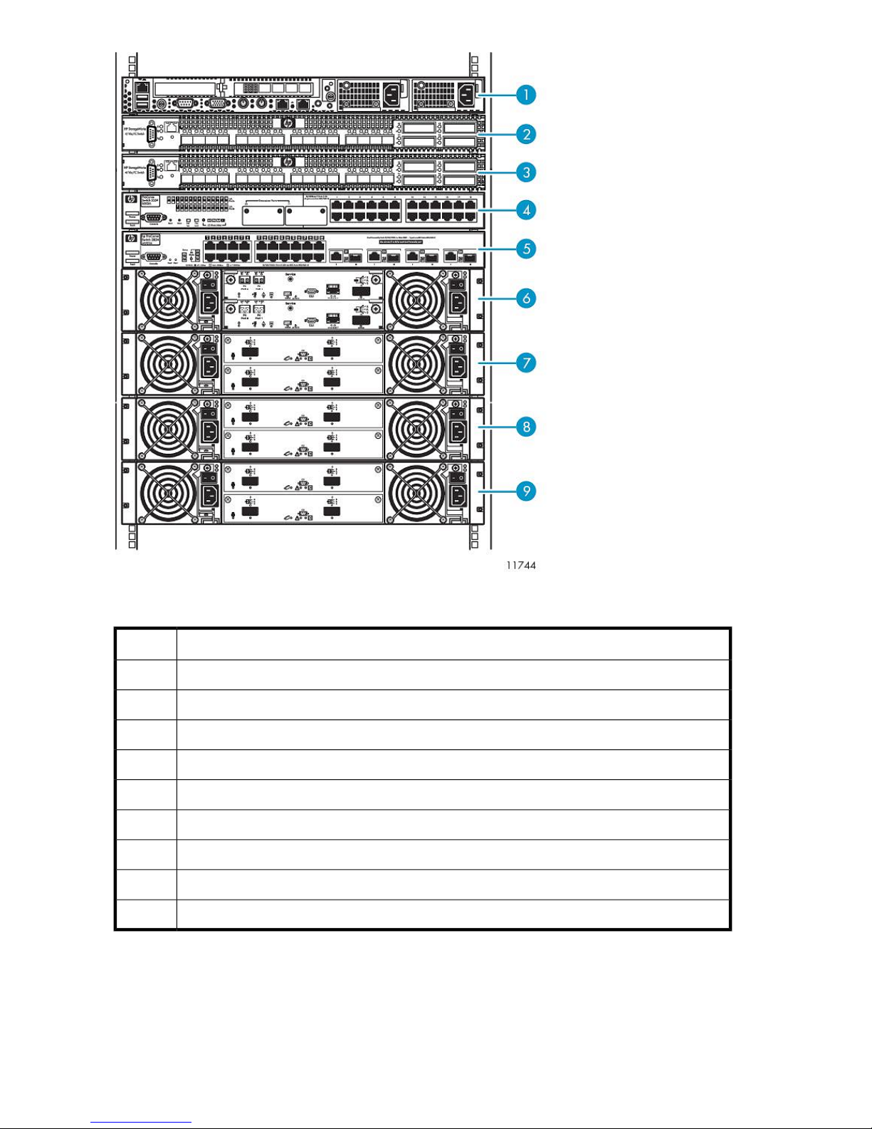
Figure 1 Racked VLS9000 system (32-port connectivity kit shown)
.
DescriptionItem
Node 0, primary node1
FC switch 02
FC switch 13
Ethernet Switch 2510–24 (100 Mb)4
Ethernet Switch 2810–24G (1 Gb)5
Base disk array enclosure6
Expansion disk array enclosure7
Expansion disk array enclosure8
Expansion disk array enclosure9
You can install either the VLS9000 20-port or 32-port connectivity kit with the VLS9000-series. (The
VLS9000 7.5 TB and 10 TB systems omit the connectivity kit.) The 20-port connectivity kit includes
two 10-port Fibre Channel switches and two Ethernet switches. The 32-port connectivity kit includes
Introduction18
Page 19

two 16-port Fibre Channel switches and two Ethernet switches. The number of Fibre Channel ports
available determines the number of arrays and nodes that can be installed. The 32-port connectivity
kit allows you to install more VLS9000 nodes and VLS9000 arrays in your VLS9000-series system
than the 20-port connectivity kit.
VLS9000–series scalability considerations:
• Two Fibre Channel ports (one Fibre Channel port on each Fibre Channel switch) are required for
each VLS9000 node
• Two Fibre Channel ports (one Fibre Channel port on each Fibre Channel switch) are required for
each VLS9000 array
• Up to two VLS9000 arrays may be installed for every VLS9000 node in a VLS9000-series system
• Adding nodes and arrays increases the VLS9000-series storage capacity
• Adding nodes to a system that has more than one array installed for every node increases perform-
ance
If you have a 20–port connectivity kit, you can install a total of ten devices, consisting of a combination
of arrays and nodes. If you have a 32–port connectivity kit, you can install a total of 16 devices.
By interconnecting two 32–port connectivity kits with an interswitch link kit, you can further expand
the scalability of VLS9000–series. See Table 1 and Table 2 for configuration options.
NOTE:
For maximum performance, install one VLS9000 array for every VLS9000 node installed.
For maximum capacity, install two VLS9000 arrays for every VLS9000 node installed.
To add a VLS9000 array, purchase a VLS9000 capacity kit. A VLS9000 capacity kit includes one
VLS9000 array and one capacity license for the VLS9000 array. If you have a 7.5 TB or 10 TB
system, you can add expansion disk array enclosures individually.
See the HP StorageWorks VLS9000 Virtual Library System Quickspec on the HP web site (http://
h18004.www1.hp.com/storage/disk_storage/disk_to_disk/vls/index.html?jumpid=reg_R1002_USEN)
for performance data.
Table 1 VLS9030 capacity (with 2:1 data compression)
2x32-port connectivity kit32-port connectivity kit20-port connectivity kitNodes
1
2
3
4
5
60 TB — 120 TB
(1 — 2 arrays)
120 TB — 240 TB
(2 — 4 arrays)
180 TB — 360 TB
(3 — 6 arrays)
240 TB — 360 TB
(4 — 6 arrays)
300 TB
(5 arrays)
60 TB — 120 TB
(1 — 2 arrays)
120 TB — 240 TB
(2 — 4 arrays)
180 TB — 360 TB
(3 — 6 arrays)
240 TB — 480 TB
(4 — 8 arrays)
300 TB — 600 TB
(5 — 10 arrays)
60 TB — 120 TB
(1 — 2 arrays)
120 TB — 240 TB
(2 — 4 arrays)
180 TB — 360 TB
(3 — 6 arrays)
240 TB — 480 TB
(4 — 8 arrays)
300 TB — 600 TB
(5 — 10 arrays)
HP StorageWorks 19
Page 20

2x32-port connectivity kit32-port connectivity kit20-port connectivity kitNodes
N/A6
N/A7
N/A8
360 TB — 600 TB
(6 — 10 arrays)
420 TB — 540 TB
(7 — 9 arrays)
480 TB
(8 arrays)
Table 2 VLS9040 capacity (with 2:1 data compression)
1
2
3
4
80 TB – 160 TB
(1 – 2 arrays)
160 TB – 320 TB
(2 – 4 arrays)
240 TB – 480 TB
(3 – 6 arrays)
320 TB – 480 TB
(4 – 6 arrays)
80 TB – 160 TB
(1 – 2 arrays)
160 TB – 320 TB
(2 – 4 arrays)
240 TB – 480 TB
(3 – 6 arrays)
320 TB – 640 TB
(4 – 8 arrays)
360 TB — 720 TB
(6 — 12 arrays)
420 TB — 840 TB
(7 — 14 arrays)
480 TB — 960 TB
(8 — 16 arrays)
2x32–port connectivity kit32-port connectivity kit20-port connectivity kitNodes
80 TB – 160 TB
(1 – 2 arrays)
160 TB – 320 TB
(2 – 4 arrays)
240 TB – 480 TB
(3 – 6 arrays)
320 TB – 640 TB
(4 – 8 arrays)
5
400 TB
(5 arrays)
N/A6
N/A7
N/A8
400 TB – 800 TB
(5 – 10 arrays)
480 TB – 800 TB
(6 – 10 arrays)
560 TB – 720 TB
(7 – 9 arrays)
640 TB
(8 arrays)
400 TB – 800 TB
(5 – 10 arrays)
480 TB – 960 TB
(6 – 12 arrays)
560 TB – 1120 TB
(7 – 14 arrays)
640 TB – 1280 TB
(8 – 16 arrays)
Introduction20
Page 21

2 Hardware Installation
This section details the steps to install the VLS hardware from installation preparation to final cabling.
Preparing for the Installation
Tools for Installation
• Two people
• #1 and #2 Phillips screwdriver
• Standard screwdriver
• Allen wrench (provided; used with 6-mm screws and #12-24 x 3/8-inch sockethead screws)
• #3 Pozidrive screwdriver
• 7/16 inch wrench
• Box cutting knife
CAUTION:
Do not use any power tools. They could strip or damage connections.
Taking ESD Precautions
To prevent damaging the system, be aware of the precautions you need to follow when setting up
the system or handling parts. A discharge of static electricity from a finger or other conductor may
damage system boards or other static-sensitive devices. This type of damage may reduce the life
expectancy of the device.
To prevent electrostatic damage:
• Avoid hand contact by transporting and storing products in static-safe containers.
• Keep electrostatic-sensitive parts in their containers until they arrive at static-free workstations.
• Place parts on a grounded surface before removing them from their containers.
• Avoid touching pins, leads, or circuitry.
• Always be properly grounded when touching a static-sensitive component or assembly.
Grounding Methods to Prevent Electrostatic Discharge
Several methods are used for grounding. Use one or more of the following methods when handling
or installing electrostatic-sensitive parts:
• Use a wrist strap connected by a ground cord to a grounded workstation or computer chassis.
Wrist straps are flexible straps with a minimum of 1 megaohm ±10 percent resistance in the
ground cords. To provide proper ground, wear the strap snug against the skin.
HP StorageWorks 21
Page 22

• Use heel straps, toe straps, or boot straps at standing workstations.
Wear the straps on both feet when standing on conductive floors or dissipating floor mats.
• Use conductive field service tools.
• Use a portable field service kit with a folding static-dissipating work mat.
If you do not have any of the suggested equipment for proper grounding, have an authorized reseller
install the part.
For more information on static electricity or assistance with product installation, contact your authorized
reseller.
Unpacking
Place the shipping carton as close to the installation site as possible. Before unpacking the VLS, inspect
the shipping carton for damage that may have occurred during shipment. If you detect any damage,
notify the carrier and HP before unpacking the unit.
Removing the Packing Materials
To unpack the VLS:
1. Open the top of the shipping cartons.
2. Carefully lift the units out of the boxes and remove the packing materials.
3. Place the units on a stable work surface.
NOTE:
Inspect the units for any damage that may have occurred during shipment. If damage is
detected, contact your authorized service representative.
4. Remove the accessory kits and documentation from the shipping cartons. Set them aside for later
use.
5. Place shipping materials back into the shipping cartons.
6. Set the shipping cartons aside for later use.
Rack Planning Resources
The rack resource kit ships with all HP or Compaq branded 9000, 10000, and H9 series racks. A
summary of the content of each resource follows:
• Custom Builder is a web-based service for configuring one or many racks. Rack configurations
can be created using:
• A simple, guided interface
• Build-it-yourself model
• The Installing Rack Products video provides a visual overview of operations required for configuring
a rack with rack-mountable components. It also provides the following important configuration
steps:
• Planning the site
• Installing rack servers and rack options
Hardware Installation22
Page 23

• Cabling servers in a rack
• Coupling multiple racks
• The Rack Products Documentation CD enables you to view, search, and print documentation for
HP and Compaq branded racks and rack options. It also helps you set up and optimize a rack in
a manner that best fits your environment.
Rack Requirements
HP supports the HP 10000 Series racks for use with VLS systems. Other racks might also be suitable,
but have not been tested with the VLS.
Rack Warnings
WARNING!
To reduce the risk of personal injury or damage to the equipment, be sure that:
• The leveling jacks are extended to the floor.
• The full weight of the rack rests on the leveling jacks.
• The stabilizing feet are attached to the rack if it is a single-rack installation.
• The racks are coupled together in multiple-rack installations.
• Only one component is extended at a time. A rack may become unstable if more than one com-
ponent is extended for any reason.
WARNING!
To reduce the risk of personal injury or equipment damage when unloading a rack:
• At least two people are needed to safely unload a rack from a pallet. An empty 42U rack can
weigh as much as 115 kg (253 lb), can stand more than 2.1 m (7 ft) tall, and may become unstable
when being moved on its casters.
• Never stand in front of a rack when it is rolling down the ramp from the pallet. Always handle a
rack from both sides.
Identifying the VLS Shipping Carton Contents
Unpack the VLS shipping cartons and locate the materials and documentation necessary for installing
the VLS. All the rack mounting hardware and documentation necessary for installing a VLS node into
a rack is included in the node shipping carton. All the rack mounting hardware and documentation
necessary for installing a VLS disk array into a rack is included in the disk array shipping carton. All
the rack mounting hardware and documentation necessary for installing a VLS connectivity kit into a
rack is included in the connectivity kit shipping carton. All the documentation necessary for installing
a VLS interswitch link kit into a rack is included in the interswitch link kit shipping carton.
HP StorageWorks 23
Page 24
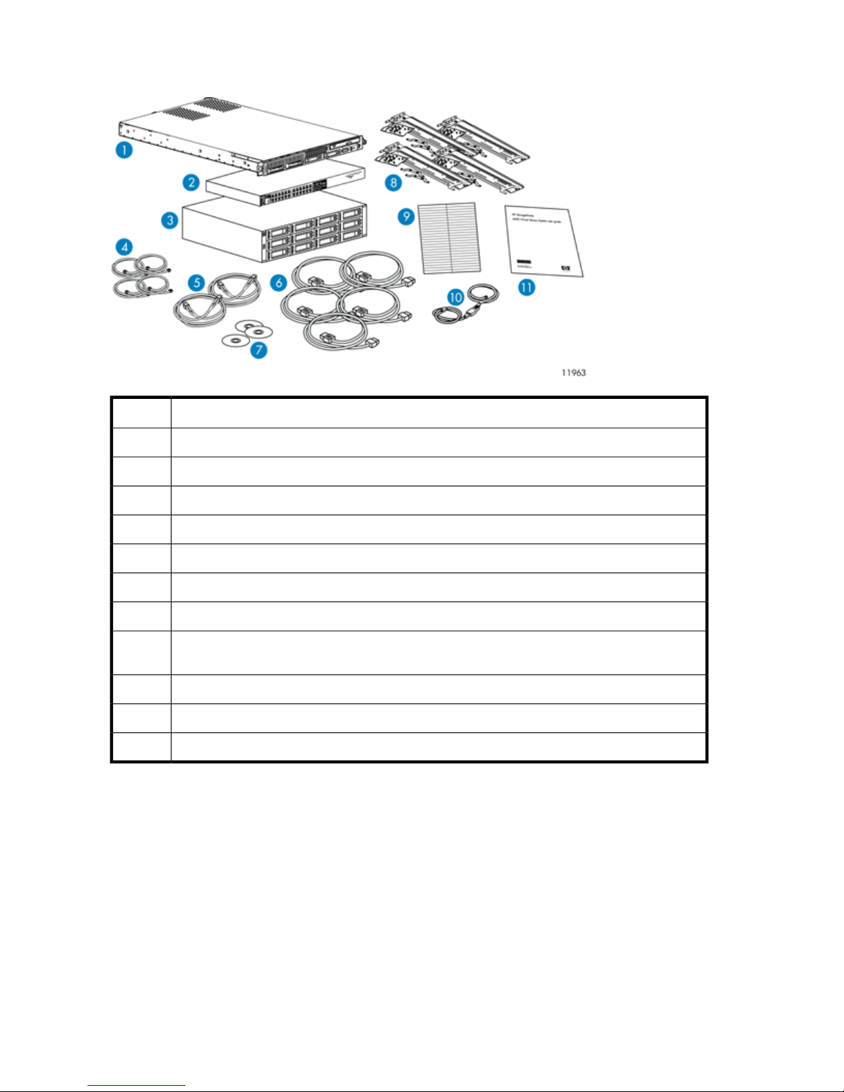
VLS9000 7.5 TB and 10 TB Systems Shipping Carton
DescriptionItem
VLS9000 master node (1)1
Ethernet switch 2510–24 (1)2
Base disk array enclosure (1)3
Ethernet cables (4)4
Fibre Channel cables (2)5
Power cords (5)6
Documentation CD (1) and VLS Quick Restore CD (1)7
8
1U rack mounting hardware kit (2), mounting bracket set (1), 1U cover plate (1), 2U rack mounting
hardware kit (1)
Labels9
USB LAN adapter (1)10
Printed VLS installation poster (1)11
Hardware Installation24
Page 25
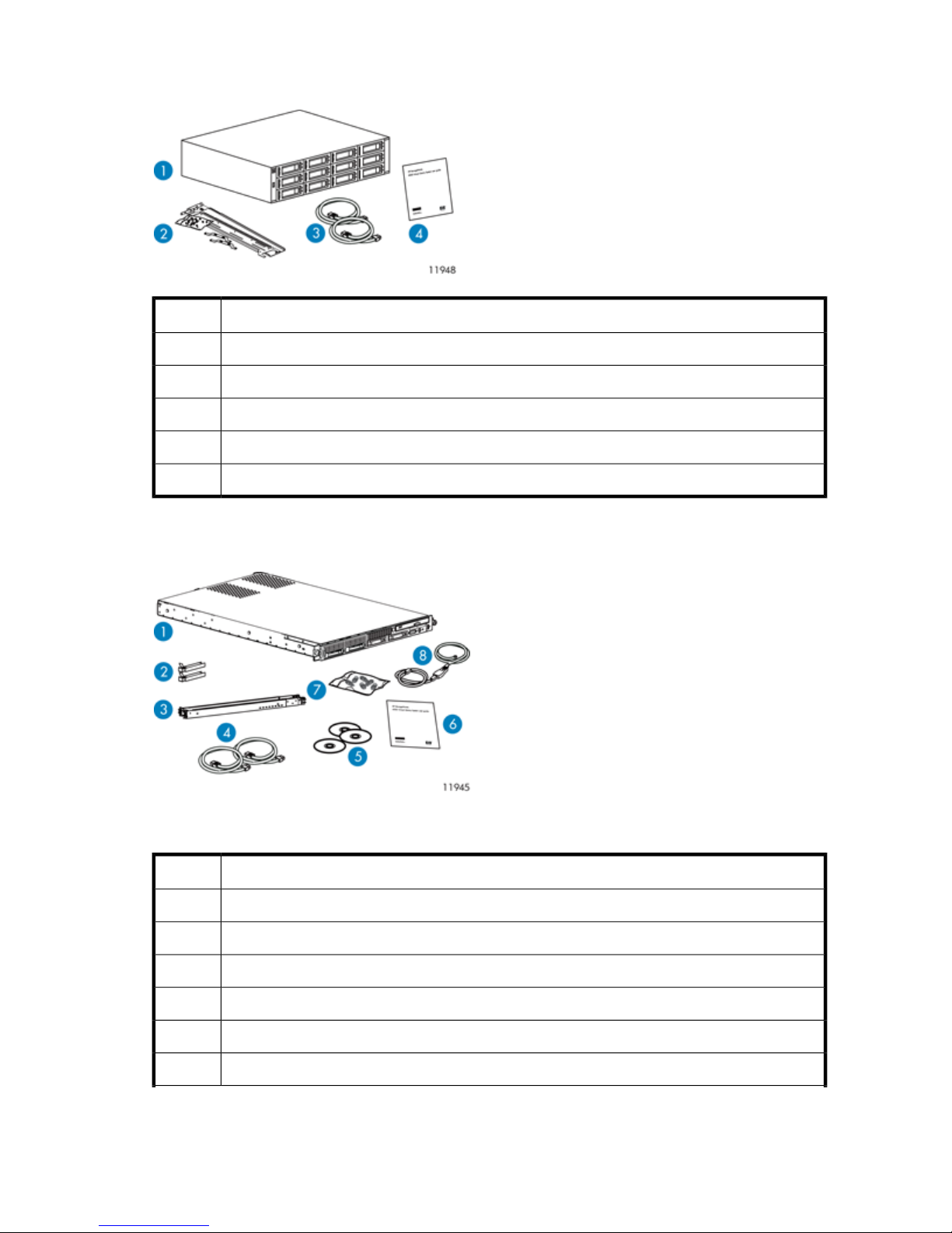
VLS9000 Single Expansion Disk Array Enclosure Shipping Carton
DescriptionItem
VLS9000 expansion disk array enclosure (1)1
SAS cables (2)2
Power cords (2)3
Printed VLS array installation poster (1)4
1U rack mounting hardware kit (1)5
VLS9000 Node Shipping Carton
Figure 2 Identifying contents of the VLS9000 node shipping carton
.
DescriptionItem
VLS9000 node1
FC transceivers (2)2
1U rack mounting hardware kit (1) and documentation3
Power cords (2)4
Documentation CD (1) and VLS Quick Restore CD (1)5
Printed VLS node installation poster (1)6
HP StorageWorks 25
Page 26
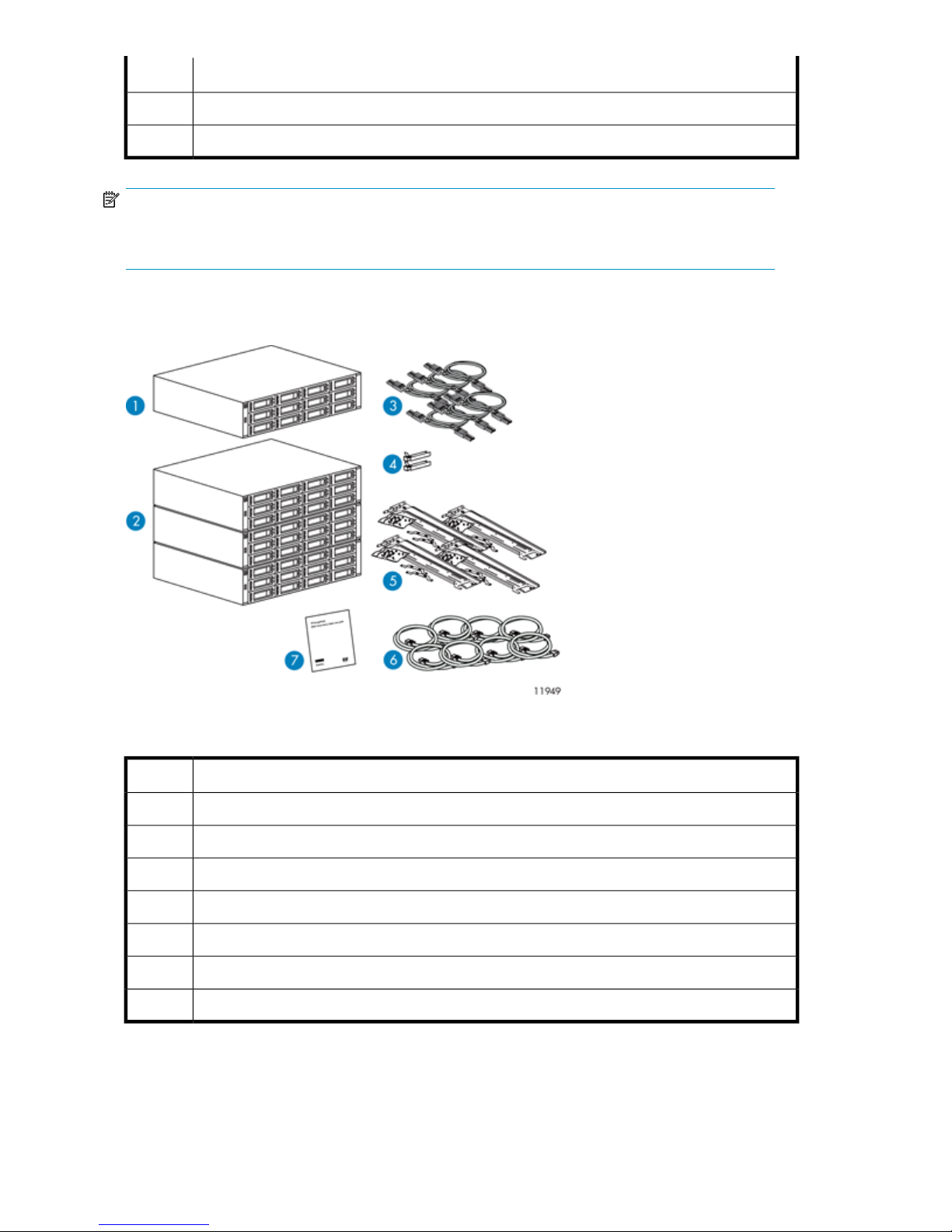
DescriptionItem
Loopback plugs for FC ports7
USB LAN adapter8
NOTE:
In addition to the contents of the shipping cartons, you will also need two Ethernet cables and two
Fibre Channel cables to connect the system.
VLS9000 Array Shipping Carton
Figure 3 Identifying contents of the VLS9000 array shipping carton
.
DescriptionItem
VLS9000 base disk array enclosure (1)1
VLS9000 expansion disk array enclosure (3)2
SAS cables (6)3
FC transceivers (2)4
2U rack mounting hardware kits (4) and documentation5
Power cords (8)6
Printed VLS array installation poster (1)7
Hardware Installation26
Page 27
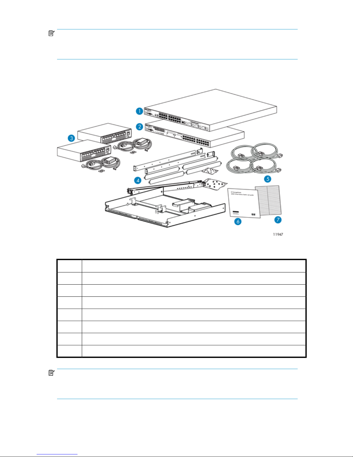
NOTE:
In addition to the contents of the shipping cartons, you will also need two Ethernet cables and two
Fibre Channel cables to connect the system.
VLS9000 20-port Connectivity Kit Shipping Carton
Figure 4 Identifying contents of the VLS9000 20-port connectivity kit shipping carton
.
DescriptionItem
Ethernet Switch 2810–24G (1)1
Ethernet Switch 2510–24 (1)2
Fibre Channel Switches 4/10q (2)3
1U rail kits (2), 1U cover plates (4), rack shelf (1), mounting bracket set (1), and documentation4
Power cords (4)5
Printed VLS connectivity kit installation poster (1)6
Labels7
NOTE:
In addition to the contents of the shipping cartons, you will also need three Ethernet cables to connect
the system.
HP StorageWorks 27
Page 28
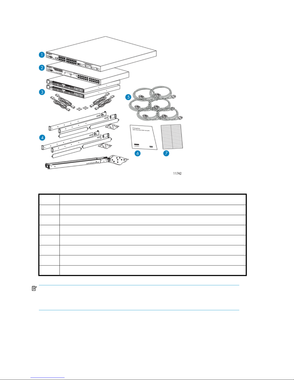
VLS9000 32-port Connectivity Kit Shipping Carton
Figure 5 Identifying contents of the VLS9000 32-port connectivity kit shipping carton
.
DescriptionItem
Ethernet Switch 2810–24G (1)1
Ethernet Switch 2510–24 (1)2
Fibre Channel Switches 4/16q (2)3
1U rail kits (3), 1U cover plates (4), and documentation4
Power cords (6)5
Printed VLS connectivity kit installation poster (1)6
Labels7
NOTE:
In addition to the contents of the shipping cartons, you will also need three Ethernet cables to connect
the system.
Hardware Installation28
Page 29
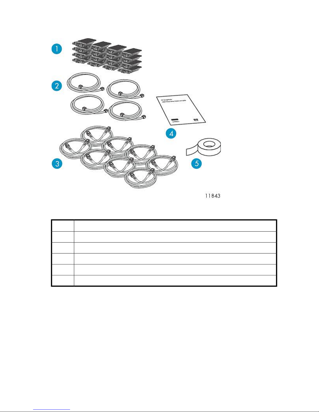
VLS9000 Interswitch Link Kit Shipping Carton
Figure 6 Identifying contents of the VLS9000 interswitch link kit shipping carton
.
DescriptionItem
XPAK transponders (16)1
Ethernet cables (4)2
FC cables (8)3
Printed VLS interswitch link kit installation poster (1)4
Preprinted labels5
VLS9000-series Hardware Installation Overview
HP recommends you install the components of the VLS9000-series as seen in Figure 7:
HP StorageWorks 29
Page 30
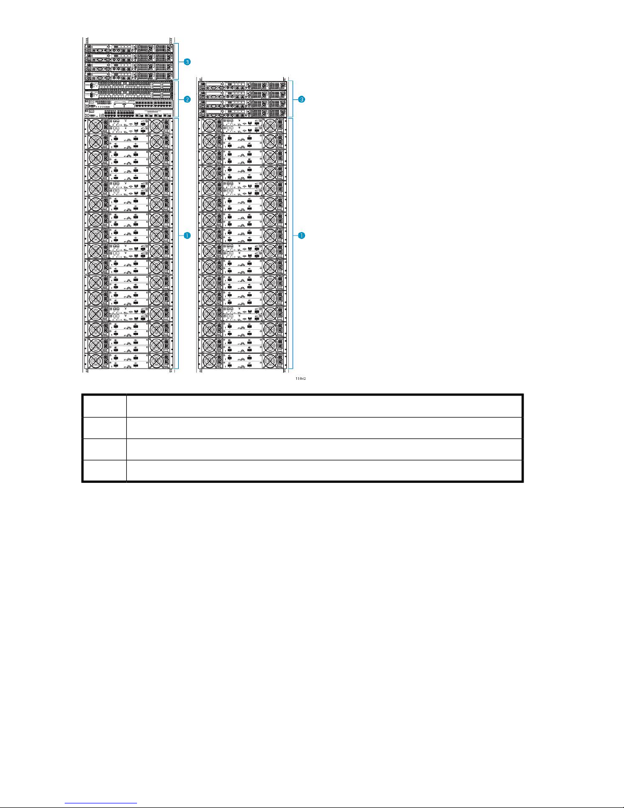
DescriptionItem
VLS9000-series disk arrays1
VLS9000-series Ethernet switch or connectivity kit (32-port kit shown)2
VLS9000-series nodes3
Figure 7 VLS9000-series two-rack configuration
.
The VLS9000-series is a scalable storage solution. For more information on VLS9000-series
configuration options, see VLS9000-series Components.
Whether you are installing one rack or multiple racks of VLS9000-series equipment, the rack mounting
order is essentially the same. See Figure 7 and Installing the VLS Node into a Rack.
Use the following information to understand rack mounting VLS9000-series equipment:
• Depending on the configuration, a VLS9000–series device requires between one and four racks.
If available, install racks two through four next to the first rack. See Figure 8.
Hardware Installation30
Page 31

Figure 8 VLS9000–series four-rack configuration, Racks 1–4 (left to right)
.
• If the racks you are using did not come with PDUs installed, see Installing PDUs before racking
VLS9000–series equipment.
• Install a maximum of four arrays in each rack, starting above the PDUs at rack positions 3 and 4.
See Installing the Disk Array Enclosures into a Rack.
• Install an Ethernet switch or 32– or 20–port connectivity kit above the arrays in the first rack. See
the instructions beginning in Installing Fibre Channel Switches 4/10q onto Racking Shelf.
If available, install a second 32–port connectivity kit above the arrays in rack three.
• Install a maximum of four nodes at the top of the rack, above the arrays, and the connectivity kit,
if present. See Installing the VLS Node into a Rack.
• Unless directed to do so, do not leave spaces between devices.
After racking all VLS9000-series equipment, see Installing VLS9000 Cables. If the configuration you
are installing consists of one Ethernet switch or connectivity kit, cabling the system completes the
installation.
If the configuration you are installing consists of two 32-port connectivity kits, you must additionally
connect the connectivity kit in rack one to the connectivity kit in rack three. See Installing VLS9000-series
Interswitch Link Kit. The two cabled connectivity kits function as one logical set of switches.
Installing the VLS9000 7.5 TB and 10 TB Systems
To install the 7.5 TB and 10 TB systems, use the following sections. The installation is the same as for
other VLS9000 systems except where noted. Not all of the information will apply.
When installing disk array enclosures for the 7.5 TB and 10 TB systems, keep in mind that you install
the base disk array enclosure first and install expansion disk array enclosures as you purchase them
working down the rack. This differs from other VLS9000 systems where you install the expansion disk
array enclosures at the bottom of the rack and work up to the base disk array enclosure.
HP StorageWorks 31
Page 32

The expansion disk array enclosures come with capacity options of either 7.5 TB or 10 TB. Install the
same capacity expansion disk array enclosures as you purchased for the base disk array enclosure;
mixing 7.5 TB capacity with 10 TB capacity is not recommended.
Installing PDUs
If the rack you are using already has PDUs (power distribution units) installed, skip this procedure.
Hardware Installation32
Page 33

1. Determine the number of PDUs to install.
• The number of PDUs you install is based on the number of arrays to install.
• Install up to four arrays in one rack.
• Install up to a maximum of four additional arrays in racks two through four.
Use the following table to determine how many PDUs to install:
PDMsPDUsArrays
NOTE:
PDUs are installed in pairs.
PDMs (power distribution modules) are the power outlet strips that connect to the PDUs.
EuropeNorth AmericaEuropeNorth America
66221
66222
610443
810444
Figure 9 PDU and PDM locations
.
HP StorageWorks 33
Page 34

NOTE:
Steps 2 through 6 correspond to the PDUs and PDMs called out in Figure 9.
2. Install the first two PDUs in the front rack positions 1 and 2.
If installing four PDUs, install the second pair in the rear rack positions 1 and 2.
NOTE:
To ensure high availability, HP recommends connecting half of the PDMs to one power
source, and the other half to a second power source.
3. Install PDMs from the front PDU in rack position 1 to the lower left rack doorway.
4. Install PDMs from the front PDU in rack position 2 to the lower right rack doorway.
5. If you installed four PDUs:
Install PDMs from the rear PDU in rack position 1 to the upper left rack doorway.
Install PDMs from the rear PDU in rack position 2 to the upper right rack doorway.
6. If needed, you may install a fifth PDM on the upper left and right rack doorway beside the top
PDM for sites in North America, but do not exceed five PDMs per side. Do not exceed four PDMs
per side for sites in Europe.
WARNING!
• In North America – Do not plug more than three PDMs into a PDU.
• In Europe – Do not plug more than two PDMs into a PDU.
Installing the VLS9000 Node into a Rack
HP recommends the following racking configurations installed from bottom to top:
Hardware Installation34
Page 35

Figure 10 Rack one recommended rack configuration (32-port connectivity kit shown)
.
DescriptionItem
Node 3, secondary node1
Node 2, secondary node2
Node 1, secondary node3
Node 0, primary node4
5
Fibre Channel switch 0
1
HP StorageWorks 35
Page 36

DescriptionItem
6
Fibre Channel switch 1
2
Ethernet Switch 2510-24 (100 Mb)7
Ethernet Switch 2810-24G (1 Gb)8
array 39
array 210
array 111
array 012
1
If installing 10-port FC switches, leave this rack slot empty.
2
If installing 10-port FC switches, install both FC switches here.
Hardware Installation36
Page 37

Figure 11 Rack two recommended rack configuration
.
DescriptionItem
Node 7, secondary node1
Node 6, secondary node2
Node 5, secondary node3
HP StorageWorks 37
Page 38

DescriptionItem
Node 4, primary node4
array 75
array 66
array 57
array 48
Hardware Installation38
Page 39

Figure 12 Rack three recommended rack configuration
.
DescriptionItem
Fibre Channel switch 01
Fibre Channel switch 12
Ethernet Switch 2510-24 (100 Mb)3
HP StorageWorks 39
Page 40

DescriptionItem
Ethernet Switch 2810-24G (1 Gb)4
array 115
array 106
array 97
array 88
Figure 13 Rack four recommended rack configuration
.
Hardware Installation40
Page 41

DescriptionItem
array 151
array 142
array 133
array 124
NOTE:
Install components starting at rack position 3, working toward the top of the rack. Starting at the
bottom distributes the weight correctly in the cabinet. Rack positions 1 and 2 are reserved for PDUs.
See Installing PDUs.
NOTE:
If you are installing the node into a telco rack, order the appropriate option kit at the RackSolutions.com
web site: http://www.racksolutions.com/hp. Follow the instructions on the web site to install the rack
brackets.
Install the node in the rack as follows:
1. Locate the rail kit — part number 360332–003.
Install the two outer slide rails to the rack. The outer rails are marked “FRONT” and “REAR.”
On both sides of the rack, align the rail holes with the holes in the rack and secure.
HP StorageWorks 41
Page 42

2. Attach the inner rails to the sides of the node.
Align the holes in the rail with the round tabs on the side of the node.
NOTE:
The inner rails are identical.
The word “FRONT” should face away from the node, but will appear updside-down on one
side.
3. Align the rails on the node with the rails in the rack, and slide the node fully into the rack.
4. Tighten the thumbscrews.
Installing Fibre Channel Switches 4/10q onto Racking Shelf
Locate the following items and set them aside on a stable work surface:
• Two Fibre Channel Switches 4/10q, two external power supplies, and two AC power cords
• 1U rails, adjustable mounting flanges, 1U cover plates (2), and hardware to secure the rails to
the rack
• Racking shelf and screws to secure rails to the shelf
To install the 4/10q switches onto the racking shelf:
1. Slide the power supply into the left bay of the power supply housing.
The DC power side faces the inside of the racking shelf. Hold the DC power cord so that it is not
abraded or crimped.
To ease the insertion of the power supply, slightly lift the outside edge of the power supply
housing.
Hardware Installation42
Page 43

2. Repeat step 1 for the other power supply and the right bay.
3. When both power supplies are in position, press down the locking tab near the back edge of
the power supply housing (see magnified view in figure above).
4. Temporarily remove the retaining brace from the edge of the racking shelf.
5. Slide one switch onto the left side of the racking shelf, and then slide the second switch onto the
right side of the racking shelf.
Use the guide posts on the bottom of the racking shelf to align the switches and ensure that the
prongs on the backstop engage the slots on the back of the switch.
6. When both switches are in position, replace the retaining brace.
7. Connect the DC cord of the power supply to the back of the switch and then secure.
8. Connect the AC power cord to the back of the power supply.
9. Attach the rails to the sides of the shelf assembly, using screws provided with the racking shelf.
Attaching Rails to Fibre Channel Switches 4/16q
1. Locate the following items and set them aside on a stable work surface:
• Two Fibre Channel switches 4/16q and two AC power cords
• 1 U rails, adjustable mounting flanges, two 1U cover plates, and hardware to secure the rails
to the rack
• Screws to secure rails to the switch
2. Connect the two AC power cords to the two power supplies on the rear of both 4/16q switches.
HP StorageWorks 43
Page 44
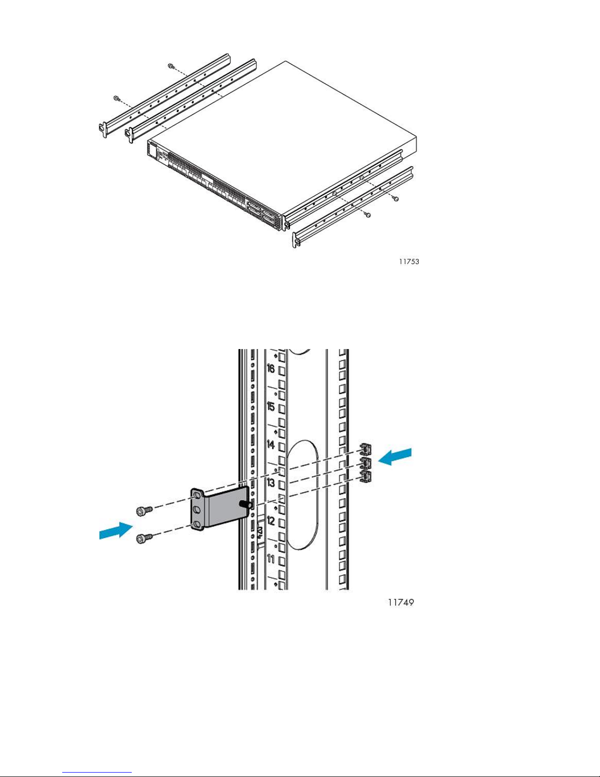
3. Attach the rails to the sides of the switches, using screws provided.
Racking Fibre Channel Switches 4/10q or 4/16q
1. On the rack vertical posts, mark the holes that will be used by the rail flanges (three on each
front vertical post and two on each rear vertical post). Then, from the inside of each vertical post,
insert a cage-nut into each marked hole.
2. From the front of the rack, secure the adjustable mounting flanges to the marked holes, using
screws shipped with the rails.
Hardware Installation44
Page 45
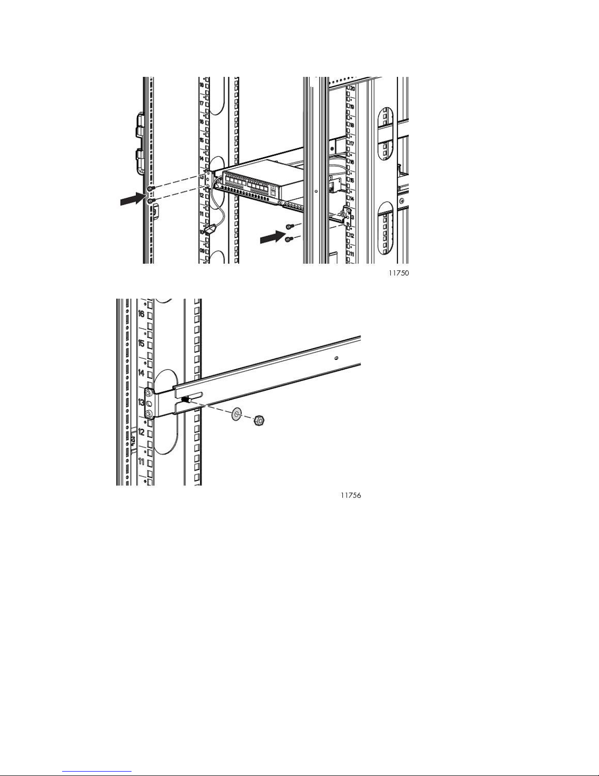
3. From the rear of the rack, slide the racking shelf assembly with Fibre Channel Switches 4/10q
or 4/16q into the rack, sliding the rail ends onto the adjustable mounting flanges already installed
in the front rack vertical posts.
4. When the rail flanges are flush with the rack vertical posts, secure them to the rack.
HP StorageWorks 45
Page 46
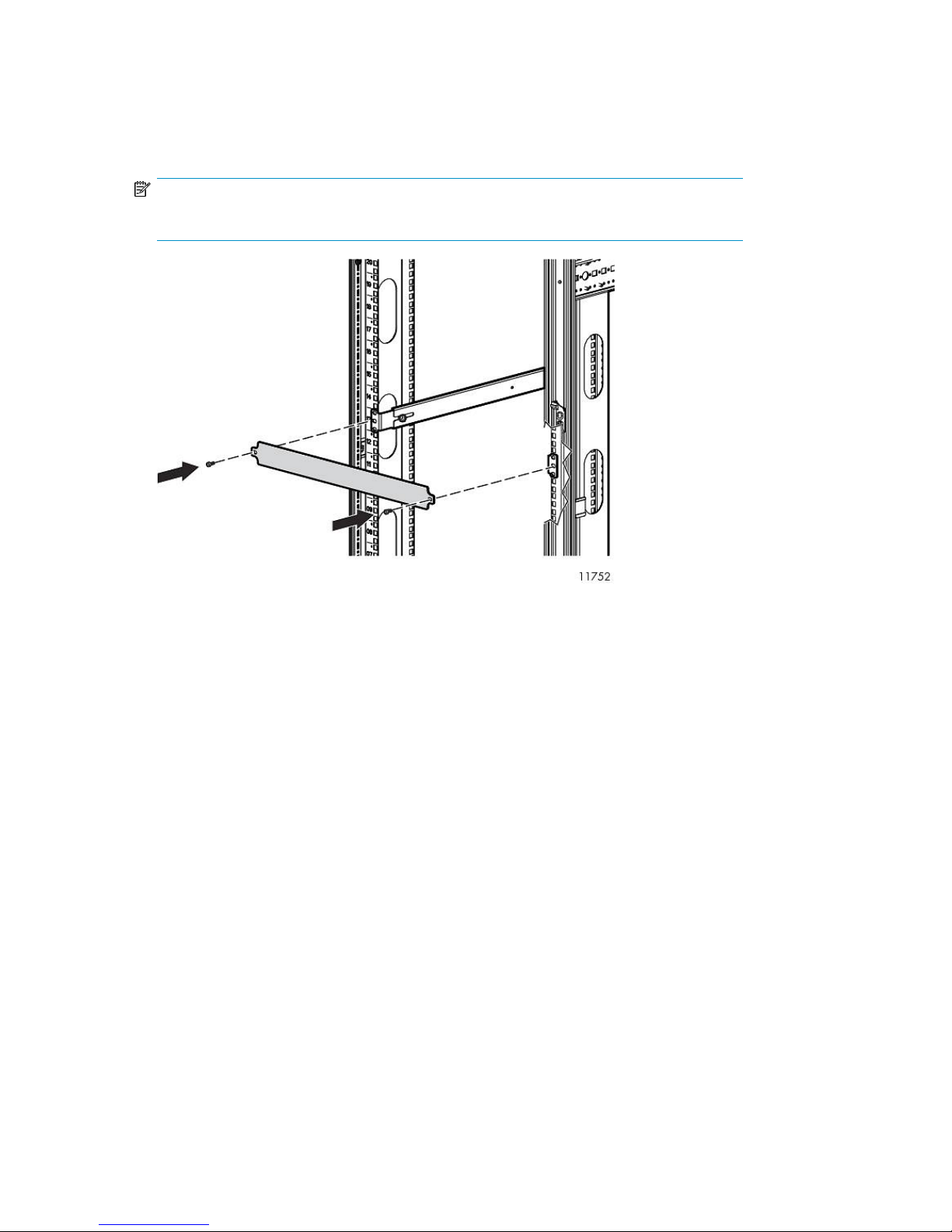
5. Attach two 1U cover plates to the front of the rack.
Attach one 1U cover plate in front of each Fibre Channel Switch 4/16q.
Attach one in front of the Fibre Channel Switches 4/10q and one over the blank space above
the Fibre Channel Switches 4/10q.
NOTE:
With Fibre Channel Switch 4/10q, a blank space is reserved for future expansion.
6. Plug the AC power cords into an AC power source.
Route one cord to a PDM mounted on the right vertical post, and the other to a PDM on the left
vertical post.
Installing the 1 Gb Ethernet Switch 2810–24G into a Rack
Installing the switch into the rack involves installing the cage nuts and rail flanges, attaching the rails
to the switch, and installing the switch into the rack.
Hardware Installation46
Page 47
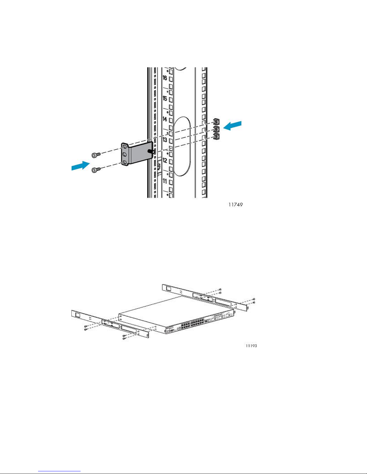
Installing Cage Nuts and Rail Flanges in the Rack
1. On the rack vertical posts, mark the holes (three on each front vertical post and two on each rear
vertical post) that will be used by the rail flanges. Then, from the inside of each vertical post,
insert a cage-nut into each marked hole.
2. From the front of the rack, secure the mounting flanges to the marked holes, using screws shipped
with the rails.
3. Attach a washer and nut to the posts at the end of each mounting flange. Leave them loose and
towards the open edge of the post.
Attaching Rails to the Ethernet Switch 2810-24G
1. Align the rail with the switch. The two holes at the front of the rail must align with the two holes
at the front of the switch. The bracket end of the rail is towards the front of the switch.
2. Insert two of the pan-head screws through the rail and into the switch at the front of the switch.
Tighten the screws.
3. Insert two of the pan-head screws through the appropriate holes in the rail and into the switch
at the back of the switch. Tighten the screws.
4. Perform these steps again to install the other rail on the other side of the switch.
HP StorageWorks 47
Page 48

Installing Ethernet Switch 2810-24G in Rack
1. From the back of the rack, align the grooved ends of the switch rails with the posts on the mounting
flanges. Placing the grooved ends between the mounting flange and the loose washer and nut
provides guidance.
2. Slide the switch fully into the rack.
3. Tighten the washer and nut on both sides of the rack to secure the switch rails to the mounting
flanges.
4. From the back of the rack, on each side of the switch, insert an M5 screw through the holes in
the rail and into the holes in the rack.
5. Tighten the M5 screws to secure the switch to the rack.
6. Attach a power cable to the switch's power supply.
7. Plug the power cable into an AC power source.
8. Route the power cable through the left side of the rack and plug it into a PDM.
9. Attach a 1U cover plate to the front of the rack.
Hardware Installation48
Page 49

Installing the 100 Mb Ethernet Switch 2510–24 into a Rack
NOTE:
There are no rails associated with this switch.
1. If the metal mounting brackets are not attached to the switch, attach them as follows:
a. Align the brackets so that the four screw holes are against the side of the switch. The side
of the bracket with two screw holes extends from the switch and aligns with the front of the
bezel.
NOTE:
When installed, the switch sits flush with Ethernet Switch 2810–24G.
b. Adjust alignment so that the holes in the side of the mounting bracket line up with the holes
in the switch.
c. Use a Phillips (cross-head) screwdriver and the eight M4 screws (included) to attach the
mounting brackets to the switch.
d. Attach cap nuts to the vertical posts where the mounting brackets attach to the rack.
2. On each side of the switch, secure the mounting bracket to the vertical posts with a Phillips screw.
3. Attach a power cable to the switch's power supply.
4. Route the power cable through the right side of the rack and plug it into a PDM.
5. Attach a power cable to the switch's power supply.
6. Attach a 1U cover plate to the front of the rack.
HP StorageWorks 49
Page 50

Installing the Disk Array Enclosures into a Rack
This section describes how to install the disk array enclosures into a rack.
Rack Mounting Requirements
Each disk array enclosure requires a vertical rack space of 2U (equivalent to 89 mm, or 3.5 inches).
Install three expansion disk array enclosures for the first array (array 0) in the rack positions 3 and
4. Starting at the bottom distributes the weight correctly in the cabinet. See Figure 14. Rack positions
1 and 2 are reserved for PDUs. See Installing PDUs. Next, install a base disk array enclosure in the
slots just above the expansion disk array enclosures. Repeat for the next array. Install up to four arrays
in a rack. Install the fifth through eighth arrays (if available) at the bottom of a second rack. Install
the ninth through twelfth arrays (if available) in a third rack. Install the thirteenth through sixteenth
arrays (if available) in a fourth rack.
If you have the base VLS9000 7.5 TB or 10 TB system and you anticipate adding more disk array
enclosures in the future, consider leaving up to three 2U spaces open at the bottom of the rack. This
eliminates having to reinstall existing components as you expand.
Hardware Installation50
Page 51

Figure 14 VLS9000 array rack configuration
.
DescriptionItemDescriptionItem
array 1, expansion disk array 29array 3, expansion disk array 21
HP StorageWorks 51
Page 52

Mounting a Disk Array Enclosure into a Rack
WARNING!
The disk array weighs 33.6 kg (74 lb) full. At least two people are required to lift, move,
and install the disk array.
If only one person is to perform the installation, remove the power modules and hard drives from a
disk array enclosure before installing it, and if possible position it on top of another device or shelf
in the rack to hold it as you attach all the brackets.
DescriptionItemDescriptionItem
array 1, expansion disk array 110array 3, expansion disk array 12
array 1, expansion disk array 011array 3, expansion disk array 03
array 1, base disk array12array 3, base disk array4
array 0, expansion disk array 213array 2, expansion disk array 25
array 0, expansion disk array 114array 2, expansion disk array 16
array 0, expansion disk array 015array 2, expansion disk array 07
array 0, base disk array16array 2, base disk array8
CAUTION:
When positioning a disk array enclosure in the rack, ensure the air vents at the front and back of the
enclosure are not blocked.
Hardware Installation52
Page 53

1. Locate the cage nuts from the rack mounting hardware kit contents.
a. Start at rack positions 3 and 4.
b. Install a cage nut in the middle hole of each position on the front vertical posts for a total of
two on each side.
c. On the left front post, between the two cage nuts just installed, install a cage nut in the bottom
hole.
d. On the right front post, between the two cage nuts just installed, install a cage nut in the top
hole. See Figure 15.
Figure 15 Installing the cage nuts
.
e. Repeat this procedure on the front vertical posts for each 2U enclosure to be installed.
f. On the rear vertical posts, starting at rack positions 3 and 4, install a cage nut in the middle
hole of each position for each 2U enclosure to be installed.
HP StorageWorks 53
Page 54

2. Locate the enclosure side brackets and the #8-32 x 3/16-inch flathead screws from the rack
mounting hardware kit contents.
NOTE:
The right and left side enclosure brackets are identical. Install the brackets with the beveled
slots facing away from the disk array enclosures.
a. Position the enclosure side bracket with the long edge down, and the arms flush with the
top of the enclosure.
b. Line up the outermost beveled slots of the enclosure side bracket with the rear holes in the
disk array enclosure. The rear arm extends slightly past the back of the enclosure.
c. Install two #8-32 x 3/16-inch flathead screws into the slots. Tighten both screws.
NOTE:
Using screws longer than #8-32 x 3/16-inch may result in interference with the power
supply.
d. Repeat this procedure for the other side bracket, and for each enclosure to be added.
Hardware Installation54
Page 55

3. Locate the two pieces that comprise a rail, and the #8-32 x 3/8-inch flathead screws from the
rack mounting hardware kit contents.
NOTE:
The front rail piece has three long, beveled slots. The rear rail piece has holes.
a. To attach the two rail pieces, slide the rear rail piece behind the front rail piece so the
brackets are at opposite ends and bend away from you.
b. Counting from the end that slides behind the front rail, position the rear rail so its first, third,
and fifth holes are centered in the beveled slots of the front rail.
c. Install but do not completely tighten three #8-32 x 3/8-inch flathead screws into the slots.
Tighten them when instructed to do so.
d. Install rail hangers in the top and bottom holes of the front rail bracket and in the center hole
of the rear rail bracket.
e. Repeat this procedure for the other side rail, and for each enclosure to be added.
HP StorageWorks 55
Page 56

4. Locate the #10–32 1/2–inch flathead and #10–32 5/8 truss head screws from the rack mounting
hardware kit contents.
a. Start at rack positions 3 and 4.
b. On one front vertical post, insert the rail hangers of the front rail bracket into the top and
bottom positions of the 2U section of post.
c. Install one #10–32 1/2–inch flathead screw into the bracket slot slightly offset from center.
Do not tighten the screw completely.
d. In the rear of the rack, keeping the rail level, insert the rail hanger into the rear vertical post.
e. Push the bracket to the outside of the rack until snug.
f. Install two #10–32 5/8–inch truss head screws into the top and bottom positions of the rear
rail bracket. Tighten the screws.
g. In the front of the rack, push the bracket to the outside of the rack until snug. Tighten the
screw in the front rail bracket.
h. Tighten the flathead screws connecting the front and rear rail brackets.
i. Repeat this procedure on the other side of the rack, and for each enclosure to be added.
CAUTION:
Lifting and positioning a disk array enclosure requires two people. If you are installing disk
array enclosures alone, use a mechanical lift or some other device on which to rest the
enclosure.
Hardware Installation56
Page 57

5. Install an expansion disk array enclosure in rack positions 3 and 4, immediately above the PDUs.
Lift the enclosure and slide it onto the rail ledges you previously installed.
a. Attach the front of the enclosure to the front vertical posts using two #10–32 x 3/4–inch
truss head screws on each side. Do not tighten the screws completely.
b. In the rear of the rack, align the enclosure side bracket arm holes with the holes in the rail.
Install two #6-32 x 1/4 panhead screws. Tighten the screws.
NOTE:
You may need to remove the power supplies to install these screws.
c. Tighten the screws in the front of the enclosure.
d. Repeat this procedure to install each additional disk array enclosure above the previous
one.
Installing Power Cables
To connect array power cables:
1. Verify that both power switches are in the off position for each enclosure in the rack.
HP StorageWorks 57
Page 58

2. Locate the AC power cords.
IMPORTANT:
Equally distribute the current between the PDMs.
3. Connect a black power cable to the left power supply of each enclosure and into a PDM mounted
on the left vertical post
4. Connect a gray power cable to the right power supply of each enclosure and into a PDM mounted
on the right vertical post.
Installing VLS9000 Cables
To install VLS9000 cables, follow the instructions in the order of the sections presented below.
Cabling the Nodes
Figure 16 Nodes port cabling
.
DescriptionItem
FC host port, port 11
FC host port, port 22
FC storage port, port 3, on primary node connects to port 0 of Fibre Channel switch #13
FC storage port, port 4, on primary node connects to port 0 of Fibre Channel switch #24
USB connector, on primary node connects to USB/Ethernet adapter, then to port 1 of switch 2510–245
Serial connector to access CLI6
Video connector7
Keyboard connector8
NIC 1, on primary node only connects to the customer-provided external network9
NIC 2, on primary node connects to port 1 of switch 2810–24G10
Power supply 111
Power supply 212
Hardware Installation58
Page 59

1. Connect one end of a USB connector to the USB port on the node. Connect the other end to the
USB/Ethernet adapter. Connect a 1 meter Ethernet cable to the adapter, then connect the Ethernet
cable to port 1 of Switch 2510–24.
Secure the USB/Ethernet adapter to the upper left inside rack brace.
2. If installing more than one node, start with node 0 and work upwards repeating this procedure.
Connect the Ethernet cables sequentially, working right from port 1 on switch 2510–24.
Secure additional Ethernet cables to the upper left inside rack brace.
3. Connect a 1 meter Ethernet cable from NIC 2 on the node to port 1 of Ethernet Switch 2810–24G.
4. If installing more than one node, connect Ethernet cables from NIC 2 of each node, starting with
node 0 and working up. Working sequentially, connect the other end of the Ethernet cables to
ports 2 through 4 on Ethernet Switch 2810–24G.
IMPORTANT:
Do not touch the Fibre Channel cable tips.
Do not secure Fibre Channel cable with cable ties.
5. Connect a Fibre Channel cable from Fibre Channel port 3 on the node to Fibre Channel switch
#1, port 0.
6. For multi-node setups, repeat step 5 for each secondary node, working sequentially from left to
right on Fibre Channel switch #1.
7. Connect a Fibre Channel cable from Fibre Channel port 4 on the node to Fibre Channel switch
#2, Fibre Channel port 0.
8. For multi-node setups, repeat step 7 for each secondary node, working sequentially from left to
right on Fibre Channel switch #2.
9. Using Velcro, secure the cables connected in steps 3 through 8 to the left side of the rack.
10. Install loopback plugs on the nodes in any unused Fibre Channel ports.
HP StorageWorks 59
Page 60
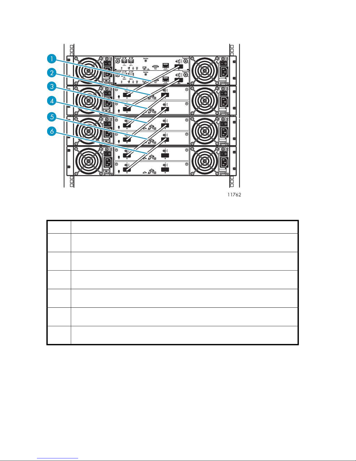
Cabling Disk Array Enclosures
Figure 17 Disk array enclosure SAS port cabling
.
DescriptionItem
1
2
3
4
5
6
SAS cable, SAS port 0 of RAID controller 0 of base disk array connects to SAS port 0, input port,
of expansion controller 0 of expansion disk array 0
SAS cable, SAS port 0 of RAID controller 1 of base disk array connects to SAS port 0, input port,
of expansion controller 1 of expansion disk array 0
SAS cable, SAS port 1, output port, of expansion controller 0 of expansion disk array 0 connects
to SAS port 0, input port, of expansion controller 0 of expansion disk array 1
SAS cable, SAS port 1, output port, of expansion controller 1 of expansion disk array 0 connects
to SAS port 0, input port, of expansion controller 1 of expansion disk array 1
SAS cable, SAS port 1, output port, of expansion controller 0 of expansion disk array 1 connects
to SAS port 0, input port, of expansion controller 0 of expansion disk array 2
SAS cable, SAS port 1, output port, of expansion controller 1 of expansion disk array 1 connects
to SAS port 0, input port, of expansion controller 1 of expansion disk array 2
Locate the SAS cables included in the array kit contents.
Remove the tape and end caps from the SAS cables before installing.
Verify that both power switches are off for each disk array enclosure in the rack.
Starting at the enclosure immediately below Ethernet Switch 2810–24G:
1. Connect one end of a SAS cable to RAID controller 0 of the base disk array enclosure. Connect
the other end to SAS input port of expansion controller 0 of expansion disk array enclosure 0.
Hardware Installation60
Page 61
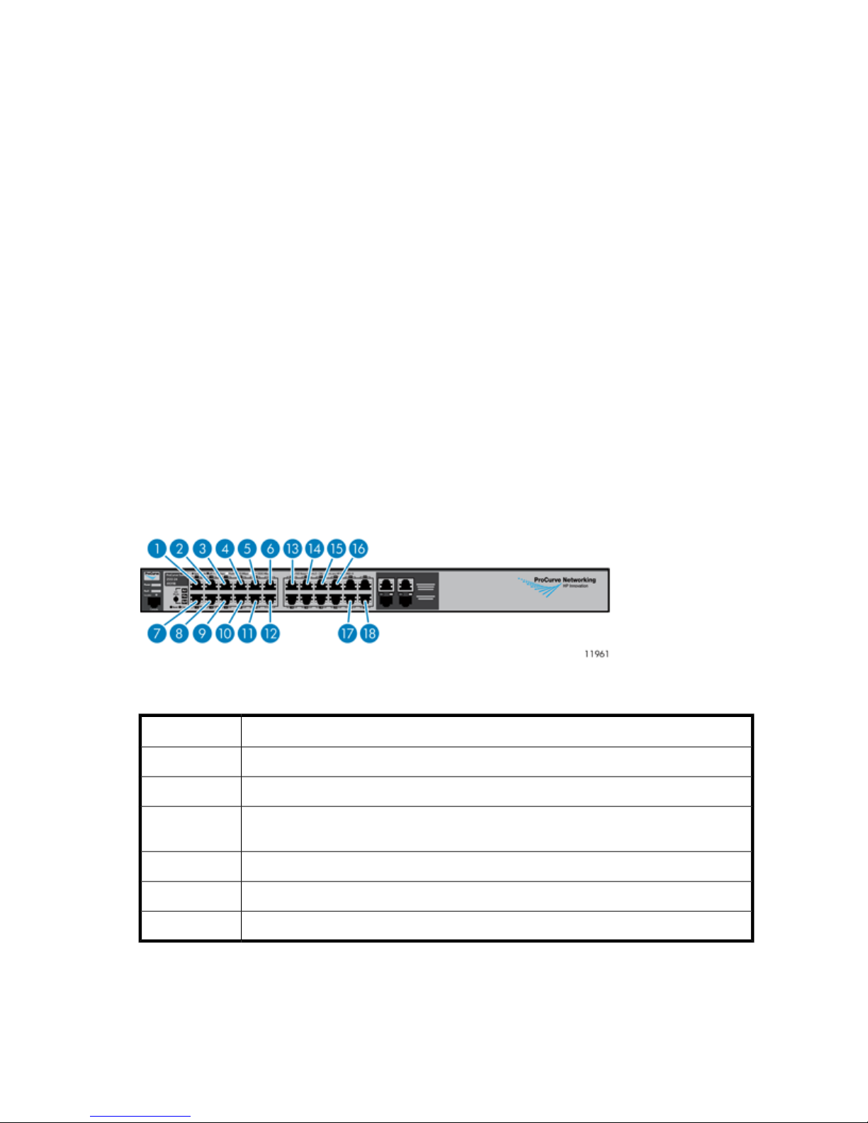
2. Connect one end of a SAS cable to RAID controller 1 of the base disk array enclosure. Connect
the other end to SAS input port of expansion controller 1 of expansion disk array enclosure 0.
3. Connect one end of a SAS cable to SAS output port of expansion controller 0 of the expansion
disk array enclosure 0. Connect the other end to SAS input port of expansion controller 0 of
expansion disk array enclosure 1.
4. Connect one end of a SAS cable to SAS output port of expansion controller 1 of the expansion
disk array enclosure 0. Connect the other end to SAS input port of expansion controller 1 of
expansion disk array enclosure 1.
5. Connect one end of a SAS cable to SAS output port of expansion controller 0 of the expansion
disk array enclosure 1. Connect the other end to SAS input port of expansion controller 0 of
expansion disk array enclosure 2.
6. Connect one end of a SAS cable to SAS output port of expansion controller 1 of the expansion
disk array enclosure 1. Connect the other end to SAS input port of expansion controller 1 of
expansion disk array enclosure 2.
7. Connect black power cables to power module on the left.
8. Route the black power cables through the left side of the rack and connect them to a PDM.
9. Connect gray power cables to the power modules on the right.
10. Route the gray power cables through the right side of the rack and connect them to a PDM.
11. Repeat steps 1 — 10 for each array.
12. Secure the SAS cables of each array together with a Velcro tie.
Cabling Ethernet Switch 2510–24
Figure 18 Ethernet Switch 2510–24 port cabling
.
DescriptionItem
Ethernet cable from USB adapter on primary node1
Ethernet cable from USB adapter on secondary nodes (if present)2—8
9—15
Ethernet cables from RAID controllers 1 of base disk array enclosures of up to 8 arrays (if
present)
Ethernet cable from RAID controller 1 of base disk array enclosure of 1st array (array 0)16
Ethernet cable from Ethernet port of Fibre Channel switch #117
Ethernet cable from port 24 of Ethernet Switch 2810–24G18
1. Connect one end of an Ethernet cable to the Ethernet port of Fibre Channel switch #1. Connect
the other end of the Ethernet cable to port 23 of Switch 2510–24.
HP StorageWorks 61
Page 62

2. Connect one end of an Ethernet cable to port 16 of Ethernet Switch 2510–24. Connect the other
end of the Ethernet cable to RAID controller 1 on the base disk array enclosure of array 0.
3. Working backwards from port 16 on Ethernet Switch 2510–24, connect one end of an Ethernet
cable to the next available Ethernet port. Connect the other end of the Ethernet cable to RAID
controller 1 on the base disk array enclosure of array 1.
4. Repeat step 3 to connect all arrays.
NOTE:
Arrays 5 through 8, if present, reside in a separate rack.
5. Secure Ethernet cables with a Velcro tie to the right side of the rack.
Cabling Ethernet Switch 2810–24G
Figure 19 Ethernet Switch 2810–24G port cabling
.
DescriptionItem
Ethernet cable from NIC 2 of primary node1
Ethernet cable from NIC 2 of secondary nodes (if present)2—8
9—15
16
Ethernet cables from Ethernet ports of RAID controller 0 of base disk array enclosures of up
to 8 arrays (if present)
Ethernet cable from Ethernet port of RAID controller 0 of base disk array enclosure of 1st
array (array 0)
Ethernet cable from Fibre Channel switch #217
Ethernet cable from port 24 of Ethernet Switch 2510–2418
1. Connect one end of an Ethernet cable to the Ethernet port of Fibre Channel switch #2. Connect
the other end of the Ethernet cable to port 23 of Switch 2810–24G.
2. Connect one end of an Ethernet cable to port 16 of Ethernet Switch 2810–24G. Connect the
other end of the Ethernet cable to RAID controller 0 on the base disk array enclosure, of first
array (array 0).
3. Working backwards from port 16 on Ethernet Switch 2810–24G, connect one end of an Ethernet
cable to the next available Ethernet port. Connect the other end of the Ethernet cable to RAID
controller 0 on the base disk array enclosure, of the second array (array 1).
Hardware Installation62
Page 63

4. Repeat step 3 for all arrays.
NOTE:
Arrays 5 through 8, if present, reside in a separate rack.
5. Secure Ethernet cables with a Velcro tie to the right side of the rack.
WARNING!
Do not connect cables to unused ports on Ethernet Switches 2810–24G or 2510–24. Doing so could
result in data loss.
Cabling Fibre Channel Switch 4/10q
Figure 20 Fibre Channel Switch 4/10q port cabling
.
Fibre Channel Switch 4/10q #1
DescriptionItem
FC cable from port 3 of primary node1
FC cable from port 3 of secondary nodes (if present)2—4
5
FC cable from port 3 of 5th node (if present), or FC port 0 of RAID controller 0 of 6th array
(if present)
FC cable from FC port 0 of RAID controller 0 of 2nd — 5th arrays (if present)6—9
FC cable from FC port 0 of RAID controller 0 of 1st array (array 0)10
Ethernet cable from port 23 of Ethernet Switch 2510–2411
Fibre Channel Switch 4/10q #2
DescriptionItem
FC cable from port 4 of primary node1
FC cable from port 4 of secondary nodes (if present)2—4
5
FC cable from port 2 of 5th node (if present), or FC port 0 of RAID controller 1 of 6th array
(if present)
HP StorageWorks 63
Page 64

Fibre Channel Switch 4/10q #2
DescriptionItem
FC cable from FC port 0 of RAID controller 1, 2nd — 5th arrays (if present)6—9
FC cable from FC port 0 of RAID controller 1 of 1st array (array 0)10
Ethernet cable from port 23 of Ethernet Switch 2810–24G11
Locate the Fibre Channel cables from the array kit contents.
1. Connect one end of a Fibre Channel cable to Fibre Channel port 9 of Fibre Channel Switch
4/10q #1. Connect the other end of the Fibre Channel cable to Fibre Channel port 0, of RAID
controller 0, of first array (array 0).
2. Connect one end of a Fibre Channel cable to Fibre Channel port 9 of Fibre Channel Switch
4/10q #2. Connect the other end of the Fibre Channel cable to Fibre Channel port 0 of RAID
controller 1 of first array (array 0).
3. With multiple arrays:
a. Working backwards from the last Fibre Channel port on Fibre Channel switch #1, connect
one end of a Fibre Channel cable to the next available Fibre Channel port on Fibre Channel
switch #1. Connect the other end of the Fibre Channel cable to Fibre Channel port 0 of
RAID controller 0 of second array (array 1).
b. Working backwards from the last Fibre Channel port on Fibre Channel switch #2, connect
one end of a Fibre Channel cable to the next available Fibre Channel port on Fibre Channel
switch #2. Connect the other end of the Fibre Channel cable to Fibre Channel port 0 of
RAID controller 1 of second array (array 1).
4. Repeat steps 3 and 4 for all arrays.
5. Secure the Fibre Channel cables installed in this procedure, and the Ethernet cables installed in
the previous procedure together with Velcro ties. Route them to the right side of the rack.
Cabling Fibre Channel Switch 4/16q
Figure 21 Fibre Channel Switch 4/16q port cabling
.
Fibre Channel Switch 4/16q #1
DescriptionItem
Ethernet cable from port 23 of Ethernet Switch 2510–241
FC cable from port 3 of primary node2
FC cable from port 3 of 2nd — 6th nodes (if present)3—7
Hardware Installation64
Page 65

Fibre Channel Switch 4/16q #1
DescriptionItem
8
9
FC cable from port 3 of 7th node (if present), or FC port 0 of RAID controller 0 of 10th array
(if present)
FC cable from port 3 of 8th node (if present), or FC port 0 of RAID controller 0 of 9th array
(if present)
FC cable from FC port 0 of RAID controller 0, 2nd — 8th arrays (if present)10—16
FC cable from FC port 0 of RAID controller 0 of 1st array (array 0)17
Empty, or XPAK transponders from the interswitch link kit (if present)18—21
Fibre Channel Switch 4/16q #2
DescriptionItem
Ethernet cable from port 23 of Ethernet Switch 2810–24G1
FC cable from FC port 4 of primary node2
FC cable from FC port 4 of 2nd — 6th nodes (if present)3—7
8
9
FC cable from FC port 2 of 7th node (if present), or FC port 0, of RAID controller 1 of 10th
array (if present)
FC cable from FC port 2 of 8th node (if present), or FC port 0, of RAID controller 1 of 9th
array (if present)
FC cable from FC port 0 of RAID controller 1, 2nd — 8th arrays (if present)10—16
FC cable from FC port 0 of RAID controller 1 of 1st array (array 0)17
Empty, or XPAK transponders from the interswitch link kit (if present)18—21
Locate 2 meter Fibre Channel cables from the array kit contents.
1. Connect one end of a Fibre Channel cable to port 15 of Fibre Channel Switch 4/16q #1. Connect
the other end of the Fibre Channel cable to Fibre Channel port 0 of RAID controller 0 of the first
array (array 0).
2. Connect one end of a Fibre Channel cable to port 15 of Fibre Channel Switch 4/16q #2. Connect
the other end of the Fibre Channel cable to Fibre Channel port 0 of RAID controller 1 of the first
array (array 0).
3. With multiple arrays:
a. Working backwards from the last Fibre Channel port on Fibre Channel switch #1, connect
one end of a Fibre Channel cable to the next available Fibre Channel port on Fibre Channel
switch #1. Connect the other end of the Fibre Channel cable to Fibre Channel port 0 of
RAID controller 0 of second array (array 1).
b. Working backwards from the last Fibre Channel port on Fibre Channel switch #2, connect
one end of a Fibre Channel cable to the next available Fibre Channel port on Fibre Channel
switch #2. Connect the other end of the Fibre Channel cable to Fibre Channel port 0 of
RAID controller 1 of second array (array 1).
HP StorageWorks 65
Page 66

4. Repeat step 3 for all arrays.
5. Secure the Fibre Channel cables installed in this procedure, and the Ethernet cables installed in
the previous procedure together with Velcro ties. Route them to the right side of the rack.
Management Ports and External Connections
Connect the management ports of Ethernet Switch 2810–24G and Ethernet Switch 2510–24:
1. Locate a 1 meter Ethernet cable.
2. Connect port 24 of Ethernet Switch 2810–24G to port 24 of Ethernet Switch 2510–24.
3. Secure the excess cable to the right side of the rack.
External connections:
NOTE:
Ethernet port 1 (NIC 1), and Fibre Channel ports 1 and 2 on the primary node are only to be used
for external connections.
On the nodes:
1. Connect one end of a Fibre Channel cable to Fibre Channel port 1 on the node. Connect the
other end to the external network.
2. Connect one end of a Fibre Channel cable to Fibre Channel port 2 on the node. Connect the
other end to the external network.
3. Connect one end of an Ethernet cable to NIC 1 on the primary node. Connect the other end to
the external network.
If your configuration contains one connectivity kit, the VLS9000 hardware installation is complete.
Continue installation by configuring the identities of each node and array. See the HP StorageWorks
9000-series Virtual Library System user guide.
If your configuration contains two connectivity kits, see the HP StorageWorks 9000-series Virtual
Library System interswitch link kit installation instructions to install the XPAK transponders and cable
the switches in racks 1 and 3.
Installing VLS9000–series Interswitch Link Kit
The VLS9000 interswitch link kit connects two VLS9000 32–port connectivity kits. See VLS9000
Interswitch Link Kit Shipping Carton.
Hardware Installation66
Page 67

Figure 22 Inter-rack connected VLS9000
.
Reconfiguring Fibre Channel Switches 4/16q
Before installing the interswitch kit, establish a command-line interface (CLI) session with each switch
in rack 3 to ensure that the switches auto-negotiate to the correct domain IDs.
1. Locate a null-modem (serial) cable provided with the VLS.
2. Connect one end of the serial cable to a PC or workstation and the other to the serial port on
the rear of Fibre Channel switch 0 in rack 3.
3. Establish a CLI session using a terminal emulation program, such as Windows Hyperterminal™.
4. At the prompt, select a baud rate of 9600 with 8 data bits and no parity.
5. At the username request, enter admin.
6. At the password request, enter password. The screen displays system information.
7. At the command line, which reads 4/16q FC switch #, enter admin start.
8. Enter config edit. The screen indicates that the default config is being edited.
9. At the command line, enter set config switch. A list of attributes and their values displays.
10. Press Enter until you reach the attribute DomainIDLock.
11. If DomainIDLock is set to True, enter False.
12. Press Enter until you return to the command line.
13. Enter config save. The screen indicates that the default config is saved.
14. At the command line, enter config activate. This activates the config with the attribute values
specified.
15. A prompt asks you to confirm the config activation. Enter y.
16. Enter reset.
17. Enter quit.
18. Repeat this procedure for Fibre Channel switch 1 in rack 3.
HP StorageWorks 67
Page 68

Reconfiguring Ethernet Switches
Before installing the interswitch kit, establish a CLI session with each switch to ensure that Rapid
Spanning Tree Protocol (RSTP) is enabled.
1. Locate a null-modem (serial) cable provided with the VLS.
2. Connect one end of the serial cable to a PC or workstation and the other to the serial port on
the rear of an Ethernet switch in rack 1.
3. Establish a CLI session using a terminal emulation program, such as Windows Hyperterminal™.
4. At the prompt, select a baud rate between 9600 and 115200 with 8 data bits and no parity.
5. Press Enter twice to reach the command line, which reads HP ProCurve Switch [switch
number]#, where the switch number is 2510–24 or 2810–24G as appropriate.
6. Enter show spanning-tree. The screen displays the status of the spanning-tree protocol and
the options set.
This optional step serves as a check of the initial status before you make the change. If the status
of the protocol is Yes, you may skip this procedure.
7. At the command line, enter config. The command line now reads HP ProCurve Switch
[switch number](config)#.
8. Enter spanning-tree force-version rstp-operation.
9. Enter spanning-tree. This turns on the spanning-tree protocol as configured.
10. At the command line, enter exit.
11. Enter exit.
12. Enter exit.
13. A prompt asks if you want to log out. Enter y.
The switch logs off, and the spanning tree is now reconfigured to include the new switch.
14. Repeat this procedure for the remaining Ethernet switches in racks 1 and 3.
NOTE:
After reconfiguring the Ethernet switches, power down the entire VLS system. See Powering Off the
System for instructions.
Installing XPAK Transponders
The XPAK transponders (XPAKs) plug into the 10 Gb Fibre Channel ports in the front of Fibre Channel
Switches 4/16q. Fibre Channel Switches 4/16q are included in the 32–port connectivity kits. See
Figure 23.
Hardware Installation68
Page 69

Figure 23 Fibre Channel Switch 4/16q 10Gb ports
.
DescriptionItem
Fibre Channel port 161
Fibre Channel port 172
Fibre Channel port 183
Fibre Channel port 194
1. Locate four XPAKs supplied in the interswitch link kit contents.
2. Remove the port covers from ports 16 through 19 on Fibre Channel Switch 4/16q.
3. With the latch in the center position, slide the XPAK into the port until it clicks into place. See
Figure 24.
Figure 24 Installed XPAK transponders
.
NOTE:
Install XPAKs into ports 16 and 18 with the heat sink facing up. Install XPAKs into ports 17
and 19 with the heat sink facing down.
4. Move the latch to the locked position, as indicated on the latch.
5. Repeat steps 2 through 4 for each Fibre Channel Switch 4/16q with the remaining XPAKs.
HP StorageWorks 69
Page 70

Applying Labels
Locate the labels supplied in the interswitch link kit contents.
As you install each cable in the following sections, apply the appropriate label to each cable end.
NOTE:
The labels for interlinking the switches use “A” to indicate rack 1 and “B” to indicate rack 3. For
example, an ethernet cable label will read, “SW2510–24A port 22 TO SW2510–24B port 22.”
Installing Interswitch Fibre Channel Cables
1. Locate the Fibre Channel cables included in the interswitch link kit contents.
2. Remove the black cover from each XPAK.
3. Connect the Fibre Channel cables from the switches in rack 1 to the switches in rack 3. See
Figure 25.
Rack 3Rack 1
Figure 25 Interswitch Fibre Channel cables
.
To identify individual ports in the image above, see Figure 23.
To Rack 3From Rack 1
Switch 0 port 16Switch 0 port 16
Switch 0 port 17Switch 0 port 17
Switch 0 port 18Switch 0 port 18
Switch 0 port 19Switch 0 port 19
Switch 1 port 16Switch 1 port 16
Switch 1 port 17Switch 1 port 17
Switch 1 port 18Switch 1 port 18
Switch 1 port 19Switch 1 port 19
Hardware Installation70
Page 71

4. Secure Fibre Channel cables to one side of the rack with a Velcro® tie.
Installing Interswitch Ethernet Cables
Figure 26 Ethernet Switch 2510–24
.
Figure 27 Ethernet Switch 2810-24G
.
The following table applies to both Ethernet switches shown in Figure 26 and Figure 27.
DescriptionItem
Port 211
Port 222
1. Locate the Ethernet cables included in the interswitch link kit contents.
HP StorageWorks 71
Page 72

2. Connect the Ethernet cables from the switches in rack 1 to the switches in rack 3. See also Figure
26.
Rack 3Rack 1
To Rack 3From Rack 1
Switch 2510–24 port 22Switch 2510–24 port 22
Switch 2810–24G port 22Switch 2810–24G port 22
Switch 2810–24G port 21Switch 2510–24 port 21
Switch 2510–24 port 21Switch 2810–24G port 21
3. Secure Ethernet cables to the right side of the rack using a Velcro® tie.
Hardware Installation72
Page 73

3 Multi-node Setup
This section explains how to configure the identities of each node after the VLS9000–series is physically
installed.
Configuring Primary Node 0
To configure the primary node:
1. Power on array 0. All other arrays should be powered off.
2. On the primary node, connect to the serial port or use the keyboard and mouse ports to connect
to a console.
3. Power on the primary node.
After several minutes, a menu will appear on your monitor asking whether the node is a primary
(master, m) or secondary (slave, s) node.
4. Enter m. The node will then run cable checks and configuration checks.
5. After the checks are complete the node will reboot automatically. Wait for the primary node to
fully boot.
Rebooting is complete when you receive the “Initializing node#” and then “Initializing for node#
completed.” messages in the systems notifications (if you have DHCP enabled) of Command View
VLS or when you see the login prompt on the terminal.
6. Set the IP address and other public network configurations on the VLS. Refer to Setting the Network
Settings for instructions.
Configuring the Secondary Nodes 1 through 7
To configure the secondary nodes (nodes 1 through 7):
1. On the secondary node, connect to the serial port or use the keyboard and mouse ports to connect
to a console.
2. Power on the primary node and all previously installed secondary nodes of the VLS.
3. Power on the secondary node being added to the VLS.
After several minutes, a menu will appear on your monitor asking whether the node is a primary
(master, m) or secondary (slave, s) node.
4. Enter s.
5. At the prompt, enter the node number (next sequential node number).
The node will then run cable checks and configuration checks, display the world wide part number
(WWPN), then reboot automatically.
HP StorageWorks 73
Page 74

6. Once the new secondary node has finished rebooting, log on to Command View VLS and log
in as the administrator. See
“Opening a Command View VLS Session from a Web Browser” on page 143.
7. Select the System tab.
8. Select Nodes from the navigation tree.
9. Select Add Node from the task bar in the main window. This will bring up the Add Node Wizard.
10. Verify that the node name in the Node Name field is the next available number that you configured
previously. For example, the primary node, previously configured as Node 0, is identified as
Node 0 in the list of nodes on the navigation tree. The first secondary node added should be
Node 1. The next secondary node added should be Node 2.
11. Select Finish to add the node.
12. Power on array 1 (or next array in series).
NOTE:
The VLS sequentially numbers arrays as they are added starting with Array 0 . Only power
up and install one array at a time, so you can control the number assigned to each array.
Only power up one array for each node configured to prevent a capacity license violation.
13. Add the array 1 (or next array in series) storage to the VLS:
a. Open a Command View VLS session and log in as the administrator. See
“Opening a Command View VLS Session from a Web Browser” on page 143.
b. In the Storage tab navigation tree, select Storage LUNs.
c. Select Discover Unconfigured Storage from the task bar.
14. Repeat these steps to add nodes until all of the nodes are listed in the navigation tree.
NOTE:
Node numbering must be sequential with no gaps. Gaps in ID numbering will prevent the VLS from
recognizing any nodes with an ID after the gap. For example, if node numbering is 0, 1, 2, 4, 5, the
VLS will not recognize nodes 4 and 5.
Multi-node Setup74
Page 75

4 Storage Configuration
This section describes how to configure the storage pool policy and add or remove storage as needed
after the nodes have been configured.
Managing VLS9000–series Capacity
There are several ways to manage the capacity of your system:
• Increase the number of VLS9000 nodes
• Increase the number of VLS9000 arrays by adding capacity kits. See Adding a VLS9000 Capacity
Kit.
• Reduce the number of VLS9000 arrays by removing capacity kits. See Removing a VLS9000
Capacity Kit.
• Create storage pools. See Configuring the Storage Pool Policy.
Adding a VLS9000 Capacity Kit
Add capacity by increasing the number of VLS9000 arrays in your VLS9000-series system. Up to two
arrays may be added per node installed in a VLS9000-series system. To add an array, purchase and
install a VLS9000 capacity kit. A VLS9000 capacity kit includes one VLS9000 array with an upgrade
capacity license for the additional array.
If you have a VLS9000 7.5 TB or 10 TB system, you can purchase expansion disk array enclosures
up to a total of four enclosures (equal to one array) for your system. If you purchase a VLS9000
capacity kit to increase your capacity, you must also purchase a 20– or 32–port connectivity kit and
additional nodes.
NOTE:
The VLS sequentially numbers arrays as they are added, starting with Array 0. Only add one VLS
array at a time so you can control the number assigned to each array.
To add a VLS9000 capacity kit:
HP StorageWorks 75
Page 76

1. Install the capacity license if needed. See Installing Additional Licenses.
Each VLS9000 node comes pre-installed with a base capacity license for one VLS9000 array
(one base disk array enclosure and three expansion disk enclosures). Upgrade capacity licenses
(one per array) must be installed if more than one array is installed per node in a VLS9000-series
system.
CAUTION:
If an array is added to a VLS before the upgrade capacity license for the additional array
is installed, a capacity license violation will occur.
If the capacity license violation is detected during boot, this will disable the VLS storage
capacity, so that the VLS is unable to perform for read/write operations. VLS storage capacity
is re-enabled once the capacity license is installed on the VLS (without needing to reboot).
If the capacity license violation is detected when Discover Unconfigured Storage is selected,
this will prevent the new array from being added to the VLS. However, the VLS will remain
operational. When the capacity license is installed, the new array is automatically added
to the VLS (without needing to reboot).
2. Install the array into the rack. See “Installing the Disk Array Enclosures into a Rack” on page 50.
3. Cable the array to the VLS. See “Installing VLS9000 Cables” on page 58.
4. Power on the array. See “Powering on VLS9000 Arrays” on page 133.
5. Add the new disk array storage to the VLS.
If your system is running firmware version 3.x, reboot the entire VLS.
If your system is running firmware version 1.x or 2.x, you can reboot the VLS or:
a. Open a Command View VLS session and log in as the administrator. See
“Opening a Command View VLS Session from a Web Browser” on page 143.
b. In the Storage tab navigation tree, select Storage LUNs.
c. Select Discover Unconfigured Storage from the task bar.
Removing a VLS9000 Capacity Kit
Remove capacity by decreasing the number of VLS9000 arrays installed in your VLS9000-series
system. At least one array must be installed for every node installed in a VLS9000-series system (except
in the 7.5 TB and 10 TB systems which can have a single disk array enclosure).
Removing arrays from the system destroys all current virtual tapes in the system. Once arrays are
added to the VLS, the only way they can be removed from the a VLS storage pool is by powering off
the nodes, removing the arrays, powering on the nodes, then running Rebuild All Storage Pools (see
Rebuilding all Storage Pools). This will delete the arrays from the configuration and reformat the
remaining arrays into working capacity.
In addition, if you add a used VLS9000 capacity kit to another system you must perform the steps
listed in this section and then run Rebuild All Storage Pools in order to add the capacity to your system.
This destroys all current virtual tapes in the system while it reformats all the arrays to reflect the new
working capacity.
Storage Configuration76
Page 77

Configuring the Storage Pool Policy
VLS automatically creates storage pools on the VLS9000 arrays in the system based on your storage
pool policy. Storage pools are defined in terms of whole arrays (one base disk array and three
expansion disk arrays). Use the Storage Pool Policy Wizard to set the storage pool width across the
arrays in the system:
• All (default)—One storage pool across all arrays
• 1—One storage pool across each array
• 2—One storage pool across every two arrays
• 4—One storage pool across every four arrays
Partially-populated storage pools may result if storage pool policy 2 or 4 is selected. For example, if
the storage pool policy is 2 and there are three arrays in the system, the VLS divides the three arrays
into two storage pools. One storage pool spans across two arrays, and the other storage pool spans
across one array. If a fourth array is added, the VLS automatically adds it to the storage pool with
only one array.
To set the storage pool policy:
1. Open a Command View VLS session and log in as the administrator. See
“Opening a Command View VLS Session from a Web Browser” on page 143.
2. Select Storage Pools in the navigation tree.
3. From the task bar, select Edit Policy. The Storage Pool Policy Wizard screen is displayed.
4. Select the number of arrays wide in the Number of Arrays Wide field and then click Next.
Only the Number of Arrays Wide default value can be changed.
5. Click Next to confirm.
If the existing storage pools do not fit into the new storage pool policy selected, a dialog box
will ask if you want to erase the existing storage pools to create the new policy. Select Yes to
rebuilt all storage pools or No to cancel the change. See Rebuilding all Storage Pools.
6. Click Finish.
Viewing the Storage Pool
To view the storage pool information:
1. Open a Command View VLS session and log in as the administrator. See
“Opening a Command View VLS Session from a Web Browser” on page 143.
2. Select Storage Pools in the navigation tree.
3. Select the storage pool to view in the navigation tree.
The storage pool details window opens.
Rebuilding all Storage Pools
To delete all information on the VLS9000 arrays and reformat them, perform a Rebuild All Storage
Pools from Command View VLS.
HP StorageWorks 77
Page 78

CAUTION:
Rebuild All Storage Pools destroys all current virtual tape cartridges in the system.
To rebuild all storage pools:
1. Open a Command View VLS session and log in as the administrator. See
“Opening a Command View VLS Session from a Web Browser” on page 143.
2. Select Storage Pools in the navigation tree.
3. Select Rebuild All Storage Pools from the task bar.
4. Select Rebuild, or, if your system has deduplication enabled, select Restart Emulations in
Maintenance Mode from the task bar.
Systems with deduplication enabled must enter Maintenance Mode before rebuilding the storage
pools. Maintenance Mode reboots the system with deduplication disabled and the front fibre
ports down.
5. If your system has deduplication enabled, wait until the system has completed rebooting into
Maintenance Mode, then follow steps 1 through 3. The system will reboot again; when the system
is back up, deduplication is enabled and the front fibre ports are back up.
Rebuilding a Storage Pool
To delete all information on the VLS9000 arrays for one specific storage pool and reformat them,
perform a Rebuild Storage Pool from Command View VLS.
CAUTION:
Selecting Rebuild Storage Pool destroys all current virtual tape cartridges in that storage pool.
To rebuild a storage pool:
1. Open a Command View VLS session and log in as the administrator. See
“Opening a Command View VLS Session from a Web Browser” on page 143.
2. Select Storage Pools in the navigation tree.
3. Select the specific storage pool you want to rebuild.
4. Select Rebuild Storage Pool from the task bar.
5. Click Rebuild.
CAUTION:
Do not resume backup operations until the rebuilt arrays have finished initializing (can take up to 24
hours). View the “Disk Array x” details page on the Systems tab of Command View VLS to view the
array state. The disk array is still initializing when the array state is “Initializing.”
Storage Configuration78
Page 79

Installing Additional Licenses
Your VLS system may require any of the following licenses:
• Capacity — when you have added capacity to the system's base capacity.
A VLS capacity license must be installed on the VLS when storage exceeds the base license.
If you are in a license violation state, all VLS read/write operations are disabled until either sufficient
licenses are installed to support the storage, or the excess storage is removed. When you have
cleared a license violation by installing an upgrade capacity license, the VLS read/write operations
are automatically enabled without requiring a reboot.
The base license on the node enables the storage that is part of the base SKU. The capacity bundle
includes the capacity license and the registration materials necessary for installing capacity licenses.
NOTE:
Do not discard the registration materials included in the capacity bundle.
• Deduplication — when you have upgraded to firmware version 3.1.x or higher to use the dedu-
plication feature.
A VLS deduplication license must be installed on the VLS before you can use the deduplication
feature. The number of deduplication licenses must match or exceed the number of capacity licenses
installed. After you install the deduplication licenses, the VLS system automatically enables the
deduplication feature for all supported backup types.
• Replication — when you have upgraded to firmware version 3.2.x or higher to use the deduplic-
ation-enabled replication feature.
A VLS replication license must be installed on the VLS before you can use deduplication-enabled
replication. Without the license, you may replicate backups across the SAN or LAN/WAN.
However, you need the replication license to replicate backups that have been deduplicated.
Deduplication-enabled replication requires one license per node on the target site.
Follow these steps to install capacity, deduplication, and replication licenses:
1. Use Command View VLS to obtain the VLS system serial number from the Identity tab.
2. Locate the paper or email entitlement certificate for the licenses you purchased. (You selected the
delivery method during the ordering process.)
HP recommends purchasing electronic certificates over physical certificates for faster delivery
and the convenience of not having to manage (either file away or throw away) confidential paper
certificates.
3. Log on to http://www.webware.hp.com.
4. Select Generate Licenses.
5. Sign in. If you are a new user, follow the on-screen instructions.
6. Enter the order number from the entitlement certificate.
7. Enter the VLS serial number. You will receive a license key immediately onscreen and via email.
8. Copy the license key.
9. In Command View VLS, select the System tab.
10. Select Chassis on the navigation pane.
HP StorageWorks 79
Page 80

11. Select Licensing from the task bar.
The Manage Upgrade Licenses screen displays all of the existing licenses.
12. Select Add License.
13. In the empty field that displays, paste the license key.
14. Select OK.
The screen returns to the Manage Upgrade Licenses list and includes the newly installed licenses.
NOTE:
When installing deduplication licenses, the VLS system will automatically reboot. This may take a few
minutes to begin; when it does, you will see a message on the Notifications tab.
Storage Configuration80
Page 81

5 Automigration/Replication
Instead of the preferred method of copying virtual media to physical media via the backup application,
another option is to perform transparent tape migration via the VLS device using automigration.
Automigration describes the feature in which the Virtual Library System acts as a tape copy engine
that transfers data from virtual cartridges on disk to a physical tape library connected to the VLS
device. The VLS automigration feature supports two different schemes:
• Echo copy automatically synchronizes the physical cartridges to matching virtual cartridges (with
the same barcodes) based on user-defined policies, and is totally transparent to the backup application.
• Using smart copy, the automigration process is under the control of the backup application,
managed via the VLS SMI-S interface. This requires the backup application to support the HP smart
copy interface.
You can also copy virtual media using replication. Replication provides automigration from the source
VLS across the LAN/WAN to a remote virtual destination library. See
“Replication Concepts” on page 83.
This section describes automigration topics from overall automigration concepts to specific operations
you can perform on your system.
NOTE:
Throughout the automigration windows, a
to the source library through the SAN and uses the automigration feature. A
to a remote destination library that is connected to the source through the LAN/WAN and uses the
replication feature.
NOTE:
When a list of slots is displayed, the message, “[#] items found, displaying 1 to 20.” appears. If there
are more than 20 items found, scroll through them using the arrows pointing right and left at the far
right-hand side at the top of the list. Also, in some cases, only available slots or only slots containing
tapes appear in the list.
NOTE:
For each procedure described in this chapter, at least one means of access to the relevant screen or
menu is specified. However, links are often provided in the main window that can be used as a
shortcut to other windows or menus.
SAN library
refers to a destination library that is connected
LAN/WAN library
refers
HP StorageWorks 81
Page 82

Understanding Automigration Concepts
Before using automigration, review the information in this section. This will allow you to create copy
pools and automigration policies appropriate to meet your storage needs.
Echo Copy Concepts
Echo copy acts as a transparent disk cache to the physical library, so that the backup application
writes to virtual cartridges in the virtual library. Automigration then automatically schedules the copies
from virtual cartridges to physical cartridges with matching barcodes, based on the automigration
policies the user establishes.
Echo copy is managed through the automigration software, not the backup application. For that
reason:
• The destination library is not visible to the backup application, so it does not need licensing.
• Copy traffic is no longer routed through the SAN.
• All destination tapes created by echo copy are in the native tape format, so they can be restored
directly from any tape drive or library that is visible to the backup application.
When determining whether to use echo copy pools, remember:
• The backup application will not be aware of any copy failures.
• Any mistakes in destination library media management will also affect the virtual cartridges. For
example, if new tapes are not loaded into the destination library, the physical copy will not exist.
• The destination library can only be used for copy operations.
• Echo copy is a full tape copy, rather than an incremental change copy, so it can be an inefficient
use of media if you are using non-appending copy pools in your backup jobs.
An echo copy pool is used to define which destination library slots are to be echoed into a specified
virtual library. Automigration then monitors the echo copy pool slots to detect cartridge loads/ejects
in the destination library, and automatically synchronizes the virtual cartridges to the destination
cartridges, creating the matching virtual cartridges as needed.
This means that when new destination tapes are loaded, automigration will automatically scan them
(read the backup application headers) and then automatically create matching virtual cartridges in
the virtual library specified for that echo copy pool.
NOTE:
The automatic scanning of new cartridges can take a long time if all the tape drives in the destination
library are busy with higher priority operations such as copies. Therefore, it is best to load new tapes
when copies are not running.
Data written to echoed virtual cartridges will be automatically copied onto matching destination tapes
based on the echo copy policy. An echo copy policy defines for each source virtual library the copy
window (start and end times), the copy on eject option, and the time in days for expiration after eject.
If destination tapes are ejected, the matching virtual tapes are automatically moved to the firesafe
and are deleted at the policy-defined expiration time. This ensures the device does not fill up its disk
space with older cartridges. See “Creating an Echo Copy Pool” on page 89 to create a policy. If
virtual tapes are ejected by a backup application, the matching destination tapes are also automatically
ejected into the destination library mailslot when the copy operation is complete. When an echo copy
is ejected (mailslot eject box is checked), the echo copy is performed, then the eject is carried out.
This results in the echo copy being placed in the device's firesafe and maintained according to the
Automigration/Replication82
Page 83

established policy. If a destination tape was ejected while a copy was pending, then notifications in
the VLS GUI will inform the user that they have interrupted the copy process.
Smart Copy Concepts
Smart copy allows the backup application to trigger copies from virtual cartridges to destination
cartridges, and the VLS then performs that copy inside the device. The backup application can only
use this feature if it supports the HP smart copy mechanism (via SMI-S v1.3 or later copy services).
Keep in mind the following when determining whether to use smart copy pools:
• The destination library is not visible to the backup application.
• Copy traffic is no longer routed through the SAN.
• All destination tapes created by smart copy are in the native tape format, so they can be restored
directly from any tape drive or library that is visible to the backup application.
• Because the copy jobs are initiated from the backup application, the backup application will be
aware of any copy failures.
• The destination library can only be used for copy operations.
A smart copy pool is used to define which destination library slots are available as SMI-S copy targets
for a specified source virtual library. Smart copy pools automatically detect all tapes in the destination
library slots that are assigned to that pool. Destination tapes are unrelated to virtual cartridges – that
is, they have different barcodes and headers. Smart copy jobs are initiated by the backup application
using SMI-S V1.3 software, and the VLS then performs the specified copy (for example from a virtual
cartridge to a destination cartridge, or from a destination cartridge back to a virtual cartridge, etc.).
The backup application tracks the virtual cartridges and the destination cartridges separately since
they have different barcodes and potentially different contents.
NOTE:
When smart copy jobs are triggered, they can override (reschedule) lower priority jobs, such as echo
copy jobs, up to the maximum number of tape drives allocated to their smart copy pool. If you configure
both smart copy pools and echo copy pools on the same VLS, it is advised that some destination
library tape drives remain unallocated to smart copy pools so that echo copy operations can still
continue while smart copy is active.
Replication Concepts
Replication provides automigration via LAN/WAN between two VLS devices. Because replication is
a feature of automigration and uses the same Echo Copy policies that allow flexible cartridge/slot
based configuration, any number of different replication configurations can be supported. You establish
a replication policy and echo copy pools using Command View VLS in the same way you set up
automigration with a destination library on the SAN.
NOTE:
The replication feature cannot use smart copy, only echo copy.
During replication, the source VLS copies data to the echo copy pools on a replication library that is
on the source. During the user-defined availability window, this replication library migrates data to
the destination library, known as the LAN/WAN replication target.
HP StorageWorks 83
Page 84

The following are two of many possible replication configurations:
• Data center to data center
Designate one VLS as the source and a second VLS as the destination. Configure the destination
VLS to present a LAN/WAN replication target that is visible to the source VLS. The source VLS
performs normal backups during the regular backup window, and during the availability window
the source virtual cartridges automatically migrate to matching virtual cartridges on the destination
VLS. The same configuration is also used in the other direction so there is a backup library and a
LAN/WAN replication target library on both devices.
• Branch office to a main data center
Divide a single destination target into multiple slot ranges to allow a many-to-one configuration
without needing a separate replication library for each branch office. In this way, the VLS replication can scale to hundreds of branch offices all replicating to a single large device.
Replication can be configured to operate in one of two modes:
• Deduplication-enabled replication — the virtual cartridge on the source VLS is deduplicated against
the virtual cartridge on the target VLS. In this manner, only data that has changed is transmitted
over the network to the target VLS. This mode requires that deduplication is licensed and enabled
on both the source and the target VLS.
• Whole cartridge replication — the entire virtual cartridge is copied from the source VLS to the
target VLS.
NOTE:
All of the information on automigration also applies to replication except where specifically dealing
with physical tapes (e.g., ejecting media) and where noted. Otherwise, where the information refers
to physical cartridges, for replication assume virtual cartridges instead.
NOTE:
Replication is deduplication-enabled if you have purchased the appropriate replication and
deduplication licenses, and your backup ISVs and data types are supported for deduplication. Check
the
Accelerated deduplication ISV support matrix
system supports deduplication.
Tape Initialization
When you first configure deduplication-enabled replication on your VLS and set up an echo copy
pool to a LAN/WAN destination, the first round of data migration is not deduplicated because there
is not yet a set of backups on the target VLS to deduplicate against. Because the first full set of backups
can be very large, the VLS system includes a tape initialization process. You can transport the first
full set of backups to the target VLS using physical tapes rather than the network. This tape initialization
process is optional and must be enabled by the administrator when creating the echo copy pool.
The tape initialization process works, very generally, like this:
1. Set up the LAN/WAN replication target on the remote site
2. Set up an echo copy pool on the source site
3. Run a standard deduplication backup on the source site
4. Export the full backup to physical tapes
at http://www.hp.com/go/ebs/ to see if your
Automigration/Replication84
Page 85

5. Transfer the physical tapes to the remote site
6. Import data from the tapes onto the remote LAN/WAN replication target
Once the tape initialization process is complete, the automatic migration of deduplicated data from
the source site to the target site over the LAN/WAN begins. See
“Exporting Data to Physical tapes for Tape Initialization” on page 113 and
“Importing Data from Physical Tapes for Tape Initialization” on page 114 for the specific procedures.
Connecting a Destination Library
Automigration requires one or more dedicated destination libraries to be connected to the VLS device.
Supported Destination Library Configurations
Automigration is supported on:
• HP MSL series tape libraries
• HP EML series tape libraries or library partitions
• HP ESL E-series tape libraries or library partitions
• HP VLS virtual libraries
Using automigration, you can share a single destination library across multiple virtual libraries
(maximum of 20 drives on the physical libraries), or configure multiple destination libraries to be used
in a single virtual library.
CAUTION:
Automigration only supports destination libraries that have homogeneous drive types; for example,
all drives are LTO-2. A mixture of drive types in the destination library, such as LTO-3 and LTO-2, is
not supported.
NOTE:
Automigration allows you to use a VLS as a destination library. Because of this feature, it can also
be used as a device-to-device local replication scheme.
Connecting a Destination Library to a VLS9000
To connect the destination library to the VLS9000:
1. Connect your destination library to the VLS by connecting the library to the Fibre Channel switches
in the VLS9000 connectivity kit.
2. Reboot the VLS. Upon reboot, the device detects the newly connected destination library.
Managing and Unmanaging a Destination Library
To manage a library is to enable automigration by connecting the source library to a destination
library that is already on the VLS. Until you manage the destination library, it cannot communicate
with the source. The process for managing destination libraries is different for SAN libraries than for
HP StorageWorks 85
Page 86

LAN/WAN libraries. See “Managing a SAN Library” on page or “Managing a LAN/WAN Replication
Library” on page .
An unmanaged library is a library that is not recognized by and using automigration or replication.
The process for unmanaging destination libraries is the same for both SAN and LAN/WAN libraries.
See “Unmanaging a SAN or LAN/WAN Library” on page 87.
Managing a SAN Library
To manage a SAN library:
1. Open the Automigration/Replication tab.
2. From the task bar, select Manage SAN Automigration Library.
The screen displays all eligible libraries. Libraries that appear on the list but are greyed out either
have no drives or have multiple drive types and therefore cannot be managed. Also, if there are
no unmanaged drives, the system will return the message, “There are no unmanaged libraries.”
3. If the library you wish to manage is not already selected, select it now.
NOTE:
You can only select one library to manage at a time. To manage additional libraries, repeat
the procedure for each library to add.
4. Select Submit.
The Destination Library Details screen displays, with the message, “The library, [library name],
was managed successfully.”
You can now create pools for the library and manage your data on the library using automigration.
You can also unmanage the library at any time. See
“Unmanaging a SAN or LAN/WAN Library” on page 87 for instructions.
Managing a LAN/WAN Replication Library
To manage a LAN/WAN replication target:
1. Select the Automigration/Replication tab.
The Summary for All Managed Destination Libraries screen displays.
2. Select Manage LAN/WAN Replication Library from the task bar.
3. Enter the name or IP address of the host containing the LAN/WAN replication target you just
created.
4. Select Submit.
5. On the next screen, select the LAN/WAN replication target to manage.
6. Enter the password you created for that target.
7. Select Submit.
The LAN/WAN replication target is now associated with the source.
You must re-manage a LAN/WAN replication target if you change the password for security reasons.
To re-manage a LAN/WAN replication target:
Automigration/Replication86
Page 87

1. Select the Automigration/Replication tab.
2. Expand Destination Libraries in the navigation pane.
3. Select the library of interest to open the Destination Library Details screen.
4. From the task bar, select Re-manage LAN/WAN Replication Target.
5. Enter the host name of the LAN/WAN replication target only if the LAN/WAN replication target's
host name has changed.
6. Enter the LAN/WAN replication target password.
7. Select Submit.
The LAN/WAN replication target is now re-managed with the source using the new password.
You can now create pools for the library and manage your data on the library using replication.
You can also unmanage the library at any time. See
“Unmanaging a SAN or LAN/WAN Library” on page 87 for instructions.
Unmanaging a SAN or LAN/WAN Library
Use one of the following two ways to unmanage a library:
Unmanage a library from the Destination Library Details window.
1. From the navigation pane, select the specific library to unmanage.
NOTE:
You can only select one library to unmanage at a time. To unmanage additional libraries,
repeat the procedure for each library to unmanage.
2. Select Unmanage from the task bar.
3. Select OK from the dialog box.
The Destination Libraries window displays and provides the message, “The library, [library name],
was unmanaged successfully.”
Unmanage the library from the Destination Libraries window.
1. Select Destination Libraries from the navigation pane.
2. From the task bar, select Unmanage Library.
The Unmanage Destination Library screen displays, showing all managed libraries. If there are
no managed libraries, the system will return the message: “There are no managed libraries”.
3. If the library you wish to unmanage is not already selected, select it now.
NOTE:
You can only select one library to unmanage at a time. To unmanage additional libraries,
repeat the procedure for each library to unmanage.
HP StorageWorks 87
Page 88

4. Select Submit.
The Destination Library Details screen displays, with the message, “The library, [library name],
was unmanaged successfully.”
Echo Copy Pool Operations
Echo copy acts as a transparent disk cache to the physical library, so that the backup application
writes to virtual cartridges in the virtual library. Automigration then automatically schedules the copies
from virtual cartridges to their matching physical cartridges (with the same barcodes) based on the
automigration policies.
For creating echo copies, automigration supports the following backup software on the physical
libraries:
• CA ARCserve Backup
• Commvault Galaxy
• HP DataProtector
• HP DataProtector Express
• Legato Networker
• Tivoli Storage Manager
• Veritas Net Backup
• Veritas Backup Exec
CAUTION:
Automigration does not support tar formatting. A tar file will not load if the first file on the tape is
larger than 1 MB unless you perform a Load for Restore. HP strongly recommends against using
automigration with tar-based backup software.
After connecting your destination library to the VLS and adding it as a Managed Library, follow these
steps to operate echo copy:
1. Identify the Virtual Library you will associate with this managed library.
2. Create an echo copy pool between the virtual library and this managed library.
Any cartridges loaded (or already present) in the managed library will be automatically detected,
and matching virtual cartridges will be automatically created in the associated virtual library.
NOTE:
The automatic scanning of new cartridges can take a long time if all the tape drives in the
destination library are busy with higher priority operations such as copies. For this reason,
it is best to load new tapes when copies are not running.
3. Check for the auto-created virtual cartridges in the virtual library. On the Automigration/Replication
tab, expand Source Cartridges in the navigation pane and then select the library of interest. The
screen displays the cartridges created by automigration.
4. Any data written to the automigration virtual cartridges will be automatically mirrored onto the
matching destination tapes based on the automigration policy settings. Monitor the status of the
mirror by using a Command View VLS Console and viewing the destination tapes in Slots in the
expanded list under Destination Library.
Automigration/Replication88
Page 89

5. In order to restore from a destination cartridge, either load it into a physical drive that is visible
to the backup application, or perform a Load for Restore. Load for Restore copies the destination
tape back into the virtual cartridge so that the backup application can then restore from the virtual
cartridge.
Creating an Echo Copy Pool
Echo copy pools are created from physical library slots after a destination tape library is added to
the VLS automigration configuration. Each echo copy pool defines:
• The single destination library
• The single source virtual library
• The slot range
• The echo copy pool policy
Each virtual library has a SAN policy, and those used as a replication library will also have a
LAN/WAN policy. These policies are set up during the creation procedure.
To create an echo copy pool:
1. On the Automigration/Replication tab, expand Destination Libraries on the navigation pane so
that you can see all the related items.
2. Expand the destination library for which you want to create a pool.
3. Select Copy Pools on the navigation pane.
4. From the task bar, select Create Echo Copy Pool.
The CREATE ECHO COPY POOL screen displays (see Figure 28).
Figure 28 Creating an echo copy pool (LAN/WAN shown)
.
5. Enter a start slot number and an end slot number for the copy pool from within the available slot
range.
6. Select the local library where your echoed virtual cartridges will be placed from the Local Library
list.
HP StorageWorks 89
Page 90

7. Select the storage pool where your echoed virtual cartridges will be stored from the Storage Pool
list.
8. For LAN/WAN echo copy pools, select whether your replication is for deduplicated or
non-deduplicated backups.
9. For LAN/WAN echo copy pools, select “Initialize via Tape Transport” only if you intend to use
this echo copy pool for the one-time process of tape initialization. (See
“Tape Initialization” on page 84.)
10. Select Next to set the policies.
Automigration/Replication90
Page 91

11. Type the desired policy settings in the corresponding fields. The policy settings differ for SAN
libraries and LAN/WAN libraries, and are as follows:
Figure 29 Setting the echo copy pool policies (LAN/WAN shown)
.
SAN libraries:
• Retention days – the number of days information is kept in the firesafe before it is deleted.
The default is two days.
• Sizing factor – the percentage of space, compared to the actual size of a disk, allocated on
the virtual tape for the copy job. For example, if the sizing factor is set to 90% and the
physical tape is 100 GB, the allocated space for the virtual tape will be 90 GB.
NOTE:
The sizing factor is crucial to creating the right size virtual tapes. When determining the sizing
factor of the virtual tapes, keep in mind the following:
• The sizing factor should be based on the size of the physical tape or the tape type if
possible. Common tape types and their sizes are: LTO-1 – 100 GB, LTO-2 — 200 GB,
LTO-3 — 400 GB, LTO-4 — 800 GB, DLT-IV — 80 GB, DLT-VS1 — 160 GB, SDLT-I —
320 GB, SDLT-II — 600 GB.
• HP recommends against setting the sizing factor too high (for example 110%). Although
the virtual copy can be made, if the drive compression is too low the data might not fit
back onto the physical tape.
• The sizing factor applies to all operations except Load for Restore, in which case the sizing
factor is ignored and the virtual copy is exactly the size of the physical cartridge.
• In general, the virtual cartridge is approximately 90% of the actual cartridge size. Base
the size of the copy on the eventual maximum size of the actual cartridge that is to be
copied.
• Echo Copy on MailSlot Eject – When the backup application ejects an out of sync virtual
cartridge, the matching destination cartridge will not be ejected until the copy is complete.
When the copy on eject option is not checked, then the time to complete the copy and eject
HP StorageWorks 91
Page 92

the destination cartridge will depend on your start time and window size. When this option
is checked, then the copy will be started as soon as possible (depending on available drives)
regardless of start time and window size. Then the destination cartridge will be ejected.
• Send notification if cartridge not migrated in — the copy pool threshold. The system will send
a notification if this many hours have passed and the cartridges have not migrated.
• Start mirror of Out of Synch cartridges — When a cartridge goes into the ‘Out of Sync’ state,
you can schedule the mirror operation to begin only at the start of the policy window, or to
wait for the specified number of hours to pass after it enters the ‘Out of Sync’ state (provided
the time is within the policy window). The default is to schedule mirror jobs immediately upon
entering the ‘Out of Sync’ state provided the current time is within the policy window. Set this
value to a number greater than zero to prevent aborted or multiple mirror operations on a
cartridge where the backup application mounts the cartridge, writes to it, unmounts the cartridge, and then repeats this cycle multiple times during a backup window.
• At End of the Policy Window – what happens to active jobs when the policy window is over.
The options are Allow Active Jobs to Complete, Cancel Active Jobs, and Cancel Active Jobs
if Less Than 0% complete. If you select the last option, enter the percentage completion in the
field.
LAN/WAN libraries:
• Priority — the priority this echo copy pool takes over other copy pools during the backup
window.
• Deduplication Timeout (only if you selected deduplicated replication on the previous screen)
— if the cartridge fails to deduplicate within the timeout limit you set, the entire cartridge is
copied over in non-deduplicated mode.
• Send notification if cartridge not replicated in — the copy pool threshold. The system will send
a notification if this many hours have passed and the cartridges have not replicated.
• Start mirror of Out of Synch cartridges — see above for LAN libraries.
• At End of the Policy Window – see above for LAN libraries.
12. Select Next.
Automigration/Replication92
Page 93

13. Beneath the policy settings you just entered, enter the details of the window duration:
Figure 30 Setting up the availability windows (LAN/WAN shown)
.
• Start Day – the day of the week on which the echo copy job begins. HP recommends that
copies are scheduled on a different day and/or time window from other backup activities.
• Start Time – the time at which the echo copy job begins. HP recommends that copies are
scheduled within a different time window from other backup activities.
• Window Duration – the number of hours available during which the echo copy job can take
place. If the migration does not take place during this window, the job is maintained in the
queue until the next start time.
For SAN destinations, HP recommends that you schedule mirror copies on a different day/time
window than backup activities. For LAN/WAN destinations, HP recommends that you allow
mirror copies to run 24 hours a day unless there is a need to restrict the use of LAN/WAN
bandwidth during certain periods of the day.
14. Select Add.
The window refreshes, and the availability window you just added is moved to the Current
Availability Windows section of the screen.
Repeat steps 12 through 14 for as many availability windows as you need.
15. If you need to delete an availability window you just created, select Delete corresponding to that
window.
16. Select Submit.
If the pool was successfully created, the Copy Pools screen displays, along with the message,
“The echo copy pool [echo copy pool name] was successfully created.”
If the pool was not created, the CREATE NEW ECHO COPY POOLS screen refreshes and provides
an error message at the bottom of the screen. Failure to create the pool most often occurs because
the slot numbers chosen are outside the available slot range. “The start slot is not in a free range
of slots” displays if only the start slot or both the start and end slots are out of range. “The end
slot is not in a free range of slots” displays if only the end slot is out of range.
HP StorageWorks 93
Page 94

17. If the new pool is not created due to a slot range error, repeat this procedure and select slots
within an available range.
Creating Virtual Tapes
Virtual tapes are created automatically when:
• A pool is created that includes physical tapes.
• A Load Media for Restore, Load Blank Media, or Load Media for Overwrite is performed.
• A tape is moved into an echo copy pool by some means other than automigration.
NOTE:
The tape is only created if a header exists and is legible by the system.
Restoring from a SAN Physical Cartridge
If the destination tape is still loaded in the destination library, then its matching virtual cartridge will
still be present in the virtual library. In this case, you can simply restore from the virtual cartridge using
the backup application.
If the destination tape has been ejected from the destination library, you will need to use one of the
following three options:
1. If the automigration virtual cartridge still exists in the firesafe (for example, if the policy-defined
retention period has not expired), use Command View VLS to manually move the cartridge back
into the virtual library. You can then restore from the virtual cartridge using the backup application,
and then move the cartridge back to the firesafe.
2. If the automigration virtual cartridge has been deleted from the firesafe, retrieve the physical
cartridge by one of the following methods:
• Load the physical cartridge into any compatible physical drive or library that is visible to the
backup application and restore from that tape using the backup application.
• Load the physical cartridge into the destination library and use Command View VLS to perform
a Load Media for Restore, which copies the entire destination tape back into a virtual cartridge.
You can then restore from the virtual cartridge using the backup application.
To perform Load Media for Restore:
1. Select the Automigration/Replication tab.
2. Under Destination Libraries in the navigation pane, expand the library you want to restore.
3. From the navigation pane, select MailSlot.
4. From the task bar, select Load Media for Restore.
5. From the LOAD MEDIA FOR RESTORE screen in the main window, select the source slot of the
media to be restored.
6. Select Next.
7. Select a destination slot from the list provided.
8. Select Next to display the specifics of the restore to be performed.
Automigration/Replication94
Page 95

9. Select Submit.
The mailslot screen displays, along with the message, “The media, [media name], was successfully
loaded.” Also, the media that has been restored is no longer in the mailslot.
10. From the System tab, under Virtual Libraries, verify that the tape is created.
NOTE:
Using Load Media for Restore will create a virtual tape that is exactly equal in size to the physical
tape, despite the established sizing factor.
Restoring from a LAN/WAN Virtual Cartridge
1. Select the Automigration/Replication tab.
2. Under Destination Libraries in the navigation pane, expand the library you want to restore.
3. From the navigation pane, select Slots.
4. On the task bar, select Restore Media.
5. Select the slot number or Copy Pool you wish to restore.
NOTE:
You can only restore one slot at a time.
6. Select Submit.
The Restore Media screen refreshes with a message that indicates the restore was successful.
Loading Blank Media into an Echo Copy Pool
To move a blank tape (or a tape that should be considered blank) from a mailslot on a destination
library into an echo copy pool, use Load Blank Media:
CAUTION:
Any tape moved into an echo copy pool in this way will be considered blank, even if it contains data.
1. From Command View VLS, select the Automigration/Replication tab.
2. In the navigation pane under the appropriate destination library, select MailSlot to display the
list of mailslots on that library.
3. From the task bar, select Load Blank Media.
4. From the LOAD BLANK MEDIA screen, select the source slot.
5. Select Next.
6. Select the destination slot.
7. Select Next to display the specifics of the media to be loaded as a blank tape.
HP StorageWorks 95
Page 96

8. Select Submit.
The mailslot screen refreshes, along with the message, “The media, [media name], was successfully
loaded.” Also, the media that has been loaded is no longer in the mailslot.
Automigration will then automatically create a matching blank virtual cartridge in the source
virtual library defined for this echo copy pool.
Loading Media into an Echo Copy Pool for Overwrite
To load an expired tape (a tape that was previously backed-up to and is being reused) from a mailslot
on a destination library into an echo copy pool, use Load Media for Overwrite:
1. From Command View VLS, select the Automigration/Replication tab.
2. From the navigation pane under the appropriate destination library, select MailSlot to display
the list of mailslots on that library.
3. From the task bar, select Load Media for Overwrite.
4. From the LOAD MEDIA FOR OVERWRITE screen, select the source slot.
5. Select Next.
6. Select the destination slot.
7. Select Next to display the specifics of the media to be loaded for overwrite.
8. Select Submit.
The mailslot screen refreshes, along with the message, “The media, [media name], was successfully
loaded.” Also, the media that has been loaded is no longer in the mailslot.
Automigration will then automatically scan the header from the loaded tape when a drive becomes
available. (The amount of time this takes varies depending on how busy the destination library
is.) After scanning the tape header, it will automatically create a matching virtual cartridge in
the source virtual library defined for this echo copy pool that is blank except for the header written
at the beginning of the tape.
NOTE:
Because no data has been stored, you cannot restore from this virtual tape.
Restarting a Broken Mirror
The “mirror broken” state can occur when there is not enough room on the virtual tape to create the
copy, there are no available slots to create the copy, the library cannot read the header of the physical
tape, the library cannot determine that a tape without a header is blank, or the library cannot
successfully write the header to the virtual tape.
When a physical cartridge in a destination library is in this state, you must restart the broken mirror
for the automigration to continue. The Restart Broken Mirror task triggers a job to run which clears
out the problem.
1. From the task bar, select Restart Broken Mirror. The Restart Broken Mirror screen opens and
displays all cartridges with the Mirror Broken status.
2. Select the cartridges you want to restart.
Automigration/Replication96
Page 97

3. Select Submit. The Result screen indicates that the operation was successful. The cartridge is now
in the UpToDate status.
Viewing Cartridges in Automigration Source Libraries
When a tape is still present in the destination library, you can view the matching automigration virtual
cartridge in the associated source virtual library. To view cartridges in the source libraries:
1. On the Automigration/Replication tab, select Source Cartridges from the navigation pane.
2. The right hand pane then shows all the automigration virtual cartridges (alphabetically by bar
code) in the source libraries and information including the cartridge state, last written date,
destination library, and destination slot.
Viewing Automigration Cartridges in the Firesafe
When a cartridge is ejected from the destination library, its matching virtual cartridge is automatically
ejected out of the virtual library and moved into the device's firesafe. The firesafe acts as a virtual
offline location for the automigration virtual cartridges. Once they are in the firesafe, the automigration
virtual cartridges are retained according to their automigration policies, which define how many days
the virtual cartridges remain in the firesafe before being automatically deleted.
NOTE:
From the Automigration/Replication tab of Command View VLS, the firesafe in the window shows
items placed in the firesafe by automigration only; items placed in the firesafe from different functions
of the VLS are not shown here.
To view cartridges in the firesafe, from the Automigration/Replication tab, select Firesafe from the
navigation pane. For mirror copies, the firesafe date is the date of the most recent copy.
When the physical tape is moved back into the physical library, the corresponding virtual tape is
immediately moved from the firesafe back to the appropriate location (based on the location of the
physical tape). The physical tape is not read upon load and is not synchronized to the virtual tape.
Therefore, if you have modified the physical tape while it was outside of the library, then it is now
out-of-sync with the virtual tape in the firesafe. If you want to keep these modifications to the physical
tape, you will need to ensure that the data is copied to the virtual tape. Either manually delete the
virtual tape from the firesafe or perform a Load Media for Restore. This forces the system to read the
physical tape upon load and causes automigration to create a new virtual copy. See
“Restoring from a SAN Physical Cartridge” on page 94.
Smart Copy Pool Operations
Smart copy allows the backup application to trigger copies from virtual cartridges to destination
cartridges, and the VLS then performs that copy inside the device. The backup application can only
use this feature if it supports the HP smart copy mechanism (via SMI-S v1.3 or later copy services).
Editing SMI-S Settings
SMI-S is the communications mechanism between the backup application and smart copy. If your
backup application supports smart copy, you will need to link your backup application to the device
SMI-S interface. This may require you to modify the device SMI-S security. See
“SMI-S Support” on page 197 for SMI-S information.
HP StorageWorks 97
Page 98

Creating a Smart Copy Pool
Smart copy pools are created from physical library slots after a destination tape library is added to
the VLS automigration configuration. Each smart copy pool defines:
• The single destination library
• The single source virtual library
• The slot range
• The pool mode – echo copy or smart copy
• The number of drives allocated to the pool (for smart copy only)
To create a smart copy pool:
1. Select the Automigration/Replication tab and expand the task bar of the navigation pane so that
you can see all the items listed under Destination Libraries.
2. Select Copy Pools on a destination library for which you want to create a pool.
3. From the task bar, select Create Smart Copy Pool.
The CREATE NEW SMART COPY POOL screen displays (see Figure 31).
Figure 31 Creating a new smart copy pool (with sample slot range error message)
.
4. Select a start slot and an end slot for the copy pool from within the available slot range.
5. Select the number of drives to create within the pool. The number of available drives is displayed
just above the empty field.
6. Select the source library from the Local Library list.
Automigration/Replication98
Page 99

7. Select Submit.
If the pool was successfully created, the Copy Pools screen displays, along with the message,
“The smart copy pool [smart copy pool name] was successfully created.”
If the pool was not created, the CREATE NEW SMART COPY POOLS screen refreshes and provides
an error message at the bottom of the screen. Failure to create the pool most often occurs because
the slot numbers chosen are outside the available slot range. “The start slot is not in a free range
of slots” displays if only the start slot or both the start and end slots are out of range. “The end
slot is not in a free range of slots” displays if only the end slot is out of range.
8. If the new pool is not created due to a slot range error, repeat this procedure and select slots
within an available range.
Changing the Number of Drives in a Smart Copy Pool
When there are not enough drives in a smart copy pool, add more. To change the number of drives
in a smart copy pool:
1. Select the Automigration/Replication tab and expand the task bar of the navigation pane.
2. Under Destination Libraries, select Copy Pools.
3. From the SMART COPY POOLS table, select the copy pool of interest.
4. Select Change Drives from the task bar to open the CHANGE DRIVES FOR SMART COPY POOL
window.
5. Type the number of drives to assign to the smart copy pool in the appropriate field.
6. Select Submit.
The Copy Pools window displays, along with the message, “The number of drives for the smart
copy pool, [copy pool name], was successfully changed.”
Loading Blank Media into a Smart Copy Pool
To move a blank tape (or a tape that should be considered blank) from a MailSlot on a destination
library into a smart copy pool, use Load Blank Media.
1. From the navigation pane under the appropriate destination library, select MailSlot to display
the list of mailslots on that destination library.
2. From the task bar, select Load Blank Media.
3. From the LOAD BLANK MEDIA screen, select the source slot.
4. Select Next.
5. Select the destination slot.
6. Select Next to display the specifics of the media to be loaded as a blank tape.
7. Select Submit.
The mailslot screen refreshes, along with the message, “The media, [media name], was successfully
loaded.” Also, the media that has been loaded is no longer in the mailslot.
Loading Media into a Smart Copy Pool for Overwrite
To load a scratch or expired tape (a tape that was previously backed up to and is being reused) from
a mailslot on a destination library into a smart copy pool, use Load media for overwrite:
HP StorageWorks 99
Page 100

1. From the navigation pane under the appropriate destination library, select MailSlot to display
the list of mailslots on that library.
2. From the task bar, select Load Media for Overwrite.
3. From the LOAD MEDIA FOR OVERWRITE screen, select the source slot.
4. Select Next.
5. Select the destination slot.
6. Select Next to display the specifics of the media to be loaded for overwrite.
7. Select Submit.
The mailslot screen refreshes, along with the message, “The media, [media name], was successfully
loaded.” Also, the media that has been loaded is no longer in the mailslot.
Editing Copy Pools
The following sections describe the copy pool edit operations available to the user.
Moving a Copy Pool
When there is not enough space left on a virtual library, a copy pool can be moved to a different
virtual library. To move a copy pool from one virtual library to another:
1. Select the Automigration/Replication tab and expand the task bar of the navigation pane.
2. Under Destination Libraries, select Copy Pools.
3. From the Name column in the copy pools lists, select the copy pool to be moved.
4. From the Copy Pool Details window task bar, select Change Local Library.
5. From the CHANGE LOCAL LIBRARY window, verify the current local library on which the pool
resides.
6. Select the new local library, then select Submit.
The Echo Copy Pool Details window displays, along with the message, “The local library was
successfully changed.”
NOTE:
When an echo copy pool moves to a different local library, the associated automigration tapes
automatically move with it.
Changing the Slot Mapping for a SAN Library
Slot mapping refers to the assignment of physical slots in a library to correspond to a specific virtual
copy pool. Mapping occurs as a copy pool is created; however, mapping can be changed at any
time. Reasons to change the slot mapping include the need for a group of slots to expand to match
the corresponding virtual copy pool, the need to shrink an existing pool to make more room for a
growing pool, and the need to rearrange the mapping so that the pools correspond to a consecutive
set of slots.
To remove the slot mapping of any copy pool:
Automigration/Replication100
 Loading...