

Page 1

HP StorageWorks
8-Gb SAN Switch Hardware Reference Guide
Abstract
This document provides information on installing, configuring, and maintaining the 8-Gb SAN family of HP
StorageWorks Fibre Channel switches. This document is intended for system administrators and technicians with
knowledge of SANs and HP StorageWorks Fibre Channel switches.
Part Number: 5697-0291
Sixth edition: July 2010
Page 2

Legal and notice information
© Copyright 2008-2010 Hewlett-Packard Development Company, L.P.
© Copyright 2008-2010 Brocade Communications Systems, Incorporated
Confidential computer software. Valid license from HP required for possession, use or copying. Consistent with FAR 12.211
and 12.212, Commercial Computer Software, Computer Software Documentation, and Technical Data for Commercial Items
are licensed to the U.S. Government under vendor's standard commercial license.
The information contained herein is subject to change without notice. The only warranties for HP products and services are set
forth in the express warranty statements accompanying such products and services. Nothing herein should be construed as
constituting an additional warranty. HP shall not be liable for technical or editorial errors or omissions contained herein.
Acknowledgements
Microsoft® and Windows® are registered trademarks of Microsoft Corporation.
Warranty
For information about HP StorageWorks product warranties, see the warranty information website:
http://www.hp.com/go/storagewarranty
Page 3

Contents
1 HP StorageWorks 8-Gb SAN Switches ................................................ 11
Overview ................................................................................................................................. 11
HP 8-Gb SAN Switch models ..................................................................................................... 11
Power Pack+ models ................................................................................................................. 12
8/8 and 8/24 SAN Switch features ............................................................................................ 12
Port side of the 8/8 and 8/24 SAN Switch ........................................................................... 13
Nonport side of the 8/8 and 8/24 SAN Switch ..................................................................... 13
Activating additional 8/8 and 8/24 SAN Switch ports ........................................................... 13
Enabling E_Ports on the 8/8 SAN Switch .............................................................................. 14
8/40 SAN Switch features ......................................................................................................... 14
Port side of the 8/40 SAN Switch ........................................................................................ 14
Nonport side of the 8/40 SAN Switch .................................................................................. 15
Activating additional 8/40 SAN Switch ports ........................................................................ 15
8/80 SAN Switch features ......................................................................................................... 16
Port side of the 8/80 SAN Switch ........................................................................................ 16
Nonport side of the 8/80 SAN Switch and the Encryption SAN Switch ..................................... 17
Activating additional 8/80 SAN Switch ports ........................................................................ 18
Encryption SAN Switch features .................................................................................................. 18
Port side of the Encryption SAN Switch .................................................................................. 19
FCoE Converged Network Switch features .................................................................................... 20
Port side of the FCoE Converged Network Switch ................................................................... 21
Nonport side of the FCoE Converged Network Switch ............................................................. 21
1606 Extension SAN Switch features ........................................................................................... 21
Feature comparison of base and upgraded products ............................................................... 23
Available licenses .............................................................................................................. 23
Port side of the 1606 Extension SAN Switch .......................................................................... 24
Nonport side of the 1606 Extension SAN Switch ................................................................... 25
Installing and activating Port Upgrade licenses ............................................................................. 25
SAN Switch ISL Trunking groups ................................................................................................. 26
Supported SFP transceiver options ............................................................................................... 27
8-Gb SAN Switch software options ............................................................................................. 28
8-Gb SAN Switch hardware options ............................................................................................ 29
2 Installing and configuring an 8-Gb SAN Switch ................................... 31
Shipping carton contents ........................................................................................................... 31
Installation and safety considerations .......................................................................................... 32
Electrical considerations ...................................................................................................... 32
Environmental considerations ............................................................................................... 33
Rack mount considerations .................................................................................................. 33
Cabling considerations ....................................................................................................... 33
Items required for installation ...................................................................................................... 34
Installing the switch as a standalone device .................................................................................. 34
Installing the switch using the SAN Switch Rack Mount Kit .............................................................. 35
Before you begin—Important information about the plenum ..................................................... 35
Installation and safety guidelines .......................................................................................... 35
8-Gb SAN Switch Hardware Reference Guide 3
Page 4

Installing the HP SAN Switch Rack Mount Kit in your HP custom rack ......................................... 36
Installing the plenum ........................................................................................................... 42
Securing the device to the outer rails ..................................................................................... 43
Cabling and configuring the SAN Switch ..................................................................................... 44
Connecting the SAN Switch to the fabric ...................................................................................... 44
EZSwitch Setup (optional) .................................................................................................... 44
Obtaining required items .................................................................................................... 44
Powering on the 8-Gb SAN Switch ....................................................................................... 44
Powering off the 8-Gb SAN Switch ....................................................................................... 45
Making a serial connection ................................................................................................. 45
Setting the switch IP address ................................................................................................ 46
DHCP ........................................................................................................................ 46
Setting a static IP address ............................................................................................. 46
Connecting an Ethernet cable and opening a Telnet session .................................................... 47
Setting the domain ID ......................................................................................................... 47
Setting the switch date and time ........................................................................................... 48
About setting time zones ..................................................................................................... 49
Setting the time zone .......................................................................................................... 49
Correcting the time zone ..................................................................................................... 50
Synchronizing local time using Network Time Protocol ............................................................ 51
Verifying the configuration ................................................................................................... 52
Backing up the configuration ............................................................................................... 52
Changing the switch name and chassis name ........................................................................ 53
3 Managing the 8-Gb SAN Switches ..................................................... 55
Configuring the Encryption SAN Switch ....................................................................................... 55
Configuring the FCoE Converged Network Switch ......................................................................... 56
Configuring the 1606 Extension SAN Switch ................................................................................ 56
FCIP and Fibre Channel routing services configuration ............................................................ 56
Verifying switch operation ................................................................................................... 57
8-Gb SAN Switch LEDs .............................................................................................................. 58
8/8 and 8/24 SAN Switch LEDs ......................................................................................... 58
8/40 SAN Switch LEDs ....................................................................................................... 59
8/80 SAN Switch LEDs ....................................................................................................... 60
Port side LED activity for the 8/80 SAN Switch ............................................................................. 61
Nonport side LED activity for the 8/80 SAN Switch ...................................................................... 63
Port side LED activity for the Encryption SAN Switch ...................................................................... 64
Port side LED activity for the FCoE Converged Network Switch ....................................................... 66
Nonport side LED activity for the FCoE Converged Network Switch ................................................. 68
Port side LED activity for the 1606 Extension SAN Switch ............................................................... 69
Nonport side LED activity for the 1606 Extension SAN Switch ........................................................ 73
Interpreting POST results ............................................................................................................ 73
Maintaining the 8-Gb SAN Switches ........................................................................................... 74
Installing an SFP ................................................................................................................ 74
Diagnostic Tests ................................................................................................................. 75
Installing Field-Replaceable Units ................................................................................................ 75
8/8 SAN Switch and 8/24 SAN Switch FRU units .................................................................. 75
8/40 SAN, FCoE Converged Network, and 1606 Extension SAN Switch FRU units .................... 76
Verifying fan assembly FRU replacement ............................................................................... 76
Fan assembly ..................................................................................................................... 76
Fan assembly LEDs ............................................................................................................. 77
Replacing the 8/40 SAN Switch power supply and fan assembly ............................................. 77
8/80 SAN Switch and Encryption SAN Switch FRU units ............................................................... 78
Replacing the 8/80 SAN Switch and Encryption SAN Switch fan assembly ............................... 79
4
Page 5

Replacing an 8/80 SAN Switch or Encryption SAN Switch power supply ........................................ 80
Power supply ..................................................................................................................... 82
SAN Switch management features .............................................................................................. 82
4 Technical specifications ..................................................................... 85
Weight and physical dimensions ................................................................................................ 85
Memory .................................................................................................................................. 85
Facility requirements .................................................................................................................. 86
Electromagnetic compatibility .................................................................................................... 87
Power supply specifications ........................................................................................................ 88
Data transmission ranges ........................................................................................................... 89
FCoE Converged Network Switch data flow latency ...................................................................... 93
Fibre Channel port specifications ................................................................................................ 93
POST and boot specifications ..................................................................................................... 93
POST ................................................................................................................................ 93
Boot ................................................................................................................................. 94
Supported HBAs and CNAs ....................................................................................................... 94
5 Support and other resources .............................................................. 95
HP technical support ................................................................................................................. 95
Subscription service ............................................................................................................ 95
Documentation feedback ..................................................................................................... 95
Related information ................................................................................................................... 95
HP websites ....................................................................................................................... 96
Rack stability ..................................................................................................................... 96
Typographic conventions ........................................................................................................... 97
Customer self repair .................................................................................................................. 98
A Regulatory compliance and safety ..................................................... 99
Regulatory compliance .............................................................................................................. 99
Federal Communications Commission notice for Class A equipment .......................................... 99
Modifications .............................................................................................................. 99
Cables ....................................................................................................................... 99
Regulatory compliance identification numbers ........................................................................ 99
Laser device ...................................................................................................................... 99
Laser safety warning .................................................................................................. 100
Certification and classification information .................................................................... 100
Laser product label .................................................................................................... 100
International notices and statements .......................................................................................... 101
Canadian notice (avis Canadien) ....................................................................................... 101
Class A equipment ..................................................................................................... 101
European Union regulatory notice ...................................................................................... 101
Japanese notice ............................................................................................................... 101
Korean notices ................................................................................................................. 102
Safety ................................................................................................................................... 102
Battery replacement notice ................................................................................................ 102
Taiwan battery recycling notice .......................................................................................... 103
Power cords ..................................................................................................................... 103
Japanese power cord statement .......................................................................................... 103
Waste Electrical and Electronic Equipment directive ..................................................................... 103
English notice .................................................................................................................. 103
Dutch notice .................................................................................................................... 104
Czechoslovakian notice ..................................................................................................... 104
8-Gb SAN Switch Hardware Reference Guide 5
Page 6

Estonian notice ................................................................................................................ 104
Finnish notice ................................................................................................................... 104
French notice ................................................................................................................... 105
German notice ................................................................................................................. 105
Greek notice .................................................................................................................... 106
Hungarian notice ............................................................................................................. 106
Italian notice .................................................................................................................... 106
Latvian notice .................................................................................................................. 107
Lithuanian notice .............................................................................................................. 107
Polish notice .................................................................................................................... 107
Portuguese notice ............................................................................................................. 107
Slovakian notice ............................................................................................................... 108
Slovenian notice ............................................................................................................... 108
Spanish notice ................................................................................................................. 108
Swedish notice ................................................................................................................. 108
B Electrostatic discharge .................................................................... 111
How to prevent electrostatic discharge ....................................................................................... 111
Grounding methods ................................................................................................................ 111
Glossary .......................................................................................... 113
Index ............................................................................................... 119
6
Page 7

Figures
Port side view—8/8 and 8/24 SAN Switch ............................................................... 131
Port side view—8/40 SAN Switch ............................................................................ 152
Nonport side view—8/40 SAN Switch ...................................................................... 153
Port side view—8/80 SAN Switch ............................................................................ 174
Nonport side view—8/80 SAN Switch ...................................................................... 185
Port side of the Encryption SAN Switch ...................................................................... 206
Port side of the FCoE Converged Network Switch ........................................................ 217
Nonport side of the FCoE Converged Network Switch ................................................. 218
Port side of the HP 1606 Extension SAN Switch .......................................................... 249
Port numbering on the 1606 Extension SAN Switch ..................................................... 2410
Nonport side of the 1606 Extension SAN Switch ........................................................ 2511
Trunking groups example ......................................................................................... 2712
8/40 SAN Switch shipping carton contents ................................................................ 3113
Installing the rear mounting brackets (HP 10000 Series rack) ........................................ 3814
Installing the rear mounting brackets (HP System/e rack) .............................................. 3815
Installing the outer rails (HP 10000 Series rack) .......................................................... 3916
Assembling the outer rails (HP 10000 Series rack) ...................................................... 3917
Assembling the outer rails (HP System/e rack) ............................................................ 4018
Securing the inner rails to an MP Router ..................................................................... 4119
Securing the inner rails to the 4/64 SAN Switch ......................................................... 4120
Attaching the plenum to a 4/8 or 4/16 SAN Switch ................................................... 4221
Securing the switch (HP 9000 Series or HP 10000 Series racks) ................................... 4322
Securing the device in an HP System/e Rack .............................................................. 4323
Connecting the serial cable ...................................................................................... 4524
Encryption configuration .......................................................................................... 5625
Identifying 8/8 and 8/24 SAN Switch LEDs ............................................................... 5826
Identifying 8/40 SAN Switch port side LEDs .............................................................. 5927
Identifying 8/40 SAN Switch nonport side LEDs ......................................................... 5928
Identifying 8/80 SAN Switch port side LEDs .............................................................. 6029
Identifying 8/80 SAN Switch nonport side LEDs ......................................................... 6130
Port side LEDs on the FCoE Converged Network Switch ................................................ 6631
Nonport side LEDs on the FCoE Converged Network Switch ......................................... 6832
8-Gb SAN Switch Hardware Reference Guide 7
Page 8

Port side LEDs on the 1606 Extension SAN Switch ...................................................... 7033
Installing an SFP in the upper row of port slot ............................................................. 7534
Nonport side LEDs .................................................................................................. 7635
8/80 and Encryption SAN Switch fan assemblies on the nonport side ........................... 7836
Inserting the fan assembly in the 8/80 SAN Switch ..................................................... 8037
Installing a power supply in the 8/80 or Encryption SAN Switch ................................... 8138
Class 1 laser product label ..................................................................................... 10039
8
Page 9

Tables
Comparison of 1606 Extension SAN Switch features ................................................... 231
Supported SFP transceiver options ............................................................................. 272
Optional hardware kits ............................................................................................ 293
8-Gb SAN Switch shipping carton contents ................................................................ 324
SAN Switch Rack Mount Kit hardware ....................................................................... 365
Screws required to assemble the inner rails ................................................................ 406
tstimezone command parameters .............................................................................. 507
8-Gb SAN Switch port side LED patterns .................................................................... 618
Nonport side LED patterns during normal operation .................................................... 639
Encryption SAN Switch and FRU LEDs ....................................................................... 6410
FCoE Converged Network Switch port side LED patterns .............................................. 6711
FCoE Converged Network Switch nonport side LED patterns ......................................... 6912
1606 Extension SAN Switch port side LED patterns ..................................................... 7113
1606 Extension SAN Switch nonport side LED patterns ................................................ 7314
Fan status LED behavior, description, and required actions ........................................... 7715
Management tools .................................................................................................. 8316
8-Gb SAN Switch physical dimensions ...................................................................... 8517
8/8, 8/24 and 8/40 SAN Switch memory ................................................................ 8618
8/80 SAN Switch, Encryption SAN Switch, and FCoE Converged Network Switch
19
memory ................................................................................................................. 86
1606 Extension SAN Switch memory ........................................................................ 8620
Facility requirements ................................................................................................ 8621
EMC ..................................................................................................................... 8722
Power supply specifications ...................................................................................... 8823
Laser data transmission ranges for the 8/8 and 8/24 SAN Switches ............................. 8924
Laser data transmission ranges for the 8/40 SAN Switch ............................................. 8925
Laser data transmission ranges for the 8/80 SAN Switch ............................................. 9026
Laser data transmission ranges for the Encryption SAN Switch and FCoE Converged
27
Network Switch ...................................................................................................... 91
Laser data transmission ranges for the 1606 Extension SAN Switch Fibre Channel
28
ports ..................................................................................................................... 92
GbE data transmission ranges for the 1606 Extension SAN Switch ................................ 9229
Data flow latency for the FCoE Converged Network Switch .......................................... 9330
8-Gb SAN Switch Hardware Reference Guide 9
Page 10

Document conventions ............................................................................................. 9731
10
Page 11

1 HP StorageWorks 8-Gb SAN Switches
This chapter describes HP 8-Gb SAN Switches.
Overview
Each HP StorageWorks 8-Gb SAN Switch delivers ASIC technology and architecture for Fibre Channel
SANs. The 8-Gb SAN Switches are high-performance switches designed for the needs of enterprise
environments that require a high-port footprint for port aggregation. Additionally, the 8-Gb Encryption
SAN Switch provides cryptography (encryption/decryption) and data compression capabilities, while
the FCoE Converged Network Switch provides low-latency lossless CEE ports, and 8-Gb FC ports in
a single switch. The 1606 Extension SAN Switch is a platform for FCIP, enabling the transmission of
Fibre Channel data over long distances, in addition to providing 8-Gb FC ports for switching and
routing.
The 8-Gb SAN Switches satisfy demanding RAS, performance, and scalability requirements of an
enterprise switch while delivering interoperability and ease-of-use advantages. The 8-Gb SAN Switches
are the latest offering from the HP StorageWorks family of entry-to-enterprise products.
HP 8-Gb SAN Switch models
Models include:
• HP StorageWorks 8/8 Base SAN Switch—Ships with 8 ports activated and no E_Port license. It
includes Advanced Web Tools, Advanced Zoning, and EGM as standard software components.
• HP StorageWorks 8/8 Full Fabric SAN Switch—Ships with 8 ports activated and includes a Full
Fabric license, Advanced Web Tools, Advanced Zoning, and EGM as standard software compon-
ents.
• HP StorageWorks 8/24 SAN Switch—Ships with 16 ports activated and includes a Full Fabric li-
cense. It includes Advanced Web Tools, Advanced Zoning, and EGM as standard software
components.
• HP StorageWorks 8/40 SAN Switch—Ships with 24 ports activated and includes a Full Fabric li-
cense. It includes Advanced Web Tools, Advanced Zoning, and EGM as standard software
components.
• HP StorageWorks 8/40 Power Pack+ SAN Switch—Ships with 24 ports activated and includes a
Full Fabric license. This model includes the Power Pack+ software bundle (Adaptive Networking,
Fabric Watch, ISL Trunking, Extended Fabric, and Advanced Performance Monitor). It also includes
Advanced Web Tools, Advanced Zoning, and EGM as standard software components.
• HP StorageWorks 8/80 SAN Switch—Ships with 48 ports activated and includes a Full Fabric li-
cense. It includes Advanced Web Tools, Advanced Zoning, and EGM as standard software
components.
• HP StorageWorks 8/80 Power Pack+ SAN Switch—Ships with 48 ports activated and includes a
Full Fabric license. This model includes the Power Pack+ software bundle (Adaptive Networking,
Fabric Watch, ISL Trunking, Extended Fabric, and Advanced Performance Monitor). It also includes
Advanced Web Tools, Advanced Zoning, and EGM as standard software components.
8-Gb SAN Switch Hardware Reference Guide 11
Page 12

• HP StorageWorks Encryption SAN Switch—Ships with 32 ports activated and includes a Full
Fabric license. It includes Advanced Web Tools, Advanced Zoning, and EGM as standard software
components.
• HP StorageWorks Encryption Switch Power Pack+ SAN Switch—Ships with 32 ports activated and
includes a Full Fabric license. This model includes the Power Pack+ software bundle (Adaptive
Networking, Fabric Watch, ISL Trunking, Extended Fabric, and Advanced Performance Monitor).
It also includes Advanced Web Tools, Advanced Zoning, and EGM as standard software components.
• HP StorageWorks 2408 FCoE Converged Network Switch—Ships with 8 active Fibre Channel
ports, 24 active CEE ports, and base software (Full Fabric, Advanced Fabric OS, Advanced Web
Tools, and Advanced Zoning).
• HP StorageWorks 2408 FCoE Power Pack+ Converged Network Switch—Ships with 8 active Fibre
Channel ports, 24 active CEE ports, base software (Full Fabric, Advanced Fabric OS, Advanced
Web Tools, and Advanced Zoning), and Power Pack+ software (ISL Trunking, Advanced Performance Monitor, and Fabric Watch).
• HP StorageWorks 1606 Extension SAN Switch—Ships with 6 Fibre Channel SFP ports and two
active GbE ports. It includes a Full Fabric license.
• HP StorageWorks 1606 Extension Power Pack+ SAN Switch—Ships with 16 Fibre Channel SFP
ports, 6 active GbE ports, base software (Full Fabric, Advanced Fabric OS, Advanced Web Tools,
and Advanced Zoning), and Power Pack+ software (Adaptive Networking, Fabric Watch, ISL
Trunking, Extended Fabric, and Advanced Performance Monitor).
Power Pack+ models
All 8-Gb SAN Switch Power Pack+ models ship with the following licensed options:
• Adaptive Networking
• Fabric Watch
• APM
• Extended Fabric
• ISL Trunking
• Server Application Optimization
NOTE:
The HP StorageWorks 2408 FCoE Power Pack+ Converged Network Switch does not include Adaptive
Networking or Extended Fabric.
The HP StorageWorks 1606 Extension SAN Switch ships with the following additional license options:
• Advanced Extension
• Integrated Routing
For more information on these features, see the Fabric OS Administrator's Guide for the firmware
version you are running.
8/8 and 8/24 SAN Switch features
• Functions as an edge device in fabrics of up to 239 switches.
• Integrates a single motherboard design with 667 MHz PowerPC 440EPx RISC CPU and integrated
peripherals which provide high performance.
HP StorageWorks 8-Gb SAN Switches12
Page 13
• Provides the EZSwitch Setup Wizard for easy setup and basic configuration.
• Provides on-demand scaling of 8 to 24 ports.
• Operates as a fully functional switch or an NPIV Access Gateway (with all ports licensed only).
• Integrates ISL Trunking (requires an optional license) and enables up to eight ports between a pair
of switches to be combined to form a single, logical ISL switch with a speed of up to 64 Gb/s
(128 Gb/s full duplex) for optimal bandwidth utilization and load balancing.
• Provides DPS, which optimizes fabric-wide performance and load balancing by automatically
routing data to the most efficient available path in the fabric.
• Provides universal ports that self-configure as E_Ports, F_Ports, M_Ports, or FL_Ports.
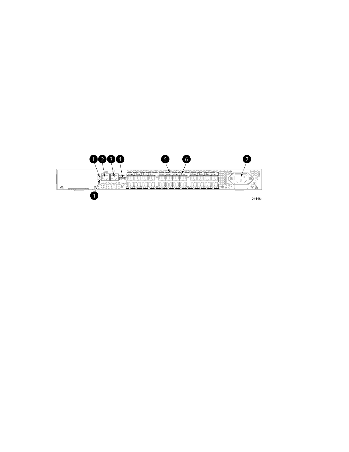
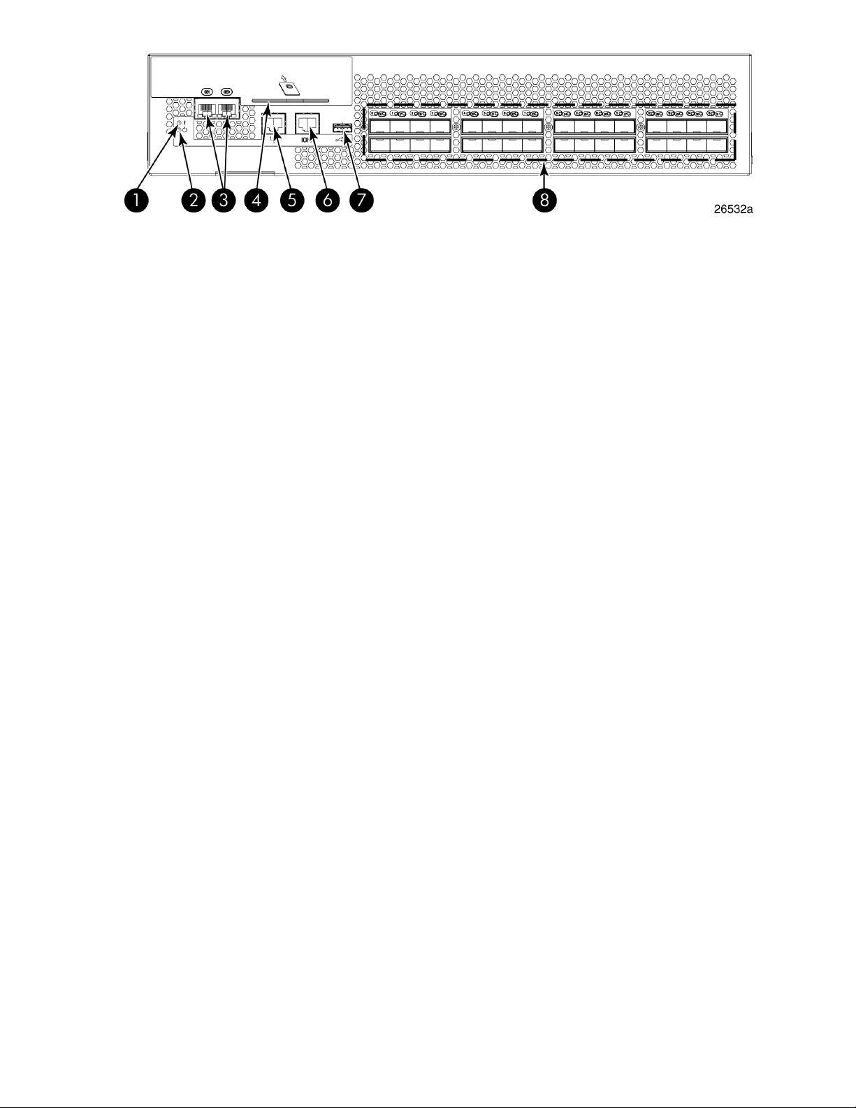
Port side of the 8/8 and 8/24 SAN Switch
The port side of the 8/8 and 8/24 SAN Switch includes the system status LED, console port, Ethernet
port, USB port, and FC ports with corresponding port status LEDs. Additionally, a pull-out tab identifies
the serial number, MAC address, and WWN. Record the switch IP address on the pull-out tab for
easy access.
Figure 1 shows the port side of the 8/8 and 8/24 SAN Switch.
5. Fibre Channel status LEDs1. System status (top) and power (bottom) LEDs
6. Fibre Channel ports (24)2. System RS-232 console port (RJ-45)
7. AC power inlet3. Ethernet port with two Ethernet status LEDs
4. USB port
Figure 1 Port side view—8/8 and 8/24 SAN Switch
.
Nonport side of the 8/8 and 8/24 SAN Switch
The nonport side is used solely for airflow. The enclosure uses forced-air cooling, with the fans pushing
the air from the nonport side of the chassis through the enclosure, and exhausting to the port side.
Activating additional 8/8 and 8/24 SAN Switch ports
By default, the 8/8 SAN Switch model integrates eight licensed ports (ports 0 through 7). Additionally,
the 8/24 SAN Switch model integrates 16 licensed ports (ports 0 through 15). To enable additional
ports, you must purchase and install the HP Storage Works 8/8 and 8/24 SAN Switch 8-Gb 8-port
Upgrade LTU (part number T5518A):
• For the 8/8 SAN Switch—To enable ports 8 through 15, you must purchase and install one upgrade
license. To enable ports 15 through 23, you must purchase and install one upgrade license.
• For the 8/24 SAN Switch—To enable ports 15 through 23, you must purchase and install a
second upgrade license.
8-Gb SAN Switch Hardware Reference Guide 13
Page 14

See Installing and activating Port Upgrade licenses, page 25.
Enabling E_Ports on the 8/8 SAN Switch
The 8/8 SAN Switch model requires that you purchase the HP StorageWorks Full Fabric Upgrade
License (part number T4261A) to enable E_Ports (the 8/24 SAN Switch ships with the Full Fabric
license installed).
By default, the 8/8 SAN Switch cannot be connected to another switch until this license is installed.
Without the license, the switch can still be connected directly to hosts and storage devices. To install
the Full Fabric Upgrade License, use the licenseadd command. When installed, the license appears
under the licenseshow command as Full Fabric License and indicates that E_Ports are now
enabled automatically.
8/40 SAN Switch features
• Provides the EZSwitch Setup Wizard for easy setup and basic configuration.
• Support for 1, 2, 4, and 8 Gb/s autosensing FC switch and router ports.
• Integrates a single motherboard design with 667 MHz PowerPC 440EPx RISC CPU and integrated
peripherals which provide high performance.
• Ships FICON and FICON Cascading ready. FICON CUP is available, but requires an optional
license.
• Provides two hot-swappable, redundant integrated power supply and fan FRUs.
• Universal ports that self-configure as E_Ports, F_Ports, M_Ports, or FL_Ports. EX_Ports are activated
on a per-port basis with the optional HP B-series 48-80 Port SAN Switch Integrated Routing LTU.
This license provides native FCR on a per-port basis, rather than limiting routing ports to those on
a dedicated routing blade or switch. Just like traditional FCR, IR uses EX_Ports to import and export
devices between fabrics, enabling selective device sharing while maintaining remote fabric isolation.
• Integrates a USB port that provides storage for firmware updates, output of the supportsave
command and storage for configuration uploads and downloads.
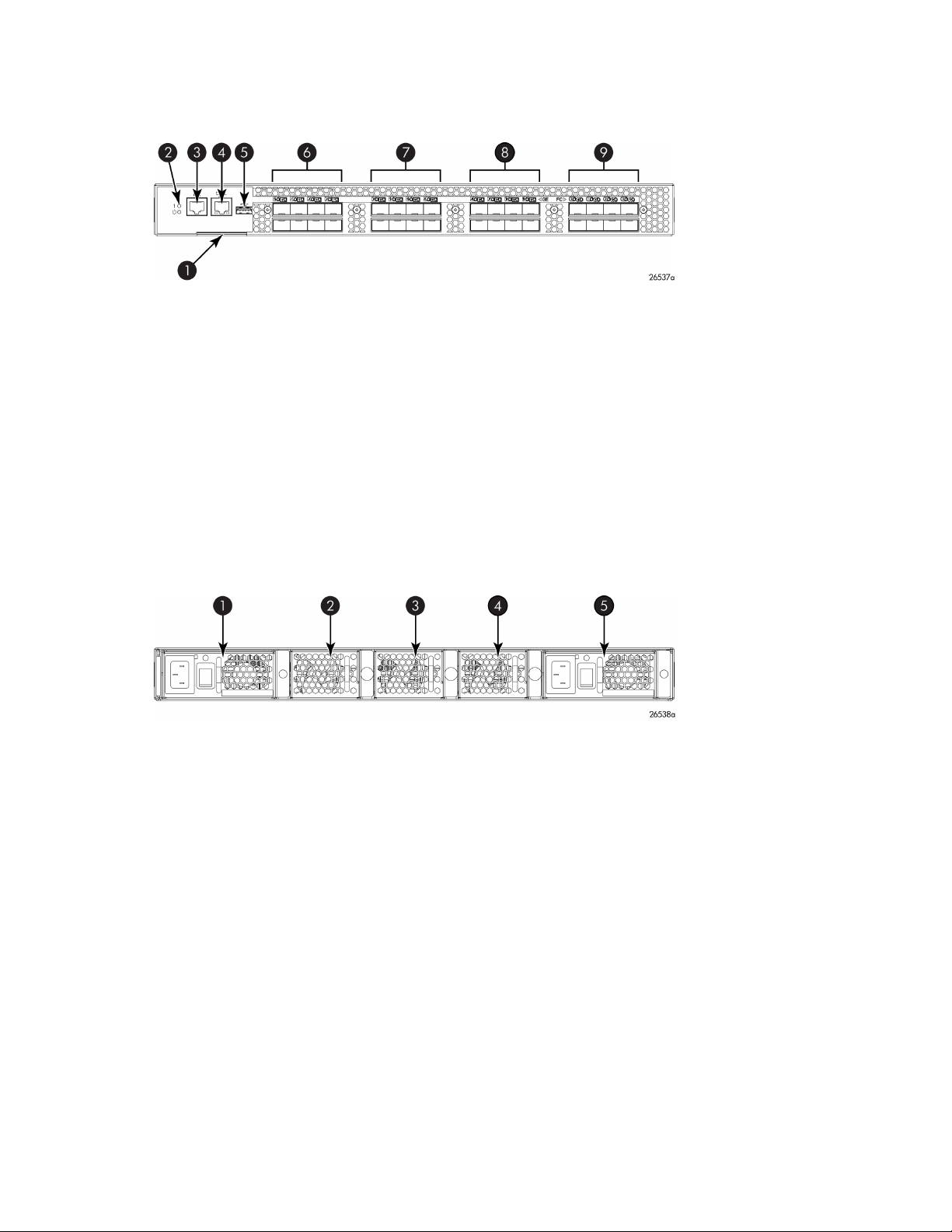
Port side of the 8/40 SAN Switch
The port side of the 8/40 SAN Switch includes the system status LED, console port, Ethernet port and
LEDs, USB port, and FC ports with corresponding port status LEDs.
Figure 2 shows the port side of the 8/40 SAN Switch.
HP StorageWorks 8-Gb SAN Switches14
Page 15
4. Ethernet port LEDs (green/amber)
Figure 2 Port side view—8/40 SAN Switch
.
Nonport side of the 8/40 SAN Switch
The nonport side includes the two redundant power supply fan assemblies and the corresponding
status LEDs. Figure 3 shows the nonport side of the 8/40 SAN Switch.
5. USB port1. System status (top) and power (bottom) LEDs
6. Fibre Channel port status LED2. System RS-232 console port (RJ-45)
7. Fibre Channel port3. System Ethernet port
5. Fan (for power supply/fan FRU1)1. Fan (for power supply/fan FRU2)
2. Power supply/fan status LED (for power supply/fan
FRU2)
3. Power supply connector (for power supply/fan
FRU2)
Figure 3 Nonport side view—8/40 SAN Switch
.
Activating additional 8/40 SAN Switch ports
By default, the 8/40 SAN Switch model integrates 24 licensed ports (ports 0 through 23). To enable
additional ports, you must purchase and install the HP Storage Works 8/40 SAN Switch 8-Gb 8-port
Upgrade LTU (part number T5519A):
8-Gb SAN Switch Hardware Reference Guide 15
6. Power supply/fan status LED (for power supply/fan
FRU 1)
7. Power supply connector (for power supply/fan FRU
1)
8. Fan (for power supply/fan FRU1)4. Fan (for power supply/fan FRU2)
Page 16

• To enable ports 24 through 31, you must purchase and install one upgrade license.
• To enable ports 32 through 40, you must purchase and install a second upgrade license.
See Installing and activating Port Upgrade licenses, page 25.
8/80 SAN Switch features
• Provides the EZSwitch Setup Wizard for easy setup and basic configuration.
• Integrates 1, 2, 4, and 8 Gb/s autosensing Fibre Channel switch and router ports.
• Includes a system motherboard that features a Freescale MPC8548 RISC CPU running at 1.3 GHz
with integrated peripherals that provides high performance with low power consumption.
• Ships FICON and FICON Cascading ready. FICON CUP is available, but requires an optional
license.
• Provides two hot-swappable, redundant power supply FRUs.
• Provides three hot-swappable fan FRUs in an N+1 configuration to provide hardware-redundant
cooling.
• Provides universal ports that self-configure as E_Ports, F_Ports, M_Ports, or FL_Ports. EX_Ports are
activated on a per-port basis with the optional HP B-series 48-80 Port SAN Switch Integrated
Routing LTU.
This license provides native FCR on a per-port basis, rather than limiting routing ports to those on
a dedicated routing blade or switch. Just like traditional FCR, Integrated Routing uses EX_Ports to
import and export devices between fabrics, enabling selective device sharing while maintaining
remote fabric isolation.
• Integrates a USB port that provides storage for firmware updates, output of the supportsave
command, and storage for configuration uploads and downloads.
Port side of the 8/80 SAN Switch
The port side of the 8/80 SAN Switch includes the system status LED, console port, Ethernet port and
LEDs, USB port, and FC ports with corresponding port status LEDs. Figure 4 shows the port side of
the 8/80 SAN Switch.
HP StorageWorks 8-Gb SAN Switches16
Page 17
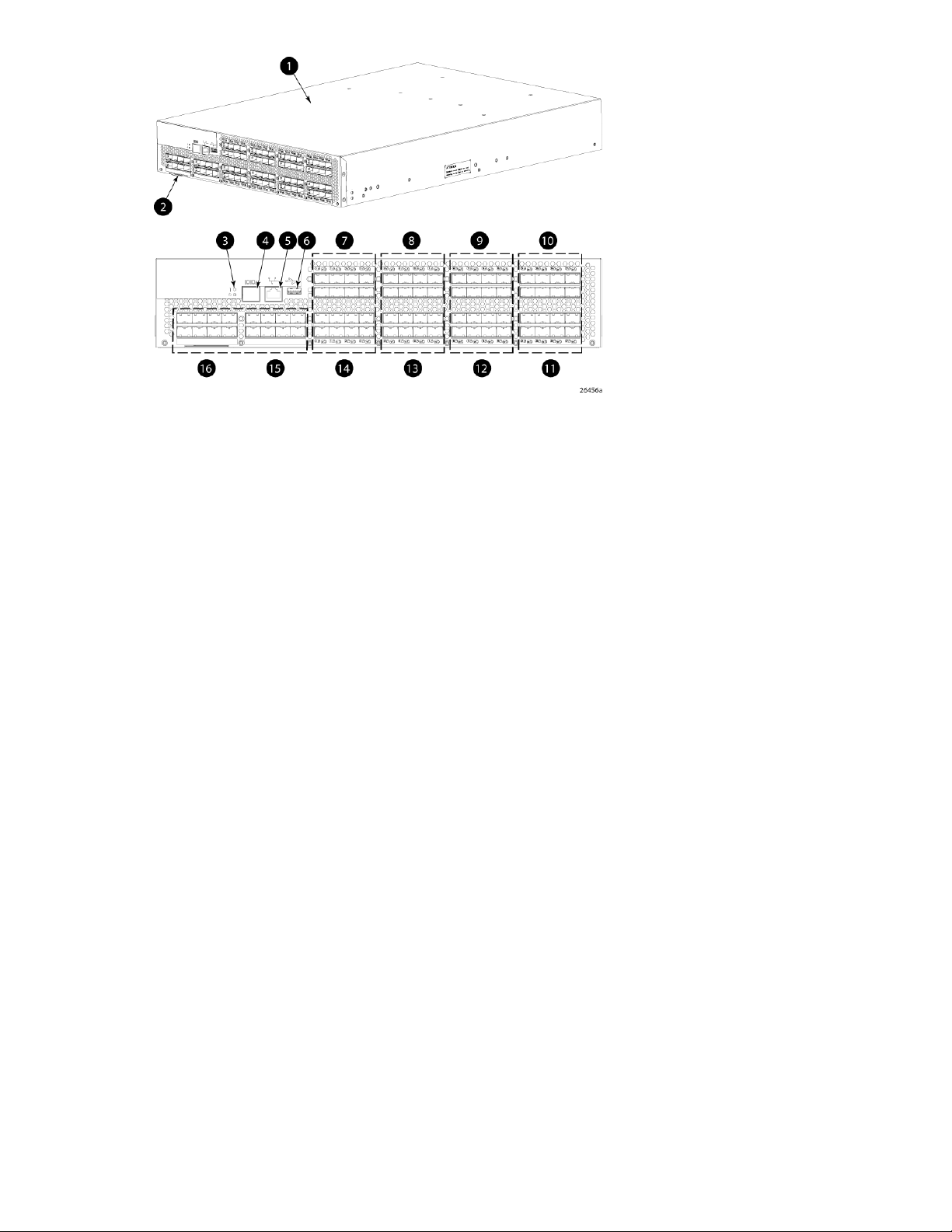
9. FC ports 16–231. 8/80 SAN Switch
10. FC ports 24–312. Switch ID pull-out tab
11. FC ports 32–383. Status LED (top) power LED (bottom)
12. FC ports 40–474. Console port
13. FC ports 48–555. Ethernet port
14. FC ports 56–636. USB port
15. FC ports 64–717. FC ports 0–7
16. FC ports 72–798. FC ports 8–15
Figure 4 Port side view—8/80 SAN Switch
.
Nonport side of the 8/80 SAN Switch and the Encryption SAN Switch
Figure 5 shows the nonport side of the 8/80 SAN Switch and the Encryption SAN Switch, which
contains the power supplies (including the AC power receptacle and AC power switch) and fans.
8-Gb SAN Switch Hardware Reference Guide 17
Page 18
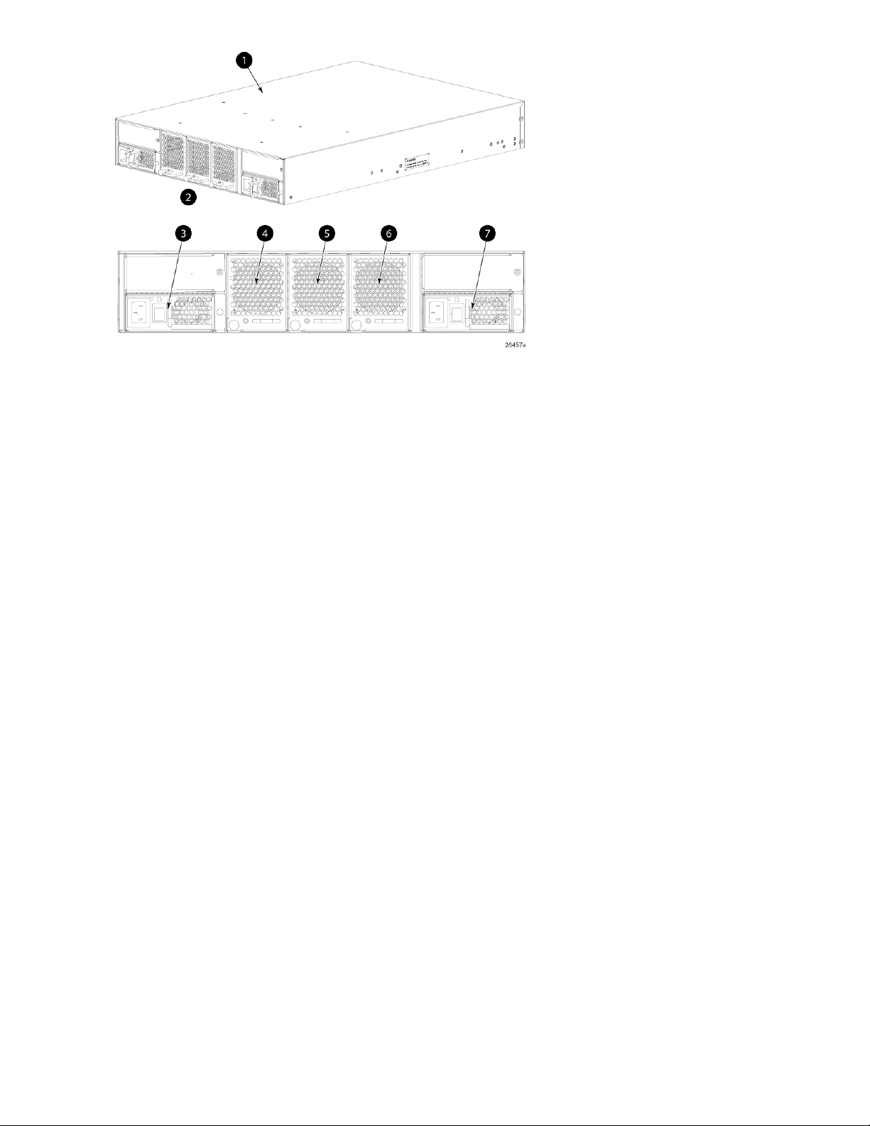
4. Fan assembly #3
Figure 5 Nonport side view—8/80 SAN Switch
.
Activating additional 8/80 SAN Switch ports
By default, the 8/80 SAN Switch model integrates 48 licensed ports (ports 0 through 47). To enable
additional ports, you must purchase and install the HP StorageWorks 8/80 SAN Switch 8-Gb 16-port
Upgrade LTU (part number T5520A):
• To enable ports 48 through 63, you must purchase and install one upgrade license.
• To enable ports 64 through 80, you must purchase and install a second upgrade license.
See Installing and activating Port Upgrade licenses, page 25.
Encryption SAN Switch features
The Encryption SAN Switch has the following features:
5. Fan assembly #21. 8/80 SAN Switch
6. Fan assembly #12. Nonport side
7. Power supply #13. Power supply #2
• 32 front-end 1, 2, 4, or 8 Gb/s autosensing F_Port, FL_Port, E_Port, EX_Port, or M_Ports to connect
host servers, SAN disks, SAN tapes, edge switches, or core switches
• Encryption and decryption engines to provide in-line crypto services with up to 96 Gb/s throughput
for disk I/O and up to 48 Gb/s throughput for tape I/O (mix of ciphertext and cleartext traffic)
• Integrated with HP SKM system
• Full 1:1 subscription on all 32 ports at 8 Gb/s
• HA cluster, DEK cluster, and EG to enable transparent failover, host MPIO failover, and centralized
management of multiple encryption switches
• Support for automatic expiry or CLI manual based re-keying
HP StorageWorks 8-Gb SAN Switches18
Page 19

• Compliance with encryption standards: AES256-XTS 1619.1 (for disk); AES256-GCM IEEE 1619.2
(for tape)
• Smart Card
• Hardware-based key management and generation
• IR Fabric Service (optional) to enable encryption capabilities across multiple fabrics
• NPIV support
• Two hot-swappable, redundant power supply FRUs
• Three hot-swappable fan FRUs in the N+1 configuration to provide hardware-redundant cooling
• One RJ-45 10/100/1000 Ethernet management port
• Two RJ-45 GE ports for clustering interconnection and re-key, and DEK synchronization within
cluster
• One RJ-45 serial console port
• A USB port that facilitates firmware upgrades, serviceability, and system-log functionality
• A switch subsystem and encryption subsystem that features a CPU running at 1.3 GHz with integ-
rated peripherals that provide high performance with low power consumption
• DPS, optimizing fabric-wide performance and load balancing by automatically routing data to
the most efficient available path in the fabric
• SFP or SFP+ optical transceivers, providing support for a combination of SWL, LWL, or ELWL op-
tical media among the switch ports
NOTE:
The full range of 1, 2, 4, and 8 Gb/s can be achieved only by a combination of 4 Gb/s SFPs (1,
2, and 4 Gb/s) and 8 Gb/s SFP+ (2, 4, and 8 Gb/s).
• Fabric OS support, delivering distributed intelligence throughout the network and enabling a wide
range of applications including Web Tools and Zoning. Optional fabric services include: Adaptive
Networking with QoS, Extended Fabrics, Enhanced Group Management, Fabric Watch, ISL
Trunking, IR, and End-to-End performance monitoring using APM.
• Extensive diagnostics and system-monitoring capabilities to enhance high RAS
• Pay as you go port and performance scalability through an Encryption Performance Upgrade Li-
cense. The base configuration provides 48 Gb/s of encryption bandwidth. The Encryption Per-
formance Upgrade License activates an additional 48 Gb/s bandwidth. Each switch accepts two
encryption-performance upgrades for a total of 96 Gb/s of encryption bandwidth. The front-end
user ports in the basic, first, and second levels of encryption bandwidth remain as 32 ports at 8
Gb/s Fibre Channel.
Port side of the Encryption SAN Switch
The port side of the Encryption SAN Switch includes the status and power LEDs, smart card reader,
the RJ-45 USB, and FC ports. Figure 6 shows the port side of the Encryption SAN Switch.
8-Gb SAN Switch Hardware Reference Guide 19
Page 20
5. RJ-45 management port1. Status LED
6. RJ-45 serial console port2. Power LED
7. USB port3. RJ-45 GE ports (for clustering and re-keying)
8. Fibre Channel ports (0–31)4. Smart Card reader
Figure 6 Port side of the Encryption SAN Switch
.
FCoE Converged Network Switch features
The FCoE Converged Network Switch has the following features:
• Includes a system motherboard with a Freescale MPC8548 RISC CPU running at 1.3 GHz and
integrated peripherals, that provides high performance with low power consumption
• Contains an RJ-45 Ethernet management port and EZSwitch Setup, which supports switch IP address
discovery and configuration
• Integrates a USB port that provides storage for firmware updates, as well as supportsave
command output and configuration uploads and downloads
• Provides two hot-swappable, redundant power supply FRUs
• Provides three hot-swappable fan FRUs in an N+1 configuration to provide hardware-redundant
cooling
• Includes universal ports that self-configure as E_Ports, F_Ports, M_Ports, or FL_Ports
• Provides extensive diagnostics and system-monitoring capabilities for enhanced RAS
• Provides FCoE-to-FC latency of 1,670 ns
The FCoE Converged Network Switch has the following Ethernet capabilities:
• Contains 24 ports, 10-GbE CEE
• Provides low-latency, lossless, deterministic interconnect required for FCoE
• Provides FCoE support with FPMA discovery. Fabric OS also enables support for Priority-based
Flow Control (802.1Qbb)
• Includes DCBX - Capabilities Exchange and Enhanced Transmission Selection (802.1Qaz) to meet
the lossless and deterministic FCoE requirement
• Enables hardware-assisted MAC learning and aging
• Support for 32,768 MAC addresses and 4,096 VLANs
• Support for Layer 2 protocols STP/MSTP/RSTP (802.1q) and Link Aggregation (802.1ad)
• HP branded 10-Gb SFP+ (SR and LR) and active copper cables
• Provides CEE port to CEE port latency of 570 ns (same ASIC) and 1,050 ns (different ASIC)
HP StorageWorks 8-Gb SAN Switches20
Page 21
Port side of the FCoE Converged Network Switch
Figure 7 shows the port side of the FCoE Converged Network Switch.
6. 10-GbE ports 0–71. Switch ID pull-out tab
7. 10-GbE ports 8–152. System status (top) and power (bottom) LEDs
8. 10-GbE ports 16–233. Serial console port
9. FC ports 0–74. Management Ethernet port
5. USB port
Figure 7 Port side of the FCoE Converged Network Switch
.
Nonport side of the FCoE Converged Network Switch
Figure 8 shows the nonport side of the FCoE Converged Network Switch.
4. Fan assembly #11. Power supply #2
5. Power supply #12. Fan assembly #3
3. Fan assembly #2
Figure 8 Nonport side of the FCoE Converged Network Switch
.
1606 Extension SAN Switch features
A fully licensed 1606 Extension SAN Switch has the following features:
• FCIP capability
• Includes up to eight FCIP tunnels.
• Each FCIP tunnel is represented and managed as a VE_Port.
• Fibre Channel Routing Services can be used over the FCIP link.
8-Gb SAN Switch Hardware Reference Guide 21
Page 22

• Fabrics connected through FCIP merge if the ports are configured as VE_Ports, and do not
merge if one end of the connection is configured as a VEx_Port. If VE_Ports are used in a Fibre
Channel Routing Services backbone fabric configuration, then the backbone fabric merges
but the EX_Ports attached to edge fabrics do not merge. For more information, see the Fabric
OS Administrator’s Guide.
• FCIP Trunking with load balancing and network-based failure recovery
• Adaptive Rate Limiting
• Configurable minimum and maximum committed bandwidth per FCIP tunnel
• Minimum rate is guaranteed rate
• FC Frame Compression before FCIP Encapsulation
• FCR
• SOTCP with reorder resistance
• FastWrite over FCIP (not over FC)
• Open Systems Tape Pipelining over FCIP
• FCIP QoS
• TCP Performance Graphing in Web Tools
• FICON and FICON Cascading ready.
• FICON CUP (requires an optional license).
• FICON Accelerator for IBM TotalStorage z/OS Global Mirror (aka, XRC) and FICON Tape (requires
an optional license).
The 1606 Extension SAN Switch has the following hardware features:
• Up to 16 Fibre Channel SFP ports supporting Fibre Channel Switching or Fibre Channel Routing
Services, with link speeds of 1-, 2-, 4-, or 8-Gb/s
• Up to 6 1-GbE ports supporting the FCIP and Fibre Channel Routing Services features, with
transmit link speeds of up to 1-Gb/s on each port
Two ports (ge0 and ge1) can be configured for use with either copper or optical cables
• Rack–mountable 1U chassis
• Two PowerPC 440EPx processors running at 667 MHz
• One GoldenEye2 switch ASIC for 1, 2, 4, or 8 Gb/s FC switching
• One Cavium CN5740 running with 8 MIPS cores at 750 MHz for data path processing
• One Blaster FPGA for FC compression, offloads such as chksum generation/checks
• One 10/100/1000 Base-T Ethernet port for the management interface
• One RJ-45 terminal port
• One USB port for storing firmware updates, supportSave command output, and configuration
uploads and downloads
• Two redundant, hot-swappable combined power supply/fan assembly FRUs
• Five internal temperature sensors
HP StorageWorks 8-Gb SAN Switches22
Page 23

Feature comparison of base and upgraded products
Table 1 compares the features supported on the base and fully upgraded 1606 Extension SAN Switch.
It also lists the optionally licensed features.
Table 1 Comparison of 1606 Extension SAN Switch features
With upgrade licenseBase productFeature
164Number of Fibre Channel ports
62Number of GbE ports
Fibre Channel Routing between remote fabrics for fault isolation
FCIP Trunking
Adaptive Rate Limiting
Open Systems Tape Pipelining over
FCIP Tunnel
1
Requires Integrated Routing license
2
Requires Advanced Extension license
Yes
Yes
Yes
1
2
2
Yes
YesYesFCIP Tunnel
82Number of FCIP tunnels
Yes
Yes
YesYesFC Frame Compression
YesYesSOTCP
YesYesFastWrite over FCIP Tunnel
YesNo
1
2
2
• Before installation of the upgrade license, any ports other than the basic four FC ports and two
GbE ports are shown as Disabled when you execute the switchshow command.
• On the base 1606 Extension SAN Switch, you can configure the two GbE ports (ge0 and ge1)
for use with either copper or optical cables (physically separate ports are provided).
• FC frame compression is not the same as IP compression and is disabled by default. To enable
FC frame compression use the portCfg command. For more information, see the Fabric OS
Administrator’s Guide.
• FCIP tunnel bandwidth has a minimum rate of 1,544 Kb/s (the T1 rate). Configuration requests
with lower rates are rejected.
• FCIP Trunking is available to virtualize two or more IP address pairs (circuits) as part of a single
FCIP tunnel. You can configure up to four circuits for a single FCIP tunnel. For more information
on configuring circuits, see the Fabric OS Administrator’s Guide.
• Multiple FCIP tunnels can share the same GbE port. VE_Ports and VEx_Ports are not associated
with a single physical GbE port.
Available licenses
The following features are available with the purchase of a license key for the 1606 Extension SAN
Switch:
• Advanced Extension
8-Gb SAN Switch Hardware Reference Guide 23
Page 24
• IR
• Extended Fabric
• Adaptive Networking
• Server Application Optimization
• ISL Trunking
• Fabric Watch
• Advanced Performance Monitor
• FICON CUP
• FICON Accelerator
For information on these features, see the Fabric OS Administrator’s Guide.
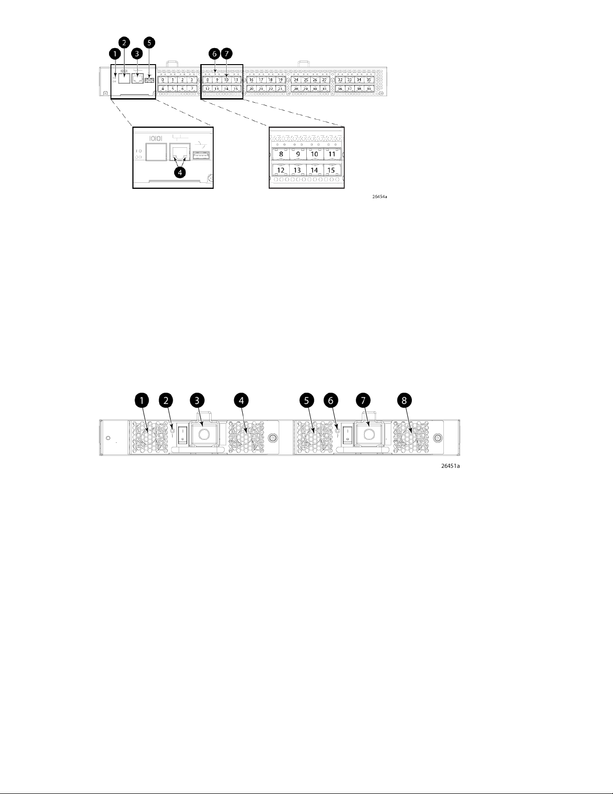
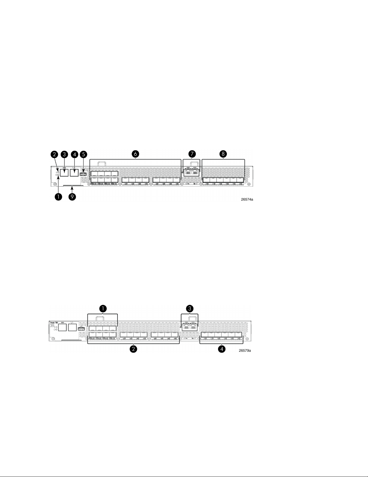
Port side of the 1606 Extension SAN Switch
Figure 9 shows the components on the port side of the 1606 Extension SAN Switch.
6. Fibre Channel ports (16)1. System power LED
7. GbE ports: copper RJ45(2)2. System status LED
8. GbE ports: optical SFP (6)3. Console port (RJ45)
9. Serial number pull-out tab4. Ethernet management port
5. USB port
Figure 9 Port side of the HP 1606 Extension SAN Switch
.
The Fibre Channel ports are numbered from left to right on the faceplate, as shown in Figure 10.
3. GbE ports: ge0-ge1 (copper only)1. Fibre Channel ports 0–3
4. GbE ports: ge0–ge5 (SFP)2. Fibre Channel ports 4–15
Figure 10 Port numbering on the 1606 Extension SAN Switch
.
A fully licensed 1606 Extension SAN Switch can have two trunking groups. Group 1 consists of Fibre
Channel ports 0–7, and group 2 consists of Fibre Channel ports 8–15.
HP StorageWorks 8-Gb SAN Switches24
Page 25
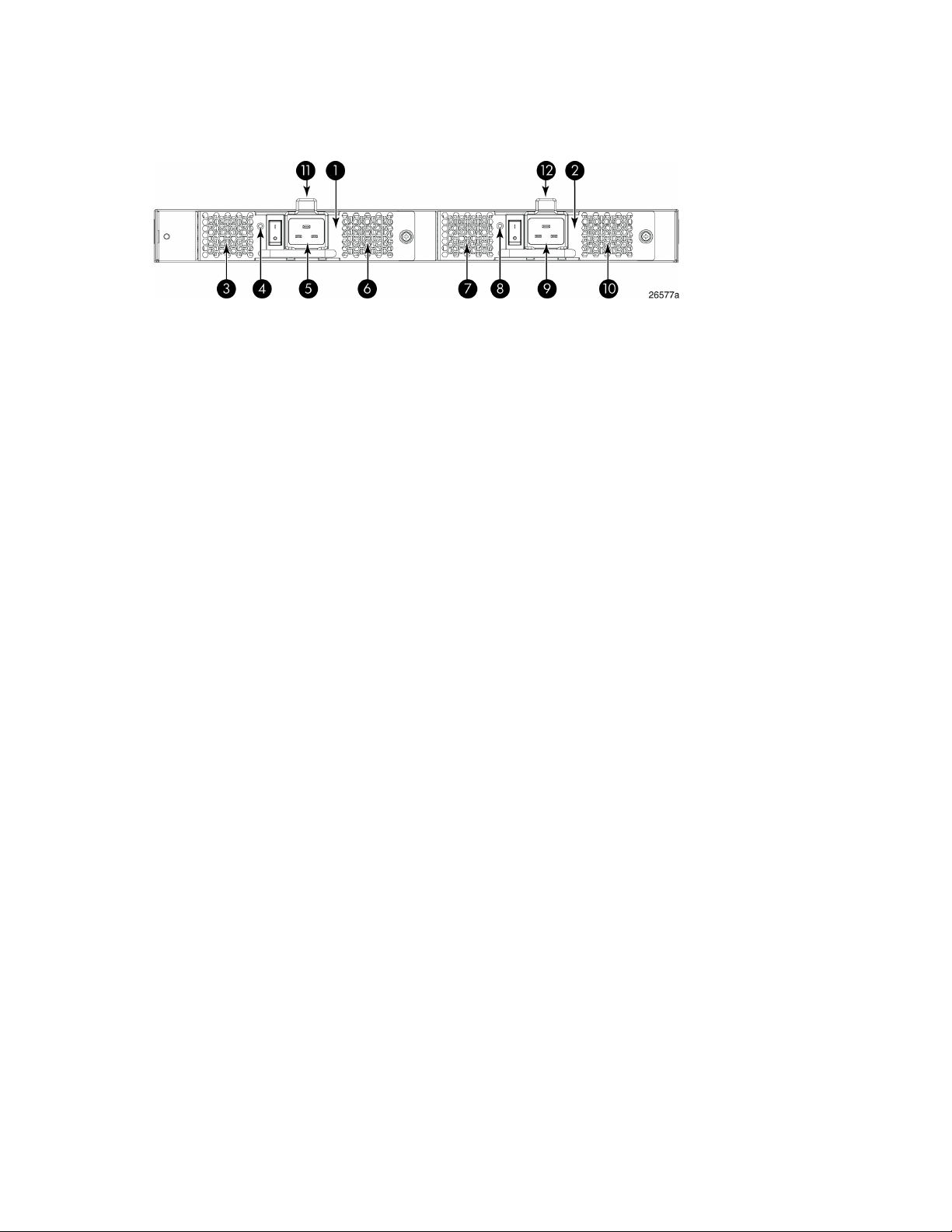
Nonport side of the 1606 Extension SAN Switch
Figure 11 shows the nonport side of the 1606 Extension SAN Switch, which contains the combined
power supplies and fans.
7. Fan assembly 11. Fan and power supply assembly #2
8. FRU LED2. Fan and power supply assembly #1
9. Power supply #13. Fan assembly #2
10. Fan assembly #14. FRU LED
11. FRU handle5. Power supply #2
12. FRU handle6. Fan assembly #2
Figure 11 Nonport side of the 1606 Extension SAN Switch
.
Installing and activating Port Upgrade licenses
1. Use the portshow command to verify the number of ports licensed on your switch. The port
status output indicates Started and Licensed for enabled ports. For more information on this
command, see the Fabric OS Command Reference Manual.
2. Obtain the WWN from the Switch ID pull-out tab located on the port side of your switch.
Alternately, you can use the switchshow command to display the WWN.
3. Contact your HP representative to purchase the appropriate Port Upgrade license. HP requires
the switch WWN obtained in Step 2 to assign a license key.
8-Gb SAN Switch Hardware Reference Guide 25
Page 26

4. Install the license:
a. Log in to the switch as admin.
b. Issue the licenseadd command, followed by the license key enclosed in quotation marks.
(The license key consists of approximately 16 uppercase and lowercase letters and numerals.)
IMPORTANT:
Enter the license key exactly as issued. If you enter the key incorrectly, the license will
not function properly.
c. Enter the licenseshow command to verify that the license is valid. If a licensed product is
not displayed, the license is not valid.
NOTE:
It is not necessary to reboot the system.
5. Configure the inactive ports. Enter the portstart command to start the ports. This command
loads the port code, unlike the portenable command, which enables the port laser. For example:
portstart 16–31
6. Enter the portenable command to enable the ports. For example:
portenable 16–31
7. Optional: Enter the portshow command to verify that the newly activated ports are started.
SAN Switch ISL Trunking groups
All 8-Gb SAN Switch models support ISL Trunking as an optional, licensed feature for FC ports. When
this feature is enabled, trunked groups of up to eight contiguous ports are created.
For example, the Fibre Channel ports on the SAN Switch are numbered from left to right and
color-coded into groups of eight to indicate which ports you can combine into trunked groups. Figure
12 shows the 8/8 SAN Switch with three trunked groups of eight ports.
NOTE:
If your 8-Gb SAN Switch is licensed for ISL Trunking (for example, Power Pack+ models ship with
this license), use the trunking groups available on the switch.
HP StorageWorks 8-Gb SAN Switches26
Page 27
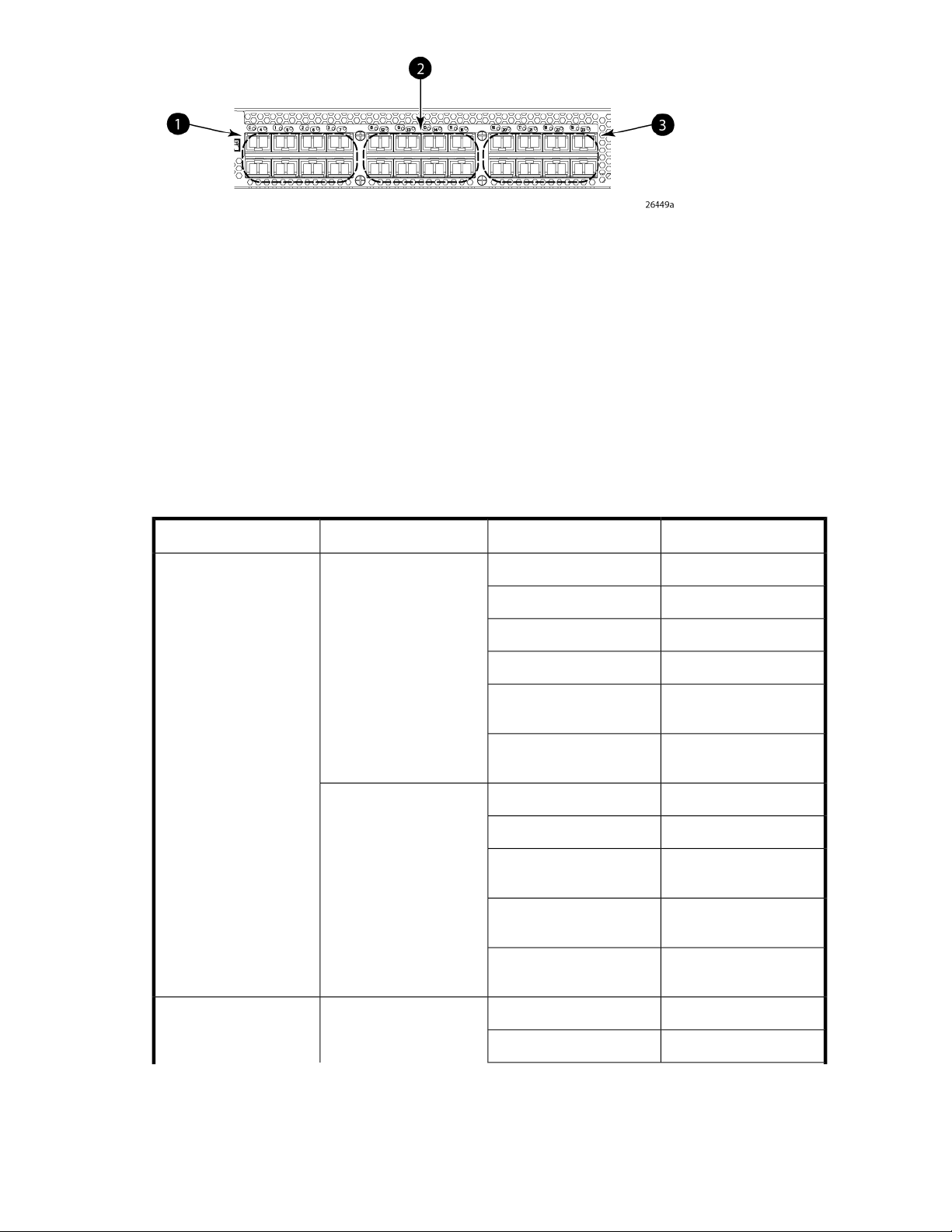
2. Trunk group 2: Ports 8–15
Figure 12 Trunking groups example
.
For more information about trunking, see the Fabric OS Administrator's Guide for the firmware version
you are running.
Supported SFP transceiver options
Table 2 lists the only SFPs supported in your HP StorageWorks 8-Gb SAN Switches.
Table 2 Supported SFP transceiver options
3. Trunk group 3: Ports 16–231. Trunk group 1: Ports 0–7
Part numberOptionPort typeSwitch product
AJ716A8Gb/s short wave SFP+
AJ717A8Gb/s long wave SFP+
AJ715A4Gb/s short wave SFP
2408 FCoE switch
Fibre Channel
10GbE CEE ports
Fibre Channel1606 Extension switch
4Gb/s extended long
wave SFP
8Gb/s extended long
wave SFP
1m active copper SFP+
cable
3m active copper SFP+
cable
5m active copper SFP+
cable
AK870A4Gb/s long wave SFP
AN211A
AW538A
AP823A10GbE short range SFP+
AP824A10GbE long range SFP+
AP818A
AP819A
AP820A
AJ716A8Gb/s short-wave SFP+
AJ717A8Gb/s long-wave SFP+
8-Gb SAN Switch Hardware Reference Guide 27
Page 28

Part numberOptionPort typeSwitch product
AJ715A4Gb/s short-wave SFP
AK870A4Gb/s long-wave SFP
1GbE FCIP ports
Fibre Channel8Gb SAN Switches
4Gb/s extended longwave SFP
8Gb/s extended longwave SFP
4Gb/s extended longwave SFP
4Gb/s extended longwave SFP
8Gb/s extended longwave SFP
AN211A
AW538A
AJ715A4Gb/s short-wave SFP
AK870A4Gb/s long-wave SFP
AN211A
AW537A1GbE copper SFP
AJ716A8Gb/s short-wave SFP+
AJ717A8Gb/s long-wave SFP+
AJ715A4Gb/s short-wave SFP
AK870A4Gb/s long-wave SFP
AN211A
AW538A
8-Gb SAN Switch software options
The following optional software kits and licenses are available. More information on these products
is include in the product QuickSpecs, which can be accessed from the HP website:
http://h18006.www1.hp.com/storage/networking/b_switches/san/index.html
• HP StorageWorks Full Fabric Upgrade License
• HP StorageWorks 8/8 and 8/24 SAN Switch 8-Gb 8-port Upgrade LTU
• HP StorageWorks 8/80 SAN Switch 8-Gb 16-port Upgrade LTU
• HP StorageWorks 8/40 SAN Switch 8-Gb 8-port Upgrade LTU
• Adaptive Networking
• Fabric Watch
• ISL Trunking
• APM
• Extended Fabric
• HP B-series 48-80 Port SAN Switch Integrated Routing LTU (purchase for 8/80 SAN Switch only)
• Data Center Fabric Manager Professional Plus (4 fabrics, 2560 switch ports)
• Data Center Fabric Manager Enterprise (24 fabrics, 9000 switch ports)
• HP Encryption SAN Switch Performance Upgrade LTU
HP StorageWorks 8-Gb SAN Switches28
Page 29

• HP StorageWorks 1606 Switch Upgrade to Full LTU
• HP StorageWorks Extension SAN Switch Advanced LTU
• HP StorageWorks 1606 Extension SAN Switch FICON Control Unit Port LTU
• HP StorageWorks 1606 Extension SAN Switch Integrated Routing LTU (purchase for 1606 Extension
SAN Switch only)
• HP 1606 Switch FICON CUP Accelerator LTU
• HP StorageWorks Power Pack Upgrade
• SAO
• HP B-series 24-40 Port SAN Switch Integrated Routing LTU (purchase for 8/40 SAN Switch only)
8-Gb SAN Switch hardware options
Table 3 lists the optional hardware kits.
Table 3 Optional hardware kits
OM2 LC-LC type cables
Order numberHardware kit
AK864AHP StorageWorks 2-Gb USB Device
221692-B212 m LC-to-LC multi-mode FC cable
OM3 LC-LC type cables
LC-SC for between a 1-Gb and a 2-Gb device
221692-B225 m LC-to-LC multi-mode FC cable
221692-B2315 m LC-to-LC multi-mode FC cable
221692-B2630 m LC-to-LC multi-mode FC cable
221692-B2750 m LC-to-LC multi-mode FC cable
AJ833A0.5 m LC-LC multi-mode OM3 FC cable
AJ834A1 m LC-LC multi-mode OM3 FC cable
AJ835A2 m LC-LC multi-mode OM3 FC cable
AJ836A5 m LC-LC multi-mode OM3 FC cable
AJ837A15 m LC-LC multi-mode OM3 FC cable
AJ838A30 m LC-LC multi-mode OM3 FC cable
AJ839A50 m LC-LC multi-mode OM3 FC cable
221691-B212 m LC-SC multi-mode FC cable
221691-B225 m LC-SC multi-mode FC cable
221691-B2315 m LC-SC multi-mode FC cable
221691-B2630 m LC-SC multi-mode FC cable
8-Gb SAN Switch Hardware Reference Guide 29
Page 30

Order numberHardware kit
221691-B2750 m LC-SC multi-mode FC cable
NOTE:
For the latest information on hardware and software components, see the B-series Switches section
of the HP Storage Networking website: http://www.hp.com/go/san.
HP StorageWorks 8-Gb SAN Switches30
Page 31

2 Installing and configuring an 8-Gb SAN Switch
This chapter provides information about and instructions to install and configure an 8-Gb SAN Switch.
Shipping carton contents
Figure 13 and Table 4 identify shipping carton contents for a typical 8-Gb SAN Switch. The shipping
configuration for your model can vary.
1. Accessory kit
2. Rails
3. Switch
Figure 13 8/40 SAN Switch shipping carton contents
.
8-Gb SAN Switch Hardware Reference Guide 31
Page 32

Table 4 8-Gb SAN Switch shipping carton contents
Description
One accessory kit, containing the following items:
• HP StorageWorks product documentation:
• HP StorageWorks 8-Gb SAN Switch Quick Start Instructions
• HP StorageWorks SAN Switch Rack Mount Kit Installation Instructions
• Read Me First
• Safety Guides
• User License
• Warranty
• A serial cable, approximately 3 m (10 ft.)
• Plenum (not shown) ships in your switch accessory kit only if required for installing your switch in an HP
custom rack. For more information, see the HP StorageWorks SAN Switch Rack Mount Kit Installation Instructions. The plenum is an air duct that attaches to the SAN Switch Rack Mount Kit switch rails.
• Four rubber feet for mounting on a flat surface (a lab bench, for example)
• EZSwitch Setup CD
• One or two grounded power cords, as required for your particular switch
• PDU power cords, as required for your particular switch
SAN Switch Rack Mount Kit hardware and rail assemblies:
• Two rear mounting brackets
• A right inner rail and a right outer rail
• A left inner rail and a left outer rail
One 8-Gb SAN Switch, including power supply and fan assembly units
Installation and safety considerations
You can install the switch in a rack or as a standalone device on a flat surface.
HP highly recommends mounting the switch in one of the following HP customized racks:
• HP System/e Rack
• HP 10000 G2 Series Rack and HP 10000 Series Rack
Electrical considerations
For successful installation and operation of the switch, ensure that the following electrical requirements
are met:
• The primary outlet is correctly wired, protected by a circuit breaker, and grounded in accordance
with local electrical codes.
• The supply circuit, line fusing, and wire size are adequate, as specified by the electrical rating
on the switch nameplate.
• A minimum of 79.8 cubic meters/hour (47 cubic feet/minute) of airflow is available to the air intake
vents on the nonport side of the switch.
• The power supply standards provided in “Power supply specifications” on page 88, are met.
Installing and configuring an 8-Gb SAN Switch32
Page 33

Environmental considerations
Before installing the switch, verify that the following environmental requirements are met:
• Install the switch with the nonport side, which contains the air intake vents, facing the cool-air
aisle.
• All equipment in the rack forces air in the same direction, to avoid taking in exhaust air.
• A minimum of 24 cubic ft/min of airflow is available to the air intake vents on the nonport side
of the switch.
• The ambient air temperature does not exceed 40°C (104°F) while the switch is operating.
IMPORTANT:
The 40ºC value applies to the ambient air temperature at the air intake vents on the nonport side of
the switch. The temperature inside the switch can be up to 80ºC (176ºF) during switch operation. If
the internal temperature range exceeds the operating ranges of the components, the LEDs, error
messages, and Fabric Watch alerts indicate a problem. Enter the tempshow or fabric watch
command to view the temperature status.
Rack mount considerations
If you are installing the switch in a rack, verify that the following requirements are met:
• The cabinet or rack must be a standard EIA cabinet.
• Plan rack mount space that is 1 U high, and 48.3 cm (19 inches) wide. One U is 4.45 cm (1.75
inches).
• Ground all equipment in the cabinet through a reliable branch circuit connection, and maintain
ground at all times. Do not rely on a secondary connection to a branch circuit, such as a power
strip.
• Ensure that airflow and temperature requirements are met on an ongoing basis, particularly if the
switch is installed in a closed or multirack assembly.
• Verify that the additional weight of the switch does not exceed the cabinet’s weight limits.
• Secure the rack to ensure stability in case of unexpected movement, such as an earthquake.
Cabling considerations
NOTE:
Cables can be organized and managed in a variety of ways: for example, using cable channels on
the sides of the cabinet or patch panels to minimize cable management.
Before installing the switch, plan for cable management based on the following HP recommendations:
• Leave enough space to allow for the fact that the minimum bend radius for a 50-micron cable is
5 cm (2 inches) under full tensile load and 3 cm (1.2 inches) with no tensile load.
• Leave at least 1 m (3.28 ft) of slack for each port cable. This provides room to remove and replace
the switch, allows for inadvertent movement of the rack, and helps prevent the cables from being
bent to less than the minimum bend radius.
8-Gb SAN Switch Hardware Reference Guide 33
Page 34

• If you are using ISL Trunking, consider grouping cables by trunking groups. The cables used in
trunking groups must meet specific requirements, as described in the Fabric OS Administrator's
Guide.
• For easier maintenance, label the fiber optic cables, and record the devices to which they are
connected.
• Keep LEDs visible by routing port cables and other cables away from the LEDs.
CAUTION:
Do not use tie wraps on fiber optic cables because wraps are easily overtightened and can damage
the optical fibers.
• Use Velcro straps to secure and organize fiber optic cables.
Items required for installation
Obtain the following:
• 8-Gb SAN Switch installed and connected to a power source
• A workstation with an installed terminal emulator, such as HyperTerminal
• Unused IP address and corresponding subnet mask and gateway address
• Serial cable (supplied with switch)
• Ethernet cable
• SFP transceivers and compatible cables, as required
NOTE:
For FCoE Converged Network Switches, both HP-branded FC SFPs and CEE 10-GbE SFPs are
required. FC SFP+ transceivers are required for 8-Gb/s performance; copper cables must be
HP-branded.
• Access to an FTP server to back up the switch configuration (optional)
Installing the switch as a standalone device
To install the switch as a standalone unit:
1. Unpack the switch, and verify that all items listed in “Shipping carton contents” on page 31 are
present.
2. Locate the four rubber feet in the accessory box.
3. Apply the adhesive rubber feet to the switch. The rubber feet help prevent the switch from sliding
off the supporting surface.
a. Clean the indentations at each corner of the bottom of the switch to ensure that they are free
of dust or other debris that can lessen the adhesion of the feet.
b. With the adhesive side against the chassis, place one rubber foot in each indentation and
press into place.
4. Place the switch on a flat, sturdy surface.
5. Apply power to the switch as described in “Powering on the 8-Gb SAN Switch” on page 44.
Installing and configuring an 8-Gb SAN Switch34
Page 35

CAUTION:
Do not connect the switch to the network until the IP address is set. See “Setting the switch IP
address” on page 46.
Installing the switch using the SAN Switch Rack Mount Kit
The SAN Switch Rack Mount Kit is supplied with your 8-Gb SAN Switch. Use the SAN Switch Rack
Mount Kit for installations in the following HP StorageWorks custom racks only:
• HP 9000 Series Rack
• HP 10000 Series Rack
• HP 10000 G2 Series Rack
• HP System/e Rack
NOTE:
Figures and procedures throughout this document use HP 10000 Series Rack to reference both the
HP 10000 Series Rack and the HP 10000 G2 Series Rack.
Before you begin—Important information about the plenum
The plenum is an air duct that attaches to the switch rails, enabling the switch to draw cooler air into
the switch from outside the rack, rather than drawing in heated air from within the rack.
A plenum ships with the following 8-Gb SAN Switch models only:
• 8/8 SAN Switch
• 8/24 SAN Switch
See “Installing the plenum” on page 42 for instructions to install a plenum.
Installation and safety guidelines
Verify that the rack and the area around the rack meet the following requirements:
• Plan a rack space that is 1.5 U high (6.7 cm or 2.6 inches), 48.3 cm (19 inches) wide, and at
least 68.6 cm (23 inches) deep. For the MP Router, 4/64 SAN Switch, or 8/80 SAN Switch,
plan a rack space that is at least 2 U high.
• Ground all equipment in the rack through a reliable branch circuit connection, and maintain
ground at all times. Do not rely on a secondary connection to a branch circuit, such as a power
strip.
• Ensure that airflow and temperature requirements are met on an ongoing basis.
• Secure the rack to ensure stability in case of unexpected movement.
8-Gb SAN Switch Hardware Reference Guide 35
Page 36

Installing the HP SAN Switch Rack Mount Kit in your HP custom rack
The SAN Switch Rack Mount Kit enables you to install your HP device in the following HP custom
racks:
• HP System/e Rack
• HP 10000 G2 Series rack and HP 10000 Series rack
For optimal cable management, HP recommends that you install the SAN Switch Rack Mount Kit to
allow the nonport side of the switch to slide out of the cool-air side of the rack. In this installation, the
port side of the switch is set 12.7 cm (5 inches) back from the edge of the rack, allowing a more
gradual bend in the fiber optic cables.
NOTE:
The SAN Switch Rack Mount Kit installation requires one technician.
The following items are required to install the switch in a rack:
• A SAN Switch
• Power cables
• A #2 Phillips screwdriver
• A 7/16-inch wrench or socket
• For 8-Gb models, a plenum is required for 8/8 and 8/24 SAN Switches
• SAN Switch Rack Mount Kit hardware, listed in Table 5
Table 5 SAN Switch Rack Mount Kit hardware
Two rear mounting brackets
A right inner rail and a right outer rail
A left inner rail and a left outer rail
14 #8-32 x 3/16-inch Phillips panhead screws with thread lock, for use with the
SAN Switch 2/32 only
14 #8-32 x 5/16-inch Phillips panhead SEMS screws for use with the 8/8, 8/24,
8/40, 8/80 SAN Switches, FCoE Converged Network Switch, Encryption SAN
Switch, and 1606 Extension SAN Switch
NOTE:
All devices require 10 screws except for the Encryption SAN Switch, 1606
Extension SAN Switch, and FCoE Converged Network Switch, which require
only 6 screws.
DescriptionItem
Installing and configuring an 8-Gb SAN Switch36
Page 37

DescriptionItem
10 #10-32 x 1/2-inch Phillips panhead screws with captive star lock washers
8 #10 alignment washers
8 #10 adapter washers
Two 1/4-20 hex nuts with captive star lock washers
Two 1/4-inch flat washers
CAUTION:
For proper airflow, the SFP+ media side of the SAN Switch must face the rear of the rack. This allows
air to enter the front of the rack and exit from the rear.
To install the device in a rack:
1. Verify that the required parts and hardware are available. (See Table 5.)
2. Choose a mounting location for the device in the rack.
8-Gb SAN Switch Hardware Reference Guide 37
Page 38

3. Attach the rear mounting brackets to the rear rack uprights.
• For an HP 10000 Series Rack, assemble each of the brackets using two #10-32 x 1/2-inch
Phillips panhead screws with captive star lock washers and two #10 adapter washers, as
shown in Figure 14.
• For an HP System/e Rack, install the two rear mounting brackets using two #10-32 x 1/2-
inch Phillips panhead screws and two #10 alignment washers, as shown in Figure 15.
Figure 14 Installing the rear mounting brackets (HP 10000 Series rack)
.
Figure 15 Installing the rear mounting brackets (HP System/e rack)
.
NOTE:
The SAN Switch Rack Mount Kit contains rails labeled Left and Right to designate the left
side and right side of the cabinet.
Installing and configuring an 8-Gb SAN Switch38
Page 39

4. Assemble the outer rails.
a. Attach the left outer rail and the right outer rail to the rear mounting brackets using two
1/4-20 hex nuts with captive star lock washers attached loosely, as shown in Figure 16.
Do not tighten the nuts.
Figure 16 Installing the outer rails (HP 10000 Series rack)
.
b. Depending on the rack you are using, complete one of the following tasks:
• For an HP 10000 Series Rack, install two #10-32 x 1/2-inch Phillips panhead screws
with captive star lock washers and two #10 adapter washers in the upper and lower
holes on the right rail. Then, install two #10-32 x 1/2-inch Phillips panhead screws with
captive star lock washers and two #10 adapter washers in the upper and lower holes
on the left rail. (See Figure 17.)
Figure 17 Assembling the outer rails (HP 10000 Series rack)
.
8-Gb SAN Switch Hardware Reference Guide 39
Page 40

• For an HP System/e Rack, install two #10-32 x 1/2-inch Phillips panhead screws with
captive star lock washers and two #10 alignment washers in the upper and lower holes
on the right rail. Then, install two #10-32 x 1/2-inch Phillips panhead screws with captive
star lock washers and two #10 alignment washers in the upper and lower holes on the
left rail. (See Figure 18.)
Figure 18 Assembling the outer rails (HP System/e rack)
.
5. See Table 6 to determine the screw type and the number of screws required for your device.
CAUTION:
Use only the screws that have been provided. Using longer screws can cause damage to
internal components.
Table 6 Screws required to assemble the inner rails
Device
8/8 SAN Switch
8/24 SAN Switch
8/40 SAN Switch
8/80 SAN Switch
Encryption SAN Switch
FCoE Converged Network Switch
1606 Extension SAN Switch
#8-32 x 5/16-inch
screws
#8-32 x 3/16-inch
screws
N/ATen (five per rail)
N/ASix (three per rail)
6. Identify the screw holes to attach the inner rails to your device:
• To attach the inner rails to the 8/8 or 8/24 SAN Switches, use the five screw holes marked
8. The plenum requires one screw hole marked 8 and one screw hole marked 16, as shown
in Figure 21 on page 42.
• To attach the inner rails to the 8/40 or 8/80 SAN Switches, use the screw holes marked 16,
as shown in Figure 20 on page 41.
• To attach the inner rails to the FCoE Converged Network Switch, Encryption SAN Switch, or
1606 Extension SAN Switch, use two screw holes marked R and one screw hole marked 16.
Installing and configuring an 8-Gb SAN Switch40
Page 41

7. Secure the two inner rails (one on each side) to the device, using the appropriate number of
screws (see Table 6).
For example, Figure 19 shows an inner rail attached to the MP Router with three screws, using
the two rail screw holes marked R and one marked 16. Attaching both rails requires six screws.
This figure also applies to the Encryption SAN Switch, FCoE Converged Network Switch, and
1606 Extension SAN Switch.
Figure 20 shows an inner rail attached to the 4/64 SAN Switch with five screws, using the rail
screw holes marked 16. Attaching both rails requires ten screws. This figure also applies to the
8/8, 8/24, 8/40, and 8/80 SAN Switches.
Figure 19 Securing the inner rails to an MP Router
.
Figure 20 Securing the inner rails to the 4/64 SAN Switch
.
NOTE:
For factory integration
only
, tighten the #8-32 x 5/16-inch Phillips panhead SEMS screws
and torque between 6 and 8 inch-pounds.
8-Gb SAN Switch Hardware Reference Guide 41
Page 42

8. If you are installing one of the following devices, install the plenum included in the switch accessory
kit:
• 8/8 SAN Switch
• 8/24 SAN Switch
See “Installing the plenum” on page 42 for complete installation instructions.
If you are installing a different device, see “Securing the switch to the outer rails” on page 43 to
complete the rack mount procedure.
Installing the plenum
If you are installing one of the SAN switches listed above in step 8, install the plenum as follows:
1. Place the device (with inner rails attached) on a flat surface (see Figure 21).
NOTE:
Figure 21 illustrates how to attach the plenum to the 4/8 or 4/16 SAN Switch, but this
procedure also applies to other switch models that require a plenum.
3. Two screws that secure the rails to the plenum1. Plenum (installed)
2. 4/8 or 4/16 SAN Switch
Figure 21 Attaching the plenum to a 4/8 or 4/16 SAN Switch
.
2. Locate the four 8-32 x .312 Phillips panhead SEMS screws in the accessory kit. These are the
same screws used to attach the inner rails in Step 5 of the preceding section.
3. Verify that the open end of the plenum faces the rear of the device. When installed properly, you
should see the plenum’s air vent holes on one side, and the front panel of the device on the other.
4. For each inner rail (left and right), use one screw hole marked 8 and one screw hole marked 16
to attach the plenum.
Installing and configuring an 8-Gb SAN Switch42
Page 43

Securing the device to the outer rails
To secure the device to the outer rails:
1. Insert the switch with the attached inner rails into the outer rails.
NOTE:
This step applies to installing a device in HP 9000 Series, HP 10000 Series, or HP System/e
racks.
2. Insert the device into the rack, and install one #10-32 x 1/2-inch Phillips panhead screw with
captive star lock washer. Repeat for the remaining side. (See Figure 22 and Figure 23.)
Figure 22 Securing the switch (HP 9000 Series or HP 10000 Series racks)
.
Figure 23 Securing the device in an HP System/e Rack
.
3. Tighten the hex nuts installed in step 4 of Installing the HP SAN Switch Rack Mount Kit in your
HP custom rack, page 36. (See Figure 16, page 39.)
This completes the rack mount procedure.
8-Gb SAN Switch Hardware Reference Guide 43
Page 44

Cabling and configuring the SAN Switch
The SAN Switch must be configured to ensure correct operation with a network and fabric. For
instructions on configuring the switch to operate in a fabric containing switches from other vendors,
see the Fabric OS Administrator's Guide.
For more information about the commands used in this procedure, see the Fabric OS Command
Reference Manual for the Fabric OS version running on your switch.
Connecting the SAN Switch to the fabric
This section describes the procedure for connecting the SAN Switch to the fabric.
EZSwitch Setup (optional)
After you have set up the 8-Gb SAN Switch in a rack or as a standalone switch, you can power it
on and configure it. If you are going to use the 8-Gb SAN Switch in a single-switch setup, you can
use EZSwitch Setup to complete the basic configuration.
For more information, see the EZSwitch Setup CD or HP StorageWorks 8-Gb SAN Switch Quick Start
Instructions, included with your 8-Gb SAN Switch.
If you do not want to use EZSwitch Setup, use the procedures that follow.
Obtaining required items
To configure the SAN Switch for use in a network, ensure that you have the following:
• 8-Gb SAN Switch installed and connected to a power source
• Workstation with an installed terminal emulator, such as HyperTerminal
• Unused IP address and corresponding subnet mask and gateway address
• Serial cable (supplied with switch)
• Ethernet cable
• SFP transceivers and compatible cables, as required
• Access to an FTP server to back up the switch configuration (optional)
Powering on the 8-Gb SAN Switch
The 8/8 and 8/24 SAN Switches use one power cord. The 8/40 and 8/80 SAN Switches, Encryption
SAN Switch, FCoE Converged Network Switch, and 1606 Extension SAN Switch use two power
cords.
IMPORTANT:
The 8/8 and 8/24 SAN Switches do not have an on/off switch. Power is supplied as soon as you
connect it to an AC power source.
To power on the switch:
Installing and configuring an 8-Gb SAN Switch44
Page 45

1. Connect the power cords to a power inlet on the switch and to a power source. Verify that the
cords use a minimum service loop of 15.2 cm (6 inches) to avoid stress. The switch powers on
automatically; there is no ON/OFF switch. To power off, remove the power cord from the power
source.
CAUTION:
To protect against AC failure on the 8/40 and 8/80 SAN Switches, Encryption SAN Switch,
FCoE Converged Network Switch, and 1606 Extension SAN Switch, connect each power
cord to an outlet on separate circuits.
2. For the 8/40 and 8/80 SAN Switches, Encryption SAN Switch, FCoE Converged Network
Switch, and 1606 Extension SAN Switch, set the two AC switches to the ON position (1). Power
is supplied to the switch as soon as the first power supply is connected and turned on.
The power supply LEDs display amber until POST completes, and then change to green. The
switch usually requires from 1 to 3 minutes to boot and complete POST.
3. After POST completes, verify that the switch Power and Status LEDs light are green.
Powering off the 8-Gb SAN Switch
1. Execute the sysshutdown command.
This command shuts down the key processors and powers off the switch. All LEDs extinguish.
2. Set each AC power switch to O.
Making a serial connection
All basic configuration tasks require a serial connection.
1. Connect the serial cable to an RS-232 serial port on the workstation, as shown in Figure 24.
Figure 24 shows the 8/40 SAN Switch; however, the procedure is similar for all SAN Switches.
NOTE:
If the serial port on the workstation uses an RJ-45 connector instead of an RS-232 connector,
remove the adapter on the end of the serial cable, and insert the exposed RJ-45 connector
into the RJ-45 serial port on the workstation.
Figure 24 Connecting the serial cable
.
8-Gb SAN Switch Hardware Reference Guide 45
Page 46

2. Close any serial communication programs running on the workstation.
3. Open a terminal emulator application (such as HyperTerminal on a PC or TERM in a UNIX
environment) and configure the application as follows:
• In a Windows 95, 98, 2000, or NT environment:
• Bits per second—9600
• Data bits—8
• Parity—None
• Stop bits—1
• Flow control—None
• In a UNIX environment, enter the following at the prompt:
tip/dev/ttyb –9600
If ttyb is already in use, use ttya instead and enter the following string at the prompt:
tip /dev/ttya -9600
Setting the switch IP address
You can configure the 8-Gb SAN Switch with a static IP address, or you can use a DHCP server to
set the IP address. DHCP is enabled by default. The 8-Gb SAN Switch supports both IPv4 and IPv6.
DHCP
When using DHCP, the 8-Gb SAN Switch obtains an IP address, subnet mask, and default gateway
address from the DHCP server. The DHCP client can only connect to a DHCP server that is on the
same subnet as the switch. If your DHCP server is not on the same subnet as the 8-Gb SAN Switch,
use a static IP address.
Setting a static IP address
1. Log in to the switch using the default password, (password).
2. Enter ipaddrset to set the Ethernet IP address.
If you are going to use an IPv4 IP address, enter the IP address in dotted decimal notation as
prompted:
Ethernet IP Address: [192.168.74.102]
If you are going to use an IPv6 address, enter the network information in colon-separated notation
as prompted:
switch:admin> ipaddrset -ipv6 --add 1080::8:800:200C:417A/64
IP address is being changed...Done.
3. Enter the IP addressing information, as prompted.
Ethernet Subnetmask: [255.255.255.0]
Ethernet IP Address: [192.168.74.102]
Ethernet Subnetmask: [255.255.255.0]
4. Enter off to disable DHCP when prompted.
DHCP [OFF]: off
Installing and configuring an 8-Gb SAN Switch46
Page 47

5. Optional: Verify that the address is correct by issuing the ipaddrshow command at the prompt.
6. Record the IP address on the label located on the port side of the chassis.
Record the IP address on the pull-out tab on the port side of the switch.
7. If the serial port is no longer required, log out of the serial console, remove the serial cable, and
replace the safety plug in the serial port.
Connecting an Ethernet cable and opening a Telnet session
To create an Ethernet connection to the switch:
1. Remove the plug from the Ethernet port.
2. Connect an Ethernet cable to the switch Ethernet port and to the workstation or to an Ethernet
network containing the workstation.
3. Open a Telnet session on the workstation.
NOTE:
The following procedures use the CLI, but these tasks can also be performed using Web
Tools or DCFM. For DCFM versions earlier than 10.3.0, Enterprise is required for the
Encryption SAN Switch. For DCFM 10.3.0 and later, any DCFM version (Professional,
Professional Plus, or Enterprise) is supported with encryption.
Setting the domain ID
To set the switch domain ID:
1. Using Telnet, log in to the switch as admin.
8-Gb SAN Switch Hardware Reference Guide 47
Page 48

2. Modify the domain ID, if required. The default domain ID is 1.
• If the switch is not powered on until after it is connected to the fabric and the default domain
ID is already in use, the domain ID for the new switch is automatically reset to a unique value.
• If the switch is connected to the fabric after it has been powered on and the default domain
ID is already in use, the fabric segments. To find the domain IDs that are currently in use, run
the fabricshow command on another switch in the fabric, and then do the following:
1. Disable the switch by entering the switchdisable command.
2. Enter the configure command.
The command prompts appear sequentially.
3. Enter a new value or press Enter to accept each default value.
4. Enter y after the Fabric param prompt:
Fabric param (yes, y, no, n): [no] y
5. Enter a unique domain ID, such as the domain ID used by the previous switch, if it is still
available:
Domain: (1 ..239) [1] 3
6. Complete the remaining prompts or press Ctrl+D to accept the remaining settings without
completing all the prompts.
7. Re-enable the switch by entering the switchenable command.
Setting the switch date and time
The 8-Gb SAN Switch maintains the current date and time inside a battery-backed RTC circuit. Switch
operation does not depend on the date and time. An 8-Gb SAN Switch with an incorrect date and
time value still functions properly. However, it is important that your switch shows the accurate date
and time, because these are used for logging, error detection, and troubleshooting.
1. Log in to the switch using the default password, (password).
2. Enter the date command:
date "mmddHHMMyy"
The values represent the following:
• mm is the month; valid values are 01 through 12.
• dd is the date; valid values are 01 through 31.
• HH is the hour; valid values are 00 through 23.
• MM is minutes; valid values are 00 through 59.
• yy is the year; valid values are 00 through 99. (Values greater than 69 are interpreted as
1970 through 1999, and values less than 70 are interpreted as 2000-2069.)
switch:admin> date
Fri Sep 29 17:01:48 UTC 2007
switch:admin> date "0927123007"
Thu Sep 27 12:30:00 UTC 2007
switch:admin>
Installing and configuring an 8-Gb SAN Switch48
Page 49

About setting time zones
You can set the time zone for the switch by name. You can also set country, city, or time zone
parameters.
If the time zone is not set with the new options, the switch retains the offset time zone settings. The
tstimezone command includes an option to revert to the prior time zone format. For more information
about the --old option, see the Fabric OS Command Reference Manual.
You can use the tstimezone command to:
• Display all of the time zones supported in the firmware.
• View the time zone settings. However, only those with administrative permissions can set the time
zones.
• Set the time zone for a switch based on a country and city combination or based on a time zone
ID, such as PST.
Consider the following:
• The tsTimeZone setting adjusts automatically for daylight savings time.
• Changing the time zone on a switch updates the local time zone setup and is reflected in local
time calculations.
• By default, all switches are in the GMT time zone (0,0). If all switches in a fabric are in one time
zone, you can keep the time zone setup at the default setting.
• System services that have already started reflect the time zone changes only after the next reboot.
• Time zone settings persist across failover for high availability.
Setting the time zone
IMPORTANT:
The following procedure describes how to set the time zone for a switch. You must perform the
procedure on all switches for which the time zone must be set. However, you only need to set the time
zone once on each switch, because the value is written to nonvolatile memory.
1. Log in to the switch using the default password, (password).
2. Enter the tstimezone command:
switch:admin> tstimezone [--interactive]/ [, timezone_fmt]
Use timezone_fmt to set the time zone by Country/City or by time zone ID, such as PST. The
following example shows how to change the time zone to US/Central:
switch:admin> tstimezone
Time Zone : US/Pacific
switch:admin> tstimezone US/Central
switch:admin> tstimezone
Time Zone : US/Central
To set the time zone using interactive mode:
8-Gb SAN Switch Hardware Reference Guide 49
Page 50

1. Enter the tstimezone command:
switch:admin> tstimezone --interactive
2. You are prompted to select a general location.
Please identify a location so that time zone rules can be set correctly.
3. Enter the appropriate number or Ctrl+D to quit.
4. At the prompt, select a country location.
5. At the prompt, enter the appropriate number to specify the time zone region or Ctrl+D to quit.
Correcting the time zone
If the switch time is off by hours (not minutes), set the time zone as follows:
1. Log in as admin.
2. Enter the tstimezone -interactive command and follow the prompts or enter the
tstimezone command as follows:
tstimezone [houroffset [, minuteoffset]]
For Pacific Standard Time, enter tstimezone -8,0
For Central Standard Time, enter tstimezone -6,0
For Eastern Standard Time, enter tstimezone -5,0
The default time zone for switches is UTC, which is 8 hours ahead of Pacific Standard Time. To
determine the tstimezone command parameter for other U.S. time zones, see Table 7 on page 50.
The parameters do not apply if the time zone for the switch has already been changed from the default
(UTC). Because the time value is stored in nonvolatile memory, you need only set this once.
For more information about the command parameters, see the tstimezone command description
in the Fabric OS Command Reference.
Table 7 tstimezone command parameters
tstimezone parameter (difference from UTC)Local time
-4,0Atlantic Standard
-3,0Atlantic Daylight
-5,0Eastern Standard
-4,0Eastern Daylight
-6,0Central Standard
-5,0Central Daylight
-7,0Mountain Standard
-6,0Mountain Daylight
-8,0Pacific Standard
-7,0Pacific Daylight
Installing and configuring an 8-Gb SAN Switch50
Page 51

tstimezone parameter (difference from UTC)Local time
-9,0Alaskan Standard
-8,0Alaskan Daylight
-10,0Hawaiian Standard
Synchronizing local time using Network Time Protocol
You can synchronize the local time of the principal or primary FCS switch to a maximum of eight
external NTP servers. To keep the time in your SAN current, HP recommends that the principal or
primary FCS switch has its time synchronized with at least one external NTP server. The other switches
in the fabric set their time automatically from the principal or primary FCS switch.
All switches in the fabric maintain the current clock server value in nonvolatile memory. By default,
this value is the local clock server <LOCL> of the principal or primary FCS switch. Changes to the
clock server value on the principal or primary FCS switch are propagated to all switches in the fabric.
For more information on using an NTP server, and IPv6 considerations, see the Fabric OS
Administrator's Guide.
8-Gb SAN Switch Hardware Reference Guide 51
Page 52

1. Log in to the switch using the default password: password.
2. Enter the tsclockserver command:
switch:admin> tsclockserver “<ntp1;ntp2>”
where ntp1 is the IP address or DNS name of the first NTP server, which the switch must be able
to access. The second ntp2 is the second NTP server and is optional. The operand
“<ntp1;ntp2>” is optional. By default, this value is LOCL, which uses the local clock of the
principal or primary switch as the clock server.
The tsclockserver command accepts multiple server addresses in either IPv4, IPv6, or DNS
name formats. When multiple NTP server addresses are passed, tsclockserver sets the first
obtainable address as the active NTP server. The rest are stored as backup servers that can take
over if the active NTP server fails. The principal or primary FCS switch synchronizes its time with
the NTP server every 64 seconds.
switch:admin> tsclockserver
LOCLx
switch:admin> tsclockserver "132.163.135.131"
switch:admin> tsclockserver
132.163.135.131
switch:admin>
The following example shows how to set up more than one NTP server using a DNS name:
switch:admin> tsclockserver
"10.32.170.1;10.32.170.2;ntp.localdomain.net"
Updating Clock Server configuration...done.
Updated with the NTP servers
Changes to the clock server value on the principal or primary FCS switch are propagated to all
switches in the fabric.
Verifying the configuration
To confirm that the switch is configured and ready for use:
1. Check the LEDs to verify that all components are functional. For information about LED patterns,
see Table 8 on page 61.
2. Issue the switchshow command from the workstation. This command provides information
about the switch and port status.
3. Issue the fabricshow command from the workstation. This command provides general
information about the fabric.
Backing up the configuration
HP recommends regular backups to ensure that a recent configuration is available.
To back up the switch configuration to an FTP server:
1. Issue the configupload command.
2. Follow the prompts.
Installing and configuring an 8-Gb SAN Switch52
Page 53

The command uploads the switch configuration to the server, making it available for downloading to
a replacement switch, if necessary. For instructions on backing up the configuration, see the Fabric
OS Administrator's Guide.
Changing the switch name and chassis name
Changing the switch and chassis names is important for accurate tracking of errors in the RASlog.
The messages in the log are labeled with the switch or chassis name, so choose a meaningful name
for the switch and chassis.
To change the chassis name and then the switch name:
1. Using Telnet, log in to the switch as admin.
2. Use the chassisname command to change the chassis name.
The following example shows how to change the chassis name to myhpchassis.
switch:admin> chassisname myhpchassis
switch:admin> chassisname
myhpchassis
3. Use the switchname command to change the switch name.
The following example shows how to change the switch name to myhpswitch.
switch:admin> switchname myhpswitch
switch:admin> switchname
myhpswitch
8-Gb SAN Switch Hardware Reference Guide 53
Page 54

Installing and configuring an 8-Gb SAN Switch54
Page 55

3 Managing the 8-Gb SAN Switches
The 8-Gb SAN Switches are designed for high availability and low failure. They do not require any
regular physical maintenance. They include diagnostic tests and field-replaceable units for the HP
StorageWorks 8/40 and 8/80 SAN Switches, the Encryption SAN Switch the FCoE Converged
Network Switch, and the 1606 Extension SAN Switch.
Configuring the Encryption SAN Switch
NOTE:
For procedures to configure the encryption functions, including HP Secure Key Manager information,
see the
HP Secure Key Manager User Guide
If the Encryption SAN Switch is being configured for the first time for encryption services, you must
perform the following pre-initialization tasks related to configuring the encryption node (switch):
• Generate the CSPs and certificates
• Load and set up the certificates
• Establish a trusted link (SKM Appliance)
• Configure the global parameters and policies of the encryption group
• Generate and back up the master key in SKM environments
• Handle key-vault high-availability
• Configure cluster interconnect
Fabric OS Encryption Administrator's Guide
.
. For additional SKM setup requirements, see the
After completing the pre-initialization tasks, you may need to perform several tasks related to configuring
the encryption group. Figure 25 summarizes the flow of encryption configuration tasks.
8-Gb SAN Switch Hardware Reference Guide 55
Page 56

Figure 25 Encryption configuration
.
Configuring the FCoE Converged Network Switch
For more information on configuring the CEE portion of the FCoE Converged Network Switch, see
the Brocade Converged Enhanced Ethernet Administrator's Guide.
Configuring the 1606 Extension SAN Switch
The following sections provide information on configuring the 1606 Extension SAN Switch.
FCIP and Fibre Channel routing services configuration
Initially, the FC ports on the 1606 Extension SAN Switch are set to persistently disabled. If you want
to enable the FC ports as standard E_Ports or F_Ports, use the portcfgpersistentenable
command.
If you are using the FC ports as EX_Ports, you must configure the Fibre Channel Routing Services
feature before enabling the ports. The GbE ports can be used only after you have configured FCIP
and enabled the VE_Ports.
For instructions on configuring the Fibre Channel Router ports and GbE ports on the 1606 Extension
SAN Switch, see the Fabric OS Administrator's Guide.
Managing the 8-Gb SAN Switches56
Page 57

Verifying switch operation
To verify correct operation of the 1606 Extension SAN Switch:
1. Check the LEDs to verify that all components are functional (see “Port side LED activity for the
1606 Extension SAN Switch” on page 69).
2. Execute the portcfgpersistentenable command to activate the FC ports for FC operation.
3. Verify correct operation of the switch by entering the switchshow command from the workstation.
This command provides information about switch and port status.
sw7800:admin> switchshow
switchName: sw7800
switchType: 83.3
switchState: Online
switchMode: Native
switchRole: Principal
switchDomain: 220
switchId: fffcdc
switchWwn: 10:00:00:05:1e:55:a2:00
zoning: ON (DEFAULT_CFG_LSAN)
switchBeacon: OFF
FC Router: ON
FC Router BB Fabric ID: 1
Index Port Address Media Speed State Proto
==============================================
0 0 dc0000 id N8 No_Light FC
1 1 dc0100 id N8 No_Light FC
2 2 dc0200 id N8 No_Light FC
3 3 dc0300 id N8 No_Light FC
4 4 dc0400 -- N8 No_Module FC
5 5 dc0500 -- N8 No_Module FC
6 6 dc0600 -- N8 No_Module FC
7 7 dc0700 -- N8 No_Module FC
8 8 dc0800 id N8 No_Light FC
9 9 dc0900 -- N8 No_Module FC
10 10 dc0a00 id N8 No_Light FC
11 11 dc0b00 id N8 No_Light FC
12 12 dc0c00 id N8 No_Light FC
13 13 dc0d00 id N8 No_Light FC
14 14 dc0e00 id N8 No_Light FC
15 15 dc0f00 id N8 No_Light FC
16 16 dc1000 -- -- Offline VE
17 17 dc1100 -- -- Offline VE
18 18 dc1200 -- -- Offline VE
19 19 dc1300 -- -- Offline VE
20 20 dc1400 -- -- Offline VE
21 21 dc1500 -- -- Offline VE
22 22 dc1600 -- -- Offline VE
23 23 dc1700 -- -- Offline VE
ge0 id 1G No_Light FCIP
ge1 id 1G No_Light FCIP
ge2 id 1G No_Light FCIP
ge3 id 1G No_Light FCIP
ge4 id 1G No_Light FCIP
ge5 id 1G No_Light FCIP
sw7800:admin>
8-Gb SAN Switch Hardware Reference Guide 57
Page 58

4. Verify correct operation of the switch in the fabric by entering the fabricshow command from
the workstation.
This command provides general information about the fabric.
8-Gb SAN Switch LEDs
System activity and status can be determined through the activity of the LEDs on the switch. The LED
states are as follows:
• No light
• Steady light
• Flashing light
The LEDs are either green or amber.
8/8 and 8/24 SAN Switch LEDs
8/8 and 8/24 SAN Switch LEDs are located on the port side only.
4. Link speed LED1. System power LED (green)
5. Port status LED (port 3)2. System status LED (green/amber)
6. Port status LED (port 7)3. Link status LED
Figure 26 Identifying 8/8 and 8/24 SAN Switch LEDs
.
Managing the 8-Gb SAN Switches58
Page 59

8/40 SAN Switch LEDs
8/40 SAN Switch LEDs are located on the port side and nonport side. See Figure 27 and Figure 28.
1. System status LED (top) and system power (bottom)
2. Ethernet port status LEDs (green/amber)
3. FC port status (port 9)
Figure 27 Identifying 8/40 SAN Switch port side LEDs
.
1. Power supply 1 status LED
2. Power supply 2 status LED
Figure 28 Identifying 8/40 SAN Switch nonport side LEDs
.
8-Gb SAN Switch Hardware Reference Guide 59
Page 60

8/80 SAN Switch LEDs
8/80 SAN Switch LEDs are located on the port side and nonport side. See Figure 29 and Figure 30.
8. FC ports (0 through 7)1. 8/80 SAN Switch
9. FC ports (48 through 55)2. System status LED
10. FC port status LED (port 52)3. Ethernet port
11. FC port status LED (port 48)4. Ethernet speed LED
12. Console port5. Ethernet link LED
13. System power LED6. FC port status LED (port 0)
7. FC port status LED (port 4)
Figure 29 Identifying 8/80 SAN Switch port side LEDs
.
Managing the 8-Gb SAN Switches60
Page 61

6. Power supply #1 status LED1. Power supply #2 status LED
7. Power supply #12. Power supply #2
8. Fan assembly #1 status LED3. Fan assembly #3
9. Fan assembly #2 status LED4. Fan assembly #2
10. Fan Assembly #3 status LED5. Fan assembly #1
Figure 30 Identifying 8/80 SAN Switch nonport side LEDs
.
Port side LED activity for the 8/80 SAN Switch
Table 8 describes LEDs and recommended actions.
Table 8 8-Gb SAN Switch port side LED patterns
Recommended actionStatus of hardwareLED colorLED name
No lightPower status
Steady green
No lightSystem status
Steady green
System is off or there is an internal power supply failure.
are functioning properly.
System is off or there is no
power.
properly.
Verify that the system is powered
on (power supply switches to 1),
the power cables are attached, and
your power source is live. If the
system power LED is not green, the
unit may be faulty. Contact your
switch service provider.
No action required.System is on and power supplies
Verify that the system is on and has
completed booting.
No action required.System is on and functioning
8-Gb SAN Switch Hardware Reference Guide 61
Page 62

Recommended actionStatus of hardwareLED colorLED name
Steady amber (for
more than five
seconds)
Flashing amber/green
Faulty fan FRU or power supply
FRU, boot failed, or the system
is faulty.
NOTE:
This LED displays steady
amber during POST. This is
normal and does not indicate
a fault.
Attention is required. A number
of variables can cause this
status, including a single power
supply failure, a fan failure, or
exceeding one or more environmental ranges.
There is no link.No lightEthernet link
Verify that the fan FRU and power
supply FRU are seated correctly.
Replace the fan FRU or power
supply FRU, if necessary. If the fan
or power supply FRU is not the
problem, do the following:
1. Connect a serial cable to the
system.
2. Reboot the system.
3. Check the failure message on
the console.
4. Contact your service provider.
Check the management interface
and the error log for details on the
cause of the status. Contact your
switch service provider.
No action required.Port speed is 10 Mb/sec.No lightEthernet speed
No action required.Port speed is 100 Mb/sec.Steady green
Verify that the Ethernet cable is
connected correctly.
light
No lightPort status
Slow flashing green
(flashing in 2-second
intervals)
Fast flashing green
(flashing in halfsecond intervals)
Flickering green
(steady with random
flashes)
Slow flashing amber
(flashing in 2-second
intervals)
(flashing in halfsecond intervals)
or cable) is detected.
cause of a loopback cable or
incompatible switch connection.
loopback diagnostic test is running.
flowing through the port.
Port is disabled because of diagnostics or the portdisable
command.
Port is faulty.Fast flashing amber
No action required.There is a link.Steady amber
No action required.There is link activity (traffic).Flashing amber/no
Check transceiver and cable.No signal or light carrier (media
No action required.Port is online but segmented be-
No action required.Port is online and an internal
No action required.Port is online and frames are
No action required.Port is online, but has no traffic.Steady green
Verify that the diagnostic tests are
not running. Re-enable the port using the portenable command.
Check the management interface
and the error log for details on the
cause of status. Contact your switch
service provider.
Managing the 8-Gb SAN Switches62
Page 63

Recommended actionStatus of hardwareLED colorLED name
Steady amber (for
more than 5
seconds)
carrier at 4 Gb/s, but is not yet
online.
No action required.Port is receiving light or signal
Nonport side LED activity for the 8/80 SAN Switch
Table 9 describes LEDs and recommended actions.
Table 9 Nonport side LED patterns during normal operation
Recommended actionStatus of hardwareLED colorLED name
Verify that the power supply is on
and seated and the power cord is
connected to a functioning power
source.
No action required.Power supply is operating nor-
Do the following:
• Check the power cable connec-
tion.
• Verify the power supply is on.
• Replace the power supply FRU.
status
No lightPower supply
Steady green
Steady amber (for
more than five
seconds)
Power supply is not receiving
power or is off.
mally.
Power supply fault for one of the
following reasons:
• Power supply is switched off.
• Power cable is disconnected.
• Power supply has failed.
NOTE:
When the switch is first
powered on the power supply
status LED will show amber
until POST has completed.
No lightFan status
Steady green
Steady amber (for
more than five
seconds)
Fan assembly is not receiving
power.
mally.
Fan fault for one of the following
reasons:
• One or more of the fans in
the fan assembly has failed.
• The fan FRU was disabled by
the user.
NOTE:
When the switch is first
powered on, the fan status
LED will show amber until
POST has completed.
8-Gb SAN Switch Hardware Reference Guide 63
Do the following:
• Verify the fan FRU is seated.
• Verify the switch is on.
No action required.Fan assembly is operating nor-
Do the following:
• Verify the fan FRU is enabled
(use the fanenable command).
• Replace the fan FRU.
Page 64

Port side LED activity for the Encryption SAN Switch
Table 10 describes LEDs and recommended actions.
Table 10 Encryption SAN Switch and FRU LEDs
Recommended actionStatus of hardwareLED colorLED name
(Attention)
No lightSystem status
Steady amber for
more than 5 seconds
No lightPower status
Steady green
properly
Indicates one of the following:
• Fan FRU or power supply
FRU is faulty.
• Boot has failed.
• System is faulty.
NOTE:
This LED displays steady
amber during POST, which is
normal and does not indicate
a fault.
System is off or there is an internal power supply failure.
are functioning properly.
No action required.System is on and functioning
Do the following:
• Verify that the fan FRU and
power supply FRU are seated
correctly.
• Replace the fan FRU or power
supply FRU.
1. Connect a serial cable to the
system.
2. Reboot the system.
3. Check the failure indicated on
the system console.
4. Contact your service provider.
Verify that the system is powered
on (power supply switches to 1),
the power cables are attached,
and the power source is live.
If the system power LED is not
green, the unit may be faulty.
Contact your service provider.
No action required.System is on and power supplies
There is no link.No lightEthernet link
No lightPort status
Steady green
Managing the 8-Gb SAN Switches64
Indicates one of the following:
• No signal or light carrier
(media or cable) is detected.
• The switch is initializing.
• A connected device is con-
figured in an offline state.
ternal device), but there is no
traffic.
Verify that the Ethernet cable is
connected properly.
No action required.There is a link.Steady green
No action required.There is link activity (traffic).Flashing greenEthernet activity
No action required.No link activityNo light
Do the following:
• Verify the power LED is on;
check the SFP and cable.
• Verify the switch is initializing.
• Verify the status of the connec-
ted device.
No action required.Port is online (connected to ex-
Page 65

Recommended actionStatus of hardwareLED colorLED name
status
Slow flashing green
(on 1 second, then
off 1 second)
Fast flashing green
(on 1/4 second,
then off 1/4 second)
Flickering green
Steady amber
Very slow flashing
amber (on 2
seconds, than off 2
seconds)
(on 1/2 second,
then off 1/2 second)
No lightPower supply
Port is online, but segmented
because of a loopback cable or
incompatible switch connection.
loopback diagnostic test is running.
flowing through the port.
carrier, but is not online yet.
Port is disabled because of diagnostics or the portdisable
command.
SFP or port is faulty.Fast flashing amber
Indicates one of the following:
• Power supply FRU is
switched off.
• Power supply FRU is not
seated correctly.
• Power cord is disconnected.
• Power cord is not actively
powered.
• The power supply FRU has
failed.
Verify that the correct device is attached to the switch.
No action required.Port is online and an internal
No action required.Port is online and frames are
No action required.Port is receiving light or signal
Verify that the diagnostic tests are
not running. Re-enable the port using the portenable command.
Replace the SFP.
Reset the port.
Do the following:
• Verify that the power supply
FRU is powered on.
• Verify that the power supply
FRU is seated correctly.
• Check the power cable connec-
tion.
• Replace the power supply FRU.
Steady green
Steady amber (for
more than 5
seconds)
mally.
Indicates one of the following:
• Power supply FRU is
switched off.
• Power supply FRU is not
seated correctly.
• The power cable is discon-
nected.
• The power supply FRU has
failed.
NOTE:
When the switch is first
powered on, the power supply
status LED shows amber until
POST has completed.
No action required.Power supply is operating nor-
Do one of the following:
• Verify that the power supply
FRU is powered on.
• Verify that the power supply
FRU is seated correctly.
• Check the power cable connec-
tion.
• Replace the power supply FRU.
8-Gb SAN Switch Hardware Reference Guide 65
Page 66

Recommended actionStatus of hardwareLED colorLED name
No lightFan status
Steady green
Steady amber (for
more than 5
seconds)
Indicates one of the following:
• Fan FRU is not seated cor-
rectly.
• Fan FRU is not receiving
power.
mally.
Indicates one of the following:
• Fan FRU is not seated cor-
rectly.
• One or more of the fans in
the fan FRU has failed.
• The fan FRU was disabled
by the user.
NOTE:
When the switch is first
powered on, the fan status
LED shows amber until POST
has completed.
Do one of the following:
• Verify that the fan FRU is
seated correctly.
• Verify that the switch is
powered on.
No action required.Fan assembly is operating nor-
Do one of the following:
• Verify that the fan FRU is
seated correctly.
• Verify that the fan FRU is en-
abled (use the fanenable
command).
• Replace the fan FRU.
Port side LED activity for the FCoE Converged Network Switch
Figure 31 shows the port side of the FCoE Converged Network Switch. There are two port status LEDs
above each of the top row of ports. The left LED is for the top port, and the right LED is for the bottom
port. See Figure 7 on page 21 for the locations of the GbE and FC ports.
4. Ethernet link LED1. System power LED
5. CEE port status LED (port 0)2. System status LED
6. CEE port status LED (port 4)3. Ethernet speed LED
Figure 31 Port side LEDs on the FCoE Converged Network Switch
.
Table 11 describes the port side LEDs and the recommended actions.
Managing the 8-Gb SAN Switches66
Page 67

Table 11 FCoE Converged Network Switch port side LED patterns
Recommended actionStatus of hardwareLED colorLED name
No lightPower status
Steady green
No lightSystem status
Steady green
Steady amber (for
more than five
seconds)
System is off or there is an internal power supply failure.
are functioning properly.
System is off or there is no
power.
properly.
System is in an unknown state,
boot failed, or the system is
faulty.
Note:
This LED displays steady amber
during POST. This is normal and
does not indicate a fault.
Verify the following:
• System is powered on (power
supply switches to 1).
• The power cables are attached.
• The power source is live.
If the system power LED is not
green, the unit may be faulty.
Contact your switch service provider.
No action required.System is on and power supplies
Verify that the system is on and has
completed booting.
No action required.System is on and functioning
Perform the following steps:
1. Connect a serial cable to the
system.
2. Reboot the system.
3. Check the failure indicated on
the system console.
4. Contact your switch service
provider.
(Management
port)
ity/Link (Management port)
port status (twocolor LED for
each FC and
CEE port)
Flashing amber
OffOptical media
Steady amber
Attention is required. Several
variables can cause this status,
including a power supply failure, fan failure, or if one or
more environmental ranges have
been exceeded.
There is no link.No lightEthernet activ-
No light or signal carrier on
media interface
not online
Check the management interface
and the error log for details on the
cause of the status. Contact your
switch service provider.
No action required.Port speed is 10 Mb/s.No lightEthernet speed
No action required.Port speed is 100/1000 Mb/s.Steady green
Verify that the Ethernet cable is
connected properly.
No action required.There is a link.Steady green
No action required.There is link activity (traffic).Blinking green
Verify that the transceiver is installed correctly and the cable is
connected correctly.
No action required.Receiving light or carrier, but
8-Gb SAN Switch Hardware Reference Guide 67
Page 68

Recommended actionStatus of hardwareLED colorLED name
Slow blinking amber
(2 seconds)
(1/2 second)
Slow blinking green
(2 seconds)
(1/2 second)
Flickering green
Receiving light or carrier, but
not online
Port failureFast blinking amber
cable or incompatible switch)
port
Verify that the diagnostic tests are
not running. Re-enable the port using the portenable command.
Check the management interface
and the error log for details on the
cause of the failure. Contact HP
technical support, if necessary.
No action required.OnlineSteady green
No action required.Online but segmented (loopback
No action required.Internal loopback (diagnostic)Fast blinking green
No action required.Online; frames flowing through
Nonport side LED activity for the FCoE Converged Network Switch
Figure 32 shows the LEDs on the nonport side of the switch. See Figure 8 on page 21 for power
supply and fan assembly locations.
4. Fan assembly #2 status LED1. Power supply #2 status LED
5. Fan assembly #1 status LED2. Power supply #1 status LED
3. Fan assembly #3 status LED
Figure 32 Nonport side LEDs on the FCoE Converged Network Switch
.
Managing the 8-Gb SAN Switches68
Page 69

Table 12 describes the LEDs on the nonport side of the switch.
Table 12 FCoE Converged Network Switch nonport side LED patterns
Recommended actionStatus of hardwareLED colorLED name
status
No lightPower supply
Steady green
Steady amber (for
more than 5
seconds)
No lightFan status
Steady green
Power supply is not receiving
power or is off.
mally.
Power supply is faulty.
NOTE:
When the switch is first
powered on, the power
supply status LED displays
steady amber until POST
completes.
Fan assembly is not receiving
power.
mally.
Verify the power supply is on and
seated and the power cord is connected to a functioning power
source.
No action required.Power supply is operating nor-
Do the following:
• Check the power cable connec-
tion.
• Verify that the power supply is
powered on.
• Replace the power supply FRU.
Do the following:
• Verify the fan FRU is seated
correctly.
• Verify the switch is powered
on.
No action required.Fan assembly is operating nor-
Steady amber (for
more than 5
seconds)
Fan fault for one of the following reasons:
• One or more of the fans in
the fan assembly has failed.
• The fan FRU has been dis-
abled.
Do the following:
• Verify the fan FRU is enabled
(use the fanenable command).
• Replace the fan FRU.
NOTE:
When the switch is first
powered on, the fan status
LED displays steady amber
until POST completes.
Port side LED activity for the 1606 Extension SAN Switch
System activity and status can be determined through the activity of the LEDs on the 1606 Extension
SAN Switch. Figure 33 shows the LEDs on the port side of the 1606 Extension SAN Switch.
The LED states are as follows:
• No light
• Steady light
• Flashing light
The LEDs are either green or amber.
8-Gb SAN Switch Hardware Reference Guide 69
Page 70

NOTE:
The LEDs may be solid amber or may flash during boot, POST, or other diagnostic tests. This is normal;
it does not indicate a problem unless the LEDs do not indicate a healthy state after all boot processes
and diagnostic tests are complete.
9. Port 0 status LED1. System status LED
10. Port 4 status LED2. System power LED
11. Port 8 status LED3. Console port
12. GbE copper port4. Ethernet link LED
13. GbE port 0 Fault (FLT) LED5. Ethernet status LED
14. GbE port 0 status/activity LED6. Ethernet port
15. GbE optical port7. IP Address pull-out tab
16. GbE dual-color optical port LED8. USB port
Figure 33 Port side LEDs on the 1606 Extension SAN Switch
.
Managing the 8-Gb SAN Switches70
Page 71

Table 13 describes the port side LEDs and the recommended actions.
Table 13 1606 Extension SAN Switch port side LED patterns
Recommended actionStatus of hardwareLED colorLED name
No lightPower status
Steady green
No lightSystem status
Steady green
Steady amber (for
more than five
seconds)
System is off or there is an internal power supply failure.
plies are functioning properly.
System is off or there is no
power.
properly.
System is in an unknown state,
boot failed, or system is faulty.
NOTE:
This LED displays steady
amber during POST. This is
normal and does not indicate
a fault.
Verify the following:
• System is powered on (power
supply switches are set to 1).
• The power cables are at-
tached.
• The power source is live.
If the system power LED is not
green, the unit may be faulty.
Contact your switch service provider.
No action required.System is on and power sup-
Verify that the system is on and has
completed booting.
No action required.System is on and functioning
Perform the following steps:
1. Connect a serial cable to the
system.
2. Reboot the system.
3. Check the failure indicated on
the system console.
4. Contact your switch service
provider.
status/activity
Flashing amber/green
No lightFC port status
Attention is required. There are
several possible causes, including a power supply failure, fan
failure, or one or more environmental ranges being exceeded.
There is no link.No lightEthernet link
Indicates one of the following:
• No signal or light carrier
(media or cable) is detected.
• Device may be initializing.
• Connected device is con-
figured in an offline state.
Check the management interface
and the error log for details on the
cause of the status. Contact your
switch service provider.
Verify that the Ethernet cable is
connected properly.
No action required.There is a link.Steady green
No action required.There is no link activity.No lightEthernet
No action required.There is link activity (traffic).Flashing green
Verify that the power LED is on.
Verify the SFP and cable.
Verify that the device is not
initializing.
Verify the status of the connected
device.
8-Gb SAN Switch Hardware Reference Guide 71
Page 72

Steady green
No action required.Port is online (connected to ex-
ternal device) but has no traffic.
Port Status
Slow-flashing green
(on 1 second; then
off 1 second)
Fast-flashing green
(on 1/4 second;
then off 1/4 second)
Flickering green
Steady amber
Slow-flashing amber
(on 2 seconds; then
off 2 seconds)
(on 1/2 second,
then off 1/2 second)
Port is online but segmented
because of a loopback cable or
an incompatible switch connection.
loopback diagnostic test is running.
flowing through the port.
carrier, but is not yet online.
Port is disabled because of diagnostics or the portdisable
command.
SFP or port is faulty.Fast-flashing amber
Port is offline.No lightGbE Optical
Verify that the correct device is attached to the switch.
No action required.Port is online and an internal
No action required.Port is online and frames are
No action required.Port is receiving light or signal
Reset the port.
The
portcfgpersistentdisable
command is persistent across
reboots.
Reset the port.
Replace the SFP. with an HP SFP.
Verify that the power LED is on
and check the SFP and cable.
GbE Copper
Port Status 2
LEDs per port one green, one
amber
Flickering green
are off)
ber off
Flickering green,
amber off
amber
flowing through the port.
Port is faulty.Steady amber
Port is offline.No lights (both LEDs
flowing through the port.
Port is faulty.Green off, steady
No action required.Port is online but has no traffic.Steady green
No action required.Port is online and frames are
Change the SFP or reset the switch
from the workstation.
Verify that the power LED is on,
and check the SFP and cable.
No action required.Port is online but has no traffic.Steady green, am-
No action required.Port is online and frames are
Reset the switch from the workstation. If the problem persists, use
the other copper port or the optical
ports, or return the switch for repair.
Managing the 8-Gb SAN Switches72
Page 73

Nonport side LED activity for the 1606 Extension SAN Switch
The LEDs on the nonport side of the 1606 Extension SAN Switch are shown in Figure 11. Table 14
describes the nonport side LEDs and the recommended actions.
Table 14 1606 Extension SAN Switch nonport side LED patterns
Recommended actionStatus of hardwareLED colorLED name
No lightPower supply
status/fan status
Steady green
Interpreting POST results
POST is a system check that is performed each time the switch is powered on, rebooted, or reset, and
during which the LEDs flash different colors.
To determine if POST completed successfully and whether any errors were detected:
1. Verify that the LEDs on the switch indicate that all components are healthy. (LED patterns are
described in Table 8 on page 61 and Table 9 on page 63.) If one or more LEDs do not display
a healthy state, do the following:
Power supply is not seated correctly.
plies are functioning properly.
A fault has occurred in the FRU.Flashing green
Verify that the power supply is
seated correctly.
No action required.System is on and power sup-
Do the following:
• Check the power cable connec-
tion.
• Verify that the power supply is
powered on.
• Use the psshow and fan-
show commands to determine
the source of the fault.
• Replace the power supply FRU.
a. Verify that the LEDs are not set to beacon (this can be determined through the switchshow
command or Web Tools). For information about how to turn beaconing on and off, see the
Fabric OS Administrator's Guide or the Web Tools Administrator's Guide.
b. Follow the recommended action for the observed LED behavior, as listed in Table 8 and
Table 9.
2. Verify that the switch prompt appears on the terminal of a computer workstation that is connected
to the switch.
If the prompt does not appear when POST completes, press Enter. If the prompt still does not
appear, open another Telnet session or access the switch through another management tool. If
this is not successful, the switch did not successfully complete POST. Contact the switch supplier.
3. Using either Web Tools or the CLI, verify that the diagnostic status for all ports in the switch is
OK.
• If you are using Web Tools, select Port Admin or Status to display information about the ports.
• If you are using the CLI, use the diagshow command.
8-Gb SAN Switch Hardware Reference Guide 73
Page 74

4. Review the system log for errors.
• If you are using Web Tools, errors are listed under Switch Events.
• If you are using the CLI, errors detected during POST are written to the system log, which is
viewed using the errshow command. For more information about this command, see the
Fabric OS Message Reference.
Maintaining the 8-Gb SAN Switches
The 8-Gb SAN Switches are designed for high availability and low failure. They do not require any
regular physical maintenance. They include diagnostic tests and FRUs for the 8/40, 8/80, Encryption
SAN Switch, FCoE Converged Network Switch, and 1606 Extension SAN Switch, as described in
the following sections.
Installing an SFP
The 8-Gb SAN Switches support only HP-branded SFPs. For ordering information, see “Supported
SFP transceiver options” on page 27.
If you use an unqualified SFP, the switchshow command output will show the port in an Mod_Inv
state. Additionally, the firmware logs the issue in the system error log.
To install an SFP:
1. Verify that the bale (wire handle) is in the unlocked position (see Figure 34).
2. Place the SFP in the correctly oriented position on the port.
NOTE:
Each SFP has a gold-plated PCB-edge connector on the bottom. The correct position to insert
an SFP into the upper row of ports is with the gold edge down. The correct position to insert
an SFP into the lower row of ports is with the gold edge up.
3. Slide the SFP into the port until you feel it click into place; then close the bale.
Managing the 8-Gb SAN Switches74
Page 75

Figure 34 Installing an SFP in the upper row of port slot
.
Diagnostic Tests
In addition to POST, Fabric OS includes diagnostic tests to help you troubleshoot the hardware and
firmware. This includes tests of internal connections and circuitry, fixed media, and the transceivers
and cables in use. The tests are implemented by command, either through a Telnet session or through
a console set up to the serial connection to the switch. Some tests require the ports to be connected
by external cables to enable diagnostics to verify the serializer/deserializer interface, transceiver,
and cable. Some tests require loopback plugs.
Diagnostic tests for FC ports run at link speeds of 1, 2, 4 and 8 Gb/s.
IMPORTANT:
Diagnostic tests might temporarily lock the transmit and receive speed of the links during diagnostic
testing. For information about specific diagnostic tests, see the
and Diagnostics Guide
.
Installing Field-Replaceable Units
This section lists FRUs and provides FRU installation procedures.
Brocade Fabric OS Troubleshooting
8/8 SAN Switch and 8/24 SAN Switch FRU units
No components in the 8/8 SAN Switch and 8/24 SAN Switch are field replaceable. If the switch
becomes inoperable, replace the entire switch.
8-Gb SAN Switch Hardware Reference Guide 75
Page 76

8/40 SAN, FCoE Converged Network, and 1606 Extension SAN Switch FRU units
Replace the power supply and fan assembly unit.
Verifying fan assembly FRU replacement
To determine if a fan assembly requires replacing, do any of the following:
• Observe the system status LED. If the system status LED is flashing amber and green, it could indicate
that the fan has failed. The green power supply/fan LED flashes in the event of failure. Check the
management interface and the error log for details on the cause of status.
• In Web Tools, check the Fan Status icon background color. It will be either yellow or red if the
fan has failed. When the fan is functioning correctly, the background color is green.
• Enter the fanshow command at the command prompt to display fan status:
switch:admin> fanshow
Fan 1 is OK, speed is 7105 RPM
Fan 2 is OK, speed is 7258 RPM
Fan assembly
Two fan assemblies are hot-swappable, if replaced one at a time. They are identical and fit into any
fan slot.
Fabric OS identifies the fan assemblies as follows (viewing the switch from the nonport side):
• Fan assembly 2 is on the left.
• Fan assembly 1 is on the right.
To determine whether a fan assembly should be replaced, do any of the following:
• Check the system status LED (Figure 35). If the fan status LED is not on, verify that the fan is seated
correctly. If the light does not turn green, the fan assembly may need to be replaced.
• In Web Tools, check the Fan Status icon background color. It will be either yellow or red if the
fan has failed. When the fan is functioning correctly, the background color is green.
• Enter the fanshow command at the command prompt to display fan status as shown below:
switch:admin> fanshow
Fan 1 is OK, speed is 9507 RPM
Fan 2 is OK, speed is 9246 RPM
Fan 3 is OK, speed is 9337 RPM
2. Status LED for power supply/fan unit 11. Status LED for power supply/fan unit 2
Figure 35 Nonport side LEDs
.
Managing the 8-Gb SAN Switches76
Page 77

Fan assembly LEDs
Table 15 describes the fan status LED colors, behaviors, and actions required, if any.
Table 15 Fan status LED behavior, description, and required actions
or
Action requiredDescriptionLED color and behavi-
Verify that the fan FRU is seated correctly.Fan assembly is not receiving power.No light
No action required.Fan assembly is operating normally.Steady green
Steady amber (for more
than five seconds)
Fan fault for one of the following
reasons:
• One or more of the fans in the fan
assembly has failed.
• The fan FRU was disabled by the
user.
Verify that the fan FRU is enabled. If the
fan FRU is enabled and the FRU is faulty
it should be replaced.
Replacing the 8/40 SAN Switch power supply and fan assembly
CAUTION:
Disassembling any part of the power supply and fan assembly voids the warranty and regulatory
certifications. There are no user-serviceable parts inside the power supply and fan assembly. Because
the cooling system relies on pressurized air, do not leave any of the fan assembly slots empty longer
than two minutes while the switch is operating. If a fan assembly fails, leave it in the switch until it
can be replaced. Maintain all fan assemblies in operational condition to provide redundancy.
Replacing the power supply and fan assembly unit takes approximately two minutes. You will need:
• New power supply and fan assembly FRU (one unit)
• Phillips-head screwdriver #1
To replace the power supply and fan assembly unit:
1. Use a Phillips-head screwdriver to unscrew the captive screw on the power supply fan assembly
you are replacing.
2. Remove the power supply fan assembly you are replacing from the chassis by pulling the handle
out and away from the chassis.
3. Install the new power supply fan assembly unit in the chassis:
a. Orient the new fan assembly with the captive screw on the right.
b. Gently push the power supply fan assembly into the chassis until it is firmly seated.
CAUTION:
Do not force the installation. If the power supply fan assembly does not slide in easily,
ensure that it is correctly oriented before continuing.
c. Secure the fan assembly to the chassis by screwing in the captive screw.
8-Gb SAN Switch Hardware Reference Guide 77
Page 78

4. Verify that the fan status LED is lit steady green to indicate normal operation.
5. Optionally, display the fan status using the fanshow command from the CLI.
8/80 SAN Switch and Encryption SAN Switch FRU units
Replace the following FRUs as required:
• Fan assembly
• Power supply
The 8/80 SAN Switch and Encryption SAN Switch integrate three fan assemblies (see Figure 36).
Fabric OS identifies the fans from left to right as Fan assembly #3, Fan assembly #2, and Fan assembly
#1.
4. Fan assembly #21. 8/80 SAN Switch
5. Fan assembly #32. Nonport side
3. Fan assembly #1
Figure 36 8/80 and Encryption SAN Switch fan assemblies on the nonport side
.
Managing the 8-Gb SAN Switches78
Page 79

CAUTION:
Disassembling any part of the fan assembly voids the part warranty and regulatory certifications.
There are no user-serviceable parts inside the fan assembly. Because the cooling system relies on
pressurized air, do not leave any of the fan assembly slots empty longer than two minutes while the
switch is operating. If a fan assembly fails, leave it in the switch until it can be replaced. Maintain all
three fan assemblies in operational condition to provide redundancy.
Replacing the 8/80 SAN Switch and Encryption SAN Switch fan assembly
Replacing a fan assembly takes approximately two minutes. You will need:
• 8/80 SAN Switch or Encryption SAN Switch
• New fan FRU assembly
• Phillips-head screwdriver #1
CAUTION:
The 8/80 and Encryption SAN Switches use two power cords. Disconnect both power cords before
servicing.
To replace a fan assembly:
1. Use a Phillips-head screwdriver to unscrew the captive screw on the fan assembly you are
replacing.
2. Remove the fan assembly from the chassis by pulling the handle out and away from the chassis.
3. Install the new fan assembly in the chassis:
a. Orient the new fan assembly as shown in Figure 37, with the captive screw on the right.
b. Gently push the fan assembly into the chassis until it is firmly seated.
CAUTION:
Do not force the installation. If the fan assembly does not slide in easily, ensure that it
is correctly oriented before continuing.
c. Secure the fan assembly to the chassis with the captive screw.
4. Verify that the fan status LED is lit steady green to indicate normal operation (see Table 15).
5. Optionally, display the fan status using the fanshow command from the CLI (see Figure 37 for
the locations of Fan assembly #1, Fan assembly #2, and Fan assembly #3).
8-Gb SAN Switch Hardware Reference Guide 79
Page 80

4. Status LED1. 8/80 SAN Switch
5. Handle2. Fan assembly unit
6. Nonport side3. Captive screw
Figure 37 Inserting the fan assembly in the 8/80 SAN Switch
.
Replacing an 8/80 SAN Switch or Encryption SAN Switch power supply
CAUTION:
If a power supply fails, leave the power supply in the switch until it can be replaced. Maintain both
power supplies in operational condition to provide redundancy.
Replacing a power supply takes approximately two minutes. You will need:
• 8/80 SAN Switch or Encryption SAN Switch
• New power supply
Managing the 8-Gb SAN Switches80
Page 81

• Phillips-head screwdriver #1
To replace a power supply:
1. If the switch remains powered on, verify that the functioning power supply (the one not being
replaced) has been powered on for at least four seconds and displays a green LED.
2. If the power supply you are replacing is not already powered off, press the AC power switch to
power it off.
3. Unplug the power cord from the power supply you are replacing.
4. Captive screw1. AC power receptacle
5. AC power switch2. Status LED
6. Power supply3. Handle
Figure 38 Installing a power supply in the 8/80 or Encryption SAN Switch
.
4. Using a Phillips screwdriver, unscrew the captive screw on the power supply you are replacing.
5. Remove the power supply from the chassis by pulling its handle out and away from the chassis.
6. Orient the new power supply as shown in Figure 38, with the AC power receptacle on the left.
8-Gb SAN Switch Hardware Reference Guide 81
Page 82

7. Gently push the power supply into the chassis until it is firmly seated.
CAUTION:
Do not force the installation. If the power supply does not slide in easily, make sure that it
is correctly oriented before continuing.
8. Secure the power supply to the chassis by tightening the captive screw.
9. Plug the power cord into the power supply and then press the AC power switch to turn it on.
10. Verify that the LED on the new power supply displays a steady green light while the switch is
operating. If the LED is not green, make sure that the power supply is firmly seated.
11. Optional: Issue the psshow command at the CLI prompt to display power supply status.
Fabric OS identifies the power supplies in an 8/80 or Encryption SAN Switch from left to right
from the nonport side as PS2 and PS1, as shown in Figure 38 on page 81.
Power supply
The two power supplies are hot-swappable if replaced one at a time. They are identical and fit into
either slot.
Fabric OS identifies the power supplies as follows (viewing the switch from the port side):
• Power supply 1 is on the left.
• Power supply 2 is on the right.
To determine whether a power supply should be replaced, do either of the following:
• Check the power supply status LED (Figure 35 on page 76). If the power supply status LED is not
on, verify that the power supply is on and seated correctly and that the power cord is connected
to a functioning power source. If the light does not turn green, the power supply may need to be
replaced.
• In Web Tools, click the power status icon.
• Enter the psshow command at the command prompt to display power supply status:
switch:admin> psshow
Power Supply #1 is OK. Power Supply #2 is OK.
SAN Switch management features
SAN Switches use built-in management tools to help you monitor fabric topology, check port status,
and debug the switch. Table 16 lists the management tools available.
When running IP over FC, these management tools must be supported by both HBA and HBA drivers.
For a list of supported HBAs, see the HP StorageWorks SAN Design Reference Guide: http://
www.hp.com/go/sandesignguide.
Managing the 8-Gb SAN Switches82
Page 83

Table 16 Management tools
sessions simultaneously
Tools Administrator's Guide for the Fabric OS
version running on your switch.
tion, see the Fabric OS MIB Reference
Manual for the Fabric OS version running on
your switch.
see the Fabric Manager User’s Guide.
NOTE:
The Fabric Manager does not manage the
Encryption SAN Switch or FCoE Network
Converged Switch.
In-band supportOut-of-band supportManagement tool
IP over FCEthernet or serial connectionCLI—Up to two admin sessions and four user
IP over FCEthernet or serial connectionWeb Tools—For information, see the Web
IP over FCEthernet or serial connectionStandard SNMP applications—For informa-
IP over FCEthernet or serial connectionFabric Manager (Optional)—For information,
the Fabric OS Administrator's Guide and the
Fabric OS Command Reference Manual for
the Fabric OS version running on your switch.
information, see the Brocade Data Center
Fabric Manager Enterprise User guide or the
Brocade Data Center Fabric Manager Professional User guide.
Ethernet or serial connectionManagement Server—For information, see
Native in-band interface
(over HBA only)
IP over FCEthernet or serial connectionData Center Fabric Manager (optional)—For
8-Gb SAN Switch Hardware Reference Guide 83
Page 84

Managing the 8-Gb SAN Switches84
Page 85

4 Technical specifications
Weight and physical dimensions
Table 17 lists the physical dimensions for the SAN Switches.
Table 17 8-Gb SAN Switch physical dimensions
Property
Height
Width
Depth
Weight
Memory
8/8 and 8/24
SAN Switches
4.29 cm
nl
(1.69 inches)
42.88 cm
nl
(16.887 inches)
30.6 cm
nl
(12.07 inches)
4.35 kg
nl
(9.3 lb)
8/40 SAN
Switch
1U = 4.3 cm
nl
(1.7 inches)
42.9 cm
nl
(16.88 inches)
61 cm
nl
(24 inches)
9.34 kg
nl
(20.6 lb)
(with two power
supply/fan
assemblies, no
SFPs)
8/80 SAN
Switch
2U = 8.6 cm
nl
(3.4 inches)
42.8 cm
nl
(16.8 inches)
61 cm
nl
(24 inches)
15.6 kg
nl
(34.4 lb)
(with two power
supplies, three
fan assemblies,
no SFPs)
Encryption SAN
Switch
2U = 8.6 cm
nl
(3.34 inches)
42.9 cm
nl
(16.88 inches)
63.5 cm
nl
(25 inches)
22.4 kg
nl
(49.4 lb)
(with two power
supplies, three
fan assemblies,
no SFPs)
FCoE
nl
Converged
nl
Network
nl
Switch
1U = 4.3 cm
nl
(1.7 inches)
42.8 cm
nl
(16.8 inches)
63.4 cm
nl
(25 inches)
12.97 kg
nl
(28.6 lb)
(with two power
supply/fan
assemblies, no
SFPs)
1606 Extension
SAN Switch
4.45 cm
nl
(1.75 inches)
43.18 cm
nl
(17 inches)
64.14 cm
nl
(25.25 inches)
10.9 kg
nl
(24 lb)
(with two power
supply/fan
assemblies, no SFPs)
Table 18 lists 8/8, 8/24, and 8/40 SAN Switch memory specifications.
8-Gb SAN Switch Hardware Reference Guide 85
Page 86

Table 18 8/8, 8/24 and 8/40 SAN Switch memory
Install memoryMemory type
512 MBMain Memory (SDRAM)
8/40 SAN Switch only: 4 MBBoot Flash
1 GBCompact Flash
Table 19 lists the 8/80 SAN Switch, Encryption SAN Switch, and FCoE Converged Network Switch
memory specifications.
Table 19 8/80 SAN Switch, Encryption SAN Switch, and FCoE Converged Network Switch memory
Install memoryMemory type
1 GBMain Memory (DDR2 SDRAM)
4 MBBoot Flash
1 GBCompact Flash
Table 20 lists the 1606 Extension SAN Switch memory specifications.
Table 20 1606 Extension SAN Switch memory
Facility requirements
To ensure correct operation, the facility where the switch is in use must meet the requirements shown
in Table 21.
Table 21 Facility requirements
RequirementsType
Electrical
8/8, 8/24, 8/80, Encryption, and 1606 Extension SAN Switches—Primary AC input:
100–240 VAC, 2.0 A, 47–63 Hz; switch autosenses input voltage.
8/40 SAN Switch—Primary AC input: 90–264 VAC; switch autosenses input voltage.
FCoE Converged Network Switch—Primary AC input: 85–264 VAC; input line frequency
47–63 Hz.
Adequate supply circuit, line fusing, and wire size, as specified by the electrical rating on
the switch nameplate.
Circuit protected by a circuit breaker and grounded in accordance with local electrical
codes.
Electrical interference less than the levels in the standards listed in Table 22.
Install memoryMemory type
2 GBMain Memory (DDR2 SORDIMM SDRAM)
4 MBBoot Flash
1 GBCompact Flash
Technical specifications86
Page 87

RequirementsType
Thermal
Cabinet (when
rack mounted)
8/8 and 8/24 SAN Switches—A minimum of 24 cu ft/min of airflow is available to the
air intake vents on the nonport side of the switch.
8/40, 8/80, Encryption, and 1606 Extension SAN Switches—Air flows from the nonport
side to the port side. A minimum airflow of 79.8 cu m/hr (47 cu ft/min) is available in
the immediate vicinity of the switch.
Ambient air temperature does not exceed 40ºC (104ºF) while the switch is operating.
FCoE Converged Network Switch—Air flows from the nonport side to the port side.
Maximum airflow of 71.36 cu m/h (42 cu ft/min), nominal airflow of 59.47 cu m/h (35
cu ft/min).
8/8, 8/24, and 8/40 SAN Switches, FCoE Converged Network Switch, and 1606 Extension
SAN Switch—One rack unit in a 48.3 cm (19 inch) cabinet.
8/80 and Encryption SAN Switches—Cabinet space of 2U in an EIA 19-inch cabinet.
All equipment in the cabinet is grounded through a reliable branch circuit connection.
Additional weight of the switch does not exceed the cabinet's weight limit.
Cabinet is secured to ensure stability in case of unexpected movement, such as an
earthquake.
Electromagnetic compatibility
Table 22 lists EMC.
Table 22 EMC
United States
Canada
Australia/New Zealand
China (PS only)
EMCSafetyCountry
ANSI C63.4Bi_Nat UL/CSA 60950-1 1st Ed or
latest
ICES-003 Class ABi_Nat UL/CSA 60950-1 1st Ed or
latest
CISPR22 and JEIDA (Harmonics)Japan
EN55022 and EN55024EN60950-1 or latestEuropean Community
EN55022 or CISPR22 or AS/NZS
CISPR22
IEC60950-1 or latestArgentina
51318.22-99 and 51318.24.99IEC60950-1 or latestRussian Federation
KN22 and KN24Korea
GB17625.1-2003 or latestGB4943-2001 and GB9254-1998
or latest
CNS 13438(95) or latestCNS 14336(94) or latestTaiwan (PS only)
8-Gb SAN Switch Hardware Reference Guide 87
Page 88

Power supply specifications
The power supplies are universal and capable of functioning worldwide without using voltage jumpers
or switches. They meet IEC 61000-4-5 surge voltage requirements and are autoranging in terms of
accommodating input voltages and line frequencies. Each power supply integrates its own built-in
fan for cooling, pushing the air forward toward the port side of the switch. Table 23 lists the power
supply specifications.
Table 23 Power supply specifications
DescriptionSpecification
C13Inlet
Maximum output from each power supply
System power consumption
Input voltage
BTU rating
8/8 and 8/24 SAN Switches: 75 W, with fans operating
8/40 SAN Switch: 125 W, with fans operating
8/80 SAN Switch: 300 W, with fans operating
Encryption SAN Switch and FCoE Converged Network Switch:
350 W DC (one power supply); in-rush current: less than 60 A
peak
1606 Extension SAN Switch (one power supply): 150 watts
8/8 and 8/24 SAN Switches: 48 W nominal, 57 W maximum
8/40 SAN Switch: 84 W nominal, 91 W maximum
8/80 SAN Switch: 260 W nominal, 300 W maximum
Encryption SAN Switch: 100–240 VAC, universal
FCoE Converged Network Switch: 182.4 W nominal, 306 W
maximum
1606 Extension SAN Switch: 95 W nominal, 116 W maximum
8/8, 8/24 , and 8/40 SAN Switches, FCoE Converged Network
Switch, and 1606 Extension SAN Switch: 85–264 VAC, universal
8/80 SAN Switch: 90–264 VAC, universal
Encryption SAN Switch: 100–240 VAC, universal
47–63 HzInput line frequency
8/8 and 8/24 SAN Switches: 277 BTU/hr
8/40 SAN Switch: 406 BTU/hr
8/80 SAN Switch: 1, 313 BTU/hr
Encryption SAN Switch: 1, 183 BTU/hr
FCoE Converged Network Switch: 1, 044.11 BTU/hr
1606 Extension SAN Switch: 590 BTU/hr
In-rush current
Technical specifications88
8/8 and 8/24 SAN Switches: 21.5 A at 240 VAC cold start
8/40 SAN Switch: 15–35 A maximum
8/80 SAN Switch: 15 A maximum for period of 10–150 mS
Encryption SAN Switch: Less than 60 A peak
FCoE Converged Network Switch and 1606 Extension SAN
Switch: Maximum of 60 A for period of 10–150 ms
1606 Extension SAN Switch: Both AC lines are fusedInput line protection
Page 89

Data transmission ranges
See Table 24 through Table 29 for 8-Gb SAN Switch data transmission ranges for the different cable
types and port speeds.
Table 24 Laser data transmission ranges for the 8/8 and 8/24 SAN Switches
Port speed
nl
(microns)
Long wavelengthShort wavelengthCable size
N/A500 m (1,640 ft)501 Gb/s
N/A300 m (984 ft)62.5
N/A9
Up to 10 km (6.2 miles) optional
long wave SFPs required
N/A300 m (984 ft)502 Gb/s
N/A150 m (492 ft)62.5
N/AN/A9
N/A150 m (492 ft)504 Gb/s
N/A70 m (230 ft)62.9
N/AN/A9
N/A150 m508 Gb/s
N/A21 m62.5
10 kmN/A9
Table 25 Laser data transmission ranges for the 8/40 SAN Switch
Port speed
nl
Long wavelengthShort wavelengthCable size
(microns)
N/A9
without an HP Extended
Fabrics license
50 to 100 km with an
HP Extended Fabrics
license
Extended long
wavelength
N/A10 km (6.2 miles)500 m (1,640 ft)501 Gb/s
N/A10 km (6.2 miles)300 m (984 ft)62.5
40 km (24.8 miles)10 km (6.2 miles)N/A9
N/A10 km (6.2 miles)300 m (984 ft)502 Gb/s
N/A10 km (6.2 miles)150 m (492 ft)62.5
40 km (24.8 miles)10 km (6.2 miles)
N/AN/A150 m (492 ft)504 Gb/s
8-Gb SAN Switch Hardware Reference Guide 89
Page 90

Port speed
nl
(microns)
Long wavelengthShort wavelengthCable size
Extended long
wavelength
N/AN/A70 m (230 ft)62.5
N/AN/AN/A9
N/AN/A150 m508 Gb/s
N/AN/A21 m62.5
N/A10 kmN/A9
NOTE:
For the 8/40 SAN Switch, up to 500 km at 1 Gb/s is supported when using a long distance transport
system such as DWDM.
Table 26 Laser data transmission ranges for the 8/80 SAN Switch
Port speed
nl
(microns)
Long wavelengthShort wavelengthCable size
Extended long
wavelength
N/A10 km (6.2 miles)500 m (1,640 ft)501 Gb/s
N/A10 km (6.2 miles)300 m (984 ft)62.5
80 km (50 miles)10 km (6.2 miles)N/A9
N/AN/A300 m (984 ft)502 Gb/s
N/A10 km (6.2 miles)150 m (492 ft)62.5
N/A9
without an HP
Extended Fabrics
license
50 to 100 km with an
HP Extended Fabrics
license
80 km (50 miles)10 km (6.2 miles)
N/AN/A150 m (492 ft)504 Gb/s
N/AN/A70 m (230 ft)62.5
N/A10 kmN/A9
N/AN/A150 m (492 ft)508 Gb/s
N/AN/A21 m62.5
N/A10 km (6.2 miles)N/A9
Technical specifications90
Page 91

Port speed
nl
(microns)
Long wavelengthShort wavelengthCable size
Extended long
wavelength
NOTE:
For the 8/80 SAN Switch, up to 500 km at 1 Gb/s is supported when using a long-distance transport
system such as DWDM.
Table 27 Laser data transmission ranges for the Encryption SAN Switch and FCoE Converged Network
Switch
Port speed
nl
(microns)
501 Gb/s
502 Gb/s
504 Gb/s
Short wavelengthCable size
(OM2)
860 m (2,821 ft)
(OM3)
(OM2)
500 m (1,640 ft)
(OM3)
(OM2)
380 m (1,246 ft)
(OM3)
Long wavelength
(Encryption SAN
Switch)
Long wavelength
(FCoE Converged
Network Switch)
N/AN/A500 m (1,640 ft)
N/AN/A300 m (984 ft)62.5
10 km (6.2 miles)N/AN/A9
N/AN/A300 m (984 ft)
N/AN/A150 m (492 ft)62.5
10 km (6.2 miles)30 km (18.6 miles)N/A9
N/AN/A150 m (492 ft)
N/AN/A70 m (230 ft)62.5
10 km (6.2 miles)30 km (18.6 miles)N/A9
508 Gb/s
nl
N/AN/A50 m (164 ft) (OM2)
150 m (492 ft)
(OM3)
N/AN/A21 m (69 ft)62.5
10 km (6.2 miles)N/AN/A9
8-Gb SAN Switch Hardware Reference Guide 91
Page 92

Port speed
nl
(microns)
Short wavelengthCable size
Long wavelength
(Encryption SAN
Switch)
Long wavelength
(FCoE Converged
Network Switch)
NOTE:
For the Encryption SAN Switch and FCoE Converged Network Switch, up to 500 km at 1 Gb/s is
supported when using a long-distance transport system such as DWDM.
Table 28 Laser data transmission ranges for the 1606 Extension SAN Switch Fibre Channel ports
Port speed
nl
(microns)
501 Gb/s
502 Gb/s
504 Gb/s
(OM2)
860 m (2,821 ft)
(OM3)
(OM2)
500 m (1,640 ft)
(OM3)
(OM2)
380 m (1,246 ft)
(OM3)
Long wavelengthShort wavelengthCable size
Extended long
wavelength
N/AN/A500 m (1,640 ft)
N/AN/A300 m (984 ft)62.5
80 km (50 miles)10 km (6.2 miles)N/A9
N/AN/A300 m (984 ft)
N/AN/A150 m (492 ft)62.5
80 km (50 miles)10 km (6.2 miles)N/A9
N/AN/A150 m (492 ft)
508 Gb/s
nl
150 m (492 ft)
(OM3)
Table 29 GbE data transmission ranges for the 1606 Extension SAN Switch
Port speed
nl
Long wavelengthShort wavelengthCable size
(microns)
501 Gb/s
860 m (2,821 ft) (OM3)
Technical specifications92
N/A500 m (1,640 ft) (OM2)
N/AN/A70 m (230 ft)62.5
N/A10 km (6.2 miles)N/A9
N/AN/A50 m (164 ft) (OM2)
N/AN/A21 m (69 ft)62.5
N/A10 km (6.2 miles)N/A9
Page 93

Port speed
nl
(microns)
Long wavelengthShort wavelengthCable size
N/A300 m (984 ft)62.5
4 km (2.48 miles)N/A9
FCoE Converged Network Switch data flow latency
Table 30 describes the data flow latency for the FCoE Converged Network Switch.
Table 30 Data flow latency for the FCoE Converged Network Switch
Size in nanosecondsData flow latency type
+/– 700 nsFC port to FC port
570 nsCEE port to CEE port (same ASIC)
1,050 nsCEE port to CEE port (different ASIC)
1,670 nsFCoE to FC
Fibre Channel port specifications
The Fibre Channel ports in the 8-Gb SAN Switch are compatible with SWL, LWL, and ELWL SFP
transceivers. The strength of the signal is determined by the type of transceiver in use.
The ports meet all required safety standards.
The ports are capable of operating at 1, 2, 4, or 8 Gb/s and are able to autonegotiate to the maximum
link speed.
POST and boot specifications
The switch performs POST by default each time it is powered on or rebooted or the system is reset.
Boot time with POST is usually about 1 to 3 minutes.
POST can be skipped after subsequent reboots by entering the fastboot command. For more
information about this command, see the Fabric OS Command Reference Manual.
POST
The success/fail results of the diagnostic tests that run during POST can be monitored through LED
activity, the error log, or the CLI.
POST performs the following tasks:
• Conducts preliminary POST diagnostics
• Initializes the operating system
• Initializes the hardware
• Runs diagnostic tests on several functions, including circuitry, port functionality, memory, statistics
counters, and serialization
8-Gb SAN Switch Hardware Reference Guide 93
Page 94

Boot
Boot performs the following tasks after POST is complete:
• Performs universal port configuration
• Initializes links
• Analyzes the fabric
If any ports are connected to other switches, the switch participates in a fabric configuration.
• Obtains a domain ID and assigns port addresses
• Constructs unicast routing tables
• Enables normal port operation
Supported HBAs and CNAs
NOTE:
CNAs apply to the FCoE Converged Network Switch only.
For a list of HBAs that have been tested and are known to work with the SAN switches, see the latest
version of the HP StorageWorks SAN Design Reference Guide, at http://www.hp.com/go/
sandesignguide.
Technical specifications94
Page 95

5 Support and other resources
HP technical support
For worldwide technical support information, see the HP support website:
http://www.hp.com/support
Before contacting HP, collect the following information:
• Product model names and numbers
• Technical support registration number (if applicable)
• Product serial numbers
• Error messages
• Operating system type and revision level
• Detailed questions
Subscription service
HP recommends that you register your product at the Subscriber's Choice for Business website:
http://www.hp.com/go/wwalerts
After registering, you will receive email notification of product enhancements, new driver versions,
firmware updates, and other product resources.
Documentation feedback
HP welcomes your feedback.
To make comments and suggestions about product documentation, please send a message to
storagedocsFeedback@hp.com. All submissions become the property of HP.
Related information
The following documents provide related information. See the appropriate document version for your
operating environment.
• HP StorageWorks Fabric OS 6.3.x Release Notes
• Brocade Fabric OS Administrator's Guide 6.3.0
• Brocade Fabric OS Encryption Administrator's Guide
• Brocade Converged Enhanced Ethernet Administrator's Guide
You can find these documents on the Manuals page of the HP Business Support Center website:
http://www.hp.com/support/manuals
8-Gb SAN Switch Hardware Reference Guide 95
Page 96

In the Storage section, click Storage Networking, and then click HP StorageWorks DC SAN Director
Switches to access the Manuals web page.
The Brocade SAN Glossary provides definitions for SAN-related terminology used throughout this
document. To access the glossary, see http://h20000.www2.hp.com/bc/docs/support/
SupportManual/c01429405/c01429405.pdf?jumpid=reg_R1002_USEN.
HP websites
For additional information, see the following HP websites:
• http://www.hp.com
• http://www.hp.com/go/storage
• http://www.hp.com/service_locator
• http://www.hp.com/support/manuals
• http://www.hp.com/support/downloads
Rack stability
Rack stability protects personnel and equipment.
WARNING!
To reduce the risk of personal injury or damage to equipment:
• Extend leveling jacks to the floor.
• Ensure that the full weight of the rack rests on the leveling jacks.
• Install stabilizing feet on the rack.
• In multiple-rack installations, fasten racks together securely.
• Extend only one rack component at a time. Racks can become unstable if more than one component
is extended.
Support and other resources96
Page 97

Typographic conventions
Table 31 Document conventions
Bold text
Monospace text
ElementConvention
Cross-reference links and email addressesBlue text: Table 31
Website addressesBlue, underlined text: http://www.hp.com
• Keys that are pressed
• Text entered into a GUI element, such as a box
• GUI elements that are clicked or selected, such as menu
and list items, buttons, tabs, and check boxes
Text emphasisItalic text
• File and directory names
• System output
• Code
• Commands, their arguments, and argument values
Monospace, italic text
Monospace, bold text
• Code variables
• Command variables
Emphasized monospace text
WARNING!
Indicates that failure to follow directions could result in bodily harm or death.
CAUTION:
Indicates that failure to follow directions could result in damage to equipment or data.
IMPORTANT:
Provides clarifying information or specific instructions.
NOTE:
Provides additional information.
TIP:
Provides helpful hints and shortcuts.
8-Gb SAN Switch Hardware Reference Guide 97
Page 98

Customer self repair
HP CSR programs allow you to repair your StorageWorks product. If a CSR part needs replacing,
HP ships the part directly to you so that you can install it at your convenience. Some parts do not
qualify for CSR. Your HP-authorized service provider will determine whether a repair can be
accomplished by CSR.
For more information about CSR, contact your local service provider, or see the CSR website:
http://www.hp.com/go/selfrepair
Support and other resources98
Page 99

A Regulatory compliance and safety
Regulatory compliance
Federal Communications Commission notice for Class A equipment
This equipment has been tested and found to comply with the limits for a Class A digital device,
pursuant to Part 15 of the FCC Rules. These limits are designed to provide reasonable protection
against harmful interference when the equipment is operated in a commercial environment. This
equipment generates, uses and can radiate radio frequency energy and, if not installed and used in
accordance with the instruction manual, may cause harmful interference to radio communications.
Operation of this equipment in a residential area is likely to cause harmful interference, in which case
the user will be required to correct the interference at his own expense. The end user of this product
should be aware that any changes or modifications made to this equipment without the approval of
Hewlett-Packard could result in the product not meeting the Class A limits, in which case the FCC
could void the user's authority to operate the equipment.
Modifications
The FCC requires the user to be notified that any changes or modifications made to this device that
are not expressly approved by Hewlett-Packard Company may void the user's authority to operate
the equipment.
Cables
Connections to this device must be made with shielded cables with metallic RFI/EMI connector hoods
in order to maintain compliance with FCC Rules and Regulations.
Regulatory compliance identification numbers
For the purpose of regulatory compliance certifications and identification, your product has been
assigned a unique RMN. The RMN can be found on the product nameplate label, along with all
required approval markings and information. When requesting compliance information for this product,
always refer to this RMN. The RMN should not be confused with the marketing name or model number
of the product.
Laser device
All HP systems equipped with a laser device comply with safety standards, including IEC 825. With
specific regard to the laser, the equipment complies with laser product performance standards set by
government agencies as a Class 1 laser product. The product does not emit hazardous light.
8-Gb SAN Switch Hardware Reference Guide 99
Page 100

Laser safety warning
WARNING!
To reduce the risk of exposure to hazardous radiation:
• Do not try to open the laser device enclosure. There are no user-serviceable components inside.
• Do not operate controls, make adjustments, or perform procedures to the laser device other than
those specified herein.
• Allow only HP authorized service technicians to repair the laser device.
Certification and classification information
This product contains a laser internal to the FO transceiver for connection to the Fibre Channel
communications port.
In the USA, the FO transceiver is certified as a Class 1 laser product conforming to the requirements
contained in the Department of Health and Human Services regulation 21 CFR, Subchapter J. A label
on the plastic FO transceiver housing indicates the certification.
Outside the USA, the FO transceiver is certified as a Class 1 laser product conforming to the
requirements contained in IEC 825–1:1993 and EN 60825–1:1994, including Amendment 11:1996
and Amendment 2:2001.
Laser product label
The optional label in Figure 39 or equivalent may be located on the surface of the HP supplied laser
device.
Figure 39 Class 1 laser product label
.
This optional label indicates that the product is classified as a CLASS 1 LASER PRODUCT. This label
may appear on the laser device installed in your product.
Regulatory compliance and safety100
 Loading...