

Page 1

user’s
guide
hp surestore nas 8000
user’s guide
Edition March 2002
Part number A7418-96001
Page 2

Notice
Trademark Information
© Hewlett-Packard Company, 2002. All rights
reserved.
Hewlett-Packard Company makes no warranty of
any kind with regard to this material, including,
but not limited to, the implied warranties of
merchantability and fitness for a particular
purpose. Hewlett-Packard shall not be liable for
errors contained herein or for incidental or
consequential damages in connection with the
furnishing, performance, or use of this material.
This document contains proprietary information,
which is protected by copyright. No part of this
document may be photocopied, reproduced, or
translated into another language without the prior
written consent of Hewlett-Packard. The
information contained in this document is subject
to change without notice.
Format Conventions
WARNING Identifies a hazard that can cause
personal injury
Caution Identifies a hazard that can cause
hardware or software damage
Java and all Java-based marks are trademarks or
registered trademarks of Sun Microsystems, Inc.
in the U.S. and other countries.
Microsoft, Windows, and Windows NT are U.S.
registered trademarks of Microsoft Corporation.
UNIX is a registered trademark of The Open
Group.
Note Identifies significant concepts or
operating instructions
Computer font — used for all text to be typed
verbatim: all commands, path names, file names,
and directory names also, text displayed on the
screen
Italics font
commands
Bold font — used for screen menu options and
controls
2
— used for variables used in
Page 3

1 HP NAS 8000 Overview 9
What is NAS? 9
Product Overview 10
Hardware 10
Software 12
Product Configurations 13
Direct-Attached Configuration 13
Direct-Attached Configuration with High Availability 14
SAN Configuration 17
SAN Configuration with High Availability 18
User’s Guide Overview 19
2 NAS 8000 Concepts 21
Understanding Physical and Logical Storage 21
Physical Storage 22
Disk Drives 22
Logical Storage 23
Logical Unit Number 23
Volume Groups 23
File Volumes 23
Directories 23
Snapshots 23
Understanding High Availability 24
Cluster Components 24
Failover Models 25
Active/Active Failover Model 26
Active/Passive Failover Model 26
Resource Model 26
contents
1
Page 4

Failover Packages 27
Eliminating Single Points of Failure 27
High-Availability Options in the Command View NAS Web
Interface 28
About HP NAS Server Security 29
HP NAS Server Security in a UNIX-only Environment 29
HP NAS Server Security in an NT-only Environment 30
Share-Level Security 31
User Level (Domain) Security 31
Permissions 32
Sharing Files Across Multiple Platforms 32
Accessing Files Created by UNIX Clients 33
Accessing Files Created by NT Clients 34
3 Getting Started 35
Using the Command View NAS Web Interface 35
Downloading the Sun Microsystems Java™ Plug-In 38
Using Online Help 39
Printing Help Information 39
Task Overview 40
Prerequisites 40
Management Tasks 40
4 Configuring Your System and Network 43
Using the Configuration Wizard 44
Identifying your NAS Server 46
Shutting Down and Restarting 47
Direct-Attached and SAN Configuration 47
High-Availability Configuration 48
Configuring System Security 49
Editing the Command View NAS Access List 49
Setting an Administrative Password 49
Configuring System Settings 51
Defining the System Name 51
Setting the Date and Time 52
Assigning Contact Information 52
2
Page 5

Configuring TCP/IP Settings 54
Defining IP Addresses 54
Defining the Command View Management Port 56
Enabling Bonding 56
Setting the Domain Name Service (DNS) 58
Configuring High-Availability Settings 59
Cluster Configuration Overview 59
Entering Node Settings 61
Defining the Cluster Name 62
Defining the Quorum Server 62
Setting Timeouts and Intervals 63
Starting and Stopping Clustering Services 64
Configuring Networking Settings 66
Windows Settings 66
Specifying WINS Properties 66
Defining Windows Security 66
UNIX Settings 68
Specifying NIS Properties 68
Specifying NFS Properties 69
Configuring Alert Settings 70
Defining SNMP Alerts 70
Defining Email Alerts (SMTP) 71
Setting Up the Remote System Log 72
Configuring User and Group Mapping 73
Understanding User and Group Mapping 73
Importing and Exporting Users or Groups 75
Configuring UPS Connections 76
5 Managing Your Storage 77
Managing Arrays and LUNs 78
Viewing the Storage Array Summary 78
Scanning for New Storage 79
Renaming an Array 79
Using Advanced Array Management 80
Creating a LUN 80
Deleting a LUN 81
3
Page 6

Managing Volume Groups 82
Viewing Volume Groups 82
Creating a Volume Group 82
Editing a Volume Group 83
Deleting a Volume Group 84
Managing Failover Packages 85
Viewing Failover Packages 85
Adding a New Package 86
Editing a Package 87
Deleting a Package 88
Starting a Package 88
Stopping a Package 89
Failing Over a Package 89
Failing Back a Package 90
Managing File Volumes 91
Viewing File Volume Information 91
Creating a New File Volume 92
Editing a File Volume 93
Deleting a File Volume 94
Managing Shares and Exports 95
Viewing Shares and Exports 95
Creating or Editing an SMB Share 96
Creating or Editing an NFS Export 97
Deleting a Share or Export 97
Verifying that the HP NAS Server Is Accessible to Users 98
Creating a Directory 98
Renaming a Directory 99
Deleting a Directory 99
Replicating Data with Snapshots 100
Using Snapshots 100
Creating a Snapshot 101
Editing a Snapshot 102
Deleting a Snapshot 102
Scheduling a Snapshot 103
Managing Quotas 105
Understanding Quotas 105
4
Page 7

Enabling or Disabling Quotas 105
Managing User Quotas 106
Configuring User Quotas 106
Adding a User Quota 107
Editing a User Quota 107
Deleting a User Quota 108
Importing and Exporting User Quotas 108
Managing Group Quotas 109
Configuring Group Quotas 109
Adding a Group Quota 110
Editing a Group Quota 110
Deleting a Group Quota 111
Importing and Exporting Group Quotas 111
6 Monitoring the System 113
Viewing the Status Summary 115
Storage Array Status 116
Environment 116
Performance 116
Monitoring the NAS Server 117
Monitoring Events 117
Viewing the Hardware Event Log 117
Viewing the System Log 118
Monitoring the Environment 119
Viewing Temperature Status 119
Viewing System Voltage Status 119
Viewing Cooling Fan Status 120
Monitoring Components 121
Viewing Memory Status 121
Viewing Power Supply Status 121
Viewing UPS Status 122
Monitoring Performance 123
Viewing CPU Utilization 123
Viewing Network Activity 123
Viewing Client Activity 124
Monitoring High-Availability Settings 125
Monitoring Nodes 125
5
Page 8

Monitoring Failover Packages 125
7 Enabling Virus and Backup Software 127
Using NAS Virus Protection 128
Overview 128
Updating the Virus File 130
Using Scheduled Scan Control 131
Understanding Scheduled Scan Control 131
Creating and Editing a Scan Task 131
Performing a Scan Task and Viewing the Status 133
Copying a Scan Task 134
Deleting a Scan Task 134
Using Real Time Protection Control 135
Understanding Real Time Protection Control 135
Creating and Editing an RTP Task 135
Changing RTP Global Settings 136
Deleting an RTP Task 137
Managing Quarantined Files 137
Viewing Virus Logs 139
Using the Backup Agent 140
Connecting Tape Devices 141
Using HP OpenView OmniBack II and the NAS Backup Agent 141
Enabling the NAS 8000 Backup Agent 142
Importing the Client to an OmniBack II Cell 143
Configuring a Backup Device 144
Configuring the Tape Drives 144
Backing Up Files 145
Managing and Configuring the HP OpenView OmniBack II NAS
Agent 147
Snapshot Behavior: Per-volume Snapshot Backup 148
Troubleshooting the OmniBack Agent 149
Enabling Snapshots 152
8 Recovering from a Disaster 153
Restoring the NAS Server Configuration 154
Restoring Storage Array Settings 155
Restoring the NAS Server and Storage Array 157
6
Page 9

9 Integrating with Network Backup
Applications 159
Using HP OpenView OmniBack II 161
OmniBack II User Interface for Windows NT 162
OmniBack II User Interface for UNIX 164
Using Computer Associates ARCserve 2000 165
ARCserve 2000 for Windows NT 165
Using Veritas Backup Exec 167
Using Veritas NetBackup 169
NetBackup for Windows 169
NetBackup for UNIX 170
Using IBM Tivoli Storage Manager 171
Storage Manager for Windows 171
Storage Manager for UNIX 172
Using Legato NetWorker 173
Networker for Windows 173
Networker for UNIX 174
10 Obtaining Product Support and Software
Upgrades 175
Contacting HP NAS Server Service and Support 176
HP NAS Server Support Web Site 176
Contact Customer Support 176
Viewing the Command View NAS License 177
Viewing Open Source Code 178
Using Array Diagnostics 179
Upgrades 180
Upgrading NAS Server Software 180
Upgrading Storage Array Firmware 181
A NAS 8000 System and Hardware Upgrades 183
System Upgrades 183
Upgrading to a High-Availability System 183
Hardware Upgrades and Replacements 184
NAS Server Upgrades 184
7
Page 10

Adding NICs 184
Assigning IP Addresses 186
Firmware Upgrades 186
Standard Server Upgrades 186
Storage Array Upgrades 187
Adding Disks 187
Modifying Storage Settings 187
Tape Library Upgrade 190
Adding a Tape Library 190
Installing SCSI or FC HBA Cards 190
Firmware Upgrades 194
UPS Upgrade 195
Adding a UPS 195
UPS Product Information 196
B SNMP Trap Definitions 197
C Legal Information 201
Acknowledgments 201
HP Surestore Software License Agreement 203
Safety and Regulatory Information 208
HP NAS Server Warranty Information 209
Warranty Information 209
Hewlett-Packard Limited Warranty Statement 211
D Command View SDM Limitations 213
E Command View NAS Command Line Interface
221
F Glossary 223
8
Page 11

HP NAS 8000 Overview
What is NAS?
Network-attached storage (NAS) is a storage solution attached to a network
that is optimized for file sharing and serving. NAS provides a simple,
reliable, and cost-effective way to add storage to networks. Because a NAS
device is designed specifically for storage, it requires minimal setup and is
easily maintained. NAS devices also have built-in redundancy features to
protect against failure and downtime.
A NAS solution typically consists of a server, a set of disk drives, a custom
operating system, and a built-in web interface for managing storage. NAS
devices provide file services to a mixture of clients that operate in a
heterogeneous network environment. A NAS device can be added to an
existing LAN network to increase storage capacity.
How is NAS different from SAN (Storage Area Network)? In many respects
they are similar and can use the same hardware, but the SAN requires its
own high-speed storage network, while the NAS lives on an already existing
LAN. A NAS device is designed to move files, whereas the SAN is designed
to provide block-level data at high speeds to application servers. SAN
solutions are typically more difficult to implement and more expensive than
NAS solutions.
1
HP NAS 8000 Overview 9
Page 12

Product Overview
The HP Surestore Network-Attached Storage (NAS) 8000 series offers several
storage solutions that attach directly to your network and provide shared file
storage for workgroups and departments.
Hardware
The NAS 8000 solution can include one or more of the following, sold
separately or pre-installed in a rack:
■
A NAS server with a custom operating system.
— Network interface cards (NICs). The server comes with one 10/100TX
port, and you can add up to two dual-port 10/100TX NICs or two
single-port gigabit NICs.
■
Storage arrays:
— Direct-attached to the NAS server. The HP Virtual Array (VA) 7100
and 7400 series can have up to 15 drives (18, 36 and 73 GB
capacity); the VA7400 series supports up to six JBODs attached to
each array for additional storage capacity.
— Remotely connected via a SAN network. HP VA and XP arrays are
supported.
■
Fiber channel switches for multiple array configurations.
10 HP NAS 8000 Overview
■
Quorum server with cluster management software for high-availability
solutions.
Page 13
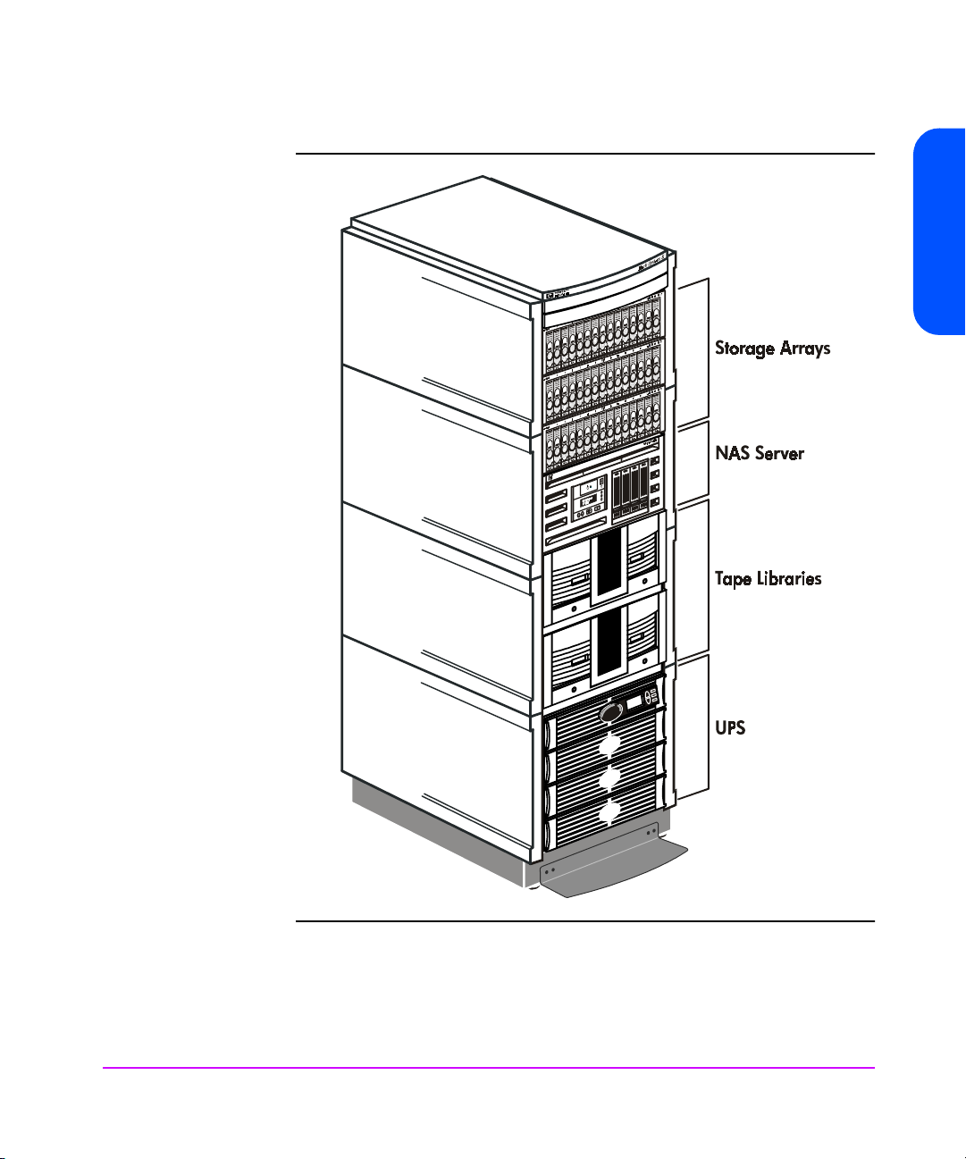
Figure 1 NAS Racked System
HP NAS 8000 Overview
Other accessories sold separately are:
■
Uninterruptible power supply (UPS).
■
HP Surestore tape libraries.
HP NAS 8000 Overview 11
Page 14

Software
The NAS 8000 server comes preloaded with:
■
A custom operating system optimized for file serving. A command line
interface is available for advanced server management.
■
HP Command View NAS management software that runs in a web
browser. This graphical user interface is the primary tool for managing the
NAS 8000. Links to Command View SDM are provided for advanced
array management.
■
HP Virus Guard virus protection software, which is integrated with the
NAS operating system and Command View NAS.
■
A server backup agent for HP OmniBack II 4.1, which is integrated with
the NAS operating system and Command View NAS.
■
File volume snapshot capability for data protection.
If you do not use the NAS 8000 backup agent, you can backup your data
using one of the following network backup software products:
■
HP OmniBack II
■
Computer Associates ARCserve 2000
■
Veritas Backup Exec
■
Veritas NetBackup
■
IBM Tivoli Storage Manager
12 HP NAS 8000 Overview
■
Legato Networker
You can also integrate the NAS 8000 with several network management
software products, including HP OpenView Network Node Manager. For
more information about network management plug-ins, see http://
www.hp.com/support/emsp to learn about the HP Surestore Enterprise
Integrations product.
Additional NAS 8000 integrations with other products, such as Oracle and
SQL server may be possible. See http://www.hp.com/support/nas8000 for
a current description of supported product integrations.
Page 15

Product Configurations
The NAS 8000 is available in four configurations:
■
Direct-attached storage configuration
■
Direct-attached storage configuration with high availability
■
SAN configuration
■
SAN configuration with high availability
Depending on the configuration of your NAS server, different options display
in the Command View NAS web interface.
Direct-Attached Configuration
With direct-attach configurations, one HP VA7100 or VA7400 series disk
array is connected to the NAS server using one Fibre Channel (FC) Host Bus
Adapter (HBA). In addition:
■
The server includes one internal NIC with the option of adding two
additional NICs.
■
The server may include two SCSI or FC HBAs for connecting to an optional
tape library.
■
The server communicates with an optional UPS using a serial connection.
HP NAS 8000 Overview
HP NAS 8000 Overview 13
Page 16
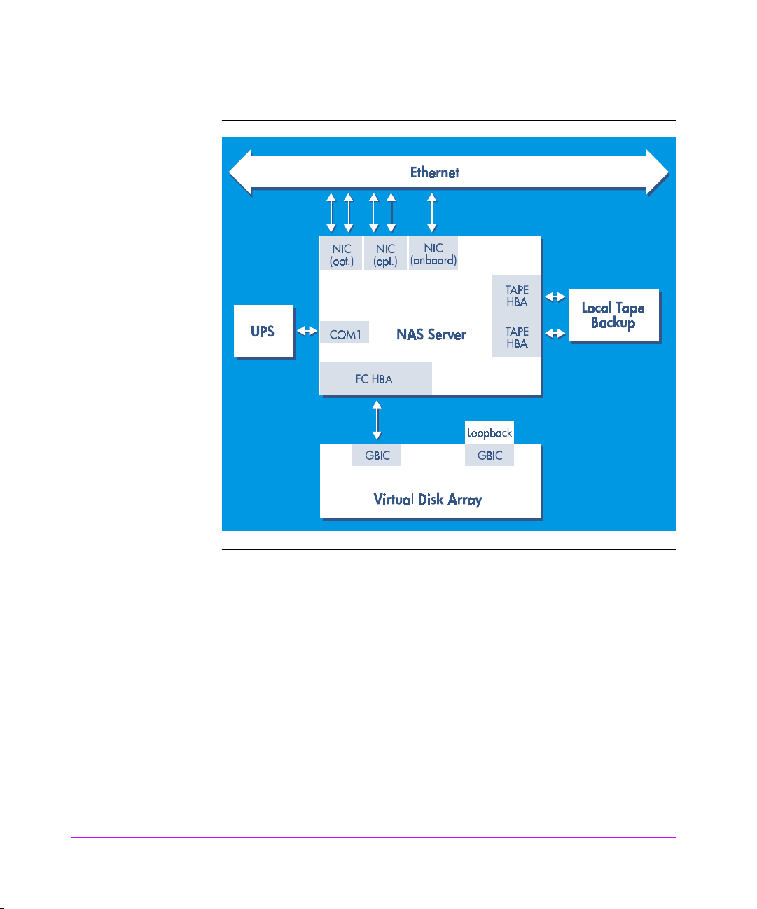
Figure 2 Direct Attached Configuration
Direct-Attached Configuration with High Availability
In direct-attached configurations with high availability, one or two VA7100
or VA7400 series disk arrays are attached to a cluster consisting of two NAS
servers and a Quorum server that manages the high-availability services for
the cluster. In addition:
■
A single HBA is pre-installed in each server.
■
A separate UPS is required for each NAS server.
■
Tape backup can be shared by both NAS servers.
14 HP NAS 8000 Overview
Page 17
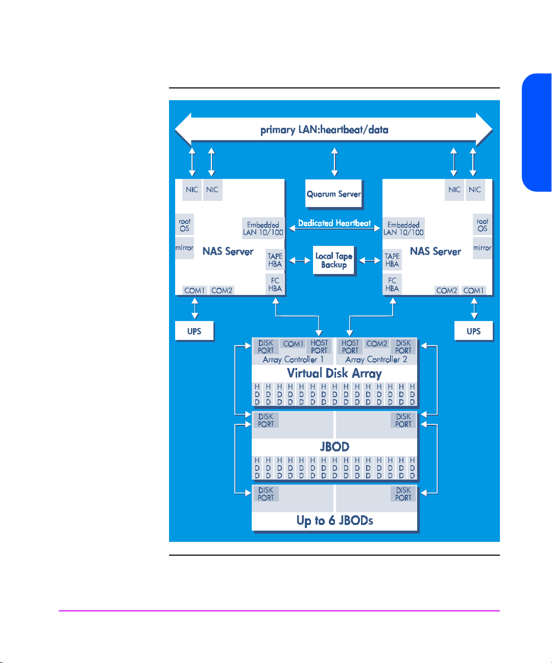
Figure 3 Direct-Attached Configuration with High Availability
HP NAS 8000 Overview
HP NAS 8000 Overview 15
Page 18
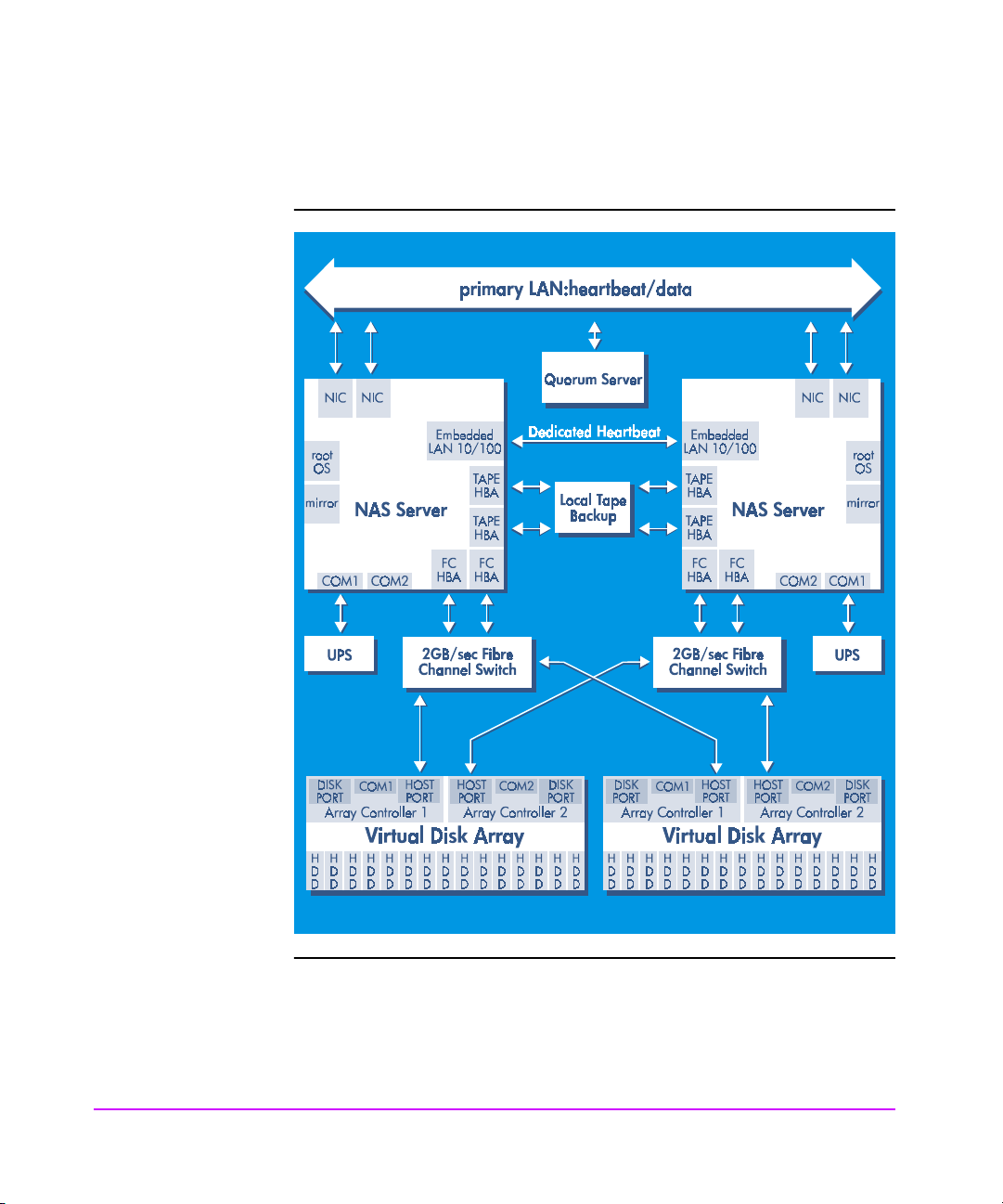
■
Multiple arrays may also be attached using FC switches.
Figure 4 Multiple Arrays with FC Switches
16 HP NAS 8000 Overview
Page 19
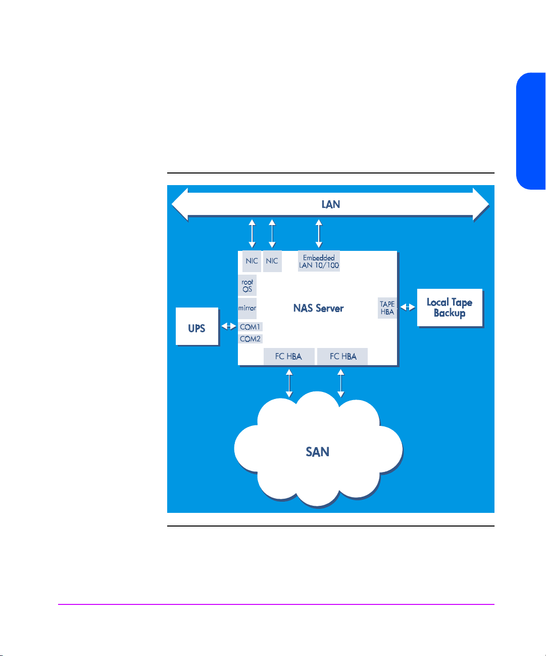
SAN Configuration
HP NAS 8000 Overview
NAS 8000 solutions can also manage storage on HP VA7100, VA7400
series or XP model arrays connected to a SAN. LUNs must be created and
assigned to the NAS 8000 using a product such as HP Surestore Secure
Manager VA or Secure Manager XP.
Figure 5 SAN Configuration
HP NAS 8000 Overview 17
Page 20
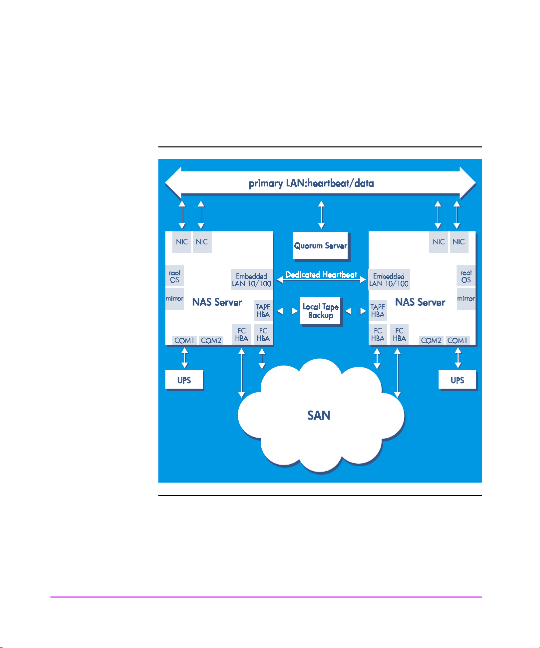
SAN Configuration with High Availability
A high-availability, clustered NAS 8000 system can also be configured to
access VA7100, VA7400 series and XP model arrays attached via SAN.
Figure 6 SAN Configuration with High Availability
18 HP NAS 8000 Overview
Page 21

User’s Guide Overview
This user’s guide is organized into the following chapters:
Chapter Description
HP NAS 8000 Overview
Chapter 1, HP NAS 8000
Overview
Chapter 2, NAS 8000 Concepts Key concepts you need to know about storage and security.
Chapter 3, Getting Started What you need to do to begin using the HP NAS 8000.
Chapter 4, Configuring Your
System and Network
Chapter 5, Managing Your
Storage
Chapter 6, Monitoring the
System
Chapter 7, Enabling Virus and
Backup Software
Chapter 8, Recovering from a
Disaster
Chapter 9, Integrating with
Network Backup Applications
Introduction to the features of the HP NAS 8000.
Set up your system, TCP/IP, networking, and alerts settings. If you
have a high-availability NAS server, enter those settings here. You
can also configure user and group mapping, and monitor UPS
connections.
Set up LUNs, volume groups, failover packages (if you have a highavailability system), file volumes, shares, exports, snapshots, and
quotas.
Monitor the NAS server’s events, environment, components, and
performance. You can also monitor high-availability settings and
any attached arrays.
Use virus-protection software, backup agent, and snapshots to
protect your data.
Restore your storage system to its originally configured state.
Use network backup applications with your NAS server.
Chapter 10, Obtaining Product
Support and Software
Upgrades
Appendices Obtain system and hardware upgrades, trap definitions, legal
Contact support, view Open Source code, run diagnostic tools, and
obtain software upgrades.
information, Command View SDM overview, and the Command
View NAS Command Line Interface.
HP NAS 8000 Overview 19
Page 22

20 HP NAS 8000 Overview
Page 23

NAS 8000 Concepts
Understanding Physical and Logical Storage
The storage space on your HP NAS 8000 is made up of physical storage and
logical storage for a direct-attached and SAN configuration. Before you
begin planning your storage, you need to understand the following concepts.
Physical storage refers to the hardware used for data storage. The physical
storage components of the HP NAS 8000 are the disk drives.
Logical storage is created by software that lets you combine disk space from
multiple physical disks into a logical volume. The logical storage components
of the HP NAS 8000 include:
■
Logical unit numbers (LUNs)
■
Volume groups
■
File volumes
■
Directories
■
Snapshots
2
NAS 8000 Concepts 21
Page 24
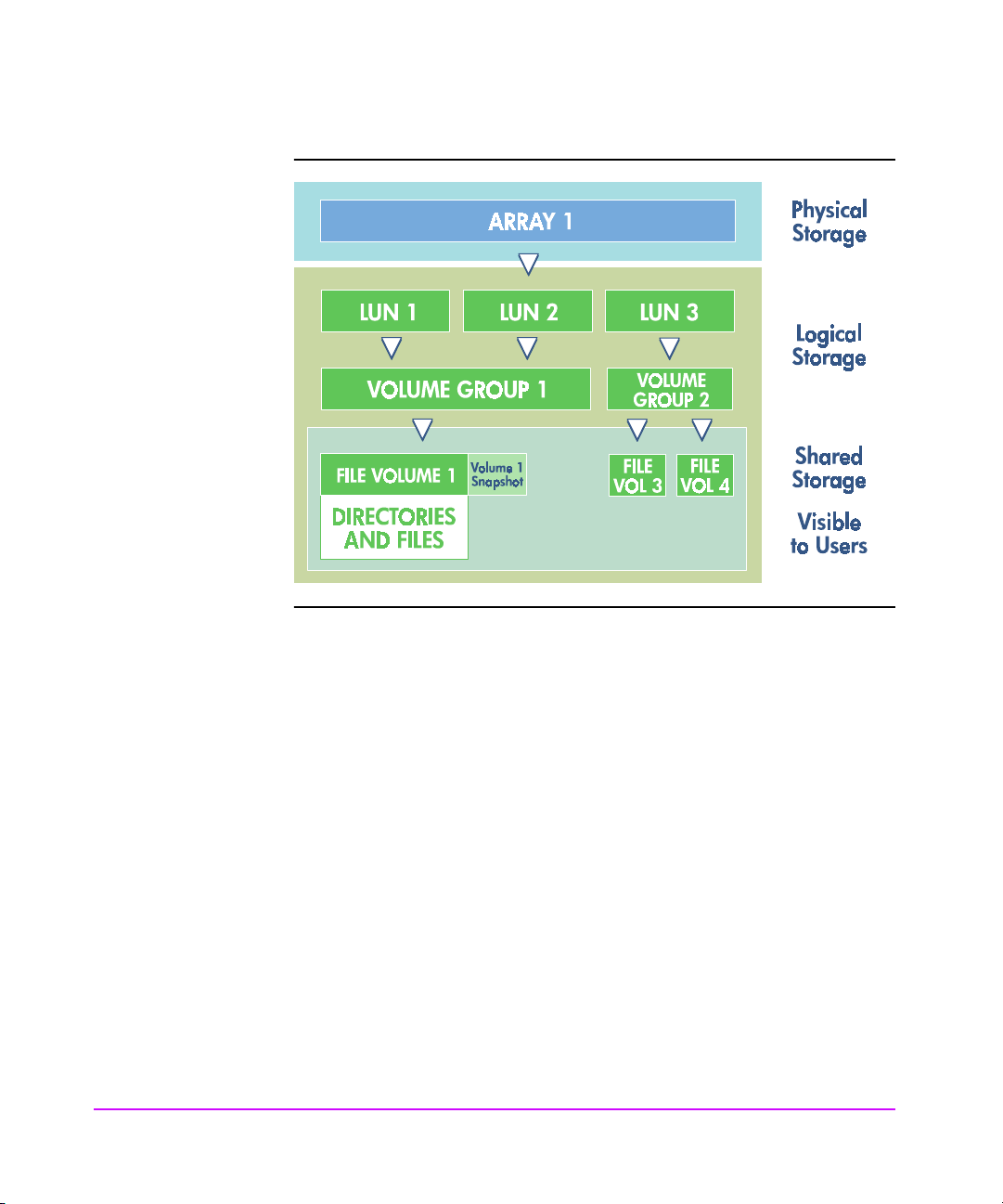
Physical Storage
Figure 1 Physical and Logical Storage
22 NAS 8000 Concepts
Disk Drives
The HP NAS 8000 supports the following storage devices either directly
attached to the NAS 8000 or on a SAN:
■
Virtual Array (VA) 7100 is a disk storage system that holds from 4 to 15
disk drives. The array has scalable capacities from 72 GB to over 1
Terabyte depending upon the size and number of disk drives. The
capacity of the disk drives can be mixed.
■
Virtual Array 7400 series arrays are high-performance, high-availability,
multi-terabyte storage arrays with a 2Gb/s fibre channel host. The
VA7400 series supports up to 105 drives (10 minimum) with additional
DS2400 disk enclosures.
For more information about these drives, see the
VA7100 and VA7400 User And Service Guides
support/va7100 or http://www.hp.com/support/va7400.
HP Surestore Virtual Array
at http://www.hp.com/
Page 25

Logical Storage
The HP NAS 8000 lets you set up your storage into these logical divisions:
Logical Unit Number
A logical unit number (LUN) is a logical aggregation of the space on one or
more physical drives. The HP NAS 8000 supports a maximum of 127 LUNs.
Volume Groups
A volume group is the aggregation of one or more LUNs. Volume groups
combine the space from LUNs and make the space accessible to the file
system for creating file volumes and directories, which can then be made
accessible to users.
File Volumes
A volume group is divided into one or more file volumes. File volumes are the
basic unit of logical storage for a file system on the HP NAS 8000. File
volumes can be further subdivided into individual directories.
Directories
Directories let you organize information. Directories contain files or other
persistent data structures in a file system that contains information about other
files. Directories are usually organized hierarchically and may contain both
files and other directories, and are used to organize collections of files for
applications or convenience.
NAS 8000 Concepts
Snapshots
A snapshot is a read-only picture of a file volume at a specific point in time
that provides almost instantaneous access to the previous snapshot version of
a file.
NAS 8000 Concepts 23
Page 26

Understanding High Availability
Note This section applies only if you have purchased a high-
availability NAS solution.
High availability characterizes a system that is designed to avoid the loss of
service by reducing or managing failures and minimizing downtime. High
availability implies a service level in which both planned and unplanned
downtime is minimized.
Cluster Components
The HP NAS 8000 cluster consists of two NAS servers, a Quorum server and
storage that may come from either a direct-attached configuration or a SAN.
The NAS servers share access to the storage and provide failover capabilities
for each other, but function as independent servers. The main purpose of
high-availability clusters is to provide a higher degree of storage availability
to client systems than is possible with a single server. This is accomplished by
minimizing single points of failure and providing functional redundancy.
Server downtime and interruptions to storage availability are minimized by
failing over file serving capabilities between the NAS servers in the event of a
failure in either server.
24 NAS 8000 Concepts
Page 27
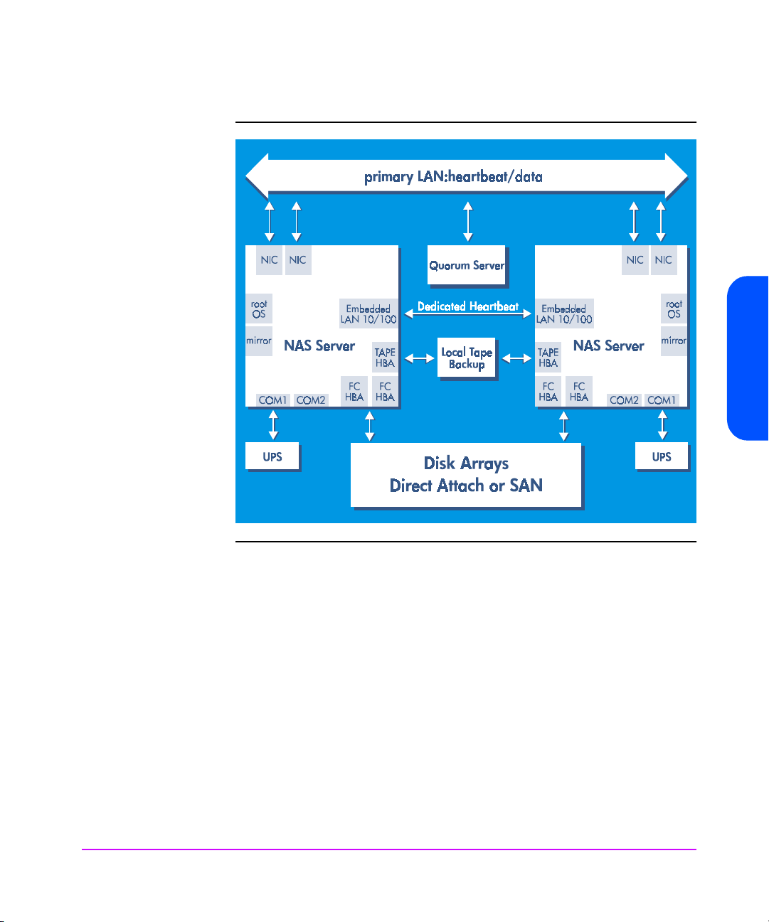
Figure 2 Cluster Components
NAS 8000 Concepts
Failover Models
Failover is a backup operational mode in which the functions of one NAS
server are assumed by the other NAS server when a NAS server becomes
unavailable through failure or scheduled down time.
The following two modes are supported for the NAS servers in the cluster:
■
Active/Active
■
Active/Passive
NAS 8000 Concepts 25
Page 28

Resource Model
Active/Active Failover Model
In the active/active failover model, both NAS servers provide simultaneous
access to storage. Each NAS server maintains separate file systems, CIFS
shares, and NFS exports. The NAS servers do not provide shared access to
the same volumes and file systems simultaneously. Each NAS server functions
as a separate file server. To facilitate file system failover, the NAS servers
have full access to each other's disk resources but do not utilize the shared
access unless a server failure occurs. When the failure criteria have been met
and the failover system directs a NAS server to fail over, the NAS server then
takes over the IP and disk resources of the failed server and begins serving the
file systems and associated shares as if they were its own. Note that both NAS
servers provide CIFS and NFS services.
Active/Passive Failover Model
In the active/passive failover model, only one NAS server is active at a time.
The other NAS server waits in standby mode until a failover occurs. The active
NAS server operates as in the active/active model, providing both CIFS and
NFS services to client systems. Active/passive mode is created by starting
failover packages on only one primary server and configuring the secondary
server to be the failover target in the event of a primary server failure.
26 NAS 8000 Concepts
The cluster has a shared-nothing resource model, which means that each
server has exclusive access to the storage (volume groups, volumes, and
shares) and network resources (hostname, package names, IP addresses) that
it's serving. The cluster nodes can see each others’ storage and are aware of
each others' packages and IP addresses, but by agreement and design, they
activate only the storage and network addresses to which they are currently
assigned. The clustering system strictly enforces this agreement to prevent
concurrent or shared access to the same storage resources. The file system
that is used for each file volume is not distributed and does not support
simultaneous shared access. The cluster Quorum server’s primary job is to
enforce the shared-nothing cluster policy.
Page 29

Failover Packages
Failover packages are the smallest unit of failover within the cluster. A
package contains necessary definitions and configuration information
relating to resources and their processes that must be failed over to the
secondary server in the event the primary server fails. Each cluster can have a
maximum of 30 packages running concurrently. For NAS, the package
defines the volumes (file systems) and their associated CIFS shares and NFS
exports that should be failed over. A given volume group can be defined in
only one package at a time, but a package can contain multiple volume
group definitions. The packages can fail over automatically when a server
fails, or they can be manually failed over one at a time. A given package can
be running on only one cluster node at a time.
Think of a package as a group of one or more volume groups (with their file
systems and shares/exports) that will fail over as a single unit. To fail over a
package manually, you need to:
■
Stop the existing package (in the case of a service, network, or resource
failure).
■
Start the new instance of the package on a different node.
You can manage failover packages on the Storage tab of the Command View
NAS web interface.
Eliminating Single Points of Failure
NAS 8000 Concepts
Most problems that result in service outages are single-level failures. Highavailability lets you quickly detect and handle these failures and minimize
downtime. Examples of single-level failures include:
■
NIC failures
■
NFS failure
■
SMB failure
■
Operating system failure
■
Power failur e
NAS 8000 Concepts 27
Page 30

High-Availability Options in the Command View NAS Web Interface
You can manage high-availability options on the following tabs of the
Command View NAS web interface:
■
Configuration tab: Start or stop clustering services; manage node settings
for your cluster; name your cluster; enter a name for the Quorum server;
and set up timeouts and intervals for the cluster.
■
Storage tab: Add, edit, delete, start, and stop failover packages. You can
also manually fail over or fail back a package.
■
Status tab: Monitor nodes and failover packages.
28 NAS 8000 Concepts
Page 31

About HP NAS Server Security
Two basic ways to ensure the security of the NAS server are:
■
Control access to the device
■
Set an administrative password to ensure that only authorized users gain
access to key administrative functions
Access and rights to the data that clients store on the NAS server can involve
security in the Windows® and UNIX® environments. This section discusses
key security elements that you might consider when administering your NAS
server.
HP NAS Server Security in a UNIX-only Environment
UNIX uses a reasonably simple approach to data access security. Each
workstation performs user authentication locally. Each user is associated with
a 16-bit integer (user ID or UID). Additionally, each user can be a part of a
group that is denoted by another 16-bit integer (group ID or GID). A user can
be a member of several groups, each with its own unique GID. All objects
contain associated meta-data that includes the UID and GID as well as read/
write/execute permissions for the object. A typical UNIX file permission might
look like:
-rwxr-xr-x 1 201 5 611 Nov 11 11:09 testfile
-rwxr-xr-x 1 Wilson Engineering 611 Nov 11 11:09
testfile
NAS 8000 Concepts
In the first line, numbers represent the UID and GID; in the second line, the
names associated with the UID and GID are displayed. In either case, Wilson
(UID 201), who is a member of the Engineering group (GID 5), created a file
that has permissions for three different groups. The permissions are
represented by a string of nine characters: three characters for the
permissions of each of the three groups of users. The three groups are the
owner (Wilson), the group (Engineering), and other. In the example above,
the owner has specified rwx (read/write/execute) privileges for himself, r-x
(read/execute) privileges for the group, and r-x (read/execute) privileges
for other.
In your network, you might use a Network Information Service (NIS) server to
help you maintain common configuration files such as the password, group,
and host files. If your environment uses a NIS server, you can enable NIS. The
NAS 8000 Concepts 29
Page 32

NAS server then maintains the same UID and GID numbers that your UNIX
users are currently assigned in a heterogeneous environment.
Note Whether you disable or enable the use of a NIS server, you are
in no way affecting the security of a homogenous UNIX
environment.
An additional form of security called host access is available in the UNIX
environment and controls which client machines are allowed access to the
NAS server, regardless of the user. The allowed clients are specified by a list
of IP addresses or hostnames representing those machines. Host access
controls access by machine, not user.
HP NAS Server Security in an NT-only Environment
The security schema for NT systems is different from that of UNIX, but there
are two similarities:
■
You can set up the security model to allow user authentication at the share
level; alternatively, you use a security domain, in which authentication is
handled by a Primary Domain Controller (PDC) or Backup Domain
Controller (BDC).
■
Processes are run with an identity of a user and any groups to which that
user belongs for either that workstation or the domain. Each data object is
associated with meta-data, sometimes called a security descriptor (SD).
The security descriptor contains a list of permissions or denials in the
Access Control List (ACL), which contains an almost limitless number of
permutations that can be associated with a data object.
30 NAS 8000 Concepts
The NAS server lets you choose between two security models:
■
Share-level security
■
User-level (Domain) security
Additionally, host access is available in the NT environment to control which
client machines are allowed access to the NAS server, regardless of the user.
The allowed clients are specified by a list of IP addresses or hostnames
representing those machines. Host access controls access by machine, not
user.
Page 33

Share-Level Security
With share-level security, the server explicitly asks for permission (password)
every time a user connects to a share on the NAS server. Thus, any user on
the network who knows the name of the NAS server, the name of the resource
(or file), and the password has access to the resource. When you are using
share-level security, you can assign shares a read-only password and/or a
read-write password.
User Level (Domain) Security
With user-level security, the client accessing the NAS server passes the
credentials of the logged-on user to the NAS server system transparently. The
NAS server in turn queries the Primary Domain Controller (PDC) or Backup
Domain Controller (BDC) to authenticate the user. Once the user is
authenticated, the PDC or BDC returns a Security ID (SID) that the NAS server
uses to check the client's access rights. This token is then used with all
subsequent requests from that client.
The NAS server supports the NT Master Domain model. This allows the NAS
server to participate in a resource domain that is separate from the domain in
which users are authenticated.
Figure 3 NT Master Domain Model
NAS 8000 Concepts
At boot-up time, the NAS server locates the PDC in the specified account
domain, as well as the domain controller in the specified resource domain,
then logs on to that domain.
NAS 8000 Concepts 31
Page 34

Permissions
You can assign the following permissions to an NT resource:
■
Read
■
Delete
■
Write
■
Execute
■
Change Permissions
■
Take Ownership
Additionally, you can group these permissions into standard permissions that
consist of one or more previous permissions. These standard permissions
include:
■
No Access
■
Read
■
Change
■
Full Control
■
Special Access (where individual permissions can be selected, such as
Read + Change Permissions)
Sharing Files Across Multiple Platforms
Sharing Files Across Multiple Platforms
Sharing Files Across Multiple PlatformsSharing Files Across Multiple Platforms
32 NAS 8000 Concepts
The NAS server was designed to work well in a heterogeneous environment
and support remote file access protocols for UNIX and NT clients. A major
difficulty in sharing data across these environments is that the file system
security models are very different. For example, NT systems that use user-level
security use ACLs to identify both themselves and the permissions for each
data object, whereas UNIX systems use traditional UNIX permissions that
define explicit permissions for the user, group, and other. However, given
some care in setting up the security environment, a reasonable level of access
can be provided for cross-environment requests (i.e., a UNIX client requesting
a file created by an NT client) without overly compromising the security set by
the creator of the object.
Page 35

Accessing Files Created by UNIX Clients
When an NT user accesses a UNIX file, the UNIX file permissions are
translated into an ACL that then determines the permissions to grant. Recall
from HP NAS Server Security in a UNIX-only Environment that permissions
are granted to three distinct groups:
■
user
■
group
■
other
If the owner of the UNIX file does not map to a user in the NT domain, then
an NT user ID will be generated in the local UNIX domain. If the owner of the
UNIX file is recognized (or mapped) as a known NT user, then the
appropriate information will be exchanged so that the owner has the same
security privileges in NT that he or she had in UNIX. A similar process occurs
for the group identification and permissions. The Other field is mapped to the
NT Everyone account.
This table shows the mapping that takes place between the permissions.
UNIX NT Equivalent
r-- Read
-w- Write, Delete
NAS 8000 Concepts
--x Execute
-wx Write, Delete, Execute
r-x Read, Execute
rw- Read, Write, Delete
rwx Full Access
--- No Access
Note If share-level security is being used in the Windows
environment, then only the share passwords affect access. The
UNIX permissions have no effect.
NAS 8000 Concepts 33
Page 36

Accessing Files Created by NT Clients
Directly mapping NT permissions to UNIX permissions causes some difficulty
because NT permissions have a greater level of complexity. UNIX users are
unable to use either the chmod or chown commands to modify the
permissions or owners of NT files. The table below shows which UNIX-to-NT
file permissions are mapped.
NT UNIX
R r
W w
X x
D Ignored
P Denied
O Denied
In addition to the permission mappings covered in the previous sections, the
following also applies:
■
If no ACLs are specified, then the UNIX permission will be rwxrwxrwx.
34 NAS 8000 Concepts
■
If the ACL is empty, then the UNIX permissions will be ---------.
■
If the only access allowed by the ACL grants full control to everyone, then
the UNIX permissions will be rwxrwxrwx.
■
In the absence of a group ACL, the owning group will be the user's
primary group and the group permissions are set to the same value as the
other permissions.
Additionally, if an NT file grants permission to the everyone group (and does
not specifically deny access to the owner or the group), then the same access
is given to the owner and the primary group. However, UNIX permissions
look for explicit permissions for the owner, group, and other. To allow the
same level of access in UNIX as NT, these files will have a permission of
r--r--r--.
Page 37

Getting Started
3
Using the Command View NAS Web Interface
The NAS server and storage array are managed via a web browser. You will
perform most administrative tasks with this interface. The Command View
NAS requires the Sun Microsystems Java™ Plug-in 1.3.1_01, Standard
Edition. Supported browsers include Internet Explorer 5.5 and Netscape 4.77.
For more information on supported browser versions for Windows, Solaris,
and Linux platforms, see http://java.sun.com/products/plugin/. For
information on supported browsers for any other platforms, contact your
operating system vendor.
Depending on your product configuration, different options display in the
Command View NAS web interface.
To access the Command View NAS web interface:
1 Start a web browser on a computer on the network.
2 Enter the IP address of the HP NAS 8000 in the address or location field.
The first time you access the Command View NAS, the Configuration
Wizard guides you through configuration. After the initial configuration,
an Identity page appears (see Figure 1).
Getting Started 35
Page 38

Figure 1 Identity Page
36 Getting Started
Note If you have trouble connecting, try enabling the browser's
option to bypass the proxy server for local addresses.
You can click the tabs at the top of the web interface to access the following
sections:
■
Identity:::: To view general system information
■
Status: To view overall health of hardware and environmental components
on the NAS head and the overall health of any attached storage array;
monitor high-availability settings if you have a high-availability NAS
server
■
Storage: To view and manage arrays, LUNS, volume groups, failover
packages (if you have a high-availability NAS server), file volumes,
directories, data access, snapshots, and quotas
Page 39

■
Configuration: To initialize, view, and modify system, network, and alert
settings; shutdown/restart the system; set up user and group mapping;
configure high-availability settings if you have a high-availability NAS
server
■
Applications:::: To enable/disable and manage installed software
■
Support: To contact service and support for the HP NAS 8000; obtain
open source code; run diagnostic tools; upgrade the NAS server software;
upgrade storage array firmware
When you select any tab other than Identity, a navigation tree appears in the
left pane (see Figure 2). A plus sign next to a selection indicates that it
contains subentries. To access the subentries, click on the plus sign to expand
the tree, or double click on the entry.
Figure 2 Command View NAS
Getting Started
The Command View NAS web interface also lets you perform complex
storage array management tasks by launching the Command View SDM.
Getting Started 37
Page 40

Make sure you review Command View SDM Limitations before using the
software.
Downloading the Sun Microsystems Java™ Plug-In
To launch the Command View NAS, you must have installed the Sun
Microsystems Java™ Plug-in 1.3.1_01, Standard Edition. You can download
this plug-in if needed as follows:
For Sun Solaris/Windows/Linux
1 Go to the Sun Microsystems web site at http://java.sun.com/products.
2 Select the Java™ 2 Platform, Standard Edition hyperlink.
3 Select the appropriate download product and follow the instructions for
installation on your system.
The Sun Microsystems web site also has installation instructions for
configuring your browser so that it can access the plug-in software.
For HP-UX
For an HP-UX system, go to http://www.hp.com/products1/unix/java/ and
follow the download instructions for the latest version of the Java™ Platform
Plug-in.
38 Getting Started
Page 41

Using Online Help
You can access the NAS server’s online help from the Command View NAS
web interface. Click or the Help button in the dialog box windows to
access online help. The Command View NAS web interface then opens a toplevel help menu. This context-sensitive online help is preloaded on your NAS
server.
Help is organized into main-level and sub-level topics. The icon tabs in this
help system are:
■
Contents: Displays folders and pages that represent the categories of
information in the online user’s guide. When you click a closed folder, it
opens to display its content (subfolders and pages). When you click an
open folder, it closes. When you click pages, you select topics to view in
the right-hand pane.
■
Index: Displays a list of keywords and keyword phrases. These terms
are associated with topics in the help system. To open a topic in the righthand pane associated with a keyword, double-click the keyword.
Printing Help Information
While using the online help, you can print topics and information directly
from the viewer. The available print options are determined by the version of
your browser.
Click the print icon ( ) and select your print options.
A printable version (PDF format) of all online help, called the
NAS 8000 User’s Guide
and on the HP support web site at http://www.hp.com/support/nas8000.
, is available on your production documentation CD
HP Surestore
Getting Started 39
Getting Started
Page 42

Task Overview
Prerequisites
During setup, your NAS 8000 was installed and configured by an HP storage
specialist who performed these tasks:
1 Planned your network and storage settings.... You should have done this
with your HP installation specialist prior to receiving the product. See your
HP Surestore NAS 8000 Solution Integration Manual (SIM) Binder for
your
Network and Storage Planning Guide
and Logical Storage” on page 21 in this user's guide for more
information.
and “Understanding Physical
2 Installed the NAS 8000 hardware.... For information, see the
3 Configured your system and network.... For information, see the
4 Set up storage.... For information, see the
Management Tasks
After the prerequisite tasks are done, you are ready to perform other storage
management tasks such as:
■
■
HP Surestore
NAS 8000 Installation Guide
in your SIM Binder.
HP
Surestore NAS 8000 Installation Guide
Configuring Your System and Network on page 43.
in your SIM Binder and
HP Surestore NAS 8000
Installation Guide
page 77.
Configure additional system and network settings (see Chapter 4,
Configuring Your System and Network). You can change these when
something about your system changes (location, system administrator,
new user or group mappings). See .
Manage your storage (see Chapter 5, Managing Your Storage). Most
storage settings were properly set during setup. You will need to change
them if you change your storage configuration or if you choose options
such as renaming/adding arrays or working with snapshots. Make sure
you understand storage concepts before proceeding. See “Understanding
Physical and Logical Storage” on page 21 for more information.
in your SIM Binder and Managing Your Storage on
40 Getting Started
Page 43

■
Monitor your system by viewing settings on the Status tab (see Chapter 6,
Monitoring the System). You'll need to check the status of your system if
there is a problem (your system may be set up to automatically notify you
of problems).
■
Determine a virus and backup strategy (see Chapter 7, Enabling Virus
and Backup Software). The HP NAS 8000 provides a backup agent,
disaster recovery, virus protection, and snapshots functionality to protect
your data.
■
Prepare for a disaster (see Chapter 8, Recovering from a Disaster).
■
Integrate with network backup applications (see Chapter 9, Integrating
with Network Backup Applications).
■
Contact HP support (see Chapter 10, Obtaining Product Support and
Software Upgrades).
■
Upgrade the server software (see Chapter 10, Obtaining Product
Support and Software Upgrades).
Getting Started
Getting Started 41
Page 44

42 Getting Started
Page 45

Configuring Your System and Network
During installation, an HP storage specialist configured your system as part of
setup using the web-based Configuration Wizard in the NAS 8000 web
interface. (See the
Binder for information.)
Now you may want to make changes to your settings. You can do so through
the Configuration tab, which contains the following configurable parameters:.
■
System Properties. These are informational settings. You can specify the
system name, date and time as well as password-protect the
administration of your NAS 8000 web interface.
■
TCP/IP Settings. These settings allow you to set up your device on several
network protocols. You enter your IP address and Domain Name Service
information here.
■
High Availability.* You can enter your node settings, name your cluster
and Quorum server, set timeouts and intervals, and start and stop
clustering services.
■
Networking Settings. The HP NAS 8000 supports Windows and UNIX
networking protocols.
HP Surestore NAS 8000 Installation Guide
4
in your SIM
■
Alerts/Logging. You can enter these optional settings if you want to
receive email or server (SNMP) notification in case of a hardware failure
or system alert. You can specify a remote server to which you can redirect
a copy of the system log.
■
Mapping. You can map Windows users to UNIX users or Windows
groups to UNIX groups.
*This option only appears if you have a high-availability NAS server.
You also can select the UPS connection, manage quotas, modify the storage
subsystem, and shut down or restart the device from the Configuration tab.
After you have configured your system to meet your requirements, go to the
Storage Tab to arrange the storage space to fit your needs and configure
quotas.
Configuring Your System and Network 43
Page 46

Using the Configuration Wizard
The Configuration Wizard automatically appears the first time you connect to
the NAS server using a web browser. After that, you can access the wizard to
perform guided configuration tasks as follows:
■
Open the Command View NAS web interface by typing the IP address in
the address or location field of a web browser (you configured this
address during installation). The Wizard (shown below) guides you
through configuration.
or
■
Access the Wizard through the Configuration tab of the Command View
NAS web interface by clicking Configuration Wizard > Actions > Launch
Wizard.
Note Do not use your browser's Forward, Back, or Refresh buttons
while the Configuration Wizard is running. Instead use the
Back and Next buttons in the Wizard.
Figure 1 Configuration Wizard
44 Configuring Your System and Network
Page 47

The Wizard lets you:
■
Define your system name
■
Set the date and time
■
Enter your contact information
■
Set UPS monitoring
■
Specify a password
■
View the Command View NAS access list
■
Define your TCP/IP addresses
■
Enter DNS settings
■
Enter your node settings, cluster name, Quorum server name, and
timeouts and intervals if you have a high-availability NAS solution
■
Set up your Windows (WINS properties and security settings) and UNIX
(NIS and NFS settings) environments
■
Set SNMP and email (SMTP) alerts
■
Enter an address for remote system log data
The Command View NAS web interface also lets you manually configure
these settings within the Configuration tab. If your network configuration
changes, you need to update these settings.
For specific help on a particular section in the Wizard, click the Help button.
Configuring Your System and Network 45
Configuring Your System and
Network
Page 48

Identifying your NAS Server
The first time you access Command View NAS, the Configuration Wizard
appears to guide you through configuration. Subsequent times when you
access Command View NAS, an Identity page appears and displays the
following general system information:
■
*Name — The system or hostname for your HP NAS 8000
■
*Cluster Name (high-availability configurations only) — Name of your
cluster on your network
■
*Sibling Node (high-availability configurations only) — The secondary
node (server) in your cluster if you have a high-availability NAS server
■
Description — HP NAS 8000
■
Manufacturer — Hewlett-Packard Company
■
Product Number — The product number corresponding to the original
configuration of the HP NAS 8000
■
*Location — The physical location of the HP NAS 8000
■
*Contact Name — The person to be notified in case of trouble or
questions about the HP NAS 8000 (usually the system administrator)
■
*Contact Phone Number — Usually the phone number of the contact
name
■
*Asset Number — A number that your company might use to identify and
track the HP NAS 8000
■
System s/n — The factory-set serial number of the unit
■
*IP Address — The IP network address of the Network Interface Card
(NIC) in port 1 (although the HP NAS 8000 supports multiple ports, only
the first one is displayed)
■
MAC Address — The unique Machine Address Code for the NIC in port 1
■
OS Version — The current version of the operating system running on the
HP NAS 8000
■
+Array Alias/ID — The name you gave the array and the array serial
number (if you have a SAN configuration, this does not display)
■
Worldwide ID (SAN only) — Associated ID with the host bus adapter
■
Up Time — The cumulative up-time of the HP NAS 8000 since the last
reboot
*You can change these items from the Configuration tab.
+You can change this from the Storage tab.
46 Configuring Your System and Network
Page 49

Shutting Down and Restarting
Direct-Attached and SAN Configuration
The Shutdown/Restart option applies only to the NAS server. If you need to
shut down a direct-attached storage array, shut down the NAS server first.
Shut down the NAS server if you:
■
Move the device to a new location
■
Anticipate a power outage in your building and you do not have an
uninterruptible power supply for the device
Restart the NAS server if you install a new version of the Command View
NAS web interface.
Note When restarting the NAS server in a direct-attached
configuration, it is not necessary to shut down or restart the
storage array.
When shutting down or restarting the server, keep in mind that:
■
You and any other connected users will lose the connection to the device.
■
The Command View NAS web interface in the current browser cache
becomes invalid. The browser closes and you must re-connect to the
system after it reboots.
To shut down or restart the device:
1 In the Command View NAS web interface, click the Configuration tab,
then navigate down the tree and select Shutdown/Restart.
2 Click Actions > Shutdown/Restart.
3 Select:
— Shutdown if you want to shut down the NAS server completely.
— Shutdown/Restart if you want to shut down and restart the NAS
server. If you have installed new firmware, the system will use it on
reboot. Wait approximately five minutes for the system to be restored.
4 Click OK.
Configuring Your System and Network 47
Configuring Your System and
Network
Page 50

High-Availability Configuration
If you have a high-availability NAS server, you have several shutdown
options:
■
Stop the server and do not fail over packages. You can manually stop
each package, then stop the server, or you can stop the server and cause
the packages to stop automatically. Once the server is stopped, it is no
longer active in the cluster and is not serving any file systems, so you can
safely stop it by following steps 1-4 in “Direct-Attached and SAN
Configuration” on page 47.
■
Fail all packages over to the other server. To do so, simply stop each
package and restart it on the other server. Once the packages are all
failed over, you can stop the server (take it out of the cluster), then follow
steps 1-4 in “Direct-Attached and SAN Configuration” on page 47.
■
Fail selected packages over to the other server. This option is similar to the
previous option, except that you fail over only selected packages.
■
Stop the entire cluster by taking both servers down. You can either
manually stop all packages on both servers, then stop the cluster, or
simply stop the clustering services to automatically stop all packages.
Once the clustering service is stopped, follow steps 1-4 in “DirectAttached and SAN Configuration” on page 47 on each server.
48 Configuring Your System and Network
Page 51

Configuring System Security
Editing the Command View NAS Access List
The Command View NAS access list allows you to define the machines that
may access the Command View NAS web interface. If a specific machine's
hostname or IP address is not listed, that machine cannot access the
Command View NAS.
To set up the Command View NAS access list:
1 In the Command View NAS web interface, click the Configuration tab.
2 Navigate down the tree to System Security.
3 Select Actions > Edit GUI Access List.
4 Enter the IP address or hostname, then click the add-item icon or press
Enter.
Setting an Administrative Password
You can set a password for the NAS server. This prevents unauthorized
access to the Command View NAS web interface. The NAS server ships
without password protection, and the fields are initially blank.
Note If you set a password for the NAS server, protect it as you
would any other password. If you forget or lose this password,
you will not be able to access your device. Call HP Support for
assistance.
If you specify a password, you must know the password to view or modify the
information in the other tabs. You can not access the Command View NAS
web interface without the password.
To assign, change, or remove an administrative password:
1 In the Command View NAS web interface, click the Configuration tab.
2 Navigate down the tree to System Security.
3 Select Actions > Edit Admin Password.
Configuring Your System and Network 49
Configuring Your System and
Network
Page 52

4 In the Current Password field:
— If you are assigning a password for the first time or if you removed
your password, leave this field blank.
— If you are changing or removing the administrative password, enter
the current password in this field.
5 In the New Password field:
— If you are assigning a password for the first time or changing your
password, enter a password in this field. Use any combination of
printable characters (ASCII codes 32 through 126) with the exception
of \,/, |, !, %, ` (back quote), ' (single quote), and ".
— If you are removing the administrative password, leave this field blank.
6 In the Password Confirmation field:
— If you are assigning a password for the first time or changing your
password, confirm the new password by typing it in this field.
— If you are removing the administrative password, leave this field blank.
7 Click OK.
8 The next time you access Command View NAS, enter the name “admin”
and use the password you created.
Caution If you remove or neglect to assign an administrative password,
the Command View NAS web interface will be accessible to
anyone who knows its IP address.
50 Configuring Your System and Network
Page 53

Configuring System Settings
Defining the System Name
Note If you have a high-availability NAS server, you must stop
clustering services to edit the information.
The system name uniquely identifies your NAS server on your network. It is a
text string that contains as many as 15 characters drawn from the alphabet
(A-Z), digits (0-9), and minus sign (-). No distinction is made between upper
and lower case. However, the name must begin with a letter and the last
character must not be a minus sign. The name you use appears on the Identity
screen of the web interface and in Network Neighborhood in a Windows
networking environment.
To define the system name:
1 In the Command View NAS web interface, click the Configuration tab.
2 Navigate down the tree to System Properties.
3 Click Actions > Edit System Name. Enter your system name (not the
domain) in the System Name field. You can use any combination of
numbers, letters, or dashes to name your device. However, the name must
begin with a letter.
4 Click OK.
Configuring Your System and Network 51
Configuring Your System and
Network
Page 54

Setting the Date and Time
The NAS server uses the information on this screen to keep track of the date
and time for operations such as time stamps for file generation and
modification. Failure to set the proper date and time may lead to confusing
behavior or misleading time stamping of files and log messages.
To set the system date and time:
1 In the Command View NAS web interface, click the Configuration tab.
2 Navigate down the tree to System Properties.
3 Click Actions > Edit System Time.
4 Select either:
— System time and choose the date and time information.
— Network Time Protocol (NTP) and choose a server with which the NAS
8000 can synchronize system time.
5 Click OK.
Assigning Contact Information
Some of the Contact Information that you enter appears on the Identity screen
of the Command View NAS web interface. These items are denoted with an
asterisk (*). Network management tools may also function according to the
contents of these fields.
To assign contact information:
1 In the Command View NAS web interface, click the Configuration tab.
2 Navigate down the tree to System Properties.
3 Click Actions > Edit Contact Information.
4 Enter the:
— Name of the person primarily responsible for the NAS server in the
*Contact Name field
— Phone number of the person primarily responsible for the NAS server
in the *Contact Phone Number field
— Pager number of the person primarily responsible for the NAS server
in the Contact Pager Number field
— Email address of the person primarily responsible for the NAS server
in the Contact Email Address field
52 Configuring Your System and Network
Page 55

— Description of the NAS server's physical location in the *Location field.
— Description of the NAS server's specific position on your hardware
rack in the Rack ID field
— Device's specific location of the rack at your location in the Rack
Position field
— Number that your company might use to identify and track the NAS
server in the *Asset Number field
5 Click OK.
*Information appears on the Identity screen.
Note Blank fields do not affect the functionality of the device.
However, entering your system location (including rack ID and
rack position) lets you easily determine which device has issued
an alert when you receive notification of an error. (The email
message contains the system name.) If you provide your system
location information, you can easily troubleshoot or repair the
problem.
Configuring Your System and Network 53
Configuring Your System and
Network
Page 56

Configuring TCP/IP Settings
Defining IP Addresses
Note If you have a high-availability NAS server, you must stop the
clustering services to edit the information.
The NAS server has one Network Interface Card (NIC) port on the
motherboard and supports two additional slots for NICs. These cards can be
either dual-port 10/100 cards or single-port gigabit cards. This support gives
the system up to five NIC ports (one on the motherboard and the capacity for
a maximum of two dual-port 10/100 NICs).
When you initially set up your NAS server, you need to configure the primary
NIC. Connect a laptop to the server management port using a null-modem
serial cable, and use terminal emulation software to log in. Access the text
interface to manually configure the primary NIC (unless you have Dynamic
Host Configuration Protocol [DHCP]). You can use the Command View NAS
web interface to configure additional NICs. However, you must first configure
the network settings through the serial port or you will not be able to access
the HP NAS 8000 through the web-based user interface. See the
Surestore NAS 8000 Installation Guide
Note DHCP is not supported in high-availability configurations.
HP
for more information.
The following list shows what BOOTP/DHCP vendor options are supported:
■
BOOTP_OPTION_NETMASK
■
BOOTP_OPTION_GATEWAY
■
BOOTP_OPTION_DNS
■
BOOTP_OPTION_DOMAIN
■
BOOTP_OPTION_BROADCAST
■
BOOTP_OPTION_HOSTNAME
■
DHCP_OPTION_WINS
■
DHCP_OPTION_LOGSRVS
■
DHCP_OPTION_LPRSRVS
■
DHCP_OPTION_NTPSRVS
■
DHCP_OPTION_XFNTSRVS
■
DHCP_OPTION_XDMSRVS
54 Configuring Your System and Network
Page 57

If you have DHCP enabled, NIC configuration occurs automatically.
Depending on your configuration, the DHCP server provides any or all of the
following parameters: IP Address, Subnet Mask, Gateway Address,
Broadcast Address, and DNS Domain Name.
To edit the IP configuration for a NIC port:
1 In the Command View NAS web interface, click the Configuration tab.
2 Navigate down the tree to TCP/IP > IP Addresses. A table lists:
— NIC Ports and Bond Channels
— Address configuration (whether it is manual, DHCP or bonded to a
bond channel)
— IP Address
— Gateway Address
— Subnet Mask
— Broadcast Address
— Management Port
— MAC Address
— Card speed
3 Select the Port you want to edit then select Actions > Edit Selected IP
Configuration.
4 Select an address configuration (manual or DHCP) from the drop-down
list. For a manual configuration, enter the IP Address, Gateway Address,
Subnet Mask, and Broadcast Address.
5 Click OK.
Configuring Your System and Network 55
Configuring Your System and
Network
Page 58

Defining the Command View Management Port
The Command View Management Port lets you define a secure port through
which the NAS server and the Command View NAS web interface can
communicate. The port is defined by port designation such as eth0 and eth1;
it is not defined by IP address. eth0 is
default management port.
To define the management port you must use the command line interface
rather than Command View NAS (see Appendix E, Command View NAS
Command Line Interface for directions on accessing the command line
interface).
To set the management port:
setSystemManagementNetworkCard ethX
To verify that the management port has been set up correctly:
getSystemManagementNetworkCard
This command will return the name of your management port.
always
the on-board port and is the
Enabling Bonding
Note
When you configure NIC ports, you may enable bonding through the
command line interface rather than Command View NAS (see Appendix E for
directions on accessing the command line interface). The bonding mechanism
allows for failover of NIC ports when one of the NIC ports fails or abnormally
terminates.
To bond the ports take the following steps:
■
Configure the first port manually (this can be done through the Command
View NAS or using the command line interface)
— setNetworkCardIpAddress ethX X.X.X.X (first parameter is the port
— setNetworkCardBroadcastAddress ethX X.X.X.X (first parameter is
■
You will be able to communicate with the Command View
NAS only through the designated management port with the IP
configuration that you have designated for that port.
■
If you change the port to a non-configured port, you will not
be able to communicate with the server.
designation and second parameter is the IP address).
the port designation and second parameter is the broadcast address).
56 Configuring Your System and Network
Page 59

— setNetworkCardSubnetMask ethX X.X.X.X (first parameter is the port
designation and second parameter is the subnet mask).
— setNetworkCardGatewayAddress ethX X.X.X.X (first parameter is
the port designation and second parameter is the gateway address).
■
Enslave the first port to the bond. The bond will then assume the IP
configuration of the first port enslaved.
— bondEnslaveNetworkCard ethX bondY (first parameter is the port
being enslaved into the bond that is designated by the second
parameter).
■
Enslave the second port to the bond.
— bondEnslaveNetworkCard ethY bondY (first parameter is the port
being enslaved into the bond that is designated by the second
parameter).
To un-bond the ports take the following steps:
■
bondReleaseNetworkCard ethY bondY (first parameter is the port being
un-bonded from the bond that is designated by the second parameter).
Note The ports are being un-bonded in the reverse order that they
were enslaved.
■
bondReleaseNetworkCard ethX bondY (first parameter is the port being
un-bonded from the bond that is designated by the second parameter)
■
Reboot the NAS server.
Configuring Your System and
Network
Configuring Your System and Network 57
Page 60

Setting the Domain Name Service (DNS)
Domain Name Servers convert system names that people can remember (such
as nas8000.fc.hp.com) to IP addresses (such as 123.45.67.89) that are used
by packet-routing software.
To enter the DNS information:
1 In the Command View NAS web interface, click the Configuration tab.
2 Navigate down the tree to TCP/IP > DNS.
3 Select Actions > Edit DNS Values.
4 If required, enter the DNS Domain Name. The NAS server can belong to
only one domain.
5 Enter DNS IP Addresses, pressing Enter after each address (up to a
maximum of three). You can enter them in the appropriate search order
(that is, enter the IP address of the Primary DNS first, followed by the IP
address of the secondary DNS, and so on until all of your Domain Name
Servers are identified) or rearrange them afterward using the up and
down arrow buttons.
6 Click OK.
To edit the DNS information, click Actions > Edit DNS Values, then:
■
Click the incorrect entry to modify it.
■
Click the entry and click the delete icon to remove it.
Click OK to apply each change.
58 Configuring Your System and Network
Page 61

Configuring High-Availability Settings
Cluster Configuration Overview
Note This section applies only if you have purchased a high-
availability NAS solution.
You must configure your cluster. Follow these steps in order.
Task... Details...
1. Preliminary node configuration See the
2. Define the cluster After you complete the minimum network configuration on both
3. Activate clustering services See “Starting and Stopping Clustering Services” on page 64.
HP NAS 8000 High-Availability Server Installation
Guide
in your SIM Binder
of the cluster nodes (servers), you can define the cluster.
Defining the cluster consists of:
■
specifying cluster nodes and selecting the NICs to be used
for cluster heartbeats (see “Entering Node Settings” on
page 61)
■
naming the cluster (see “Defining the Cluster Name” on
page 62)
■
specifying the Quorum server (see “Defining the Quorum
Server” on page 62)
You can perform this configuration from one node. You do not
need to repeat it on the other node. After you apply the cluster
configuration (the last step in defining the cluster), the settings
are automatically mirrored to the other cluster node. (The
Configuration Wizard applies the configuration automatically.
If you are using the Command Line Interface, use the
applyClusterConfiguration command.)
.
Configuring Your System and
Network
Configuring Your System and Network 59
Page 62

Task... Details...
4. Configure the node You can now complete the balance of the node configuration
on each node. The cluster can be either up or down. A defined
cluster allows subsequent node configuration to be
synchronized between the nodes (assuming that they are
available on the network).
5. Configure the storage 1 Create volume groups. (See “Creating a Volume Group” on
page 82.)
2 Assign volume groups to packages and start packages to
activate volume groups. (See “Adding a New Package” on
page 86.)
Create file volumes and shares on the active volume groups.
(See “Creating a New File Volume” on page 92 and “Creating
or Editing an SMB Share” on page 96 or “Creating or Editing
an NFS Export” on page 97.)
6. Configure the package 1 Name the package.
2 Specify the primary owner (which node will “own” the
package).
3 Assign volume groups to the package.
4 Specify virtual IP addresses for the package.
5 Apply the package configuration.
6 Start the package (if desired).
See “Adding a New Package” on page 86.
7. Activate the package See “Starting a Package” on page 88.
For more information about concepts related to this material, see
“Understanding High Availability” on page 24.
60 Configuring Your System and Network
Page 63

Entering Node Settings
Note This section applies only if you have purchased a high-
Before you proceed, you must stop the clustering services to edit the
information.
You initially enter your node settings in the Configuration Wizard. The node
settings let you configure the two nodes (servers) in your cluster. Each server
has one ore more network interface cards that can be selected to provide
cluster heartbeats. A heartbeat is a periodic signal generated by the server to
indicate that it is still running. You can have multiple NICs for heartbeats for
each server but only one heartbeat exists for each specified NIC.
To enter node settings:
1 In the Command View NAS web interface, click the Configuration tab.
2 Navigate down the tree to High Availability, then select Node Settings.
3 Select Actions > Change Node Settings.
— Enter the Node Names. This is the hostname of each server that will be
— If you want to start the clustering services after a reboot, check the box.
— Select the Heartbeat NICs. A table lists the NICs that are already used
availability NAS solution.
a member of the cluster. Hostnames are limited to 40 characters and
cannot contain spaces, forward slash (/), backslashes (\), or asterisks
(*).
for heartbeats and ones that are available. From the available NICs
list, select the NICs to use as a heartbeat, then click Add. NICs that are
used as heartbeats can still be used for accessing storage. Note that
both nodes in the cluster will use these heartbeat settings.
4 Click OK.
From the Actions button, you can also:
■
Delete the cluster configuration
■
Specify which node to start or stop
Configuring Your System and Network 61
Configuring Your System and
Network
Page 64

Defining the Cluster Name
Note This section applies only if you have purchased a high-
Before you proceed, you must stop the clustering services to edit the
information.
The cluster name identifies your cluster on your network. It is a text string that
is limited to 40 characters and cannot contain spaces, forward slash (/),
backslashes (\), or asterisks (*).
To name a cluster:
1 In the Command View NAS web interface, click the Configuration tab.
2 Navigate down the tree to High Availability, then select Cluster
Properties.
3 Select Actions > Edit Cluster Name.
4 In the Cluster Name field, type a name for the cluster.
5 Click OK.
Defining the Quorum Server
Note This section applies only if you have purchased a high-
availability NAS solution.
availability NAS solution.
Before you proceed, you must stop the clustering services to edit the
information.
Enter the name (up to 32 characters) or IP address of the host system that is
acting as the Quorum server for the cluster. A Quorum server is a failover
mechanism that acts as a cluster arbitrator between the NAS servers in your
cluster. It prevents the formation of multiple clusters that aren't aware of one
another but are accessing the same storage. It is not a physical part of the
cluster.
To define a Quorum server:
1 In the Command View NAS web interface, click the Configuration tab.
2 Navigate down the tree to High Availability, then select Cluster
Properties.
3 Select Actions > Edit Quorum Server Name.
62 Configuring Your System and Network
Page 65

4 In the Quorum Server field, type the hostname for the Quorum server on
your network.
5 Click OK.
Setting Timeouts and Intervals
Note This section applies only if you have purchased a high-
availability NAS solution.
Before you proceed, you must stop the clustering services to edit the
information.
The values you set on this screen let you determine the rate at which problems
on the NAS server are detected. You can set timeouts and intervals for the
Quorum server, heartbeat, and network-failure detection. Recommended
values appear automatically in the fields.
Keep in mind:
■
If you enter low values, problems will be detected sooner but susceptibility
to high network traffic will be greater.
■
If you enter high values, problems will not be detected quickly but false
failovers will occur less frequently.
To edit timeouts and intervals:
1 In the Command View NAS web interface, click the Configuration tab.
2 Navigate down the tree to High Availability, then select Cluster
Properties.
3 Select Actions > Edit Timeouts and Intervals.
4 Enter values in minutes and seconds in the following fields:
— Quorum Server Polling Interval: Time between polling attempts
between a cluster node and the Quorum server.
— Heartbeat Interval: Time between heartbeat messages from one cluster
member to another. This value should be at least half of the Node
Timeout value.
— Network Polling Interval: Interval for polling the network interfaces for
link status to determine that they can still send and receive data. This
value determines how quickly network failures are detected.
Configuring Your System and Network 63
Configuring Your System and
Network
Page 66

— Node Timeout: Timeout value for a heartbeat between nodes. If a
heartbeat is not detected for this specified amount of time, the node
awaiting/monitoring the heartbeat will determine that the node is
unavailable and will commence cluster reformation and package
failover.
5 Click OK.
Starting and Stopping Clustering Services
Note This section applies only if you have purchased a high-
availability NAS solution.
Once a cluster configuration exists, you can manually start clustering services.
The cluster will not start automatically. You can start the clustering services
with or without packages defined. The clustering services will automatically
start any packages that you configured with Auto Start enabled. See “Adding
a New Package” on page 86 for more information on configuring packages.
When you stop the clustering services, all packages stop gracefully and the
cluster stops. Stopping clustering services does not cause the systems to shut
down or reboot. Upon completion of a clustering services stop command, the
systems will be up but no packages will be running; therefore, all volume
groups will be inactive and no storage will be accessible to client systems.
You can configure the clustering services to automatically start when the
system boots. By default, the clustering services auto-start feature is disabled
and you must start clustering services manually. If you enable clustering
services auto-start, clustering services will start automatically when the system
boots. When you modify the clustering services auto-start setting, the setting
will be mirrored on the other cluster nodes. See “Entering Node Settings” on
page 61 if you want to change the auto-start feature.
The Start/Stop Clustering Services screen allows you to turn clustering
capabilities on or off. You must stop clustering services to change
configuration information on your NAS server. Once you stop clustering
services, you will be able to access your data through the physical IP address
but not the virtual IP address.
Caution All current connections to CIFS and NFS will be lost when you
64 Configuring Your System and Network
stop clustering services.
Page 67

To start or stop clustering services:
1 In the Command View NAS web interface, click the Configuration tab.
2 Navigate down the tree to High Availability, then select Cluster Services.
3 Select:
— Actions > Start Clustering Services. You will not be able to select this
item if the clustering services have already been started.
— Actions > Stop Clustering Services. You will not be able to select this
item if the clustering services have already been stopped.
Configuring Your System and Network 65
Configuring Your System and
Network
Page 68

Configuring Networking Settings
Windows Settings
Specifying WINS Properties
Similar to DNS, the Windows Internet Naming Service (WINS) is the
Windows NT server method for associating a computer's hostname with its
address.
To specify the WINS properties:
1 In the Command View NAS web interface, click the Configuration tab,
navigate down the tree to Networking Settings > Windows.
2 Select Actions > Edit WINS Properties.
3 Enter a WINS Server IP Address.
4 Optionally, you can enter a Network Neighborhood Comment (the
comment you enter appears in the Network Neighborhood comment
field).
5 Click OK.
Defining Windows Security
You can choose from two Windows NT security modes:
■
Share-Level Security: The NAS server handles its own security. Shares
may be password-protected and may limit your access (read-only and/or
read/write) to data. You may define a password when you create the
share.
■
User-Level Security: A domain controller is used to authenticate users
when they access the NAS server. This requires specifying the domain
name.
To define the Windows NT security mode:
1 In the Command View NAS web interface, click the Configuration tab.
2 Navigate down the tree to Networking Settings > Windows.
3 Select Actions > Edit Windows Security Properties.
66 Configuring Your System and Network
Page 69

4 Select either:
— Share Level Security:
Specify the Workgroup to which the NAS server belongs.
— User Level Security (see your system administrator for the following
Windows security information):
a Enter the Domain name. The system administrator must have already
created an account for the NAS server in the domain you choose to
join. This is on the planning worksheet in your SIM binder.
b Enter the name or IP address for the Primary Domain Controller
(PDC).
c Enter the correct User Name and Password for the administrator of the
PDC.
d Enter the hostname or IP address for any Backup Domain Controllers
(BDC) used in your network. BDCs are generally set up by your
network administrator.
5 Click OK. The NAS server attempts to join the domain. The NAS server
will fail in its attempt to join the domain if the Windows domain controller
does not have an account for the NAS server.
Note If you need to rejoin a Windows domain that the NAS server
had previously joined, you might need to reset or remove and
add the NAS server on the Windows domain controller that the
NAS server will attempt to rejoin.
Configuring Your System and Network 67
Configuring Your System and
Network
Page 70

UNIX Settings
Specifying NIS Properties
The NAS server supports Network Information System (NIS). NIS maintains a
central database of names and locations of resources on a network. NIS was
formerly known as Yellow Pages.
To enable or disable NIS:
1 In the Command View NAS web interface, click the Configuration tab.
2 Navigate down the tree to Networking Settings > UNIX.
3 Select Actions > Edit NIS Properties.
4 Check Disable NIS or Enable NIS (Disable NIS is the default).
5 If you are enabling NIS:
a Enter the NIS domain name in the Domain Name field.
b Select either:
— Broadcast to locate Server at boot time. In order for the NAS server to
find the NIS server, the server must be on the same subnet as the NAS
server.
— Specify server and enter the master server's IP address.
6 Click OK.
68 Configuring Your System and Network
Page 71

Specifying NFS Properties
Network File System (NFS) settings are optional. NFS is a client/server
application that lets a user view and optionally store and update files on a
remote computer as if the files were on the user's own computer.
1 In the Command View NAS web interface, click the Configuration tab.
2 Navigate down the tree to Networking Settings > UNIX.
3 Select Actions > Edit NFS Properties.
4 You can change the number of Network File System Daemon (NFSD)
processes. This value, which specifies the number of NFSD processes that
are created on the NAS device, takes effect immediately; NFS restarts with
the new number of daemons. This setting has a direct effect on NFS
performance.
— A small number of NFSD process (for example, a value of 1) can
support many NFS clients, but it must provide sequential service. This
limitation can create performance problems if more than one NFS
client tries to access the NAS device.
— A large number of NFSD processes can support the same number of
NFS clients, but they do so in parallel, thus increasing the performance
for the clients. The more NFSD processes you have, the more system
resources are used. Specifying a large value can result in poor
performance.
You can use a minimum value of 10 and a maximum value of 128. If
you are you using your NAS device primarily as an NFS server, HP
recommends that you increase the value of this setting.
5 Enter the IP address or hostname of any host where you want to grant root
access privileges.
6 Click OK.
You do not need to restart the system.
Configuring Your System and Network 69
Configuring Your System and
Network
Page 72

Configuring Alert Settings
Defining SNMP Alerts
If you are using a network management product such as HP OpenView, CA
Unicenter, or Tivoli Network Node Manager, you can define the names of
management workstations to receive notification in case of a failure. For more
information about these products, see the
Installation and User Guide
Note The information on this screen is optional. Blank fields do not
affect the functionality of the device. In the event of a hardware
failure or system alert, messages are sent through SMTP (email),
or they are logged in the system log.
To define the management servers to notify:
1 In the Command View NAS web interface, click the Configuration tab.
2 Navigate down the tree to Alerts/Logging, then select SNMP Alerts.
3 Select Actions > Edit SNMP Settings.
4 Enter the SNMP password required for network management tools to
retrieve operational or configuration information from the device in the
SNMP Community String field.
5 Enter the name or IP address of the server you want the system to notify in
the SNMP Trap Destinations field.
HP Surestore Enterprise Integrations
at http://www.hp.com/support/emsp.
6 Click OK.
To edit the Trap Destinations, click Actions > Edit SNMP settings, then:
■
Click the incorrect entry to modify it.
■
Click the entry and click the delete icon to remove it.
Click OK to apply each change.
See Appendix B, SNMP Trap Definitions for a list of the traps sent by the NAS
server.
70 Configuring Your System and Network
Page 73

Defining Email Alerts (SMTP)
The NAS server lets you automatically notify individuals via email if there is a
hardware failure or a critical system alert.
Note The information on this screen is optional. Blank fields do not
To set up automatic notification:
1 In the Command View NAS web interface, click the Configuration tab.
2 Navigate down the tree to Alerts/Logging, then select SMTP Email Alerts.
3 Select Actions > Edit SMTP Values.
4 Enter the name of the email server in the SMTP Server Name field. The
email server must be an IP address or a fully qualified name (such as
alpha.corp.com). You must specify an email server if you want to define
one or more email recipients.
5 Click Add and enter the email address that should receive alerts. Click OK.
Click Add for any additional email addresses you want to add. You can
also:
— Edit an existing email by selecting it from the table and clicking Edit.
— Delete an entry by selecting it from the table and clicking Delete.
affect the functionality of the device. In the event of a hardware
failure or system alert, messages are sent through the network
management tool or they are logged in the system log.
6 Click OK.
7 You can send a test email to make sure your settings are correct by
selecting the recipient from the list and clicking Actions > Send test email
to selected address.
See Appendix B, SNMP Trap Definitions for a list of the traps sent by the NAS
server.
Configuring Your System and Network 71
Configuring Your System and
Network
Page 74

Setting Up the Remote System Log
You can redirect a copy of the system log to a specified server. This
redirection lets you manage a central location for the event log instead of
working with different interfaces or systems.
Note To receive the log messages from the NAS server, you must
enable remote system-log capabilities on your UNIX system.
First, add the -r option as part of the syslogd daemon's startup
parameter. Then, restart the syslog service. You also need to
plan for the appropriate amount of log space on your UNIX
system. See your operating system documentation for
additional help in modifying your syslogd daemon parameters.
To define a server to receive the remote system log:
1 In the Command View NAS web interface, click the Configuration tab.
2 Navigate down the tree to Alerts/Logging, then select Remote System
Log.
3 Select Actions > Edit Remote Server.
4 In the Remote UNIX System Log Address field, enter the name or IP
address of the remote server to which you want to redirect the system log.
(If the field is left blank, this feature is disabled.)
5 Click OK.
Note Remote System Log information is optional. A blank field does
If a monitored environmental item or activity is running out of specification,
an alert/trap is sent to the remote system log.
See Appendix B, SNMP Trap Definitions for a list of the traps sent by the NAS
server.
72 Configuring Your System and Network
not affect the functionality of the device.
Page 75

Configuring User and Group Mapping
Understanding User and Group Mapping
This screen lets you map Windows users/groups, who use the Server
Message Block Protocol/Common Internet File System protocol (SMB/CIFS),
to UNIX users/groups, who use the Network File System protocol (NFS):
■
SMB/CIFS, the Windows protocol for sharing files, lets client applications
read and write to files. CIFS is a standard protocol that lets programs
request files and services on remote computers over the internet. CIFS uses
the client/server programming model. A client program makes a request
of a server program (usually running on another computer) for access to a
file or to pass a message to a program that runs on the server computer.
The server takes the requested action and returns a response.
■
NFS, the UNIX protocol for sharing files, is a client/server application that
lets a user view and optionally store and update files on a remote
computer as though they were on the user's own computer.
Note User or group mapping is available only when you select user-
level security on the Windows Security screen. User or group
mapping using names is most useful when NIS is enabled.
The NAS server maintains a mapping of users/groups between the two
protocols. If a Windows user/group is not mapped to an existing UNIX user/
group ID, then when the Windows user/group accesses the NAS server for
the first time, a new UNIX user/group ID is generated and the Windows
user/group is mapped to it.
Mapping users/groups improves:
■
Adherence to file and directory permissions
■
Compliance to disk quotas
■
Display of file and directory ownership
Configuring Your System and Network 73
Configuring Your System and
Network
Page 76

To set up user or group mapping:
1 In the Command View NAS web interface, click the Configuration tab.
2 Navigate down the tree to Mapping, then select User Mapping or Group
Mapping. A table displays the current mappings of Windows to UNIX
users/groups.
3 Select Actions > Add User Mapping Entries or Add Group Mapping
Entries.
4 In the Windows user or group domain section, select a domain from the
drop-down list, then select a user or group from the list.
5 In the UNIX user or group name section, select a user or group from the
drop-down list.
6 Click Add. Repeat steps 4-6 for all the users or groups you want to map.
7 Click OK.
To unmap an entry:
1 In the Command View NAS web interface, click the Configuration tab.
2 Navigate down the System Configuration tree to Mapping, then select
User Mapping or Group Mapping.
3 Select the entry you want to unmap.
4 Select Actions > Delete Selected User Mapping or Delete Selected Group
Mapping.
5 Click OK to unmap the entry.
74 Configuring Your System and Network
Page 77

Importing and Exporting Users or Groups
In addition to setting up user/group mapping, you can export a list of
Windows and UNIX users/groups, which might help you map users/groups.
Also, you can import or export a user/group map file. Importing a user/
group map lets an unlimited number of mappings occur simultaneously.
Exporting a user/group map lets you save the map for later use or for
disaster recovery.
Follow the directions below to:
■
Import/export a user or group map file
■
Export a list of Windows and UNIX users or groups
Note Group mapping is similar to user mapping where you associate
or “map” a group using SMB/CIFS file protocol to a group
using the NFS file protocol.
1 In the Command View NAS web interface, click the Configuration tab.
2 Navigate down the tree to Mapping, then select User Mapping or Group
Mapping.
3 Select Actions > then one of the following options:
— Import User Map or Import Group Map. A window appears. Find the
location for the user map you've created. Click Open to import the file
to the NAS server. All entries will be merged; that is, new entries will
be added, and old entries will be remapped.
— Export User Map or Export Group Map. Specify the location and file
name, then click Save.
— Export User List or Export Group List. Specify the location and file
name of the export list, then click Save.
Configuring Your System and Network 75
Configuring Your System and
Network
Page 78

Configuring UPS Connections
If you connected an optional UPS to your NAS server during installation, the
NAS server attempts to communicate with the UPS through a serial
connection.
To set up and monitor a UPS connection for your NAS server:
1 The APC UPS has only one serial port. The NAS server, however, has two
ports. Connect the UPS serial port to the COM1 port on the back of the
NAS server. See the
detailed information.
2 In the Command View NAS web interface, click the Configuration tab.
3 Navigate down the tree and select UPS.
4 Select Actions > Edit UPS Setting.
5 Select the appropriate UPS, then click OK.
After you make the connections and configure the device, the NAS server:
■
Monitors the status of the UPS. If the UPS ever defaults to battery power,
the system reports the status as an event, which is passed along to a
management station as an SNMP trap.
■
Manages a graceful shutdown of the server and the storage array in the
event that the battery runs too low.
For further information about the UPS, see:
HP Surestore NAS 8000 Installation Guide
for more
■
“Viewing UPS Status” on page 122
■
“UPS Upgrade” on page 195
76 Configuring Your System and Network
Page 79

Managing Your Storage
To set up your storage, you need to implement your plan. You do so in the
Storage tab.
Note You must completely configure your NAS server before you
attempt to set up your storage. For more information, refer to
the
HP Surestore NAS 8000 Installation Guide
Configuration Wizard in the Configuration tab.
In the Storage tab, you must:
■
Create Logical Unit Numbers (LUNs). A unique number that identifies a
specific unit of storage, a LUN logically organizes physical disk space for
storage use. You can have one or more LUNs on the array depending
upon your storage requirements. If you have a SAN, you can not create
LUNs.
■
Aggregate your LUNs into one or more volume groups. Volume groups
can span several LUNs, even those that are on separate arrays.
■
Partition your volume groups into file volumes.
■
Create directories and sub-directories beneath your file volumes to further
organize your data.
5
or access the
■
Make file volumes or directories available to users by sharing or exporting
them.
You can also:
■
View, scan for, and rename arrays
■
Manage failover packages (if you have a high-availability NAS server)
■
Create, edit, delete, and schedule snapshots
■
Configure user quotas
■
Configure group quotas
Managing Your Storage 77
Page 80

Managing Arrays and LUNs
Viewing the Storage Array Summary
The Storage Array Summary page displays a table that lists the storage array
attached to the NAS server and information about its storage configuration.
To examine and manage the storage you have available:
1 In the Command View NAS web interface, click the Storage tab.
2 Navigate down the tree to Storage Array Summary.
A table displays the following drive information for the storage you have
available:
Column Description
Array Identifier Name you gave the array (see “Renaming an Array” on page 79)
or default vendor product number/serial number. Click on the plus
sign to expand the entries. If you have a:
■
VA7100 array, one redundancy group and the LUNs you
created are displayed
■
VA7400 series array, the redundancy groups and the LUNs in
those redundancy groups are displayed
If you have a SAN, this column lists the LUNs that were found.
Total Physical Capacity Total physical storage space.
Capacity Allocated to LUN(s) Usable space allocated to a LUN.
Capacity Available for LUNS(s) Space available after you create LUNs.
RAID Redundancy Space the system needs for RAID overhead.
Active Spare Capacity Reserved drive space available in case a drive fails.
Unincluded Capacity Drive space that isn't recognized by the NAS server because drive:
■
Belongs to a different array
■
Is not formatted correctly
This space will not be used until you resolve the issue.
78 Managing Your Storage
Page 81

You can click on a column heading to sort items in that column. The Actions
button in the upper left corner lets you:
■
Scan for a new storage
■
Rename an array
■
Launch the array user interface for advanced array management
■
Create a new LUN
■
Delete the selected LUN
Note If you have a SAN, you can only scan for new storage. The
You can also refresh the items in your display by selecting Actions > Refresh.
Scanning for New Storage
If you attach a new array, you must scan for the new array and the array's
LUNs to make them accessible. (If you have a SAN, you cannot add or delete
LUNs from this interface.) This process may take a few minutes. Restarting
your device also scans for new storage.
To scan for new storage:
1 In the Command View NAS web interface, click the Storage tab.
2 Navigate down the tree to Storage Array Summary.
Managing Your Storage
other topics are grayed out.
3 Select Actions > Scan for New Storage.
Renaming an Array
Note If you have a SAN, disregard this topic.
To rename an array:
1 In the Command View NAS web interface, click the Storage tab.
2 Navigate down the tree to Storage Array Summary.
3 Select the array you want to rename by clicking in the row.
4 Select Actions > Rename Array.
5 A dialog box appears. Type a new name.
6 Click OK.
Managing Your Storage 79
Page 82

Using Advanced Array Management
Note If you have a SAN, disregard this topic.
Advanced Array Management lets you do the following for the array(s)
attached to the NAS server:
■
View data resiliency
■
Modify RAID levels (the default is AutoRAID)
■
Enable or disable active spare mode
■
Automatically include and format new drives
If you select this option, the Command View SDM web interface is launched.
See “Command View SDM Limitations” on page 213 for more information.
To manage arrays:
1 In the Command View NAS web interface, click the Storage tab.
2 Navigate down the tree to Storage Array Summary.
3 Select Actions > Advanced Array Management.
Creating a LUN
Note If you have a SAN, disregard this topic because you can not
create LUNs.
80 Managing Your Storage
The Create New LUN dialog box displays the array's available capacity for
creating a LUN.
The minimum number of LUNs per array is one. The HP NAS 8000 supports a
maximum of 127 LUNs.
To create a LUN:
1 In the Command View NAS web interface, click the Storage tab.
2 Navigate down the tree to Storage Array Summary, then select a storage
array.
3 Select Actions > Create New LUN.
Page 83

Deleting a LUN
4 The Create New LUN dialog box appears. If you have a:
— VA7100 array, select a LUN number from the drop-down list and
enter the LUN size.
— VA7400 series array, select a redundancy group from the drop-down
list, select a LUN number from the drop-down list, and enter the LUN
size.
5 Click OK.
Once you have created a LUN, you are ready to create a volume group.
Note If you have a SAN, disregard this topic because you can not
delete LUNs.
To delete a LUN:
1 In the Command View NAS web interface, click the Storage tab.
2 Navigate down the tree to Storage Array Summary, then select a storage
array.
3 Select the LUN you want to delete by clicking the row.
4 Select Actions > Delete Selected LUN.
5 Click OK.
Managing Your Storage
Note You cannot delete a LUN if it is part of a volume group. You
must first delete the volume group.
Managing Your Storage 81
Page 84

Managing Volume Groups
Viewing Volume Groups
A volume group is made up of one or more LUNs.
To view the volume group:
1 In the Command View NAS web interface, click the Storage tab.
2 Navigate down the tree and select Volume Groups.
A table displays the following drive information for every volume group:
■
Name
■
Capacity
■
Allocated space assigned from a volume group to one or more file
volumes
■
Space available in the volume group for file volume creation
You can click on a column heading to sort items in that column. The Actions
button in the upper left corner lets you create, edit, and delete volume groups.
You can also refresh the information in the table by selecting Actions >
Refresh.
Once you have created a volume group, you are ready to create new file
volumes.
Creating a Volume Group
Before you can create a volume group, you must first create one or more
LUNs.
To create a new volume group:
1 In the Command View NAS web interface, click the Storage tab.
2 Navigate down the tree and select Volume Groups.
3 Select Actions > Create New Volume Group.
4 Enter a name for the volume group.
5 From the available LUNs list, select the LUN to add to the volume group,
then click Add. You can add as many LUNs as are available to the volume
group.
82 Managing Your Storage
Page 85

6 Click OK to create the new volume group.
You are now ready to create file volumes and place data in those volumes.
Note If you have a high-availability NAS solution, you must assign
Editing a Volume Group
The Edit Volume Group dialog box lets you:
■
Rename a volume group
■
Extend the size of an existing volume group
To edit a volume group:
1 In the Command View NAS web interface, click the Storage tab.
2 Navigate down the tree and select Volume Groups.
3 Select the volume group you want to rename by clicking the row.
4 Select Actions > Edit Selected Volume Group.
— To rename a volume group: Enter a new name for the volume group in
the dialog box.
— To extend the size of the volume group: A table lists the LUNs that are
already a part of the volume group and ones that are available. From
the available LUNs list, select the LUN to add to the volume group, then
click Add. You can add as many LUNs as are available to the volume
group.
the volume group to a package before you can perform any
further storage configuration. The
only
way to activate a volume
group is to start the package to which you have assigned the
volume group.
Managing Your Storage
5 Click OK.
Note You cannot de-allocate LUNs that are already a part of the
volume group.
Managing Your Storage 83
Page 86

Deleting a Volume Group
Before you delete a volume group, you must first delete any file volumes or
snapshots associated with the volume group.
Note If you have a high-availability NAS solution, before you delete
To delete a volume group:
1 In the Command View NAS web interface, click the Storage tab.
2 Navigate down the tree and select Volume Groups.
3 Select the volume group you want to delete by clicking the row.
4 Select Actions > Delete Selected Volume Group.
5 Click OK to delete the volume group.
the volume group, you must first stop and delete the package
that contains the volume group.
84 Managing Your Storage
Page 87

Managing Failover Packages
Viewing Failover Packages
Note This section applies only if you have purchased a high-
availability NAS solution.
All storage is controlled by packages. Packages are the smallest units of
failover in the cluster. In other words, if a package resource (storage or
network) fails, the package will be failed over to another node. Each package
and its associated resources are monitored independently. This allows failures
that are limited to a single package to be handled without affecting the state
of other packages.
To view failover packages:
1 In the Command View NAS web interface, click the Storage tab.
2 Navigate down the tree and select Failover Packages.
A table displays the following information for every failover package:
Column Description
Package Name A string of 40 characters that cannot include spaces, forward slash (/),
backslashes (\), or asterisks (*). Identifies the package when you view its
status or operate or modify it.
Managing Your Storage
Package Status Displays whether the package is starting, has stopped, has failed over, or is
inactive.
Failback Policy The Failback Policy is used when the package is not running on its primary
server even though the primary server is capable of running the package.
■
If you set the Failback Policy to Automatic, the package will always
attempt to move back to the primary server.
■
If you set the Failback Policy to Manual (default), the package will not
change servers until you manually fail it back.
Auto Start Enabled or disabled. If Auto Start is enabled, the package automatically
starts once the server is running on the cluster.
Managing Your Storage 85
Page 88

Column Description
Reboot on Failure Enabled or disabled. If Reboot on Failure is enabled and a failure occurs, the
server automatically reboots.
Primary Node Hostname of the NAS server that is designated as the owner of the package.
Under normal circumstances, the primary node (server) should start the
package by default. This name is selected from the list of cluster members or
nodes specified in the cluster configuration.
Volume Groups Volume groups that the package maintains.
Virtual IP Addresses IP addresses that will be used to access the volumes specified in the package.
You can have multiple IP addresses, but at least one must be specified. The
virtual IP address will become the “well known” address for accessing the
volumes in the package.
You can click on a column heading to sort items in that column. The Actions
button in the upper left corner lets you add, edit, delete, start, or stop a
package as well as manually fail over or fail back a package. You can also
refresh the information in the table by clicking Actions > Refresh.
Adding a New Package
86 Managing Your Storage
Note
To add a new package:
1 In the Command View NAS web interface, click the Storage tab.
2 Navigate down the tree and select Failover Packages.
3 Select Actions > Add New Package.
4 Enter a Package Name. Package names are limited to 40 characters and
cannot contain spaces, forward slash (/), backslashes (\), or asterisks (*).
5 Select a Failback Policy from the drop-down list.
6 Check Auto Start if you want the package to automatically start once the
server is running in the cluster.
■
This section applies only if you have purchased a high-
availability NAS solution.
■
You must enter all of the high-availability information in the
Configuration tab before creating a new failover package.
Page 89

Editing a Package
7 Check Reboot Node on Failure if you want the server to automatically
reboot if a failure occurs.
8 Select a Primary Node that you want to start the package from the drop-
down list.
9 From the Available Volume Groups list, select the volume group(s) you
want to include in the package, then click Select.
10 Enter a Virtual IP Address (an IP address used to access the storage
associated with the package) and enter the Subnet. Click Add.
11 Click OK. To activate the package, you must start it. See “Starting a
Package” on page 88 for information.
Note This section applies only if you have purchased a high-
availability NAS solution.
Before you proceed, you must stop the package to edit the information.
To edit a package:
1 In the Command View NAS web interface, click the Storage tab.
2 Navigate down the tree and select Failover Packages.
3 Select Actions > Edit Package.
4 Select a Failback Policy from the drop-down list.
Managing Your Storage
5 Check Auto Start if you want the package to automatically start once the
server is running in the cluster.
6 Check Reboot Node on Failure if you want the server to automatically
reboot if a failure occurs.
7 Select a Primary Node from the drop-down list.
8 From the Available Volume Groups list, select the volume group you want
to include in the package, then click Select.
9 Enter a Virtual IP Address (an IP address used to access the storage
associated with the package) and enter the Subnet. Click Add.
10 Click OK. To activate the package, you must start it. See “Starting a
Package” on page 88 for information.
Managing Your Storage 87
Page 90

Deleting a Package
Starting a Package
Note This section applies only if you have purchased a high-
availability NAS solution.
Before you proceed, you must stop the package to edit the information.
Deleting a package does not delete the volumes and shares/exports within
the package. However, once the package is deleted, the volumes within the
deleted package will not be accessible to client systems until you add them to
another package.
To delete a package:
1 In the Command View NAS web interface, click the Storage tab.
2 Navigate down the tree and select Failover Packages.
3 Select the package you want to delete by clicking the row.
4 Select Actions > Delete Package.
Note This section applies only if you have purchased a high-
availability NAS solution.
This operation runs the specified package on the designated server. Once the
package is up, the volumes in the package are mounted and the shares and
exports associated with each volume are accessible to client systems. Execute
Start Package after you create a package or when you want to restart a
package that has been stopped.
To start a package:
88 Managing Your Storage
1 In the Command View NAS web interface, click the Storage tab.
2 Navigate down the tree and select Failover Packages.
3 Select the package you want to start by clicking the row.
4 Select Actions > Start Package.
5 Select the Node where you want the package to start from the drop-down
list.
6 Click OK.
Page 91

Stopping a Package
Note This section applies only if you have purchased a high-
The file system services, NFS, and CIFS are temporarily stopped; the volumes
within the package are unmounted; and NFS and CIFS are restarted. Once
the package has been stopped, it can be restarted on any active server in the
cluster. After a package is stopped, the volumes within the package are no
longer available to client systems until the package is restarted. Stopping a
package does not affect the server's cluster status and does not cause the
cluster to go down.
Caution Check the Client Activity page before stopping the package to
To stop a package:
1 In the Command View NAS web interface, click the Storage tab.
2 Navigate down the tree and select Failover Packages.
3 Select the package you want to stop by clicking the row.
4 Select Actions > Stop Package.
Managing Your Storage
availability NAS solution.
make sure no one is accessing it. Stopping a package disrupts
service to users who are accessing the package(s) through the
virtual IP address. After you restart the package, the virtual IP
address is valid again.
Failing Over a Package
Note This section applies only if you have purchased a high-
The specified package fails over to another server in the cluster. The failover
consists of stopping the package on the primary server (node), then starting
the package on the secondary server. This action does not affect the
designated ownership of the package. In other words, the primary node
specified in the package configuration doesn't change. If the cluster were
stopped and restarted, the package would automatically migrate back to its
primary node. This action provides a mechanism for manually failing over
packages without requiring a failure condition. One use of this functionality is
to allow manual load-balancing without requiring the cluster or individual
nodes to be reconfigured and/or rebooted.
availability NAS solution.
Managing Your Storage 89
Page 92

A package failover involves both stopping the existing package on one node
and starting the new instance of the package on the other node.
You would manually fail over a package when:
■
You need to take the primary server down for moving, cleaning, or
service.
■
You want to transfer a package to the secondary server.
To fail over a package:
1 In the Command View NAS web interface, click the Storage tab.
2 Navigate down the tree and select Failover Packages.
3 Select the package you want to fail over by clicking the row.
4 Select Actions > Manually Fail Over Package.
Failing Back a Package
Note This section applies only if you have purchased a high-
If you set a package to Manually Failback and the primary node goes down,
the package remains on the adoptive node until it is manually failed back.
To fail back a package:
availability NAS solution.
90 Managing Your Storage
1 In the Command View NAS web interface, click the Storage tab.
2 Navigate down the tree and select Failover Packages.
3 Select the package you want to fail back by clicking the row.
4 Select Actions > Manually Fail Back Package.
Page 93

Managing File Volumes
Viewing File Volume Information
File volumes are the basic unit of logical storage for a file system on the NAS
server. You create file volumes by allocating space in a volume group.
Therefore, before you can create a file volume, you must create a volume
group.
After you have created file volumes, you can create directories under the new
file volumes to organize your data.
To view summary information on all file volumes that exist on your NAS
server:
1 In the Command View NAS web interface, click the Storage tab.
2 Navigate down the tree to File Volumes, then select File Volumes
Summary.
A table displays the following information for every file volume:
■
File volume name
■
Volume group the file volume is a part of
■
Amount of total capacity of the file volume
■
Amount of space actually used by each volume
Managing Your Storage
■
Amount of free space available within each volume
■
Notification threshold
■
Whether quotas are enabled or disabled
■
Number of snapshots defined for each file volume
■
Number of shares defined for the file volume level
You can click on a column heading to sort items in that column. The Actions
button in the upper left corner lets you to create, edit, and delete file volumes.
From the Actions button you can also create a new snapshot or refresh the
information in the table by selecting Actions > Refresh.
Managing Your Storage 91
Page 94

Creating a New File Volume
File volumes are the basic unit of storage for a file system on the NAS server.
In order to create file volumes, you must already have created one or more
volume groups.
To create a new file volume:
1 In the Command View NAS web interface, click the Storage tab.
2 Navigate down the tree to File Volumes, then select File Volumes
Summary.
3 Select Actions > Create New File Volume.
4 Select a volume group from the pull-down menu.
5 Enter a new File Volume Name.
6 Enter the desired file volume Capacity.
7 Check whether you want quota management enabled. Quotas allow you
to restrict the space usage on your system for both users and groups.
8 When you store data in your new file volume, the available space
decreases. To send an SNMP alert when the used space on a volume
reaches a certain percentage, select a percentage from the Send
Notification at drop-down list. Note: This percentage is used in
conjunction with the settings you entered on the SNMP alert, email, and
Syslog configuration pages.
92 Managing Your Storage
9 Click OK to create the file volume.
You have now created a new volume. You must make this volume available to
users before they can access it:
■
For Windows NT users, create a share.
■
For UNIX users, create an export.
Page 95

Editing a File Volume
The Edit File Volume dialog box lets you:
■
■
■
■
You cannot change the volume group that the file volume is a part of.
An important aspect of managing file volumes is the concept of resizing file
volumes. If a file volume becomes full of data, you can extend the file volume,
thus alleviating the lack of space on the file volume.
To extend a file volume, there must be free storage space in the volume group
that contains the file volume. This free space does
LUN as the file volume to be extended — you can create file volumes that
span across arrays as long as the LUNs are in the same volume group. This
gives you the option of extending existing file volumes by extending the
volume group.
To edit an existing file volume:
1 In the Command View NAS web interface, click the Storage tab.
2 Navigate down the tree to File Volumes, then select File Volumes
3 Select the file volume you want to delete by clicking the row.
Rename the file volume
Extend the size of an existing file volume
Enable/disable quotas
Change the trap threshold
Summary.
not
have to be on the same
Managing Your Storage
4 Select Actions > Edit Selected File Volume.
5 You can:
— Enter a new name for the file volume.
— Enter the size you want the file volume to become. Be careful to remain
within the limits stated (current size must be greater than or equal to
the new size, which must be less than or equal to the space available
on the volume group).
— Check or uncheck quota management enabled.
— Change the SNMP trap threshold.
6 Click OK.
Managing Your Storage 93
Page 96

Deleting a File Volume
When you delete a file volume, the volume group reclaims the space it used.
Caution Deleting a file volume destroys all the data on that volume. This
Before you proceed, make sure no one is accessing the file volume and delete
all snapshots associated with the file volume.
To delete a file volume:
1 In the Command View NAS web interface, click the Storage tab.
2 Navigate down the tree to File Volumes, then select File Volumes
Summary.
3 Select the file volume you want to delete by clicking the row.
4 Select Actions > Delete Selected File Volume.
5 Click OK to delete the file volume.
procedure cannot be reversed. Therefore, remove all crucial
data before you delete the volume.
94 Managing Your Storage
Page 97

Managing Shares and Exports
Viewing Shares and Exports
Before network users can access the NAS server, you must give them
permission. This is a security concern. Each platform grants permission
differently:
■
Windows: Shares are permissions that let you control Microsoft Windows
users' access to data. You can create shares for any directory within a file
volume, including the root. Once a share is created, users may attach to
the share via the Network Neighborhood in Windows and store and
retrieve files and directories. If you are operating under share-level
security, you can limit access to shares by creating read-only or read/
write passwords. See “HP NAS Server Security in an NT-only
Environment” on page 30 for more information.
■
UNIX: You create an export so that users can mount that volume/directory
on their systems. However, you must first specify the access mode. If you
specify a read-only or read/write access mode, users can use the mount
command to access the volume from a UNIX workstation. This restriction is
only for general access to the system. User-level restrictions also apply to
all of the files and directories on the volume. See “HP NAS Server Security
in a UNIX-only Environment” on page 29 for more information.
The Shares/Exports screen lets you:
Managing Your Storage
■
Create, edit, or delete SMB and NFS shares or exports
■
Create, rename, or delete directories
You can also view either the Directories or Share Summary Table by selecting
the icon in the toolbar or using the Actions menu.
Managing Your Storage 95
Page 98

Creating or Editing an SMB Share
You can control access to the NAS server data by creating SMB shares for
Windows clients. A host allow list lets you limit which client machines are
allowed access to the NAS server, regardless of the user.
To create or edit an SMB share:
1 In the Command View NAS web interface, click the Storage tab.
2 Navigate down the tree to File Volumes, then select Shares/Exports.
3 Select the file volume where you want to create the share by clicking the
row.
4 Select Actions > Create New SMB Share (if you want to edit a share,
select Edit Selected SMB Share).
5 Enter the Share Name.
6 Enter a Share Comment. The comment you enter here is optional and
appears in the Network Neighborhood share properties comment field.
7 If you configured your system to use share-level security, enter a read-only
password and a read/write password and confirm them.
8 If you wish, you can create a host allow list by clicking Advanced and
following the steps below. If not, click OK.
To create a host allow list:
1 Click Allow Selected Hosts. The default is Allow All Hosts and this gives
any machine access to the SMB share.
96 Managing Your Storage
2 In the Hostname/IP Address field, enter the hostname or IP address of the
machine you want to allow access from, then press Enter. Repeat this step
for all machines that you would like to give access to. Wildcard (*)
characters are accepted.
3 Click OK.
Page 99

Creating or Editing an NFS Export
You can control access to the NAS server data by creating NFS exports for
UNIX clients. A host allow list lets you limit which client machines are allowed
access to the NAS server, regardless of the user.
To create or edit an NFS export:
1 In the Command View NAS web interface, click the Storage tab.
2 Navigate down the tree to File Volumes, then select Shares/Exports.
3 Select the file volume where you want to create the share/export by
clicking the row.
4 Select Actions > Create New NFS Export (if you want to edit an export,
select Edit Selected NFS Export).
5 Enter the Mount Name.
6 Select either Read Only or Read/Write.
7 If you wish, you can create a host allow list by clicking Advanced and
following the steps below. If not, click OK.
To create a host allow list:
1 Click Allow Selected Hosts. The default is Allow All Hosts and this gives
any machine access to the NFS export.
2 In the Hostname/IP Address field, enter the hostname or IP address of the
machine you want to allow access from, then press Enter. Repeat this step
for all machines that you would like to give access to. Wildcard (*)
characters are accepted.
Managing Your Storage
3 Click OK.
Deleting a Share or Export
To delete shares and exports:
1 In the Command View NAS web interface, click the Storage tab.
2 Navigate down the tree to File Volumes, then select Shares/Exports.
3 In the table, highlight the share/export you want to delete.
4 Select Actions > Delete Selected SMB Share or Delete Selected NFS
Export.
5 Click OK to delete the share or export.
Managing Your Storage 97
Page 100

Verifying that the HP NAS Server Is Accessible to Users
Windows
To assign (map) a drive letter to a shared network resource, select My
Network Places or Network Neighborhood (depending on your operating
system) to map a drive to the shared resources (SMB shares) managed by the
NAS server.
UNIX
Use the mount command to mount an exported network resource:
mount machine:/nfs/<NFS Mount Point Name>
where <NFS Mount Point Name> was the name defined by the administrator
when the export was created.
Creating a Directory
You can create directories under the root level of a file volume, or under any
directory in the hierarchy. Directories let you organize your data.
Note Before you can create a directory, you must already have
created a file volume.
To create a directory:
1 In the Command View NAS web interface, click the Storage tab.
98 Managing Your Storage
2 Navigate down the tree to File Volumes, then select Shares/Exports.
3 Navigate through the directory tree that appears in the browser and
highlight the desired file volume or directory you want to create a new
directory under.
4 Select Actions > Create New Directory.
5 Enter the directory name and click OK.
You have created a new directory. This directory is available to users only if
the volume or directory in which it is located is already available. Otherwise,
you must make this directory available to users before they can access it.
The new directory has a default permission setting (777 in UNIX, Everyone in
Windows). After you use the Command View NAS to create a directory, you
should modify the permissions (through a trusted host in UNIX, or in Windows
Explorer) to suit your needs.
 Loading...