

Page 1
v1
February 2004
Printed in the U.S.A.
Smart Array (A9890A) Cable Routing
The purpose of this document is to provide cable routing information when a Smart Array PCI-X RAID card (A9890A)
is used to drive the embedded hard disk drives. The existing SCSI cable connected to the Channel A connector on the
system board is relocated to the Channel A connector on the Smart Array PCI-X card installed in slot 1 (full-length slot)
of the PCI cage.
The SCSI cable is routed from the PCI cage under the power supply bracket and over the IDE cable, if installed, avoiding
blocking the airflow of the chassis fans.
Refer to the hp integrity rx1600 Operation and Maintenance Guide for detailed instructions on powering down the
server, extending the server from a rack, and removing and replacing covers and components.
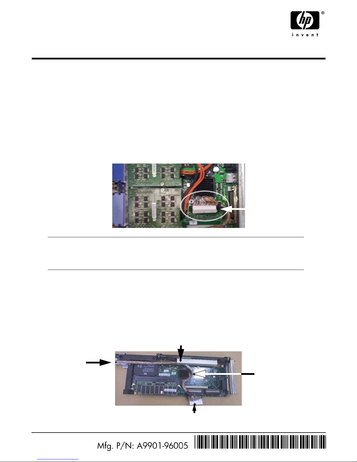
1. Disconnect the SCSI cable from the Channel A connector on the system board by pulling on the cable release strap.
See figure 1.
Figure 1. SCSI Channel A Connector on System Board
2. Remove the PCI cage from the server.
3. Remove any accessory card installed in PCI slot 2 (half-length slot).
4. Install the Smart Array PCI-X RAID card (A9890A) in PCI slot 1 (full-length slot).
5. Orient the PCI cage with the installed PCI-X RAID card component-side-up allowing routing of the SCSI cable.
See figure 2.
Figure 2. Cable Routing on Smart Array Card and PCI Cage
NOTE If an optional management processor card is installed in the server, follow the
instructions provided in the hp integrity rx1600 Operation and Maintenance Guide to
remove the card, allowing access to the Channel A connector. Reinstall the card after the
SCSI cable has been disconnected.
Channel A
connector
Around heatsink
Exit parallel to
connector
Channel A1
Under slot 2 connector
Page 2
2
6. Attach the SCSI Channel A connector (previously removed from the system board connector) to the A1 Channel of
the PCI-X RAID card.
7. Route the SCSI cable around the heatsink on the PCI-X RAID card and under the edge of the PCI slot 2 connector.
See figure 2.
8. Continue routing the cable parallel to the connector edge of the PCI cage.
9. Reinstall any accessory card previously removed from PCI slot 2.
10. Install the PCI cage into the server chassis.
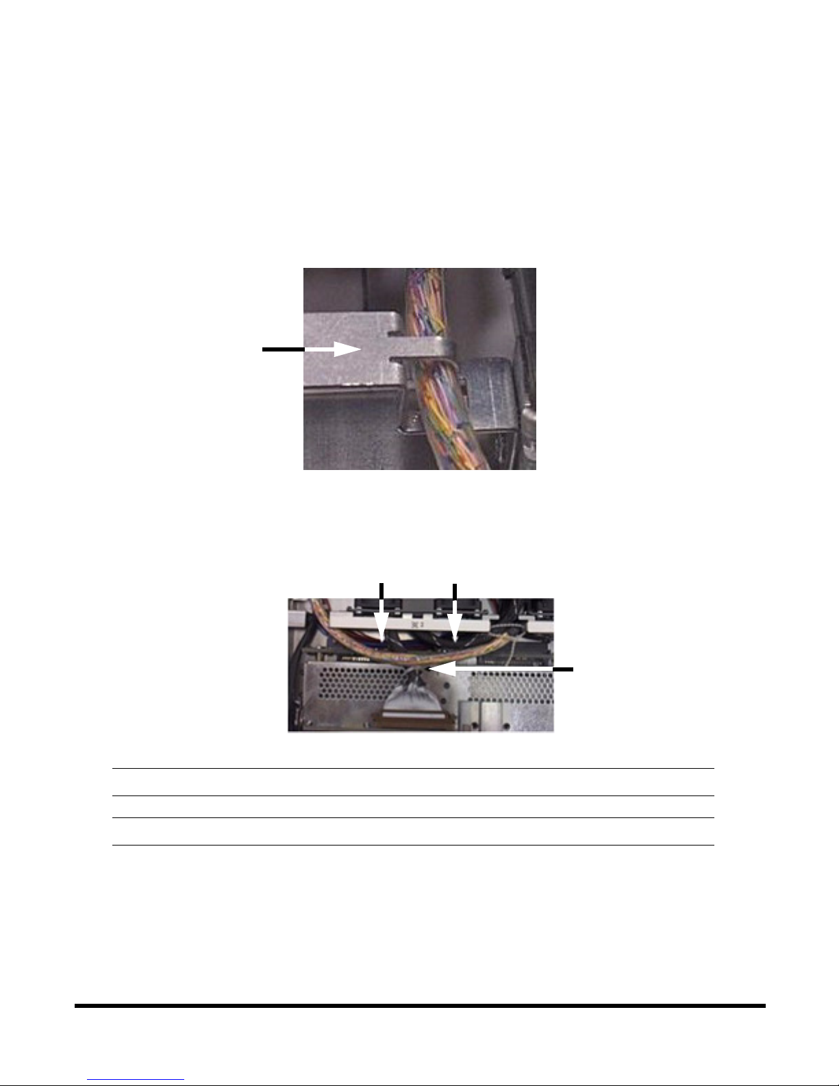
11. Route the SCSI cable under the power supply bracket as shown in figure 3.
Figure 3. Route Cable under Power Supply Bracket
12. Route the SCSI cable through the access slot of the fan assembly to the connector on the SCSI backplane.
See figure 4.
Figure 4. Cable Routing at SCSI Cage
13. Complete the installation by following the instructions provided in the hp integrity rx1600 Operation and
Maintenance Guide for closing up the server, installing in a rack, and powering-up. To enable RAID refer to the
A9890A documentation.
NOTE The SCSI cable should be routed over the IDE cable if the IDE cable is present.
CAUTION Do not block the airflow of the chassis fans. Reduced airflow may cause overheating.
Power Supply
Bracket
Route over IDE
cable (if present)
Do not block fans
 Loading...