

Page 1

HP Storage SAN Visibility 6.0 User Guide
Abstract
This document describes how to use the HP Storage SAN Visibility user interface to review the topology and inventory in a
complex Storage Area Network (SAN) environment. This document is intended for users and HP authorized service providers
who use the HP Storage SAN Visibility software to obtain SAN analysis reports.
HP Part Number: 712618-001
Published: January 2013
Edition: Second
Page 2

© Copyright 2006, 2013 Hewlett-Packard Development Company, L.P.
Confidential computer software. Valid license from HP required for possession, use or copying. Consistent with FAR 12.211 and 12.212, Commercial
Computer Software, Computer Software Documentation, and Technical Data for Commercial Items are licensed to the U.S. Government under
vendor's standard commercial license.
The information contained herein is subject to change without notice. The only warranties for HP products and services are set forth in the express
warranty statements accompanying such products and services. Nothing herein should be construed as constituting an additional warranty. HP shall
not be liable for technical or editorial errors or omissions contained herein.
Intel and Pentium are trademarks or registered trademarks of Intel Corporation or its subsidiaries in the United States and other countries.
Microsoft, Windows, Windows XP, and Windows NT are U.S. registered trademarks of Microsoft Corporation.
Java is a registered trademark of Oracle and/or its affiliates.
Page 3

Contents
1 Overview..................................................................................................6
HP Storage SAN Visibility package contents................................................................................7
Hardware and software requirements..........................................................................................7
2 Install, repair, and remove SAN Visibility.......................................................9
Supported Operating Systems....................................................................................................9
Installer prerequisites.................................................................................................................9
Installing/Updating SAN Visibility..............................................................................................9
Repair SAN Visibility..............................................................................................................10
Removing SAN Visibility..........................................................................................................11
3 Using SAN Visibility.................................................................................12
SAN Visibility GUI..................................................................................................................12
SAN Visibility menus..........................................................................................................13
Using SAN Visibility...............................................................................................................14
Accessing the SAN Visibility GUI.........................................................................................14
Specifying SAN details.......................................................................................................15
Adding SAN details......................................................................................................15
Supporting switch details....................................................................................................16
Adding a switch............................................................................................................17
Modifying switch details.................................................................................................18
Removing a switch.........................................................................................................18
Removing a component group........................................................................................19
Renaming a component group........................................................................................19
Clear All a component group..........................................................................................20
Specifying host details........................................................................................................21
Supported operating systems..........................................................................................22
Host discovery interfaces................................................................................................22
Server configurations.....................................................................................................22
Discovering hosts..........................................................................................................23
Adding hosts................................................................................................................23
Modifying login details of a host ....................................................................................23
Specifying customer details.................................................................................................24
Adding contact details...................................................................................................24
Specifying advanced settings (optional)................................................................................25
Specifying HBA-Host map details (optional)......................................................................25
Importing HBA-Host map files.....................................................................................25
Creating HBA-Host map files......................................................................................26
Specifying FICON switch details (optional).......................................................................27
Loading IOCP files....................................................................................................27
Removing IOCP files.................................................................................................27
Specifying type of SAN components to be displayed in the processed report (optional)..........28
Customizing SAN device labels to be displayed in the topology diagrams (optional).............30
Checking compatibility between different SAN components................................................32
Initiating data collection......................................................................................................35
Data collection methods......................................................................................................37
SNMP based data collection..........................................................................................37
SMI-Agent based data collection (for Brocade switch)........................................................37
Sending raw data file to HP................................................................................................38
Manually emailing raw data files to HP............................................................................38
Enabling auto emailing of raw data................................................................................39
EVA to 3PAR Storage Migration......................................................................................40
Contents 3
Page 4

Viewing raw data.........................................................................................................41
Determining the SMTP server IP address...........................................................................42
Viewing reports.................................................................................................................43
Comparing SAN................................................................................................................45
Saving the current configuration file......................................................................................46
Opening an existing configuration file..................................................................................47
Exiting from SAN Visibility..................................................................................................47
4 Support and other resources......................................................................48
Contacting HP........................................................................................................................48
Subscription service............................................................................................................48
Related information.................................................................................................................48
Documents........................................................................................................................48
Websites..........................................................................................................................48
Documentation feedback.........................................................................................................48
Product feedback....................................................................................................................49
Typographic conventions.........................................................................................................49
A DCOM configuration................................................................................50
B Troubleshooting........................................................................................52
Network connectivity issues......................................................................................................52
SNMP access failures..............................................................................................................52
SMI-S Access failures..............................................................................................................53
Changing SNMP proxy settings for HP Storage 8/20q and QLogic FC switches.............................53
C Error codes.............................................................................................54
Troubleshooting the error codes................................................................................................54
Glossary....................................................................................................58
4 Contents
Page 5

Figures
1 WMI Mapper dialog box.................................................................................................10
2 SAN Visibility welcome screen...........................................................................................12
3 SAN Visibility GUI...........................................................................................................13
4 SAN Settings window.......................................................................................................15
5 Switch Settings window....................................................................................................16
6 Brocade AG mode switch example.....................................................................................18
7 Removing switch..............................................................................................................18
8 Removing component group..............................................................................................19
9 Renaming component group..............................................................................................20
10 Clear All component group...............................................................................................21
11 Host Settings window.......................................................................................................21
12 Customer Details window..................................................................................................24
13 Specifying Advanced Settings window................................................................................25
14 HBA-Host map details window...........................................................................................26
15 IOCP files window...........................................................................................................27
16 Filter SAN components window.........................................................................................28
17 Filtering host and HBA details............................................................................................29
18 Filtering storage device details...........................................................................................29
19 Filtering virtual machine details..........................................................................................30
20 Customize topology window..............................................................................................31
21 Customize topology label window......................................................................................32
22 Compatibility Check window.............................................................................................33
23 Data Collection Window..................................................................................................35
24 Schedule Data Collection..................................................................................................36
25 CIMOM server setting window..........................................................................................38
26 SMTP Server details.........................................................................................................40
27 EVA to 3PAR StoreServ Storage Migration screen.................................................................41
28 Raw Data window...........................................................................................................42
29 Determining SMTP server details........................................................................................42
30 Processed report..............................................................................................................45
31 SAN comparison details...................................................................................................46
Tables
1 Hardware requirements.......................................................................................................8
2 SAN Visibility file menus...................................................................................................13
3 Host discovery interfaces...................................................................................................22
4 SDG Rules......................................................................................................................34
5 Document conventions......................................................................................................49
6 Error codes and troubleshooting........................................................................................54
Examples
1 Filtering host and HBA details in the processed report...........................................................29
2 Filtering storage device details in the processed report..........................................................29
3 Filtering virtual machine details in the processed report.........................................................30
4 Customizing storage device labels in the processed report.....................................................32
Page 6

1 Overview
HP Storage SAN Visibility provides a quick and easy way to review the topology and inventory
in a complex Storage Area Network (SAN) environment.
HP Storage SAN Visibility offers the following features:
• Provides an intuitive, simple, and easy to use graphical user interface (GUI).
• Collects SAN information, such as Fibre Channel (FC) switch details, host details, Host Bus
Adaptor (HBA) details, and Storage Array Connectivity information, by logging in to the FC
switches and the hosts.
• Sends raw data collected by SAN Visibility to HP (sent automatically by the SAN Visibility
software or sent manually). A processed report is generated on receipt of the data file.
• Sends processed reports containing SAN topology diagram, device inventory, high level SAN
summary, HBA-Host mapping details, analysis, and recommendations in HTML or Microsoft
Excel format.
• Allows data collection from the FICON enabled switches.
• Provides report on FICON supported devices in your SAN using IOCP file.
• Supports data collection from NPIV configured switches.
• Supports data collection from switches configured with Internet Protocol version 6 (IPv6)
addresses.
• Provides an option to filter the type of SAN components you want to view in your processed
report.
• Provides an option to customize the SAN device labels that you want to view in the processed
report (topology diagram).
• Simplifies initial SAN implementation and helps reduce SAN infrastructure cost and complexity.
• Provides an option to compare SANs and generate compared reports.
• Provides an option schedule data on a daily, weekly, or monthly basis.
• Provides an option to adjust the size of the GUI according to your preference.
• Supports physical host discovery of HP-UX, RHEL, SuSE, HyperV, VMware ESX, and Microsoft
Windows. Also supports virtualization by discovering virtual machines associated with HyperV
and VMware ESX.
• Detects host operating system details and the details of the HBA attached to the host.
• Provides firmware recommendations for Storage Devices and FC Switches.
• Check for SDG Fabric non-adherence run through captured SAN information and tries
analyzing it for any potential SDG non-adherence and generate recommendations in the
processed report based on the output of the non-adherence check.
SAN Visibility 6.0 features
• Added EVA-3PAR StoreServ Storage Migration recommendation feature.
• 3PAR StoreServ Storage Array recommendation and compatibility support for F200, F400,
• Added host discovery support for :
6 Overview
T400, T800, 10400, 10800, 7200 and 7400 models.
ESX/ESXi 4.1, ESX/ESXi 5.0 and ESX/ESXi 5.1◦
◦ Windows 2008 R2
Page 7

This chapter addresses the following topics:
• “HP Storage SAN Visibility package contents” (page 7)
• “Hardware and software requirements” (page 7)
HP Storage SAN Visibility package contents
Following are the components of the HP Storage SAN Visibility bundle:
• HP Storage SAN Visibility installer (SANVisibility_Setup.exe)
• Product documentation
• Licenses
Hardware and software requirements
This section discusses the hardware and software requirements for installing HP Storage SAN
Visibility.
• Software
To use HP Storage SAN Visibility, following are the necessary applications that need to be
installed on a host where HP Storage SAN Visibility is installed:
Installation
◦ Java 2 Runtime Environment (JRE) v1.5 or v1.6.
Data Collection
◦ Windows Remote Management version 2.0 (WinRM)
Run following commands to complete the winrm setup
1. Open command prompt.
2. Execute winrm quickconfig
– If the system prompts to start the WinRM service, press 'y' followed by the
'enter'
3. Execute “winrm set winrm/config/Service/auth @{Basic="true"}”
4. Execute “winrm set winrm/config/Service
@{AllowUnencrypted="true"}”
– Brocade SMI Agent (120.6.0 a) installed for SMI-S based data collection. For
more information, see the SMI-Agent user guide.
NOTE: Brocade SMI-Agent installation is not mandatory for SAN Visibility data collection. If
Brocade SMI-Agent is not installed, then the collection takes place through SNMP (and Brocade
APIs). For more information on data collection methods, see “Data collection methods” (page 37).
Viewing Report
• Internet Explorer 8 or Internet Explorer 9
• Microsoft Excel viewer
• Microsoft Visio viewer
Table 1 (page 8) lists the hardware requirements.
HP Storage SAN Visibility package contents 7
Page 8

Table 1 Hardware requirements
RecommendedMinimum
Pentium III processor 128 MB RAM 10 Base-T Ethernet port
Standard LAN connectivity with target FC switches and
hosts
Pentium IV processor 256 MB RAM 100 Base-T Ethernet
port
8 Overview
Page 9

2 Install, repair, and remove SAN Visibility
Supported Operating Systems
Following are the prerequisites to install and run HP Storage SAN Visibility:
• Microsoft Windows system with any of the following operating systems:
◦ Microsoft Windows Server 2003 Standard or Enterprise edition with Service Pack 2
◦ Microsoft Windows XP Professional edition with Service Pack 2
◦ Microsoft Windows Server 2008 Enterprise Edition with Service Pack 2
◦ Microsoft Windows 7
◦ Microsoft Windows 2008 R2
◦ Microsoft Windows Vista Enterprise Edition with Service Pack 2
NOTE: For installing SAN Visibility on a system running on Microsoft Vista, do one of
the following:
– Disable User Account Control (UAC) on the system. For more information on how to
disable UAC, see http://technet.microsoft.com/en-us/library/cc709691.aspx.
Installer prerequisites
To install HP Storage SAN Visibility:
1. WMI Mapper must not be installed before installing HP Storage SAN Visibility. If WMI Mapper
is installed before installing HP Storage SAN Visibility then, HP Storage SAN Visibility's
installation does not proceed and displays the following message and aborts the installation:
The Installer found an instance of WMI Mapper running on this
machine. Installing HP Storage SAN Visibility may affect other HP’s
product. Please install HP Storage SAN Visibility on machine where
WMI Mapper is not installed.
2. 32-bit JRE, v1.5 or v1.6 is required to install HP Storage SAN Visibility.
For example, If JRE v1.6 and v1.7 are installed in the machine, v1.7 is considered as the
latest version. Since, JRE v1.7 is not supported by HP Storage SAN Visibility, the installer
throws the following error:
JRE was not found.
Installing/Updating SAN Visibility
To install/upgrade HP Storage SAN Visibility, complete the following steps:
1. Download HP Storage SAN Visibility package from the following website:
http://h18006.www1.hp.com/storage/networking/sansolutions.html
2. Select a folder (for example, C:\temp) to save the HP Storage SAN Visibility install package.
3. Run SANVisibility_Setup.exe, and follow the steps to install HP Storage SAN Visibility
files.
Supported Operating Systems 9
Page 10

NOTE:
• To Upgrade to SAN Visibility , select Next in the Welcome to the InstallShield of the HP
Storage SAN Visibility dialog box.
• SAN Visibility user must be installed with the administrator privileges.
• Installing SAN Visibility installs WMI mapper internally.
4. Review and accept the license agreement.
By default, the HP Storage SAN Visibility files and documentation are installed in the following
folder:
<Install_Dir>\Hewlett-Packard\HP SAN Visibility
A message is displayed on completion of the SAN Visibility software installation.
NOTE: 32-bit JRE, v1.5 or v1.6 is required to install HP Storage SAN Visibility.
5. A dialog box is displayed if the default WMI Mapper port is busy as shown in Figure 1
(page 10).
Figure 1 WMI Mapper dialog box
NOTE: HP Storage SAN Visibility software, collects HOST HBA information using the WMI
classes. WMI HBA classes are not packaged along with the Windows 2003 OS base version.
The corresponding mof file must be installed manually. To execute this, download the latest
installer fcinfo.exe from the Microsoft website, and complete the installation process. The
higher versions of Windows OS have the mof file installed by default.
Repair SAN Visibility
To repair HP Storage SAN Visibility software:
1. Select Start > Settings > Control Panel > Add or Remove Programs.
10 Install, repair, and remove SAN Visibility
Page 11

2. Select HP Storage SAN Visibility from the list of Currently Installed Programs.
3. Click Change, and select Repair and follow the steps to repair the program.
NOTE: WMI Mapper cannot be repaired from Add/Remove programs directly . At the time of
repairing SAN Visibility, WMI Mapper is also repaired internally.
Removing SAN Visibility
To remove the HP Storage SAN Visibility software, complete the following steps:
1. Select Start > Settings > Control Panel > Add or Remove Programs.
2. Select HP Storage SAN Visibility from the list of Currently Installed Programs.
NOTE: Before removing HP Storage SAN Visibility from your system, ensure that you close
all the applications.
3. Click Change, and select Remove and follow the steps to remove the program.
WARNING! While un-installing, SAN Visibility uninstalls the WMI Mapper installed by the
SAN Visibility installation.
4. A message is displayed confirming the successful removal of the SAN Visibility software.
NOTE: Removal of SAN Visibility does not remove the existing SAN Visibility reports and profiles
from the installation directory.
Removing SAN Visibility 11
Page 12

3 Using SAN Visibility
This chapter addresses the following topics:
• “SAN Visibility GUI” (page 12)
• “Using SAN Visibility” (page 14)
Following is a brief overview of using HP Storage SAN Visibility:
1. Specify the SAN details.
2. Specify the switch details.
3. Specify the host details.
4. Specify your contact information.
5. Run data collection.
6. Email the data collected (with .hp extension) to HP at: “SAN_Visibility@hp.com” for analysis.
HP sends back the processed report consisting of SAN topology diagram, SAN inventory,
EVA to 3PAR StoreServ Storage migration and HP hardware recommendations by email.
SAN Visibility GUI
Launch the HP Storage SAN Visibility software by double-clicking the SAN Visibility shortcut icon
on the desktop. The HP Storage SAN Visibility welcome screen is displayed, as shown in
Figure 2 (page 12).
Figure 2 SAN Visibility welcome screen
Click OK to view the SAN Visibility GUI.
Following are the display areas in the SAN Visibility GUI, as shown in Figure 3 (page 13):
• A — Navigation area
• B — Main display area
12 Using SAN Visibility
Page 13

• C — SAN explorer area
• D — Message area
• E — up and down arrow button available in the message area to expand it for a better view
of the messages
Figure 3 SAN Visibility GUI
SAN Visibility menus
Table 2 (page 13) lists the SAN Visibility menu items.
Table 2 SAN Visibility file menus
Menu:
Select...To...
File > NewCreate a new SAN Visibility session
File > OpenOpen an existing SAN Visibility profile
File > SaveSave the SAN Visibility profile
File > Save As...Save the SAN Visibility profile with name of your choice
File > ExitExit from SAN Visibility software
View > Raw DataView the raw data that is sent to HP for processing
View > Packaged Data LocationView the packaged data location
View > CIMOM Server SettingsView the CIMOM server settings
Help > SAN Visibility HelpAccess SAN Visibility help
Help > SAN Visibility FAQView SAN Visibility frequently asked questions (FAQ)
Help > Sample Processed ReportView sample SAN Visibility processed report
SAN Visibility GUI 13
Page 14

Table 2 SAN Visibility file menus (continued)
Menu:
Select...To...
Help > SAN Visibility On WebAccess SAN Visibility home page
Help > HP Support Engineer SettingsEnable Migration Recommendation
Help > Welcome ScreenView the welcome screen
Help > About SAN VisibilityAccess information about SAN Visibility
Send the logs
Compare SAN
Using SAN Visibility
This section describes how to use SAN Visibility software and discusses the following topics:
• “Accessing the SAN Visibility GUI” (page 14)
• Specifying SAN details
• Specifying switch details
• “Specifying host details” (page 21)
• Specifying customer details
• “Specifying advanced settings (optional)” (page 25)
• Initiating data collection
Help > Send Logs >
Select one of the following options:
• Place on Desktop: Places the log file on the desktop.
• Send without Query: Sends the log file without an option
to provide additional information through e-mail.
• Send with Query: Sends the log file with an option to
provide additional information through e-mail.
SAN Comparison > Compare SAN
For more information, see “Comparing SAN” (page 45)
• “EVA to 3PAR Storage Migration”
• “Sending raw data file to HP” (page 38)
• “Enabling auto emailing of raw data” (page 39)
• Determining the SMTP server IP address
• Viewing reports
• “Comparing SAN” (page 45)
• Saving the current configuration file
• Opening an existing configuration file
• Exiting from SAN Visibility
Accessing the SAN Visibility GUI
To access the SAN Visibility GUI, complete the following steps:
1. Double-click the HP Storage SAN Visibility shortcut icon on the desktop. The SAN Visibility
welcome screen is displayed.
2. Go to Start>Programs>Hewlett-Packard>HP Storage SAN Visibility folder. Click HP Storage
SAN Visibility. The SAN Visibility welcome screen is displayed.
3. Click OK to view the SAN Settings window.
14 Using SAN Visibility
Page 15

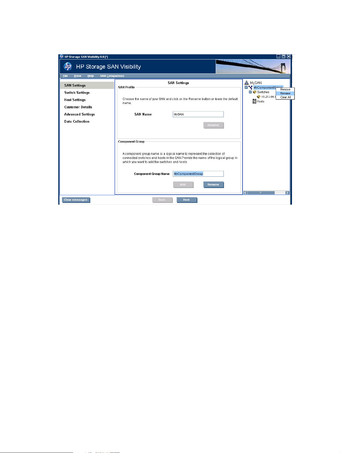
Specifying SAN details
The SAN Settings window displays SAN details. It enables you to add and modify a SAN group.
Figure 4 (page 15) shows the SAN Settings window.
Figure 4 SAN Settings window
Adding SAN details
To add SAN details:
1. Click SAN Settings from the navigation area. The SAN Settings window is displayed in the
main display area. The default SAN name, MySAN, is displayed in the SAN Name box, as
shown in Figure 4 (page 15).
If you want to rename the SAN, then enter the name of the SAN that you want to scan in the
SAN Name box.
2. Click Rename.
3. The Confirmation window is displayed with the following message:
Do you want to rename the Profile "MySAN" with XYZ?
• Click Yes, to rename the SAN name.
• Click No, to cancel and not rename.
4. Once the renaming is confirmed, the SAN name appears in the SAN explorer area.
NOTE: Raw data file generated by SAN Visibility uses the SAN name. For example, if the SAN
Name is MYHP, the raw report file is generated as MYHP.hp at the <Install_Dir>\reports
directory.
A Component Group Name is a logical name to represent the collection of connected switches
and hosts in the SAN.
Using SAN Visibility 15
Page 16

To enter the Component Group Name:
1. Enter the name of your component group in the Component Group Name box. The default
component group name, MyComponentGroup, is displayed in the Component Group Name
box, as shown in Figure 4 (page 15).
2. Click Add. The component group name appears in the SAN explorer area under the SAN
name.
NOTE: To add multiple component groups under the SAN, repeat the steps 1-2.
3. Click Rename, to rename the existing Component Group name accordingly:
1. Select a Component Group Name from the SAN explorer area.
2. Replace the name in the Component Group Name box.
3. Click Rename.
4. The Confirmation window is displayed with the following message:
Do you want to rename the Component Group name "MyComponentGroup"
to XYZ?
• Click Yes, to rename the Component Group name.
• Click No, to cancel and not rename.
4. Click Next to enter the switch details.
Supporting switch details
The Switch Settings window enables you to search, add, and modify all the connected switches.
Figure 5 (page 16) shows the Switch Settings window.
Figure 5 Switch Settings window
16 Using SAN Visibility
Page 17

Adding a switch
To add a switch:
1. Click Switch Settings from the navigation area. The Switch Settings window is displayed in
the main display area.
2. Select one of the following options from the main display area:
• IP Address: If you know the IP address of the switch to scan.
• Subnet: If you want to find all the valid switches in a given range of IP addresses.
Enter the IP address of the switch to be scanned in the IP Address box, as shown in
a.
Figure 5 (page 16).
b. Select Discover connected switches check box if you want to discover all the connected
switches.
c. Enter the access information, as required, to initiate data capture for the selected
switch.
NOTE: The Brocade switch requires login and password.
d. Select a component group from the Select Component Group drop-down list.
e. Click Add. The switch becomes a part of the named group if it is a valid and
supported switch.
f. Repeat steps a-e if you want to add multiple switches.
a. Enter the starting IP address in the Start at IP Address box.
b. Enter the limiting IP address in the Stop at IP Address box.
c. Enter the access information, as required, to initiate data capture for the selected
switch.
NOTE: The Brocade switch requires login and password.
d. Click Discover Switch to discover valid switches.
NOTE: SAN Visibility queries each IP address in the specified range to determine
if it is a valid and supported switch. Time taken depends on the IP address range
given. During host discovery, a subnet scan will timeout after 30 minutes.
e. Select a component group from the Select Component Group drop-down list, and
click Add. The selected switch is added under the switch node of the selected
component group.
f. Repeat steps a-e if you want to add multiple switches.
3. Click Next to enter the customer details.
The detected switches are added to the specified component group, and the details are
displayed in the message area.
For a Brocade AG (Access Gateway mode) switch in your SAN environment, the switch name is
updated with “Access Gateway Mode” information in the SAN explorer area to specifically identify
that the switch is running in AG mode. Figure 6 (page 18) displays the Brocade AG mode switch
example.
Using SAN Visibility 17
Page 18

Figure 6 Brocade AG mode switch example
Modifying switch details
To modify switch details:
1. Select the switch you want to modify from the SAN explorer area to view its details.
2. Modify the switch details as required.
3. Click Update to save the modified switch details.
Removing a switch
To remove a switch from the component group:
1. Select the switch you want to remove from the SAN explorer area.
2. Right-click and select Remove from the pop-up menu, as shown in Figure 7 (page 18).
3. The Delete Confirmation window is displayed with the following message:
Do you want to delete the XYZ switch?
• Click Yes, to delete the switch.
• Click No, to cancel the deletion.
The switch is removed from the component group.
Figure 7 Removing switch
18 Using SAN Visibility
Page 19

Removing a component group
To remove a component group from the SAN:
1. Select the component group that you want to remove from the SAN explorer area.
2. Right-click and select Remove from the pop-up menu, as shown in Figure 8 (page 19).
3. The Delete Confirmation window is displayed with the following message:
Do you want to delete the XYZComponentGroup?
• Click Yes, to delete the ComponentGroup.
• Click No to cancel the deletion.
The component group is removed from the SAN.
CAUTION: Removing a component group removes all the switches attached to that group.
Figure 8 Removing component group
Renaming a component group
To rename a component group:
1. Select the component group that you want to rename from the SAN explorer area.
2. Right-click and select Rename from the pop-up menu, as shown in Figure 9 (page 20).
3. Enter the component group name in the Component Group Name box in the main display
area.
Using SAN Visibility 19
Page 20
4. Click Rename.
The component group is renamed.
Figure 9 Renaming component group
Clear All a component group
You can use the Clear all option is used to collapse the components under the respective Component
Group.
1. Select the component group that you want to collapse.
2. Right-click and select Clear All from the pop-up menu, as shown in Figure 10: Clear All
component group.
20 Using SAN Visibility
Page 21
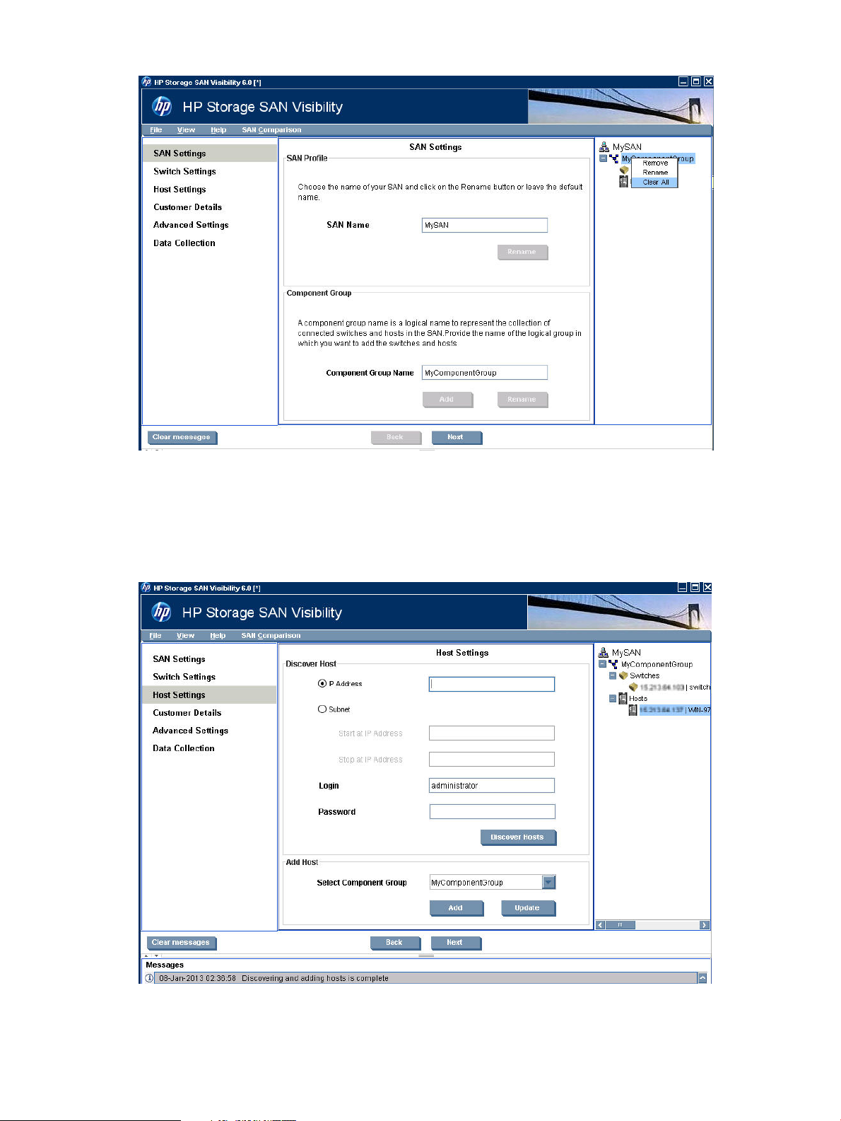
Figure 10 Clear All component group
Specifying host details
The Host Settings window enables you to discover and add hosts in a SAN environment.
Figure 11 (page 21) displays the Host Settings window.
Figure 11 Host Settings window
Using SAN Visibility 21
Page 22

Supported operating systems
The following operating systems support host discovery:
OS VersionOS NameOS TypeSr. No:
11.23,11.31HPUXPhysical1
3.0, 3.5, 4.0,4.1ESXVirtual2
3.5, 4.0,4.1,5.0, 5.1ESXiVirtual3
Hyper VVirtual4
5, 6Red Hat Enterprise LinuxPhysical5
9, 10, 11SUSE LinuxPhysical6
Physical7
Physical10
Host discovery interfaces
Table 3 (page 22) describes the interfaces used for host discovery and data collection:
Table 3 Host discovery interfaces
Server configurations
Microsoft Windows
Do the following:
Service Pack 2Microsoft Windows 2003
Standard or Enterprise edition
Microsoft Windows 2003 R2Physical8
Microsoft Windows Server 2008Physical9
Microsoft Windows Server 2008
R2
Operating systemInterface
ESX, HP-UXWBEM
ESX, Linux, and HP-UXSSH
Windows (including HyperV)WMI
• The WMI service is running and it includes the Windows installer provider component.
WMI configuration
• If you are an Administrator, then do not make any changes.
• If you are a non-administrator, then remote access, remote launch, and remote activation
permissions are required. Provide permissions for everyone in the group.
To provide permissions for everyone in the group:
1. In the Control Panel, double-click Administrative Tools.
2. In the Administrative Tools window, double-click Component Services.
3. Expand Computers, and right-click My Computer, and then select Properties.
4. In the COM Security tab, under Access Permissions click Edit Limits and provide Remote
Access permissions for everyone.
5. In the COM Security tab, under Launch and Activation Permissions click Edit Limits, and
provide Remote Launch and Remote Activation permissions for everyone.
If the above steps do not work, see “DCOM configuration” (page 50).
22 Using SAN Visibility
Page 23

ESX, HP-UX, Linux
Ensure that SSH is running and password authentication is enabled. To enable password
authentication, set passwordAuthentication.in /etc/ssh/sshd_config file to yes and
restart the ssh service.
NOTE: In the ESX environment, it is mandatory to use the above mentioned configurations for
3.0 ,3.5 and 4.0 OS versions.
ESX, HP-UX
Ensure the following:
• The CIM server is running on the server.
• The Wbem provider modules for the Operating system, computer system, and the FC HBA is
registered with the CIM server and access is enabled.
• The Wbem service or the CIMServer is configured for remote access for a given user.
NOTE: In the ESX environment, it is mandatory to use the above mentioned configurations
for 3.0 ,3.5 and 4.0 OS versions.
Discovering hosts
To discover hosts:
1. Select Host Settings from the navigation pane.
The Host Settings window is displayed.
2. Under Discover Host, select one of the following options:
3. Enter the access information, as required, to initiate host discovery.
4. Click Discover Hosts to discover the physical hosts and the associated virtual machines.
Adding hosts
To add a host:
1. Under Add Host, select a component group from the Select Component Group list.
2. Click Add to add the selected host.
• IP Address: Enter the IP address of the host in the IP Address field.
• Subnet: If you want to discover hosts for a range of IP addresses:
◦ Enter the starting IP address in the Start at IP Address field.
◦ Enter the limiting IP address in the Stop at IP Address field.
NOTE: For Subnet, the host login details of all the hosts in a subnet must match the login
details specified in the Host Settings screen.
Port 6001 is required for Host discovery in SAN Visibility. The same can be enabled in
firewall.
The host is added under the host node of the selected component group.
Modifying login details of a host
To modify login details of a host:
1. Select a host from the Select Component Group list.
2. Modify the login details as required.
3. Click Update.
4. Click Next to enter the Customer details.
Using SAN Visibility 23
Page 24

Specifying customer details
The Customer Details window enables you to enter your contact information, SMTP server details,
and preferences for receiving additional HP product information. Figure 12 (page 24) displays
the Customer Details window.
Figure 12 Customer Details window
Adding contact details
To add your contact details:
1. Click Customer Details from the navigation area. Customer Details window appears in the
main display area.
2. Enter your Name and E-Mail, which is mandatory, in the Customer Details window.
NOTE: Ensure that the email address you enter is accurate. SAN Visibility reports are sent
to this email address.
SAN Visibility enables you to enter multiple email address in the E-mail box. The SAN Visibility
reports are sent to all the email addresses provided.
Use semicolon (;) between the email addresses to enter multiple email address.
For example: xyz@first.com; abc@second.com; pqr@third.com
1. Select Automatically e-mail the collected raw data on completion check box. For more
information, see “Enabling auto emailing of raw data” (page 39).
2. Enter your SMTP server name or select it from the SMTP Server dropdown box. For more
information, see Determining the SMTP server IP address.
3. Select the appropriate option if you want to receive additional information (such as special
offers, new product information, events, service or support information) from HP.
4. Click Next to go to the Advanced Settings window. Specifying Advanced Settings details is
optional.
5. Click Next to initiate the data collection.
24 Using SAN Visibility
Page 25

Specifying advanced settings (optional)
The Advanced Settings window enables you to do the following tasks:
• “Specifying HBA-Host map details (optional)” (page 25)
• “Specifying FICON switch details (optional)” (page 27)
• “Specifying type of SAN components to be displayed in the processed report (optional)” (page
28)
• “Customizing SAN device labels to be displayed in the topology diagrams (optional)” (page
30)
• “Checking compatibility between different SAN components”
NOTE: Specifying HBA-Host map details, loading FICON switch related files, specifying SAN
components and customizing SAN device labels to be displayed in the topology diagrams are
optional. You may choose to provide these information if you want to customize the way information
is presented for your SAN in the processed report.
Figure 13 (page 25) displays the Advanced Settings window.
Figure 13 Specifying Advanced Settings window
Specifying HBA-Host map details (optional)
HBA-Host map file contains HBA-Node WWN and host mapping details. If this map file is provided
in the raw report, then the processed report maps the HBA-Node WWNs to the host names, and
the same information is displayed in the processed report.
You can create a new HBA-Host map file or you can import an existing HBA-Host map file.
HBA-Host map file can be a .csv file (comma separated file) or it can be a Fnames.conf file.
The Fnames.conf file is the HP Storage Command View EVAPerf configuration file. SAN Visibility
enables you to parse and populate the corresponding mapping entries from the .csv file.
Importing HBA-Host map files
To import a HBA-Host map file, complete the following steps:
Using SAN Visibility 25
Page 26

1. Click Advanced Settings from the navigation area of the SAN Visibility GUI. The Advanced
Settings window is displayed.
2. Click the Map HBA to Host tab.
3. Click Import File to select a HBA-Host map file.
4. Browse and select the HBA-Host map file that you want to load, and click Open.
Figure 14 (page 26) displays the HBA-map details.
NOTE: You can only load a .csv file or a Fnames.conf file.
Figure 14 HBA-Host map details window
You can also modify an imported host map file. Click Add Row to add content to the file and click
Delete Row to delete a row.
To save the modified file, click Save File. The host map file is saved as a <file_name>.csv file.
Creating HBA-Host map files
To create a HBA-Host map file, complete the following steps:
1. Click Advanced Settings from the navigation area of the SAN Visibility GUI.
2. Click the Map HBA to Host tab.
3. Click Create File.
4. Click Add Row to enter the HBA Node WWN, and Host Name details.
NOTE: To delete a row, click Delete Row.
5. Click Save File.
The created file is saved at the mentioned location.
If you want to remove the loaded HBA-Host map file, click Remove File.
Ensure that you provide the HBA-Node WWN and the host name details in the correct format.
You can also manually create the HBA-Host map file in a text editor, save it as .csv file and then
import it. For more information on importing HBA-Host map file see, “Importing HBA-Host map
files” (page 25). The format of the .csv file is shown below:
26 Using SAN Visibility
Page 27
Example: HBA-Host map file
# HBAWWN,HostName
20:00:00:00:c9:64:2a:69,Sanvishost1.xyz.com
20:00:00:00:c9:76:50:57,Sanvishost2.xyz.com
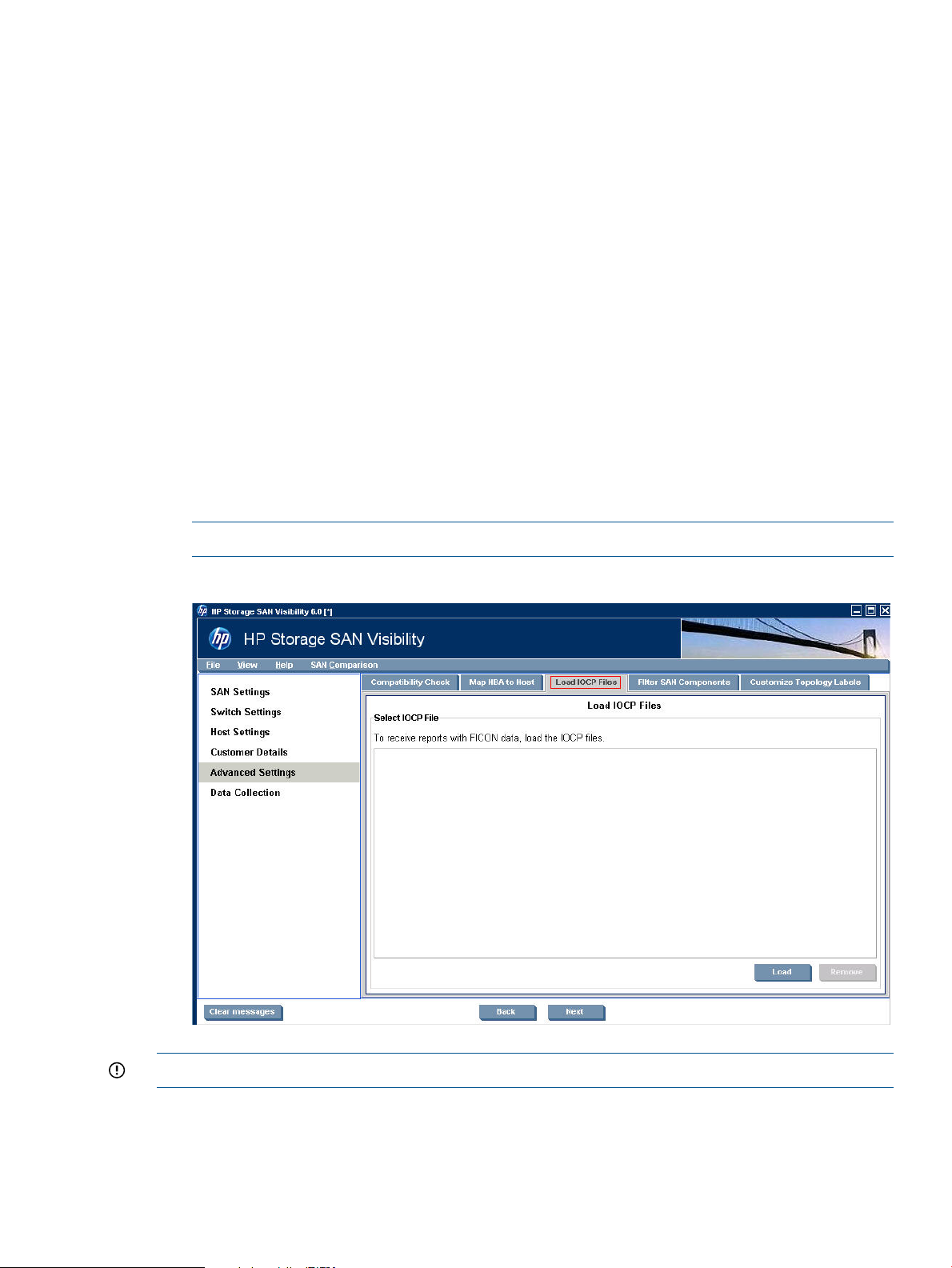
Specifying FICON switch details (optional)
HP Storage SAN Visibility 3.0 and above supports data collection from FICON enabled switches
in a SAN environment consisting of IBM mainframe servers. To receive reports on FICON supported
devices in your SAN, load the IOCP files in the text format in the SAN Visibility Advanced Settings
window. Ensure that the FICON enabled switches are discovered and added in the SAN Settings
window in order to collect data.
Loading IOCP files
The IOCP file is a text file containing connectivity details. To load an IOCP file, complete the
following steps:
1. Click Advanced Settings from the navigation area of the SAN Visibility GUI.
2. Click the Load IOCP Files tab.
3. Click Load to select an IOCP file.
4. Browse and select the IOCP file that you want to load, and click Open. Figure 15 (page 27)
displays the IOCP file details.
NOTE: The IOCP file is a .txt file.
Figure 15 IOCP files window
IMPORTANT: SAN Visibility does not generate IOCP files.
Removing IOCP files
To remove an IOCP file, complete the following steps:
1. Select the IOCP file you want to remove
Using SAN Visibility 27
Page 28

2. Click Remove.
The selected IOCP file is removed.
Specifying type of SAN components to be displayed in the processed report (optional)
HP Storage SAN Visibility provides an option to filter the type of SAN components you want to
view in your processed report.
NOTE: You can not filter a switch from the processed report. A switch can not be filtered from
the processed report as it is an integral part of the fabric and is required for SAN Visibility data
collection.
To specify the type of SAN components that you want to view in the processed report, complete
the following steps:
1. Click Advanced Settings from the navigation area of the SAN Visibility GUI.
2. Click the Filter SAN Components tab. Figure 16 (page 28) displays the filter SAN components
details.
Figure 16 Filter SAN components window
3. Select Yes if you want to receive storage device details in the processed report.
4. Select Yes if you want to receive host and HBA details in the processed report.
5. Select Yes if you want to receive virtual machine details in the processed report.
If you select No, the processed report will not contain any descriptive details for the selected SAN
component.
28 Using SAN Visibility
Page 29

Example 1 Filtering host and HBA details in the processed report
Figure 17 (page 29) shows an example of how the processed report appears if you have opted
not to display host and HBA details in the processed report. Even though your SAN environment
may contain hosts and HBAs, the processed report, including the topology diagram, will not display
the host and HBA details.
Figure 17 Filtering host and HBA details
Example 2 Filtering storage device details in the processed report
Figure 18 (page 29) shows an example of how the processed report appears if you have opted
not to display storage details in the processed report. Even though your SAN environment may
contain storage devices, the processed report, including the topology diagram, will not display
the storage details.
Figure 18 Filtering storage device details
Using SAN Visibility 29
Page 30

Example 3 Filtering virtual machine details in the processed report
Figure 19 shows an example of how the processed report appears if you have opted not to display
virtual machine details in the processed report. Even though your SAN environment may contain
virtual machines, the processed report, including the topology diagram, will not display the virtual
machine details.
Figure 19 Filtering virtual machine details
Customizing SAN device labels to be displayed in the topology diagrams (optional)
HP Storage SAN Visibility provides an option to customize the SAN device labels that you want
to view in the processed report. Only the SAN device labels that are selected will be displayed in
the SAN topology diagram.
To specify the SAN device labels that you want to view in the SAN topology diagram, complete
the following steps:
1. Click Advanced Settings from the navigation area of the SAN Visibility GUI.
2. Click the Customize Topology Labels tab. Figure 20 (page 31) displays the customize SAN
topology window.
30 Using SAN Visibility
Page 31
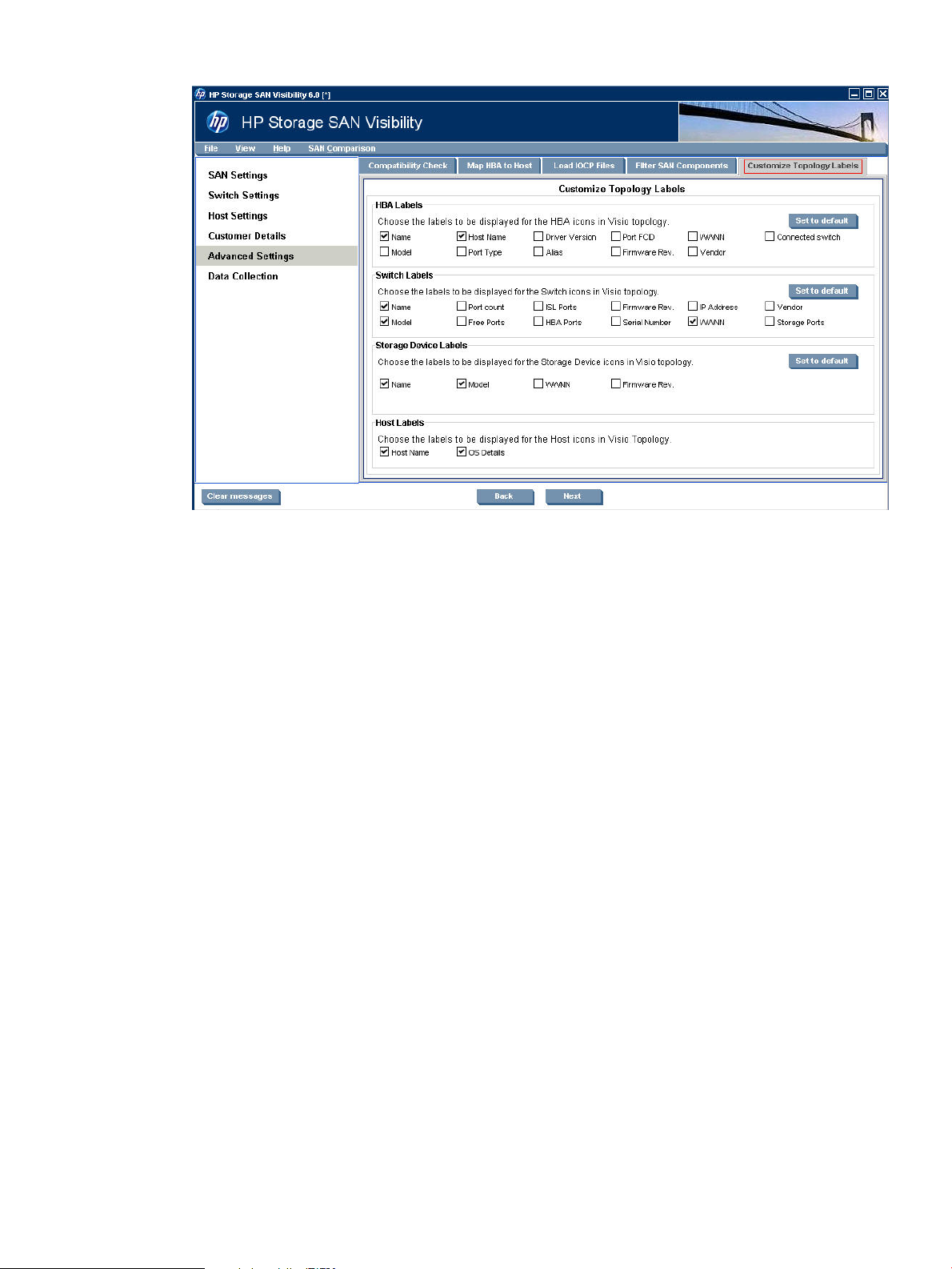
Figure 20 Customize topology window
3. Select the HBA, switch, storage, and host labels as per your preference.
The SAN topology diagram sent to you will contain the SAN component details as per your
selection.
Using SAN Visibility 31
Page 32
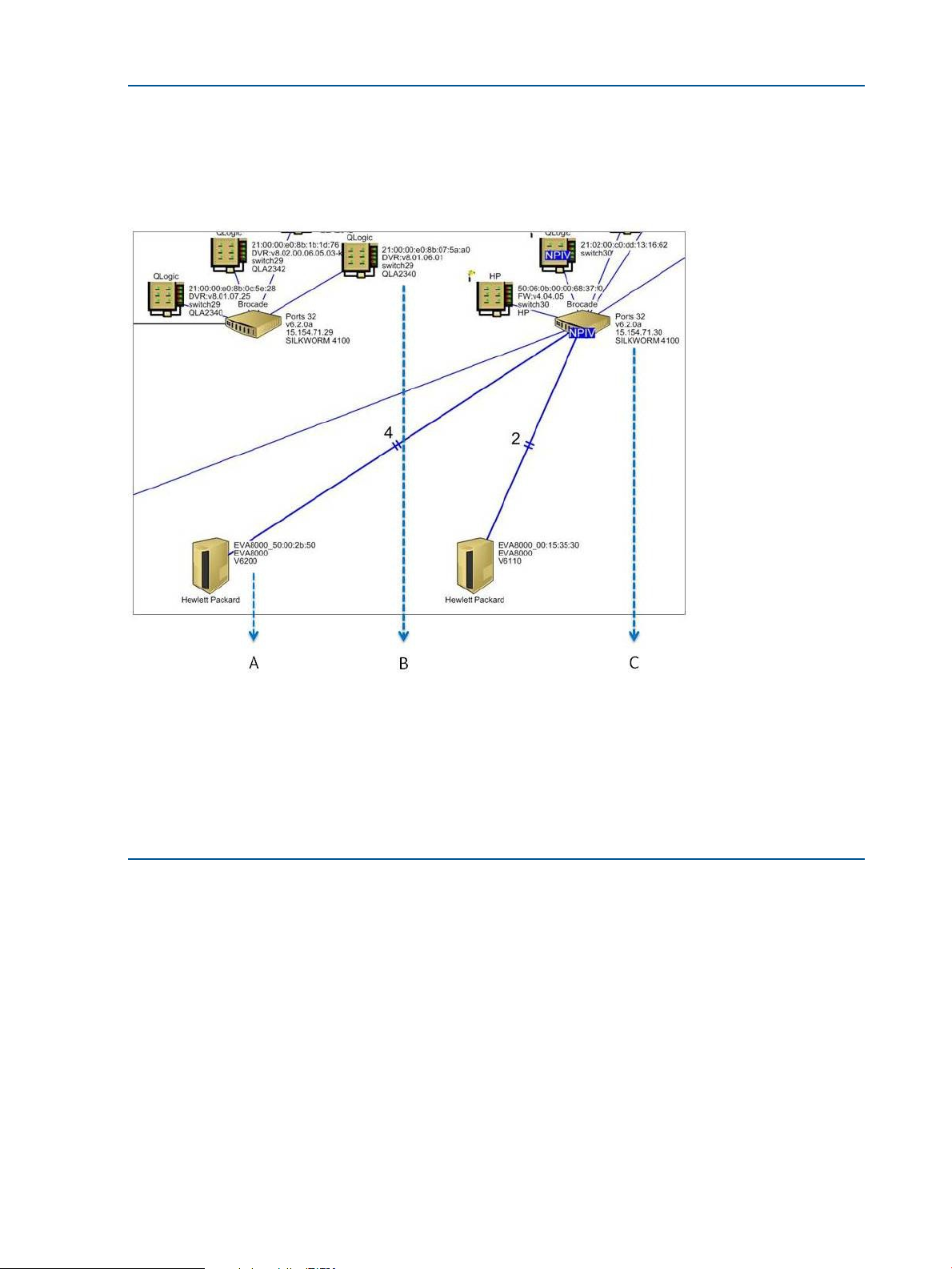
Example 4 Customizing storage device labels in the processed report
Figure 21 (page 32) shows an example of how the processed report looks like if you have opted
to view only specific SAN device labels in the processed report. Only the SAN device labels that
are selected in the Customize Topology Labels window will be displayed in the processed SAN
topology diagram.
Figure 21 Customize topology label window
A — Array details. Only the array name, model number and firmware version is displayed as selected in the SAN
Visibility GUI before data collection.
B — HBA details. Only the WWNN, driver version, connected switch and model number is displayed as selected in
the SAN Visibility GUI before data collection.
C — Switch details. Only the IP address, firmware version, number of ports and model number is displayed as selected
in the SAN Visibility GUI before data collection.
Checking compatibility between different SAN components
HP Storage SAN Visibility analyzes compatibility for the different SAN components available in
the report. It will check compatibilities between, Host and Switch, Switch and Array, Host and
Array using SDG guidelines. The guidelines and recommendations will be generated and added
in processed report.
To check the compatibility between different SAN components, complete the following steps:
1. Click Advanced Settings from the navigation area of the SAN Visibility GUI.
2. Click the Compatibility Check tab. Figure 22 (page 33) displays the Compatibility Check
window.
By default, the check boxes under the Compatibility Check tab are selected.
32 Using SAN Visibility
Page 33

Figure 22 Compatibility Check window
Using SAN Visibility 33
Page 34

3. Deselect one of the following options, if you do not want to check the compatibility between
the SAN components:
• Enable for Compatibility Analysis: This option enables you to perform a standard
compatibility analysis.
◦ The feature will use SDG guidelines and information available on SPOCK as the
source for compatibility matrix.
◦ The recommendations will be generated for HP hardware (or HP OEM hardware)
only. For devices that are not identified as HP hardware, recommendations will be
not generated.
◦ Compatibility checks will be done only for components which are available in the
sent report.
◦ If only one set of components are available in the raw report then no recommendations
will be generated (i.e. say only host information is available then no compatibility
analysis will be done. If only host and switch information is available then
compatibility analysis will be done between host and switch only).
• Enable for Fabric and Zone Analysis: This option enables you to perform fabric and zone
analysis.
◦ he analysis will be done for HP or HP OEM hardware only.
◦ The fabric analysis will be done on homogeneous fabrics only.
Table 4 SDG Rules
RuleRule TypeSl. No:
Fabric1
Fabric2
Fabric3
Fabric4
"In a fabric that contains a Brocade 4Gb SAN Switch for HP c-Class or p-Class
BladeSystem, Storage SAN Switch 4/8, 4/16, 4/32B, 4/32, 4/64, 2/32, SAN
Director 2/128, or SAN Director 4/256, Core switch addressing mode is required
on all other switches in that fabric."
In a B – Series switch maximum of seven hops (eight switches) 14 between any
two communicating devices.
"B – Series: A 2408 FCoE Converged Network Switch or DC SAN Director Switch
10/24 Blade can be a standalone switch or an edge switch in a Fibre Channel
fabric. To attach the switch to an existing Fibre Channel fabric as an edge switch,
at least one Fibre Channel port on the FCoE CN switch must be connected to a
Fibre Channel switch in the fabric (E_Port). There cannot be any other FCoE or 10
GbE CEE switches in the path to the Fibre Channel switch. "
"C – Series: A C-series FCoE CN switch can be a standalone switch or an edge
switch in a Fibre Channel fabric. To attach the switch to an existing Fibre Channel
fabric as an edge switch, at least one Fibre Channel port on the FCoE CN switch
must be connected to a Fibre Channel switch in the fabric (E_Port). There cannot
be any other FCoE or 10 GbE IEEE DCB switches in the path to the Fibre Channel
switch. For FCoE E_Port connectivity, the Fibre Channel switch minimum firmware
version is NX-OS 4.1(3)N1(1). All C-series 4 Gb/s or 8 Gb/s switch models are
supported when using the minimum firmware version. MDS switches running SANOS
3.x can be in the Fibre Channel SAN but cannot be connected directly to an FCoE
switch. "
34 Using SAN Visibility
Zone5
Zone6
Zone7
"Zone by HBA - This rule suggests that hosts with HBAs from same vendor can be
configured in same zone "
" Zone by OS - This rule suggests that hosts running same Operating System should
be configured in same zone "
"Zone by Storage - This rule suggests to define a separate zone for each storage
system family e.g. P2000, MSA, EVA, SVSP, 3PAR StoreServ Storage, P9500, XP,
VA etc. "
Page 35
Initiating data collection
You can initiate data collection either for all the component groups or for a specific component
group.
HP Storage SAN Visibility supports switches configured with N_Port ID Virtualization (NPIV) mode.
NPIV is an industry-standard Fibre Channel (FC) protocol that provides a means to assign multiple
FC addresses on the same physical link. SAN Visibility identifies NPIV enabled Brocade, Cisco
and QLogic switches. SAN Visibility also supports explicit data collection from Brocade switches
configured in AG (Access Gateway) mode.
NOTE: SAN Visibility does not support data collection from Cisco switches configured in NPIV
mode.
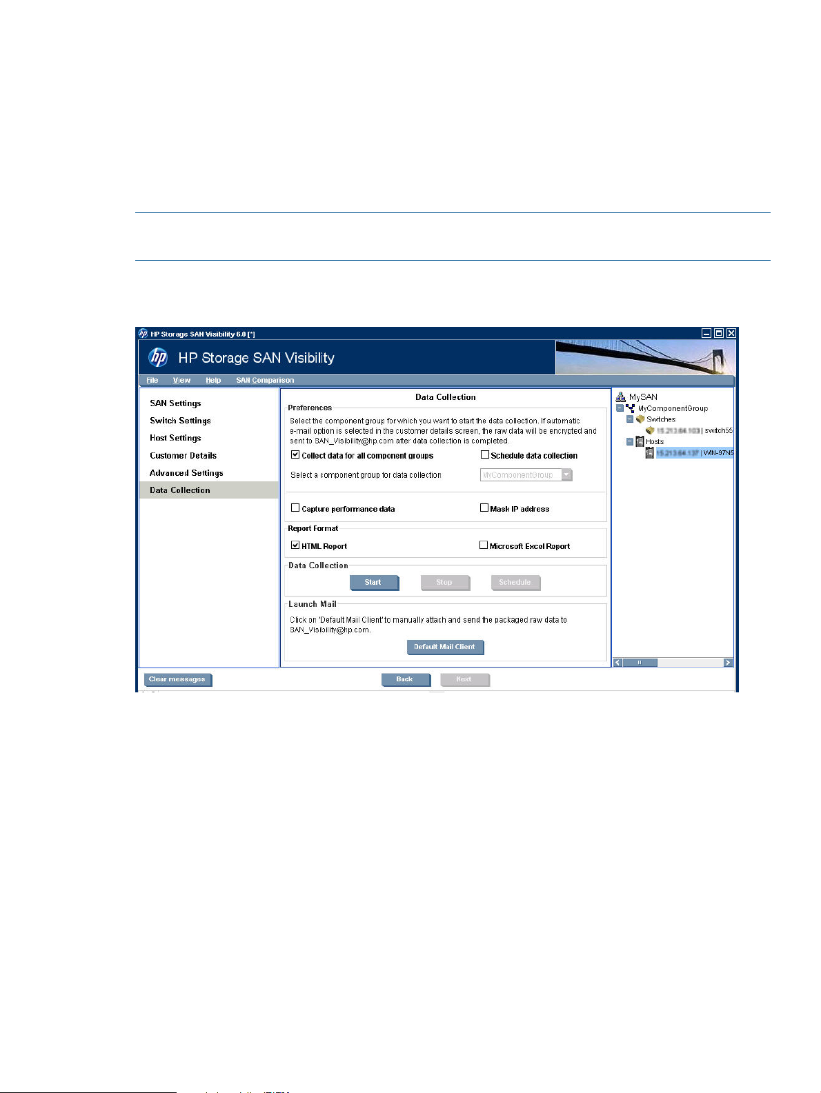
To initiate data collection, complete the following steps:
Figure 23 Data Collection Window
1. Click Data Collection from the navigation area of the SAN Visibility GUI. The Data Collection
window opens, as shown in Figure 23
2. Select a component group from the Select a component group for data collection dropdown
list, or select Collect data for all component groups check box if you want to initiate data
collection for all the component groups.
3. Select Schedule data collection check box if you want to schedule data collection. When you
select this option, the Schedule button is enabled. To schedule data collection, do the following:
Using SAN Visibility 35
Page 36

a. Click Schedule.
The Schedule Data Collection window is displayed.
Figure 24 Schedule Data Collection
b. Select the Start time.
By default, the start time is displayed as 12:00 AM.
c. Select an option to schedule data collection. You can schedule data on a daily, weekly,
or monthly basis.
d. Select the start date and end date to schedule data collection.
By default, the current date is displayed as the start date and end date.
e. Click Schedule to schedule data collection.
f. Click Cancel to cancel the scheduled data collection.
g. Click Exit to exit from the Schedule Data Collection window.
After the scheduled data collection is complete, you will receive a raw data file (.hp
extension) of the scheduled data collected report by email to the mail id specified in
the Customer Details window.
h. Email the raw data file to SAN_Visibility@hp.com with the following subject line:
HP Storage SAN Visibility Report Request
4. Select Capture Performance data check box if you want to capture the performance data for
all the component groups in the SAN.
NOTE: Selecting Capture Performance data may increase the total time for the data collection.
The performance charts are available in the SAN Visibility report only if this option is chosen.
5. Select Mask IP Address check box if you do not want to send the IP address information (in
the raw report) outside your network.
36 Using SAN Visibility
Page 37

6. Select a format for the report by selecting HTML Report or Microsoft Excel Report check box.
You also have an option to receive the report in both the formats. The processed reports are
sent in separate emails.
NOTE: The size of the processed report may be large depending on your SAN configuration.
7. Click Start Data Collection to initiate data collection for a specific component group, or for all
the component groups depending on the requirement. A message is displayed in the message
area on successful completion of data collection. The Raw Data window is displayed as shown
in Figure 28 (page 42).
Click Stop Data Collection if you want to stop the data collection process. The following
message is displayed in the message area: "Data Collection stopped successfully".
8. Review the content of the raw data and click Close to send the raw data to HP for processing.
9. Click Default Mail Client to launch your default email client.
NOTE: This button is enabled only if you have chosen not to automatically send the collected
raw data to HP for processing. For more information on how to automatically send raw data
collection to HP for processing, see “Enabling auto emailing of raw data” (page 39).
10. Attach the <SAN_Name>.hp file located at: <Install_Dir>\reports\ to your email,
where <SAN_Name> is the name of your SAN.
11. Email this raw data file to: “SAN_Visibility@hp.com” with the following subject line: “HP
Storage SAN Visibility Report Request”.
An automated email response is mailed back to you confirming the receipt of the raw data file.
On completion of the SAN analysis, you will receive a detailed SAN Visibility report containing
the SAN topology map, device inventory, high level SAN summary, and recommendations. It
normally takes up to 1 business day to send back the processed report.
NOTE: Do not use “HP SAN Visibility query” as your email subject for SAN Visibility report
requests.
Data collection methods
The SAN Visibility uses the following two methods for data collection:
• “SNMP based data collection” (page 37)
• “SMI-Agent based data collection (for Brocade switch)” (page 37)
SNMP based data collection
The SNMP based data collection is the default data collection method used by SAN Visibility.
SMI-Agent based data collection (for Brocade switch)
If you want to use the SMI-Agent based data collection method, then provide the CIMOM server
details as discussed below. The SAN Visibility allows only local user accounts to retrieve data from
the Brocade SMI-Agent (if the user authentication option is enabled at the Brocade SMI-Agent).
If the SMI-Agent based data collection fails to run, then the SAN Visibility uses the SNMP based
data collection method.
NOTE: Ensure that SMI-Agent (120.6.0 a) is installed and running in the machine. To start the
CIMOM server, select Start > Program > SMIAgent120.6.0a > Start CIMOM.
To enter CIMOM server setting details:
1. Select View > CIMOM Server Settings... The CIMOM server settings window is displayed, as
shown in Figure 25 (page 38).
Using SAN Visibility 37
Page 38

2. Enter the CIMOM server IP address in the CIMOM Server IP Address box.
3. Enter the user name in the User Name box.
4. Enter the password in the Password box.
5. Enter the server port number in the Server Port box (default: 5988 for http and 5989 for https).
6. Click Ok.
The authorized user setting is saved, and the credentials entered is used to communicate with
the Brocade SMI-Agent during the next data collection.
NOTE: For configuring Brocade SMI-Agent user authentication, see the Brocade SMI-Agent
user guide.
Figure 25 CIMOM server setting window
Sending raw data file to HP
SAN Visibility provides an option to either automatically or manually send the raw data files to
HP for processing.
If you want to view the contents of the raw data before sending it to HP for processing, see “Viewing
raw data” (page 41).
Manually emailing raw data files to HP
To manually send the raw data file to HP for processing, complete the following steps:
1. Click Data Collection option from the navigation area of the SAN Visibility GUI to view the
Data Collection details.
2. Click Start Data Collection to initiate data collection for a specific component group, or for all
the component groups depending on the requirement.
Wait for the message to be displayed in the message area on successful completion of the
data collection. The Raw Data window is displayed as shown in Figure 28 (page 42).
3. Review the content of the raw data and click Close to send the raw data to HP for processing.
4. Click Default Mail Client. Your default email client opens.
5. Attach the <SAN_Name>.hp file located at: <Install_Dir>\reports\ to your email, where
<SAN_Name> is the name of your SAN.
38 Using SAN Visibility
Page 39

6. Email this raw data file to: “SAN_Visibility@hp.com” with the following subject line: "HP
Storage SAN Visibility Report Request".
NOTE: If the mail client is not configured on the system on which SAN Visibility is installed,
then after the data collection is complete, transfer the raw data file (.hp extension) to a system
where the mail client is configured, attach the raw data file, and send it to:
“SAN_Visibility@hp.com”.
An automated email response is mailed back to you confirming the receipt of the raw data file.
On completion of the SAN analysis, you receive a detailed SAN Visibility report containing the
SAN topology map, device inventory, high level SAN summary, and recommendations. It normally
takes up to 1 business day to send back the processed report. If the report is sent from E-mail id
other than configured mail id in HP Storage SAN Visibility GUI, then the sender will be notified
after the successful processing.
Enabling auto emailing of raw data
SAN Visibility software enables you to automatically send the data collection reports to HP for
analysis.
To enable automatic emailing of data collection reports to HP, complete the following steps:
1. Click Customer Details option from the navigation area. The Customer Details window is
displayed in the main display area.
2. Ensure that the Automatically email the collected raw data on completion check box is selected.
If the email address provided in the E-mail box is valid, then SAN Visibility automatically tries
to retrieve the SMTP server address from the email ID, and sends the raw data file to HP for
processing.
NOTE: Ensure that the email address provided in the Customer Details window is accurate.
The processed reports are sent to this email address.
3. Select the SMTP server address from the SMTP Server drop down box to send the raw data
files to HP for processing, as shown in Figure 26 (page 40). Step 2 is executed if the SMTP
server address is not specified explicitly.
For more information on how to find the SMTP server IP address, see Determining the SMTP
server IP address.
NOTE: If the Automatically e-mail the collected raw data on completion check box is not
selected, then the SAN Visibility software automatically activates the Launch Default Mail Client
button available in the Data Collection window. Click the Launch Default Mail Client button
after the data collection is complete to launch the default mail client, attach the packaged raw
data file (.hp format), and send it to: “SAN_Visibility@hp.com” for processing.
Using SAN Visibility 39
Page 40

Figure 26 SMTP Server details
EVA to 3PAR Storage Migration
SAN Visibility provides a 3PAR StoreServ Storage migration option. Hence, this feature can be
used as a pre-check for array migration.
In HP Storage SAN Visibility you can select an EVA model (From Array Model) and a 3PAR
StoreServ Storage model (To Array Model) for the migration recommendation. Field/support
engineers use the SAN Visibility Migration feature before migrating from EVA arrays to 3PAR
StoreServ Storage array in a customer’s SAN. This feature generates a report of all the incompatible
components (Switch/Host) for 3PAR StoreServ Storage array to be migrated. Also, it generates
the firmware/driver recommendation for SAN components if the components are running with an
incompatible version.
The following 3PAR StoreServ Storage array models are supported for recommendation:
• HP 3PAR StoreServ 10400 Storage
• HP 3PAR StoreServ 10800 Storage
• HP 3PAR StoreServ 7200 Storage
• HP 3PAR StoreServ 7400 Storage
• HP 3PAR T400 Storage
• HP 3PAR T800 Storage
• HP 3PAR F200 Storage
• HP 3PAR F400 Storage
The 3PAR StoreServ Storage migration window displays the following details as shown in Figure 27
(page 41):
• Array Name
• Array Model
• Node WWN
• Target 3PAR StoreServ Storage Array
40 Using SAN Visibility
Page 41
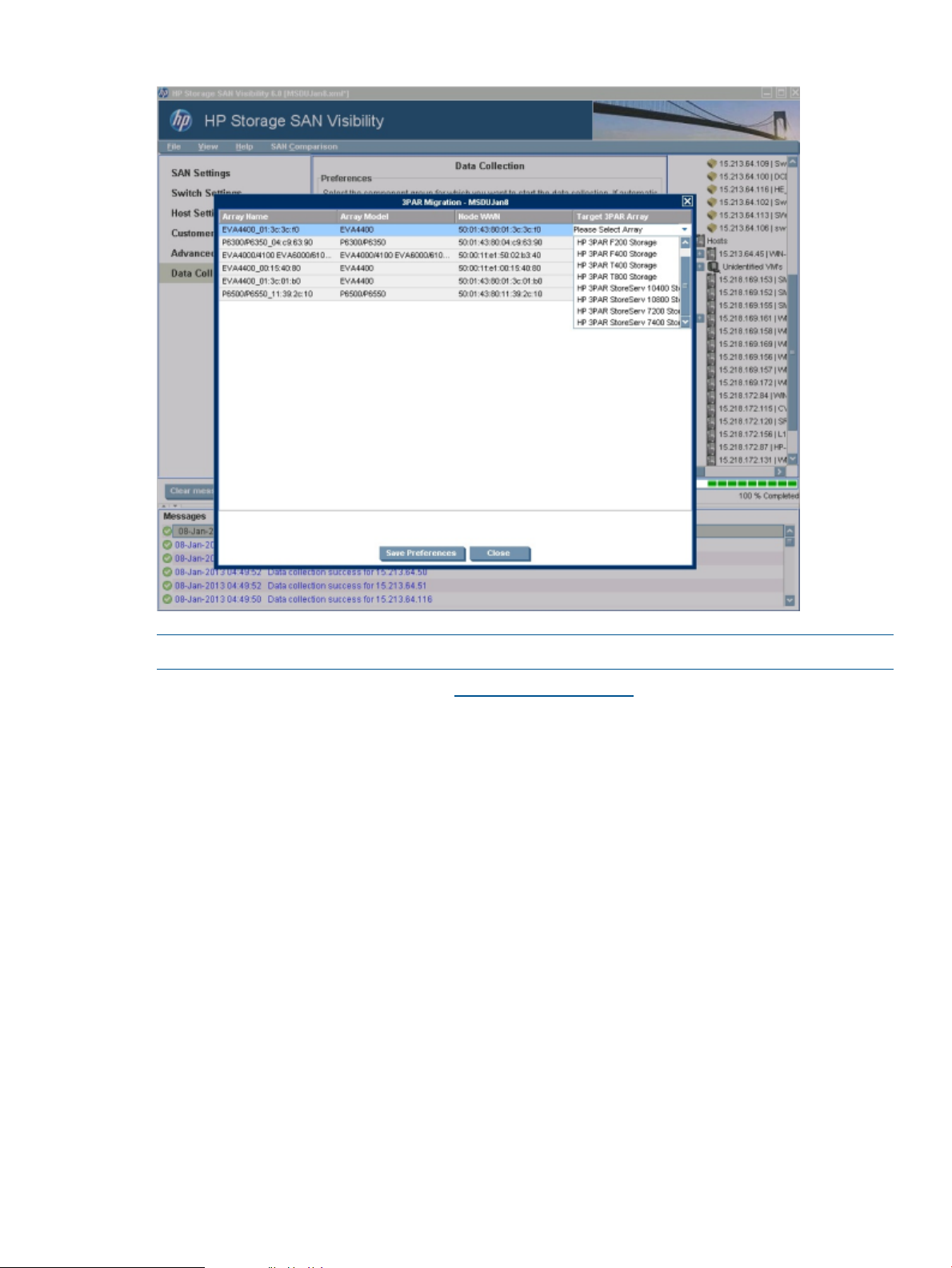
Figure 27 EVA to 3PAR StoreServ Storage Migration screen
NOTE: Click Close to skip the migration process.
The SAN Visibility raw report is sent to SAN_Visibility@hp.com, which contains the user selected
migration recommendation request. If there are any compatible switches and hosts, then the
outdated firmware/driver is reported. The report with recommendation for migration is sent back
to the configured email address.
Viewing raw data
SAN Visibility provides an option to view the contents of the raw data before sending it to HP for
processing.
To view the raw data before sending it to HP for processing, select View > Raw Data — <SAN
Name>. The Raw Data window is displayed, as shown in Figure 28 (page 42).
Using SAN Visibility 41
Page 42

Figure 28 Raw Data window
Determining the SMTP server IP address
To find the SMTP server IP address, complete the following steps:
1. Select Start > Run, and enter cmd in the box.
2. Click OK to open the MS-DOS command prompt.
3. Enter the nslookup <primary_domain_name> command, where
<primary_domain_name> is your domain name, and press Enter.
The primary DNS server address is displayed.
4. Enter the nslookup command, and press Enter to go to the shell prompt.
5. Enter the server <DNS_server_name> command, and press Enter.
6. Enter the <primary_domain_name>, where <primary_domain_name> is your domain
name, and press Enter.
7. Enter the set query=mx command, and press Enter.
8. Enter the <primary_domain_name>, and press Enter.
The detected SMTP server IP addresses are displayed, as shown in Figure 29 (page 42).
9. Select an appropriate SMTP server from the list.
10. Enter exit, and press Enter to exit from the shell prompt.
11. Enter exit, and press Enter to exit from the MS-DOS command prompt.
Figure 29 Determining SMTP server details
42 Using SAN Visibility
Page 43

Viewing reports
The SAN Visibility software enables you to automatically email the collected raw file to HP for
processing. The processed report, as shown in Figure 30 (page 45), is mailed back to the email
address specified in the Customer Details screen. Internet Explorer 8 or Internet Explorer 9 is
required to view the HTML report. You have an option to receive the processed report in HTML or
Microsoft Excel format. It normally takes up to 1 business day to send back the processed report
to the customer.
To open and view the processed report, complete the following steps:
1. Save the attached file (.hppr file) at a preferred location (do not change the file extension),
NOTE: The compressed and encrypted processed report (.hppr file), which is mailed back
to the email address specified in the Customer Details window, must be opened on the system
where HP Storage SAN Visibility is installed.
2. Double-click the saved file to extract the processed report. The processed report is extracted
and are stored at: <Install_Dir>\ExtractedProcessedReports\<SAN Name>\
3. Navigate to the above location.
4. Open one of the following files:
• Index.html — if you have selected to receive the processed report in HTML format in
the Data Collection window. You can use any web browser to view the HTML report.
NOTE: Some versions of the Internet Explorer does not allow ActiveX contents, and a
message is displayed on these browsers informing that the ActiveX contents have been
blocked. In order to view the complete SAN Visibility report with the topology diagrams,
select the Allow Blocked Contents option on the browser.
• <file_name>.xls — if you have selected to receive the processed report in Microsoft
Excel format in the Data Collection window.
The SAN Visibility report contains the following information:
• General information:
Customer Contact Details – Customer information entered in the Customer Details window,
◦
an overview of the contents, and the layout of the report package.
◦ License Information – SAN Visibility License agreement
• SAN Information:
◦ High Level Fabric Summary – Contains a summary of all the fabrics in the SAN, including
component information, such as switches, arrays, hosts, and HBAs.
• Fabric Information (for each fabric in the SAN):
Displays switches, arrays, HBAs, and their connectivity in HTML format.HTML Topology Diagram
Displays switches, arrays, HBAs, and their connectivity in Microsoft Visio.Visio Topology
Switch Details
Displays the list of switches. Select a switch from the list to view the detailed
switch report.
Displays SAN device nodes and connections found in the fabric.Node List
Storage Devices
HBA Details
Displays the list of storage arrays and tape devices present in the SAN. Select
an array from the list to view the detailed array report. Select a tape device
from the list to view the detailed tape device report.
Displays the list of HBAs. Select an HBA from the list to view the detailed HBA
report.
Using SAN Visibility 43
Page 44

Hosts
Displays the list of hosts. Select an host from the list to view the detailed host
report.
Performance Charts
Zone Report
VSAN Details
Recommendations
FICON Report
NPIV Details (Switch)
NPIV Details (HBA)
Provides I/O performance statistics on a per port basis for each switch.
Performance charts are generated only when you have selected the Capture
Performance Data check box in the Data Collector screen.
Summarizes the zones identified and displayed in the fabric layout. If there
are multiple zones in a fabric, each zone and its member devices are displayed
in a separate table.
For a Cisco switch, this report summarizes the VSANs identified and displayed
in the fabric layout. If there are multiple VSANs in a fabric, each VSAN and
its member devices are displayed in a separate table.
Provides best practice recommendations for each fabric, such as recommended
firmware versions on the switches, hanging zone, domain 1 warning, domain
8 warning, duplicate domain warnings, and information on the firmware and
the driver compatibility of the HBAs and the switches that are directly or
indirectly connected with the HP Storage EVA 4000/6000/8000 class of disk
arrays, with V6 firmware.
Provides details of the FICON Channel Path's in the SAN, including the Channel
Path ID, LPAR, WWN, Firmware and Port details for each channel path.
Provides details of all the SAN components seen by an NPIV enabled ports.
The report contains the port numbers on which the NPIV device is connected,
the real and virtual WWPNs as seen by each port, and the zone names that
are part of the NPIV enabled ports and WWPNs.
Provides the details of all the NPIV configured ports of the HBA. It contains
virtual HBAs (VHBAs) and WWPNs of the associated physical HBAs.
Compatibility
Zone non-adherence
Migration Recommendation
HP-UX Fibre Channel (td) Host
Bus Adapter Support Matrix
Summarizes the compatibility between various components in the SAN. The
Compatibility Analysis is done between the Host and Switch, Switch and
Storage systems, Host and Storage systems using HP SDG guidelines.
Summarizes the outcome of analysis done on Fabric and Zone. Fabric Analysis
consists of running SAN Design Guide (SDG) rules on the SAN to check for
any potential non-adherence. The Fabric Analysis is done for HP or HP OEM
hardware only.
Summarizes the migration recommendation from EVA storage array to 3PAR
StoreServ storage array that are selected in the "Migration" wizard of SAN
Visibility tool during data collection. The analysis is done using the following
criteria:
◦ Compatibility between migrated Storage and existing switches in the fabric.
◦ Compatibility between migrated Storage and existing Host OSs in the fabric.
◦ Existing Switch and HBA component firmware.
◦ Driver recommendation with respect to migrated Storage.
Verifies that your HBA's driver is included with your Operating Environment
or to check which driver you need when adding a network or I/O HBAs.
44 Using SAN Visibility
Page 45

Figure 30 Processed report
Comparing SAN
SAN Visibility provides an option to compare SANs and generate reports.
To use this feature, you must have the SVReport.comp file. The SVReport.comp file is bundled
with the processed report.
To compare SANs, complete the following steps:
1. Select SAN Comparison > Compare SAN.
The SAN Comparison window is displayed.
2. Select File > Open > Dataset1.
By default, it opens the ExtractedProcessedReports folder.
3. Select the SVReport.comp file for comparison.
4. Follow steps 1–3 to load Dataset 2.
If you select any node in Dataset1 or Dataset 2, the corresponding details of the node will be
displayed.
5. Select Highlight Changes > Dataset1 or Dataset2 to check the changes.
The changes will be highlighted in red (see Figure 31 (page 46)), and the new devices are
shown in blue.
Using SAN Visibility 45
Page 46

Figure 31 SAN comparison details
6. Select Filter and choose the components for comparison. Select Highlight Changes > Dataset1
or Dataset2 to view the changes.
You can filter SAN based on the following components:
• Arrays
• HBAs
• Hosts
• Switches
• Zones
7. Select Generate Report > Compare Dataset1 with Dataset2 or Compare Dataset2 with Dataset1
to generate the compared report.
A compared report is generated.
By default, it opens the My Documents folder. Save the compared report by selecting the
folder of your choice.
8. Decrypt the report to view the compared report details.
9. Select Remove > Dataset1 or Dataset2, to remove datasets, or select Remove > Remove All
to remove both the datasets.
10. Select Exit to exit from the SAN comparison window.
Saving the current configuration file
SAN Visibility enables you to save the SAN configuration data for future use.
To save the SAN configuration file, complete the following steps:
1. Select File > Save to save the SAN configuration.
2. Enter a file name in the File Name box.
3. Click Save to save the configuration for future reference.
By default, the SAN configuration file is saved at the following location:
<Install_Dir>\profiles.
NOTE: A [*] is displayed in the SAN Visibility GUI title bar if you did not save the SAN
configuration data. Once the configuration file is saved, the name of the file is displayed in the
SAN Visibility GUI title bar.
46 Using SAN Visibility
Page 47

Opening an existing configuration file
SAN Visibility enables you to open an existing configuration file [.xml extension] that is created
and saved earlier by SAN Visibility.
To open an existing configuration file, complete the following steps:
1. Select File > Open.
2. Locate and select the previously saved configuration file you want to open.
NOTE: Previously saved configuration files from SAN Visibility can be opened from SAN
Visibility. All profiles are saved in”< INSTALL_DIR >\Hewlett-Packard\HP
SANVisibility\profiles"
3. Click Open.
The existing configuration is opened. The customer and configuration details (including SAN,
component group, and switch details) are populated and shown in the SAN Visibility GUI
window.
Exiting from SAN Visibility
To exit from SAN Visibility software, select File > Exit.
Using SAN Visibility 47
Page 48

4 Support and other resources
Contacting HP
For worldwide technical support information, see the HP support website:
http://www.hp.com/support
Before contacting HP, collect the following information:
• Product model names and numbers
• Technical support registration number (if applicable)
• Product serial numbers
• Error messages
• Operating system type and revision level
• Detailed questions
Subscription service
HP recommends that you register your product at the Subscriber's Choice for Business website:
http://www.hp.com/go/e-updates
After registering, you will receive e-mail notification of product enhancements, new driver versions,
firmware updates, and other product resources.
Related information
Documents
The following documents provide related information:
• HP Storage SAN Visibility 6.0 Release Notes
• HP Storage SAN Visibility 6.0 Quick Start Guide
To access the online help, click Help and select SAN Visibility Help within the HP Storage SAN
Visibility graphical user interface (GUI).
You can find these documents from the Manuals page of the HP Business Support Center website:
http://www.hp.com/support/manuals
Websites
For additional information, see the following HP websites:
• http://www.hp.com
• http://www.hp.com/go/storage
• http://www.hp.com/support/manuals
• http://www.hp.com/sbso/serverstorage/index.html
• http://h18006.www1.hp.com/storage/networking/sansolutions.html
• http://h18006.www1.hp.com/products/storageworks/san/index.html
Documentation feedback
HP welcomes your feedback.
48 Support and other resources
Page 49

To make comments and suggestions about product documentation, please send a message to:
“docsfeedback@hp.com”. All submissions become the property of HP.
Product feedback
To make comments and suggestions about HP Storage SAN Visibility, please send a message to:
“SAN_Visibility@hp.com”, with the subject as “HP SAN Visibility query”.
Typographic conventions
Table 5 Document conventions
ElementConvention
Cross-reference links and e-mail addressesBlue text: Table 5 (page 49)
Website addressesBlue, underlined text: http://www.hp.com
Bold text
Monospace text
Monospace, italic text
• Keys that are pressed
• Text typed into a GUI element, such as a box
• GUI elements that are clicked or selected, such as menu
and list items, buttons, tabs, and check boxes
Text emphasisItalic text
• File and directory names
• System output
• Code
• Commands, their arguments, and argument values
• Code variables
• Command variables
Emphasized monospace textMonospace, bold text
WARNING! Indicates that failure to follow directions could result in bodily harm or death.
CAUTION: Indicates that failure to follow directions could result in damage to equipment or data.
IMPORTANT: Provides clarifying information or specific instructions.
NOTE: Provides additional information.
TIP: Provides helpful hints and shortcuts.
Product feedback 49
Page 50

A DCOM configuration
To configure DCOM:
1. Click Start > Programs > Administrative Tools > Component Services.
2. Expand the Component Services node followed by the Computers node.
3. Right-click My Computer and select Properties.
4. Click Default Properties and do the following:
• Select Enable Distributed COM on this computer
• Set the Default Authentication Level to Connect (None also works)
• Set the Default Impersonation Level to Identify (Impersonate also works)
5. Click Default COM Security.
6. Under Default Access Permissions , click Edit Default and select Add SYSTEM, INTERACTIVE,
and NETWORK.
The user whose authentication credentials will be used to access the COM application must
also be included in this list. You can add the specific user or add a group that the user belongs
to. Possible values include:
• Domain\Username (a specific user)
• Domain\Administrators (all administrators on a specific domain)
• Everyone (all users)
7. Under Default Launch Permissions, click Edit Default.
NOTE: Ensure that the Default Launch Permissions have the same values as the Default Access
Permissions.
8. Click Default Protocols.
NOTE: Ensure that the Connection-oriented TCP/IP is listed first.
9. Expand the Component Services node followed by the Computers and My Computer nodes,
click DCOM Configuration. Right-click on the Windows Management and Instrumentation
properties.
10. Click General and set the Authentication Level to Default.
11. Click Location and select Run application on this computer.
12. Click Security and do the following:
• Set Launch Permissions to Use Default
• Set Access Permissions to Use Default
• Set Configuration Permissions to Use Default
13. Click Identity and select the launching user.
This setting specifies the account that will be used to run the COM application after it is
launched by a client program. The launching user is the user account of the client process that
launched the server, and is the recommended setting. Depending on the COM application
you want to connect to, you may have to change the setting to one of the following:
• The interactive user - The user that is currently logged on to the machine hosting the COM
application.
• This user - Specify a user account that will always be used to run the COM application
regardless of which user is accessing it.
14. Click Endpoints, and select default system protocols.
If you still get an "access denied" or a "permission denied" error after configuring your DCOM
settings, try rebooting your machine to allow the new settings to take effect.
50 DCOM configuration
Page 51

To verify that the Local System account is configured for the IIS Admin service:
a. Click the Start > Settings > Control Panel > Tools > Services.
b. Double-click WMI Service.
c. On the Log On tab, ensure that the option for Local System Account is selected.
d. Under Services, check the services listed to verify that each has the Log On option set to
the Local System account.
NOTE:
• If host discovery and data collection fails, then ensure that the LAN Manager Authentication
Level is set to Send LM & NTLM responses by doing the following:
1. Click Start, click Settings, click Control Panel, click Administrative Tools, click Local Security
Policy.
2. In the Local Security Settings dialog box, click Local Policies, and then click Security
Options.
3. Double-click Network Security: LAN Manager Authentication Level.
4. Select Send LM & NTLM responses.
5. Click OK and exit out of Local Security Settings.
• If host discovery and data collection still fails then do the DCOM configuration as follows.
DCOM configuration impacts internal OS settings.
51
Page 52

B Troubleshooting
This chapter discusses some common issues that you may encounter while using SAN Visibility
software, including:
• “Network connectivity issues” (page 52)
• “SNMP access failures” (page 52)
• “SMI-S Access failures” (page 53)
• “Changing SNMP proxy settings for HP Storage 8/20q and QLogic FC switches” (page 53)
Network connectivity issues
Data collection can fail because of any of the following network issues:
• No power.
• The LAN cable is unplugged.
• The device is not configured properly.
• The IP address is incorrect.
• Ports are in exclusive use, but the device is working.
• Ports are temporarily blocked on the Brocade switches by an administrator.
SNMP access failures
McData and Cisco Fibre Channel switches
The SNMP Read community must be set to collect data for McData and Cisco Fibre Channel
switches.
To set up the SNMP Read Community, complete the following steps:
1. Open a telnet session for the switch.
2. Enter the show snmp command. If the Read community is not set up, a blank screen appears
under the community and the group access columns.
3. To set up the community string, enter the snmp-server community public command (a
well known community public is set in this example).
4. Enter the show snmp command again. The community and group access columns are
configured.
5. Close the telnet session.
Brocade Fibre Channel switches
The SNMP Read community must be set to collect data for Brocade Fibre Channel switches.
NOTE: Configure the SNMP access list to its default value (0.0.0.0) or with the IP address of
the host on which HP SAN Visibility is installed.
To set up the SNMP Read Community, complete the following steps:
1. Open a telnet session for the switch.
2. Enter the agtcfgset command.
3. Configure the Read only community string (Community (ro): ) for SNMP community and
trap recipient configuration. The default value of the community string is public.
4. Enter the default IP address (0.0.0.0) or the IP address of the host where HP SAN Visibility
is installed for SNMP access list configuration.
5. Close the telnet session.
52 Troubleshooting
Page 53

SMI-S Access failures
While collecting data through SMI-S for Brocade switches, if there are any connection failures to
the switches or if the SMI agent is stopped, then the data collection falls back to SNMP, and a
report is generated.
For more information, contact HP or visit Servers & Storage expertise center at: http://www.hp.com/
sbso/serverstorage/index.html
Changing SNMP proxy settings for HP Storage 8/20q and QLogic FC switches
To change the SNMP proxy setting parameter for HP Storage 8/20q and QLogic FC switches,
complete the following steps:
1. Login to the switch you want to change the SNMP proxy settings.
2. Run the admin start command to start the session in admin mode.
3. Run the following command: set setup snmp.
4. Set the SNMP proxy parameter (ProxyEnabled) to "False”.
5. Save and exit from the session.
SMI-S Access failures 53
Page 54

C Error codes
This chapter discusses the error codes that may be displayed while using SAN Visibility software.
Troubleshooting the error codes
Table 6 (page 54) discusses the error codes and troubleshooting information.
Table 6 Error codes and troubleshooting
TroubleshootingPossible CauseDescriptionError Code
101
104
105
Data collector service
(HPSanVisibilityDataCollector)
is not running
Missing data102
IP address is invalid103
Some of the Brocade switches
for which you want to collect
data have blank login or
password select the individual switch and
Server: <server-name> is not
responding to the SMTP
request, this may not be a valid
SMTP server
SAN Visibility data collector component runs
as Windows service. Error occurs if the
service is not running.
This error occurs if the mandatory data fields
are empty.
are not valid.
Login and password information is required
for Brocade switches for data collection, or
error occurs if any of these fields are blank.
This error occurs if you are testing an SMTP
server, which is not a valid SMTP server. Test
process does not differentiate between a valid
non-SMTP server and a non-existent server.
From your Desktop, select Start
> Control Panel > Administrative
Tools > Services, and look for
HPSanVisibilityDataCollector
service. Right click, and start the
service.
Enter the valid data in the
mandatory fields. For example:
Read Community is required
while discovering an FC switch.
If read community is not given
and you try to discover the
switch, you receive the message:
“Read Community is required”
Enter a valid IP address.IP addresses starting and ending with zero
Enter the valid login and
password before performing
subnet search. Or, you canwhen discovering connected switches. This
update the login and password
from the Switch Settings tab.
Provide valid SMTP server name
or IP address.
54 Error codes
Invalid Configuration file106
Special character validation107
Invalid login or password201
This error occurs if you are trying to open a
configuration file which is not created by the
SAN Visibility software.
The acceptable characters for the Customer
Details filed are: a-z A-Z _ - , . # ( ) and space
character, and the maximum number of
characters allowed in any editable field is
255. This error occurs if you enter anything
other than the accepted characters for the
Customer Details fields or you exceed the
maximum allowed characters in any editable
filed.
This error occurs when login or password
supplied for the Brocade switches is incorrect.
Login and password are validated at two
places: one while discovering the connected
switches and second while collecting data.
Provide a valid configuration
file.
Enter valid characters in the
Customer Details fields.
Provide valid login or password
for Brocade switches.
Page 55

Table 6 Error codes and troubleshooting (continued)
TroubleshootingPossible CauseDescriptionError Code
203
Data Collection failed202
<IP-Address> is not responding
to SNMP query
This error occurs when data collection for a
particular switch or all switches fails. There
can be one or more reasons for this, such as:
• Any unsupported firmware or unsupported
switch OS
• This error occurs if the switch does not
respond to some OIDs while collecting the
switch data. A switch does not respond if
the SNMP data type does not match with
the standard data types for the switch's
SNMP agent.
• Any unexpected SNMP error while
collecting data for that particular switch.
This error occurs when a particular IP address
does not respond to the SNMP query. There
can be one or more reasons for this, such as:
• Device with this IP address does not exist
or is switched off.
• Device with this IP address exists and is
switched on, but is not an FC switch.
• Device with this IP address exists, is
switched on, and is a valid FC switch.
However, a restricted SNMP access list is
configured in this switch.
• Incorrect Read Community string.
Send the detailed information
about the switch and its firmware
to:
“SAN_Visibility@hp.com”
Ensure that the device with this
IP address exists and is switched
on. If a restricted SNMP access
list is configured in the switch,
add the IP address of the system
running SAN Visibility in the
access list, and try again. Verify
that the SNMP Read Community
is same as what is configured in
the switch.
204
301:XXX
303
Fatal error - Data Collection
abort failed
Error in packaging raw report.
Where XXX is the code
returned by the system.
Error in emailing the packaged
report
This error occurs when an unexpected
response from data collector is received while
aborting the data collection.
There can be various reasons for this error,
such as changes in the Windows patch level,
unsupported patch, and so on.
This error occurs when SAN Visibility software
fails to send the packaged report to HP. There
can be one or more reasons for this, such as:
• SMTP server address mentioned in the
Data Collection tab is not a valid SMTP
server.
• Security policy settings on the SMTP server
allow only authenticated users to submit
mail for subsequent delivery. The SMTP
server does not accept email submissions
from anonymous users.
• An Exchange server name is specified as
the SMTP server.
• Client does not have permissions to send
on behalf of ‘From' address. The session
does not have the
ms-Exch-SMTP-Accept-Any-Sender
permission.
This is a fatal error. Restart
HPSanVisibilityDataCollector
service. From your Desktop,
select Start > Control Panel >
Administrative Tools > Services,
and look for
HPSanVisibilityDataCollector
service. Right-click, and restart
the service.
Send the complete error code
with your system information to:
“SAN_Visibility@hp.com”
Contact your system
administrator or Exchange
administrator for more
information.
Troubleshooting the error codes 55
Page 56

Table 6 Error codes and troubleshooting (continued)
TroubleshootingPossible CauseDescriptionError Code
303:002
303:004
303:005
303:007
303:008
303:009
Input Error303:001
Fatal Error - MFC initialization
failed
Not enough memory303:003
Unable to create socket for the
SMTP server
Unable to connect to the SMTP
server
SMTP server not ready for data303:006
SMTP server did not terminate
the session
Not connected to the SMTP
server
No recipients for the SMTP
server
This error occurs when the SMTP server
address provided is invalid.
are missing.
SAN Visibility is running is out of memory.
This error occurs when no more socket
connections are allowed on the host system.
This error occurs when the SMTP server is not
responding or when there is no network
connection.
This error occurs when the server is busy, and
does not respond.
This error occurs when the server is busy, and
does not respond.
This error occurs when the server is busy or
the number of connections have exceeded the
connection limit.
This error occurs when the SMTP server
address provided is not valid.
Provide a valid SMTP server
address.
Reinstall the software.This error occurs when the required dll files
Retry after some time.This error occurs when the system on which
Check the number of
connections existing on the host
system.
Verify if the SMTP server is
accessible from the network.
Retry after some time or send the
raw report to:
“SAN_Visibility@hp.com”
Retry after some time or send the
raw report to:
“SAN_Visibility@hp.com”
Retry after some time or send the
raw report to:
“SAN_Visibility@hp.com”
Provide a valid SMTP server
address.
303:010
402
Incorrect or wrong email
address
Unknown error occurred303:011
Error in discovering host401
Error in discovering host Interface not defined
Host is not responding403
Host is not responding404
The OS is unsupported405
address is provided in the Customer Details
window.
This error occurs when an inappropriate
operation is performed by the SAN Visibility
software.
during host discovery is incorrect.
is missing from the resources directory of the
installed folder.
if the credentials provided are incorrect.
This error occurs if the user does not have the
required privileges.
This error occurs if the server operating system
is not supported.
Provide a valid email address.This error occurs when an invalid email
Write a mail to:
“SAN_Visibility@hp.com” with
the following subject line: “HP
SAN Visibility Query” with a
detailed description of the
occurrence of the error.
Enter the correct login name.This error occurs if the login name provided
Reinstall the software.This error occurs if the validation.xml file
Verify the credentials provided.This error occurs if the host does not exist or
Provide the user with super user
privileges.
Verify if the operating system is
supported. For more information,
see “Supported operating
systems” (page 22).
56 Error codes
Page 57

Table 6 Error codes and troubleshooting (continued)
TroubleshootingPossible CauseDescriptionError Code
406
407
Failed data collection for the
host
The connection to the Host IP
failed
This error occurs when the supported
interfaces fails to collect data for a specified
host.
This error occurs when sufficient OS
information is not available to collect data.
Ensure that the necessary
configurations are performed on
the specified server.
For more information, see
“Server configurations” (page
22).
Verify if the operating system is
supported. For more information,
see “Supported operating
systems” (page 22).
Troubleshooting the error codes 57
Page 58

Glossary
This glossary defines terms used in this guide or related to this product and is not a
comprehensive glossary of computer terms.
A
CIMOM Common Information Model Object Manager.
F
Fabric A contiguous switched network composed of high-speed fiber connections. Each fabric is a single
instantiation of the fabric services. A fabric is an active and intelligent non-shared interconnect
scheme for nodes.
G
GUI Graphic User Interface.
H
HBA A Host Bus Adapter is an I/O device that serves as the interface connecting a host system to the
SAN (Storage Area Network).
I
IPv6 IPv6 or Internet Protocol version 6 is the next generation protocol for the Internet. One of the main
benefits of IPv6 over IPv4 is the large address-space that contains (addressing) information to
route packets for the next generation Internet.
I
IPv4 Internet Protocol version 4 (IPv4) is the fourth revision in the development of the Internet Protocol
(IP) and the first version of the protocol to be widely deployed. IPv4 is a connectionless protocol
for use on packet-switched Link Layer networks (e.g., Ethernet).
N
NPIV N_Port ID Virtualization or NPIV is a Fibre Channel facility allowing multiple N_Port IDs to share
a single physical N_Port. This allows multiple Fibre Channel initiators to occupy a single physical
port, easing hardware requirements in Storage area network design, especially where virtual
SANs are called for.
S
SAN Storage Area Network with one or more fabrics. A configuration of networked devices for storage.
SDG SAN Design Guide.
SMI-S Storage Management Initiative - Specification.
SMTP Simple Mail Transfer Protocol. A protocol used in TCP/IP networks for sending and receiving
email.
Storage array A storage system consisting of one or more storage controllers and the disk drives they manage.
SV SAN Visibility
T
Topology An interconnection scheme that allows multiple servers and storage devices to communicate.
Arbitrated loop and switched fabric are examples of Fibre Channel topologies.
58 Glossary
Page 59

W
WINRM Windows Remote Management.
WWN World Wide Name. A unique Fibre Channel identifier consisting of a 16-character hexadecimal
number. A WWN is required for each Fibre Channel communication port.
59
 Loading...