

Page 1

hewlett-packard company
virtual private networking
concepts guide
Hewlett-Packard Company
HP: 5971-3009
P/N: A5 5310-00 1
March 2001
Page 2

ii
Page 3

Disclaimer
Disclaimer
DisclaimerDisclaimer
Information in this document is provided in connection with
Hewlett-Packard Company products. No license, express or
implied, by estoppel or otherwise, to any intellectual property
rights is granted by this d ocument. Except as provided in
Hewlett-Packard Company’s Terms and Conditi on s of Sale for
such products, Hewlett-Packard Company assumes no liability
whatsoever, and Hewlett-Packard Company disclaims any
express or implied warranty, relating to sale and/or use of
Hewlett-Packard Company products including liability or
warranties relating to fitness for a particular purpose,
merchantability, or infringement of any patent, copyright or
other intellectual property right. Hewlett-Packard Company
products are not intended for use in medical, life saving, or life
sustaining applications.
Hewlett-Packard Company may make changes to specifications
and product descriptions at any time, without notice.
Hewlett-Packard Company Virtual Private Networking
This
Concepts Guide
furnishe d under lic e ns e and ma y only be u s ed or copied i n
accordance with the terms of the license. The in formation in this
manual is furnished for inf ormation al use onl y, is subject t o
change without notice, and should not be construed as a
commitment by Hewlett -Packard Company. Hewlett-Packard
Company assumes no respon sibility or liabil ity for any errors or
inaccuracies that may appear in this document or any software
that may be provided in association with this document.
, as well as the software described in it is
Except as permitted by such license, no part of this document
may be reproduced, stored in a retrieval system, or transmitted
in any form or by any means without the express written consent
of Hewlett-Packard Company.
Copyright © Hewlett-Packard Company 2001.
iii
Page 4

iv
Page 5

Contents
Contents
ContentsContents
HP VPN Concepts Guide Overview
HP VPN Concepts Guide Overview
HP VPN Concepts Guide OverviewHP VPN Concepts Guide Overview
HP VPN Concepts Guide Overview . . . . . . . . . . . . . . . . . . . . . . . . . . . . . . . . . . . . . . . . . 1-1
HP VPN Suite Overview . . . . . . . . . . . . . . . . . . . . . . . . . . . . . . . . . . . . . . . . . . . . . . . . . . . 1-2
Operational Overview. . . . . . . . . . . . . . . . . . . . . . . . . . . . . . . . . . . . . . . . . . . . . . . . . . . . . 1-5
TCP/IP Basics Overview. . . . . . . . . . . . . . . . . . . . . . . . . . . . . . . . . . . . . . . . . . . . . . . . . . . 1-6
Cryptographic Systems and Encryption Terminology
Cryptographic Systems and Encryption Terminology
Cryptographic Systems and Encryption TerminologyCryptographic Systems and Encryption Terminology
Cryptographic Systems and Encryption Terminology Overview . . . . . . . . . . . . . . . . . 2-1
Symmetric Cryptographic Systems. . . . . . . . . . . . . . . . . . . . . . . . . . . . . . . . . . . . . . . . . . 2-3
Data Encryption Standard (DES) . . . . . . . . . . . . . . . . . . . . . . . . . . . . . . . . . . . . . . . . . . . 2-4
Triple Pass DES. . . . . . . . . . . . . . . . . . . . . . . . . . . . . . . . . . . . . . . . . . . . . . . . . . . . . . . . . . 2-5
3DES. . . . . . . . . . . . . . . . . . . . . . . . . . . . . . . . . . . . . . . . . . . . . . . . . . . . . . . . . . . . . . . . . . . 2-7
Outer Cipher Block Chaining (CBC) . . . . . . . . . . . . . . . . . . . . . . . . . . . . . . . . . . . . . . . . 2-8
Asymmetric Cryptographic Systems . . . . . . . . . . . . . . . . . . . . . . . . . . . . . . . . . . . . . . . . 2-9
Symmetric Vs. Asymmetric Cryptography. . . . . . . . . . . . . . . . . . . . . . . . . . . . . . . . . . . 2-10
Diffie-Hellman Session Key Exchange. . . . . . . . . . . . . . . . . . . . . . . . . . . . . . . . . . . . . . 2-11
Key Space and Brute Force Attacks. . . . . . . . . . . . . . . . . . . . . . . . . . . . . . . . . . . . . . . . 2-13
Encapsulation and Packet Handling
Encapsulation and Packet Handling
Encapsulation and Packet HandlingEncapsulation and Packet Handling
Encapsulation Overview . . . . . . . . . . . . . . . . . . . . . . . . . . . . . . . . . . . . . . . . . . . . . . . . . . 3-1
Secure Profiles . . . . . . . . . . . . . . . . . . . . . . . . . . . . . . . . . . . . . . . . . . . . . . . . . . . . . . . . . . 3-2
ESP Encapsulation . . . . . . . . . . . . . . . . . . . . . . . . . . . . . . . . . . . . . . . . . . . . . . . . . . . . . . . 3-4
SST Encapsulation . . . . . . . . . . . . . . . . . . . . . . . . . . . . . . . . . . . . . . . . . . . . . . . . . . . . . . . 3-6
Packet Handling . . . . . . . . . . . . . . . . . . . . . . . . . . . . . . . . . . . . . . . . . . . . . . . . . . . . . . . . . 3-7
Packet Keys . . . . . . . . . . . . . . . . . . . . . . . . . . . . . . . . . . . . . . . . . . . . . . . . . . . . . . . . . . . . . 3-8
Authentication Methods
Authentication Methods
Authentication MethodsAuthentication Methods
Authentication Methods Overview. . . . . . . . . . . . . . . . . . . . . . . . . . . . . . . . . . . . . . . . . . 4-1
Certificate Authentication . . . . . . . . . . . . . . . . . . . . . . . . . . . . . . . . . . . . . . . . . . . . . . . . . 4-2
Challenge Phrase Authentication . . . . . . . . . . . . . . . . . . . . . . . . . . . . . . . . . . . . . . . . . . . 4-3
SecurID Authentication . . . . . . . . . . . . . . . . . . . . . . . . . . . . . . . . . . . . . . . . . . . . . . . . . . . 4-4
RADIUS Authentication. . . . . . . . . . . . . . . . . . . . . . . . . . . . . . . . . . . . . . . . . . . . . . . . . . . 4-5
Entrust Authentication. . . . . . . . . . . . . . . . . . . . . . . . . . . . . . . . . . . . . . . . . . . . . . . . . . . . 4-6
Firewalls and Tunnels
Firewalls and Tunnels
Firewalls and TunnelsFirewalls and Tunnels
Firewall and Tunnels Overview . . . . . . . . . . . . . . . . . . . . . . . . . . . . . . . . . . . . . . . . . . . . 5-1
Firewall Functions . . . . . . . . . . . . . . . . . . . . . . . . . . . . . . . . . . . . . . . . . . . . . . . . . . . . . . . 5-2
Hewlett-Packard Company Virtual Private Networking Concepts Guide i
Page 6

Filters . . . . . . . . . . . . . . . . . . . . . . . . . . . . . . . . . . . . . . . . . . . . . . . . . . . . . . . . . . . . . . . . . . 5-6
Tunnel Types. . . . . . . . . . . . . . . . . . . . . . . . . . . . . . . . . . . . . . . . . . . . . . . . . . . . . . . . . . . . 5-8
Site-to-Site Tunnels. . . . . . . . . . . . . . . . . . . . . . . . . . . . . . . . . . . . . . . . . . . . . . . . . . . . . . . 5-9
Single-User Tunnels . . . . . . . . . . . . . . . . . . . . . . . . . . . . . . . . . . . . . . . . . . . . . . . . . . . . . 5-12
Multiuser Tunnels. . . . . . . . . . . . . . . . . . . . . . . . . . . . . . . . . . . . . . . . . . . . . . . . . . . . . . . 5-16
Tunnel Modes . . . . . . . . . . . . . . . . . . . . . . . . . . . . . . . . . . . . . . . . . . . . . . . . . . . . . . . . . . 5-20
One-Way In Firewall Rules . . . . . . . . . . . . . . . . . . . . . . . . . . . . . . . . . . . . . . . . . . . . . . . 5-22
One-Way Out Firewall Rules . . . . . . . . . . . . . . . . . . . . . . . . . . . . . . . . . . . . . . . . . . . . . . 5-24
Outbound Proxy . . . . . . . . . . . . . . . . . . . . . . . . . . . . . . . . . . . . . . . . . . . . . . . . . . . . . . . . 5-26
Inbound Proxy. . . . . . . . . . . . . . . . . . . . . . . . . . . . . . . . . . . . . . . . . . . . . . . . . . . . . . . . . . 5-28
Tunnel Termination and Firewall Rules . . . . . . . . . . . . . . . . . . . . . . . . . . . . . . . . . . . . 5-31
Load Balancing and Redundancy
Load Balancing and Redundancy
Load Balancing and RedundancyLoad Balancing and Redundancy
Load Balancing . . . . . . . . . . . . . . . . . . . . . . . . . . . . . . . . . . . . . . . . . . . . . . . . . . . . . . . . . . 6-1
Redundancy. . . . . . . . . . . . . . . . . . . . . . . . . . . . . . . . . . . . . . . . . . . . . . . . . . . . . . . . . . . . . 6-2
Hewlett-Packard Company Virtual Private Networking Concepts Guide ii
Page 7

HP VPN Concepts Guide Overview
HP VPN Concepts Guide Overview
HP VPN Concepts Guide OverviewHP VPN Concepts Guide Overview
HP VPN Concepts Guide Overview . . . . . . . . . . . . . . . . . . . . . . . . . . . . . . . . . . . . . . . . . 1-1
HP VPN Suite Overview. . . . . . . . . . . . . . . . . . . . . . . . . . . . . . . . . . . . . . . . . . . . . . . . . . . .1-2
Operational Overview. . . . . . . . . . . . . . . . . . . . . . . . . . . . . . . . . . . . . . . . . . . . . . . . . . . . . .1-5
TCP/IP Basics Overview. . . . . . . . . . . . . . . . . . . . . . . . . . . . . . . . . . . . . . . . . . . . . . . . . . . .1-6
HH
HP
H
PP
P
V
VV
VP
PP
PN
NN
N
C
CC
Co
oo
on
nn
nc
cc
ce
ee
ep
pp
pt
tt
ts
ss
s
G
GG
Gu
uu
ui
ii
id
dd
de
ee
e
O
OO
Ov
vv
ve
ee
er
rr
rv
vv
vi
ii
ie
ee
ew
ww
w
Hewlett-Packard Company Virtual Private Networking Concepts Guide
Page 8

ww
w
ee
ew
ii
ie
vv
vi
rr
rv
ee
er
vv
ve
OO
Ov
O
ee
e
dd
de
ii
id
uu
ui
GG
Gu
G
ss
s
tt
ts
pp
pt
ee
ep
cc
ce
nn
nc
oo
on
CC
Co
C
NN
N
PP
PN
VV
VP
V
PP
P
H
HH
HP
Hewlett-Packar d Company Virtual Pri vate Networking Concepts Guide
Page 9

HP VPN Concep ts Guide Overview
HP VPN Concepts Guide Overview
1
HP VPN Concepts Guide Overview
HP VPN Concepts Guide OverviewHP VPN Concepts Guide Overview
The purpose of this HP VPN Concepts Guide is to provide you
with information on the Hewlett-Packard Company virtual
private networking (VPN) suite, consisting of five modular
components that work together to provide s ecu re
communications across any network. The term VPN device is
used in this document to refer to the HP VPN Server Appliance
SA3110/SA3150/SA3400/SA3450 devices.
In addition, the
Networking Concepts Guide
and theory on topics ranging from firewall functions and
cryptographic systems to authentication types and
encapsulation.
Contents
Contents HP VPN Suite Overview (page1-2)
ContentsContents
Operational Overview (page 1-5)
TCP/IP Basics Overview (page 1-6)
Encapsulation Overview (page 3-1)
Packet Handling (page 3-7)
Authentication Methods Overview (page 4-1)
Cryptographic Systems and Encryption Terminology Overview
(page 2-1)
Firewall and Tunnels Overview (page 5-1)
Load Balancing (page 6-1)
Redundancy (page 6-2)
Hewlett-Packard Compan y Vi rtual Private
provides background information
Hewlett-Packard Company Virtual Private Networking Concepts Guide 1-1
Page 10

HP VPN Concepts Guide Overview
HP VPN Suite Overview
HP VPN Suite Overview
HP VPN Suite OverviewHP VPN Suite Overview
The HP virtual private networking (VPN) suite consists of three
modular components that work together to provide secure
communications acro ss any network:
• VPN device
• HP SA3000 Series VPN Manager
• HP SA3000 Series VPN Client
VPN Device
VPN Device The VPN device is a hardware/software security system,
VPN DeviceVPN Device
responsible for processing data packets as they pass between
the public side and the private side of a network. The VPN device
is designed to perform three major functions:
• At the communications level, the VPN device can act as either a
router or as a bridge.
• As a packet encryptor, the VPN device can selectively
encrypt and decrypt data b ased on source and dest in ation
addresses and ports. This provides t he flexibility of sending
both encrypted and clear data us ing the same infrastructure,
without compromising your centrally managed security
policy.
• As a firewall, the VPN device can be used as a packet filter and a
stateful inspe ction proxy. The VPN device goes further than tr aditional firewalls , howeve r , by adding authe ntica tion to the fir ewall
function, which allows the creation of truly secure virtual private
networks.
The VPN device includes an industry-standard PCI bus card,
which accelerates encryption and decryption to Local Area
Network speeds. The card incorporates a dedicated ASIC chip
optimized for DES and Triple Pass DES encryption and provides
a significant increase in throughput over software-only
encryption impleme ntat io ns.
HP SA3000
HP SA3000
HP SA3000 HP SA3000
Series VPN
Series VPN
Series VPN Series VPN
Manager
Manager
ManagerManager
1-2 Hewlett-Packard Company Virtual Private Networking Concepts Guide
The VPN Manager is a software p ackage based in Windows 95 or
Windows NT that ce ntrall y monitors and configures the VPN
devices in your network. Using a powerful graphical user
interface (GUI), you can configure and monitor VPN devices
deployed in the field. The VPN Manager is also used to define
and grant access to VPN Client users.
Page 11

HP SA3000
HP SA3000
HP SA3000 HP SA3000
Series VPN
Series VPN
Series VPN Series VPN
Client
Client
ClientClient
HP VPN Server
HP VPN Server
HP VPN Server HP VPN Server
Appliance
Appliance
Appliance Appliance
SA3110/SA3150/
SA3110/SA3150/
SA3110/SA3150/SA3110/SA3150/
SA3400/SA3450
SA3400/SA3450
SA3400/SA3450 SA3400/SA3450
Product Suite
Product Suite
Product SuiteProduct Suite
HP VPN Suite Overview
The VPN Client is a software package based in Windows 95 or
Windows NT th at provides deskto p-to-gatewa y secu rity withi n a
LAN or across any WAN.
Because all VPN devices operate at the network layer, the VPN
Client is completely transparent to users and works with any
application. With the VPN Client, users ca n dial in to any Internet
service provider (ISP) and create a secure channel back to your
network, which eliminates the need for expensive dial-in
equipment and toll-charges.
The VPN suite supports the use of secure tokens. These tokens
are a tamper-resistant PCMCIA card designed to meet FIPS-1401 level 2 criteria. The token stores and performs all public key
operations while keeping private keys secure from attacks.
The VPN devices are designed to grow with your network. If you
only have a few sites, you can operate them wi th only a few VPN
devices. As your network grows, you can add additional VPN
devices, remote clients, and central management at any time.
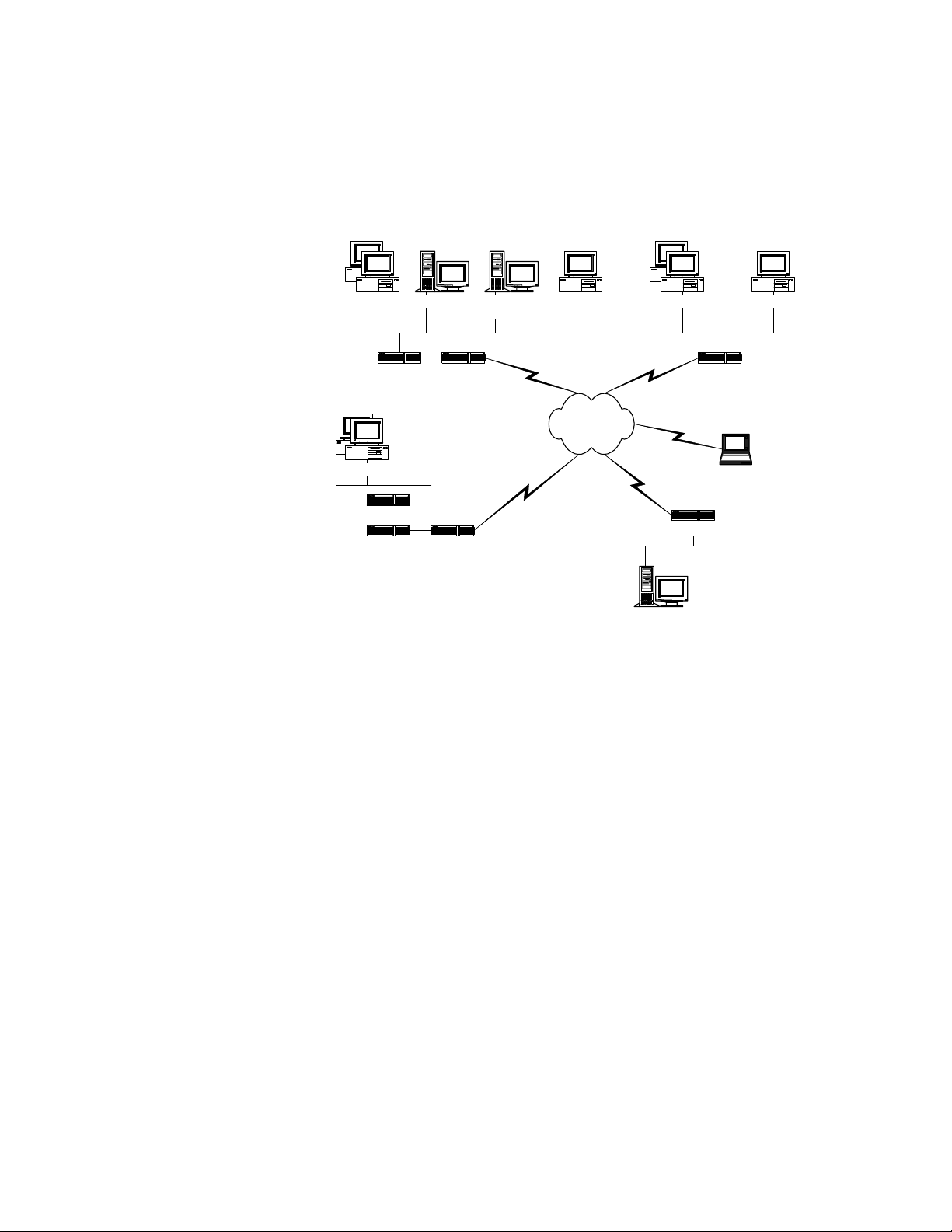
These components are illustrated next in a typical network
configuration.
Hewlett-Packard Company Virtual Private Networking Concepts Guide
1-3
Page 12
HP VPN Concepts Guide Overview
Branch or Supplier's Office
Related
Related
Related Related
Information
Information
InformationInformation
Office PCs
VPN Device
Office PCs
Existing
Server
Branch or Supplier's Office
VPN Device
Firewall
Figu r e : Typical Netw ork Configura t i on
Figu r e : Typical Netw ork Configura t i on
Figu r e : Typical Netw ork Configura t i onFigu r e : Typical Netw ork Configura t i on
(Mail, Web)
Router
Router
VPN ManagerServers
Internet
Operational Overview (page 1-5)
TCP/IP Basics Overview (page 1-6)
Office PCs
Servers
(Mail, Web)
Router
Laptop Computers
With modems
Router
Internet Sites
VPN Client
VPN Client
HP VPN Concepts Guide Overview (page1-1)
1-4 Hewlett-Packard Company Virtual Private Networking Concepts Guide
Page 13

Related
Related
Related Related
Information
Information
InformationInformation
Operational Overview
Operational Overview
Operational Overview
Operational OverviewOperational Overview
The VPN devices fit into typical network configurations in
various locations. VPN devices often sit at the gateway between
LANs and WANs. All data into and out of a protected LAN passes
through the VPN device for proces sing. The VPN Client software
package runs on PCs either directly connected to a LAN or
remotely located and connect to the WAN by means of a dial-up
connection.
VPN devic es are configu red by using the VPN Ma nager (which
runs on a Windows 95 or Win dows NT workstat ion), a command
line interface from a console, or through a Telnet sess ion from a
computer on the VPN's trusted netw or k.
HP VPN Conce pts Guide Overview (page1-1)
TCP/IP Basics Overview (page 1-6)
Hewlett-Packard Company Virtual Private Networking Concepts Guide
1-5
Page 14

HP VPN Concepts Guide Overview
TCP/IP Basics Over view
TCP/IP Basics Over view
TCP/IP Basics Over viewTCP/IP Basics Over view
The VPN devices operate on Transmission Control Protocol/
Internet Protocol (TCP/IP) ne tw orks . TCP/IP is the foundation
of the Internet. To fully appreciate how the VPN devices work,
you need to understand some basic TCP/IP terms.
Packe ts an d
Packe ts an d
Packe ts an d Packe ts an d
Packe t H e ade rs
Packe t H e ade rs
Packe t H e ade rsPack e t H e ade rs
Communications in a TCP/IP network are broken into small
chunks called packets. The typical maximum packet size carried
over TCP/IP networks is 1500 bytes. Each packet carries s o me
user data called payl oad. Th e payl oad could be part of an e- mail
message or a Web page. Every packet also has some control
information that i ndicates w here the packet origi nated, where it
is going, and what application should receive it when it arrives.
This information is referred to as the packet header. A simplified
packet example is shown in the following diagram.
Figure:
Figure: Simple Packet Diagram
Figure: Figure:
Simple Packet Diagram
Simple Packet DiagramSimple Packet Diagram
IP Address
IP Address All devices on a TCP/IP network must have at least one address
IP AddressIP Address
called an IP address. This address uniquely identifi es the device
on a network (actually in the entire world). For example, "Test
Company's" Web server has the following IP address:
205.250.128.2.
There are some reserved IP addresses that are never assigned,
which are called unroutable. Anyo ne can use these add resses on
a closed network. Well-known unroutable IP addresses start
with 10.x.x.x and 192. 168. x.x, w here x is an y n umb er between 1
and 254.
Subnet Mask
Subnet Mask One function of a subnet mask is to tell a device what other
Subnet MaskSubnet Mask
addresses it can directly communicate with. An example of a
subnet mask is 255.255.255.0, which defines a class C subnet.
Each component of the subnet mask (either 255 or 0 in the
example) is called an octet. A class C subnet mask means that
there are 254 addresses with which the device can directly
communicate.
1-6 Hewlett-Packard Company Virtual Private Networking Concepts Guide
Page 15

TCP/IP Basics Overview
For example, "Test C ompany" is assigned a full class C. This
means "Test Company" can use any address betwe e n
205.250.128.1 up to 205.250.128. 254. The addresses 205.250.128.0
and 205.250.128.255 are also part of the addresses in the class C
subnet, but are res erved for broadcasting and cannot be assigned
to any devices on the network (often called bo undar y
addresses).
If you want to break your clas s C into separate networks, y o u do
this by varying the last octet of the subnet mask. If you make
your subnet mask 255.255.255.128, your class C is split into 2
parts. This gives you one subnet containing the addresses from
205.250.128.1 to 205.250.128.126 and another subnet containing
205.250.128.129 to 205.250.128.254.
When you work with the full class C, there are 2 boundary
addresses reser ved for broadcasts. E very subnet requires 2
addresses for broadcasts. When you split your class C into 2
parts, you must still have broadcast ad dr esses in each subnet.
The first subnet uses 205.250.128.0 and 205.250.128.127 for
broadcasts while the second uses 205.250.128.128 and
205.250.128.255.
When you have the full class C, there are 254 addresses you can
use. Once the class C is split into two subnets, there are 126
addresses in each subnet for a total of 252 addresses.
The following values, if placed in the last octet of the subnet
mask, divide a class C subnet into smaller subnets.
Decimal Value
Decimal Value
Decimal Value Decimal Value
(Binary Value)
(Binary Value)
(Binary Value)(Binary Value)
Number of Subnets
Number of Subnets
Number of SubnetsNumber of Subnets
255 (1111-1111) 254 1
254 (1111-1110) 128 0
252 (1111-1100) 64 2
248 (1111-1000) 32 6
240 (1111-0000) 16 14
224 (1110-0000) 8 30
Hewlett-Packard Company Virtual Private Networking Concepts Guide
Number of
Number of
Number of Number of
Addresses in Each
Addresses in Each
Addresses in Each Addresses in Each
Subnet
Subnet
SubnetSubnet
1-7
Page 16

HP VPN Concepts Guide Overview
192 (1100-0000) 4 62
128 (1000-0000) 2 126
0 (0000-0000) 1 254
Note:
Note: If you d ivide your class C into more and mor e subnets, the
Note: Note:
number of available addresses becomes smaller and smaller.
Routing Table
Routing Table When a device creates a packet for transmission, it looks at the
Routing TableRouting Table
destina t ion IP address. If the address is on t he same su bn et as
the device (as defined by the subnet mask), the device looks for
the address on its LAN. If the destination device responds, the
originating device transmits the packet directly to the
destination. However, if the destination device is not found
locally, the originating de vice must decide what to do with the
packet.
The rules upon which the device bases the decision are called
routes, which are stored in a routing table. The routing table
maps network addresses to gateways. B asi cally, it tells the
device that if it has a packet dest ined for a certain network, the
packet should be sent to a specific gateway. The gateway can be
any device such as a router or a switch that can send the packet
out of the local subnet.
Static routes are entries in the routing table that do not change.
They are often defined on routers and switches when network
topologies become complex and the network administrator
wants to force packets to go in a certain k nown direc t ion (that
is, through a specif ic gateway ). Dynamic rou tes are e ntries in the
routing table that may change over time. This type of route is
usually added automatically, based on some network routing
protocol.
Default Gateway
Default Gateway The routing table usually has a route of last resort known as a
Default GatewayDefault Gateway
default gateway. The default gateway is where the originating
device sends any packet for which it has no specific rule in its
routing table. Most desktop computers do not have static routes
added to them and therefore rely on the default gateway being
set to be able to communicate outside t heir lo cal subnet. This
1-8 Hewlett-Packard Company Virtual Private Networking Concepts Guide
Page 17

TCP/IP Basics Overview
implies that the default gateway's IP address must be on the
same subnet as the originating device. Computers can directly
communicate only wit h devices on their local subnet (as defined
by their IP address and subnet mask).
Default gateways are what make the Internet work. When a
packet is created by a desktop computer destined for an address
on the Internet, the desktop computer often sends the packet to
its default gateway. The default gateway is often an edge router
connecting the LAN (on which the desktop computer is sitting)
to the Internet. The edge router probably does not have specific
routes telling it what to do with the packet. The edge router,
therefore, most l ikely sends the pack et off to its def ault gateway.
This cycle occurs until th e packet arrives at a devi ce that knows
where to find the destination address.
Application Port
Application Port When a computer (or an y network device) receives a packet, the
Application PortApplication Port
computer decides what to do with it. The computer may have
many different program s running simultane ously (for example, a
mail server and a Web server). Each program expecting to
receive or send packets from or to a network opens something
called a socket. If you look at an IP address as a street address
that identifies a building, then an open socket can be compared
to a room number within the building. The number given to a
socket is called an applica t i o n port number.
Each packet contains both a source application port and
destination application po rt in it s hea der. The destination
application port number is used by the receiving computer to
decide which pro gram should be given the payload of the packet
for final proce ssi ng.
Many application port numbers are standard. Some common
numbers ar e port 80, which is associated wit h http (www )
packets; port 25, wh ich is associated with SMTP mail; port 110
(POP3 mail); port 23 (Telnet); and port 21 (FTP). Therefore,
when Web servers start, they usually connect to port 80 and
listen for requests to come in. Note that a Web server can be
configured to listen on another port, but most follow the
standard.
Packets with the source and destination applic ati o n ports set to
2233 are encrypted with a HP VPN device.
Hewlett-Packard Company Virtual Private Networking Concepts Guide
1-9
Page 18

HP VPN Concepts Guide Overview
Related
Related
Related Related
Information
Information
InformationInformation
HP VPN Concepts Guide Overview (page1-1)
Operational Overview (page 1-5)
The Template Concept
1-10 Hewlett-Packard Company Virtual Private Networking Concepts Guide
Page 19

Cryptographic Systems and Encryption Terminology
Cryptographic Systems and Encryption Terminology
Cryptographic Systems and Encryption TerminologyCryptographic Systems and Encryption Terminology
Cryptographic Systems and Encryption Terminology Overview . . . . . . . . . . . . . . . . . 2-1
Symmetric Cryptographic Systems. . . . . . . . . . . . . . . . . . . . . . . . . . . . . . . . . . . . . . . . . . .2-3
Data Encryption Standard (DES) . . . . . . . . . . . . . . . . . . . . . . . . . . . . . . . . . . . . . . . . . . . .2-4
Triple Pass DES. . . . . . . . . . . . . . . . . . . . . . . . . . . . . . . . . . . . . . . . . . . . . . . . . . . . . . . . . . .2-5
3DES. . . . . . . . . . . . . . . . . . . . . . . . . . . . . . . . . . . . . . . . . . . . . . . . . . . . . . . . . . . . . . . . . . . .2-7
Outer Cipher Block Chaining (CBC) . . . . . . . . . . . . . . . . . . . . . . . . . . . . . . . . . . . . . . . . .2-8
Asymmetric Cryptographic Systems . . . . . . . . . . . . . . . . . . . . . . . . . . . . . . . . . . . . . . . . .2-9
Symmetric Vs. Asymmetric Cryptography. . . . . . . . . . . . . . . . . . . . . . . . . . . . . . . . . . . .2-10
Diffie-Hellman Session Key Exchange. . . . . . . . . . . . . . . . . . . . . . . . . . . . . . . . . . . . . . .2-11
Key Space and Brute Force Attacks. . . . . . . . . . . . . . . . . . . . . . . . . . . . . . . . . . . . . . . . .2-13
CC
Cr
C
rr
ry
yy
yp
pp
pt
tt
to
oo
og
gg
gr
rr
ra
aa
ap
pp
ph
hh
hi
ii
ic
cc
c
S
SS
Sy
yy
ys
ss
st
tt
te
ee
em
mm
ms
ss
s
a
aa
an
nn
nd
dd
d
E
EE
En
nn
nc
cc
cr
rr
ry
yy
yp
pp
pt
tt
ti
ii
io
oo
on
nn
n
T
TT
Te
ee
er
rr
rm
mm
mi
ii
in
nn
no
oo
ol
ll
lo
oo
og
gg
gy
yy
y
Hewlett-Packard Company Virtual Private Networking Concepts Guide
Page 20

yy
y
gg
gy
oo
og
ll
lo
oo
ol
nn
no
ii
in
mm
mi
rr
rm
ee
er
TT
Te
T
nn
n
oo
on
ii
io
tt
ti
pp
pt
yy
yp
rr
ry
cc
cr
nn
nc
EE
En
E
dd
d
nn
nd
aa
an
a
ss
s
mm
ms
ee
em
tt
te
ss
st
yy
ys
SS
Sy
S
cc
c
ii
ic
hh
hi
pp
ph
aa
ap
rr
ra
gg
gr
oo
og
tt
to
pp
pt
yy
yp
rr
ry
C
CC
Cr
Hewlett-Packar d Company Virtual Pri vate Networking Concepts Guide
Page 21

Cryptographic Systems and Encryption Terminology
Cryptographic Systems and E ncryption
2
Cryptographic Systems and E ncryption
Cryptographic Systems and E ncryption Cryptographic Systems and E ncryption
Terminology Overview
Terminology Overview
Terminology OverviewTerminology Overview
When Julius Caesar sent messages to his trusted acquaintances,
he did not trust the mes sengers. So he replaced every A with a D,
every B with an E, and so on throughout the alphabet. This was
the beginning of cryptography. Only those who knew the "shift
by 3" rule could decipher his messages.
A cryptographic system is a method of disguising messages so
that only certain people can see through the disguise.
Cryptography is the art of creating and using cryptographic
systems.
The original message is called a plaintext. The disguise d message
is called ciphertext. Encryption means any procedure to conver t
plaintext into ciphertext. Decryption means any procedure to
convert ciphertext into plaintext.
The term cryptographic system refers to a set of encryption and
decryption algorith ms. The algorithms are labeled and the labels
are called keys. For example, Caesar probably used "shift by n"
encryption for several different values of n. It is natural to say
that n is the key here.
Two general types of cryptograp hic systems exist: symmetric
cryptographic systems and asymmetric cryptographic systems.
Encryption
Encryption Encryption is a mathematical operation that transforms data
EncryptionEncryption
from cle a r te xt to cipher text. Us ually the math ema tical
operation requires that a key be supplied along with the clear
text.
Encryption, therefore, can be expressed as t he formula:
Cipher Text = f ( Clear Text , Ke )
In this formula, f represents some mathematical operati on or
algorithm and Ke represents a key.
Decryption is the opposite of encryption, a mathematical
operation that transforms cipher text to clear text. Decryption
usually requires a key and can be expressed as the formula:
Clear Text = g ( Cipher Text , Kd )
Hewlett-Packard Company Virtual Private Networking Concepts Guide 2-1
Page 22

Cryptographic Systems and Encryption Terminology
In this formula, g represents a mathematical operation, which
"undoe s" the s t eps per formed b y the algorithm f, and Kd
represents a key.
Related
Related
Related Related
Information
Information
InformationInformation
Symmetric Cryptographic Systems (page 2-3)
Asymmetric Cryptographic Systems (page 2-9)
Symmetric Vs. Asymmetric Cryptography (page 2-10)
2-2 Hewlett-Packard Company Virtual Private Networking Concepts Guide
Page 23

Symmetric Cryptographic Systems
Symmetric Cryptographic Sys tems
Symmetric Cryptographic Sys tems
Symmetric Cryptographic Sys temsSymmetr ic Cr yptographic Sys tems
A very simple encryption algorithm involves shifting the letters
of the alphabet to the right by some offset. For example if you
had the clear text "AT" and decided to encrypt this data by
shifting each letter 3 letters to the right, you would end up with
DW. In this example, the clear text is AT, the key is 3, the
algorithm is "shift K letters to the right," and the cipher text i s
DW. Your encryption formula would look like this:
DW = shift-right ( AT , 3 )
Of course, decryption in this case involves shifting the letters of
the cipher text to the left by the same offset used when the data
was encrypted. Therefore, your decryption formula would look
like this:
AT = shift-left ( DW , 3 )
Note that the key used to encrypt the data is the same key used
to decrypt the data.
Ke = Kd
This algorithm is therefore referred to as symmetric. In this case,
the person encrypting the data and the person decrypting the
data must both know the same key. The strength of the system
relies on the key being kept secret. Symmetric cryptography is
therefore often referred to as secret key cryptography.
A real world metaphor for symmetric cryptography is a lock box
with a single lock. To safely transfer an object from one person
to another, the first person opens the box with a key, puts the
object in the box, and then locks the box. The second person
needs only a copy of the key, and can then open the box and
retrieve the object.
Related
Related
Related Related
Information
Information
InformationInformation
Hewlett-Packard Company Virtual Private Networking Concepts Guide
Data Encryption Standard (DES) (page 2-4)
Triple Pass DES (page 2-5)
3DES (page 2-7)
2-3
Page 24

Cryptographic Systems and Encryption Terminology
Data Encryption Standard (DES)
Data Encryption Standard (DES)
Data Encryption Standard (DES)Data Encryption Standard (DES)
The Data Encryption Standard (DES) is a well-known and
thoroughly tested cryptographic system. The DES algorithm is a
very complex symmetric algorithm that specifies that data be
encrypted in 64-bit b lo cks . A 64-bit block of clear text goes into
the algorithm al ong with a 56-bit ke y. The resul t is a 64-b it block
of cipher text. Since the key size is fixed at 56 bits, the number
of keys available (the key space) is 256 different keys (about
72,000,000,000,000,000 keys). This is a huge increase over the
size of the key space in simple cryptographic systems.
A recent report by a group of scientists from AT&T Research,
Sun Microsystems, the MIT Laboratory for Computer Science,
the San Diego Supercomputer Center, Bell Northern Research
and others, entitled "Minimal Key Lengths for Symmetric
Ciphers to Provi de Adequate Commercial S ecurity (Blaze, Dif fie,
Rivest, Schneier, Shimomura, Thompson and Wiener)" found
that a pedestrian hacker with US $400 to spend requires about 38
years of effort to decode data encrypted with DES with its large
key space. Unfortunately, they also determined that a large
organization with US $300 million to spend could crack a 56-bit
key space in about 12 seconds, using brute force techniques.
They estimate that a 90-bit key protects data for about 20 years
in the face of expected advances in computing power.
Related
Related
Related Related
Information
Information
InformationInformation
2-4 Hewlett-Packard Company Virtual Private Networking Concepts Guide
Triple Pass DES (page 2-5)
3DES (page 2-7)
Outer Cipher Block Chaining (CBC) (page 2-8)
Page 25

Triple Pass DES
Triple P ass DES
Triple P ass DES
Triple P ass DESTriple P ass DES
Triple Pass DES is a cryptographic system that uses multiple
passes of the DES algorithm to increase the effective key space
available to the system. In triple pass DES, the clear text data is
first encrypted with a 56-bit key. The resul ting cipher text is th en
decrypted with a different key. Decrypting cipher text w i th the
wrong key will result in unreadable data. Finally the unread able
data is encrypted again wi th the first key. This implementatio n of
triple pass DES is known as EDE (for Encr ypt, Decrypt, Encrypt)
and the technique increases the effective key len gth from 56 bits
to 112 bits. Note that 90-bit keys should protect encrypted data
for about 20 years.
Go back to the simple Symmetric Cryptographic Systems
(page 2-3) to illustrate the EDE technique. Assuming that the
,
clear text is AT
1. Encrypt with the key set to 3.
DW = shift-right( AT , K1 = 3 )
2. Decrypt the result DW with a different key (for example, 5 ).
YR = shift-left( DW , K2 = 5 )
Note that the result in this case is not the original clear text.
Now encrypt the result YR wi th the key used in the first step.
BU = shift-right( YR , K1 = 3 )
the following steps are involved:
The final cipher text is BU. When this cipher text is received, the
decoding process must be performed in reverse (DED). The
decoder must know the 2 keys (K1 = 3 and K2 = 5) and then make
3 passes:
1. Decrypt with the key set to 3.
YR = shift-left( BU , K1 = 3 )
2. Encrypt with the key set to 5.
DW = shift-right( YR , K2 = 5 )
3. Decrypt with the key set to 3.
AT = shift-left( DW , K1 = 3 )
The steps for both the triple pass DES technique and the 3DES
technique are illustrated with the simple symmetric
cryptographic system in the following table.
Hewlett-Packard Company Virtual Private Networking Concepts Guide
2-5
Page 26

Cryptographic Systems and Encryption Terminology
Algorithm
Algorithm
AlgorithmAlgorithm
Clear
Clear
Clear Clear
Text
Text
TextText
After
After
After After
First
First
First First
Encrypt
Encrypt
Encrypt Encrypt
EEEE
After
After
After After
First
First
First First
Decrypt
Decrypt
Decrypt Decrypt
DDDD
After
After
After After
Second
Second
Second Second
Encrypt
Encrypt
Encrypt Encrypt
EEEE
Related
Related
Related Related
Information
Information
InformationInformation
Triple Pass DES
(Key Space = 2*26
AT K1 = 3
DW
=52)
3DES
(Key Space = 3*26
AT K1 = 3
DW
=78)
3DES (page 2-7)
Data Encryption Standard (DES) (page 2-4)
Outer Cipher Block Chaining (CBC) (page 2-8)
K2 = 5
YR
K2 = 5
YR
K1 = 3
BU
K3 = 4
CV
2-6 Hewlett-Packard Company Virtual Private Networking Concepts Guide
Page 27

3DES
3DES
3DES3DES
3DES is a symmetric cryptographic system that uses multiple
passes of the DES algorithm to increase the effective key space
available to the system even further than triple pas s DES. Use the
same EDE technique as in Triple Pass DES (page 2-5), except
that 3 different keys are u sed. Therefore, in pass 3 of Triple Pass
DES, you would sel ect a third key (K3 = 4), which increases the
effective key length from 56 bits for simple DES to 168 bits for
3DES.
The steps for both the triple pass DES technique and the 3DES
technique are illustrated with the simple symmetric
cryptographic system in the following table.
After
Algorithm
Algorithm
AlgorithmAlgorithm
Clear
Clear
Clear Clear
Text
Text
TextText
After
After After
First
First
First First
Encrypt
Encrypt
Encrypt Encrypt
EEEE
After
After
After After
First
First
First First
Decrypt
Decrypt
Decrypt Decrypt
DDDD
3DES
After
After
After After
Second
Second
Second Second
Encrypt
Encrypt
Encrypt Encrypt
EEEE
Related
Related
Related Related
Information
Information
InformationInformation
Triple Pass DES
(Key Space = 2*26
AT K1 = 3
DW
=52)
3DES
(Key Space = 3*26
AT K1 = 3
DW
=78)
Data Encryption Standard (DES) (page 2-4)
Outer Cipher Block Chaining (CBC) (page 2-8)
K2 = 5
YR
K2 = 5
YR
K1 = 3
BU
K3 = 4
CV
Hewlett-Packard Company Virtual Private Networking Concepts Guide
2-7
Page 28

Cryptographic Systems and Encryption Terminology
Outer Cipher Block Chaining (CBC)
Outer Cipher Block Chaining (CBC)
Outer Cipher Block Chaining (CBC)Outer Cipher Block Chaining (CBC)
Outer Cipher Block Chain ing or outer-CBC is a techni que used to
further strengthen the DES, triple pass DES, and 3DES
algorithms. This technique involves injecting random spoiler
data into the encryption algo rithm so that identical blocks of
clear text d oes not resul t in the s ame cipher text even if the same
key is used repeatedly. Therefore, if the clear text s tri ng " A T" is
encrypted a thousand times with the same key, the resulting
cipher text would be different each time. This is important since
most file structures and application protocols use identical
header information.
Related
Related
Related Related
Information
Information
InformationInformation
Data Encryption Standard (DES) (page 2-4)
Triple Pass DES (page 2-5)
3DES (page 2-7)
2-8 Hewlett-Packard Company Virtual Private Networking Concepts Guide
Page 29

Asymmetric Cryptographic Systems
Asymmetric Cryptographic Systems
Asymmetric Cryptographic Systems
Asymmetric Cryptographic SystemsAsymmetric Cryptographic Systems
Some algorithms do not use the same key to encrypt and d ecrypt.
These algorithms are referred to as asymmetric, are usually
complex, and often rely on the properties of very large prime
numbers. A simple asymmetric algorithm, similar to the
symmetric example, uses the same formula for encryption:
DW = shift-right ( AT , 3 )
In the symmetric examp le the encryption was "undone" usin g the
mathematical operation of "shift-left." If you change the
decryption operatio n to "shift- righ t," you need a di ffere n t key to
arrive back at the clear text:
AT = shift-right ( DW , -3 )
Note that the key used to decrypt the cipher text in this case is
different from the key used to encrypt th e clear text. T he keys,
however, are related. The relationship between the keys in the
simple asymmetric algorithm can be expressed:
Ke = -1 * Kd
When asymmetric cryptography is used, the person doing the
encrypting does not need to know the same key as the person
doing the decrypting.
Asymmetric cryptography is often referred to as a public key
cryptography. The public and private keys used in asymmetric
cryptography are sometimes called key pairs, and are always
related through some mathematical operation.
Related
Related
Related Related
Information
Information
InformationInformation
Hewlett-Packard Company Virtual Private Networking Concepts Guide
Symmetric Cryptographic Systems (page 2-3)
Symmetric Vs. Asymmetric Cryptography (page 2-10)
Key Space and Brute Force Attacks (page 2-13)
2-9
Page 30

Cryptographic Systems and Encryption Terminology
Symmetric Vs. Asymmetr ic Cryptogra phy
Symmetric Vs. Asymmetr ic Cryptogra phy
Symmetric Vs. Asymmetr ic Cryptogra phySymmetric Vs. Asymmetr ic Cryptogra phy
Symmetric and asymmetric cryp tograph y have some significant
differences. Symmetric cryptography tends to be fast compared
to asymmetric cryptography. Therefore, symmetric algorithms
are often used when large quantities of data need to be
exchanged and the 2 parties are known to each other.
Conversely, a symm et ric algorithms are used when small
quantities of data need to be exchanged or the 2 parties are not
known to each other.
Asymm et r ic cryptogr aphy is often used during authentication
processes. Another significant di fference between the 2 types of
cryptographic systems is the length of the keys required by the
algorithms. The keys used in symmetric algorithms are usually
much smaller than those used in asymmetric algorithms, as
described in the following table.
Speed Fast Slow
Symmetric
Symmetric Asymmetric
SymmetricSymmetric
Asymmetric
AsymmetricAsymmetric
Key size Relatively small Extremely large
Key usage Shared secret Public/private
Usual usage Bulk data transfer Authentication
Examples DES, Triple Pass
DES, 3DES, rc4
Related
Related
Related Related
Information
Information
InformationInformation
2-10 Hewlett-Packard Company Virtual Private Networking Concepts Guide
Asymmetric Cryptographic Systems (page 2-9)
Symmetric Cryptographic Systems (page 2-3)
Key Space and Brute Force Attacks (page 2-13)
RSA, PGP
Page 31

Diffie-Hell man Session Key Exchange
Diffie-Hellman Session K ey Exchange
Diffie-Hellman Session K ey Exchange
Diffie-Hellman Session K ey ExchangeDiffie-Hellman Session K ey Exchange
The Diffie-Hellman key exchange protocol is based on an
asymmetric algorithm. In asymmetric cryptographic systems,
the key used to encrypt data is different from the key used to
decrypt it. The key used to encrypt the data is usually referred to
as a public key, while the key used to decrypt the data is called
the private key, and the public key is derived from the private
key. The length of the public and private keys can be 512 bits,
1024 bits, or 2048 bits.
The problem of key exchange between VPN devices is solved
using a protocol known as the Diffie-Hellman key exchange
protocol. This protocol must be followed whenever two VPN
devices first begin to communicate, or when a session key
expires. The strength of this protocol is that it allows the two
devices to negotiate or deci de on a common session key with out
ever exchanging the key.
In general, when two devices exchange some data using an
asymmetric cryptographic system, each device first requests the
public key of the other device. They then use the public key of
the other device to encrypt the data. When the other device
receives the data, it can then use its private key to decrypt the
data. As the name suggests, public keys are not secret and are
made known to any device that requests them. Private keys,
however, should never be revealed or distributed.
The Diffie-Hellman protocol specifies that the two devices
negotiating a common session key should each select half of a
session key. They must also each derive some parameters that
can be used to calculate the same half-session key. It is these
parameters that are exchanged using the public/private key
technique. Once the parameters are exchanged, then the secon d
half of the session key can be calculated.
Notice that the session keys are never actually exchanged. The
parameters for calculating half a session key are sent. To derive
the full session k ey, both packets must be trapped and then
broken. The effort required to break keys with lengths of 512,
1024, or 2048 bits makes this attack impractical.
The vulnerability of this type of key exchange protocol is the
public key exchange.
Hewlett-Packard Company Virtual Private Networking Concepts Guide
2-11
Page 32

Cryptographic Systems and Encryption Terminology
Crypto Perio d
Crypto Perio d A crypto period defines how long a session key is actually used.
Crypto Perio dCrypto Perio d
Key lifetimes (crypto-periods) affect encryption strength
because the longer the same session key is used the greater the
chance that it is compromised. Additionally, the more data that
is secured with a given key, the greater the loss if the key is
compromised.
Long crypto-periods (key lives) also provide more ammunition
for an adversary to break the key since the adversary potentially
has access to significantly more data to work with. Finally, the
longer a key is in use, the greater the temptation to break the
keys since breaking the key provides the adversary with access
to significantly more valuable data.
Related
Related
Related Related
Information
Information
InformationInformation
Triple Pass DES (page 2-5)
3DES (page 2-7)
Packet Keys (page 3-8)
2-12 Hewlett-Packard Company Virtual Private Networking Concepts Guide
Page 33

Key Space and Brute Force Attacks
Key Space and Brute Force Attacks
Key Space and Brute Force Attacks
Key Space and Brute Force AttacksKey Space and Brute Force Attacks
Before reading this section, review Symmet ric C r yptographic
Systems (page 2-3) and Asymmetric Cryptographic Systems
(page 2-9).
Key Space
Key Space In the simple cryptographic systems, up to 26 different possible
Key SpaceKey Space
keys can be selected. The keys availa ble range from 1 to 26 since
there are 26 letters in the alphabet. If 27 is used as your key, it
would produce the same cipher text as if 1 was selected for your
key. Therefore, your key space contains exactly 26 keys.
The longer the key length, the more possible combinations a
potential code-breaker would have to test. The following table
shows the number of possibilities for common key length
(Source: FreeMarket.Net: Policy Spotlight, October -Nov ember
1997).
Key Length
Key Length Possible Keys
Key LengthKey Length
40 bits 1,099,511,627,776
Possible Keys
Possible KeysPossible Keys
56 bits 72,057,594,037,927,900
90 bits 1,237,940,039,285,380,000,000,000,000
128 bits 340,282,366,920,938,000,000,000,000,000,000,000,000
Brut e F or ce
Brut e F or ce
Brut e F or ce Brut e F or ce
Attacks
Attacks
AttacksAttacks
Related
Related
Related Related
Information
Information
InformationInformation
Hewlett-Packard Company Virtual Private Networking Concepts Guide
A brute force attack captures some cipher text and then tries all
26 different possible keys. Given enough cipher text, a brute
force attack could be quite effective. Obviously, if you can
increase the number of different keys available, brute force
attacks become correspondingly more difficult or time
consuming. The trick is to find an algorithm that allows for an
extremely large number of keys. The higher the key space, the
more difficult the encryption is to break.
Symmetric Cryptographic Systems (page 2-3)
Asymmetric Cryptographic Systems (page 2-9)
2-13
Page 34

Cryptographic Systems and Encryption Terminology
Symmetric Vs. Asymmetric Cryptography (page 2-10)
2-14 Hewlett-Packard Company Virtual Private Networking Concepts Guide
Page 35

Encapsulation and Packet Handling
Encapsulation and Packet Handling
Encapsulation and Packet HandlingEncapsulation and Packet Handling
Encapsulation Overview . . . . . . . . . . . . . . . . . . . . . . . . . . . . . . . . . . . . . . . . . . . . . . . . . . 3-1
Secure Profiles . . . . . . . . . . . . . . . . . . . . . . . . . . . . . . . . . . . . . . . . . . . . . . . . . . . . . . . . . . .3-2
ESP Encapsulation . . . . . . . . . . . . . . . . . . . . . . . . . . . . . . . . . . . . . . . . . . . . . . . . . . . . . . . .3-4
SST Encapsulation . . . . . . . . . . . . . . . . . . . . . . . . . . . . . . . . . . . . . . . . . . . . . . . . . . . . . . . .3-6
Packet Handling . . . . . . . . . . . . . . . . . . . . . . . . . . . . . . . . . . . . . . . . . . . . . . . . . . . . . . . . . .3-7
Packet Keys . . . . . . . . . . . . . . . . . . . . . . . . . . . . . . . . . . . . . . . . . . . . . . . . . . . . . . . . . . . . . .3-8
EE
En
E
nn
nc
cc
ca
aa
ap
pp
ps
ss
su
uu
ul
ll
la
aa
at
tt
ti
ii
io
oo
on
nn
n
a
aa
an
nn
nd
dd
d
P
PP
Pa
aa
ac
cc
ck
kk
ke
ee
et
tt
t
H
HH
Ha
aa
an
nn
nd
dd
dl
ll
li
ii
in
nn
ng
gg
g
Hewlett-Packard Company Virtual Private Networking Concepts Guide
Page 36

gg
g
nn
ng
ii
in
ll
li
dd
dl
nn
nd
aa
an
HH
Ha
H
tt
t
ee
et
kk
ke
cc
ck
aa
ac
PP
Pa
P
dd
d
nn
nd
aa
an
a
nn
n
oo
on
ii
io
tt
ti
aa
at
ll
la
uu
ul
ss
su
pp
ps
aa
ap
cc
ca
nn
nc
E
EE
En
Hewlett-Packar d Company Virtual Pri vate Networking Concepts Guide
Page 37

3
Related
Related
Related Related
Information
Information
InformationInformation
Encapsulation an d Packet Handling
Encapsulation Overview
Encapsulation Overview
Encapsulation OverviewEncapsulation Overview
There are two types of encapsulation available with HP VPN
products. The first is Shiva Smart Tunneling (SST)
encapsulation. The secon d, called Encapsulating Security
Payload (ESP) enc apsulation, is an emerging standard as d efined
by IPSec. ESP (both 32- or 64-bit vers ions) shoul d be used wh en
you communicate with another non–HP VPN device (such as a
firewall or router) that has implemented the ESP portion of the
IPSec standard.
Encapsulation works in the following manner: when a packet is
encrypted, a brand new packet is created. This new packet
contains the entire ori ginal packet (inclu ding the header), which
has been encrypted, a new header, and some information
required by the device that finally decrypts the packet. The
original packet is said to be encapsulated.
Secure Profiles (page 3-2)
ESP Encapsulation (page 3-4)
SST Encapsulation (page 3-6)
Hewlett-Packard Company Virtual Private Networking Concepts Guide 3-1
Page 38

Encapsulation and Packet Handling
Secure Profiles
Secure Profiles
Secure ProfilesSecure Profiles
Secure profiles are used to define how packets are encrypted
when passing t hrough a tunnel an d how the estab lishment of the
communication session is authenticated. Secure profiles must
contain the following information to be complete.
Name
Name The name is a descripti ve alphanum eric string used to referen ce
NameName
the secure profile when it is applied to a tunnel. Although no
naming convention is imposed, it is wise to define one prior to
creating your profiles. Suggested naming conventions indicate
either the intended use of th e profile (for example , Interoffice or
Dial-up user), the relative strength of the profile (for example,
Strict or Ver y Strict), or the c ontents of t he p rofile (fo r exampl e,
ESP-3DES-K1024-C12HRS for ESP encapsulation, 3DES,
authentication key wit h 1024-bit public keys, and a crypto period
of 12 hours).
Algorithm
Algorithm The algorithm can be set to Data Encryption Standard (DES),
AlgorithmAlgorithm
Triple Pass DES, 3D ES, or 40-bi t DES for ESPv2 ( IPSec) tunnels.
Keepalive
Keepalive The keepalive interval can be set between 1 and 299 seconds or
KeepaliveKeepalive
disabled (0). T he keepalive feature is u sually specified in p rofiles
that are ap pl ied to rem o t e links a nd has two main uses . The first
is to ensure that the link status displayed on the remote VPN
device accurately r eflects the status o f the tunn el. The second is
to ensure that other VPN device s can sense that a remote device
has dropped its connection and therefore the tunnel must be
renegotiated. Note that setting the keepalive to a small value
causes many keepalive packets to be sent. This may impact the
responsiveness of the remo te connec tion.
Timeout
Timeout The keepalive timeout can be set between 2 and 300 seconds.
TimeoutTimeout
This specifies how long a VPN device should wait for a packet
from an opposing VPN device before declaring the session
terminated and attempting to renegotiate the tunnel. If you
specify a timeout on one end of a tunnel, you must specify a
keepalive on the other end of the tunnel.
3-2 Hewlett-Packard Company Virtual Private Networking Concepts Guide
Page 39

Secure Profiles
Encapsulation
Encapsulation The encapsulation can be set to either Shiva Smart Tunneling
EncapsulationEncapsulation
(SST) Encapsulation or to Encapsulating Security Payload (ESP)
Encapsulation. ESP is the security po rtion of th e IPSec stan dard.
SST encapsulation is recommended for data exchange between
VPN devices, as it is stronger than ESP encapsulation.
ESP (either version) should be used when you communicate
with another non–HP VPN device (such as a firewall or router)
that ha s impleme nt e d the ESP po rtion of the IPSe c st andard.
The E SP implementation in all HP VPN devices is tunnel mod e.
However, you can use transport mode by selecting ESP (either
version), setting the ESP authenticatio n to none, and selecti ng a
value for the Authentication Header (AH). Transport mode
encrypts only the payload.
Related
Related
Related Related
Information
Information
InformationInformation
SST Encapsulation (page 3-6)
ESP Encapsulation (page 3-4)
Encapsulation Overview (page 3-1)
Hewlett-Packard Company Virtual Private Networking Concepts Guide
3-3
Page 40

Encapsulation and Packet Handling
ESP Encapsula tion
ESP Encapsula tion
ESP Encapsula tionESP Encapsula tion
When the encapsulat ion is set to Encapsulating Secu rity Payload
(ESP), tun nel mode, t he follo wing in formation m ust be specified
to fully define the security profile.
IV Length
IV Length
IV Length IV Length
(Encapsulation)
(Encapsulation)
(Encapsulation)(Encapsulation)
Authentication
Authentication
Authentication Authentication
Header
Header
HeaderHeader
The iv (initialization vector) length must be set to either 32 bits
or 64 bits. This value is used during the outer cipher block
chainin g oper ation to e n sur e t hat the same packet encrypte d
multiple times wil l not generate the same cipher text. Bot h 32-bit
and 64-bit iv's offer the same level of randomness, but 32- bit iv's
use more system CPU and less bandwidth while 64-bit iv's use
less CPU and more bandwidth. The actual difference in CPU
usage and bandwidth usage is very small, and the industry
tendency is to use a 64-bit iv length.
This value can be set to keyed MD5, H MA C MD5 , keyed SHA 1,
HMAC SHA1, or none. An authentication header (AH) is added
to an ESP encapsulated packet (either version) to ensure that
the packet is not altered during transmissi on, and is constructed
by hashing the entire encrypted packet.
Setting the AH type specifies which algorithm to use for hashing.
The SHA1 hashing a lgorithm is slightly more secure t han MD5,
but also slightly slower. MD5 adds 16 bytes of overhead to each
packet, while SHA1 adds 20 bytes overhead. HMAC MD5 and
SHA1 are slightly more secure than keyed MD5 and SHA1
respe c t ivel y. Onc e again, the differences are marginal.
Ensure that the device on the other end (the firewall or router)
conforms to the IPSec standards to ensure its interoperability
with a VPN device.
AH Key Length
AH Key Length If you select either keyed MD5 or keyed SHA1 for your
AH Key LengthAH Key Length
authentication header t ype, the value must be s et bet ween 0 and
55 bytes. If you select either HMAC MD5 or HMAC SHA1 for your
authentication header (AH) type , the value must be set between
0 and 64 bytes. This value specifies the length of the key to be
used when hashing the packet to produce the authentication
header. The longer the key, the more secure the authentication,
but the more time-consuming to manually enter.
3-4 Hewlett-Packard Company Virtual Private Networking Concepts Guide
Page 41

Related
Related
Related Related
Information
Information
InformationInformation
ESP Encapsulation
SST Encapsulation (page 3-6)
Packet Handling (page 3-7)
Packet Keys (page 3-8)
Hewlett-Packard Company Virtual Private Networking Concepts Guide
3-5
Page 42

Encapsulation and Packet Handling
SST Encapsulation
SST Encapsulation
SST EncapsulationSST Encapsulation
When the encapsulation is set to Shiva Smart Tunneling (SST),
the following information must be specified to fully define the
security profile.
Authentication
Authentication
Authentication Authentication
Method
Method
MethodMethod
Public Key
Public Key
Public Key Public Key
Length
Length
LengthLength
Crypto Period
Crypto Period
Crypto Period Crypto Period
Length
Length
LengthLength
The authentication method must be set to either certificates,
challenge phrases, SecurID, or RADIUS. Challenge phrases are
often referred to as authentication keys. Sometimes challenge
phrases are called passwords, but th is is not a good synonym.
The public key length must be set to 512 bits, 1024 bits, or 2048
bits. Note that public keys are used during the authentication
and session key exchange processes. The longer the public key
length, the more secure the session negotiation will be.
The crypto period length defines how long a session key will be
used. The default value for the crypto period is 1 month,
although it can be set to as low as 3 hours. Given that a packet
encrypted with a 90-bit key will require about 20 years of effort
by a well-funded dedicated adversary to crack, it is often
sufficient to use the default value for crypto period length.
Related
Related
Related Related
Information
Information
InformationInformation
3-6 Hewlett-Packard Company Virtual Private Networking Concepts Guide
ESP Encapsulation (page 3-4)
Packet Handling (page 3-7)
Packet Keys (page 3-8)
Page 43

Packet Handling
Packet Handling
Packet Handling
Packet HandlingPacket Handling
When a computer or network device communicates over a
network (either a LAN or a WAN such as the Internet), the
devices all perform similar functions. The application program
(for example, a mail program) formulates a message, which is
then passed to a set of functions collectively known as the TCP/
IP stack. The TCP/IP stack looks at the message to determine if
it needs to be sent out of the computer and then breaks the
message into small packets and adds some header infor mat ion
to each packet.
The header information includes the following information:
• The destination addre ss o f the packet (the IP address of the mail
server)
• The application port on the destination computer (for
example, port 25 indicates that a SMTP mail server should be
the application listening at the destination address)
• The source address of the sender (the IP address of the
computer where the e-mail client is running)
• The application port that the sending machine used (usually
randomly assigned)
• The protocol used (for SMTP mail, the protocol is TCP)
The maximum size of these packets including the header is
usually 1500 bytes. Therefore, if your e-mail message is longer
than 1500 bytes (1500 characters), it will be broken into several
packets before being sent to the network layer and f in ally bein g
transmitted onto the network. A si mplified packet as released by
the TCP/IP stack is shown next.
DestIPSrc
IP
Related
Related
Related Related
Information
Information
InformationInformation
Hewlett-Packard Company Virtual Private Networking Concepts Guide
Packet Keys (page 3-8)
Encapsulation Overview (page 3-1)
Dest
Port
Figure: Simplified Packet
Figure: Simplified Packet
Figure: Simplified PacketFigure: Simplified Packet
Src
Port
Prot Payload Data
3-7
Page 44

Encapsulation and Packet Handling
Packet Keys
Packet Keys
Packet KeysPacket Keys
The key (or keys in the case of trip le pass DE S or 3DES) use d to
encrypt a packet in SST encapsulation is called a packet key. A
new packet key is randomly generated for every packet. This
step, along with the ou ter-CBC technique, ensures that no matter
how many ident ical original pa ckets are sent, t he new encrypted
packets are significan tly different each t ime. A simplified packet
as released by a VPN device is shown next.
Dest
Enc IP
Source and Destination
ports set to 2233
Dest
Src
Port=
Enc IP
2233
Source and destination
IPs set to encryptor IPs
Src
Port=
2233
Protocol
set to UDP
DestIPSrcIPDest
Prot=
UDP
Figure:
Figure: Encrypted Packet
Figure: Figure:
Encrypted Packet
Encrypted PacketEncrypted Packet
Original packet encrypted
with packet key
Src
Port
Port
Prot Payload Data
Packet keys encrypted
with session keys
Pck
Keys
This new packet has many interesting features. Note that the
destination and source IP addresses of the original packet are
different from the destination and source IP addresses of the
new packet. The new IP addresses are the IP addresses of the
VPN device that encrypted the packet. In many cases, these
addresses are the IP addresses of the WA N interfaces of t he VPN
device that secure the communication.
In a typical network configuration, a packet traveling from the
Web server at the main office to a PC on the Branch office
network has the IP addresses set t o the WAN side IP addresses
of the VPN devices at the gateways to these networks. The IP
address of the Web server and the PC are hidden from anyone
intercepting the packet and the interceptor gains no knowledge
about the LANs.
Note also that the destination and source ports are both set to
2233. This application port number i nd icates only that the
packet is encrypted. The source port in the original packet
would be set to port 80 to indi cate th at this i s World W i d e Web
traffic. Therefore, the nature of the packet is hidden from
anyone intercepting the packet.
The protocol has been modified and set to UDP. The original
packet, if it was an http (www) packet, has its protocol set to
3-8 Hewlett-Packard Company Virtual Private Networking Concepts Guide
Page 45

Packet Keys
TCP and indicates to an intruder that an ackn owledgment packet
is expected. Trapping acknowl edgment packets is a good way to
gain some knowledge of the contents of an encrypted packet,
which can be used to help break the encryption. Setting all the
encrypted packet p rot o co ls to UDP rem ove s this b it of
knowledge and further secures the communication.
The entire original packet is encrypted. Some other solutions
only encrypt the payload data and expose a wealth of
information about the nature of the packet and the source and
destinati o n networks .
Finally, the packet keys are encrypted with session keys and
appended to the new packet. Remember that DES, triple pass
DES, and 3DES are symmetric algorithms. Therefore, both the
device encrypting the packet and the device decrypting the
packet must know the s ame keys. The packet ke ys, however, are
randomly generated for each packet. Assuming that both the
encryptor and the decryptor know the same session keys, this
technique makes the encryption more secure in 2 ways. Attempts
to break the packet keys are not practical since it changes with
every packet. The most that can be gained is about 1400 bytes of
data from an operation that will take years. The session keys are
used to encrypt a very small amount of data (only the packet
keys), which is random. If the session keys are changed
periodically, then even this small target is moving and attacks
are made more difficult. The frequency with which session keys
are changed is called the crypto period.
Related
Related
Related Related
Information
Information
InformationInformation
Hewlett-Packard Company Virtual Private Networking Concepts Guide
Packet Handling (page 3-7)
The Template Concept
3-9
Page 46

Encapsulation and Packet Handling
3-10 Hewlett-Packard Company Virtual Private Networking Concepts Guide
Page 47

Authentication Methods
Authentication Methods
Authentication MethodsAuthentication Methods
Authentication Methods Overview. . . . . . . . . . . . . . . . . . . . . . . . . . . . . . . . . . . . . . . . . . 4-1
Certificate Authentication . . . . . . . . . . . . . . . . . . . . . . . . . . . . . . . . . . . . . . . . . . . . . . . . . .4-2
Challenge Phrase Authentication . . . . . . . . . . . . . . . . . . . . . . . . . . . . . . . . . . . . . . . . . . . .4-3
SecurID Authentication . . . . . . . . . . . . . . . . . . . . . . . . . . . . . . . . . . . . . . . . . . . . . . . . . . . .4-4
RADIUS Authentication. . . . . . . . . . . . . . . . . . . . . . . . . . . . . . . . . . . . . . . . . . . . . . . . . . . .4-5
Entrust Authentication. . . . . . . . . . . . . . . . . . . . . . . . . . . . . . . . . . . . . . . . . . . . . . . . . . . . .4-6
AA
Au
A
uu
ut
tt
th
hh
he
ee
en
nn
nt
tt
ti
ii
ic
cc
ca
aa
at
tt
ti
ii
io
oo
on
nn
n
M
MM
Me
ee
et
tt
th
hh
ho
oo
od
dd
ds
ss
s
Hewlett-Packard Company Virtual Private Networking Concepts Guide
Page 48

ss
s
dd
ds
oo
od
hh
ho
tt
th
ee
et
MM
Me
M
nn
n
oo
on
ii
io
tt
ti
aa
at
cc
ca
ii
ic
tt
ti
nn
nt
ee
en
hh
he
tt
th
uu
ut
A
AA
Au
Hewlett-Packar d Company Virtual Pri vate Networking Concepts Guide
Page 49

4
Related
Related
Related Related
Information
Information
InformationInformation
Authentication Methods
Authentication Methods Overview
Authentication Methods Overview
Authentication Methods OverviewAuthentication Methods Overview
An authentication method defines how an HP VPN device
validates the identity of another device. The identity of a device
includes its n a me , its IP address, and its p u bli c k ey. Wh en the
packet encapsul ation type is se t to Shiva Smart Tunneling (SST),
there are five possible authentication methods:
• Certificates by means of the certificate authority
• Challenge Phrase
• SecurID
• RADIUS
• Entrust by means of the Entrust Certificate Authority
Challenge Phrase Authentication (page 4-2)
SecurID Authentication (page 4-3)
RADIUS Authentication (page 4-4)
Entrust Authentication (page 4-5)
Hewlett-Packard Company Virtual Private Networking Concepts Guide 4-1
Page 50

Authenticat ion Methods
Certificate Authentication
Certificate Authentication
Certificate AuthenticationCertificate Authentication
The first thing that two VPN devices d o when they enter into a
communication is to exchange their certificates. Next, they
verify the authenticity of the certificates by ensuring that:
• The identifying information and the digital signature are
separated.
• A new MD5 digest of the identifying information is
generated.
• The digital signature is decrypted.
The result is the MD5 digest (or summary) of the identifying
information that was generated by the certificate aut hority when
the certificate was created.
The new MD5 digest and the digest extracted from the digital
signature are then compared. If they are exactly the same, the
device is sure that the certificate is valid.
Note that the certificate authority is not involved in the
authentication process. Once the authentication p ro cess is
complete on both sides, the two devices can then begin the
session key exchange process or negotiation.
Related
Related
Related Related
Information
Information
InformationInformation
4-2 Hewlett-Packard Company Virtual Private Networking Concepts Guide
SecurID Authentication (page 4-4)
RADIUS Authentication (page 4-5)
Challenge Phrase Authentication (page 4-3)
Entrust Authenticat ion (page 4-6)
Page 51

Related
Related
Related Related
Information
Information
InformationInformation
Challenge Phrase Authentication
Challenge Phrase Authentication
Challenge Phrase Authentication
Challenge Phrase AuthenticationChallenge Phrase Authentication
Authentication using challenge phrases is very similar to
authentication using certificates. The difference is that a
certificate authority is not present to create and certify a
certificate. Therefore, the VPN d evices must creat e a certificate
for themselves. This ty pe of cert ificate is esse ntially the sa me as
a certificate generated by a certificate authority except that the
digital signature is encrypted with a challenge phrase rather than
with the private key of the certificate authority. The implication
is that when two devices attempt to authenticate each other for
the first time, they must both know the challenge phrase of the
other device. Therefore, the challenge phrase for a particular
device must be input on the device and m ust also be input on any
other device with which it needs to communicate.
SecurID Authentication (page 4-4)
RADIUS Authentication (page 4-5)
Entrust Authenticat ion (page 4-6)
Hewlett-Packard Company Virtual Private Networking Concepts Guide
4-3
Page 52

Authenticat ion Methods
Related
Related
Related Related
Information
Information
InformationInformation
SecurID Authentication
SecurID Authentication
SecurID AuthenticationSecurID Authentication
SecurID is an authentication method licensed from Security
Dynam ics that the HP VPN Suit e supp orts . Sec urID is used on ly
between a VPN Client and a VPN device. As with certificates,
SecurID enlists a trusted third party to positively identify a
device. Here, the third party is an ACE/Server.
Unlike a certificate authority server, however, the ACE/Server
must be availabl e whenever a secu re tunnel is being est ablished.
Whenever a remote user attempts to establish a secure tunnel
with a VPN device , the user mu st provide a us er name and a t imedepend ent pass code that the VPN device then verifies with the
ACE/Server before allowing the tunnel to be established.
Typically, the pass c ode is composed o f two parts: a PIN nu mber
and a SecurID access code.
For further information on using SecurID, consult Security
Dynamics' SecurID docu m entat ion.
RADIUS Authentication (page 4-5)
Challenge Phrase Authentication (page 4-3)
Entrust Authenticat ion (page 4-6)
4-4 Hewlett-Packard Company Virtual Private Networking Concepts Guide
Page 53

Related
Related
Related Related
Information
Information
InformationInformation
RADIUS Authentication
RADIUS Authentication
RADIUS Authentication
RADIUS AuthenticationRADIUS Authentication
The RADIUS authentication method is very similar to the
SecurID authentication method in that it uses a trusted third
party to authenticate tunnels between VPN Clients and VPN
devices. The trusted third party is a RADIUS Authentication
Server. When a VPN Client attempts to establish a tunnel wit h a
VPN device, the VPN device asks the VPN Client to provide its
RADIUS user name and password . The VPN device then uses its
own secret key to co ntact th e RADIUS Aut hentic at ion Server to
verify the VPN Client's identity.
There is a second type of RADIUS server supported by the HP
VPN suite: a RADIUS Accounting Server. Th is server kee ps track
of those remote u sers who have e stablished co nnections to VPN
devices, and the amount of time each connection is maintained.
It is not necessary to have a RADIUS Accounting Server to use
the RADIUS method of a uthentication.
Challenge Phrase Authentication (page 4-3)
SecurID Authentication (page 4-4)
Entrust Authenticat ion (page 4-6)
Hewlett-Packard Company Virtual Private Networking Concepts Guide
4-5
Page 54

Authenticat ion Methods
Related
Related
Related Related
Information
Information
InformationInformation
Entrust Authentication
Entrust Authentication
Entrust AuthenticationEntrust Authentication
Entrust authentication is an authentication method licensed
from Entrust Technologies that the HP VPN suite supports.
Entrust authentication is supported for tunnels made between
two VPN devices (including IP Sec tunnels) and between a VPN
Client and a VPN device using the Shiva Smart Tunneling (SST)
protocol. Entrust enlists a trusted third party to positively
identify a device using X.509 certificates and performs key and
certificate functions.
The Entrust Server main tains a list of all of the public keys that
have been created and also issues, revokes, recovers
certificates, and maintain s a revocation list. The VPN device acts
as an Entrus t client us ing Entrus t services, has i ts own
certificate issued by the Certificate Authority, and updates its
own revocation by means of the Certificate Authority.
SecurID Authentication (page 4-4)
RADIUS Authentication (page 4-5)
The Template Concept
4-6 Hewlett-Packard Company Virtual Private Networking Concepts Guide
Page 55

Firewalls and Tunnels
Firewalls and Tunnels
Firewalls and TunnelsFirewalls and Tunnels
Firewall and Tunnels Overview . . . . . . . . . . . . . . . . . . . . . . . . . . . . . . . . . . . . . . . . . . . . 5-1
Firewall Functions . . . . . . . . . . . . . . . . . . . . . . . . . . . . . . . . . . . . . . . . . . . . . . . . . . . . . . . .5-2
Filters . . . . . . . . . . . . . . . . . . . . . . . . . . . . . . . . . . . . . . . . . . . . . . . . . . . . . . . . . . . . . . . . . . .5-6
Tunnel Types. . . . . . . . . . . . . . . . . . . . . . . . . . . . . . . . . . . . . . . . . . . . . . . . . . . . . . . . . . . . .5-8
Site-to-Site Tunnels. . . . . . . . . . . . . . . . . . . . . . . . . . . . . . . . . . . . . . . . . . . . . . . . . . . . . . . .5-9
Single-User Tunnels . . . . . . . . . . . . . . . . . . . . . . . . . . . . . . . . . . . . . . . . . . . . . . . . . . . . . .5-12
Multiuser Tunnels. . . . . . . . . . . . . . . . . . . . . . . . . . . . . . . . . . . . . . . . . . . . . . . . . . . . . . . .5-16
Tunnel Modes . . . . . . . . . . . . . . . . . . . . . . . . . . . . . . . . . . . . . . . . . . . . . . . . . . . . . . . . . . .5-20
One-Way In Firewall Rules . . . . . . . . . . . . . . . . . . . . . . . . . . . . . . . . . . . . . . . . . . . . . . . .5-22
One-Way Out Firewall Rules . . . . . . . . . . . . . . . . . . . . . . . . . . . . . . . . . . . . . . . . . . . . . . .5-24
Outbound Proxy . . . . . . . . . . . . . . . . . . . . . . . . . . . . . . . . . . . . . . . . . . . . . . . . . . . . . . . . .5-26
Inbound Proxy. . . . . . . . . . . . . . . . . . . . . . . . . . . . . . . . . . . . . . . . . . . . . . . . . . . . . . . . . . .5-28
Tunnel Termination and Firewall Rules. . . . . . . . . . . . . . . . . . . . . . . . . . . . . . . . . . . . . .5-31
FF
Fi
F
ii
ir
rr
re
ee
ew
ww
wa
aa
al
ll
ll
ll
ls
ss
s
a
aa
an
nn
nd
dd
d
T
TT
Tu
uu
un
nn
nn
nn
ne
ee
el
ll
ls
ss
s
Hewlett-Packard Company Virtual Private Networking Concepts Guide
Page 56

ss
s
ll
ls
ee
el
nn
ne
nn
nn
uu
un
TT
Tu
T
dd
d
nn
nd
aa
an
a
ss
s
ll
ls
ll
ll
aa
al
ww
wa
ee
ew
rr
re
ii
ir
F
FF
Fi
Hewlett-Packar d Company Virtual Pri vate Networking Concepts Guide
Page 57

Firewalls and Tunnels
Firewall and Tunnels Overview
5
Firewalls
Firewalls Firewalls control access between a red (trusted) network and a
FirewallsFirewalls
Tunnels
Tunnels The ter m tunnel, when used in the contex t of a network and
TunnelsTunnels
Firewall and Tunnels Overview
Firewall and Tunnels OverviewFirewall and Tunnels Overview
Firewalls and tunn els are the core parts of a net work that control
the flow of data packe ts in and out of a trusted and un tr us te d
network.
black (untrusted) network. The black (untrusted) network is
often the Internet. A VPN device can act like a firewall that can
be configured to contain rules. Firewall rules determine which
packets can pass through the gateway between the trusted and
untrus t e d ne t w or k.
Using a firewall around a network helps to protect that network
from unwanted d ata packets entering or leavi ng the network, but
it has some fundamental flaws. First, the data packets can be
captured as they move through the firewall connecting the
networks. Data cou l d b e e xt r act ed from the packets or a new
packet could take the place of the original packet. All a hacker
needs to do is replace the original packet with a new packet to
gain access to the destination network.
firewall solution, can be explained by the following:
A tunnel acts as a means of transport for data packets. In most
cases, a tunnel en crypts the dat a packets, making them unusable
should they be intercepted by an unintended user and hackers. A
tunnel also transports th e packets to their destination and
decrypts them, prov idi ng an overall secure means of
transportation.
Related
Related
Related Related
Information
Information
InformationInformation
Hewlett-Packard Company Virtual Private Networking Concepts Guide 5-1
Firewall Functions (page 5-2)
Tunnel Types (page 5-8)
Tunnel Modes (page 5-20)
Tunnel Termination and Firewall Rules (page 5-31)
Page 58

Firewalls and Tunnels
;
;
;
Firewall Functions
Firewall Functions
Firewall FunctionsFirewall Functions
Each VPN device has a t least two physical interf aces (that is, two
Ethernet cards) . Each interfac e is assigned a color, either red or
black. If both interface s have the same color, the VPN device will
not perform any firewall functions between the interfaces. In
this case, the VPN device becomes a router (or bridge) and an
encryptor.
When two interfaces on a VPN device have different colors,
packets arriving at one interface must pass through the firewall
to move to the other interface.
Red Network
(Private/Trusted)
VPN Device
;;;
;;;
;;;
Red Interface Black Interface
Firewall
Figure:
Figure: VPN Device as a Firewall
Figure: Figure:
Stateless
Stateless The VPN device is instructed to allow or disallow all packets
StatelessStateless
VPN Device as a Firewall
VPN Device as a FirewallVP N Device as a Firewall
Black Network
(Public/Untrusted)
traveling between the red (trusted) and black (untrusted)
network. The VPN device checks each packet as it arrives to
ensure it is valid. I f the packet m atche s the filt er rule (shown in
the following table), it passes from one interface to the other.
The VPN device then immediately looks for the next incoming
packet. This is called stateles s filt erin g, s in ce th e VPN device
does not reme m ber that a packet pass ed throu gh a filter rule. I f
a packet is considered invalid, it is simply not a llowed entry to
the red (trusted) network.
5-2 Hewlett-Packard Company Virtual Private Networking Concepts Guide
Page 59

Firewall F u n c tions
Parameter
Parameter
Parameter Parameter
Descriptio n
Descriptio n
Descriptio nDes cr i pt ion
Parameter Value
Parameter Value Comments
Parameter ValueParameter Value
Comments
CommentsComments
From IP address 10.1.1.193 User chris is
assigned Client IP
10.1.1.193.
From subnet ma sk 255.255.255.224 A maximum of 30
users with
addresses starti ng
from 10.1.1.193 are
allowe d th ro ugh the
firewall.
From application
port
ALL The application port
used t o m a ke the
HTTP (www)
request i s usually
unknown.
To IP address 10.1.1.2 The Web Server’s IP
address.
To subnet mask 255.255.255.255 Access Web Server
only.
To application port 80 Web servers usually
listen on this port.
Action Stateful
Direction Inbound The group comes
from the black
(untrusted) and
crosses to the red
(trusted).
NAT No
Protocol TCP HTTP is transported
by means of TCP,
not UDP.
Hewlett-Packard Company Virtual Private Networking Concepts Guide
5-3
Page 60

Firewalls and Tunnels
Stateful
Stateful All other firewall rules are stateful, which means that a
StatefulStateful
communication session is established between a device inside
the firewall (on the red network) and a device outside the
firewall (on the black network). In this way when a device on a
red (trusted) n etwork (in the case of a one-way outboun d link or
outbound proxy) makes a request to a device on a black
(untrusted) network that requires a response, the response is
allowed back into the network.
The VPN device is also con figured to allow data pa ckets from the
black (untrusted) network to establish a link with a specific IP
address inside the red (trusted) network. In this case, the VPN
device stores the IP address of the computer sending the data
packets from the black (untrusted) net wo rk, so if the link is
dropped and tries to reestabl ish, the VPN device remem bers the
IP address of the computer that created the initial link. This typ e
of stateful connection is known as an inbound proxy or one-way
in firewall rule. The only difference between an inbound proxy
and a one-way in firewall rule is the point at which a data packet
is removed from encapsulation and the firewall rules are
applied.
The inbound data packets from the originating device look
directly for the IP addre ss of the VPN device, not the real address
of the destination comput er. When the data packet arrives at the
gateway, the gateway checks the validity of the packet,
maintains the state of the transmission, and the packets are
permitted or denied based on the stateful rules configured in the
VPN device. Only if the packe t is permitted by t he firewall rule is
it then routed to the destination computer according to the IP
addressing information it carries.
5-4 Hewlett-Packard Company Virtual Private Networking Concepts Guide
Page 61

Firewall
Firewall F u n c tions
Red-trusted LAN
Related
Related
Related Related
Information
Information
InformationInformation
Gate through
firewall
protected by
guard
Figure:
Figure: A Firewalled LAN
Figure: Figure:
A Firewalled LAN
A Firewalled LANA Firewalled LAN
Comm link to
untrusted network
(internet)
One-Way Out Firewall Rules (page 5-24)
One-Way In Firewall Rules (page 5-22)
Tunnel Types (page 5-8)
Hewlett-Packard Company Virtual Private Networking Concepts Guide
5-5
Page 62

Firewalls and Tunnels
Filters
Filters
FiltersFilters
Filters are used to allow or block (permit or deny) the flow of
packets through the VPN de vice. The sour ce device in itiating the
session can be either on the red (trusted) or the black
(untrusted) su bnet. Think of a filt er as a hole through the firewall
through which specified devices can communicate. Packets
passing through a fil ter are no t modified in any way and no state
information is maintained.
Other Network
Devices on
198.53.144.xxx
IP=198.53.144.1
IP=198.53.144.2
DNS and
Mail Server
Primary IP=
205.250.128.240
Figure:
Figure: Example o f a Filter
Figure: Figure:
Secondary IP=
205.250.128.21
Internet
Example of a Filter
Example of a Filter Example of a Filter
If you want a public domain name server (DNS) to execute on a
machine on a red network, define a filter as described in the
following table.
Parameter
Parameter
Parameter Parameter
Description
Description
DescriptionDescription
5-6 Hewlett-Packard Company Virtual Private Networking Concepts Guide
Parameter Value
Parameter Value Comments
Parameter ValueParameter Value
Comments
CommentsComments
Page 63

Filters
To IP address 0.0.0.0 Do not limit which
addresses can
access or be
accessed by the
DNS.
To subnet 0.0.0.0
To port 53 DNS updates are
requeste d on this
port.
From IP address 198.53.144.2 You allow only the
DNS machine to be
addressed on the
red (trusted)
network.
From subnet 255.255.255.255
From port 53 Make DNS requests
on this port.
Protocol TCP Make DNS requests
Action permit You allow access.
Related
Related
Related Related
Information
Information
InformationInformation
Hewlett-Packard Company Virtual Private Networking Concepts Guide
Firewall and Tunnels Overview (page 5-1)
Tunnel Types (page 5-8)
Tunnel Termination and Firewall Rules (page 5-31)
and refreshes over
TCP, not UDP.
5-7
Page 64

Firewalls and Tunnels
Tunnel Types
Tunnel Types
Tunnel TypesTunnel Types
There are three types of tunnels:
• Site-to-Site
• Single-User
• Multiuser
If two networks want to communicate and not be subject to the
packets being hijacked while en route, tunnels can be
established between the networks. This a ssumes, of course, th at
two networks want to communicate safely and are both
protected by firewalls. The tunnels can be started either inside
or outside o f a firewal l. When a tunnel is started in side a firewall ,
then the packets entering or leaving the tunnel do not need to
pass through the gateway and are not subject to the firewall
rules that the gateway is configured to follow. If a tunnel is
started outsid e the firewall , then p ackets ent ering or leaving the
tunnel must pass through the gateway. They are then subjected
to the firewall r ule s befor e passi ng t hr ou gh the gat eway .
The VPN devices impleme nt t unnels using authenticati on
methods and encryption techniques. Since the traffic passing
between two VPN devices is encrypted , it is as i f the data is
traveling in a tunnel.
Related
Related
Related Related
Information
Information
InformationInformation
5-8 Hewlett-Packard Company Virtual Private Networking Concepts Guide
Site-to-Site Tunnels (page 5-9)
Single-User Tunnels (page 5-12)
Multiuser Tunnels (page 5-16)
Page 65

Site-to-Site Tunnels
Site-to-Site Tunnels
Site-to-Site Tunnels
Site-to-Site TunnelsSite-to-Site Tunnels
A site-t o-site tunn el is define d between tw o devices wit h fixed IP
addresses. A fixed IP address implies that the device is always
present and the VPN device on the other end of the tunnel can
initiate comm u nic ation w it h the fixed devic e . Thi s beha vior can
be overridden on one end of the tunnel, if desired. A site-to-site
tunnel is usually defined when the tunnel is between two
networks and both ends of the tu nnel are avail able through VPN
devices.
A site-to-site tunnel is fully defined with the following devices:
• IP address of the opposing VPN device
• Secure profile to be applied to the communication
• Colo r ( m ode) of the tunnel
• IP route pushing packets into the tunnel
The IP address of the opposing VPN device highlights the fact
that a tunnel cannot exist without a VPN device on the other end.
A secure profile defines how the establishment of the tunnel
should be authenticated and how the co m m unication should be
secured. The mode of the tunnel specifies where the tunnel
terminates. Finally, the IP route specifies which packets should
enter the tunnel.
The following exam ple illustrates a secure tunnel, wh ich secures
all communication between two networks.
Hewlett-Packard Company Virtual Private Networking Concepts Guide
5-9
Page 66

Firewalls and Tunnels
Other Network
Devices on
10.1.1.xxx
Red IP=10.1.1.1
Black IP=
205.250.128.240
Other Network
Devices on
IP=10.1.1.2
Web
Server
Figure: A Secure Tunnel
Figure: A Secure Tunnel
Figure: A Secure TunnelFigure: A Secure Tunnel
192.168.10.xxx
Internet
IP=192.168.10.15
Web
Server
Red IP=192.168.10.1
Black IP=
205.250.128.240
Tunnel Definit ion
Tunnel Definit ion
Tunnel Definit ion Tunnel Definition
Parameters
Parameters
ParametersParameters
VPN Device A
VPN Device A VPN Device B
VPN Device AVPN Device A
VPN Device B
VPN Device BVPN Device B
Opposing device 198.53.144.120 205.250.128.240
Secure profile (must
Very strict Very strict
be previously
defined)
Tunnel mode Red Red
IP route IP route
192.168.10.0
255.255.255.0
198.53.144.120
IP rou te
10.1.1.0
255.255.255.0
205.250.128.240
Note that the tunnel has to be defined on both VPN devices.
Therefore, when you specify the opposin g VPN device on device
5-10 Hewlett-Packard Company Virtual Private Networking Concepts Guide
Page 67

Related
Related
Related Related
Information
Information
InformationInformation
Site-to-Site Tunnels
A, point at device B. Also , define the same secure profile on both
VPN devices. The tunnel mode, however, can be differe nt o n
each VPN device. Finally, the rou te statement s tell the VPN
devices which packe ts shou ld ente r th e tu nn el.
Single-User Tunnels (page 5-12)
Multiuser Tunnels (page 5-16)
Tunnel Types (page 5-8)
Hewlett-Packard Company Virtual Private Networking Concepts Guide
5-11
Page 68

Firewalls and Tunnels
Single-User Tunnels
Single-User Tunnels
Single-User TunnelsSingle-User Tunnels
A single-user tunnel is defined between a fixed device and one
with no fixed IP address, which implies that the device on the
other end of the tunnel is not always present or may change its
address. A single-user tunn el is usually defined on a VPN device
when the other end of the tunnel is an HP VPN Client.
You can assign a known IP address to the remote device using
network address translat io n (NAT). This address is know n as
the Client I P. When a tunnel has been established with the
remote device, all packets coming from the remote device will
have their actual source address replaced with the Client IP
address.
DestIPSrc
IP
DestIPClientIPDest
Figure:
Figure: Network Address Trans lation
Figure: Figure:
Dest
Port
Port
Network Address Translation
Network Address TranslationNetwork Address Translation
Src
Port
Src
Port
Prot Payload Data
Network Address Translation
Prot Payload Data
A single-user tunnel is fully defined with the following devices:
• User name of the opposing HP VPN Client
• Secure profile to be applied to the communication
• Colo r ( mode) of the tu nnel
• Client IP if NAT is being used
Identify the opposing HP VPN device by a user name instead of
an IP address. The secure profile d efines how the establishmen t
of the tunnel is authenticated and how the communication is
secured. The mode of the tunnel specifies where the tunnel
terminates. The IP route is no longer required.
Full Access
Full Access The following t able descri bes a tu nnel that allows a rem ote user
Full AccessFull Access
(called chris) full access to the red (trusted) network available
through VPN devic e A , while not allowing access to the network
available through VPN device B.
5-12 Hewlett-Packard Company Virtual Private Networking Concepts Guide
Page 69

Single-User Tunnels
;
;
;
Tunnel Defini t i on
Tunnel Defini t i on
Tunnel Defini t i on Tunnel Definition
Parameters
Parameters
ParametersParameters
VPN Device A
VPN Device A HP VPN Client
VPN Device AVPN Device A
HP VPN Cl ient
HP VPN Cl ientHP V PN Client
Remote user name chris (the VPN’s name)
Secure profile (must
be previously
defined)
dial-up Accept peer
proposa l or sa me
parameters as dial-
up profile
Tunnel mode Red Not applicable
IP route Not required Not applicable
Client IP 0.0.0.0 (not
Not applicable
required)
In the previous table, user chris is given complete access to the
trusted network.
Limited Access
Limited Access The following f igure shows how to use a combinatio n of a tunn el
Limited AccessLimited Access
and a firewall rule to give a remote user limited access to the
trusted network.
Tunnel terminates
on the Black
;;
;;
;;
Firewall rule allows traffic
through to the Red
Figure: Source Address Change
Figure: Source Address Change
Figure: Source Address ChangeFigure: Source Address Change
For example, to allow a remote user (called leslie) access to the
Web server available through VPN device A while not allowing
access to the rest of that network or to the network available
Hewlett-Packard Company Virtual Private Networking Concepts Guide
NAT
Source address changed
to Client IP
5-13
Page 70

Firewalls and Tunnels
through VPN device B, a tunnel is defined for the user to the
black (untrusted) side of the VPN device and a firewall rule i s
created to allow the traffic from the black (untrusted) network
to the red (trusted) network. In this case a Client IP is used to
assign the remote user a known IP address on the red (trusted)
network. This address is needed in order to identif y th e remote
user in the firewall rule .
Tunnel Definit ion
Tunnel Definit ion
Tunnel Definit ion Tunnel Definition
Parameters
Parameters
ParametersParameters
VPN Device A
VPN Device A VPN Device B
VPN Device AVPN Device A
VPN Device B
VPN Device BVPN D evice B
Remote user name leslie No access
Secure profile (must
dialup Not applica ble
be previously
defined)
Tunnel mode Black Not applicable
IP route Not required Not applicable
Client IP 10.1.1.193 Not applicable
Firewall Rule
Firewall Rule The following table describes the firewall rule.
Firewall RuleFirewall Rule
Parameter
Parameter
Parameter Parameter
Description
Description
DescriptionDescription
Parameter Value
Parameter Value Comments
Parameter ValueParameter Value
Comments
CommentsComments
From IP address 10.1.1.193 User leslie is being
assigned Client IP
10.1.1.193.
From subnet mask 255.255.255.255
From application
port
ALL The appli cation po rt
used to make the
HTTP (www)
request is usuall y
unknown.
5-14 Hewlett-Packard Company Virtual Private Networking Concepts Guide
Page 71

Single-User Tunnels
Parameter
Parameter
Parameter Parameter
Descriptio n
Descriptio n
Descriptio nDes cr i pt ion
Parameter Value
Parameter Value Comments
Parameter ValueParameter Value
Comments
CommentsComments
To IP address 10.1.1.2 The Web Server’s IP
address.
To subnet mask 255.255.255.255 Access Web Server
only.
To application port 80 Web servers usually
listen on this port.
Action Stateful
Direction Inbound The group comes
from the black
(untrusted) n etwork
and crosses to the
red (trusted)
network.
NAT No
Protocol TCP HTTP is transported
Related
Related
Related Related
Information
Information
InformationInformation
Site-to-Site Tunnels (page 5-9)
Multiuser Tunnels (page 5-16)
Tunnel Types (page 5-8)
Hewlett-Packard Company Virtual Private Networking Concepts Guide
by means of TCP,
not UDP.
5-15
Page 72

Firewalls and Tunnels
Multiuser Tunnels
Multiuser Tunnels
Multiuser TunnelsMultiuser Tunnels
A multiuser tunnel is d efined between a fixed devi ce and a gr oup
of rem ote us ers , whi ch impli es tha t t he dev ic es on the oth er en d
of the tunn el are no t always present or may change their
addresses. A mu ltiuser tunnel is usually d efined on a VPN d evice
for the ease of administration, simplification of the overall
configuration, a n d to limit the number of VPN Client users that
can access the network through the VPN device at any given
time.
Any member of the remote user group that attempts to connect
through the tunnel when the preset number of other users are
already connected is refused. This feature is useful for large
organization s in that it allows them to prioritiz e access throug h
the VPN device by groups, thereby avoiding situations where
important tu nnel reque sts are refused bec ause a ll 1024 available
sessions are in use.
Any remote device that connects successfully is given one of a
preset group of IP addresses with whic h it appears on the
network, acces sible through the Gateway. Hence, all
connections usin g mu lt iuser tunnels use network addres s
translation (NAT). A multiuse r tu nnel is fully defi ned with the
following devices:
• Group name
• Number of users that can establish tunnels at any given time
and associated NAT IP addresses (known as Client IP)
• Secure profile to be applied to the communication
• Color (mode) of the tunnel
The group of opposing VPN devices is now identified by a group
name. The secure profile defines how the establishment of the
tunnel should be authenticated and how the communication
should be secured. The mode of t h e tu nnel spe cifies where the
tunnel terminates. The IP route is no longer required.
Note:
No t e : I f the ahuthenticat ion met hod sp eci fied i n the secure
Note: Note:
profile associated with a multiuser tunnel is a challenge phrase,
the sa me chal le ng e phr as e mu st be g iven out to each m em ber of
the group. This is not recommended.
5-16 Hewlett-Packard Company Virtual Private Networking Concepts Guide
Page 73

Multiuser Tunnels
Full Access
Full Access The following table shows a tunnel that would allow a group
Full AccessFull Access
(called audit) full access to the red (trusted) network available
through VPN device A, w hile not al lowing access to the netw ork
available through VPN device B. Note that a maximum of 30
members o f the group wi ll be allowed to use the tunnel at once.
Tunnel Defini t i on
Tunnel Defini t i on
Tunnel Defini t i on Tunnel Definition
Parameters
Parameters
ParametersParameters
VPN Device A
VPN Device A VPN Device B
VPN Device AVPN Device A
VPN Device B
VPN Device BVPN Device B
Group name audi t N o access
Client IP 10.1.1.193 Not applicable
Number of clients 30
Secure profile (must
dial-up Not applicable
be previously
defined)
Tunnel mode Red Not applicable
IP route Not required Not applicable
In the previous table, gro up audit is given comple te access to the
trusted network.
Limited Access
Limited Access The next table shows how to use a combination of a tunnel and
Limited AccessLimited Access
a firewall rule to give a group limited access to the red (trusted)
network. For example, to allow a group called sales access to the
Web server available through VPN device A while not allowing
access to the rest of that network or to the network available
through VPN device B, a tunnel is defined for the group to the
black side of the VPN device and a firewall rule is created to
allow the traffic from the black (untrusted) network to the red
(trusted) network.
Tunnel Defini t i on
Tunnel Defini t i on
Tunnel Defini t i on Tunnel Definition
Parameters
Parameters
ParametersParameters
VPN Device A
VPN Device A VPN Device B
VPN Device AVPN Device A
VPN Device B
VPN Device BVPN Device B
Group name sales No access
Hewlett-Packard Company Virtual Private Networking Concepts Guide
5-17
Page 74

Firewalls and Tunnels
Client IP 10.1.1.193 Not applicable
Number of clients 30 Not applicable
Secure profile (must
dial-up Not ap plicable
be previously
defined)
Tunnel mode Black Not applicable
IP route Not required Not applicable
Firewall Rule
Firewall Rule The firewall rule is explained in the following table.
Firewall RuleFirewall Rule
Parameter
Parameter
Parameter Parameter
Description
Description
DescriptionDescription
Parameter Value
Parameter Value Comments
Parameter ValueParameter Value
Comments
CommentsComments
From IP address 10.1.1.192
From subnet mask 255.255.255.224 A maximum of 30
users with
addresses starting
from 10.1.1.193 are
allowed thro ugh the
firewall.
From application
port
ALL The appli cation po rt
used to make the
HTTP (www)
request is usuall y
unknown.
To IP address 10.1.1.2 The Web Server’s IP
address.
To subnet mask 255. 255.255.255 Access Web Server
only.
Parameter
Parameter
Parameter Parameter
Description
Description
DescriptionDescription
5-18 Hewlett-Packard Company Virtual Private Networking Concepts Guide
Parameter Value
Parameter Value Comments
Parameter ValueParameter Value
Comments
CommentsComments
Page 75

Related
Related
Related Related
Information
Information
InformationInformation
Multiuser Tunnels
To application port 80 Web servers usually
listen on this port.
Action Stateful
Direction Inbound The group comes
from the black
(untrusted) n etwork
and crosses to the
red (trusted)
network.
NAT No
Protocol TCP HTTP is transported
by means of TCP,
not UDP.
Site-to-Site Tunnels (page 5-9)
Single-User Tunnels (page 5-12)
Tunnel Types (page 5-8)
Hewlett-Packard Company Virtual Private Networking Concepts Guide
5-19
Page 76

Firewalls and Tunnels
Tunnel Modes
Tunnel Modes
Tunnel ModesTunnel Modes
VPN tunnels are assigned a mode of either red or black. The
color of the tunnel indi cates whether the device on the other en d
of the tunnel is trust ed; red is trusted and black is untrusted.
When a tunnel starts inside a trusted network, it indicates that
the packets entering or leaving the tunnel are trusted. This is
known as a red tunnel. C onversely , when a tunnel s tarts outs ide
the trusted network, it indicates that the data packets are not
trusted. This is known as a black tunnel. In bot h cases, the data
packets can travel between the two networks safely.
There are three possible w ays exist to bu il d a tunnel, depending
on where the two ends terminate:
• If both ends of the tunnel terminate inside the trusted network,
then the tunnel is called a red-red network. In this case, the two
networks trust each other.
• If both ends of the tunnel terminate outside the network, the
tunnel is called a black-black network, and neither network
trusts the other completely.
• Finally, if one end of a tunnel terminates insid e a network, while
the other end terminates outside the network, then the tunnel is
called a red-black network or a black-red network. In this case,
one network trusts the other while the trust is not reciprocated.
5-20 Hewlett-Packard Company Virtual Private Networking Concepts Guide
Page 77

Black Red
Tunnel
Red - Red
Tunnel
Black Black
Tunnel
Figure: Firewalled LANs With Encrypted Tunnels
Figure: Firewalled LANs With Encrypted Tunnels
Figure: Firewalled LANs With Encrypted TunnelsFigure: Firewalled LANs With Encrypted Tunnels
Tunnel Modes
Related
Related
Related Related
Information
Information
InformationInformation
Hewlett-Packard Company Virtual Private Networking Concepts Guide
Tunnel Types (page 5-8)
Tunnel Termination and Firewall Rules (page 5-31)
5-21
Page 78

Firewalls and Tunnels
One-Way In Firewall Rules
One-Way In Firewall Rules
One-Way In Firewall RulesOne-Way In Firewall Rules
One-way in firewall rules allow devices on a black (untrusted)
network to establish communication sessions with devices on
the red (trusted) network. No network address translation
(NAT) is per formed wh en a sessio n is established through a
stateful one-way in firewall rule. One-way in firewall rules can
grant access to ser vices executing on devices on a red (trust ed)
subnet having routed IP addresses.
If you want to allo w SMTP mail from people on the Interne t to
be sent into the mai l server, define a one-w ay in rule as described
in the following table.
Parameter
Parameter
Parameter Parameter
Description
Description
DescriptionDescription
From IP address 0.0.0.0 The mail can come
From subnet mask 0.0.0.0
Parameter Value
Parameter Value Comments
Parameter ValueParameter Value
Comments
CommentsComments
from any IP ad dress.
From application
port
To IP address 198.53.144.2 Assumes that the
To subnet mask 255. 255.255.255 The mail must
To application port 25 The SMTP mail
5-22 Hewlett-Packard Company Virtual Private Networking Concepts Guide
ALL The appli cation po rt
used to send the
mail is usually
unknown.
mail record
associated with
your domain name
points to this
address.
arrive at this IP
address only.
server listens on
this port.
Page 79

Related
Related
Related Related
Information
Information
InformationInformation
One-Way In Firewall Rules
Protocol TCP SMTP is transported
by means of TCP,
not UDP.
Inbound Proxy (page 5- 2 8)
Outbound Proxy (page 5-26)
One-Way Out Firewall Rules (page 5-24)
Hewlett-Packard Company Virtual Private Networking Concepts Guide
5-23
Page 80

Firewalls and Tunnels
One-Way Out Firewall Rules
One-Way Out Firewall Rules
One-Way Out Firewall RulesOne-Way Out Firewall Rules
One-way out firewall rules allow devices on a red (trusted)
network to establish communication sessions with devices on a
black (untrusted) networ k. On e-way out firewall rules allow
users on routed red (trusted) subn ets to have access to services
on a black (untrusted) subnet.
No network address translation (NAT) is performed when a
session is established through a one-way out firewall rule.
Therefore, the source address of the packets leaving the red
(trusted) network must be routable on the black (untrusted)
network. Routable means that the devices on the black
(untrusted) network know how to send packets to the source
address.
If you want to allow people on the red (trusted) network to
brows e the W orld Wide Web on the Int ernet, de fine a oneway out
firewall rule as descri bed in t he foll o wing table.
Parameter
Parameter
Parameter Parameter
Description
Description
DescriptionDescription
Parameter Value
Parameter Value Comments
Parameter ValueParameter Value
Comments
CommentsComments
From IP address 198.53.144.0 This address allows
anyone on the red
(trusted) network
whose IP address
starts with
198.53.144.
From subnet mask 255.255.255.0
From application
port
To IP address 0.0.0.0 This address allows
5-24 Hewlett-Packard Company Virtual Private Networking Concepts Guide
ALL The appli cation po rt
used to make the
HTTP (www)
request is usuall y
unknown.
you to go to any
Web site on the
Internet.
Page 81

Related
Related
Related Related
Information
Information
InformationInformation
One-Way Out Firewall Rules
To subnet mask 0.0.0.0
Parameter
Parameter
Parameter Parameter
Descriptio n
Descriptio n
Descriptio nDes cr i pt ion
Parameter Value
Parameter Value Comments
Parameter ValueParameter Value
Comments
CommentsComments
To application port 80 Web servers usually
listen on this port.
Protocol TCP HTTP is transported
by means of TCP,
not UDP.
Inbound Proxy (page 5- 2 8)
Outbound Proxy (page 5-26)
One-Way In Firewall Rules (page 5-22)
Hewlett-Packard Company Virtual Private Networking Concepts Guide
5-25
Page 82

Firewalls and Tunnels
Outbound Proxy
Outbound Proxy
Outbound ProxyOutbound Proxy
Outbound proxies allow devices on a red subnet to establish
communication with devices on black subnets. The outbound
proxy function performs a network address translation (NAT)
on any packets passing through the proxy. Outbound proxies
are, therefore, often used to allo w users on unrouted red subnets
to have access to services on a black subnet.
If you want to allow people on the red network to browse the
World Wide Web on the Internet, define an outbound proxy as
described in the following table.
Parameter
Parameter
Parameter Parameter
Description
Description
DescriptionDescription
Outbound proxy IP 205.250.128.240 The address the
From IP address 10.1.1.0 This address allows
Parameter Value
Parameter Value Comments
Parameter ValueParameter Value
Comments
CommentsComments
packets take on as
they exit the red
(trusted) network.
anyone on the red
(trusted) network
whose IP address
starts with 10.1.1 to
go out to t he black
(untrusted)
network.
From subnet mask 255.255.255.0
From application
port
To IP address 0.0.0.0 This address allows
5-26 Hewlett-Packard Company Virtual Private Networking Concepts Guide
ALL The appli cation po rt
used to make the
HTTP (www)
request is usuall y
unknown.
you to go to any
Web site on the
Internet.
Page 83

Related
Related
Related Related
Information
Information
InformationInformation
Outbound Proxy
To subnet mask 0.0.0.0
Parameter
Parameter
Parameter Parameter
Descriptio n
Descriptio n
Descriptio nDes cr i pt ion
Parameter Value
Parameter Value Comments
Parameter ValueParameter Value
Comments
CommentsComments
To application port 80 Web servers usually
listen on this port.
Protocol TCP HTTP is transported
by means of TCP,
not UDP.
Inbound Proxy (page 5- 2 8)
One-Way Out Firewall Rules (page 5-24)
One-Way In Firewall Rules (page 5-22)
Hewlett-Packard Company Virtual Private Networking Concepts Guide
5-27
Page 84

Firewalls and Tunnels
Inbound Proxy
Inbound Proxy
Inbound ProxyInbound Proxy
Inbound proxies allow devices on a black (untrusted) subnet to
establish communication sessions with a device on a red
(trusted) subnet. Inbound proxies can grant access to services
executing on devices on a red (trus ted) subn et hav ing un rout ed
or private IP addresses. When you define an inbound proxy, the
devices on the black (untrusted) network must address their
packets to the black (untrusted) interface of th e VPN device. The
VPN device then looks at where the packet originated, what the
destination address is, what the destination port is, and decides
to which address on the red (trusted) network to send the
packet.
Other Network
Devices on
10.1.1.xxx
IP=10.1.1.2
Mail Server
Red IP=10.1.1.1
Primary Black IP=
205.250.128.240
Figure:
Figure: Inbound and Outbound Proxies
Figure: Figure:
Inbound and Outbound Proxies
Inbound and Outbound ProxiesInbound and Outbound Proxies
Secondary Black IP=
205.250.128.21
Internet
If you want to allo w SMTP mail from people on the Interne t to
be sent into a mai l server, defin e an inbound proxy a s described
in the following table.
5-28 Hewlett-Packard Company Virtual Private Networking Concepts Guide
Page 85

Inbound Proxy
Parameter
Parameter
Parameter Parameter
Descriptio n
Descriptio n
Descriptio nDes cr i pt ion
Parameter Value
Parameter Value Comments
Parameter ValueParameter Value
Comments
CommentsComments
Inbound proxy IP 10.1.1.2 This is where the
packets should end
up.
From IP address 0.0.0.0 The mail could
come from any IP
address.
From subnet ma sk 0.0.0.0
From application
port
ALL The application port
used t o se nd the
mail is usually
unknown.
To IP address 205.250.128.21 Assumes that the
mail record
associated with
your domain name
points to this
address.
To subnet mask 255.255.255.255 The mail must
arrive at this IP
address only.
To application port 25 The SMTP mail
server listens on
this port.
Protocol TCP SMTP is transported
by means of TCP,
not UDP.
Related
Related
Related Related
Information
Information
InformationInformation
Hewlett-Packard Company Virtual Private Networking Concepts Guide
Outbound Proxy (page 5-26)
5-29
Page 86

Firewalls and Tunnels
One-Way Out Firewall Rules (page 5-24)
One-Way In Firewall Rules (page 5-22)
5-30 Hewlett-Packard Company Virtual Private Networking Concepts Guide
Page 87

Tunnel Termination and Firewall Rules
Tunnel Termination and Firewall Rules
Tunnel Termination and Firewall Rules
Tunnel Termination and Firewall RulesTunnel Termination and Firewall Rules
When a tunnel terminates outside a firewall, a packet must be
compared to the firewall rules, which determine whether or not
to let the packet through the gateway. In this way, tunnels and
firewall rules can be used together to specify what traf fic passes
through the VPN device. Four basic permutations of tunnel
termination and traffic destinations exist:
• The tunnel termin ates on the re d (trusted) n etwork or interface a nd
the traffic is destined for the red (trusted) network or interface.
• The tunnel terminates on the black (untrusted) network or
interface, but the tra ffic is destined for the red (trusted)
network or interface.
• The tunnel terminates on the red (trusted) network or
interface, but the traffic is destined for the black (untrusted)
network or interface.
• The tunnel terminates on the black (untrusted) network or
interface and th e traffic is destined for the black (untrusted)
network or i n terface.
Note:
Note: The terms network and interface are used
Note: Note:
interchangeably.
Tunnel
Tunnel
Tunnel Tunnel
Terminates in
Terminates in
Terminates in Terminates in
the Red
the Red
the Red the Red
(Trusted)
(Trusted)
(Trusted) (Trusted)
Netwo rk
Netwo rk
Netwo rkNetw or k
Hewlett-Packard Company Virtual Private Networking Concepts Guide
The case where a tunnel t erminates in the red (trusted) n etwork
and the traffic is destined for the red (trusted) network is the
typical case of giving a remote device complete access to the
trusted side of the VPN device. Beca use t he tunnel bypasses the
firewall, the destination addresses of the traffic are examined
only for the purpose of routing the packets to their destination.
5-31
Page 88

Firewalls and Tunnels
;
;
;
;
;
;
Tunnel terminates on the Red
;;
Tunnel
Tunnel
Tunnel Tunnel
Terminates in
Terminates in
Terminates in Terminates in
the Black
the Black
the Black the Black
(Untrusted)
(Untrusted)
(Untrusted) (Untrusted)
Netwo rk
Netwo rk
Netwo rkNetw or k
Traffic is routed out the Red interface
without crossing the Firewall
Figure: Tunnel Terminates in the Red (Trusted) Network
Figure: Tunnel Terminates in the Red (Trusted) Network
Figure: Tunnel Terminates in the Red (Trusted) NetworkFigure: Tunnel Terminates in the Red (Trusted) Network
;;
;;
A tunnel that terminates in the black (untrusted) network but
where the traffic is destined for the red (trusted) network gets
the traffic to the VPN Gateway safely and then blocks it at the
firewall. A firewall rule must be in place to allow the traffic
through.
Firewall rule allows
traffic through to the
Red
Figure: Tunnel Terminates in the Black (Untrusted) Network
Figure: Tunnel Terminates in the Black (Untrusted) Network
Figure: Tunnel Terminates in the Black (Untrusted) NetworkFigure: Tunnel Terminates in the Black (Untrusted) Network
;;
;;
;;
Tunnel terminates
on the Black
5-32 Hewlett-Packard Company Virtual Private Networking Concepts Guide
Page 89

Tunnel
;
;
;
Tunnel
Tunnel Tunnel
Terminates in
Terminates in
Terminates in Terminates in
the Red
the Red
the Red the Red
(Trusted)
(Trusted)
(Trusted) (Trusted)
Network,
Network,
Network, Network,
Destined for the
Destined for the
Destined for the Destined for the
Black
Black
Black Black
(Untrusted)
(Untrusted)
(Untrusted) (Untrusted)
Netwo rk
Netwo rk
Netwo rkNetw or k
Tunnel Termination and Firewall Rules
The third possibility is that the tunnel terminates in the red
(trusted) network, but the traffic is destined for the bla ck
(untrusted) network. In other words, although the traffic is
destined for an untrusted locatio n, the opposin g device has sent
the traffic through a safe tunnel to the trusted side of the
network. The packets must then pass through the firewall back
to the black (untrusted) interface.
Tunnel terminates on the Red
;;
;;
;;
Firewall rule allows traffic
through to the Black
Figure: Tunnel Terminates on the Red (Trusted) Network,
Figure: Tunnel Terminates on the Red (Trusted) Network,
Figure: Tunnel Terminates on the Red (Trusted) Network, Figure: Tunnel Terminates on the Red (Trusted) Network,
Destined for the Black (Untrusted) Network
Destined for the Black (Untrusted) Network
Destined for the Black (Untrusted) NetworkDestined for the Black (Untrusted) Network
Tunnel
Tunnel
Tunnel Tunnel
Terminates on
Terminates on
Terminates on Terminates on
the Black
the Black
the Black the Black
(Untrusted)
(Untrusted)
(Untrusted) (Untrusted)
Network,
Network,
Network, Network,
Destined for the
Destined for the
Destined for the Destined for the
Black
Black
Black Black
(Untrusted)
(Untrusted)
(Untrusted) (Untrusted)
Netwo rk
Netwo rk
Netwo rkNetw or k
Hewlett-Packard Company Virtual Private Networking Concepts Guide
Finally, the tunnel may terminate on the black (untrusted)
network and the traffic be destined for the black (untrusted)
network. In this case th e pac kets do not n eed to cross the
firewall.
5-33
Page 90

Firewalls and Tunnels
;
;
;
Tunnel terminates
on the Black
;;
;;
Related
Related
Related Related
Information
Information
InformationInformation
;;
Figure: Tunnel Terminates on the Black (Untrusted)
Figure: Tunnel Terminates on the Black (Untrusted)
Figure: Tunnel Terminates on the Black (Untrusted) Figure: Tunnel Terminates on the Black (Untrusted)
Network, Destined for the Black (Untrusted) Netwo rk
Network, Destined for the Black (Untrusted) Netwo rk
Network, Destined for the Black (Untrusted) Netwo rkNetwork, Destined for the Black (Untrusted) Netwo rk
Traffic is routed out the
Black interface without
crossing the Firewall
Tunnel Modes (page 5-20)
One-Way Out Firewall Rules (page 5-24)
One-Way In Firewall Rules (page 5-22)
The Template Concept
5-34 Hewlett-Packard Company Virtual Private Networking Concepts Guide
Page 91

Load Balancing and Redundancy
Load Balancing and Redundancy
Load Balancing and RedundancyLoad Balancing and Redundancy
Load Balancing . . . . . . . . . . . . . . . . . . . . . . . . . . . . . . . . . . . . . . . . . . . . . . . . . . . . . . . . . . 6-1
Redundancy. . . . . . . . . . . . . . . . . . . . . . . . . . . . . . . . . . . . . . . . . . . . . . . . . . . . . . . . . . . . . .6-2
LL
Lo
L
oo
oa
aa
ad
dd
d
B
BB
Ba
aa
al
ll
la
aa
an
nn
nc
cc
ci
ii
in
nn
ng
gg
g
a
aa
an
nn
nd
dd
d
R
RR
Re
ee
ed
dd
du
uu
un
nn
nd
dd
da
aa
an
nn
nc
cc
cy
yy
y
Hewlett-Packard Company Virtual Private Networking Concepts Guide
Page 92

yy
y
cc
cy
nn
nc
aa
an
dd
da
nn
nd
uu
un
dd
du
ee
ed
RR
Re
R
dd
d
nn
nd
aa
an
a
gg
g
nn
ng
ii
in
cc
ci
nn
nc
aa
an
ll
la
aa
al
BB
Ba
B
dd
d
aa
ad
oo
oa
L
LL
Lo
Hewlett-Packar d Company Virtual Pri vate Networking Concepts Guide
Page 93

Load Balancing and Redundancy
Load Balancing
6
Tunnel De finition
Tunnel De finition
Tunnel De finition Tunnel Definiti on
Parameters
Parameters
ParametersParameters
Group name sales sales
Client IP 10.1.1.193 10.1.1.225
Load Balancing
Load BalancingLoad Balancing
Given the presence of more than one VPN device in parallel, it
makes sense that each VPN device handles an equal portion of
the traffic. This equal portioning is called load balancing, which
is accomplished in two ways. Given that a tunnel is established
with the VPN device that answers first and that the VPN device
that answers first do es so because i t is not busy, th e load should
be fairly evenly distributed.
In addition, the number of clients set for Client IP can be used to
divide up the total load among the VPN device d evices. As shown
in the followi ng example, if the total number of clients desire d is
60 and there are two VPN devices, the number of clients on each
VPN device should be set to 30. In this way a maximum of 30
clients could establ ish tunn els with each VPN device.
VPN Device A
VPN Device A VPN Device B
VPN Device AVPN Device A
VPN Device B
VPN Device BVPN Device B
Number of clients 30 30
Secure profile (must
be previously
defined)
Tunnel mode Red Red
IP route Not required Not required
Related
Related
Related Related
Information
Information
InformationInformation
Hewlett-Packard Company Virtual Private Networking Concepts Guide 6-1
Redundancy (page 6-2)
Tunnel Modes (page 5-20)
Tunnel Types (page 5-8)
dialup dialup
Page 94

Load Balancing and Redundancy
Redundancy
Redundancy
RedundancyRedundancy
Because the VPN device is such a critical device of a virtual
private network (VPN), you should have more than one VPN
device supporting the network. By placing more than one VPN
device in parallel, the network can continue functioning even if
one of the VPN device devices has to be shut down for any
reason. This is known as redundancy. Another r eason for having
more than one VPN device in parall el is to handle more than 102 4
active sessions, which is the maximum for a single VPN device.
Redundancy can be implemented for single-user tunnels and for
multiuser tunnels only. You cannot apply redundancy to site-tosite tunnels. The reason for this is that redundancy relies on the
Client IP address, which only exists for remote user tunnels. You
need the Client IP for the device on the red network to know
which VPN device to send its replies to. In other words, a
different set of Client IPs is u sed on each gateway.
An example of redundancy is shown in the following figure.
Figure:
Figure: Enterprise Redundancy
Figure: Figure:
6-2 Hewlett-Packard Company Virtual Private Networking Concepts Guide
Enterprise Redundancy
Enterprise RedundancyEnterprise Redundancy
Page 95

Redundancy
If a client user named John Doe wants to chec k his mail on the
mail s er ve r on the red network, h e can do so thr oug h either VPN
device A or VPN device B. If the link definition on the client
includes both VPN device devices, the tunnel to the red side is
established with t he VPN device that respon ds first. The question
for the mail server b ecomes which VPN devic e to send its rep lies
through.
Since the tunnel is established only on one VPN device, all
replies must go thro ugh that VPN devi ce. This is accomplished
using Client IPs. Since the set of Client IPs is different on each
VPN device, when the mail server uses the Client IP as the
destination address o n its rep lies, only the VPN d evice on whi ch
the tunnel has been established accepts the packets for
processing. The tunnel definitions for the two VPN device
devices appear as show n in the following table.
Tunnel De finition
Tunnel De finition
Tunnel De finition Tunnel Definiti on
Parameters
Parameters
ParametersParameters
VPN Device A
VPN Device A VPN Device B
VPN Device AVPN Device A
VPN Device B
VPN Device BVPN Device B
Group name s ales sales
Client IP 10.1.1.193 10.1.1.225
Number of clients 30 30
Secure profile (must
dialup dialup
be previously
defined)
Tunnel mode Red Red
IP route Not required Not required
Related
Related
Related Related
Information
Information
InformationInformation
Load Balancing (page 6-1)
Tunnel Modes (page 5-20)
Tunnel Types (page 5-8)
The Template Concept
Hewlett-Packard Company Virtual Private Networking Concepts Guide
6-3
Page 96

Load Balancing and Redundancy
6-4 Hewlett-Packard Company Virtual Private Networking Concepts Guide
Page 97

Index
Index
IndexIndex
II
In
I
nn
nd
dd
de
ee
ex
xx
x
Numerics
Numerics
NumericsNumeri c s
3DES
...................................................
AAAA
AH key length
algorithms
See also
application ports
assymetric cryptographic systems
authenticatio n headers
authenticatio n methods
certificate authentication
challenge phrase authentication
Entrust authentication
RADIUS authen tication
SecurID authentication
BBBB
black networks
black tunnels
brute force attacks
CCCC
CBC (outer cipher block chaining)
certificate authentication
challenge phrase authentication
crypto period lengt h
crypto periods
cryptographic systems
3DES
asymmetric
symmetric
symmetric v. asymmetric
triple pass DES
DDDD
Data Encryption Standard (DES)
default gateways
DES (Data Encryption Stan da rd)
Diffie-Hellman key exch ange p ro to col
.......................................
............................................
secure profiles
...................................
..
..........................
.............
3-6, 4-1–4-6
.................
.....................
...................
....................
.....................................
.......................................
...............................
.........
.......................
.............
..............................
.....................................
...................
.............................................
....................................
......................................
................
...............................
............
...................................
............
2-9, 2-10
.......
5-20
2-13
2-12
2-1–2-10
2-10
2-11
...
2-7
3-4
3-2
1-9
3-4
4-2
4-3
4-6
4-5
4-4
5-2
2-8
4-2
4-3
3-6
2-7
2-9
2-3
2-5
2-4
1-8
2-4
EEEE
Encapsulating Security Payload (ESP)
AH key length
authentication headers
iv length
See also
encapsulation
Encapsulating Security Payload (ESP)
Shiva Smart Tunneling (SST)
See also
encryption
Entrust authentication
FFFF
filters
firewall rules
firewalls
full access
functions of
IIII
inbound proxies
IP addresses
iv (initialization vector) length
KKKK
keepalive
key operations
............................................
...................................................
and tunnel termination
multiuser tunnels
one-way in firewall rules
one-way out firewall rules
single-user tu nn e ls
stateful
stateless
...............................................
multiuser tunnels
single-user tu nn e ls
HP SA3000 Series VPN Client
HP SA3000 Series VPN Manager
VPN device
network address translation (N AT)
..............................................
See also
.................................
....................
.........................................
encapsulation
.......................................
...........
secure profiles
...........................
...................
...........................
.................
...............
.........................
...........................................
.........................................
...........................
.........................
...........
.......
.....................................
...................................
.........................................
...............
secure profiles
................................
3-4
3-4
3-4
3-3
3-1
3-1
2-1
4-6
5-6
5-31
5-18
5-22
5-24
5-14
5-4
5-2
5-1
5-17
5-12
1-3
1-2
1-2
5-28
1-6
5-12
.
3-4
3-2
1-3, 2-9
Index-1
Page 98

key pairs
key spaces
.............................................
...........................................
2-10
2-13
redundancy
routing tables
..........................................
.......................................
6-2
1-8
LLLL
limited access
multiuser tunnels
single-user tunnels
load balancing
MMMM
modular components of VPN suite
multiuser tunnels
firewall ru le
full access
limited access
NNNN
names
..................................................
See also
network address translation (NAT)
network configurations of VPN components
networks
OOOO
one-way in firewall rules
one-way out firewall rules
outbound proxies
outer cipher block chaining (CBC)
PPPP
packet handling
packet keys
packets and packet headers
private keys
proxies
public key length
public keys
RRRR
RADIUS authenticatio n
xx
x
ee
ex
red networks
dd
de
red tunnels
nn
nd
I
II
In
secure profiles
1-5
.............................................
..........................................
....................................
.......................................
...........................................
........................................
..........................................
...........................
.........................
......................................
.........................
...................................
.....................................
................................
.......................
.....................
.................................
....................................
...................
..................................
.........................
5-17
5-13
.........
5-16–5-19
5-18
5-17
5-17
5-12
.......
5-20
5-22
5-24
5-26
.........
1-3, 2-9
5-26–5-29
5-20
6-1
1-2
3-2
2-8
3-7
3-8
1-6
3-6
2-9
4-5
5-2
SSSS
secure profiles
algorithms
encapsulation
keepalive
names
timeout
secure tokens
SecurID authentication
Shiva Smart Tunneling (SST)
authentication methods
crypto period length
public key length
See also
single-user tunnels
firewall ru le
.
full access
limited acces s
site-to-site tunnels
stateful filtering
stateless filtering
subnet masks
symmetric cryptographic systems
TTTT
TCP/IP
timeout
Transmission Control Protocol/Internet
trusted networks
trusted tunnels
tunnel modes
tunnel terminat ion and firewall rules
tunnels
.................................................
IP addresses of devices
................................................
See also
Protocol (TCP/IP)
...........................................
firewall ru les
full access with multiuser
full access with single-user
................................
......................................
.................................
........................................
............................................
..........................................
.......................................
..........................
...................
........................
............................
encapsulation
.......................
...................................
.....................................
................................
.................................
....................................
..................................
.......................................
...................
secure profiles
.....................
.................................
....................................
.......................................
.........................
...............
3-2–3-3
5-12–5-15
2-3, 2-10
..
.....
5-1–5-8
5-14, 5-18
.............
3-2
3-3
3-2
3-2
3-2
1-3
4-4
3-6
3-6
3-6
5-14
5-12
5-13
5-9
5-4
5-2
1-6
1-6
1-6
3-2
1-6
5-20
5-20
5-20
5-31
5-17
5-12
Index-2
Page 99

Index
Index
IndexIndex
II
In
I
nn
nd
dd
de
ee
ex
xx
x
limited access with mu lti user
limited access with singl e-user
modes
multiuser
single-user
site-to-site
trusted
untrusted
UUUU
untrusted networks
untrusted tunnels
VVVV
virtual priva te net work ing suit e
VPN Client
functions of
VPN device
firewall functions
VPN Manager
functions of
...........................................
...............................
.............................
......................................
..........................................
......................................
..............................
.................................
....................................
............................
....................................
..........
........
5-16–5-19
5-12–5-15
..............
5-17
5-13
5-20
5-9
5-20
5-20
5-20
5-20
1-1
1-3
5-2
1-2
Index-3
 Loading...