

Page 1

hewlett-packard vpn server
appliance sa3110/sa3150/
sa3400/sa3450
network layout reference guide
Hewlett-Packard Company
HP: 5971-0873
P/N: A5 5307-00 1
March 2001
Page 2

ii
Page 3

Disclaimer
Disclaimer
Disclaimer Disclaimer
Information in this document is provided in connection with
Hewlett-Packard Company products. No license, express or
implied, by estoppel or otherwise, to any intellectual property
rights is granted by this d ocument. Except as provided in
Hewlett-Packard Company’s Terms and Conditi on s of Sale for
such products, Hewlett-Packard Company assumes no liability
whatsoever, and Hewlett-Packard Company disclaims any
express or implied warranty, relating to sale and/or use of
Hewlett-Packard Company products including liability or
warranties relating to fitness for a particular purpose,
merchantability, or infringement of any patent, copyright or
other intellectual property right. Hewlett-Packard Company
products are not intended for use in medical, life saving, or life
sustaining applications.
Hewlett-Packard Company may make changes to specifications
and product descriptions at any time, without notice.
Hewlett-Packard VPN Server Appliance SA3110/SA3150/
This
SA3400/SA3450 Network Layout Reference Guide
the software described in it is furnished under license and may
only be used or copied in accordance with the terms of the
license. The information in this manual is furnished for
informational use only, is subject to change without notice, and
should not be construed as a commitment by Hewlett-Packard
Company. Hewlett-Pac kard Compa ny assumes no re sponsibility
or liability for any erro rs or inaccur acies that may appear in th is
document or any software that may be provided in association
with this document.
, as well as
Except as permitted by such license, no part of this document
may be reproduced, stored in a retrieval system, or transmitted
in any form or by any means without the express written consent
of Hewlett-Packard Company.
Copyright © Hewlett-Packard Company 2001.
iii
Page 4

iv
Page 5

Contents
Contents
ContentsContents
HP VPN Server Appli ance SA 31 10/SA3150/SA3400/SA 3450 Network
HP VPN Server Appli ance SA 31 10/SA3150/SA3400/SA 3450 Network
HP VPN Server Appli ance SA 31 10/SA3150/SA3400/SA 3450 Network HP VPN Server Appli ance SA 31 10/SA3150/SA3400/SA 3450 Network
Layout Reference Guide
Layout Reference Guide
Layout Reference GuideLayout Reference Guide
Network Layout Reference Guide. . . . . . . . . . . . . . . . . . . . . . . . . . . . . . . . . . . . . . . . 1
Client Scenarios . . . . . . . . . . . . . . . . . . . . . . . . . . . . . . . . . . . . . . . . . . . . . . . . . . . . . 1
LAN-to-LAN Scenarios . . . . . . . . . . . . . . . . . . . . . . . . . . . . . . . . . . . . . . . . . . . . . . . 1
Client Scenarios . . . . . . . . . . . . . . . . . . . . . . . . . . . . . . . . . . . . . . . . . . . . . . . . . . . . . . . . 2
One-Armed Router Configuration With No Firewall. . . . . . . . . . . . . . . . . . . . . . . . . 2
Inline Router Configuration . . . . . . . . . . . . . . . . . . . . . . . . . . . . . . . . . . . . . . . . . . . . 3
In Parallel With Firewall (Extranet or Intranet) . . . . . . . . . . . . . . . . . . . . . . . . . . . . . 5
Bridge Configuration . . . . . . . . . . . . . . . . . . . . . . . . . . . . . . . . . . . . . . . . . . . . . . . . . 7
Edge Router Configuration. . . . . . . . . . . . . . . . . . . . . . . . . . . . . . . . . . . . . . . . . . . . . 9
Behind a Firewall With or Without NAT (One-Armed) . . . . . . . . . . . . . . . . . . . . . 11
Behind a Firewall With or Without NAT (Inline) . . . . . . . . . . . . . . . . . . . . . . . . . . 13
The VPN Device as a Firewall . . . . . . . . . . . . . . . . . . . . . . . . . . . . . . . . . . . . . . . . . 15
LAN-to-LAN Scenarios . . . . . . . . . . . . . . . . . . . . . . . . . . . . . . . . . . . . . . . . . . . . . . . . . . 18
In Parallel With a Firewall (Without NAT) . . . . . . . . . . . . . . . . . . . . . . . . . . . . . . . 18
In Parallel With a Firewall (With NAT). . . . . . . . . . . . . . . . . . . . . . . . . . . . . . . . . . 19
Behind a Firewall (One-Armed) With or Without NAT . . . . . . . . . . . . . . . . . . . . . 21
Behind a Firewall That May or May Not Use NAT (Inline) . . . . . . . . . . . . . . . . . . 24
The VPN Device as a Firewall (With or Without NAT) . . . . . . . . . . . . . . . . . . . . . 27
Hewlett-Packard VPN Server Appliance SA3110/SA3150/SA3400/SA3450 Network Layout Reference Guide i
Page 6

HP VPN Server Appliance SA3110/SA3150/SA3400/SA3450 Network Layout Reference Guide
Network Layout Reference Guide
1
Network Layout Reference Guide
Network Layout Reference Guide Network Layout Reference Guide
The purpose of this
you install the HP VPN Server Appliance SA3110/SA3150/
SA3400/SA3450 in your network. The term VPN device is used in
this document to refer to all of these devices.
Here are some real-world examples of how the VPN device can
be incorporated into your network infrastructure. Skim through
the following scenarios and find the ones most similar to your
network configuration. Then, note the corresponding
configuration options to help you quickly install the VPN device
into your network.
Scenarios are divided into client and LAN-to-LAN.
Client Scenarios
Client Scenarios • One-armed router configuration (VPN server) with no
Client ScenariosClient Scenarios
firewall
• Inline router configuration
• In parallel with firewall (for extranet or intranet)
• Bridge configuration
• Edge router configuration
• Behind a firewall (one-armed) that may or may not use
network address translation (NAT)
• Behind a firewall (inline) that may or may not use NAT
• VPN device as a firewall
Network Layout Reference Guide
is to help
LAN-to-LAN
LAN-to-LAN
LAN-to-LAN LAN-to-LAN
Scenarios
Scenarios
ScenariosScenarios
Hewlett-Packard VPN Server Appliance SA3110/SA3150/SA3400/SA3450 Network Layout Reference Guide 1
• In parallel with a firewall and no NAT
• In parallel with a firewall with NAT
• Behind a firewa ll (one-arm ed ) th at ma y or may not use NAT
• Behind a firewall (inline) that may or may not use NAT
• VPN device as a firewall (may or may not use NAT)
Page 7
HP VPN Server Appliance SA3110/SA3150/SA3400/SA3450 Network Layout Reference Guide
Client Scenarios
Client Scenarios
Client ScenariosClient Scenarios
If you are using the VPN device with the HP SA3000 Series VPN
Client, skim the following scenarios and find the ones most
similar to your network configuration . Then, use the
corresponding table of configuration parameters as a guideline
when configuring your VPN device and VPN Client.
If you are using the VPN device in LAN-to-LAN configurations,
skip to the next section “LAN-to-LAN Scenarios.”
One-Ar me d
One-Ar me d
One-Ar me d One-Ar me d
Router
Router
Router Router
Configuration
Configuration
Configuration Configuration
With No
With No
With No With No
Firewall
Firewall
Firewall Firewall
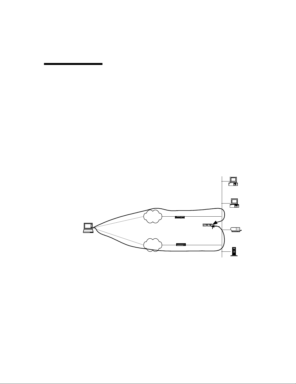
This scenario s ho ws the following:
• One-armed configuration uses only one of the VPN device’s
two interfaces.
• Firewall is not enabled.
• The VPN device (VPND) acts as a VPN server.
Internal
Network
Desktop
System
Internet
Connection
VPN Client
Direct
Dial
Figure: One-Armed Configuration With No Firewall
Figure: One-Armed Configuration With No Firewall
Figure: One-Armed Configuration With No FirewallFigure: One-Armed Configuration With No Firewall
Configuring a One- Ar m ed R outer Conf i g urat i on
Configuring a One- Ar m ed R outer Conf i g urat i on
Configuring a One- Ar m ed R outer Conf i g urat i on Configuring a One- Ar m ed R outer Conf i g urat i on
Internet
PSTN
Router
Router or Remote
Access Server
Router Mode
VPND
No Firewall
Functions
E0
Desktop
System
Laser Printer
When setting up a VPN device, you must configure many global
configuration set tings. You configure the VPN device through
the HP SA3000 Series VPN Manager or command shell.
2 Hewlett-Packard VPN Server Appliance SA3110/SA3150/SA3400/SA3450 Network Layout Reference Guide
Page 8

Client Scen ar io s
To set up a one-armed router configuration, use the
configuration parameters in the following table. Note that the
values of these parameters are examples only; you must enter
values specific to your network.
ne-Armed Rout er Con figu rati on Paramet ers
Table:
Tabl e : O
Table:Table:
NAT by Router
NAT by Router No NAT
NAT by RouterNAT by Router
ne-Armed Rout er Con figu rati on Paramet ers
O
ne-Armed Rout er Con figu rati on Paramet ersne-Armed Rout er Con figu rati on Paramet ers
O O
No NAT
No NATNo NAT
Interface E0:
IP: 10.250.128.2 255.255.255.0
Mode: Red
Interface E1: (not used for
one-armed)
IP: NA
Mode: NA
Configuration file entries/
routing info:
security profile remote user
remote tunnel johndoe
security-profile remote
user
client-ip 10.250.128.2
255.255.255.255
HP SA3000 Series VPN Client
IP: 10.250.128.3
Subnet: 10.250.128.0 (net-
include)
ISP IP: 209.29.128.50 ISP IP: 209.29.128.50
Interface E0:
IP: 205.25.128.2 255.255.255.0
Mode: Red
Interface E1: (not used for onearmed)
IP: NA
Mode: NA
Configuration file entries/routing
info:
security profile remote user
remote tunnel johndoe
security-profile remote user
ip route 209.29.128.50
255.255.255.255 john doe
VPN Client IP: Uses ISP IP (no
client IP)
Subnet: 205.25.128.0 (net-include)
Inline Router
Inline Router
Inline Router Inline Router
Configuration
Configuration
ConfigurationConfiguration
Hewlett-Packard VPN Server Appliance SA3110/SA3150/SA3400/SA3450 Network Layout Reference Guide
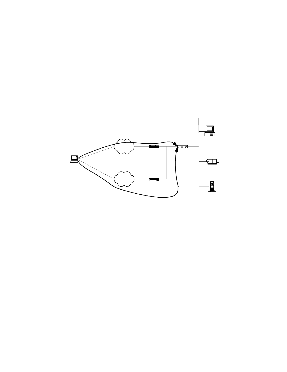
In this scenario, VP N C lient traffic is handled either through a
router (inline) or by directly dialing into the public-switched
telephone network (PSTN).
• For inlin e router configurations:
— The router accepts all incoming client traffic then trans-
fers the traffic to the VPN device.
3
Page 9
HP VPN Server Appliance SA3110/SA3150/SA3400/SA3450 Network Layout Reference Guide
— The VPN device then transfers the traffic on to the local
network to which it is attached. The VPN device may or
may not perform firewall functions on the traffic.
• For direct dial into the PSTN:
— T raffic may go throu gh a router or remote access serve r,
which may or may not perform NAT.
— The traffic then goes through the VPN device, which
may or may not perform firewall functions on the
traffic.
Internal
Network
Internet Connection
VPN Client
Direct Dial
Configuring an Inl ine Rou ter Conf igura tion
Configuring an Inl ine Rou ter Conf igura tion
Configuring an Inl ine Rou ter Conf igura tion Configuring an Inl ine Router Co nfig urati on
When setting up a VPN device, you must configure many global
configuration set tings. You configure the VPN device through
the VPN Manager or command shell.
To set up an inline router configuration, use the configuration
parameters in the following table. Note that the values of these
parameters a re examp les only ; you must enter values s pecific to
your netw or k.
Router Mode
Internet
Router
PSTN
Figure: Inline Router Configuration
Figure: Inline Router Configuration
Figure: Inline Router ConfigurationFigure: Inline Router Configuration
Router or
Remote Access Server
May/May Not NAT
E1
VPND
With/Without
Firewall
Functions
Desktop
System
E0
Laser Printer
File Server
4 Hewlett-Packard VPN Server Appliance SA3110/SA3150/SA3400/SA3450 Network Layout Reference Guide
Page 10

Inline Route r Confi gurati on Para mete rs
Table:
Table:
Table:Table:
NAT by Router
NAT by Router No NAT
NAT by RouterNAT by Router
Inline Route r Confi gurati on Para mete rs
Inline Route r Confi gurati on Para mete rsInline Route r Confi gurati on Para mete rs
No NAT
No NATNo NAT
Client Scen ar io s
Interface E0:
IP: 10.250.128.2 255.255.255.0
Mode: Red
Interface E1:
IP: 192.168.10.2 255.255.255.0
Mode: Red
Configuration file entries/
routing info:
security profile remote user
remote tunnel johndoe
security-profile remote
user
client-ip 10.250.128.3
255.255.255.255
VPN Client IP: 10.250.128.3 VPN Client IP: Uses ISP IP (no
Subnet: 10.250.128.0 (netinclude)
ISP IP: 209.29.128.50 ISP IP: 209.29.128.50
Interface E0:
IP: 205.25.128.2 255.255.255.0
Mode: Red
Interface E1:
IP: 210.35.129.2 255.255.255.0
Mode: Red
Configuration file entries/routing
info:
security profile remote user
remote tunnel johndoe
security-profile remote user
ip route 209.29.128.50
255.255.255.255 john doe
client IP)
Subnet: 205.25.128.0 (net-include)
In Parallel With
In Parallel With
In Parallel With In Parallel With
Firewall
Firewall
Firewall Firewall
(Extranet or
(Extranet or
(Extranet or (Extranet or
Intranet)
Intranet)
Intranet)Intranet)
Hewlett-Packard VPN Server Appliance SA3110/SA3150/SA3400/SA3450 Network Layout Reference Guide
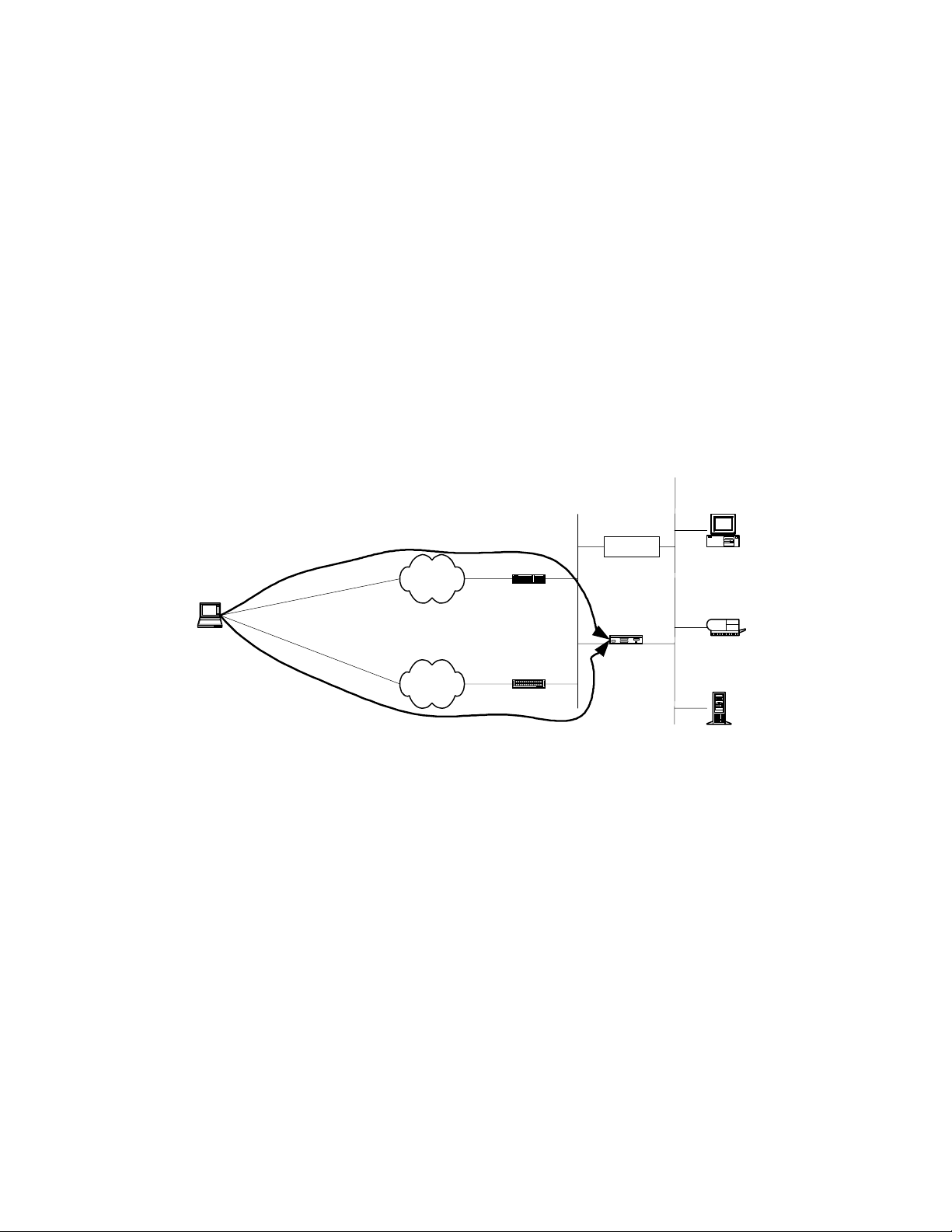
In this scenario, VP N C lient traffic is handled either through a
router (inline) or by directly dialing in to the PSTN. In addition,
there is a third-party firewall on the network handling firewall
functionality.
• For inlin e router configurations:
— The router accepts all incoming client traffic, then trans-
fers the traffic to the VPN device.
— The VPN device then transfers the traffic to the local
network to which it is attached.
— The VPN device is in router mode and does not perform
firewall functi on s.
5
Page 11
HP VPN Server Appliance SA3110/SA3150/SA3400/SA3450 Network Layout Reference Guide
— Traffic is then handed to the third-party firewall, which
performs firewall functions before handing the traffic
onto the local network .
• For direct dial into the PSTN:
— T raffic may go throu gh a router or remote access serve r,
which may or may not perform NAT.
— The traffic then goes through the VPN device (VPND),
which passes the traffic to the local network.
— The third-party firewall then performs firewall functions
on the traffic before passing it to the local network.
Internet
Connection
VPN Client
Internal
Network B
(directly
connected
to Internet)
Internet
Router
Router
PSTN
Direct Dial
Configuring an In Parallel With Firewall Configuration
Configuring an In Parallel With Firewall Configuration
Configuring an In Parallel With Firewall Configuration Configuring an In Parallel With Firewall Configuration
Remote Access Server
Figure: In Parallel With Firewall
Figure: In Parallel With Firewall
Figure: In Parallel With FirewallFigure: In Parallel With Firewall
May/May Not NAT
E1 E0
VPND
Network A
Firewall
Router
Mode
Internal
Desktop System
Laser Printer
File Server
When setting up a VPN device, you must configure many global
configuration set tings. You configure the VPN device through
the VPN Manager or command shell.
To set up an in parallel with firewall configuration, use the
configuration parameters in the following table. Note that the
values of these parameters are examples only; you must enter
values specific to your network.
6 Hewlett-Packard VPN Server Appliance SA3110/SA3150/SA3400/SA3450 Network Layout Reference Guide
Page 12

Client Scen ar io s
Table:
Table: In Parallel With Firewall Configuration Parameters
Table:Table:
VPN Device (NAT by Router)
VPN Device (NAT by Router) VPN Device (No NAT)
VPN Device (NAT by Router)VPN Device (NAT by Router)
In Parallel With Firewall Configuration Parameters
In Parallel With Firewall Configuration Parameters In Parallel With Firewall Configuration Parameters
VPN Device (No NAT)
VPN Device (No NAT)VPN Device (No NAT)
Interface E0:
IP: 10.250.128.2 255.255.255.0
Mode: Red
Interface E1:
IP: 192.168.10.2 255.255.255.0
Mode: Red
Configuration file entries/
routing info:
security profile remote user
remote tunnel johndoe
security-profile remote
user
client-ip 10.250.128.3
255.255.255.255
VPN Client IP: 10.250.128.3 VPN Client IP: Uses ISP IP (no
Subnet: 10.250.128.0 (netinclude)
ISP IP: 209.29.128.50 ISP IP: 209.29.128.50
Interface E0:
IP: 205.25.128.2 255.255.255.0
Mode: Red
Interface E1:
IP: 210.35.129.2 255.255.255.0
Mode: Red
Configuration file entries/routing
info:
security profile remote user
remote tunnel johndoe
security-profile remote user
ip route 209.29.128.50
255.255.255.255 johndoe
client IP)
Subnet: 205.25.128.0 (net-include)
Bridge
Bridge
Bridge Bridge
Configuration
Configuration
ConfigurationConfiguration
Hewlett-Packard VPN Server Appliance SA3110/SA3150/SA3400/SA3450 Network Layout Reference Guide
In this scenario, VP N C lient traffic is handled either through a
router/bridge or by directly dialing into the PSTN.
• For router/bridge configurations:
— The router/br idge acce pts all incoming client traf fic t hen
transfers the traffic to the VPN device.
— The VPN device is set to bridge mode and transfers the
traffic to the local network to which it is attached.
— The VPN device may or may not perform firewall
functions on the traffic.
— The bridge is installed on the internal side of the net-
work with minimal changes to the network topology.
7
Page 13

HP VPN Server Appliance SA3110/SA3150/SA3400/SA3450 Network Layout Reference Guide
• For direct dial into the PSTN:
— T raffic may go throu gh a router or remote access serve r,
which may or may not perform network address translation.
— The traffic then goes through the VPN device, which is
set to bridge mode. The VPN device may or may not
perform firewall functions on the traffic.
Internal
Network A
Internal
Internet Connection
Internet
Network B
(directly
connected
to Internet)
Router
Desktop System
Bridge
Mode
E1 E0
VPND
With/Without
Firewall Functions
Desktop System
Desktop System
Laser Printer
VPN Client
Direct Dial
PSTN
Configuring a Bridge Configuration
Configuring a Bridge Configuration
Configuring a Bridge ConfigurationConfiguring a Bridge Configuration
Router or
Remote Access Server
Desktop System
Figure: Bridge Configuration
Figure: Bridge Configuration
Figure: Bridge ConfigurationFigure: Bridge Configuration
File Server
When setting up a VPN device, you must configure many global
configuration You configure the VPN device through the VPN
Manager or command shell.
To set up a bridge configuration, use the configuration
parameters in the foll ow ing table. Note that the values of these
parameters ar e examples only; you must enter value s specific t o
your netw or k.
8 Hewlett-Packard VPN Server Appliance SA3110/SA3150/SA3400/SA3450 Network Layout Reference Guide
Page 14

Table:
Table: Bridge Configuration Parameters
Table:Table:
NAT by Router
NAT by Router Inline No NAT
NAT by RouterNAT by Router
Bridge Configuration Parameters
Bridge Configuration Parameters Bridge Configuration Parameters
Inline No NAT
Inline No NATInline No NAT
Client Scen ar io s
Interface E0:
Mode: Red
Interface E1:
Mode: Red
Bridge IP: 10.250.128.2 Bridge IP: 205.25.128.2
Configuration file entries/routing
info:
security profile remote user
remote tunnel johndoe
security-profile remote user
VPN Client IP: 10.250.128.3 VPN Client IP: Uses ISP IP (no
Subnet: 10.250 .128.0 (net-incl ud e) Subnet: 205.25.128.0
ISP IP: 209.29.128.50 ISP IP: 209.29.128.50
Edge Router
Edge Router
Edge Router Edge Router
Configuration
Configuration
ConfigurationConfiguration
Interface E0:
Mode: Red
Interface E1:
Mode: Red
255.255.255.0
Configuration file entries/routing
info:
security profile remote user
remote tunnel johndoe
security-profile remote user
client IP)
In this scenario, the VPN device acts as an “edge” router; it is the
only device between the Internet and the local network.
• The VPN Client makes a s ecure VPN connection through the
Internet to the VPN device.
• The VPN device is conf igured to router mode.
• The VPN device may or may not perform firewall functions
on the traffic.
• The VPN Client has no means to perform d irect dial to the
local network; it must go through a VPN tunnel.
Hewlett-Packard VPN Server Appliance SA3110/SA3150/SA3400/SA3450 Network Layout Reference Guide
9
Page 15

HP VPN Server Appliance SA3110/SA3150/SA3400/SA3450 Network Layout Reference Guide
Internal
Network
Internet
Connection
VPN Client
Router Mode
E1
Internet
With/Without Firewall
Router or Remote
Access Server
No Direct
Figure: Edge Router Configuration
Figure: Edge Router Configuration
Figure: Edge Router ConfigurationFigure: Edge Router Configuration
Configuring a n Edge Ro uter Conf igurat ion
Configuring a n Edge Ro uter Conf igurat ion
Configuring a n Edge Ro uter Conf igurat ion Configuring a n Edge Ro uter Conf igurat ion
E0
VPND
Functions
Dial
Desktop System
Laser Printer
File Server
When setting up a VPN device, you must configure many global
configuration set tings. You configure the VPN device through
the VPN Manager or command shell.
To set up an edge router configuration, use the configuration
parameters in the following table. Note that the values of these
parameters ar e examples only; you must enter value s specific t o
your netw or k.
Table:
Table: Edge Router Configuration Parameters
Table:Table:
VPN Device (NAT by Router)
VPN Device (NAT by Router) VPN Device (No NAT)
VPN Device (NAT by Router)VPN Device (NAT by Router)
Interface E0:
IP: 10.250.128.2 255.255.255.0
Mode: Red
Interface E1:
IP: 210.35.129.2 255.2 55.255.0
Mode: Black
10 Hewlett-Packard VPN Server Appli ance SA3110/SA3150/SA3400/SA3450 Network Layout Reference Guide
Edge Router Configuration Parameters
Edge Router Configuration Parameters Edge Router Configuration Parameters
VPN Device (No NAT)
VPN Device (No NAT)VPN Device (No NAT)
Interface E0:
IP: 205.25.128.2 255.255.255.0
Mode: Red
Interface E1:
IP: 210.35.129.2 255.255.255.0
Mode: Red
Page 16

VPN Device (NAT by Router)
VPN Device (NAT by Router) VPN Device (No NAT)
VPN Device (NAT by Router)VPN Device (NAT by Router)
VPN Device (No NAT)
VPN Device (No NAT)VPN Device (No NAT)
Client Scen ar io s
Behind a
Behind a
Behind a Behind a
Firewall With or
Firewall With or
Firewall With or Firewall With or
Without NAT
Without NAT
Without NAT Without NAT
(One-Armed)
(One-Armed)
(One-Armed)(O ne-Arme d)
Configuration file entries/
routing info:
security profile remote user
remote tunnel johndoe
security-profile remote
user
client-ip 10.250.128.3
255.255.255.255
VPN Client IP: 10.250.128.3 VPN Client IP: Uses ISP IP (no
Subnet: 10.250.128.0 (netinclude)
ISP IP: 209.29.128.50 ISP IP: 209.29.128.50
In this scenario, VP N C lient traffic is handled either through a
router (inline) or by directly dialing in to the PSTN. The traffic
passes throu gh a thi rd- par ty fire wal l before pass in g throu gh th e
VPN device.
• For inlin e router configurations:
— The router accepts all incoming client traffic, then trans-
fers the traffic to the third-party firewall.
— The third-party firewall performs firewall functionality
on the traffic before passing it to the VPN device.
— The VPN device takes the encrypted traffic and decrypts
it befor e passing it to the local n e twork.
• For direct dial into the PSTN:
— Traffic may go through a router or remote access server,
which may or may not perform NAT.
— The traffic then goes through a third-party firewall. The
third- party firewall performs firewall functionality on
the traffic before passing it to the VPN device.
— The VPN device then decrypts the encrypted VPN traffic
and passes it to the loca l network .
Configuration file entries/routing
info:
security profile remote user
remote tunnel johndoe
security-profile remote user
ip route 209.29.128.50
255.255.255.255 johndoe
client IP)
Subnet: 205.25.128.0 (net-include)
Hewlett-Packard VPN Server Appliance SA3110/SA3150/SA3400/SA3450 Network Layout Reference Guide
11
Page 17

HP VPN Server Appliance SA3110/SA3150/SA3400/SA3450 Network Layout Reference Guide
Internet Connection
VPN Client
Direct Dial
Configuring a Behind a Firewall (One-Armed)
Configuring a Behind a Firewall (One-Armed)
Configuring a Behind a Firewall (One-Armed)Configuring a Behind a Firewall (One-Armed)
Network Layout
Network Layout
Network Layout Network Layout
When setting up a VPN device, you must configure many global
configuration set tings. You configure the VPN device through
the VPN Manager or command shell.
Internal Network A
Internal Network B
(directly connected
to Internet)
May/May Not NAT
Internet
Router
May/May Not NAT
PSTN
Router or Remote
Access Server
Figure: Behind a Firewall (One-Armed)
Figure: Behind a Firewall (One-Armed)
Figure: Behind a Firewall (One-Armed)Figure: Behind a Firewall (One-Armed)
Router Mode
VPND
Desktop System
Desktop System
Firewall
E0
Laser Printer
File Server
To set up a behind a firewall (one-armed ) configurat ion, use th e
configuration parameters in the following table. Note that the
values of these parameters are examples only; you must enter
values specific to your network.
Table:
Table: Behind a Firewall (One-Armed) Configuration
Table:Table:
VPN Device
VPN Device
VPN Device VPN Device
(NAT by Router)
(NAT by Router)
(NAT by Router)(NAT by Router)
Interface E0:
IP: 10.250.128.2 255.255.255.0
Mode: Red
12 Hewlett-Packard VPN Server Appli ance SA3110/SA3150/SA3400/SA3450 Network Layout Reference Guide
Behind a Firewall (One-Armed) Configuration
Behind a Firewall (One-Armed) Configuration Behind a Firewall (One-Armed) Configuration
Parameters
Parameters
ParametersParameters
VPN Device (No NAT)
VPN Device (No NAT)
VPN Device (No NAT)VPN Device (No NAT)
Interface E0:
IP: 205.25.128.2 255.255.255.0
Mode: Red
Page 18

VPN Device
VPN Device
VPN Device VPN Device
(NAT by Router)
(NAT by Router)
(NAT by Router)(NAT by Router)
VPN Device (No NAT)
VPN Device (No NAT)
VPN Device (No NAT)VPN Device (No NAT)
Client Scen ar io s
Behind a
Behind a
Behind a Behind a
Firewall With or
Firewall With or
Firewall With or Firewall With or
Without NAT
Without NAT
Without NAT Without NAT
(Inline)
(Inline)
(Inline)(Inline)
Interface E1: (Not used for
one-armed)
IP: NA
Mode: NA
Configuration file entries/
routing info:
security profile remote user
remote tunnel johndoe
security-profile remote
user
client-ip 10.250.128.3
255.255.255.255
VPN Client IP: 10.250.128.3 VPN Client IP: Uses ISP IP (no
Subnet: 10.250.128.0 (netinclude)
ISP IP: 209.29.128.50 ISP IP: 209.29.128.50
In this scenario, VP N C lient traffic is handled either through a
router (inline) or by directly dialing in to the PSTN. The traffic
passes through a th ird -p ar ty fir e wal l th at m ay or may not
perform NAT before passing the traffic to the VPN device.
• For inlin e router configurations:
— The router accepts all incoming client traffic, then trans-
fers the traffic to the third-party firewall.
— The third-party firewall may or may not perform NAT
before passing the traffic to the VPN device.
— The VPN device then decrypts the encrypted VPN traffic
and passes it to the loca l network .
• For direct dial into the PSTN:
— Traffic may go through a router or remote access server,
which may or may not perform NAT.
Interface E1: (Not used for onearmed)
IP: NA
Mode: NA
Configuration file entries/routing
info:
security profile remote user
remote tunnel johndoe
security-profile remote user
ip route 209.29.128.50
255.255.255.255 johndoe
client IP)
Subnet: 205.25.128.0 (net-include)
Hewlett-Packard VPN Server Appliance SA3110/SA3150/SA3400/SA3450 Network Layout Reference Guide
13
Page 19

HP VPN Server Appliance SA3110/SA3150/SA3400/SA3450 Network Layout Reference Guide
— The traffic then goes through the third-party firewall,
which also may or may not perform NAT before being
handed to the VPN device.
— The VPN device then decrypts the encrypted VPN traffic
and passes it to the local network.
Internet Connection
VPN Client
May/May Not
Internet
PSTN
Direct Dial
Figure: Behind a Firewall (Inline)
Figure: Behind a Firewall (Inline)
Figure: Behind a Firewall (Inline)Figure: Behind a Firewall (Inline)
Configuring a Behind a Firewall (Inline)
Configuring a Behind a Firewall (Inline)
Configuring a Behind a Firewall (Inline)Configuring a Behind a Firewall (Inline)
Network Layout
Network Layout
Network Layout Network Layout
Router
May/May Not NAT
Router or Remote
Access Server
NAT
Firewall
VPND
Router Mode
E1
VPNG
E0
Laser Printer
File Server
When setting up a VPN device, you must configure many global
configuration set tings. You configure the VPN device through
the VPN Manager or command shell.
To set up a behind a firewall (inline) configuration, use the
configuration parameters in the following table. Note that the
values of these parameters are examples only; you must enter
values specific to your network.
Desktop
System
14 Hewlett-Packard VPN Server Appli ance SA3110/SA3150/SA3400/SA3450 Network Layout Reference Guide
Page 20

Client Scen ar io s
Table:
Table: Behind a Firewall (Inline) Configuration Parameters
Table:Table:
VPN Device (NAT by Router)
VPN Device (NAT by Router) VPN Device (No NAT)
VPN Device (NAT by Router)VPN Device (NAT by Router)
Behind a Firewall (Inline) Configuration Parameters
Behind a Firewall (Inline) Configuration Parameters Behind a Firewall ( Inline) Conf iguratio n Para mete rs
VPN Device (No NAT)
VPN Device (No NAT)VPN Device (No NAT)
Interface E0:
IP: 10.250.128.2 255.255.255.0
Mode: Red
Interface E1:
IP: 192.168.10.2 255.255.255.0
Mode: Red
Configuration file entries/
routing info:
security profile remote user
remote tunnel johndoe
security-profile remote
user
client-ip 10.250.128.3
255.255.255.255
VPN Client IP: 10.250.128.3 VPN Client IP: Uses ISP IP (no
Subnet: 10.250.128.0 (netinclude)
ISP IP: 209.29.128.50 ISP IP: 209.29.128.50
Interface E0:
IP: 205.25.128.2 255.255.255.0
Mode: Red
Interface E1:
IP: 210.35.129.2 255.2 55.255.0
Mode: Red
Configuration file entries/routing
info:
security profile remote user
remote tunnel johndoe
security-profile remote user
ip route 209.29.128.50
255.255.255.255 johndoe
client IP)
Subnet: 205.25.128.0 (net-include)
The VPN Device
The VPN Device
The VPN Device The VPN Device
as a Firewall
as a Firewall
as a Firewallas a Firewall
Hewlett-Packard VPN Server Appliance SA3110/SA3150/SA3400/SA3450 Network Layout Reference Guide
In this scenario, VP N C lient traffic is handled either through a
router (inline) or by directly dialing in to the PSTN. The traffic
passes through firewall functionality on the VPN device. The
VPN device may or may not perform NAT before passing the
traffic to the local network.
• For inlin e router configurations:
— The router accepts all incoming client traffic, then trans-
fers the traffic to the VPN device.
— The third-party firewall may or may not perform NAT
before passing the traffic to the VPN device.
15
Page 21

HP VPN Server Appliance SA3110/SA3150/SA3400/SA3450 Network Layout Reference Guide
— The VPN device then performs firewall functionality on
the traffic and passes it to the local network.
— The VPN device may or may not perform NAT.
• For direct dial into the PSTN:
— T raffic may go through a router or remote access server .
— The traffic then goes through fi rewa l l func ti on a lity on
the VPN device.
— The VPN device may or may not perform NAT before
being handed onto the local network.
Internal
Network A
Internet Connection
VPN Client
Direct Dial
Internal
Network B
(directly
connected to
Internet)
Internet
Router
Router or Remote
Access Server
PSTN
Figure: VPN Device as a Firewa ll
Figure: VPN Device as a Firewa ll
Figure: VPN Device as a Firewa llFigure: VPN Device as a Firewa ll
Configuring a VPN Device as a Firewall
Configuring a VPN Device as a Firewall
Configuring a VPN Device as a FirewallConfiguring a VPN Device as a Firewall
E1 E0
VPND
With Firewall
Functions
Router Mode
May/May Not NAT
Desktop System
Desktop System
Laser Printer
File Server
When setting up a VPN device, you must configure many global
configuration set tings. You configure the VPN device through
the VPN Manager or command shell.
To set up a VPN device as a firewall configuration, use the
configuration parameters in the following table. Note that the
16 Hewlett-Packard VPN Server Appli ance SA3110/SA3150/SA3400/SA3450 Network Layout Reference Guide
Page 22

Client Scen ar io s
values of these parameters are examples only; you must enter
values specific to your network.
Table:
Table: VPN Device as a Firewall Configuration Parameters
Table:Table:
VPN Device (NAT by Router)
VPN Device (NAT by Router) VPN Device (No NAT)
VPN Device (NAT by Router)VPN Device (NAT by Router)
VPN Device as a Firewall Configuration Parameters
VPN Device as a Firewall Configuration Parameters VPN Device as a Firewall Configuration Parameters
VPN Device (No NAT)
VPN Device (No NAT)VPN Device (No NAT)
Interface E0:
IP: 10.250.128.2 255.255.255.0
Mode: Red
Interface E1:
IP: 192.168.10.2 255.255.255.0
Mode: Black
Configuration file entries/
routing info:
security-profile remote user
remote tunnel johndoe
security-profile remote
user
client-ip 10.250.128.3
Interface E0:
IP: 205.25.128.2 255.255.255.0
Mode: Red
Interface E1:
IP: 210.35.129.2 255.2 55.255.0
Mode: Black
Configuration file entries/routing
info:
security-profile remote user
remote tunnel johndoe
security-profile remote user
ip route 209.29.128.50
255.255.255.255 johndoe
255.255.255.255
VPN Client IP: 10.250.128.3 VPN Client IP: Uses ISP IP (no
client IP)
Subnet: 10.250.128.0 (net-
Subnet: 205.25.128.0 (net-include)
include)
ISP IP: 209.29.128.50 ISP IP: 209.29.128.50
Hewlett-Packard VPN Server Appliance SA3110/SA3150/SA3400/SA3450 Network Layout Reference Guide
17
Page 23

HP VPN Server Appliance SA3110/SA3150/SA3400/SA3450 Network Layout Reference Guide
LAN-to-LAN Scenarios
LAN-to-LAN Scenarios
LAN-to-LAN ScenariosLAN-to-LAN Scenarios
In Parallel With
In Parallel With
In Parallel With In Parallel With
a Firewall
a Firewall
a Firewall a Firewall
(Without NAT)
(Without NAT)
(Without NAT)(Without NAT)
This scenario s ho ws the following:
• A LAN-to-LAN connection between two VPN devices with no
NAT.
• Each VPN device is attached to a router. The routers
connect through the Internet.
• Traffic travels from one local network, through the LAN-toLAN connection, to the other local network.
• Traffic passes through the VPN device, which is in router
mode.
• The VPN device passes the VPN traff ic on to the local
network.
Note:
Note: You must add a route to the third-party firewall for the
Note: Note:
network behind VPN device B.
Firewall
File Server
Desktop System
Laser Printer
18 Hewlett-Packard VPN Server Appli ance SA3110/SA3150/SA3400/SA3450 Network Layout Reference Guide
E0 E1
VPND
Router Mode
Router/
Default Device
Figure: In Parallel With a Firewall (No NAT)
Figure: In Parallel With a Firewall (No NAT)
Figure: In Parallel With a Firewall (No NAT)Figure: In Parallel With a Firewall (No NAT)
Internet
Router/
Default GW
Internal
Network
(directly
connected to
Internet)
E1 E0
VPND
Router Mode
Desktop System
Laser Printer
File Server
Page 24

LAN-to-LAN Scenarios
Configurin g an In Paral lel Wi th a Firewal l (No NAT) Ne twork
Configurin g an In Paral lel Wi th a Firewal l (No NAT) Ne twork
Configurin g an In Paral lel Wi th a Firewal l (No NAT) Ne twork Configurin g an In Paral lel Wi th a Firewal l (No NAT) Ne twork
Layout
Layout
LayoutLayout
When setting up a VPN device, you must configure many global
configuration settings. You configure the VPN device through
the VPN Manager or command shell.
To set up a parallel with a firewall (no NAT) configuration, use
the configuration parameters in the following table. Note that the
values of these parameters are examples only; you must enter
values specific to your network.
Table:
Table: In Parallel With a Firewall (No NAT) Configuration
Table:Table:
VPN Device A (No NAT)
VPN Device A (No NAT) VPN Device B (No NAT)
VPN Device A (No NAT)VPN Device A (No NAT)
In Parallel With a Firewall (No NAT) Configuration
In Parallel With a Firewall (No NAT) Configuration In Parallel With a Firewall (No NAT) Configuration
Parameters
Parameters
ParametersParameters
VPN Device B (No NAT)
VPN Device B (No NAT)VPN Device B (No NAT)
Interface E0:
IP: 10.250.128.2 255.255.255.0
Mode: Red
Interface E1:
IP: 2 09.80.1 0.1 255.255.255.0
Default device: 209.80.10.2
Mode: Red
Config file entries/routing info:
security-profile site-to-site
tunnel SanFrancisco
route 10.250.130.0
255.255.255.0
device 209.80.20.1
In Parallel With
In Parallel With
In Parallel With In Parallel With
a Firewall (With
a Firewall (With
a Firewall (With a Firewall (With
NAT)
NAT)
NAT)NAT)
Interface E0:
IP: 10.250.130.2 255.255.255.0
Mode: Red
Interface E1:IP: 209.80.20.1
255.255.255.0
Mode: Red
Config file entries/routing info:
security-profile site-to-site
tunnel Boston
route 10.250.128.0 255.255.255.0
device 209.80.10.1
This scenario s ho ws the following:
• A LAN-to-LAN connection between two VPN devices using
NAT.
• Each VPN device is attached to a router. The routers
connect through the Internet and perform NAT.
• Traffic travels from one local network, through the LAN-toLAN connection, to the other local network.
Hewlett-Packard VPN Server Appliance SA3110/SA3150/SA3400/SA3450 Network Layout Reference Guide
19
Page 25

HP VPN Server Appliance SA3110/SA3150/SA3400/SA3450 Network Layout Reference Guide
• Traffic passes through the VPN device, which is in router
mode.
• The VPN device passes the VPN traff ic to the third-party
firewall (in parallel with the VPN device).
• The third-party firewall performs firewall functionality on
the traffic, then passes the traffic to the local network.
Firewall
Desktop SystemDesktop System
File Server
Desktop System
Laser Printer
E0 E1
VPND A Router
Router Mode
Firewall A
Configuring an In Parallel With a Firewall (With NAT) Network
Configuring an In Parallel With a Firewall (With NAT) Network
Configuring an In Parallel With a Firewall (With NAT) Network Configuring an In Parallel With a Firewall (With NAT) Network
Layout
Layout
Layout Layout
When setting up a VPN device, you must configure many global
configuration set tings. You configure the VPN device through
the VPN Manager or command shell.
To set up an in parallel with a firewall (with NAT) co nfiguratio n,
use the configuration parameters in the following table. Note
that the values of these parameters are examples only ; you must
enter values specific to your network.
Desktop System
Internet
Figure: In Parallel With a Firewall (With NAT)
Figure: In Parallel With a Firewall (With NAT)
Figure: In Parallel With a Firewall (With NAT)Figure: In Parallel With a Firewall (With NAT)
Router
Firewall B
E1 E0
VPND B
Router Mode
Laser Printer
File Server
20 Hewlett-Packard VPN Server Appli ance SA3110/SA3150/SA3400/SA3450 Network Layout Reference Guide
Page 26

LAN-to-LAN Scenarios
Table:
Table: In Parallel With a Firewall (With NAT) Configuration
Table:Table:
VPN Device A (NAT by
VPN Device A (NAT by
VPN Device A (NAT by VPN Device A (NAT by
Router)
Router)
Router)Router)
In Parallel With a Firewall (With NAT ) Con figuration
In Parallel With a Firewall (With NAT ) Con figuration In Parallel With a Firewall (With NAT ) Con figuration
Parameters
Parameters
ParametersParameters
VPN Device B (NAT by Router)
VPN Device B (NAT by Router)
VPN Device B (NAT by Router)VPN Device B (NAT by Router)
Behind a
Behind a
Behind a Behind a
Firewall (One-
Firewall (One-
Firewall (One-Firewall (OneArmed) With or
Armed) With or
Armed) With or Armed) With or
Without NAT
Without NAT
Without NAT Without NAT
Interface E0:
IP: 10.250.128.2 255.255.255.0
Mode: Red
Interface E1:
IP: 192.168.10.2 255.255.255.0
Default device: 192.168.10.4
Mode: Red
Configuration file entries/
routing info:
security-profile site-to-site
tunnel Boston
route 209.29.128.50
255.255.255.0
This scenario s ho ws the following:
• A LAN-to-LAN connection between two VPN devices.
• VPN device A is attached to Router A. Router B is attached
to the local network. The routers connect through the
Internet.
• Traffic travels from one local network, through the LAN-toLAN connection, to the other local network.
• Router B passes the traffic first to the thi rd-party firewall,
which resides in parallel to the VPN device.
• The third-party firewall may or may not perform network
address translation.
• The third-party firewall performs firewall functionality on
the traffic, then passes the traffic to the VPN device.
• The VPN device decrypts the encrypte d VPN traffic and
passes it to the local network.
Interface E0:
IP: 10.250.130.2 255.255.255.0
Mode: Red
Interface E1:
IP: 192.168.12.2 255.2 55.255.0
Default device: 192.168.12.4
Mode: Red
Configuration file entries/routing
info:
security-profile site-to-site
tunnel SanFrancisco
route 209.29.128.50 255.255.255.0
Note:
Note: You must add a route to the firewall for the network that
Note: Note:
Hewlett-Packard VPN Server Appliance SA3110/SA3150/SA3400/SA3450 Network Layout Reference Guide
21
Page 27

HP VPN Server Appliance SA3110/SA3150/SA3400/SA3450 Network Layout Reference Guide
is in front of VPN device B (which routes to the VPN device B
interface for the subnet access ible through the tunnel). If you do
not add this route, local machines (w it h their def aul t de vice
pointing to the firewall) will not be able to route to the VPN
device A network.
File Server
Desktop System
Laser Printer
May/May Not
NAT
Firewall
E0 E1 E0
VPND A Router Router VPND B
Router Mode
Configuring a Behind a Firewall (One-Armed) With NAT Network
Configuring a Behind a Firewall (One-Armed) With NAT Network
Configuring a Behind a Firewall (One-Armed) With NAT Network Configuring a Behind a Firewall (One-Armed) With NAT Network
Layout
Layout
Layout Layout
Internet
Router Mode
Figure: Behind a Firewall (One-Armed)
Figure: Behind a Firewall (One-Armed)
Figure: Behind a Firewall (One-Armed)Figure: Behind a Firewall (One-Armed)
When setting up a VPN device, you must configure many global
configuration set tings. You configure the VPN device through
the VPN Manager or command shell.
Desktop SystemDesktop System
Desktop System
Laser Printer
File Server
To set up a behind a firewall (one-armed) with NAT
configuration , use the configuratio n parameters in the follo wing
table. Note that the values of these parameters are examples
only; you must enter values specific to your network.
22 Hewlett-Packard VPN Server Appli ance SA3110/SA3150/SA3400/SA3450 Network Layout Reference Guide
Page 28

Table:
Table: Behind a F ir ewall (O ne-Armed) With NAT
Table:Table:
VPN Device A (NAT by
VPN Device A (NAT by
VPN Device A (NAT by VPN Device A (NAT by
Router)
Router)
Router)Router)
Behind a Fir ewall (O ne-Armed) With N AT
Behind a Fir ewall (O ne-Armed) With N AT Behind a Fir ewall (O ne-Armed) With N AT
Configuration Parameters
Configuration Parameters
Configuration ParametersConfiguration Parameters
VPN Device B (NAT by Router)
VPN Device B (NAT by Router)
VPN Device B (NAT by Router)VPN Device B (NAT by Router)
LAN-to-LAN Scenarios
Interface E0:
IP: 10.250.128.2 255.255.255.0
Mode: Red
Interface E1:
IP: 192.168.10.2 255.255.255.0
Mode: Red
Interface E0:
IP: 10.250.135.2 255.255.255.0
Mode: Red
Interface E1: (Not used for onearmed)
IP: N/A
Mode: N/A
Config file entries/routing
info:
security-profile site-to-site
tunnel SanFrancisco
security-profile site-to-site
route 10.250.135.0
Config file entries/routing info:
security-profile site-to-site
tunnel Boston
security-profile site-to-site
route 209.29.128.50
255.255.255.255
255.255.255.0
Configurin g a Behin d a Firewal l (One -Armed ) Without NAT
Configurin g a Behin d a Firewal l (One -Armed ) Without NAT
Configurin g a Behin d a Firewal l (One -Armed ) Without NAT Configurin g a Behin d a Firewal l (One -Armed ) Without NAT
Network Layout
Network Layout
Network Layout Network Layout
When setting up a VPN device, you must configure many global
configuration settings. You configure the VPN device through
the VPN Manager or command shell.
To set up a behind a firewall (one-armed) without NAT
configuration, u s e the conf igu ration parameter s in t he following
table. Note that the values of these parameters are examples
only; you must enter values specific to your network.
Hewlett-Packard VPN Server Appliance SA3110/SA3150/SA3400/SA3450 Network Layout Reference Guide
23
Page 29

HP VPN Server Appliance SA3110/SA3150/SA3400/SA3450 Network Layout Reference Guide
Table:
Table: Behind a Firewall Without NAT
Table:Table:
VPN Device A (No NAT)
VPN Device A (No NAT) VPN Device B (No NAT)
VPN Device A (No NAT)VPN Device A (No NAT)
Behind a Firewall Without NAT
Behind a Firewall Without NAT Behind a Firewall Without NAT
VPN Device B (No NAT)
VPN Device B (No NAT)VPN Device B (No NAT)
Behind a
Behind a
Behind a Behind a
Firewall That
Firewall That
Firewall That Firewall That
May or May Not
May or May Not
May or May Not May or May Not
Use NA T
Use NA T
Use NA T Use NA T
(Inline)
(Inline)
(Inline)(Inline)
Interface E0:
IP: 205.25.128.2 255.255.255.0
Mode: Red
Interface E1:
IP: 209.80.10.25 255.2 55.255.0
Default device: 209.80.10.2
Mode: Red
Config file entries/routing
info:
security-profile site-to-site
tunnel SanFrancisco
security-profile site-to-site
ip route 205.25.135.0
255.255.255.0 205.25.135.2
This scenario s ho ws the following:
• A LAN-to-LAN connection between two VPN devices.
• VPN device A is directly attached to Router A. Router B is
directly attached to a third-party firewall. The routers
connect through the Internet.
• Traf fic tra vels from Rout er A to Router B. Ro ut er B passes
traffic directly through the third-party firewall.
• The third-party firewall performs firewall functionality on
the traffic and may or may not use NAT.
• The third-party firewall then passes the traffic to the VPN
device B, which is directly attached to it.
• The VPN device B decrypts the VPN traffic before passing it
to the local network.
Interface E0:
IP: 205.25.135.2 255.255.255.0
Mode: Red
Interface E1: (Not used for onearmed)
IP: N /A
Mode: N / A
Config file entries/routing info:
security-profile site-to-site
tunnel Boston
security-profile site-to-site
route 205.25.128.0 255.255.255.0
209.80.10.25
24 Hewlett-Packard VPN Server Appli ance SA3110/SA3150/SA3400/SA3450 Network Layout Reference Guide
Page 30

File Server
Desktop System
Laser Printer
E0 E1
VPND A Router
Router Mode
Figure: Behind a Firewall That May or May Not Use NAT
Figure: Behind a Firewall That May or May Not Use NAT
Figure: Behind a Firewall That May or May Not Use NAT Figure: Behind a Firewall That May or May Not Use NAT
Internet
Router
Internal
Network
(directly
connected
to Internet)
May/May
Not NAT
Firewall
(Inline)
(Inline)
(Inline)(Inline)
E0
E1
VPND B
Router
Mode
LAN-to-LAN Scenarios
Desktop SystemDesktop System
Desktop System
Laser Printer
File Server
Configurin g a Behin d a Firewal l (Inli ne) Netw ork Layou t
Configurin g a Behin d a Firewal l (Inli ne) Netw ork Layou t
Configurin g a Behin d a Firewal l (Inli ne) Netw ork Layou t C onfig urin g a Behind a Firew al l (Inline ) Netw ork Layou t
When setting up a VPN device, you must configure many global
configuration settings. You configure the VPN device through
the VPN Manager or command shell.
To set up a behind a firewall (inline) configuration, use the
configuration parameters in the following tables (with or
without NAT). No te that the values of these parameters are
examples only; you must enter values specific to your network.
Hewlett-Packard VPN Server Appliance SA3110/SA3150/SA3400/SA3450 Network Layout Reference Guide
25
Page 31

HP VPN Server Appliance SA3110/SA3150/SA3400/SA3450 Network Layout Reference Guide
Table:
Table: Behind a Firewall wIth NAT (Inline) Configuration
Table:Table:
VPN Device A (NAT by
VPN Device A (NAT by
VPN Device A (NAT by VPN Device A (NAT by
Router)
Router)
Router)R oute r )
Behind a Firewall wIth NAT (Inline) Configuration
Behind a Firewall wIth NAT (Inline) Configuration Behind a Firewall wIth NAT (Inline) Configuration
Parameters
Parameters
ParametersParameters
VPN Device B (NAT by Router)
VPN Device B (NAT by Router)
VPN Device B (NAT by Router)VPN Device B (NAT by Router)
Interface E0:
IP: 10.250.128.2 255.255.255.0
Mode: Red
Interface E1:
IP: 192.168.10.2 255.2 55.255.0
Mode: Red
Config file entries/routing
info:
security-profile site-to-site
tunnel SanFrancisco
ip route 10.250.135.0
Interface E0:
IP: 10.250.128.2 255.255.255.0
Mode: Red
Interface E1:
IP: 192.168.10.2 255.255.255.0
Mode: Red
Config file entries/routing info:
security-profile site-to-site
tunnel Boston
ip route 10.250.128.0 255.255.255. 0
209.80.10.1
255.255.255.0 205.25.135.1
Subnet: 10.250.128.0 (net-
Subnet: 10.250.128.0 (net-include)
include)
Table:
Table: Behind a Firewall Without NAT (Inline)
Table:Table:
VPN Device A (No NAT)
VPN Device A (No NAT) VPN Device B (No NAT)
VPN Device A (No NAT)VPN Device A (No NAT)
Interface E0:
IP: 205.25.128.2 255.255.255.0
Mode: Red
Behind a Fire wall Without NAT (Inline)
Behind a Fire wall Without NAT (Inline) Behind a Fire wall Without NAT (Inline)
VPN Device B (No NAT)
VPN Device B (No NAT)VPN Device B (No NAT)
Interface E0:
IP: 210.25.135.2 255.255.255.0
Mode: Red
Interface E1:
IP: 205.35.129.2 255.2 55.255.0
Mode: Red
26 Hewlett-Packard VPN Server Appli ance SA3110/SA3150/SA3400/SA3450 Network Layout Reference Guide
Interface E1:
IP: 210.35.129.2 255.255.255.0
Mode: Red
Page 32

LAN-to-LAN Scenarios
VPN Device A (No NAT)
VPN Device A (No NAT) VPN Device B (No NAT)
VPN Device A (No NAT)VPN Device A (No NAT)
VPN Device B (No NAT)
VPN Device B (No NAT)VPN Device B (No NAT)
The VPN Device
The VPN Device
The VPN Device The VPN Device
as a Firewall
as a Firewall
as a Firewall as a Firewall
(With or Without
(With or Without
(With or Without (With or Without
NAT)
NAT)
NAT)NAT)
Config file entries/routing
info:
security-profile site-to-site
tunnel SanFrancisco
ip route 210.25.129.0
255.255.255.0 205.25.128.2
This scenario s ho ws the following:
• A LAN-to-LAN connection between two VPN devices.
• Each VPN device is directly attached to a router. The routers
connect through the Internet.
• Traf fic trave ls from Router A to Router B. Router B passes
traffic directly through the VPN device.
• The VPN device performs f irewall function ality on the traf fic
and may or may not use NAT.
• The VPN device B decrypts the VPN traffic before passing it
to the local network.
Config file entries/routing info:
security-profile site-to-site
tunnel Boston
ip route 205.35.129.0 255.255.255.0
210.25.135.2
Hewlett-Packard VPN Server Appliance SA3110/SA3150/SA3400/SA3450 Network Layout Reference Guide
27
Page 33

HP VPN Server Appliance SA3110/SA3150/SA3400/SA3450 Network Layout Reference Guide
Desktop SystemDesktop System
File Server
Desktop System
Laser Printer
E0 E1
VPND A Router Router VPND B
Router Mode
May/May Not NAT
Configuring the VPN Device as a Firewall
Configuring the VPN Device as a Firewall
Configuring the VPN Device as a FirewallConfiguring the VPN Device as a Firewall
Internet
Figure: VPN Device as a Firewa ll
Figure: VPN Device as a Firewa ll
Figure: VPN Device as a Firewa ll Figure: VPN Device as a Firewa ll
E1 E0
Router Mode
With Firewall Functions Enabled
May/May Not NAT
When setting up a VPN device, you must configure many global
configuration set tings. You configure the VPN device through
the VPN Manager or command shell.
To set up a VPN device as a firewall configuration, use the
configuration parameters in the following tables (with and
without NAT). No te that the values of these parameters are
examples only; you must enter values specific to your network.
Desktop System
Laser Printer
File Server
28 Hewlett-Packard VPN Server Appli ance SA3110/SA3150/SA3400/SA3450 Network Layout Reference Guide
Page 34

LAN-to-LAN Scenarios
Table:
Table: VPN Device as a Firewall With NAT Configuration
Table:Table:
VPN Device A (NAT by
VPN Device A (NAT by
VPN Device A (NAT by VPN Device A (NAT by
Router)
Router)
Router)Router)
VPN Device as a Firewall With NAT Configuration
VPN Device as a Firewall With NAT Configuration VPN Device as a Firewall With NAT Configuration
Parameters
Parameters
ParametersParameters
VPN Device B (NAT by Router)
VPN Device B (NAT by Router)
VPN Device B (NAT by Router)VPN Device B (NAT by Router)
Interface E0:
IP: 10.250.128.2 255.255.255.0
Mode: Red
Interface E1:
IP: 192.168.10.2 255.255.255.0
Mode: Red
Config file entries/routing
info:
security-profile site-to-site
site-to-site tunnel
SanFrancisco
Interface E0:
IP: 10.250.128.2 255.255.255.0
Mode: Red
Interface E1:
IP: 192.168.10.2 255.2 55.255.0
Mode: Red
Config file entries/routing info:
security-profile site-to-site
site-to-site tunnel SanFrancisco
security-profile site-to-site
route 209.29.128.50 255.255.255.0
security-profile site-to-site
route 209.29.128.50
255.255.255.0
Subnet: 10.250.128.0 (net-
Subnet: 10.250.128.0 (net-include)
include)
Table:
Table: VPN Device As a Firewall Without NAT
Table:Table:
VPN Device As a Firewall Without NAT
VPN Device As a Firewall Without NAT VPN Device As a Firewall Without NAT
Configuration Parameters
Configuration Parameters
Configuration ParametersConfiguration Parameters
VPN Device A (No NAT)
VPN Device A (No NAT) VPN Device B (No NAT)
VPN Device A (No NAT)VPN Device A (No NAT)
Interface E0:
IP: 205.25.128.2 255.255.255.0
Mode: Red
Interface E1:
IP: 210.35.129.2 255.255.255.0
Mode: Red
Hewlett-Packard VPN Server Appliance SA3110/SA3150/SA3400/SA3450 Network Layout Reference Guide
VPN Device B (No NAT)
VPN Device B (No NAT)VPN Device B (No NAT)
Interface E0:
IP: 205.25.128.2 255.255.255.0
Mode: Red
Interface E1:
IP: 210.35.129.2 255.2 55.255.0
Mode: Red
29
Page 35

HP VPN Server Appliance SA3110/SA3150/SA3400/SA3450 Network Layout Reference Guide
VPN Device A (No NAT)
VPN Device A (No NAT) VPN Device B (No NAT)
VPN Device A (No NAT)VPN Device A (No NAT)
VPN Device B (No NAT)
VPN Device B (No NAT)VPN Device B (No NAT)
Config file entries/routing
info:
security-profile site-to-site
site-to-site tunnel
SanFrancisco
security-profile site-to-site
route 209.29.128.50
255.255.255.255
Subnet: 205.25.128.0 (net-
include)
Config file entries/routing info:
security-profile site-to-site
site -to-sit e tunnel SanFrancisco
security-profile site-to-site
route 209.29.128.50 255.255.255.0
Subnet: 205.25.128.0 (net-include)
30 Hewlett-Packard VPN Server Appli ance SA3110/SA3150/SA3400/SA3450 Network Layout Reference Guide
Page 36

Index
Index
IndexIndex
II
In
I
nn
nd
dd
de
ee
ex
xx
x
BBBB
behind a firewall
inline, with o r without N AT
one-armed, with or without NAT
bridge configuration
CCCC
client scenarios
behind a firewall with or without NAT
(inline)
behind a firewa ll with or without NA T (one-
armed)
bridge configuration
edge router configuration
in parallel with firewall (extranet or
intranet)
inline router configuration
one-armed router configuration with no
firewall
VPN device as a firewall
configuring
behind a firewall (inline) network layout
14, 25
behind a firewall (one-armed) network
layout
behind a firewall (one-armed) with NAT
network layout
behind a firewall (one-armed) without NAT
network layout
bridge configuration
edge router configuration
in parallel with a firewall (with NAT)
network layout
in parallel with a firewall (without NAT)
network layout
in parallel with firewall
inline router configuration
one-armed router configuration
VPN device as a firewall
.................................
................................... 2–
................................
................................
................................
.................................
.................................
.......... 13,
.. 11,
...........................
...................
..................
...................
....................
....................
...........................
.................
....................
....................
.......................
..................
...........
.............. 16,
24
21
17
13
11
15
12
22
23
10
20
19
28
IIII
in parallel with a firewall
.
19
18
29
21
24
19
27
27
5
3
18
1
3
extranet or intranet
with NA T
7
7
9
5
3
2
8
6
4
2
without NAT
inline router configuration
LLLL
LAN-to-LAN scenarios
behind a firewall (one-armed) with or
behind a firewall that may or may not use
in parallel with a firewall (with NAT)
in parallel with a firewall (without NAT)
VPN device as a firewall (with or without
NNNN
NAT (network address translation)
OOOO
one-armed router configuration with no firewall
PPPP
PSTN (public-switched telephone network)
VVVV
VPN device as a firewall
........................................
without NAT
NAT (inline)
NAT)
2
............................
....................................
........................
....................... 18–
........................
........................
..................................
...........
.................... 15,
EEEE
edge router configuration
Index-1
.........................
9
 Loading...