

Page 1

HP Remote Graphics Software 5.3.0 User Guide
Part number: 391829-409
Eighteenth edition: September 2009
Page 2

2
© Copyright 2009 Hewlett-Packard Development Company, L.P.
The information contained herein is subject to change without notice. The only warranties for HP products and services are set forth in the
express warranty statements accompanying such products and services. Nothing herein should be construed as constituting an additional
warranty. HP shall not be liable for technical or editorial errors or omissions contained herein.
The HP Remote Graphics Sender for Windows uses Microsoft Detours Professional 2.0. Detours is Copyright 1995-2004, Microsoft
Corporation. Portions of the Detours package may be covered by patents owned by Microsoft corporation.
Microsoft, Windows, Windows NT, Windows XP and Windows Vista are registered trademarks or trademarks of Microsoft Corporation in
the U.S. and other countries.
Intel is a registered trademark of Intel Corporation or its subsidiaries in the U.S. and other countries.
Part number: 391829-409
Eighteenth edition: September 2009
Page 3

3
Acknowledgments—HP Remote Graphics Software was developed using several third party products including, but not limited to:
OpenSSL: This product includes software developed by the OpenSSL Project for use in the OpenSSL Toolkit (http://www.openssl.org/). This
product includes software written by Tim Hudson (tjh@cryptsoft.com). This product includes cryptographic software written by Eric Young
(eay@cryptsoft.com)
log4cplus: This product includes software developed by the Apache Software Foundation (http://www.apache.org/). log4cplus is
available from http://log4cplus.sourceforge.net/
Advanced Linux Sound Architecture (ALSA): ALSA provides audio and MIDI functionality to the Linux operating system. ALSA is released in
source code format under the GNU LESSER GENERAL PUBLIC LICENSE Version 2.1, February 1999. ALSA is used in the HP Remote
Graphics Software Receiver for Linux.
Jack Audio Connection Kit (JACK): JACK is a low-latency audio server, written for POSIX conformant operating systems such as GNU/Linux
and Apple's OS X. JACK is released in source code format under the GNU LESSER GENERAL PUBLIC LICENSE Version 2.1, February
1999. JACK is used in the HP Remote Graphics Software Receiver for Linux.
Libsndfile: Libsndfile is a C library for reading and writing files containing sampled sound (such as MS Windows WAV and the Apple/SGI
AIFF format) through one standard library interface. Libsndfile is released in source code format under the GNU LESSER GENERAL PUBLIC
LICENSE. Libsndfile is used in the HP Remote Graphics Software Receiver for Linux.
This product includes software developed by the Apache Software Foundation (http://www.apache.org/).
Portions of this software were originally based on the following: software copyright (c) 1999, IBM Corporation, http://www.ibm.com.
Where required, related source code and licenses are re-distributed with HP Remote Graphics Software.
Page 4

Contents 4
Contents
1 Introduction to HP Remote Graphics Software
1-1 Typical RGS configuration............................................................................................................. 12
1-2 RGS Sender and Receiver ............................................................................................................. 13
1-3 RGS features ............................................................................................................................... 14
1-4 Additional RGS features................................................................................................................ 14
1-5 Tabloid-size page ........................................................................................................................ 15
1-6 Obtaining HP technical support ..................................................................................................... 15
1-6-1 Software Service Strategy for Non-HP Hardware.................................................................... 15
2 RGS overview
2-1 Supported computers and operating systems ................................................................................... 18
2-2 RGS version numbering ................................................................................................................ 19
2-3 RGS licensing.............................................................................................................................. 19
2-4 RGS products .............................................................................................................................. 20
2-5 Sender and Receiver interoperability .............................................................................................. 21
2-6 Application support...................................................................................................................... 21
2-7 Networking support ..................................................................................................................... 21
2-8 Connection topologies.................................................................................................................. 21
2-8-1 The Remote Computer frame buffer....................................................................................... 21
2-8-2 One-to-one connection ........................................................................................................ 22
2-8-3 Many-to-one connection ...................................................................................................... 24
2-8-4 One-to-many connection...................................................................................................... 24
2-9 Establishing an RGS connection using Standard Login ...................................................................... 25
2-10 Single Sign-on and Easy Login ............................................................................................. 26
2-11 RGS operating modes......................................................................................................... 27
2-12 Multi-monitor configurations................................................................................................. 28
2-13 Remote Computer monitor blanking overview ........................................................................ 29
2-14 Video overlay surfaces........................................................................................................ 29
2-15 Image quality .................................................................................................................... 30
2-16 Remote USB overview......................................................................................................... 31
2-16-1 USB session switching......................................................................................................... 31
2-16-2 Isochronous USB support..................................................................................................... 31
2-16-3 Install-time configuration of remote USB................................................................................. 32
2-16-4 Unique smartcard handling ................................................................................................. 33
2-16-5 Computers supporting remote USB ....................................................................................... 35
2-16-6 Supported USB devices....................................................................................................... 35
2-17 Remote audio overview....................................................................................................... 35
2-17-1 Remote audio on Windows ................................................................................................. 36
2-17-2 Remote audio on Linux........................................................................................................ 38
2-17-3 Support of sound recording devices on Microsoft Windows XP Professional............................... 40
2-17-4 Computers and operating systems which support RGS audio ................................................... 41
2-18 Remote Clipboard overview ................................................................................................ 42
2-19 Interoperability of RGS and Microsoft Remote Desktop Connection ........................................... 44
2-20 Using RGS with desktop virtualization................................................................................... 44
2-21 Remote Computer power saving states .................................................................................. 45
2-22 Supported keyboard locales ................................................................................................ 45
2-23 RGS security features.......................................................................................................... 46
3 Installing RGS
3-1 Installing RGS on Windows........................................................................................................... 47
3-1-1 Installing the Receiver on Windows ...................................................................................... 47
3-1-2 Installing the Sender on Windows ........................................................................................ 52
3-2 Installing RGS on Linux ................................................................................................................. 68
3-2-1 Installing the Receiver on Linux............................................................................................. 68
Page 5

Contents 5
3-2-2 Uninstalling the Receiver on Linux......................................................................................... 69
3-2-3 Installing audio on the Linux Receiver.................................................................................... 69
3-2-4 Installing the Sender on Linux............................................................................................... 71
4 Pre-connection checklist
4-1 Local Computer (Receiver) checklist ................................................................................................ 74
4-2 Remote Computer (Sender) checklist ............................................................................................... 74
4-3 NIC binding on the Sender ........................................................................................................... 76
4-3-1 Manual NIC reconfiguration................................................................................................ 76
4-3-2 NIC reconfiguration using the NIC binding properties ............................................................ 78
4-4 Using RGS through a firewall ........................................................................................................ 79
5 Using RGS
5-1 Using RGS in Normal Mode.......................................................................................................... 80
5-1-1 Receiver Control Panel........................................................................................................ 82
5-1-2 Setup Mode ...................................................................................................................... 82
5-1-3 Remote Display Window Toolbar ......................................................................................... 85
5-1-4 Remote Computer monitor blanking operation ....................................................................... 86
5-2 Linux connection considerations..................................................................................................... 87
5-2-1 Full-screen crosshair cursors................................................................................................. 87
5-2-2 Gamma correction on the Receiver....................................................................................... 87
5-2-3 Black or blank connection session with the Linux Sender.......................................................... 87
5-3 RGS login methods ...................................................................................................................... 88
5-3-1 Standard Login .................................................................................................................. 88
5-3-2 Easy Login ........................................................................................................................ 90
5-3-3 Single Sign-on ................................................................................................................... 91
5-4 Changing your password.............................................................................................................. 92
5-5 Collaborating.............................................................................................................................. 93
5-5-1 Creating a collaboration session .......................................................................................... 93
5-5-2 Collaboration notification dialog.......................................................................................... 94
6 Advanced capabilities
6-1 General options........................................................................................................................... 97
6-2 Remote audio operation................................................................................................................ 98
6-2-1 Configuring audio on the Microsoft Windows XP Professional Sender....................................... 98
6-2-2 Calibrating audio on the Microsoft Windows XP Professional Sender...................................... 101
6-2-3 Disabling audio on the Sender........................................................................................... 103
6-2-4 Using audio .................................................................................................................... 104
6-2-5 Potential audio issues........................................................................................................ 105
6-3 Remote USB operation................................................................................................................ 106
6-3-1 Attaching a local USB device to a Remote Computer ............................................................ 107
6-3-2 USB session switching....................................................................................................... 109
6-3-3 Auto-remoting of USB devices ............................................................................................ 109
6-3-4 Supported remote USB devices .......................................................................................... 110
6-3-5 Remote USB Access Control List ......................................................................................... 111
6-3-6 Determining USB device information................................................................................... 113
6-3-7 Troubleshooting remote USB.............................................................................................. 114
6-4 Adjusting Network timeout settings............................................................................................... 118
6-4-1 Network timeouts ............................................................................................................. 118
6-4-2 Dialog timeouts................................................................................................................ 123
6-5 Hotkeys .................................................................................................................................... 124
6-5-1 Changing the Setup Mode hotkey sequence ........................................................................ 125
6-6 Remote Clipboard operation ....................................................................................................... 126
6-6-1 Remote Clipboard data transfers ........................................................................................ 127
6-6-2 Remote Clipboard filtering................................................................................................. 129
6-6-3 Using the RGS log to detect clipboard problems................................................................... 130
6-7 Receiver and Sender logging....................................................................................................... 133
6-7-1 Receiver logging .............................................................................................................. 133
6-7-2 Sender logging................................................................................................................ 134
Page 6

Contents 6
6-8 Statistics ................................................................................................................................... 135
7 Using Directory Mode
7-1-1 Directory file format.......................................................................................................... 136
7-1-2 Starting the Receiver in Directory Mode .............................................................................. 137
7-1-3 Selecting Remote Display Windows while in Directory Mode................................................. 138
8 RGS properties
8-1 Property syntax.......................................................................................................................... 139
8-2 Setting property values in a configuration file ................................................................................ 139
8-3 Setting properties on the command line ........................................................................................ 140
8-4 Authenticator properties.............................................................................................................. 140
8-5 RGS Receiver properties ............................................................................................................. 141
8-5-1 Receiver property hierarchy............................................................................................... 141
8-5-2 Receiver property groups .................................................................................................. 142
8-5-3 Receiver general properties ............................................................................................... 145
8-5-4 Receiver browser properties .............................................................................................. 150
8-5-5 Receiver audio properties.................................................................................................. 151
8-5-6 Receiver microphone property ........................................................................................... 151
8-5-7 Receiver USB properties.................................................................................................... 151
8-5-8 Receiver network properties............................................................................................... 152
8-5-9 Receiver hotkey properties................................................................................................. 152
8-5-10 Receiver Remote Clipboard properties ................................................................................ 153
8-5-11 Receiver logging properties ............................................................................................... 154
8-5-12 Receiver image codec properties........................................................................................ 155
8-5-13 Windows placement and size properties............................................................................. 156
8-6 RGS Sender properties ............................................................................................................... 157
8-6-1 Sender property groups .................................................................................................... 157
8-6-2 Sender general properties ................................................................................................. 158
8-6-3 Sender microphone property ............................................................................................. 160
8-6-4 Sender network timeout properties...................................................................................... 161
8-6-5 Sender USB access control list properties ............................................................................ 161
8-6-6 Sender NIC binding properties .......................................................................................... 161
8-6-7 Sender clipboard property ................................................................................................ 162
9 Sender event logging on Windows
9-1 The HPRemote log...................................................................................................................... 163
9-2 Usages of the HPRemote log........................................................................................................ 165
9-3 Additional information on event logging ....................................................................................... 166
10 Remote Application Termination
10-1 RGS connection and user status ......................................................................................... 167
10-2 HPRemote log format ........................................................................................................ 167
10-3 Sample agent .................................................................................................................. 170
10-4 Agent design issues.......................................................................................................... 173
10-5 Additional safeguard features for Windows systems ............................................................. 174
11 Optimizing RGS performance
11-1 Performance tuning for all platforms.................................................................................... 176
11-2 Performance tuning for Windows ....................................................................................... 176
11-3 Troubleshooting graphics performance................................................................................ 177
11-4 Configuring your network for optimal performance............................................................... 177
12 Troubleshooting RGS
12-1 Potential RGS issues and troubleshooting suggestions ........................................................... 179
13 RGS error messages
13-1 Receiver error messages ................................................................................................... 180
Appendix A: Using RGS with HP VDI
A-1 VMware ESX networking considerations ........................................................................................... 184
Page 7

Contents 7
A-2 Using RGS with static HP VDI .......................................................................................................... 184
A-2-1 Create a new virtual machine .................................................................................................. 184
A-2-2 Modify the VMware ESX configuration (.vmx file) ....................................................................... 185
A-2-3 Installing the RGS Sender on the virtual machine ........................................................................ 187
A-3 Using RGS with dynamic HP VDI (based on VMware View)................................................................. 187
A-3-1 Create a new virtual machine .................................................................................................. 188
A-3-2 Install the RGS Sender on View Master/Parent VM and modify the configuration file to optimize for
VMware View environment ......................................................................................................... 188
A-3-3 Install View Agent on View Master/Parent VM ........................................................................... 188
A-3-4 Install the RGS Receiver and View Client on the client computers .................................................. 188
A-4 Running RGS diagnostics ............................................................................................................... 189
A-5 Disabling the RGS warning popup .................................................................................................. 189
A-6 RGS operating modes available with VDI......................................................................................... 189
A-7 Using HP Session Allocation Manager with HP VDI ........................................................................... 189
Appendix B: USB devices supported by RGS
Appendix C: Linux remote audio device support
Page 8

Figures 8
Figures
Figure 1-1 Typical RGS configuration ........................................................................................................... 12
Figure 1-2 RGS Sender and Receiver............................................................................................................ 13
Figure 1-3 Features of HP RGS .................................................................................................................... 14
Figure 2-1 Computers and operating systems that support RGS 5.3.0 ............................................................... 18
Figure 2-2 RGS version numbering............................................................................................................... 19
Figure 2-3 Dialog generated when the RGS Sender is unlicensed..................................................................... 20
Figure 2-5 The Remote Computer frame buffer containing the Windows desktop ................................................ 21
Figure 2-6 Display of the Remote Computer frame buffer on the Local Computer ................................................ 22
Figure 2-7 Addition of scroll bars if the Remote Display Window is resized smaller ............................................ 23
Figure 2-8 A Local Computer displaying two desktop sessions ......................................................................... 24
Figure 2-9 Multiple users can access the desktop of a Remote Computer ........................................................... 24
Figure 2-10 Sharing between workstations.................................................................................................... 25
Figure 2-11 Standard Login process ............................................................................................................. 25
Figure 2-12 RGS connection process if another user is already logged into the Remote Computer ........................ 26
Figure 2-13 Remote Computer frame buffer requires two monitors to view the Windows desktop ......................... 28
Figure 2-14 A Remote Display Window spanning two monitors ....................................................................... 28
Figure 2-15 Each Remote Display Window can be positioned to occupy a single monitor ................................... 29
Figure 2-16 Image quality slide bar in the Remote Display Window Toolbar ..................................................... 30
Figure 2-17 Remote Computer can access the local USB devices...................................................................... 31
Figure 2-18 The local USB devices can be attached to only one Remote Computer at a time................................ 31
Figure 2-20 Receiver installation dialog to specify the Remote USB Configuration .............................................. 32
Figure 2-21 USB device accessibility for the setting “USB devices are Local/Remote” ......................................... 33
Figure 2-22 Smartcard reader accessibility pre- and post-RGS connection for settings “USB devices are Remote” or
“USB devices are Local/Remote” .................................................................................................................. 34
Figure 2-23 Configurations supporting remote USB ........................................................................................ 35
Figure 2-24 RGS audio subsystem on Windows............................................................................................. 36
Figure 2-25 RGS audio subsystem on Linux ................................................................................................... 38
Figure 2-26 Configurations that support remote audio .................................................................................... 41
Figure 2-27 Remote Clipboard operation ...................................................................................................... 42
Figure 2-28 Enabling Remote Clipboard during Sender and Receiver installation on Microsoft Windows systems... 43
Figure 3-1 Receiver Remote USB configuration dialog..................................................................................... 48
Figure 3-2 Remote Clipboard Configuration dialog ........................................................................................ 48
Figure 3-3 Dialog to enable or disable Remote USB in the Sender.................................................................... 52
Figure 3-5 Dialog to enable Single Sign-On or Easy Login............................................................................... 53
Figure 3-6 Configuration of the RGS Sender license ....................................................................................... 53
Figure 3-7 Diagnostics prompt dialog........................................................................................................... 54
Figure 3-8 Output of the RGS Diagnostics Tool .............................................................................................. 54
Figure 3-9 Sender GUI ............................................................................................................................... 56
Figure 3-10 The Remote Graphics Sender service .......................................................................................... 57
Figure 3-14 3D Updates tab........................................................................................................................ 58
Figure 3-15 Dialog to enable or disable Single Sign-on and Easy Login............................................................ 59
Figure 3-16 The dialog presented during Sender installation to enable Single Sign-on or Easy Login..................... 60
Figure 3-17 Using the rgadmin tool to enable Single Sign-on........................................................................... 61
Figure 3-18 Addition of the GinaDLL key to the registry................................................................................... 62
Figure 3-19 Addition of the GinaDllMode key to the registry ........................................................................... 62
Figure 3-20 Addition of the GinaDllMode key to the registry ........................................................................... 64
Figure 4-1 Viewing NICs ............................................................................................................................ 76
Figure 4-2 NIC IP addresses........................................................................................................................ 76
Figure 4-3 Determining the first NIC ............................................................................................................ 77
Figure 4-4 Advanced Settings dialog............................................................................................................ 77
Figure 4-5 Restarting the RGS Sender ........................................................................................................... 78
Figure 4-6 NIC binding order numerical sequence ......................................................................................... 78
Figure 4-7 RGS operation through a firewall ................................................................................................. 79
Figure 5-1 Starting the Receiver on Windows ................................................................................................ 80
Page 9

Figures 9
Figure 5-2 Receiver Control Panel ................................................................................................................ 81
Figure 5-3 Remote Display Window ............................................................................................................. 81
Figure 5-4 Dimming of the Remote Display Window in Setup Mode ................................................................. 83
Figure 5-5 Remote Display Window selection dialog ...................................................................................... 84
Figure 5-6 Remote Display Window Toolbar ................................................................................................. 85
Figure 5-7 Local Computer warning dialog if the Remote Computer is unable to blank its monitor ........................ 86
Figure 5-8 Message dialog ......................................................................................................................... 86
Figure 5-9 Log in selection flowchart ............................................................................................................ 88
Figure 5-10 Standard Login process ............................................................................................................. 89
Figure 5-11 Easy Login process ................................................................................................................... 90
Figure 5-12 Single Sign-on process .............................................................................................................. 91
Figure 5-13 Dialog indicating that the password must be changed................................................................... 92
Figure 5-14 Change Password dialog .......................................................................................................... 92
Figure 5-15 Multiple local users can view and interact with the primary user’s desktop ....................................... 93
Figure 5-16 Disabling of the local users’ mice and keyboards by the primary user ............................................. 93
Figure 5-17 Primary user dialog to authorize a local user to connect to the primary user’s desktop ...................... 94
Figure 5-18 Collaboration notification dialog displayed on the Sender and in each Remote Display Window........ 94
Figure 5-19 Windows Sender GUI to disconnect non-primary users.................................................................. 95
Figure 6-1 Tabs to access advanced RGS capabilities .................................................................................... 96
Figure 6-2 General tab options.................................................................................................................... 97
Figure 6-3 Sound and Audio Devices Properties dialog................................................................................... 98
Figure 6-4 Microphone device selection and audio playback device selection on the Sender............................... 99
Figure 6-5 Recording Control window ........................................................................................................ 100
Figure 6-6 Example volume controls ........................................................................................................... 100
Figure 6-7 Recording Control window ........................................................................................................ 101
Figure 6-8 Volume control window............................................................................................................. 101
Figure 6-9 Recording Control window ........................................................................................................ 102
Figure 6-10 Sound and Audio Devices Properties window............................................................................. 103
Figure 6-11 Audio controls........................................................................................................................ 104
Figure 6-12 USB configuration during Receiver installation—USB devices are Local or Remote........................... 106
Figure 6-13 USB tab options ..................................................................................................................... 107
Figure 6-14 Prior to remote attachment of the USB drive key.......................................................................... 108
Figure 6-15 After remote attachment of the USB drive key ............................................................................. 108
Figure 6-16 Dynamically moving USB devices to another Remote Computer .................................................... 109
Figure 6-17 Checkbox to enable Remote USB.............................................................................................. 115
Figure 6-18 HP Remote Virtual USB driver................................................................................................... 116
Figure 6-19 Enable installation of remote USB ............................................................................................. 116
Figure 6-20 Options available under the Network tab .................................................................................. 118
Figure 6-21 Receiver Control Panel ............................................................................................................ 119
Figure 6-22 Receiver timeout sequence ....................................................................................................... 120
Figure 6-23 The Hotkeys tab options .......................................................................................................... 124
Figure 6-24 Enable remote clipboard checkbox ........................................................................................... 126
Figure 6-25 Transfer of data when a cut and paste is performed from a Remote Display Window to a Local Window
.............................................................................................................................................................. 127
Figure 6-26 Cut and paste computer nomenclature....................................................................................... 128
Figure 6-27 Cutting and pasting between Remote and Local Computers.......................................................... 128
Figure 6-28 Receiving-side filtering of cut and paste data.............................................................................. 129
Figure 6-29 Transmission of the filter string property from the RGS Receiver to the RGS Sender.......................... 130
Figure 6-30 Transmission of the filter string property from the RGS Receiver to the RGS Sender.......................... 131
Figure 6-31 Remote Clipboard log entries for cut and paste .......................................................................... 132
Figure 6-32 Options available under the Logging tab ................................................................................... 133
Figure 6-33 logSetup file .......................................................................................................................... 134
Figure 6-34 Options available under the Statistics tab .................................................................................. 135
Figure 7-1 Starting the Receiver in Directory Mode....................................................................................... 137
Figure 7-2 The Receiver Control Panel in Directory Mode .............................................................................. 137
Figure 7-3 Remote Display Window selection dialog .................................................................................... 138
Figure 8-1 Receiver property hierarchy ....................................................................................................... 141
Page 10

Tables 10
Figure 8-2 The Receiver timeout error IsMutable property is set to 0................................................................ 144
Figure 8-3 The Receiver timeout error property menu is grayed out................................................................. 144
Figure 8-4 The Receiver maintains a list of the most recently connected Senders. .............................................. 145
Figure 8-5 Prior to RGS 5.1.3, only one image update would be in-process at any time.................................... 148
Figure 8-6 Sequence chart for the default property value of 4 ........................................................................ 149
Figure 8-7 Pointer Options tab in the Sender Mouse Properties dialog ........................................................... 150
Figure 8-8 Sender properties hierarchy....................................................................................................... 157
Figure 9-1 The HPRemote log .................................................................................................................... 163
Figure 9-2 Event Properties window............................................................................................................ 164
Figure 9-3 Reporting of the Local Computer IP address, port number and hostname when a connection is made to the
Sender .................................................................................................................................................... 165
Figure 9-4 MSDN event logging information ............................................................................................... 166
Figure 10-1 Remote Computer Sender recovery options ................................................................................ 175
Tables
Table 2-1 Windows RGS audio data paths ................................................................................................... 36
Table 2-2 Linux RGS audio data paths.......................................................................................................... 38
Table 10-1 RGS Sender events logged in the HPRemote log .......................................................................... 167
Table 12-1 Potential RGS issues and troubleshooting suggestions ................................................................... 179
Table A-1 VMware ESX versions that support RGS ....................................................................................... 183
Table A-2 VMware View versions that support RGS...................................................................................... 184
Page 11

Introduction to HP Remote Graphics Software 11
1 Introduction to HP Remote Graphics Software
This guide provides information that you will need to install, configure, and use HP Remote Graphics Software
(RGS). RGS enables you to view and interact with the desktop of a remote computer over a standard TCP/IP
computer network.
HP Remote Graphics Software (RGS) is a high-performance remote desktop connection protocol that delivers an
exceptional remote desktop user experience for rich user environments that include video, web flash animations
and graphics intensive applications. All applications run natively on the remote system and take full advantage
of the compute and hardware graphics resources of the sending system.
HP RGS captures the desktop of the remote system and transmits it over a standard network to a window on a
local client using advanced image compression technology specifically designed for text, digital imagery and high
frame rate video applications. A local hardware keyboard and mouse is supported as well as USB device
redirection to provide an interactive, high performance, multi-display desktop experience.
HP RGS supports a broad range of client virtualization technologies including multi-user virtual desktop
infrastructure (VDI) solutions, blade PCs, blade workstations, desktop PCs, mobile PCs and workstations.
IMPORTANT: Beginning at RGS 5.2.0, HP implemented licensing for the RGS Sender. The RGS Receiver
remains a free download, and can be used on any number of computers. For an overview of RGS licensing,
see Section 2-3, “RGS licensing.” For detailed information on RGS licensing, see the HP Remote Graphics
Software Licensing Guide, available at www.hp.com/support/rgs_manuals
.
This guide is organized as follows:
Chapter 1: Introduction to HP Remote Graphics Software
—This chapter provides an introduction to RGS,
describing a typical RGS configuration, and the roles of the Local and Remote Computers. This chapter also
describes the primary features of RGS.
Chapter 2: RGS overview
—This chapter gives an overview of the RGS capabilities, including the supported
computers and operating systems, RGS connection topologies, multi-monitor configurations, licensing information,
remote USB, and remote audio.
Chapter 3: Installing RGS
—Installation of the RGS Sender and Receiver is described in this chapter.
Chapter 4: Pre-connection checklist
—Establishing an RGS connection from a Receiver to a Sender requires that the
Local and Remote Computers be in the correct state. This chapter provides a checklist of items that should be
verified before attempting an RGS connection.
Chapter 5: Using RGS
—This chapter describes how to use RGS. Establishing a connection from the Local
Computer to the Remote Computer in Normal Mode is described, including the different login methods. Features
such as collaboration are also described.
Chapter 6: Advanced capabilities
—This chapter describes the RGS advanced capabilities that are provided by
each of the tabs in the Receiver Control Panel.
Chapter 7: Using Directory Mode
—Establishing RGS connections using Directory Mode is described in this
chapter.
Chapter 8: RGS properties
—This chapter describes each of the RGS Sender and Receiver properties.
Chapter 9: Sender event logging on Windows
—This chapter describes the Windows event logging capability of
RGS.
Chapter 10: Remote Application Termination
—This chapter describes how the Windows event logging capability
of RGS can be used to terminate applications if a desktop session is left running without supervision.
Chapter 11: Optimizing RGS performance
—This chapter provides a number of suggestions to optimize RGS
performance.
Page 12
Introduction to HP Remote Graphics Software 12
Chapter 12: Troubleshooting RGS—This chapter describes how to troubleshoot issues related to establishing an
RGS connection, network timeouts, graphics performance, remote audio, and remote USB.
Chapter 13: RGS error messages
—This chapter lists each of the errors reported by the RGS Receiver and
describes their probable cause.
Appendix A: Using RGS with HP VDI—This appendix describes how to use RGS with the HP Virtual Desktop
Infrastructure solution.
Appendix B: USB devices supported by RGS
—This appendix lists the USB devices that are supported by RGS.
Note that, prior to RGS 5.2.0, this list was maintained in a separate document—this list is now integrated into this
document as Appendix B.
Appendix C: Linux remote audio device support
—This appendix provides information on audio devices that are
supported on Linux-based Remote Computers.
IMPORTANT:
• For a version of the HP RGS 5.3.0 User Guide that may be more current than this document, visit the HP
website www.hp.com/support/rgs_manuals
.
• For release-specific information, refer to the release notes provided with the RGS product.
• For additional RGS product information, visit the RGS homepage at www.hp.com/go/rgs
.
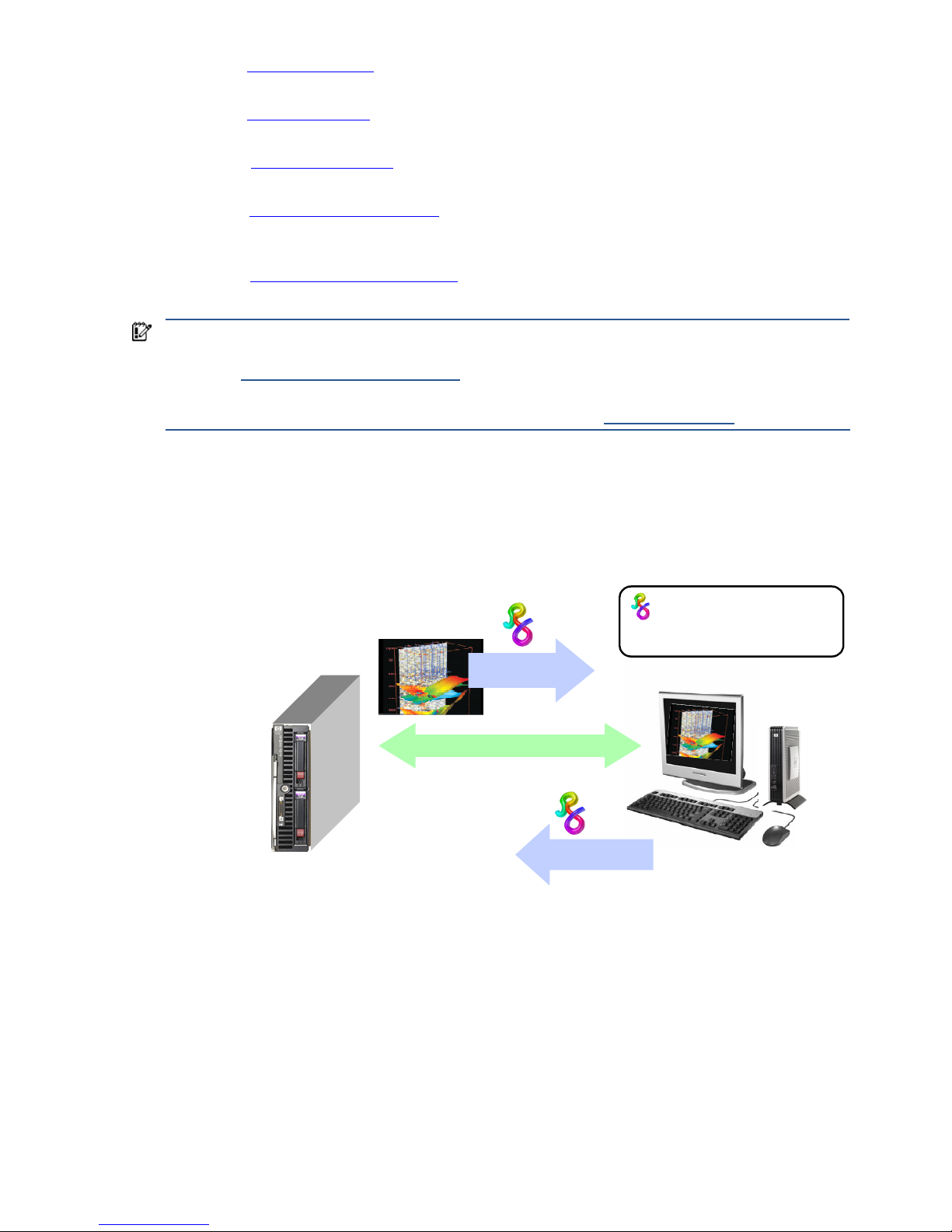
1-1 Typical RGS configuration
Figure 1-1 shows a typical RGS configuration, consisting of a blade workstation and a thin client. The user’s
applications run on the blade workstation while the user interacts with these applications from the thin client.
Figure 1-1 Typical RGS configuration
The blade workstation desktop image is transmitted over the network to the thin client, which displays the desktop
image locally in a window. RGS is designed to provide fast capture, compression, and transmission of the
desktop image over standard TCP/IP networks. RGS also captures user keyboard and mouse inputs from the thin
client, and sends them to the blade workstation for processing by Windows or Linux, and the applications running
on the blade workstation.
RGS also supports remote USB, which enables a user to connect USB devices to the thin client, and have the USB
devices accessible by the blade workstation. In addition, HP RGS supports remote audio, whereby audio output
from the applications is transported over the network for playback on the thin client.
TCP/IP network
interactive
desktop image
keyboard & mouse
inputs
HP ProLiant xw460c Blade Workstation
User applications run on
the blade workstation under
Windows XP Professional
HP Compaq t5720 Thin Client
This symbol denotes the HP RGS
product. The stylistic R stands
for “Remote” while the Greek gamma
symbol stands for “Graphics”.
Page 13
Introduction to HP Remote Graphics Software 13
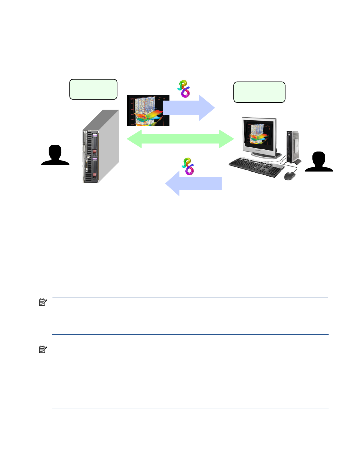
1-2 RGS Sender and Receiver
Figure 1-2 shows the two primary RGS software components, the RGS Sender and RGS Receiver. The RGS Sender
runs on the Remote Computer while the RGS Receiver runs on the Local Computer.
Figure 1-2 RGS Sender and Receiver
The Sender and Receiver provide the following functionality:
• Sender—Runs on the Remote Computer, and transmits graphics updates, audio, and USB data to the RGS
Receiver on the Local Computer. The RGS Sender receives and processes keyboard events, mouse events,
and USB data from the Receiver.
• Receiver—Runs on the Local Computer. The RGS Receiver establishes a connection to the Remote Computer,
requests graphics updates from the Remote Computer Sender, and displays the desktop of the Remote
Computer inside a window on the Local Computer. The RGS Receiver transmits keyboard and mouse events
to the RGS Sender.
The RGS Sender captures the actual screen pixels that are generated by the graphics adapter on the Remote
Computer. This process is often referred to as screen scraping, and operates independently of whether or not a
monitor is actually connected to the Remote Computer.
NOTE: HP RGS uses a pull model when establishing a connection, in contrast to a push model. With a pull model, the
connection is established by the Local Computer user, who uses the RGS Receiver to “pull” the connection from the
Remote Computer (RGS Sender). This is in contrast to a push model, where the Remote Computer would “push” the
connection to the Local Computer. The pull model is preferred because, in many cases, the Remote Computer (RGS
Sender) is operating unattended, and there is no user to establish a connection.
NOTE: Local user refers to the person physically located at the Local Computer. Remote user refers to the person
physically located at the Remote Computer (if, in fact, a person is present at the Remote Computer).
A local user who establishes an RGS login to the Remote Computer is known as the primary user. Once a primary
user has been established, another local user can view the Remote Computer desktop session using RGS only if
allowed by the primary user. There are situations, however, where a local user may replace the previous primary user
and become the new primary user.
The process by which a local user can become a primary user or view the primary user’s desktop is described in
detail in this guide.
TCP/IP network
interactive
desktop image
keyboard & mouse
inputs
HP ProLiant xw460c Blade Workstation
HP Compaq t5720 Thin Client
RGS Sender
RGS Receiver
Remote
Computer
Local
Computer
Remote User
(if present)
Local User
Page 14
Introduction to HP Remote Graphics Software 14
1-3 RGS features
HP RGS supports a number of features designed to optimize performance, security, and functionality (see Figure
1-3).
Figure 1-3 Features of HP RGS
• Application transparency—HP RGS supports application transparency, which enables applications to be run
on the Remote Computer, and accessed from the Local Computer, without modifications.
• Graphics acceleration hardware—Performance is enhanced because the applications running on the Remote
Computer use its graphics acceleration hardware.
• HP compression/decompression algorithms—Proprietary, high-performance HP image
compression/decompression algorithms enable real-time remote visualization that is visually lossless and
highly interactive.
• Selective screen updates—Only those portions of the screen which change are captured, compressed, and
transmitted from the Remote Computer to the Local Computer, further improving performance.
• Security—RGS supports many security features, including encryption of the pixel data sent from the Remote
Computer to the Local Computer.
• Collaboration—Multiple users can simultaneously connect to the same Remote Computer, allowing the users
to view and interact with the same desktop session and applications.
1-4 Additional RGS features
RGS provides many additional features, including:
• 3D application support—Users can interact with OpenGL 3D applications running on the Remote Computer.
Direct3D applications can be used as well, provided they are not in full-screen mode. 3D applications use
the full power of graphics acceleration hardware on the Remote Computer.
• Remote USB—USB devices connected to the Local Computer can be attached to, and accessed by, the
Remote Computer.
• Remote Audio—Smooth, continuous, low-latency, high-quality remote audio is transmitted from the RGS
Sender to the RGS Receiver.
TCP/IP network
HP ProLiant xw460c Blade Workstation
Remote
Computer
Local
Computer #1
Performance is enhanced through the
use of graphics acceleration hardware
HP-developed compression algorithms are used
to minimize data transmission requirements.
Security is provided through
encryption of the pixel data
sent over the network
Only those sections of the screen which
change are captured, compressed and
transmitted to the Local Computer.
Application
transparency
Collaboration – Multiple Local
Computers can connect to a
single Remote Computer, allowing
all users to simultaneously view
and sequentially interact
with the applications running
on the Remote Computer.
Local
Computer #2
Page 15

Introduction to HP Remote Graphics Software 15
• Audio follows focus—The RGS Receiver can be configured to enable audio for the session displayed in the
Remote Display Window that currently has focus, and is muted for all other remote sessions/windows.
• Directory Mode—Directory Mode enables the Receiver to look up a user’s pre-assigned computers from a
file.
• Easy Login—Enables fewer authentication steps when connecting to an HP blade workstation running
Windows XP.
• Single Sign-on—Enables fewer authentication steps and automatic login and unlocking of the desktop when
connecting to an HP workstation running Windows XP.
• Windows Event Logging—Network outages or loss of connectivity between a Receiver and Sender can leave
a desktop session running without supervision. To safeguard running applications, customer-designed agents
can monitor the status of connections to determine if termination of applications is required. Windows event
logging provides a mechanism for agents to determine the status of the connection between the Receiver and
Sender.
NOTE: See the RGS 5.3 data sheet for latest list of features.
1-5 Tabloid-size page
This guide contains a tabloid-size page that is best viewed either on your computer monitor or by printing it on
size B (11 inches by 17 inches) or ISO A3 (297 mm by 420 mm) paper. The tabloid page is included to permit a
complex diagram (Figure 5-10 on page 89) to be documented on a single page while maintaining read
ability. If
you print this document, it is recommended that you use a printer capable of handling letter and tabloid-size
paper simultaneously. If your printer handles only letter-size paper, you should specify, if available, scaling to
letter-size or scale-to-fit paper in the print dialog. This will cause the figure on the tabloid page to be scaled to fit
on the letter size paper.
The tabloid page may also be printed individually if you have access to a tabloid-capable printer. Go to page
89, select Current Page in the print dialog, and select Properties to view the paper size and orientation options.
Depending on your printer, paper size may be listed as tabloid, size B, or size A3. Orientation should be set to
landscape.
1-6 Obtaining HP technical support
If you encounter an issue that requires technical support, please do the following prior to contacting HP for
assistance:
• Be in front of the Local Computer or Remote Computer, whichever one is appropriate.
• Note the operating system.
• Note any applicable error messages.
• Note the applications you were using when you had the issue.
• Be prepared to spend the time necessary to troubleshoot the problem with the service technician.
For a listing of all worldwide technical support phone numbers, visit www.hp.com/support
, select your region,
and click Contact HP in the upper-left corner.
IMPORTANT: If your phone call is answered by a voice recognition system, and if you’re asked to provide the
name of the product, please say “Remote Graphics Software”, not “RGS”.
1-6-1 Software Service Strategy for Non-HP Hardware
RGS 5.3 and above is designed for and compatible with Microsoft Windows operating systems on hosted OS
Virtual Machine and physical machine environments.
• Windows XP Professional 32 and 64 bit
• Windows Vista Ultimate, Business and Enterprise 32 and 64 bit
RGS 5.3 is designed for and compatible with RHEL V4 and V5 32 and 64 bit operating environment on HP Blade
Workstations and HP Personal Workstations.
Page 16

Introduction to HP Remote Graphics Software 16
Telephone support service is for RGS software installation and configuration support.
• Customer must have a fully functioning system with standard Microsoft Windows software loaded and
running
Software patch updates are available through Software Depot at http://software.hp.com under Client
Virtualization.
Software assurance (enhancement upgrades) are available through separate Software Assurance products
1-6-2 Other RGS Documents
Other RGS documents such as the HP Remote Graphics Software Licensing Guide and the HP Remote Graphics
Software RGS Session Information Interface Specification can be found at:
http://www.hp.com/support/rgs_manuals
Page 17

RGS overview 17
2 RGS overview
Before exploring how to use RGS, it’s important to first understand the required system environments and security
features used and supported by RGS.
• Supported computers and operating systems
• RGS version numbering
• RGS licensing
• RGS products
• Sender and Receiver interoperability
• Application support
• Networking support
• RGS connection topologies
• One-to-one
• Many-to-one
• One-to-many
• RGS operating modes
• Multi-monitor configurations
• Remote USB operation
• Supported keyboards
• Security features
This chapter provides an overview of each of these features.
For a description of new features and other late breaking topics, see the README.txt file in the installation
directory of either the RGS Receiver or RGS Sender. The file is best viewed using Wordpad, Microsoft Word or
Openoffice swriter.
Page 18
RGS overview 18
2-1 Supported computers and operating systems
This section describes the computers and operating systems which support HP RGS 5.3.0 (see Figure 2-1). Any
RGS Sender can interoperate with any RGS Receiver.
Figure 2-1 Computers and operating systems that support RGS 5.3.0
Receiver
Support Matrix
Windows
XPe/WES
Windows XP Professional
SP1, SP2, SP3 32-BIT, X64
Windows Vista Business,
Ultimate and Enterprise 32-bit,
64-bit
Embedded
Linux
RHEL V4 (update 5 or later) V5
(update 2 or later) 32-bit, 64bit
Desktops
Personal
Workstations
X X HP xw and z series
Mobile
Workstations
X X
Desktop PCs X X
Notebook PCs X X
Performance Thin Clients
HP GT7725 HP ThinPro GT
HP GT7720 XPe
HP GT7720w WES
HP dc73 Blade WS
Client
HP Blade WS
Client
HP dc72 Blade WS
Client
HP Blade WS
Client
Mobile Thin Clients (may not be suitable for 720p and higher multi-media content)
HP 4410t WES
HP 6720t XPe
HP 2533t XPe
Flexible and Mainstream Thin Clients (may not be suitable for 720p and higher multi-media content)
HP t5730w WES
HP t5630w WES
HP t5730 XPe
HP t5630 XPe
HP t5720 XPe
HP t5545 HP ThinPro
Desktop receiver systems require 1.5 GHz or greater processor with SSE2 multi-media instruction extension, 32-bit color display adapter and 512 MB minimum RAM.
Sender Support
Matrix
Windows XP Professional SP1, SP2,
SP3 32-BIT, X64
Windows Vista Business, Ultimate and
Enterprise 32-bit, 64-bit
RHEL V4 (update 5 or later) V5 (update
2 or later) 64-bit
Blade Clients
HP Blade
Workstations
X X HP only
HP Blade PCs 32-bit only 32-bit, non-aero only
VDI Servers 32-bit hosted desktop 32-bit, non-aero only
Desktops
Personal Workstations X X HP only
Mobile Workstations X X
Desktop PCs X X
Notebook PCs X X
Desktop sender systems require 1.5 GHz or greater processor with SSE2 multi-media instruction extension, 32-bit color display adapter and 512 MB minimum RAM.
Microsoft Windows Vista Aero theme desktop running on a Sender requires an nVidia graphics card and a compatible nVidia driver.
Supported VDI Client Virtualization Software: VMware ESX 3.01, 3.02, 3.02 Update 1, ESX 3.03, ESX 3.5 Update 1, 2, 3, 4 and ESX 4.0.
In this document, references to “Windows” in the context of the RGS Sender refer to those Microsoft operating
systems in Figure 2-1 that support the RGS Sender. Similarly, references to “
Windows” in the context of the RGS
Receiver refer to those Microsoft operating systems in Figure 2-1 that support the RGS Receiver.
For more
information on HP products, please visit http://www.hp.com/support
Page 19
RGS overview 19
2-2 RGS version numbering
The RGS version (for example, version 5.3.0) contains the following three numbers:
1. Version major number
2. Version minor number
3. Version patch number
Figure 2-2 shows the positioning of the three
version numbers.
Figure 2-2 RGS version numbering
NOTE: Each patch release is a complete release of the entire RGS product, regardless of what components
have changed. For example, if a patch release is needed to make an RGS Sender security fix available, the
entire RGS product (including both the RGS Sender and Receiver) would be included in the patch release.
2-3 RGS licensing
IMPORTANT: RGS licensing applies to the RGS Sender only. The RGS Receiver is a free download and can be
used on any number of computers. Therefore, the following discussion of RGS licensing applies only to the RGS
Sender. For detailed information on RGS licensing, see the HP Remote Graphics Software Licensing Guide,
available at www.hp.com/support/rgs_manuals
.
Two types of licenses are supported by the RGS Sender:
• Local license file—With local licenses, each system running the RGS Sender requires a license file.
A license must be purchased and the license file installed for each RGS Sender computer.
• Floating licenses—With floating licenses, a pool of RGS licenses is purchased, which are dynamically
allocated on a first-come, first-serve basis whenever an RGS Receiver first attempts to connect to an RGS
Sender. In licensing terminology, a floating license is checked-out when a connection is established to the
RGS Sender, and is checked-in when the connection terminates. Floating licenses allow a company to
major.minor.patch
# # #
A major release contains sufficient changes
such that interoperability with the prior
major release is not guaranteed. For
example, Sender version 5.3.0 is not
guaranteed to interoperate with Receiver
version 4.2.0.
Patch releases are generated for a security
issue or for a major defect in a feature. A
patch release is indicated by this number
being non-zero
. Therefore, RGS 5.3.0 is not a
patch release. RGS 5.3.1 would be a patch
release.
RGS 5.3.0
Minor releases introduce new RGS features
and functionality. Minor releases will also
include (roll up) the changes in any prior
patch releases.
Page 20
RGS overview 20
purchase, for example, 75 licenses but support a user community of perhaps hundreds of users as long as
no more than 75 users ever attempt to establish an RGS connection simultaneously. Floating licenses
require a license server, which can be installed on one of the computers running the RGS Sender, or the
license server can be installed on a separate computer. The RGS product includes a setup.exe file that
installs the license server—see the HP Remote Graphics Software Licensing Guide, available at
www.hp.com/support/rgs_manuals
, for further details.
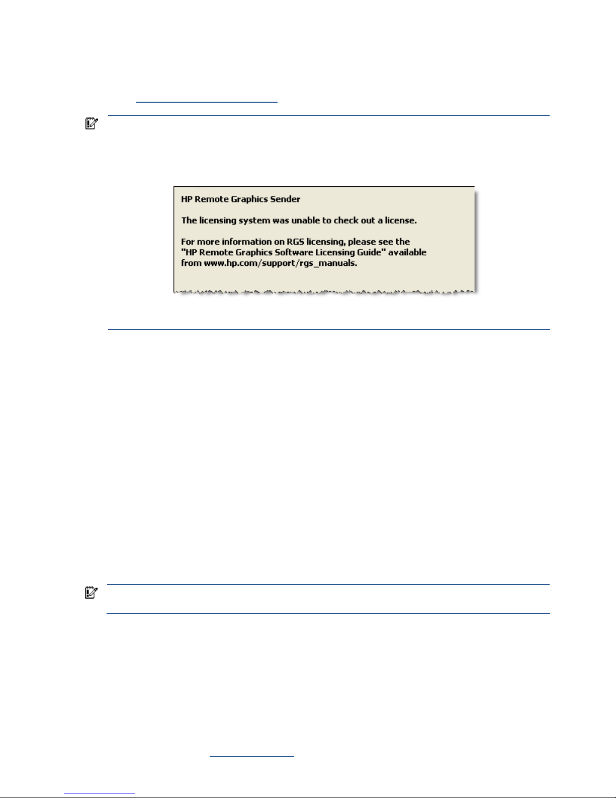
IMPORTANT: Prior to installing the RGS Sender license, you can still establish a connection from the Local
Computer to the Remote Computer, and can interact with the Remote Computer desktop. However, in the
absence of a license, the dialog shown in Figure 2-3 will be generated by the Remote Computer, and
display
ed in the window on the Local Computer that is showing the Remote Computer desktop.
igure 2-3 Dialog generated when the RGS Sender is unlicensed
This dialog cannot be moved or closed. Once the RGS Sender is licensed, the above dialog will no longer be
displayed.
2-4 RGS products
HP offers these RGS products:
1. HP RGS Desktop Trial Edition—HP offers a free, 60-day trial version of RGS Desktop; no license purchase is
required.
2. HP RGS VDI—This RGS product runs on HP and non-HP VMware VDI (Virtual Desktop Infrastructure) and HP
Blade PC platforms. HP RGS VDI uses a local license file key. A separate HP RGS VDI license is required for
each virtual machine using RGS.
3. HP RGS Desktop local license— This RGS product runs on all RGS supported platforms, including:
notebooks, desktop PCs, mobile workstations, personal workstations and HP blade workstations. In
addition, this key will also run on VMware VDI and HP Blade PC platforms that are supported by the RGS
VDI license key.
4. HP RGS Desktop floating license— This RGS product runs on all RGS supported platforms, including:
notebooks, desktop PCs, mobile workstations, personal workstations and HP blade workstations. In
addition, this key will also run on VMware VDI and HP Blade PC platforms that are supported by the RGS
VDI license key.
All RGS products include the same RGS Sender and the same RGS Receiver. The RGS Receiver is unlicensed and
can be installed on any number of computers.
IMPORTANT: Except for the 60-day HP RGS Desktop Trial Edition, the above RGS products never expire once
they are installed and licensed.
When you purchase RGS, you are entitled to free upgrades to all future patch releases. For example, if you
purchase RGS 5.3.0, you are entitled to a free upgrade to patch release 5.3.1, if available. In order to upgrade
to new enhancement releases, you must purchase RGS Software Assurance or re-purchase a new license at
upgrade time. To ensure you can download and install future minor and major releases (such as RGS 5.4 or 6.0),
HP offers the following 1 Year RGS Software Assurance products for each of the above RGS products (except the
HP RGS Desktop Trial Edition):
• 1 Year RGS Software Assurance—This product entitles you to upgrade to new major/minor releases of RGS
for one year from purchase date. The software assurance can be renewed annually at 25% of the internet
list price of a new license.
For more detailed information on the RGS products, see the HP Remote Graphics Software QuickSpec available
on the RGS homepage at www.hp.com/go/rgs
.
Page 21

RGS overview 21
2-5 Sender and Receiver interoperability
RGS provides interoperability between versions of RGS Senders and Receivers that have the same major version
number. For example, Sender version 5.0 and Receiver version 5.1 will interoperate together. However, Sender
version 4.2 is not guaranteed to interoperate with Receiver version 5.0. Connection between a Receiver and a
Sender should only be attempted when their major version numbers are the same. Beginning with RGS 5.3.0 the
Microsoft Windows Vista Sender added the capability to notify the Receiver prior to shutting down. The Microsoft
Windows Vista Sender must exit and then restart under several conditions such as: login, logoff, fast user
switching or Remote Desktop Protocol (RDP) transition. This behavior allows the Receiver to automatically
reconnect after the Sender has restarted. Receivers prior to 5.3.0 will show a pink or black screen and then a
Reconnect dialog box if the Sender has exited.
2-6 Application support
Except as noted in the next paragraph, RGS provides application transparency, meaning that the Local Computer
user, in executing applications on the Remote Computer, is typically unaware that the application is executing
remotely.
RGS supports all applications, except gaming applications and those applications that use full screen exclusive
mode. If a full-screen MS-DOS command prompt window is created on the Sender (using, for example,
command.com), the window will be reset to its default size by RGS. Likewise, if a full-screen Windows command
prompt window is created (using cmd.exe or the command prompt icon), the window will also be reset to its
default size by RGS. Full-screen DirectDraw applications are not supported (however, DirectDraw applications in
a Window may work, and should be qualified individually).
On Remote Computers running Linux, OpenGL-based applications can only be remoted if the Remote Computer is
using NVIDIA graphics.
2-7 Networking support
RGS uses TCP/IP over a standard computer network, and supports Ethernet connection speeds of
10/100/1000BASE-T (Gigabit). The RGS Sender listens on TCP/IP port 42966. The port used by the RGS
Receiver is assigned by the Local Computer OS and can vary. HP recommends full-duplex operation between the
Sender and Receiver. For information on using RGS through a firewall, see Section 4-4, “Using RGS through a
firewall.”
NOTE: At RGS 5.2.5, the capability was added to specify the port number used by the RGS Sender. The default
Sender port number is 42966, as noted above. The Sender port number can be changed using the
Rgsender.Network.Port property. If this property is used to change the Sender port number from its default value
of 42966, the Sender port number must then be specified in establishing an RGS connection from the Receiver to the
Sender.
2-8 Connection topologies
This section describes the connection topologies supported by RGS, such as how a single Local Computer may
connect to multiple Remote Computers.
2-8-1 The Remote Computer frame buffer
After making a connection between a Local Computer and a Remote Computer, the Remote Computer Sender
transmits its complete frame buffer to the Local Computer. The frame buffer is the memory on the Remote
Computer video adapter that holds the bitmapped image that is typically displayed on a monitor—for Windows
XP, the frame buffer contains the familiar Windows desktop (see Figure 2-4).
Figure 2-4 The Remote Comp
uter frame buffer containing the Windows desktop
Page 22
RGS overview 22
The monitor itself is optional on the Remote Computer. For example, if the Remote Computer is a Personal
Workstation, a monitor (plus a keyboard and mouse) would typically be attached. If the Remote Computer is an
HP ProLiant Blade Workstation, it is not possible to attach a monitor to view the primary (NVIDIA) frame buffer
because the video signal from the NVIDIA graphics adapter is not available on a connector—the contents of the
frame buffer can only be viewed remotely using RGS.
NOTE: For clarity in this guide, the bitmapped image contained in the Remote Computer frame buffer will often
be shown in association with the Remote Computer, independent of whether a monitor is actually connected
(or can be connected) to the Remote Computer.
2-8-2 One-to-one connection
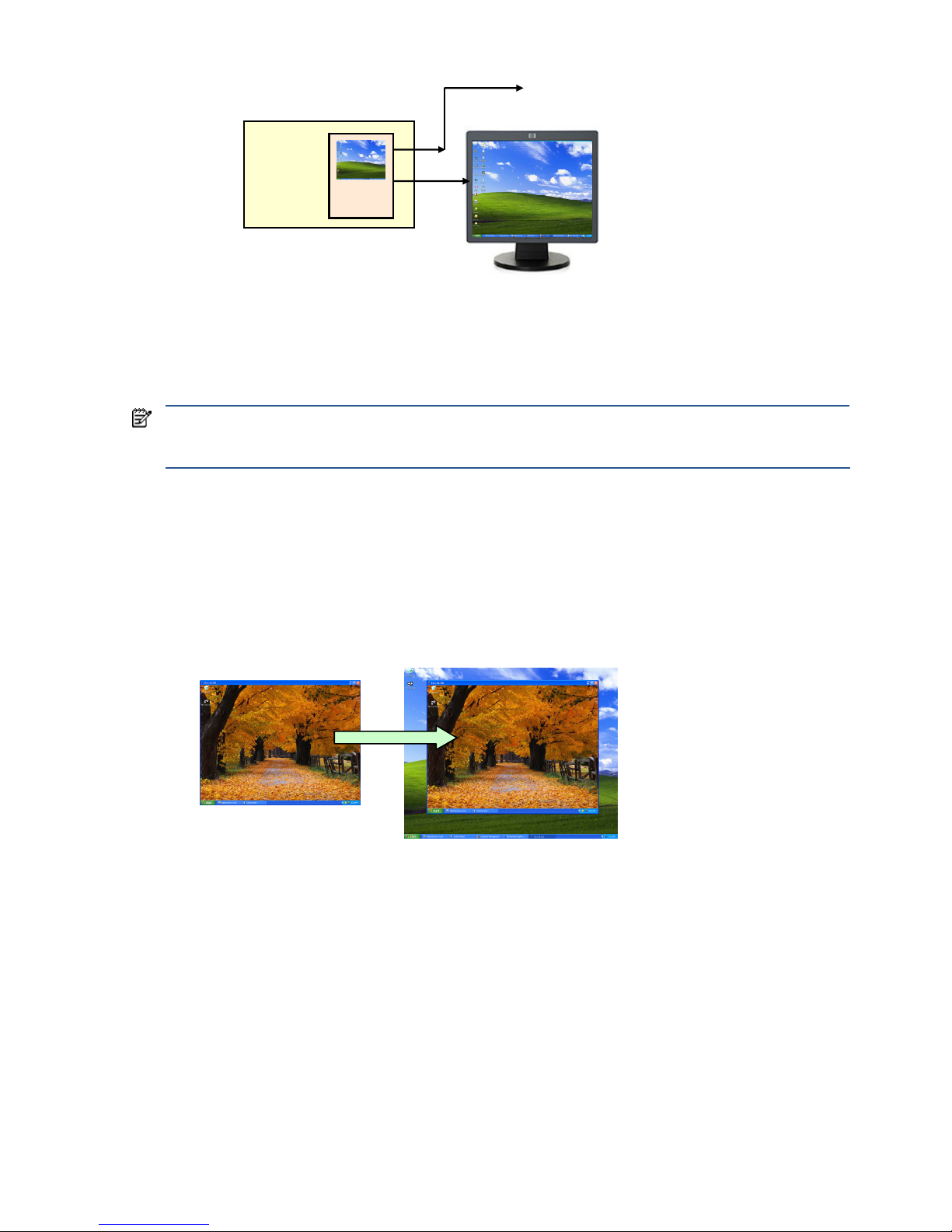
The simplest RGS connection is a single Local Computer making a connection to a single Remote Computer. The
entire frame buffer of the Remote Computer is displayed in a window on the Local Computer (see Figure 2-5). The
window on the Local Computer is called the Remote Display Window.
Figure 2-5 Display of the Remote Computer frame buffer on the Local Computer
In Figure 2-5, the Remote Computer frame buffer fits completely within the Remote Display Window on the Local
Computer monitor. However, it is possible for the Remote Computer frame buffer size to exceed the size of the
Local Computer monitor (as measured in horizontal pixels by vertical pixels). As before, the Remote Display
Window will be the size of the Remote Computer frame buffer. If the Remote Display Window is larger than the
Local Computer monitor, the window will extend off the monitor.
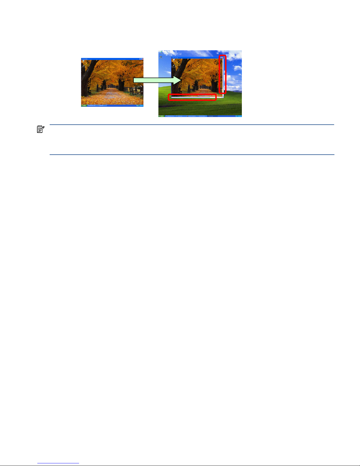
Regardless of the size of the Remote Display Window (that is, whether it fits on the Local Computer monitor or
extends off the monitor), if the local user resizes the Remote Display Window to be smaller than when it was
originally created, scroll bars will be added to allow the local user to view the complete Remote Computer frame
buffer (see Figure 2-6).
Remote
Computer
(optional)
frame
buffer
to Local Computer
TCP/IP
Remote Computer
(Sender)
Local Computer
(Receiver)
The entire frame buffer
of the Remote Computer
is mapped to a window
on the Local Computer,
called the Remote Display
Window.
Page 23
RGS overview 23
Figure 2-6 Addition of scroll bars if the Remote Display Window is resized smaller
NOTE: RGS does not provide a scale-to-fit capability to allow the contents of the Remote Computer frame buffer to be
scaled to fit the Local Computer monitor. If the Remote Computer frame buffer is larger than the Local Computer monitor,
the Remote Display Window will simply extend beyond the edges of the monitor. If the Remote Display Window is resized
to fit on the monitor, scroll bars will be added.
Remote Computer
(Sender)
Local Computer
(Receiver)
Scroll bars are created
if the Remote Display
Window is resized
smaller than when it
was originally created.
Page 24
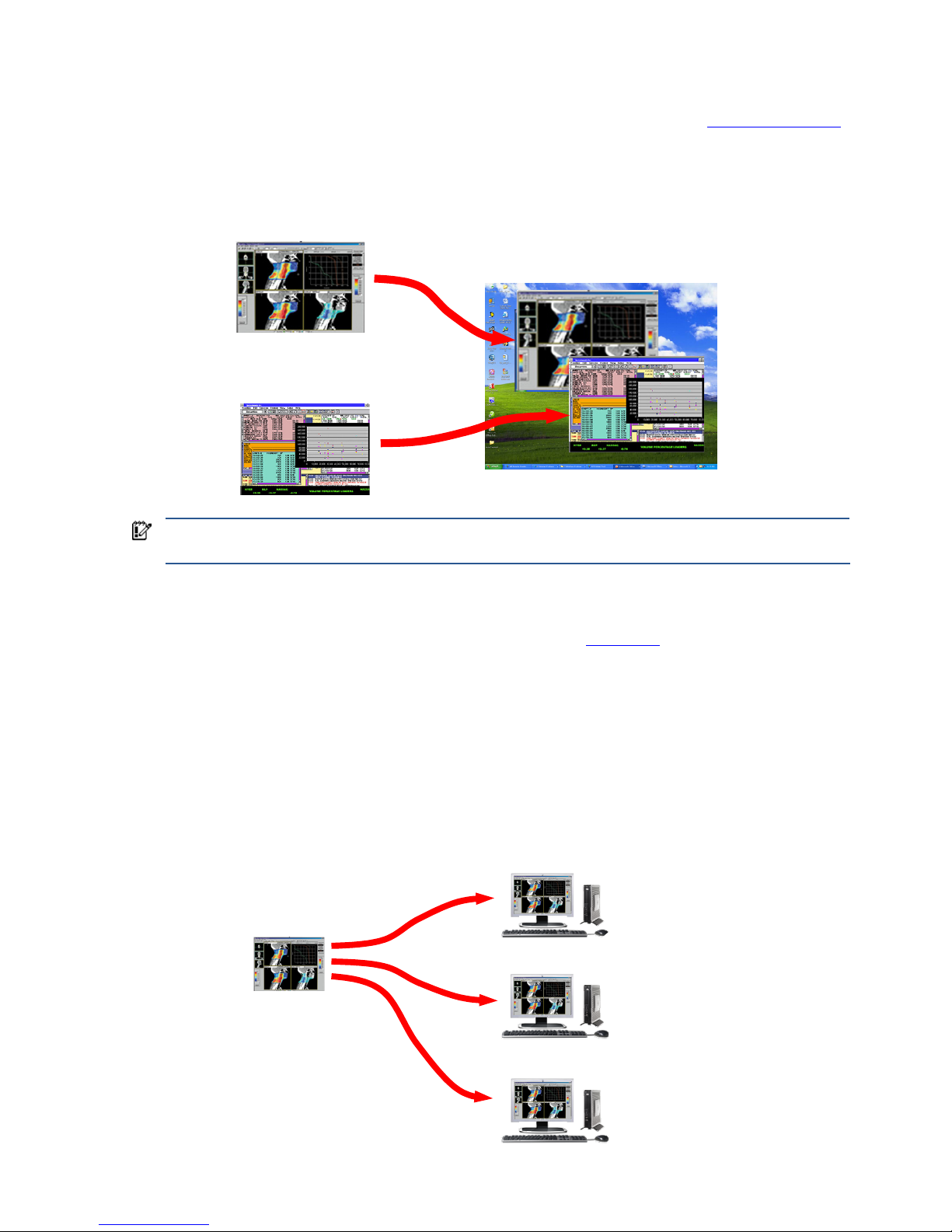
RGS overview 24
2-8-3 Many-to-one connection
The RGS Receiver supports a many-to-one connection, allowing a single Local Computer to connect to multiple
Remote Computers (see Figure 2-7), each running a desktop session—see Section 2-11, “RGS operating modes,”
specifically Directory Mode. The frame buffer of each Remote Computer is displayed in a separate Remote Display
Window on the Local Computer.
Figure 2-7 A Local Computer displaying two desktop sessions
IMPORTANT: Starting up two (or more) instances of the RGS Receiver to achieve a many-to-one connection is
not supported. Achieving a many-to-one connection is only supported through the use of Directory Mode.
The many-to-one connection capability allows implementation of a virtual KVM (keyboard, video, and mouse)
switch. The virtual KVM switch emulates the functionality of a standard KVM switch in software to provide a
convenient method to connect a single monitor, keyboard, and mouse (all on the Local Computer) to multiple
Remote Computers. Using the RGS Setup Mode (see Section 5-1-2, “Setup Mode
”), you can switch the local
monitor to display each of the Remote Computer frame buffers. The Receiver can also switch audio between active
sessions as described in the Controlling Receiver Settings section using the audio follows focus option.
2-8-4 One-to-many connection
RGS also supports a one-to-many connection, allowing the frame buffer of a Remote Computer to be displayed on
multiple Local Computers (see Figure 2-8). In this figure, there is one primary user who is logged into the Remote
Computer, and two local users
who are viewing the primary user’s desktop session on the Remote Computer.
Figure 2-8 Multiple users can access the desktop of a Remote Computer
Remote Computer
Local Computers
Primary User
Local User 1
If the Remote Computer
is a blade workstation,
it will typically not have
a monitor connected to
it. The above image
associated with the
Remote Computer is
for clarit y, to show
the source of the
desktop image
(logged into
Remote Computer)
(viewing primary
user’s desktop
session)
Local User 2
(viewing primary
user’s desktop
session)
Remote Computer 1
Remote Computer 2
Local Computer
Page 25
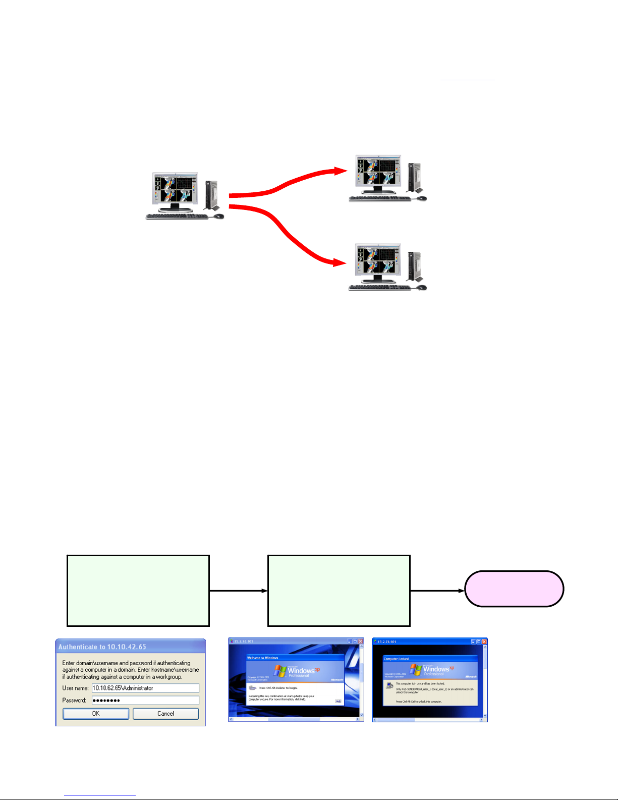
RGS overview 25
The one-to-many configuration is ideal for collaboration because each user can interact with the applications
running on the Remote Computer (subject to RGS policies which arbitrate which user is able to provide keyboard
and mouse inputs to the Remote Computer at any particular time). As one user interacts with the applications on
the Remote Computer, all other users can view these interactions. See Section 5-5, “Collaborating
,” for details.
In the previous example, it was assumed that the primary user and the local users were all physically separate
from the Remote Computer. This, however, doesn’t have to be the case. RGS works equally well sharing between
workstations (see Figure 2-9).
Figure 2-9 Shari
ng between workstations
In Figure 2-9, the primary user is directly logged into the Remote Computer using its attached keyboard, mouse
and monitor. In other words, the primary user is physically present at the Remote Computer, while local user 1
and local user 2 are physically separate from the Remote Computer. RGS can be used by local users 1 and 2 to
connect to the primary user’s desktop
2-9 Establishing an RGS connection using Standard Login
In normal operation, users are required to authenticate twice when establishing an RGS connection from a Local
Computer to a Remote Computer. This is the Standard Login process—the two steps are:
1. The first authentication step is from the RGS Receiver to the RGS Sender—this is called authenticating the
RGS connection. The dialog for this authentication step is generated and displayed by the RGS Receiver on
the Local Computer.
2. The second authentication step is when logging into or unlocking the Remote Computer desktop session—this
is called logging into the Remote Computer. The login or unlock dialog is generated by the Remote
Computer, and is displayed in the Remote Display Window on the Local Computer.
Figure 2-10 shows the two-step Standard Login RGS connection process.
Figure 2-10 Standard Login process
Remote Computer
Primary User is
logged into the
computer using
its attached
keyboard, mouse
and monitor.
Local User 1
(viewing primary
user’s desktop
session)
Local User 2
(viewing primary
user’s desktop
session)
Step 1: Authenticating
the RGS connection
Step 2: Logging into
the Remote Computer
RGS Connection
Page 26
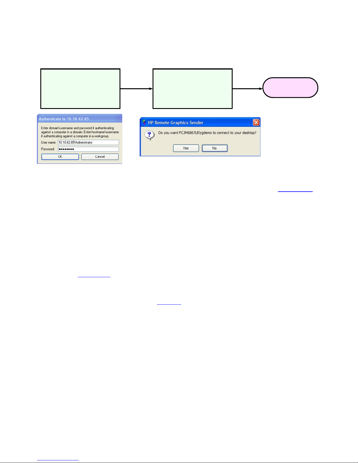
RGS overview 26
If another user is already logged into the Remote Computer, the second authentication step is replaced by an
authorization step, in which the currently logged-in user receives an authorization prompt to allow or disallow the
new user to join (connect to) the existing desktop session (see Figure 2-11). The new user is allowed to connect to
the existing RG
S connection only if the currently logged-in user authorizes the connection.
Figure 2-11 RGS connection process if another user is already logged into the Remote Computer
There are a number of variations of the Standard Login process, as detailed in Section 5-3-1, “Standard Login
.”
2-10 Single Sign-on and Easy Login
RGS supports two additional login methods on certain Windows-based Remote Computers. These login methods
are currently only supported on Windows XP sender platforms. These two methods allow users to enter their
credentials only once in connecting to a Remote Computer—these methods are described below, along with
which authentication process is used:
• Single Sign-on—The RGS connection authentication process is used (step 1 in Figure 2-10 and Figure 2-11).
If authentication is successful,
the user will immediately see the Windows desktop session without needing to
explicitly log into Windows or unlock the desktop. Single Sign-on is described further in Section 5-3-3,
“Single Sign-on
.”
• Easy Login— The user is pre-connected to the system and standard Windows login screens are used to login
to the desktop or unlock the screen. If Windows authentication is successful, the user will immediately see the
desktop session without needing to be first authenticated by the RGS Receiver/Sender. Easy Login is
described further in Section 5-3-2, “Easy Login
.”
If neither Single Sign-on nor Easy Login is selected, the default Standard Login will be used. In terms of selecting
between Single Sign-on and Easy Login, two factors to consider are:
• If Single Sign-on is used with HP Session Allocation Manager (SAM), the user will only need to enter their
credentials once to connect to multiple Remote Computers. The credentials are entered when authenticating
with SAM—thereafter, each RGS connection is automatically authenticated, and a Remote Display Window
from each Remote Computer is automatically displayed on the Local Computer.
• Easy Login supports GINA (Graphical Identification and Authentication) chaining, allowing custom 3
rd
party
login mechanisms to be integrated into RGS. Single Sign-on does not support chaining of 3rd party GINA
modules.
For example, a 3
rd
party fingerprint reader will typically install a custom GINA module. The GINA module
will allow the user to be authenticated through their standard username/password mechanism (because the
GINA modules are chaining) or with their fingerprint. The fingerprint reader would be physically attached to
the Local Computer but would be logically connected to the Remote Computer using remote USB. If Easy
Login is used, only a single login step is required—the fingerprint reader will provide the credentials for
logging into the Remote Computer.
Step 1: Authenticating
the RGS connection
Step 2: Authorization
by the currently-logged
in user
RGS Connection
Displayed on the Local Computer
Displayed for the currently-logged in user
Page 27

RGS overview 27
2-11 RGS operating modes
RGS supports two basic operating modes:
1. Normal Mode—This mode enables RGS to connect to a single Remote Computer, as described in Section 2-
8-2, “One-to-one connection
.” Normal Mode is described in Chapter 5, “Using RGS.”
2. Directory Mode—This mode enables RGS to connect to multiple Remote Computers, as described in Section
2-8-3, “Many-to-one connection
.” Directory Mode is based on a user-created file which specifies which
Remote Computers the RGS Receiver should connect to. Directory Mode is described in Chapter 7, “Using
Directory Mode.”
NOTE: Prior to RGS 5.2.0, RGS supported a third operating mode—Enterprise Service Mode. Enterprise
Service Mode was based on the creation of a network service which specified which Remote Computers the
RGS Receiver should connect to. Enterprise Service Mode has been superseded by HP Session Allocation
Manager (SAM), and therefore has been discontinued as of the RGS 5.2.0 release.
Page 28
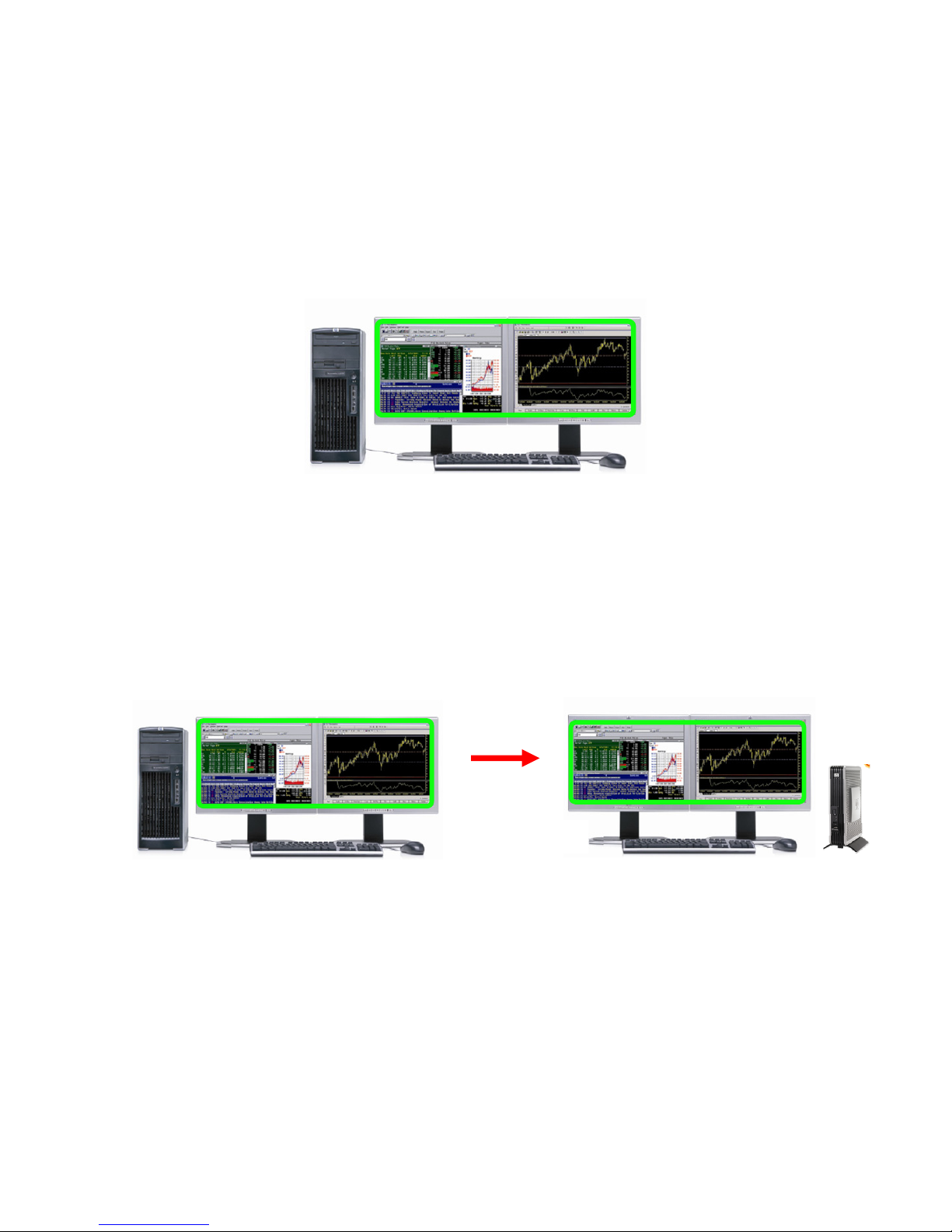
RGS overview 28
2-12 Multi-monitor configurations
Many computers have a frame buffer that is larger in size (as measured in horizontal pixels by vertical pixels) than
what can be displayed on a single monitor. In these situations, the default operation is that a portion of the frame
buffer is used, allowing the utilized portion (containing the Windows desktop) to be displayed on a single
monitor. It is possible, however, to configure a computer so that the Windows desktop occupies the complete
frame buffer—this typically requires multiple monitors to view the complete frame buffer (Windows desktop).
In Figure 2-12, the Windows desktop is configured to occupy
the complete frame buffer of the Remote Computer,
which, for this particular Remote Computer, requires two monitors to display the Windows desktop.
Figure 2-12 Remote Computer frame buffer requires two monitors to view the Windows desktop
When a Local Computer establishes an RGS connection to the Remote Computer of Figure 2-12, the Remote
Computer will, as usual, transmit its complete frame buffer. In order for the local user to view the complete desktop
of the Remote Computer, the Local Computer must have a comparably-sized frame buffer, which will typically
require two monitors to view (see Figure 2-13 ).
Figure 2-13 A Remote Display Window spanning two
monitors
Remote Computer
(Sender)
Frame buffer containing the Windows
desktop requires two monitors for display
Remote Computer
(Sender)
The frame buffer containing the Windows
desktop requires two monitors for display
Local Computer
If the Local Computer desktop expands across two
monitors, RGS will be able to create a Remote
Display Window that displays t he complete Remote
Computer fram e buffer.
Page 29
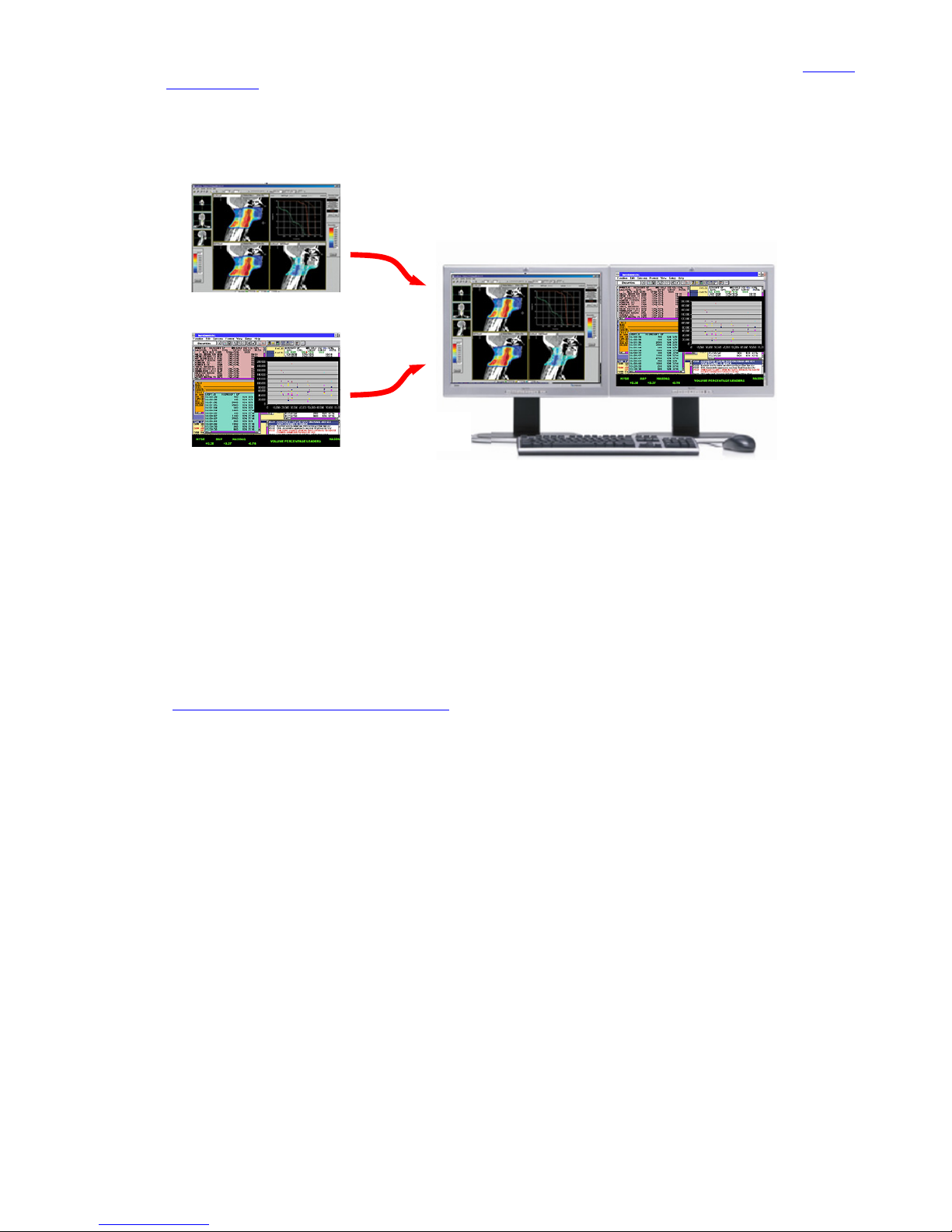
RGS overview 29
Multiple monitors on the Local Computer are also useful in the configuration described in Section 2-8-3, “Many-to-
one connection.” If the Local Computer is connected to two Remote Computers, each Remote Computer frame
buffer can be displayed on its own monitor if the Local Computer has two monitors (see Figure 2-14).
Figure 2-14 Each Remote
Display Window can be positioned to occupy a single monitor
As always, each Remote Computer (Sender) frame buffer is displayed in its own Remote Display Window. In
Figure 2-14, the user has positioned each Re
mote Display Window to occupy a single monitor, achieving the
result that the left monitor is dedicated to Remote Computer 1 while the right monitor is dedicated to Remote
Computer 2.
2-13 Remote Computer monitor blanking overview
New in RGS 5.0, this feature blanks the Remote Computer monitor (if one is connected) when the local user
establishes an RGS connection to the Remote Computer and logs in—in other words, becomes the primary user.
This feature is provided for security, to ensure that the primary user’s desktop session on the Remote Computer is
not visible on a monitor connected to the Remote Computer. For details on monitor blanking, see Section 5-1-4,
“Remote Computer monitor blanking operation
.”
2-14 Video overlay surfaces
When the Windows Sender is installed on a computer, video overlay surfaces (also known as overlay planes) are
disabled on the computer. Some media players that use video overlay surfaces will not display correctly. This can
often be resolved by disabling the use of video overlay surfaces in the media player.
Most OpenGL applications will detect the disabling of overlay surfaces, and will work correctly. However, if your
OpenGL application attempts to use the disabled overlay surfaces, it may display incorrectly. If this is the case,
check to see if your OpenGL application provides a mechanism for the user to manually disable the use of overlay
surfaces.
Remote Computer 1
Remote Computer 2
Local Computer
Page 30
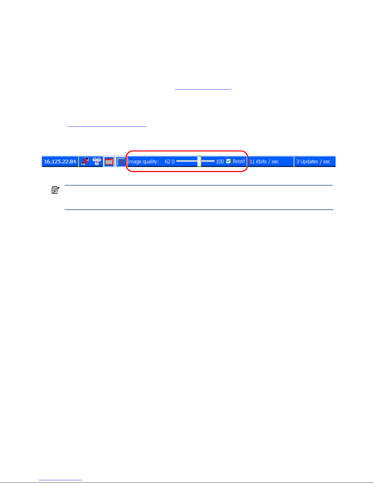
RGS overview 30
2-15 Image quality
RGS provides high-quality, high-performance image compression and decompression. Image compression is
performed on the Remote Computer to reduce the network bandwidth requirements—this enables RGS to be used
on standard networks. Image decompression is performed on the Local Computer.
RGS supports setting of the Image quality on a per-Receiver basis. Image quality is adjusted using the slide bar in
the Remote Display Window Toolbar (see Figure 2-15). As the image quality is increased toward 100, the amount
of c
ompression decreases, and the required network bandwidth increases. If a Receiver is supporting multiple
Remote Display Windows (see Section 2-8-3,”Many-to-one connection
”), the slide bar in any Remote Display
Window Toolbar can be adjusted—the slide bars in the other Remote Display Windows will automatically track.
The Boost checkbox was added beginning with RGS 5.2.6, and requires that both the RGS Sender and Receiver
be version 5.2.6 or later. Checking the Boost checkbox will improve (boost) image quality for certain types of
images, primarily images containing significant amounts of text or lines. For further information, see Section 5-1-3,
“Remote Display Window Toolbar
.”
Figure 2-15 Image quality slide bar in the Remote Display Window Toolbar
NOTE: Even with an image quality of 100, RGS still performs some image compression to reduce the network
bandwidth requirements. While the image quality on the Receiver will usually appear visually lossless to the
user, the actual image data sent over the network will be “lossy” to a limited extent.
Page 31

RGS overview 31
2-16 Remote USB overview
RGS supports remote USB, which allows USB devices connected to the Local Computer (local USB devices) to be
attached to a Remote Computer. Remote USB is supported on Remote Computers running Windows, and enables
the Remote Computer to have direct access to the local USB devices as if they are connected directly to the
Remote Computer (see Figure 2-16). For details on remote USB, see Section 6-3, “Remote USB operation
.”
Figure 2-16 Remote Computer can access the local USB devices
In Figure 2-16, two USB devices are connected to the Local Computer. Using RGS, the local USB devices can be
attached to the Remote Computer. The keyboard and mouse always remain connected to the Local Computer, and
cannot be attached to the Remote Computer.
The local USB devices can be collectively attached to a single Remote Computer (see Figure 2-17). The local USB
devices cannot
be split between multiple Remote Computers nor can they be collectively attached to multiple
Remote Computers.
Figure 2-17 The local USB devices can be attached to only one Remote Computer at a time.
2-16-1 USB session switching
At RGS 5.1.3, the ability to dynamically move USB devices from one Remote Computer to another was added.
Prior to RGS 5.1.3, it was necessary to first disconnect all RGS connections (sessions) to the Remote Computers,
and then re-establish connections while specifying a new Remote Computer to attach the USB devices to. With
RGS 5.1.3, USB devices can be detached from one Remote Computer, and made accessible by another Remote
Computer without first needing to disconnect the RGS connections. For details on this, see Section 6-3, “Remote
USB operation.”
2-16-2 Isochronous USB support
At RGS 5.2.0, support was added for the USB isochronous data type, which is commonly used for streaming data
devices such as audio and video devices. See Appendix B: USB devices supported by RGS for a list of supported
isochronous USB devices. See also Section 2-17-3, “Support of sound recording devices on Windows
,” for an
overview of the two ways USB microphones can now be used with RGS.
Remote
Computer 1
Local Computer
Keyboard & mouse
always connected
to Local Computer
USB
1
USB
2
Remote
Computer 2
Remote
Computer
Local Computer
Keyboard & mouse
always connected
to Local Computer
USB
1
USB
2
Page 32

RGS overview 32
2-16-3 Install-time configuration of remote USB
This section provides an overview of install-time configuration of remote USB—see Chapter 3, “Installing RGS,” for
more details.
NOTE: The Remote USB configuration cannot be changed after installation of the Sender and Receiver—to
select a different USB configuration option, the Sender or Receiver must be uninstalled and reinstalled.
During installation of the RGS Receiver, you can select one of three Remote USB Configuration options (see Figure
2-18).
Figure 2-18 Receiver installation dialog to specify the Remote USB Configuration
The three Remote USB Configuration options are:
1. USB devices are Local—All USB devices will remain local, and will be accessible only by the Local
Computer—none of the USB devices will be accessible by a Remote Computer.
2. USB devices are Remote—All USB devices can be accessed by the Remote Computer, and none of the USB
devices can be accessed by the Local Computer.
3. USB devices are Local/Remote—Whether USB devices are locally or remotely accessible depends on when
they are plugged into the Local Computer relative to establishment of an RGS connection (see Figure 2-19).
IMPORTANT: In addition to the general default settings for remote USB configurations, RGS 5.2.6 and
higher releases support auto-remote and auto-return of user-specified USB devices when using Windows
on both the sender and receiver platforms. Auto-remote allows specified USB devices to be automatically
attached to a remote sender session at RGS connection and then returned to the local client at RGS
disconnect.
For information on how to modify the Registry to support auto-remoting; see Auto-remoting of USB devices
Page 33

RGS overview 33
Figure 2-19 USB device accessibility for the setting “USB devices are Local/Remote”
As can be seen in
Figure 2-19, USB device accessibility depends on when the USB device is plugged into the Local Computer.
If a USB device is inserted while no RGS connection is established, the device will be locally-accessible only.
If a USB device is inserted while an RGS connection is established, the device will be remotely-accessible
only.
Once a USB device is established as locally-accessible or remotely-accessible, its status can only be
changed by removing and inserting the device while in the alternate RGS connection state (either connected
or not connected). For example, to make a locally-accessible USB device remotely accessible, the USB
device needs to be removed and inserted after an RGS connection is established.
2-16-4 Unique smartcard handling
New with RGS 5.1.3 is unique handling of USB smartcard readers, including Common Access Card (CAC)
readers. Prior to RGS 5.1.3, smartcard readers were handled in the same manner as other USB devices, as
described above. With RGS 5.1.3, smartcard readers are now handled in a unique manner, as follows:
• Unique smartcard handling requires, on the Sender, that Easy Login be enabled and that the chaining GINA
module msgina.dll be utilized
• Unique smartcard handling also requires that the Local and Remote Computers both be running Windows.
• For USB configuration settings USB devices are Remote and USB devices are Local/Remote, smartcard
readers will always be accessible by the Local Computer prior to establishing a connection to a Remote
Computer. This is to allow the smartcard reader to be used by the Local Computer prior to using the
smartcard to authenticate access to the Remote Computer.
• Figure 2-20 shows the local and remote accessibility of the s
martcard reader for USB configuration settings
USB devices are Remote and USB devices are Local/Remote. In both cases, smartcard readers will be locally
accessible prior to establishing an RGS connection, and will be remotely accessible once an RGS
connection is established.
power-on RGS connection
established
USB device #1
plugged in
USB devi ce #2
plugged in
USB device #3
plugged in
These devices will only be locally
accessible (never remotely) because
they were plugged in while no RGS
connection was established.
Device #3 will be remotely accessible
because it was plugged in during an
RGS connection. This device will be
remotely accessible during the current
RGS connection and any subsequent
RGS connections.
USB devices are Local/Remote
RGS connect ion RGS connection
Device #3 will not be accessible, either locally or
remotely, during breaks in the RGS connection.
Page 34

RGS overview 34
Figure 2-20 Smartcard reader accessibility pre- and post-RGS connection for settings “USB devices are Remote”
or “USB devices are Local/Remote”
• Figure 2-20 indicates that the USB devices are Remote and USB devices are Local/Remote settings are
effectively ignored for smartcard readers. In particular, the USB devices are Remote setting is ignored as
evidenced by the smartcard reader being locally accessible prior to establishment of an RGS connection.
Similarly, the USB devices are Local/Remote setting is ignored as evidenced by the locally-accessible
smartcard reader automatically becoming remotely accessible once an RGS connection is established.
• If a smartcard reader is plugged in after an RGS connection is established, it will be available remotely.
• If there is a break in the RGS connection, the smartcard reader will become locally accessible.
If Microsoft Remote Desktop Connection (RDC) is used to connect from the Local Computer to the Remote
Computer, it’s possible to get into a situation where the smartcard reader can’t be used to log into the Remote
Computer (for details on the interoperability of RGS and RDC, see Section 2-19, “Interoperability of RGS and
Microsoft Remote Desktop Connection“). This situation can arise as follows:
1. The user uses a smartcard reader to log into the Remote Computer with RDC. Assume that this login session
is established from the user’s home.
2. Assume further that the user inadvertently leaves the RDC login session established, and departs for work.
3. From work, the user attempts to log into the Remote Computer with RGS using an at-work smartcard reader
in Easy Login mode (which is required for the smartcard reader, as noted previously). Because the home
RDC login session is still active, RGS will require the user to authenticate the connection (which is not
normally required with Easy Login).
However, the user may not have a login name and password—the user may be totally relying on smartcard
readers at home and at work to log into the Remote Computer. If the user is unable to authenticate the
connection with a user name and password, the USB smartcard reader will not be remotely mounted to the
Remote Computer, and the user will not be able to log into the Remote Computer.
4. To prevent this situation, the user should log out from the RDC session prior to leaving home.
5. To address this situation if it occurs, the user can do one of the following:
• Contact IT, and have an administrator log into the Remote Computer with RGS, which will terminate the
RDC connection. After the administrator disconnects the RGS connection, the user can establish an RGS
connection using the smartcard reader.
• Reboot the Remote Computer.
• Return home, and log out from the RDC session.
NOTE: Unlike RDC, a user can leave a home RGS login session active, and then log in from work with RGS. The
smartcard reader will operate correctly in both situations, and the work RGS login session will replace the home login
session. However, before departing for work, the user must disconnect the RGS connection. If the home RGS connection is
left active, Easy Login will not work from work, and the user will be required to perform steps similar to the steps in
paragraph 5 to be able to log in from work.
power-on
RGS connection
established
smartcard reader
plugged in
smartcard
plugged in
smartcard reader
plugged in
Smartcard reader will
be locally accessible.
USB devices are Remote
or
USB devices are Local/Remote
Smartcard reader will be
remotely accessible.
Smartcard reader will automatically
become remotely accessible.
RGS connection RGS connection
Smartcard reader will be locally accessible
during breaks in the RGS connection.
Page 35

RGS overview 35
2-16-5 Computers supporting remote USB
Remote USB connections are supported by the computers and operating systems shown in Figure 2-21.
Figure 2-21 Configurations supporting remote USB
Receiver Remote USB
Support Matrix
Windows
XPe/WES
Windows XP Professional SP1, SP2,
SP3 32-BIT, X64
Windows Vista Business, Ultimate and
Enterprise 32-bit, 64-bit
Embedded
Linux
Personal Workstations X X
Mobile Workstations X X
Desktop PCs X X
Notebook PCs X X
HP GT7725 HP ThinPro GT
HP GT7720 XPe
HP GT7720w WES
HP dc73 Blade WS Client HP Blade WS
Client
HP dc72 Blade WS Client HP Blade WS
Client
HP 4410t WES
HP 6720t XPe
HP 2533t XPe
HP t5730w WES
HP t5630w WES
HP t5730 XPe
HP t5630 XPe
HP t5720 XPe
HP t5545 HP ThinPro
Sender Remote USB Support
Matrix
Windows XP Professional SP1, SP2, SP3 32-BIT,
X64
Windows Vista Business, Ultimate and Enterprise 32-bit, 64bit
HP Blade Workstations X X
HP Blade PCs 32-bit only 32-bit, non-aero only
VDI Servers 32-bit hosted desktop 32-bit, non-aero only
Personal Workstations X X
Mobile Workstations X X
Desktop PCs X X
Notebook PCs X X
2-16-6 Supported USB devices
HP has tested a number of USB devices to verify they work correctly when attached to a Remote Computer from a
Local Computer. See Appendix B: USB devices supported by RGS for a list of supported USB devices.
2-17 Remote audio overview
This section describes RGS support of remote audio on Windows and Linux. Rather than describe all four
combinations of Remote and Local Computers running Windows and Linux, the following sections describe remote
audio when both computers are running Windows, followed by a remote audio description when both computers
are running Linux.
Page 36

RGS overview 36
2-17-1 Remote audio on Windows
RGS on Windows supports remote audio, allowing audio generated by the application on the Remote Computer
to be captured and transmitted to the Local Computer for playback. In addition, microphone input on the Local
Computer running Microsoft Windows XP can be sent to the application running on the Remote Computer also
using Microsoft Windows XP. Remote microphone is not supported on Microsoft Windows Vista. Figure 2-22
shows the RGS
audio subsystem (green boxes) for Windows, and the audio data paths—these data paths are
described in Table 2-1.
Figure 2-22 RGS audio subsystem on Windows
Table 2-1 describes each of the audio data paths. The numbering and lettering in the table correspond to the
numbering and lettering in Figure 2-22.
Table 2-1 Windows RGS audio data paths
Audio Playback from the Remote Computer to the Local
Computer
Sending of microphone audio from the Local Computer to
the Remote Computer
Application
RGS Audio Player
HP Remote Microphone
virtual device
audio device
analog
microphone
RGS Audio
Recorder
USB
microphone
RGS Audio
Recorder
RGS Audio
Player
Application
mixer
HP Remote Audio
virtual device
audio device
Windows
Remote Computer
Windows
Local Computer
1
3
5
6
7
8
ab
c
d
2
4
1 8
_
Playback of audio
generated by the
Remote Computer
application
a
_
d
Microphone audio sent
to the Remote Computer
application
Paths
Paths
Path when USB
devices are remote
Remote
USB driver
Path when USB
devices are local
Page 37

RGS overview 37
Table 2-1 Windows RGS audio data paths
Audio Playback from the Remote Computer to the Local
Computer
Sending of microphone audio from the Local Computer to
the Remote Computer
1. The application-generated audio output.
2. If an audio device is installed, the applicationgenerated audio is routed through it.
3. If there is no audio device (such as with a blade
workstation), the HP Remote Audio virtual
device is automatically installed, and the
application-generated audio is routed to it.
4. Audio from either the audio device or the HP
Remote Audio virtual device is sent to the RGS
Audio Recorder.
5. The RGS Audio Recorder captures the audio,
which is sent by RGS to the Local Computer.
6. The RGS Audio Player on the Local Computer
decodes the received audio, and sends it to the
audio mixer.
7. The output of the audio mixer is sent to the Local
Computer audio device.
8. The audio device drives an audio output device,
such as a speaker.
USB devices are Local:
a. The user selects the microphone source, either a USB
microphone or an analog microphone. The RGS
Audio Recorder captures the selected microphone
source.
b. The audio captured by the RGS Audio Recorder is
sent by RGS to the RGS Audio Player on the Remote
Computer.
c. The RGS Audio Player decodes the audio signal, and
sends it to the HP Remote Microphone virtual device.
d. The HP Remote Microphone virtual device appears to
the application as a local microphone, and sends the
microphone audio to the application.
USB devices are Remote: Beginning at RGS 5.2.0, certain
USB microphones can be mounted to the Remote
Computer using the remote USB driver—see Appendix B
for the supported microphones. See the previous section
for a description of Remote USB operation.
Page 38

RGS overview 38
2-17-2 Remote audio on Linux
RGS on Linux also supports remote audio, allowing audio generated by the application on the Remote Computer
to be captured and transmitted to the Local Computer for playback (presuming the Remote Computer has a
physical audio device installed). In addition, microphone input on the Local Computer can be sent to the
application running on the Remote Computer. However, unlike Windows, microphone input on Linux can be
provided only via the remote USB driver. Figure 2-23 shows the RGS audio subsystem (gree
n boxes), and the
audio data paths for Linux—these data paths are described in Table 2-2. To simplify comparison with Windows,
all audi
o components shown on the Windows diagram in Figure 2-22 are retained below, but partially obscured
if not supported on Li
nux.
Figure 2-23 RGS audio subsystem on Linux
Table 2-2 describes each of the audio data paths. The numbering and lettering in the table correspond to the
numbering and lettering in Figure 2-23. For a list of audio devices supported on Li
nux Remote Computers, see
“Appendix C: Linux remote audio device support
.”
Table 2-2 Linux RGS audio data paths
Audio Playback from the Remote Computer
to the Local Computer
Sending of microphone audio from the Local
Computer to the Remote Computer
Application
RGS Audio Player
HP Remote Microphone
virtual device
audio device
analog
microphone
RGS Audio
Recorder
RGS Audio
Recorder
RGS Audio
Player
Application
mixer
HP Remote Audio
virtual device
audio device
Linux Remote Computer
Linux Local Computer
1
3
5
6
7
8
ab
c
d
2
4
1 8
_
Playback of audio
generated by the
Remote Computer
application
a
_
d
Microphone audio sent
to the Remote Computer
application
Paths
Paths
Remote
USB driver
USB
microphone
Path when USB
devices are remote
Path when USB
devices are local
Page 39

RGS overview 39
Table 2-2 Linux RGS audio data paths
Audio Playback from the Remote Computer
to the Local Computer
Sending of microphone audio from the Local
Computer to the Remote Computer
1. The application-generated audio output.
2. If an audio device is installed, the application-generated
audio is routed through it. Note that blade workstations do
not contain audio devices—therefore, audio playback is not
supported on blade workstations.
3. The HP Remote Audio virtual device is not supported on Linux.
4. Audio from either the audio device is sent to the RGS Audio
Recorder.
5. The RGS Audio Recorder captures the audio, which is sent by
RGS to the Local Computer.
6. The RGS Audio Player on the Local Computer decodes the
received audio, and sends it to the audio mixer.
7. The output of the audio mixer is sent to the Local Computer
audio device.
8. The audio device drives an audio output device, such as a
speaker.
USB devices are Local: Linux does not support
locally-mounted USB microphones.
USB devices are Remote: Beginning at RGS
5.2.0, certain USB microphones can be
mounted to the Remote Computer using the
remote USB driver—see Appendix B for the
supported microphones. See the previous
section for a description of Remote USB
operation.
Page 40

RGS overview 40
2-17-3 Support of sound recording devices on Microsoft Windows XP
Professional
NOTE: The Windows Sounds and Audio Devices Properties dialog allows the user to select the “sound recording
device”. For simplicity, “microphone” is used below instead of “sound recording device”. Remote microphone is not
supported on Microsoft Windows Vista.
Prior to RGS 5.2.0, a Receiver-attached USB microphone couldn’t be remotely connected to the Sender in the
same manner as other remote USB devices (see Section 2-16, “Remote USB overview
”). Audio from a Receiverattached USB microphone would need to be first processed by the Windows USB audio driver on the Receiver.
The audio would then be sent to the RGS Audio Recorder (see Figure 2-22) for capture and transmission to the
Sender.
In order for a U
SB microphone to be used in this manner, USB devices are Local must be selected in the Remote
USB Configuration dialog during installation. This ensures the USB microphone is a local device, allowing its
audio to be captured by the RGS Audio Recorder. This capability allows use of any USB microphone supported
by Windows.
At RGS 5.2.0, the Remote USB driver (on the Local Computer) has been enhanced to support the USB isochronous
data type, which is commonly used for streaming data such as that generated by audio and video devices. This
enables certain isochronous USB microphones to be accessed directly by the Remote Computer in the same
manner as other USB devices. See Appendix B for a list of supported USB microphones (listed under Sound
recording devices).
To remotely attach USB microphones to the Remote Computer, either of these Remote USB Configuration settings
can be selected:
• USB devices are Remote
• USB devices are Local/Remote
If USB devices are Remote is selected, a USB microphone can be accessed anytime by the Remote Computer. If USB devices are Local/Remote is selected, how the USB
microphone can be accessed by the Remote Computer depends on when the microphone is connected to the Local Computer relative to establishment of the RGS
connection. If the microphone is connected to the Local Computer prior to establishment of the RGS connection, the microphone will be a local device only, and will be
accessible by the Remote Computer only via the Receiver RGS Audio Recorder. If the microphone is connected to the Local Computer after RGS connection establishment,
the microphone will be a remote device only, and can be accessed directly by the Remote Computer.
Figure 2-19 shows these two cases.
HP recommends using the audio access method introduced at RGS 5.2.0, whereby the Remote Computer can
directly access the USB microphone, for the following reasons:
• The pre-RGS 5.2.0 audio access method continuously records and transmits audio independent of whether
the application on the Remote Computer is requesting audio input. This can consume network bandwidth,
especially when the level of background noise at the microphone is above the audio threshold used to detect
valid audio.
• The RGS 5.2.0 audio access method allows audio parameters to be set by audio controls on the Remote
Computer alone. The pre-RGS 5.2.0 audio access method requires setting audio parameters on both the
Remote Computer and Local Computer.
Page 41

RGS overview 41
2-17-4 Computers and operating systems which support RGS audio
Figure 2-24 shows the computers and operating systems that support RGS audio. For further details on Remote
Audio, see Section 6-2, “Remote audio operation.”
Figure 2-24 Configurations that support remote audio
Receiver Audio
Support Matrix
Windows
XPe/WES
Windows XP Professional
SP1, SP2, SP3 32-BIT, X64
Windows Vista Business,
Ultimate and Enterprise 32-bit,
64-bit
Embedded
Linux
RHEL V4 (update 5 or later) V5
(update 2 or later) 32-bit, 64bit
Desktops
Personal Workstations X X HP xw and z series
Mobile Workstations X X
Desktop PCs X X
Notebook PCs X X
Performance Thin Clients
HP GT7725 HP ThinPro GT
HP GT7720 XPe
HP GT7720w WES
HP dc73 Blade WS
Client
HP Blade WS
Client
HP dc72 Blade WS
Client
HP Blade WS
Client
Mobile Thin Clients (may not be suitable for 720p and higher multi-media content)
HP 4410t WES
HP 6720t XPe
HP 2533t XPe
Flexible and Mainstream Thin Clients (may not be suitable for 720p and higher multi-media content)
HP t5730w WES
HP t5630w WES
HP t5730 XPe
HP t5630 XPe
HP t5720 XPe
HP t5545 HP ThinPro
Sender Audio Support
Matrix
Windows XP Professional SP1, SP2,
SP3 32-BIT, X64
Windows Vista Business, Ultimate and
Enterprise 32-bit, 64-bit
RHEL V4 (update 5 or later) V5 (update
2 or later) 64-bit
Blade Clients
HP Blade Workstations X X
HP Blade PCs 32-bit only 32-bit, non-aero only
VDI Servers 32-bit hosted desktop 32-bit, non-aero only
Desktops
Personal Workstations X X HP only (customer configured)
Mobile Workstations X X
Desktop PCs X X
Notebook PCs X X
Page 42
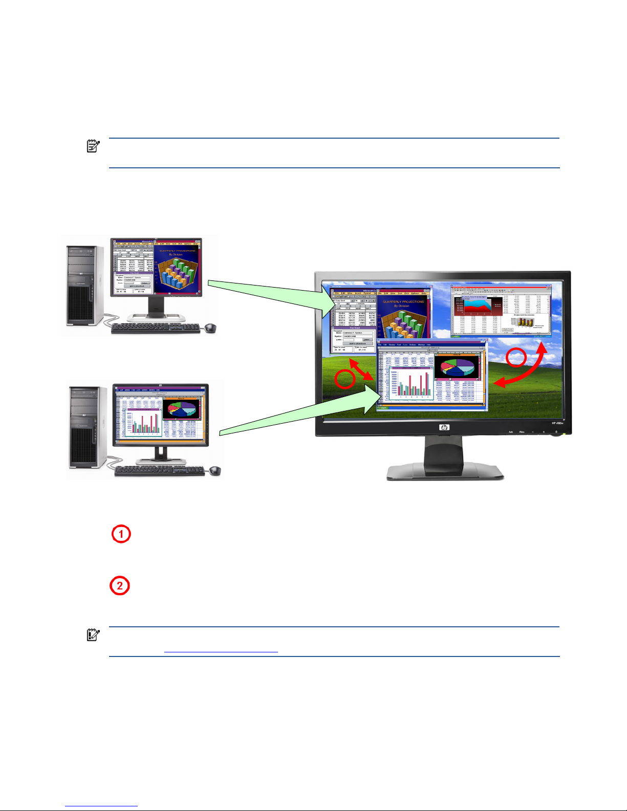
RGS overview 42
2-18 Remote Clipboard overview
Remote Clipboard was originally supported with RGS 5.1.3, enabling the user to cut or copy data between a
window on the Local Computer (the Local Window) and a Remote Display Window (provided that both the
Remote and Local Computers are running Windows, and the applications being used support cut and paste, and
copy and paste. Beginning with RGS 5.3.0, Remote Clipboard cut and paste of ANSI text data is supported
between Microsoft Windows Receiver systems and Linux Sender systems.
NOTE: For simplicity, the phrase “cut and paste” is used subsequently to refer to both cut and paste as well as
copy and paste.
At RGS 5.2, support was added for cut and paste between two Remote Display Windows (see Figure 2-25).
Figure 2-25 Remote Clipboard operation
Cut and paste are supported in the following scenarios.
Between a Local Window and a Remote Display Window (in both directions)—The Remote Computer may
be running Windows or Linux. The Local Computer must be running Windows.
Between two Remote Display Windows (in both directions)—In this case, the Local Computer can be
running either Windows or Linux; the Remote Computers may be running Windows or Linux.
IMPORTANT: Not all data formats can be transferred using cut and paste between Windows applications. See
Section 6-6, “Remote Clipboard operation
,” for detailed information on the supported formats.
Remote Computer #1
Remote Computer #2
Remote Display
Window #1
Remote Display
Window #2
Local Computer
Local Window
1
2
Page 43

RGS overview 43
In order for Remote Clipboard to be usable, it must be enabled during both the Sender and Receiver installations
on Microsoft Windows (see Figure 2-26). See “Manual installation of the Receiver on Windows
” and “Manual
installation of the Sender on Windows” for further information on Remote Clipboard installation.
Figure 2-26 Enabling Remote Clipboard during Sender and Receiver installation on Microsoft Windows systems.
For details on using Remote Clipboard, see Section 6-6, “Remote Clipboard operation.”
Following installation, Remote Clipboard on Windows can be enabled or disabled via a toggle in the Receiver's
controls.
Page 44

RGS overview 44
2-19 Interoperability of RGS and Microsoft Remote Desktop
Connection
This section discusses interoperability considerations for RGS and Microsoft Remote Desktop Connection (RDC).
Because RGS and RDC both provide connection to a remote desktop, their interoperation is important to
understand.
If a local user is connected to a Remote Computer using RDC, and then attempts to establish an RGS connection,
the RGS connection only works if the local user credentials match for both connections. This implies that the same
user wants access to transition from RDC to an RGS connection. If the credentials match, the current RDC session
disconnects, and the RGS Receiver takes control of the Remote Computer Windows desktop session. The current
user does not log off, and work continues with the new connection.
The reverse works as well. If a user is connected with RGS, and then connects with RDC (using the same
credentials as the RGS connection), the RDC connection displaces the RGS connection. In this case, the RGS
Sender will disconnect all Receivers (including all RGS collaborators). The Windows desktop session remains
active during the switch.
If an RDC user disconnects from a Remote Computer using the RDC disconnect button, the session remains logged
in, and all applications continue to run. The session, however, locks its screen. An RGS connection works only if
the credentials match the currently logged-in user.
If a user logs out of their session while using RDC, the RGS Sender returns the system to its initial logged out state.
Any authorized user can connect and log into this system using RGS.
An RDC connection made to a Sender already occupied with a RGS connection by a non-matching user prompts
the new user to logout the current RGS user. Only administrators can log out other users. Non-administrators are
refused with a warning message about permissions. If RDC logs out the current RGS user, then the Sender
disconnects all of its receivers (including all RGS collaborators).
Under reverse circumstances for the above, RGS connections will not log out an existing RDC user, regardless of
authority. RGS will report an authorization failure message concerning a different user owning the desktop
2-20 Using RGS with desktop virtualization
In addition to using RGS to capture, compress, and transmit the contents of the frame buffer, RGS can also be
used in a desktop virtualization environment to capture, compress, and transmit the contents of a virtual frame
buffer. A virtual frame buffer is a segment of system memory that is used to store the desktop image to be
displayed. HP’s Virtual Desktop Infrastructure (VDI) solution allows multiple user desktop sessions to run as
separate virtual machines, while sharing the underlying physical hardware resources such as CPU, memory,
networking, and storage. For information on VDI, visit www.hp.com/go/vdi
.
For information on installing and using RGS in the VDI environment, see Appendix A: Using RGS with HP VDI
.
.
Page 45

RGS overview 45
2-21 Remote Computer power saving states
In order for a Local Computer to establish connection to a Remote Computer, the Remote Computer cannot be in a
power saving state, such as Windows hibernate or standby. Furthermore, the Remote Computer cannot utilize
wake-on-LAN in an attempt to power-up in order to respond to a connection request from the Local Computer—the
Remote Computer must be powered-up, and able to respond to an RGS connection request at all times.
2-22 Supported keyboard locales
The following keyboard localizations are supported when connected to a Linux Sender:
1. French
2. German
3. Japanese
4. Norwegian
5. Swedish
6. United Kingdom
7. U.S. English
The following keyboard localizations are supported when connected to a Windows Sender:
1. Belgian French
2. Canadian French
3. Chinese (Simplified) – US Keyboard
4. Chinese (Traditional) – US Keyboard
5. Czech
6. Czech (QWERTY)
7. Danish
8. Dutch
9. Finnish
10. French
11. German
12. Italian
13. Japanese
14. Korean
15. Latin American
16. Norwegian
17. Portuguese
18. Portuguese (Brazilian ABNT)
19. Russian
20. Spanish
21. Swedish
22. Swiss French
23. Swiss German
24. Turkish Q
25. United Kingdom
26.
United Kingdom Extended
27. United States-In
ternational
28. US
Page 46

RGS overview 46
2-23 RGS security features
Because of the distributed nature of an RGS connection, providing connection security is critically important. RGS
implements many features to provide connection security, including:
• Authentication: When a local user attempts to connect to a Remote Computer, the user credentials are
validated using the native authentication method on the Remote Computer. If the credentials are not
authenticated, the connection is closed. On Windows, authentication uses NTLM or Kerberos. On Linux,
authentication uses the Pluggable Authentication Module (PAM).
• Authorization: Multiple connections to the same Remote Computer are only allowed if the user logged into
the desktop of the Remote Computer (primary user) allows the connection. When another user attempts to
connect to the Remote Computer, an authorization dialog is displayed on the desktop of the Remote
Computer that asks whether the new user should be allowed to connect.
• Automatic desktop locking: The desktop of the Sender system locks when the primary user disconnects. This
prevents non-primary users from being able to interact with a remote session after the primary user has
disconnected. This feature is supported on Windows. On Linux, this feature is supported on the Gnome,
KDE, and CDE desktop environments.
• Automatic disconnect: On Linux, all Receivers will disconnect when the primary user disconnects. This
prevents non-primary users from interaction with a remote session after the primary user disconnects.
• Automatic disconnect of non-primary users on Login: All non-primary users are disconnected when a login
event occurs. Only the primary user remains connected when the desktop of the remote computer is logged
in.
• Automatic disconnect on log off: All Receivers are disconnected when the primary user logs off of the remote
desktop. This can be disabled by setting the Rgsender.IsDisconnectOnLogoutEnabled Sender
property to "0". See the Sender properties for more information.
• Connection status: On Windows, a desktop icon in the application tray animates when other users are
connected. Likewise, on Linux, the Sender GUI animates.
• Collaboration notification: See Section 5-5-2, “Collaboration notification
.”
• Connections are not allowed when an iLO remote console is enabled: If the iLO remote console is enabled on
a HP Blade Workstation, connections to the blade using RGS are denied.
• Disconnect all: All Receivers can be easily disconnected using the Sender GUI. This is useful when hosting a
collaboration session, such as in a classroom environment, and the session ends. On Windows, the Sender
GUI is an icon in the system tray. On Linux systems, the GUI is an application on the desktop. Simply rightclick on the GUI and select "Disconnect All Receivers".
• Remote Keyboard/Mouse: The Sender GUI can enable or disable mouse and keyboard input for all non-
primary users.
• Single user connection: A user, identified by a username, is only allowed one connection to a RGS Sender. If
the same username connects more than once to a Sender, the previous connection drops and the new
connection continues on. If several users attempt to share a username, only one connection is active at a
time.
• SSL encryption: SSL securely encrypts all data transmitted between a Receiver and Sender pair.
Page 47

Installing RGS 47
3 Installing RGS
This chapter describes the following aspects of installing RGS:
• Installing the RGS Receiver on Windows
• Installing the RGS Sender on Windows
• Installing the RGS Receiver on Linux
• Installing the RGS Sender on Linux
IMPORTANT: RGS licensing applies to the RGS Sender only. The RGS Receiver is a free download and can be used
on any number of computers. Licensing of the RGS Sender on Windows and Linux is described in the HP Remote
Graphics Software Licensing Guide, available at www.hp.com/support/rgs_manuals. Note that Sender licensing is
checked when an RGS connection is established; therefore, the licensing mechanism has no affect on downloading
the RGS product, and installing the RGS Sender.
However, as described in Section 2-3, “RGS licensing
,” installing the RGS Sender without a valid license will result in
an error dialog being displayed in the Remote Display Window. Therefore, before downloading a new RGS version,
and installing a new RGS Sender, ensure that your RGS license entitles you to use the new RGS Sender version.
Again, refer to the HP Remote Graphics Software Licensing Guide at www.hp.com/support/rgs_manuals
for
detailed information.
NOTE: The RGS Sender is configured to start when the Sender computer boots (or, in the case of Linux, also when
the X server starts.
The RGS Receiver can be started from a command line. However, because the Receiver can also be started from the
start menu (on Windows), both methods of starting the Receiver (on a command line and using the start menu) are
described together, in Section 5-1, “Using RGS in Normal Mode
.”
3-1 Installing RGS on Windows
This section describes installation of the RGS Receiver and Sender on Windows. See Figure 2-1 for a list of the
Windows operating systems that support the RGS Receiver and Sender.
3-1-1 Installing the Receiver on Windows
This section describes manual and automatic installation of the RGS Receiver on Windows.
Manual installation of the Receiver on Windows
To install the Receiver on Windows, log into an account with administrator privileges, and perform the following
steps:
1. Go to the directory where you downloaded RGS, and change to the directory win32\receiver.
2. Double-click Setup.exe to start the Receiver installation, and follow the instructions on the screen.
Page 48

Installing RGS 48
3. During the installation, the Remote USB Configuration dialog is displayed (see Figure 3-1 and Section 2-16,
“Remote USB overview
”). Additional information can be viewed by selecting I’m not sure, I want more
information, and clicking Next. Select the USB configuration option that meets your needs, and click Next.
Figure 3-1 Receiver Remote USB configuration dialog
NOTE: For many USB devices, the Windows operating system provides default USB drivers. While these
default drivers may, in fact, work with your USB devices, it is recommended that you install the manufacturersupplied USB drivers to optimize functionality and performance of your USB devices. The manufacturersupplied driver should be installed on the computer, Local or Remote, where the USB devices will be logically
(not physically) attached.
4. The Remote Clipboard Configuration dialog is displayed next (see Figure 3-2 and Section 2-18, “Remote
Clipboard Overview”). Additional information can be viewed by selecting I’m not sure, I want more
information, and clicking Next. Select the desired Remote Clipboard Configuration option, and click Next.
Figure 3-2 Remote Clipboard Configuration dialog
Page 49

Installing RGS 49
NOTE: Selecting “Yes” will cause the hprclipboard.dll library to be installed with the RGS Receiver. If
you select “No”, this DLL won’t be installed and you won’t be able to use Remote Clipboard. To enable Remote
Clipboard later, you would need to reinstall the RGS Receiver, and select “Yes” in the above dialog.
5. The final installation step will normally prompt you to restart your computer.
Automatic installation of the RGS Receiver on Windows
The RGS Receiver can be installed or removed in automatic mode. Automatic mode allows the Receiver to be
installed or removed without any user interaction. Automatic mode will also restart the computer, if required, after
the installation process completes.
Should an illegal combination of command line options be specified, or if an error occurs during the install
process, the install will abort and the error will be logged to the Receiver installation log file.
Usage
Setup.exe /autoinstall /agreetolicense [/folder=<folder>]
[/usb=local | /usb=remote | /usb=localRemote]
[/clipboard]
[/noreboot]
[/removesettings]
Setup.exe /autoremove [/noreboot]
Setup.exe /viewlicense
Setup.exe /help
Command line options
/autoinstall
This option performs one of the following:
• Installs the Receiver if it's not already installed.
• Updates the Receiver if a prior version of the Receiver is already installed.
• Repairs the Receiver if the version being installed is the same as the version that is already installed.
The Receiver will not be reinstalled if the version of the Receiver being installed is older than the version of the
Receiver already installed.
/agreetolicense
Use of this option indicates that the user agrees to the license for use of this software. This option is required when
doing an install.
/autoremove
Remove the Receiver.
/folder=<folder>
Specifies the destination folder, default is C:\Program Files\Hewlett-Packard\Remote Graphics Receiver.
/usb=local
Install USB in Local Mode.
/usb=remote
Install USB in Remote Mode. The system will automatically restart after the install completes.
/usb=localRemote
Install USB in Local/Remote Mode. The system will automatically restart after the install completes. This is the
default if none of /usb=local, /usb=remote, and /usb=localRemote are specified.
/clipboard
Enable remote clipboard.
/noreboot
Do not reboot the system when the setup requires a reboot to complete.
/removesettings
Page 50

Installing RGS 50
Removes the user specific Receiver settings from the registry.
/viewlicense
Displays the EULA (End User License Agreement) for use of this software.
/help
Display usage text.
Page 51

Installing RGS 51
Receiver installation log file
Installation of the Receiver creates an installation log file. This log file can be viewed by the user to obtain details
about what operations were performed, and view any errors that occurred during the installation process. When
Setup.exe for the RGS Receiver is run, the following log file is created:
C:\TEMP\rgreceiverInstaller.log
The log file is especially useful for automatic installs because installer errors are not displayed on the screen, and
are only viewable using the log file. If the log file already exists when the installer is run, the installer will remove
the current contents of the log file before writing to it. This prevents the log file from growing without bounds.
Uninstalling the RGS Receiver on Windows
To uninstall the RGS Receiver, use the Windows Add or Remove Programs feature from the Control Panel. Select
Remote Graphics Receiver, and click Change/Remove. A dialog box will open with choices for: Repair or
Remove. Choose Remove to uninstall the RGS Receiver. On certain client computers simply re-run the
setup.exe program that you used to originally install the Receiver in place of using the Windows Add or
Remove Programs feature.
IMPORTANT: After the Receiver is uninstalled, you may be prompted to restart your computer. This restart is
very important—if it’s not performed, installation of a later version of the RGS Receiver may not succeed.
Page 52

Installing RGS 52
3-1-2 Installing the Sender on Windows
IMPORTANT: The Sender can only be installed on the computers and operating systems shown in Figure 2-1.
Installing the Sender on a non-supported computer will prevent an RGS connection from being established.
This section covers the following topics:
• Manual installation of the Sender on Windows
• The Sender diagnostics tool, rgdiag.exe
• Starting the Sender on Windows
• The Sender GUI
• Manually starting and stopping the Sender
• Automatic installation of the RGS Sender on Windows
NOTE: Starting with RGS 5.1.3, installation of the Sender on Windows may be performed remotely using
Microsoft Remote Desktop Connection.
Manual installation of the Sender on Windows
To install the Sender on Windows, log into an account with administrator privileges, and perform the following
steps:
1. Go to the directory where you downloaded RGS, and change to the directory win32\sender.
2. Double-click Setup.exe to start the Sender installation, and follow the instructions on the screen.
3. During the installation, the Remote Graphics Sender Configuration dialog is displayed (see Figure 3-3).
Chec
k the boxes appropriate to your requirements, as follows:
a. Enable Remote USB—Check this box if USB devices attached to the Local Computer need to be
accessible by the Remote Computer. For further information, see Section 2-16, “Remote USB overview.”
b. Enable Remote Microphone—Check this box to enable remote microphone. Remote microphone is not
supported on Microsoft Windows Vista therefore; this option is not available on Windows Vista. For
further information, see Section 2-17, “Remote audio overview.”
c. Enable Remote Clipboard—Check this box if your Local Users will need Remote Clipboard capability.
For further information, see Section 2-18, “Remote Clipboard overview
.”
d. I’m not sure, I want more information—For further information, check this box, and click Next.
Figure 3-3 Dialog to enable or disable Remote USB in the Sender
Page 53

Installing RGS 53
NOTE: For many USB devices, the Windows operating system provides default USB drivers. While these
default drivers may, in fact, work with your USB devices, it is recommended that you install the manufacturersupplied USB drivers to optimize functionality and performance of your USB devices. The manufacturersupplied USB driver should be installed on any computer, Local or Remote, where the USB devices will be
logically (not necessarily physically) attached.
4. Next you’ll be presented with a dialog to enable either Single Sign-On or Easy Login (see Figure 3-5). If
you’re not sure, you will be able to configure them later using the rgadmin.exe tool.
Figure 3-4 Dialog to enable Single Sign-On or Easy Login
5. Next, the Sender installer will prompt you for the Sender license (see Figure 3-5). If you have a Sender
license file, click the appropriate radio button, click Next, and provide the requested information. If you
don’t yet have a license file, click I do not yet have a license file and click Next. You can install your license
file later.
Figure 3-5 Configuration of the RGS Sender license
IMPORTANT: Absent a license file, the RGS Sender will still function correctly, and you’ll be able to establish a
connection from the RGS Receiver. However, the dialog shown in Figure 2-3 will be displayed in the Remote
Disp
lay Window. Installation of the license file is described in detail in the HP Remote Graphics Software
Licensing Guide, available at www.hp.com/support/rgs_manuals
.
Page 54
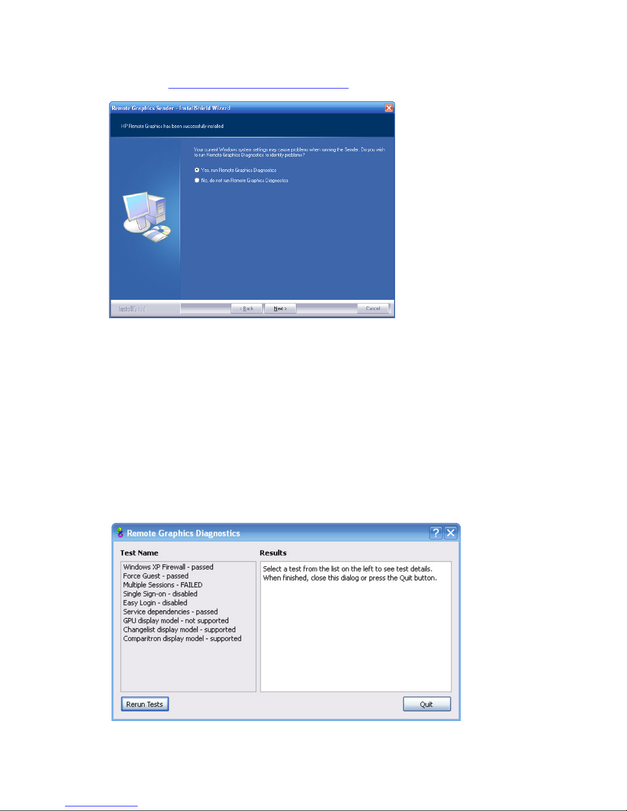
Installing RGS 54
6. Next, the Sender installer will run the rgdiag.exe diagnostics tool. If the tool detects a problem, the
dialog shown in Figure 3-6 is displayed. This dialog allows you to run rgdi
ag.exe directly—refer to the
Section “Using the RGS Diagnostics Tool on Windows
” for information about using this tool.
Figure 3-6 Diagnostics prompt dialog
7. You will be prompted to restart your computer after the Sender installation is complete. Select yes when
asked to restart the system.
Using the RGS Diagnostics Tool on Windows
After completion of a normal installation of the Windows Sender, the RGS Diagnostics Tool (rgdiag.exe)
automatically runs to detect potential issues (such as Windows firewall settings, Guest Account security policies,
RDP interoperability, and Easy Login settings) that might prevent a remote connection. If the tool detects a
problem, the dialog of Figure 3-6 is displayed, allowing you to run the
tool manually. Figure 3-7 shows the output
generated by the tool.
Figure 3-7 Output of the RGS Diagnostics Tool
The Test Name left panel shows the list of tests that have been run. Selecting a test with the mouse will display
additional information in the Results right panel. The Rerun Tests button on the bottom left reruns all tests. The
example window shows that all tests have passed with the exception of the Multiple Sessions test. To determine
Page 55

Installing RGS 55
what this test looked for, why it failed, whether this failure would prevent connections, and how to fix the problem,
click on the Multiple Sessions test title to display its details in the Results panel.
The RGS Diagnostics Tool can be run any time after RGS Sender installation. To run the Diagnostics Tool, use
Windows Explorer to display the RGS Sender installation folder, and locate the rgdiag.exe program with the
RGS icon. On a 32-bit Windows system, this tool is normally located at:
C:\Program Files\Hewlett-Packard\Remote Graphics Sender\rgdiag.exe
Note that the rgdiag.exe tool does not run as part of an unattended install.
Starting the Sender on Windows
The Windows Sender is comprised of two processes, one of which runs as a Windows Service. When the Remote
Computer boots, the installed services are typically started. The service process, rgsendersvc.exe will then start the
RGS Sender process rgsender.exe. When the RGS Sender is installed, an entry is added in the Windows Registry
for the Remote Graphics Sender service,
The Windows Sender service can also be registered and unregistered with Windows via command line like:
rgsendersvc.exe /service – registers the RGS Sender service with Windows
rgsendersvc.exe /unregserver – unregisters the RGS Sender service with Windows.
rgsender.exe supports the following options passed to it via registry parameters to rgsendersvc.exe (see the
registry editing instructions below):
[-nocollab]
[-timeout value]
[-authtimeout value]
[-l logSetupFile]
[-v | -ver | -version]
[-h | -help | -?]
[-belownormal | -normal | -abovenormal | -high]
[-Rgsender.
propertyname=value]
The functionality of each option is as follows:
-nocollab—Disables collaboration. When specified, only the primary user can connect to the Sender.
-timeout value—The timeout in milliseconds used to detect and disconnect an inactive connection. This option
sets the property Rgsender.Network.Timeout.Error. See “Network timeouts
” for more details.
-authtimeout value—The timeout in milliseconds used to detect and notify the user of a network disruption.
This option sets the property Rgsender.Network.Timeout.Dialog. See “Network timeouts
” for more details.
-l logSetupFile—Specifies the "logSetupFile" file used to describe various logging parameters for Sender
error and informational output. This file is used to determine where the output goes (to a file or to standard error)
as well as the type of output logged (INFO or DEBUG). At installation, the Sender default is with "-l logSetup"
turned on, where the logSetup file in the installation directory is set for output to a file named rg.log at INFO
debug level.
[-v | -ver | -version]—Prints the Senders version information and is useful from a command window.
[-h | -help | -?]—Prints a listing of the various command line options, those that are listed on this page
and is useful from a command window.
-belownormal—Sets the process priority of the Sender to below normal.
-normal—Sets the process priority of the Sender to normal. This is the default priority.
-abovenormal—Sets the process priority of the Sender to above normal.
-high—Sets the process priority of the Sender to high.
Page 56

Installing RGS 56
-Rgsender.propertyname=value—Can be used to specify one or more RGS Sender properties. See Chapter
8, “RGS properties
,” for general information on RGS properties. For information specifically on RGS Sender
properties, see Section 8-6, “RGS Sender properties
.”
regedit can be used to modify the parameters that are used for starting the Sender by the Sender service as
follows:
1. Start regedit—This can be done by opening a Windows command prompt and executing the command
“regedit” or using the "run" command line from the Start menu.
2. Using regedit, navigate to the key:
HKEY_LOCAL_MACHINE\SYSTEM\CurrentControlSet\Services\rgsender
3. Add the desired process priority command-line option for starting the Remote Graphics Sender service. For
example, to increase the process priority to high add the “-high” option to the key “ImagePath” as follows:
"C:\Program Files\Hewlett-Packard\Remote Graphics Sender\rgsendersvc.exe" -l
logSetup –high
4. Restart the Sender service with the new option. This can be done using the Windows Service Control
Manager (see “Manually starting and stopping the Sender on Windows
”) or by re-starting the computer.
The Sender GUI on Windows
The Windows Sender displays the HP Remote Graphics Software icon in the application tray. On Windows,
the icon animates when Receivers are connected to the Sender. Right click on the icon to display the Sender GUI
(see Figure 3-8).
Figure 3-8 Sender GUI
The following options are provided by the Sender GUI:
• Remote Keyboard/Mouse > Enable or Disable—If Disable is selected, all local users are in view-only mode—
only the primary user can control the Remote Computer desktop using a keyboard and mouse. If Enable is
selected, all local users (and the primary user) can interact with the Remote Computer desktop.
• Disconnect > Non-Primary Users or All Users—Disconnects Receiver sessions for either non-primary users or
all users.
• Help—Displays the RGS Help system.
• About—Displays the RGS program information.
Manually starting and stopping the Sender on Windows
By default, the Sender installs one executable as a Windows Service. This is necessary to enable some features,
such as the ability to send CTRL-ALT-DEL key sequences, and also view locked screens. Additionally, installing
the Sender service executable as a service allows Windows to automatically start the Sender service process when
the computer is started.
You can control Windows Services by accessing the "Services" panel. The "Services" panel can be accessed from
the Windows "Control Panel" and selecting "Administrative Tools". Figure 3-9 shows the Administrative Tool
for
Services. The Remote Graphics Sender is highlighted. The status of the service is "Started", and the service is
configured to start up automatically. By right clicking on the Remote Graphics Sender service, the service can be
stopped, started, or resumed. Additionally, the properties of the service can be controlled such as the start-up
type, and the recovery mode.
Page 57

Installing RGS 57
Figure 3-9 The Remote Graphics Sender service
Setting the Windows Sender process priority
This section discusses adjusting the process priority of the Windows Sender. The default process priority of the
Windows Sender is normal. In some cases, increasing the process priority of the Sender will improve
interactivity—for example, when the Windows scheduling algorithms does not give the RGS Sender sufficient CPU
time to maintain smooth interactivity. Networking performance can also contribute to reduced interactivity.
The Windows Sender on some laptops has exhibited inconsistent performance. Increasing the Sender priority to
high usually improves interactivity in this case. This provides the Sender more frequent access to the CPU, and
improves the update frequency to the Receiver.
Process priority for the Sender is command line accessible for the Windows Sender. Four command-line options
are available:
–belownormal
-normal
-abovenormal
-high
Priorities low and realtime cannot be selected for the Windows Sender.
There are two ways to set the process priority of the Windows Sender:
• Use regedit to modify the rgsender service start up parameters in the Windows Registry. (see the regedit
instructions in the Starting the Sender on Windows
section)
• Use HP Performance Tuning Framework (PTF) to configure Windows Sender priority (available only on HP
Workstations)
CAUTION: Adjusting the process priority of the Sender to a level higher than –normal can cause other
normally-privileged processes to receive fewer CPU cycles than normal. Therefore, caution should be observed
in adjusting the priority of the Sender.
Setting the Sender process priority using PTF
The HP Performance Tuning Framework (PTF) can be used adjust the priority of the Sender without having to use
regedit. PTF is available for HP Workstations only from this location:
www.hp.com/workstations/software/framework/index.html
See the PTF help and documentation for further information.
Page 58

Installing RGS 58
Using the rgadmin tool
IMPORTANT: The rgadmin tool is only installed and supported on Windows XP.
This section describes use of the Sender rgadmin.exe tool. For a normal Sender installation, this tool can be
found at:
C:\Program Files\Hewlett-Packard\Remote Graphics Sender\rgadmin.exe
When run, the rgadmin.exe program displays two tabs. The 3D Updates tab (see Figure 3-10) can be used to
enable automatic 3D updates from the application to the Sender. These updates inform the Sender what screen
rectangles have been changed by 3D applications.
Figure 3-10 3D Updates tab
IMPORTANT: RGS versions prior to RGS 4.0 required the manual placement of the RGS OpenGL32.dll
library into the application directory for each application. For RGS 4.0 and later, this library may cause
applications to fail on startup. Because automatic updates of OpenGL applications are now supported, the
OpenGL32.dll library is no longer required, and should be removed from any application directories where
it resides.
Page 59

Installing RGS 59
The GINA Setup tab on the rgadmin tool can be used to enable Single Sign-on and Easy Login (see Figure 3-11).
When rgadmin is brought up, it reports the current status of Single Sign-on and Easy Login. To change the status,
check the desired radio button. After clicking Apply, you’ll be requested to restart your computer—this is required
in order for the new setting to take affect.
Figure 3-11 Dialog to enable or disable Single Sign-on and Easy Login
Page 60
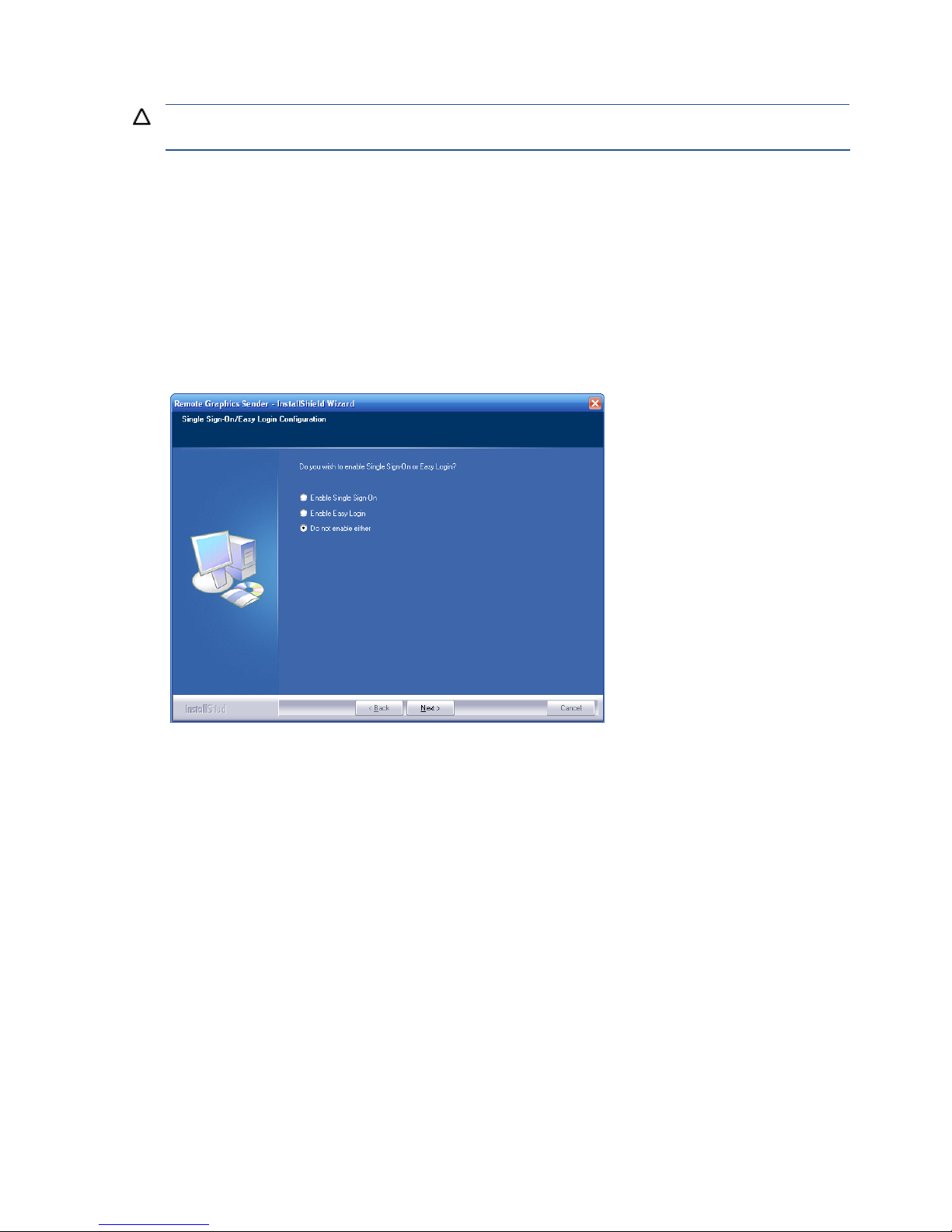
Installing RGS 60
Installing and enabling Single Sign-on
CAUTION: Installing RGS Single Sign-on is for experienced users and IT administrators only. Please read all
directions completely before proceeding, and exercise caution when installing.
Single Sign-on is only supported on HP blade workstations running the RGS Sender. The RGS shared library,
hprgina.dll, enables Single Sign-on. The file hprgina.dll is a GINA (Graphical Identification and
Authentication) module that is loaded by the Windows WinLogon.exe process. There are three ways to install
hprgina.dll, and therefore enable RGS Single Sign-on:
1. Enabling Single Sign-on during installation
Single Sign-on can be enabled during RGS Sender installation—enabling Single Sign-on installs the
hprgina.dll module. This is the preferred method to enable Single Sign-on. The default during installation is to
not enable Single Sign-on. The administrator must answer two questions to enable Single Sign-on (see Figure
3-12). If Single Sign-on is enabled, the computer must be restarted before Single Sign-on is operational.
Figure 3-12 The dialog presented during Sender installation to enable Single Sign-on or Easy Login
Page 61
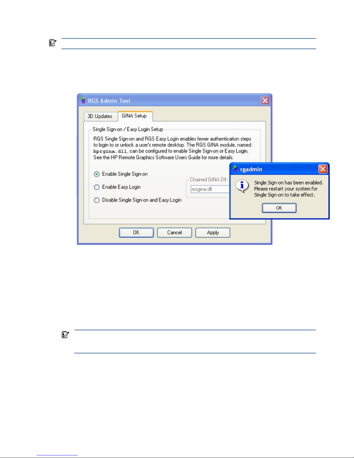
Installing RGS 61
2. Using the rgadmin tool to enable Single Sign-on
IMPORTANT: The rgadmin tool is only installed and supported on Windows XP.
The rgadmin tool can be used to enable Single Sign-on—check the Enable Single Sign-on radio button in Figure
3-13, and click Apply. Enabling Single Sign-on installs the hprgina.dll module. Using the rgadmin tool to
enable Single Sign-on is preferred over the manual method, described next.
Figure 3-13 Using the rgadmin tool to enable Single Sign-on
3. Manually enabling Single Sign-on
Although the manual method is not the preferred method to enable Single Sign-on, it is provided so that
administrators will know exactly what parts of the operating system are being modified. To manually enable
Single Sign-on, perform the following steps:
1. Install the Sender on the HP workstation. If the RGS Sender is not installed or installs with errors, do not
perform the remaining steps. Doing so will put the computer in a state that requires a complete re-installation
of the operating system.
2. After the RGS Sender is installed, confirm that hprgina.dll exists in the C:\WINDOWS\system32
directory. The Sender installer copies hprgina.dll directly into the system32 directory.
IMPORTANT: If the hprgina.dll does not exist in C:\WINDOWS\system32, do not perform the
remaining steps. Doing so will put the system in a state that requires a complete re-installation of the
operating system.
3. Add the GinaDLL registry key if it does not already exist. If the GinaDLL key does not exist, Microsoft's
default GINA DLL (msgina.dll) is loaded by WinLogon. Adding the GinaDLL registry key, and setting its
value to hprgina.dll informs WinLogon to load hprgina.dll instead of the default msgina.dll.
Adding the GinaDLL registry key is done using regedit, the Windows Registry Editor. Create the key as
type REG_SZ (a string type). The full path of the key is:
HKEY_LOCAL_MACHINE\Software\Microsoft\Windows NT\CurrentVersion\Winlogon\GinaDLL
Page 62

Installing RGS 62
4. Set the value of the GinaDLL key to the text "hprgina.dll". Confirm the spelling before closing. Figure
3-14 shows the registry key contents.
Figure 3-14 Addition of the GinaDLL key to the registry
5. Add the GinaDllMode registry key if does not already exist. This can be done through the use of regedit
as well. Create the key as type RGS_SZ (a string type). The full path of the key is:
HKEY_LOCAL_MACHINE\Software\Hewlett-Packard\Remote Graphics Sender\GinaDllMode
6. To actually enable Single Sign-on, set the value of the GinaDllMode key to the text "HprSso". Confirm the
spelling before closing. Figure 3-15 shows the registry key contents.
Figure 3-15 Addition of the GinaDllMode key to the registry
7. Restart the computer. The hprgina.dll module will be loaded by WinLogon when started.
Summary—If the GinaDLL key does not currently exist in the registry, Microsoft's default GINA DLL
(msgina.dll) is loaded by WinLogon. Adding the GinaDLL registry key, and setting its value to
hprgina.dll, informs WinLogon to load hprgina.dll instead of the default msgina.dll.
Setting the local security policy
The local security policy "Interactive logon: Do not require CTRL-ALT-DEL" must be disabled to support Single Signon. This can be set in the Windows "Local Security Settings" under "Security Options." The RGS Diagnostics Tool
programmatically detects if this local security policy is set correctly. See the section “Using the RGS Diagnostics
Tool on Windows” for information on this tool.
NOTE: Creating the GinaDLL registry key disables Window's "Fast User Switching" and "Welcome Screen"
features.
Disabling Single Sign-on
There are two methods to disable Single Sign-on:
1. Using the rgadmin tool to disable Single Sign-on
The rgadmin tool shown in Figure 3-13 can be used to disable Single Sign-on. Using the rgadmin tool to
disable Single Sign-on is preferred over the manual method, described next.
2. Manually disabling Single Sign-on
To disable Single Sign-on without using the rgadmin tool, delete or rename the value of the GinaDLL registry
key. If there is no other custom GINA module on the computer, simply removing the GinaDLL key definition from
the registry entry below disables Single Sign-on.
HKEY_LOCAL_MACHINE\Software\Microsoft\Windows NT\CurrentVersion\Winlogon\GinaDLL
The GinaDLL key is removed using regedit, the Windows Registry Editor. Be sure to actually remove the key by
selecting the GinaDLL key in regedit, and select the Delete entry in the Edit menu. Once the key is
CAUTION: If the value of the GinaDLL key contains the name of a custom GINA DLL, and the file does not
exist in C:\WINDOWS\system32, the computer will not start correctly after the next reboot. The computer will
then require a complete re-installation of the operating system.
Page 63

Installing RGS 63
deleted, it will no longer show up as a key in the WinLogon subkey. When the system reboots, the default GINA
module, msgina.dll, will be loaded by the WinLogon.exe process.
If there is a custom GINA DLL module on the system, and if it replaces the default msgina.dll, change the value
of the GinaDLL value from hprgina.dll to the name of the custom GINA module. To change the value of the
GinaDLL key, select the GinaDLL key in regedit, and then select the Modify entry in the Edit menu. A
dialog box appears allowing the value of the key to be changed. Type the name of the custom GINA module in
the "Value data:" area. Confirm that the custom GINA module entered actually exists in
C:\WINDOWS\system32. When the computer restarts, the custom GINA module will be loaded by the
WinLogon.exe process.
Installing and Enabling Easy Login
CAUTION: Installing RGS Easy Login is for experienced users and IT administrators only. Please read all
directions completely before proceeding, and exercise caution when installing.
Easy Login is only supported on HP blade workstations running the RGS Sender. The RGS shared library,
hprgina.dll, enables Easy Login. The file hprgina.dll is a GINA (Graphical Identification and
Authentication) module that is loaded by the Window WinLogon.exe process. There are three ways to install
hprgina.dll, and therefore enable RGS Easy Login on the Sender:
1. Enabling Easy Login during installation
Easy Login can be enabled during RGS Sender installation—enabling Easy Login installs the hprgina.dll
module. This is the preferred method to enable Easy Login. The default during installation is to not enable Easy
Login. The user must answer two questions to enable Easy Login, as shown in Figure 3-12. If Easy Login is
enabled, the computer must be restarted before Easy Login is operational.
2. Using the rgadmin tool to enable Easy Login
The rgadmin tool can be used to enable Easy Login— check the Enable Easy Login radio button as shown in
Figure 3-11, and click Apply. Enabling Easy Login installs the hprgina.dll module. Using the rgadmin tool to
enable Easy Logon is preferred over the manual method, described next.
3. Manually enabling Easy Login
Although the manual method is not the preferred method to enable Easy Login, it is provided so that administrators
will know exactly what parts of the operating system are being modified. To manually enable WinLogon to load
the hprgina.dll module, perform the following steps:
1. Install the Sender on the HP workstation. If the RGS Sender is not installed or installs with errors, do not
perform the remaining steps. Doing so will put the computer in a state that requires a complete re-installation
of the operating system.
2. After the RGS Sender is installed, confirm that hprgina.dll exists in the C:\WINDOWS\system32
directory. The Sender installer copies hprgina.dll directly into the system32 directory.
IMPORTANT: If the hprgina.dll does not exist in C:\WINDOWS\system32, do not perform the
remaining steps. Doing so will put the system in a state that requires a complete re-installation of the
operating system.
3. Add the GinaDLL registry key if it does not already exist. This can be done through the use of regedit,
the Windows Registry Editor. Create the key as type REG_SZ (a string type). The full path of the key is:
HKEY_LOCAL_MACHINE\Software\Microsoft\Windows NT\CurrentVersion\Winlogon\GinaDLL
4. Set the value of the GinaDLL key to the text "hprgina.dll" as shown in Figure 3-14. Confirm the
spelling before closing.
5. Add the GinaDllMode registr
y key if does not already exist. This can be done through the use of regedit
as well. Create the key as type RGS_SZ (a string type). The full path of the key is:
HKEY_LOCAL_MACHINE\Software\Hewlett-Packard\Remote Graphics Sender\GinaDllMode
Page 64

Installing RGS 64
6. To actually enable Easy Login, set the value of the GinaDllMode key to the text "HprEasyLogin".
Confirm the spelling before closing. Figure 3-16 shows the registry key contents:
Figure 3-16 Addition of the
GinaDllMode key to the registry
7. Restart the computer. The hprgina.dll module will be loaded by WinLogon when started.
Summary—If the GinaDLL key does not currently exist in the registry, Microsoft's default GINA DLL
(msgina.dll) is loaded by WinLogon. Adding the GinaDLL registry key, and setting its value to
hprgina.dll, informs WinLogon to load the hprgina.dll instead of the default msgina.dll.
The hprgina module is a chaining GINA DLL. When the RGS hprgina.dll is loaded by WinLogon, the
hprgina module loads the msgina.dll shared library. The hprgina module chains (forwards) all GINA
requests to the msgina.dll module.
Chaining custom GINA modules for Easy Login
If it is determined in step 3 above that the GinaDLL registry key does exist, and the value of the key is not
msgina.dll, then a custom GINA module is currently loaded and being used by WinLogon. Custom GINA
modules provide custom authentication dialogs or even custom user authentication methods. If it is determined that
functionality of both the RGS Easy Login and a custom GINA module is required, the hprgina.dll needs further
configuration. The hprgina.dll module needs to be set up to load the custom GINA module rather than the
default msgina.dll as described above. There are three ways to enable the hprgina.dll module to load a
custom GINA module:
1. Install time specification of the custom GINA module
A custom GINA module can be chained by the hprgina.dll at install time. This is the preferred method. The
installer will bring up a GUI that allows the Easy Login GINA module (hprgina.dll) to be enabled, as well as
provides a text box to enter the name of the custom GINA module. The name of the custom module is all that is
needed, provided it is installed in the C:\WINDOWS\system32 directory. If the custom module is installed
elsewhere, the full file path needs to be entered.
2. Using the rgadmin tool to specify a custom GINA module
The rgadmin tool can be used to chain a custom GINA module. When Enable Easy Login is selected, the
associated text entry box Chained GINA Dll is un-greyed out. Enter the name of the custom GINA module in the
text box, and click Apply. Using the rgadmin tool to specify a custom GINA module is preferred over the manual
method, described next.
3. Manually enabling hprgina.dll to load a custom GINA module
To manually enable the hprgina.dll module to load a custom GINA module, create a new registry key,
ChainedGinaDLL, with the value of the key containing the name of the chained custom GINA module. Perform
steps 1–6 shown above (the restart will be done below) plus the following three steps to chain custom modules:
1. Create the ChainedGinaDLL registry key. Create the key as type REG_SZ (a string type). The full path of
the key is:
HKEY_LOCAL_MACHINE\Software\Hewlett-Packard\Remote Graphics Sender\ChainedGinaDLL
2. Set the value of the new ChainedGinaDLL key to the name of the custom GINA module. For example, if
the name of the custom GINA module is foogina.dll, then the value of the key should be
foogina.dll. The value should match the string originally discovered in the registry key GinaDLL.
Confirm the spelling before closing.
3. Restart the computer.
When the RGS hprgina.dll is loaded by WinLogon, hprgina.dll will load the chained GINA module
foogina.dll. The hprgina module then chains all GINA requests to the foogina.dll module.
If the custom foogina.dll is also a chaining GINA module, foogina.dll, in turn, chains itself to the
msgina.dll module. Three GINA DLLs will be loaded as part of the WinLogon.exe process: (1)
hprgina.dll, (2) foogina.dll, and (3) msgina.dll.
Page 65

Installing RGS 65
3-1-2-1 Setting the Local Security Policy
The local security policy "Interactive logon: Do not require CTRL-ALT-DEL" must be disabled to support Easy Login.
This can be set in the Windows "Local Security Settings" under "Security Options." The RGS Diagnostics Tool
programmatically detects if this local security policy is set correctly. See the section “Using the RGS Diagnostics
Tool on Windows“ for more information.
NOTE: Creating the GinaDLL registry key disables Window's "Fast User Switching" and "Welcome Screen"
features.
Disabling Easy Login
There are two methods to disable Easy Login:
1. Using the rgadmin tool to disable Easy Login
The rgadmin tool shown in Figure 3-11 can be used to disable Easy Login. Using the rgadmin tool to disable
Easy Login is preferred over the manual method, described next.
2. Manually disabling Easy Login
To disable Easy Login without using the rgadmin tool, delete or rename the value of the GinaDLL registry key. If
there is no other custom GINA module on the system, simply removing the GinaDLL key definition from the
registry entry below disables Easy Login.
HKEY_LOCAL_MACHINE\Software\Microsoft\Windows NT\CurrentVersion\Winlogon\GinaDll
The GinaDLL key is removed using regedit, the Windows Registry Editor. Be sure to actually remove the key by
selecting the GinaDLL key in regedit, and select the Delete entry in the Edit menu. Once the key is
deleted, it no longer shows up as a key in the WinLogon subkey. When the system reboots, the default GINA
module, msgina.dll, will be loaded by the WinLogon.exe process.
If there is a custom GINA DLL module on the system and it replaces the default msgina.dll, change the value of
the GinaDLL value from hprgina.dll to the name of the custom GINA module. To change the value of the
GinaDLL key, select the GinaDLL key in regedit, and then select the Modify entry in the Edit menu. A
dialog box appears allowing the value of the key to be changed. Type the name of the custom GINA module in
the "Value data:" area. Confirm that the custom GINA module entered actually exists on the system in
C:\WINDOWS\system32. When the system reboots the custom GINA module is loaded by the WinLogon.exe
process.
CAUTION: If the value of the GinaDLL key contains the name of a custom GINA DLL, and the file does not
exist in C:\WINDOWS\system32, the system will not start correctly upon the next reboot. The system will then
require a complete re-installation of the operating system.
Page 66

Installing RGS 66
Automatic installation of the RGS Sender on Windows
The RGS Sender can be installed or removed in automatic mode. Automatic mode allows the Sender to be
installed or removed without any user interaction. Automatic mode will also restart the computer, if required, after
the installation process completes.
Should an illegal combination of command line options be specified, or if an error occurs during the install
process, the install will abort and the error will be logged to the Sender installation log file.
Usage
Setup.exe /autoinstall /agreetolicense [/folder=<folder>]
[/usb]
[/remotemic]
[/clipboard]
[/sso | [/el [/gina=<filename>]]]
[/rgslicenseserver=<port@host> |
/rgslicensefile=<filename>]
[/noreboot]
[/removesettings]
Setup.exe /autoremove [/noreboot]
Setup.exe /viewlicense
Setup.exe /help
Command line options
/autoinstall
This option performs one of the following:
• Installs the Sender if it's not already installed.
• Updates the Sender if a prior version of the Sender is already installed.
• Repairs the Sender if the version being installed is the same as the version that is already installed.
The Sender will not be reinstalled if the version of the Sender being installed is older than the version of the
Sender already installed.
/agreetolicense
Use of this option indicates that the user agrees to the license for use of this software. This option is required when
doing an install.
/autoremove
Remove the sender.
/folder=<folder>
Specifies the destination folder, default is C:\Program Files\Hewlett-Packard\Remote Graphics Sender.
/usb
Enable remote USB.
/remotemic
Enable remote microphone.
/clipboard
Enable remote clipboard.
/sso
Enable Single Sign-on, only one of /sso and /el can be used.
/el
Enable Easy Login, only one of /sso and /el can be used.
/gina=<filename>
Chaining GINA module to use, default is "msgina.dll", can only be specified if /el is used.
/rgslicenseserver=<port@host>
The license to run the RGS Sender is acquired from a license server listening on the specified port and host. The
port/host must be in the form of port@host. The port and the trailing “@” are optional, in which case the default
port is used for the given host. Only one of /rgslicenseserver= or /rgslicensefile= may be specified.
Page 67

Installing RGS 67
/rgslicensefile=<filename>
The license to run the RGS Sender is acquired from the specified file. The filename may be omitted by specifying
the option as “/rgslicensefile=”, in which case the Sender will be installed without a license, and the
license file can be manually copied to the install folder at a later time. Only one of /rgslicenseserver= or
/rgslicensefile= may be specified. If neither /rgslicenseserver= or /rgslicensefile= are
specified, the install will proceed as if this option was specified without a filename.
/noreboot
Do not reboot the system when the setup requires a reboot to complete.
/removesettings
Removes the user specific Receiver settings from the registry.
/viewlicense
Displays the EULA (End User License Agreement) for use of this software.
/help
Display usage text.
Sender installation log file on Windows
As with installation of the Receiver, installation of the Sender also creates an installation log file. This log file can
be viewed by the user to obtain details about what operations were performed, and view any errors that occurred
during the installation process. When Setup.exe for the RGS Sender is run, the following log file is created:
C:\TEMP\rgsenderInstaller.log
The log file is especially useful for automatic installs because installer errors are not displayed on the screen, and
are only viewable using the log file. If the log file already exists when the installer is run, the installer will remove
the current contents of the log file before writing to it. This prevents the log file from growing without bounds.
Uninstalling the RGS Sender on Windows
To uninstall the RGS Sender, use the Windows Add or Remove Programs feature from the Control Panel. Select
Remote Graphics Sender, and click Change/Remove. A dialog box will open with choices for: Repair, Remove –
Retain User Settings, Remove – Delete User Settings. Retain User Settings will leave the user specific Sender
settings in the registry while Delete User Settings removes the user specific Sender settings from the registry.
IMPORTANT: After the Sender is uninstalled, you’ll be prompted to restart your computer. This restart is very
important—if it’s not performed, installation of a later version of the RGS Sender may not succeed.
Page 68

Installing RGS 68
3-2 Installing RGS on Linux
This section describes how to:
• Install and uninstall the RGS Receiver on Linux
• Install audio on the Linux Receiver
• Install and uninstall the RGS Sender on Linux.
IMPORTANT: Support of RGS on RHEL 5.2 (or later versions) requires that certain components be installed
during the installation of RHEL 5.2. During RHEL 5.2 installation, you’ll be presented with a dialog titled
Installation Number. When you see this dialog, enter the installation number provided with your acquisition of
RHEL 5.2. If the installation number is entered correctly, you’ll see the Software Development checkbox in the
screen following the root password prompt. Check this checkbox to ensure that the components required for
RGS operation are installed.
3-2-1 Installing the Receiver on Linux
NOTE: Beginning with RGS 5.1.3, the Linux RGS Receiver is available in both 32-bit and 64-bit versions.
To install the RGS Receiver on Linux, perform the following steps:
1. Login as root.
2. Go to the directory where you downloaded RGS, and change to the directory lin32/receiver (32-bit
version) or lin64/receiver (64-bit version).
3. Execute the following command:
./install.sh
NOTE: If remote audio is installed, RGS requires certain audio support utilities be available for remote
audio support from appropriate Senders. This software (based upon ALSA sound libraries and JACK-AudioConnection-Kit libraries) must be built and installed on the target system as a part of the install.sh script.
The install script assumes a supported set of ALSA sound libraries from HP or Red Hat Enterprise Linux
(release 4 or greater) already exist on the platform. Only the JACK-Audio-Connection-Kit is built during
install and it requires ALSA sound library support.
NOTE: The files contained within hp_rgs_4_audiosupport.tar.gz can also be built and configured for RPM
package creation. See script rgs_audio_support for details.
4. The Receiver will be installed into /opt/hpremote/rgreceiver. To start the Receiver, execute the
following command:
/opt/hpremote/rgreceiver/rgreceiver.sh
To start the Receiver in directory mode, execute the following command:
/opt/hpremote/rgreceiver/rgreceiver.sh -directory
5. Optionally, add the directory /opt/hpremote/rgreceiver to your PATH environment variable.
6. Refer to Section 3-2-3, “Installing audio on the Linux Receiver,” to complete the Receiver installation.
NOTE: Starting the Receiver on Linux is described further in Section 5-1, “Using RGS in Normal Mode.”
Page 69

Installing RGS 69
3-2-2 Uninstalling the Receiver on Linux
To uninstall the RGS Receiver on Linux find the name of the RedHat RPM package for the Remote Graphics
Receiver, by typing:
rpm -q -a | grep -i rgreceiver
If the Receiver is installed on the system, you will see rgreceiver_linux_32-5.1-0 or a similar Receiver
package. To remove the Receiver's RPM package, become root and type:
rpm -e --allmatches rgreceiver_linux_32
3-2-3 Installing audio on the Linux Receiver
If you install audio on the Linux Receiver, the audio component uses the JACK sound server API. JACK is a lowlatency sound server that works in conjunction with the ALSA sound drivers to mix and direct audio on your
system. It runs as a daemon in the background and acts as a “patch bay” for audio connections and applications
that use the JACK interface. Note that the ./install.sh command run in step 4 of the receiver install will build jack.
This section is only necessary if a custom build of alsa or jack is needed.
For reliable audio support with the Receiver for Linux, the bundled versions of the ALSA sound libraries and JACK
Audio Connection Kit software must be built and installed. Versions of ALSA prior to the version provided with the
installer may yield unsupportable results. Removal of these previous versions is advised prior to reinstallation of
ALSA software.
If multiple audio devices are installed in a system, administrators should identify the target audio system prior to
installing the included ALSA software. Properly configured kernel headers for the running kernel must be available
from the directory /lib/modules/<version>/build for proper installation. The example installation script
provided only builds/installs for the currently active kernel. The installation and configuration scripts require
administrator privileges on the target system. If you cannot become root on your system, ask an administrator for
assistance.
Once ALSA and JACK are installed and correctly configured, you are ready to use remote audio with the RGS
Receiver for Linux.
Audio Requirements
For reliable audio support with the Receiver for Linux, the bundled version of the JACK Audio Connection Kit
software must be built and installed. ALSA sound libraries must be HP-supported or Red Hat Enterprise Linux
(release 4 or greater) versions for best results. Manual installation of prior ALSA libraries may yield unpredictable
results on older releases of Linux. Do not mix versions of ALSA software. If multiple audio devices are installed in a
system, administrators should identify the target audio system prior to installing the included ALSA software.
Properly configured kernel headers for the running kernel must be available from the directory
/lib/modules/<version>/build for proper installation. The example installation script provided only
builds/installs for the currently active kernel. The installation and configuration scripts require administrator
privileges on the target system. If you cannot become root on your system, ask an administrator for assistance.
System Preparation
HP recommends that you remove all previously installed versions of JACK before installation. If the RPM package
manager was utilized, then the packages can be located by:
rpm -qa | grep -i jack
Removal by RPM involves utilizing the above search results with:
rpm -e --nodeps --allmatches {pkg-name}
The install script rgs_audio_support may detect residual directories from previous installations. Respond as
prompted during installation.
Customized Audio Installation
The following remote audio installation process for Linux is used when the RGS Receiver is installed through the
./install.sh script. For those installations that require customization or need to use other features from the
rgs_audio_support script, here are additional details for its use.
Page 70

Installing RGS 70
The audio support bundle ships as hp_rgs_4_audiosupport.tar.gz. It is accessed by the RGS
install.sh script in /opt/hpremote or may be utilized for manual installations / RPM package building.
The install process requires a locally writable directory in which to build. Locate the support bundle in an
appropriate directory before installation. Use the following command to unpack the file manually if desired:
tar xzf hp_rgs_4_audiosupport.tar.gz
As the user root, change directory into the one created by the command above. It will contain important files such
as:
README.txt
— basic instructions and file manifest
rgs_audio_support — shell installation script for ALSA/JACK libraries
alsa-*.tar.bz2 — recently validated tar archives from the ALSA project (provided only for open source
requirements and legacy installations) — see http://alsa-project.org
jack-*.tar.gz — recently validated tar archives from the JACK-Audio-Connection-Kit project — see
http://jackit.sourceforge.net
libsndfile-*.tar.gz — recently validated tar archives from the libsndfile project (JACK dependency) —
see http://www.mega-nerd.com/libsndfile
The sample installation script, rgs_audio_support, offers three installation scenarios:
• install — This command unpacks all tar archives into a local build directory in the current directory
[./localroot ], configures, builds, and installs the required ALSA/JACK libraries appropriate for the host
system and active kernel. It is a good choice for local installations or system development. A system reboot is
recommended for best results.
• remove — This command removes and unconfigures an installation provided by the above install
command.
• build_rpms — This command runs an install command first, and then attempts to create a compatible set
of binary RPMs for installation on matched system configurations. This will greatly reduce the work of
enterprise administrators duplicating this install process across multiple nodes. After a successful build, the
following files are created:
./RPMS/*.rpms — binary RPMs copied from /usr/src/redhat/RPMS
./RPMS/RGS_audio_install.sh — customized install and configuration script to associate
with RPMs
NOTE: The build log created by this script is located in /var/log/hpaudio.log
NOTE: The sample installation script, rgs_audio_support, supports limited customization capabilities for newer source
deliveries as they become available. See the script internals for more details.
Page 71

Installing RGS 71
3-2-4 Installing the Sender on Linux
IMPORTANT: The Linux RGS Sender can only be installed on the computers and Linux operating systems
shown in Figure 2-1. Installing the Sender on a non-supported computer will prevent an RGS connection from
being established.
Like the Windows RGS Sender, the Linux RGS Sender also requires a License Key in order to establish an RGS
connection. For information on RGS Sender licensing on Linux, see the HP Remote Graphics Software Licensing
Guide, available at www.hp.com/support/rgs_manuals
.
To install the Sender on Linux, perform the following steps:
1. Log in as root.
2. Go to the directory where you downloaded RGS, and change to the directory lin64/sender.
3. Execute the following command:
./install.sh
This command will give you a choice of performing a manual installation or a partially automated
installation (automating steps 5 and 6). The RGS Sender will be installed to /opt/hpremote/rgsender.
4. This last step of the install is optional, and will ask if you would like to automatically customize the following
files to enable proper function of the Linux Sender:
a. /etc/X11/XF86Config or /etc/X11/xorg.conf—The configuration file for the preferred X server
will be modified to load the rge extension in the “Modules” section. If a different X server configuration
is used, that file must be manually configured to load the rge module.
b. /etc/pam.d/rgsender—This configuration file will be modified to allow the Sender to interact with
the currently supported PAM authentication.
c. /etc/pam.d/gdm*, /etc/pam.d/kdm*, /etc/pam.d/xdm*—These configuration files will be
modified to ensure proper PAM authentication window manager support for the sender process. If a
different window manager is in use, that file must be manually configured.
The rgsender_config_64-*.rpm provides an automated way to handle the standard customizations described
below. This is especially useful for network or unattended installations requiring default PAM authentication
settings. The rpm can also be run independently of the install script.
NOTE: This automated step must be performed after any actions that install their own X server
configuration files because, in step (a) above, these files are modified to load the rge module required for
proper Sender functionality. If these files are replaced or modified later, the modules modifications
described below must be correctly executed.
5. If you choose not to use the customization described in step 5, or have a different configuration file that
needs to be updated, perform the following steps to update the respective configuration:
a. Add the "rge" extension to the X Server configuration file. Edit the /etc/X11/XF86Config,
/etc/X11/XF86Config-4 or the appropriate XF86Config file on your system for XFree86 X
servers. Edit the xorg.conf file for X.Org X Servers. In the Modules section of this file, add the
following line:
Load "rge"
The Module section should now read as follows:
Section "Module"
...
Load "rge"
...
EndSection
The Sender will be installed to /opt/hpremote/rgsender, and will be started automatically when
the X Server or system is restarted, provided the appropriate XF86Config/xorg.conf file was
correctly modified.
Page 72

Installing RGS 72
b. The Linux Sender uses the Pluggable Authentication Module (PAM) for authentication. If you are using
the GNOME Desktop Manager or KDE Desktop Manager, add the following line to the files listed
below:
session optional pam_rg.so
Files (and all related derivatives):
/etc/pam.d/gdm
/etc/pam.d/kdm
/etc/pam.d/xdm
c. Some Linux distribution versions utilize newer or older PAM support modules and support conventions.
The rgsender_config_64*-.rpm performs configuration analysis to determine types of pam_unix*.so,
pam_env*.so, common-auth, and pam_stack.so may apply to your configuration for the
/etc/pam.d/rgsender configuration file. If you choose to do all of your own customizations manually,
please run the rgsender_config_64*-rpm at least once on a test system to determine an example of any
customizations that you might need in your current environment.
6. If another desktop manager, such as Enlightenment, is being used, you will need to make similar changes to
the PAM configuration file used by it. Consult your Linux and Desktop Manager documentation for further
information.
7. If the PAM system has been configured to use custom PAM authentication modules then you may need to
manually configure the PAM module that is used by the RGS Sender. You should consult your Linux
documentation when configuring PAM. If you are using a custom PAM authentication module called
“libpam_custom.1” you may need to edit the PAM configuration file "/etc/pam.d/rgsender” to specify
the PAM authentication module to be used by the RGS Sender. For example, you may need to add the
following line to the file "/etc/pam.d/rgsender”.
auth optional /lib/security/pam_custom.1
8. The RGS Sender will not accept remote connections when a DNS name inquiry does not resolve to a
valid/active IP address—the Sender expects to fully resolve the machine name to an active network
connection IP. To test this, the command hostname -i should report an active IP address for the qualified
hostname. Failure to resolve this address from a qualified hostname may result in remote connection errors.
One way to address the hostname/IP name resolution is to edit the /etc/hosts file, and bind the machine
name to its proper IP address as follows:
127.0.0.1 localhost localhost.localdomain
88.1.89.122 blade2 blade2.datacenter.com
9. If the Sender is being installed on the HP ProLiant Blade Workstation, the blade workstation needs to be
rebooted into User Mode after Sender installation is complete. For information on selecting User Mode, refer
to the document Administrator’s Guide for Linux on HP ProLiant Blade Workstations, available at
www.hp.com/support/xw460c_manuals
.
Page 73

Installing RGS 73
Starting the Sender on Linux
The Linux sender is started by the “rge” X server extension whose configuration is described in the previous
section. The Sender cannot be started manually. Proper configuration and startup of the Sender can be verified
by examining the X server log file (Xorg.0.log). The log file will show that the extension is loaded, and that the
extension has started the Sender:
Log file content should be like:
(II) LoadModule: "rge"
(II) Loading /usr/lib64/xorg/modules/extensions/librge.so
.
.
.
(RG) 10:29:52.654 HP Remote Graphics extension. Build date : Jul 15 2009
(RG) 10:29:53.002 Listening for RG connections at /var/opt/hpremote/rgsender/sockets/rgsender-rge:0
(RG) 10:29:53.631 Started rgsender process PID = 5780
END of log file example.
The rgsender.sh command has two options that can be executed from the command line. The rgsender.sh
command does not start the Sender if either of these options are used.
The functionality of each option is as follows:
[-v | -ver | -version]—Displays the Sender version information.
[-h | -help | -?]—Displays the rgsender.sh command line options that are listed on this page.
Uninstalling the Sender on Linux
To uninstall the RGS Sender on Linux, perform the following steps:
1. Log in as root.
2. If the default install.sh was used, then the following command should report some variation of the following
packages:
# rpm -qa | grep -i rgsender
rgsender_linux_64-5.1.0-1
rgsender_config_64-5.1.0-1
3. To remove the rgsender package (and corresponding configuration rpm if used), execute the command:
rpm -e --allmatches rgsender_linux_64 rgsender_config_64
4. If the rgsender_config_64-*.rpm was installed, it must be removed first (or together as demonstrated
above) before removing the rgsender_linux_64-*.rpm package. This resolves dependencies between
the packages, and undoes the previous customizations performed by this rpm. If you are upgrading your
system from a previous version of RGS, it is suggested that you remove both packages, and then apply the
new software rpms for supported results.
Page 74

Pre-connection checklist 74
4 Pre-connection checklist
Establishing an RGS connection from a Receiver to a Sender requires that the Local and Remote Computers be in
the correct state. This chapter provides a checklist of items that should be verified before attempting an RGS
connection.
IMPORTANT: This chapter can also be used as a troubleshooting aid. If a connection attempt fails, the
checklists below can be used to help diagnose the problem.
NOTE: The port used by the RGS Receiver is assigned by the Local Computer OS and can vary. The RGS
Sender listens on TCP/IP port 42966. At RGS 5.2.5, the capability was added to specify the port number used
by the RGS Sender. The default Sender port number is 42966, as noted above. The Sender port number can
be changed using the Rgsender.Network.Port property. If this property is used to change the Sender port
number from its default value of 42966, the Sender port number must then be specified in establishing an RGS
connection from the Receiver to the Sender.
4-1 Local Computer (Receiver) checklist
Verify the following items on the Receiver computer before attempting to establish a connection.
1. Verify the hostname or IP address of the Remote Computer—Verify that you have the correct hostname or IP
address of the Remote Computer. If the Remote Computer hostname fails to resolve to the correct IP address,
address this problem before continuing.
2. Verify that, from the Local Computer, you can ping the Remote Computer—If you’re unable to ping the
Remote Computer, you won’t be able to establish an RGS connection. Ping the Remote Computer using the
same computer designator you’ll be using to establish an RGS connection, either the hostname or the IP
address of the Remote Computer. Open a Command window and execute either:
ping hostname
or
ping <IP address>
If no ping reply is received, the Sender computer is unreachable or is not running—resolve this problem
before continuing. If a ping reply is received, the Sender computer is reachable by RGS.
NOTE: Ensure that firewall settings are not preventing the ping command from working.
4-2 Remote Computer (Sender) checklist
Modification and verification of the Sender state can be performed either by connecting a keyboard, mouse, and
monitor directly to the Remote Computer, or by using Remote Desktop Protocol to log in remotely to the Remote
Computer. In either case, verify each of the following items:
• OPTIONAL: Ensure RGS Sender licensing is set up—Beginning at RGS 5.2.0, HP implemented licensing for the
RGS Sender. For an overview of RGS licensing, see Section 2-3, “RGS licensing
.” For detailed information on
RGS licensing, see the HP Remote Graphics Software Licensing Guide, available at
www.hp.com/support/rgs_manuals
.
NOTE: The Sender licensing check is optional because you can establish a connection from the Receiver to the
Sender without a Sender license. However, as shown in Figure 2-3, an error dialog will be displayed in the
Remote Display Window if the Sender license file is missing or invalid. If you don’t set up RGS licensing now,
you can do it after you’ve verified you can establish an RGS connection.
• Ensure you have a login account on the Remote Computer—When establishing an RGS connection, the
Remote Computer will prompt you for a user name and password. Ensure that you have a login account on
the Remote Computer.
• Verify the Remote Computer login account does not have a blank password—The Remote Computer will not
allow a connection for any account with a blank or undefined password. Any accounts on the Remote
Computer used for connection by the Local Computer must have password protection.
• OPTIONAL: Disable Guest login access—By default, Windows allows any user who can access a computer
over the network to login with Guest access. Because this is a potential security issue, HP recommends that
Page 75

Pre-connection checklist 75
you disable Guest logins on the Remote Computer. To disable this policy, open the "Control Panel", selecting
"Administrative Tools", selecting "Local Security Policy", expanding the "Local Policies", expanding "Security
Options", and setting "Network access: Sharing and security model for local accounts" to "Classic – local
users authenticate as themselves". For more information on this topic, go to:
support.microsoft.com/kb/103674
• Ensure that the RGS Sender is running on the Remote Computer—This can be done on Windows as follows:
a. Click on Start
b. Right click on My Computer
c. Select manage from the menu.
d. In the Computer Management console, click the + sign to expand Services and Applications and select
Services. The service Remote Graphics Sender should be listed as “Started”.
• Verify that the rgdiag.exe diagnostics tool passes all tests on the RGS Sender on Windows—This tool is
automatically executed after completion of a normal Sender installation on Windows. It can also be run any
time after Sender installation. Refer to the section “Using the RGS Diagnostics Tool on Windows” for
information on running this tool.
• Ensure that the Sender knows its current IP address— If the Sender computer has changed networks and has
been assigned a new IP address after the Sender was started, you'll need to restart the Sender
service/daemon.
• NIC binding—If the Remote Computer has multiple NICs, ensure that you attempt to connect to the same NIC
that the RGS Sender is “listening” to. This topic is expanded considerably in Section 4-3 below.
• Linux Sender machine name a
nd IP address—The default on Linux is to bind the machine name to the
following loopback interface in the /etc/hosts file:
127.0.0.1 blade2 localhost.localdomain
The RGS Sender will not accept remote connections with this configuration. Edit the /etc/hosts file and
bind the machine name to its proper IP address as follows:
127.0.0.1 localhost localhost.localdomain
88.1.89.122 blade2 blade2.datacenter.com
• User-started X environments do not reliably support outside connections—Users who manually start X
desktops (such as with startx) from the console command line will find that outside access attempts may not
properly connect or be authenticated. This stems primarily from incomplete PAM session management and
permissions to the console. Users should avoid this condition, and achieve login management through the
display manager launched in init-level 5 of the system.
• Microsoft Windows APIPA (Automatic Private IP Addressing)—APIPA can cause the RGS Sender to open
sockets on private IP addresses. This can occur, for example, if the Sender computer is unable to connect to a
DHCP server. Because the private IP addresses are not visible to the RGS Receiver, RGS connections will not
work. You can verify if the Sender is using private IP addresses by typing the following in a command
window:
netstat -n -a
If the IP address associated with the Sender port (listening port 42966) is private, APIPA is the likely cause.
For more information on this topic, go to:
support.microsoft.com/kb/220874
• Log out—If you do log into the Remote Computer to verify any of the above items, ensure that you log out
when you’re done.
Page 76
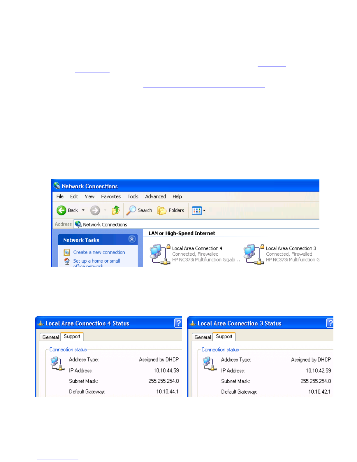
Pre-connection checklist 76
4-3 NIC binding on the Sender
If the Remote Computer has multiple NICs, it is possible for the RGS Sender to be “listening” on one NIC while the
RGS Receiver is trying to establish a connection to the other NIC. There are three methods to deal with multiple
NICs:
1. Manually reconfigure which of the two NICs RGS binds to—see Section 4-3-1, “Manual NIC
reconfiguration.
2. Use the RGS Sender NIC binding properties (introduced at RGS 5.1) to explicitly specify which NIC RGS
binds to—see Section 4-3-2, “NIC reconfiguration using the NIC binding properties
.”
3. Disable one of the NICs and restart the Sender—the Sender will then bind to the enabled NIC. The
disadvantage of this method, of course, is that one of the NICs will no longer be usable.
Methods 1 and 2 are described in the next two sections.
4-3-1 Manual NIC reconfiguration
The RGS Sender binds to the first NIC detected during booting. To determine the IP address of the first NIC,
perform the following steps on the Remote Computer:
1. To view both NICs, click start > Control Panel > Network Connections (see Figure 4-1).
Figure 4-1 Viewing NICs
2. Double-click each LAN icon and the Support tab, which displays the NIC IP address (see Figure 4-2). While
this provides the IP address of each NIC, it does not indicate which NIC is considered the “first NIC”.
Figure 4-2 NIC IP addresses
Page 77

Pre-connection checklist 77
3. To determine which NIC is the first NIC, click Advanced > Advanced Setting (see Figure 4-3). The Advanced
Settings dialog is displayed (see Figure 4-4). The “first NIC” is listed at the top in the Conne
ctions box. In
Figure 4-4, the first NIC is Local Area Connection 3, which (from Figure 4-2) has an IP address of
10.1
0.42.59.
Figure 4-3 Determining the first NIC
Figure 4-4 Advanced Settings dialog
The arrows to the right of the Connections box in Figure 4-4 can be used to change the order of the NICs and,
therefore, which NIC will be used by the RGS Sender. In the above example, the RGS Sender will use Local Area
Connection 3 with an IP address of 10.10.42.59.
To establish a connection from the RGS Receiver to the blade workstation, enter a hostname or IP address in the
HP Remote Graphics Receiver box. If you enter a hostname instead of an IP address, it is possible the hostname
will resolve to the IP address of an incorrect NIC. This could be caused by a number of factors, including how
your DHCP and DNS servers are configured.
If the hostname resolves to the IP address of an incorrect NIC, you can either:
• Enter the NIC IP address (instead of hostname) in the HP Remote Graphics Receiver box.
• Reconfigure your DHCP and DNS servers so that the hostname resolves to the IP address of the correct (first)
NIC.
• Use the Nslookup command to determine the IP address that the hostname resolves to. Then, using the arrow
buttons to the right of the Connections box on the Advanced Settings screen (see Figure 4-4), change the first
NIC to c
orrespond with the IP address returned by Nslookup. After performing this step, you must either
reboot the computer, or restart the RGS Sender (see Figure 4-5).
Page 78
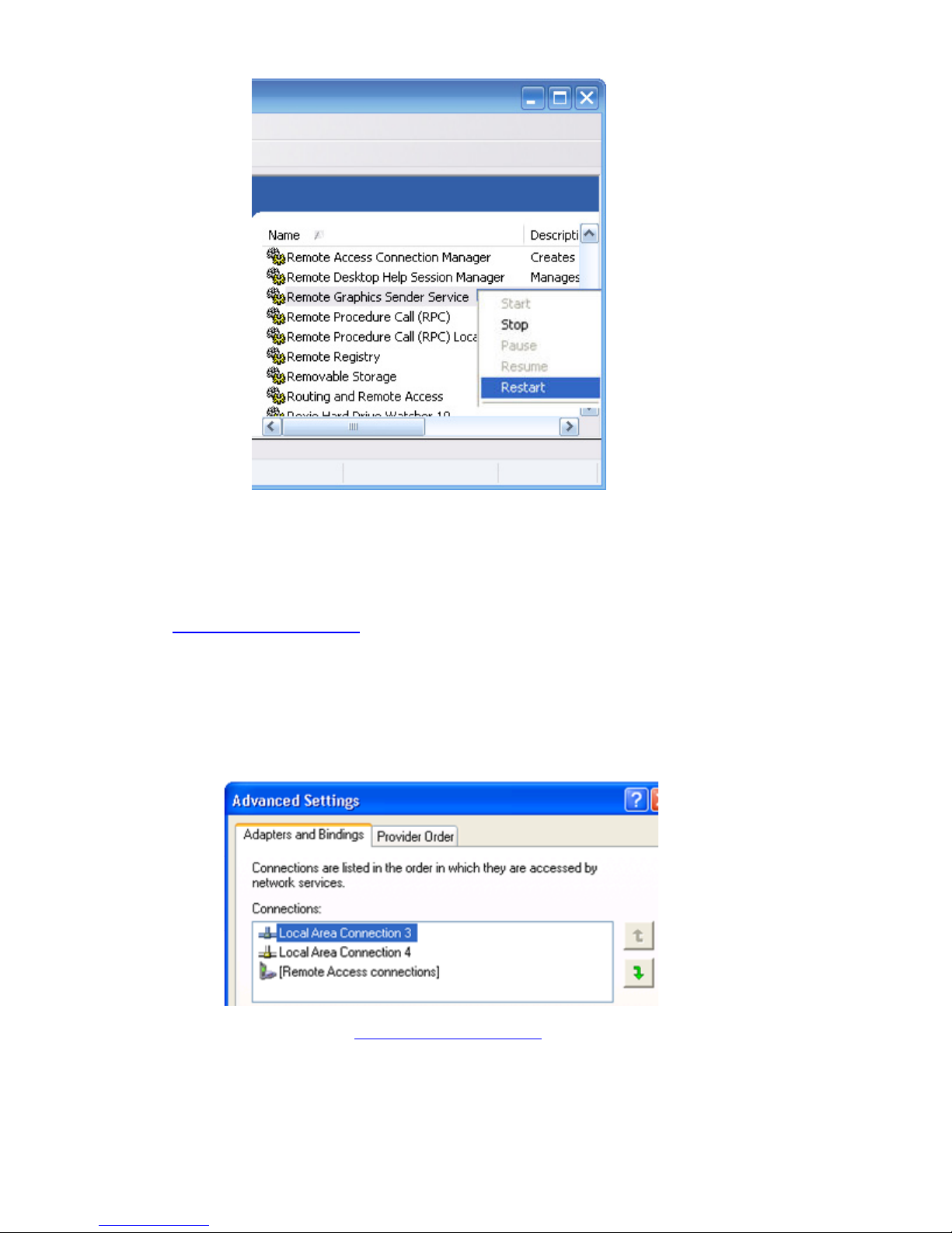
Pre-connection checklist 78
Figure 4-5 Restarting the RGS Sender
4-3-2 NIC reconfiguration using the NIC binding properties
At RGS 5.1, several new Sender properties were added to allow the administrator to configure which NIC(s) the
RGS Sender will listen to for connection requests. For a description of these properties, refer to Section 8-6-6,
“Sender NIC binding properties.”
Figure 4-6 shows how the two NICs can be referenced in numeri
cal sequence in their binding order. The NIC
binding properties permit specification of which NIC (either 0 or 1) the RGS Sender will listen to for connection
requests. For example, using the Rgsender.Network.Interface.1.IsEnabled property, an administrator
can specify that the RGS Sender will listen for connection requests on NIC 1 (corresponding to Local Area
Connection 4), even though NIC 1 is the second NIC in binding order.
Figure 4-6 NIC binding order numerical sequence
Again, refer to Section 8-6-6, “Sender NIC binding properties,” for a description of these properties.
NIC 0
NIC 1
Page 79

Pre-connection checklist 79
4-4 Using RGS through a firewall
New at RGS 5.1.5 is the ability for the Receiver to use the public IP address of the Sender. This feature has been
added to allow RGS to be used through a firewall. To take advantage of this feature, the Sender and Receiver
firewalls must both support NAT (Network Address Translation). In addition, the Sender firewall must support port
forwarding (see Figure 4-7).
Figure 4-7 RGS operation thr
ough a firewall
NOTE: The port used by the RGS Receiver is assigned by the Local Computer OS and can vary. The RGS
Sender listens on TCP/IP port 42966. At RGS 5.2.5, the capability was added to specify the port number used
by the RGS Sender. The default Sender port number is 42966, as noted above. The Sender port number can
be changed using the Rgsender.Network.Port property, as described on page 162. If this property is
used to change the Sender port number from
its default value of 42966, the Sender port number must then be
specified in establishing an RGS connection from the Receiver to the Sender.
Sender
Receiver
Internet
Firewall
NAT-enabled
router
source IP: port dest IP: port
Firewall
NAT-enabled
router
192.168.0.10 : 42966
192.168.0.10 : 42966
source IP: port dest IP: port
192.168.0.1 : 543
source IP: port dest IP: port
15.2.A.B : 543
source IP: port dest IP: port
192.168.0.1 : 678
source IP: port dest IP: port
192.168.0.5 : 3279
source IP: port dest IP: port
15.2.C.D : 678
192.168.0. 5 : 3279
15.2.A.B : 42966
192.168.0.1 : 6 78
15.2.A.B
15.2.A.B : 42966
192.168.0.10 : 42966
192.168.0.5 : 3 27915.2.C.D:678
15.2.C.D
192.168.0.1
NAT
192.168.0.1
NAT
Port
Forwarding
Firewalls can change the source
port numbers (examples shown)
New at RGS 5.1.5 is the ability for the Receiver
to use the public IP address
of the Sender
This port number
can vary.
Public IP
addresses
Page 80

Using RGS 80
5 Using RGS
This chapter describes how to use RGS to establish a connection from a Local Computer to a Remote Computer,
including:
• Using RGS in Normal Mode
• Functionality and use of the Receiver Control Panel
• Setup Mode
• Remote Display Window Toolbar
• Remote Computer monitor blanking
• Linux connection considerations
• RGS login methods
• Collaborating
5-1 Using RGS in Normal Mode
Normal Mode is one of the two RGS operating modes—see Section 2-11, “RGS operating modes.” Normal
Mode is the simplest means of establishing a connection—you enter the IP address or hostname of the Remote
Computer in the Local Computer Receiver Control Panel, and click Connect.
NOTE: The second RGS operating mode, Directory Mode, is described in Chapter 7.
Before attempting to connect to a particular Remote Computer for the first time, HP recommends that you verify
that the Remote and Local Computers satisfy the checklist in Chapter 4, “Pre-connection checklist.” The checklist in
Chapter 4 can also be used as a troubleshooting aid if a con
nection attempt fails. After verifying the preconnection checklist, start the Receiver on the Local Computer. This can be done from the start menu or from the
command line (see Figure 5-1).
Figure 5-1 Starting the Receiver on Windows
The RGS Receiver supports the following command line options for the Windows executable, rgreceiver.exe,
and the Linux executable, rgreceiver.sh:
[-directory [file]]
[-nosplash]
[-v | -ver | -version]
[-h | -help | -?]
[-Rgreceiver.
propertyname=value]
-directory [file]—Starts the Receiver in Directory Mode. If the optional file path is specified, the file is
opened and used to look up the Remote Computers assigned to the user. If a file is not specified, the user is
prompted to enter a path to the directory file. For information on Directory Mode, see Chapter 7, “Using Directory
Mode.”
-nosplash—Disables display of the splash screen when the Receiver starts.
[-v | -ver | -version]—Displays the Receiver version information.
[-h | -help | -?]—Displays the Receiver command line options that are listed on this page.
-Rgreceiver.propertyname=value—Can be used to specify one or more RGS Receiver properties. See
Chapter 8, “RGS properties
,” for general information on RGS properties. For information specifically on RGS
Receiver properties, see Section 8-5, “RGS Receiver properties
.”
From start
menu
From command
line
Page 81

Using RGS 81
After the Receiver starts, you’ll see the Receiver Control Panel (see Figure 5-2).
Figure 5-2 Receiver Control Panel
To create an RGS connection, enter the hostname or IP address of the Remote Computer in the Hostname dialog
box, and press Enter or click Connect.
NOTE: At RGS 5.2.5, the capability was added to specify the port number used by the RGS Sender. The default
Sender port number is 42966. The Sender port number can be changed using the Rgsender.Network.Port
property. If this property is used to change the Sender port number from its default value of 42966, the Sender port
number must then be specified in the above Hostname dialog box, in either of the following formats:
hostname:port number
IP address:port number
For example, if the Rgsender.Network.Port property is used to change the Sender port to 42970, the Sender
IP address in Figure 5-2 would need to be modified to include the port number, as follows:
15.2.76.29:42970
Provide a username and password, as prompted. If the connection succeeds, the Remote Display Window will be
displayed on the Local Computer, showing the desktop session of the Remote Computer (see Figure 5-3).
Figure 5-3 Remote Display Window
Local Computer Desktop
Remote Display Window
Local Computer Desktop
Remote
Display
Window
Page 82

Using RGS 82
IMPORTANT: If the connection attempt fails, refer to Chapter 4, “Pre-connection checklist,” for a list of conditions
which must be met in order for a connection to be established.
IMPORTANT: If your RGS Sender is not yet licensed, the error dialog in Figure 2-3 will be displayed in the
Remote Display Window. For i
nformation on Sender licensing, see the HP Remote Graphics Software Licensing
Guide, available at www.hp.com/support/rgs_manuals
.
IMPORTANT: On Linux, The Receiver Control Panel will not stay on top of other windows in the desktop, and can
therefore get lost. Also, for session managers that support multiple desktops, the Receiver control panel will not,
by default, show up in all desktops. Refer to Section 5-1-2, “Setup Mode
,” to understand how to raise the
Receiver Control Panel to the top of the window stack.
In Normal Mode, the Local Computer can connect to only one Remote Computer at a time, as described in
Section 2-8-2, “One-to-one connection
.” If an attempt is made to connect to a second Remote Computer using the
Receiver Control Panel, the connection to the first Remote Computer is terminated.
5-1-1 Receiver Control Panel
Now that a connection has been established, the Receiver Control Panel is described in more detail. The Receiver
Control Panel is used to perform the following tasks:
• Establish a connection: To establish a connection to a Remote Computer, enter the hostname or IP address of
the computer in the Hostname field. Press Enter, or click the Connect button to connect to the Remote
Computer. The selector on the right side of the text box displays a history of previously connected computers
that can be selected.
• Close a connection: To close a connection, press the Disconnect button.
• Enter Setup Mode: To enter Setup Mode, press the Setup Mode button. In Setup Mode, the Receiver
suspends mouse and keyboard input to the Remote Computer, allowing the user to use the mouse and
keyboard to interact with local Remote Display Windows. See Section 5-1-2, “Setup Mode
,” for more
information.
• View advanced operations: Click Advanced>>> to view the tabs which provide access to many of the
advanced capabilities of RGS.
• Display help: Click Help to display the online help. On Linux, the online help is displayed separately in a
web browser, such as Mozilla. On Windows, the online help is displayed using the CHM file viewer
hh.exe.
• Display program information: Click About to display RGS program and copyright information.
The Receiver Control Panel contains a status bar at the bottom of the window. The status bar provides information
that describes the current state of the RGS Receiver. For example, it displays the messages “connection in
progress”, “connection succeeded”, and “connection failed.” The status bar can be useful in diagnosing
connection problems because it also displays the general reason for a connection failure, such as “Authorization
Failed” or “Authentication Failed”.
5-1-2 Setup Mode
Depending on how you configure RGS on the Local Computer, the Remote Display Window may cover the entire
Local Computer monitor. Furthermore, the Remote Display Window may be set to borderless—therefore, the
window won’t have the title bar and borders that normally allow the window to be moved, minimized, and
resized. Such a configuration raises a number of questions, including:
• How do you move or resize the window absent a title bar and borders?
• If multiple Remote Display Windows are covering each other, how do you select a particular Remote Display
Window to view?
Complicating the situation is that all keyboard and mouse events in the Remote Display Window are sent to the
Remote Computer for processing. Therefore, the keyboard and mouse cannot be readily used to interact with the
locally-displayed Remote Display Window.
To address this situation, RGS provides Setup Mode. In Setup Mode, transmission of keyboard and mouse events
to the Remote Computer is suspended—instead, the keyboard and mouse can be used to interact with the Remote
Display Window on the Local Computer. In Setup Mode, you can perform a number of operations, including:
• Move a borderless Remote Display Window
• Raise a particular Remote Display Windows that is being obscured by another Remote Display Window
Page 83

Using RGS 83
Setup Mode can be activated in two ways:
• By clicking the Setup Mode button on the Receiver Control Panel (see Figure 5-2). This presumes, of course,
that the Receive
r Control Panel is visible.
• By typing a special key sequence on the keyboard, called a hotkey sequence.
The hotkey sequence method of activating Setup Mode is required in situations where, for example, the Remote
Display Window is borderless, and is covering the entire Local Computer monitor, including the Receiver Control
Panel. Because the Receiver Control Panel is obscured, its Setup Mode button is inaccessible. The default hotkey
sequence to enter Setup Mode is:
Shift press, space press, space release
When the Receiver detects this key sequence, it does not send the key sequence to the Remote Computer—
instead, the Receiver activates Setup Mode on the Local Computer, as denoted by dimming of the Remote Display
Window (see Figure 5-4).
Figure 5-4 Dimming of
the Remote Display Window in Setup Mode
The default hotkey sequence can be changed using the Hotkeys tab in the Receiver Control Panel (see Section 6-5,
“Hotkeys
”). As long as the Shift key is held down (following the Shift press, space press, and space release hotkey
sequence used to enter Setup Mode), Setup Mode remains active. When the Shift key is released, Setup Mode
exits. In contrast, the Setup Mode button on the Receiver Control Panel toggles the state of Setup Mode each time
the user clicks on the button.
NOTE: In Normal Mode, only a single Remote Display Window can be displayed on the Local Computer.
Displaying multiple Remote Display Windows on the Local Computer requires using Directory Mode (see
Chapter 7, “Using Directory Mode
”).
Page 84
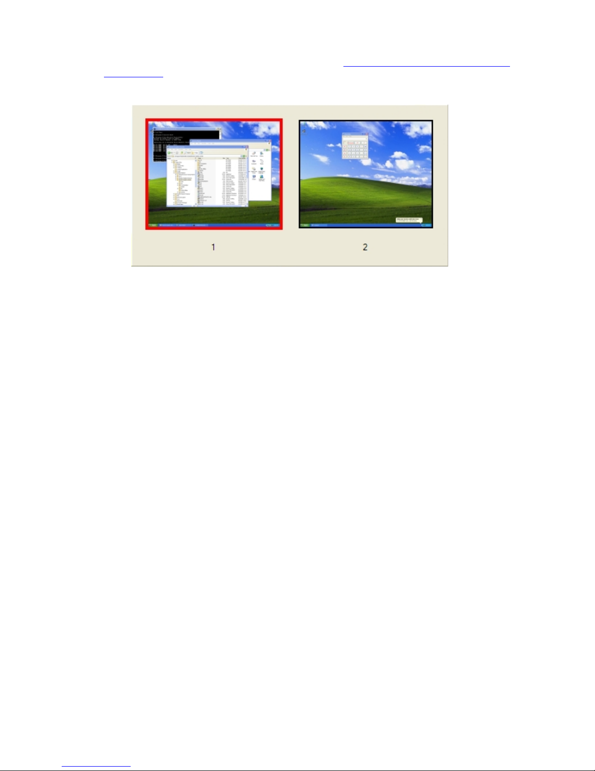
Using RGS 84
If Setup Mode is activated by the hotkey sequence (as opposed to the Setup Mode button), and you have multiple
Remote Display Windows on your computer, you can bring up the Remote Display Window selection dialog to
view a thumbnail image of each Remote Display Window (see Selecting Remote Display Windows while in
Directory Mode).
Figure 5-5 Remote Display Window selection dialog
The Remote Display Window selection dialog is only displayed in Directory Mode—this is the mode that supports
multiple Remote Display Windows.
Page 85
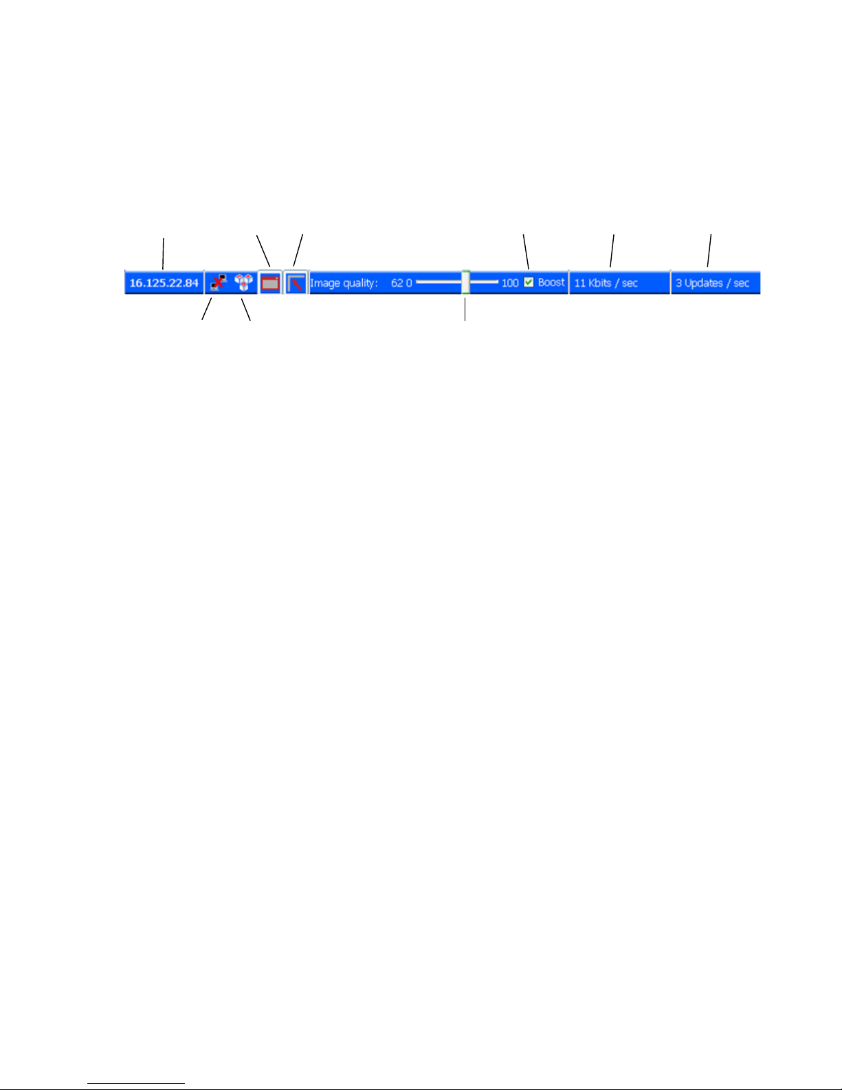
Using RGS 85
5-1-3 Remote Display Window Toolbar
The Remote Display Window Toolbar provides information on the RGS connection, and allows several RGS
parameters to be controlled. The toolbar is positioned at the top of the Remote Display Window (see Figure 5-6),
and is toggled on and off by pressing the H key while in Setup Mode. In this particular case, Setup Mode can be
entered by either method—the Setup Mode button or the hotkey sequence—and the H key can be used to display
the toolbar.
Figure 5-6 Remote Display Window Toolbar
The Remote Display Window Toolbar provides the following:
• hostname—The hostname or IP address of the Remote Computer
• disconnect button—Disconnects the current RGS session
• CTRL-ALT-DEL button—Sends the CTRL-ALT-DEL key sequence to the Remote Computer. Some key sequences,
such as CTRL-ALT-DEL, are trapped by the Local Computer, and therefore are not forwarded to the Remote
Computer. This button allows the user to send a CTRL-ALT-DEL sequence to the Remote Computer without
using the keyboard.
• Borders button—Adds or removes window borders and decorations on the Remote Display Window.
• Snap button—When selected, this option causes the Remote Display Window to snap to the edges of the
monitor whenever the boundaries of the window are within 30 pixels of any edge of the monitor.
• Image quality slide bar—Sets the image quality and, therefore, the amount of compression. Higher image
quality reduces the amount of compression, and therefore consumes greater network bandwidth.
• Boost checkbox—When checked, will improve (boost) image quality for certain types of images, primarily
images containing significant amounts of text or lines. Because of the high contrast ratio between adjacent
pixels, such images often don’t compress well. When the Boost checkbox is checked, such high contrast
cases will be compressed in a manner to better preserve their visual quality, but at the possible expense of
higher network bandwidth and/or lower image update rates. HP recommends that you experiment with
different settings of the image quality slide bar and the Boost checkbox to find the optimal settings for your
environment.
The Boost checkbox was added beginning with RGS 5.2.6, and requires that both the RGS Sender and
Receiver be version 5.2.6 or later. The Boost setting can also be controlled by the
Rgreceiver.ImageCodec.IsBoostEnabled Receiver property.
• Network bandwidth—Displays the current network bandwidth consumed by this connection.
• Image update rate—Displays the number of image updates per second for this connection.
hostname or
IP address of
Remote Computer
border button
snap button
disconnect
button
CTRL-ALT-DEL
button
image quality slide bar
image update rate
network bandwidth
Boost checkbox
Page 86

Using RGS 86
5-1-4 Remote Computer monitor blanking operation
For an overview of Remote Computer monitor blanking, see Section 2-13, “Remote Computer monitor blanking
overview.” Monitor blanking on the Remote Computer is provided for security, so that the primary user’s desktop
session on the Remote Computer is not visible if a monitor is connected to the Remote Computer.
Monitor blanking is supported on all Windows computers that support gamma. On these computers, the default
behavior is that the Remote Computer monitor will blank to black when the user connects and logs in. The Remote
Computer monitor will unblank when the user disconnects or logs out. Below are several additional details on
monitor blanking on HP xw Personal Workstations:
• The one element on the monitor that does not go blank is the cursor.
• Blanking can take up to two seconds from the time the primary user logs in or reconnects until the time that
the monitor is actually blanked.
• The HP xw Personal Workstations also block input from a directly-connected keyboard and mouse when
monitor blanking is occurring. When keyboard or mouse input is received by the Remote Computer, the
monitor will enter the display powersave mode, and the cursor will be blanked as a result.
• An exception to input blocking is the CTRL-ALT-DEL key sequence. When this sequence is received by the
Remote Computer from a directly-connected keyboard, the Remote Computer desktop will display the login
dialog on the Local Computer. The Remote Computer monitor will remain blank while this occurs but the
monitor will exit its powersave mode, and keyboard input will become unblocked until this dialog is
dismissed.
If monitor blanking is enabled but the Remote Computer is unable to blank the display (because, for example, the
computer is not one of the supported computers listed previously), a warning dialog is displayed on the Local
Computer (see Figure 5-7).
Figure 5-7 Loc
al Computer warning dialog if the Remote Computer is unable to blank its monitor
Click on Warning: Sender Monitor is Viewable to view the associated message dialog (see Figure 5-8).
Figure 5-8 Message dialog
Page 87

Using RGS 87
The Remote Computer monitor blanking feature can be disabled by setting the following Sender property to 0
(false).
Rgsender.IsBlankScreenAndBlockInputEnabled
If this property is set to 0, monitor blanking will be disabled, meaning that a monitor connected to the Remote
Computer will display the user’s desktop session. Furthermore, because monitor blanking is disabled, the warning
dialog shown in Figure 5-7 will not be displayed. For more details on this property, see Section 8-6-2, “Sender
general properties.”
5-2 Linux connection considerations
5-2-1 Full-screen crosshair cursors
Certain applications that use large crosshair cursors (for example, PTC ICEM Surf uses a full-screen crosshair
cursor) will not display correctly on the Receiver. Full-screen crosshair cursors can be disabled by typing the
following in a terminal window:
/usr/contrib/bin/X11xprop -root -remove _SGI_CROSSHAIR_CURSOR
/usr/contrib/bin/X11xprop -root -remove _HP_CROSSHAIR_CURSOR
This will force the application to use an X cursor, which will display correctly on the Receiver.
5-2-2 Gamma correction on the Receiver
The color on a 3D application on the Sender can look incorrect when displayed on a Receiver. This is because the
gamma of the Local Computer monitor may not match the gamma of the Remote Computer monitor. To correct
this, any tool that will adjust the gamma for a display can be used. Some tools will adjust the gamma for the
entire monitor, while others will adjust the gamma on a per-window basis. Per-window tools that can be used to
adjust only the Receiver window will provide the best results.
5-2-3 Black or blank connection session with the Linux Sender
Connection to an X server that is configured with less than 24-bit or 32-bit default visuals (depending on the
graphics device) will cause the Linux Sender to generate a black or blank connection screen. For example, some
default installations may configure a 16-bit visual in /etc/X11/XF86Config after the installation. Reconfiguring the
X server to serve 24-bit (or 32-bit) default visuals, and restarting the X server will usually fix the black or blank
connection situation.
Page 88
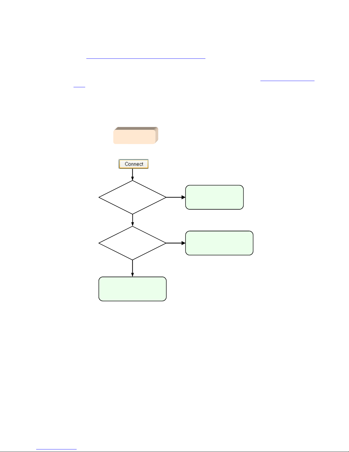
Using RGS 88
5-3 RGS login methods
RGS provides three methods for the local user to log into a Remote Computer:
• Standard Login—supported on Windows and Linux Senders. For an overview of Standard Login, see Section
2-9, “Establishing an RGS connection using Standard Login
.”
• Easy Login—supported on Windows XP Professional Senders on HP blade workstations
• Single Sign-on—supported on Windows XP Professional Senders on HP blade workstations and HP personal
workstations. For an overview of Single Sign-on and Easy Login, see Section 2-10, “Single Sign-on and Easy
Login.”
The log in method that is used is dependent on how the Sender was installed—see Figure 3-4. If neither Easy
Login nor Single Sign-on was enabled during installation, Standard Login is used (see Figure 5-9).
Figure 5-9 Log in selection flowchart
Each of these login methods is described in the following three sections.
5-3-1 Standard Login
Standard Login is the process by which a local user attempts to connect to a Remote Computer that has neither
Single Sign-on nor Easy Login enabled. Figure 5-10 on the next page shows the Standard Login process. Figure
5-10 also shows the process followed by the primary user after logging in.
N
is
Easy Login
enabled
?
Y
attempt to log in
using Easy Login
is
Single Sign-on
enabled
?
Y
attempt to log in
using Single Sign-on
attempt to log in
using Standard Login
N
local user
Page 89

is
another
user already
logged into the
Remote Computer
(the primary
user)
?
N
has
local user
logged in
?
N
Y
N
Y
Y
has
another user
logged in
?
N
Y
do the
credentials of
local user match
the credentials of
the primary
user?
RGS authentication dialog
Attempt to connect to
Remote Computer
Y
Windows-to-Windows
connection AND local user
credentials match any
credentials
on Remote Computer
?
Y
N
silent
authentication
authentication
succeeded
?
N
Y
Remote Display
Window is terminated
when another user
logs in, local user
will need to reconnect
If another user attempts to connect
to the Remote Computer with the
same credentials as the local user,
the local user Remote Display Window
below will terminate.
RGS connection
established
Y
Login dialog
in Remote
Display
Window
N
Remote Display Window
is terminated when
primary user unlocks
desktop or re-connects, local
user will need to reconnect
Remote
Display
Window
This dialog is displayed
for the primary user
Remote
Display
Window
N
Is
desktop
locked or is primary
user disconnected
(but still logged
in)
?
Y
local user can unlock
local user
is now the
primary user
N
In both cases, the local user
becomes the new primary
user and the prior primary
user is disconnected.
This is the collaboration path – multiple local users can
connect to the primary user’s desktop, subject to
authorization by the primary user.
Is
desktop
locked or is primary
user disconnected
(but still logged
in)
?
N
primary user
press
?
Remote Display
Window terminated
did someone
else log in with
my credentials
?
N
N
Y
Remote Display
Window terminated
Y
log out
?
Y
lock screen
?
Y
N
N
Now a local user with an
authenticated connection
did
someone else
log in with my
credentials
?
N
Y
press
?
Y
N
did I
unlock screen
?
N
Y
Remote
Display
Window
is
another
user attempting
to connect
?
Y
N
Remote
Display
Window
did
someone else
log in with my
credentials
?
N
Y
local user
now
a local
user
local user
attempt to log in
using Standard Login
“authenticating the connection”
Figure 5-10 Local user Standard Login process and primary user flowchart
Respond
to dialog
does
primary user authorize
connection
?
Using RGS 89
Page 90

Using RGS 90
5-3-2 Easy Login
The Easy Login flowchart is shown in Figure 5-11. If the Easy Login conditions are met, the RGS connection
authentication step is skipped, and the local user is presented either with the Welcome to Windows login dialog
or the locked screen dialog.
Figure 5-11 Easy Login process
IMPORTANT: There are several Sender setup issues that can prevent an Easy Login connection to the RGS
Sender. The RGS Diagnostics Tool programmatically detects several of these issues, and suggests possible
solutions. See the section “Using the RGS Diagnostics Tool on Windows
” for more details.
is
another
user alr eady
connected to the
Remote Computer
or already logged
into it
?
Y
N
• Remote Computer must be an HP blade workstation
• Remote Computer must be running Windows
• Easy Login must be enabled on the Remote Computer
• No other RGS connection can exist
attempt to log in
using Standard Login
Enter CTRL-ALT-END (to trigger the CTRL-ALT-DEL response)
Local user will see the Welcome to Windows
login dialog or the locked screen dialog
Local user can attempt to log in or unlock screen
Windows desktop if login or unlock successful
attempt to log in
using Easy Login
local user
Page 91

Using RGS 91
5-3-3 Single Sign-on
The Single Sign-on flowchart is shown in Figure 5-12. If the Single Sign-on conditions are met, the user
authenticates the RGS connection, and the Windows log in or unlock step is skipped. The user is presented with
the Windows desktop following RGS connection authentication.
Figure 5-12 Single Sign-on process
local user
attempt to log in
using Single Sign-on
• Remote Computer must be an HP personal or blade workstation
• Remote Computer must be running Windows
• Single Sign-on must be enabled on the Remote Computer
• No other RGS connection can exist
is
another
user already
connected to the
Remote Computer
or already logged
into it
?
Y
N
attempt to log in
using Standard Login
authentication
succeeded
?
N
Y
Windows desktop if authentication successful
Page 92
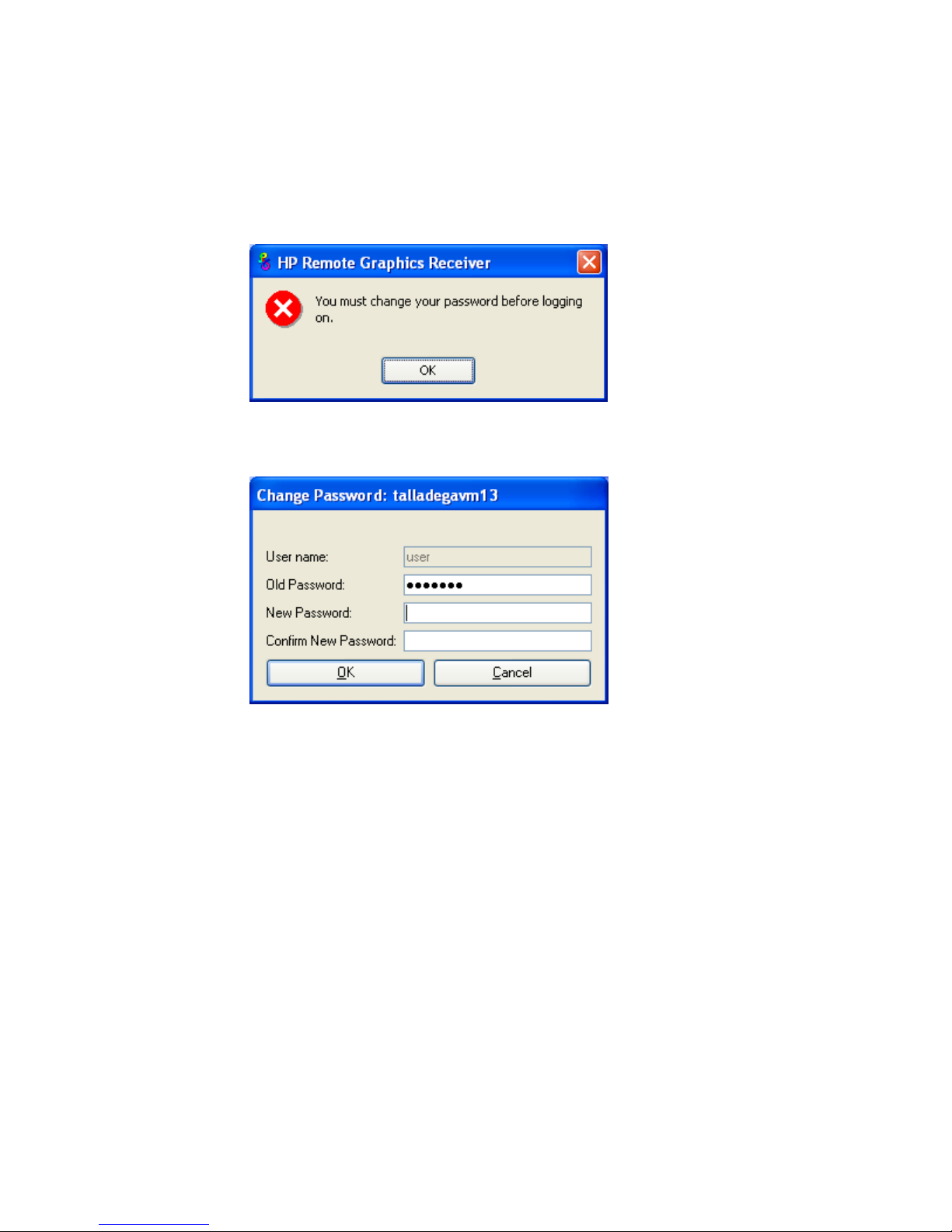
Using RGS 92
5-4 Changing your password
In RGS 5.0 and earlier, attempting to make a connection with an expired password would generate an
Authentication failed! error message. In this situation, the user would either need direct access to the Remote
Computer to change the password, or would need to call IT to have the password changed.
Starting at RGS 5.1, you can change an expired password from the RGS Receiver. If you enter an expired
password, you will see a dialog stating that the password must be changed (see Figure 5-13).
Figure 5-13 Di
alog indicating that the password must be changed
After clicking OK, you’ll see the Change Password dialog (see Figure 5-14).
Figure 5-14 Change Password dialog
Enter the requested information to change your password.
Page 93
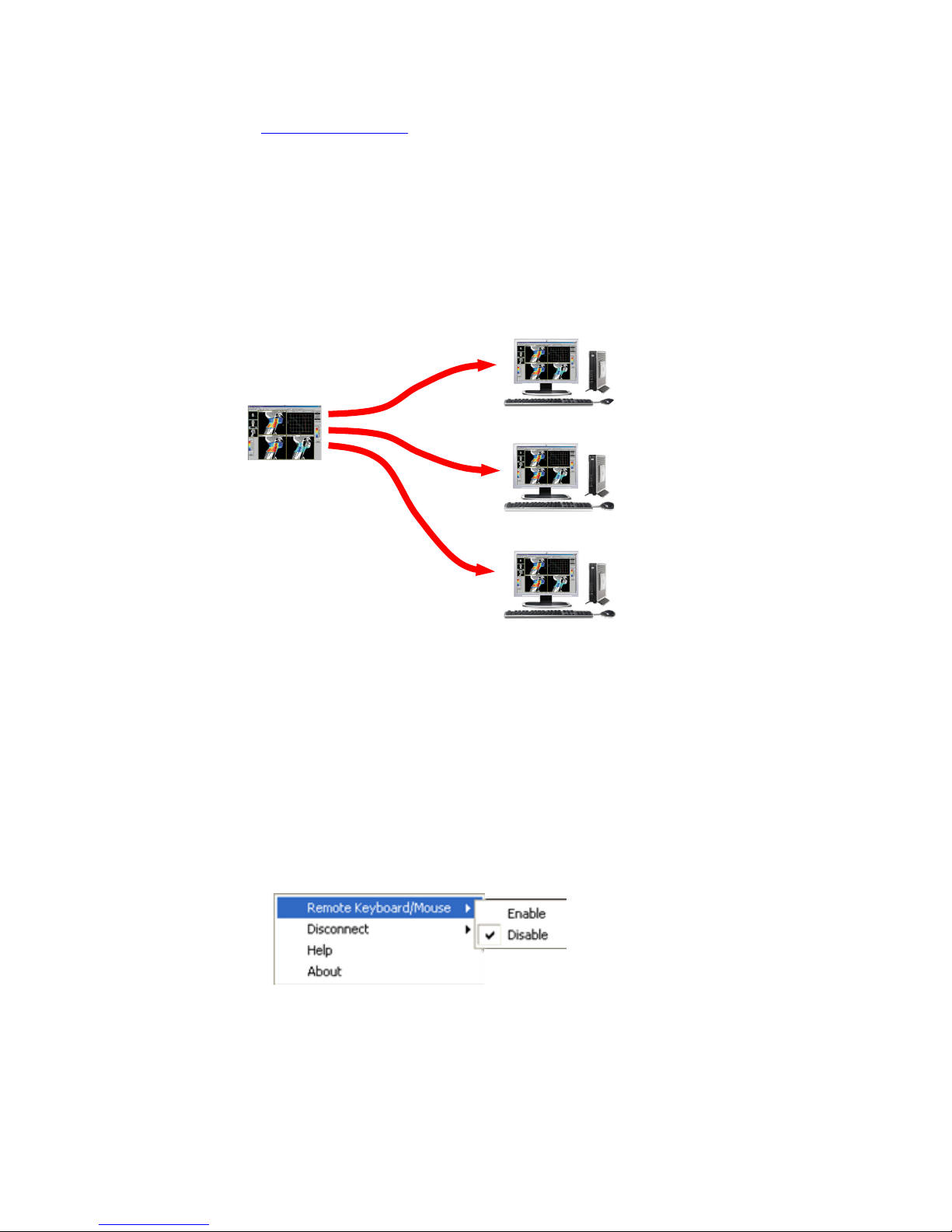
Using RGS 93
5-5 Collaborating
RGS enables the primary user to share his or her desktop session with several local users simultaneously (see
Section 2-8-4, “One-to-many connection”). This feature can be used in a variety of collaborative scenarios
including classroom instruction, design reviews, and technical support.
5-5-1 Creating a collaboration session
A collaboration session is created when one or more local users are authorized by the primary user to connect to
the primary user’s desktop session. This allows all users, primary and local, to view and interact with the primary
user’s desktop (see Figure 5-15)
Figure 5-15 Multiple local users can view and interact with the primary user’s desktop
The user currently controlling the mouse and keyboard is called the floor owner. Only one user, the floor owner,
can interact with the desktop at a time. To transition the floor owner, the current floor owner must cease using the
keyboard or mouse for a short period of time (0.5 seconds). If another user uses the mouse or keyboard while the
current floor owner is inactive during this .5 second period, floor ownership transfers to the new user.
In a collaboration session, the shape of the local cursor is modified for the floor owner. For the other remote users,
the local cursor is left unchanged, and a remote cursor is displayed in the Remote Display Window.
Use of the mouse and keyboard by non-primary users can be disabled by the primary user using the Sender GUI
(see Figure 5-16). Authorized local users will still be able to view the primary user’s desktop,
but will be unable to
interact with it.
Figure 5-16 Disabling of the local users’ mice and keyboards by the primary user
Remote Computer
Local Computers
Primary User
Local User 1
If the Remote Computer
is a blade workstation,
it will typically not have
a monitor connected to
it. The above image
associated with the
Remote Computer is
for clarity, to show
the source of the
desktop image
(logged into
Remote Computer)
(viewing primary
user’s desktop
session)
Local User 2
(viewing primary
user’s desktop
session)
Page 94

Using RGS 94
Connection between a Local Computer and a Remote Computer is permitted only if the primary user allows the
connection. A question dialog, stating the domain and user name of the local user attempting a connection, is
displayed on the Remote Computer desktop when a local user attempts to connect (see Figure 5-17). All currentlyconnected local users will also
see this dialog because they are currently viewing the Remote Computer desktop.
Figure 5-17 Primary user dialog to authorize a local user to connect to the primary user’s desktop
The different cases for establishing a collaborative session are:
• If no one is logged into the Remote Computer desktop (in other words, there is no primary user), all
authenticated users are connected, and can view the Windows login desktop. However, when any one user
logs into the Remote Computer desktop (and, therefore, becomes the primary user), all other authenticated
users (who are viewing the Windows login desktop) will be disconnected as a security precaution.
• If the primary user authorizes a connection from a local user, the new user connects to the Remote Computer
and can view its desktop.
• If the primary user does not allow the connection, the new user will be unable to connect.
• On Windows, if the primary user disconnects, the desktop is locked, but the Receivers will remain
connected.
• On Linux, if the primary user disconnects, the desktop is locked, and all users are disconnected.
• If the local user connecting to the primary user’s computer is the same user as the primary user, the
collaboration dialog is not displayed, and the connection is allowed.
On Windows, the Sender desktop icon in the system application tray displays the status of connections. The icon
animates when Receivers are connected. On Linux, the Sender GUI is present on the desktop and displays
connection status.
All Receivers can be easily disconnected from the HP Remote Graphics icon located in the system tray or from the
Sender GUI by right-clicking on the icon or GUI. This is useful when hosting collaborative session, such as in a
classroom environment, and the session ends.
5-5-2 Collaboration notification dialog
The Windows Sender displays a collaboration notification dialog when non-primary users are connected. This
Sender-created dialog appears in each Remote Display Window that is connected to the Sender. The dialog
displays a list of domain\usernames for each user connected to the Remote Computer (see Figure 5-18).
Figure 5-18 C
ollaboration notification dialog displayed on the Sender and in each Remote Display Window
When the collaboration notification dialog is displayed, it indicates there are multiple connections to the Remote
Computer desktop. Primary and non-primary users are identified using different fonts in the notification dialog. The
primary user is italicized and listed first. Non-primary usernames follow, and are displayed using a normal font.
Figure 5-18 shows three active connections, one a primary user and the other two non-primary users. A small
button wi
th an “X” is displayed next to all non-primary usernames. Pressing this button disconnects the
corresponding non-primary user.
Page 95

Using RGS 95
All non-primary users can be disconnected using the Sender GUI. Figure 5-19 shows the Windows Sender GUI
selection that can be used to disconnect non-primary users.
Figure 5-19 Windows Sender GUI to disconnect non-primary users
Prior to RGS 5.2.0, the collaboration notification dialog could not be hidden (although it could be moved
elsewhere on the desktop by clicking in the dialog and dragging it). Beginning at RGS 5.2.0, a new Sender
property has been added—the Rgsender.IsCollaborationNotificationEnabled property (see Section
8-6-2, “Sender general properties
”). This property allows the user to enable or disable display of the collaboration
notification dialog.
CAUTION: Caution is advised in disabling the collaboration notification dialog because neither the Remote User (if
present) nor the Local Users will be notified who is participating in a collaboration session. Furthermore, if display of
the collaboration notification dialog is disabled, the warning dialog in Figure 5-7 (which is displayed when the
Remote Computer is unable to
blank its monitor) will also be prevented from being displayed.
If the collaboration notification dialog is being displayed, the Sender will remove it when all non-primary
connections terminate.
Page 96
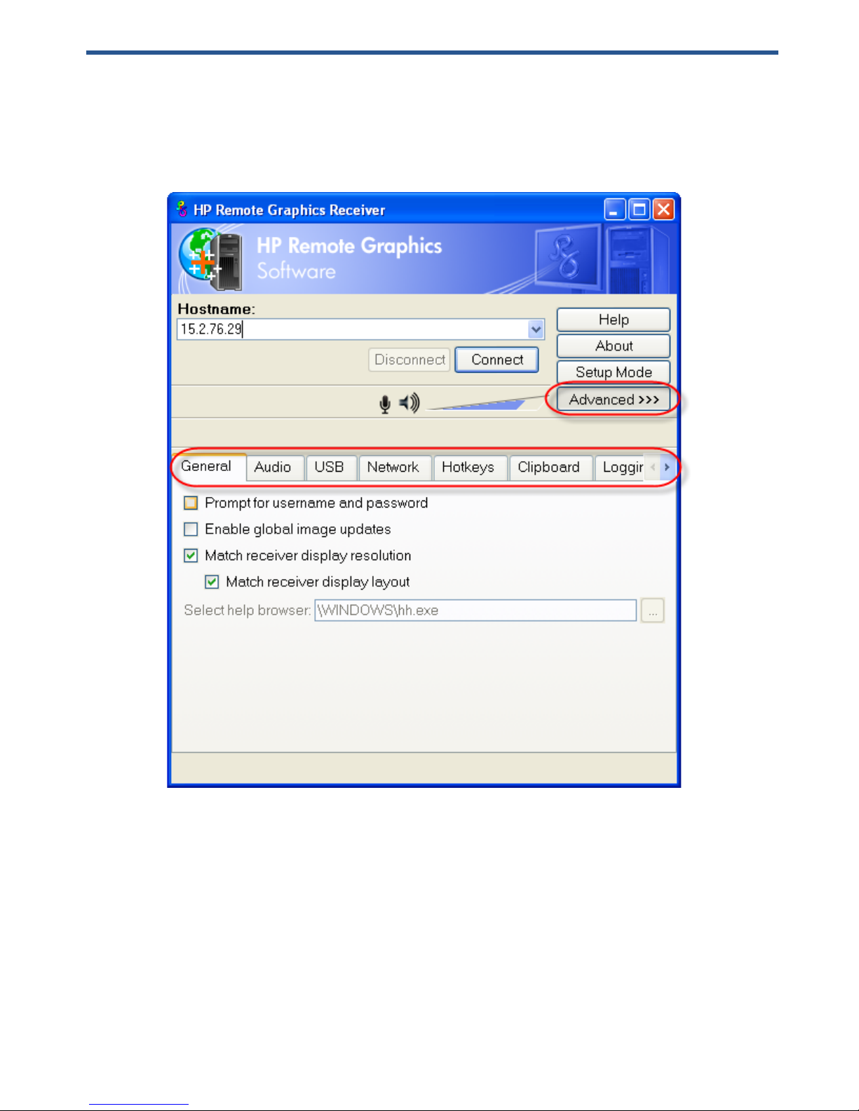
Advanced capabilities 96
6 Advanced capabilities
This chapter discusses the many advanced capabilities of RGS. Click on the Advanced>>> button in the Receiver
Control Panel to display the tabs shown in Figure 6-1.
Figure 6-1 Tabs to access advanced RGS capabilities
The capabilities available under each of these tabs will be described in detail. Unless required for clarity, the
portion of the Receiver Control Panel above the tabs will not be shown.
Page 97
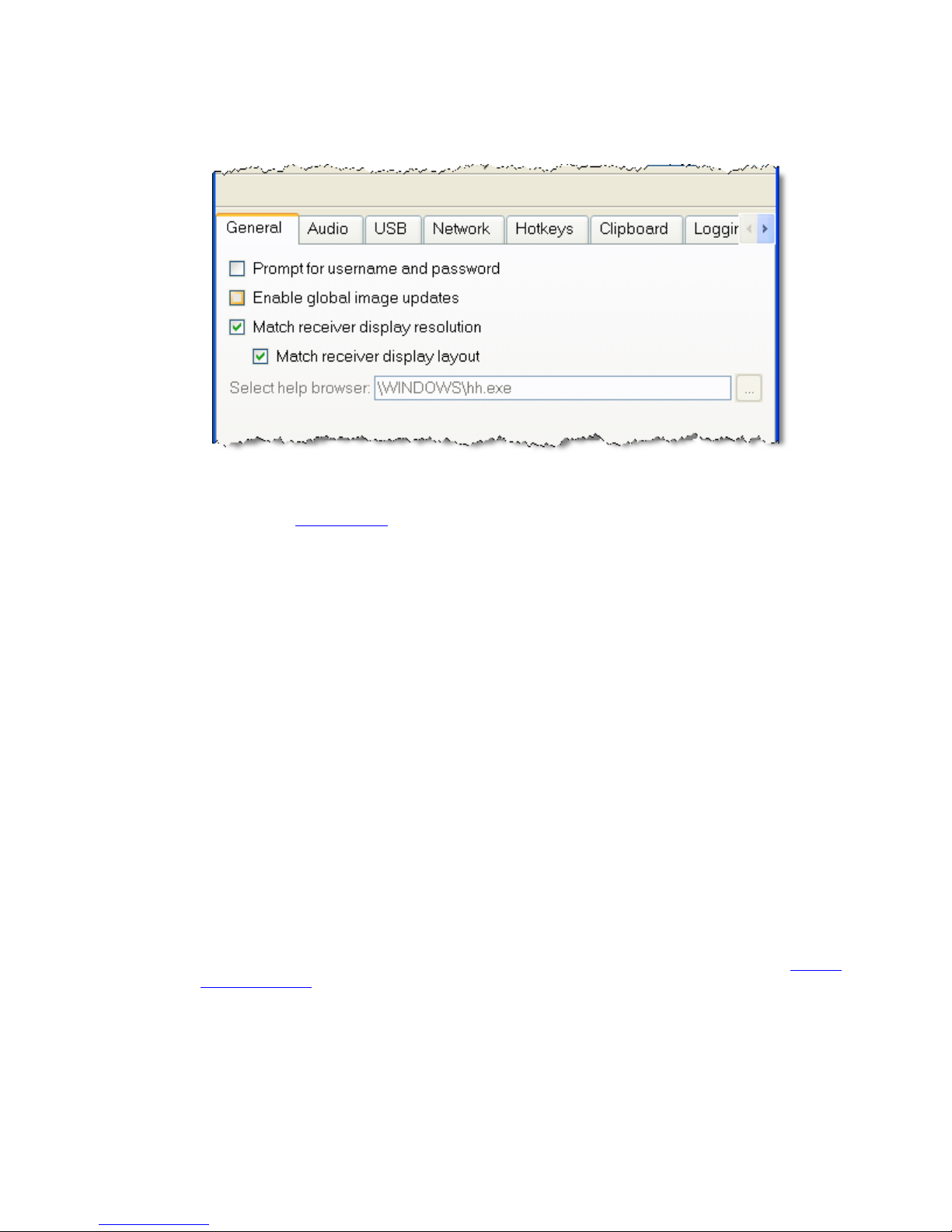
Advanced capabilities 97
6-1 General options
The options available under the General tab are shown in Figure 6-2.
Figure 6-2 General tab options
The options available under the General tab are:
• Prompt for username and password—In certain scenarios (such as silent authentication as described in
Section 5-3-1, “Standard Login
”), the Receiver will not prompt the local user for a domain, username, and
password. If the local user desires a prompt in order to enter an alternate domain, username, and password,
the user can check this box. If checked, the authentication dialog is always displayed when the Connect
button is clicked. This is advantageous on Sender/Receiver pairs running Windows and Directory Mode
with different connection needs for each session.
• Enable global image updates—When checked (enabled), all of the individual regions of the Remote
Computer Sender frame buffer that have changed since the last update of the Remote Display Window are
combined into a single update that encloses all of the regions that have changed. The advantage of this
approach is that there is no perceptible painting of the individual regions as can sometimes be observed
when this option is disabled. However, the single rectangle can include a large number of pixels that have
not changed since the last update, and thus can significantly reduce the update rate. Enabling this option
may improve visual quality at the expense of performance.
• Match receiver display resolution—When checked, the Receiver will negotiate with the Remote Computer
Sender to have the Sender adjust its display resolution to match the Receiver display resolution. If the
Sender is unable to match the resolution of the Receiver, a warning dialog is issued to the local user.
• Match receiver display layout—This checkbox is new with RGS 5.1.3. When checked, the Receiver (Local
Computer) will try to set the layout of the Remote Computer physical displays to have the same display
layout and resolution as the Receiver displays. If the Sender is unable to match the layout and resolution of
the Receiver physical displays, the Sender will try to just match the Receiver display resolution. For example,
if the Receiver has two physical displays in a 1x2 layout and a overall virtual display resolution of
2560x1024 (1280x1024x2), the Receiver will try to set the Sender to the same layout and resolution. If that
fails, the Receiver will try to set a single Sender physical display resolution of 2560x1024. If that fails, an
error is reported to the local user.
For information on the properties associated with the above two checkboxes, see Section 8-5-3, “Receiver
general properties”—specifically, see the Rgreceiver.IsMatchReceiverResolutionEnabled and
Rgreceiver.IsMatchReceiverPhysicalDisplaysEnabled properties.
• Select help browser—Enables the user to specify a web browser, such as mozilla, to display online help.
This option is not available on Windows (grayed out) because the default web browser is automatically read
from the Windows Registry.
Page 98

Advanced capabilities 98
6-2 Remote audio operation
For an overview of remote audio, see Section 2-17, “Remote audio overview.” Before describing the RGS audio
capabilities available under the Receiver Control Panel Audio tab, Sender audio configuration and calibration are
described.
6-2-1 Configuring audio on the Microsoft Windows XP Professional Sender
To configure audio on the Microsoft Windows XP Sender, open the Sound and Audio Devices Properties dialog in
the Windows Control Panel, and select the Audio tab (see Figure 6-3).
Figure 6-3 Sound and Audio Devices Properties dialog
The first step is to configure the Sound playback device (if used) and the Sound recording device (if used). As
shown in Figure 2-22, “RGS audio subsystem on Windows ”, the Sender contains audio components for both
Sound playback and Sound Recording (microphone input). Figure 6-4 on the next page repeats the Sender
porti
on of the diagram from Figure 2-22, and describes how to select the Sound playback and Sound recording
devices on you
r Remote Computer.
Page 99

Advanced capabilities 99
Figure 6-4 Microphone device selection and audio playback device selection on the Sender
Audio
playback
device
selection
Microphone
device
selection
Application
RGS Audio Player
HP Remote Microphone
virtual device
RGS Audio
Recorder
HP Remote Audio
virtual device
audio device
Remote
Computer
(Sender)
If the Remote Computer doesn’t have an audio device
installed, RGS will automatically load the HP Remote
Audio virtual device and make it the default playback
device. However, HP Remote Microphone will also
be displayed in the drop-down menu. Ensure that
HP Remote Audio
(default) is selected, not
HP Remote Microphone.
If the Remote Computer has an audio device
installed, it will be the default playback device.
However, HP Remote Microphone will also
be displayed in the drop-down menu. Ensure
that the audio device
(default) is selected,
not HP Remote Microphone.
If the Remote Computer doesn’t have an audio device
installed, RGS will automatically load the HP Remote
Audio virtual device (as described in Audio Playback
device selection below)--therefore, HP Remote Audio
will be listed in the pull-down menu. To enable remote
microphone, ensure that HP Remote Microphone
(default)
is selected, not HP Remote Audio.
Data path for audio playback
on the Local Computer
If the Remote Computer has an audio device
installed, it will be the default Sound
recording device. To enable RGS remote
microphone, select HP Remote Microphone
instead.
Data path for microphone input
from the Local Computer
Loaded if no
audio device
is installed.
Installed in HP Personal Workstations,
not installed in blade workstations
NOTE: Remote Microphone can be enabled/disabled using the Rgsender.Mic.IsEnabled
property, as described in Section 9-5-3, “Microphone property group.”
Page 100

Advanced capabilities 100
The HP Remote Audio device has only the mixer available in the recording control panel and the volume level for
this line cannot be adjusted. If an audio device is detected during installation, an attempt is made to select the
mixer as the recorder input. Due to wide variations in naming and volume levels, it is likely that the mixer line will
need to be selected by hand.
To select the mixer as the input line, click the Volume button in the Sound recording section of Figure 6-3. This
b
rings up the Recording Control window (see Figure 6-5). Many audio device drivers do not show all available
inputs by default. The mixer lin
e is often one of the control lines that is not visible by default. To make it visible,
click on the Options item in the menu, and then click on Properties as shown.
Figure 6-5 Recording Control window
This brings up another window showing all available volume controls. The control associated with the mixer is
often called “Wave Out Mix”, “Stereo Mix”, or some variation on “Mixer”. The Creative Audigy driver calls this
the “What U Hear” control. Make sure this control is enabled in a similar manner to Figure 6-6.
Figure 6-6 Example volume co
ntrols
 Loading...