

Page 1

3PAR Remote Copy® 2.3.1 User’s Guide
3PAR Inc.
4209 Technology Drive
Fremont, CA 94538 U.S.A.
Part No. 320-200175 Rev A
October 2009
Page 2

Revision Notice
This is the first release of this manual. A complete revision history is provided at the end of this document.
Changes
The material in this document is for information only and is subject to change without notice. While reasonable efforts have been
made in the preparation of this document to assure its accuracy, 3PAR Inc. assumes no liability resulting from errors or omissions in
this document or from the use of the information contained herein.
3PAR reserves the right to make changes in the product design without reservation and without notification to its users.
Updates to the Documentation at 3PAR Central
Any updates to this document, or to other 3PAR technical documents, can be found by logging on to 3PAR Central’s Document
Control System from 3PAR’s Support page at http://support.3PAR.com.
3PAR Technical Support and Services
Contact your local service provider for technical support and services at http://www.3PAR.com/services.html.
Sales and Ordering Information
For sales and ordering information, contact:
3PAR Inc.
4209 Technology Drive
Fremont, CA 94538 U.S.A.
Telephone: 510–413–5999
Fax: 510–413–5699
E-mail: salesinfo@3PAR.com
Reader Comments and Suggestions
Please E-mail your comments and suggestions about this document to readercomments@3PAR.com.
Copyrights
© 2009 3PAR Inc. All rights reserved. No part of this publication may be reproduced, stored in a retrieval system, or transmitted in any
form or by any means, electronic, mechanical, photocopying, recording or otherwise, without the prior written consent of 3PAR Inc.,
4209 Technology Drive, Fremont, CA 94538. By way of exception to the foregoing, the user may print one copy of electronic material
for personal use only.
Trademarks
3PAR, InServ, InForm, InSpire and Serving Information are registered trademarks of 3PAR Inc.
Microsoft, Windows, and Windows NT are either registered trademarks or trademarks of Microsoft Corporation.
UNIX is a registered trademark of The Open Group.
All other trademarks and registered trademarks are owned by their respective owners.
Federal Communications Commission Radio Frequency Interference Statement
WARNING: Changes or modifications to this unit not expressly approved by the party responsible for compliance could void the user’s
authority to operate the equipment.
This device complies with Part 15 of FFC Rules. Operation is subjected to the following two conditions (1) this device may not cause
harmful interference, and (2) this device must accept any interference received, including interference that may cause undesired
operation.
This equipment has been tested and found to comply with the limits for a Class A digital device, pursuant to Part 15 of the FCC rules.
These limits are designed to provide reasonable protection against harmful interference when the equipment is operated in a
commercial environment. This equipment generates, uses, and can radiate radio frequency energy and, if not installed and used in
accordance with the instruction manual, may cause harmful interference to radio communications. Operation of this equipment in a
residential area is likely to cause harmful interference in which case the user will be required to correct the interference at his own
expense.
Page 3

InForm OS Version 2.3.1 Remote Copy User’s Guide
Table of Contents
1 Introduction
1.1 Audience 1.2
1.2 Related Documentation 1.2
1.3 Organization 1.3
1.4 Typographical Conventions 1.4
1.5 Advisories 1.5
2 Remote Copy Overview
2.1 Overview 2.3
2.2 Remote Copy Terms and Concepts 2.3
2.2.1 Remote Copy Terms 2.3
2.2.2 Remote Copy Concepts 2.4
2.3 Remote Copy Volume Groups 2.6
2.4 Remote Copy Pairs 2.6
2.5 Remote Copy Configuration 2.7
2.5.1 Bidirectional Configurations 2.7
2.5.2 Unidirectional Configurations 2.8
2.5.3 N-to-1 Configurations 2.9
2.5.4 1-to-N Configurations 2.11
2.5.5 Synchronous Long Distance Configuration 2.12
Table of Contents
iii
Page 4

Remote Copy User’s Guide InForm OS Version 2.3.1
2.6 Remote Copy Targets 2.15
2.6.1 Target Definitions 2.15
2.7 Remote Copy Links 2.17
2.7.1 Sending Links 2.17
2.7.2 Receiving Links 2.18
2.8 Remote Copy Connections 2.18
2.8.1 IP Networks 2.19
2.8.2 Fibre Channel Networks 2.20
2.8.3 Fibre Channel over IP Networks 2.20
2.9 Remote Copy Operation 2.20
2.9.1 Volume Group Modes 2.22
2.9.1.1 Synchronous Mode 2.23
2.9.1.2 Asynchronous Periodic Mode 2.24
2.9.2 Synchronization Types 2.25
2.9.2.1 Asynchronous Periodic Mode Volume Groups 2.25
2.9.2.2 Synchronous Mode Volume Groups 2.28
2.9.3 Resynchronization Period 2.28
2.9.4 Manual Resynchronization 2.29
2.9.5 Concurrent Synchronization Limits 2.29
2.9.6 Throughput Limiting Option 2.30
2.9.7 Role Reversal 2.30
2.10 Remote Copy and 3PAR Virtual Domains 2.30
2.11 Use of Virtual Copy Snapshots 2.31
2.11.1 In Synchronous Mode 2.31
2.11.2 In Asynchronous Periodic Mode 2.32
2.12 Remote Copy and Thin Provisioning 2.33
2.12.1 Snapshots and Common Provisioning Groups 2.33
2.12.2 Thinly Provisioned Virtual Volumes 2.34
2.12.3 Fully Provisioned Virtual Volumes 2.35
2.13 Error Handling 2.35
2.13.1 Single Link Failure 2.35
iv
Table of Contents
Page 5

InForm OS Version 2.3.1 Remote Copy User’s Guide
2.13.2 Double Link Failure 2.36
2.13.2.1 Synchronous Volume Groups 2.36
2.13.2.2 Asynchronous Periodic Groups 2.37
2.13.3 Remote Copy Failure Timeouts 2.37
2.13.4 Storage Server Failures 2.38
2.13.4.1 Failure of a Target 2.38
2.13.4.2 Failure of a Secondary Target 2.38
2.13.5 Write Errors 2.38
2.13.6 Read Errors 2.39
2.14 Requirements and Restrictions 2.41
2.14.1 N-to-1 Restrictions 2.43
2.14.2 1-to-N Restrictions 2.44
2.14.3 Synchronous Long Distance Restrictions 2.45
3 Remote Copy Setup
3.1 Available Setup Methods 3.2
3.2 Preparing for Setup 3.2
3.3 Gathering Necessary Information 3.3
3.4 Setting the Remote Copy Transport Layer 3.8
3.4.1 Setting Up Remote Copy Over IP 3.8
3.4.2 Setting Up the Remote Copy Interface for RCIP 3.9
3.4.2.1 Setting the Gateway 3.9
3.4.2.2 Verifying Connectivity 3.10
3.4.2.3 Increasing MTU (Optional) 3.11
3.4.3 Setting Up Remote Copy Over Fibre Channel 3.13
3.4.3.1 Setting Up the Remote Copy Interface for RCFC 3.14
3.4.4 Setting Up RCFC Over an IP Network 3.15
3.5 Setting Up Remote Copy 3.16
3.5.1 Setting Up Unidirectional Remote Copy 3.17
3.5.1.1 Setting Up the Primary Server 3.18
3.5.1.2 Setting Up the Backup Server 3.19
Table of Contents
v
Page 6

Remote Copy User’s Guide InForm OS Version 2.3.1
3.5.1.3 Creating Remote Copy Volume Groups 3.21
3.5.1.4 Start Copying 3.23
3.5.1.5 Setting Up Additional Remote Copy Pairs 3.25
3.5.2 Setting Up Bidirectional Remote Copy 3.25
3.6 Synchronous Long Distance Remote Copy Setup 3.28
3.6.1 Setting Up the Primary Server 3.31
3.6.2 Setting Up the Backup Servers 3.32
3.6.3 Verifying Synchronous Long Distance Remote Copy Setup 3.34
3.6.4 Creating Synchronous Long Distance Remote Copy Volume Groups 3.36
3.7 Initial Synchronization Using Tape Backup 3.38
3.7.1 Synchronizing Volume Groups 3.38
4 Using Remote Copy
4.1 Management 4.2
4.2 Reversing Target Designations 4.2
4.3 Changing Remote Copy Mode for a Volume Group 4.3
4.4 Setting Remote Copy Volume Group Policies 4.4
4.5 Manual Resynchronization 4.5
4.6 Viewing Synchronization Details 4.5
4.7 Converting Standard Virtual Volumes 4.8
4.8 Modifying Virtual Volumes 4.9
4.8.1 Growing a Virtual Volume 4.9
4.8.2 Renaming a Virtual Volume 4.9
4.9 Limiting Throughput 4.10
4.10 Stopping Remote Copy 4.11
4.11 Remote Copy Commands 4.11
5 Performance and Scripting Considerations
5.1 Performance Notes for RCIP Configuration 5.1
5.1.1 Gigabit Ethernet Links 5.1
5.1.2 Initial Synchronization 5.2
vi
Table of Contents
Page 7

InForm OS Version 2.3.1 Remote Copy User’s Guide
5.1.3 Distance 5.2
5.1.4 MTU Size 5.2
5.1.5 Autonegotiation 5.3
5.1.6 Remote Copy Mode 5.3
5.1.6.1 Asynchronous Periodic 5.3
5.1.6.2 Synchronous Mode 5.4
5.2 Performance Notes for RCFC Configuration 5.5
5.2.1 RCFC Links 5.5
5.2.2 Initial Sync 5.5
5.2.3 Distance 5.5
5.2.4 Remote Copy Mode 5.5
5.3 Scripting Notes 5.5
AQuick Setup Guide
A.1 Setting Up the Remote Copy Transport Layer for RCIP A.2
A.2 Setting Up the Remote Copy Transport Layer for RCFC A.3
A.3 Setting Up Remote Copy A.3
A.4 Setting Up Synchronous Long Distance Remote Copy A.7
B Remote Copy Commands
admitrcopylink B.3
admitrcopytarget B.5
admitrcopyvv B.7
controlport B.9
creatercopygroup B.18
creatercopytarget B.20
dismissrcopylink B.23
dismissrcopytarget B.25
dismissrcopyvv B.27
growvv B.29
Table of Contents
vii
Page 8

Remote Copy User’s Guide InForm OS Version 2.3.1
removercopygroup B.31
removercopytarget B.33
setrcopygroup B.35
setrcopytarget B.43
setvv B.47
showport B.52
showrcopy B.57
showrctransport B.62
startrcopy B.66
startrcopygroup B.67
statport B.69
statrcopy B.74
stoprcopy B.77
stoprcopygroup B.79
syncrcopy B.81
C Example Setup and Disaster Recovery
C.1 Remote Copy Setup Examples C.2
C.2 Bidirectional Synchronous Disaster Recovery Example C.4
C.3 N-to-1 Asynchronous Periodic Disaster Recovery Example C.15
C.4 1-to-N Unidirectional Asynchronous Periodic Disaster Recovery Example C.27
C.5 Synchronous Long Distance Remote Copy Disaster Recovery Example C.38
C.5.1 Synchronous Backup Server Assumes Role of Primary Server C.43
C.5.2 Asynchronous Backup Server Assumes Role of Primary Server C.59
C.5.3 Asynchronous Backup Server Assumes Role of Primary Server -
No Data Transfer from the Synchronous Backup Server
C.6 Synchronous Long Distance Remote Copy for Data Migration C.96
C.80
viii
Table of Contents
Page 9

InForm OS Version 2.3.1 Remote Copy User’s Guide
D Comparing MTU Speeds
Index
RH Revision History
Table of Contents
ix
Page 10

Remote Copy User’s Guide InForm OS Version 2.3.1
Table of Contents
x
Page 11

InForm OS Version 2.3.1 Remote Copy User’s Guide
1
Introduction
In this chapter
1.1 Audience 1.2
1.2 Related Documentation 1.2
1.3 Organization 1.3
1.4 Typographical Conventions 1.4
1.5 Advisories 1.5
This guide provides the information you need to configure and use 3PAR Remote Copy. It also
discusses special usage scenarios and how to handle problems.
3PAR Remote Copy is a product that allows you to copy virtual volumes from one InServ
storage server to another. The copy can be used for disaster recovery, for backup, or for data
migration.
3PAR Remote Copy requires that you use the InForm® CLI. Refer to the InForm OS Command
Line Interface Reference for complete instructions on using the InForm CLI. See Appendix B,
Remote Copy Commands for information on the use of specific CLI commands relevant for
Remote Copy.
Introduction
1.1
Page 12

Remote Copy User’s Guide InForm OS Version 2.3.1
1.1 Audience
This guide is for System and Storage Administrators who monitor and direct system
configurations and resource allocation for 3PAR InServ® Storage Systems.
1.2 Related Documentation
The following documents also provide information related to InServ® Storage Servers and the
InForm® Operating System:
For Information About… Read the…
InServ Storage Server concepts and
terminology
CLI commands and their usage 3PAR InForm OS Command Line Interface
Using the InForm Management Console
(IMC) to configure and administer InServ
Storage Servers
Using the InForm Command Line Interface
(CLI) to configure and administer InServ
Storage Servers
Storage server hardware configurations,
component numbering and layout, and
system cabling
Identifying storage server components and
detailed alert information
3PAR InForm OS Concepts Guide
Reference
3PAR InForm OS Management Console
Online Help
3PAR InForm OS CLI Administrator’s
Manual
3PAR InServ E-Class/F-Class Storage Server
and Third-Party Rack Physical Planning
Manual
3PAR InServ S-Class/T-Class Storage Server
Physical Planning Manual
3PAR InForm OS Messages and Operator’s
Guide
1.2
Audience
Page 13

InForm OS Version 2.3.1 Remote Copy User’s Guide
1.3 Organization
This guide is organized as follows:
■ Chapter 1, Introduction, (this chapter), provides an overview of this guide, including
information on audience, related documentation, and typographical conventions.
■ Chapter 2, Remote Copy Overview, gives an overview of 3PAR Remote Copy, that discusses
important terminology and concepts from a theoretical perspective.
■ Chapter 3, Remote Copy Setup, walks you through the process of setting up and
configuring Remote Copy on InServ Storage Servers. This chapter also describes how to
perform the initial synchronization using tape backup instead of the Remote Copy links.
■ Chapter 4, Using Remote Copy, provides instructions on using 3PAR Remote Copy, including
how to set Remote Copy group and target policies, how to limit throughput, and how to
stop Remote Copy operations.
■ Chapter 5, Performance and Scripting Considerations, gives best practice recommendations
for the use of 3PAR Remote Copy. The performance impact of Remote Copy is also discussed
in this chapter.
■ Appendix A, Quick Setup Guide, provides a summary for expert users on how to prepare
storage servers to use 3PAR Remote Copy to set up the Remote Copy connections between
the storage server pair(s) and to then start using 3PAR Remote Copy.
■ Appendix B, Remote Copy Commands, provides detailed information about the InForm CLI
commands used with Remote Copy. The format is the same as that of the InForm OS
Command Line Interface Reference.
■ Appendix C, Example Setup and Disaster Recovery, walks you through several example
setup and disaster recovery scenarios.
■ Appendix D, Comparing MTU Speeds, shows you how to configure a test volume group and
measure the initial volume synchronization throughput to measure the difference between
the 1500 and 9000 byte MTU settings.
This guide also contains a revision history and an index for your reference.
Organization
1.3
Page 14

Remote Copy User’s Guide InForm OS Version 2.3.1
1.4 Typographical Conventions
This guide employs the following typographical conventions:
Typeface Meaning Example
ABCDabcd Used for dialog elements such as
titles, button labels, and other
screen elements.
ABCDabcd Used for paths, file names, and
screen output.
ABCDabcd Used to differentiate user input
from screen output.
<ABCDabcd>
<ABCDabcd> Used for variables in user input. #./java -jar inform.jar
Used for variables in file names,
paths, and screen output.
When prompted, click Finish to
complete the installation.
Open the file
\gui\windows\setup.exe
# cd /opt/3par/gui
Modify the content string by adding the
-P<x> option after
-P<x>
-jar inform.jar
1.4
Typographical Conventions
Page 15
InForm OS Version 2.3.1 Remote Copy User’s Guide
1.5 Advisories
To avoid injury to people or damage to data and equipment, be sure to observe the cautions
and warnings in this guide. Always be careful when handling any electrical equipment.
NOTE: Notes are reminders, tips, or suggestions that supplement the procedures
included in this guide.
CAUTION: Cautions alert you to actions that can cause damage to equipment,
software, or data.
WARNING: Warnings alert you to actions that can cause injury to people or
irreversible damage to data or the operating system.
Advisories
1.5
Page 16

Remote Copy User’s Guide InForm OS Version 2.3.1
1.6
Advisories
Page 17

InForm OS Version 2.3.1 Remote Copy User’s Guide
2
Remote Copy Overview
In this chapter
2.1 Overview 2.3
2.2 Remote Copy Terms and Concepts 2.3
2.3 Remote Copy Volume Groups 2.6
2.4 Remote Copy Pairs 2.6
2.5 Remote Copy Configuration 2.7
2.5.1 Bidirectional Configurations 2.7
2.5.2 Unidirectional Configurations 2.8
2.5.3 N-to-1 Configurations 2.9
2.5.4 1-to-N Configurations 2.11
2.5.5 Synchronous Long Distance Configuration 2.12
2.6 Remote Copy Targets 2.15
2.7 Remote Copy Links 2.17
2.8 Remote Copy Connections 2.18
2.9 Remote Copy Operation 2.20
2.9.1 Volume Group Modes 2.22
Remote Copy Overview
2.1
Page 18

Remote Copy User’s Guide InForm OS Version 2.3.1
2.9.2 Synchronization Types 2.25
2.9.3 Resynchronization Period 2.28
2.9.4 Manual Resynchronization 2.29
2.9.5 Concurrent Synchronization Limits 2.29
2.9.6 Throughput Limiting Option 2.30
2.9.7 Role Reversal 2.30
2.10 Remote Copy and 3PAR Virtual Domains 2.30
2.11 Use of Virtual Copy Snapshots 2.31
2.11.1 In Synchronous Mode 2.31
2.11.2 In Asynchronous Periodic Mode 2.32
2.12 Remote Copy and Thin Provisioning 2.33
2.12.1 Snapshots and Common Provisioning Groups 2.33
2.12.2 Thinly Provisioned Virtual Volumes 2.34
2.2
2.12.3 Fully Provisioned Virtual Volumes 2.35
2.13 Error Handling 2.35
2.13.1 Single Link Failure 2.35
2.13.2 Double Link Failure 2.36
2.13.3 Remote Copy Failure Timeouts 2.37
2.13.4 Storage Server Failures 2.38
2.13.5 Write Errors 2.38
2.13.6 Read Errors 2.39
2.14 Requirements and Restrictions 2.41
Page 19

InForm OS Version 2.3.1 Remote Copy User’s Guide
2.1 Overview
3PAR Remote Copy is a product that allows you to copy virtual volumes from one
InServ Storage Server to another. The copy can be used for disaster recovery, for backup, or for
data migration.
3PAR Remote Copy requires that you use the InForm CLI. Refer to the InForm OS Command
Line Interface Reference and the InForm OS CLI Administrator’s Manual for complete
instructions on using the InForm CLI. See Appendix B, Remote Copy Commands for additional
instructions on the use of specific Remote Copy commands.
NOTE: All examples in this chapter show how to use 3PAR Remote Copy with the
default policies enabled. The default policies allow you to run most configuration
commands only on the primary storage system. See Setting Remote Copy Volume
Group Policies on page 4.4 and Remote Copy Commands on page 4.11 for
additional information.
NOTE: 3PAR Remote Copy requires 3PAR Remote Copy licenses for all storage
servers participating in a Remote Copy replication. Refer to the 3PAR InForm OS
Concepts Guide for additional information on licensing and features.
2.2 Remote Copy Terms and Concepts
This section provides an overview of the common Remote Copy terms and concepts used
throughout this manual.
2.2.1 Remote Copy Terms
Before using Remote Copy, review the following terms:
■ Remote Copy pair – the pair of storage servers on which Remote Copy operations are
performed. See Remote Copy Pairs on page 2.6 for additional information.
■ Remote Copy volume group – a group of virtual volumes that are logically related and
for which there is a cross-volume ordering of writes. Primary volume groups reside on the
Overview
2.3
Page 20

Remote Copy User’s Guide InForm OS Version 2.3.1
local or primary server and secondary volume groups reside on the remote or backup
server. See Remote Copy Volume Groups on page 2.6 for additional information.
NOTE: Cross-volume ordering of writes refers to the preservation of related
writes. For example:
a A volume group contains volumes V1 and V2.
b The host application writes VV1 to V1 and then writes VV2 to V2.
c When mirrored with Remote Copy, VV1 is written to first, then VV2.
■ primary volume group – the set of volumes on the storage server to be copied.
■ secondary volume group – the set of copied volumes on the storage server.
■ local or primary server – the storage server on which the primary volume groups
originate.
■ remote or backup server – the storage server on which the copied volume groups reside.
■ target definition (target) – the description of a Remote Copy system on one server in the
Remote Copy pair. Each server in a Remote Copy pair must have a target definition for the
other server. Refer to Remote Copy Targets on page 2.15 for additional information.
■ Remote Copy links – the method by which information is sent and received between
Remote Copy targets. See Remote Copy Links on page 2.17 for detailed information.
2.2.2 Remote Copy Concepts
As stated earlier, 3PAR Remote Copy is a product that allows you to copy virtual volumes from
one InServ Storage Server to another. Generally, Remote Copy operations require at least two
storage servers (discussed in N-to-1 Configurations on page 2.9). For overview purposes, this
section focuses on a single pair of storage servers, or Remote Copy pair.
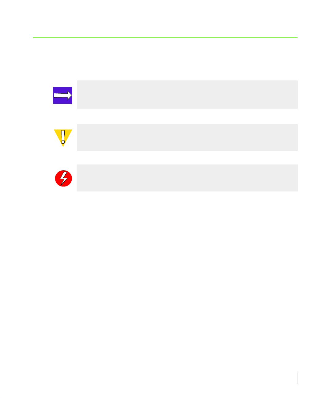
When setting up Remote Copy on the Remote Copy pair, the pair is set up in bidirectional
Remote Copy mode. In a bidirectional Remote Copy setup, both servers in the Remote Copy
pair serve as primary and backup servers in relation to one other. This relationship is illustrated
in Figure 2-1 that follows.
2.4
Remote Copy Terms and Concepts
Page 21
InForm OS Version 2.3.1 Remote Copy User’s Guide
Primary
Volume
Group X
Secondary
Volume
Group Y.r
Secondary
Volume
Group X.r
Primary
Volume
Group Y
Group X to Group X.r
Group Y to Group Y.r
InServ1
InServ2
Natural direction
of data replication
Figure 2-1. Relationship of Primary Versus Secondary Volume Groups on Primary and Backup Storage
Servers
In Figure 2-1, InServ1 and InServ2 act as both primary and backup servers. The following
relationships are established:
■ Volume Group X (the primary volume group on storage server InServ1) is copied to
storage server InServ2 and exists there as the secondary volume group Volume Group
X.r. InServ2 acts as a backup server to InServ1 (the primary server).
■ Volume Group Y (the primary volume group on storage server InServ2) is copied to
storage server InServ1 and exists there as the secondary volume group Volume Group Y.r.
InServ1 acts as a backup server to InServ2 (the primary server).
■ In Remote Copy, the storage server on which you initially created a volume group is
identified as the local or primary server. The natural direction of data replication (the copy)
originates from that server. In the previous figure, Remote Copy was set up on InServ1.
Therefore the natural direction of the copy is from InServ1 to InServ2 for Volume
Group X.
Remote Copy Terms and Concepts
2.5
Page 22

Remote Copy User’s Guide InForm OS Version 2.3.1
2.3 Remote Copy Volume Groups
Remote Copy operations are performed on groups of virtual volumes called Remote Copy
volume groups. A Remote Copy volume group is a group of volumes on the same storage
system that are logically related and for which there is a cross-volume ordering of writes.
Volume groups are used when data needs to be consistent across a group of volumes in order
for database or other applications to process data correctly.
Remote Copy uses volume groups to define a set of volumes for which applications might issue
dependent writes.
Remote Copy ensures that the data in the volumes within a group maintain write consistency.
When Remote Copy operations are started or stopped, this is done for the whole group. When
point-in-time snapshots of such volumes are created, writes to all volumes in the group are
blocked to assure a consistent point-in-time copy of the whole volume group.
2.4 Remote Copy Pairs
Remote Copy configurations are based on the relationship between a storage server pair, also
known as the Remote Copy pair. Within this pair, the primary storage server is the server that
holds the volumes that are copied to a backup server, also known as a remote storage server.
2.6
As described in N-to-1 Restrictions on page 2.43, a maximum of four primary storage servers
can use the same backup storage server. In such configurations, the backup storage server
participates in multiple pairs, one for each primary storage server. See Figure 2-4 for an
example of a configuration that uses multiple Remote Copy pairs.
NOTE: For any configuration, the backup storage server might be at the same
location as the primary storage server or servers, or it might reside at a remote
location. Disaster recovery applications often require that the backup storage
server reside at a remote location relative to the primary storage servers.
Remote Copy Volume Groups
Page 23
InForm OS Version 2.3.1 Remote Copy User’s Guide
Primary
Volume
Secondary
Volume
InServ1
InServ2
Group X
Group X.r
Secondary
Volume
Group Y.r
Primary
Vol ume
Group Y
Direction of data
replication
Group X to Group X.r
Group Y to Group Y.r
2.5 Remote Copy Configuration
As stated previously, Remote Copy configurations are based on the relationship between a pair
of InServ Storage Servers (Remote Copy pair). The storage servers in the Remote Copy pair play
multiple roles at the same time. Both storage servers can function as both the primary and
backup servers and can hold primary and secondary volume groups. This configuration is
referred to as a bidirectional Remote Copy configuration. Conversely, a Remote Copy setup
where all groups are primary on one server and all groups are secondary on the other server is
referred to as unidirectional. A combination of bidirectional (for one Remote Copy pair) and
unidirectional configurations can be used in multi-Remote Copy pair setups (N-to-1 or
1-to-N configurations). Each configuration is discussed further in the sections that follow.
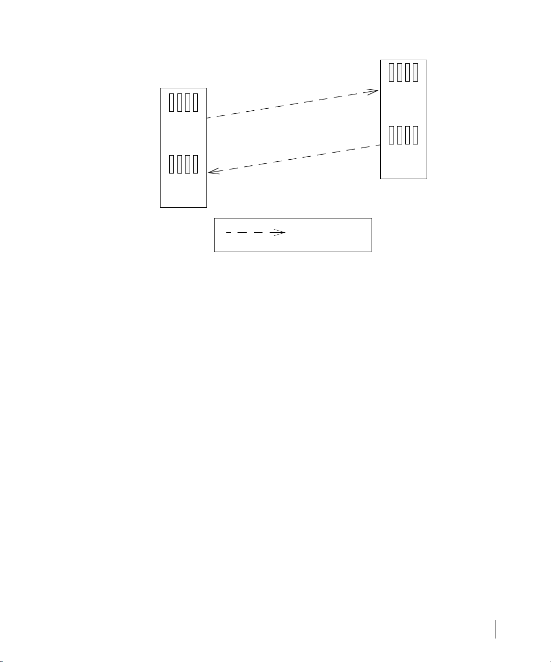
2.5.1 Bidirectional Configurations
In a bidirectional Remote Copy pair, each storage server provides backup for the other, but
only for selected volume groups. Figure 2-2 illustrates how this configuration might work with
a single Remote Copy pair.
Figure 2-2. Bidirectional Remote Copy
Remote Copy Configuration
2.7
Page 24
Remote Copy User’s Guide InForm OS Version 2.3.1
Primary
Backup
Primary
Vol ume
Secondary
Volume
Storage Server
Storage Server
Group X
Group X.r
Direction of data
replication
Primary to Secondary Group
(InServ1)
(InServ2)
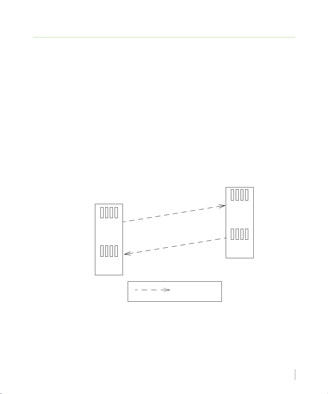
2.5.2 Unidirectional Configurations
In a unidirectional Remote Copy configuration, each storage server in the pair plays either the
role of the primary server or the backup server. In this configuration, the primary storage
server or servers holds all primary volume groups and the backup storage server holds all
secondary volume groups.
2.8
Remote Copy Configuration
Figure 2-3. Unidirectional Remote Copy
Page 25

InForm OS Version 2.3.1 Remote Copy User’s Guide
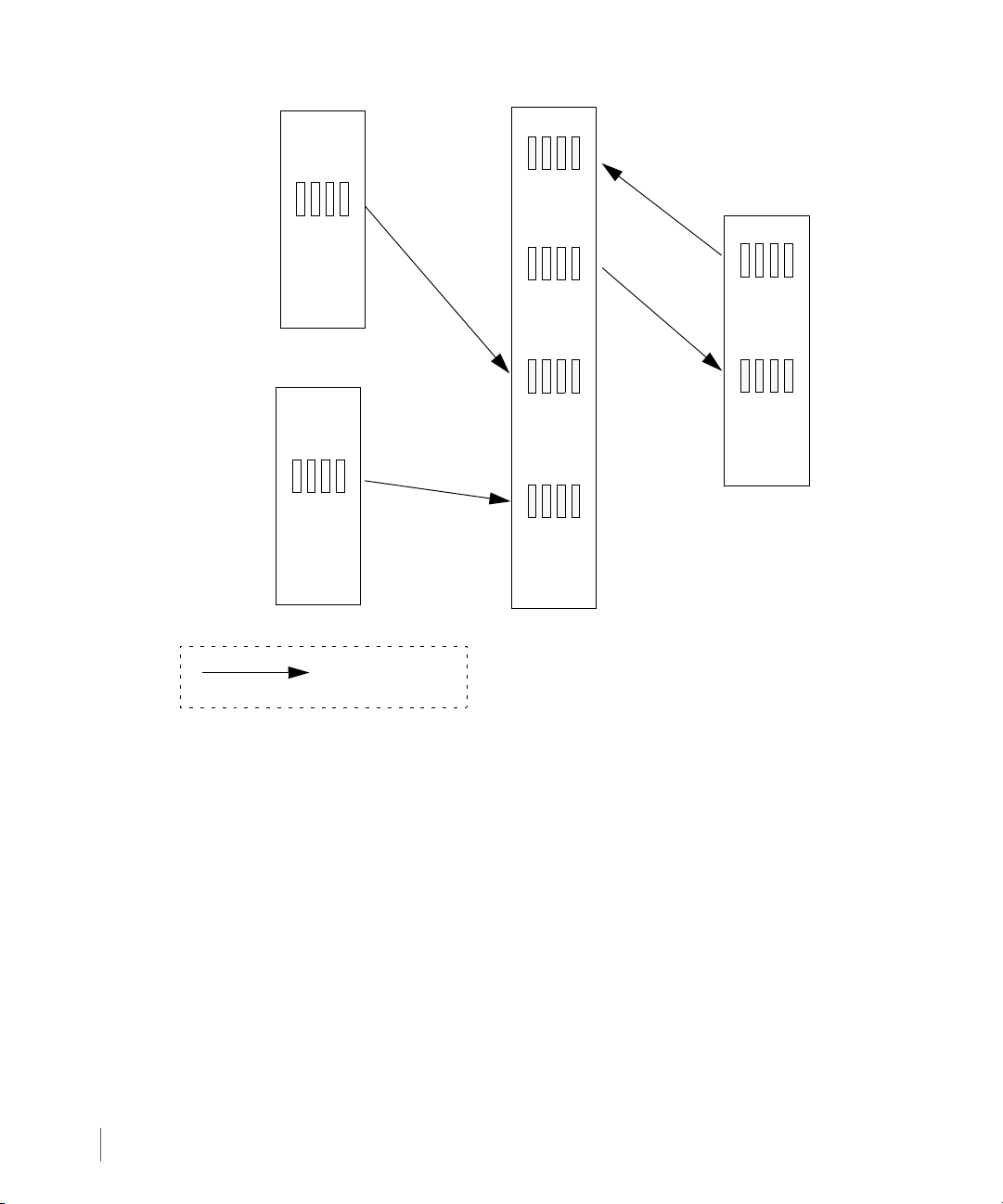
2.5.3 N-to-1 Configurations
In N-to-1 Remote Copy configurations, a maximum of four primary storage servers use the
same secondary (backup) storage server. N-to-1 Remote Copy configurations can operate in
either a combination of bidirectional (for one Remote Copy pair) and unidirectional
functionality (as shown in Figure 2-4), or in complete unidirectional functionality. In the
following figure, unidirectional Remote Copy is maintained between Remote Copy pairs
InServ1 and InServ4, and Remote Copy pairs InServ2 and InServ4. Bidirectional Remote
Copy is maintained between Remote Copy pair InServ3 and InServ4.
NOTE: In an N-to-1 Remote Copy configuration, only one link can be
bidirectional. The secondary storage server must have four or more controller
nodes.
Remote Copy Configuration
2.9
Page 26
Remote Copy User’s Guide InForm OS Version 2.3.1
Direction of data
replication
InServ1
InServ2
InServ3
InServ4
Primary
Volume
Group W
Primary
Volume
Group X
Secondary
Volume
Group W.r
Secondary
Volume
Group X.r
Primary
Volume
Group Y
Secondary
Volume
Group Y.r
Primary
Volume
Group Z
Secondary
Volume
Group Z.r
Group W to
Group W.r
Group X to
Group X.r
Group Y to
Group Y.r
Group Z to
Group Z.r
2.10
Remote Copy Configuration
Figure 2-4. N-to-1 Remote Copy
Page 27
InForm OS Version 2.3.1 Remote Copy User’s Guide
Direction of data
replication
InServ2
InServ3
InServ1
Secondary
Vol ume
Group W.r
Secondary
Vol ume
Group X.r
Primary
Vol ume
Group W
Primary
Vol ume
Group X
Secondary
Vol ume
Group Z.r
Primary
Vol ume
Group Z
Group W to
Group W.r
Group X to
Group X.r
Group Z to
Group Z.r
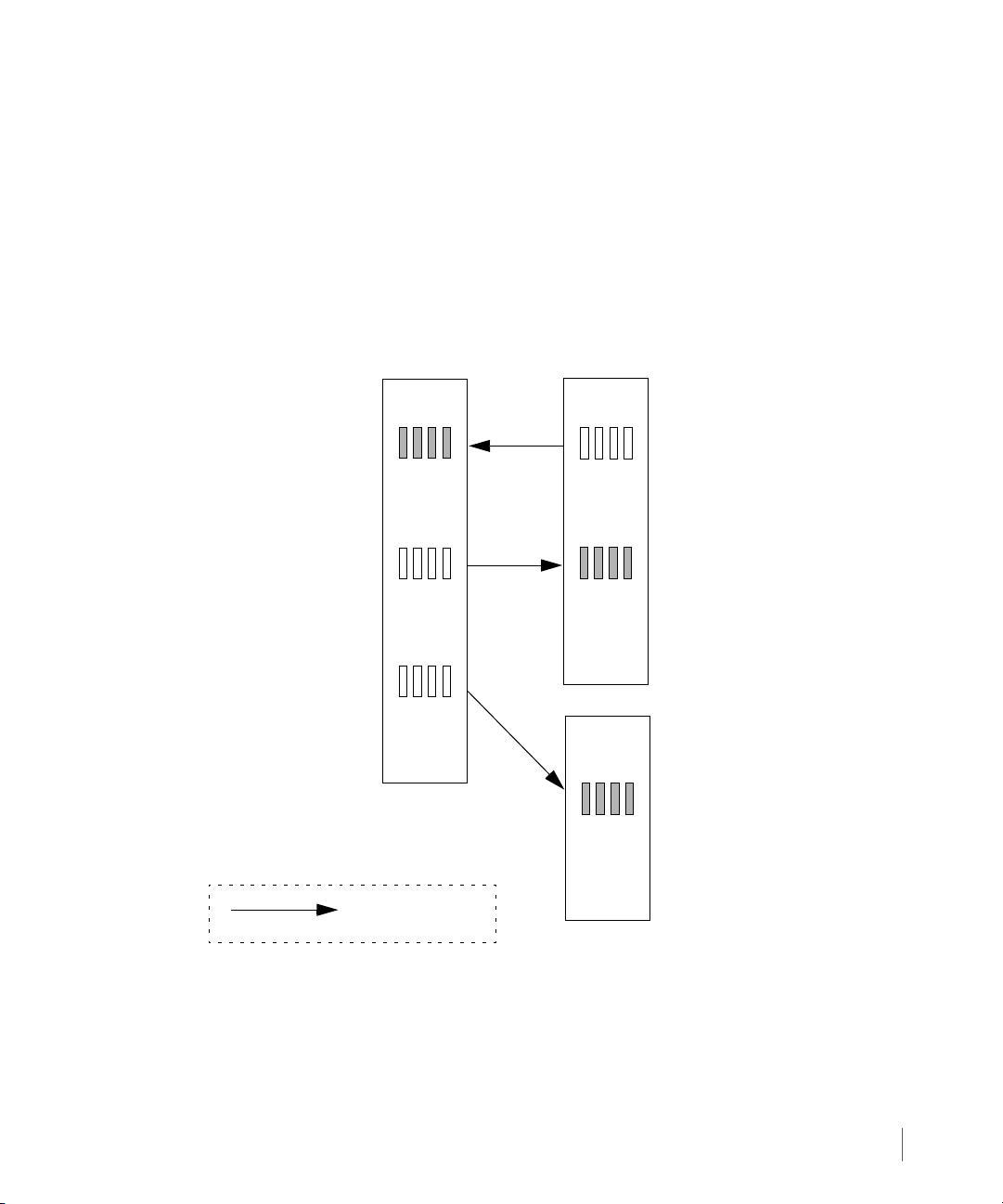
2.5.4 1-to-N Configurations
In a 1-to-N Remote Copy configuration, a single primary storage server can use multiple
InServ Storage Servers as backup servers. For the current release, a 1-to-N Remote Copy
configuration has a maximum of two secondary (backup) targets. Like N-to-1 Remote Copy
configurations, 1-to N Remote Copy configurations can operate in either a combination of
bidirectional (for one Remote Copy pair) and unidirectional functionality (as shown in
Figure 2-5), or in complete unidirectional functionality. In the following figure, unidirectional
Remote Copy is maintained between Remote Copy pairs InServ1and InServ3. Bidirectional
Remote Copy is maintained between Remote Copy pair InServ1 and InServ2.
Figure 2-5. 1-to-N Remote Copy
Remote Copy Configuration
2.11
Page 28

Remote Copy User’s Guide InForm OS Version 2.3.1
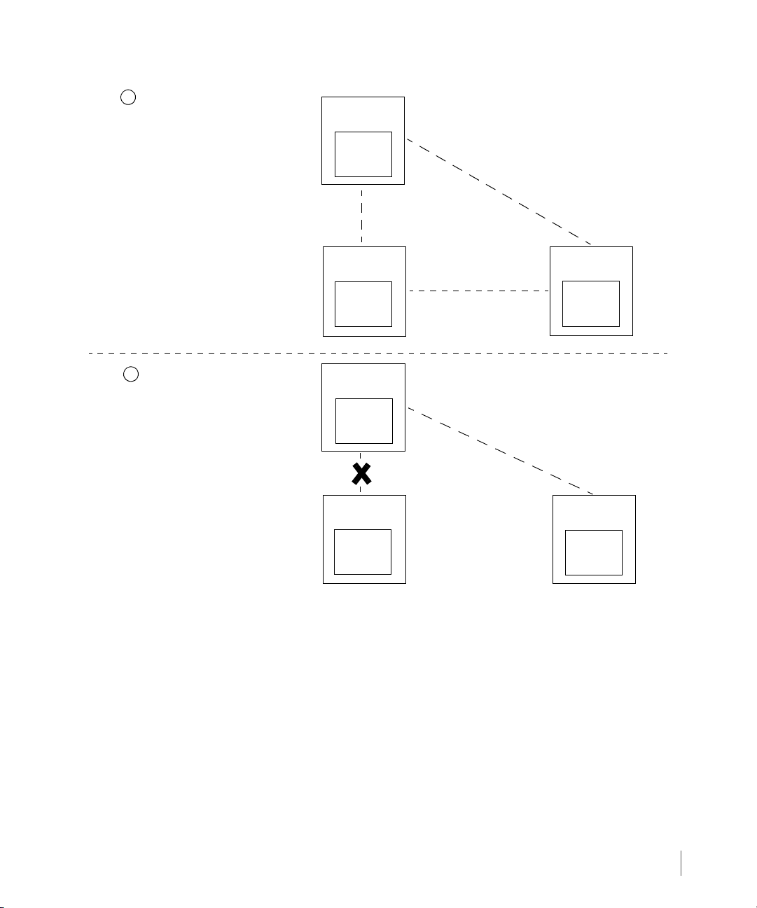
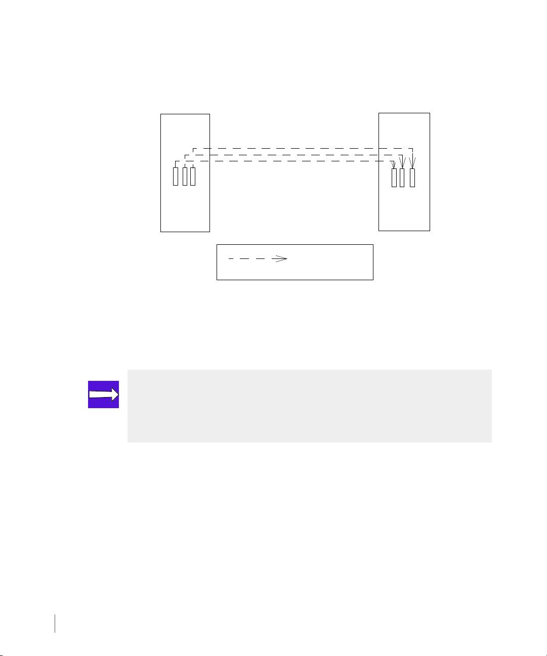
2.5.5 Synchronous Long Distance Configuration
In Synchronous Long Distance Remote Copy configurations, a single volume group is copied
directly to volumes on two other servers by admitting the volumes to groups with two targets.
Synchronous mode Remote Copy is used between the primary server and backup server that
are physically closer to each other where a high bandwidth/low latency connection is shared,
and asynchronous periodic mode Remote Copy is used between the primary server and backup
server that are physically farther apart sharing a lesser connection (see Synchronization Types
on page 2.25 for details about synchronous and asynchronous periodic modes). The
synchronous connection must be a Fibre Channel connection while the asynchronous periodic
connections can be either all Fibre Channel (over an IP network) or all IP.
In a Synchronous Long Distance Remote Copy configuration, if one backup server fails, Remote
Copy can still continue between the primary server and the second backup server. As shown in
Figure 2-6, when the backup server InServ2 fails, Remote Copy in asynchronous periodic mode
still continues between the primary server InServ1 and second backup server InServ3.
Conversely, if InServ3 failed, Remote Copy in synchronous mode would still continue between
InServ1 and InServ2.
NOTE: Synchronous Long Distance Remote Copy links cannot be bidirectional.
2.12
Remote Copy Configuration
Page 29
InForm OS Version 2.3.1 Remote Copy User’s Guide
InServ1
(primary server)
InServ2
(backup server)
InServ3
(backup server)
Synchronous
Mode
Prior to InServ2 Failure
1
2
InServ2 Failure
InServ2
(backup server)
InServ3
(backup server)
Primary
Volum e
Group A
Secondary
Volum e
Group A
1
Secondary
Volum e
Group A
2
Secondary
Volum e
Group A
1
Secondary
Volum e
Group A
2
InServ1
(primary server)
Primary
Volum e
Group A
Asynchronous
ModePeriodic
Asynchronous
ModePeriodic
(standby link)
Figure 2-6. Synchronous Long Distance Remote Copy - One Backup Server Failure
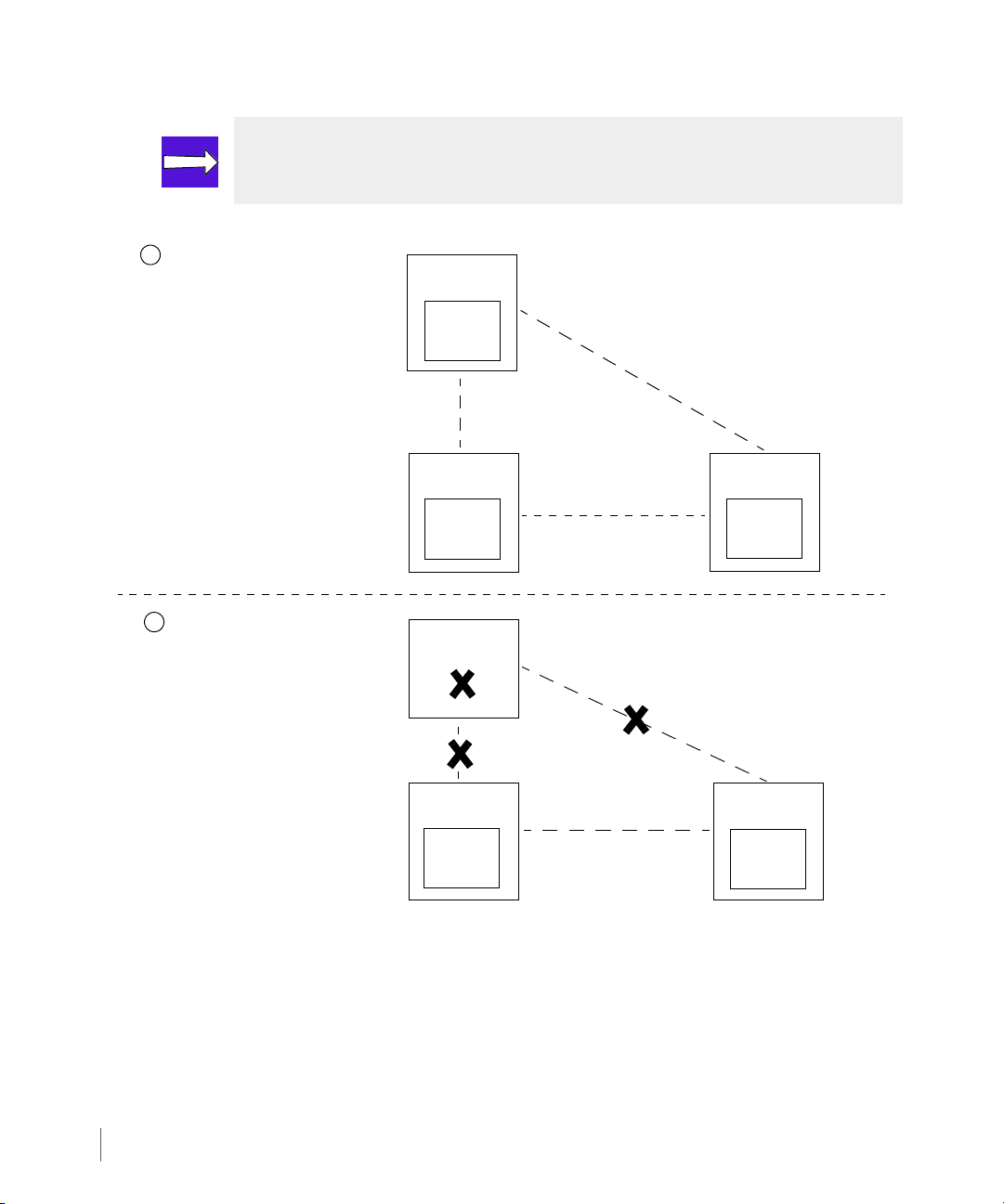
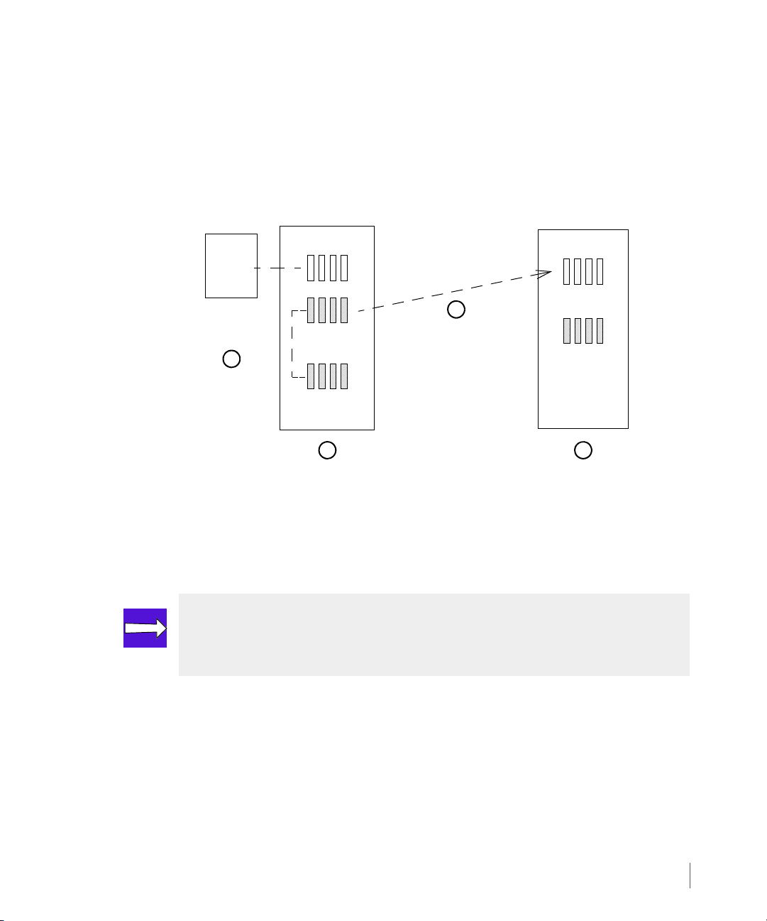
Upon restoration of InServ2, data is transferred from InServ1 to InServ2 and synchronous
mode Remote Copy is restored between InServ1 and InServ2.
In the event of an primary server failure, one of the backup servers (typically the backup server
sharing a synchronous Remote Copy connection with the primary server) assumes the role of
the primary server and the second backup server then serves as the backup of the new primary
system. The volume on the new primary server is updated periodically on the backup server. As
shown in Figure 2-7, when the primary server InServ1 goes down, InServ2 becomes the
primary server and InServ3 becomes the backup server to InServ2.
Remote Copy Configuration
2.13
Page 30
Remote Copy User’s Guide InForm OS Version 2.3.1
InServ1
(primary server)
InServ2
(backup server)
InServ3
(backup server)
Synchronous
Mode
Prior to InServ1 Failure
1
2
InServ1 Failure
InServ1
(failed)
InServ2
(primary server)
InServ3
(backup server)
Primary
Volum e
Group A
Secondary
Volum e
Group A
1
Secondary
Volum e
Group A
2
Primary
Volum e
Group A
Secondary
Volum e
Group A
Asynchronous
ModePeriodic
Asynchronous
ModePeriodic
(standby link)
NOTE: Either backup server can be set up to assume the role of the primary server
in the event of failover. See Chapter 3, Remote Copy Setup for information.
2.14
Figure 2-7. Synchronous Long Distance Remote Copy - Primary Server Failure
Upon restoration of InServ1:
■ Data is transferred from InServ2 to InServ1, and InServ1 is restored to the primary server.
■ InServ2 and InServ3 are restored as backup servers.
■ Synchronous mode Remote Copy is restored between InServ1 and InServ2.
Remote Copy Configuration
Page 31

InForm OS Version 2.3.1 Remote Copy User’s Guide
■ Asynchronous periodic mode Remote Copy is restored between InServ1 and InServ3.
Additionally, Synchronous Long Distance Remote Copy can also be used for data migration
when replacing an InServ Storage Server in an existing Remote Copy configuration (see
Appendix C, Example Setup and Disaster Recovery).
2.6 Remote Copy Targets
While using Remote Copy, the relationship between primary and backup storage servers is not
always static. For example, Appendix C, Example Setup and Disaster Recovery illustrates
disaster recovery scenarios that require you to temporarily reverse the primary and backup
roles played by the storage servers.
NOTE: For more information about how the relationship between storage servers
can be reversed so that the primary storage server becomes the backup and vice
versa, see Remote Copy Operation on page 2.20 and Appendix C, Example Setup
and Disaster Recovery.
In addition, as described in Remote Copy Configuration on page 2.7, using bidirectional
Remote Copy can complicate the distinction between primary and backup storage servers
because each storage server plays both roles.
Because the relationship between primary and backup storage servers is not always simple,
Remote Copy uses the term Remote Copy target system, to refer to the other storage server in
a Remote Copy pair. For example, in Figure 2-2 and Figure 2-3, the target system for InServ1
is InServ2 and vice versa.
2.6.1 Target Definitions
As part of the Remote Copy setup process (described in detail in Chapter 3, Remote Copy
Setup), you must create target definitions on each Remote Copy system. The target definitions
are descriptions that exist on one system in order to identify a Remote Copy system. In short,
the InServ Storage Servers in the Remote Copy pair are each defined as targets, relative to each
other, for Remote Copy operations.
Figure 2-8 illustrates how target definitions might work with a bidirectional pair that has two
primary volume groups.
Remote Copy Targets
2.15
Page 32

Remote Copy User’s Guide InForm OS Version 2.3.1
Primary
Vol ume
Secondary
Volume
InServ1
InServ2
Group X
Group X.r
Secondary
Volume
Group Y.r
Primary
Volume
Group Y
Group X
Targ et: In Se rv2
Group X.r
Target: InServ1
Group Y.r
Target: In Serv2
Group Y
Target: In Serv1
Direction of data
replication
Figure 2-8. Target Definitions (Single Pair, Bidirectional)
In the previous figure,
■ the Remote Copy target system is InServ2 for the Volume Group X on InServ1.
■ the Remote Copy target system is InServ1 for the replicated volume group Volume Group
X.r on InServ2.
2.16
■ the Remote Copy target system is InServ1 for the Volume Group Y on InServ2.
■ the Remote Copy target system is InServ2 for the replicated volume group Volume Group
■ the target definitions are simply the names of the storage servers (InServ1 and InServ2) in
The relationship between target definitions and the server pairs described previously holds
true for all valid Remote Copy configurations (bidirectional, unidirectional, N-to-1, 1-to-N, and
synchronous long distance). The server on which the volume groups originate (the primary
server), defines the target as its backup server.
Remote Copy Targets
Y.r on InServ1.
relation to each other.
NOTE: The target name is not required to match the system name.
Page 33

InForm OS Version 2.3.1 Remote Copy User’s Guide
(Primary)
(Backup)
Node x
Node y
Node x
Node y
Node x
Node y
Node x
Node y
InServ1
InServ2
2.7 Remote Copy Links
Remote copy links are divided into two main types, sending links and receiving links. Sending
links are created manually during the Remote Copy setup by using the
or admitrcopylink
have sending links configured.
2.7.1 Sending Links
Sending links are used to transmit data to a Remote Copy target system, and are associated
with target definitions, with one set of links per defined target.
For each configured IP interface, the Remote Copy link uses TCP port 5785 to transmit data and
commands from the primary server to the backup server.
It is only possible to configure one sending link per target definition per node. For example,
either of the configurations illustrated in Figure 2-9 are supported, but Remote Copy does not
support both of these connection methods at the same time:
commands. Receiving links are automatically created on all nodes that
creatercopytarget
Figure 2-9. Sending Link Connection Methods
All examples in this guide use the connection method as illustrated in the previous figure.
When setting up Remote Copy links between a Remote Copy pair, you must create one set of
sending links on the primary storage server and one set of sending links on the backup storage
server (Figure 2-10). Additional targets require the creation of additional link sets. These links
are created as part of the Remote Copy setup described in Setting Up Remote Copy on
page 3.16.
Remote Copy Links
2.17
Page 34

Remote Copy User’s Guide InForm OS Version 2.3.1
Node 6 Node 7
Network
InServ1
Node 2 Node 3
InServ2
172.16.1.12
172.16.2.12
172.16.1.11
172.16.2.11
172.16.1.11
172.16.2.11
172.16.2.12
172.16.1.12
Links to
Target:
Links to
Target:
InServ2
InServ1
Figure 2-10. Sending Links for a Remote Copy Pair
2.7.2 Receiving Links
2.18
While sending links are used to transmit data, receiving links are used to listen. The receiving
links read Remote Copy data and commands and send them to the appropriate Remote Copy
process for processing. Unlike sending links, there is only a single link of a given type per node,
regardless of the number of sending links of that type.
2.8 Remote Copy Connections
When using Remote Copy for disaster recovery, the backup storage server should reside at a
remote site some distance from the primary server(s) so that the two sites are unlikely to be
affected by the same disaster. The latency of Remote Copy writes increases with distance.
Storage servers in a Remote Copy pair are connected through a dedicated link or through a
network (see Figure 2-16 on page 2.41). You should choose a specific topology based on
several factors, including the distance between the servers and the required bandwidth of the
connection.
Remote Copy Connections
Page 35

InForm OS Version 2.3.1 Remote Copy User’s Guide
NOTE: Remote Copy over IP (RCIP) configurations can fully utilize both 1Gbps
links during the synchronization process. If lower throughput networks are used,
throughput between systems running Remote Copy might be capped by the
network.
Connections between servers in the same room could be provided as direct Gigabit Ethernet
(GigE) links or through GigE switches, or through Fibre Channel networks. Longer distances
require other topologies.
NOTE: A GigE-capable interface is required for RCIP configurations.
NOTE: The 3PAR Remote Copy solution includes two separate network
connections between storage servers. The Remote Copy software balances the
load and manages the failover between these connections. For optimal
availability, the two connections should be connected to separate network
equipment.
More than one link must be used to connect storage servers to maintain availability. When
there are multiple physical links between the storage servers, Remote Copy uses all the
available links to transmit data in parallel.
2.8.1 IP Networks
CAUTION: When configuring the GigE interfaces, the GigE interface and the
management Ethernet port of an InServ Storage Server controller node should be
on different IP subnets. If they are configured on the same subnet, Remote Copy
packets might go over the management port and would not be available to the
Remote Copy software.
Before configuring Remote Copy, you need a good understanding of the IP network that will
be used to connect the storage servers. When more than one storage server is used at the same
location, it is possible that they are in the same subnet. However, it is much more likely that the
Remote Copy Connections
2.19
Page 36

Remote Copy User’s Guide InForm OS Version 2.3.1
storage servers in the proposed configuration are separated by a large distance and have been
placed on different IP subnets. If the storage servers are on different subnets, each storage
server must be connected to a gateway router or switch on that subnet and there must be an
IP cloud between their gateways.
2.8.2 Fibre Channel Networks
Remote Copy over Fibre Channel is supported on storage servers communicating over Fibre
Channel Storage Area Networks (FC SAN). Each storage server should have a pair of Host Bus
Adapters (HBAs) installed. This HBA pair must be dedicated to Remote Copy. The HBA pair is
required for load sharing and fault tolerance. The HBAs in each storage server connect these
systems through FC SAN using Fibre Channel cable connections.
Before configuring Remote Copy, you need a good understanding of the FC SAN that will be
used to connect the storage servers. They must be configured to be in the same FC SAN and
Zone.
2.8.3 Fibre Channel over IP Networks
NOTE: RCFC over IP networks is only allowed for Remote Copy in asynchronous
periodic mode.
2.20
Remote Copy over Fibre Channel is also supported on storage servers communicating over an
IP network. In this type of setup, the primary and backup InServ Storage Servers use Fibre
Channel connections, which pass through routers to cross an IP network.
2.9 Remote Copy Operation
As described previously in Remote Copy Volume Groups on page 2.6, in order to maintain
write consistency, Remote Copy operations are performed on groups of virtual volumes called
Remote Copy volume groups.
Another use of volume groups with Remote Copy is to simplify administration. For example,
the number of commands that need to be executed can be reduced by using volume groups. A
single
start/stop/setrcopygroup command applies to all volumes in a group. This can
reduce the number of CLI commands that need to be run to configure and operate Remote
Copy. Even when the volumes do not need write consistency, if the volumes are added to a
single group, Remote Copy treats them as related volumes.
Remote Copy Operation
Page 37

InForm OS Version 2.3.1 Remote Copy User’s Guide
InServ1
InServ2
Volume Group X
Volume Group X.r
(Primary)
(Secondary)
AABBC
C
Volume Group Y.r
Volume Group Y
(Secondary)
(Primary)
DDEEF
F
Group X
Target: InServ2
Group X.r Target: InServ1
Group Y.r
Target: InServ2
Group Y
Targ et: In Se rv1
Direction of data
replication
NOTE: Although the benefits of using volume groups are considerable, one
drawback is that the I/O to all volumes in the group is blocked while taking
snapshots. If the number of volumes in the group is very large (the current
supported limit is 100 volumes per group), the blocking of the I/O might result in
some host writes timing out.
For bidirectional configurations, both storage servers can hold primary and secondary volume
groups. For a bidirectional Remote Copy pair, each storage server provides backup for the
other, but only for the selected volume groups (Figure 2-11).
Figure 2-11. Mapping of Volumes Between a Bidirectional Remote Copy Pair
Remote Copy Operation
2.21
Page 38
Remote Copy User’s Guide InForm OS Version 2.3.1
Volume Grou p
Volume Group
(Primary)
(Backup)
(Primary)
(Secondary)
InServ1
InServ2
AABBC
C
Target: InServ2
InServ1
Target: InServ1
InServ2
Direction of data
replication
For unidirectional Remote Copy, each virtual volume in a Remote Copy group on the primary
server is mapped to a virtual volume in a corresponding secondary group on the backup
storage server (Figure 2-12).
Figure 2-12. Mapping of Volumes Between Primary and Backup Storage Server
In both cases, any primary volume can be mapped to any secondary volume that belongs to the
corresponding Remote Copy group on the target system, with the restriction that the
secondary volume be the same size as the primary volume.
2.22
NOTE: All volumes used with Remote Copy must be Thinly Provisioned Virtual
Volumes (TPVVs) with snapshot space., or fully provisioned virtual volumes as
discussed in Remote Copy and Thin Provisioning on page 2.33. However, snapshot
volumes in Remote Copy groups are not supported.
2.9.1 Volume Group Modes
There are two modes used by Remote Copy volume groups: synchronous and asynchronous
periodic.
■ Synchronous mode volume groups stay synchronized at all times. See Synchronous Mode on
page 2.23 for a detailed description of this Remote Copy mode.
■ Asynchronous periodic mode volume groups undergo resynchronization periodically, either
at a scheduled interval or when resynchronization is manually initiated. For a detailed
description of this Remote Copy mode, see Asynchronous Periodic Mode on page 2.24.
Remote Copy Operation
Page 39

InForm OS Version 2.3.1 Remote Copy User’s Guide
Primary
Backup
Storage Server
Storage Server
Host
Write request
Write request forwarded
Data written to cache
on two nodes
Data written to cache
Backup acknowledges primary
1
2
3
4
5
6
Primary acknowledges host
on two nodes
2.9.1.1 Synchronous Mode
In synchronous mode, a host-initiated write is performed on both the primary and the backup
storage servers before acknowledging the host write. On the primary storage server, data is
written to the caches of two nodes. This redundancy is in place in case one node fails before
the write can be copied to a disk. Concurrently, the write request is sent to the backup storage
server through a communication link. The backup storage server writes the same information
into its cache (again, on two nodes) and then sends an acknowledgement to the primary
system. The host write is acknowledged after the active cache update completes and the
backup acknowledgement is received (Figure 2-13).
Figure 2-13. Synchronous Mode Remote Copy
Synchronous copying keeps the primary and backup storage servers synchronized at all times
and provides a higher level of data integrity compared to the asynchronous periodic mode
(explained in the following sections). No acknowledged I/O is lost even if the primary storage
server, the backup storage server, or the communication links go down. In the case of a disaster
affecting the primary storage server, the copy stored on the backup storage server at the
remote site is an exact replica and can be immediately used to continue the application.
Remote Copy Operation
2.23
Page 40

Remote Copy User’s Guide InForm OS Version 2.3.1
Primary
Backup
Storage Server
Storage Server
Host
Write request
Data written to caches
on two nodes
data written to cache
1
2
3
Primary acknowledges host
Scheduled or manual resynchronization
Only most recent data copied over
Only most recent
on the nodes
2.9.1.1.1 Latency
Synchronous mode adds more latency to the write because the I/O needs to be sent to the
backup server over the IP network or SAN and then an acknowledgement must be received
from the backup server before acknowledging the host. As the distance between the primary
and backup storage servers increases, the latency also increases. For example, a one-way
distance of 100 miles adds approximately two milliseconds to the write latency. Even with the
primary and backup storage systems side-by-side, Remote Copy running in synchronous mode
adds some latency to a host write.
2.9.1.2 Asynchronous Periodic Mode
In the asynchronous periodic mode, host writes are performed only on the primary server and
the host write is acknowledged as soon as the data is written into cache on the primary storage
server (Figure 2-14).
2.24
Remote Copy Operation
The primary and backup volumes are resynchronized periodically, for example, when
Figure 2-14. Remote Copy in Asynchronous Periodic Mode
scheduled or when resynchronization is manually initiated through the syncrcopy command.
If, between two resynchronizations, an area of the volume is written to multiple times, only
the last write needs to be sent over to the other storage server. Therefore, when using Remote
Copy in asynchronous periodic mode, less data is transferred relative to the synchronous mode.
Page 41

InForm OS Version 2.3.1 Remote Copy User’s Guide
2.9.2 Synchronization Types
There are two types of synchronizations that are performed on volume groups: full
synchronizations and resynchronizations.
A full synchronization copies the primary volume in its entirety, whereas a resynchronization
copies only what has changed after the previously completed synchronization. A new volume
group always requires a full synchronization at first, whether it is an asynchronous periodic
volume group or a synchronous volume group (see Volume Group Modes on page 2.22 to
understand the difference).
When a synchronization is initiated, with the exception of the initial synchronization,
snapshots are created on the backup storage server. This stage is required to ensure that the
backup system maintains a valid point-in-time copy at all times. The system must always
maintain a valid point-in-time copy because a failed synchronization attempt could leave the
base volumes in an inconsistent state.
2.9.2.1 Asynchronous Periodic Mode Volume Groups
For the asynchronous periodic mode volume groups, after the snapshots are created on the
backup storage server, all volumes in the primary volume group (on the primary storage server)
accept new writes, but hold the acknowledgement. While new writes are held, the primary
system creates snapshots of all volumes within the group. After creating these snapshots, the
system allows I/O to resume and acknowledges any writes that were held (Figure 2-15).
NOTE: Any writes sent from the host are accepted, but not committed or
acknowledged until after the snapshots are completed. This is to ensure that the
host will not see any I/O failure.
Remote Copy Operation
2.25
Page 42

Remote Copy User’s Guide InForm OS Version 2.3.1
New writes blocked on Primary
Primary
Storage Server
2
3
Snapshots created
for all Volumes in
4
I/O allowed to resume on Primary Group
1
Snapshots Created
For All Volumes
Backup
Storage Server
Primary
Snapshots
Vol um e Grou p
Secondary
Volume Group
Snapshots
the Primary Group
in Secondary Group
Primary
Storage Server
Primary
Snapshots
Vol um e Grou p
Backup
Storage Server
Secondary
Volume Group
Complete data for each volume
copied over individually
from the snapshot to the
corresponding Secondary Volume
Host
I/O might continue
while synchronization
takes place
Figure 2-15. Snapshot Creation Prior to Resynchronization (Asynchronous Periodic)
After the system has successfully created all snapshots, the synchronization process can begin.
The synchronizations are done individually for each volume. If the primary volume has never
been synchronized (or if no valid resynchronization snapshot exists), the system performs a full
synchronization. In a full synchronization, all data on the snapshot is transmitted to the
backup volume. After the synchronization is complete, the active snapshot is saved in order to
perform a fast resynchronization at a later point in time (Figure 2-16).
2.26
Remote Copy Operation
Figure 2-16. Full Synchronization Using Snapshots of Primary Volumes (Asynchronous Periodic)
Page 43
InForm OS Version 2.3.1 Remote Copy User’s Guide
Primary
Storage Server
Primary
Most Recent
Volume Grou p
Backup
Storage Server
Secondary
Volume Group
Most Recent
Host
I/O might continue
while synchronization
takes place
Snapshots
Snapshots
Previous
(Resynchronization)
Snapshots
Primary system
most recent and
previous snapshots
1
2
compares
Only changes for each volume
are copied over individually
from the most recent snapshot
to the corresponding backup
volume
3
Snapshots on
backup server
are deleted
4
Previous snapshots
on primary server are
deleted and the most
recent snapshots become
resynchronization snapshots
If the primary volume has been previously synchronized, and a resynchronization snapshot
exists, then a fast resynchronization is performed. The two snapshots (the resynchronization
snapshot and the current synchronization snapshot) are compared to determine what changes
have occurred between the creation of each snapshot. The system transmits only these changes
to the secondary volume (Figure 2-17).
After the entire volume group has been synchronized with the secondary group, the snapshots
that were created on the backup system are deleted, as the base volumes now represent a
valid point-in-time copy. After a resynchronization is complete, the old resynchronization
snapshot is deleted, and the newer snapshot is saved for future resynchronization.
Figure 2-17. Fast Resynchronization Using Resynchronization Snapshots
NOTE: Because of the use of multiple snapshots, adequate virtual volume space
must be available. See Remote Copy and Thin Provisioning on page 2.33 for
important information about space allocation and deleted snapshots.
Remote Copy Operation
2.27
Page 44

Remote Copy User’s Guide InForm OS Version 2.3.1
2.9.2.2 Synchronous Mode Volume Groups
Rather than creating snapshots on the primary volume group for synchronous mode volume
groups, the I/O is taken directly from the base volume when synchronization begins.
Synchronous mode volume groups resynchronize automatically when they are stopped and
restarted. When stopped, the system takes snapshots that are used for resynchronization.
2.9.3 Resynchronization Period
In order for resynchronizations to be performed automatically with asynchronous periodic
mode volume groups, you must configure the synchronization period for the volume group.
There is no default synchronization period; it must be set using the
command as described in Setting Remote Copy Volume Group Policies on page 4.4. This
command can be issued any time after the group is created, even after Remote Copy
operations have started for the group. When the resynchronization period is set for the
primary volume group, by default it is mirrored to the secondary.
CAUTION: The resynchronization period should be set to allow sufficient time for
the group to complete synchronizing. If too little time is specified, it is possible
that the group will continuously synchronize.
setrcopygroup
2.28
The length of the synchronization period should be chosen based on the tolerance for data
concurrency (the amount of delay that can be tolerated in updating the backup storage
server).
The minimum synchronization period supported by Remote Copy is five minutes. Because of
the overhead involved in creating and deleting snapshots when starting and stopping a
resynchronization, the period you select should be long enough to allow the previous
resynchronization to complete. If a resynchronization is still taking place before the next
scheduled resynchronization, the new resynchronization starts briefly after the previous
resynchronization has completed. Future resynchronizations use the new schedule, starting
one period after the delayed resynchronization took place.
Remote Copy Operation
Page 45

InForm OS Version 2.3.1 Remote Copy User’s Guide
2.9.4 Manual Resynchronization
Additional manual resynchronizations might be initiated for asynchronous periodic or
synchronous mode volume groups using the
command, only the changes to the primary volume group after the last resynchronization
point are sent over the network to the backup storage server. Use the
command to force a synchronous mode volume group to synchronize. This causes a full
synchronization.
NOTE: To schedule a synchronization to take place at a particular time (for
example, 12:00 pm daily), use a host-based script and manual resynchronization.
syncrcopy command. When using this
syncrcopy -ovrd
2.9.5 Concurrent Synchronization Limits
To limit the performance impact of Remote Copy on the rest of the InServ Storage Server, the
number of volumes that are concurrently synchronizing is limited to 20 volumes. This limit is
not user-configurable and applies to the initial synchronization as well as subsequent
resynchronizations for the synchronous as well as the asynchronous periodic groups. See
Synchronous Mode on page 2.23 and Asynchronous Periodic Mode on page 2.24 for additional
information about synchronous and asynchronous periodic groups.
For example, if there are 30 volumes in the asynchronous periodic mode that are being
resynchronized, you might notice that 10 volumes do not start synchronizing until some of the
first 20 complete. This can be seen by monitoring the
command output (see showrcopy on page B.57 for example output).
NOTE: For complete details on the showrcopy command, including valid
synchronization, link, and group states, see showrcopy on page B.57.
To ensure volume group consistency, all snapshots for the asynchronous periodic group are
maintained on the secondary server until all of the volumes in that group have completed
synchronization.
SyncStatus column of the showrcopy
Remote Copy Operation
2.29
Page 46

Remote Copy User’s Guide InForm OS Version 2.3.1
2.9.6 Throughput Limiting Option
For asynchronous periodic mode Remote Copy (see Asynchronous Periodic Mode on
page 2.24), it might be useful to use the throughput limiting option when setting up links over
leased lines. This option limits the maximum throughput that Remote Copy will utilize for a
link. This is useful, for example, if the leased line charges are based on the bit rate utilized. If
this option is not used, Remote Copy attempts to send data as fast as it can on both links. If the
limit is set, the data is metered and sent out at a rate less than or equal to the set limit. For
instructions on setting this limit, see Limiting Throughput on page 4.10.
2.9.7 Role Reversal
While using Remote Copy, it is possible to reverse the roles of the volume groups. By reversing
roles, the primary becomes the backup and vice versa. To correct the reversal, you must change
the roles once again. See Reversing Target Designations on page 4.2 for specific instructions on
role reversal. Error Handling on page 2.35 also discusses role reversal.
2.10 Remote Copy and 3PAR Virtual Domains
2.30
NOTE: 3PAR Virtual Domains requires a 3PAR Virtual Domains license. For
additional information about the license, see the 3PAR InForm OS Concepts
Manual.
Remote Copy checks for 3PAR Virtual Domains (domains) on the remote system to ensure the
virtual volume is mirrored to the same domain name as the local domain name. The domain
needs to be called a correct domain name. See the 3PAR InForm OS Concepts Guide for
detailed information about domains, and see the 3PAR InForm OS CLI Administrator’s Manual
for instructions on setting up domains.
Remote Copy and 3PAR Virtual Domains
Page 47

InForm OS Version 2.3.1 Remote Copy User’s Guide
2.11 Use of Virtual Copy Snapshots
Remote Copy uses virtual copy snapshots (point-in-time virtual copies) of a virtual volume to
minimize the amount of data that needs to be sent over the network to resynchronize volumes
that were previously synchronized. There are several scenarios where snapshots are used.
2.11.1 In Synchronous Mode
In synchronous mode, a snapshot is created only under error or recovery situations or when a
group is manually stopped. If the backup storage server fails, or all communication links to the
backup server fail, the primary storage server stops the replication of all volume groups. It also
takes snapshots of all volumes that were completely synchronized. If a volume was still
undergoing the initial full synchronization when the failure happened, a snapshot is not taken
of that volume. That volume fully synchronizes when Remote Copy is restarted.
When the backup storage server comes back up, Remote Copy must be manually restarted
using the
policy is in use (see Setting Remote Copy Volume Group Policies on page 4.4). When restarted,
Remote Copy first looks for a valid resynchronization snapshot for a volume. If the
resynchronization snapshot exists, Remote Copy resynchronizes the secondary volume by
sending only the differences between that snapshot and the current data in the primary base
volume. But before this resynchronization is started, the system takes snapshots of all the
secondary volumes that were previously synchronized. While the resynchronization is taking
place, the state of the secondary volume becomes
volume is not in a consistent state because the updates are written by location order rather
than by time order. When the resynchronization completes, the snapshots on the primary and
the backup servers are deleted.
startrcopygroup command for all volume groups, unless the auto_recover
syncing. During that time, the secondary
NOTE: See Remote Copy and Thin Provisioning on page 2.33 for important
information about space allocation and deleted snapshots.
If the primary server fails during the resynchronization, the secondary base volumes are left in
an inconsistent state, but the snapshots of the secondary volumes are left behind. When the
primary server comes back, the next resynchronization brings the secondary volumes back in
synchronization with the primary volumes.
Use of Virtual Copy Snapshots
2.31
Page 48

Remote Copy User’s Guide InForm OS Version 2.3.1
If the primary server fails during a resynchronization and the backup server needs to be used
to access data, it is necessary to issue failover commands (such as those promoting the
snapshots to the base volumes using the
If, during disaster recovery or as part of a planned role-reversal, the backup storage server is
converted to a primary storage server, a snapshot is also taken on that server. This snapshot is
used to resynchronize the former primary storage server (now converted to backup) after the
former primary server and the links are brought back up and the Remote Copy operations are
resumed. To see an example disaster recovery scenario that illustrates this process, see
Appendix C, Example Setup and Disaster Recovery.
promotesv command) before reversing the targets.
2.11.2 In Asynchronous Periodic Mode
In asynchronous periodic mode, a snapshot is created as part of the normal storage system
operation. Snapshots are used to locate the data written between two synchronizations.
During the initial synchronization, a snapshot is taken of the primary volume and the data in
that snapshot is sent over to initialize the secondary volume. Later, at the next scheduled
resynchronization time or whenever the
taken of the secondary and primary volumes. The differences between the old primary
snapshot and the new primary snapshot are sent over to resynchronize the secondary base
volume.
syncrcopy command is issued, new snapshots are
2.32
Just as in synchronous mode, the secondary base volume is not consistent while the
resynchronization is taking place. If the primary server fails during the resynchronization, the
snapshot taken on the backup server is used to recover the consistent state prior to the
beginning of the resync operation. Such recovery is accomplished by automatically promoting
the snapshot to the base volume, an operation whose duration is proportional to the amount
of data changed during the failed resynchronization. If some of the volumes in the group fail
during the synchronization and others succeed, only the failed snapshots on the secondary
server are automatically promoted. The successful synchronizations are not.
After the resynchronization operation completes successfully, the secondary snapshot and the
old primary snapshot are removed. Now the base volume on the backup storage server
matches the new snapshot on the primary storage server. The new primary snapshot then
becomes available for use in the next resynchronization operation.
If, during disaster recovery or as part of a planned role-reversal, the backup storage server is
converted to a primary storage server, a snapshot is also taken on the backup storage server.
This snapshot is used to resynchronize the former primary storage server (now converted to
the backup) after the former primary server and the links are brought back up and the Remote
Copy operations are resumed. When a primary group changes to a secondary group, the most
Use of Virtual Copy Snapshots
Page 49

InForm OS Version 2.3.1 Remote Copy User’s Guide
recent snapshot is promoted. To see an example disaster recovery scenario that illustrates this
process, see Appendix C, Example Setup and Disaster Recovery.
2.12 Remote Copy and Thin Provisioning
Remote Copy makes extensive use of point-in-time snapshots. The main use of these snapshots
is to keep track of the updates to the primary volume when the data is not being sent to the
secondary volume over the communication links. The amount of snapshot space that is
required depends on the kind of replication being used. For example, if a volume’s snapshot
space is insufficient and a Remote Copy snapshot becomes stale as a result, a full
resynchronization might be needed to bring the primary and secondary volumes back in
synchronization. For this reason, Remote Copy should only be used with virtual volumes that
automatically draw space from a Common Provisioning Group (CPG); a user-created storage
pool available to all volumes associated with it. For instructions on taking existing virtual
volumes and associating them with a CPG so that they might be used with Remote Copy, see
Converting Standard Virtual Volumes on page 4.8.
There are two types of virtual volumes, which draw spaces from CPGs that can be used with
Remote Copy: Thinly Provisioned Virtual Volumes (TPVVs) and fully provisioned virtual
volumes. For TPVVs, all data and snapshot space is allocated on demand from a CPG. For fully
provisioned virtual volumes, only the snapshot space is allocated on demand from the CPG.
2.12.1 Snapshots and Common Provisioning Groups
A Common Provisioning Group (CPG) is a virtual pool of logical disks that allows multiple
volumes to share the CPG's resources and allocate space on demand. However, CPGs still
require careful planning and monitoring to prevent them from becoming so large that they set
off the system's built-in safety mechanisms. These safety mechanisms are designed to prevent a
CPG from consuming all free space on the system, but they only work properly on systems that
are planned carefully and monitored closely.
CAUTION: Refer to the 3PAR InForm OS Concepts Guide for a complete list of
warnings and cautions regarding CPGs.
Remote Copy and Thin Provisioning
2.33
Page 50

Remote Copy User’s Guide InForm OS Version 2.3.1
NOTE: While it is possible for a CPG to have up to 4095 volumes, it is strongly
recommended that no more than 32 volumes be associated with a single CPG. The
reasons for this limit are as follows:
■ Virtual volumes in the same CPG can share the same logical disk. In the unlikely
event that the logical disk is damaged (because of multiple simultaneous disk
failures, for example), all the volumes associated with that logical disk will be
unavailable.
■ Virtual volume performance might suffer from too much interleaving within the
logical disks.
For example, when Remote Copy requires that the system create a new snapshot of a volume,
the volume’s CPG might need to allocate additional space to that volume. That space is drawn
from the system’s common storage pool, at which point it is placed into the CPG’s individual
pool and then allocated to the volume. After the resynchronization takes place and the
snapshot is no longer useful, Remote Copy deletes the snapshot from the system. At that time,
the space formerly allocated for that snapshot is returned to the volume’s free space.
Contiguous free snapshot data space can be reclaimed and returned to the CPG using
3PAR Thin Copy Reclamation. Refer to the InForm OS Concepts Guide for information about
3PAR Thin Copy Reclamation.
2.34
2.12.2 Thinly Provisioned Virtual Volumes
NOTE: Thinly Provisioned Virtual Volumes (TPVVs) do not have snapshot space by
default. In order to use TPVVs with Remote Copy., you must create TPVVs with
snapshot space.
Thinly Provisioned Virtual Volumes (TPVVs) associated with the same CPG, draw space from
that pool as necessary, by allocating space on demand in small increments. As the volumes that
draw from the CPG require additional storage, the system automatically creates additional
logical disks and adds them to the pool until the CPG reaches the user-defined allocation limit
that restricts its maximum size.
Before creating a TPVV, you must first create a CPG as described in the 3PAR InForm OS CLI
Administrator’s Manual. After the CPG is established, use the instructions in the 3PAR InForm
OS CLI Administrator’s Manual to create volumes that draw from that pool.
Remote Copy and Thin Provisioning
Page 51

InForm OS Version 2.3.1 Remote Copy User’s Guide
NOTE: When a TPVV is configured as a primary Remote Copy volume, the initial
synchronization of the primary volume sends only the allocated data pages to the
backup storage server.
NOTE: When a TPVV is configured as a primary volume in a Remote Copy group,
the secondary volume should have no data written to it prior to adding it the
Remote Copy group, or it must match the primary volume in order for the primary
and secondary volumes to match during initial synchronization.
2.12.3 Fully Provisioned Virtual Volumes
Fully provisioned virtual volumes can also draw resources from a CPG. However, whereas a
TPVV draws all space from a CPG’s logical disk pool, fully provisioned virtual volumes only
draws snapshot data space from the pool.
Before creating a fully provisioned virtual volume, you must first create a CPG as described in
the 3PAR InForm OS CLI Administrator’s Manual. After the CPG is established, use the
instructions in the 3PAR InForm OS CLI Administrator’s Manual to create volumes that draw
from that pool.
2.13 Error Handling
The following sections describe how Remote Copy handles various failures.
NOTE: For a complete disaster recovery scenario for both synchronous and
asynchronous periodic mode Remote Copy, see Appendix C, Example Setup and
Disaster Recovery.
2.13.1 Single Link Failure
For redundancy, two communication links should be configured between InServ Storage
Servers in each Remote Copy pair. When both links are active, both links carry data. Data for a
specific I/O is sent over a single link, but data for a different I/O can be sent over different links,
particularly when there are multiple volumes being replicated.
Error Handling
2.35
Page 52

Remote Copy User’s Guide InForm OS Version 2.3.1
When a link between storage servers is broken, an alert is issued on each storage system as
soon as the link failure is detected. If the other link remains active, all data is sent on that
remaining link, though a reduction in throughput (bandwidth) might occur. No other
noticeable errors should occur.
2.13.2 Double Link Failure
When both links between InServ Storage Servers in a Remote Copy pair are broken, the two
storage systems cannot communicate. As a result, both storage systems declare each other
down and both systems generate alerts to indicate the failure of the other system. Systems
handle double link failures differently according to whether they are being used for
synchronous or asynchronous periodic remote copies.
NOTE: See Volume Group Modes on page 2.22 for descriptions of synchronous
and asynchronous periodic volume groups.
2.13.2.1 Synchronous Volume Groups
■ If the no_fail_wrt_on_err policy is enabled for a synchronous volume group (this is the
default), replication is stopped for the group and the system creates snapshots (virtual
copies) of all the primary volumes that have completed the initial synchronization.
2.36
The no_fail_wrt_on_err (default) will not display in the showrcopy command output,
but is displayed with fail_wrt_on_err.
When the links are restored, Remote Copy automatically brings the links back into service,
but does not restart the replication for the volume groups with the
no_fail_wrt_on_err
restart the replication for such volume groups unless the auto_recover policy is set (see
Setting Remote Copy Volume Group Policies on page 4.4).
NOTE: For synchronous groups, when the links are restored, you can copy any
writes from the primary to the secondary groups by issuing the
policy. The startrcopygroup command must be issued to
startrcopygroup command on the system that holds the primary group to
automatically resynchronize the primary and secondary groups.
■ Snapshots are created for all primary volumes, but no snapshots are created for secondary
volumes while replication is stopped.
Error Handling
Page 53

InForm OS Version 2.3.1 Remote Copy User’s Guide
In addition to taking snapshots, the offset and length of the I/O will fail to complete on the
secondary volumes because the link failures were recorded in the nonvolatile memory. The
failed I/O must be recorded separately because the snapshot is taken after that I/O has been
written for the primary volumes but before it was acknowledged and completed on the
secondary. When replication is restarted for the volume, the failed I/O is read from the
primary volume and sent to the system that holds the secondary volume. In addition, all
differences between the base volume and the snapshot taken when the replication was
stopped are also sent over in order to resynchronize the secondary volume with the primary
volume.
■ If the fail_wrt_on_err policy is enabled for a synchronous volume group, failing host
writes does not cause the mirror to become out of sync. A write error is returned to all host
writes as long as the links are down. When the links come back up, the writes are
completed normally. This policy can be enabled with the
setrcopygroup command.
2.13.2.2 Asynchronous Periodic Groups
For asynchronous periodic groups, when a double-link failure occurs, replication is stopped on
both storage servers. No new snapshots are created. If a resynchronization was in progress
when the failure occurred, the snapshots on the secondary system are automatically promoted.
NOTE: For asynchronous periodic groups, when the links are restored, replication
can be restarted by issuing the startrcopygroup command. The volumes are
resynchronized at the next scheduled resynchronization time. To resynchronize
prior to the next scheduled time, use the
initiate immediate resynchronization.
2.13.3 Remote Copy Failure Timeouts
There are two primary timeouts used by Remote Copy regarding link failures:
■ a link heartbeat timeout, which is used to declare an unresponsive link as down.
■ a target timeout, which is used to declare a target system down after all links have gone
down.
The value of these timeouts varies depending on the mode of the groups per target. If the
Remote Copy configuration contains asynchronous periodic mode volume groups, then the
link heartbeat timeout is 60 seconds and the target timeout is 200 seconds. If the Remote Copy
configuration contains synchronous mode volume groups, the target timeout is 15 seconds and
the heartbeat timeout is 10 seconds.
syncrcopy command to manually
Error Handling
2.37
Page 54

Remote Copy User’s Guide InForm OS Version 2.3.1
When synchronous replication is used, low timeout values are used in an attempt to ensure
that replication is stopped before the host I/O begins to time out in case of a network failure. If
the network used by Remote Copy has transient problems, the lower timeout values can result
in repeated link failure alerts and the stopping of all Remote Copy volume groups. If
asynchronous periodic volume groups are in use, then this increased sensitivity is unnecessary
and the longer timeout values allow Remote Copy to continue in the presence of transient
network problems.
2.13.4 Storage Server Failures
If one of the storage servers in a Remote Copy pair fails, it is detected by the other storage
server as a concurrent failure of both communication links and is treated the same as a Double
Link Failure, as described on page 2.36. When such a failure is detected, the storage server
generates an alert.
2.13.4.1 Failure of a Target
When a target has failed and the data on the secondary volumes needs to be accessed, the role
of the groups containing those volumes must be reversed.
2.13.4.2 Failure of a Secondary Target
The failure of a secondary target in a Remote Copy pair is indistinguishable from the failure of
all communication links to the remote site. The treatment of this error condition is the same as
the handling of a complete network failure or a double link failure, as described in Double
Link Failure on page 2.36. After the secondary target comes back up, if any updates were made
while the target was down, those updates are synchronized after replication is restarted by
issuing the
startrcopygroup command on the storage server.
2.13.5 Write Errors
When a write encounters an error on the primary volume, the error is returned to the host as
an I/O failure. If a write completes successfully on the primary storage server but a write error
occurs on the backup volume, it is handled based on the replication mode and the error
handling policy for the volume group.
NOTE: See Volume Group Modes on page 2.22 for descriptions of synchronous
and asynchronous periodic volume groups.
2.38
Error Handling
Page 55

InForm OS Version 2.3.1 Remote Copy User’s Guide
■ If the no_fail_wrt_on_err policy is enabled for a synchronous volume group (this is the
default), the host I/O completes without error. Replication is stopped for the volume group
and a snapshot is taken of each volume in the volume group. In addition, the offset and
length of the I/O that failed is recorded in nonvolatile memory. An alert is generated to
indicate the I/O error on the secondary storage server and to report the stopping of the
volume group.
The failed I/O needs to be recorded separately because the snapshot is taken after the I/O
was written on the primary volume but before it could be completed on the backup
volume. When replication is restarted for the volume, the failed I/O is read from the
primary volume and sent to the backup. In addition, all differences between the base
volume and the snapshot taken when the replication was stopped are also sent over to
resynchronize the backup volume with the primary volume.
■ If the fail_wrt_on_err policy is enabled for a synchronous volume group, then a write
error is returned to the host when either the primary or the backup volume reports an I/O
error, but the replication is not stopped. If the host retries the failed write and subsequent
host writes continue to encounter errors while writing to the backup volume, errors
continue to be returned to the host.
■ auto_recover does not automatically recover from stopped groups as a result of write
errors. It only automatically recovers from link failures.
2.13.6 Read Errors
During the initial synchronization of a backup volume with its primary volume, Remote Copy
either reads the base volume (for synchronous volume groups) or creates a read-only snapshot
of the base volume (for asynchronous periodic volume groups). If a read request fails for any
reason, the synchronization process cancels and the secondary volume is marked
An alert is issued, indicating that the synchronization has failed. However, this does not stop
the replication. To get the volumes back in synchronization, manually issue the
command for synchronous volume groups as well as asynchronous periodic groups.
When a synchronous volume group is stopped and started after it has been fully synced, a
resynchronization is automatically started. This process compares a read-only snapshot taken
when the group was stopped with the current base volume. Any changed pages are read from
the base volume and sent over to the secondary. This type of read failure also results in the
cancellation of the resynchronization process with the secondary volume marked
The group is not stopped. To recover from this, you can manually issue the
command.
NotSynced.
syncrcopy
NotSynced.
syncrcopy
Error Handling
2.39
Page 56

Remote Copy User’s Guide InForm OS Version 2.3.1
As long as you have set the synchronization period using the setrcopygroup command, an
asynchronous periodic volume group is automatically resynchronized at the scheduled
synchronization interval. When you set the resynchronization period for the primary group, it
is automatically mirrored to the secondary.
NOTE: There is no default synchronization period. Therefore, if you have not
specified a synchronization period using the setrcopygroup command,
automatic resynchronizations will not take place. The minimum interval for
periodic resynchronization is five minutes.
During the resynchronization, two read-only snapshots of the primary volume are compared
and any pages that are different are read from the newer snapshot. A failure of such a read
results in the cancellation of the resynchronization process, with the backup volume marked
Stale. At this point, the snapshots on the secondary volume are automatically promoted. The
Stale state indicates that the secondary has a valid point-in-time copy of the primary,
however the last attempt at synchronization failed. If there is no error during the next
scheduled synchronization and it completes successfully, the volume state becomes
you need to synchronize the volumes immediately rather than waiting for the next scheduled
synchronization time, you can manually issue the
syncrcopy command.
Synced. If
2.40
Other synchronization states might be indicated as follows:
◆ New - Remote copy for the volume has not started.
◆ Syncing - The secondary volume is currently being synchronized with the primary.
◆ Synced - The primary and secondary volumes are currently in sync (for periodic mode
volumes this indicates the last synchronization.
◆ NotSynced - The primary and secondary volumes are not in sync.
◆ Stopped - The primary and secondary volumes were in sync the last time the group was
started, but now may not be due to the group being stopped.
◆ Stale - The secondary has a valid point-in-time copy of the primary, however the last
attempt at synchronization failed.
Error Handling
Page 57

InForm OS Version 2.3.1 Remote Copy User’s Guide
TCP/IP Network
Node Pair
Node Pair
Links
Links
or
FC SAN
2.14 Requirements and Restrictions
Remote Copy requires the use of a minimum of two InServ Storage Servers.
■ For Remote Copy over IP (RCIP), each storage server in the Remote Copy configuration must
have two nodes with 3PAR-supported GigE PCI adapters (a maximum of one adapter per
node and two adapters per system). Two adapters are required for each storage server in
order to support redundant TCP/IPlinks between systems. This limitation does not apply to
1-to-N Remote Copy. For 1-to-N Remote Copy, the primary storage server can have four
RCIP interfaces; two to one secondary system and two to the other secondary system.
■ For Remote Copy over Fibre Channel (RCFC), each storage server should have a pair of Host
Bus Adapters (HBAs) installed. The HBA pair is required for load sharing and fault
tolerance. These adapters must be reserved for exclusive use by Remote Copy. The HBAs in
each storage server connect those systems through FC SAN using Fibre Channel cable
connections (see Figure 2-18).
Figure 2-18. Remote Copy Links
■ For RCIP configurations, the management interface cannot reside on the same network as
the RCIP network.
■ The maximum delay times are as follows:
Requirements and Restrictions
◆ RCIP - 150 seconds
◆ RCFC - 1.5 milliseconds
◆ RCFC over IP - 60 milliseconds
2.41
Page 58

Remote Copy User’s Guide InForm OS Version 2.3.1
Systems used by Remote Copy must adhere to the following restrictions:
■ All storage servers in the configuration must be configured at the same InForm OS level.
■ Each storage server is limited to two Remote Copy interfaces.
This limitation does not apply to 1-to-N Remote Copy. For 1-to-N Remote Copy, the primary
storage server can have four RCIP interfaces; two to one secondary system and two to the
other secondary system.
■ RCFC over IP networks is only allowed for Remote Copy in asynchronous periodic mode.
In addition, the following general restrictions apply to the use of Remote Copy:
■ Self-mirroring configurations are not supported. In other words, a storage server cannot be
used to replicate its own primary volumes.
■ Multihop configurations are not supported. In other words, a primary volume group
cannot be replicated to a backup system and then replicated again from the backup system
to a third storage server.
■ Under normal operating conditions, one system can only be the primary server for one
other system.
2.42
This limitation applies mainly to N-to-1, 1-to-N, and bidirectional configurations. See N-to-1
Restrictions on page 2.43 and 1-to-N Restrictions on page 2.44 for additional details. An
exception to this rule is granted for situations where targets must be reversed during
disaster recovery.
■ All volumes used with Remote Copy must be Thinly Provisioned Virtual Volumes (TPVVs)
with snapshot space or fully provisioned virtual volumes. In addition, the following
restrictions apply:
◆ The maximum number of mirrored volumes system-wide in synchronous mode is 800.
◆ The maximum number of mirrored volumes system-wide in asynchronous periodic mode
is 2400.
◆ The maximum number of volumes per Remote Copy group in synchronous and
asynchronous periodic mode is 100.
◆ The maximum number of volumes per Remote Copy group in asynchronous periodic
mode is 2400.
◆ The maximum size of a mirrored volume is 16 TB.
Requirements and Restrictions
Page 59

InForm OS Version 2.3.1 Remote Copy User’s Guide
Backup Server
Primary Servers (Maximum of 4)
Direction of data
replication under
normal operating
conditions
2.14.1
N-to-1 Restrictions
In addition to those requirements and restrictions described in Requirements and Restrictions
on page 2.41, the following also apply to N-to-1 Remote Copy configurations:
■ In an N-to-1 configuration, one remote storage server participates in a maximum of four
pairs, one for each primary storage server (Figure 2-19). One of these pairs might also be
bidirectional.
Figure 2-19. N-to-1 Maximum Supported Configuration
■ N-to-1 Remote Copy can be used in both Remote Copy over IP (RCIP) and Remote Copy over
Fibre Channel (RCFC) configurations.
■ Any storage server acting as a backup for two or more storage servers (acting as primary
systems) must have at least four controller nodes.
■ The backup server in the N-to-1 configuration must use only S-Class (P4) or T-Class controller
nodes. E-Class and two node F-Class controller nodes cannot be used.
■ Only asynchronous periodic mode volume groups are supported.
Requirements and Restrictions
2.43
Page 60

Remote Copy User’s Guide InForm OS Version 2.3.1
Primary Server
Backup Servers (Maximum of 2)
Direction of data
replication under
normal operating
conditions
2.14.2 1-to-N Restrictions
In addition to those requirements and restrictions described in Requirements and Restrictions
on page 2.41, the following also apply 1-to-N Remote Copy configurations:
■ In a 1-to-N configuration, one primary storage server participates in a maximum of two
pairs, one for each backup storage server (Figure 2-20). One of these pairs might also be
bidirectional.
2.44
Figure 2-20.
■ 1-to-N Remote Copy can be used in either Remote Copy over IP (RCIP) and Remote Copy
1-to-N Maximum Supported Configuration
over Fibre Channel (RCFC) configurations.
■ For RCFC configurations, any storage server acting as a primary must have at least four
controller nodes. For RCIP configurations, the primary and backup servers must have a
minimum of two controller nodes each.
■ Primary systems with only two controller nodes must be InServ S, T, or F-Class Storage
Servers.
■ InServ E-Class Storage Servers can only serve as backup servers.
Requirements and Restrictions
Page 61

InForm OS Version 2.3.1 Remote Copy User’s Guide
2.14.3 Synchronous Long Distance Restrictions
For Synchronous Long Distance Remote Copy configurations, a maximum of two storage
servers can be used as backup servers for one primary storage server. Additionally, the
following restrictions apply to Synchronous Long Distance Remote Copy configurations:
■ All storage servers must have at least four controller nodes each.
■ Only unidirectional functionality allowed between Remote Copy pairs.
■ Only one synchronous and one asynchronous periodic target is allowed.
■ Only two targets are allowed.
Requirements and Restrictions
2.45
Page 62

Remote Copy User’s Guide InForm OS Version 2.3.1
2.46
Requirements and Restrictions
Page 63

InForm OS Version 2.3.1 Remote Copy User’s Guide
3
Remote Copy Setup
In this chapter
3.1 Available Setup Methods 3.2
3.2 Preparing for Setup 3.2
3.3 Gathering Necessary Information 3.3
3.4 Setting the Remote Copy Transport Layer 3.8
3.4.1 Setting Up Remote Copy Over IP 3.8
3.4.2 Setting Up the Remote Copy Interface for RCIP 3.9
3.4.2.1 Setting the Gateway 3.9
3.4.2.2 Verifying Connectivity 3.10
3.4.2.3 Increasing MTU (Optional) 3.11
3.4.3 Setting Up Remote Copy Over Fibre Channel 3.13
3.4.4 Setting Up RCFC Over an IP Network 3.15
3.5 Setting Up Remote Copy 3.16
3.5.1 Setting Up Unidirectional Remote Copy 3.17
3.5.2 Setting Up Bidirectional Remote Copy 3.25
3.6 Synchronous Long Distance Remote Copy Setup 3.28
Remote Copy Setup
3.1
Page 64

Remote Copy User’s Guide InForm OS Version 2.3.1
3.7 Initial Synchronization Using Tape Backup 3.38
3.1 Available Setup Methods
This chapter explains how to set up and configure 3PAR Remote Copy. Use these instructions if
you are setting up Remote Copy for the first time. However, depending on your level of
experience, there are three methods you can choose to set up a Remote Copy configuration:
■ If this is your first experience with setting up Remote Copy, particularly for N-to-1 or
1-to N configurations, or when N-to-1 or 1-to-N and bidirectional Remote Copy
configurations are planned, you might consider using the Preparing for Setup and
Gathering Necessary Information sections that follow.
■ Users familiar with 3PAR’s Remote Copy setup can use the 3PAR Remote Copy Setup Tool
for RCIP (320-1461) or the 3PAR Remote Copy Setup Tool for RCFC (320-1472) for a 1-to-1
configuration to help configure, test and visualize the setup for Remote Copy over IP (RCIP)
and Remote Copy over Fibre Channel (RCFC), respectively. See the Document Control
System (DCS) to obtain these documents and follow the directions found in the document
that best suits your configuration.
■ Expert users might prefer to use Appendix A, Quick Setup Guide.
The final section of this chapter demonstrates how to perform an initial synchronization when
using tape rather than synchronizing a secondary volume with the primary volume over the
Remote Copy links.
3.2 Preparing for Setup
Before proceeding with Remote Copy setup, review Requirements and Restrictions on
page 2.41. The following guidelines and restrictions also apply to Remote Copy setup:
■ Synchronous mode replication is recommended for distances no greater than a
Metropolitan Area Network (MAN). A MAN is a region larger than that covered by a Local
Area Network (LAN) but smaller than that covered by a Wide Area Network (WAN).
■ The physical connections between all storage servers used with Remote Copy must be
through an IP-capable network, point to point, or an FC SAN network.
3.2
Available Setup Methods
Page 65

InForm OS Version 2.3.1 Remote Copy User’s Guide
■ When configuring the Gigabit Ethernet (GigE) interface, the GigE interface and the
management Ethernet port of an InServ Storage Server controller node should be on
different IP subnets. If they are configured on the same subnet, Remote Copy packets
might go over the management port and will not be available to the Remote Copy
software.
■ All virtual volumes used with Remote Copy must be Thinly Provisioned Virtual Volumes
(TPVVs) with snapshot space, which require the use of 3PAR Thin Provisioning, or fully
provisioned virtual volumes. Both of these volume types draw space from a Common
Provisioning Group (CPG). See Remote Copy and Thin Provisioning on page 2.33 and the
3PAR InForm OS Concepts Guide for details about TPVVs, fully provisioned virtual volumes,
and CPGs.
■ You must create the volumes on each storage system in the Remote Copy configuration
separately by using the normal volume creation commands before creating volume groups
for use with Remote Copy. The volumes on the primary server must be the same size as
those on the backup server. See the 3PAR InForm OS CLI Administrator’s Manual for
instructions on creating volumes.
3.3 Gathering Necessary Information
Determine the setup that best meets your desired configuration (N-to-1, 1-to-N, bidirectional,
unidirectional, and so on) and use Figure 3-1 through Figure 3-4 to help gather the necessary
information to continue your Remote Copy setup as described in the sections that follow.
For 1-to-N and N-to-1 configurations, or when N-to-1 and bidirectional Remote Copy are used
within the same configuration, you can use Figure 3-3 or Figure 3-4 (depending on Remote
Copy transport layer) to supply information for additional systems. You might want to make a
copy of Figure 3-3 or Figure 3-4 (depending on the Remote Copy transport layer) in order to fill
in information for all links.
In preparation for setting up Remote Copy, obtain the IP addresses or 64-bit World Wide Name
(WWN) address information for the interfaces of the storage servers from your network
administrator and be prepared to provide 3PAR technicians with other details about the
network connections, as necessary. Contact your network administrator to obtain the gateway
IP addresses, netmask, and IP addresses for each link. In addition, you must verify that the
firewall settings allow access to port 5785 between the Remote Copy systems.
Gathering Necessary Information
3.3
Page 66

Remote Copy User’s Guide InForm OS Version 2.3.1
Network
System 1
Backup
Gateway
Active
Gateway
System 2
Basic Remote Copy Pair Information:
TCP/IP
After the Remote Copy configuration is complete, you can use the InForm CLI
showport -rcip command or the showport -rcfc command to confirm the addresses you
specified during the setup.
Use the following figures to help visualize and organize your desired Remote Copy
configuration:
Figure 3-1. Network and Remote Copy Over IP Setup Information (Initial Pair)
3.4
Gathering Necessary Information
Page 67

InForm OS Version 2.3.1 Remote Copy User’s Guide
N:S:P
IP Address
Netmask
Target Name:
Target Name:
Gateway IP
1. Remote Copy Pair Transport Layer:
Node*
Target Interface IP
2. Remote Copy Pair Link Configuration:
Node*
MTU
Target Interface IP
System 1:
System 2:
System 1:
*The Node from which the Link Originates.
Speed of Gigabit Interface:
Left HBA:
Right HBA:
N:S:P
IP Address
Netmask
Gateway IP
MTU
System 2:
Speed of Gigabit Interface:
Left HBA:
Right HBA:
(e.g. System 2)
(e.g. System 1)
(e.g. System 2 Left HBA IP)
(e.g. System 2 Right HBA IP)
(e.g. System 1 Left HBA IP)
(e.g. System 1 Right HBA IP)
Use the information gathered from the previous boxes to populate the following boxes.
Figure 3-2. Network and Remote Copy Over IP Setup Information (Initial Pair)
Gathering Necessary Information
3.5
Page 68

Remote Copy User’s Guide InForm OS Version 2.3.1
Target Name:
1. Remote Copy Transport Information for Additional Systems:
Node*
2. Additional Link Configuration:
Target Interface IP
System: _____ (e.g. System 1)
*The Node from which the Link Originates.
N:S:P
IP Address
Netmask
Gateway IP
MTU
System 3:
Speed of Gigabit Interface:
Left HBA:
Right HBA:
N:S:P
IP Address
Netmask
Gateway IP
MTU
System 4:
Speed of Gigabit Interface:
Left HBA:
Right HBA:
N:S:P
IP Address
Netmask
Gateway IP
MTU
System 5:
Speed of Gigabit Interface:
Left HBA:
Right HBA:
(e.g. System 1 Left HBA IP)
(e.g. System 1 Right HBA IP)
Node*
Target Interface IP
(e.g. System 4 Left HBA IP)
(e.g. System 4 Right HBA IP)
Node*
Target Interface IP
(e.g. System 3 Left HBA IP)
(e.g. System 3 Right HBA IP)
Node*
Target Interface IP
(e.g. System 1 Left HBA IP)
(e.g. System 1 Right HBA IP)
(e.g. System 3)
Target Name:
System: _____ (e.g. System 3)
(e.g. System 1)
Target Name:
System: _____ (e.g. System 1)
(e.g. System 4)
Target Name:
System: _____ (e.g. System 4)
(e.g. System 1)
(and so on for System 5)
Use the information gathered from the previous boxes to populate the following boxes.
3.6
Gathering Necessary Information
Figure 3-3. Network and Remote Copy Over IP Setup Information (Additional Systems)
Page 69

InForm OS Version 2.3.1 Remote Copy User’s Guide
N:S:P
Network
WWN
System 1
System 2
Target Name:
Target Name:
Basic Remote Copy Pair Information:
1. Remote Copy Pair Transport Layer:
N:S:P
Target Interface WWN
2. Remote Copy Pair Link Configuration:
N:S:P
Target Interface WWN
System 1:
System 2:
System 2:System 1:
N:S:P
WWN
Fibre Channel SAN
Left HBA
Right HBA
Left HBA
Right HBA
e.g. System 2 Left HBA WNN
e.g. System 2 Right HBA WWN
e.g. System 1 Left HBA WWN
e.g. System 1 Right HBA WWN
e.g. System 2
e.g. System 1
Use the information gathered from the previous boxes to populate the following boxes.
N:S:P
N:S:P
Figure 3-4. Network and Remote Copy Over Fibre Channel Setup Information
Gathering Necessary Information
3.7
Page 70

Remote Copy User’s Guide InForm OS Version 2.3.1
3.4 Setting the Remote Copy Transport Layer
Prior to setting up Remote Copy, you must set up the Remote Copy transport layer as described
in this section. The method for setting the RC transport layer differs depending on whether the
configuration uses Remote Copy over IP (RCIP) or Remote Copy over Fibre Channel (RCFC).
However, note that this is the only part of the Remote Copy setup that differs between RCIP or
RCFC.
3.4.1 Setting Up Remote Copy Over IP
For RCIP configurations, each link between a Remote Copy pair is a physical link between a
controller node on one storage server and a controller node on the other storage server in the
pair. These physical links use a GigE port from each of the two nodes in the storage servers that
belong to the Remote Copy pair. Typically, these ports are configured during the initial setup
of the storage system.
If setup did not occur, or the configuration has changed, you will need to reconfigure the ports
before you can begin setting up Remote Copy. Ports are configured using the
controlport rcip command. See Appendix B, Remote Copy Commands for more
information on this command. See the InForm OS Command Line Interface Reference for
complete information on using this command.
3.8
CAUTION: When configuring the GigE interfaces, the GigE interface and the
management Ethernet port of an InServ Storage Server controller node should be
on different IP subnets. If they are configured on the same subnet, Remote Copy
packets might go over the management port and would not be available to the
Remote Copy software.
Setting the Remote Copy Transport Layer
Page 71

InForm OS Version 2.3.1 Remote Copy User’s Guide
3.4.2 Setting Up the Remote Copy Interface for RCIP
For RCIP, you must set up the Remote Copy GigE interfaces for each storage server in the
Remote Copy configuration.
Set the Remote Copy interface for all systems based on the information gathered from
Figure 3-1 as follows:
1 To set up the Remote Copy interfaces, use the following command for the Ethernet ports
on each storage server:
# controlport rcip addr <port_IP> <netmask> <N: S:P>
Are you sure you want to change the address for <N:S:P>?
select q=quit y=yes n=no: y
Remote Copy interface change successful.
In order to issue this command on a storage server, you will need an IP address assigned to
the Ethernet port (
location of an primary server Ethernet port, expressed as node:slot:port (<N:S:P>).
NOTE: Remember to set the interfaces for both ports on each storage server to be
used in the Remote Copy configuration.
<port_IP>), the netmask to be assigned (<netmask>), and the
2 Issue the
and netmask are set correctly.
# showport -rcip
N:S:P State ---HwAddr--- IPAddr Netmask Gateway MTU
Rate Duplex AutoNeg
0:3:1 ready 000423CBF68C 10.100.24.107 255.255.255.0 -- 1500
1Gbps Full Yes
1:3:1 ready 000423CBF693 10.101.24.107 255.255.255.0 -- 1500
1Gbps Full Yes
showport -rcip command again on each system to verify that the IP addresses
3.4.2.1 Setting the Gateway
If all of the storage servers to be used in the Remote Copy configuration are on the same
subnet, skip to Verifying Connectivity on page 3.10.
If the storage servers are not on the same subnet (the most common situation), you need to set
the gateways for each system as described in the steps that follow.
Setting the Remote Copy Transport Layer
3.9
Page 72

Remote Copy User’s Guide InForm OS Version 2.3.1
1 Use the following command to set the system gateways for the Ethernet ports on storage
server:
# controlport rcip gw <gateway_IP> <N:S:P>
Are you sure you want to change the gateway for <N:S:P>?
select q=quit y=yes n=no: y
Remote Copy interface change successful.
In order to issue this command on a storage server, you will need the gateway IP address to
assign to the local Ethernet port (
(
<N:S:P>).
NOTE: Remember to set the interfaces for both ports on each storage server to be
used in the Remote Copy configuration.
2 For each storage server in the Remote Copy configuration, verify that the gateways have
been set correctly by checking the
output:
<gateway_IP>) and the location of a local Ethernet port
Gateway column in the showport -rcip command
3.10
# showport -rcip
N:S:P State ---HwAddr--- IPAddr Netmask Gateway MTU
Rate Duplex AutoNeg
0:3:1 ready 000423CBF68C 10.100.24.107 255.255.255.0 10.100.24.1 1500
1Gbps Full Yes
1:3:1 ready 000423CBF693 10.101.24.107 255.255.255.0 10.101.24.1 1500
1Gbps Full Yes
3.4.2.2 Verifying Connectivity
After you have set the Remote Copy interfaces between the two storage servers by configuring
the GigE ports, verify connectivity from any storage server as follows:
# controlport rcip ping 10.101.24.108 0:3:1
PING 10.101.24.108 (10.101.24.108) from 10.100.24.107 : 56(84) bytes of
data.
64 bytes from 10.101.24.108: icmp_seq=1 ttl=253 time=0.325 ms
--- 10.101.24.108 ping statistics --1 packets transmitted, 1 received, 0% packet loss, time 0ms
rtt min/avg/max/mdev = 0.325/0.325/0.325/0.000 ms
Setting the Remote Copy Transport Layer
Page 73

InForm OS Version 2.3.1 Remote Copy User’s Guide
This command performs a ping from the specified interface (<N:S:P>) to the specified IP
address on the target system (
<IP_address>). Issue this command twice (once for each
interface), for each system in the configuration.
NOTE: Because of the spanning tree and MAC address learning, you might need
to ping each server several times before all tables are updated and the ping
succeeds.
If the
controlport rcip ping command does not work:
◆ Verify that the GigE cards are all in the ready state using the showport -rc
command.
◆ Verify all IP addresses, netmasks, gateways, and physical connections.
◆ Use controlport rcip ping to test connectivity between both IP interfaces on
both systems.
◆ Verify the MTU settings are correct. See Increasing MTU (Optional) on page 3.11 for
more information.
◆ Verify the controlport rcip speed settings. See controlport on page B.9 for
details.
If the pings do not succeed, seek help from a Network Administrator.
CAUTION: Do not proceed with the rest of the Remote Copy setup until pings
succeed between the GigE ports in the two storage servers.
3.4.2.3 Increasing MTU (Optional)
Depending on the network setup, you might be able to increase the maximum transmission
unit (MTU) size of the GigE interfaces to increase throughput between storage servers. The
throughput and CPU utilization of GigE adapters can be improved if the adapters are
configured to use jumbo frames (9000-bytes frames) rather than the default 1500-byte frames.
When supported by the network, use an MTU value of 9000. However, note that this setting
requires that the IP network support jumbo frames end-to-end (along the entire path between
the two storage servers).
Setting the Remote Copy Transport Layer
3.11
Page 74

Remote Copy User’s Guide InForm OS Version 2.3.1
NOTE: Depending on workload, you might see as much as a 50 percent increase in
throughput by using a 9000 byte MTU setting as opposed to a 1500 byte MTU
setting.
If the MTU value of 9000 is supported by the network, increase the MTU as follows:
:
# controlport rcip mtu 9000 <N:S:P>
Remote Copy change successful.
where <N:S:P> represents the location of a GigE port, expressed as node:slot:port.
NOTE: Remember to change the MTU setting for both ports in each storage
server to be used in the Remote Copy configuration.
2 After setting the MTU to 9000 bytes for all GigE ports, verify that the network supports the
increased MTU size from any storage server as follows:
# controlport rcip ping -s 8972 -pf <IP_address> <N:S:P>
1 For the GigE ports on each storage server, increase the MTU size to 9000 as follows:
This command performs a ping from the specified interface (
<N:S:P>) to the specified IP
address on the target system (<IP_address>) while specifying a packet size of 8972 and
preventing fragmentation of packets. Issue this command twice (once for each interface),
for each system in the configuration.
3.12
NOTE: Because of the spanning tree and MAC address learning, you might need
to ping each server several times before all tables are updated and the ping
succeeds.
◆ If the pings succeed, the network supports the new setting. Proceed to Setting Up
Remote Copy on page 3.16.
Setting the Remote Copy Transport Layer
Page 75

InForm OS Version 2.3.1 Remote Copy User’s Guide
◆ If the pings fail, issue another set of pings without specifying a size. If this second
attempt succeeds, the new setting is not supported and you should revert to 1500 MTU
before continuing on to Setting Up Remote Copy on page 3.16.
3.4.3 Setting Up Remote Copy Over Fibre Channel
For Remote Copy over Fibre Channel (RCFC) configurations, each link between a Remote Copy
pair is a physical link between a controller node on one storage server and a controller node
on the other storage server in the pair. These physical links use up to a 4 Gbps Fibre Channel
adaptor port from each of the two nodes in the storage servers that belong to the Remote
Copy pair. Typically, these ports are configured during the initial setup of the storage system.
If the setup did not occur, or the configuration has changed, you will need to reconfigure the
ports before you can begin setting up Remote Copy. Ports are configured using the
controlport rcfc command. See Appendix B, Remote Copy Commands for more
information on this command. See the InForm OS Command Line Interface Reference for
complete information on using this command.
CAUTION: Each pair of Remote Copy over Fiber Channel links must exist in an
exclusive zone. Fabric zones cannot be shared.
RCFC requires a dedicated node pair per target. Each fibre channel interface on each node in
the primary InServ Storage Server must connect to a dedicated fibre channel interface on each
node in the backup InServ Storage Server. For example, in Figure 3-5:
■ Fibre channel interfaces on nodes 0 and 1 on the Primary InServ connect to fibre channel
interfaces on Backup InServ1 nodes 0 and 1, respectively.
■ Fibre channel interfaces on nodes 2 and 3 on the Primary InServ connect to fibre channel
interfaces on Backup InServ2 nodes 0 and 1, respectively.
Setting the Remote Copy Transport Layer
3.13
Page 76

Remote Copy User’s Guide InForm OS Version 2.3.1
Primary InServ
Backup InServ1
Backup InServ2
Node 0
Node 1
Node 2 Node 3
Node 0 Node 1
Node 1
Node 0
Figure 3-5. Remote Copy over Fibre Channel Dedicated Node Pairs
3.4.3.1 Setting Up the Remote Copy Interface for RCFC
For Remote Copy over Fibre Channel (RCFC), you must set up the Remote Copy interface for
each storage server in the Remote Copy configuration.
Set the Remote Copy interface for all systems based on the information gathered from
Figure 3-4 as follows:
3.14
1 Set the connection type for each Fibre Channel adaptor port on the primary and backup
storage servers as shown in the following example:
# controlport config rcfc -ct point -f <N:S:P>
The Fibre Channel adaptor port, as specified by
an RCFC connection (
config rcfc) in point-to-point mode (-ct point). See the InForm
<N:S:P> (Node:Slot:Port), is configured as
OS Command Line Interface Reference for details about the controlport config
command.
2 Issue the
showport -rcfc command to obtain the RCFC port positions.
# showport -rcfc
Repeat steps 1 and 2 for each storage server to obtain all four RCFC port positions to be
used in the Remote Copy configuration. Record this information in Figure 3-4 on page 3.7.
Setting the Remote Copy Transport Layer
Page 77

InForm OS Version 2.3.1 Remote Copy User’s Guide
3 Verify the Fibre Channel transports are present on the Fibre Channel adaptor ports on each
system and the
command.
# showrctransport -rcfc
N:S:P Peer_Node_WWN Peer_Port_WWN State
3:2:1 2FF70002AC00005F 23410002AC00005F new
1:4:1 2FF70002AC00005F 21510002AC00005F new
4 Initialize the Fibre Channel adaptor ports on each storage server as shown in the following
example:
# controlport rcfc init -f <N:S:P>
State column displays ready by issuing the showrctransport -rcfc
5 Issue the
Fibre Channel adaptor ports are ready to begin setting up Remote Copy.
# showrctransport -rcfc
6 If any port displays that the
the State column displays ready as shown in the following example.
# showrctransport -rcfc
N:S:P Peer_Node_WWN Peer_Port_WWN State
3:2:1 2FF70002AC00005F 23410002AC00005F ready
1:4:1 2FF70002AC00005F 21510002AC00005F ready
showrctransport -rcfc command on each system again to verify that the
RCFC State is incomplete or new, repeat steps 3 and 4 until
3.4.4 Setting Up RCFC Over an IP Network
NOTE: RCFC over IP networks is only allowed for Remote Copy in asynchronous
periodic mode. See Asynchronous Periodic Mode on page 2.24.
To set up RCFC connections communicating over an IP network:
1 Set up Fibre Channel over IP on your network switches. Refer to your switch manufacturer’s
documentation for instructions.
2 Set up the InServ Storage Servers as described in Setting Up Remote Copy Over Fibre
Channel on page 3.13.
Setting the Remote Copy Transport Layer
3.15
Page 78

Remote Copy User’s Guide InForm OS Version 2.3.1
3.5 Setting Up Remote Copy
The following sections describe the steps involved in configuring the Remote Copy connections
between storage servers in a Remote Copy configuration and then starting the Remote Copy
function. This setup process differs according to the type of Remote Copy configuration to be
used. However, the instructions for setting up a basic unidirectional Remote Copy pair, located
in Setting Up Unidirectional Remote Copy on page 3.17, are the basis for more advanced
configurations that employ bidirectional Remote Copy or multiple Remote Copy pairs (also
known as N-to-1 and 1-to-N configurations).
Unidirectional and bidirectional:
Setting up targets and links for unidirectional and bidirectional Remote Copy configurations
are identical. These configurations differ in their volume configuration setup.
■ For a unidirectional Remote Copy configuration follow the instructions in Setting Up
Unidirectional Remote Copy on page 3.17 to set up Remote Copy between an primary and
backup storage server.
■ For a bidirectional Remote Copy configuration, follow the instructions in Setting Up
Bidirectional Remote Copy on page 3.25.
3.16
N-to-1:
For configurations that use multiple Remote Copy pairs (up to four primary storage servers
sharing a single backup server):
■ Follow the instructions in Setting Up Unidirectional Remote Copy on page 3.17, or the
instructions in Setting Up Bidirectional Remote Copy on page 3.25 to set up the first pair in
the configuration.
■ Repeat the instructions in Setting Up Unidirectional Remote Copy on page 3.17 for each
additional pair.
■ You can have a maximum of four pairs. Note that all pairs must share the same backup
storage server.
1-to-N:
For configurations that use multiple Remote Copy pairs (a single primary storage server with
up to two backup storage servers):
Setting Up Remote Copy
Page 79

InForm OS Version 2.3.1 Remote Copy User’s Guide
■ Follow the instructions in Setting Up Unidirectional Remote Copy on page 3.17, or the
instructions in Setting Up Bidirectional Remote Copy on page 3.25 to set up the first pair in
the configuration.
■ Repeat the instructions in Setting Up Unidirectional Remote Copy on page 3.17 for the
second pair.
■ You can have a maximum of two pairs. Note that all pairs must share the same primary
storage server. The primary server must have a minimum of four controller nodes.
3.5.1 Setting Up Unidirectional Remote Copy
Use the instructions in this section to set up a Remote Copy pair.
In this section, as illustrated by Figure 3-6 on page 3.18
■ The primary system is an eight-node cluster called InServ1 and the backup system is a four-
node cluster called InServ2.
■ InServ1 is the primary storage system
◆ System ID: 112
◆ Remote copy nodes: 6 and 7
◆ Target name: InServ2
◆ Links:
IP address 172.16.1.12
IP address 172.16.2.12
■ InServ2 is the backup storage system
◆ System ID: 125.
◆ Remote copy nodes: 2 and 3
◆ Target name: InServ1
◆ Links:
IP address 172.16.1.11
IP address 172.16.2.11
■ A virtual volume on InServ1 called vv1 is the only member of Group1.
Setting Up Remote Copy
3.17
Page 80

Remote Copy User’s Guide InForm OS Version 2.3.1
Group1
vv1
Group1.r112
vv1_remote
Target: InSe rv2
Target: InSe rv1
Node 6 Node 7
Network
InServ1
Node 2 Node 3
InServ2
172.16.1.12
172.16.2.12
172.16.1.11
172.16.2.11
(Backup)
(Primary)
Backup
Links:
Active
Links:
172.16.1.11
172.16.2.11
172.16.2.12
172.16.1.12
■ A virtual volume on InServ2 is called vv1_remote and is the only member of
Group1.r112, the secondary group that is automatically created at the same time as
Group1.
Note that vv1 and vv1_remote must be the same size.
Figure 3-6. Configuring Unidirectional Remote Copy Connections
3.18
3.5.1.1 Setting Up the Primary Server
To set up the primary storage server (InServ1)
1 Start Remote Copy as follows:
On InServ1:
# startrcopy
2 Define a target on InServ1:
On InServ1:
# creatercopytarget <target_name> IP <n:s:p>:<link_IP_addr>
<N:S:P>:<link_IP_addr>
◆ <target_name> is the target name (for example, InServ2)
Setting Up Remote Copy
◆ IP states that this is an IP link.
◆ <n:s:p> specifies the node on InServ1 that contains the IP connections to the target.
Page 81

InForm OS Version 2.3.1 Remote Copy User’s Guide
◆ <link_IP_addr> is the link IP address for the target system (for example,172.16.1.12
and 172.16.2.12).
NOTE: The command for RCFC target creation is:
#creatercopytarget <target_name> FC <node_WWN> <n:s:p:WWN>
<n:s:p:WWN>
NOTE: You can only configure one link per target definition per node. All
examples in this guide use the first pattern illustrated in Figure 2-9 on page 2.17,
where links are created between the lowest numbered node in each member of
the Remote Copy pair and the highest numbered node in each member of the
Remote Copy pair.
3.5.1.2 Setting Up the Backup Server
The commands used to set up the backup storage server (InServ2) are the same as those used
to set up the primary server (InServ1), except that they create the links in the opposite
direction.
To set up the backup storage server (InServ2)
1 Start Remote Copy as follows:
On InServ2:
# startrcopy
2 Define a target for InServ2:
On InServ2:
#
creatercopytarget <target_name> IP <n:s: p>:<link_IP_addr>
<node>:<link_IP_addr>
◆ <target_name> is the target name (in this example, InServ1)
◆ IP states that this is an IP link.
◆ <n:s:p> specifies the node that contains the IP connections to the target.
Setting Up Remote Copy
3.19
Page 82

Remote Copy User’s Guide InForm OS Version 2.3.1
◆ <link_IP_addr> is the link IP address for the target system (for example,
172.16.1.11 and 172.16.2.11).
3 Check that the links have come up between the primary and backup storage servers by
using the
showrcopy command on each storage server:
NOTE: For complete details on the showrcopy command, including valid
synchronization, link, and group states, see showrcopy on page B.57.
On InServ2:
# showrcopy
Remote Copy System Information
Status: Started, Normal
Target Information
Name ID Type Status Options Policy
108 32 IP ready mirror_config
3.20
Link Information
Target Node Address Status Options
108 0 10.100.24.108 Up
108 1 10.101.24.108 Up
receive 0 10.100.24.108 Up
receive 1 10.101.24.108 Up
Group Information
Name Target Status Role Mode Options
group1 108 Started Primary Sync
auto_recover,fail_wrt_on_err
LocalVV ID RemoteVV ID SyncStatus LastSyncTime
vv0.0 1974 vv0.0 498 Synced NA
vv0.1 1975 vv0.1 499 Synced NA
vv0.2 1976 vv0.2 500 Synced NA
vv0.3 1977 vv0.3 501 Synced NA
vv0.4 1978 vv0.4 502 Synced NA
It might take several minutes for the links to come up between the two storage servers.
When the Target Information shows a Status of ready, and the Link Information
Setting Up Remote Copy
Page 83

InForm OS Version 2.3.1 Remote Copy User’s Guide
returns a Status of Up, the links have come up. Be sure to check that links are up on both
systems (the previous example shows output for InServ2 only).
NOTE: If there are any problems with the way that the links were created, use the
dismissrcopylink <target_name> <node>:<IP_address> command to
remove links and then try again.
After all links come up between the Remote Copy pair, you can proceed with creating
volume groups on the systems.
3.5.1.3 Creating Remote Copy Volume Groups
Before creating volume groups, you must create volumes on each storage server separately
through the normal volume creation commands. The volumes must be the same size, though
they can have different RAID levels and availability levels (e.g., Cage versus Magazine). In
addition, they must be TPVVs or fully provisioned virtual volumes. See the 3PAR InForm OS CLI
Administrator’s Manual for instructions on creating volumes.
NOTE: When a TPVV is configured as a primary volume in a Remote Copy group,
the secondary volume should have no data written to it prior to adding it the
Remote Copy group, or it must match the primary volume in order for the primary
and secondary volumes to match during initial synchronization.
Follow these steps to create the Remote Copy volume groups on the primary and backup
storage servers.
1 Set up a volume group on the primary storage server as follows:
On InServ1:
#
creatercopygroup <group_name> <target_na me>:<mode>
In order to use this command, you must specify a
the
<target_name> (for example, InServ2) and a mode (sync for synchronous or
<group_name> (for example, Group1),
periodic for asynchronous periodic).
Setting Up Remote Copy
3.21
Page 84

Remote Copy User’s Guide InForm OS Version 2.3.1
NOTE: For N-to-1 configurations, only asynchronous periodic mode volume
groups are supported.
The creatercopygroup command creates a volume group on the primary storage server
(InServ1). At the same time, it also creates a corresponding secondary group
(Group1.r112) on the target system (InServ2). The corresponding secondary group uses
the naming convention
<primary_group_name>.r<sys_ID>.
NOTE: When issuing commands that are mirrored from one system to another,
there is a five minute timeout limit. After five minutes, if the other system does
not respond to a command, the following error message appears:
target system <sys_name> could not be contacted
NOTE: You can create groups and add volumes to groups without disrupting host
access to volumes. In addition, stopping a Remote Copy volume group does not
prevent a host from accessing the volumes in that group.
3.22
2 (Optional). If you chose
synchronization by specifying a resynchronization period as follows. Do not set a
resynchronization period if you plan to perform the initial synchronization using a tape
backup, as described on page 3.38.
On InServ1:
# setrcopygroup period <value> <target_name> <group_name>
◆ <value> is the resynchronization period, followed by s to denote seconds, m to
denote minutes,
◆ <target_name> is the target name (InServ2).
◆ <group_name> is the name of the primary volume group (Group1).
Setting Up Remote Copy
periodic mode in step 1, you might want to set up automatic
h to denote hours, or d to denote days.
Page 85
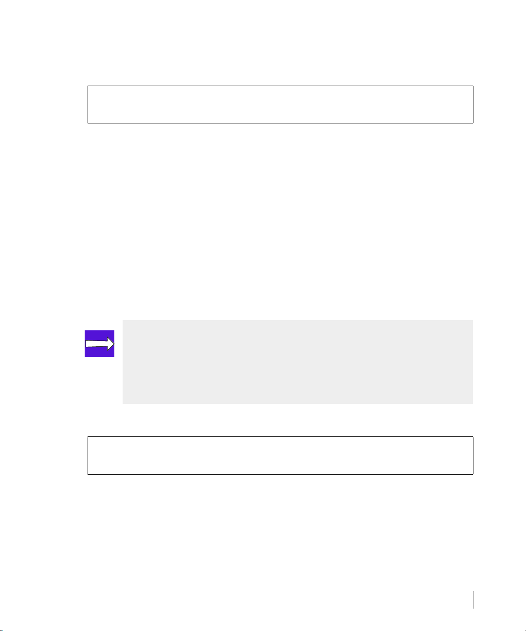
InForm OS Version 2.3.1 Remote Copy User’s Guide
3 On the primary storage server, add pre-existing virtual volumes to the newly created
volume group, Group1, as follows:
On InServ1:
# admitrcopyvv <VV_name> <group_name> <target_name:sec_VV_name>
<VV_name> is the name of the virtual volume (vv1) to be added to the primary volume
group (Group1) specified by the
<group_name> variable. You also need to specify the
<target_name> (for example, InServ2) and the name of the corresponding volume on
the target system (for this example, vv1_remote).
The
admitrcopyvv command adds the specified volume (vv1) to the primary volume
group (Group1). At the same time, it adds the specified volume on the target system
(vv1_remote
page 3.21 (Group1.r112).
) to the corresponding secondary volume group created in step 1 on
3.5.1.4 Start Copying
The final step in setting up unidirectional Remote Copy for a single Remote Copy pair is to start
replication for the volume groups.
NOTE: To perform the initial synchronization using tape backup, use the –-
nosync
that the volumes are already synchronized. This command can also be used for
newly created volumes that have not yet been exported to the hosts. See Initial
Synchronization Using Tape Backup on page 3.38 for complete instructions.
1 On the primary storage server, start replication for a volume group as follows:
On InServ1:
#
startrcopygroup <group_name>
where
<group_name> is the name of the primary volume group (Group 1).
The
startrcopygroup command is mirrored from InServ1 to InServ2 and begins the
copying of data. Because this is the first time this command has been run for this volume
group, the existing data is copied from the primary to the secondary volume group.
option of the startrcopygroup command. This command assumes
Setting Up Remote Copy
3.23
Page 86

Remote Copy User’s Guide InForm OS Version 2.3.1
2 Issue the showrcopy command again to verify that the groups are synchronizing. The
groups are completely synchronized after the SyncStatus is Synced.
On InServ1:
# showrcopy
...
Group Information
Name Target Status Role Mode Options
sync_group_1 InServ2 Started Primary Sync
LocalVV ID RemoteVV ID SyncStatus LastSyncTime
localvv.0 391 remotevv.0 351 Synced NA
localvv.1 392 remotevv.1 352 Synced NA
3.24
Setting Up Remote Copy
Page 87

InForm OS Version 2.3.1 Remote Copy User’s Guide
3.5.1.5 Setting Up Additional Remote Copy Pairs
For configurations that use multiple Remote Copy pairs (also known as N-to-1 or 1-to-N type
configurations), after following the instructions in Setting Up Unidirectional Remote Copy on
page 3.17, repeat the entire process for each additional pair, up to a maximum of two
(for 1-to-N configurations) or four (for N-to-1 configurations) Remote Copy pairs.
Note that for N-to-1 configurations all pairs must share the same secondary storage server, and
for 1-to-N configurations all pairs must share the same primary storage server. See N-to-1
Restrictions on page 2.43 and 1-to-N Restrictions on page 2.44 for additional information and
restrictions regarding configurations with multiple Remote Copy pairs.
NOTE: The transport layer only needs to be set once per system. However, you
should verify the connectivity for each pair in the configuration.
3.5.2 Setting Up Bidirectional Remote Copy
In this section, as illustrated by Figure 3-7 on page 3.26:
■ The members of the Remote Copy pair are an eight-node cluster called InServ1 and a four-
node cluster called InServ2.
■ A virtual volume on InServ1 called vv1 is the only member of Group1.
■ A virtual volume on InServ2 is called vv1_remote and is the only member of
Group1.r112, the secondary group that is automatically created at the same time as
Group1.
Note that vv1 and vv1_remote must be the same size.
■ A virtual volume on InServ2 called vv2 is the only member of Group2.
■ A virtual volume on InServ1 is called vv2_remote and is the only member of
Group2.r125, the secondary group that is automatically created at the same time as
Group2.
Note that vv2 and vv2_remote must be the same size.
Setting Up Remote Copy
3.25
Page 88

Remote Copy User’s Guide InForm OS Version 2.3.1
Node 6 Node 7
Network
InServ1
Node 2 Node 3
InServ2
Group1
vv1
Group1.r112
vv1_remote
172.16.1.12
172.16.2.12
172.16.1.11
172.16.2.11
Target: InSe rv2
Primary Group:
Group2
vv2
Target: InSe rv1
Primary Group:
Secondary Group:
Group2.r125
vv2_remote
Secondary Group:
172.16.1.11
172.16.2.11
172.16.1.12 172.16.2.12
3.26
Figure 3-7. Configuring Bidirectional Remote Copy Connections
NOTE: The following steps are very similar to setting up a unidirectional Remote
Copy, only in this configuration, InServ2 will be the primary server.
To set up volume groups for bidirectional configuration:
1 Issue the following command to create a primary volume group on InServ2:
On InServ2:
#
creatercopygroup <group_name> <target_na me>:<mode>
NOTE: For N-to-1 configurations, only asynchronous periodic mode volume
groups are supported.
Setting Up Remote Copy
Page 89
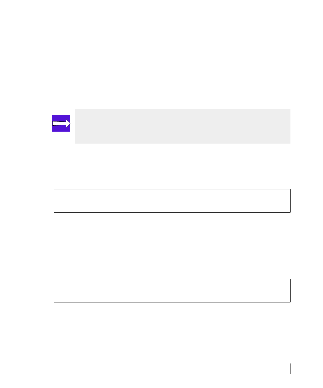
InForm OS Version 2.3.1 Remote Copy User’s Guide
In order to use this command, you must specify a <group_name> (for example, Group2),
the
<target_name> (for example, InServ1) and a mode (sync for synchronous or
periodic for asynchronous periodic).
The creatercopygroup command creates a primary volume group on the primary
storage server, the storage server on which the command is issued (in this case, InServ2).
At the same time, it also creates a corresponding secondary group (Group2.r125) on the
target system (InServ1). The corresponding secondary group uses the naming convention
<primary_group_name>.r<sys_ID>.
NOTE: You can create groups and add volumes to groups without disrupting host
access to volumes. In addition, stopping a Remote Copy volume group does not
prevent a host from accessing the volumes in that group.
2 (Optional). If you chose
synchronization by specifying a resynchronization period as follows. Do not set a
resynchronization period if you plan to perform the initial synchronization using tape
backup, as described beginning on page 3.38.
On InServ2:
# setrcopygroup period <value> <target_name> <group_name>
where
<value> is the resynchronization period, followed by s to denote seconds, m to
denote minutes,
name (InServ1), and <group_name> is the name of the primary volume group on
InServ2 (Group2).
3 On InServ2, add pre-existing virtual volumes to the newly created primary volume group
(Group2) as follows:
On InServ2:
# admitrcopyvv VV_name group_name target_name:sec_VV_name
where
<VV_name> is the name of the virtual volume (vv2) to be added to the primary
volume group (Group2). You also need to specify the target name
that volume group (InServ1)and the name of the secondary volume (vv2.remote).
periodic mode in step 1, you might want to set up automatic
h to denote hours, or d to denote days, <target_name> is the target
<target_name> for
Setting Up Remote Copy
3.27
Page 90

Remote Copy User’s Guide InForm OS Version 2.3.1
The admitrcopyvv command adds the specified volume (vv2) to the primary volume
group (Group2). At the same time, it also adds the secondary volume (vv2.remote) to
the corresponding secondary volume group on the target system (Group2.r125).
4 Start replication for the volume groups created in step 1:
On InServ2:
# startrcopygroup <group_name>
where
<group_name> is the name of the primary volume group (Group2).
The
startrcopygroup command begins the copying of data. Because this is the first time
this command has been run for this volume group, the existing data is copied from the
primary to the secondary volume group.
3.6 Synchronous Long Distance Remote Copy Setup
Use the procedures described in this section to set up Synchronous Long Distance Remote Copy
on your storage servers. See Synchronous Long Distance Configuration on page 2.12 and
Requirements and Restrictions on page 2.41 for information about Synchronous Long Distance
Remote Copy setups.
3.28
In this section, as illustrated by Figure 3-8:
■ The primary system is a four-node cluster called InServA and the backup systems are four-
node clusters called InServB and InServC.
■ InServA is the primary storage system
◆ Target name: InServB
◆ Links:
◆ Node 2 IP address 10.100.33.195
◆ Node 3 IP address 10.101.33.195
◆ Target name: InServC
◆ Links:
◆ Node 2 IP address: 10.100.33.63
◆ Node 3 IP address: 10.101.33.63
Synchronous Long Distance Remote Copy Setup
Page 91

InForm OS Version 2.3.1 Remote Copy User’s Guide
■ InServB is the backup storage system
◆ Target name: InServA
◆ Links:
◆ Node 2 IP address 10.100.33.96
◆ Node 3 IP address 10.101.33.96
◆ Target name: InServC
◆ Links:
◆ Node 0 IP address 10.100.33.63
◆ Node 1 IP address 10.101.33.63
■ InServC is the backup storage system
◆ Target name: InServA
◆ Links:
◆ Node 2 IP address 10.100.33.96
◆ Node 3 IP address 10.101.33.96
◆ Target name: InServB
◆ Links:
◆ Node 2 IP address 10.100.33.195
◆ Node 3 IP address 10.101.33.195
■ Synchronous Remote Copy is used between InServA and InServB. The following WWNs
are used:
◆ InServA:
◆ Node WWN: 2FF70002AC000060
◆ Node 0 WWN: 20110002AC000060
◆ Node 1 WWN: 21320002AC000060
◆ InServB:
◆ Node WWN: 2FF70002AC0000C3
Synchronous Long Distance Remote Copy Setup
3.29
Page 92

Remote Copy User’s Guide InForm OS Version 2.3.1
IP Network
InServA
testgroup
testvv.A.0
Targets: InServB
Primary Group:
testgroup.r96
Secondary Group:
Node 0
Node 1
InServC
Target: InServA
10.100.33.63
10.101.33.63
InServC
Node 2
Node 3
InServB
Target: InServA
10.100.33.195
10.101.33.195
Synchronous Remote Copy between
InServA and InServB
Asynchronous periodic Remote Copy
*
*
testvv.B.0
testvv.A.1
testvv.A.2
testvv.B.1
testvv.B.2
testvv.C.0
testvv.C.1
testvv.C.2
between InServA and InServC
FC Network
InServB
InServC
Node 0
Node 1
Node 2
Node 3
10.100.33.96
10.101.33.96
Node 0
Node 1
Node 2
Node 3
◆ Node 0 WWN: 20210002AC0000C3
◆ Node 1 WWN: 21210002AC0000C3
■ Asynchronous Periodic Remote Copy is used between InServA and InServC.
3.30
Synchronous Long Distance Remote Copy Setup
Figure 3-8. Configuring Synchronous Long Distance Remote Copy Connections
Page 93
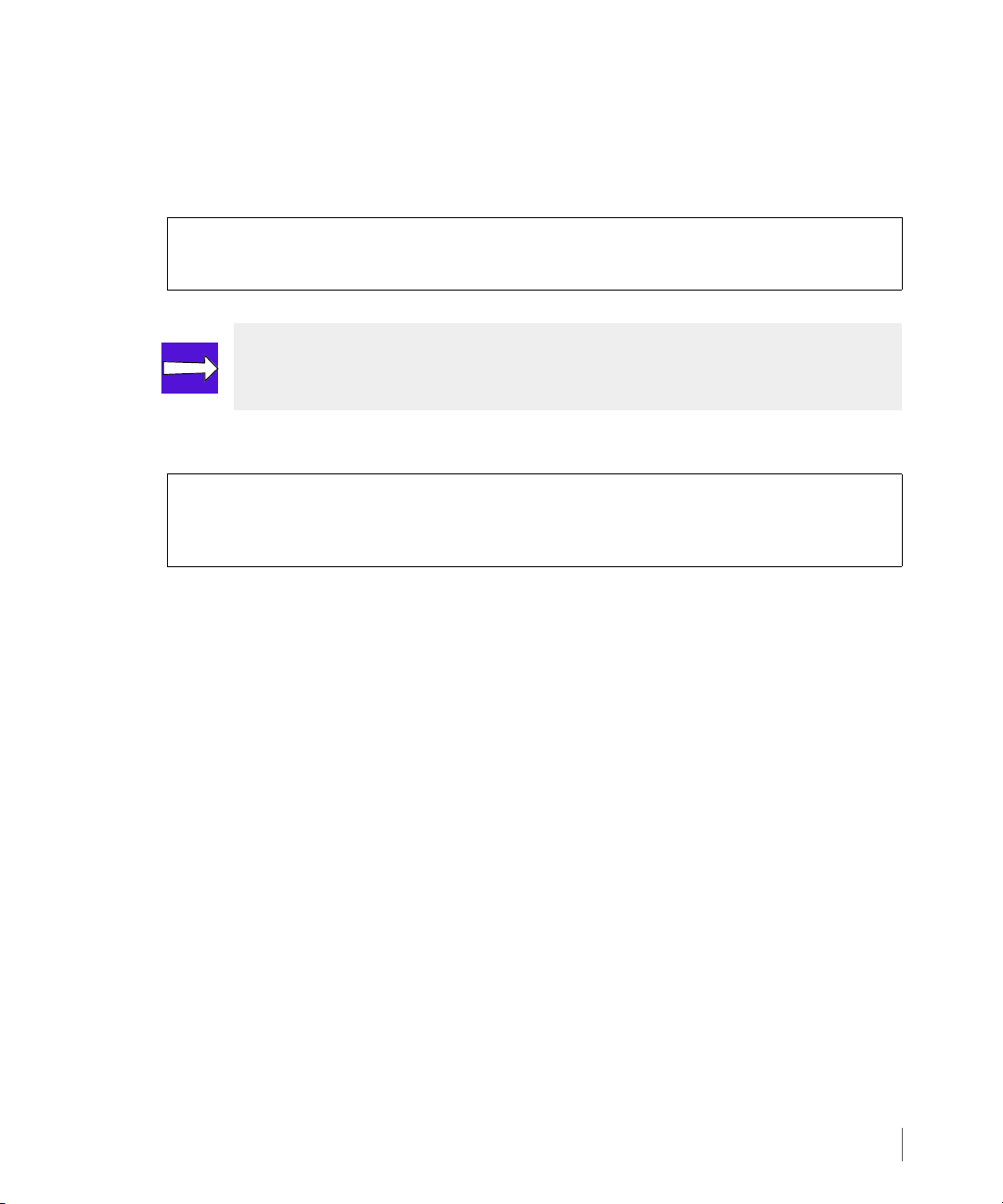
InForm OS Version 2.3.1 Remote Copy User’s Guide
3.6.1 Setting Up the Primary Server
To set up the primary storage server (InServA):
1 Start Remote Copy as follows:
On InServA:
# startrcopy
NOTE: In the following step, the creatercopytarget command must be issued
twice, once for InServB and once for InServC.
2 Define the targets on InServA:
On InServA:
# creatercopytarget <target_name> FC <node_WWN> <N:S:P>:<WWN> <N:S:P>:<WWN>
# creatercopytarget <target_name> IP <N:S:P>:<IP_addr> <N:S:P>:<IP_addr>
◆ <target_name> is the name of the Remote Copy target (for example, InServB and
InServC).
◆ FC states a Fibre Channel link.
◆ IP states an IP link.
For FC setup:
◆ <node_WWN> specifies the WWN of the target node (for example, 2FF70002AC0000C3
for InServB).
◆ <N:S:P>:<WWN> specifies the node, slot, and port of the Fibre Channel adapter port
on the primary system InServA and the WWN of the peer port on the target system
InServB (for example, 0:1:1:20210002AC0000C3 and 1:3:2:21210002AC0000C3).
For IP setup:
◆ <N:S:P>:<IP_addr> specifies the node on InServA that contains the IP connections
to the target (for example, 2:4:1and 3:4:1) and the IP address (
<IP_addr>) for the
target system (for example,10.100.33.63 and 10.101.33.63 for InServC).
Synchronous Long Distance Remote Copy Setup
3.31
Page 94

Remote Copy User’s Guide InForm OS Version 2.3.1
3.6.2 Setting Up the Backup Servers
The commands used to set up the backup storage servers (InServB and InServC) are nearly
the same as those used to set up the primary server (InServA), except that they create the
links in the opposite direction and create a second target for failover purposes.
To set up the backup storage servers (InServB and InServC):
1 Start Remote Copy on InServB as follows:
On InServB:
# startrcopy
2 Define a target for InServB:
On InServB:
#
creatercopytarget <target_name> FC <node _WWN> <N:S:P>:<WWN> <N:S:P>:<WWN>
# creatercopytarget <target_name> IP <N:S:P>:<IP_addr> <N:S:P>:<IP_addr>
◆ <target_name> is the name of the Remote Copy target (for example, InServA and
InServC).
3.32
◆ FC states a Fibre Channel link.
◆ IP states an IP link.
For FC setup:
◆ <node_WWN> specifies the WWN of the target node (for example, 2FF70002AC0000C3
for InServA).
◆ <N:S:P>:<WWN> specifies the node, slot, and port of the Fibre Channel adapter port
on the primary system InServA and the WWN of the peer port on the target system
InServA (for example, 0:1:1:20110002AC000060 and 1:3:2:21320002AC000060).
For IP setup:
◆ <N:S:P>:<IP_addr> specifies the node, slot, and port on InServB that contains the
IP connections to the target (for example, 2:4:1 and 3:4:1) and the IP address
(
<IP_addr>) for the target system (for example,10.100.33.63 and 10.101.33.63 for
InServC).
Synchronous Long Distance Remote Copy Setup
Page 95
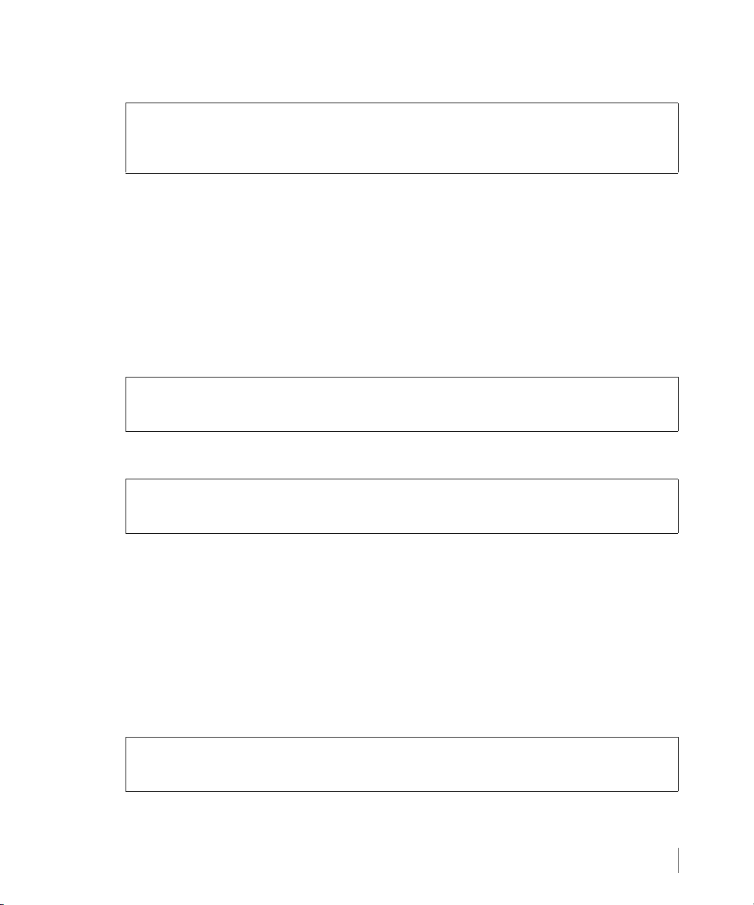
InForm OS Version 2.3.1 Remote Copy User’s Guide
3 Define a second target for InServB:
On InServB:
#
creatercopytarget <target_name> IP <N:S: P>:<link_IP_addr>
<N:S:P>:<link_IP_addr>
◆ <target_name> is the name of the Remote Copy target (for example, InServC).
◆ IP states that this is an IP link.
◆ <node> specifies the node that contains the IP connections to the target (for example
2:4:1and 3:4:1).
◆ <link_IP_addr> is the link IP address for the target system (for example,
10.100.33.96 and 10.101.33.96).
4 Start Remote Copy on InServC as follows:
On InServC:
# startrcopy
5 Define a target for InServC:
On InServC:
#
creatercopytarget <target_name> IP <N:S: P>:<IP_addr> <N:S:P>:<IP_addr>
◆ <target_name> is the name of the Remote Copy target (for example, InServA).
◆ IP states that this is an IP link.
◆ <N:S:P> specifies the node that contains the IP connections to the target (for example
0:2:1 and 1:2:1).
◆ <IP_addr> is the link IP address for the target system (for example, 10.100.33.96
and 10.101.33.96).
6 Define a second target for InServC:
On InServC:
# creatercopytarget <target_name> IP <N:S:P>:<IP_addr> <N:S:P>:<IP_addr>
◆ <target_name> is the name of the Remote Copy target (for example, InServB).
Synchronous Long Distance Remote Copy Setup
3.33
Page 96

Remote Copy User’s Guide InForm OS Version 2.3.1
◆ IP states that this is an IP link.
◆ <node> specifies the node that contains the IP connections to the target (for example
0:1:1 and 1:3:2).
◆ <IP_addr> is the link IP address for the target system (for example, 10.100.33.195
and 10.101.33.195).
3.6.3 Verifying Synchronous Long Distance Remote Copy Setup
X To verify the Synchronous Long Distance Remote Copy setup on the primary and backup
servers, issue the
◆ On InServA:.
# showrcopy
Remote Copy System Information
Status: Started, Normal
Target Information
Name ID Type Status Options Policy
InServB 6 FC ready 2FF70002AC0000C3 mirror_config
InServC 7 IP ready mirror_config
showrcopy command on InServA, InServB, and InServC.
3.34
Link Information
Target Node Address Status Options
InServB 0:1:1 20210002AC0000C3 Up
InServB 1:3:2 21210002AC0000C3 Up
InServC 2:4:1 10.100.33.63 Up
InServC 3:4:1 10.101.33.63 Up
receive 0:1:1 20210002AC0000C3 Up
receive 1:3:2 21210002AC0000C3 Up
receive 2:4:1 receive Up
receive 3:4:1 receive Up
Synchronous Long Distance Remote Copy Setup
Page 97

InForm OS Version 2.3.1 Remote Copy User’s Guide
◆ On InServB:
# showrcopy
Remote Copy System Information
Status: Started, Normal
Target Information
Name ID Type Status Options Policy
InServA 4 FC ready 2FF70002AC000060 mirror_config
InServC 5 IP ready mirror_config
Link Information
Target Node Address Status Options
InServA 0:2:1 20110002AC000060 Up
InServA 1:2:1 21320002AC000060 Up
InServC 2:4:1 10.100.33.63 Up
InServC 3:4:1 10.101.33.63 Up
receive 0:2:1 20110002AC000060 Up
receive 1:2:1 21320002AC000060 Up
receive 2:4:1 receive Up
receive 3:4:1 receive Up
◆ On InServC:
# showrcopy
Remote Copy System Information
Status: Started, Normal
Target Information
Name ID Type Status Options Policy
InServA 3 IP ready mirror_config
InServB 4 IP ready mirror_config
Link Information
Target Node Address Status Options
InServA 0:2:1 10.100.33.96 Up
InServA 1:2:1 10.101.33.96 Up
InServB 0:1:1 10.100.33.195 Up
InServB 1:3:2 10.101.33.195 Up
receive 0:2:1 receive Up
receive 1:2:1 receive Up
Synchronous Long Distance Remote Copy Setup
3.35
Page 98

Remote Copy User’s Guide InForm OS Version 2.3.1
3.6.4 Creating Synchronous Long Distance Remote Copy Volume Groups
NOTE: In the following procedure, it is assumed that the volumes testvv.A.x
have already been created on InServA, volumes
created on InServB, and volumes testvv.C.x have already been created on
InServC.
NOTE: In the following procedure, two target are used, InServB and InServC,
which define the configuration as Synchronous Long Distance Remote Copy.
1 Create and admit the volume group and targets on InServA:
# creatercopygroup testgroup InServB:sync InServC:periodic
# admitrcopyvv testvv.A.0 testgroup InServB:testvv.B.0 InServC:testvv.C.0
# admitrcopyvv testvv.A.1 testgroup InServB:testvv.B.1 InServC:testvv.C.1
# admitrcopyvv testvv.A.2 testgroup InServB:testvv.B.2 InServC:testvv.C.2
testvv.B.x have already been
3.36
In the example above:
◆ testvv.A.0, testvv.A.1, and testvv.A.2 are admitted for the volume group
testgroup.
◆ Servers InServB and InServC are admitted as the targets of server InServA.
◆ Volumes testvv.B.x and testvv.C.x are admitted as secondary volumes for the
primary volumes
2 Start the Remote Copy groups on InServB and InServC.
# startrcopygroup testgroup
The Remote Copy groups are synchronized.
3 Issue the
showrcopy groups command on each server to verify the groups are
synchronized.
Synchronous Long Distance Remote Copy Setup
testvv.A.x.
Page 99

InForm OS Version 2.3.1 Remote Copy User’s Guide
◆ On InServA:
# showrcopy groups
Group Information
Name Target Status Role Mode Options
testgroup InServB Started Primary Sync
LocalVV ID RemoteVV ID SyncStatus LastSyncTime
testvv.A.0 100 testvv.B.0 200 Synced 2008-09-11 17:52:49 PDT
testvv.A.1 101 testvv.B.1 201 Synced 2008-09-11 17:52:49 PDT
testvv.A.2 102 testvv.B.2 202 Synced 2008-09-11 17:52:48 PDT
Name Target Status Role Mode Options
testgroup InServC Started Primary Periodic Last-Sync 2008-09-11
17:52:17 PDT , over_per_alert
LocalVV ID RemoteVV ID SyncStatus LastSyncTime
testvv.A.0 100 testvv.C.0 300 Synced 2008-09-11 17:52:58 PDT
testvv.A.1 101 testvv.C.1 301 Synced 2008-09-11 17:53:01 PDT
testvv.A.2 102 testvv.C.2 302 Synced 2008-09-11 17:53:00 PDT
◆ On InServB:
# showrcopy groups
Group Information
Name Target Status Role Mode Options
testgroup.r96 InServA Started Secondary Sync
LocalVV ID RemoteVV ID SyncStatus LastSyncTime
testvv.B.0 200 testvv.A.0 100 Synced 2008-09-11 17:52:49 PDT
testvv.B.1 201 testvv.A.1 101 Synced 2008-09-11 17:52:49 PDT
testvv.B.2 202 testvv.A.2 102 Synced 2008-09-11 17:52:48 PDT
Name Target Status Role Mode Options
testgroup.r96 InServC Backup Secondary Periodic over_per_alert
LocalVV ID RemoteVV ID SyncStatus LastSyncTime
testvv.B.0 200 testvv.C.0 300 Synced 2008-09-11 17:52:58 PDT
testvv.B.1 201 testvv.C.1 301 Synced 2008-09-11 17:53:01 PDT
testvv.B.2 202 testvv.C.2 302 Synced 2008-09-11 17:53:00 PDT
Synchronous Long Distance Remote Copy Setup
3.37
Page 100

Remote Copy User’s Guide InForm OS Version 2.3.1
◆ On InServC:
# showrcopy groups
Group Information
Name Target Status Role Mode Options
testgroup.r96 InServA Started Secondary Periodic over_per_alert
LocalVV ID RemoteVV ID SyncStatus LastSyncTime
testvv.C.0 300 testvv.A.0 100 Synced 2008-09-11 17:52:58 PDT
testvv.C.1 301 testvv.A.1 101 Synced 2008-09-11 17:53:01 PDT
testvv.C.2 302 testvv.A.2 102 Synced 2008-09-11 17:53:00 PDT
Name Target Status Role Mode Options
testgroup.r96 InServB Backup Secondary Periodic over_per_alert
LocalVV ID RemoteVV ID SyncStatus LastSyncTime
testvv.C.0 300 testvv.B.0 200 Synced 2008-09-11 17:52:49 PDT
testvv.C.1 301 testvv.B.1 201 Synced 2008-09-11 17:52:50 PDT
testvv.C.2 302 testvv.B.2 202 Synced 2008-09-11 17:52:48 PDT
As shown in the examples above, once the synchronization completes, the primary and
secondary volumes’
SyncStatus should show a status of Synced.
3.38
3.7 Initial Synchronization Using Tape Backup
For a very large volume, it might be faster to perform the initial synchronization of the backup
server with the primary server by backing up the primary volume group to tape and then
restoring the secondary volume group from tape rather than synchronizing the volume groups
over the Remote Copy links.
To perform the initial synchronization using tape backup, follow the procedures described in
this chapter for setting up Remote Copy. However, when issuing
<group_name>
use the -nosync option. This option indicates that the volumes do not need to be
synchronized, and marks them as
3.7.1 Synchronizing Volume Groups
If the primary volume group needs to be used for writes before the secondary volume group is
initialized from the tape backup, use the following procedure to bring the primary and
secondary volume groups into synchronization and to start Remote Copy operations for the
storage server pair.
Initial Synchronization Using Tape Backup
on the primary server (as described in Start Copying on page 3.23), be sure to
Synced.
startrcopygroup
 Loading...