

Page 1

HP Remote Assistant
User's Guide
HP Part No. 5964-3175
Printed in USA • July 1996
Page 2

Notice
Notice
The information contained in this document is subject to change without notice.
Hewlett-Packard makes no warranty of any kind with regard to this material, including, but not
limited to, the implied warranties of merchantability and fitness for a particular purpose.
Hewlett-Packard shall not be liable for errors contained herein or for incidental or consequential
damages in connection with the furnishing, performance, or use of this material. HewlettPackard assumes no responsibility for the use or reliability of its software on equipment that is
not furnished by Hewlett-Packard.
This document contains proprietary information that is protected by copyright. All rights are
reserved. No part of this document may be photocopied, reproduced, or translated to another
language without the prior written consent of Hewlett-Packard Company.
Materials reprinted with the permission of FutureSoft. FutureSoft makes no warranty of any
kind regarding the accuracy, correctness, or sufficiency of the information in the publication,
and the use of any information therein is or will be free from claims of intellectual property
infringement of any kind. Materials reprinted with the permission of Symantec. Symantec
makes no warranty of any kind regarding the accuracy, correctness, or sufficiency of the
information in the publication, and the use of any information therein is or will be free from
claims of intellectual property infringement of any kind.
Remote Assistant's TAP paging software utilizes portions of AIRSOURCE from Silverlake
Communications Incorporated. Likewise, materials used in the manual are reprinted with the
permission of Silverlake Communications Incorporated. Remote Assistant utilizes µC/OS, The
Real Time Kernel, a software program written by Jean J. Labrosse of Plantation, Florida.
Terminal Plus is a U.S. registered trademark of FutureSoft Corporation. Microsoft and MSDOS are U.S. registered trademarks of Microsoft Corp. Windows and Windows NT are
trademarks of Microsoft Corp. Novell and NetWare are registered trademarks of Novell, Inc.
CompuServe is a U.S. registered trademark of CompuServe, Inc. IBM and OS/2 are registered
trademarks of the International Business Machines Corp. SCO, SCO UNIX, and Open
Desktop are registered trademarks of The Santa Cruz Operation. SCO Open Server and SCO
MPX are trademarks of The Santa Cruz Operation. UNIX is a registered trademark in the
United States and other countries, licensed exclusively through X/Open Company Limited.
Banyan and VINES are registered trademarks of Banyan Systems, Inc. Hayes is a trademark of
Hayes Microcomputer Products Incorporated. CompuServe is a U.S. registered trademark of
CompuServe, Inc.
Network Server Division
5301 Stevens Creek Boulevard
P.O. Box 58059
Santa Clara, CA 95052-8059, USA
©Copyright 1996, Hewlett-Packard Company
ii
Page 3

License Agreement
License Agreement
Software License Agreement
Please carefully read this license agreement before proceeding to open the media
envelope. Rights in the software are offered only on the condition that the customer
agrees to all terms and conditions of the license agreement. Proceeding to open the
media envelope or install the software indicates your acceptance of these terms and
conditions. If you do not agree to the license agreement, you may return the software
for a refund.
In return for payment of the applicable fee, Hewlett-Packard grants the Customer a
license in the software, subject to the following:
1. Use. The software is comprised of (a) server utilities and agents which may be
installed on the server in which the HP Remote Assistant EISA Board is installed;
(b) communications software which may be installed on one or more remote
personal computer consoles. Under no circumstances may the console software
copies be used concurrently (i.e. by more than a single user).
2. Copies and Adaptations. Customer may make copies or adaptations of the software
(a) for archival purposes or (b) when copying or adaptation is an essential step in
the use of the software with a computer so long as the copies and adaptations are
used in no other manner.
3. Ownership. Customer agrees that it does not have any title or ownership of the
software, other than ownership of the physical media. Customer acknowledges and
agrees that the software is copyrighted and protected under the copyright laws.
Customer acknowledges and agrees that the software may have been developed by
a third party software supplier named in the copyright notices included with the
software, who shall be authorized to hold the Customer responsible for any
copyright infringement or violation of this Agreement. Customer may not reverse
assemble or decompile the software unless authorized by law.
4. Transfer of Rights in Software. Customer may transfer rights in the software to a
third party only as part of the transfer of all rights and only if Customer obtains the
prior agreement of the third party to be bound by the terms of this License
Agreement. Upon such a transfer, Customer agrees that its rights in the software
are terminated and that it will either destroy its copies and adaptations or deliver
them to the third party.
iii
Page 4

License Agreement
5. Sub licensing and Distribution. Customer may not lease, sub license the software
or distribute copies or adaptations of the software to the public in physical media or
by telecommunication without the prior written consent of Hewlett-Packard.
6. Termination. Hewlett-Packard may terminate this software license for failure to
comply with any of these terms provided Hewlett-Packard has requested Customer
to cure the failure and Customer has failed to do so within thirty (30) days of such
notice.
7. Updates and Upgrades. Customer agrees that the software does not include
updates and upgrades which may be available from Hewlett-Packard under a
separate support agreement.
8. Export Clause. Customer agrees not to export or re-export the software or any
copy or adaptation in violation of the U.S. Export Administration regulations or
other applicable regulation.
9. U.S. Government Restricted Rights. Use, duplication, or disclosure by the U.S.
Government is subject to restrictions as set forth in subparagraph (c)(1)(ii) of the
Rights in Technical Data and Computer Software clause in DFARS 252.227-7013.
Hewlett-Packard Company. 3000 Hanover Street, Palo Alto, CA 94304 U.S.A.
Rights for non-DOD U.S. Government Departments and Agencies are as set forth
in FAR 52.227-19(c)(1,2).
iv
Page 5

Regulatory Information
Regulatory Information
Notice for USA: FCC Statements
This device complies with part 15 of the FCC Rules. Operation is subject to the
following two conditions: (1) This device may not cause harmful interference, and (2)
this device must accept any interference received, including interference that may
cause undesired operation.
Class B Product Statement
This equipment has been tested and found to comply with the limits for a Class B
digital device, pursuant to Part 15 of the FCC Rules. These limits are designed to
provide reasonable protection against harmful interference in a residential installation.
This equipment generates and uses, and can radiate radio frequency energy and, if not
installed and used in accordance with instructions, may cause harmful interference to
radio communications. However, there is no guarantee that interference will not occur
in a particular installation. If this equipment does cause harmful interference to radio
or television reception, which can be determined by turning the equipment off and on,
the user is encouraged to correct the interference by one or more of the following
measures:
• Reorient or relocate the receiving antenna.
• Increase the separation between the equipment and the receiver.
• Connect the equipment into an outlet on a circuit deferent from that to which the
receiver is connected.
• Consult the dealer or an experienced radio/television technician for help.
Hewlett-Packard’s system certification tests were conducted with HP-supported
peripheral devices and HP shielded cables, such as those you receive with your
computer. Changes or modifications not expressly approved by Hewlett-Packard could
void the user’s authority to operate the equipment. Cables used with this device must
be properly shielded to comply with the requirements of the FCC.
v
Page 6

Regulatory Information
FCC Regulations for Telephone Line Interconnection
• This equipment complies with Part 68 of the FCC rules. On the outside surface of
this equipment is a label that contains among other information, the FCC
registration, the FCC registration number and ringer equivalence number (REN).
If requested, this information must be provided to the telephone company.
• This equipment uses the following Universal Service Code (USOC) jacks: RJ11C
or RJ11W (single line).
• The REN equivalence number (REN) is used to determine the quantity of devices
which may be connected to the telephone line. Excessive REN’s on the telephone
line may result in the devices not ringing in response to an incoming call. In most,
but not all areas, the sum of the REN’s should not exceed five (5.0). To be certain
of the number of devices that may be connected to the line, as determined by the
total REN’s, contact the telephone company to determine the maximum REN for
the calling area.
• If this equipment causes harm to the telephone network, the telephone company
will, where practicable, notify you in advance that temporary discontinuance of
service may be required. If advance notice isn’t practical, the telephone company
will notify the customer as soon as possible. Also, you will be advised of your right
to file a complaint with the FCC if you believe it is necessary.
• The telephone company may make changes in its facilities, equipment, operations,
or procedures that could affect the operation of the equipment. If this happens, the
telephone company will provide advance notice in order for you to make the
necessary modifications in order to maintain uninterrupted service.
• If trouble is experienced with this equipment, please contact Hewlett-Packard, HP
Santa Clara Site Customer Information Center, 5301 Stevens Creek Blvd., Santa
Clara, California, 95052-8059, USA (Telephone: 1-800-752-0900) for repair
and/or warranty information. If the trouble is causing harm to the telephone
network, the telephone company may request you remove the equipment from the
network until the problem is resolved.
• No repairs are to made by you. Repairs are to be made only by Hewlett-Packard or
its licensees. Unauthorized repairs void registration and warranty.
vi
Page 7

Regulatory Information
• This equipment cannot be used on telephone company-provided coin service.
Connection to Party Line Service is subject to state tariffs. (Contact the state public
utility commission, public service commission or corporation commission for
information.)
• If so required, this equipment is hearing-aid compatible.
Notice for Canada: DOC Requirements
This digital apparatus does not exceed the Class B limits for radio noise emissions
from digital apparatus as set out in the interference-causing equipment standard
entitled “Digital Apparatus,” ICES-003 of the Department of Communications.
Cet appareil numérique respect les limites de bruits radioélectriques applicables aux
appareils numériques de Class B prescrites dans la norme sur le matériel brouilleur:
“Appareils Numériques,” NMB-003 édictée par le ministre des Communications.
DOC Terminal Equipment Warnings
NOTICE: The Canadian Department of Communications label identifies certified
equipment. This certification means that the equipment meets certain
telecommunication network protective operational and safety requirements. The
Department does not guarantee the equipment will operate to the user’s satisfaction.
Before installing this equipment, users should ensure that it is permissible to be
connected to the facilities of the local telecommunications company. The equipment
must also be installed using an acceptable method of connection. In some cases, the
company’s inside wiring associated with a single line individual service may be
extended by means of a certified connector assembly (telephone extension cord). The
customer should be aware that compliance with the above conditions may not prevent
degradation of service in some situations.
Repairs to certified equipment should be made by an authorized Canadian
maintenance facility designated by supplier. Any repairs or alterations made by the
user to this equipment, or equipment malfunctions, may give the telecommunications
company cause to request the user to disconnect the equipment.
Users should ensure for their own protection that the electrical ground connections of
the power utility, telephone lines and internal metallic water pipe system, if present,
are connected together. This precaution may be particularly important in rural areas.
vii
Page 8

Regulatory Information
The Load Number (LN) assigned to each terminal device denotes the percentage of the
total load to be connected to a telephone loop which is used by the device to prevent
overloading. The termination on a loop may consist of any combination of devices
subject only to the requirement that the total of the Load Numbers of all the devices
does not exceed 100. The Load number for this product is 33.
CAUTION Users should not attempt to make such connections themselves, but
should contact the appropriate electric inspection authority, or
electrician, as appropriate.
Notice for Sweden: National Post and Telecom Agency
Statement
The LAM Interface shall be connected to SELV (max. 42.4 V peak, or 60 V dc)
according to EN 60950. (The internal modem complies with this requirement.)
Notice for UK: General Approval
Pursuant to Section 22 of Telecommunications Act of 1984, this product is approved
for indirect connection to Public Telecommunications systems within the United
Kingdom under the General Approval number NS/G/1234/J/100003.
Safety
To reduce the possibility of an electric shock from the telephone network, plug the
computer into the AC outlet prior to connecting the network. Also, disconnect the
network before unplugging the computer from the AC power outlet.
Battery Disposal
The HP Remote Assistant EISA Board includes a rechargeable nickel-cadmium battery
(HP Part No. D2967-63214). This battery must be recycled or disposed of properly.
Contact your Hewlett-Packard representative for information on battery recycling. (In
the USA and Canada, call 1-800-333-1917.) For more information on battery
operations, see Appendix G.
CAUTION Do NOT crush, puncture, or incinerate the battery. Do NOT short the
battery’s external contacts.
viii
Page 9

Regulatory Information
Declaration of Conformity
DECLARATION OF CONFORMITY
according to ISO/IEC Guide 22 and EN 45014
Manufacturer’s Name: Hewlett-Packard Company Hewlett-Packard Pte Ltd
Manufacturer’s Address: 5301 Stevens Creek Blvd. 452 Alexandra Road
declares, that the product
Product Name: Remote Assistant
Model Number(s): D2967C, D2968C, D2969C
Product Options: All
conforms to the following Product Specifications:
Safety: IEC 950:1991 + A1, A2 / EN 60950:1992 + A1, A2
EMC: CISPR 22:1993 / EN 55022: 1994 - Class B
EN 50082-1:1992 - Generic Immunity
Supplementary Information:
The product herewith complies with the requirements of the Low Voltage Directive 73/23/EEC and the EMC
Directive 89/336/EEC.
1) The Product was tested in a typical configuration with Hewlett-Packard peripherals.
2) Models configured with a network interface card comply with CISPR 22 / EN 55022 Class A limits.
Santa Clara, CA 95052 Singapore 119951
USA
1, 2
IEC 801-2:1991, 4 kV CD, 8 kV AD
IEC 801-3:1984, 3V/m
IEC 801-4:1988, 0.5 kV Signal Lines, 1 kV Power Lines
Santa Clara, June 14, 1996
Nigel Marrion / Quality Manager
Singapore, June 14, 1996
Seah Beng Geok / Quality Manager
European Contact: Your local Hewlett-Packard Sales and Service Office or Hewlett-Packard GmbH,
Department ZQ / Standards Europe, Herrenberger Straße 130, D-7030 Böblingen (FAX: + 49-7031-143143)
ix
Page 10

Limited Warranty
Limited Warranty
Software Warranty
Software and Media: HP warrants for a period of ninety (90) days from the date of the
purchase (a) the media is free from defects in materials and workmanship, and (b) that
the software product will execute its programming instructions when properly
installed. HP does not warrant that the operation of the software will be uninterrupted
or error free. In the event that the media is defective during the warranty period or the
software fails to execute its programming instructions during the warranty period,
Customer’s remedy shall be a refund or replacement. Should HP be unable to replace
the media or software within a reasonable amount of time, Customer’s alternate
remedy shall be a refund of the purchase price upon return of the product and all
copies.
Documentation:
Notice of Warranty Claims: Customer must notify HP in writing of any warranty
claim not later than thirty (30) days after the expiration of the warranty period.
Limitation of Warranty: HP makes no other express or implied warranty and HP
specifically disclaims any implied warranty of merchantability or fitness for a
particular purpose.
Exclusive Remedies: The remedies provided above are customer’s sole and exclusive
remedies. In no event shall HP be liable for any direct, indirect, special, incidental or
consequential damages (including lost profit) whether based on warranty, contract, tort
or any other legal theory.
All documentation is provided "as-is" without warranty.
Hardware Warranty
• This HP accessory is covered by a limited hardware warranty for a period of one
year from receipt by the original end-user purchaser.
• If this accessory is installed in an HP computer that is covered by an on-site
warranty, the accessory will be serviced on-site for the remainder of the original
computer warranty period.
• In all other cases, warranty service for this accessory will be on a Return-to-HP
basis.
x
Page 11

Limited Warranty
• Refer to the warranty statement provided with your HP computer for warranty
limitations, customer responsibilities, and other terms and conditions.
• The battery on board the HP Remote Assistant EISA Board is a customer-
replaceable consumable and is not covered under this warranty.
xi
Page 12

Technical Support
Technical Support
Telephone Support
The HP-supplied hardware and software in HP servers are covered by no-charge
telephone assistance during the warranty period. In some geographic areas this
telephone support is provided by Hewlett-Packard; in other areas, telephone support is
provided by your reseller.
For non-HP-supplied products, support numbers are included in the product
documentation or are available from your reseller.
Hewlett-Packard provides telephone assistance in installing, configuring, and
diagnosing the server such that one local client PC is able to log into an HP-supported
network operating system.
Assistance with additional functions, such as system design, operating system
upgrades, or performance optimization—and assistance with other technical areas,
such as cabling, non-HP hardware, or multiple operating system environments—is
available from Hewlett-Packard, resellers, or consultants at additional charge. For
example, HP offers Network Phone-In Support Service with a 7-day, 24-hour option
for network operating systems and multi-vendor hardware. Contact your local HP
office for details.
Obtaining HP Repair and Telephone Support
U.S. and Canada. For hardware service and telephone support, contact either:
• Participating Service Authorized HP Personal Computer Reseller
• HP Customer Support Center (Colorado) (1 970) 635-1000 from 6 AM to
8 PM Mountain Time on Monday through Friday and from 9 AM to 3 PM
Mountain Time on Saturday
Europe. For hardware service and telephone support, contact either:
• Participating Service Authorized HP Personal Computer Reseller
• HP Customer Support Center (Amsterdam):
Dutch language (+31 20) 581-3331
English language (+31 20) 581-3330
German language (+31 20) 581-3333
French language (+31 20) 581-3332
xii
Page 13

Technical Support
Italian language (+31 20) 581-3338
Spanish language (+31 20) 581-3339
Other countries. For hardware service, contact your local HP office. For telephone
support, contact your authorized HP reseller.
Using Other Information Services
Worldwide, access the HP NetServer World Wide Web home page:
http://www.hp.com/go/netserver
For software patches and driver updates:
In the US, access the HP PC Support BBS: (408) 553-3500
Worldwide, access the HP FTP Server:
ftp.netserver.hp.com
LOGON: anonymous
PASSWORD: <your e-mail address>
For more information on the product:
HP Audio Tips & Fax Info (HPFirst): (800) 333-1917 or (208) 344-4809
For information on CompuServe call
(800) 848-8990 U.S.
(614) 457-8650 Canada
After logging in to CompuServe, type GO HPSYS to get onto the HP Forum.
xiii
Page 14

Documentation
Documentation
HP Remote Assistant includes the following documentation:
• This guide, which describes how to install and use HP Remote Assistant to manage
network servers. It also provides installation instructions for HP Remote Assistant
Communications Software (Terminal Plus) and pcANYWHERE32.
• Application on-line help, which is available for the HP Remote Assistant
Communications Software and pcANYWHERE32.
• The HP Remote Assistant README.TXT, file which is available on both the HP
Remote Assistant Console Diskette and the HP Remote Assistant Server Diskette.
Use the README file to obtain the very latest information about HP Remote
Assistant.
xiv
Page 15

Contents
Quick Start ...............................................................................................................1
1 Introducing HP Remote Assistant........................................................................5
Package Contents .................................................................................................7
Who Should Use This Guide..................................................................................8
HP Remote Assistant Features and Functions.......................................................8
HP Remote Assistant System Requirements .......................................................11
2 Hardware Installation and Configuration ..........................................................13
Installing the HP Remote Assistant EISA Board...................................................14
Connecting the Power Control Cable ...............................................................14
Verifying Board Installation..............................................................................21
Using the EISA Configuration Utility.....................................................................22
Setting Up the Remote Connection......................................................................25
Using the On-board Modem (Model D2968C)..................................................26
Using the On-board Modem (Int'l Modem Model D2969C)...............................27
Using an External Modem................................................................................28
Using a Direct Serial Connection.....................................................................29
Configuring the HP Remote Assistant..................................................................31
Starting the HP Remote Assistant Configuration Utility....................................32
The Main Screen.............................................................................................33
Navigating the Configuration Utility..................................................................33
Configuring the HP Remote Assistant Board....................................................34
Configuring Event Management ...................................................................... 35
Setting Sensor Thresholds...............................................................................38
Configuring Communications...........................................................................40
Remote Terminal.............................................................................................44
Identifying the Server ......................................................................................45
Selecting Keyboard Layouts ............................................................................45
Configuring Administrator Names....................................................................46
Performing Diagnostics....................................................................................52
Viewing the Event Log.....................................................................................55
Viewing Current Status....................................................................................56
Shutting Down the Board.................................................................................57
3 Server Software Installation and Configuration................................................59
xv
Page 16

Contents
Server Installation Overview................................................................................60
Using Pager Services..........................................................................................60
Installing the DOS-Based HP Remote Assistant Server Software ........................61
Installing the NOS-Based HP Remote Assistant Server Software ........................63
Installing the Server Software for Novell NetWare...........................................64
Setting Up the SNMP Agent for NetWare ........................................................65
Setting Up ASR for NetWare...........................................................................68
Installing the Server Software for Microsoft Windows NT.................................70
Setting Up the SNMP Agent, ASR, and Console Redirection for Windows NT.71
Installing the Server Software for OS/2............................................................76
Setting Up ASR for OS/2.................................................................................76
Installing the Server Software for SCO UNIX...................................................78
Setting Up ASR for SCO UNIX........................................................................78
Configuring the SNMP Agent to Send Traps to Your Console..............................81
4 Setting Up the Remote Console.........................................................................83
Remote Console Installation Overview................................................................84
Setting Up Terminal Emulation............................................................................84
Option 1: Managing a server from a remote PC console..................................84
Windows NT Graphics Console Redirection.....................................................85
Option 2: Managing a server using a dedicated terminal or other terminal
emulation package ..........................................................................................87
Connecting to HP Remote Assistant from an HP NSA Management Console......90
Running Terminal Plus from HP NetServer Assistant.......................................92
5 Using HP Remote Assistant to Manage Server Operations..............................93
Remotely Logging In to the Server.......................................................................93
Logging In with Dial-Back ................................................................................94
Remote Assistant Server Management Program Options ....................................95
1. Show Event Log ..........................................................................................95
2. Show Status ................................................................................................97
3. Console Redirection.....................................................................................99
4. Server Reset Menu....................................................................................102
5. DOS File Transfer......................................................................................103
6. Run Server Utilities....................................................................................105
7. Bus Utilization History................................................................................107
8. Event Management Configuration..............................................................108
9. Administrator/Pager Configuration.............................................................110
xvi
Page 17

Contents
X. Disconnect ................................................................................................112
Using the SNMP Manager to Query HP Remote Assistant.................................113
Compiling the MIB Under OpenView..............................................................113
Defining a Query ...........................................................................................114
Viewing HP Remote Assistant Alarms With HP NSA .........................................118
6 Troubleshooting...............................................................................................121
Problems With Installation.................................................................................121
External Modem................................................................................................122
Paging...............................................................................................................122
Remote Console................................................................................................124
DOS File Transfer .............................................................................................126
A Event Codes .....................................................................................................127
B Recommended Modems ..................................................................................131
C Modem Commands ..........................................................................................133
AT Commands ..................................................................................................133
S-Register Summary.........................................................................................139
Result Code Summary.......................................................................................140
D Keyboard Mapping...........................................................................................143
E Graceful Shutdown Keystroke Syntax ............................................................145
General Guidelines............................................................................................145
Syntax Rules.....................................................................................................145
Examples ......................................................................................................146
Keystroke Codes ...............................................................................................147
F Technical Specifications..................................................................................149
G Battery Operation.............................................................................................151
Charging............................................................................................................151
Battery Operation ..............................................................................................152
Shutting Down the Board to Conserve Battery Power ........................................152
Life Expectancy.................................................................................................153
Replacement.....................................................................................................153
Disposal.............................................................................................................153
H LED Codes........................................................................................................155
Processor Failure Codes................................................................................155
Memory Failure Codes ..................................................................................156
xvii
Page 18

Contents
Internal Peripheral Failure Codes...................................................................158
External Peripheral Failure Codes.................................................................161
I Keyboard Layouts..............................................................................................167
xviii
Page 19

Quick Start
This chapter provides a quick overview of the steps required to set up and use
HP Remote Assistant. If you have experience setting up computer hardware and
software you can use the following section as a brief installation guide. The
installation of the HP Remote Assistant accessory board requires the prior completion
of system installation and configuration. It assumes that you have a bootable CD-ROM
drive, and 8 MB of unallocated space on your hard disk for a Utility Partition. At any
point, you can refer to the more in-depth description of the process starting with
Chapter 2.
1. Install and set up hardware at the server (see Chapter 2 for detailed
instructions):
• Install the HP Remote Assistant accessory board.
• Connect the power control cable to the HP Remote Assistant board and HP
NetServer system.
• Set up the modem or direct connection:
◊ For Remote Assistant models with built-in modems (D2968C and D2969C):
Connect the modem RJ-11 cable (provided), or the Line Access Module (LAM)
to the HP Remote Assistant modem. Connect the other end of the cable to the
phone jack.
◊ For Remote Assistant models that require an external modem (D2967C):
Connect a serial modem cable (not provided) to the HP Remote Assistant serial
port and connect the other end to the external modem.
◊ For Remote Assistant direct serial connections: Connect a null-modem cable
(not provided) to the HP Remote Assistant board and join the other end to the
terminal.
• Boot the HP NetServer Navigator CD-ROM (provided), and run the server's EISA
Configuration Utility to configure the HP Remote Assistant board. Follow
directions to select a serial interface COM port. Save the configuration and reboot
the server.
• Install or update the Utility Partition using the Configuration Assistant.
1
Page 20

Quick Start
• From the HP NetServer Navigator CD-ROM, run the HP Remote Assistant
Configuration Utility (select HP NetServer Utilities and move HP NetServer
Utilities from the Navigator Main Menu). Set up: connection type (modem or
direct), administrator access (required), event management, sensor and
measurement thresholds, and paging notification.
2. Install server software (see Chapter 3 for detailed instructions):
• Boot the HP NetServer Navigator CD-ROM.
• If you can't install a Utility Partition on your HP NetServer, install the DOS-based
HP Remote Assistant server software on a bootable DOS partition (see Chapter 3).
SCO UNIX does not support a bootable HP NetServer Navigator Utility Partition.
• Install the NOS-based HP Remote Assistant server software (NOS dependent, see
instructions in Chapter 3).
NOTE You will need at least 8MB of unallocated disk space to accommodate the
server software.
• For Windows NT servers, configure pcANYWHERE32 for the HP Remote
Assistant modem (see Chapter 3).
• Configure the SNMP Agent to send traps to your console (NOS dependent, see
instructions in Chapter 3).
3. Install remote console software (see Chapter 4 for detailed instructions):
• Set up terminal emulation.
◊ Option 1: If you are managing a server from a Windows 3.1, Windows for
Workgroups, Windows 3.51 NT, or Windows 95 PC console, install the
Terminal Plus software (run setup.exe from the HP Remote Assistant Console
Diskette).
In addition, if you have a Remote Assistant board in a Windows NT 3.51 server
and want to be able to redirect control of your server to a remote Windows NT
3.51 PC or Windows 95 console, also install the pcANYWHERE32 software
(run setup.exe from the pcANYWHERE32, Diskette 1).
◊ Option 2: If you are managing a server using a direct terminal connection, or
you are using a terminal emulation package other than Terminal Plus, follow
the instructions listed in Chapter 4.
• Connect to an HP Remote Assistant from an HP NetServer Assistant management
console (optional—see the instructions listed in Chapter 4).
2
Page 21

Quick Start
4. Make your first remote connection (see Chapter 5 for detailed instructions):
If you plan on using console redirection for your Windows NT 3.51 server, be sure that
pcANYWHERE32 is already installed and configured as a host for your remote
console. This should have been done when you installed pcANYWHERE32 (see
Chapter 3).
NOTE In the default installation, pcANYWHERE32 runs as a startup service on
your server and is therefore always ready for a call from your remote console.
At the remote console, start your terminal emulation software:
1. From the Windows Program Manager, double-click the HP Remote Assistant icon
from the HP Remote Assistant program group to run Terminal Plus.
After starting Terminal Plus, you should see your modem initialization string
displayed and an "OK" to show that your modem is ready.
NOTE Your modem type and settings should have been configured during the
installation of Terminal Plus (see Chapter 4).
2. From the remote console, click the HP Remote Assistant group from the Windows
Program Manager. Do one of the following:
◊ Click Phone from the toolbar. Then click Dial from the drop-down menu.
Enter your server's phone number, if necessary (including an outside line prefix
number and area code if applicable).
◊ Click Phone from the toolbar. Then click Enter dialer Mode. Set up your
server’s name and phone number, and click the Dial button to connect.
3. Once you are connected, press Enter several times (if you are using a direct
connection, press Ctrl-Break, then Enter) to display the Login Name prompt.
4. At the Login Name prompt, enter a valid administrator name that you configured
using the HP Remote Assistant Configuration Utility.
3
Page 22

Quick Start
5. At the password prompt, enter the password that you specified in the HP Remote
Assistant Configuration Utility. When the server accepts the password (and if no
dial-back number was specified), the HP Remote Assistant Management Program
starts up and displays its Main Menu:
HP Remote Assistant Main Menu
Server Name: HP NetServer Server ID: 001
1. Show Event Log
2. Show Status
3. Console Redirection
4. Server Reset Menu
5. DOS File Transfer
6. Launch DOS Utilities
7. Bus Utilization History
8. Event Management Configuration
9. Administrator/Pager Configuration
X. Disconnect
4
Page 23

1 Introducing HP Remote Assistant
HP Remote Assistant combines an intelligent EISA board and manager software to
provide a powerful solution for remote server management, including monitoring and
notification of server operations and events.
HP Remote Assistant can be used independent of the Network Operating System
(NOS) that is running on the server. Combining Remote Assistant capabilities with the
HP NetServer Assistant server management software tool provides network
administrators with comprehensive server management.
The HP Remote Assistant solution consists of:
• An HP Remote Assistant plug-in circuit board which includes a processor
permitting server access independent of the server's operating status.
• A management application stored in the board firmware that provides unattended
server control and management. (HP Remote Assistant can even power cycle the
server if conditions require it.) An administrator can also use the management
software to transfer files between the server and remote console and run DOS
utilities on the file server. (For example, to remotely update the server’s BIOS.)
• A DOS-based configuration utility for setting up HP Remote Assistant
management parameters. You can use the utility to setup parameters for pager
alerts and to create administrator aliases for operation from different remote
consoles.
• Optimized Windows-based terminal emulation software with which an
administrator can easily connect to the HP Remote Assistant board from a remote
console and run the management application stored on the HP Remote Assistant
board. (An administrator can also use any ANSI terminal emulator or a dedicated
terminal to communicate with the server and run the management application.)
• Automatic Server Restart (ASR) drivers that provide quick recovery from a system
crash or hang.
• SNMP Agents (NetWare and Windows NT only) for in-band (across the network)
gathering of information and for alert generation.
• pcANYWHERE32 for Windows NT graphics redirection.
5
Page 24
1 Introduction
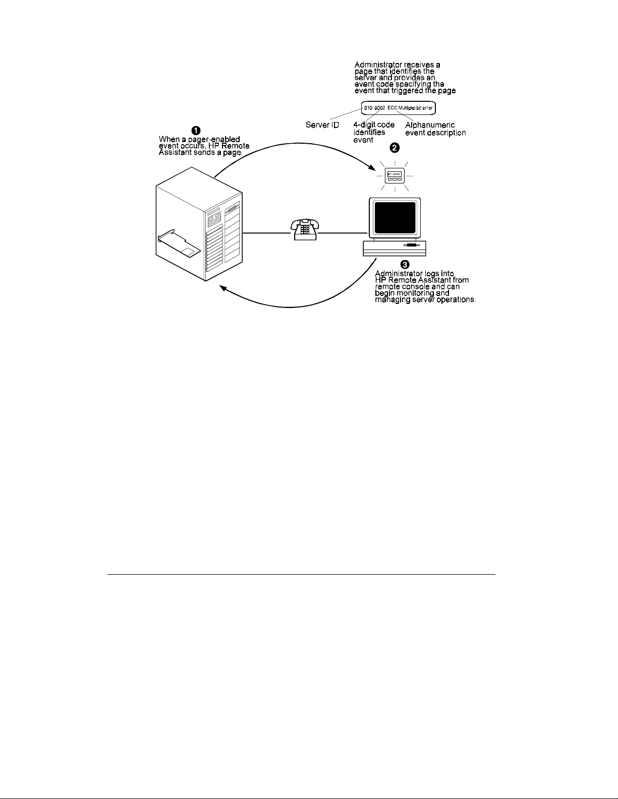
Figure 1-1. HP Remote Assistant Management Process
HP Remote Assistant frees you from round-the-clock server monitoring. If HP Remote
Assistant detects a problem that it cannot correct, it immediately notifies the assigned
administrator by:
• sending a page with a message that identifies the server and the nature of the
problem
• generating an SNMP alert (NetWare and Windows NT only) on a management
console connected to the network. If HP NetServer Assistant is running, the alert is
indicated by changes in the server icon and the logging of an error message.
Regardless of location, an administrator can log in to the server, and, running the HP
Remote Assistant software, identify and correct server problems.
6
Page 25

Package Contents
Your HP Remote Assistant product contains the following:
• An HP Remote Assistant EISA circuit board, of one of the following models:
◊ Model D2967C (non-modem)
◊ Model D2968C (US/Canada/Mexico modem) Includes an on-board Hayes-
compatible modem capable of data transfer rates up to 14.4 kbps (V.32.bis).
Technical specifications for the modem are provided in Appendix F. An RJ-11
telephone connection cable is packaged with model D2968C.
◊ Model D2969C (International modem) Includes an on-board Hayes-compatible
modem capable of data transfer rates up to 14.4 kbps (V.32.bis). Technical
specifications for the modem are provided in Appendix F. Includes a Line
Access Module (LAM) kit configured for a particular country or locale.
• An HP NetServer Navigator CD-ROM Includes HP Remote Assistant
configuration and file transfer software for the Utility Partition. If you have a more
recent version of the HP NetServer Navigator CD-ROM, you should use it instead.
• HP Remote Assistant Console Diskette Includes HP Remote Assistant
Communications Software, which is an optimized version of the Terminal Plus
terminal emulation software.
1 Introduction
• HP Remote Assistant Server Diskette Includes a configuration utility, keyboard
layout files, EISA configuration utility files, a DOS file transfer utility
(HPRAXFER.EXE), an SNMP MIB, NetWare and NT SNMP Agent files, ASR
drivers for NetWare, Windows NT, and OS/2. A README.TXT file contains
additional information and late-breaking news about HP Remote Assistant.
• HP Remote Assistant SCO UNIX ASR Drivers Diskette Includes ASR driver for
SCO UNIX
• Four pcANYWHERE32 Diskettes Includes pcANYWHERE32 software for
Windows NT graphics console redirection. (The same diskettes are used for client
and server installation)
• A power control cable kit (for use with HP NetServer series only)
7
Page 26

1 Introduction
Who Should Use This Guide
This guide is designed for people who are familiar with installing, managing, and
troubleshooting servers on a network. It assumes that you're knowledgeable about
setting up and using:
• Client PC operating system software, such as:
◊ MS-DOS
◊ Microsoft Windows and Microsoft Windows for Workgroups
◊ Microsoft Windows NT
◊ Microsoft Windows 95
• Network server operating system software, such as:
◊ Novell NetWare
◊ IBM OS/2
◊ Microsoft Windows NT
◊ SCO UNIX
• Modems
• SNMP (Simple Network Management Protocol)
• EISA PC board installation and configuration
HP Remote Assistant Features and
Functions
HP Remote Assistant provides a wealth of server management features that make it a
powerful remote management tool. HP Remote Assistant works independently of the
server's processor and network operating system. On-board processing, application in
firmware, and communication via modem or direct serial connection are entirely
separate from server components. An on-board battery also keeps HP Remote Assistant
functional even if the server loses power.
8
Page 27

1 Introduction
Remote Control
An administrator at a remote console (connected to the server via a modem or
dedicated serial cable) can view the server screen and take control of the keyboard
performing operations as if he or she were seated at the server. (HP Remote Assistant
supports character-based server console screens and Windows NT graphics console
redirection.)
Remote server reset. An administrator at a remote console has virtual control of the
server's power states. He or she can reset the server either via a "warm" reboot (CtrlAlt-Del), or a complete power cycle. Console redirection is automatically enabled
during reboot, allowing start-up messages to be viewed at a remote site. An
administrator can also remotely power off the server if, as an example, there has been
a critical hardware failure.
Remote configuration. An administrator at a remote console can reconfigure HP
Remote Assistant without having to be at the server. Configuration tasks that can be
performed at a remote console include the modification of notification settings and the
editing of administrator information.
Management and Security
Remote Management Security. An administrator can set encrypted passwords and
dial-back for authorized administration, allowing management by an administrator at
remote sites without compromising network security. (Up to eight aliases can be
specified for dial backs.) HP Remote Assistant also keep track of illegal login attempts
and maintains an audit trail of administrator activity.
—
Graceful shutdown. When the HP Remote Assistant board's temperature sensor
detects that the internal temperature exceeds threshold values, it can attempt to bring
the NOS down gracefully before shutting down the server. An administrator can test
graceful shutdown from a remote console.
Automatic Server Restart (ASR). HP Remote Assistant's Automatic Server Restart
(ASR) feature provides quick recovery from a system crash or hang by automatically
restarting the system if such a failure occurs. If HP Remote Assistant determines that
the NOS is "hung" for any reason, it logs the event, pages the administrator, and
restarts the server.
In addition, HP Remote Assistant automatically captures a snapshot of the server's
display screen upon an ASR event, preserving error messages or other screen activity
that appeared before restart. An administrator can view the snapshot from a remote
console and use the screen contents to troubleshoot server problems. This capability
is provided by the HP Remote Assistant board and the ASR driver software provided
with your HP Remote Assistant product.
9
Page 28

1 Introduction
Server Supervision
Server Performance Monitoring. HP Remote Assistant monitors I/O performance by
gathering statistics on EISA bus usage. An administrator at a remote console can also
display a graphical representation of bus usage that is updated in real time, as well as a
historical record of bus usage that indicates peaks and averages.
Environment monitoring. HP Remote Assistant monitors sample voltage and
temperature levels and compares the samples with warning and shutdown threshold
parameters (specified with the Configuration Utility).
Logging of server events. HP Remote Assistant maintains an on-board log of server
events, tracking the nature and time of each event. This log is maintained in nonvolatile memory so that it is retained even when the HP Remote Assistant board is shut
down. (The log can be viewed at the server with the Configuration Utility, or from the
remote console.)
Event notification. HP Remote Assistant will page administrators when an event
occurs that has been specified for notification. With notification, valuable
administrator time is freed from constant surveillance of the server and server downtime is kept to a minimum. Alphanumeric paging using TAP (Telocator
Alphanumeric Protocol) is supported, which allows for meaningful text messages
being sent to your pager. An administrator can enable or disable paging for individual
events with the Configuration Utility or from the remote console.
Other Features
DOS-level file transfer. HP Remote Assistant allows the transfer of files between the
remote console and the server. A DOS file transfer utility located on the server’s
Utility Partition supports Zmodem and Xmodem protocols for binary file transfer.
With this feature, an administrator can upload new Flash files to the Utility Partition
and remotely update the server’s BIOS.
SNMP support. HP Remote Assistant firmware provides NetWare and Windows NT
SNMP Agents with access to collected data, including environmental and bus
utilization data, and log events. HP Remote Assistant’s support of SNMP traps
provides seamless integration with HP OpenView and HP NetServer Assistant, a
Hewlett-Packard server management application that provides in-band monitoring of
servers. The SNMP agent running on the server can supply this data to any SNMP
management platform.
Diagnostics software. The HP Remote Assistant product package enables an
administrator to remotely run the HP Diagnostic Assistant application via the Utilities
Partition.
10
Page 29

1 Introduction
Upgradeable firmware. The HP Remote Assistant Management Program is stored in
Flash ROM on the HP Remote Assistant board. If it is necessary to upgrade the
firmware, a newer revision of the code may be downloaded to the programmable
ROM. When available, new firmware versions can be obtained via the HP PC Bulletin
Board System (BBS), on the FTP server, or from HP Support.
HP Remote Assistant System Requirements
Minimum server requirements:
• Any HP NetServer system with an available EISA slot.
NOTE The HP Diagnostic Assistant software described in this manual does not
support HP NetServer LE or LM.
• Modem or direct connection via the RS-232 port. You can use either the on-board
modem (Model D2968C or D2969C), or an external modem. See HP supported
modems listed in Appendix B.
• An HP NetServer Navigator Utility Partition, or 8 MB of disk space available in a
bootable DOS Partition installed on the hard disk (required for remotely running
the EISA Configuration Utility, DOS file transfers, and Diagnostic Assistant.
• An HP NetServer Navigator CD-ROM Version E.02.00 or later. (Check the
version number printed on the CD-ROM opposite the HP logo.)
• 200 KB (maximum) of disk space on NOS partition for agents and drivers
NOTE For NT Graphics Console Redirection, you must have Windows NT 3.51
with 16 MB of available disk space.
Supported Network Operating Systems include:
•
Novell NetWare v3.12, and v4.1 (including SMP, excluding SFT III)
• Microsoft Windows NT Server 3.5 and 3.51
• IBM OS/2 2.1, 2.11 (SMP) and Warp version 3.0
• SCO UNIX System V Release 3.2 Operating System version 4.2, SCO Open
Server/SCO Open Desktop Release 3.0, Open Server Release 5.0, and SCO MPX
Release 3.0
• Banyan Vines
11
Page 30

1 Introduction
NOTE SCO UNIX does not support a bootable HP NetServer Navigator Utility
Partition. Therefore you will have to create a separate bootable DOS partition
in order to run the HP Diagnostic Assistant, EISA Configuration Utility, or
the file transfer utility from a remote console.
HP Remote Assistant includes SNMP Agents for the following network operating
systems:
• Novell NetWare v3.12, v4.1, and v4.1 SMP
• Microsoft Windows NT Server 3.5 and 3.51
Remote Console Installation Requirements
For the remote console, you can use any ANSI X3.64 compatible terminal or terminal
emulator with a modem or RS-232 connection. For best results, use an ANSI color
terminal that supports 25-line mode and IBM PC character set, the configuration
supported by the HP Remote Assistant Communications Software (Terminal Plus).
Console requirements for Terminal Plus include:
• A 386-based (or faster) computer with 12 MB of available disk space
• A communications link to the server, either through a modem or a direct serial
connection
• MS Windows 3.1, Windows for Workgroups, Windows 95, or Windows NT
Workstation 3.5 or 3.51
NOTE For NT Graphics Console Redirection, you must have Windows NT 3.51
with 16 MB of available disk space.
12
Page 31

2 Hardware Installation and
Configuration
This chapter provides instructions for installing the HP Remote Assistant EISA Board
in a server and setting up a hardware connection that permits remote management of
the server. (See Chapter 3 for information on installing HP Remote Assistant
software.) Installation and configuration of the hardware includes:
• Installing the HP Remote Assistant board
• Installing the HP Remote Assistant Remote Control cable
• Running the EISA Configuration Utility to configure the HP Remote Assistant
board resources in the server
• Setting up the modem or configuring for a direct connection
• Using the Remote Assistant Configuration Utility to set up remote access and event
monitoring
Two distinct configurations are required: the EISA configuration and Remote
Assistant configuration. Once you've installed and set up the HP Remote Assistant
hardware on your server, you must then install the remote server software as described
in Chapter 3.
13
Page 32

2 Hardware Installation and Configuration
Installing the HP Remote Assistant EISA
Board
Install the HP Remote Assistant EISA Board the same way that you install any other
EISA board in your server. The exact procedure will depend on your particular server
model. For specific information about installing EISA boards in your server, refer to
the manuals that came with the server. See Appendix F, "Technical Specifications,"
for information about the power requirements for your HP Remote Assistant board.
CAUTION Before removing the cover, always disconnect the power cord and
unplug telephone cables.
Connecting the Power Control Cable
If you are installing into one of the HP NetServer series of servers, you can use the
power control cable provided with HP Remote Assistant to power cycle the server.
NOTE Only the HP NetServers provide this remote shutdown feature. You cannot
connect the power control cable on HP Vectra server models or non-HP
servers.
14
1. With the system powered OFF and the HP Remote Assistant board installed in a
free system slot, connect the "Remote Assistant" end of the power control cable to
the HP Remote Assistant board.
2. Remove the jumper block from the 8-pin Power Control connector on the system
board and "park" the jumper on the paired jumper pins located on the HP Remote
Assistant board. Refer to the following illustrations for instruction on how to do
this on your HP NetServer system (LC, LE, LF, LH, LM, LS, LX).
NOTE Do not discard the jumper block. If you remove the power control cable from
the server without replacing the jumper block, you will be unable to restart
the HP NetServer.
Page 33

2 Hardware Installation and Configuration
Remove jumper
block here
Replace jumper
block here
Figure 2-1. Connecting the Power Control Cable in HP NetServer LM and LS
Systems
Remove jumper
block here
Replace jumper
block here
Figure 2-2. Connecting the Power Control Cable in HP NetServer LF and LH
Systems
15
Page 34

2 Hardware Installation and Configuration
Removejumper
blockhere
Replace jumper
blockhere
Figure 2-3. Connecting the Power Control Cable in HP NetServer LC Systems
Figure 2-4. Connecting the Power Control Cable in HP NetServer LX Systems
16
Page 35

2 Hardware Installation and Configuration
Figure 2-5. Connecting the Power Control Cable in HP NetServer LE Systems
3. Attach the "NetServer" end of the power control cable to the system. Refer to the
figures below to determine how to connect and secure the power control cable in
your HP NetServer system (LC, LE, LF, LH, LM, LS, or LX). In some cases you
will need to remove the adhesive cover strip from one or more of the included cable
clamps and tape the clamp to the system chassis. In other cases, you will need to
either cinch up the cable using the two clamps to shorten its overall length (as with
the LE), or remove the clamps to extend it to its maximum length (as with the LX).
17
Page 36

2 Hardware Installation and Configuration
Attach "Remote
Assistant" end
of cable here
HP Remote
Assistant Board
Figure 2-6. Installing the Cable in an HP NetServer LM or LS
Attach "NetServer" end of cable here
Tape clamps
to chassis
here
18
Page 37

2 Hardware Installation and Configuration
Tape clamp under
chassis here
Attach "Remote
Assistant" end
of cable here
HP Remote
Assistant Board
Attach "NetServer" end of cablehere
Figure 2-7. Installing the Cable in an HP NetServer LF or LH
Attach "NetServer"
end of cable here
HP Re mote
AssistantBoard
Attach "Remote
Assistant" end
of cable here
Tape c lam p to
chassis here
Figure 2-8. Installing the Cable in an HP NetServer LX
19
Page 38

2 Hardware Installation and Configuration
Attach "NetServer" end of cable here
Attach "Remote
Assistant" end
of cable here
HP Remote
AssistantBoard
Figure 2-9. Installing the Cable in an HP NetServer LC
20
Attach "NetServer" end of cable here
Attach "Remote
Assistant" end
of cable here
HP Remote
AssistantBoard
Figure 2-10. Installing the Cable in an HP NetServer LE
Page 39

2 Hardware Installation and Configuration
Verifying Board Installation
You can verify that the Remote Assistant accessory board has been correctly installed
by powering on the server and checking the board’s diagnostic LED at the rear of your
system. If installed properly, the LED power-on sequence appears as follows:
• Remains off for about 3 seconds
• Turns solid green for a short time (a maximum of 15 seconds)
• Turns off for 10 seconds
• Alternately flashes green and yellow
The actual duration for each phase depends on the server model, its configuration, and
on the presence (or absence) of an on-board modem.
If the LED does not display at all within 20 seconds of power on, or if it flashes a red
error code, there may be a problem with the board. For descriptions of possible board
problems and LED light sequences, see Appendix H, "LED Codes."
Figure 2-11. HP Remote Assistant EISA Board
CAUTION Make sure that the reset button on the board is pushed in, otherwise the
server may not power on. The reset button pops out during a graceful
shutdown or a remote shutdown.
21
Page 40

2 Hardware Installation and Configuration
After the HP Remote Assistant EISA Board is installed and proper operation is
verified, power on the server and run the EISA Configuration Utility as described in
the next section. (Failure to run the EISA configuration utility may prevent the server
from booting properly.)
Using the EISA Configuration Utility
After you've physically installed the HP Remote Assistant board in the server, and
selected your network operation system (NOS), you must use the EISA Configuration
Utility (provided with your HP NetServer on the HP NetServer Navigator CD-ROM)
to adjust system parameters. These parameters (in the form of a standard EISA .CFG
file) are then stored in non-volatile memory on your system.
NOTE In order to use all features of HP Remote Assistant, you need to install a HP
NetServer Navigator Utility Partition on your system, or a bootable DOS
partition with 8 MB of available space.
The CFG file assigns the on-board modem (Models D2968C and D2969C) or external
serial port to one of the server's COM ports and thus enables DOS-level file and
Windows NT graphics console redirection.
Configuring the HP Remote Assistant Board
To configure the HP Remote Assistant accessory board:
1. Boot the server from the HP NetServer Navigator CD-ROM.
NOTE If you are installing the HP Remote Assistant on an already configured
system, you may be prompted to update the BIOS. In this case, the version
stored on the HP NetServer Navigator CD-ROM is newer than the one on
your system. Be advised that failure to update the BIOS may cause
configuration problems.
If you already have a version of the HP NetServer Navigator CD-ROM on hand (in
addition to the one that came packaged with HP Remote Assistant), be sure to use
the latest version.
OR
If your HP NetServer does not have CD-ROM capability, boot the HP NetServer #1
ECU Diskette (included with your HP NetServer package) and at the display
prompt, select Configure Computer. This loads the EISA Configuration Utility.
Proceed to number five below.
22
Page 41

2 Hardware Installation and Configuration
2. From the Navigator's Main Menu, click Configuration Assistant.
The utility displays three options:
Express
Custom
Replicate
3. Click Custom and then select the NOS installed on your HP NetServer. Click
Continue.
4. At the Custom Configuration menu, execute the EISA Configuration Utility.
The system drops into DOS, loads a number of system and configuration files and
presents you with the EISA Configuration Utility menu.
5. Five options are displayed. Proceed through all five configuration steps in order.
◊◊ Step 1: Review EISA configuration information.
◊◊ Step 2: You may skip Step 2 unless you are adding an additional board.
◊◊ Step 3: Here you can view and edit configuration details. Scroll down to the
bottom of the file and take note of the COM port assignment. The utility
displays configuration details for two parameters specific to the HP Remote
Assistant board: serial interface configuration and Interrupt Channel (IRQ)
assignment. Notice that the IRQ Interrupt should always be disabled.
The utility automatically selects the first available COM port. If no COM port
is available, the system will select the option "None".
NOTE HP Remote Assistant requires a COM port assignment for DOS-level file
transfer and Windows NT graphics console redirection.
To minimize resource conflicts, HP recommends that you select either COM 3
or COM 4 for serial interface usage. Make a note of your selection if you plan
to install Windows NT graphics console redirection.
In the unlikely event that you want to use the HP Remote Assistant EISA Board
(Model D2968C or D2969C) exclusively as an internal modem, you must
specify one of the COM ports for pass-through mode.
◊ Step 4: You may skip Step 4 unless you want to verify board settings or print
out configuration settings.
◊ Step 5: After you have completed Steps 1 through 4, Step 5 completes the
EISA configuration process and causes the system to reboot.
23
Page 42

2 Hardware Installation and Configuration
At this point, you have two options depending on the way your system is set up. You
can either boot from the CD-ROM drive, or you can boot from a bootable DOS
partition on your hard disk.
• Option 1, HP NetServer systems (LC, LH, LS, or LX) that have a CD-ROM
drive. Disregard any on-screen instructions to remove the HP NetServer
Navigator CD-ROM, and boot from the CD-ROM drive. The HP NetServer
reboots, automatically detects the newly installed CFG file, and uses it to configure
the system.
• Option 2, HP NetServer (LE, LF, LM) or other system with no CD-ROM
drive. If you are running SCO UNIX, or do not have CD-ROM capability, boot
the server into DOS from a bootable DOS partition on the server's hard disk. Then
insert the server diskette and at the DOS prompt, type:
A:\DOS\INSTALL.EXE
The installer copies HP Remote Assistant files to your hard disk's DOS partition.
You are finished with this part of Remote Assistant configuration.
Installing or Updating a Utility Partition
What follows is the second stage of the configuration process in which you install or
update the HP NetServer Navigator Utility Partition. The Configuration Assistant
remembers where you left off and returns you to the Custom Configuration screen.
NOTE Utility Partition installation or updating is disabled in the SCO UNIX
environment. See Option 2 above.
To install or update a DOS Utility Partition on your HP NetServer:
• Click the Install/Update Utility Partition button, and click Execute.
The Configuration Assistant drops the system into DOS to copy system files and,
based on the requirements of your system, performs the necessary operation (either
installation or updating—installation causes your system to reboot). If successful, the
Configuration Assistant returns you to the Custom Configuration menu. After setting
up a remote connection (in the next section) you are returned to this menu to complete
software installation. If the Utility Partition installation is unsuccessful, you probably
don’t have 8 MB of un-partitioned hard disk space available. If you have a bootable
DOS partition, go back to Option 2 above, otherwise some features may not be
available.
24
Page 43

2 Hardware Installation and Configuration
Setting Up the Remote Connection
Once you've installed the HP Remote Assistant board, you can set up a remote
connection that enables the server to communicate with a remote console. There are
several options for setting up the server for remote connection. You can:
• Connect to a remote console via the Remote Assistant's on-board modem (Models
D2968C and D2969C).
• Connect to a remote console through an external modem connected to the HP
Remote Assistant board's serial port.
• Connect directly (RS-232) to a remote console through the HP Remote Assistant
board's serial port.
Regardless of the type of physical data link joining host and remote consoles, you must
use the HP Remote Assistant Configuration Utility to set up communications between
the devices. See "Configuring the HP Remote Assistant" section later in this chapter
for more information on configuring communications.
25
Page 44

2 Hardware Installation and Configuration
Using the On-board Modem (Model D2968C)
If your HP Remote Assistant board has an on-board modem, you can communicate
with remote consoles by using the telephone cable to connect the modem port on the
board to an RJ-11 telephone jack. At the remote console, there must also be a modem
connection to complete the data link. The following figure illustrates the connection
between the server and the remote console.
Remote Consle
Phone
jack
Modem
26
Phone
jack
RJ-11
cable
Server
Figure 2-12. Remote Connection Through the On-board Modem
Page 45

2 Hardware Installation and Configuration
Using the On-board Modem (Int'l Modem Model D2969C)
If you have the International Modem model of the HP Remote Assistant, the board has
an on-board modem and a Line Access Module (LAM) to allow you to connect to your
specific country's phone system. Connect the LAM to your HP Remote Assistant
board and the country specific phone jack as shown below. A modem connection at the
remote console is necessary to complete the data link.
Phone jack
(country specific)
LAM
Figure 2-13. Remote Connection Through the International On-board Modem
27
Page 46

2 Hardware Installation and Configuration
Using an External Modem
You can communicate with remote consoles by connecting an external modem via the
board's serial communications port. A modem connection at the remote console is
required to complete the data link. The following figure illustrates this type of
connection joining the server and the remote console.
Figure 2-14. Remote Connection Through an External Modem
NOTE HP recommends that you supply power to your external modem from an
Uninterruptible Power Supply (UPS) so that you can be notified in case of a
server power failure.
You can use an external modem with the models of the HP Remote Assistant that
incorporate an on-board modem (Models D2968C and D2969C). However, if you plan
to use this type of configuration, you'll need to override the on-board modem using the
HP Remote Assistant Configuration Utility. See Chapter 2 for more information on
setting up communications with the Utility and Appendix B for a list of modems
supported for use with HP Remote Assistant.
28
Page 47

2 Hardware Installation and Configuration
Using a Direct Serial Connection
Instead of setting up modem communications, you can use a null modem cable to
connect the server directly to a remote console through each computer's serial
communications port. You can use this type of connection when you want to set up a
remote console at the same site as the server. The figure below illustrates a direct
connection between an HP Remote Assistant installed in a server and a stand-alone
terminal.
Terminal
Null modem cable
Server
Figure 2-15. Direct Connection with a Null Modem Cable
29
Page 48

2 Hardware Installation and Configuration
AAAA
AAAA
AAAA
AAAA
AAAA
A
A
A
A
A
A
A
A
A
A
A
A
A
A
A
A
A
A
A
A
A
A
A
A
A
AAAA
AAAA
AAAA
AAAA
AAAA
A
A
A
A
A
A
A
A
A
A
A
A
A
A
A
A
A
A
A
A
A
A
A
A
A
Configuring a Null Modem Cable
In a direct connection, the null modem cable has key signals crossed to make the
terminal appear as if it were a modem. The figure below illustrates the cable
configuration required for making a direct connection to the HP Remote Assistant.
Terminal or PC HP Remote Assistant
EISA Card
AAA
AAAA
AAAA
AAAA
AAAA
DCD
RX
TX
DTR
GND
DSR
RTS
CTS
RI
1
AAA
AAA
AAA
2
AAA
AAA
AAA
3
AAA
AAA
4
AAA
AAA
AAA
5
AAA
AAA
AAA
6
AAA
AAA
AAA
7
AAA
AAA
8
AAA
AAA
AAA
9
AAA
AAAA
AAAA
AAAA
AAAA
AAAA
AAAA
AAAA
AAAA
AAAA
AAAA
AAAA
AAAA
AAAA
AAAA
AAAA
AAAA
AAAA
AAAA
AAAA
AAAA
AAAA
AAAA
AAAA
AAAA
AAAA
AAAA
AAAA
AAAA
AAAA
AAAA
AAAA
AAAA
AAAA
AAAA
AAAA
AAAA
AAAA
AAAA
AAAA
AAAA
AAAA
AAAA
AAAA
AAAA
AAAA
AAAA
AAAA
AAAA
AAAA
AAAA
AAAA
AAAA
AAAA
AAAA
AAAA
AAAA
AAAA
AAAA
AAAA
AAAA
AAAA
AAAA
AAAA
AAAA
AAAA
AAAA
AAAA
AAAA
AAAA
Male MaleFemale Female
Figure 2-16. Null Modem Cable Configuration
It is possible to create a minimal three-wire direct connection using the cable
configuration illustrated in the figure below.
AAAA
AAAA
AAAA
AAAA
AAAA
AAAA
AAAA
AAAA
AAAA
AAAA
AAAA
AAAA
AAAA
AAAA
AAAA
AAAA
AAAA
AAAA
AAAA
AAAA
AAAA
AAAA
AAAA
AAAA
AAAA
AAAA
AAAA
AAAA
AAAA
AAAA
AAAA
AAAA
AAAA
AAAA
AAAA
AAAA
AAAA
AAAA
AAAA
AAAA
AAAA
AAAA
AAAA
AAAA
AAAA
AAAA
AAAA
1
DCD
2
RX
3
TX
4
DTR
5
GND
6
DSR
7
RTS
8
CTS
9
RI
Terminal or PC HP Remote Assistant
EISA Card
AAA
AAAA
AAAA
AAAA
AAAA
AAAA
DCD
DCD
RX
TX
DTR
GND
DSR
RTS
CTS
RI
1
AAA
AAA
AAA
2
AAA
AAA
AAA
3
AAA
AAA
4
AAA
AAA
AAA
5
AAA
AAA
AAA
6
AAA
AAA
AAA
7
AAA
AAA
AAA
8
AAA
AAA
9
AAA
AAAA
AAAA
AAAA
AAAA
AAAA
AAAA
AAAA
AAAA
AAAA
AAAA
AAAA
AAAA
AAAA
AAAA
AAAA
AAAA
AAAA
AAAA
AAAA
AAAA
AAAA
AAAA
AAAA
AAAA
AAAA
AAAA
AAAA
AAAA
AAAA
AAAA
AAAA
AAAA
AAAA
AAAA
AAAA
AAAA
AAAA
AAAA
AAAA
AAAA
AAAA
AAAA
AAAA
AAAA
AAAA
AAAA
AAAA
AAAA
AAAA
AAAA
AAAA
AAAA
AAAA
AAAA
AAAA
AAAA
AAAA
AAAA
AAAA
AAAA
AAAA
AAAA
AAAA
AAAA
AAAA
AAAA
AAAA
AAAA
AAAA
AAAA
AAAA
AAAA
AAAA
AAAA
AAAA
AAAA
AAAA
AAAA
AAAA
AAAA
AAAA
AAAA
AAAA
AAAA
AAAA
AAAA
AAAA
AAAA
AAAA
AAAA
AAAA
AAAA
AAAA
AAAA
AAAA
AAAA
AAAA
AAAA
AAAA
AAAA
AAAA
AAAA
AAAA
AAAA
AAAA
AAAA
AAAA
AAAA
AAAA
AAAA
AAAA
AAAA
AAAA
AAAA
AAAA
1
RX
2
TX
3
DTR
4
GND
5
DSR
6
RTS
7
CTS
8
RI
9
Male MaleFemale Female
Figure 2-17. Minimal Null Modem Cable Configuration
When the HP Remote Assistant enables its port by asserting DTR, it automatically
recognizes that DCD, DSR, and CTS are asserted and establishes the connection.
30
Page 49

2 Hardware Installation and Configuration
Configuring the HP Remote Assistant
After you've installed the HP Remote Assistant board and used the EISA
Configuration Utility to set selected system parameters and have either installed or
updated the Utility Partition, you are ready to proceed with the HP Remote Assistant
Configuration Utility. This is a DOS-based utility that you use to configure HP Remote
Assistant for server management operations including:
• Set up an administrator alias list for system access and pager notification
• Configure event management operations, including the enabling of paging
• Test HP Remote Assistant functions
• Specify sensor thresholds
• Configure communications for modem (on-board or external), or direct serial
connections
• Specify a server keyboard layout
• View a log of server events
• View current measurements
• Rearm monitors
• Shut down the HP Remote Assistant EISA Board
• Specify a server name and identification number to be included with notification
pages
NOTE Many of the configuration tasks that you can perform with the Configuration
Utility on the server can also be duplicated via the HP Remote Assistant
Management Program that you run from the remote console. See "Remotely
Logging In to the Server" in Chapter 5 for more details.
31
Page 50

2 Hardware Installation and Configuration
Starting the HP Remote Assistant Configuration Utility
There are several ways to start the HP Remote Assistant Configuration Utility:
From the HP NetServer Navigator Configuration Assistant, click
Execute Card Utilities
This option allows execution of utilities in addition to the Remote Assistant
Configuration utility.
OR
From the HP NetServer Navigator's Main Menu, click NetServer Utilities, then click
the Remote Assistant Configuration Utility button.
OR
Boot the Utility Partition by pressing F12 when prompted during system boot-up.
Select Remote Assistant Utility then Remote Assistant Configuration Utility.
OR
If you have a bootable DOS partition on your hard disk that you previously copied
Remote Assistant files to using the INSTALL.EXE utility, simply boot to this partition
and, at the DOS prompt, type:
hprautil
OR
Execute the utility from the HP Remote Assistant Server Diskette. Boot DOS from a
bootable floppy, remove the DOS floppy and insert the server diskette, then type:
a:\dos\hprautil
If this is the first time you are configuring the board, or if the board's non-volatile
memory has been corrupted, the utility displays a message informing you that the
board is currently configured with default values.
NOTE Configuration information provided through the HP Remote Assistant
Configuration Utility is saved in non-volatile, on-board memory, and so the
information is retained when the board is powered off.
32
Page 51

2 Hardware Installation and Configuration
The Main Screen
On startup, the Configuration Utility's main screen displays as follows:
The Configuration Summary window behind the Main Menu window displays
information that the Configuration Utility found after checking the board installation.
Details include the board model, the version of the HP Remote Assistant firmware
currently stored on the board, the user-defined identifying name and code number of
the server on which the board is installed, and the EISA slot number in which the HP
Remote Assistant board is installed.
Navigating the Configuration Utility
The Main Menu lists the commands available for configuring HP Remote Assistant.
In the Configuration Utility windows, you can move between fields by pressing the
Tab key (press Shift-Tab to move backwards). Within a field you can make selections
using the up or down arrow keys. Checkboxes are toggled on or off by pressing the
Spacebar. If you are running the Configuration Utility locally and are using a mouse
with a DOS driver, you can also click desired fields to select them.
When you quit the utility, you are asked if you want to save your changes. If you
respond No, your changes (if any) are discarded and HP Remote Assistant uses the
previously specified parameters for server management.
33
Page 52

2 Hardware Installation and Configuration
Configuring the HP Remote Assistant Board
When you choose Configuration Menu from the Main Menu, the utility displays a
menu that you can use to configure the HP Remote Assistant board for management
operations, including:
• Event management, including paging and server control
• Setting sensor thresholds
• Communications, including modem and direct serial connections
• Remote terminal display type
• Server identification
• Support for console redirection using international keyboard layouts
• Administrator information, including login names, passwords, dial-back numbers,
and pager configuration
When you return to the Main Menu from the Configuration Utility, the utility asks if
you want to save any changes you have made.
NOTE Changes you make during configuration do not take effect until they have
been saved.
34
Page 53

2 Hardware Installation and Configuration
Configuring Event Management
Choosing the Event Management command from the Main Menu displays the Event
Management window where you can specify options to manage server events, and
identify particular events that will generate a notification via pager.
NOTE Some of HP Remote Assistant's Event Management parameters (excluding
the shutdown string) can also be configured from a remote console. For more
information on configuring management settings from a remote console, see
Chapter 5.
Server Control Options
The window provides three checkboxes for specifying server control options and a text
entry field for entering a graceful shutdown string that can be sent to the server's
keyboard controller.
Power Control Cable is Installed. Check this box if the power control cable is
connected between the HP Remote Assistant EISA Board and the power adapter in the
server.
If the power control cable is connected, Automatic Server Restart (ASR) will be able to
power cycle the system, performing an action identical to pushing the server's power
button off and on. Also, the graceful shutdown feature will be able to power off the
server if the temperature reaches a critical threshold.
35
Page 54

2 Hardware Installation and Configuration
If the cable is not connected, ASR can perform a hard reset, an action similar to
pushing the reset button. Graceful shutdown will initiate the shutdown string
sequence, but will not be able to turn the power off.
See Chapter 2 for information on installing the cable provided with the HP Remote
Assistant product.
Restart on NOS Hang (ASR). When enabled, HP Remote Assistant initiates an
Automatic Server Restart if the server NOS hangs. For this feature to be available, the
ASR driver software must be installed and configured for use with the server's network
operating system. For more information on setting up the ASR software, see the
section, "Setting Up the ASR Software," in Chapter 3.
Shut Down and Page if 'Shutdown' Temperature Exceeded. When enabled, HP
Remote Assistant performs a graceful shutdown of the server when it detects a
temperature above the range specified as acceptable. If the temperature continues to
rise and reaches "critical" temperature (5 degrees above the shutdown temperature),
HP Remote Assistant immediately powers down the server. (System power will be shut
off only if the power control cable is connected and configured as connected.)
NOTE After a power down, the server cannot be powered up remotely. The red reset
button on the back panel of the Remote Assistant board must be pushed back
in manually.
Shutdown String. The purpose of a graceful shutdown is to power off the server in an
orderly fashion when the shutdown temperature is exceeded. Use this field to enter a
command string that can be typed at the server keyboard to perform a graceful
shutdown of the system. (The Configuration Utility will verify the string syntax and
display an error message if the string is incorrect.) An administrator at a remote
console can also use a server reset option to send the shutdown string to the server to
test the string or to shut down the server NOS. For more information on shutting down
the NOS, see Chapter 5.
NOTE For proper operation of the shutdown string, HP Remote Assistant's keyboard
layout configuration must correspond to the keyboard driver being used by
the server's operating system. For more information on selecting a keyboard
layout, see "Selecting Keyboard Layouts," later in this chapter.
HP Remote Assistant provides a program syntax for entering graceful shutdown
strings that can be recognized by the server. A complete guide to this syntax is
provided in Appendix E.
36
Page 55

2 Hardware Installation and Configuration
Enabling Paging for Events
The window also provides checkboxes for specifying events that will initiate a page to
configured administrators. (All events are logged even if they are not enabled for
paging.)
NOTE HP Remote Assistant events can also generate alarms on an SNMP
Management console. For more information on creating and viewing alarms,
see Chapter 5.
When an event tagged for paging occurs, HP Remote Assistant will dial all numeric
pager numbers and send two codes: the three-digit number identifying the server on
which the event occurred (you can set this with the Server Identification command),
and a four-digit number identifying the event. Alphanumeric pagers display the server
name and a string describing the eliciting event. For a complete listing of event codes
used for paging, see Appendix A.
Page on NOS Hang (ASR). When enabled, HP Remote Assistant sends a notification
whenever it detects that the server NOS has hung and initiated an Automatic Server
Restart. (This option requires installation of the appropriate ASR driver software.)
Page on Temperature Warning Threshold Exceeded. When enabled, HP Remote
Assistant sends a notification when it detects a temperature above the threshold
specified as acceptable.
Page on Voltage Warning Threshold Exceeded. When enabled, HP Remote
Assistant sends a notification when it detects a voltage outside the range specified in
the configuration (or a complete power failure).
Page on Bus Utilization Warning Threshold Exceeded. When enabled, HP Remote
Assistant sends a notification when it measures a five-minute average bus utilization
above the threshold specified as acceptable in the configuration.
Page on Illegal Login Attempt. When enabled, HP Remote Assistant sends a
notification whenever it detects three successive attempts by an unauthorized user to
log into HP Remote Assistant. An “attempt” is defined as a dial-in, followed by one to
three login failures and a disconnect.
The following three features are only available on an HP NetServer LS, LH Pro, or LX
Pro with the BIOS version included on the provided HP NetServer Navigator CD-
ROM. More recent BIOS versions are also supported.
Page on System Hardware Failure. When enabled, HP Remote Assistant sends a
notification whenever it detects a hardware failure (such as an ECC multi-bit error or
fan failure).
37
Page 56

2 Hardware Installation and Configuration
Page on System Configuration or POST Error. When enabled, HP Remote
Assistant sends a notification whenever it detects a system configuration error or a
POST error at system boot time.
Page on System Status Event. When enabled, HP Remote Assistant sends a
notification whenever the status of the server changes. Events such as a corrected ECC
single-bit error or a change to the server's configuration will cause notification. Status
events may be informational or they may describe problems with the server.
NOTE Regardless of which events you specify for notification, paging must be
enabled for paging of administrators to occur. For more information on
enabling paging for qualified administrators, see "Configuring Administrator
Names," later in this chapter.
Setting Sensor Thresholds
As part of its monitoring functions, HP Remote Assistant checks the server's internal
temperature, voltage levels, and bus utilization. Typically, the default values fit almost
any site's requirements and do not need to be modified.
If, however, you are operating at a site where environmental conditions are unusual, or
if you want to test HP Remote Assistant's sensor capabilities, you can change sensor
thresholds in the Sensor Thresholds window that appears when you choose Sensor
Thresholds from the Configuration Menu.
38
.
Page 57

2 Hardware Installation and Configuration
When you configure HP Remote Assistant for the first time, you will find that the
threshold fields display default threshold values. If you have previously changed any of
these values, you can reset all threshold values to their factory default settings by
pressing F4.
For temperature, you can specify a value at which HP Remote Assistant issues a
warning and you can also specify the temperature at which HP Remote Assistant will
perform a graceful shutdown of the server. Additionally, HP Remote Assistant
automatically configures a "critical" temperature exactly 5 degrees above shutdown
temperature. At this temperature, the system is automatically powered down (if the
power control cable is connected and configured), even if the graceful shutdown string
is still being sent to the server.
NOTE HP Remote Assistant defaults for temperature thresholds are set for a typical
server operating environment. You may need to adjust these thresholds to
conform to system load, or unique environmental conditions at your site.
For voltage levels, you can specify an acceptable range for each of three or four voltage
levels. (The +3.3V level is not present on some systems.) When HP Remote Assistant
detects a voltage level outside the defined acceptable range, you can instruct it to send
a notification via pager. If the SNMP agent is loaded, a trap is also generated. (When
such an event occurs, it is logged whether a notification is sent or not.)
For bus utilization, you can specify an acceptable utilization percentage for the server's
bus. When HP Remote Assistant measures a five-minute average higher than the
acceptable value, you can instruct it to send a notification via pager. If the SNMP
agent is loaded, a trap is also generated. (When the event occurs, it is logged whether a
notification is sent or not.)
NOTE If you attempt to enter a value outside of the acceptable range, the
Configuration Utility refuses to accept the entry and displays a warning
message.
39
Page 58

2 Hardware Installation and Configuration
Configuring Communications
For HP Remote Assistant to perform notifications and interact with administrators at
remote consoles, you must configure it for communications by identifying the type of
data link, and, in the case of modem communications, provide communications
parameters for modem type and speed. Choosing the Communications command takes
you through a series of windows where you select options and specify hardware and
software settings for the data link with the remote console. The Configuration Utility
automatically detects the presence of an on-board modem and displays prompts and
windows accordingly.
On-board Modem or Direct Connection (Models D2968C or D
2969C)
To configure communications for an on-board modem or a direct serial connection,
choose Communications from the Configuration Menu. The Communications window
appears, providing radio buttons for specifying the type of data link you will be using.
To configure communications for an on-board modem or a direct connection, select
On-board Modem and Direct Connect, then press Enter.
The Onboard Modem/Direct Connect window appears (see next figure) in which you
can override the modem initialization string and specify a dialing method (tone or
pulse) and baud rate for a direct connection.
40
Page 59

2 Hardware Installation and Configuration
Select the appropriate button, and, if necessary, edit the modem initialization string.
(For a complete listing of the on-board modem's AT commands, see Appendix C.)
Press F4 to restore the factory defaults, or F10 to accept the settings and complete the
communications configuration.
External Modem
To configure communications for an external modem, choose Communications from
the Configuration menu. The Communications window appears, providing radio
buttons for specifying the type of data link you will be using: external modem or direct
connect. (If your HP Remote Assistant has an on-board modem that you want to
bypass, you must first select External Modem from the Communications window.)
Select External Modem, then press Enter. The External Modem window appears (see
next figure) in which you can enter an initialization string, and select a baud rate and
a dialing method (tone or pulse). The initialization string is in a text field and the
dialing methods are represented by buttons.
41
Page 60

2 Hardware Installation and Configuration
To specify a modem, press F4. A list of modems supported for use with HP Remote
Assistant is displayed. Select a modem from the scrollable list, then press Enter to
return to the External Modem window.
If the model of modem you are using does not appear in the modem list, you should
select Generic Hayes-Compatible and see your modem documentation for an
initialization string.
NOTE If you choose to use an external modem with Remote Assistant, HP
recommends that you use a modem listed in Appendix B of this guide.
However, if you choose to use an unlisted modem and want to fashion your
own initialization string, refer to the README.TXT file on the HP Remote
Assistant Server diskette.
The table below lists the Hayes modem commands required in the string to enable
modem features for a remote console connection. For other types of modems, see the
documentation provided with your modem for a list of equivalent commands.
42
Page 61

2 Hardware Installation and Configuration
Table 3-1 Modem Commands for Remote Console Connection
Feature enabled Command
Result codes displayed Q0
Verbose result codes V1
Busy and dial tone detection X4
Auto answer S0=1
RTS/CTS (hardware) flow control &K3
DCD equals on-line state &C1
Disconnect on DTR On-to-Off &D2
Fixed DTE speed &Q5S36=7
Error correction &Q5
Select the appropriate baud rate from the scrollable list. If the modem supports data
compression, (V.42bis or MNP 5), choose the maximum DTE rate it can handle. If
data compression is not supported, choose the baud rate closest to the modem's
maximum line speed (for example, 19200 for a 14400 modem).
Press F10 to accept the modem settings and complete the communications
configuration. Your communications configuration is now complete and the
Configuration Utility returns you to the Configuration Menu.
Direct Connection for Login, On-board Modem for Dial Out
(Models D2968C and D2969C)
You may configure communications for a direct connection to the HP Remote
Assistant for logging in and the on-board modem for dialing out. This allows you to
share a single dial-in modem and phone line for several servers that each have an HP
Remote Assistant. This kind of setup can also accommodate other peripherals such as
hubs or routers that can be managed through a serial port. For reference, see the
example in Chapter 2, "Connecting Several Servers to a Serial Switch Box." This set
up is also useful if the server site requires that you first dial into a secure switch rather
than dialing up the HP Remote Assistant directly.
Choose Communications from the Configuration Menu, then choose Direct Connect
for Login, On-board Modem for Dial-Out from the Communications window. The
Direct Connect window appears, displaying an initialization string and a list of baud
rates. The initialization string may be used for dialing out via the HP Remote
Assistant on-board modem (for, example, when the HP Remote Assistant needs to
43
Page 62

2 Hardware Installation and Configuration
page you or the server is set to dial you back during a remote connection). The baud
rate defines the data transmission line speed between the serial port on your HP
Remote Assistant and the serial port on the external modem (via a serial switch box or
terminal server). Enter the initialization string and select the appropriate baud rate,
then press F10 to complete the communications configuration.
Remote Terminal
The Configuration Utility provides an option for specifying the characteristics of your
remote terminal's display. Choose the Remote Terminal command in the Customize
Configuration Menu to display the Remote Terminal window.
For display type, you can select color or monochrome to specify how colors displayed
on the server console are translated to the remote console. For character set, you can
select ANSI or Extended PC. For terminal mode, you can specify either 24-line or 25line display. Select the appropriate radio buttons to specify the terminal settings, then
press F10 to accept the terminal settings. Press ESC to discard any changes you made
in the Remote Terminal window.
If you are using the Terminal Plus application provided with HP Remote Assistant, use
the default settings in the Remote Terminal window. If your terminal or terminal
emulator does not support 25 lines or the extended PC character set, select the
alternatives.
NOTE If it is configured for 24-line display, HP Remote Assistant will not display
the second-to-last line on the server screen during console redirection.
44
Page 63

2 Hardware Installation and Configuration
Identifying the Server
Choose the Server Identification command in the Configuration Menu to display the
Server window in which you provide a server identifier name and identifier code.
You can use the window to enter a server name and number that uniquely identifies
the server to an administrator at the remote console. (For consistency, an administrator
may want to use the NOS name of the server.) The identifier code you configure here
accompanies the event code in any numeric page sent to an administrator. Likewise,
the server name and ID is sent in all alphanumeric pager messages.
NOTE Some numeric pagers do not accept messages with leading zeros. To get
around this, you must use a three-digit server ID.
Selecting Keyboard Layouts
If you are using a keyboard other than a standard U.S. keyboard on the host server, you
can use the Configuration Utility to select a keyboard layout that matches the keyboard
driver being used by the server's operating system. This allows you to use HP Remote
Assistant's Remote Console and Graceful Shutdown features with an international
keyboard without having to reconfigure the server keyboard driver. HP Remote
Assistant provides support for keyboards used in the following countries:
• United States (default)
• France
• Italy
• Germany
• Spain
• United Kingdom
Use the Server Keyboard command in the Configuration Menu to specify an alternate
keyboard layout. (Appendix I provides graphics of the supported keyboard layouts.)
45
Page 64

2 Hardware Installation and Configuration
NOTE If the keyboard layout used by your server's operating system is not among
the layouts currently supported by HP Remote Assistant, contact your local
HP sales representative to see if a .KEY file has been developed for your
keyboard (or select the layout that most closely matches your keyboard).
When you choose Server Keyboard from the Configuration Menu, the Configuration
Utility displays the Server Keyboard window providing a scrollable list of available
keyboard layouts. When you first open the window, the currently configured layout is
highlighted. (The United States keyboard layout is the default.)
Use the arrow keys to highlight the desired keyboard layout, then press F10 to accept
the layout.
NOTE Keyboard layouts are provided in the form of .KEY files stored on the HP
Remote Assistant Server Diskette with the Configuration Utility. If you copy
the utility to a DOS partition, make sure that you also copy the layout (.KEY)
files to the same directory in which the Configuration Utility is stored.
Configuring Administrator Names
Before an administrator can use HP Remote Assistant to manage server operations
from remote sites, you need to supply HP Remote Assistant with information it
requires to communicate with an administrator at a remote console. This information
includes a name that identifies the administrator alias, a password that the
administrator will use to log in, a pager telephone number for notifications, a dial-back
telephone number, and the type of pager being used. You can configure up to eight
administrator aliases for remote management.
46
Page 65

2 Hardware Installation and Configuration
The ability to specify aliases allows an administrator to provide back-up administrators
with access to the server through HP Remote Assistant. Remember that the software
license authorizes a single administrator for each copy of HP Remote Assistant
purchased.
NOTE After configuration, an administrator can log in and reconfigure
administrator data from a remote console by running the HP Remote
Assistant Management Program. For more information on configuring users
from a remote console, see Chapter 5.
Choose the Administrators command in the Configuration Menu to display the
Administrators window.
47
Page 66

2 Hardware Installation and Configuration
Editing Administrator Aliases
If this is the first time you are configuring administrator information, the
Administrator window is empty. Add aliases by selecting a desired record and pressing
Enter. (If you are using a mouse, you can also double-click a record in the window.)
When a record is chosen, the Edit Administrator window appears, providing fields for
entering and modifying administrator data.
NOTE Pager # refers to the phone number of your paging service provider.
If you selected an empty record for editing, the fields are blank. If you selected the
record for an existing user, the fields will contain the current user data.
Entering a Dial-back Number
Enter a dial-back number to allow HP Remote Assistant to call back to the remote
console. Dial back reduces communication costs at the remote site and is
recommended for security reasons; an unauthorized user will probably not have access
to the dial-back number.
Adding Pager Numbers
In the Pager # field, enter a string of digits for the pager telephone number, followed
by a series of commas to insert pauses (a comma represents a two-second pause) that
allow the pager service time to answer the phone. A typical string consists of the pager
telephone number followed by three or four commas providing a six- to eight-second
delay. If the modem must wait for a secondary dial tone, type "w" between the prefix
and the pager number. This character instructs the modem to wait before continuing
the dial.
48
Page 67

2 Hardware Installation and Configuration
NOTE TAP pagers require only a phone number for the service. There is no need to
enter confirmation codes or commas. See the following section on TAP
Paging.
Some pager services may also require a pager ID, which must also be included in the
Pager # string. For example, a Pager # entry for a pager service might look like this:
9w800-555-7654,,,,347783#,,
After connecting with the pager service, HP Remote Assistant sends a notification
consisting of the server identification code and an event code. (See Appendix A for a
description of event codes.)
Adding a Confirmation Code
By default, HP Remote Assistant automatically adds two pound signs (#) to
the end of the pager string. These characters are required by most pager
services to confirm and send the message. However, your pager service may
require a different touch-tone sequence for confirmation. For example, some
pager services require two stars (*) at the end of the pager string.
If you are using a pager service that requires alternate characters at the end of
the string, you can override the default by inserting a dollar sign ($)
indicating the pager message, immediately followed by the required
characters at the end of the pager string. For example:
9w800-555-7654,,,,$**
The above example instructs HP Remote Assistant to send two stars (*) at the
end of the pager string instead of the default pound (#) signs. If you do not
insert "$" in the pager string, HP Remote Assistant will send the default
characters instead.
Enabling, Disabling, and Setting Pager Type
Select checkboxes to enable or disable paging for an administrator alias. When paging
for an alias is disabled, the administrator will not receive a notification, regardless of
the events tagged for notification in the Event Management window. If multiple
pagers are enabled, HP Remote Assistant will begin paging with the first pager in the
list, then move toward the bottom of the list until every enabled alias has been paged.
Setting pager status to Disabled also cancels any pending pages that are queued up.
49
Page 68

2 Hardware Installation and Configuration
TAP Paging
HP Remote Assistant can use your modem to transmit information about network
events to your pager and/or alphanumeric receiving device. This information is
typically sent via tower or satellite, or both.
If your paging service supports the Telocator Alphanumeric Protocol (TAP), set pager
status to TAP. Pressing <F10> displays the following panel which allows you to
identify your Pager ID, set the Modem Dial Prefix (initialization string) and, if
necessary, reset communications parameters including parity stop and data bits. You
will find that the default communications parameters (U.S. defaults) shown in the
following panel, namely 7 data bits, even parity, and 1 stop bit, are supported by most
pager services.
50
NOTE If you are using Remote Assistant's internal modem, use the default Modem
Dial Prefix. Pressing <F4> loads the appropriate modem dialing prefix for an
HP-supported modem previously selected during communications
configuration. If you are not using an HP-supported external modem, refer
to README.TXT on the NetServer diskette.
Page 69

2 Hardware Installation and Configuration
Pager ID
The Pager ID or Personal Identification Number (PIN) is a number assigned to each
pager. Many service providers use a numeric pager number as the Pager ID. Note that
in the following example, the modem access number, also called the Pager Number
(entered as described in the preceding panel) is distinct from the Pager ID. The
following example is typical:
Modem Access Number: 800-123-4567
Pager ID: 5551212
NOTE Your service provider may also assign you a numeric pager number
depending on the pager service you use. Do not add the area code in the
Pager ID if your provider uses the numeric pager number as the Pager ID.
Modem Dial Prefix
The Modem Dial Prefix is the initialization string that configures the modem
specifically for TAP paging. The modem initialization string specifically resets the
modem for relatively slow TAP paging operations which normally operate at 300
baud. Note that a different initialization string is used to set the modem for normal
telecommunications operation.
As the following diagram shows, connecting to a pager service and sending coded
event messages is a straightforward process.
Figure 2-18. Event Notification Via TAP-based Alphanumeric Paging
51
Page 70

2 Hardware Installation and Configuration
To manage all of these variables and send messages dependably, you need to supply
some basic information about your service provider and your pager.
TAP Setup: Getting Started
To set up HP Remote Assistant for Telocator Alphanumeric Protocol (TAP) paging
you need to confirm with your service provider that their terminals can accept message
lengths of 80 characters. You will also need:
1. A Pager ID, or Personal Identification Number (PIN)
2. A service provider and modem access number
Modem Access Number
When calling a modem access number, the connection goes through a handshaking
protocol similar to what you hear at the start of a fax or modem connection. Be aware
that the modem access number is a standard telephone number and differs from either
your Pager ID or your numeric pager number. Ask your account representative for the
assigned modem access number you should use to connect to your service provider.
NOTE If you were not supplied with a Terminal Number, call your paging account
representative and request it. You cannot send messaging without access via
a Terminal Number.
Setting the Password
If you press F8 to set a new password from the Edit Administrator screen (see above),
the Configuration Utility displays the Set Password window which you can use to
specify a new password. Note that there is a five-character minimum length for your
password.
Performing Diagnostics
The Configuration Utility also provides a menu of diagnostic commands that you can
use to test HP Remote Assistant functions, including paging, temperature sensing, and
the power connection. These commands appear in the Diagnostics Menu, which you
can display by choosing Diagnostics from the Main Menu.
52
Page 71

2 Hardware Installation and Configuration
Troubleshooting
Remote Assistant uses special log event codes for troubleshooting unsuccessfully sent
TAP pages. Paging errors are codified so that they can be readily identified and should
therefore assist you in diagnosing and correcting paging problems as they arise. If you
need further assistance relative to paging problems, contact either your paging service
or Hewlett-Packard Technical Support.
Select Show Event Log to view log events. For a listing of relevant event codes, see
Appendix A.
If you are having connection problems, call your service provider and ask them to send
you a test message. This can help determine if the problem lies with your service
provider.
Testing Paging
The Diagnostics Menu provides a Test Paging command that you can use to verify that
notification via pager is functional. When you test paging, HP Remote Assistant sends
the server identifier code and a test code, "0900," to administrator aliases for which
pagers have been enabled.
NOTE Before testing HP Remote Assistant's paging feature, be sure to inform the
qualified administrator of the test page code and ask him or her to contact
you directly upon its receipt.
When you choose Test Paging from the Diagnostics Menu, the Configuration Utility
displays the Test Paging window, informing you that a test page will be sent to the
administrator aliases listed in the window. The list includes any aliases for which
paging was enabled in the Administrators window. If no aliases appear in the list, you
need to return to the Administrators window and enable at least one pager before you
can perform the test.
53
Page 72

2 Hardware Installation and Configuration
Press Enter to send the test page to administrator aliases in the list. When the paging
is complete, the Configuration Utility displays a dialog box informing you that the
page was sent. If the page is not received, try editing the Pager# string in the Edit
Administrator window to change the number of pauses that specify the connection
delay. If you are using a TAP pager, check the service phone number, the pager ID
and the password. Also, check to make sure that the modem is connected to the
telephone jack.
Testing the Power Connection
The Diagnostics Menu provides a Test Power Control Cable command that you can
use to verify that the power control cable on the HP Remote Assistant board has been
properly attached to the power adapter on the server. If the cable has been properly
connected, the HP Remote Assistant board will "power cycle" (turn off for about 15
seconds, then turn on) the server to verify the connection.
When you choose Test Power Control Cable from the Diagnostics Menu, the
Configuration Utility displays the Test Power Control Cable window and asks you to
confirm the test.
Press Enter to perform the test. If the power control cable has been properly attached,
HP Remote Assistant asks if you want to save the current configuration before it power
cycles the server.
If HP Remote Assistant is unable to power cycle the server, an Error dialog box
appears, informing you that the power control cable is not properly connected, or that
the server in which the HP Remote Assistant board is installed does not support the
feature. If the test failed, check the HP Remote Assistant board installation and verify
that the power control cable is properly connected to both the HP Remote Assistant
board and the server, and that you have specified the power control cable as being
connected in the Event Management window.
54
Page 73

2 Hardware Installation and Configuration
Testing the Temperature Sensor
The Diagnostics Menu provides a Test Temperature Sensor command that you can use
to verify that the temperature sensor on board the HP Remote Assistant board is
operational.
To test the temperature sensor, choose Test Temperature Sensor from the Test
Features Menu. If the sensor is detecting temperature, HP Remote Assistant displays a
dialog box informing you that the on-board temperature sensor has passed the test. If
the sensor is not detecting temperature, another dialog box appears, informing you that
something is wrong with the on-board sensor.
Viewing the Event Log
HP Remote Assistant maintains a log of server events. Choose Show Event Log from
the Main Menu to view the current log of server events. When the log is displayed,
you have the option of clearing it or saving it to an ASCII file.
The log provides the following information about server events:
• Whether the event is newly logged (indicated by a * symbol)
• Whether the event was set up for paging in the Event Management Window at the
time it occurred (indicated by a # symbol)
• A description of the event
• The date and time the event occurred
• The error code for the event (same as the pager event)
55
Page 74

2 Hardware Installation and Configuration
• A code that provides specific data about the event (usually a measured value of the
event—see Appendix A)
To save the current log as an ASCII file, press F5 (or click Save to File). A dialog box
appears, asking you to type a DOS path and filename for the file. Type the filename
and press Enter. The utility saves the file under the specified filename. Afterwards,
you can use any text editor to open the file and reformat it for viewing and printing.
The log maintains up to 100 events, discarding the oldest when the limit is reached.
NOTE When an event such as a high temperature reading occurs, HP Remote
Assistant automatically disables the monitor so that duplicate pages aren't
sent and the log isn't filled with multiple occurrences of the same event
report. You must manually rearm the monitors after the condition has been
rectified.
Viewing Current Status
In addition to configuring HP Remote Assistant and testing its features, you can use
the Configuration Utility to view the current data that the HP Remote Assistant board
is monitoring, including voltage, temperature, and bus activity.
To view environmental data, choose Show Status from the Main Menu. The Status
window appears, displaying the current internal temperature (in degrees Celsius) as
recorded by the on-board sensor, the current percentage of bus utilization, and the
current voltage readings. (The +3.3V level only appears if it is relevant for the system
being monitored.) For example:
56
Page 75

2 Hardware Installation and Configuration
When running the HP Remote Assistant Management Program from a remote console
an administrator can view more detailed information about bus utilization, including a
real-time graphical representation of bus usage and a historical graph showing recent
activity patterns. For more information, see Chapter 5.
Shutting Down the Board
If you are going to remove the HP Remote Assistant board from the server, or if you
want to intentionally power down the server for a period of time, you should shut down
the board. By shutting down the board, you can prevent battery drainage and avoid
generating voltage warning pages when you intentionally power off the system.
To shut down the HP Remote Assistant board, choose Shutdown Board from the Main
Menu. A dialog box appears, informing you that all board functions will cease when
the board shuts down, including paging and dial-in.
When you press Enter to continue, the board shuts down and another dialog box
appears, informing you that the board was successfully shut down and that you must
power cycle the system to restart the board. (After shutdown, the board will
automatically restart the next time the server restarts on a power cycle.)
NOTE If you fail to shut down the board before intentionally shutting down the
server for an extended period of time, the board will continue to operate on
battery power for at least one hour (and up to three hours). If the board
determines that its battery is nearly exhausted, it will shut itself off to prevent
a "deep discharge" condition.
57
Page 76

Page 77

3 Server Software Installation and
Configuration
This chapter describes how to set up your server using the HP Remote Assistant
software for remote server management. Installing the server software is the first half
of the installation process, and involves three steps:
1. Installing the DOS-based HP Remote Assistant server software
2. Installing the NOS-based HP Remote Assistant server software
3. Configuring the SNMP Agent to send traps to your console.
Once you've installed the HP Remote Assistant software on your server and configured
the HP Remote Assistant, you must then install the remote console software (as
described in Chapter 4) before you can begin to manage your server from a remote
location.
NOTE If you have earlier versions of HP Remote Assistant software installed, it's
safe to overwrite them with the new versions.
59
Page 78

3 Server Software Installation and Configuration
Server Installation Overview
HP NetServers in a remote management system require access to a HP NetServer
Navigator Utility Partition, or to 8 MB of disk space available in a bootable DOS
partition installed on the hard disk. Also check to be sure you have 200 KB
(maximum) of disk space available on the NOS partition for agents and drivers. And
if you plan to install pcANYWHERE32 (Windows NT 3.51 graphics console
redirection software), you'll need at least 16 MB of free disk space.
Using Pager Services
HP Remote Assistant supports most popular paging services. Before you set up HP
Remote Assistant, contact a paging service and arrange for the number of pagers (up
to eight per Remote Assistant installation) that you require. To use the alphanumeric
paging capabilities now featured in the HP Remote Assistant, make sure that the
service you select supports Telocator Alphanumeric Protocol (TAP).
60
Page 79

3 Server Software Installation and Configuration
Installing the DOS-Based HP Remote
Assistant Server Software
In order to remotely run DOS utilities and perform DOS file transfers, you must install
the HP Remote Assistant software on the server.
NOTE If you previously installed a NetServer Navigator Utility Partition, you can
skip the procedures described in this section. The DOS based Remote
Assistant server software is automatically installed by the Navigator.
An installer program provided on the HP Remote Assistant Server Diskette installs the
following software in a DOS partition on the server:
• HP Remote Assistant Configuration Utility
• Keyboard layout files
• DOS file transfer utility
• EISA Configuration Utility (provided with your HP NetServer)
• HP Diagnostic Assistant
NOTE HP Remote Assistant allows you to run DOS-level utilities from a remote
console if you have a DOS partition set up on your server's hard disk. (For
best performance, the DOS partition should be at least 8 MB in size.) See the
documentation provided with your NOS for setting up a DOS partition.
To install the HP Remote Assistant software on the default drive, drive C:
1. Insert the HP Remote Assistant Server Diskette into your disk drive.
2. From the DOS prompt, switch to drive A: and type:
\dos\install
OR
If you want to install the server software on a drive other than drive C:, type:
\dos\install -d
where x is the drive ID.
A prompt appears, informing you that if you want to run the EISA Configuration
Utility from the remote console, you must install it on the server hard disk. To do
x
61
Page 80

3 Server Software Installation and Configuration
so, you need an EISA Configuration Utility disk (created from the HP NetServer
Navigator CD-ROM) or the HP NetServer #1 Disk—provided with older HP
NetServers.
When the utility and its associated files are copied to the hard disk, the Installer
automatically creates the directory C:\CF in which to store it.
NOTE If you choose to install the EISA Configuration Utility on the server hard
disk and then install other EISA components in the server, configuration
files for those components must also be copied into the C:\CF directory.
4. Select Yes to continue.
The Installer copies the server software to the server hard disk. If you specified
installation of the EISA Configuration Utility, you are prompted to insert the disk
on which the utility is stored.
The Installer copies the HP Remote Assistant Configuration Utility, the keyboard
layout files and the DOS file transfer utility to the directory \HPRA
After all the files are copied, another prompt appears asking if you want the
server's AUTOEXEC.BAT and CONFIG.SYS files updated.
If you confirm the update, the Installer modifies AUTOEXEC.BAT to insert the
HPRA directory in the current path and add the HPRADRIVE environment
variable. The program also modifies the CONFIG.SYS file to include the
parameters, files=20 and buffers=20. (If you choose to update the files, the Installer
retains copies of the originals in the files AUTOEXEC.HRA and CONFIG.HRA.)
62
5. Select Yes to continue.
When you confirm the update, the Installer modifies the files, then prompts you to
reboot the system.
Any changes made by the Installer take effect after you reboot the server.
NOTE DOS limits the length of the PATH statement to 127 characters. If the update
would require more than the number of allowed characters in the PATH
statement, the Installer leaves AUTOEXEC.BAT in its original form and
informs you that you must modify the PATH statement in the
AUTOEXEC.BAT file so that it is within the allowable length.
If you waive the update, the Installer quits.
6. Restart the server.
Page 81

3 Server Software Installation and Configuration
Installing the NOS-Based HP Remote
Assistant Server Software
To complete the server side of the installation, you must do one or more of the
following depending upon the network operating system of the server(s) you want to
manage:
For Novell NetWare Servers, proceed to the "Installing the Server Software for
Novell NetWare" section of this chapter.
For Microsoft Windows NT Servers, proceed to the "Installing the Server Software
for Microsoft Windows NT" section of this chapter.
For OS/2 Servers, proceed to the "Installing the Server Software for OS/2" section
of this chapter.
For SCO UNIX Servers, proceed to the "Installing the Server Software for SCO
UNIX" section of this chapter.
63
Page 82

3 Server Software Installation and Configuration
Installing the Server Software for Novell NetWare
For Novell NetWare, the additional HP Remote Assistant software you install on each
NetWare server is listed below. Note that during installation of the NSA management
console software you may choose to install these NLMs on all or selected NetWare
servers.
• HP Remote Assistant SNMP agents
These NetWare Loadable Modules (NLMs) work behind the scenes to handle all
queries from the remote management console and to send SNMP traps to the
remote management console.
• HP Automatic Server Restart
Automatic Server Restart (ASR) eases the burden of dealing with a system crash or
hang by automatically restarting the system if such a failure occurs. A
combination of software and hardware is used to do this. When ASR is enabled,
the ASR software periodically notifies the ASR hardware that the system is
running correctly. When the system crashes or hangs, the ASR hardware is no
longer notified and will automatically restart the system after a pre-configured
amount of time. The system must be configured to successfully restart without user
intervention.
Not all system hangs will cause a system restart. For example, if the network
operating system is still functional, yet all forms of user input have been disabled
due to error (giving the appearance of a system hang), then ASR will not cause a
system restart.
In addition to its other capabilities, the HP Remote Assistant provides ASR
hardware for systems that do not have it built in and extends the ASR capabilities
for all systems. It captures the last screen as the system hangs which usually
contains critical troubleshooting information. It also logs system restarts for later
review and has the ability to page when the system restarts.
Note that these items should be installed on each Novell NetWare server that has an
HP Remote Assistant accessory.
64
Page 83

3 Server Software Installation and Configuration
Setting Up the SNMP Agent for NetWare
The SNMP Agent NLM (HPRAGENT.NLM) file provided on your HP Remote
Assistant Server Diskette permits SNMP-based network access of HP Remote Assistant
information and alarms for servers running Novell NetWare. This section provides
instructions for installing, loading, and configuring the Agent.
Installing the SNMP Agent
This installation procedure assumes that a Novell NetWare server has already been set
up correctly.
Perform the following steps to install SNMP access for NetWare:
1. Insert the disk labeled HP Remote Assistant Server Disk into a floppy drive on the
client (for example, drive A:).
2. Map a drive letter from the client to the server's SYS:\SYSTEM directory.
3. Copy the HPRADRV.NLM and HPRAGENT.NLM program files from
A:\NETWARE to the SYS:\SYSTEM directory.
To enable SNMP access automatically each time your server is started:
• Insert the command LOAD HPRAGENT into the server's AUTOEXEC.NCF file,
then restart the server.
To enable SNMP access manually:
• Type the command LOAD HPRAGENT at the server's console prompt and press
Enter.
See the following section for information on options you can add to the Load
command to establish the community name used in SNMP traps.
After the SNMP agent software has been installed, you can use OpenView or another
SNMP management platform to display alarms for the different types of events
monitored by HP Remote Assistant. For more information on setting up and viewing
in-band alarms, see the section, "Viewing HP Remote Assistant Alarms in HP
NetServer Assistant," in Chapter 5.
65
Page 84

3 Server Software Installation and Configuration
Setting Up a Community
The HP Remote Assistant SNMP Agent requires that the NetWare Agent NLM
(SNMP.NLM) already be loaded. If it is not loaded before HPRAGENT, it will be
loaded automatically without optional parameters. To add options that set up a
community, you must load SNMP.NLM before HPRAGENT.
Use the following command format to add options to the LOAD command:
LOAD SNMP
The options allow you to establish the community name used in SNMP traps. The
Agent also provides default community names (defined later in this section) for the
monitor (read-only) and control (read/write) communities. The Agent uses these
names for access control. The community name contained in a request message from
an SNMP management station must match the name established by the Agent.
NOTE If the Agent receives a request PDU whose community name is not
authorized, the Agent does not respond to the request. For example, suppose
the control community name is SECRET, and the Agent receives a
SETRequest PDU with a community name of PUBLIC. The Agent discards
the SETRequest PDU and does not respond.
Community types can also be disabled. When a community type is disabled, no
management entity can access information for that community. For example, if you
disable the control community, no one can use the Agent to do SET operations against
the data the Agent manages.
[options]
Community Name Options
The LOAD command line accepts three SNMP option parameters, as follows:
MonitorCommunity Describes the read-only community (the
community that is allowed to do GET and GET
NEXT operations). The default value is public.
ControlCommunity Describes the read/write community (the
community that is allowed to do SET operations).
Any community name established for read/write
access is also valid for read-only access.
TrapCommunity Describes the community name used for traps. The
default value is public.
66
NOTE If the trap community name is disabled, the Agent does not send traps.
Page 85

3 Server Software Installation and Configuration
The syntax for the options is as follows:
M[onitorCommunity] [= [communityName]]
C[ontrolCommunity] [= [communityName]]
T[trapCommunity] [= [communityName]]
The option parameters (such as MonitorCommunity) are not case sensitive. In
addition, when specifying option parameters, you need enter only the first character of
the option name, although complete or partial names are also accepted. For example,
T, TrapCom, and Trap are all interpreted as TrapCommunity.
The communityName is an arbitrary ASCII, case sensitive string up to 32 characters in
length. It can include any characters except space, tab, open square bracket ([), equal
sign (=), colon (:), semicolon (;), or number sign (#).
NOTE Although the option names are not case sensitive, community names are
case-sensitive. Thus, the names Public, public, and PUBLIC, denote three
different communities.
Enabling Access by a Single Community Name
To enable access to a community for a single community name, enter the option
parameter, followed by an equal sign (=), followed by the community name.
Thereafter, the community name offered by the SNMP management station must
match the specified value, or the Agent denies access for the request.
Enabling Access by Any Community Name
If you follow the option name only by an equal sign with no argument, the Agent
accepts any community name offered by an SNMP management station for that
community.
Disabling Access to a Community
To disable access to a community, enter the associated option name without following
it by an equal sign (=).
67
Page 86

3 Server Software Installation and Configuration
Examples
To set the read/write community name to secret, enter the following command:
LOAD SNMP ControlCommunity=secret
To disable all read/write access, enter the following command:
LOAD SNMP ControlCommunity
To allow any community name to be used for read access, enter the following
command:
LOAD SNMP MonitorCommunity=
To allow any community name read-only access and to set the read/write community
name to private, enter the following command (note the abbreviated option names):
LOAD SNMP M= C=private
To set the community name for traps to AgentTrap, enter the following command:
LOAD SNMP TrapCommunity=AgentTrap
Setting Up ASR for NetWare
This installation procedure assumes that a Novell NetWare server and client have
already been set up correctly.
Perform the following steps to install ASR for NetWare:
1. Insert the disk labeled HP Remote Assistant Server Diskette into a floppy drive on
the client (for example, drive A:).
2. Map a drive letter from the client to the server's SYS:\SYSTEM directory.
3. Copy the HPRADRV.NLM and HPASR.NLM program files from A:\NETWARE
to the SYS:\SYSTEM directory.
To enable ASR automatically each time your server is started, insert the command
LOAD HPASR into the server's AUTOEXEC.NCF file, then restart the server to
activate ASR.
To enable ASR manually, Type the command LOAD HPASR at the server's console
prompt and press Enter.
68
Page 87

3 Server Software Installation and Configuration
ASR Program Files and Parameters for NetWare
The file HPASR.NLM provides ASR capabilities for a server running NetWare.
Loading this NLM on a server enables ASR; unloading it disables ASR (without
causing the system to restart itself).
The default time after which the server will restart after a crash or hang is 10 minutes.
This parameter can be dynamically modified with the following command line
parameter:
/t:<timeout> where <timeout> is in seconds
Minimum = 300 seconds (5 minutes
Maximum = 1800 seconds (30 minutes)
Default = 600 seconds (10 minutes)
To change the timeout after loading the NLM, first unload it, then reload it with a new
parameter.
69
Page 88

3 Server Software Installation and Configuration
Installing the Server Software for Microsoft Windows NT
For Microsoft Windows NT, the additional HP Remote Assistant software you install
on each Microsoft Windows NT server includes:
• HP Remote Assistant SNMP Agent
This agent works behind the scenes to handle all SNMP queries from the remote
management console and sends SNMP traps to the remote management console.
• HP Automatic Server Restart
Automatic Server Restart (ASR) eases the burden of dealing with a system crash or
hang by automatically restarting the system if such a failure occurs. A
combination of software and hardware is used to do this. When ASR is enabled,
the ASR software periodically notifies the ASR hardware that the system is
running correctly. When the system crashes or hangs, the ASR hardware is no
longer notified and will automatically restart the system after a pre-configured
amount of time. The system must be configured to successfully restart without user
intervention.
Not all system hangs cause a system restart. For example, if the network operating
system is still functional, yet all forms of user input have been disabled due to error
(giving the appearance of a system hang), then ASR will not cause a system restart.
In addition to its other capabilities, the HP Remote Assistant provides ASR
hardware for systems that do not have it built in and extends the ASR capabilities
for all systems. It captures the last screen as the system hangs which usually
contains critical troubleshooting information. It also logs system restarts for later
review and has the ability to page when the system restarts. Finally, the HP Remote
Assistant can initiate a complete server power-cycle rather than just a simple
system reset.
• Windows NT Console Redirection
If you have a Windows NT 3.51 server and want to be able to redirect what's
graphically displayed on your server to a remote Windows NT 3.51 or Windows 95
PC console, you must also install the pcANYWHERE32 host software included
with this package.
Note that these items should be installed on each Microsoft Windows NT server that
has an HP Remote Assistant accessory.
70
Page 89

3 Server Software Installation and Configuration
Setting Up the SNMP Agent, ASR, and Console
Redirection for Windows NT
To use the HP Remote Assistant agents and ASR service, you must have already set up
your Windows NT server with TCP/IP and SNMP Services.
NOTE TCP/IP and SNMP Services are available with the standard Windows NT
product. Make sure that you've set up SNMP services through the Windows
Control Panel: Network application. Be sure to include the community name
and trap destination address of your remote management console. In
Windows NT 3.51, SNMP is part of the "TCP/IP Protocol and related
components" item you see when you click the Add Software button.
To install the HP NSA agent and ASR software, do the following from your Windows
NT server:
1. Log into Windows NT with administrator privileges. You need to be the system
administrator, or have an account that belongs to the administrator group.
2. Insert the disk labeled HP Remote Assistant Server Diskette into a floppy drive on
the server (for example, drive A:).
3. From the Main program group, double-click the DOS Command Prompt icon. At
the DOS command prompt, change to the A:\NT directory and type:
install
The installation process may take a few minutes. You are then provided with the
following options:
1.Automatic Server Restart
2.SNMP Agent
3.NT Console Redirection
Make selections relative to desired functions including ASR, NT Redirection and
SNMP.
4. After the install routine is finished, restart your system by performing a Windows
NT shutdown with the Restart option checked.
NOTE Do not restart by turning the system off and on.
5. After the system has restarted, it automatically loads and starts the ASRSRVC and
NT redirection services. If you prefer not to have the system automatically start the
service, use the Control Panel/Services dialog in the Windows NT program.
71
Page 90

3 Server Software Installation and Configuration
6. If you want to be able redirect what's graphically displayed on your server to a
remote Windows NT 3.51 or Windows 95 PC console, you must also install the
pcANYWHERE32 host software included with this package. To install
pcANYWHERE32:
a. Insert the pcANYWHERE32 Disk 1 into drive A and, at the DOS command
prompt, type:
a:\setup
Follow the instructions on the screen.
b. Once pcANYWHERE32 is installed, restart the server and run
pcANYWHERE32 by double-clicking the pcANYWHERE32 program icon in
the pcANYWHERE32 program group.
c. The first time you start pcANYWHERE32, the Smart Setup Wizard helps you
configure your system and prompts you for basic information including COM
port and modem type. For modem type, select "HP Remote Assistant modem"
if you will be using the Remote Assistant's built-in on-board modem. If you
will be using an external modem instead, select the modem on the list that most
closely matches the one you intend to use.
In Windows NT, to set up COM 3 or COM 4 as the serial port:
Click Ports in the Control Panel. In the Ports dialog box, select COM 3 (or
COM 4) then click Settings... button and then "Advanced..." Configure using
the following address and IRQ settings:
72
COM Port Number 3 4
Base I/O Port Address
IRQ
For best performance, check the "FIFO Enabled" box.
NOTE Be sure to select the same COM port you identified when you configured the
serial interface in the EISA Configuration Utility. If you are not sure, check
by booting DOS and running the Remote Assistant Configuration Utility.
d. After running the Smart Setup Wizard, the pcANYWHERE32 main program
window appears.
3e8 2e8
10 11
Page 91

3 Server Software Installation and Configuration
pcANYWHERE32
menu bar
pcANYWHERE32
action button bar
e. At the main program window, click the Be A Host PC button. Select the
Modem connection item (see illustration below). Right mouse-click on the
Modem connection item to get the connect item drop-down menu.
73
Page 92

3 Server Software Installation and Configuration
f. Choose "Properties…" from the drop-down menu and in the "Connection Info"
section, verify that the COM port and modem type are set correctly. When
finished, click the "OK" button to return to pcANYWHERE32's main program
window.
g. Now, run the Modem connection item by double-clicking it. This initializes the
modem and establishes the Modem connection item you just set up as the
default.
NOTE The settings you have just selected become the pcANYWHERE32's defaults
for the server side installation. In order for the pcANYWHERE32 to properly
communicate with a remote console, the installation at the remote console
must use these same settings.
A pcANYWHERE32 icon pops up to indicate completion of the configuration process.
You are ready (on the server end) to support a remote connection. To customize your
host configuration for more options and greater security (such as creating a specific list
of allowed callers, or for using features such as call-back), refer to pcANYWHERE32's
online help.
Reinstalling the SNMP Agent and ASR Software
Reinstallation of the ASR service program requires the same steps as the installation.
However, the install program automatically starts the service without your having to
restart the system.
ASR Program files and Parameters for Windows NT
The following program files provide ASR for Windows NT:
NOTE By default, the ASR driver and ASR service programs are configured in the
registry to be started automatically. An administrator may change this to
manual control by using the standard Windows NT Service / Driver
configuration programs reached through Window's Program Manager. Click
Control Panel, then select Service or Drivers.
• HPRADRV.SYS
The HP Remote Assistant driver.
• ASRDEV.SYS
This ASR driver mediates communication between the ASR service program and
the HP Remote Assistant driver.
74
Page 93

3 Server Software Installation and Configuration
• ASRSRVC.EXE
This ASR service program resets the ASR hardware via calls to the ASR driver.
The polling period is 30 seconds by default. It may be reconfigured by the user via
the ASRUSER program.
• ASRUSER.EXE
This program runs from an NT DOS command prompt. It is used to load the ASR
service program, change time-out parameters, and get ASR statistics. It accepts
the following command line options:
/g Loads the ASRSRVC service program and then starts it.
/l Loads the ASRSRVC service program and the ASRDEV driver if not
already loaded. By default, the service program and the driver load
automatically. Use this option only if you change the registry
configuration to load ASR manually (that is, on demand).
/u Disables ASR by unloading the ASRSRVC service program. The ASR
service may be stopped at any time by the administrator running
ASRUSER /u. Terminating the ASR service program in this manner
does not affect the registry configurations. If the registry configurations
are set to load the driver and service programs automatically, these
programs are automatically loaded when the system is restarted.
/s Starts the ASRSRVC service program (loads it if not loaded)
/x Stops the ASRSRVC service program (without unloading it)
/t Changes the ASR hardware restart time--the time after which the
system automatically restarts if the ASR hardware timer is not reset by
the service program. This value is preset to 600 seconds (10 minutes).
If the service program is not able to execute for 10 minutes (indicating
a hung system), the system automatically restarts via ASR hardware.
You may reconfigure the restart time in the range 300 seconds (5
minutes) to 1800 seconds (30 minutes) by running ASRUSER /t. The
change will remain in effect even after restarting your system.
/p Changes the ASR service program polling period--the time interval at
which the ASR service program resets the ASR hardware timer. It
must be less than the automatic hardware reset time (pre-configured to
30 seconds). The service program resets the hardware timer every 30
seconds. To change this time, run ASRUSER /p. The value must be
less than the value entered for the Automatic Hardware Restart time.
/o Gets the current ASR time-out and polling period
/v Gets the version number
75
Page 94

3 Server Software Installation and Configuration
Installing the Server Software for OS/2
For IBM OS/2, the additional HP Remote Assistant software you install on each IBM
OS/2 server includes:
• HP Automatic Server Restart
Automatic Server Restart (ASR) eases the burden of dealing with a system crash or
hang by automatically restarting the system if such a failure occurs. A
combination of software and hardware is used to do this. When ASR is enabled,
the ASR software periodically notifies the ASR hardware that the system is
running correctly. When the system crashes or hangs, the ASR hardware is no
longer notified and will automatically restart the system after a pre-configured
amount of time. The system must be configured to successfully restart without user
intervention.
Not all system hangs will cause a system restart. For example, if the network
operating system is still functional, yet all forms of user input have been disabled
due to error (giving the appearance of a system hang), then ASR will not cause a
system restart.
In addition to its other capabilities, the HP Remote Assistant provides ASR
hardware for systems that do not have it built in and extends the ASR capabilities
for all systems. It captures the last screen as the system hangs which usually
contains critical troubleshooting information. It also logs system restarts for later
review and has the ability to page when the system restarts.
Note that ASR should be installed on each Microsoft and OS/2 server that has an HP
Remote Assistant accessory.
Setting Up ASR for OS/2
This section describes how to install ASR for OS/2. To install ASR for OS/2, you
must have already installed OS/2 on your system.
Perform the following steps to install ASR for OS/2:
1. Insert the disk labeled HP Remote Assistant Server Diskette into a floppy drive on
the server (for example, drive A:).
2. Copy the files from A:\OS2 to your hard disk (for example, C:\HPNSA).
76
Page 95

3 Server Software Installation and Configuration
3. Edit your CONFIG.SYS file to include the following lines:
DEVICE=C:\HPNSA\HPASR.SYS
RUN=C:\HPNSA\ASRSET.EXE/ENABLE
Configuring ASR for OS/2
When the ASR driver loads it is not enabled. Adding the RUN command to
CONFIG.SYS (described above) enables ASR. You can also change the default ASR
parameters in CONFIG.SYS. For example, you could enable ASR and set the ASR
time-out to five minutes by adding the following line to CONFIG.SYS:
RUN=C:\HPNSA\ASRSET.EXE /t5
You can also run ASRSET from an OS/2 command prompt using the parameters
described in the following section.
ASR Program Files and Parameters for OS/2
The following program files provide ASR for OS/2:
• HPASR.SYS. The ASR driver. It notifies HP Remote Assistant that OS/2 is
running.
• ASRSET.EXE. This utility runs from the OS/2 command prompt and accepts the
following parameters:
/enable Enable ASR timer.
/disable Disable ASR timer.
/txx Set ASR timeout to xx minutes. The ASR timeout is the time after
which the server will restart after a crash or hang.
/status Show ASR timer status.
• ASRSET.EXE. This utility runs a detached process and works in conjunction with
the HPASR.SYS driver.
77
Page 96

3 Server Software Installation and Configuration
Installing the Server Software for SCO UNIX
For SCO UNIX, the additional HP Remote Assistant software you install on each SCO
UNIX server includes:
• HP Automatic Server Restart
Automatic Server Restart (ASR) eases the burden of dealing with a system crash or
hang by automatically restarting the system if such a failure occurs. A
combination of software and hardware is used to do this. When ASR is enabled,
the ASR software periodically notifies the ASR hardware that the system is
running correctly. When the system crashes or hangs, the ASR hardware is no
longer notified and will automatically restart the system after a pre-configured
amount of time. The system must be configured to successfully restart without user
intervention.
Not all system hangs will cause a system restart. For example, if the network
operating system is still functional, yet all forms of user input have been disabled
due to error (giving the appearance of a system hang), then ASR will not cause a
system restart.
In addition to its other capabilities, the HP Remote Assistant provides ASR
hardware for systems that do not have it built in and extends the ASR capabilities
for all systems. It captures the last screen as the system hangs which usually
contains critical troubleshooting information. It also logs system restarts for later
review and has the ability to page when the system restarts.
Note that ASR should be installed on each SCO UNIX server that has an HP Remote
Assistant accessory.
Setting Up ASR for SCO UNIX
This section describes the program files you need to install ASR for SCO UNIX and
provides instructions for installing, deinstalling, reinstalling, configuring, and
executing ASR.
The SCO UNIX ASR files must be installed using the supplied disk (HP Remote
Assistant SCO UNIX ASR Driver Diskette) and the Custom Install facility of SCO
UNIX. The disk is in tar format and is a Custom Install distribution floppy. The
process for installing is the same as any other SCO UNIX driver installation.
78
Page 97

3 Server Software Installation and Configuration
Perform the following steps to install ASR for SCO UNIX:
1. Run the custom installation program, custom, from the command line.
2. Select the Install option.
3. Select A New Product from the list of products.
4. Select Entire Product from the options list.
5. Insert the disk labeled HP Remote Assistant SCO UNIX ASR Driver Diskette in the
default floppy drive.
6. Select the HP NetServer ASR Package.
7. Follow the prompts to relink the kernel, save it as the default kernel, and rebuild
the kernel environment.
8. Quit custom install.
9. Shut down the system and reboot it.
NOTE You may want to configure your system to automatically run asrdaemon
when the system is booted.
Deinstalling and Reinstalling ASR Software
The SCO driver and programs can be deinstalled using the Remove option in the
custom installation program. It can be reinstalled using the Install option, although it
is safest to remove it first.
Configuration and Execution of ASR for SCO UNIX
1. Install the SCO ASR package as detailed above.
2. Run the asrdaemon program. You can verify that the daemon is running by using
the ps command (for example, ps -ef | grep asr).
3. Start the timer using the asrcontrol program with the -s option. You can verify that
the notification process has been started by looking for a second instance of
asrdaemon using the 'ps' command.
4. If you wish to disable ASR, run the asrcontrol program with the -x option. You can
verify that the notification process has been stopped by checking that there is only
one instance of asrdaemon running.
NOTE The only way to specify a new timeout value is to stop and restart the timer.
79
Page 98

3 Server Software Installation and Configuration
ASR Program Files and Parameters for SCO UNIX
The following program files provide ASR for SCO UNIX:
• /dev/asr. The ASR driver. It provides the low-level interface to the ASR hardware.
• /etc/asrdaemon. This program is a daemon that calls the driver to start and stop the
ASR timer. It also creates the process that notifies the ASR hardware that the OS is
still active (not hung). The ASR driver must be installed before the daemon can be
run.
• /etc/asrcontrol. This program provides the user interface for starting and stopping
the timer. It uses UNIX IPC (a message queue) to make requests to the daemon.
The asr daemon must be loaded before this program can be executed. This program
only provides a command line interface and will print a usage message if the
proper command line arguments are not used. Valid command line parameters
are:
-s start ASR timer with default timeout (10 minutes)
-s <n> start ASR timer with timeout of <n> seconds
-x stop ASR timer
80
Page 99

3 Server Software Installation and Configuration
Configuring the SNMP Agent to Send Traps
to Your Console
Once the SNMP Agent is loaded, it will generate SNMP traps for the event codes that
default to ON in the table below (see Appendix A for event code descriptions). These
traps may be received by any management platform that supports SNMP, including HP
OpenView and Novell NMS. When compiled under your management platform, the
HP Remote Assistant MIB tells the SNMP Manager which HP Remote Assistant
device variables are available for querying or setting. For more information on the HP
Remote Assistant MIB, see "Using the SNMP Manager to Query HP Remote
Assistant" in Chapter 5.
NOTE HP Remote Assistant supplies server SNMP agents for Novell NetWare and
Microsoft Windows NT servers only.
HP Remote Assistant MIB
variable
hpnsaRAEventConfigVolt ON 109 - 125
hpnsaRAEventConfigTemp ON 211 - 233
hpnsaRAEventConfigAsr ON 501 - 504
hpnsaRAEventConfigBusUsage ON 800
hpnsaRAEventConfigRemBoot OFF 601 - 603, 701
hpnsaRAEventConfigRemAsst ON 401 - 404
hpnsaRAEventConfigRemTrapTest OFF 900
hpnsaRAEventConfigHostSys OFF 5xxx - 9xxx
To enable or disable SNMP traps on particular event codes, set the corresponding MIB
variables in the hpnsaRAEventConfig group shown in the table. If you are using HP
NetServer Assistant 2.1 or above, the traps are represented by intuitive changes in the
color of HP Remote Assistant icons in the server submap. To receive traps for Novell
NetWare servers running NMS, make sure your management console address is listed
in the IP or IPX section of the TRAPTARG.CFG file on the server. Edit the file with
any ASCII text editor, and follow the instructions given in the file comments.
Default Event Codes
81
Page 100

 Loading...