

Page 1

HP Rack Storage/12
Installation Guide
HP Part Number D5989-90000
Printed in October 1998
Page 2

Notice
The information contained in this document is subject to change without notice.
Hewlett-Packard makes no warranty of any kind with regard to this
material, including, but not limited to, the implied warranties of
merchantability and fitness for a particular purpose. Hewlett-Packard shall
not be liable for errors contained herein or for incidental or consequential
damages in connection with the furnishing, performance, or use of this material.
Hewlett-Packard assumes no responsibility for the use or reliability of its software
on equipment that is not furnished by Hewlett-Packard.
This document contains proprietary information that is protected by copyright.
All rights are reserved. No part of this document may be photocopied,
reproduced, or translated to another language without the prior written consent of
Hewlett-Packard Company.
®
Novell NetWare
NT and NT AS
and Windows 95 are registered trademarks of Microsoft in the U.S. and other
countries. SCO
Inc. Banyan
Incorporated. OS/2
Machines Corporation.
is a registered trademark of Novell, Inc. Microsoft
®
are registered trademarks of Microsoft Corporation. Windows
®
UNIX® is a registered trademark of The Santa Cruz Operation,
®
and VINES® are the registered trademarks of Banyan Systems
®
is the registered trademark of the International Business
®
Wind ows
Hewlett-Packard Company
Network Server Divisi on
Technical Marketing / MS 45S-LE
10955 Tantau Avenue
Cupertino, CA 95014 USA
© Copyrigh t 1998, Hewlett-Packard Company.
ii
Page 3

Contents
Safety Precautions ...........................................................................................1
1 HP Rack Storage/ 12 Overview ......................................................................3
Front View......................................................................................................3
Status LEDs...............................................................................................4
Bezel..........................................................................................................4
Drive Cage................................................................................................. 4
Hot-Swap Hard Drives................................................................................5
Filler Panels...............................................................................................6
Drive Spacers............................................................................................6
Rear View ...................................................................................................... 7
Power Switch.............................................................................................7
Power Supplies..........................................................................................8
RS/12 SCSI Card.......................................................................................9
Management Boar d....................................................................................9
2 Controls, Ports, and Indicators..................................................................11
Front View....................................................................................................11
Chassis Status LEDs ................................................................................11
Hard Drive Status Indicators.....................................................................12
Rear View ....................................................................................................12
Power Switch...........................................................................................13
RS/12 SCSI Card.....................................................................................13
Management Boar d.................................................................................. 14
Power Supplies........................................................................................ 15
Operating and M anaging the HP Rack St or age/12 .......................................16
Power On.................................................................................................16
Power Off .................................................................................................17
Managing Disk Arrays ..............................................................................17
3 Installing the HP Rack Storage/12 in a Rack..............................................19
Tools Required.............................................................................................20
Installing Rack Nuts......................................................................................20
Installing the Support Rails ...........................................................................21
Installing the Chassis....................................................................................22
Installing Components..................................................................................24
iii
Page 4

Contents
Completing the Installation...........................................................................25
4 Configuring the HP Rack Storage/12 .........................................................27
Simplex Configurati on..................................................................................27
Duplex Configuration.................................................................................... 28
Cluster Conf iguration....................................................................................29
Power Cabling..............................................................................................30
5 Removing and Installing HP Rack Storage/12 Components.....................31
Replacing a Hot - S wap Hard Drive................................................................31
Preparing the New Hard Drive.................................................................. 32
Attaching a Drive Spacer.........................................................................32
Removing a Drive Spacer........................................................................33
Removing a Filler Panel...........................................................................34
Removing a Hard Drive............................................................................35
Installing a Hard Disk Drive...................................................................... 35
Replacing t he Hot-swap RS/12 SCSI Card ...................................................38
Removing the RS/12 SCSI Card..............................................................38
Removing the Connect or Filler Panel.......................................................39
Installing the RS/12 SCSI Card................................................................39
Replacing t he Hot-Swap Power Supply ........................................................39
Removing the Power Suppl y .................................................................... 40
Separating t he Fan Module f r om the Power Supply..................................41
Attachi ng the Fan Module to the Power Supply ........................................ 42
Installing the Power Supply ...................................................................... 42
Replacing t he Hot-Swap Management Board ...............................................43
Preparing the Replacement M anagement Board ...................................... 43
Removing the Management Board...........................................................44
Installing the Management Board.............................................................44
Removing the HP Rack S torage/12 fr om the Rack.......................................44
6 Troubleshooting..........................................................................................47
Checking for General Pr oblems....................................................................47
No System Power.........................................................................................47
Hard Drives Not Responding........................................................................48
RS/12 SCSI Card Not Responding...............................................................49
Management Boar d Not Responding............................................................ 49
Appendix A Warranty, Service and Support.................................................51
Warranty...................................................................................................... 51
iv
Page 5

Contents
Serv ice and Support .....................................................................................51
Appendix B Regulatory Information.............................................................53
Restricted Access Location ..........................................................................53
Notice for USA.............................................................................................53
FCC Radio Frequenc y E missions Statement............................................53
Notice for Canada: DOC Requi r ements....................................................53
Appendix C Specifications ...........................................................................55
Environment.................................................................................................55
Power Requirement s....................................................................................56
Index ...............................................................................................................57
v
Page 6

Page 7

Safety Precautions
When installing the HP Rack Storage/12, always keep the following safety and
environmental issues in mind, especially if you install the NetServer in a non-HP
Rack en vi ronm ent:
Maximum Recommended Ambient Temperature. The maximum
recommended ambient temperature is 35°C (95°F).
Elevated Operating Ambient Temperature. The ambient operating
temperature wit h a closed or mul ti-unit rack assembly ma y exceed t he room's
ambient temperature. Make sure that the temperature within the rack itself does
not ex ceed 3 5°C (95°F).
Reduced Air Flow. As you mount equipment in the rack, make sure that you
allow enough air flow for safe operation of the equipment.
Mechanical Loading. Uneven mechanical loading within the rack can cause
hazardous conditions. Plan the placement of equipment in the rack to make sure
that this problem does not occur.
Circuit Overloading. Make sure that the total configuration of equipment in the
rack does not overload the supply circuit. To this end, check the nameplate
ratings on all equipment. Consider the effect of circuit overloading on
overcurrent protection and supply wiring.
Reliable Grounding. Maintain reliable grounding of rack mounted equipment.
Give particular attention to supply connections that are not direct connections to
the branch circuit: the use of power strips, for example.
1
Page 8

Page 9
1 HP Rack Storage/12 Overview
The HP Rack Storage/12 provides mass storage for use in an HP NetServer rack
mounted configuration. The HP Rack Storage/12 is compatible with the SCSI
(Small Computer System Interface) industry standard.
The embedded SCSI adapters in HP NetServers, and accessory SCSI adapters,
connect the host system and the HP Rack Storage/12. Adapters are available from
Hewlett-Packard (check with your HP Reseller). The HP NetServer adapters
include software that supports a variety of operating systems.
One or two RS/12 SCSI Card s connect the HP Rack S t orage/ 12 to the host
system.
The HP Rack Storage/12 System can be configured in one of three operating
environments: simplex, duplex, or cluster. The simplex configuration accesses up
to 12 addressed hard drives. The cluster configuration accesses up to 12
addressed hard drives from two host systems. The duplex configuration accesses
two banks of up to six hard drives each. The duplex configuration is useful for
either a small number of drives per channel or mirrored configurations. The hard
drives are available in a variety of capacities to meet your mass storage needs.
Front View
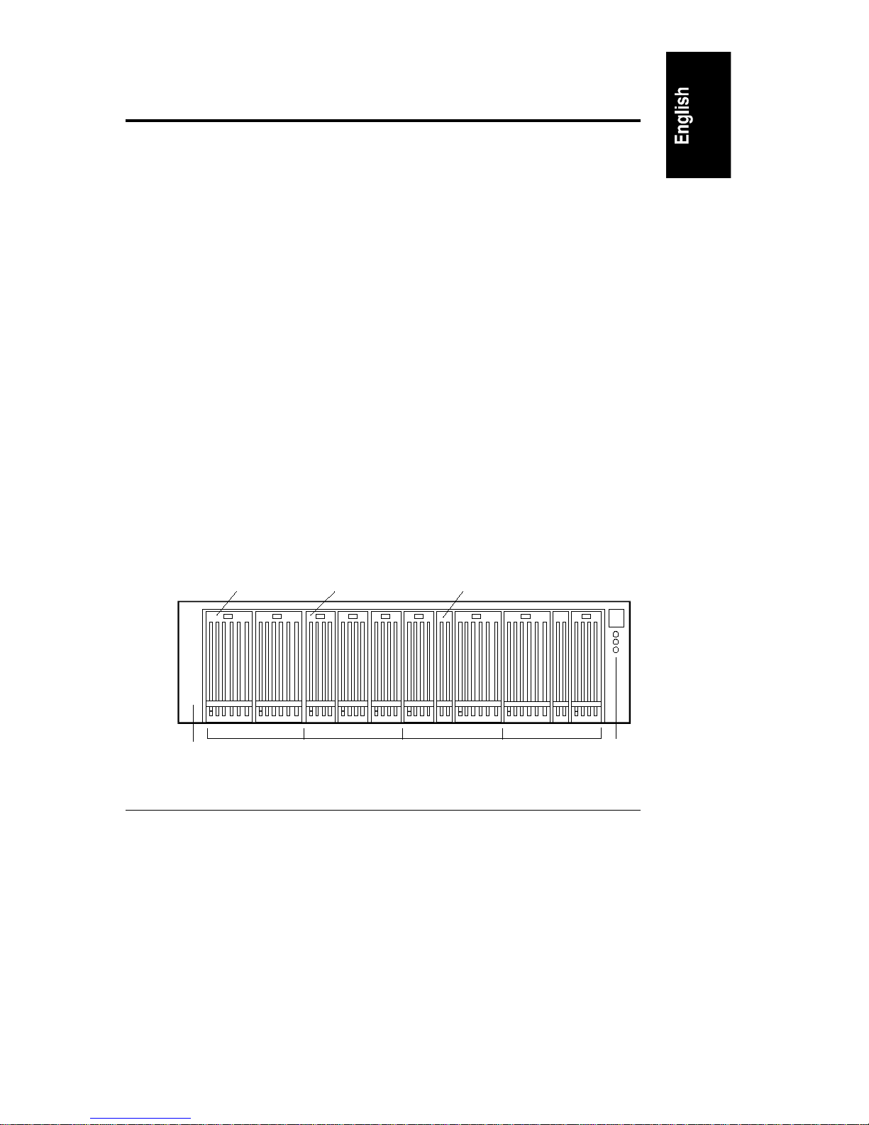
Figure 1-1 shows the front view of the HP Rack Storage/12 system with hal f
height hard drives, low profile hard drives, and drive spacers installed. The
visible components are the Status LEDs, the drive cage, and the bezel.
Bezel
Half-Height
Drive
Figure 1-1. HP Rack Storage/12 Fr ont Panel
Low-Profile
Drive
Drive Cage Sections
Drive
Spacer
Status LEDs
3
Page 10

Chapter 1 HP Rack Storage/12 Overview
Status LEDs
The three Status LEDs indicate the current operating status of the HP Rack
Storage/12.
Bezel
The bezel covers the chassis, the support rails, and the thumbscrews securing the
chassis to the support rails. The bezel clips on to the chassis and can be installed
and removed without tools.
Drive Cage
The drive cage supports the installation of 8 half-height hard drives, 12
low-profile hard drives or a combination of half-height and low profile hard
drives. Drive spacers are used between half-height and low-profile hard drives.
Filler panels in unused drive slots are mandatory to maintain proper drive
cooling.
Configurations
Internal chassis braces divide the drive cage into four sections. Each section can
support the following hard drive configurations (see Figure 1-1):
• Three low-profile hard drives
• Two half-height hard drives
• One low-profile drive, one half-height drive and one drive spacer
SCSI Channe ls
Two internal SCSI channels connect the hard drives to the RS/12 SCSI card.
Hard drives installed in the left-half of the drive cage are connected to Channel 1.
The hard drives installed in the right-half of the drive cage are connected to
Channel 2 (see Figure 1-2).
4
Page 11

Chapter 1 HP Rack Storage/12 Overview
SCSI Addresses
The SCSI ID assigned to a hard drive is determined by its position in the drive
cage. Th e SAF- T E chassis ma nagemen t p rocessor is assigned SCSI ID 5. T he
default SCSI IDs assigned to 8 half–height drives and 12 low–profile drives is
shown in Figure 1-2.
Low-Profile
Drives
Half-Hei ght
Drives
1 2 3 8 91011121314150
10 11 13 141083
Channel 1 Channel 2
Figure 1-2. Default SCSI ID Assignment
Hot-Swap Hard Drives
For the latest list of HP-tested hard drive products, refer to the "Tested Products
List" Help topic on the HP NetServer Navigator CD-ROM or the Internet Web
page:
http://www.hp.com/netserver
NOTE Do not use hard drives that are not specifically certified by
Hewlett-Packard for use in the HP Rack Storage/12.
The hard drives are multimode disk drives, which allow the integration of the
differential drivers and receivers into SCSI drive control lers. The hard dr ive
technology provides increased signal quality, and ensures the same data integrity
as the previous high voltage differential designs at a reduced cost.
The HP Rack Storage/12 hot-swap hard drives come in two heights: the 1-inch
low-profile drive and th e 1.6-inch half-heigh t drive.
5
Page 12
Chapter 1 HP Rack Storage/12 Overview
Status LED s
Each hard drive has two status indicators located in the lower left corner of the
front cover. The status indicators are drive activity and drive power. The
indicators are light pipes transmitting the output of two LEDs mounted on the
back-plane of t he dr ive cage.
Filler Panels
Filler panels are installed in unused hard drive slots in the drive cage. The 1-inch
filler panels must be inserted to ensure that drive cage has the proper air flow and
prevent excessive EMI (electromagnetic radiation). Remove the filler panel when
you install a new hard drive.
CAUTION Do not remove the filler panels except to install a new hard
dri ve. Open s lots in th e d rive cag e can affect airfl ow and
cause thermal damage and excessive EMI.
Drive Spacers
Drive spaces are required when half-height and low-profile hard drives are
installed in the drive cage. The 0.5-inch drive spacer fills the space between
adjacent drives or between a drive and a filler panel. Drive spacers can be
mounted on low-profile drives, half-height drives and filler panels. Figure 1-1
shows the use of the drive spacer between half-height and low-profile hard
drives.
CAUTION Do not remove the drive spacers except to install a new hard
dri ve. Open s lots in th e d rive cag e can affect airfl ow and
cause thermal damage and excessive EMI.
6
Page 13
Chapter 1 HP Rack Storage/12 Overview
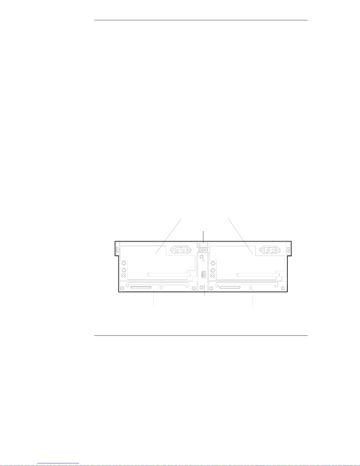
Rear View
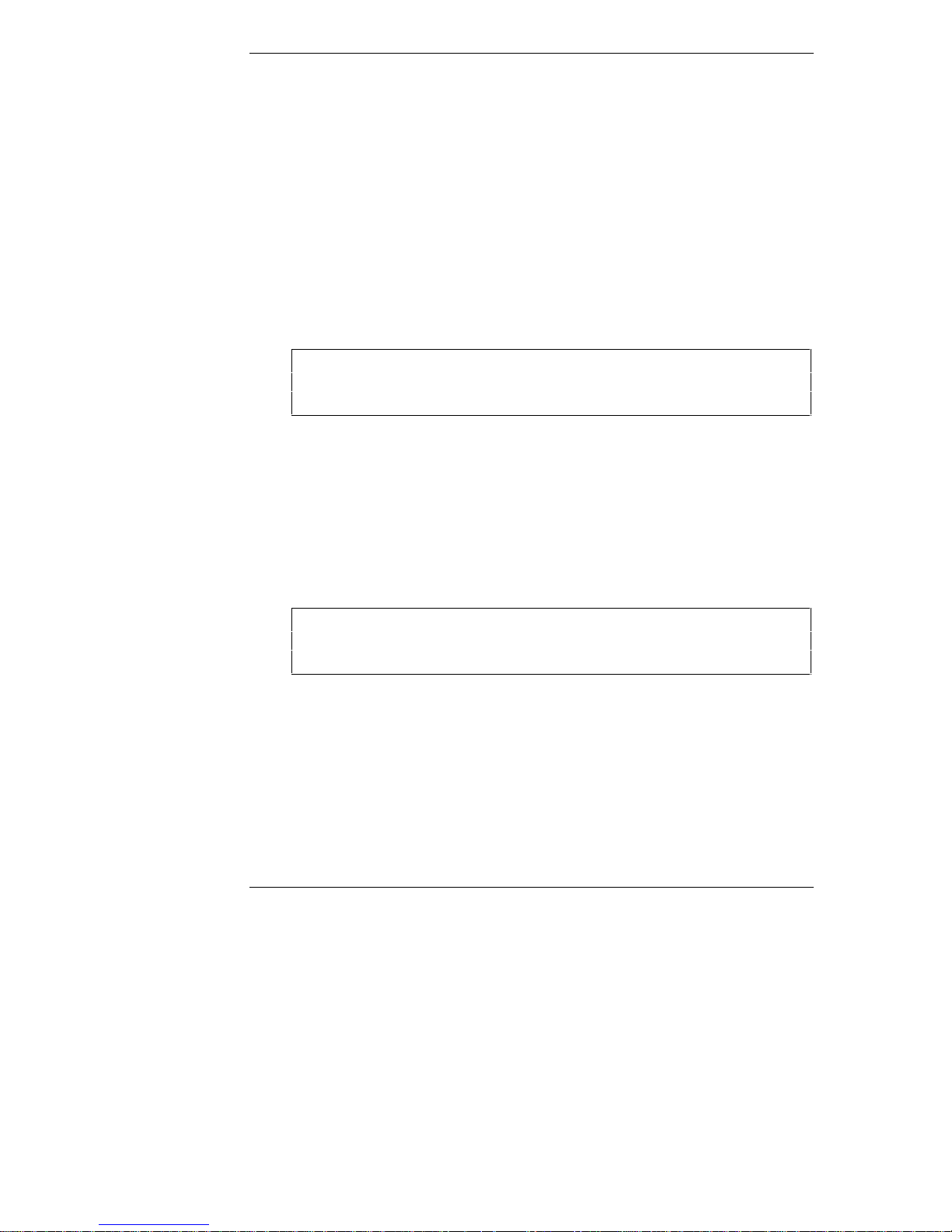
Figure 1-3 shows the rear view of the HP Rack Storage/12.
Power Supplies
Power Switch
Manageme nt Board
RS/12 SCSI Card 2
(Optional)
Figure 1-3. Rear View of t he HP Rack Storage/ 12
RS/12 SCSI Card 1
Power Switch
The power switch controls AC power to the HP Rack Storage/12. The switch is
located behind a hinged cover to prevent accidental power off.
NOTE 5 VDC standby power is supplied to the HP Rack Storage/12
even when the power switch is set OFF. T o r em ove standby
power, disconnect both power supplies from their AC sources.
7
Page 14

Chapter 1 HP Rack Storage/12 Overview
Power Supplies
Two hot-swap power supplies are installed in the HP Rack Storage/12. Each
power supply includes an attached fan module. Power supply operation is
controlled by the power switch on the rear panel of the HP Rack Storage/12.
NOTE 5 VDC standby power is supplied to the HP Rack Storage/12
even when the power switch is set OFF. T o r em ove standby
power, disconnect both power supplies from their AC sources.
The power supply provides DC power to HP Rack Storage/12 components.
Standby power and fan power are supplied through separ at e outputs. Th e power
supply adjusts to the AC power source voltage and frequency through
auto-ranging.
The power load is shared by both power supplies. If a power supply fails, the
remaining power supply provides DC power to HP Rack Storage/12 components.
CAUTION Do not operate the HP Rack Storage/12 with a open power
supply slot. The chassis can overheat and damage
components.
NOTE Replace a failed power supply as soon as possible. The HP
Rack Storage/12 should not be operated for extended time
periods with only one operating power supply.
The power supply is protected from over-temperature conditions. When this
condition occurs, the power supply is shut down. The power supply will not
operate until the condition is removed and the AC power is cycled.
Fan Module
The variable speed fan module provides cooling airflow inside the HP Rack
Storage/12 chassis. Fan speed is regulated by the Management Board by
monitoring temperature sensors inside the chassis.
DC power is supplied to each fan by a redundant connection to both power
supplies. The fan continues to operate even if the attached power supply fails.
8
Page 15

Chapter 1 HP Rack Storage/12 Overview
RS/12 SCSI Card
The hot-swap RS/12 SCSI card connect s the disk storage of the HP Rack
Storage/12 to the host system. Data transfer rates of up to 40 Mb/sec are
supported. The HP Rack Storage/12 can be configured with one (simplex
configuration) or two (duplex or cluster configuration) RS/12 SCSI cards.
SAF-TE Chassis Management
Each RS/12 SCSI card includes a management processor that supports the
SAF-TE specification. The processor is accessible th rough SCSI I D 5.
SCSI Channe ls
The two SCSI channels are enabled by auto-configuration and configuration
switches on the Management Board.
When the HP Rack Storage/12 is powered on, Auto-configuration checks for how
many RS/12 SCSI cards are installed. Simplex configuration is enabled if one
RS/12 SCSI card is installed. Duplex configuration is enabled if two RS/12 SCSI
cards are installed. The cluster configuration is enabled by Switch 1 on the
Management Board. Descriptions of Simplex, Duplex, and cluster configurations
follow. See "Management Board" for a description of the configuration switches
later in this chapter.
Configuration S ettings
The configuration of the RS/12 SCSI card is stored in memory in the HP Rack
Storage/12. When a hot-swap RS/12 SCSI card is replaced, the configuration is
restored from memory. The configuration is only reset when the HP Rack
Storage/12 is powered on.
Management Board
The hot-swap Management Board configures the HP Rack Storage/12 and
regulates the fan speed
Temperature LED
The temperature LED displays the current environmental temperature status of
components in the HP Rack System/12.
9
Page 16

Chapter 1 HP Rack Storage/12 Overview
Configuration S witche s
The ba nk of four swi tches con figur es the HP Rack S torag e/12 for non-cluster or
cluster environments.
The switches are set Left or Right. The default switch setting is Left for all
switches. The description of each switch follows:
Switch 1: Selects cluster configuration. This switch has effect only when
two RS/12 SCSI cards are installed.
Set Left for non-cluster operation.
Set Right for cluster operation.
Switch 2 is reserved.
Switch 3 is reserved.
Switch 4 is reserved.
Configuration S witch Se ttings
The configuration switches take effect when the HP Rack Storage/12 is powered
on. Changing the switch settings after power on does not change the HP Rack
Storage/12 configuration. The configuration is saved in memory and cannot be
changed until power is cycled.
10
Page 17
2 Controls, Ports, and Indicators
This chapter describes the controls, ports and indicators on the front and rear of
the HP Rack Storage/12 .
Front View
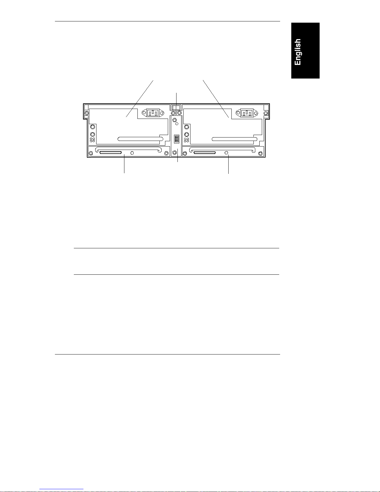
The front panel indicators are shown in Figure 2-1.
Drive Power Indicator
Drive Activity Indicator
Figure 2-1. Front Panel Indicators
ChassisStatusLEDs
Chassis Status LE Ds
The three Status LEDs indicate the current operating status of the HP Rack
Storage/12. The following conditions are displayed by the Status LEDs:
Green: Normal operation.
Flashing Yellow: Warning condition exists in the chassis. Attention is
required. Check the operating status of components on the front and rear
panels.
Flashing Red: Fault condition exists in the chassis. Immediate attention
is required. Check the operating status of all components on the front and
rear panels.
Off: No power.
11
Page 18
Chapter 2 Controls, Ports, and Indicators
Hard Driv e Status I ndicator s
Each hard drive has two status indicators located in the lower left corner of the
front cover. The status indicators are drive power and drive activity.
Drive P ower Indic ator
The drive power indicator displays the following conditions:
Off: Hard d rive n ot p resen t, or not connected to the ca g e.
Green (solid): Hard drive present.
Drive A c tivit y Indica tor
The drive activity indicator displays the following conditions:
Off: No disk activity.
Flickering Green: Accessing disk.
Flashing Yellow: Disk failure predicted.
Red: Disk fault, or drive is offline.
Rear View
The rear of the HP Rack Storage/12 is shown in Figure 2-2. Controls, ports and
indicators for each component are described separately.
Power Supplies
Power Switch
Management Board
Ultra2 SCSI Host Connector 2
Figure 2-2. Rear Panel Components
12
Ultra2 SCSI Host Connector 1
Page 19
Chapter 2 Controls, Ports, and Indicators
Power Switch
The power switch controls AC power to the HP Rack Storage/12. The switch is
located behind a hinged cover to prevent accidental power off.
NOTE 5 VDC standby power is supplied to the HP Rack Storage/12
even when the power switch is set OFF. T o r em ove standby
power, disconnect both power supplies from their AC sources.
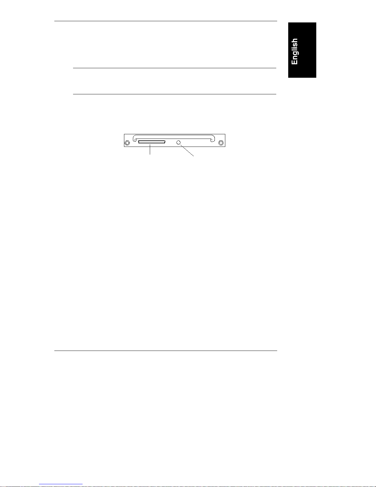
RS/12 SCSI Card
The port and indicator are shown in Figur e 2-3.
68-pin Connector
Figure 2-3. RS/12 SCSI Card Ports and Indicators
Status LED
Status LED
The Status LED indicates the current operating status of the RS/12 SCSI Card.
The following conditions are displayed by the Status LED:
Green: Normal operation.
Flashing Yellow: Firmware revision mismatch between the two installed
RS/12 SCSI car d s.
Flashing Red: Hardware fault on the RS/12 SCSI card.
Off: No power supplied to the RS/12 SCSI card.
68-Pin Conne ctor
The 68-pin h i gh-density connector connects the HP Rack Storage/12 to the host
system. SCSI bus termination is inside the HP Rack Storage/12. The host system
and the HP Rack S torag e/12 can be conn ected by external S C SI cables up to 12
meters long. External SCSI cables are not included with the HP Rack Storage/12.
Order SC SI cables fr om your HP Reseller.
13
Page 20

Chapter 2 Controls, Ports, and Indicators
Management Board
The Management Board switches and in dicators are shown in Figure 2-4.
Temperature LED
Configuration
Switches
1
2
3
4
Figure 2-4. Management Boar d Cont r ol s and Indicators
Temperature LED
The temperature LED displays the current environmental temperature status of
the HP Rack System/12.
Green: Normal operation.
Flashing Yellow: High temperature warning within the chassis. Check
fan operation, cooling, or airflow problems.
Flashing Red: Critical high temperature within the chassis. Check fan
operation, cooling, or airflow problems.
Off: No power.
14
Page 21

Chapter 2 Controls, Ports, and Indicators
A
Configuration S witche s
The ba nk of four swi tches con figur es the HP Rack S torag e/12 for non-cluster or
cluster environments.
The switches are set Left or Right. The default switch setting is Left for all
switches. The description of each switch follows:
Set Left (Default)
Switch Set Right
Non-cluster Operation 1 Cluster Operation
Reserved 2 Reserved
Reserved 3 Reserved
Reserved 4 Reserved
Power Supplies
The power supply port and indicators are shown in Figure 2-5.
C Power Connector
Power LED
Fan Status LE D
Figure 2-5. Power Suppl y Ports and I ndicators
15
Page 22

Chapter 2 Controls, Ports, and Indicators
AC Powe r C onnect or
Connects the power supply to the AC source.
Power Sta tus LED
The Power status LED displays the current operating condition of the power
supply.
Green: Normal operation.
Off: No power or power supply failure.
Fan Status LED
The fan status LED displays the current operating condition of the fan module.
Green: Normal operation.
Off: No power or fan module failure.
Operating and Managing the HP Rack Storage/12
Power On
The power switch is located on the top center of the rear panel.
NOTE 5 VDC standby power is supplied to the HP Rack Storage/12
even when the power switch is set OFF. T o r em ove standby
power, disconnect both power supplies from their AC sources.
1. Lift the hinged cover and set the power switch on.
16
Page 23

Chapter 2 Controls, Ports, and Indicators
Power Off
The power switch is located the top center of the rear panel.
1. Close all applications and log off all users using the hard drives on the
Rack Storage/12.
NOTE 5 VDC standby power is supplied to the HP Rack Storage/12
even when the power switch is set OFF. T o r em ove standby
power, disconnect both power supplies from their AC sources.
2. Lift the hinged cover and set the power switch off.
Managing Disk Arrays
HP NetServer Installation and Configuration
Refer to the HP NetServer User Guide for information on installing accessory I/O
cards and configurin g your system.
RAID Management
Refer to the HP NetRaid Series User Guide for information on HP NetRAID
adapters, network operating system requirements, and use of the HP NetRAID
configuration and management applications to configure the hard drives in the
HP Rack S torage/12.
Cluster Configur ations
Contact your Cluster Certified HP Reseller for assistance in installing your HP
NetServer and HP Rack Storage/12 in a cluster environment.
17
Page 24

Page 25

3 Installing the HP Rack Storage/12 in
a Rack
This chapter lists the steps required to install the HP Rack Storage/12 in a HP
Rack System/E, HP Rack System/U, or a HP Systems rack. If you have any other
rack type, refer to the documentation supplied with the rack for installation steps.
NOTE Read the HP NetServer Installation Roadmap before installing
the HP Rack Storage/12. Failure to perform this installation in
accordance with the Road Map could result in significant
extra installation effort.
You should plan the placement of your HP Rack Storage/12 and other rack
components before p roceeding with in stallation. For more details, see the HP
NetServer Rack Installation Road Map.
HP Rack Assistant ca n be used to plan t he rack config u ration. HP Rack Assistant
can be downloaded from the following Internet web site:
http://www.hp.com/netserver/servsup
The HP Rack Storage/12 fits into 19-inch -wide EIA (Electrical In dustry
Association) racks. The HP Rack Storage/12 requires 3 EIA units of space.
Vertical space in the rack is measured in standard EIA units. One EIA unit is
1.75 inches (44.45 mm). The space requirements and mounting hole locations
are shown in Figure 3-1.
19
Page 26

Chapter 3 Installing the HP Rack Storage/12 in a Rack
#
#
3EIA
Units
#
#
#
#
Figure 3-1. HP Rack Storage/12 Rack I nst al l ation Requirement s
EIAUnit Mark
Rack Nuts
HP Rack Storage/12
Support Rails
Rack Nuts
Tools Required
The following tool is required to install the HP Rack Storage/12:
• T25 Torx
driver
Installing Rack Nuts
The EIA unit marks are stamped in the sheet metal of the columns. Use the rack
template to locate the top and bottom of the HP Rack Storage/12 and install rack
nuts for the support rails on all four columns.
#
#
#
#
#
#
NOTE Use the prin t out from the HP Rack Assistant, a nd the
instructions from the HP NetServer Rack Installation
Roadmap to locate the HP Rack Storage/12 within the rack.
1. Hold the bottom of the rack template at the EIA unit mark.
2. Install rack nuts at the holes marked on the template (holes 1 and 6
counted up from the bottom).
3. Repeat steps 1 and 2 on all rack columns.
20
Page 27

Chapter 3 Installing the HP Rack Storage/12 in a Rack
Installing the Support Rails
Each support rail is divided into two sections. The shorter front section is secured
to the rack front column. The longer rear section is secured to the rear column
and supported in front by the extension of the front section of the rail (see
Figure 3-2).
1. Secure the front section of the support rail to the rack front column. Insert
two screws through the mounting holes and into the rack nuts mounted
earlier.
2. Slide the rear section of the support rail over the extension of the front
section. Insert two screws through the mounting holes and into the rack
nuts mounted on the rear column earlier.
Support Rails
Figure 3-2. Installing the Support Rails
3. Repeat steps 1 and 2 to mount the second support rail.
Rack Front
21
Page 28

Chapter 3 Installing the HP Rack Storage/12 in a Rack
Installing the Chassis
Install the chassis and secure it to the support rails.
WARNING Extend the anti-tip foot from the front of the rack and lower
all leveler feet to stabilize the rack before mounting rack
components. Failure to use the anti-tip foot and leveler feet
could result in injury.
1. Extend the anti-tip foot from the front of the rack and lower all leveler
feet to stabilize the rack.
WARNING Two persons are recommended to lift the HP Rack Storage/12
chassis. The chassis weighs 35 pounds (15.9 Kg) with the
power supplies removed. Installing the chassis without
assistance could result in injury to the installer.
2. Remove the power supply from the chassis to reduce the lifting weight.
NOTE The chassis top is wider than the bottom. The chassis top rests
on the support rails mounted in the rack.
3. Lift the chassis until the chassis top is above the support rails. Rest the
rear of the chassis on the support rails. Slide the chassis on the rails until
the chassis stops.
4. Secure the chassis to the support rails with two thumbscrews attached to
the rails.
22
Page 29

Chapter 3 Installing the HP Rack Storage/12 in a Rack
Thumbscrews
Bezel
Figure 3-3. Sli di ng t he Chassi s i nt o t he Rack
5. Attach the front bezel. Insert the bezel pins in the mounting holes in the
chassis front. Push the bezel until it snaps into place.
23
Page 30

Chapter 3 Installing the HP Rack Storage/12 in a Rack
Installing Components
1. Install the power supplies in the rear chassis slots. Secure each power
supply assembly with two thumbscrews (see Figure 3-4).
Management Board
RS/12 SCSI Cards
Power Supplies
Figure 3-4. Installing Com ponents
2. Install the RS/12 SCSI card in slot 1 (right slot) in the rear chassis. Secure
the adapter with two thumbscrews.
3. Install the second RS/12 SCSI card or a blank filler panel in slot 2 (left
slot) in the rear chassis. Secure with two thumbscrews.
4. Install the Management Board in the rear chassis slot. Secure with two
thumbscrews.
5. Install the hard drives, filler panels and spacers in the drive cage
according to your disk array configuration requirements (see "Replacing
Hot-Swap Hard Drives" in Chapter 5).
24
Page 31

Chapter 3 Installing the HP Rack Storage/12 in a Rack
Completing the Installation
Return to the HP NetServer Rack Installation R oadmap to complete the
installation of rack components.
When instructed to cable components, follow instructions in Chapter 4,
"Configuring th e HP Rack Storage/12."
25
Page 32

Page 33

4 Configuring the HP Rack Storage/12
This chapter lists the steps to install cabling and configure the HP Rack
Storage/12. The following configurations are described:
• Simplex Configuration
• Duplex Configuration
• Cluster Configuration
• Power Cabling
Simplex Configuration
When one RS/12 SCSI card is installed in the HP Rack Storage/12, the host
system can access up to 12 hard d i sk drives on a single SCSI ch a nnel (see
Figure 4-1).
Figure 4-1. Simplex Cable Confi gur ation Example
1. Connect the host system adapter to the RS/12 SCSI card in slot 1 (right
slot) of the HP Ra c k Storag e /12.
27
Page 34

Chapter 4 Configuring the HP Rack Storage/12
2. Set Management Board Configuration Switch 1 Left for non-cluster
conf iguration.
Complete the configuration by installing power cables shown in "Power Cabling"
later in this chapter.
Duplex Configuration
When two RS/12 SCSI card are installed in the HP Rack Storage/12 the host
system can access up to six hard disk d rives on each SCS I channel (see
Figure 4-2).
Figure 4-2. Duplex Cable Configuration Example
1. Connect the host system adapter channel to the RS/12 SCSI card in slot 1
(r ight slot) of the HP Rack Storage/12.
2. Connect the second host system adapter channel to the RS/12 SCSI card
in slot 2 (left slot) of the HP Rack Storage/ 12.
3. Set Management Board Configuration Switch 1 Left for non-cluster
conf iguration.
Complete the configuration by installing power cables shown in "Power Cabling"
later in this chapter.
28
Page 35

Chapter 4 Configuring the HP Rack Storage/12
Cluster Configuration
When the HP Rack Storag e/12 is connect ed to two host systems, each host can
access up to 12 har d di sk dr i ves on each SCSI channel (see Figure 4-3).
Figure 4-3. Cluster Configurati on Example
1. Connect one host system adapter to the RS/12 SCSI card in slot 1 (right
slot) of the HP Ra c k Storag e /12.
2. Connect the second host system adapter channel to the RS/12 SCSI card
in slot 2 (left slot) of the HP Rack Storage/ 12.
3. Set Management Board Configuration Switch 1 Right for cluster
configuration:
Complete the configuration by installing power cables shown in "Power Cabling"
in the following section.
29
Page 36

Chapter 4 Configuring the HP Rack Storage/12
Power Cabling
Figure 4-4 shows the power cabling for the HP Rack Storage/12. Your power
installation can be different because of the rack components installed and power
load requirements. Use the cable retention clips on the power supply to prevent
inadvertent disconnection.
30
Figure 4-4. Power Cabl i ng Example
Page 37

5 Removing and Installing HP Rack
Storage/12 Components
This chapter lists the steps to remove and install the following components:
• Hot-swap hard drive
• Hot-swap RS/12 SCSI card
• Hot-swap power supply
• Hot-swap management board
Replacing a Hot-Swap Hard Drive
This section lists the steps to install or replace a hot-swap hard drive in the drive
cage. Half-height and low-profile hard drives can be installed in the drive cage
with filler panels and drive spaces installed in unused drive slots.
You should plan your hard drive removal and installation steps before removing
any hard drives, drive spaces, or filler panels from the drive cage. Refer to Mass
Storage in Chapter 1 for supported hard dr ive type, configurations and
installation restrictions.
The following general tasks are required for removing and installing hard drives:
• Prepare the new hard drive by unpacking and attaching drive spacers as
required for installation.
• Remove the hard drive from the chassis if you are replacing the hard
drive.
• Remove filler panels if you are adding a new hard drive.
• Install the hard drive.
31
Page 38

Chapter 5 Removing and Installing HP Rack Storage/12 Components
Preparing the New Hard Dr ive
CAUTION Protect the drive from static electricity by leaving it in its
anti-static bag until you are ready to install it. Before
handling the drive, touch any unpainted metal surface to
discharge static electricity. When you remove the drive from
the anti-static bag, handle it only by the frame.
Do not touch th e electr ical comp onent s . Place the drive on
the anti-static bag whenever you set it down.
Hard disk drives are very susceptible to mechanical shock and
can be damaged by a drop as short as one-quarter of an inch.
Take care when unpacking and handling the drive. If the
drop would crack an egg, it will damage the drive.
1. Remove the hard drive from its anti-static container and set it on an
anti-static mat.
Attachin g a Driv e Spacer
Drive spacers are attached to the right side of the hard drive with four tabs (see
Figure 5-1). The drive space can be attached to half-height drives, low-profile
drives, and filler panels.
32
Page 39

Chapter 5 Removing and Installing HP Rack Storage/12 Components
Drive Spacer
Tabs
Figure 5-1. Attaching the Drive Spacer
1. Insert the two back tabs into the rear slots of the hard drive. Push the drive
spacer back slightly.
2. Insert the front tabs into the slots of the hard drive.
3. Press the drive spacer and hard drive together until the drive spacer is
fully seated.
Removing a Driv e Spacer
Remove a drive spacer from the adjacent hard drive if it is not required for the
installation.
1. Slide the drive spacer back slightly to the rear of the hard drive.
2. Tilt up the front of the drive spacer to disengage the front two tabs.
3. Pull the drive spacer forward slightly to disengage the back two tabs
and lift.
33
Page 40

Chapter 5 Removing and Installing HP Rack Storage/12 Components
Removing a Filler Panel
Remove a filler panel when installing a new drive in the drive cage (see
Figure 5-2).
1. Press the locking latch and insert your fingers.
2. Using your fingers, pull the filler panel straight out.
34
Figure 5-2. Removing a Filler Panel
Page 41

Chapter 5 Removing and Installing HP Rack Storage/12 Components
Removing a Hard Drive
1. Down the disk through your RAID management application.
2. Unlock the hard drive. Push the locking latch in and then pull the ejector
handle toward you (see Figure 5-3).
3. Gently pull the hard drive out to disconnect the power connection. Leave
the hard drive in the slot.
4. Wait about 30 seconds for the drive to stop spinning and th e drive heads
to park.
5. Support the bottom of the drive as you remove it. Slowly pull the drive
straight out. Do not allow the drive to fall.
6. Turn the drive slowly to its horizontal storage orientation.
7. Place the drive in an anti-static bag. Do not stack drives.
Installing a Hard Disk Driv e
Install the hard drive in the drive cage.
CAUTION Do not us e ex ces sive force to open the ejector h andle.
Excessi ve for ce can snap off the ha ndle.
1. Press the locking latch in and pull the ejector handle out as far as it can
go, as shown in Figure 5-3.
35
Page 42

Chapter 5 Removing and Installing HP Rack Storage/12 Components
Locking Tab
Ejector
Handle
Exposed
Light Pipes
Locking
Latch
Figure 5-3. Components of the Hard Dri v e
CAUTION Do not damage the light pipes when handling or installing
the hard drive. The light pipes are exposed on the rear of the
hard drive.
2. Slide the drive slowly into the drive slot until it stops (see Figure 5-4).
3. Press the ejector handle until you feel the locking latch click into place.
The hard drive power indicator displays Green when t he hard d rive is
correctly installed.
4. Install filler panels in unused drive slots.
36
Page 43

Chapter 5 Removing and Installing HP Rack Storage/12 Components
Figure 5-4. Inst al ling the Hard Drive
37
Page 44

Chapter 5 Removing and Installing HP Rack Storage/12 Components
Replacing the Hot-swap RS/12 SCSI Card
This section lists steps to remove and install the RS/12 SCSI card (see
Figure 5-5).
Thumbscrews
Figure 5-5. Replaci ng t he RS/12 SCSI Card
Removing the RS/12 SCSI Card
NOTE Follow step 1 only for simplex and duplex configurations. The
hard drives can still be accessed in cluster configurations.
1. Close all applications and log off all users on the host system using the
hard drives connected to the RS/ 1 2 SCSI ca rd.
2. Di s connect the cable conn ecting the RS/ 1 2 S C S I card t o the h ost system.
38
Page 45

Chapter 5 Removing and Installing HP Rack Storage/12 Components
3. Loosen the t wo thumbscrews securing the RS/1 2 S C S I card to the chassi s .
4. Pull the RS/12 SCSI card out of the chassis and place it in an anti-static
container.
Removing the Con nector Filler Pan el
Remove the connector filler panel if you are installing a second RS/12 SCSI card.
1. Loosen the two thumbscrews securing the adapter filler panel to the
chassis.
2. Pull the filler panel out of the chassis.
Installing th e RS/12 SCSI Card
1. Insert the RS/12 SCSI card until it is fully seated in the chassis.
2. Secure the RS/12 SCSI card to the chassis with two thumbscrews.
3. Connect the SC SI cable from t he host system to t he RS/12 SC S I card.
NOTE The current SCSI channel configuration is restored from
memory. The configuration can be changed by recycling AC
power.
Replacing the Hot-Swap Power Supply
The power supply and fan module are r emoved as a unit from the chassis (see
Figure 5-6).
NOTE The remaining power supply supplies power to the HP Rack
Storage/12 while the power supply is replaced.
Replacing the hot-swap power supply requires completing the following tasks:
• Remove the power supply
• Separate the fan module from the power supply
• Attach an operating fan module to an operating power supply
• Install the power supply
39
Page 46

Chapter 5 Removing and Installing HP Rack Storage/12 Components
Cable Retention
Clamp
Thumbscrews
Figure 5-6. Power Suppl y Assembly
Removing the Power Supply
1. Unplug the power cord from the AC source and from the power supply.
2. Loosen th e two thumbscrews securing t he power supply to the chassis.
3. Pull the power supply out of the chassis until the power supply
disconnects from its conn ector. Leave the power supply in the chassis
until the fan stops spinning.
WARNING Wait 60 seconds for the fan to stop spinning. Removing the
power supply before the fan stops can result in i njury to you
or damage to equipment.
Do not t ou ch th e exposed power connect or in side the chas s i s .
Elect rical current is present and could caus e i njury.
4. Pull the power supply out of the chassis and place it on a work surface.
40
Page 47

Chapter 5 Removing and Installing HP Rack Storage/12 Components
Separatin g the Fan M odul e from the Powe r Su pply
1. Press and hold th e plasti c tabs securing the fan to the power supply (see
Figure 5-7).
1. Press and
hold tabs
2. Push down
on fan
Figure 5-7. Separat ing the Fan Module f r om the Power Supply
2. Push down on the fan to separate the fan from the power supply.
41
Page 48

Chapter 5 Removing and Installing HP Rack Storage/12 Components
Attachin g the Fan Modu le to th e Power S upply
Attach an operating fan module to an operating power supply.
1. Hold the fan module and insert the tabs on bottom of the fan module into
the slots on the bottom of the power supply.
2. Lift the fan module until the top tabs snap into the top slots of the power
supply.
Installing th e Power Su pply
1. Insert the power supply until it is fully seated in the chassis.
2. Tighten t he two thumbscrews to secure the power supply assembly to the
chassis.
3. Plug the power cord into the power supply and int o the AC source.
4. Secure the power cord in the cable retention clamp.
5. Verify the Power and Fan status LEDs on the power supply both display
Green (normal operating mode).
42
Page 49

Chapter 5 Removing and Installing HP Rack Storage/12 Components
Replacing the Hot-Swap Management Board
The Management Board can be replace without affecting the operation of, or
access to, the disk arrays. The current HP Rack Storage/12 configuration is stored
in memory. When the replacement Management Board is installed, the current
operating configuration is unchanged. The configuration can be changed by
resetting the configuration switches and recycling AC power.
Preparin g the Replacem ent Man agemen t Board
1. Remove the Management Board from its anti-static container (see
Figure 5-8).
Thumbscrews
Configurati on Switches
Figure 5-8. Replacing the Management Board
2. Set the configuration switches on the replacement Management Board to
the settings on the Management Board currently installed in the HP Rack
Storage/12.
43
Page 50

Chapter 5 Removing and Installing HP Rack Storage/12 Components
Removing the Management Board
1. Loosen the two thumbscrews securing the Management Board to the
chassis.
2. Pull on the thumbscrews to release the Management Board from its
connect or. Remove the Managem ent Board from the ch assi s.
3. Place the Management Board in an anti-static container.
Installing th e Managemen t Board
1. Insert the Management Board into the chassis until it is fully seated.
2. Tighten the two thumbscrews to secure the Management Board to the
chassis.
Removing the HP Rack Storage/12 from the Rack
The following section lists steps to remove the chassis from the rack.
1. Close all applications and log off all users using the disk arrays on the
Rack Storage/12.
2. Lift the hinged cover and set the power switch off.
3. Disconnect all data cables and power cords.
4. Label each hard drive and filler panel so that they can be later installed in
the same location in the drive cage.
NOTE Remove components to reduce the chassis weight before
removing it from the rack.
5. Remove all hard drives and filler panels from the drive cage.
6. Remove the two power supplies.
7. Re move the front bezel.
8. Loosen two thumbscrews securing the chassis to the rack support rails.
WARNING Extend the anti-tip foot from the front of the rack and lower
all leveler feet to stabilize the rack before removing rack
components. Failure to use the anti-tip foot and leveler feet
could result in serious injury.
44
Page 51

Chapter 5 Removing and Installing HP Rack Storage/12 Components
9. Extend the anti-tip foot from the front of the rack and lower all leveler
feet to the floor.
WARNING Two persons are recommended to remove the HP Rack
Storage/12 chassis. The empty chassis weighs 35 pounds
(15.9 Kg) with power supplies removed. Removing th e
chassis without assistance could result in injury.
Support the chassis as you remove it.
10. Slide the chassis out of the rack and place it on work surface.
45
Page 52

Page 53

6 Troubleshooting
Checking for General Problems
• If the chassis status LED is flashing red, or flashing yellow, check for
failed components on the front and rear panel. Check status LEDs and
ind icators on each component.
• If the Management Board Temperature LED is flashing yellow, the
chassis is too hot. Check the following:
◊ Both HP Rack Storage/12 fans are operating.
◊ Rack cooling fans are operating.
◊ Remove obstructions in the rack that could affect airflow to the HP
Rack Storage/12.
• Check that all cables and power cords are firmly plugged into their proper
receptacles.
• Check that all parts of the system are turned on and properly adjusted.
• If the system is plugged into a switched multiple-outlet box, make sure the
switch on the outlet box is turned on.
• Plug a different electrical device (such as a printer) into the power outlet,
and turn it on.
• Always exchange units suspected of malfunctioning with another unit you
know is operable.
No System Power
• If no LEDs are lit, both power supplies are either dead or disconnected.
• If one power supply LED is green, the system can operate properly.
• If one power supply Power LED is not lit, check the following:
◊ You have properly seated the power supply in its connector.
47
Page 54

Chapter 6 Troubleshooting
◊ Ensure that all power cords are firmly plugged into the proper
receptacles.
• If the system is plugged into a switched, multiple-outlet box, make sure
the switch on the outlet box is turned to the on position.
• If the power supply still does not power up, it may be defective. Remove
and replace it with a di fferent power supply.
• Shut down the system and exchange the faulty unit with the other unit.
Restart the system and check both power supplies.
Hard Drives Not Responding
• If the OS Event Log displays device timeouts, one or more hard drives
cannot access the SCSI channel due to high system or disk activity.
Device timeouts may occur in a simplex configuration of 12 hard drives. If
timeouts occur frequently, the recommended solution is to add a second
RS/12 SCSI card and connect to the host through a duplex configuration.
• If the Drive Power Indication is not lit, check the following:
◊ Check to make sure that the HP Rack Storage/12 is powered on and
the there is power to the unit.
◊ Check that the hard drive is seated in the drive cage. Remove and
reinstall the hard drive. If the hard drive still does not spin up, replace
it with another hard drive.
• If the Drive Activity Indicator displays green for more than one minute,
the hard drive is either spinning up or has "hung." Check the drive status
through your RAID management application.
• If the Drive Activity Indicator is flashing yellow, the hard drive is
predicting a failure. Replace it with a new hard drive.
• If the Drive Activity Indicator is red, the hard drive has been marked
offline or has failed. Replace it with a new hard drive.
48
Page 55

Chapter 6 Troubleshooting
RS/12 SCSI Card Not Responding
• If the hard d rives con nected to the RS/ 1 2 SCSI ca rd cannot be accessed,
check data cable connections between the HP Rack Storage/12 and the
host system.
• If the Status LED is not lit, check that the board is properly seated in the
chassis.
• If the Status LED is yellow, verify that both installed RS/12 SCSI cards
support the sa m e SAF-TE processor revision.
• If the Status LED is red, the board is defective. Replace the board with a
new board.
Management Board Not Responding
• Check to make sure that the HP Rack Storage/12 is powered on and that
there is power to the unit.
• If the Temperature LED is not lit, remove the Management Board and
replace it with a new board.
• If the Temperature LED is flashing yellow, the chassis is too hot. Verify
that both fans are operating properly.
• If the status LED is flashing red, the chassis is too hot and auto-shutdown
is imminent. Verify that both fans are operating properly.
49
Page 56

Page 57

A ppendix A Warranty, Service and
Support
Warranty
The HP Rack Storage/12 is covered by a three-year on-site warranty. Please refer
to the HP NetServer Warranty and Service/Support Booklet included with your
product for a description of the On-Site Warranty, and for all other information
regarding Hewlett-Packard’s warranty of this product.
Service and Support
Please refer t o the HP NetServer Warranty and Service/Support Booklet included
with your HP Rack Storage/12 for all information regarding service and support
for this product.
51
Page 58

Page 59

A ppendix B Regulatory Information
Restricted Access Location
This unit is designed to be installed in a Restricted Access Location, which may
be a lockable rack or room.
Notice for USA
FCC Radio Frequ ency Emission s Statem ent
Class A Product Statement
This equipment has been tested and found to comply with the limits for a Class A
digital device, pursuant to Part 15 of the FCC Rules. These limits are designed to
provide reasonable protection against harmful interference when operating the
equipment in a commercial environment. This equipment generates and uses,
and can radiate radio frequency energy and, if not installed and used in
accordance with the instructions, may cause harmful interference to radio
communications. Operation of this equipment in a residential area is likely to
cause harmful interference in which case the user will be required to correct the
interference at his or her own expense.
Notice for Canada: DOC Requirements
This Class A digital apparatus meets all requirements of the Canadian
Interference-Causing Equipment Regulations.
Cet appareil numérique de la classe A respecte toutes les exigences du Réglement
sur le matériel brouilleur du Canada.
53
Page 60

Appendix B Regulatory Information
DECLARA TION OF CONFORMITY
per ISO/IEC Guide 22 and EN 45014
Manufacturer
Manufacturer
declares, that the product
conforms to the follow i ng Product Specifications:
Safety: IEC 950:1991 + A1+ A2 + A3 / EN 60950:1992 + A1+ A2 + A3
EMC: CISPR 22:1993 / EN 55022 (1994)
Supplementary Information:
1) The product was tested in a typical configuration with Hewlett-Packard peripherals.
2) Models were configur ed with a netwo rk interface board a n d shielded twisted-pair cable.
3) The product complies with Part 15 of the FCC rules. Operation is subject to the following two conditions:
The product herewith complies with the requirements of the following directives and carries the CE-marking accordingly:
Santa Clara, September 1, 1998
’s Name: Hewlett-Packard Company
’s Address: 5301 Stevens Creek Blvd.
Santa Clara, CA 95052 USA
Product Name: Rack Storage/12
Produ c t Options: All
EN 50081-1:1992 - Generic Emission
EN 50082-1:1992 - Generic Immunity
IEC 801-2:1991, 4 kV CD, 8 kV AD
IEC 801-3:1984, 3V/m
IEC 801-4:1988, 0.5 kV Signal Lines, 1 kV Power Lines
FCC Title 47 CFR, Par t 1 5
•
This device may not cause harmful interference, and
•
This device must accept any interference received, including interference that may cause
undesired operation
-EMC Directive 89/336/EEC
-Low Voltage Directive 73/23/EEC
Nigel Marr ion / Quality Manager
54
Page 61

A ppendix C Specifications
The specifications listed below may vary if you install a hard drive in your
storage system that has more stringent environmental limits. Make sure the
operating environment for your storage system is suitable for all the hard drive
drives that you are using.
Environment
Temperature
Operating
Non-operating
Humidity (nonc ondens ing)
Operating 20% to 80% relative humidity
Non-operating Maximum 95% relative humidity
Altitude
Operating 3,046 m (10,000 ft)
Non-operating 12,200 m (40,000 ft)
Weight and D ime nsions
Height 13.2 cm (5.19 in)
Width 46.36 cm (18.25 in)
Depth 71. 76 cm (28.25 i n)
Weight, chassis fully loaded 37.7 kg (83 lb)
Weight, chassis empty 15.9 kg (35 lb)
5° to 35° C (40° to 95° F)
–40° to 65° C (-40° to -140° F)
55
Page 62

Appendix C Specifications
Power Requirements
Input voltage range 90-264 VAC
Frequency 47-63 Hz.
Typical AC input requirements for fully loaded configuration (73% of power
supply capability):
Nominal Volts Amps Watts
100 5.48 537
120 4.51 530
200 2.61 512
230 2.25 507
Power supply type Wide input range, power factor corrected
DC output power 500 Watts DC, continuous, maximum
Peak AC inrush current 30 Amps @ 230 VAC
56
Page 63

Index
A
ambient temperature, 1
B
bezel, 4
C
cabling
cluster, 29
duplex, 28
power, 30
SCSI limits, 13
simplex, 27
CAUTION
damaging hard drive light pipes, 36
damaging hard drives, 32
disk ejector h andle, 35
dri ve sp acer us e, 6
filler panel use, 6
open power supply slot, 8
static electricity, 32
chassis
dimensions, 19
installing, 22
removing from rack, 44
status LED, 11
circuit overloading, 1
cluster
cabling, 29
configuring, 9, 17
definiton, 3
switch setting, 10, 14
configuration
resetting, 9, 10
restoring, 9
switch settings, 43
switches, 9
D
data transfer rate, 9
drive
activity in dicator, 12
power indication, 12
spacers, 6
drive cage, 4
capacity, 4
sections, 4
dri ve sp acers
definiton, 4
installing, 32
removing, 33
duplex
auto-configuration, 9
cabling, 28
definiton, 3
switch settings, 14
E
environmental specifications, 55
F
fan
attaching to power supply, 42
replacing, 39
separating from power supply, 41
fan module, 8
fan status LED, 16
filler panel
definition, 6
removing, 34
G
grounding, 1
H
half-height drives, 5
hard drive
57
Page 64

Index
addressing, 5
certified products, 5
configurations, 4
filler panel, 6
half-height, 5
installing, 35
low-profile, 5
removing, 35
replacing, 31
spacers, 6
status, 12
status indicators, 6
troubleshooting problems, 48
types, 4
HP NetServe r, 3
I
installation
components, 2 4
rack nuts, 20
requirements, 19
support rails, 21
L
low-profile hard drives, 5
M
management board
definition, 9
installing, 44
replacing, 43
switches, 9, 1 4
temperature LED, 14
troubleshooting problems, 49
mass storage, 3
N
Navigator
CD-ROM, 5
NetServer
installing and configuring, 17
P
power
cabling, 30
fan status LED, 16
over temperature protection, 8
powering off, 17
powering on, 16
redundancy, 8
requirements, 56
standby, 7
status LED, 16
supply, instaling, 42
supply, replacing, 39
switch, 7, 13
troubleshooting problems, 47
R
Rack Assistant, 20
rack nuts, 20
rack space requirements, 19
RAID managing, 17
Roadmap, 20
RS/12 SCSI Card, 9
conn ector, 1 3
installing, 39
replacing, 38
status LED, 13
troubleshooting problems, 49
S
SAF-TE
Addressing, 5
processor, 5, 9
SCSI
Addressing, 5
cable limit, 13
channels, 4, 9
conn ector, 1 3
default addressing, 5
servicing
fan , 39
hard drive, 31
58
Page 65

Index
power supply, 39
RS/12 SCSI card, 38
simplex
auto-configuration, 9
cabling, 27
definiton, 3
switch settings, 14
Small Computer System Interface, 3
specifications, 55
status
chassis, 1 1
chassis temperature, 14
fan , 16
hard drive, 6, 12
management board, 9
power, 16
RS/12 SCSI Card, 13
support
rails, 21
T
troubleshooting
hard drive problems, 48
management board problems, 49
power problems, 47
RS/12 SCSI card problems, 49
W
WARNING
fan removal, 40
lifting chassis, 22, 45
power supply connector, 40
stabilizing rack, 22, 44
weight and dimensions, 55
59
 Loading...