

Page 1

HP Uninterruptible Power System
R6000 Models
User Guide
December 2002 (Third Edition)
Part Number 347223-003
Page 2

© 1998, 2002 Hewlett-Packard Development Company, L.P.
Hewlett-Packard Company shall not be liable for technical or editorial errors or omissions contained herein. The
information in this document is provided “as is” without warranty of any kind and is subject to change without
notice. The warranties for HP products are set forth in the express limited warranty statements accompanying such
products. Nothing herein should be construed as constituting an additional warranty.
HP Uninterruptible Power System R6000 Models User Guide
December 2002 (Third Edition)
Part Number 347223-003
Page 3

Contents
About This Guide
Intended Audience...................................................................................................................................... vii
Important Safety Information .....................................................................................................................vii
Symbols on Equipment............................................................................................................................... vii
Rack Stability.............................................................................................................................................viii
Symbols in Text......................................................................................................................................... viii
Text Conventions....................................................................................................................................... viii
Related Documents...................................................................................................................................... ix
Getting Help................................................................................................................................................. ix
HP Technical Support ........................................................................................................................... ix
HP Website............................................................................................................................................ ix
HP Authorized Reseller.......................................................................................................................... x
Reader’s Comments...................................................................................................................................... x
Chapter 1
Overview
UPS Features .............................................................................................................................................1-1
Communications Ports ........................................................................................................................1-1
UPS R6000 Models ...................................................................................................................................1-2
Front Panel ..........................................................................................................................................1-2
Rear Panel ...........................................................................................................................................1-3
Power Management Software.................................................................................................................... 1-5
UPS Hardware Options.............................................................................................................................. 1-5
UPS Option Cards............................................................................................................................... 1-6
Extended Runtime Modules.............................................................................................................. 1-10
Remote Emergency Power Off Port ........................................................................................................1-11
Warranties................................................................................................................................................ 1-11
$25,000 Computer Load Protection Guarantee................................................................................. 1-11
Pre-Failure Battery Warranty............................................................................................................1-11
Chapter 2
Operation
Front Panel Controls and LCD Display..................................................................................................... 2-1
Front Panel Indicators................................................................................................................................2-2
Front Panel LCD .................................................................................................................................2-2
Front Panel LEDs................................................................................................................................ 2-3
Modes of Operation ................................................................................................................................... 2-3
Charging the Batteries ...............................................................................................................................2-5
Placing the UPS in Operate Mode............................................................................................................. 2-5
HP Uninterruptible Power System R6000 Models User Guide iii
Page 4

Contents
Initiating a Self-Test.................................................................................................................................. 2-6
Audible Alarms ......................................................................................................................................... 2-6
Silencing an Audible Alarm ............................................................................................................... 2-7
Shutting Down the System........................................................................................................................ 2-7
Chapter 3
LCD Configuration and Status
Changing Configuration Parameters ......................................................................................................... 3-1
Matching the Utility Voltage..................................................................................................................... 3-2
LCD Display Menu Structure.................................................................................................................... 3-3
Initial Power-Up Display .......................................................................................................................... 3-3
Top Level Main Menu............................................................................................................................... 3-3
Menu Map........................................................................................................................................... 3-4
Status................................................................................................................................................... 3-5
Meters ................................................................................................................................................. 3-6
Active Alarms..................................................................................................................................... 3-7
Battery Data........................................................................................................................................ 3-8
Firmware Version ............................................................................................................................... 3-8
Load Control....................................................................................................................................... 3-9
Display Test........................................................................................................................................ 3-9
System Setup .................................................................................................................................... 3-10
Chapter 4
Battery Maintenance
Precautions ................................................................................................................................................ 4-1
Charging Batteries..................................................................................................................................... 4-1
Determining When to Replace Batteries................................................................................................... 4-2
Obtaining New Batteries........................................................................................................................... 4-2
Replacing the Batteries.............................................................................................................................. 4-2
Removing the Battery Pack ................................................................................................................ 4-3
Installing a New Battery Pack ............................................................................................................ 4-6
Testing the New Battery Pack ............................................................................................................ 4-6
Disposing of Used Batteries...................................................................................................................... 4-7
Care and Storage of Batteries.................................................................................................................... 4-7
Pre-Failure Battery Warranty.............................................................................................................. 4-8
Chapter 5
Troubleshooting
Responding to Audible Alarms................................................................................................................. 5-1
Trouble Indicators ..................................................................................................................................... 5-4
LED Alarm Configurations....................................................................................................................... 5-4
Repairing the UPS..................................................................................................................................... 5-5
iv HP Uninterruptible Power System R6000 Models User Guide
Page 5

Appendix A
Regulatory Compliance Notices
Regulatory Compliance Serial Numbers ..................................................................................................A-1
Federal Communications Commission Notice ......................................................................................... A-1
Class A Equipment............................................................................................................................. A-1
Class B Equipment............................................................................................................................. A-2
Declaration of Conformity for Products Marked with the FCC Logo, United States Only............... A-2
Modifications ..................................................................................................................................... A-2
Cables................................................................................................................................................. A-3
Canadian Notice (Avis Canadien) ............................................................................................................ A-3
Class A Equipment............................................................................................................................. A-3
Class B Equipment............................................................................................................................. A-3
European Union Notice ............................................................................................................................ A-3
Japanese Notice ........................................................................................................................................A-4
BSMI Notice............................................................................................................................................. A-4
Battery Replacement Notice..................................................................................................................... A-5
Appendix B
Electrostatic Discharge
Preventing Electrostatic Damage.............................................................................................................. B-1
Grounding Methods To Prevent Electrostatic Damage ............................................................................ B-1
Contents
Appendix C
Specifications
Physical Specifications............................................................................................................................. C-1
Input Specifications .................................................................................................................................. C-1
Output Specifications................................................................................................................................ C-2
Battery Specifications............................................................................................................................... C-3
Battery Runtime........................................................................................................................................ C-4
Environmental Specifications................................................................................................................... C-4
Index
HP Uninterruptible Power System R6000 Models User Guide v
Page 6
This guide provides information about operation, configuration, battery maintenance, and
troubleshooting for the UPS.
Intended Audience
This guide is intended for individuals requiring information about the use of UPSs. No
installation or service procedure should be carried out by someone other than a technician
with specific experience with high-voltage equipment.
Important Safety Information
Before installing this product, read the Important Safety Information document provided.
About This Guide
Symbols on Equipment
The following symbols may be placed on equipment to indicate the presence of potentially
hazardous conditions.
WARNING: This symbol, in conjunction with any of the following symbols, indicates
the presence of a potential hazard. The potential for injury exists if warnings are not
observed. Consult your documentation for specific details.
This symbol indicates the presence of hazardous energy circuits or electric shock
hazards. Refer all servicing to qualified personnel.
WARNING: To prevent injury from electric shock hazards, do not open this enclosure.
Refer all maintenance, upgrades, and servicing to qualified personnel.
This symbol indicates that the component exceeds the recommended weight for
one individual to handle safely.
Weight in kg
Weight in lb
WARNING: To prevent personal injury or damage to the equipment, observe
local occupational health and safety requirements and guidelines for manual
material handling.
HP Uninterruptible Power System R6000 Models User Guide vii
Page 7
About This Guide
Rack Stability
WARNING: To prevent personal injury or damage to the equipment, verify that:
• The leveling feet are extended to the floor.
• The full weight of the rack rests on the leveling feet.
• The stabilizing feet are attached to the rack if it is a single-rack installation.
• The racks are coupled together if it is a multiple-rack installation.
• Extend only one component at a time. A rack may become unstable if more than
Symbols in Text
These symbols may be found in the text of this guide. They have the following meanings.
WARNING: Text set off in this manner indicates that failure to follow directions in the
warning could result in bodily harm or loss of life.
CAUTION: Text set off in this manner indicates that failure to follow directions could result in
damage to equipment or loss of information.
one component is extended for any reason.
IMPORTANT: Text set off in this manner presents clarifying information or specific instructions.
NOTE: Text set off in this manner presents commentary, sidelights, or interesting points of information.
Text Conventions
This document uses the following conventions:
• Italic type is used for complete titles of published guides or variables. Variables include
information that varies in system output, in command lines, and in command parameters
in text.
• Bold type is used for emphasis, for onscreen interface components (window titles, menu
names and selections, button and icon names, and so on), and for keyboard keys.
• Monospace typeface is used for command lines, code examples, screen displays,
error messages, and user input.
• Sans serif typeface is used for uniform resource locators (URLs).
viii HP Uninterruptible Power System R6000 Models User Guide
Page 8

Related Documents
For additional information on the topics covered in this guide, refer to the following
documents:
• HP Uninterruptible Power System R6000 Models Installation Instructions
• HP UPS R6000 Models Extended Runtime Module Installation Instructions
• HP Power Products Glossary
Getting Help
If you have a problem and have exhausted the information in this guide, further information
and other help is available in the following locations.
HP Technical Support
For telephone numbers of worldwide Technical Support Centers, go to www.hp.com.
About This Guide
HP Website
Have the following information available before you call:
• Technical support registration number (if applicable)
• Product serial number
• Product model name and number
• Applicable error messages
• Add-on boards or hardware
• Third-party hardware or software
• Operating system type and revision level
• Power management software type and version
For information on this product as well as the latest drivers, firmware, and service packs, go
www.hp.com.
to
HP Uninterruptible Power System R6000 Models User Guide ix
Page 9

About This Guide
HP Authorized Reseller
For the name of your nearest HP authorized reseller:
• In the United States, call 1-800-345-1518.
• In Canada, call 1-800-263-5868.
• Elsewhere, see the HP website for locations and telephone numbers.
Reader’s Comments
To comment on this guide, send an email to ServerDocumentation@hp.com.
x HP Uninterruptible Power System R6000 Models User Guide
Page 10

This chapter contains a general overview of the UPS, including an introduction to the model
configuration, power management software, available hardware options, and warranties. Read
this chapter to become familiar with the features of the UPS before installing the unit.
UPS Features
The following features make this UPS versatile and easy to use:
• Two serial communications ports
• Five independent load segments (including three 16 A IEC-320 receptacles and 12 10 A
IEC-320 receptacles)
• Front panel controls and LCD display for easy configuration, monitoring, and operation
• Expanded support for power management software
1
Overview
• Support for HP Extended Runtime Modules (ERMs)
• Support for HP Power Distribution Units (PDUs)
• Support for hardware option cards that extend the power management capabilities of the
UPS
— Multi-Server UPS Card
— Scalable UPS Card
— SNMP-EN Adapter
• Support for Remote Emergency Power Off (REPO)
Communications Ports
The UPS includes two communications ports (Port 1 and Port 2) that allow data exchange
with host computers.
CAUTION: Use only the DE9 cables supplied by HP to connect the communications port to
the host computer. Use of standard RS-232 cables may cause equipment damage.
HP Uninterruptible Power System R6000 Models User Guide 1-1
Page 11
Overview
UPS R6000 Models
The UPS R6000 includes the following models:
Table 1-1: UPS R6000 Models
Front Panel
UPS
Model
R6000 347207-001 North American, high-voltage, rack-mounted UPS
R6000j 347207-291 Japanese, high-voltage, rack-mounted UPS
R6000i 347207-B31 International, high-voltage, rack-mounted UPS
Note: The Series Number for the UPS R6000 is EO3001, followed by the
model type.
Part
Number
Comments
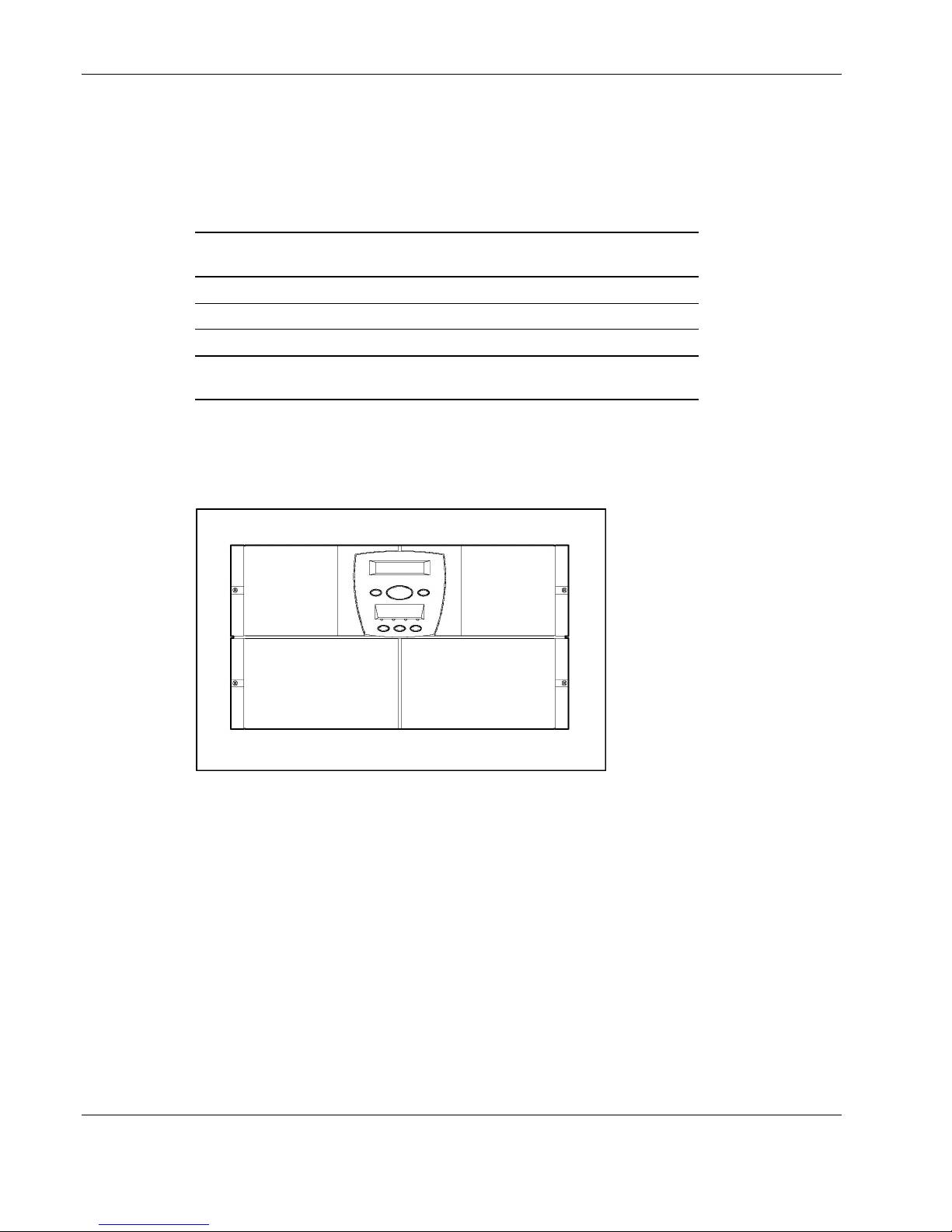
The front view of the UPS is shown in Figure 1-1.
Figure 1-1: Front panel configuration
For detailed information on using the control buttons and LED indicators, refer to the section,
“Front Panel Controls and LED Display,” in Chapter 2.
1-2 HP Uninterruptible Power System R6000 Models User Guide
Page 12
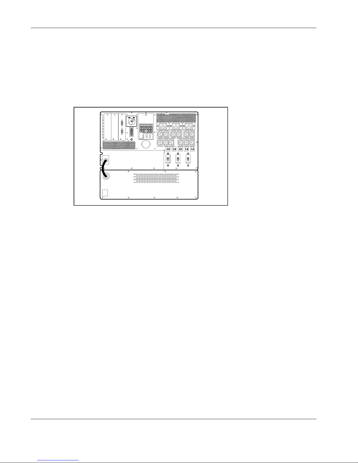
Rear Panel
Overview
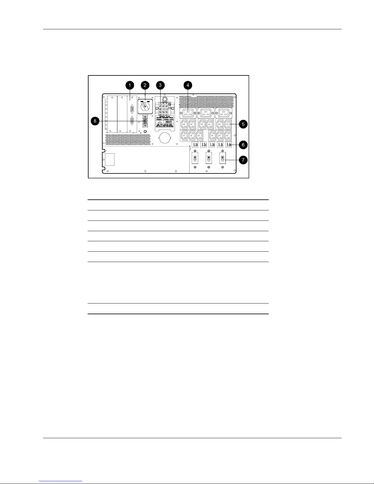
The rear panel configuration of the UPS is shown in Figure 1-2 and Figure 1-3.
Figure 1-2: Rear panel configuration
Item Description
1 Communications ports
2 Manual Bypass switch
3 Input terminal block
4 16 A receptacles
5 10 A receptacles
6 Circuit breakers for segments (left to right) 1, 2, 3, 4, and 5
7 Circuit breakers for (left to right)
• Segments 1 and 4
• Segment 2
• Segments 3 and 5
8 REPO port
HP Uninterruptible Power System R6000 Models User Guide 1-3
Page 13
Overview
Figure 1-3: Rear panel, showing numbered load segments
Item Description
1 Load segment 1 (two IEC-320-C14 receptacles and one IEC-320-C20 receptacle)
2 Load segment 2 (two IEC-320-C14 receptacles and one IEC-320-C20 receptacle)
3 Load segment 3 (two IEC-320-C14 receptacles and one IEC-320-C20 receptacle)
4 Load segment 4 (three IEC-320-C14 receptacles)
5 Load segment 5 (three IEC-320-C14 receptacles)
1-4 HP Uninterruptible Power System R6000 Models User Guide
Page 14

Power Management Software
Power management software ensures maximum power reliability of computer systems
through comprehensive control of UPSs. Specifically, power management software:
IMPORTANT: Not all UPSs are equipped to support the entire feature set listed below.
• Manages graceful shutdown of attached equipment during utility power failures.
• Manages independent UPS load segments to provide separate power control of connected
equipment.
• Prioritizes the timing of equipment shutdowns, and reboots connected equipment by load
segment.
• Shuts down and reboots any UPS and attached equipment, based on a user specified
schedule.
• Delays restart by load segment after a power outage to sequence the startup of system
components.
• Customizes alert generation with modifiable pop-up dialog boxes, command execution,
and email and broadcast messages.
Overview
• Monitors the status of the UPS and performs UPS diagnostics.
• Displays power log for analysis.
For more information, refer to the power management CD provided with the UPS. For the
most current information, refer to
UPS Hardware Options
Table 1-2 lists the available hardware options for this UPS.
Table 1-2: Hardware Options
Option Part Number
ERM 347224-B21
SNMP-EN Adapter 347225-B21
Multi-Server UPS Card 123508-B21
Scalable UPS Card 123509-B21
PDU High Voltage Models
High to Low Voltage Transformer (250 V) 388643-B21
www.hp.com.
NA Only295363-002
INTL295363-B31
HP Uninterruptible Power System R6000 Models User Guide 1-5
Page 15

Overview
UPS Option Cards
Two option slots are available to further expand the capabilities of the UPS R6000 in both
power control and server communication for networking environments. HP option kits
include the Multi-Server UPS Card, the Scalable UPS Card, and the SNMP-EN Adapter.
These enhancements provide communication with multiple systems, multiple UPS units, and
network management applications.
Option kits can be used in the following configurations:
Table 1-3: Option Card Matrix
Case Slot Multi-Server Scalable SNMP-EN
Adapter
1 1 X
2
2 1 X
2 X
3 1 X
2
4 1 X
2 X
5 1 X
2
Note: Board combinations can be used in the primary UPS only. When UPS units are chained, no
additional boards can be used in the other units.
For installation instructions, refer to the documentation shipped with the option card kits.
Direct Connect Result
(no PDU)
3 servers managing a total of
5 load segments
5 servers managing a total of
5 load segments
1 server managing a total of
9 load segments
1 in-band connection managing
a total of 9 load segments
1 in-band connection managing
a total of 5 load segments
1-6 HP Uninterruptible Power System R6000 Models User Guide
Page 16
Multi-Server UPS Card
Without a Multi-Server UPS Card, the UPS can communicate with two host computers. The
Multi-Server UPS Card enables one UPS to communicate with up to four host computers by
using all three ports on the option card and the open port on the UPS.
NOTE: Port 1 connects the card to the UPS through the pigtail cable on the card.
Overview
Figure 1-4: Multi-Server UPS Card
Power management software enables a single UPS with one Multi-Server UPS Card to
protect up to four servers. If two Multi-Server UPS Cards are installed, five servers can be
separately protected by connecting the servers to different UPS R6000 load segments.
If a network includes five servers running three different operating systems, two Multi-Server
Cards communicate directly between the UPS and all five servers. Each server and its
associated devices can be powered from a different UPS load segment.
HP Uninterruptible Power System R6000 Models User Guide 1-7
Page 17
Overview
Scalable UPS Card
The Scalable UPS Card enables up to three UPSs to be recognized as a single virtual UPS to
the host computer. Power management software allows the capability to scale up the level of
power protection available to the system.
For example, connecting three UPS R6000 units to one Scalable UPS Card creates a virtual
18 kVA UPS. The virtual UPS would have nine independently controlled load segments.
Figure 1-5: Scalable UPS Card
1-8 HP Uninterruptible Power System R6000 Models User Guide
Page 18
SNMP-EN Adapter
The SNMP-EN Adapter is a user interface to the UPS in a network where SNMP-based
network management software, such as OnliNet, is installed. Using the SNMP-EN Adapter
communication interface, system administrators can virtually eliminate costly downtime due
to power outages and surges. Spontaneous rebooting, lost files, corrupted data, and other
issues resulting from inconsistent power are decreased. The SNMP-EN Adapter provides the
means to quickly ascertain if a power-related problem exists anywhere on the network.
The SNMP-EN Adapter allows network monitoring without the need to run power
management software on a server. Other network components, such as hubs and routers, can
be monitored when power management software is not in use.
The SNMP-EN Adapter Kit includes OnliNet software and documentation, as well as
information on installing and configuring the SNMP-EN Adapter using MIB and Power MIB.
Overview
Figure 1-6: SNMP-EN Adapter
HP Uninterruptible Power System R6000 Models User Guide 1-9
Page 19
Overview
Extended Runtime Modules
The UPS R6000 rear panel provides a power receptacle to which ERMs can attach. Each
ERM contains battery packs in a 3U chassis.
At the recommended 80 percent load, one ERM extends the available UPS runtime by up to
18 minutes. Two ERMs can be serially connected to each UPS, increasing the total available
runtime by up to 30 minutes.
Figure 1-7: Back panel with installed ERM
Power Distribution Units
Extend the capabilities of the UPS R6000 by attaching a PDU to the high current receptacle
associated with load segments 1, 2, or 3. One PDU provides 12 additional receptacles to load
segments to which it is attached.
The High to Low Voltage Transformer (250 VA) can be connected to the UPS R6000 to
supply two low-voltage outlets at 250 VA.
To connect devices to the PDU, use IEC-320 jumper cords (Part No. 295633-B21). Two are
provided with the PDU kit.
1-10 HP Uninterruptible Power System R6000 Models User Guide
Page 20

Remote Emergency Power Off Port
The UPS includes an isolated REPO port. When properly wired, the REPO feature allows the
power at the UPS output receptacles to be switched off from a remote location. To use this
feature, the REPO port must be connected to a remote, normally open switch (not supplied).
When this switch is closed, the UPS immediately disconnects power to its loads. The REPO
switch is used in conjunction with a main disconnect device that removes the AC source from
the input of the UPS. To power down the entire network in the event of an emergency, the
REPO ports of multiple UPS units can be connected to a single switch.
IMPORTANT:
• The REPO port meets the requirements of NFPA Articles 645-10 and 645-11 for a Disconnecting
Means.
• If the remote switch is closed, the REPO feature immediately powers down protected devices and
does not utilize the orderly shutdown procedure initiated by power management software.
• The REPO feature shuts down UPS units operating under either utility or battery power.
• If the UPS was operating on battery power when the remote switch was closed, no power will be
available to the devices until utility power is restored and the UPS has been manually powered up.
Overview
Warranties
To back up the wide range of features offered with the UPS, a three-year limited warranty is
provided.
$25,000 Computer Load Protection Guarantee
In addition to the limited warranty, a $25,000 Computer Load Protection Guarantee (provided
by the original equipment manufacturer) is offered.
IMPORTANT: The $25,000 Computer Load Protection Guarantee is offered only in North America.
The $25,000 Computer Load Protection Guarantee applies only if:
• A qualified electrician properly connects the UPS to utility power.
• The UPS installation complies with all applicable electrical and safety codes specified by
the National Electrical Code (NEC).
• The UPS is used under normal operating conditions. Users must comply with all
instructions and labels.
• The UPS is not damaged by accident (other than a utility power transient), misuse, or
abuse.
Pre-Failure Battery Warranty
Refer to the section, “Pre-Failure Battery Warranty,” in Chapter 4 for specific information on
the battery warranty.
HP Uninterruptible Power System R6000 Models User Guide 1-11
Page 21
This chapter contains information on operating the UPS. Topics include using the front panel
controls, LCD display, LED indicators, and modes of operation. Knowledge of these features
is helpful when configuring the system and performing more advanced functions on the unit.
NOTE: Refer to the instructions included with the UPS kit for installation considerations and
procedures. Copies of this document can be downloaded from the HP website at www.hp.com.
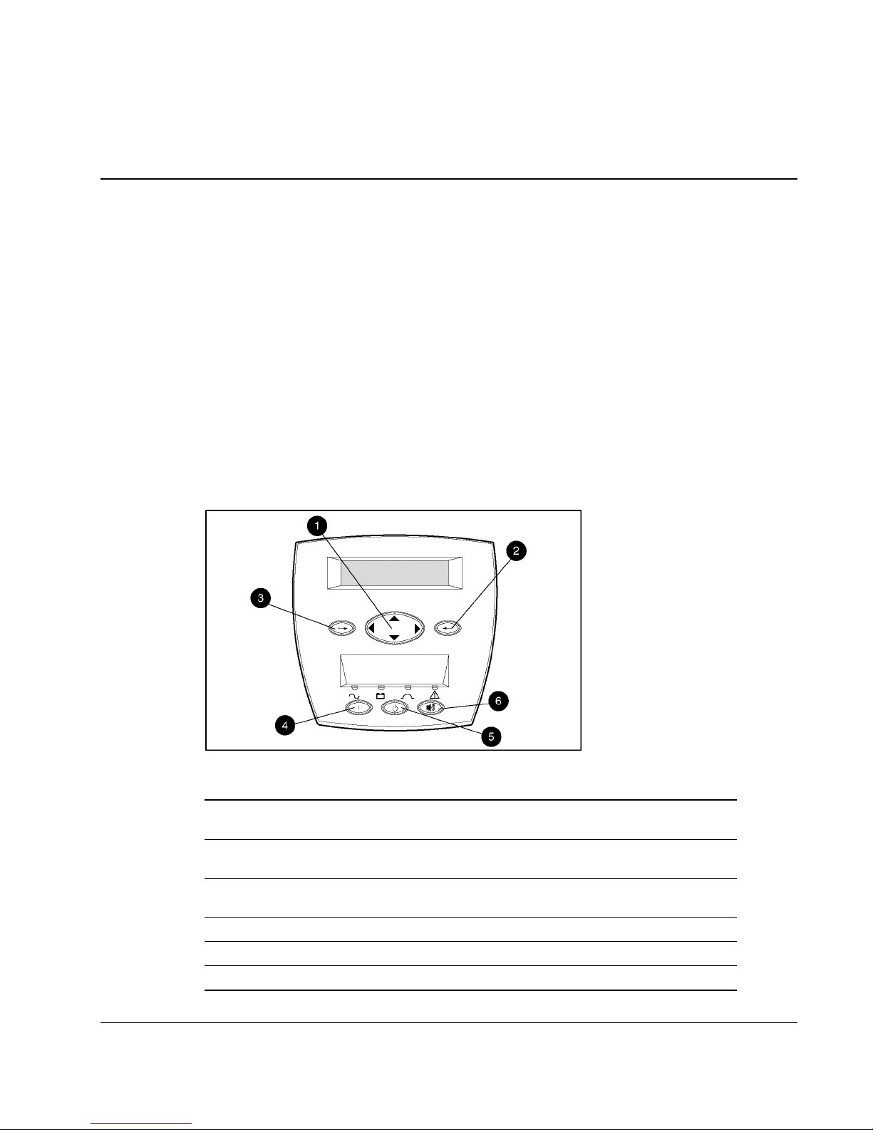
Front Panel Controls and LCD Display
The front panel controls and LCD display provide an easy-to-use UPS interface for setup,
load control, and status monitoring.
2
Operation
Figure 2-1: Front panel control buttons
Item Description Function
1 Center Large four-way rocking button used to control navigation
2 Enter Used to navigate and select options in the LCD menu
3 Escape Used to navigate and deselect options in the LCD menu
4 On Starts UPS powering the load
5 Standby Places UPS into Standby mode/Reset
6 Test/Alarm Reset Resets alarm or initiates self-test
HP Uninterruptible Power System R6000 Models User Guide 2-1
through LCD menu structure: up, down, left, and right
structure
structure
Page 22

Operation
Front Panel Indicators
The UPS displays information through the following indicators:
• Front panel LCD
• Front panel LEDs
Front Panel LCD
The front panel has a two-line LCD display (1) that displays information about operation,
configuration, and monitoring of the UPS. Refer to the section, “Changing Configuration
Parameters,” in Chapter 3 for configuration instructions.
Figure 2-2: Front panel LCD display
2-2 HP Uninterruptible Power System R6000 Models User Guide
Page 23

Front Panel LEDs
The front panel has four LEDs that indicate the status of the UPS.
Figure 2-3: Front panel LED display
LED Symbol Color Meaning
Operation
1
2
3
4
Modes of Operation
The UPS has five modes of operation:
• Standby Mode
— On Utility Power:
— On Battery Power:
— Power is not available at the UPS output receptacles.
— The UPS monitors and charges batteries if required.
• Operate Mode
— The
LED is solid green.
Green
Yellow
Yellow
Red
Solid greenNormal operation
Flashing greenStandby mode (batteries charging)
Solid yellowOn Battery
Solid yellowOn Bypass
Flashing redOne or more alarms may be present or
active
LED is flashing green.
LED is flashing yellow.
— Power is available at the UPS output receptacles.
— The UPS monitors and charges batteries if required.
HP Uninterruptible Power System R6000 Models User Guide 2-3
Page 24

Operation
• Bypass Mode
— The
LED is solid green, the LED is solid yellow, and an audible alarm is
active in five-second intervals.
— Power is available at the UPS output receptacles.
— Batteries are not monitored or charged.
— Bypass mode can be enabled by moving the Bypass switch on the UPS rear panel
from Normal to Bypass.
Figure 2-4: Placing the UPS in Bypass mode
• Battery Mode
— The
LED is solid yellow.
— Batteries are not being charged.
— Power is available at UPS outputs.
— The shutdown process has begun.
• Sleep Mode
— All LEDs are off.
— Sleep mode is optional and can be enabled or disabled using the LCD menu. The
default value for Sleep mode is
disabled. If Sleep mode is enabled, the UPS shuts
down when it is on battery power and the load is less than eight percent.
— Power is automatically restored to the output receptacles when utility power is
restored.
2-4 HP Uninterruptible Power System R6000 Models User Guide
Page 25

Charging the Batteries
When the UPS is in Standby mode, allow the batteries to charge before putting the UPS into
service.
IMPORTANT: The battery modules will charge to:
• Ninety percent of their capacity within 4 hours
• One hundred percent of their capacity within 24 hours
Allow the batteries to charge for at least 24 hours before supplying backup power to your devices.
Placing the UPS in Operate Mode
Press the On button (1) to transfer the system to Operate mode.
Operation
Figure 2-5: On button
HP Uninterruptible Power System R6000 Models User Guide 2-5
Page 26

Operation
Initiating a Self-Test
To initiate a self-test, press and hold the Test/Alarm Reset button (1) for three seconds.
Figure 2-6: Test/Alarm Reset button
Because a portion of the self-test requires battery power, the self-test will not be initiated if
the batteries are less than 90 percent charged. If the UPS detects a problem, the
illuminates solid red, and an audible alarm may sound.
NOTE: Refer to Chapter 5, “Troubleshooting,” for information on what to do if the self-test detects a
problem.
Audible Alarms
The UPS sounds an audible alarm to warn of a problem.
To identify the problem, select the Status option from the LCD Main Menu. The LCD will
display
describes the nature of the alarm condition. Scroll through multiple alarms using the up and
down arrow keys on the Center button. For more information on displaying the alarms using
the LCD menu, refer to the section, “Status,” in Chapter 3.
For causes and suggested actions for all alarm conditions, refer to Chapter 5,
“Troubleshooting.”
X Alarms on the top line, where X is equal to the number of alarms. The bottom row
LED
2-6 HP Uninterruptible Power System R6000 Models User Guide
Page 27

Silencing an Audible Alarm
To silence the alarm, press the Test/Alarm Reset button (1) and hold for two seconds.
Figure 2-7: Test/Alarm Reset button
IMPORTANT: Although the Test/Alarm Reset button silences the audible alarm, the condition that
caused the alarm still exists. Refer to Chapter 5, “Troubleshooting,” for information on what to do if the
UPS detects an alarm condition.
The silencing of the alarm is based on the current set of alarms that is present when the button is
pressed. If the alarm set changes and at least one alarm condition still exists, the audible alarm
reactivates.
If the condition that caused the alarm is a utility power failure, the alarm is silenced shortly after utility
power is restored.
Operation
Shutting Down the System
To shut down the system:
1. Place the UPS in Standby mode by pressing the Standby button.
2. Disconnect the AC mains by opening the switch or circuit breaker at the utility panel.
HP Uninterruptible Power System R6000 Models User Guide 2-7
Page 28

LCD Configuration and Status
This chapter contains information on configuring the UPS. Topics include a description of the
LCD display menu structure, procedures for configuring the UPS, and the details of the
various UPS status options. Proper configuration of the UPS and familiarity with the menu
display is important in performing other functions on the unit, such as maintaining the battery
and troubleshooting alarms.
Changing Configuration Parameters
Use the front panel controls and LCD display to change the configuration of the UPS. The
LCD menu has a two-line LCD display with a three-button control for up, down, left, right,
Enter, and Escape. The LCD is used for configuration, monitoring, and status.
3
Figure 3-1: LCD display and control buttons
Item Description Function
1 Center Large four-way rocking button used to control navigation through
2 Enter Navigates and selects options in the LCD menu structure
3 Escape Navigates and deselects options in the LCD menu structure
HP Uninterruptible Power System R6000 Models User Guide 3-1
the LCD menu structure: up, down, left, right
Page 29

LCD Configuration and Status
Matching the Utility Voltage
Use configuration parameters to select the UPS voltage range (see Table 3-1).
• If the utility voltage is within this range, the UPS supplies utility power to the output
receptacles.
• If the utility voltage is outside this range, the UPS supplies battery power to the output
receptacles.
• If the utility voltage frequently varies outside the operating range, update the UPS
configuration to match.
NOTE: When you set the voltage through the LCD panel (as described in the “Set Voltage” section of
this chapter), you are setting the UPS output voltage.
Table 3-1: Voltage Ranges (VAC)
Nominal Utility Voltage Level
(VAC)
200 V Nom. ±20
208 V Nom. ±20
220 V Nom. ±20
230 V Nom. ±20
240 V Nom. ±20
Normal Utility Voltage Range Extended Utility Voltage
Range
166-240 V N/A
166-248 V N/A
176-264 V N/A
184-276 V 166-288 V
192-288 V N/A
To update the configuration:
1. Have a licensed electrician measure your utility voltage.
2. Use Table 3-1 to identify the operating range that most closely matches your nominal
utility voltage level.
3. Update the UPS output voltage as required. Refer to the section, “Set Voltage,” in this
chapter for more information.
3-2 HP Uninterruptible Power System R6000 Models User Guide
Page 30

LCD Display Menu Structure
Use the LCD display to access the menu. The menu contains information about the status,
meters, battery data, and firmware version of the UPS. Use the menu options to set the time
or date, conduct an LCD display test, and change the system setup.
Initial Power-Up Display
When the UPS is powered up, the LCD displays the top menu choices.
UPS R6000
→ Main Menu
The right arrow symbol (→) indicates that a submenu is available by pressing the Enter
button on the front panel.
Top Level Main Menu
LCD Configuration and Status
After pressing the Enter button, Main Menu is displayed on the top line of the display. Use
the Center button to scroll through the choices located on the lower line of the display.
Refer to the section, “Menu Map,” in this chapter for a list of all menu options. The variable
xxxxxx is one of the choices in the left column of the menu map. Submenu choices are shown
to the right.
Main Menu
→ xxxxxx
HP Uninterruptible Power System R6000 Models User Guide 3-3
Page 31

LCD Configuration and Status
Menu Map
Status
UPS Status + Receptacle Status
UPS Status + Active Alarm Count
On Battery
On Bypass
Load Power Off
Load Power On
Overload
Meters
Input Volts
Output Volts
Input Frequency
Output Frequency
Output Power
Battery Volts
Active Alarms
Tap-switching Relay Failure
Heat Sink Over Temperature
Input AC Over Voltage
Input AC Under Voltage
Input AC Over or Under Frequency
Output Overload
Inverter Fault
Battery Low
Utility Not Present
Battery Totally Discharged
UPS On Battery
Load Power Off
Battery Test Failed
Site Wiring Fault
Battery Data
Battery Charge
Firmware Version
Control Board
Communication Board
Load Control
Display Test
System Setup
Set Hardware Configuration
Load Segments
Battery Setup
Set Language
Set Alarm Horn
Set Password
Communications Setup
Serial Port 1
Serial Port 2
Set Voltage
Set Site Fault
Set Sleep Mode
Set Sync Range ± Hertz
3-4 HP Uninterruptible Power System R6000 Models User Guide
Page 32

Status
Select Status on the Main Menu and press the Enter button to view the status or active alarms
for the UPS.
Main Menu
→ Status
UPS Status + Receptacle Status
Select UPS Status + Receptacle Status from the Status menu to view information about the
system. The following LCD display example shows that the UPS has detected no problems.
Load segments 1, 4, and 5 are on. Load segments 2 and 3 are off.
System Normal
ON: 1 - - 4 5
UPS Status + Active Alarm Count
LCD Configuration and Status
Select UPS Status + Active Alarm Count from the Status menu to view the number of current
alarms. In this example, the UPS has detected no problems and there are no alarms.
System Normal
0 Alarms
Table 3-2: Active Alarm Count Options
LCD Display Explanation
On Battery
x Alarms
On Bypass
x Alarms
Load Power Off
x Alarms
Load Power On
x Alarms
Overload
x Alarms
The UPS has switched from utility voltage input to battery power.
The UPS has been placed in Bypass mode.
The power feeding the UPS-protected devices has terminated.
Utility power has been restored to the devices backed up by the UPS.
There are too many loads attached to the UPS.
HP Uninterruptible Power System R6000 Models User Guide 3-5
Page 33

LCD Configuration and Status
Meters
Select Meters on the Main Menu and press the Enter button to view the UPS voltage,
frequency, and power.
Main Menu
→ Meters
This submenu provides information on virtual meters that monitor the UPS voltages. Scroll
up and down through the menu using the Center button. If the words continue off the screen,
scroll right and left to read the message. Press the Enter button to view selections. Table 3-3
lists the options under the Meters menu.
Table 3-3: Meters Options
LCD Display Explanation
Input Volts
x
Output Volts
x
Input Frequency
x
Output Frequency
x
Output Power
▌▌▌▌▌▌▌▌▌▌•▐▐ - - - -
Output Power
▌▌▌▌▌▌- - - - • - - - - - - -
Battery Volts
x
The utility voltage.
The voltage available at the UPS output receptacles.
The utility voltage frequency in Hertz.
The frequency in Hertz available at the UPS output receptacles.
The output power is shown in a bar graph. This example shows 120%
load (overload). There are ten squares in front of the 100% line. Each
represents a 10% load. The two squares past the line each represent
10% of overload (20% overload in all).
In contrast, this display shows a 60% load.
The battery voltage.
3-6 HP Uninterruptible Power System R6000 Models User Guide
Page 34

Active Alarms
Select Active Alarms from the Main Menu and press the Enter button to view the active
alarms for the UPS when an alarm sounds and the
→ Active Alarms
If there is more than one alarm, make sure to check each alarm. The alarms generated by this
UPS are listed in Table 3-4.
Table 3-4: Active Alarms
LCD Configuration and Status
LED illuminates red.
Main Menu
LCD Display Explanation
x Alarms
Tap-switching Relay Failure
x Alarms
Heat Sink Over Temperature
x Alarms
Input AC Over Voltage
x Alarms
Input AC Under Voltage
x Alarms
Input AC Over or Under
Frequency
x Alarms
Output Overload
x Alarms
Inverter Fault
x Alarms
Battery Low
Contact an authorized service provider.
Contact an authorized service provider.
The utility voltage is over the specified range and the UPS bucks
the output voltage down. The alarm is triggered when over voltage
reaches 120% of the nominal range setting.
The utility voltage falls below the specified range (20% or more
under voltage) and the UPS boosts the output voltage up. This
alarm occurs when the UPS switches to battery power.
The utility frequency suddenly changed. This alarm occurs when
the UPS switches to battery power.
There are too many loads connected to the UPS. Decrease the
number of active devices attached to the UPS outputs.
The inverter function does not perform as expected.
The UPS automatically charges the batteries when connected to
the utility voltage. If this alarm is triggered while the UPS is on the
utility voltage, the battery test has failed and the batteries must be
replaced. Otherwise, it is a warning that the battery runtime is
lowa 60-day warning.
x Alarms
Utility Not Present
x Alarms
Battery Totally Discharged
HP Uninterruptible Power System R6000 Models User Guide 3-7
There is a utility voltage failure. The LED illuminates yellow,
indicating that the UPS is on battery power. Check the utility
voltage connection.
There is no charge left in the battery, and the UPS can no longer
power its loads. The batteries must be recharged for 24 hours
before further use. If this alarm occurs when the UPS is not on
battery power, the battery needs to be replaced.
continued
Page 35

LCD Configuration and Status
Table 3-4: Active Alarms continued
LCD Display Explanation
Battery Data
Select Battery Data on the Main Menu to display the amount of charge on the battery.
When the UPS goes into Battery mode, the graph shows the remaining battery energy in
10 percent increments. This example shows a battery charged to 100 percent.
x Alarms
UPS On Battery
x Alarms
Load Power Off
x Alarms
Battery Test Failed
x Alarms
Site Wiring Fault
Main Menu
→ Battery Data
Battery Discharge
The UPS switched to battery power. The
The UPS is no longer protecting its load devices and there is no
utility voltage powering the devices.
An automatic battery test failed. Battery replacement is imminent.
There is no ground connection between utility power and the UPS,
or the line and neutral connections between utility power and the
UPS are reversed. This is disabled for 200 V and 208 V
configurations.
LED illuminates yellow.
Firmware Version
Select Firmware Version from the Main Menu to view the firmware versions for the UPS
components.
→ Firmware Version
This menu selection shows the control board firmware version.
This menu selection shows the communication board firmware version.
|❚▌▌▌▌▌▌▌▌▌▌|
Main Menu
Control Board
Version x. x x
Communication Bd
Version x. x x
3-8 HP Uninterruptible Power System R6000 Models User Guide
Page 36

Load Control
Select Load Control from the Main Menu to turn load segments on and off.
Load Control displays the current status of the load segments, and allows navigation to
different load segments, using the Center button.
When a segment is selected and the Enter button is pressed, a confirmation message is
displayed.
LCD Configuration and Status
Main Menu
→ Load Control
Load Control
ON: 1 2 - - 5
Load Control
Bank 3 ON? N
Change the N to a Y by pressing the up and down arrows on the Center button. Press the Enter
button to make a selection.
The display reflects the changes.
Display Test
Select Display Test from the Main Menu to test the LCD display. Press the Escape button to
exit the test.
Load Control
Banks 1 2 3 – 5 ON
❚❚❚▌▌▌▌▌▌▌▌▌▌▌▌▌▌▌▌▌▌
❚❚❚❚❚▌▌❚❚❚DISPLAY
TEST❚❚❚❚❚▌▌❚❚❚
HP Uninterruptible Power System R6000 Models User Guide 3-9
Page 37

LCD Configuration and Status
System Setup
Select System Setup from the Main Menu to change the system configuration. To change the
system setup, a password is required.
1. Choose the first digit using the up and down arrow keys on the Center button.
2. Press the right arrow key on the Center button to move to the next digit.
3. To change a digit, use the left arrow key on the Center button to go back.
4. After the entire password has been entered, press the Enter button.
NOTE: The password must be six characters long. The default password is “COMPAQ.”
Enter Password
COMPAQ
Set Hardware Configuration
Select Set HW Config from the System Setup menu to set up load segments and batteries for
the UPS.
System Setup
→ Set HW Config
Table 3-5 lists the options under the Set HW Config menu.
Table 3-5: Set HW Config Options
LCD Display Explanation
Set HW Config
→ Load Segments
Load Segments
(0-5)
Set HW Config
→ Battery Amp-Hr
Battery Amp-Hr
Internal 0-25
Accesses the Load Segments option.
Allows specification of the number of individually controllable load
segments (from 1 to 5).
Accesses the Battery Amp-Hr option.
Sets the Amp-Hour Rating of each cabinet, or configures the number
of external battery cabinets.
Choose 5 A-H for the UPS batteries, and 5 A-H for each additional
ERM, using the Center and Enter buttons.
3-10 HP Uninterruptible Power System R6000 Models User Guide
Page 38

Set Language
Select Set Language from the System Setup menu to specify the language for the menu
display. Options include Danish, Dutch, English, French, German, Spanish, Italian, and
Japanese. An asterisk (*) signifies the current configuration.
Set Alarm Horn
Select Set Alarm Horn from the System Setup menu to enable or disable the audible alarm.
An asterisk (*) signifies the current configuration.
Set Password
LCD Configuration and Status
Set Language
∗ English
Set Alarm Horn
∗ Enable
Select Set Password from the System Setup menu to set a password to protect access to some
of the more critical UPS operations. Passwords are six characters long and can be comprised
of numerals (0 to 9) and letters (A to Z).
NOTE: The password must be six characters long. The default password is COMPAQ.
Set Password
COMPAQ
To set the password:
1. Select the first digit using the up and down arrow keys on the Center button.
2. Press the right arrow key on the Center button to move to the next digit.
3. To change a digit, use the left arrow key on the Center button to go back.
4. After entering the entire password, press the Enter button.
An asterisk (*) signifies that the password is set.
IMPORTANT: Be sure to record your password. If you forget or lose your password, contact an HP
authorized service provider.
HP Uninterruptible Power System R6000 Models User Guide 3-11
Page 39

LCD Configuration and Status
Set Sync Range ±±±± Hertz
Select Set Sync Range ± Hertz from the System Setup menu to set the sync range.
• ±3.0 Hertz for normal mode
• ±5.0 Hertz for extended mode
Set Sync Range
+/-3.0 Hz
Communications Setup
Select Comm Setup from the System Setup menu to configure a serial communication port.
Comm Setup
→ Serial Port 1
Table 3-6 lists the options available under the Comm Setup menu for Port 1 and Port 2.
Table 3-6: Comm Setup Menu Options
LCD Display Explanation
Serial Port x
→ Baud Rate
Baud Rate
* 1200
Serial Port x
→ Data Bits
Data Bits x
* 8
Serial Port x
→ Stop Bits
Stop Bits x
* 2
Serial Port x
→ Parity
Parity x
* odd
Accesses the Baud Rate option.
The current Baud Rate is displayed next to the asterisk (*). Select the
desired rate from the list of 5 values: 1200, 2400, 4800, 9600, or
19200.
Accesses the Data Bits option.
The current Data Bits value is displayed next to the asterisk (*). Select
the desired value for data bits: 7 or 8.
Accesses the Stop Bits option.
The current Stop Bits value is displayed next to the asterisk (*). Select
the desired value for stop bits: 1 or 2.
Accesses the Parity option.
The current Parity value is displayed next to the asterisk (*). Select
the desired value for parity: odd, even, none, mark, or space.
3-12 HP Uninterruptible Power System R6000 Models User Guide
Page 40

Set Voltage
Set Site Fault
LCD Configuration and Status
Select Set Voltage from the System Setup menu to set the UPS voltage.
CAUTION: Use the switch on the rear panel to place the UPS in manual Bypass mode. Then,
press the Standby button on the front panel to place the UPS in Standby mode before setting
the UPS voltage.
The options for voltage are 200, 208, 220, 230, 240, 208/230 Auto Sensing,
and 230 Extended. An asterisk (*) signifies the current configuration.
Set Voltage
* 208 V
Select Set Site Fault to enable or disable the Site Wiring Fault alarm. An asterisk (*) signifies
the current configuration.
Set Site Fault
Set Sleep Mode
Select Set Sleep Mode from the System Setup menu to enable or disable Sleep mode. An
asterisk (*) signifies the current configuration.
NOTE: When Sleep mode is enabled, if the UPS is supplying battery power and the load on the UPS is
less than eight percent, the UPS switches to Sleep mode and the UPS turns off .
* Enable
Set Sleep Mode
* Enable
HP Uninterruptible Power System R6000 Models User Guide 3-13
Page 41

This chapter contains information for properly maintaining batteries for the UPS, including
battery charging, replacement, disposal procedures, and warranties.
Precautions
Battery Maintenance
WARNING: There is a risk of personal injury from the hazardous energy levels
associated with UPS batteries.
WARNING: The UPS contains an internal lithium battery and a sealed lead-acid battery
module. To reduce the risk of fire or chemical burns, take the following precautions:
• Do not attempt to recharge batteries after removal from the UPS.
• Do not disassemble, crush, or puncture the batteries.
• Do not short the external contacts of the batteries.
4
• Do not immerse the batteries in water.
• Do not expose to temperatures higher than 60°C (140°F).
WARNING: To reduce the risk of personal injury from hazardous energy, take
these precautions:
• Remove watches, rings, or other metal objects.
• Use tools with insulated handles.
Charging Batteries
When connected to utility power, the UPS automatically charges the batteries. No user
intervention is required while the UPS is in use. Refer to the section, “Care and Storage of
Batteries,” in this chapter for information on keeping the batteries charged while the UPS is
in extended storage.
HP Uninterruptible Power System R6000 Models User Guide 4-1
Page 42

Battery Maintenance
Determining When to Replace Batteries
When the LED flashes red and the LCD displays a Battery Test Failed alarm, you may
need to replace the batteries. Depending on usage and environmental conditions, the batteries
should last three to six years.
Verify that battery replacement is required by initiating a UPS self-test. If the LED is still
flashing and the alert displays on the LCD status menu, replace the batteries module as soon
as possible.
For more information on initiating a self-test, refer to the section, “Initiating a Self-Test,” in
Chapter 2
Obtaining New Batteries
HP supplies spare battery packs for UPS R6000 models. The UPS spare battery kit part
number is 401863-001
CAUTION: Because of the battery’s short shelf life, avoid storing a battery spare as a
backup. It is recommended that an inventory of spare batteries not be maintained onsite
unless a procedure to keep these batteries charged while in storage is implemented.
.
Replacing the Batteries
The UPS is provided with an internal lithium battery and a sealed lead-acid battery module.
There is a danger of explosion and risk of personal injury if the batteries are incorrectly
replaced or mistreated. Only replace batteries with the spare designated for the UPS. For
more information about battery replacement or proper disposal, contact your HP authorized
reseller or HP authorized service provider.
WARNING: To reduce the risk of personal injury, do not attempt to replace batteries
unless all battery circuit breakers (UPS and any connected ERMs) are in the off
position. There is a 400 Vdc across the batteries.
4-2 HP Uninterruptible Power System R6000 Models User Guide
Page 43

Removing the Battery Pack
To replace the batteries:.
1. Place the UPS in Bypass mode using the manual switch located at the rear of the UPS.
Figure 4-1: Placing the UPS in Manual Bypass mode
Battery Maintenance
2. Using a Philips screwdriver, remove the lower front bezel by backing off the captive
screws on each side.
Figure 4-2: Removing screws from the lower front bezel
HP Uninterruptible Power System R6000 Models User Guide 4-3
Page 44

Battery Maintenance
3. Place the battery circuit breaker in the off position.
Figure 4-3: Placing the battery circuit breaker in the off position
WARNING: Once the bezel is removed, the battery circuit breakers MUST be in the
off position before continuing with the battery replacement.
4. Squeeze the release tabs on the sides of the battery cable connectors to disconnect the
cables from the battery.
Figure 4-4: Disconnecting the battery cables
4-4 HP Uninterruptible Power System R6000 Models User Guide
Page 45

Battery Maintenance
5. Remove the battery pack attachment screws using a #2 Philips screwdriver.
Figure 4-5: Removing the battery pack attachment screws
6. Slide out the battery packs.
WARNING: To reduce the risk of personal injury or damage to the equipment:
• Observe local Occupational Safety requirements and guidelines for manual
material handling.
• Obtain adequate assistance to lift and stabilize the assemblies during
installation or removal.
• Battery packs (2 per unit) weigh 34 kg (75 lb) each.
Figure 4-6: Sliding out the battery packs
WARNING: Batteries retain high voltage. As soon as the replacement batteries are
safely in place in the UPS chassis, remove the battery connector covers and place
them on the batteries that were removed from the unit.
7. Set aside the used battery packs for proper disposal. Refer to the section, “Disposing of
Used Batteries,” in this chapter.
HP Uninterruptible Power System R6000 Models User Guide 4-5
Page 46

Battery Maintenance
Installing a New Battery Pack
1. Make sure the manual Bypass switch on the rear panel of the UPS is set to Bypass.
2. Slide in the new battery packs.
3. Remove the connector covers from the new batteries and replace the screw used to retain
the connector cover in the battery housing. Place the connector covers on the used
batteries, using the screws in the used battery housing.
4. Attach the battery connector cables to the new batteries.
NOTE: When reattaching the battery connector cables, do not hold the connectors by the release
tabs on the sides of the connector. When left free during attachment, the connectors provide a
positive latch into place.
5. Reattach the battery pack attachment screws, securing the new battery packs to the
chassis.
6. Set the UPS battery circuit breaker in the on position. Set the circuit breaker for any
connected ERMs in the on position.
7. Reattach the lower front bezel to the UPS chassis using the captive screws at the sides.
8. Reset the manual Bypass switch on the rear panel of the UPS to the Normal position.
9. After installing the new batteries, press the Test/Alarm Reset button to initiate a UPS
self-test.
Testing the New Battery Pack
After installing the new battery module, press the Test/Alarm Reset button. Refer to the
section, “Initiating a Self-Test,” in Chapter 2 for more information on initiating a self-test.
IMPORTANT: The UPS schedules the battery test, but will not execute the test until the batteries are at
least 90 percent charged.
If the installation has been successful, the UPS will enter Operate mode, indicated by a solid
green
If the installation has not been successful, the
an alarm. If this occurs, repeat the procedures in the “Replacing the Batteries” section of this
chapter, and check the battery terminal connections. If the LED is still red, refer to Chapter 5,
“Troubleshooting,” for more information on the cause of the alarm.
IMPORTANT: The batteries will charge to 90 percent of their capacity within approximately four hours.
Allow the batteries to charge for 24 hours before using the UPS to supply backup power to devices. The
load may not be fully protected for 24 hours.
LED.
LED turns red and the LCD menu indicates
4-6 HP Uninterruptible Power System R6000 Models User Guide
Page 47

Disposing of Used Batteries
The spare battery kit includes the instructions and packaging required to return used batteries
to the appropriate location for disposal.
Batteries, battery modules, and accumulators should not be disposed of
together with the general household waste. In order to forward them to
recycling or proper disposal, use the public collection system or return them
to HP, your authorized HP Partners, or their agents.
Care and Storage of Batteries
To maximize the life of batteries:
• Minimize the amount of time the UPS uses battery power by matching the UPS
configuration with utility voltage. Refer to the section, “Matching the Utility Voltage,” in
Chapter 3 for more information.
• Keep the area around the UPS clean and dust-free. If the environment is very dusty, clean
the outside of the UPS regularly with a vacuum cleaner.
• Maintain the ambient temperature at 25
o
C (77oF).
Battery Maintenance
• If storing a UPS for an extended period, recharge the batteries every six months:
a. Connect the UPS to utility power.
b. Allow the UPS to remain in Standby mode.
c. Allow the UPS to charge the batteries for 24 hours.
d. Update the battery recharge date label.
CAUTION: Because of the battery’s short shelf life, avoid storing a battery spare as a
backup.
HP Uninterruptible Power System R6000 Models User Guide 4-7
Page 48

Battery Maintenance
Pre-Failure Battery Warranty
The Pre-Failure Battery Warranty, standard on all UPS units, extends the advantage of a
three-year limited warranty by applying it to the battery before it actually fails. Specifically,
the Pre-Failure Battery Warranty ensures that when customers receive notification from
power management software that the battery may fail, the battery is replaced free of charge
under the warranty.
The highest standards in the industry are maintained, as evidenced by the Pre-Failure Battery
Warranty. This warranty is beneficial in at least two significant ways:
• Reduced total cost of ownership
• Reduced downtime
A Pre-Failure Battery warning is given 30 days prior to a battery failure. The warning is
indicated in one or both of the following ways:
• An LED showing that the battery is low
• Notification from power management software
This warning provides ample time to order a spare battery. To order a spare, go to
www.hp.com.
The battery warranty coverage is three years for parts. The warranty for the first year of
ownership includes parts and labor. If battery spares are not available for a particular UPS
model, then the entire UPS, including its battery, is replaced.
4-8 HP Uninterruptible Power System R6000 Models User Guide
Page 49

Troubleshooting
This chapter serves as a troubleshooting guide when problems occur with the UPS. Solutions
for alarms are provided, as well as general solutions for UPS problems that occur both during
and after startup.
Responding to Audible Alarms
Table 5-1: Responding to Audible Alarms
Audible Alarm Group Audible Alarm Sound Cause Action
5
Acknowledgement
Shutdown Imminent
Shutdown within 30
seconds
A single short beep sounds. The On or Test/Alarm
Reset button is pressed.
The self-test or battery
test completes
successfully.
A single long beep sounds. Heat sink is over
temperature while the
UPS is on battery power.
The REPO switch is
closed or input is low.
Beeping begins slowly and
gains speed as the UPS
approaches shutdown.
The UPS shuts down
30 seconds after audible
alarm begins.
An overload condition
The battery is low. Check the status of the
An over temperature
condition occurs.
occurs.
No action is needed.
No action is needed.
The UPS will shut down in
3 seconds. Contact an
authorized service provider.
Check the position of the
REPO switch. Open the
REPO switch.
Check the ambient
temperature in the room. If
the ambient temperature is
within range and the over
temperature alarm is
chronic, contact an
authorized service provider.
Reduce the load.
batteries.
continued
HP Uninterruptible Power System R6000 Models User Guide 5-1
Page 50

Troubleshooting
Table 5-1: Responding to Audible Alarms continued
Audible Alarm Group Audible Alarm Sound Cause Action
Shutdown within 30
seconds (continued)
Loads in Jeopardy
Warning
Beeping begins slowly and
gains speed as the UPS
approaches shutdown.
The UPS shuts down 30
seconds after audible alarm
If a shutdown delay has
been programmed, the
accelerated alarm begins
before the last segment
shutoff.
No action is needed.
begins.
The alarm occurs during
No action is needed.
the last minute of Sleep
timer if Sleep mode is
enabled.
A continuous alarm sounds.
This audible alarm tells you
the loads are in jeopardy
The Standby button was
pressed, placing the UPS
in Standby mode.
Take the UPS out of
Standby mode.
and will sound until the
condition is resolved for all
load groups.
An overload greater than
105% occurs while the
UPS is in Operate mode
Check the LCD display to
verify the total load. Reduce
the load on the UPS.
or on battery power.
A beep sounds every half
second.
The UPS is running out of
battery power while on
Check the battery status on
the LCD display.
battery power.
The self-test fails. Check the batteries status
on the LCD display and run
the self-test again.
The battery test fails. Check the LCD display to
see if the voltage is too low.
Check if you have a bad
battery, a battery is
disconnected, or a battery
breaker is in the on position.
Run the battery test again.
Heat sink is over
temperature while the
UPS is not on battery.
Check to make sure the
airflow around and to the
UPS is not restricted. Check
the room’s ambient
temperature. If the alarm still
sounds, contact an
authorized service provider.
An over voltage condition
occurs.
Cycle the input power (turn
the mains circuit breaker off,
then on). If the condition
remains, contact an
authorized service provider.
continued
5-2 HP Uninterruptible Power System R6000 Models User Guide
Page 51

Table 5-1: Responding to Audible Alarms continued
Audible Alarm Group Audible Alarm Sound Cause Action
Troubleshooting
Caution
A beep sounds every five
seconds.
The load is greater than
An ambient over
The UPS is on battery
power.
105%, and the manual
Bypass switch is in the
Bypass position.
temperature condition
occurs.
Prepare for a UPS
shutdown.
Check the manual Bypass
switch on the rear of the
UPS. Turn it to the Normal
position. Reduce the load.
Verify that the air intake is
not blocked and the ambient
room temperature is correct.
If the problem still exists,
contact an authorized
service provider.
A button is being held
after the action is
completed.
The UPS performs a
self-test and detects a
Let go of the button. Make
sure the button moves
freely, or is not lodged.
Turn off the UPS and call an
authorized service provider.
memory location error.
A site-wiring fault occurs.
(Only if the site wiring
option is enabled.)
Use the front panel controls
and LCD display to examine
information on the warning.
If necessary, contact a
licensed electrician to check
the input wiring, or contact
an authorized service
provider.
A self-test fails and is
indicated on the LCD
display.
Turn off the AC mains, wait
until the UPS shuts down,
then turn the breaker back
on and run a self-test. If the
self-test fails again, contact
an authorized service
provider.
The charger fails. Contact an authorized
service provider.
A fan fails. Contact an authorized
service provider.
The UPS is unable to
charge the batteries.
Check battery connections
and make sure the battery
breaker is in the on position.
Run the UPS for 24 hours. If
the condition does not clear,
contact an authorized
service provider.
HP Uninterruptible Power System R6000 Models User Guide 5-3
Page 52

Troubleshooting
Trouble Indicators
Table 5-2: Trouble Indicators
Symptom Possible Cause Suggested Action
The UPS will not start. There is no utility power. Contact a licensed electrician to
check the power at the utility power
output.
The circuit breaker in the service panel is
open.
The input service wire is not connected. Contact a licensed electrician to
The REPO contacts are closed. Open the REPO switch.
An audible alarm cannot be
silenced.
Verify the load, reduce the load, and
The UPS switches
frequently between battery
power and AC input.
The switch may be pressed and not released. Release the switch.
The input voltage in your area differs from the
UPS nominal input voltage range setting.
Verify that the service panel breaker
is in the on position.
install the UPS wiring.
repeat the self-test.
Use the front panel controls and the
LCD display to change the UPS
nominal input voltage to match the
local range. See Chapter 3,
“Configuration.”
LED Alarm Configurations
Table 5-3: LED Alarm Configurations
LED Appearance Meaning Action, if necessary
The LED is flashing green. The UPS is in Standby mode. Press the On button to power the
output receptacles of the UPS.
The LED is solid green. The UPS is in Operate mode. No action is needed.
The LED is flashing yellow. The UPS is in Standby mode and on
battery power. No utility power is
available.
The UPS will shut down in
30 seconds.
continued
5-4 HP Uninterruptible Power System R6000 Models User Guide
Page 53

Table 5-3: LED Alarm Configurations continued
LED Appearance Meaning Action, if necessary
Troubleshooting
The LED is solid yellow. The load is on battery power. Utility
power is over or under voltage
and/or frequency is out of range.
The LED is solid yellow. The UPS is in Bypass mode. Check the manual Bypass switch on
The LED is flashing red.
All LEDs are on. The UPS is running a self-test. Wait for the self-test to complete.
A failure condition exists. Contact an authorized service
The LED is solid green and the
LED is solid yellow.
The LED is solid green and the
LED is flashing yellow.
The UPS is shutting down. Wait for the shutdown to complete.
There is a hot start on battery power. Restart after checking the
The UPS has shut down. Wait for the shutdown to complete.
An alarm condition exists. Check the alarm status on the LCD
A self-test is running with load
present.
A self-test is running with no load
present.
Correct the input voltage problem, if
possible. Otherwise, be prepared to
lose battery power to the loads when
battery power is exhausted.
Reboot the UPS and run a self-test.
If the self-test is not successful,
contact an authorized service
provider.
connection to utility power.
Reboot the UPS and run a self-test.
If the self-test is not successful,
contact an authorized service
provider.
the UPS rear panel. Turn the switch
to the Normal position.
display.
provider.
Allow the self-test to complete.
Allow the self-test to complete.
Repairing the UPS
Repairs to the UPS must be carried out by HP or an HP authorized service representative.
Other than battery replacement, there are no user-serviceable parts.
HP Uninterruptible Power System R6000 Models User Guide 5-5
Page 54

Regulatory Compliance Notices
Regulatory Compliance Serial Numbers
For the purpose of regulatory compliance certifications and identification, your product has
been assigned a unique series number. The series number can be found on the product
nameplate label, along with all required approval markings and information. When requesting
compliance information for this product, always refer to this series number. The series
number is not the marketing name or model number of the product.
Federal Communications Commission Notice
Part 15 of the Federal Communications Commission (FCC) Rules and Regulations has
established Radio Frequency (RF) emission limits to provide an interference-free radio
frequency spectrum. Many electronic devices, including computers, generate RF energy
incidental to their intended function and are, therefore, covered by these rules. These rules
place computers and related peripheral devices into two classes, A and B, depending upon
their intended installation. Class A devices are those that may reasonably be expected to be
installed in a business or commercial environment. Class B devices are those that may
reasonably be expected to be installed in a residential environment (for example, personal
computers). The FCC requires devices in both classes to bear a label indicating the
interference potential of the device as well as additional operating instructions for the user.
A
The FCC rating label on the device shows the classification (A or B) of the equipment.
Class B devices have an FCC logo or FCC ID on the label. Class A devices do not have an
FCC logo or FCC ID on the label. After the Class of the device is determined, refer to the
corresponding statement in the following sections.
Class A Equipment
This equipment has been tested and found to comply with the limits for a Class A digital
device, pursuant to Part 15 of the FCC Rules. These limits are designed to provide reasonable
protection against harmful interference when the equipment is operated in a commercial
environment. This equipment generates, uses, and can radiate radio frequency energy and, if
not installed and used in accordance with the instructions, may cause harmful interference to
radio communications. Operation of this equipment in a residential area is likely to cause
harmful interference, in which case the user will be required to correct the interference at
personal expense.
HP Uninterruptible Power System R6000 Models User Guide A-1
Page 55

Regulatory Compliance Notices
Class B Equipment
This equipment has been tested and found to comply with the limits for a Class B digital
device, pursuant to Part 15 of the FCC Rules. These limits are designed to provide reasonable
protection against harmful interference in a residential installation. This equipment generates,
uses, and can radiate radio frequency energy and, if not installed and used in accordance with
the instructions, may cause harmful interference to radio communications. However, there is
no guarantee that interference will not occur in a particular installation. If this equipment does
cause harmful interference to radio or television reception, which can be determined by
turning the equipment off and on, the user is encouraged to try to correct the interference by
one or more of the following measures:
• Reorient or relocate the receiving antenna.
• Increase the separation between the equipment and receiver.
• Connect the equipment into an outlet on a circuit that is different from that to which the
receiver is connected.
• Consult the dealer or an experienced radio or television technician for help.
Declaration of Conformity for Products Marked with the FCC Logo,
United States Only
This device complies with Part 15 of the FCC Rules. Operation is subject to the following
two conditions: (1) this device may not cause harmful interference, and (2) this device must
accept any interference received, including interference that may cause undesired operation.
For questions regarding your product, contact us by mail or telephone:
• Hewlett-Packard Company
• 1-800-652-6672 (For continuous quality improvement, calls may be recorded or
For questions regarding this FCC declaration, contact us by mail or telephone:
• Hewlett-Packard Company
• 1-281-514-3333
To identify this product, refer to the part, series, or model number found on the product.
Modifications
P. O. Box 692000, Mail Stop 530113
Houston, Texas 77269-2000
monitored.)
P. O. Box 692000, Mail Stop 510101
Houston, Texas 77269-2000
The FCC requires the user to be notified that any changes or modifications made to this
device that are not expressly approved by Hewlett-Packard Company may void the user’s
authority to operate the equipment.
A-2 HP Uninterruptible Power System R6000 Models User Guide
Page 56

Cables
Connections to this device must be made with shielded cables with metallic RFI/EMI
connector hoods in order to maintain compliance with FCC Rules and Regulations.
Canadian Notice (Avis Canadien)
Class A Equipment
This Class A digital apparatus meets all requirements of the Canadian Interference-Causing
Equipment Regulations.
Cet appareil numérique de la classe A respecte toutes les exigences du Règlement sur le
matériel brouilleur du Canada.
Class B Equipment
This Class B digital apparatus meets all requirements of the Canadian Interference-Causing
Equipment Regulations.
Regulatory Compliance Notices
Cet appareil numérique de la classe B respecte toutes les exigences du Règlement sur le
matériel brouilleur du Canada.
European Union Notice
Products with the CE Marking comply with both the EMC Directive (89/336/EEC) and the
Low Voltage Directive (73/23/EEC) issued by the Commission of the European Community.
Compliance with these directives implies conformity to the following European Norms (the
equivalent international standards are in parenthesis):
• EN55022 (CISPR 22) – Electromagnetic Interference
• EN55024 (IEC61000-4-2, 3, 4, 5, 6, 8, 11) – Electromagnetic Immunity
• EN61000-3-2 (IEC61000-3-2) – Power Line Harmonics
• EN61000-3-3 (IEC61000-3-3) – Power Line Flicker
• EN60950 (IEC950) – Product Safety
HP Uninterruptible Power System R6000 Models User Guide A-3
Page 57

Regulatory Compliance Notices
Japanese Notice
BSMI Notice
A-4 HP Uninterruptible Power System R6000 Models User Guide
Page 58

Battery Replacement Notice
The UPS is equipped with an internal lithium battery or battery pack. There is a danger of
explosion and risk of personal injury if the battery is incorrectly replaced or mistreated.
Unless specific replacement instructions are provided as part of this guide, replacement is to
be done by an authorized service provider using the HP spare designated for this product. For
more information about battery replacement or proper disposal, contact your authorized
reseller or your authorized service provider.
WARNING: The UPS contains an internal lithium battery or battery pack. There is risk
of fire and burns if the battery pack is not properly handled. To reduce the risk of
personal injury:
• Do not attempt to recharge the battery.
• Do not expose to temperatures higher than 60°C (140°F).
• Do not disassemble, crush, puncture, short external contacts, or dispose of in fire
or water.
• Replace only with the HP spare designated for this product.
Batteries, battery packs, and accumulators should not be disposed of
together with the general household waste. To forward them to
recycling or proper disposal, please use the public collection system or
return them to HP, your authorized HP partners, or their agents.
Regulatory Compliance Notices
HP Uninterruptible Power System R6000 Models User Guide A-5
Page 59

Preventing Electrostatic Damage
A discharge of static electricity from a finger or other conductor may damage system boards
or other static-sensitive devices. This type of damage may reduce the life expectancy of the
device.
To prevent electrostatic damage when setting up the system or handling parts:
• Avoid hand contact by transporting and storing products in static-safe containers.
• Keep electrostatic-sensitive parts in their containers until they arrive at static-free
workstations.
• Place parts on a grounded surface before removing them from their containers.
• Avoid touching pins, leads, or circuitry.
B
Electrostatic Discharge
• Always be properly grounded when touching a static-sensitive component or assembly.
Grounding Methods To Prevent Electrostatic Damage
There are several methods for grounding. Use one or more of the following methods when
handling or installing electrostatic-sensitive parts:
• Use a wrist strap connected by a ground cord to a grounded workstation or computer
chassis. Wrist straps are flexible straps with a minimum of 1 megohm ± 10 percent
resistance in the ground cords. To provide proper ground, wear the strap snug against the
skin.
• Use heel straps, toe straps, or boot straps at standing workstations. Wear the straps on
both feet when standing on conductive floors or dissipating floor mats.
• Use conductive field service tools.
• Use a portable field service kit with a folding static-dissipating work mat.
If you do not have any of the suggested equipment for proper grounding, have an authorized
reseller install the part.
For more information on static electricity, or assistance with product installation, contact your
authorized reseller.
HP Uninterruptible Power System R6000 Models User Guide B-1
Page 60

This appendix provides the physical, input, and output specifications for the UPS. Topics
include battery descriptions, battery runtime estimates, and environmental requirements when
operating the UPS.
Physical Specifications
Table C-1: Physical Specifications
Feature Metric U.S.
Dimensions Width 439 mm 17.25 in
Height 267 mm 10.50 in
Depth 617 mm 24.3 in
Weight 136 kg 300 lb
C
Specifications
Input Specifications
Table C-2: Input Specifications
UPS Model Frequency (Hz) Nominal Utility
R6000 50/60 200, 208, 220, 230, 240 Hard-wired to AC mains
R6000j 50/60 200, 208, 220, 230, 240 Hard-wired to AC mains
R6000i 50/60 200, 208, 220, 230, 240 Hard-wired to AC mains
Power Cord Supplied
Voltage (VAC)
HP Uninterruptible Power System R6000 Models User Guide C-1
Page 61

Specifications
Output Specifications
Table C-3: Output Specifications
Receptacles
UPS Model Nominal Power
Rating (VA)
R6000 6000 1 2xIEC-320,C14
2 2xIEC-320,C14
3 2xIEC-320,C14
4 3xIEC-320,C14
5 3xIEC-320,C14
R6000j 6000 1 2xIEC-320,C14
2 2xIEC-320,C14
3 2xIEC-320,C14
4 3xIEC-320,C14
5 3xIEC-320,C14
R6000i 6000 1 2xIEC-320,C14
2 2xIEC-320,C14
3 2xIEC-320,C14
4 3xIEC-320,C14
5 3xIEC-320,C14
Load Segment # Output Receptacles
1xIEC-320,C20
1xIEC-320,C20
1xIEC-320,C20
1xIEC-320,C20
1xIEC-320,C20
1xIEC-320,C20
1xIEC-320,C20
1xIEC-320,C20
1xIEC-320,C20
continued
C-2 HP Uninterruptible Power System R6000 Models User Guide
Page 62

Table C-3: Output Specifications continued
Output Voltage
Specifications
Utility Voltage (VAC) Nominal Output Voltage
(VAC)
200 200 204
208 208 204
220 220 230
230 230 230
240 240 230
Source of Utility Power
Source Regulation
Utility power (normal range)
Utility power (extended range) +10% to -15% of nominal output voltage and/or +5/-3%
Battery power
Additional Features
Feature Specification
On-line efficiency 96%
Voltage wave shape while on battery Sinusoidal with less than 3% THD at linear load
Surge suppression High energy 6500 A peak (meets the requirements of
Noise filtering The input noise suppression is comprised of Normal
±10% of nominal output voltage (within the guidelines of
the Computer Business Equipment Manufacturers
Association)
frequency (within the guidelines of the Computer
Business Equipment Manufacturers Association)
±5% of nominal output voltage
ANSI C62.41 Category B (formerly IEEE 587))
Mode Filtering, Common Mode Filtering, or a combination
of both.
Nominal Output Voltage on
Battery (VAC)
Battery Specifications
Table C-4: Battery Specifications
Feature Specification
Type Sealed lead-acid, maintenance-free
Voltage Internal batteries 12 VDC each, 360 VDC total
Charging 24 hours to full charge
4 hours to 90% capacity at default nominal utility voltage and no load
HP Uninterruptible Power System R6000 Models User Guide C-3
Page 63

Specifications
Battery Runtime
Table C-5: Load Effect on Backup Time
Load % Estimated Backup Time
100 Greater than 6 minutes
80 Greater than 8 minutes
50 Greater than 15 minutes
80% plus 1 ERM Greater than 18 minutes
80% plus 2 ERMs Greater than 30 minutes
Environmental Specifications
Table C-6: Environmental Specifications
Feature Specification
Operating temperature 10oC - 40o C (50 oF -104oF)
Relative humidity 20 - 80%; non-condensing
Operating altitude Up to 3000 m (10,000 ft) above sea level
Audible noise Less than 55 dBA @ 1 meter
C-4 HP Uninterruptible Power System R6000 Models User Guide
Page 64

A
Active Alarms menu 3-7
adding receptacles 1-10
alarm horn, setting up 3-11
alarms
audible 2-6
counting 3-5
LED configurations 5-4
responding to 5-1
silencing 2-7
site wiring fault 3-13
viewing 3-7
altitude, operating C-4
audible alarms 2-6
enabling and disabling 3-11
responding to 5-1
silencing 2-7
audible noise C-4
B
backup times C-4
batteries
caring for and storing 4-7
charging 2-5, 4-1
determining when to replace 4-2
disposing of 4-7
installing 4-6
obtaining new 4-2
precautions 4-1
Pre-Failure Warranty 4-8
recycling or disposal A-5
removing 4-3, 4-5
runtime C-4
setting up 3-10
specifications C-3
testing 4-6
turning off the circuit breaker 4-4
viewing data 3-8
Battery Data menu 3-8
Battery mode 2-4
Index
battery voltage, viewing 3-6
baud rate, setting 3-12
bezel, removing 4-3
button controls 2-1
Bypass mode 2-4
C
cables
disconnecting battery 4-4
FCC compliance statement A-3
cards
configuration matrix 1-6
part numbers 1-5
care and storage of batteries 4-7
Center button 2-1
charge, battery 3-8
charging batteries 2-5, 4-1
circuit breaker, turning off 4-4
comm port See communications port
communications ports
overview 1-1
setting up 3-12
components 1-3
configuration parameters 3-1
configuring
alarm horn 3-11
batteries 3-10
baud rate 3-12
communications ports 3-12
data bits 3-12
language 3-11
load segments 3-9, 3-10
parity 3-12
site wiring fault alarm 3-13
Sleep mode 3-13
stop bits 3-12
sync range 3-12
UPS 3-1
voltage 3-2, 3-13
controls, front panel 2-1
counting active alarms 3-5
HP Uninterruptible Power System R6000 Models User Guide Index-1
Page 65

Index
D
data bits, setting 3-12
DE9 Communication Port 1-1
Declaration of Conformity A-2
default password 3-10
depth C-1
determining when to replace batteries 4-2
diagnostics 2-6
dimensions C-1
disconnecting battery cables 4-4
Display Test menu 3-9
display, LCD 2-2
displaying
active alarms 3-7
battery data 3-8
firmware versions 3-8
receptacle status 3-5
voltage, frequency, and power 3-6
disposing of used batteries 4-7
E
electric shock symbol vii
electrostatic discharge B-1
Enter button 2-1
environmental specifications C-4
ERM
overview 1-10
part number 1-5
Escape button 2-1
Extended Runtime Module See ERM
F
FCC notices
Class A Equipment A-1
Class B Equipment A-2
classification label A-1
Declaration of Conformity A-2
device modifications A-2
features
hardware options 1-5
REPO port 1-11
software 1-5
UPS 1-1
warranties 1-11
Federal Communications Commission notices See
FCC notices
Firmware Version menu 3-8
frequency, viewing 3-6
front bezel, removing 4-3
front panel 1-2
front panel controls 2-1
front panel indicators 2-2
G
grounding methods B-1
guarantee See warranties
H
hardware options 1-5
hazardous energy circuits symbol vii
heel straps, using B-1
height C-1
help
additional sources ix
HP authorized resellers, telephone numbers x
HP website ix
related documents ix
technical support telephone numbers ix
High to Low Voltage Transformer (250V) 1-5
horn, alarm 3-11
HP authorized reseller x
HP website ix
humidity, relative C-4
I
IEC-320 jumper cords 1-10
increasing runtime 1-10
indicators, front panel 2-2
initiating a UPS self-test 2-6
input frequency, viewing 3-6
input specifications C-1
input voltage, viewing 3-6
installing
batteries 4-6
UPS 2-1
L
language, setting 3-11
LCD display
menu structure 3-3
overview 2-2
testing 3-9
LCD menus
Active Alarms 3-7
Battery Data 3-8
Display Test 3-9
Firmware Version 3-8
Load Control 3-9
Main 3-3
map 3-4
Meters 3-6
Status 3-5
System Setup 3-10
Index-2 HP Uninterruptible Power System R6000 Models User Guide
Page 66

Index
LEDs
alarm configurations 5-4
overview 2-3
Load Control menu 3-9
load segments
identified 1-4
setting up 3-10
turning on and off 3-9
M
Main Menu 3-3
maintaining UPS batteries 4-1
management software 1-5
manual Bypass mode 2-4
map of LCD menus 3-4
matching utility voltage with UPS configuration 3-2
matrix, option cards 1-6
menus
Active Alarms 3-7
Battery Data 3-8
Display Test 3-9
Firmware Version 3-8
Load Control 3-9
main 3-3
map 3-4
Meters 3-6
Status 3-5
System Setup 3-10
using 3-3
Meters menu 3-6
MIB 1-9
models 1-2
modes of operation 2-3
Multi-Server UPS Card
overview 1-7
part number 1-5
N
navigating menus 3-4
noise filtering C-3
noise, audible C-4
O
obtaining new batteries 4-2
On button 2-1, 2-5
Operate mode 2-3, 2-5
operating altitude C-4
operating temperature C-4
operating the UPS 2-1
option cards
configuration matrix 1-6
part numbers 1-5
options, hardware 1-5
output frequency, viewing 3-6
output power, viewing 3-6
output receptacles C-2
output specifications C-2
output voltage
setting 3-2
viewing 3-6
overview
ERM 1-10
front panel indicators 2-2
LEDs 2-3
Multi-Server UPS Card 1-7
PDU 1-10
REPO port 1-11
Scalable UPS Card 1-8
SNMP EtherNet Adapter 1-9
UPS 1-1
P
panels
front 1-2
rear 1-3, 1-4
parameters, configuration 3-1
parity, setting 3-12
part numbers
hardware options 1-5
IEC-320 jumper cords 1-10
spare batteries 4-2
UPS models 1-2
password
default 3-10
setting 3-11
PDU
overview 1-10
part numbers 1-5
physical specifications C-1
ports
overview 1-1
REPO 1-11
setting up 3-12
Power Distribution Unit See PDU
power management software 1-5
Power MIB 1-9
power, viewing 3-6
power-up display 3-3
Pre-Failure Battery Warranty 4-8
preventing electrostatic discarge B-1
HP Uninterruptible Power System R6000 Models User Guide Index-3
Page 67

Index
R
rear panel 1-3, 1-4
receptacles
adding 1-10
identified C-2
illustrated 1-4
status 3-5
regulatory compliance notices
cables A-3
Canadian A-3
Class A equipment A-1
Class B equipment A-2
device modifications A-2
European Union A-3
Japanese A-4
BSMI A-4
related documents ix
relative humidity C-4
Remote Emergency Power Off Port See REPO port
removing
batteries 4-5
front bezel 4-3
repairing the UPS 5-5
replacing batteries 4-3
REPO port 1-11
RS-232 port See DE9 communication port
runtime
battery C-4
increasing 1-10
S
safety information vii
Scalable UPS Card
overview 1-8
part number 1-5
segments, load
identified 1-4
setting up 3-10
turning on and off 3-9
self-test 2-6
serial ports 1-1
series numbers 1-2, A-1
setting the language 3-11
setting up
alarm horn 3-11
batteries 3-10
communications ports 3-12
load segments 3-9, 3-10
password 3-11
Sleep mode 3-13
sync range 3-12
voltage 3-2, 3-13
shutting down 2-7
silencing an audible alarm 2-7
site wiring fault alarm, configuring 3-13
Sleep mode
defined 2-4
setting 3-13
SNMP-EN Adapter
overview 1-9
part number 1-5
software 1-5
specifications
battery C-3
environmental C-4
input C-1
output C-2
physical C-1
UPS C-1
Standby button 2-1
Standby mode 2-3
Status menu 3-5
stop bits, setting 3-12
surge suppression C-3
switching to Bypass mode 2-4
symbols
electric shock vii
in text viii
on equipment vii
weight vii
sync range, setting 3-12
system
configuration 3-1
shutdown 2-7
System Setup menu 3-10
T
technical support ix
telephone numbers x
temperature, operating C-4
Test/Alarm Reset button 2-1, 2-6, 2-7
testing
batteries 4-6
LCD display 3-9
UPS 2-6
text conventions viii
U
UPS
battery maintenance 4-1
configuring 3-1
installing 2-1
models 1-2
operation 2-1
overview 1-1
repairing 5-5
specifications C-1
troubleshooting 5-1
Index-4 HP Uninterruptible Power System R6000 Models User Guide
Page 68

Index
using the LCD display menu 3-3
utility voltage
matching with UPS configuration 3-2
selecting 3-2
V
versions, firmware 3-8
viewing
active alarms 3-7
battery data 3-8
firmware versions 3-8
receptacle status 3-5
voltage, frequency, and power 3-6
virtual UPS 1-8
voltage
setting up 3-2, 3-13
viewing 3-6
W
warranties
$25,000 Computer Load Protection
Guarantee 1-11
limited 1-11
Pre-Failure Battery Warranty 4-8
wave shape C-3
website, HP ix
weight C-1
width C-1
www.hp.com ix
HP Uninterruptible Power System R6000 Models User Guide Index-5
 Loading...