

Page 1
Overview
HP UPS R5500 ERM
Installation Instructions
The ERM consists of two battery packs in a 3U chassis. The
ERM connects directly to a UPS R5500 or to another ERM. Up
to two ERM units can be connected.
At the HP recommended 80 percent load, one ERM extends
the available UPS runtime up to 30 minutes.
For more information about any of the topics covered in this
document, see the UPS user guide located on the
documentation CD or HP website
(http://www.hp.com/go/rackandpower
).
Precautions
WARNING: A risk of personal injury from
electric shock and hazardous energy levels
exists. The installation of options and routine
maintenance and service of this product
must be performed by individuals who are
knowledgeable about the procedures,
precautions, and hazards associated with AC
power products.
This symbol indicates that the ERM
75 kg
167 lb
exceeds the recommended weight for
one individual to handle safely.
WARNING: To reduce the risk of
personal injury or damage to the
equipment, observe local occupational
health and safety requirements and
guidelines for manual material
handling.
June 2006 (Third Edition)
Part Number 351641-003
CAUTION: Always plan the rack installation so that
the heaviest item is on the bottom of the rack. Install
the heaviest item first, and continue to populate the
rack from the bottom to the top.
ERM kit contents
• Important Safety Information guide
• This document
• Warranty information
• Rails, with mounting hardware for square- and
round-holed racks
• ERM
• Front bezel
• Rear mounting brackets, plates, and
associated hardware
Page 2
Tools and materials
Readying the equipment
The following tools are required for installation:
• Phillips screwdriver
• 10-mm hex-nut driver
The following items are supplied with the rack:
• Screws
• Hex nuts
• Cage nuts
• Cage nut-fitting tool
Selecting a site
WARNING: To prevent fire or electric shock,
install the unit in a temperature- and
humidity-controlled indoor environment, free
of conductive contaminants.
When selecting a site, consider the following factors:
• Elevated operating ambient temperature—If the
equipment is installed in a closed or multi-unit rack
assembly, the operating ambient temperature of the rack
environment might be greater than room ambient
temperature. Install the equipment in an environment
compatible with the operating temperature.
• Reduced air flow—In the rack, the rate of air flow
required for safe operation of the equipment must not
be compromised.
• Circuit overloading—Consideration should be given to
the connection of the equipment to the supply circuit and
the effect that overloading of the circuits might have on
overcurrent protection and supply wiring. Appropriate
consideration of equipment nameplate ratings should be
used when addressing this concern.
• Reliable earthing—Reliable earthing of rack-mounted
equipment should be maintained. Particular attention
should be given to supply connections other than direct
connections to the branch circuit, such as the use of
power strips.
• Electrical requirements—All models require a dedicated
(unshared) branch circuit, suitably rated for the specific
UPS as stated in "Input specifications" in the user guide.
1. Check the battery recharge date specified on the label
that is affixed to the shipping carton.
IMPORTANT: Do not use the battery if the recharge
date has passed. If the date on the battery recharge
date label has passed without the battery being
recharged, contact an HP authorized service
representative for directions.
2. Transport the packaged unit to its installation location.
3. Unpack the equipment near the rack where the unit will
be assembled.
CAUTION: Always plan the rack installation so that
the heaviest item is on the bottom of the rack. Install
the heaviest item first, and continue to populate the
rack from the bottom to the top.
Installing the mounting rails
WARNING: To reduce the risk of personal
injury or damage to the equipment, be
sure that:
• The leveling feet are extended to
the floor.
• The full weight of the rack rests on the
leveling feet.
• The stabilizing feet are attached to the
rack if it is a single-rack installation.
• The racks are coupled together in
multiple-rack installations.
• Only one component is extended at a
time. A rack may become unstable if
more than one component is extended
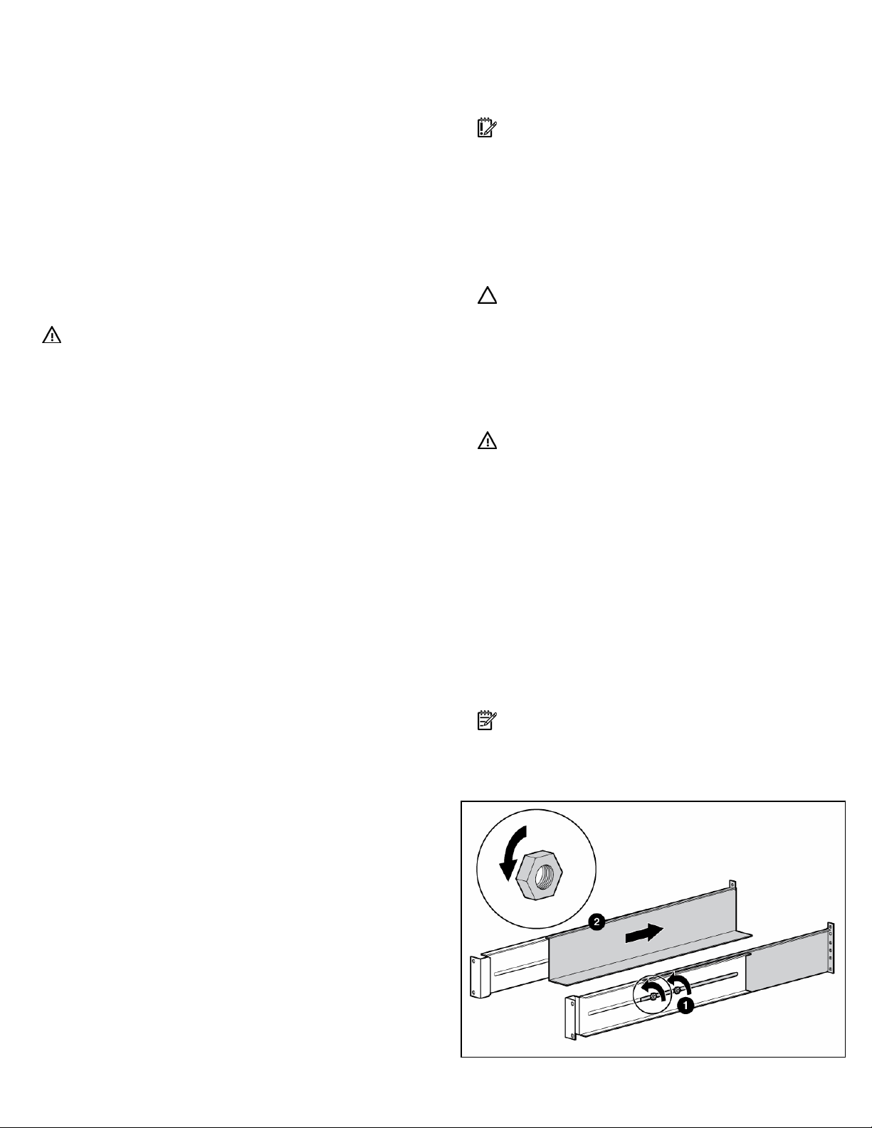
1. Loosen the hex nuts, and extend the brackets to the
desired length.
for any reason.
NOTE: Mounting hardware for square- and
round-holed racks is included in the UPS kit.
Page 3

2. Insert screws through the rack into the mounting rail and
the front of each mounting bracket.
5. Tighten the hex nuts.
3. Install cage nuts or clip nuts into the rear of the rack.
4. Insert screws through the mounting rail into the cage nuts
or clip nuts.
Preparing the rails for integrated shipping
If the unit is to be shipped in an HP 9000 or
10000 series rack:
1. Remove the hex nuts, flat washers, and lock washers
from the mounting rail.
2. Install the rail reinforcement plates and tighten using the
hex nuts with captive washers included in the kit, instead
of the nuts included with the rail.
3. Install the rear mounting brackets using hex nuts. Wait
until the unit is installed and the brackets are adjusted
before tightening the nuts.
Page 4

Powering down the UPS
1. Shut down all load devices.
2. Press the Standby button to take the UPS out of Operate
mode. Power to the load receptacles ceases.
3. Disconnect the UPS from utility power.
4. Wait at least 60 seconds for the UPS internal circuitry
to discharge.
Switching off the ERM circuit breaker
WARNING: To prevent personal injury from
electric shock or damage to the equipment,
verify that the circuit breaker is in the
Off position.
3. Install the mounting ears on the chassis using the
screws provided.
4. With one person on each side, lift the chassis to rail
level and slide the chassis on the mounting rails.
5. Attach the chassis to the rack using the supplied screws.
6. If using the rear mounting brackets, be sure that the
bracket tabs are fully inserted into the rear panel cutouts,
then tighten the brackets.
Installing the ERM
Before installing the ERM, review and observe all warnings in
"Precautions (on page 1)."
WARNING: Uneven mechanical loading in
the rack may cause a hazardous condition.
CAUTION: Always plan the rack installation so that
the heaviest item is on the bottom of the rack. Install
the heaviest item first, and continue to populate the
rack from the bottom to the top.
1. Install the mounting rails ("Installing the mounting rails"
on page 2).
2. With one person on each side of the carton, lift the
chassis and lower it to the floor in front of the rack.
Attaching the ERM front bezel
Page 5

Connecting the ERM to the UPS
NOTE: To install a second ERM, plug the cable from
the second ERM into the socket at the rear of the first
ERM. Up to two ERM units can be connected.
Switching on the ERM circuit breaker
Charging the ERM batteries
Connect the UPS to a grounded utility power outlet. When the
UPS is plugged in, it automatically enters Standby mode and
begins charging the ERM batteries. With the UPS in Standby
mode, allow the ERM batteries to charge for at least 24 hours
before putting the UPS into service.
CAUTION: To ensure maximum runtime, be sure to
configure the UPS for the number of installed ERMs
using the UPS front panel controls.
Configuring the UPS
After the ERMs are installed, place the UPS in Configure
mode, and use the UPS front panel controls and LED
indicators to configure the UPS for the number of attached
ERMs. Other UPS parameters that can also be configured
are the nominal utility voltage level and Site Wiring
Fault detection.
In Configure mode, the LED front panel display changes
function to enable modification of the UPS parameters. Each
LED is associated with a different parameter.
Available
settings
Nominal
Voltage
Setting
Wiring
Fault
Setting
ERM
Setting
Parameter
200/208
Nom
220 Nom
230 Nom
240 Nom
Wiring Fault
0 ERMs
1 ERM
2 ERMs
To change the UPS configuration parameters:
1. Place the UPS in Configure mode.
The LEDs associated with the currently configured
parameters illuminate. A flashing green cursor indicates
where you are in the configuration process as you scroll
through the available settings.
2. To change the nominal voltage, press the On button to
advance the cursor to the LED associated with the
appropriate nominal voltage parameter. The selected
voltage configuration LED flashes.
Associated
LED
General
Alarm
(red)
On
Battery
(red)
Battery
Fault (red)
Site
Wiring
Fault (red)
Utility
(green)
0% to
25% load
(green)
26% to
50% load
(green)
51% to
75% load
(green)
Explanation (when LED is
illuminated)
Nominal utility voltage
level is set to 200/208
VAC (factory default for
326529-D71)
Nominal utility voltage
level is set to 220 VAC
Nominal utility voltage
level is set to 230 VAC
(factory default for
326529-B31)
Nominal utility voltage
level is set to 240 VAC
Audible alarm sounds
when ground is missing or
line and neutral
connections are reversed
UPS is configured for no
attached ERMs (factory
default)
UPS is configured for 1
attached ERM
UPS is configured for 2
attached ERMs
Page 6

3. Press the Standby button to select the nominal voltage
configuration. The LED associated with the old input
voltage parameter turns off, and the LED associated with
the new input voltage parameter illuminates solid green.
NOTE: Only one nominal utility voltage can be
configured. When setting voltage configuration
parameters, selecting an On value for any one
parameter automatically sets the other possibilities
to Off.
4. To enable the Wiring Fault parameter, press the On
button to advance the cursor to the Utility LED, then press
the Standby button. The LED illuminates solid green.
This parameter is disabled by default, and should only
be enabled for line-to-neutral connections. Enabling this
feature for line-to-line power sources causes a
false alarm.
5. To configure the UPS for the number of connected ERMs,
press the On button to advance the cursor to the load
LED associated with the number of ERMs attached to
the UPS.
6. Press the Standby button to select the appropriate ERM
configuration. The associated LED illuminates
solid green.
7. To save the configuration settings and exit Configure
mode, press the Test/Alarm Reset button.
NOTE: Configure mode times out after 2 minutes. If
the Test/Alarm Reset button has not been pressed, any
new selections are not saved.
UPS front panel controls
UPS front panel LED indicators
The front panel is shown with the bezel removed.
Item LED description
1 Overload
2 76% to 100% load
3 51% to 75% load (2 ERMs)
4 26% to 50% load (1 ERM)
5 0% to 25% load (0 ERMs)
6 General Alarm
7 On Battery
8 Battery Fault
9 Site Wiring Fault
10 Utility
11 Configure Mode On
For more information, see "LED and audible alarm
troubleshooting" in the user guide.
The front panel is shown with the bezel removed.
Item Description Function
1 On button Powers up the UPS
2 Standby button Places the UPS in Standby mode
Test/Alarm Reset
3
button
• Silences UPS alarms
• Tests the LEDs
4 Configure button Places the UPS in Configure mode
Legal notice
© Copyright 2003, 2006 Hewlett-Packard Development Company, L.P.
The information contained herein is subject to change without notice. The only
warranties for HP products and services are set forth in the express warranty
statements accompanying such products and services. Nothing herein should
be construed as constituting an additional warranty. HP shall not be liable for
technical or editorial errors or omissions contained herein.
 Loading...