

Page 1

HP UPS R5000
person who installs and
voltage equipment and trained in recognizing hazards in products
User Guide
Abstract
This document includes installation, configuration, and operation information for the HP UPS R5000. This document is for the
maintains power products. HP assumes you are qualified in the servicing of highwith hazardous energy levels.
Part Number: 637909-003 A
February 2013
Ed
ition: 3
Page 2

© Copyright 2011, 2013 Hewlett-Packard Development Company, L.P.
The information contained herein is subject to change without notice. The only warranties for HP products and services are set forth in the express
warranty statements accompanying such products and services. Nothing herein should be construed as constituting an additional warranty. HP shall
not be liable for technical or editorial errors or omissions contained herein.
Microsoft®, Windows®, Windows Vista®, and Windows Server® are U.S. registered trademarks of Microsoft Corporation.
Page 3

Contents
Overview ..................................................................................................................................... 6
UPS R5000 overview ................................................................................................................................. 6
Important safety information ........................................................................................................................ 6
Component identification ............................................................................................................... 7
UPS front panel ......................................................................................................................................... 7
UPS front panel controls ............................................................................................................................. 8
UPS rear panel ......................................................................................................................................... 8
REPO port ...................................................................................................................................... 9
ERM rear panel ....................................................................................................................................... 10
Installation and configuration ....................................................................................................... 11
Precautions ............................................................................................................................................. 11
Preparing to install the hardware ............................................................................................................... 11
Tools and materials ........................................................................................................................ 11
Selecting a site .............................................................................................................................. 12
Readying the equipment ................................................................................................................. 12
Installing the mounting rails ...................................................................................................................... 12
Preparing the rails for integrated shipping .................................................................................................. 16
Installing the UPS .................................................................................................................................... 17
Connecting the battery leads ........................................................................................................... 17
Attaching the UPS front bezel .......................................................................................................... 18
Connecting the serial communications port ....................................................................................... 18
Connecting the USB communications port ......................................................................................... 21
Connecting the REPO port .............................................................................................................. 21
Connecting the ground bonding cable ............................................................................................. 23
Connecting the network cable ......................................................................................................... 23
Connecting the UPS to utility power ................................................................................................. 24
Connecting devices to the UPS ........................................................................................................ 24
Connecting the UPS cord retention clips ........................................................................................... 25
Charging the UPS batteries ............................................................................................................. 25
Starting power to the load .............................................................................................................. 25
Configuring the UPS Network Module ........................................................................................................ 25
Connecting the configuration cable .................................................................................................. 25
Launching a terminal emulation program .......................................................................................... 26
Configuring the UPS Network Module network settings ...................................................................... 26
Accessing the web interface ............................................................................................................ 27
Configuring the UPS Network Module settings................................................................................... 28
Installing the ERM .................................................................................................................................... 28
Attaching the ERM front bezel ......................................................................................................... 29
Connecting the ERM to the UPS ....................................................................................................... 30
Charging the ERM batteries ............................................................................................................ 30
UPS operations ........................................................................................................................... 31
Modes of operation ................................................................................................................................. 31
Standby mode .............................................................................................................................. 31
Operate mode .............................................................................................................................. 31
Contents 3
Page 4

Auto-Bypass mode ......................................................................................................................... 31
Configuring the UPS ................................................................................................................................ 32
Changing the language.................................................................................................................. 32
Changing display functions ............................................................................................................. 32
Verifying the REPO port connection ........................................................................................................... 33
Powering down the UPS ........................................................................................................................... 34
Power management .................................................................................................................... 35
Power Protector software .......................................................................................................................... 35
Maintenance .............................................................................................................................. 37
Removing the UPS front bezel ................................................................................................................... 37
Removing the ERM front bezel ................................................................................................................... 37
Replacing the UPS Network Module .......................................................................................................... 37
Replacing the batteries ............................................................................................................................. 38
Important battery safety information ................................................................................................. 38
Battery care and storage guidelines ................................................................................................. 39
UPS battery replacement procedure ................................................................................................. 39
Replacing the UPS ................................................................................................................................... 41
Replacing the ERM .................................................................................................................................. 43
Updating the UPS firmware ...................................................................................................................... 43
Troubleshooting .......................................................................................................................... 44
Alarm troubleshooting .............................................................................................................................. 44
Silencing an audible alarm ............................................................................................................. 46
Battery connection condition ..................................................................................................................... 46
Bypass is unavailable .............................................................................................................................. 46
General alarm condition .......................................................................................................................... 46
Input voltage is out of range ..................................................................................................................... 47
Insufficient warning of low batteries ........................................................................................................... 47
Internal UPS fault condition ....................................................................................................................... 47
Low battery shutdowns ............................................................................................................................. 47
Overload condition ................................................................................................................................. 48
REPO condition ....................................................................................................................................... 48
Site wiring condition ................................................................................................................................ 48
UPS does not provide the expected backup time ......................................................................................... 48
UPS does not start ................................................................................................................................... 48
UPS frequently switches between utility and battery power ............................................................................ 48
UPS is in Auto-Bypass mode...................................................................................................................... 49
UPS is on battery ..................................................................................................................................... 49
UPS is on bypass..................................................................................................................................... 49
Utility power condition ............................................................................................................................. 49
Specifications ............................................................................................................................. 50
UPS physical specifications ....................................................................................................................... 50
ERM physical specifications ...................................................................................................................... 50
UPS input specifications ........................................................................................................................... 50
UPS output specifications .......................................................................................................................... 50
Power protection specifications ....................................................................................................... 51
Voltage specifications .................................................................................................................... 51
Output tolerance specifications ........................................................................................................ 51
Output feature specifications ........................................................................................................... 51
Battery specifications ............................................................................................................................... 52
Average battery runtime ........................................................................................................................... 52
Minimum battery runtime .......................................................................................................................... 52
Contents 4
Page 5

Environmental specifications ..................................................................................................................... 53
REPO port specifications .......................................................................................................................... 53
Spares ....................................................................................................................................... 54
Ordering spares ...................................................................................................................................... 54
UPS spare parts list .................................................................................................................................. 54
Hardware options ................................................................................................................................... 54
Regulatory information ................................................................................................................ 55
Safety and regulatory compliance ............................................................................................................. 55
Turkey RoHS material content declaration ................................................................................................... 55
Ukraine RoHS material content declaration ................................................................................................. 55
Warranty information .............................................................................................................................. 55
Limited warranty ..................................................................................................................................... 55
$250,000 Computer Load Protection Guarantee ......................................................................................... 55
Pre-Failure Battery Warranty ..................................................................................................................... 56
Recommended duration of use .................................................................................................................. 56
Electrostatic discharge ................................................................................................................. 57
Preventing electrostatic discharge .............................................................................................................. 57
Grounding methods to prevent electrostatic discharge .................................................................................. 57
Support and other resources ........................................................................................................ 58
Before you contact HP .............................................................................................................................. 58
HP contact information ............................................................................................................................. 58
Acronyms and abbreviations ........................................................................................................ 59
Documentation feedback ............................................................................................................. 60
Index ......................................................................................................................................... 61
Contents 5
Page 6

Overview
UPS R5000 overview
The HP UPS R5000 features a 3U rackmount design and offers power protection for loads up to 5000
VA/4500 W. Features include:
• 3U UPS height, 3U ERM height
• ERM technology that uses advanced battery management to increase battery service life, optimize
recharge time, and provide a warning before the end of useful battery life
• Extended runtime with up to four ERMs per UPS
• Easily replaceable battery modules that simplify maintenance
• Emergency shutdown control through the REPO port
• HP UPS Network Module network connectivity with monitoring and control
• Firmware that is service upgradeable through the standard DB-9 communication port
• Backed by worldwide agency approvals
To benefit from the latest product enhancements, update to the latest versions of UPS firmware and software.
NOTE: To download the latest versions of UPS firmware and software, see the HP website
(http://www.hp.com/go/rackandpower).
Important safety information
WARNING: To reduce the risk of fire, only connect unit input to a circuit provided with branch
circuit overcurrent protection for 40 A rating in accordance with the National Electric Code,
ANSI/NFPA 70.
Disconnect the charging source prior to connecting or disconnecting battery terminals.
Determine if the battery is inadvertently grounded. If inadvertently grounded, remove the source
from the ground.
WARNING: Contact with any part of a grounded battery can result in electrical shock. Shock risk
is reduced if grounds are removed during installation and maintenance.
Overview 6
Page 7
Component identification
Control buttons
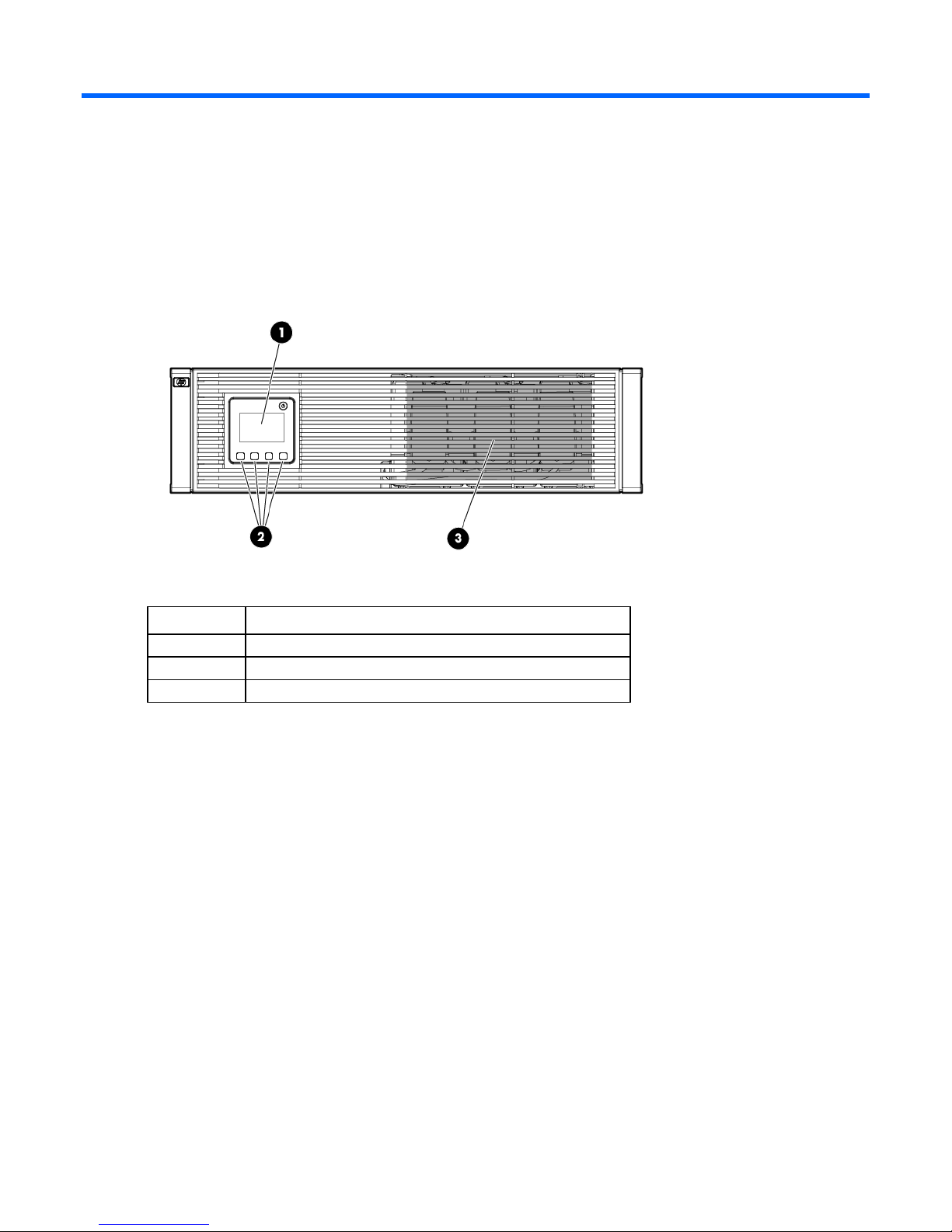
UPS front panel
Item Description
1
2
3
LCD display
Battery compartment
Component identification 7
Page 8
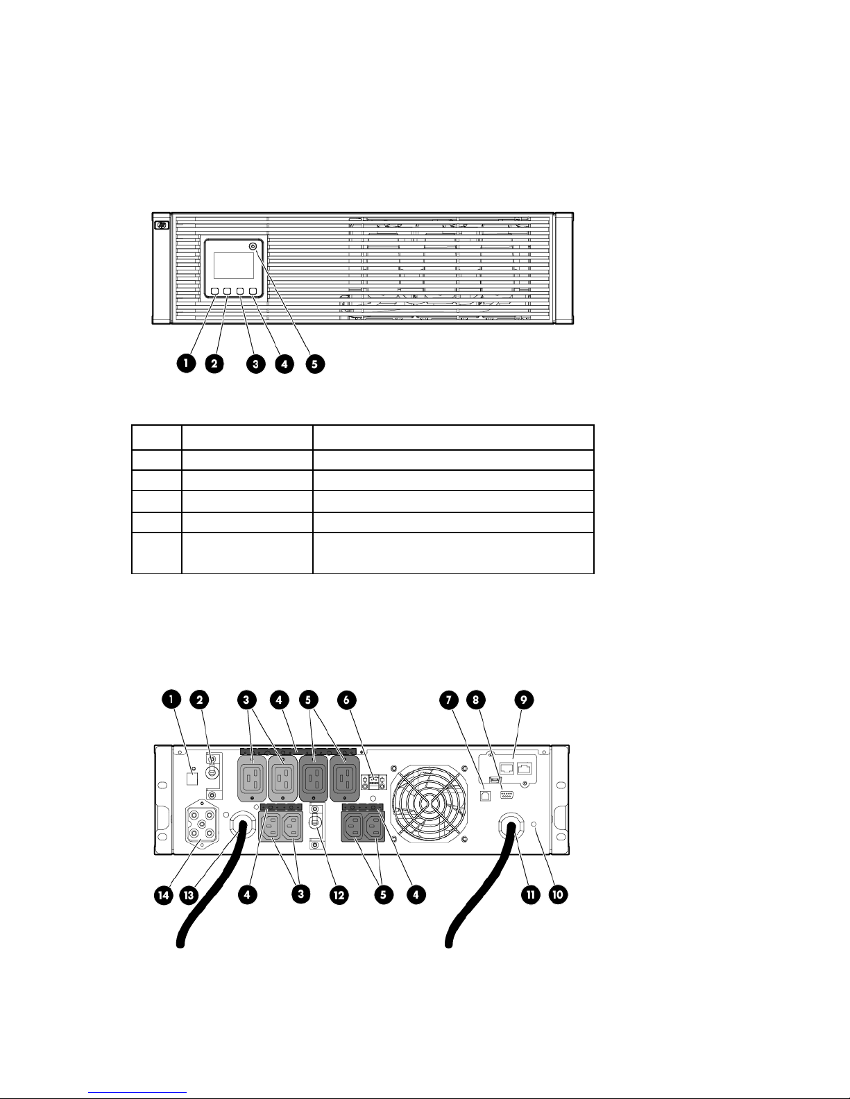
UPS front panel controls
•
•
Item Component Description
1
2
3
4
5
ESC button Cancel/return to the previous menu
Up arrow Scroll through the menu structure
Down arrow Scroll through the menu structure
Enter/select button Select an option
Power on/off button
UPS rear panel
Green—operating
Flashing green—on/off/standby
Component identification 8
Page 9

Item Description
1
2
3
ERM connector for the small plug on the split ERM cable
Load segment 1 circuit breaker (controls the C19 and C13
receptacles, but does not control the large output
receptacle)
Load segment 1 (two IEC-320-C19 receptacles and two
IEC-320-C13 receptacles)
4
5
6
7
8
9
10
11
12
13
14
REPO port
The UPS includes an isolated REPO port. When properly wired, the REPO feature enables the power at the
UPS output receptacles to be switched off from a remote location. To use this feature, the REPO port must be
connected to a remote, normally open switch (not supplied). The REPO switch is used in conjunction with a
main disconnect device that removes the AC source from the input of the UPS. When the switch is closed:
Cord retention clip attachment locations
Load segment 2 (two IEC-320-C19 receptacles and two
IEC-320-C13 receptacles)
REPO port
USB communications port
Serial communications port
HP UPS Network Module
Ground bonding screw
Input power line cord with NEMA L6-30 plug (NA/JPN) or
IEC-309-32A plug (INTL)
Load segment 2 circuit breaker
Large output NEMA L6-30R receptacle (NA/JPN) or
IEC-309-32A receptacle (INTL) associated with load
segment 1
ERM connector for the large plug on the split ERM cable
• The REPO feature immediately powers down protected devices and does not utilize the orderly
shutdown procedure initiated by power management software.
• The REPO feature shuts down UPS units operating under either utility or battery power.
NOTE: If the UPS was operating on battery power when the remote switch was closed, no power
is available to the load devices until utility power is restored and the UPS has been manually
To restore power to the load devices after the REPO feature is activated, press the On button after the AC
source is reconnected to the UPS.
To power down the entire network in the event of an emergency, the REPO ports of multiple UPS units can be
connected to a single switch.
powered up.
IMPORTANT: Pressing and holding the On button without utility present normally initiates a
battery start and the UPS assumes the load. However, if the On button is pressed and a REPO is
detected, battery start is inhibited and the UPS is not able to assume the load. The electronics
module fan spins and the General Alarm LED and an audible alarm are active as long as the On
button is held.
Component identification 9
Page 10
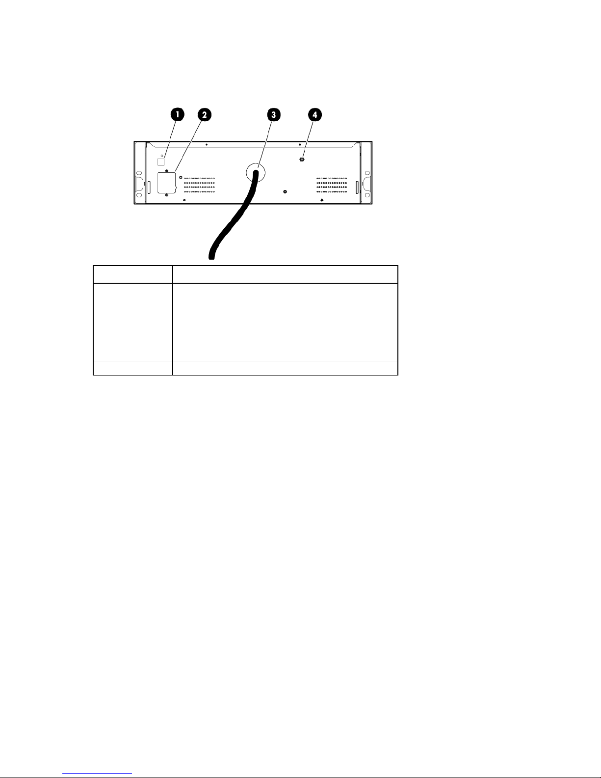
ERM rear panel
Item Description
1
2
3
4
ERM input connector for the small plug on the split ERM
cable of another ERM output
ERM input connector for the large plug on the split ERM
cable of another ERM output
Split ERM cable with two output connectors that attach to
the UPS or another ERM
Ground bonding screw
Component identification 10
Page 11
Installation and configuration
A risk of personal injury from electric shock and hazardous energy levels exists. The
Precautions
Save these instructions. This document contains important safety instructions that should be followed during
installation, operation, and maintenance of the UPS and batteries.
WARNING:
installation of options and routine maintenance and service of this product must be performed by
individuals who are knowledgeable about the procedures, precautions, and hazards associated
with AC power products.
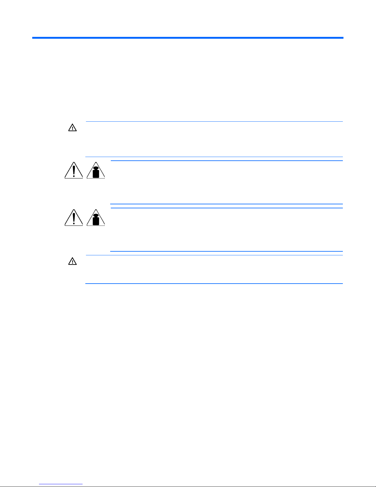
This symbol indicates that the UPS exceeds the recommended weight for one individual
57 kg
126 lb
to handle safely.
WARNING: To reduce the risk of personal injury or damage to the equipment, observe
local occupational health and safety requirements and guidelines for manual material
handling.
This symbol indicates that the ERM exceeds the recommended weight for one individual
63 kg
139 lb
to handle safely.
WARNING: To reduce the risk of personal injury or damage to the equipment, observe
local occupational health and safety requirements and guidelines for manual material
handling.
WARNING: To prevent personal injury from earth conductor leakage current:
• Do not operate the UPS while disconnected from the utility power source.
• Disconnect load devices before disconnecting the UPS from the utility power source.
Preparing to install the hardware
Before installing the hardware:
1. Be sure the necessary tools and materials (on page 11) are available.
2. Select an installation site.
Tools and materials
3. Prepare the equipment ("Readying the equipment" on page 12) for installation in the rack.
The following tools are required for installation:
• Phillips screwdriver
• 10-mm hex-nut driver
The following items are supplied with the rack:
• Screws
Installation and configuration 11
Page 12

• Hex nuts
• Cage nuts
• Cage nut-fitting tool
Selecting a site
WARNING: To prevent fire or electric shock, install the unit in a temperature- and
When selecting a site, consider the following factors:
• Elevated operating ambient temperature—If the equipment is installed in a closed or multi-unit rack
• Reduced air flow—In the rack, the rate of air flow required for safe operation of the equipment must not
• Circuit overloading—Consideration should be given to the connection of the equipment to the supply
• Reliable earthing—Reliable earthing of rack-mounted equipment should be maintained. Particular
humidity-controlled indoor environment, free of conductive contaminants.
assembly, the operating ambient temperature of the rack environment might be greater than room
ambient temperature. Install the equipment in an environment compatible with the operating
temperature ("Environmental specifications" on page 53).
be compromised.
circuit and the effect that overloading of the circuits might have on overcurrent protection and supply
wiring. Appropriate consideration of equipment nameplate ratings should be used when addressing
this concern.
attention should be given to supply connections other than direct connections to the branch circuit, such
as the use of power strips.
• Electrical requirements—All models require a dedicated (unshared) branch circuit, suitably rated for the
specific UPS as stated in "Input specifications ("UPS input specifications" on page 50)" .
Readying the equipment
1. Check the battery recharge date specified on the label that is affixed to the shipping carton.
IMPORTANT: Do not use the battery if the recharge date has passed. If the date on the battery
recharge date label has passed without the battery being recharged, contact an HP authorized
2. Transport the packaged unit to its installation location.
3. Unpack the equipment near the rack where the unit will be assembled.
service representative for directions.
CAUTION: Always plan the rack installation so that the heaviest item is on the bottom of the rack.
Install the heaviest item first, and continue to populate the rack from the bottom to the top.
Installing the mounting rails
Installation and configuration 12
Page 13
WARNING: To reduce the risk of personal injury or damage to the equipment, be sure that:
• The leveling feet are extended to the floor.
• The full weight of the rack rests on the leveling feet.
• The stabilizing feet are attached to the rack if it is a single-rack installation.
• The racks are coupled together in multiple-rack installations.
• Only one component is extended at a time. A rack may become unstable if more than one
component is extended for any reason.
NOTE: Mounting hardware for square- and round-holed racks is included in the UPS kit.
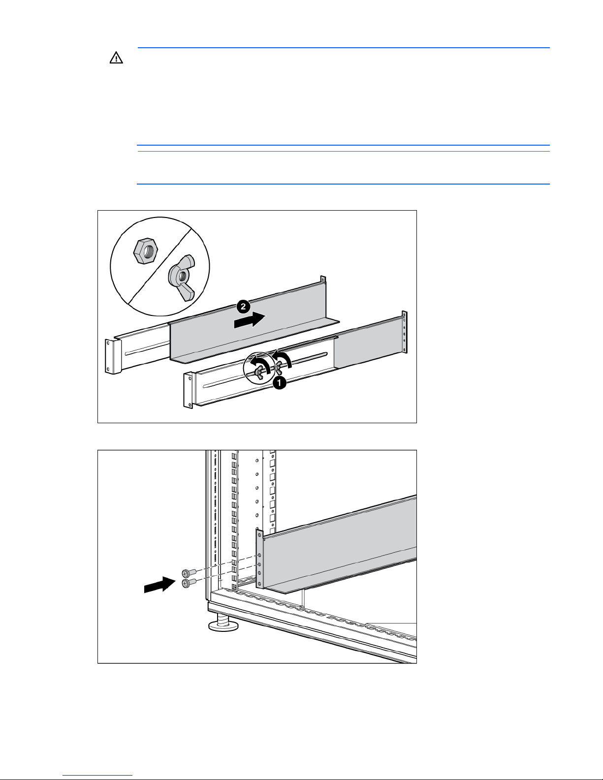
1. Loosen the wing nuts or hex nuts, and then extend the brackets to the appropriate length.
2. Insert screws through the rack into the mounting rail and the front of each mounting bracket.
Installation and configuration 13
Page 14
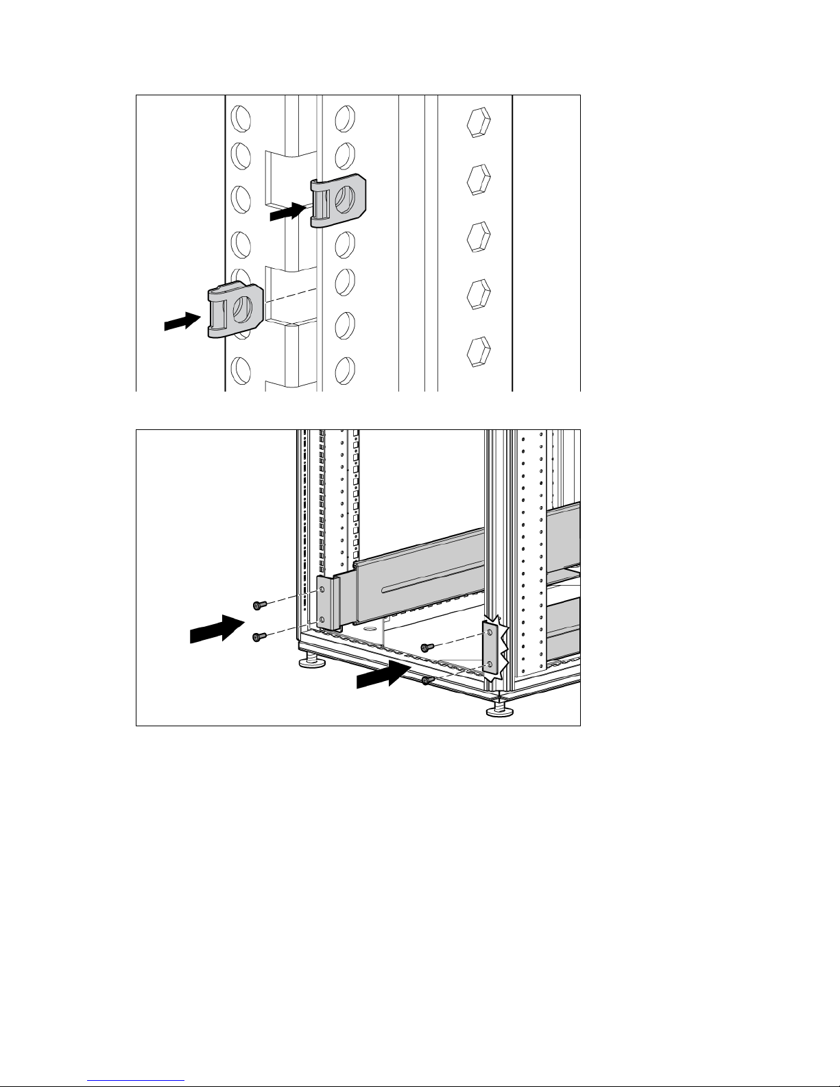
3. Install clip nuts into the rear of the rack.
4. Insert screws through the mounting rail into the clip nuts.
Installation and configuration 14
Page 15
5. Install the rail reinforcement plates and tighten using hex nuts with captive washers included in the kit,
instead of the nuts included with the rail.
6. Tighten the wing nuts or hex nuts.
Installation and configuration 15
Page 16
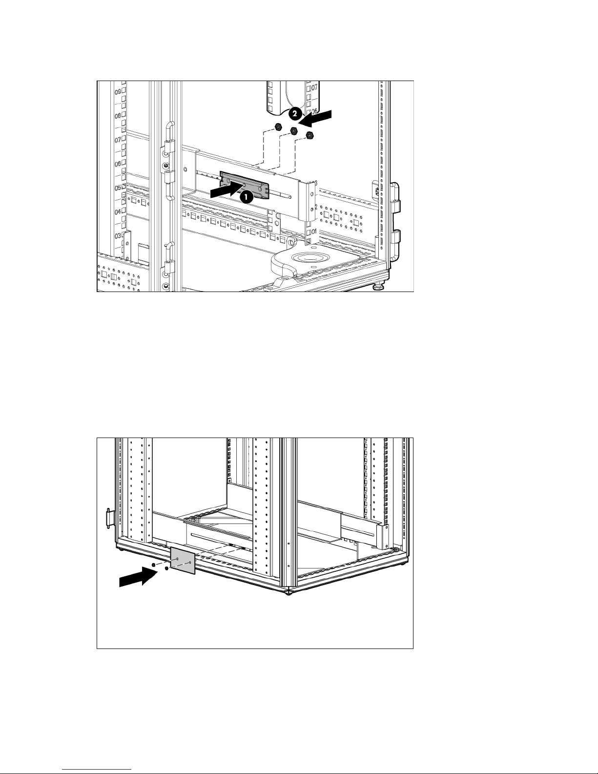
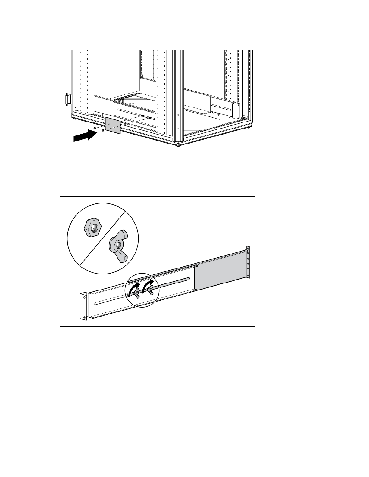
7. Install the rear mounting brackets using hex nuts. Wait until the unit is installed and the brackets are
adjusted before tightening the nuts.
Preparing the rails for integrated shipping
If the unit is to be shipped in an HP 9000 or 10000 series rack:
1. Remove the hex nuts, flat washers, and lock washers from the mounting rail.
2. Install the rail reinforcement plates and tighten using the hex nuts with captive washers included in the
kit, instead of the nuts included with the rail.
3. Install the rear mounting brackets using hex nuts. Wait until the unit is installed and the brackets are
adjusted before tightening the nuts.
Installation and configuration 16
Page 17
Installing the UPS
To prevent personal injury from electric shock or damage to the equipment, remove
Before installing the UPS, review and observe all warnings in "Precautions (on page 11)."
WARNING: A risk of personal injury or damage to the equipment exists. Uneven loading of
equipment in the rack might cause the rack to become unstable. Install the heavier components
1. Install the mounting rails ("Installing the mounting rails" on page 12).
2. With one person on each side of the carton, lift the chassis and lower it to the floor in front of the rack.
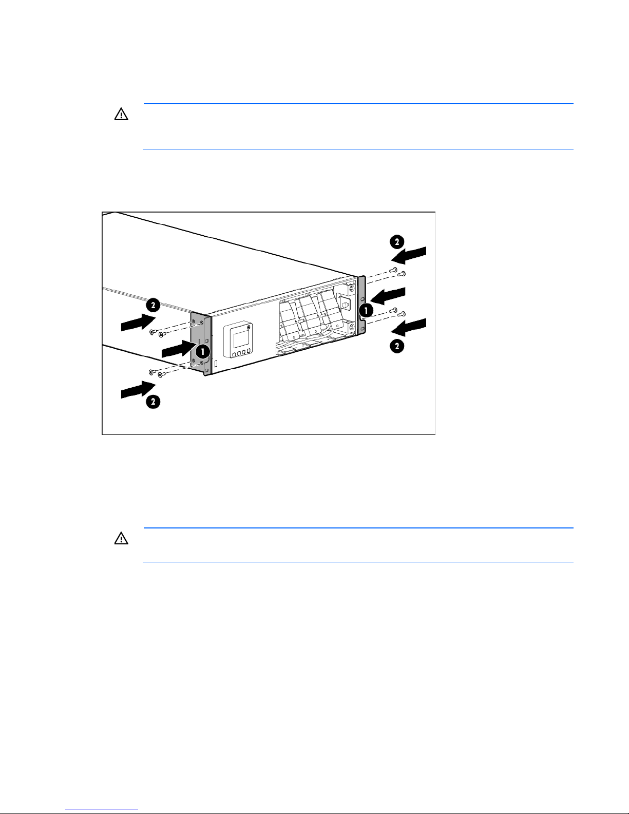
3. Install the mounting ears on the chassis using the screws provided.
first, and then continue to populate the rack from the bottom to the top.
4. With one person on each side, lift the chassis to rail level and slide the chassis on the mounting rails. Be
sure that the cleat brackets slide into the channels on the rear stabilization brackets.
5. Attach the chassis to the rack using the supplied screws.
Connecting the battery leads
WARNING:
the battery lead labels before connecting the battery leads.
Installation and configuration 17
Page 18
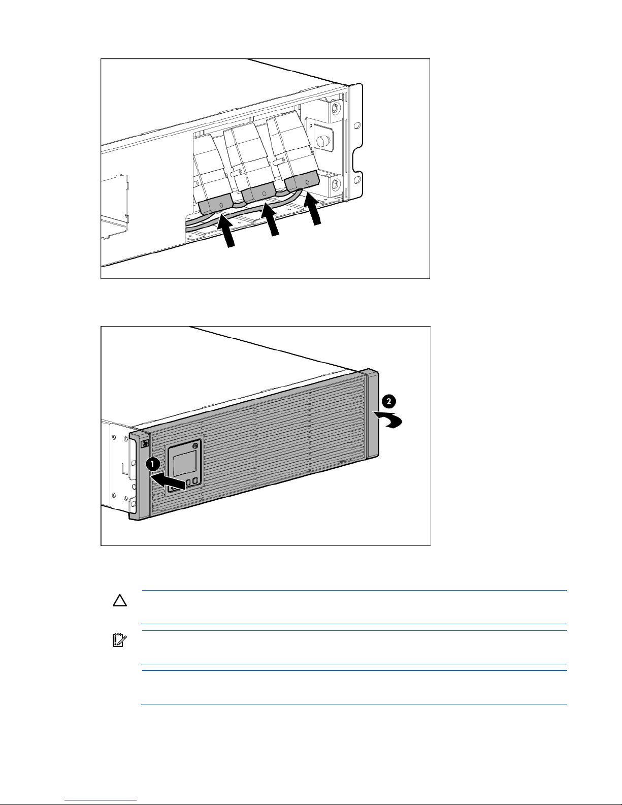
Attaching the UPS front bezel
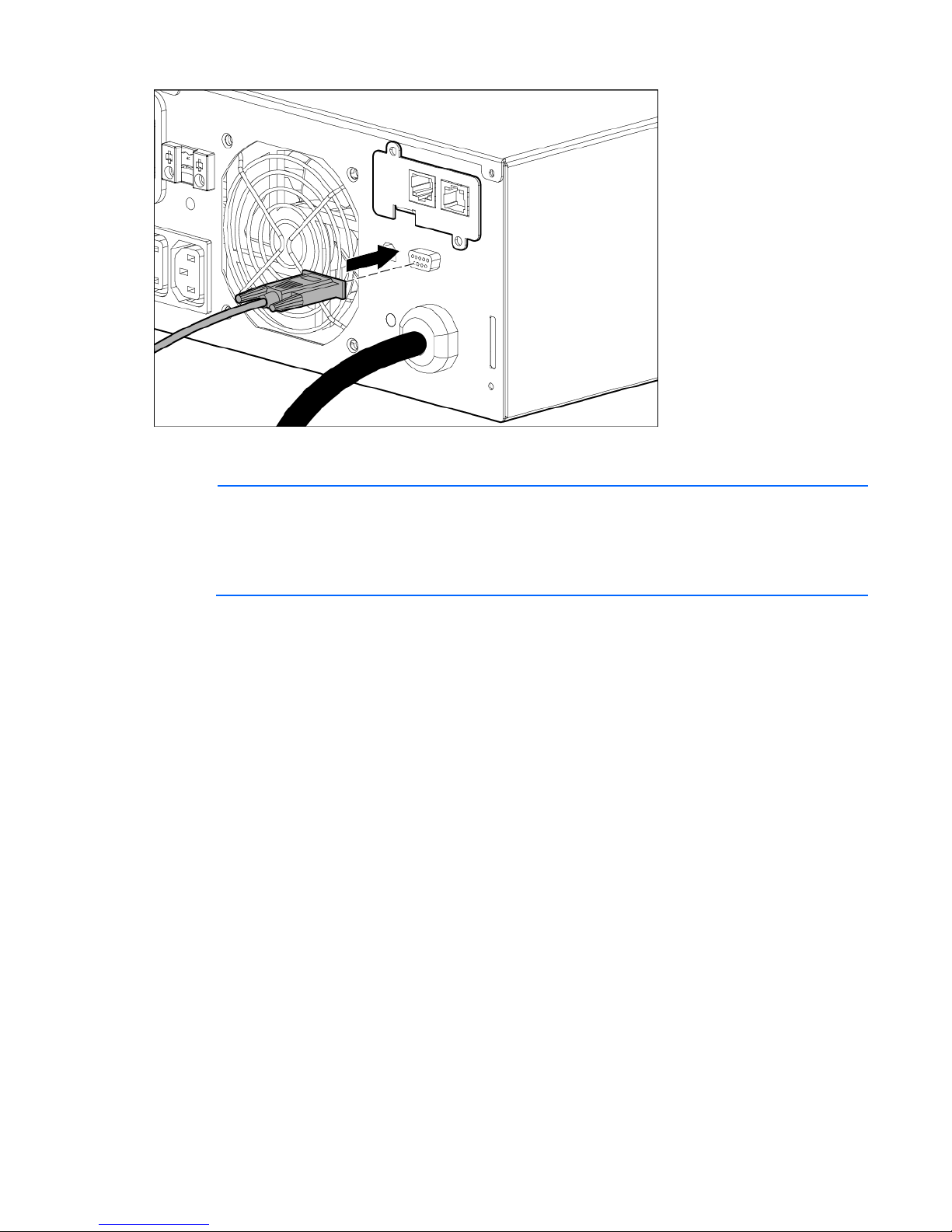
Connecting the serial communications port
CAUTION: Use only the computer interface cable supplied with the UPS to connect the
communications port to the host computer.
IMPORTANT: Power protector software requires the communications port to be appropriately
cabled to the host computer.
NOTE: This port is only used for firmware upgrades. For additional information, see "Updating
the UPS firmware (on page 43)."
Installation and configuration 18
Page 19
Configuring a USB to serial converter
NOTE: This procedure was tested on the Windows® XP Professional, Windows Server® 2003,
and Windows
®
Vista Enterprise operating systems using the HP USB to serial converter (part
number 304098-001). Depending on your system configuration, a driver download might be
required to successfully install the converter. The driver can be downloaded from the USB-Drivers
website (http://www.usb-drivers.com/drivers/123/123294.htm).
To configure a USB port to the COM 1 port on systems that do not have available serial ports:
1. Connect the USB to serial converter to the USB port on your system.
2. For Windows Vista, click Start, select Control Panel, double-click System and Maintenance, and then
skip to step 4.
-orFor Windows XP, click Start, select Control Panel, click Performance and Maintenance, and then click
System.
-orFor Windows Server, click Start, select Control Panel, and then double-click System.
3. Click the Hardware tab.
4. Click Device Manager. The Device Manager screen appears.
5. In the tree displayed in the left panel, click the Ports (COM & LPT) branch to expand.
6. Double-click the port that is assigned to your USB to serial converter device. This port is usually named
with the device manufacturer's name followed by one of the following:
o USB to Serial Bridge (COM 4)
o USB Serial port
o Communications Port (COM1)
The Port Properties screen appears.
7. Click the Port Settings tab. The Port Settings screen appears.
8. Click Restore Defaults. The following default settings appear:
Installation and configuration 19
Page 20

o Bits per second: 9600
o Data Bits: 8
o Parity: None
o Stop bits: 1
o Flow control: None
9. Click Advanced. The Advanced Settings screen appears.
10. From the COM Port Number drop down menu, select Com 1 for the USB port number, and then click
OK.
If COM 1 is being used by another USB port, the following message appears:
This COM name is being used by another device. Using duplicate names can lead
to inaccessible devices and changed settings. Do you want to continue?
If this message appears, click YES. It might be necessary to disable the program accessing COM 1.
a. Click OK.
b. For Windows Vista, skip to step 13.
11. For Windows Server, reduce the Receive Buffer and Transmit Buffer to the low setting by scrolling down
to select low (1).
12. Be sure that the Use FIFO buffers (requires 16550 compatible UART) checkbox is selected.
For Windows XP, the USB settings might be different. Choose the lowest, most dependable Receive and
Transmit buffers by using the list menus, radio buttons, or other selection methods.
13. Click OK to close the Advanced screen.
14. Click OK to close the Device Manager screen.
15. Run the firmware Flash batch file program. Follow the instructions provided with the program.
Reassigning the USB COM ports
To reassign a device from COM 1 to another port:
1. From the open Device Manager screen, locate the USB device that is assigned to COM 1.
2. Double-click the port name.
The Port Properties screen appears.
3. Click the Port Settings tab.
The Port Settings screen appears.
4. Click Advanced.
The Advanced Settings screen appears.
5. Select an available USB port number from the COM Port Number drop down menu.
6. Click OK to close the Advanced screen.
7. Click OK to close the Port Settings screen.
8. Verify that the Device Manager screen shows that the USB to serial converter is assigned to COM 1,
and that the other USB device is assigned to a different port.
If the Device Manager screen does not automatically refresh to show the change:
a. Click Action.
The Action Menu appears.
Installation and configuration 20
Page 21

b. Click Scan for hardware changes to refresh the screen and display the changes.
Connecting the USB communications port
NOTE: This port is only used for firmware upgrades. For additional information, see "Updating
the UPS firmware (on page 43)."
Connecting the REPO port
WARNING: The pins on the REPO port are polarity sensitive. Be sure to verify polarity while
connecting the REPO port.
WARNING: To meet the requirements stated in NEC (NFPA 70) Articles 645-10 and 645-11, a
UPS installed in a computer equipment room must be connected to a REPO circuit.
IMPORTANT: The remote switch must be in the Off (open) position to enable power to the output
receptacles.
Installation and configuration 21
Page 22

NOTE: Wire the connector block using stranded, nonshielded wire (AWG #22 - #18, or
equivalent).
Separate wire pairs are attached to a single, normally-open contact in a parallel connection. HP
recommends using different colors for the positive and negative wires.
If a connector becomes disconnected and is reconnected with reversed polarity, a REPO is initiated. To avoid
REPO port disconnect:
• Minimize wire strain while connecting the REPO port.
• Avoid allowing the wires to hang in the rear of the UPS.
• Use tie wraps and tie wrap blocks to secure the wires tightly to the rack and the rear of the UPS.
For more information about the REPO port, see "REPO port (on page 9)" .
For information about verifying the REPO connection, see "Verifying the REPO port connection (on page 33)"
.
Installation and configuration 22
Page 23

Connecting the ground bonding cable
The ground bonding screw is provided as an attachment point for conductors. Use a ground bonding cable
if the rack contains any conductors for the purpose of functional grounding or bonding of ungrounded metal
parts.
The ground bonding cable is not included.
Connecting the network cable
Connect a standard Ethernet cable between the network connector on the UPS Network Module and a
network jack.
This connection is used to access the UPS Network Module remotely through the web interface. The UPS
Network Module also uses the network connection to communicate to the configured HPPP Clients and to
facilitate SNMP-based monitoring.
Installation and configuration 23
Page 24

To configure the UPS Network Module, see "Configuring the UPS Network Module (on page 25)."
Connecting the UPS to utility power
WARNING: To prevent injury from electric shock or damage to the equipment:
• Plug the input line cord into a grounded (earthed) electrical outlet that is installed near the
equipment and is easily accessible.
• Do not disable the grounding plug on the input line cord. The grounding plug is an important
safety feature.
• Do not use extension cords.
Connect the UPS to a grounded utility power outlet. When the UPS is plugged in, it automatically enters
Standby mode and begins charging the batteries.
Connecting devices to the UPS
CAUTION: Do not plug laser printers into the UPS output receptacles. The instantaneous current
Before connecting devices:
• Verify that the UPS will not overload by checking that the ratings of the devices do not exceed the UPS
drawn by this type of printer can overload the UPS.
capacity.
• Evenly distribute connected devices to both circuit breakers. See "UPS output specifications (on page
50)" for the maximum current rating for each receptacle.
After verifying that the UPS will not overload:
1. Turn on the circuit breakers for load segments 1 and 2.
NOTE: The circuit breaker for load segment 1 protects the C19 and C13 outlets but not the large
2. Connect the device power cords to the appropriate output receptacles on the rear panel of the UPS.
To provide additional receptacles, plug a PDU or other device into the high current, large output receptacle.
The large output receptacle is part of load segment 1 and can be turned off and on using power management
software ("Power Protector software" on page 35).
output receptacle.
Installation and configuration 24
Page 25

Connecting the UPS cord retention clips
Charging the UPS batteries
With the UPS in Standby mode, allow the batteries to charge before putting the UPS into service.
IMPORTANT: Charge the batteries for at least 24 hours before supplying backup power to
devices. The batteries charge to:
• 80 percent of their capacity within 3 hours
• 100 percent of their capacity within 48 hours
Starting power to the load
Start power to the load by placing the UPS in Operate mode.
IMPORTANT: AC power must be available the first time the UPS is started.
Configuring the UPS Network Module
NOTE: For more information about the UPS Network Module, see the HP Infrastructure
Before configuring the UPS Network Module, be sure that the network cable is connected.
Management Pack software CD and documentation for complete details.
Connecting the configuration cable
1. Connect the DB-9 connector on the DB-9 to RJ-45 cable to a serial connector on the host computer.
Installation and configuration 25
Page 26

2. Connect the RJ-45 connector on the DB-9 to RJ-45 cable to the Settings/AUX connector on the UPS
Network Module.
This connection is used to access and configure the UPS Network Module network settings locally through a
terminal emulation program.
Launching a terminal emulation program
NOTE: HyperTerminal is the serial communication program provided with Microsoft®
Windows® and is used in this section as an example for setting up a terminal emulation session.
1. Be sure that the UPS is powered on.
2. On the host computer, click Start, and select Programs>Accessories>Communications>HyperTerminal.
3. Enter a description, select an icon for the connection, and then click OK. The Connect To window
4. Select the serial connector on the host computer to which the DB-9 to RJ-45 adapter is attached, and
5. Select the following parameter values, and then click OK.
If you are using another utility, the steps might be different.
The Connection Description window appears.
appears.
then click OK. The COM Properties window appears.
o Bits per second—9600
o Data bits—8
o Parity—None
o Stop bits—1
o Flow control—None
Configuring the UPS Network Module network settings
On the terminal emulation session screen running on the host computer:
1. Press any key. The initialization process completes, and then you are prompted to enter the password.
Installation and configuration 26
Page 27

At the prompt, enter admin. The HP UPS Network Module Configuration Menu appears.
You can configure the DHCP server to permanently assign the same IP address for each
2.
Use the HP UPS Network Module Configuration Menu to configure the minimum settings required to
access the UPS Network Module remotely.
IMPORTANT: The IP address assigned to the UPS Network Module must be fixed. If the IP
address changes:
• The HPPP Client loses communication with the UPS Network Module.
3. If your network is configured with a DHCP server, the network settings are automatically assigned. To
• You can lose track of the UPS Network Module URL.
view the settings:
a. On the Main menu, enter 2 to display the Network Configuration submenu.
b. Enter 1 to view the network settings.
c. Record the IP address.
d. Enter 0 to return to the Main menu.
e. Enter 0 to exit the Configuration Menu. The UPS Network Module is operational.
NOTE:
UPS Network Module using the MAC address of the card.
4. If your network is not configured with a DHCP server:
a. On the Main menu, enter 2 to display the Network Configuration submenu.
b. Enter 2 to modify the network settings.
c. Follow the on-screen instructions to enter the static IP parameters. A Done message appears when
the parameters are saved.
d. Enter 0 to return to the Main menu.
e. Enter 1 to reset the UPS Network Module, and then enter 2 to restart the UPS Network Module with
the new IP settings.
Accessing the web interface
CAUTION: It is highly recommended that browser access to the UPS Network Module is isolated
1. On a network computer, launch a supported browser. The browser window appears.
2. In the URL field, enter:
from outside access using a firewall or isolated network.
http://xxx.xxx.xxx.xxx
-or-
https://xxx.xxx.xxx.xxx
where xxx.xxx.xxx.xxx is the static IP address of the UPS Network Module. The login screen appears.
3. Enter the user name in the User Name field. The default user name is admin.
4. Enter the password in the Password field. The default password is admin.
Installation and configuration 27
Page 28

5. Click Sign In. The HP UPS Network Module web interface appears.
Configuring the UPS Network Module settings
Use the Settings screens of the HP UPS Network Module web interface to configure the UPS Network Module.
For more information, see the HP UPS Network Module User Guide on the HP website
(http://www.hp.com/support/HPNM_Manuals).
Installing the ERM
Before installing the ERM, review and observe all warnings in "Precautions (on page 11)."
WARNING: A risk of personal injury or damage to the equipment exists. Uneven loading of
equipment in the rack might cause the rack to become unstable. Install the heavier components
1. Install the mounting rails ("Installing the mounting rails" on page 12).
2. With one person on each side of the carton, lift the chassis and lower it to the floor in front of the rack.
first, and then continue to populate the rack from the bottom to the top.
Installation and configuration 28
Page 29

3. Install the mounting ears on the chassis using the screws provided.
4. With one person on each side, lift the chassis to rail level and slide the chassis on the mounting rails. Be
sure that the cleat brackets slide into the channels on the rear stabilization brackets.
5. Attach the chassis to the rack using the supplied screws.
Attaching the ERM front bezel
Installation and configuration 29
Page 30

Connecting the ERM to the UPS
Connect both ends of the split ERM cable to the ERM connectors on the UPS rear panel. To install additional
ERMs, connect both ends of the split ERM cable from the next ERM into the connectors on the rear panel of
the previous ERM. Up to four ERM units can be connected.
Charging the ERM batteries
Connect the UPS to a grounded utility power outlet. When the UPS is plugged in, it automatically enters
Standby mode and begins charging the ERM batteries. With the UPS in Standby mode, allow the ERM
batteries to charge for at least 24 hours before putting the UPS into service.
IMPORTANT: To verify the attached ERMs are recognized, confirm the number of installed ERMs
using the UPS front panel control via the UPS Status Menu.
Installation and configuration 30
Page 31

UPS operations
Modes of operation
The UPS has three modes of operation:
• Standby mode (on page 31)
• Operate mode (on page 31)
• Auto-Bypass mode (on page 31)
Standby mode
In Standby mode:
• No power is available at the UPS output receptacles.
• The UPS charges the batteries as necessary.
The UPS can be placed in Standby mode when the UPS is in Operate mode (on page 31).
To place the UPS in Standby mode, press and hold the Power button. Power to the load ceases.
IMPORTANT: While in Standby mode, the UPS maintains the charge on the batteries, but no
power is available at the output receptacles. The UPS remains in Standby mode until an alternate
For the location of buttons, see "UPS front panel controls (on page 8)."
mode is selected or until utility power is removed.
Operate mode
In Operate mode:
• Power is available at the UPS receptacles.
• The UPS charges the batteries as necessary.
The UPS can be placed in Operate mode if either of the following conditions apply:
• The UPS is powered on and in Standby mode (on page 31).
• The UPS is powered off and no utility power is available.
To place the UPS in Operate mode, press and hold the Power button.
For the location of buttons, see "UPS front panel controls (on page 8)."
Auto-Bypass mode
The UPS automatically enters Auto-Bypass mode when one of the following conditions occurs:
• Extended overload
UPS operations 31
Page 32

• Over temperature
• Output short
• Hardware failure
Transferring the UPS between modes
To transfer between Operate mode and Bypass mode:
1. Press the ESC button to activate the menu options.
2. Press the down arrow to scroll to the Control menu, and then press the Enter button.
3. Press the Enter button to select Go To Bypass Mode.
To transfer between Bypass mode and Operate mode:
1. Press the ESC button to activate the menu options.
2. Press the down arrow to scroll to the Control menu, and then press the Enter button.
3. Press the Enter button to select Go to normal mode.
Configuring the UPS
Changing the language
Use the UPS front panel controls to configure the UPS.
To change the language:
1. Press the ESC button to activate the menu options.
2. Press the down arrow button until the Setting menu appears on the LCD menu screen.
3. Press the Enter button.
4. Press the down arrow button until the Change Language menu appears on the LCD menu screen.
5. Press the Enter button.
6. Press and hold the Enter button to change the language on the UPS.
Changing display functions
The control panel automatically dims after a long period of inactivity. Press any button to restore the screen.
Press the ESC button to activate the menu options. Use the up and down arrow buttons to scroll through the
menu structure. Press the Enter/Select button to enter a submenu or to select an option. Press the ESC button
Menu map for display functions
to cancel or return to the previous menu.
Main menu Submenu Display information or menu function
UPS Status
—
— Load percentage graph, System Status,
Alarm status Displays active alarms
Estimated Battery Runtime, Battery Charge,
Output Voltage and Output Frequency
UPS operations 32
Page 33

Main menu Submenu Display information or menu function
Site wiring fault alarm
Enables or disables site wiring fault alarm. The
Automatic battery test
Enables or disables battery test. Default:
—
Event Log
Measurements
—
—
—
—
Control
Battery status Battery Charging/Floating/Resting, Charge
Level, ERM Number, and Runtime
— Displays events and alarms
Output Output watts and VA
Output Output amps and power factor
Output Output voltage and frequency
Input Input voltage and frequency
Battery Battery voltage and percent charge
Go to Bypass mode Transfers the UPS system to internal Bypass
mode
When this command is active, the option
changes to Go to Normal mode.
—
—
—
—
Settings
Battery Test Schedules a battery test
Reset error state Reset alarms
Load segments Turns load segments on or off
Restore factory settings Resets the UPS back to factory settings
Change language Changes language settings. The default is
English.
—
User Password Enables or disables password. Default: Disable.
If Enable is selected, the password is USER. The
password cannot be changed.
—
—
—
—
—
—
Set date and time Sets date and time
Control commands from serial
port
Enables or disables serial port control
commands. Default: Enabled
Output voltage Sets output voltage
Auto start delay Selects load segment and delay time in seconds
Automatic on battery shutdown Selects load segment and delay time in seconds
On battery notice delay Sets delay time in seconds
—
default is Disabled
—
Battery low alarm Sets battery low alarm. Default: 3 minutes.
—
Disabled
—
Identification
LCD contrast Change LCD contrast. Default: +0
— UPS Type / Part Number / Serial Number /
NMC Firmware / Comm Firmware / UPS
Firmware
Verifying the REPO port connection
NOTE: While testing, operate connected equipment in a safe test mode so the effects do not
After connecting the REPO port (on page 21):
disrupt critical operations.
UPS operations 33
Page 34

1. Initiate a REPO by closing the REPO contact.
CAUTION: If the polarity is reversed while connecting the REPO port, the UPS powers up
normally.
2. Verify proper connection of the REPO port:
a. Power up the UPS by pressing the Power button.
b. Disconnect the REPO port.
c. Reconnect the REPO port.
If the polarity is correct, the REPO connectors can be disconnected, and then reconnected, without
initiating a REPO.
d. Verify that the UPS remains in Operate mode (on page 31).
e. If a REPO is initiated, the polarity is reversed. Check and correct the connections.
Powering down the UPS
1. Shut down all load devices.
2. Switch the load segment circuit breakers the OFF position.
3. Press and hold the Power button for 3 seconds. Power is removed from the load segments and the
ON/OFF button blinks.
UPS operations 34
Page 35

Power management
Power Protector software
HP Power Protector software ensures maximum power reliability of computer systems through comprehensive
control of UPSs. The easy-to-use browser interface enables novice users to configure and manage power
protection settings. To download the latest version of HP Power Protector software, see the HP website
(http://www.hp.com/go/rackandpower).
NOTE: To install and configure the software, see the software user guide. The software user
HP Power Protector:
• Does not require complex management systems, which simplifies deployment, configuration, and
guide is available for download from the HP website (http://www.hp.com/go/rackandpower).
management of UPS-protected environments.
• Manages a graceful shutdown of attached devices during utility power failures.
• Prioritize the shutdown timing of attached computers.
• Customizes alert generation with modifiable dialog boxes, command execution, and email and
broadcast messages.
• Monitors the status of the UPS and reports alarms.
• Displays a power log for analysis.
• Manages independent UPS load segments to provide separate power control of attached load devices.
The HP UPS Network Module (P/N AF465A) is a Minislot with an easy-to-use browser interface, which gives
you comprehensive control of the UPS and enables you to monitor and effectively manage power
environments. The UPS Network Module supports either a single UPS configuration or a dual redundant UPS
configuration for no single-point-of-failure.
The UPS Network Module can be configured to send alert traps to HP Systems Insight Manager and other
SNMP management programs or used as a stand-alone management system. This flexibility enables you to
monitor and manage UPSs through the network. To facilitate day-by-day maintenance tasks, the embedded
management software provides detailed system logs.
The UPS Network Module provides remote management of a UPS by connecting the UPS directly to the
network. Configuration and management of the UPS from anywhere and at any time through a standard web
browser.
The UPS Network Module (Minislot) is ideal for:
• Small to enterprise-sized customers that will benefit from remotely managing their UPS.
• Adding protection via the redundant UPS configuration.
• Gracefully performing scheduled shut-downs of attached equipment.
• Notifying administrative personnel in the event of a power failure.
• Prioritizes the timing of attached load device shutdowns.
Power management 35
Page 36

• Delays reboot by load segment after a power outage to sequence the startup of system components.
Power management 36
Page 37

Maintenance
Removing the UPS front bezel
Removing the ERM front bezel
Replacing the UPS Network Module
This component is hot-swappable and can be replaced without powering down the UPS.
Maintenance 37
Page 38

1. (optional) To replace the component with the UPS powered down, refer to "Powering down the UPS (on
page 34)."
2. Disconnect all cables attached to the UPS Network Module connectors.
3. Remove the two screws securing the UPS Network Module and slide the module out.
To replace the component, reverse the removal procedure.
NOTE: Replacing the UPS Network Module might require power management software to be
restarted or reconfigured.
Replacing the batteries
To replace the batteries:
1. Read and observe the requirements in "Important battery safety information (on page 38)" and "Battery
care and storage guidelines (on page 39)."
Important battery safety information
2. Follow the instructions in "UPS battery replacement procedure (on page 39)."
WARNING: The unit contains sealed lead-acid battery modules. To prevent fire or chemical
burns:
• Do not attempt to recharge batteries after removal from the unit.
• Do not disassemble, crush, or puncture the batteries.
• Do not short the external contacts of the batteries.
• Do not immerse the batteries in water.
• Do not expose to temperatures higher than 60°C (140°F).
WARNING: To prevent personal injury from hazardous energy:
• Remove watches, rings, or other metal objects.
• Use tools with insulated handles.
• Do not place tools or metal parts on top of batteries.
Maintenance 38
Page 39

WARNING: To prevent personal injury, prepare the area and observe all materials-handling
procedures when transporting a battery module. Battery modules weigh 11.1 kg (24.47 lb).
NOTE: Replace all battery modules at the same time with the same type of batteries originally
installed in the UPS.
Battery care and storage guidelines
• Minimize the amount of time the UPS uses battery power by matching the UPS configuration with the
utility voltage. Refer to "Configuring the UPS (on page 32)."
• Keep the area around the UPS clean and dust-free. If the environment is very dusty, clean the outside of
the UPS regularly with a vacuum cleaner.
• Maintain the ambient temperature at 25°C (77°F).
• If storing a UPS for an extended period, recharge the batteries every 6 months:
CAUTION: Because of the short shelf life of the batteries, avoid storing a battery spare as a
backup. Do not maintain an inventory of spare batteries on site unless a procedure to keep these
batteries charged while in storage is implemented.
a. Connect the UPS to utility power.
b. Allow the UPS to remain in Standby mode.
c. Allow the UPS to charge the batteries for at least 24 hours.
d. Update the battery recharge date label.
UPS battery replacement procedure
The battery modules are hot-swappable and can be replaced without powering down the UPS.
IMPORTANT: The UPS continues to run while the batteries are replaced and shows the battery
To remove the component:
1. Remove the UPS front bezel ("Removing the UPS front bezel" on page 37).
disconnected alarm. This alarm clears automatically when the batteries are reconnected.
Maintenance 39
Page 40

2. Disconnect the battery leads.
3. Remove the UPS battery bracket.
4. Remove the UPS battery modules.
IMPORTANT: Do not pull the battery leads when removing or installing the batteries.
Maintenance 40
Page 41

To replace the component, reverse the removal procedure.
IMPORTANT: Charge the batteries for at least 24 hours before supplying backup power to
devices. The batteries charge to:
• 80 percent of their capacity within 3 hours
• 100 percent of their capacity within 48 hours
Replacing the UPS
To remove the UPS:
1. Power down all attached load devices.
2. Power down the UPS ("Powering down the UPS" on page 34).
3. Unplug the UPS power cord.
4. Disconnect all cabling.
5. Remove the UPS front bezel ("Removing the UPS front bezel" on page 37).
Maintenance 41
Page 42

6. Disconnect the battery leads.
7. Remove the UPS battery bracket.
Maintenance 42
Page 43

8. Remove the UPS battery modules.
9. Remove the screws securing the UPS to the rack.
10. Remove the UPS from the rack.
To replace the component, reverse the removal procedure.
Replacing the ERM
To remove the ERM:
1. Disconnect all cabling.
2. Remove the front bezel ("Removing the ERM front bezel" on page 37) on the ERM that is being
replaced.
3. Remove the screws securing the ERM to the rack.
4. Remove the ERM from the rack.
To replace the component, reverse the removal procedure.
Updating the UPS firmware
To update the UPS firmware, see the HP website (http://www.hp.com/go/rackandpower).
Maintenance 43
Page 44

Troubleshooting
Rectifier Input Over Current
The UPS has detected that rectifier input current limits
Alarm
Alarm troubleshooting
This UPS is designed for durable, automatic operation and also to alert you whenever potential operating
problems might occur. Usually the alarms shown on the control panel do not mean that the output power is
affected. Instead, they are preventive alarms intended to alert you of a possible condition.
The following table describes typical alarms and conditions. If an alarm appears with a service code, contact
HP technical support ("Support and other resources" on page 58, "HP contact information" on page 58).
To check the Event Log for a list of active alarms:
1. Press the ESC button on the front panel display to activate the menu options.
2. Press the down arrow button until the Event Log menu appears.
3. Press the Enter button to display the list of alarms and conditions.
Alarm number Alarm name Alarm description Alarm type
1
6
7
8
12
25
26
27
28
31
55
56
Inverter AC Under Voltage The UPS has detected abnormally low output voltage
Input AC Over Voltage The utility RMS voltage is greater than the maximum
Input AC Under Voltage The utility RMS voltage is less than the minimum valid
Input Under/Over
Frequency
Remote Emergency Power
Off
Output Overload Load levels are at, or have exceeded, the
Inverter Output Over Current The UPS has detected that inverter output current limits
DC Link Over Voltage Indicates the link or rail voltage UPS has exceeded its
Inverter Fault The UPS has detected a fault in the inverter circuit
Shutdown Imminent Indicates that the UPS entered a state where it might
Low Battery Warning Warning alarm indicating battery remain or battery
Alarm
levels.
Alarm
valid utility threshold.
Notice
utility threshold.
The utility frequency is out of usable frequency range. Notice
The external contacts in the rear of the UPS are
configured for REPO operation and they have been
activated.
configurable threshold limit for a Level 1 Overload
condition.
have been exceeded.
have been exceeded.
upper threshold limit.
while attempting recovery from bypass or Fault
modes.
stop operating abruptly without notice. An alarm is
issued when the BTR reaches 0 at the end of a battery
discharge cycle after all connected devices should
have shutdown gracefully already.
time remaining is lower than the battery low warning
level defined for the UPS.
Alarm
Notice
Alarm
Alarm
Alarm
Alarm
Alarm
Troubleshooting 44
Page 45

Alarm number Alarm name Alarm description Alarm type
59
Utility Not Present The utility level has fallen below the Utility Not Present
threshold.
68
Battery DC Over Voltage Battery voltage levels have exceeded the maximum
allowable limits.
94
To Bypass Command A request to transfer to Manual Bypass Mode
received from software.
95
From Bypass Command A request to transfer to Operate Mode is received
from software.
143
On Manual Bypass The UPS is manually commanded to switch to bypass
and will remain in bypass until commanded out of
bypass.
149
Service Battery A faulted battery string is detected, and the battery
charger has been disabled until it is replaced.
159
Output Overload Level 2 Load levels are greater than a level 2 Overload
condition and less than a level 3 Overload condition.
162
168
169
170
172
Output Overload Level 3 Load levels are greater than a level 3 threshold. Alarm
UPS On Battery The UPS is operating from batteries. Notice
UPS On Bypass The UPS is operating from bypass. Notice
UPS Off The UPS is in Standby mode or Fault mode. Event
UPS On Command Indicates a manually requested transition from
Standby to Operate. This event is not triggered for
auto restarts.
173
UPS Off Command A UPS OFF command was received from remote S/W
and causes the UPS to open up all output relays and
shed the load.
174
Battery Shutdown The UPS has shut down due to running on battery for
a long enough time to exhaust the battery capacity.
181
191
UPS Control Power ON The UPS is powered up. Event
Battery Test Failed A weak battery string is detected during the battery
test.
194
Site Wiring Problem The difference between ground and neutral voltage is
less than 30 V.
199
Battery Disconnected Battery voltage is lower than the batteries
disconnected level defined for this UPS. If ERMs are
attached, this alarm does not trigger unless the ERMs
are also disconnected, since they are paralleled with
the battery bus.
237
UPS System Normal The UPS has started or returned to its normal
operating mode of operation and no alarms are
active.
1600
ABM State Charging The status of ABM charge mode is constant current
charging.
1601
1602
1603
1999
ABM State Floating The status of ABM charge mode is floating. Event
ABM State Resting The status of ABM charge mode is resting. Event
ABM State OFF The status of ABM charge mode is OFF or disabled. Event
Clock set done The UPS real time clock setting has been adjusted. Event
Notice
Alarm
Event
Event
Notice
Alarm
Alarm
Event
Event
Alarm
Notice
Alarm
Alarm
Event
Event
Troubleshooting 45
Page 46

Silencing an audible alarm
To silence an alarm, press any button on the front panel display to silence the alarm. If the alarm status
changes, the alarm beeps again, overriding the previous alarm silencing.
IMPORTANT:
• Although the audible alarm silences, the condition that caused the alarm to sound may still
exist.
For information about audible alarm conditions, see "Alarm troubleshooting (on page 44)."
• If a utility power failure caused the alarm, the alarm silences after power is restored.
Battery connection condition
Possible cause:
• The UPS does not recognize the internal batteries.
• Two or more battery trays are disconnected.
Action:
1. Be sure that all the battery trays are fully seated and locked in place.
2. If the condition persists, contact an HP authorized service representative.
Bypass is unavailable
Possible cause: The UPS is receiving utility power that might be unstable or in brownout conditions. The UPS
continues to supply power to the connected equipment.
Action:
1. Verify the bypass utility.
2. Check for one of the following alarms:
o Bypass over or under voltage
o Bypass over or under frequency
o Bypass unavailable
General alarm condition
Action:
1. If power management software is being used, check the log files to obtain specific error information to
help identify the problem.
For more information about the causes of a general alarm condition, see the HP Power Manager user
guide available for download from the HP website (http://www.hp.com/go/rackandpower).
2. Check the batteries:
a. Allow the UPS batteries to charge for 48 hours.
b. If a Battery Fault occurs, replace the batteries.
3. Reduce the load:
Troubleshooting 46
Page 47

a. Power down the UPS ("Powering down the UPS" on page 34).
b. Remove one or more load devices to reduce the power requirements.
c. Wait at least 5 seconds and restart the UPS.
d. If the condition persists, verify that the load devices are not defective.
4. Allow the UPS to cool:
a. Power down the UPS ("Powering down the UPS" on page 34).
b. Clear vents and remove any heat sources.
c. Verify that the airflow around the UPS is not restricted.
5. Wait at least 5 minutes and restart the UPS.
6. If the condition persists, contact an HP authorized service representative.
Input voltage is out of range
Action:
1. Check the input voltage and reconfigure the UPS ("Configuring the UPS" on page 32).
2. Contact a qualified electrician to verify that the utility power is suitable for the UPS.
Insufficient warning of low batteries
Action:
1. Verify that the power management software is not delaying the shutdown of attached servers when the
UPS is in a low battery condition.
2. Allow the UPS batteries to charge for 48 hours.
3. If a Battery Fault occurs, replace the batteries.
Internal UPS fault condition
Action:
1. Power down the UPS ("Powering down the UPS" on page 34).
2. If the condition persists, contact an HP authorized service representative.
Low battery shutdowns
Possible cause::Ungraceful shutdown of attached servers occurs when the UPS is in a low battery condition.
Action:
1. Verify that the power management software is not delaying the shutdown of attached servers when the
UPS is in a low battery condition.
2. Allow the UPS batteries to charge for 48 hours.
3. If a Battery Fault occurs, replace the batteries.
Troubleshooting 47
Page 48

Overload condition
Possible cause: Power requirements exceed the UPS capacity. For output overload ranges, see "UPS output
specifications (on page 50)."
Action:
Remove one or more load devices to reduce the power requirements.The UPS continues to operate, but might
switch to Auto-Bypass mode (on page 31) if the load increases.
The alarm resets when the conditions becomes inactive.
REPO condition
Action:
• If the remote switch is closed, then open the switch to enable power to the output receptacles.
• If the condition occurred while reconnecting a disconnected REPO port, then verify the polarity of the
REPO connector pins.
For more information about REPO ports, see "Connecting the REPO port (on page 21)."
Site wiring condition
Action: Contact a qualified electrician to be sure that:
• The line and neutral wires are not reversed in the wall outlet.
• A ground wire connection does not exist.
UPS does not provide the expected backup time
Action:
1. Be sure that the battery circuit breakers are in the On position.
2. Allow the UPS batteries to charge for 48 hours.
3. If the condition persists, contact an HP authorized service representative.
UPS does not start
Action:
1. Be sure that the power cord is plugged in to a utility power receptacle.
2. Check the power source at the utility power receptacle.
UPS frequently switches between utility and battery
power
Action:
Troubleshooting 48
Page 49

1. Check the input voltage and reconfigure the UPS ("Configuring the UPS" on page 32).
2. Contact a qualified electrician to verify that the utility power is suitable for the UPS.
UPS is in Auto-Bypass mode
Action:
1. If power management software is being used, check the log files to obtain specific error information to
help identify the problem.
For more information about the causes of a general fault condition, see the HP Power Manager user
guide available for download from the HP website (http://www.hp.com/go/rackandpower).
2. Verify that no blockage of airflow to the front bezel and rear panel exists.
UPS is on battery
Action: Save files and shut down connected equipment.
UPS is on bypass
Possible Cause: The UPS is in Auto-Bypass mode (on page 31).
Action:
The equipment transferred to bypass utility power. Battery mode is not available and the equipment is not
protected; however, the utility power continues to be passively filtered by the UPS.
Check for one of the following alarms:
• Overload
• Over temperature
• Output short
• Hardware failure
Utility power condition
The utility input voltage is outside the operating range.
Action:
1. Check the input voltage and reconfigure the UPS ("Configuring the UPS" on page 32).
2. Contact a qualified electrician to verify that the utility power is suitable for the UPS.
Troubleshooting 49
Page 50

Specifications
74.4 cm (29.3 in)
1 x L6-30R
Up to full UPS power rating
UPS physical specifications
Parameter Value
Height
Depth
Width
Weight
12.7 cm (5 in)
43.7 cm (17.2 in)
57 kg (126 lb)
ERM physical specifications
Parameter Value
Height
Depth
Width
Weight
12.7 cm (5 in)
71.9 cm (28.3 in)
43.8 cm (17.24 in)
63 kg (139 lb)
UPS input specifications
NOTE: An asterisk (*) indicates the default setting.
UPS model Utility voltage
frequency (Hz)
R5000 NA/JPN
R5000 INTL
50/60 200/208*/220/230/
50/60 200/208/220/230*/
Available settings
utility voltage (VAC)
240
240
UPS output specifications
UPS model Load
segment
R5000 NA/JPN
1 20 A¹ 2 x IEC-320-C19 16 A per receptacle²
Circuit
breaker
Dedicated
Line cord
branch circuit
rating (A)
30 Nondetachable power
cord with NEMA L6-30
plug
32 Nondetachable power
cord with 32 A IEC-309
plug
Output receptacles Maximum current
2 x IEC-320-C13 10 A per receptacle
Specifications 50
Page 51

2
20 A¹
2 x IEC-320-C19
16 A per receptacle²
1 x IEC-309-32A
Up to full UPS power rating
UPS model Load
segment
Circuit
breaker
R5000 INTL
1 20 A¹ 2 x IEC-320-C19 16 A per receptacle²
2 20 A¹ 2 x IEC-320-C19 16 A per receptacle²
1
The circuit breakers protect the C19 and C13 outlets.
2
If an extension bar is connected to a C19 receptacle, the maximum current for each C13 receptacle on the extension
bar is 10 A. The total maximum current for the extension bar is 12 A.
Power protection specifications
UPS model VA Nominal power
rating (W)
R5000 NA/JPN
R5000 INTL
5000 4500 200/208, 220,
5000 4500 200/208, 220,
Output receptacles Maximum current
2 x IEC-320-C13 10 A per receptacle
2 x IEC-320-C13 10 A per receptacle
2 x IEC-320-C13 10 A per receptacle
Nominal voltage
setting
230, 240
230, 240
Voltage specifications
Configuration setting (VAC) Available nominal output voltage
(VAC)
200/208
220
230
240
204
220
230
240
Output tolerance specifications
Source of power Regulation
Utility power (nominal
range)
Battery power
-10% to +6% of nominal output voltage rating
(within the guidelines of the Computer Business
Equipment Manufacturers Association)
±5% of nominal output voltage rating
Output feature specifications
Feature Specification
Online efficiency
Voltage wave shape
94% nominal input voltage
Sine wave; 5% THD with typical PFC load
Specifications 51
Page 52

16
44
145
36
100
360
Feature Specification
Surge suppression
Noise filtering
High-energy 6500 A peak
MOVs and line filter for normal and common mode
use
Battery specifications
Feature Specification
Type
Voltage
Charging
Each model contains maintenance-free, sealed, valve
regulated lead-acid batteries with an 8-year minimum float
service life at 25°C (77°F).
The battery modules have a battery string voltage of 216 V.
Complete charge takes no more than 48 hours.
Approximately 3 hours to 80 percent capacity at default
nominal utility voltage and no load.
Average battery runtime
Average battery runtimes are approximate and vary depending on connected equipment, configuration,
battery age, temperature, and so on. These estimates are based on the batteries at beginning of life.
Load % Estimated
battery runtime
(minutes)
20
50
80
100
* NA/JPN model only
44 123 436
7 25 83
5.7 20 64
Runtime with
one ERM
(minutes)
Runtime with
four ERMs
(minutes)*
Minimum battery runtime
Minimum battery runtimes are at beginning of life.
Load % Internal battery
runtime
(minutes)
20
50
80
100
* NA/JPN model only
12 36 115
6 23 80
5 18 58
Runtime with
one ERM
(minutes)
Runtime with
four ERMs
(minutes)*
Specifications 52
Page 53

Environmental specifications
Feature Specification
Operating temperature
Nonoperating
temperature
Relative humidity
Operating altitude
Nonoperating altitude
Audible noise
10°C to 40°C (50°F to 104°F); UL-tested at 25°C
(77°F)
-25°C to 55°C (-13°F to 131°F)
20% to 80%; noncondensing
Up to 2,000 m (6,600 ft) above sea level
15,000 m (49,212 ft) above sea level
Less than 45 dBA, normal operation
Less than 50 dBA, on battery power
REPO port specifications
The REPO port meets the requirements of NFPA Articles 645-10 and 645-11 for a Disconnecting Means.
Specifications 53
Page 54

Spares
Ordering spares
To order a spare, visit the HP website (http://www.hp.com/buy/parts).
To replace parts under warranty, contact an HP authorized service representative.
UPS spare parts list
Item Description Spare part
1
2
3
4
5
6
7
8
UPS unit NA/JPN 638826-001
UPS unit INTL 638827-002
UPS Network Module 636934-001
UPS battery module 638829-001
ERM unit 638828-001
UPS/ERM mounting hardware 638830-001
Mounting rail 419181-001
Computer interface cable 201092-001
Hardware options
For information on the supported hardware options, see the HP website
(http://www.hp.com/go/rackandpower).
number
Spares 54
Page 55

Regulatory information
Safety and regulatory compliance
For safety, environmental, and regulatory information, see Safety and Compliance Information for Server,
Storage, Power, Networking, and Rack Products, available at the HP website
(http://www.hp.com/support/Safety-Compliance-EnterpriseProducts).
BSMI notice
警語: 本產品是在第2 類環境中供商業和工業使用,為避免擾動
產生,可能需要一些安裝限制或額外的措施。
輸出的電纜長度,網路 LAN 纜線長度,接線使用上,
由專業人員安裝,長度不會超過 10 米。
Turkey RoHS material content declaration
Ukraine RoHS material content declaration
Warranty information
HP ProLiant and X86 Servers and Options (http://www.hp.com/support/ProLiantServers-Warranties)
HP Enterprise Servers (http://www.hp.com/support/EnterpriseServers-Warranties)
HP Storage Products (http://www.hp.com/support/Storage-Warranties)
HP Networking Products (http://www.hp.com/support/Networking-Warranties)
Regulatory information 55
Page 56

Limited warranty
IMPORTANT: The $250,000 Computer Load Protection Guarantee is offered only in The United
States and Canada.
To back up the wide range of features offered with the UPS, a 3-year limited warranty is provided.
$250,000 Computer Load Protection Guarantee
In addition to the limited warranty, a $250,000 Computer Load Protection Guarantee (provided by the
original equipment manufacturer) is offered.
The $250,000 Computer Load Protection Guarantee only applies if:
The UPS is plugged into a suitably grounded and wired outlet using no extension cords, adapters, other
ground wires, or other electrical connections.
The UPS installation complies with all applicable electrical and safety codes specified by the NEC.
The UPS is used under normal operating conditions and users comply with all instructions and labels.
The UPS is not damaged by accident (other than a utility power transient), misuse, or abuse.
o The Guarantee applies only to the original end-user and is non-transferable.
o The Guarantee does not include reimbursement for or restoration of any data loss.
The UPS is either connected directly to an enterprise class PDU, which is then connected directly to a
server, workstation, or personal computer, or the UPS is connected directly to a server, workstation, or
personal computer.
Pre-Failure Battery Warranty
The Pre-Failure Battery Warranty, standard on all UPS units, extends the advantage of a 3-year limited
warranty by applying it to the battery before it actually fails. The Pre-Failure Battery Warranty ensures that the
battery is replaced free of charge when a notification that the battery might fail is received from power
protector software. The battery warranty coverage is 3 years for parts. The warranty for the first year of
ownership includes parts and labor. If battery spares are not available for a particular UPS model, the entire
UPS, including its battery, is replaced.
A Pre-Failure Battery warning is given 30 days before a battery failure. The warning is given in one or both
of the following ways:
The display showing the battery is low.
Notification from the power protector software.
Recommended duration of use
Although tests and a multitude of customer experiences have shown no noticeable performance issues with
UPSs for significant time periods after expiration of the 3-year limited warranty, HP strongly recommends
replacing UPSs after a maximum of 5 to 6 years of use to assure full functionality and a safe operating
environment. This recommendation does not extend or in any way alter the warranty for UPSs which is limited
to a time period of 3 years and a coverage as stated in the applicable warranty statement.
Regulatory information 56
Page 57

Electrostatic discharge
Preventing electrostatic discharge
To prevent damaging the system, be aware of the precautions you need to follow when setting up the system
or handling parts. A discharge of static electricity from a finger or other conductor may damage system
boards or other static-sensitive devices. This type of damage may reduce the life expectancy of the device.
To prevent electrostatic damage:
• Avoid hand contact by transporting and storing products in static-safe containers.
• Keep electrostatic-sensitive parts in their containers until they arrive at static-free workstations.
• Place parts on a grounded surface before removing them from their containers.
• Avoid touching pins, leads, or circuitry.
• Always be properly grounded when touching a static-sensitive component or assembly.
Grounding methods to prevent electrostatic discharge
Several methods are used for grounding. Use one or more of the following methods when handling or
installing electrostatic-sensitive parts:
• Use a wrist strap connected by a ground cord to a grounded workstation or computer chassis. Wrist
straps are flexible straps with a minimum of 1 megohm ±10 percent resistance in the ground cords. To
provide proper ground, wear the strap snug against the skin.
• Use heel straps, toe straps, or boot straps at standing workstations. Wear the straps on both feet when
standing on conductive floors or dissipating floor mats.
• Use conductive field service tools.
• Use a portable field service kit with a folding static-dissipating work mat.
If you do not have any of the suggested equipment for proper grounding, have an authorized reseller install
the part.
For more information on static electricity or assistance with product installation, contact an authorized
reseller.
Electrostatic discharge 57
Page 58

Support and other resources
Before you contact HP
Be sure to have the following information available before you call HP:
• Active Health System log (HP ProLiant Gen8 or later products)
Download and have available an Active Health System log for 3 days before the failure was detected.
For more information, see the HP iLO 4 User Guide or HP Intelligent Provisioning User Guide on the HP
website (http://www.hp.com/go/ilo/docs).
• Onboard Administrator SHOW ALL report (for HP BladeSystem products only)
For more information on obtaining the Onboard Administrator SHOW ALL report, see the HP website
(http://h20000.www2.hp.com/bizsupport/TechSupport/Document.jsp?lang=en&cc=us&objectID=c
02843807).
• Technical support registration number (if applicable)
• Product serial number
• Product model name and number
• Product identification number
• Applicable error messages
• Add-on boards or hardware
• Third-party hardware or software
• Operating system type and revision level
HP contact information
For United States and worldwide contact information, see the Contact HP website
(http://www.hp.com/go/assistance).
In the United States:
• To contact HP by phone, call 1-800-334-5144. For continuous quality improvement, calls may be
recorded or monitored.
• If you have purchased a Care Pack (service upgrade), see the Support & Drivers website
(http://www8.hp.com/us/en/support-drivers.html). If the problem cannot be resolved at the website,
call 1-800-633-3600. For more information about Care Packs, see the HP website
(http://pro-aq-sama.houston.hp.com/services/cache/10950-0-0-225-121.html).
Support and other resources 58
Page 59

Acronyms and abbreviations
ERM
extended runtime module
IEC
International Electrotechnical Commission
PDU
power distribution unit
PFC
power factor corrected
REPO
remote emergency power off
RMS
root-mean-square
UPS
uninterruptible power system
Acronyms and abbreviations 59
Page 60

Documentation feedback
HP is committed to providing documentation that meets your needs. To help us improve the documentation,
send any errors, suggestions, or comments to Documentation Feedback (mailto:docsfeedback@hp.com).
Include the document title and part number, version number, or the URL when submitting your feedback.
Documentation feedback 60
Page 61

Index
A
authorized reseller 58
B
backup time, insufficient 48
batteries, care and storage 39
batteries, charging 25
batteries, replacing 38, 39
battery replacement notice 55
battery warranty 55
bezel, removing 37
BSMI notice 55
buttons 7, 8
European Union notice 55
F
Federal Communications Commission (FCC)
notice 55
firmware, updating 43
frequent switching between battery and utility
power 48
front panel buttons 8
front panel components 7
G
ground bonding cable, connecting 23
grounding methods 57
C
Canadian notice 55
charging batteries 25
circuit breakers, location 8, 10
circuit breakers, switching on 24
components, identification 7, 8, 10
configuration of system 32
connecting devices to UPS 24
connectors 7, 8, 10
contacting HP 58
cord retention clip locations 8
cord retention clips, connecting 25
D
Declaration of Conformity 55
devices, connecting 24
disposal, battery 55
E
electrostatic discharge 57
environmental specifications 53
ERM, configuring 32
ERM, connecting 30
ERM, identifying components 10
ERM, installing 28
ERM, replacing 43
H
hardware options 54
hardware, preparing to install 11
high-current output receptacle, connecting 24
high-current output receptacle, location 8
HP technical support 58
I
input voltage is out of range 47
installing the ERM 28
insufficient backup time 48
internal UPS fault condition 47
J
Japanese notice 55
L
LCD panel 7
LEDs, troubleshooting 44
limited warranty 55
load protection guarantee 55
load segments, location 8
M
maintenance 37
Index 61
Page 62

modifications, FCC notice 55
N
nominal voltage, configuring 32
O
operations, UPS 31
optional items 54
ordering spares 54
output feature specifications 51
output tolerance specifications 51
overload condition 48
overview, REPO port 9
overview, UPS 6
P
phone numbers 58
power management 35
power protection specifications 50
preparation procedures 11
problem diagnosis 44
R
support 58
supported hardware 54
system configuration settings 32
T
Taiwan battery recycling notice 55
technical support 58
telephone numbers 58
temperature ranges (environmental) 53
tools 11
troubleshooting 44
U
unpacking the components 12
updating the firmware 43
UPS does not start 48
UPS firmware, updating 43
UPS is on battery 49
UPS Network Module 6, 25, 28
UPS operations 31
UPS, replacing 41
utility power condition 49
utility power, connecting 24
rear panel connectors 8, 10
receptacles, illustrated 8
regulatory compliance identification numbers 55
regulatory compliance notices 55
replacing the batteries 38, 39
replacing the ERM 43
replacing the UPS 41
REPO condition 48
REPO port, connecting 21
REPO port, location 8
REPO port, overview 9
REPO port, specifications 53
required information 58
required tools 11
S
safety considerations 11, 55
series number 55
shipping the UPS 16
site wiring condition 48
spare part numbers 54
spares 54
specifications 50
static electricity 57
storing batteries 39
V
voltage specifications 51
Index 62
 Loading...