

Page 1

Fax
Fax
Fax
Fax
HP LaserJet MFP
Analog Fax Accessory 300
Page 2

Page 3

HP LaserJet MFP
Analog Fax Accessory 300
English
Fax Guide
Page 4

Copyright Information
© 2004 Copyright
Hewlett-Packard Development
Company, L.P.
Reproduction, adaptation or
translation without prior written
permission is prohibited, except
as allowed under the copyright
laws.
The information herein is
subject to change without
notice.
The only warranties for HP
products and services are set
forth in the express warranty
statements accompanying such
products and services. Nothing
herein should be construed as
constituting an additional
warranty. HP shall not be liable
for technical or editorial errors or
omissions contained herein.
Part number: Q3701-90903
Edition 1, 9/2004
Safety Information
WARNING!
Potential Shock Hazard
Always follow basic safety
precautions when using this
product to reduce risk of injury
from fire or electric shock.
1 Read and understand all
instructions in this manual.
2 Observe all warnings and
instructions marked on the
product.
3 Do not touch the contacts
on the end of the
telephone cord or any of
the sockets on the fax
accessory product.
Replace damaged cords
immediately.
4 The phone cord is
electrified and can cause a
shock. When servicing the
product, be sure to
disconnect the phone cord
from the wall connector.
5 Never install telephone
wiring during a lightning
storm.
6 Unplug this product from
wall outlets and telephone
jacks before cleaning.
7 Do not install or use this
product near water or
when you are wet.
8 Install the product securely
on a stable surface.
9 Install the product in a
protected location where
no one can step on or trip
over the telephone line and
the telephone line will not
be damaged.
10 Refer all servicing
questions to qualified
personnel.
Information regarding FCC
Class A, Parts 15 and 68
requirements and other
regulatory requirements can be
found in Appendix A of this
manual.
Trademark Credits
All products mentioned herein
may be trademarks of their
respective companies.
Local country/region laws may
prohibit the use of this product
outside of the countries/regions
specified. It is strictly forbidden
by law in most countries/regions
to connect nonapproved
telecommunications equipment
(fax machines) to public
telephone networks.
Page 5

Contents
1 Setting up
Introduction . . . . . . . . . . . . . . . . . . . . . . . . . . . . . . . . . . . . . . . . . . . . . 1
Parts included with the fax accessory. . . . . . . . . . . . . . . . . . . . . . . . . . 2
Installing the fax accessory. . . . . . . . . . . . . . . . . . . . . . . . . . . . . . . . . . 2
Installing/replacing the fax accessory in the
HP LaserJet 9040/9050mfp . . . . . . . . . . . . . . . . . . . . . . . . . . 3
Installing/replacing the fax accessory in the
HP LaserJet 4345mfp. . . . . . . . . . . . . . . . . . . . . . . . . . . . . . . 7
Verifying fax operation . . . . . . . . . . . . . . . . . . . . . . . . . . . . . . . . . . . . 11
Making required fax settings. . . . . . . . . . . . . . . . . . . . . . . . . . . . . . . . 11
Accessing fax settings menu. . . . . . . . . . . . . . . . . . . . . . . . . . . . 12
To set or verify the date and time . . . . . . . . . . . . . . . . . . . . . . . . 12
To set the location. . . . . . . . . . . . . . . . . . . . . . . . . . . . . . . . . . . . 13
To set the fax header . . . . . . . . . . . . . . . . . . . . . . . . . . . . . . . . . 13
2 Faxing
Introduction. . . . . . . . . . . . . . . . . . . . . . . . . . . . . . . . . . . . . . . . . . . . . 15
Fax feature screen . . . . . . . . . . . . . . . . . . . . . . . . . . . . . . . . . . . . . . . 16
Fax Feature screen for the
HP LaserJet 9040/9050mfp/9500mfp. . . . . . . . . . . . . . . . . . 16
Fax Feature screen for the HP LaserJet 4345mfp . . . . . . . . . . . 17
Status message bar . . . . . . . . . . . . . . . . . . . . . . . . . . . . . . . . . . . . . . 17
Sending faxes. . . . . . . . . . . . . . . . . . . . . . . . . . . . . . . . . . . . . . . . . . . 18
To send a fax - enter number(s) manually. . . . . . . . . . . . . . . . . . 18
To send a fax using speed dial . . . . . . . . . . . . . . . . . . . . . . . . . . 20
To send a fax using one touch speed dial
for the HP LaserJet 4345mfp . . . . . . . . . . . . . . . . . . . . . . . . 22
Sending a fax using phone book numbers . . . . . . . . . . . . . . . . . 23
Canceling a fax. . . . . . . . . . . . . . . . . . . . . . . . . . . . . . . . . . . . . . . . . . 26
To cancel the current fax transmission . . . . . . . . . . . . . . . . . . . . 26
To cancel all pending faxes. . . . . . . . . . . . . . . . . . . . . . . . . . . . . 26
Changing notification settings. . . . . . . . . . . . . . . . . . . . . . . . . . . . . . . 27
Creating and deleting speed dial lists . . . . . . . . . . . . . . . . . . . . . . . . 27
To create a speed dial list . . . . . . . . . . . . . . . . . . . . . . . . . . . . . . 28
To delete a speed dial list for the
HP LaserJet 9040/9050mfp and 9500mfp . . . . . . . . . . . . . . 28
To delete a speed dial list for the HP LaserJet 4345mfp. . . . . . . 29
To delete a single number from a speed dial list
for the HP LaserJet 4345mfp . . . . . . . . . . . . . . . . . . . . . . . . 29
ENWW iii
Page 6

Assigning speed dial lists to one touch keys
for the HP LaserJet 4345mfp . . . . . . . . . . . . . . . . . . . . . . . . . . . 30
To assign a speed dial to a one touch key
for the HP LaserJet 4345mfp . . . . . . . . . . . . . . . . . . . . . . . . 30
To clear or reassign speed dial lists
to one touch keys for the HP LaserJet 4345mfp . . . . . . . . . 30
Changing the sharpness setting. . . . . . . . . . . . . . . . . . . . . . . . . . . . . 31
Changing the background setting. . . . . . . . . . . . . . . . . . . . . . . . . . . . 31
Changing the light/dark setting. . . . . . . . . . . . . . . . . . . . . . . . . . . . . . 32
Receiving faxes . . . . . . . . . . . . . . . . . . . . . . . . . . . . . . . . . . . . . . . . 32
3 Configuration
Introduction. . . . . . . . . . . . . . . . . . . . . . . . . . . . . . . . . . . . . . . . . . . . . 33
Remote fax configuration . . . . . . . . . . . . . . . . . . . . . . . . . . . . . . . . . . 33
Web browser. . . . . . . . . . . . . . . . . . . . . . . . . . . . . . . . . . . . . . . . 34
HP Web Jetadmin . . . . . . . . . . . . . . . . . . . . . . . . . . . . . . . . . . . 34
HP MFP Digital Sending Software Configuration Utility . . . . . . . 35
Setting the modem volume. . . . . . . . . . . . . . . . . . . . . . . . . . . . . . . . . 36
Setting the ringer volume . . . . . . . . . . . . . . . . . . . . . . . . . . . . . . . . . . 36
Setting error correction mode. . . . . . . . . . . . . . . . . . . . . . . . . . . . . . . 36
Setting JBIG compression mode . . . . . . . . . . . . . . . . . . . . . . . . . . . . 37
Setting outgoing fax resolution . . . . . . . . . . . . . . . . . . . . . . . . . . . . . . 38
Setting the overlay header (outgoing faxes) . . . . . . . . . . . . . . . . . . . 38
Setting dialing mode. . . . . . . . . . . . . . . . . . . . . . . . . . . . . . . . . . . . . . 39
Setting redial rules . . . . . . . . . . . . . . . . . . . . . . . . . . . . . . . . . . . . . . . 39
To set redial-on-busy. . . . . . . . . . . . . . . . . . . . . . . . . . . . . . . . . . 39
To set redial-on-no-answer. . . . . . . . . . . . . . . . . . . . . . . . . . . . . 39
To set redial interval . . . . . . . . . . . . . . . . . . . . . . . . . . . . . . . . . . 40
Setting dial tone detection . . . . . . . . . . . . . . . . . . . . . . . . . . . . . . . . . 40
Setting a dialing prefix . . . . . . . . . . . . . . . . . . . . . . . . . . . . . . . . . . . . 41
Setting billing codes . . . . . . . . . . . . . . . . . . . . . . . . . . . . . . . . . . . . . . 41
Setting rings-to-answer. . . . . . . . . . . . . . . . . . . . . . . . . . . . . . . . . . . . 42
Stamp received faxes (incoming faxes) . . . . . . . . . . . . . . . . . . . . . . . 42
Setting Fit-to-page . . . . . . . . . . . . . . . . . . . . . . . . . . . . . . . . . . . . . . . 43
Setting paper tray. . . . . . . . . . . . . . . . . . . . . . . . . . . . . . . . . . . . . . . . 43
Setting the destination bin . . . . . . . . . . . . . . . . . . . . . . . . . . . . . . . . . 43
Blocking incoming faxes. . . . . . . . . . . . . . . . . . . . . . . . . . . . . . . . . . . 44
To create a blocked-fax list . . . . . . . . . . . . . . . . . . . . . . . . . . . . . 44
To remove numbers from the blocked-fax list. . . . . . . . . . . . . . . 44
To clear all numbers from the blocked-fax list. . . . . . . . . . . . . . . 45
4 Faxing (advanced)
Secure settings. . . . . . . . . . . . . . . . . . . . . . . . . . . . . . . . . . . . . . . . . . 47
Changing your PIN . . . . . . . . . . . . . . . . . . . . . . . . . . . . . . . . . . . 47
Setting fax forwarding. . . . . . . . . . . . . . . . . . . . . . . . . . . . . . . . . . . . . 48
iv ENWW
Page 7

Scheduling fax printing (memory lock) . . . . . . . . . . . . . . . . . . . . . . . . 49
To enable/disable schedule printing of faxes . . . . . . . . . . . . . . . 49
To create a schedule printing of faxes schedule. . . . . . . . . . . . . 50
Initiate polling receive . . . . . . . . . . . . . . . . . . . . . . . . . . . . . . . . . . . . 51
5 Fax Logs
Printing the fax call report (include thumbnail) . . . . . . . . . . . . . . . . . . 53
To schedule fax call report printing . . . . . . . . . . . . . . . . . . . . . . . 54
Printing the fax activity log . . . . . . . . . . . . . . . . . . . . . . . . . . . . . . . . . 54
Printing the billing code report . . . . . . . . . . . . . . . . . . . . . . . . . . . . . . 55
Clearing the fax activity log and billing code report . . . . . . . . . . . . . . 56
Printing the blocked fax list report . . . . . . . . . . . . . . . . . . . . . . . . . . . 56
Printing the speed dial list report . . . . . . . . . . . . . . . . . . . . . . . . . . . . 56
6 Troubleshooting
Is your fax set up correctly? . . . . . . . . . . . . . . . . . . . . . . . . . . . . . . . . 57
What type of phone line are you using? . . . . . . . . . . . . . . . . . . . 58
Are you using a phone-line splitter? . . . . . . . . . . . . . . . . . . . . . . 58
Are you using a surge-protection device?. . . . . . . . . . . . . . . . . . 58
Are you using a phone company voice-messaging
service or an answeringmachine?. . . . . . . . . . . . . . . . . . . . 58
Checking fax accessory status . . . . . . . . . . . . . . . . . . . . . . . . . . . . . 59
LED operation . . . . . . . . . . . . . . . . . . . . . . . . . . . . . . . . . . . . . . . 59
Fax feature is not operating . . . . . . . . . . . . . . . . . . . . . . . . . . . . . . . . 60
General fax problems. . . . . . . . . . . . . . . . . . . . . . . . . . . . . . . . . . . . . 61
Receiving fax problems . . . . . . . . . . . . . . . . . . . . . . . . . . . . . . . . . . . 63
Sending fax problems. . . . . . . . . . . . . . . . . . . . . . . . . . . . . . . . . . . . . 65
Error codes. . . . . . . . . . . . . . . . . . . . . . . . . . . . . . . . . . . . . . . . . . . . . 66
Service settings . . . . . . . . . . . . . . . . . . . . . . . . . . . . . . . . . . . . . . . . . 66
Firmware upgrades. . . . . . . . . . . . . . . . . . . . . . . . . . . . . . . . . . . . . . . 67
Customer Support . . . . . . . . . . . . . . . . . . . . . . . . . . . . . . . . . . . . . . . 67
World wide web. . . . . . . . . . . . . . . . . . . . . . . . . . . . . . . . . . . . . . 67
E-mail . . . . . . . . . . . . . . . . . . . . . . . . . . . . . . . . . . . . . . . . . . . . . 67
Phone . . . . . . . . . . . . . . . . . . . . . . . . . . . . . . . . . . . . . . . . . . . . . 67
English
Appendix A Specifications and regulatory information
Fax accessory product specifications. . . . . . . . . . . . . . . . . . . . . . . . . 70
Replacement parts and accessories . . . . . . . . . . . . . . . . . . . . . . . . . 70
US Federal Communications Commission. . . . . . . . . . . . . . . . . . . . . 71
FCC Part 15 Compliance Statement. . . . . . . . . . . . . . . . . . . . . . 71
FCC Part 68 Telecom . . . . . . . . . . . . . . . . . . . . . . . . . . . . . . . . . 71
Telephone Consumer Protection Act (US) . . . . . . . . . . . . . . . . . 73
Canadian Department of Communications. . . . . . . . . . . . . . . . . . . . . 73
Canadian Limitations Notice . . . . . . . . . . . . . . . . . . . . . . . . . . . . 73
ENWW v
Page 8

Other regulatory information. . . . . . . . . . . . . . . . . . . . . . . . . . . . . . . . 74
Regulatory information for EU countries/regions. . . . . . . . . . . . . 74
New Zealand Telecom Warning Notice. . . . . . . . . . . . . . . . . . . . 74
South African Notice . . . . . . . . . . . . . . . . . . . . . . . . . . . . . . . . . . 76
TAIWAN BSMI Class A Warning. . . . . . . . . . . . . . . . . . . . . . . . . 76
Declaration of Conformity . . . . . . . . . . . . . . . . . . . . . . . . . . . . . . 77
Hewlett-Packard limited warranty statement . . . . . . . . . . . . . . . . . . . 78
Environmental Product Stewardship Program . . . . . . . . . . . . . . . . . . 79
Protecting the environment . . . . . . . . . . . . . . . . . . . . . . . . . . . . . 79
Index
vi ENWW
Page 9

Setting up
1
Introduction
The HP LaserJet MFP Analog Fax Accessory 300 enables the
HP multifunction product (MFP) to function as a standalone analog
fax machine.
This guide describes the fax functions of this product and can help
you complete the following tasks:
● Install/r eplace the fax accessory in the MFP
● Perform initial setup configuration
● Send faxes
● Configure fax settings
● Setting advanced fax features
● Access fax logs and reports
● Troubleshoot problems
In addition, this guide provides information on product specifications
and regulatory information.
English
Note In addition to the analog fax feature, the MFP also supports LAN faxing.
LAN faxing is managed by the HP MFP Digital Sending Software
Configuration Utility which is a separate product and is not covered in
this document. For information about LAN faxing, see the HP MFP
Digital Sending Software User Guide or the HP MFP Digital Sending
Software Support Guide. If both the analog fax accessory and the LAN
fax are installed, only one fax can be enabled at a time.
You should save this guide so that you can refer back to instructions
on specific fax features.
ENWW Introduction 1
Page 10
Note If the MFP did not come with the fax accessory installed, you need to
install it as described in this chapter. If the MFP came with the fax
accessory installed, you need to connect the phone cord and perform
the initial fax configuration, also described in this chapter.
Parts included with the fax accessory
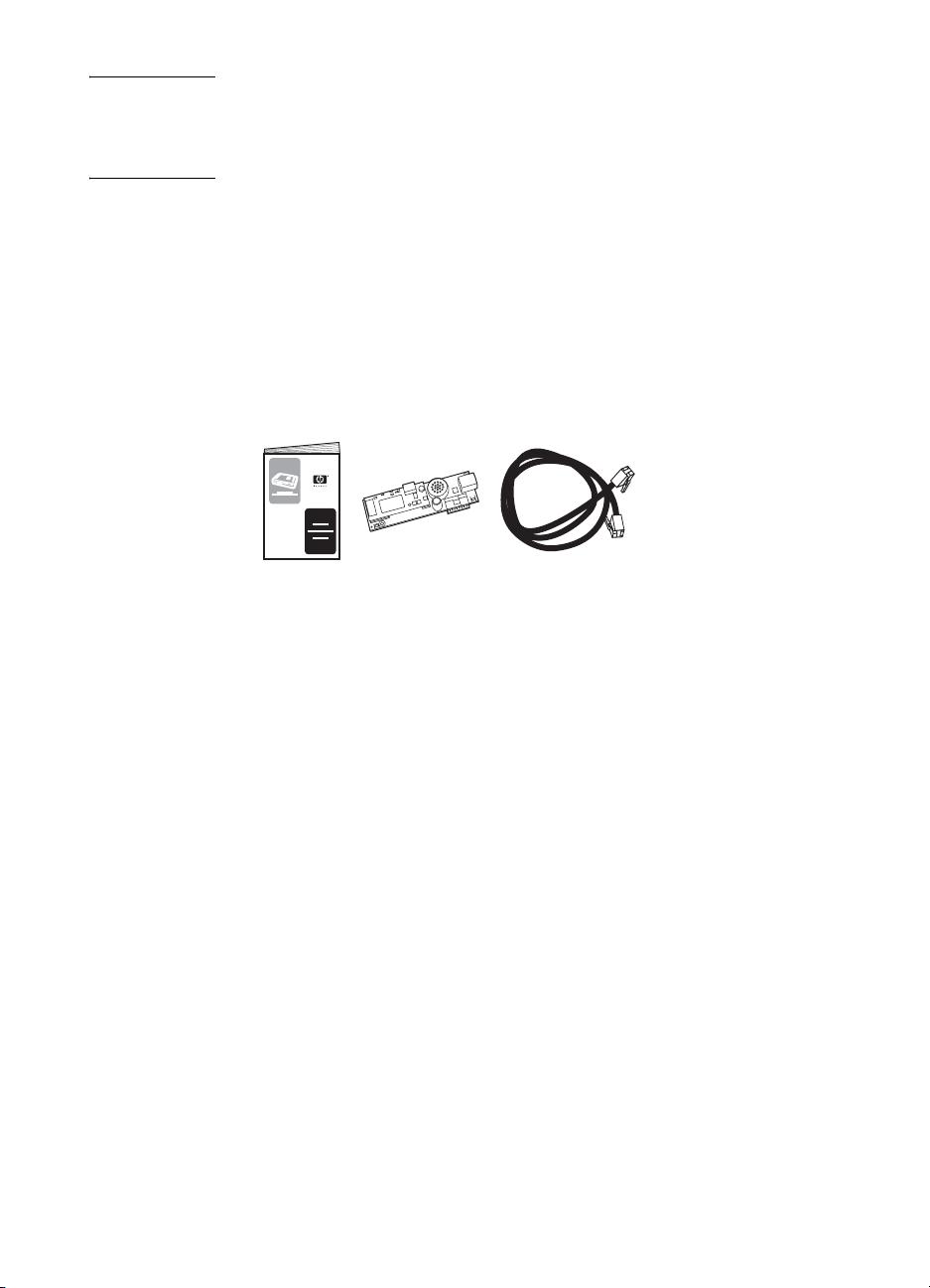
The following components are included with the fax accessory:
● Fax guide (this document)
● Fax accessory hardware card
● Phone cord(s) (cords vary depending on the country/region.)
Figure 1-1 HP LaserJet MFP Analog Fax Accessory 300 contents
Installing the fax accessory
This section describ es instal ling th e hardw are f ax ac cessory card into
the MFP. Procedures are provided for:
● HP LaserJet 9040/9050mfp
● HP LaserJet 4345mfp
Select the procedure for your MFP.
The HP LaserJet MFP Analog Fax Accessory 300 is also supported
in the HP LaserJet 9500mfp, however, the fax accessory is
pre-installed in the HP LaserJet 9500mfp. For information about
installing or replacing the fax accessory in the HP LaserJet 9500mfp,
refer to the HP LaserJet 9500mfp User Guide.
2 Chapter 1 Setting up ENWW
Page 11

Installing/replacing the fax accessory in the
HP LaserJet 9040/9050mfp
This procedure provides information on how to install or replace the
fax card in the HP LaserJet 9040/9050mfp.
Note If you purchased the MFP with the fax accessory installed, you do not
need to perform this hardware installation, however, you will need to
connect the phone cord as described in steps 10 and 11 of this
procedure and you will also need to make the required configuration
settings, see “Making required fax settings” on page 11.
The fax accessory card is installed on the MFP formatter board which
must be removed to install the fax card. To install or to replace an
existing fax card, complete the following steps.
1 Unpack the fax card from the box. Do not remove the fax card
from its antistatic pouch.
2 Set the MFP’s power switch to off and disconnect the AC power
cord.
3 Locate the formatter board. The formatter board is attached to a
sheet-metal plate (1) located on the left side of the MFP towards
the back, see Figure 1-2.
English
Figure 1-2 HP LaserJet 9040/9050mfp formatter location
ENWW Installing the fax accessory 3
Page 12
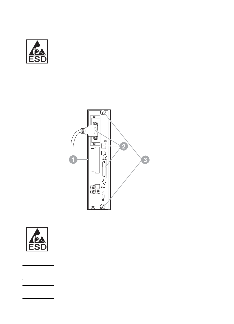
4 Disconnect all the cables (2) from the formatter (1), see Figure
1-3. Remember where the cables are removed from to ensure
that you reinstall them in the same locations.
The formatter board contains parts that are sensitive to electrostatic
discharge (ESD). When handling the formatter board, use static
protection, such as a grounding wrist strap connected to the metal
frame of the MFP or hold the metal frame with your hand. Also, avoid
touching the components on the board.
5 Loosen two captive thumb-screws (3) at the top and bottom of the
formatter plate, see Figure 1-3, and pull the formatter plate and
board (1) out of the MFP. Set the formatter board on a flat,
non-conductive surface.
Figure 1-3 HP LaserJet 9040/9050mfp formatter removal
The fax card contains parts that are sensitive to electrostatic
discharge (ESD). When removing the fax card from its antistatic
pouch and while installing it, use static protection such as a grounding
wrist strap connected a grounded metal component such as the metal
frame of the MFP, or touch the grounded metal frame with your hand.
Also, avoid touching the components on the board.
Note If you are replacing an existing fax card, remove the card that is to be
replaced from the formatter.
CAUTION While handling the fax card, do not press on the yellow component on
the card because this could damage it and result in a fax malfunction.
4 Chapter 1 Setting up ENWW
Page 13
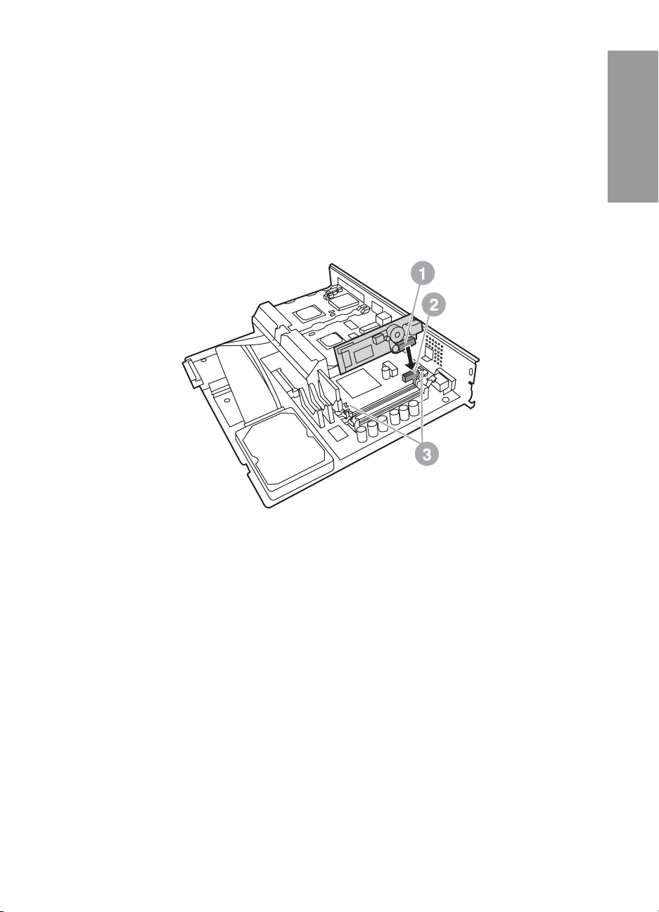
6 Remove the fax accessory from its antistatic pouch.
7 Insert the fax card connector (1) into the formatter fax connector
(2), see Figure 1-4. The connector on the formatter board is
labeled “FAX ACCESSORY.” When inserting the card into the
connector, the ends of the card should slide into the two board
guides (3) and “snap” into place when it is fully seated in the
connector.
Verify that the accessory is securely seated. The phone
connector on the fax card should be aligned with the opening in
the back of the formatter cage.
English
Figure 1-4 Installing the fax card on the HP LaserJet 9040/905 0mf p
formatter board
ENWW Installing the fax accessory 5
Page 14
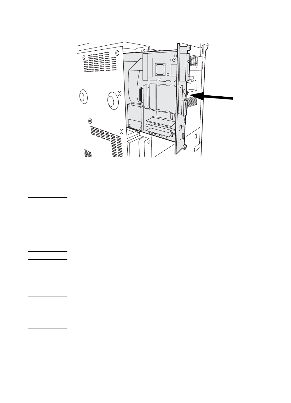
8 Install the formatter back into the MFP, see Figure 1-5.
Figure 1-5 Reinstalling the formatter into the HP LaserJet 9040/9050mfp
9 Reconnect any cables (4) removed from the formatter in step 4,
see Figure 1-6.
Note When connecting the fax card to a phone line, ensure that the phone
line being used is a dedicated line that is not used by any other devices.
This line should be an analog line because the fax will not function
correctly if connected to some digital PBX systems. If you are unsure
of what type of line you have, contact your telecom provider. Also, HP
recommends using the phone cord that comes with the fax accessory
to ensure the accessory functions correctly.
WARNING! The phone wall jack is electrified and you might receive an electric
shock if you touch the wall jack. When installing the phone cable, do
not touch the wall phone jack or, if you connect the phone cable into
the wall phone jack first, do not touch the wires on the phone cable
connector at other end.
10 Connect the phone cord connector (1) into the F AX connector (2)
on the formatter plate, see Figure 1-6. Push the connector in until
it “clicks.”
Note The LAN connector and the phone cord connector are similar. Ensure
that you connect the LAN cable plug (3) into the LAN connector and
the phone cord connector (1) into the FAX connector (2). Note that the
LAN connector is wider than the phone connector.
6 Chapter 1 Setting up ENWW
Page 15
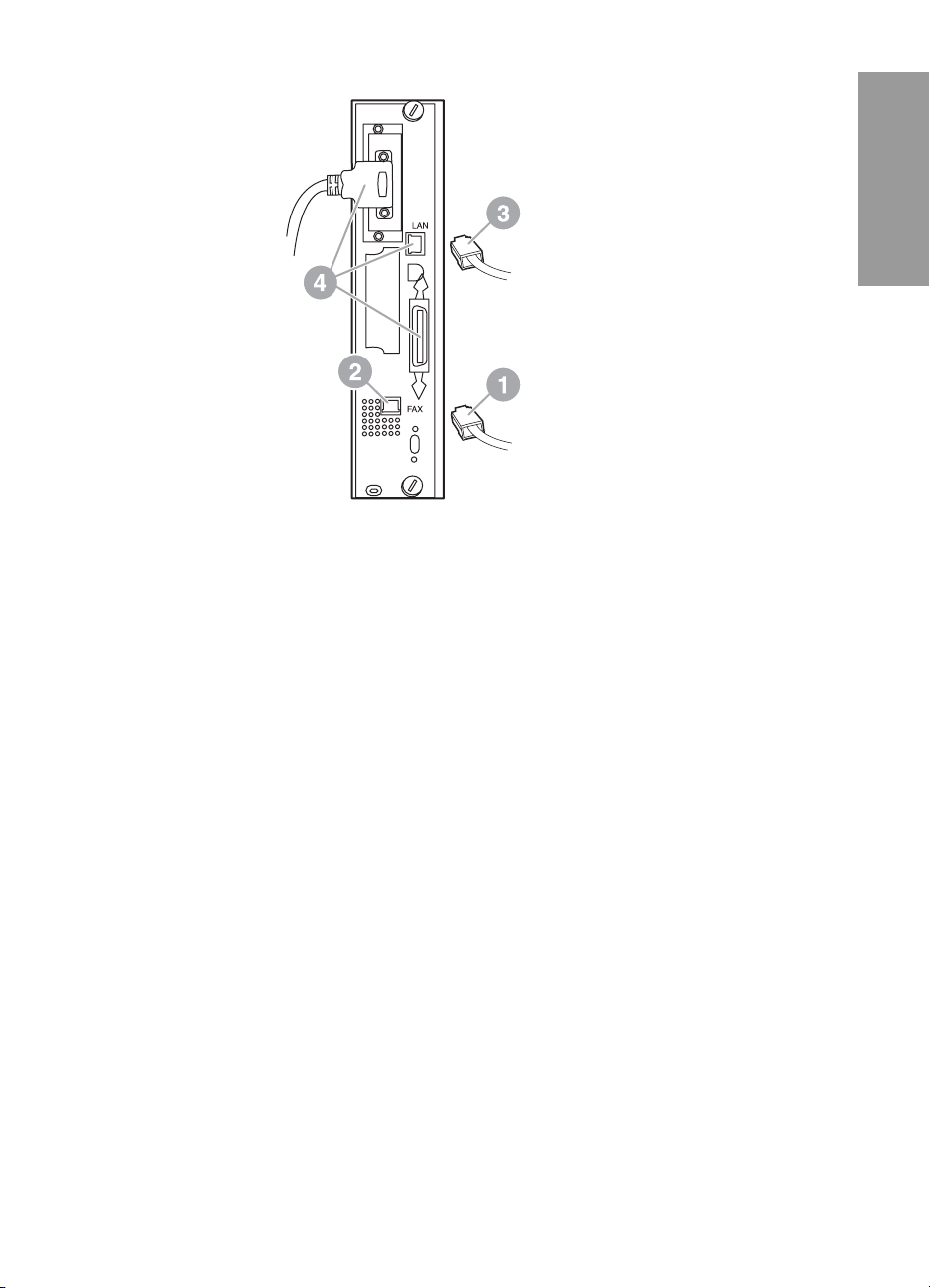
LAN Cable (if used)
Phone cord
Figure 1-6 Making cabling connections to the f or matte r f or the HP LaserJet
9040/9050mfp
11 Connect the other end of the phone cord into the phone jack on
the wall. Push the connector in until it “clicks.”
12 Plug in the MFP AC power cord and set the power switch to on.
This completes the installation of the fax card. Next, you need to
verify that the fax has been installed correctly and is operating, see,
“Verifying fax operation” on page 11.
English
Installing/replacing the fax accessory in the
HP LaserJet 4345mfp
This procedure provides information on how to install the fax card in
the HP LaserJet 4345mfp.
The fax card is installed on the MFP formatter board, which is
accessed by removing a MFP side panel. To install the fax card,
complete the following steps.
1 Unpack the fax card from the box, but do not remove it from its
antistatic pouch.
2 Set the MFP’s power switch to off and disconnect the AC power
cord.
3 Locate the formatter board (1) on the back of the printer, see
Figure 1-7.
ENWW Installing the fax accessory 7
Page 16
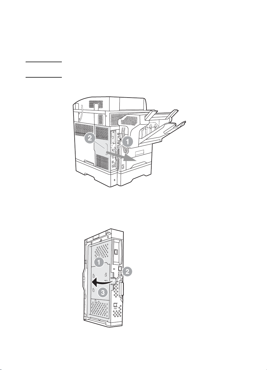
4 To access the formatter board, locate the removable cover (2) on
the side of the MFP, see Figure 1-7.
5 Remove the side cover by placing your fingers in the cover’s
indented area (2) and pulling, to slide it back and remove it from
the printer.
Note You do not need to remove any cables from the formatter for this
procedure.
Rear view
Figure 1-7 MFP formatter cover - HP LaserJet 4345mfp (rear view)
6 Open the formatter cage door (1) by pulling out on the door tab
(2) and swing (3) the door open, see Figure 1-8.
Figure 1-8 Formatter cage door - HP LaserJet 4345mfp
8 Chapter 1 Setting up ENWW
Page 17
The fax card contains parts that are sensitive to electrostatic
discharge (ESD). When removing the fax accessory from its antistatic
pouch and while installing it, use static protection, such as a
grounding wrist strap connected to a grounded metal frame of the
MFP or touch the metal frame of the MFP with your hand while
installing the fax card.
Note If you are replacing an existing fax card, remove the card that is to be
replaced from the formatter.
CAUTION While handling the fax card, do not press on the yellow component on
the card because this could damage it and cause a fax malfunction.
7 Remove the fax card from its antistatic pouch.
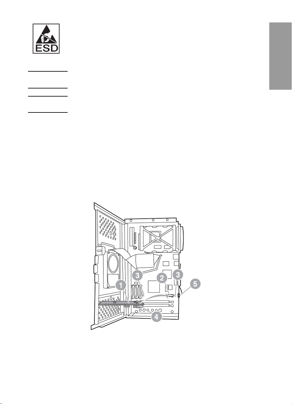
8 Insert the fax card connector (1) into the formatter fax connector
(2), see Figure 1-9. The connector (2) on the formatter board is
labeled “FAX ACCESSORY.” The ends of the card should slide
into the two guides (3) and the card should “snap” into place
when it is fully seated.
Verify that the accessory is securely seated. The phone
connector (4) on the fax card should be aligned with the opening
(5) in the back of the formatter cage, see Figure 1-9.
English
Figure 1-9 Installing the fax card on the formatter - HP LaserJet 4345mfp
ENWW Installing the fax accessory 9
Page 18
9 Close the formatter cage door and replace the MFP formatter
cover.
Note When connecting the fax accessory to a phone line, ensure that the
phone line being used for the fax accessory is a dedicated line that is
not used by any other devices. This line should be an analog line,
because the fax will not function correctly if connected to some digital
PBX systems. If you are unsure of what type of line you have, contact
your telecom provider. Also, HP recommends using the phone cord
that comes with the fax acce ssory to ensure that the accessory
functions correctly.
WARNING! The phone wall jack is electrified and you might receive an electric
shock if you touch the connector wires. When installing the phone
cable, do not touch the wall phone jack or, if you connect the phone
cable into the wall phone jack first, do not touch the wires on the
phone cable connector at other end.
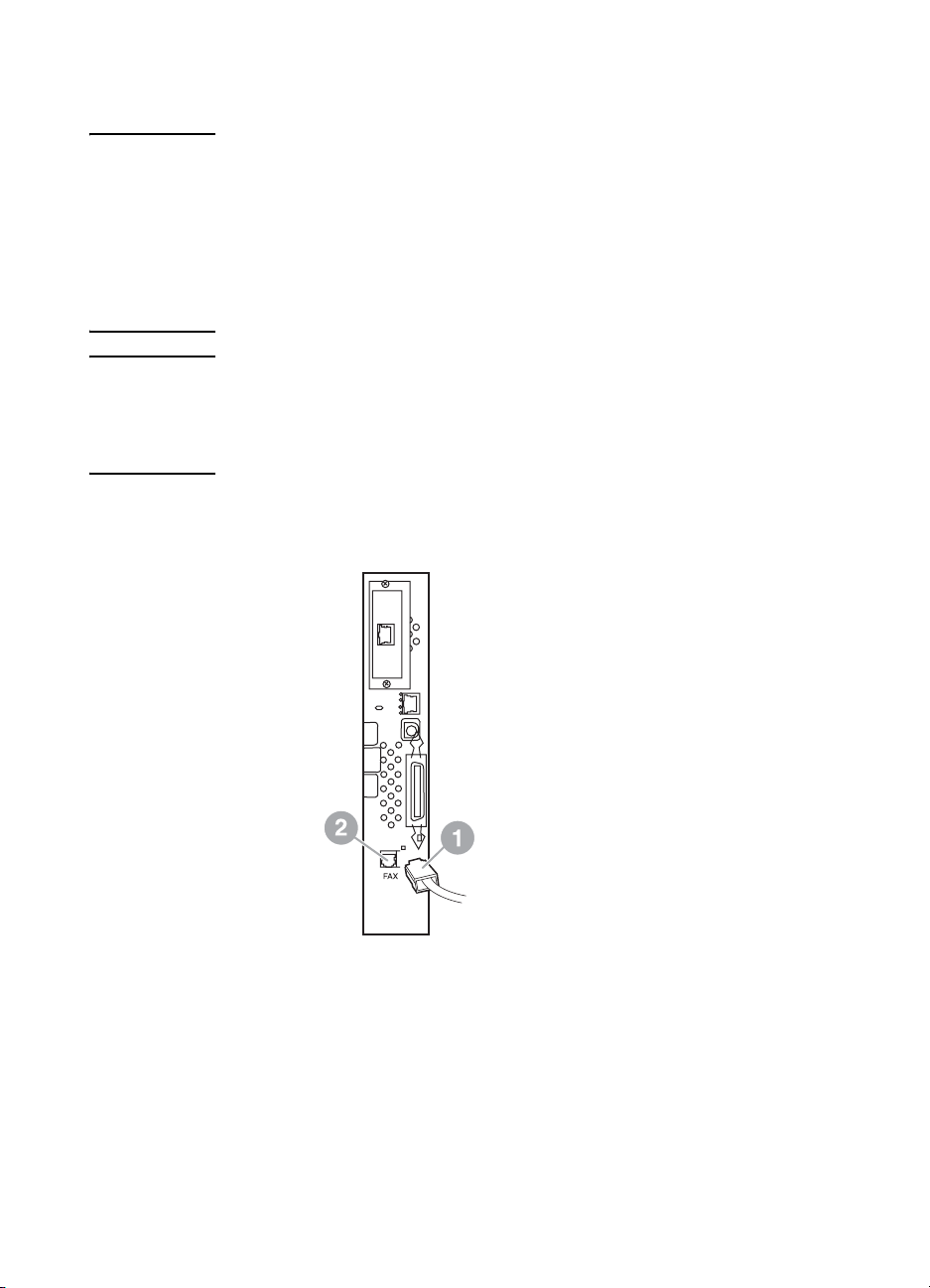
10 Connect one phone cord connector (1) into the FAX connector
(2), see Figure 1-10. Push it in until it “clicks.”
LAN Cable (if used)
Phone cord
Figure 1-10 Making cabling connections - HP LaserJet 4345mfp
11 Connect the other end of the phone cord into the phone jack on
the wall. Push the connector in until it “clicks.”
12 Plug the MFP AC power cord in and set the power switch to on.
This completes the installation of the fax card. Next, you need to
verify that the fax has been installed correctly and is operating, see,
“Verifying fax operation” on page 11.
10 Chapter 1 Setting up ENWW
Page 19

V erifying fax operation
When the fax accessory is installed and operating correctly, the fax
icon displays on the MFP control panel, see Figure 1-11. If the fax
accessory has just been installed but has not been configured, the
fax icon is grayed-out with Not Configured written across it. If this
occurs, the fax accessory needs to be configured, see “Making
required fax settings” on page 11.
Making required fax settings
Once the fax accessory is installed, you must make certain settings
before you can use the accessory. If these settings are not made, the
fax icon is displayed, grayed-out with Not Configured written across
it. These settings include:
● Date and time
● Location (country/region)
● Fax header (phone number and company name)
This information is used in the fax header, which is printed on all
outgoing faxes.
Note The fax accessory, when first installed, may read some of these
settings from the MFP, thus, a value may already be set. You should
check the values to verify that they are set and correct.
English
Note In the U.S. and many other countries/regions, setting the date, time,
location, phone number, and company name is a legal requirement for
fax.
ENWW Verifying fax operation 11
Page 20
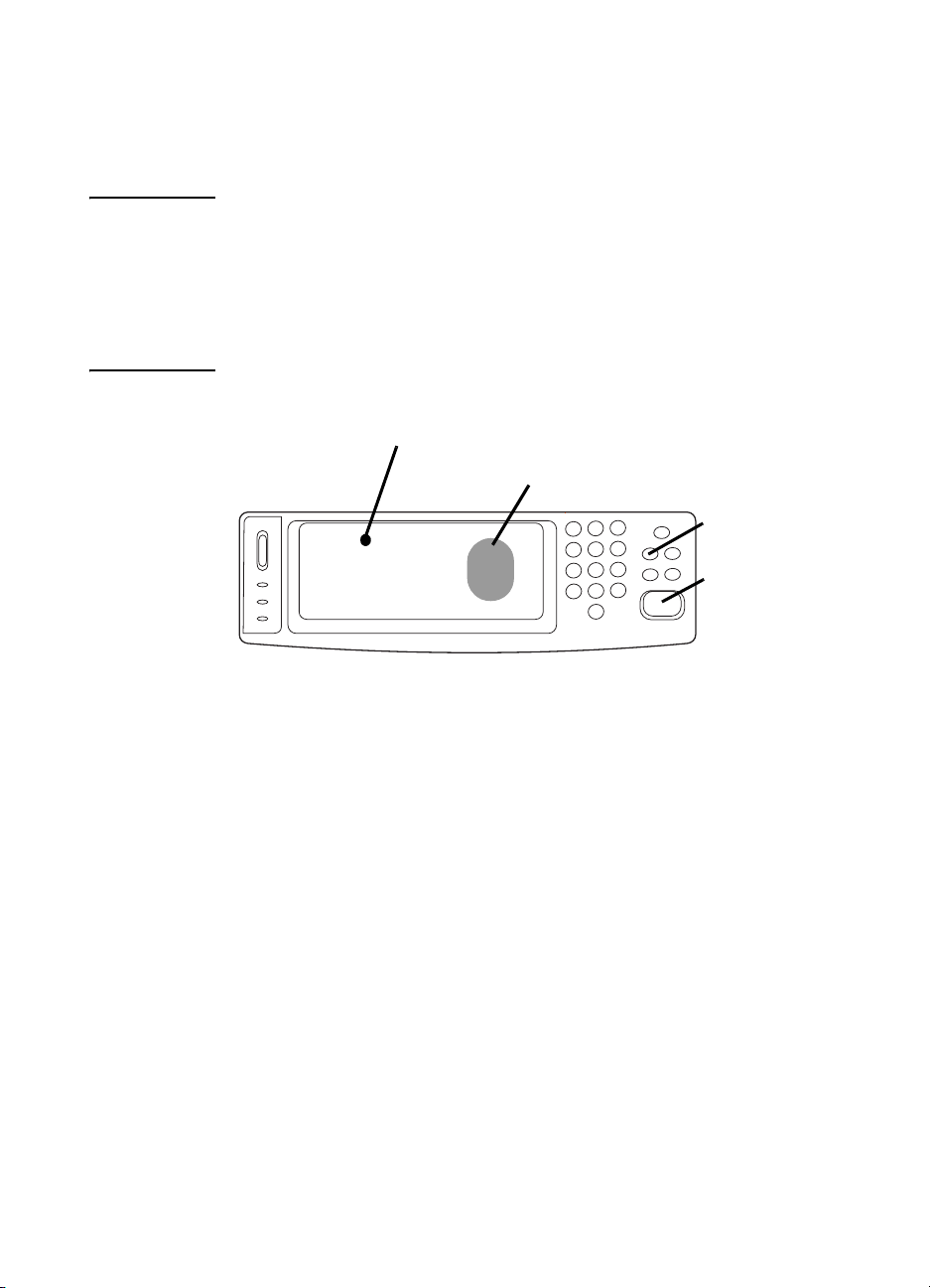
Accessing fax settings menu
The required fax settings are set using the fax settings menu. The fax
menu is accessed from the MFP control panel Menu button, see
Figure 1-11, “MFP control panel.”
Note If the fax menu settings do not appear in the menu listing, LAN fax may
be enabled. When LAN fax is enabled, the analog fax accessory is
disabled and the fax menu does not display . Only one fax feature, either
LAN fax or analog fax, can be enabled at a time. The fax icon displays
for either fax feature. If you wish to use analog fax when LAN fax is
enabled, use the HP MFP Digital Sending Software Configuration
Utility to disable LAN fax.
Touch-screen area
Fax icon
Menu button
Fax
Start button
Figure 1-11 MFP control panel
For detailed information on the operation of the MFP control panel,
see the MFP user guide.
To set or verify the date and time
The date and time setting for the fax accessory is the same value as
the MFP date and time setting. If this is the first time you are powering
up the MFP, you will prompted for this information.
To verify or change the date and time settings, complete the following
steps.
1 On the control panel, press the Menu button to display the main
menu.
2 Touch FAX to display the fax menu.
3 Touch FAX SETUP REQUIRED to display the required settings
menu.
4 Touch DATE/TIME to display the settings.
5 Select the date format and then enter the date.
12 Chapter 1 Setting up ENWW
Page 21

6 Select the time format and then enter the time.
7 Touch OK to accept the settings.
To set the location
The location setting identifies the country/region where the MFP/fax
accessory is located. This setting also sets the date/time format
and minimum/maximum rings-to-answer range for the country/region.
Because this setting is a legal requirement in some countries/regions,
it must be set for the fax accessory to operate. If this is the first time
you are powering up the printer, you will be prompted for this
information.
To verify or change the location, complete the following steps.
1 On the control panel, press the Menu button to display the main
menu.
2 Touch FAX to display the fax menu.
3 Touch FAX SETUP REQUIRED to display the required settings
menu.
4 Touch FAX HEADER to display the header settings.
5 Touch LOCATION to display the list of countries/regions.
6 Scroll through the list until your country/region is displayed, and
then touch the country/region to select it.
Note For Slovenia set the location to Hungary or Poland. For Morocco set
the location setting to Spain.
English
To set the fax header
The fax header setting is used to set a phone number and company
name that are placed in the fax header. This information is required
and must be set.
To verify or change the phone number and the company name,
complete the following steps.
1 On the control panel, press the Menu button to display the main
menu.
2 Touch FAX to display the fax menu.
3 Touch FAX SETUP REQUIRED to display the required settings
menu.
4 Touch FAX HEADER to display the settings.
5 Touch PHONE NUMBER to display the keyboard.
ENWW Making required fax settings 13
Page 22

6 Enter a phone number, and then touch OK to return to the Fax
Header menu.
7 Touch COMPANY NAME to display the keyboard.
8 Type the company name, and then touch OK to complete the
setting.
If the fax icon is displayed on the control panel screen and does not
have Not Configured written across, you have completed all
necessary setup. To send a fax, see Chapter 2, Faxing, for
information about sending faxes.
14 Chapter 1 Setting up ENWW
Page 23

Faxing
2
Introduction
This chapter provides information about fax setup, sending faxes, and
receiving faxes. This information includes:
● Fax feature screen
● Sending faxes
● Canceling a fax
● Changing notification settings
● Creating and deleting speed dial lists
● Assigning speed dial lists to one touch keys for the HP LaserJet
● Changing sharpness, background, and light/dark settings
● Receiving faxes
The HP LaserJet MFP Analog Fax Accessory 300 is supported in
the HP LaserJet 9500mfp, HP LaserJet 9040/9050mfp, and the
HP LaserJet 4345mfp. Operation of the fax accessory is slightly
different in the HP LaserJet 4345mfp. When the operation is different,
the procedure indicates the specific MFP model.
English
• Entering numbers manually
• Entering numbers using speed dial
• Entering numbers using the phone book feature
4345mfp
ENWW Introduction 15
Page 24
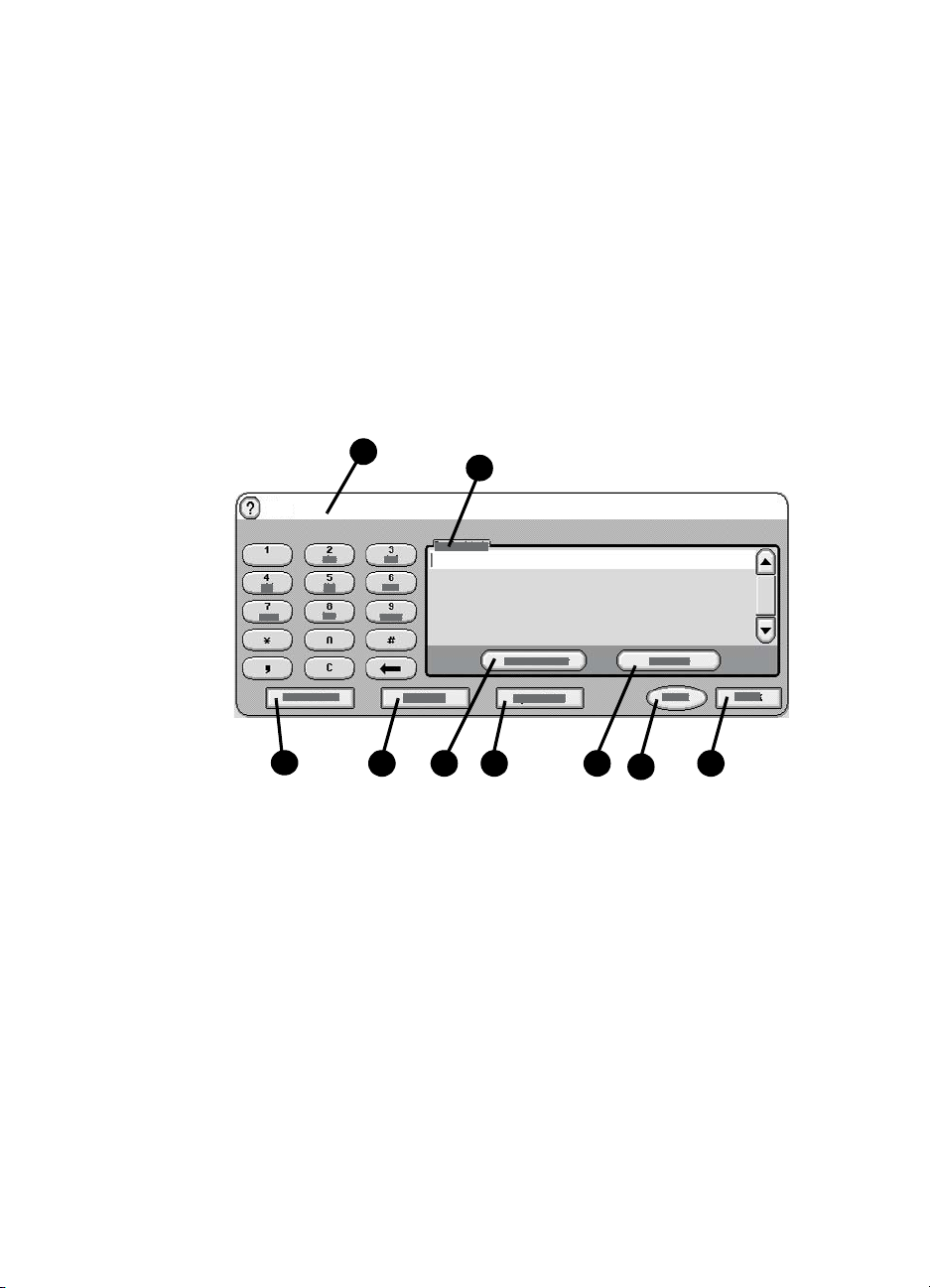
Fax feature scr e en
The Fax feature screen is used to send faxes. To access this screen,
press the Fax icon displayed on the MFP Home screen, see Figure
1-11, “MFP control panel” on page 12.
The main fax screen for the HP LaserJet 9040/9050mfp and HP
LaserJet 9500mfp products is slightly different than the main fax
screen for the HP LaserJet 4345mfp, as shown in the following two
figures.
Fax Feature screen for the
HP LaserJet 9040/9050mfp/9500mfp
2
Fax
3
1 Fax Recipients 6 Speed Dial
2 Status Message Bar 7 Remove
3 Phone Book
4 Settings 9 Back
5Next Number
4 5 6 9
1
7
* 8Start
8
*- Displays only if configured using HP MFP Digital
Sending Software Configuration Utility
Figure 2-1 Fax screen for the HP LaserJet 9040/9050mfp and 9500mfp
16 Chapter 2 Faxing ENWW
Page 25
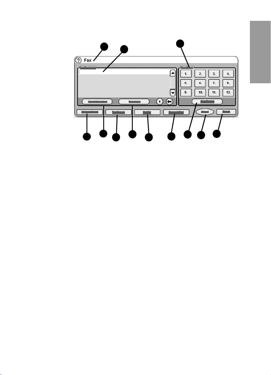
Fax Feature screen for the HP LaserJet 4345mfp
1
5
4
1 Status Message Bar 7 Remove
2 Fax Recipients 8 Notify
3 One Touch keys 9 Speed Dial
4 Phone Book
5 Next Number 11 Start
6 Settings 12 Back
2
7
6
8
* 10 Configure
3
10
9
11
*- displays only if configured using HP MFP Digital
Sending Software Configuration Utility
English
12
Figure 2-2 Fax screen for the HP LaserJet 4345mfp
Status message bar
While sending and receiving faxes, status information will display in
the status bar located at the top of some touch screens. This status
includes such information as: Ready, Receiving call, Page sent,
and others.
ENWW Status message bar 17
Page 26

Sending faxes
To send a fax, you can use one of three basic methods to enter
numbers:
● Enter number(s) manually.
● Enter number(s) using speed dial.
● Enter number(s) using the phone book (available only if HP MFP
Digital Sending Software Configuration Utility is installed and the
phone book has been populated).
Note For on-line information about sending a fax, touch ? on the screen to
access the help menu, and then touch Send a fax under the list of help
topics.
When entering a phone number from the numeric keypad, include
any pauses or other numbers, such as area codes, access codes for
numbers outside a PBX system (usually a 9 or 0), or a long-distance
prefix. A two second pause may be included by typing a comma (,).
If the fax prefix setting has been set to automatically include the
dialing prefix, you will not need to enter it, see “Setting a dialing
prefix” on page 41.
Note When a fax is sent, it is first scanned and stored into memory . After the
entire document is stored, it is sent and then deleted from memory.
Fax es that fail to send, because the number was busy or did not answer,
are deleted from memory . If Redial-On-Busy or Redial-On-No-Answer
are set, the fax will not be deleted until all retries fail.
To send a fax - enter number(s) manually
1 Place the document in the automatic document feeder (ADF) or
on the scanner glass.
2 From the main screen, touch the FAX icon. You may be
prompted to type a user name and password.
3 Touch Settings. Verify that the Describe Original settings match
those of your original. These settings include:
• Page si ze (such as letter or A4)
• 1-sided or 2-sided printing
• Page content (text, mixed text and graphics, or graphics and
photos) Sending graphics and photos in text mode results in
lower quality images.
• Orientation (portrait or landscape)
• Job Mode combines multiple scans into a single job.
18 Chapter 2 Faxing ENWW
Page 27

If the settings do not match, complete the following steps.
a Touch Describe Original to display the Original Setting
screen.
b Make any required changes to match your original.
c When all settings are completed, touch OK to return to the
Settings screen.
Note All settings made on the Settings screen are temporary settings,
enabled for the current fax only.
4 On the Settings screen touch Fax Settings to make adjustments
to the following settings:
• Sharpness - enhances image edges, see “Changing the
sharpness setting” on page 31.
• Background - to remove background the might result from a
copying color paper for example, see “Changing the
background setting” on page 31.
• Notify/Notification - to change how you are notified of the
status of the fax transmission, (that is, if the fax was sent
or if an error occurred and the fax was not sent). For the
HP LaserJet 4345mfp, access to the notification settings is
through the Notify button located on the main Fax screen.
For additional information, see “Changing notification settings”
on page 27.”
Note Notify/Notification changes the notification setting for the current fax
only. To change the default setting, see “To schedule fax call report
printing” on page 54.
English
When all settings are completed, touch OK to return to the
Settings screen.
5 On the Settings screen, to adjust the lightness/darkness of the
fax you are sending, touch the Light or Dark arrows.
6 When all settings are completed on the Settings screen, touch
OK to return to the Fax screen.
7 Using the keyboard, enter a phone number. To enter additional
numbers, touch Next Number and continue entering numbers.
To remove a number from the list, use the arrow keys to highlight
a number and then touch Remove.
ENWW Sending faxes 19
Page 28

Note If needed, enter a comma (,) to provide a two second pause after a
prefix number (such as a “9” or “0” ) to allow the internal phone system
time to access an outside line before the remainder of the number is
dialed.
8 Touch Start to send the fax. You can either touch the Start
button on the touch screen or press the green Start button on the
control panel.
Note If you have made any changes to the settings on the Settings screen
(such as changing notification or 1-sided to 2-sided), a Processing Job
screen displays asking “Would you like to keep your current settings?”.
If you press Yes, the MFP returns you to the Fax screen and the
settings you made are retained. This allows you to send another fax
using the same settings. If you press No, the settings are cleared
(returned to their default values) and the MFP home screen displays.
To send a fax using speed dial
Note Prior to sending a fax using speed dial, you must create a speed dial.
To create a speed dial, see “Creating and deleting speed dial lists” on
page 27.
To send a fax using the speed dial, complete the following steps.
1 Place the document in the automatic document feeder (ADF) or
on the scanner glass.
2 From the main screen, touch the FAX icon. You may be
prompted to type a user name and password.
3 Touch Settings. Verify that the Describe Original settings match
those of your original. These settings include:
• Page si ze (such as letter or A4)
• 1-sided or 2-sided printing
• Page content (text, mixed text and graphics, or graphics and
photos) Sending graphics and photos in text mode results in
lower quality images.
• Orientation (portrait or landscape)
• Job Mode combines multiple scans into a single job.
If the settings do not match, complete the following steps.
a Touch Describe Original to display the Original Setting
screen.
b Make any required changes to match your original.
20 Chapter 2 Faxing ENWW
Page 29

c When all settings are completed, touch OK to return to the
Settings screen.
Note All settings made on the Settings screen are temporary settings,
enabled for the current fax only.
4 On the Settings screen touch Fax Settings to make adjustments
to the following settings:
• Sharpness - resolution
• Background - to remove background the might result from a
copying color paper for example.
• Notify/Notification - to change how you are notified of the
status of the fax transmission, (that is, if the fax was sent or
if an error occurred and the fax was not sent). This setting for
the HP LaserJet 4345mfp is located on the main Fax screen.
For additional information, see “Changing notification settings”
on page 27.”
Note Notify/Notification changes the notification setting for the current fax
only. To change the default setting, see “To schedule fax call report
printing” on page 54.
When all settings are completed, touch OK to return to the
Settings screen.
5 On the Settings screen, to adjust the lightness/darkness of the
fax you are sending, touch the Light or Dark arrows.
English
6 When all settings are completed on the Settings screen, touch
OK to return to the Fax screen.
7 Touch Speed Dial to display the BASIC screen.
8 Touch the check box in front of the speed dial name you wish to
use.
9 Touch OK to return to the Fax screen. The speed dial number(s)
will be listed in the Fax Recipient screen.
10 Touch Start to send the fax. You can either touch the Start
button on the touch screen or press the green Start button on the
control panel.
ENWW Sending faxes 21
Page 30

Note If you have made any changes to the settings on the Settings screen
(such as changing notification or 1-sided to 2-sided), a Processing Job
screen displays asking “Would you like to keep your current settings?”.
If you press Yes, the MFP returns you to the Fax screen and the
settings you made are retained which allows you to send another fax
using the same settings. If you press No, the settings are cleared
(returned to their default values) and the MFP home screen is
displayed.
To send a fax using one touch speed dial
for the HP LaserJet 4345mfp
Note Prior to sending a fax using one touch speed dial key, you must first
create a speed dial, see “Creating and deleting speed dial lists” on
page 27, and then setup the one touch keys, see “To assign a speed
dial to a one touch key for the HP LaserJet 4345mfp” on page 30.
To send a fax using the one touch speed dial keys, complete the
following steps.
1 Place the document in the automatic document feeder (ADF) or
on the scanner glass.
2 From the main screen, touch the FAX icon. You may be
prompted to type a user name and password.
3 Touch Settings. Verify that the Describe Original settings match
those of your original. These settings include:
• Page si ze (such as letter or A4)
• 1-sided or 2-sided printing
• Page content (text, mixed text and graphics, or graphics and
photos) Sending graphics and photos in text mode results in
lower quality images.
• Orientation (portrait or landscape)
• Job Mode combines multiple scans into a single job.
If the settings do not match, complete the following steps.
a Touch Describe Original to display the Original Setting
screen.
b Make any required changes to match your original.
c When all settings are completed, touch OK to return to the
Settings screen.
Note All settings made on the Settings screen are temporary settings,
enabled for the current fax only.
22 Chapter 2 Faxing ENWW
Page 31

4 On the Settings screen touch Fax Settings to make adjustments
to the following settings:
• Sharpness - resolution
• Background Removal - to remove background that might
result from a copying color paper for example.
When all settings are completed, touch OK to return to the
Settings screen.
5 On the Settings screen, to adjust the lightness/darkness of the
fax you are sending, touch the Light or Dark arrows and touch
OK to return to the Settings screen.
6 When all settings are completed on the Settings screen, touch
OK to return to the Fax screen.
7 To change notification, touch Notify. Make changes to notification
settings and then touch OK to return to the Settings screen. For
additional information about notification, see “Changing
notification settings” on page 27.
Note Notify/Notification changes the notification setting for the current fax
only. To change the default setting, see “To schedule fax call report
printing” on page 54.
8 Touch the one touch speed dial key for the speed dial you want.
English
9 Touch Start to send the fax. You can either touch the Start
button on the touch screen or press the green Start button on the
control panel.
Note If you have made any changes to the settings on the Settings screen
(such as changing notification or 1-sided to 2-sided ), a Processing Job
screen displays asking “Would you like to keep your current settings?”.
If you press Yes, the MFP returns you to the Fax screen and the
settings you made are retained which allows you to send another fax
using the same settings. If you press No, the settings are cleared
(returned to their default values) and the MFP home screen is
displayed.
Sending a fax using phone book numbers
The fax phone book feature is available when the MFP is configured
to use the HP MFP Digital Sending Configuration software. If the
MFP has not been configured for use with this software, the Phone
Book button will not display. To configure the MFP for use with the
HP MFP Digital Sending Configuration software, see the HP MFP
Digital Sending Software User Guide or the HP MFP Digital Sending
Software Support Guide.
ENWW Sending faxes 23
Page 32

Also, when Authentication is enabled from the HP MFP Digital
Sending Configuration software, your personal fax numbers from
your Microsoft Exchange contact list appear in the phone book.
Note Fax numbers cannot be added or deleted from the phone book from
this device. Fax numbers can only be added or deleted using the
Address Book Manager (ABM) running on the Digital Send Server
or by changing the entries in your contact list.
To send a fax using the phone book, complete the following steps.
1 Place the document in the automatic document feeder (ADF) or
on the scanner glass.
2 From the main screen, touch the FAX icon. You may be
prompted to type a user name and password.
3 Touch Settings. Verify that the Describe Original settings match
those of your original. These settings include:
• Page si ze (such as letter or A4)
• 1-sided or 2-sided printing
• Page content (text, mixed text and graphics, or graphics and
photos) Sending graphics and photos in text mode results in
lower quality images.
• Orientation (portrait or landscape)
• Job Mode combines multiple scans into a single job.
If the settings do not match, complete the following steps.
a Touch Describe Original to display the Original Setting
screen.
b Make any required changes to match your original.
c When all settings are completed, touch OK to return to the
Settings screen.
Note All settings made on the Settings screen are temporary settings,
enabled for the current fax only.
4 On the Settings screen touch Fax Settings to make adjustments
to the following settings:
• Sharpness - resolution
• Background Removal - to remove background the might
result from a copying color paper for example.
24 Chapter 2 Faxing ENWW
Page 33

• Notify/Notification - to change how you are notified of the
status of the fax transmission, (that is, if the fax was sent
or if an error occurred and the fax was not sent). For the
HP LaserJet 4345mfp, access to the notification settings is
through the Notify button located on the main Fax screen.
Note Notify/Notification changes the notification setting for the current fax
only. To change the default setting, see “To schedule fax call report
printing” on page 54
When all settings are completed, touch OK to return to the
Settings screen.
5 On the Settings screen, to adjust the lightness/darkness of the
fax you are sending, touch the Light or Dark arrows.
6 When all settings are completed on the Settings screen, touch
OK to return to the Fax screen.
Note When you use the Phone Book, names instead of numbers appear in
the fax recipients list.
7 Touch Phone Book to display the Fax Phone Book screen.
8 Use the scroll arrows to highlight a name or a number in the list,
and then touch Add to enter the name/number in the window.
You can add as many names/numbers as you want.
The Details button displays the fax number or list of fax numbers
for the selected phone book entry. The Personal button shows
only entries from the user's contact list in the phone book. The
All button provides a merged list of the public fax entries and the
personal entries from the contact list.
English
9 Touch OK to return to the Fax screen. The list of fax names is
displayed in the Recipients window.
10 Touch Start to send the f ax. You can ei ther, touch the Start button
on the touch screen or press the green Start button on the
control panel.
Note If you have made any changes to the settings on the Settings screen
(such as changing notification or 1-sided to 2-sided), a Processing Job
screen displays asking “Would you like to keep your current settings?”.
If you press Yes, the MFP returns you to the Fax screen and the
settings you made are retained which allows you to send another fax
using the same settings. If you press No, the settings are cleared
(returned to their default values) and the MFP home screen is
displayed.
ENWW Sending faxes 25
Page 34

Canceling a fax
To cancel the current fax transmission
The Cancel Current Transmission menu item only appears if an
outgoing fax call is in progress.
Note The cancel operation may require up to 30 seconds to complete.
1 On the control panel, press the Menu button to display the main
menu.
2 Touch FAX to display the fax menu.
3 Touch CANCEL CURRENT TRANSMISSION to cancel the fax.
Note While a fax or faxes are being deleted, a canceling fax message
displays in the status bar.
To cancel all pending faxes
This deletes all outgoing faxes stored in memory. However, if a fax is
in the process of being transmitted, that fax is not deleted and will
be sent.
Note If other outgoing faxes are waiting in memory , they will also be deleted.
1 On the control panel, press the Menu button to display the main
menu.
2 Touch FAX to display the fax menu.
3 Touch CANCEL ALL PENDING TRANSMISSIONS to cancel all
stored faxes.
26 Chapter 2 Faxing ENWW
Page 35

Changing notification settings
Notification selects when and how you are notified of the status of an
outgoing fax. This setting applies to the current fax only. To change
the setting permanently , change the default setting, see “To schedule
fax call report printing” on page 54.
To change how you are notified, perform the following steps.
1 On the control panel main screen, touch the FAX icon to display
the Fax screen.
2 Perf orm the following step for your MFP:
• HP LaserJet 9040/9050mfp/9500mfp - Touch Settings to
display the Settings screen and go to step 3.
• HP LaserJet 4345mfp - Touch Notify button and go to step
and go to step 4.
3 Touch the Fax Settings icon to display the Fax Settings screen.
4 Under the NOTIFY tab:
• Touch NONE to turn off notification, and then touch OK, to
complete the setting and return to the Fax feature screen.
• Touch THIS JOB or ON ERROR to enable notification and
continue to the next step.
5 Touch PRINT to receive a printed notification and complete the
notification process, or, touch E-MAIL to display the keyboard.
English
Note E-mail notification works if E-mail has been configured. If the E-Mail
icon on the MFP screen has “Not Available” across it, E-mail is not
configured. To configure E-mail, use the MFP E-mail menu settings,
see the MFP user documentation for detailed information on
configuring E-ma il .
6 If you selected E-mail, use the keyboard to type an e-mail
address, and then touch OK to complete the notification setting
and to return to the Fax menu.
Creating and deleting speed dial lists
Speed dial allows you to assign a speed dial name to a single number
or a group of numbers and then send a fax to that number or numbers
by selecting the speed dial name.
ENWW Changing notification settings 27
Page 36

To create a speed dial list
1 On the control panel main screen, touch the FAX icon to display
the Fax screen.
2 Touch Speed Dial to display the Speed Dial screen.
3 Touch the EDIT tab to display the Edit screen.
4 Touch New Speed Dial icon to display the New Speed Dial
screen.
5 Type a number using the key pad. If you wish to enter more than
one number, touch Next Number and enter another number.
Repeat this step to enter all the numbers for the speed dial.
6 Touch the Name button to display the keyboard.
7 Type a name for the speed dial using the keyboard, and then
touch OK to return to the New Speed Dial screen.
8 Touch OK to accept the speed dial.
Note For the HP LaserJet 9040/9050mfp and HP LaserJet 9500mfp, once
a speed dial is created, you cannot add or delete individual numbers
from the list. For the HP LaserJet 4345mfp, once a speed dial is
created, you can delete individual numbers from the list.
To delete a speed dial list for the
HP LaserJet 9040/9050mfp and 9500mfp
1 On the control panel main screen, touch the FAX icon to display
the Fax screen.
2 Touch Speed Dial to display the Speed Dial screen.
3 Touch the EDIT tab to display the Edit screen.
4 Touch the Delete Speed Dial icon to display the Delete Speed
Dial screen.
5 Touch the check box in front of the speed dial you wish to delete.
6 Touch Delete to delete the speed dial list.
7 Touch Yes to confirm the deletion; or, touch No to retain the list.
8 Touch OK to return to the Fax screen.
28 Chapter 2 Faxing ENWW
Page 37

To delete a speed dial list for the
HP LaserJet 4345mfp
1 On the control panel main screen, touch the FAX icon to display
the Fax screen.
2 Touch Speed Dial to display the Speed Dial screen.
3 Touch the EDIT tab to display the Edit screen.
4 Touch the Delete Speed Dial icon to display the Delete Speed
Dial screen.
5 Touch the check box in front of the speed dial you wish to delete.
You may need to use the scroll arrows to display the speed dial
name. You can delete more than one speed dial list by placing a
check mark in front of other names.
6 Touch Delete All to delete the speed dial list.
7 Touch Yes to confirm the deletion and return to the Delete Speed
Dial screen; or, touch No to retain the list.
8 Touch OK to return to the Fax screen.
To delete a single number from a speed dial list
for the HP LaserJet 4345mfp
English
1 On the control panel main screen, touch the FAX icon to display
the Fax screen.
2 Touch Speed Dial to display the Speed Dial screen.
3 Touch the EDIT tab to display the Edit screen.
4 Touch the Delete Speed Dial icon to display the Delete Speed
Dial screen.
5 Touch the check box in front of the speed dial which holds the
number you wish to delete. You may need to use the scroll
arrows to display the speed dial name.
6 Touch Details to display the list of numbers for the speed dial.
7 Use the up and down scroll arrows to highlight a number to
delete.
8 Touch Delete to display the confirmation screen.
9 Touch Yes to confirm the deletion; or touch No to retain the
number.
10 Touch OK to return to the Fax screen.
ENWW Creating and deleting speed dial lists 29
Page 38

Assigning speed dial lists to one touch keys
for the HP LaserJet 4345mfp
The one touch key pad allows you to send a fax to a speed dial list
simply by touching a one touch key. However, prior to using the one
touch keys, you must create a speed dial list and assign the speed
dial name to a one touch key.
To assign a speed dial to a one touch key
for the HP LaserJet 4345mfp
Before you can use the one touch keys you must assign a speed dial
name to a one touch key.
To assign a speed dial list name to a one touch key, complete the
following steps.
1 Create a speed dial, see “Creating and deleting speed dial lists”
on page 27.
2 Touch Configure on the fax screen to display the One Touch
Button Configuration screen.
3 Touch any (Available) number you wish to assign to the speed
dial.
4 On the Speed Dial screen touch the Edit tab and select the
speed dial check box you wish to assign to the key, and then
touch OK.
5 A screen displays to verify the name you selected and button
number:
• Touch OK to accept the selection, or
• Touch Cancel to return to the One Touch Button Configuration
screen, or
• Touch Reassign to reassign another speed dial name to the
the key.
6 Touch OK to accept the settings.
To clear or reassign speed dial lists
to one touch keys for the HP LaserJet 4345mfp
If you wish to remove a speed dial list from a one touch button,
perform the following steps.
1 Touch Configure on the one touch key pad to display the One
Touch Button Configuration screen.
2 Touch number key with the speed dial name you wish to remove.
30 Chapter 2 Faxing ENWW
Page 39

3 The “Button is already configured” screen displays. Touch Clear
to remove the speed dial name from the one touch button; or,
touch Reassign to assign a different speed dial name to the key;
or, touch Cancel to return to the One Touch Button Configuration
screen.
4 Touch OK to accept the settings.
Changing the sharpness setting
The Sharpness setting specifies the sharpness that the scanner uses
when the MFP scans your original. Sharpness enhances the edges of
the original so that faint or fine text and graphics are reproduced more
sharply. Increasing sharpness increases resolution which also
increases transmission time.
To change the sharpness setting, perform the following steps.
1 On the control panel main screen, touch the FAX icon to display
the Fax screen.
2 Touch Settings to display the Settings screen.
3 Touch the Fax Settings icon to display the Fax Settings screen.
4 Under ENHANCE, touch the left arrow to decrease the sharpness
or touch the right arrow to increase the sharpness of the image.
5 Touch OK to accept the setting.
Changing the background setting
If you are faxing a document that is printed on colored paper, you can
enhance your fax copy quality by removing the background that might
cause your fax copy to streak or blur.
To change the background setting, perform the following steps.
English
1 On the control panel main screen, touch the FAX icon to display
the Fax screen.
2 Touch Settings to display the Settings screen.
3 Touch the Fax Settings icon to display the Fax Settings screen.
4 Under the ENHANCE tab, touch the left arrow to increase
background or touch the right arrow to decrease the background.
5 Touch OK to accept the setting.
ENWW Changing the sharpness setting 31
Page 40

Changing the light/dark setting
The light/dark setting adjusts how light or dark the transmitted image
will appear on the recipient fax machine.
To change the light/dark setting, perform the following steps.
1 On the control panel main screen, touch the FAX icon to display
the Fax screen.
2 Touch Settings to display the Settings screen.
3 Touch the Light arrow to lighten the image or touch the Dark
arrow to darken the image.
4 Touch OK to accept the setting.
Receiving faxes
When the fax accessory receives incoming faxes, it stores them in
memory before printing. Once the entire fax is stored, it is printed
and then deleted from memory. Faxes print when received, unless
Schedule Printing of Faxes is enabled. If Schedule Printing of Faxes
is enabled, all incoming faxes are stored in memory and not printed.
When Schedule Printing of Faxes is disabled, all stored faxes print,
see “Scheduling fax printing (memory lock)” on page 49.
You can change the fax receive default settings to modify the way a
fax is received. These settings include:
● Selecting the number of rings-to-answer
● Printing date, time, and page number on faxes (stamp)
● Selecting input paper tray and destination bin
● Forwarding faxes to another number
● Blocking faxes from certain numbers
● Schedule printing of faxes (memory lock)
For information on changing these menu settings, see Chapter 3,
“Configuration” on page 33 and Chapter 4 “Faxing (advanced)” on
page 47.
Note You cannot ca ncel inc om ing faxes.
32 Chapter 2 Faxing ENWW
Page 41

Configuration
3
Introduction
This chapter describes the configuration settings for the MFP fax
accessory that you access through the fax menu on the control panel.
In addition to the control panel, you can access these settings though
remote configuration tools, as described below.
Note The following fax settings are described in Chapter 1 and are not
included here. For information about these settings, see Chapter 1
- Canceling faxes
- Setting the date and time
- Setting the location
- Setting the header
English
Remote fax configuration
In addition to the MFP control panel, you can configure the fax
accessory remotely using various software tools. Because the MFP
contains an embedded web server (EWS), you can configure the fax
accessory across the web using either a web browser or HP Web
Jetadmin (WJA). In addition, you can configure the fax accessory
across the network with a network-connected PC using the HP MFP
Digital Sending Software Configuration Utility (DSS). These tools
provide access to most of the fax accessory configuration settings
available from the MFP fax menu, described in this document.
ENWW Introduction 33
Page 42

Note The DSS configuration utility can disable/enable the analog fax feature
on the MFP . If the analog fax is disabled by the DSS configuration utility
and then the MFP is detached from the configuration utility , you will not
see Send to Fax in the EWS or WJA Digital Sending menu. If this
happens, to enable the analog fax for the MFP, you must use the
DSS configuration utility.
Web browser
As mentioned above, the MFP contains an EWS. The EWS allows
you to use a web browser to access and set the analog fax settings,
described in this chapter.
To use a web browser to access the EWS fax setting screens,
perform the following steps.
1 Type the IP address of the MFP in the browser URL address bar
and press return to display the EWS Configure MFP screen. To
get the IP address of the MFP, print an MFP Configuration page.
Note If DSS is being used, a message appears on EWS indicating that DSS
is in control. The only way to change settings is through DSS.
2 Select the Digital Sending tab.
3 Select the Send to Fax tab to display the Fax configuration
settings screen.
4 On the Fax Settings screen make any changes to the settings
and select OK to accept the settings. Select Advanced to display
the Advanced MFP Modem Settings screen for additional fax
settings. For information about the settings, see the setting
descriptions in this guide.
5 After you have made changes to the settings, select OK to accept
the settings.
HP Web Jetadmin
To access the MFP analog fax settings using HP Web Jetadmin,
perform the following steps. For detailed information on HP Web
Jetadmin, see the HP Web Jetadmin Reference Manual.
Note For HP Web Jetadmin to access the MFP Digital Sending configuration
pages, which contain the fax settings, the hpjdigsending.fpm plug-in
must be installed. If you do not have this plug-in, you can download it
from
www.hp.com. See the HP Web Jetadmin Reference Manual for
information on installing plug-ins.
34 Chapter 3 Configuration ENWW
Page 43

1 Start HP Web Jetadmin.
2 In the At a Glance text box, type the IP address of the MFP in the
Quick Device Find text box, and then select GO to display the
device status in the right pane. Select Digital Sending from the
status drop-down menu in that pane.
3 Under the Digital Send Settings menu, select Send to Fax to
display the Fax Settings Screen.
4 On the Fax Settings screen make any changes to the settings,
and then select OK to accept the settings. Select Advanced to
display the Advanced MFP Modem Settings screen for additional
fax settings.
For information about the settings, see the descriptions in this
guide.
5 After you have made changes to the settings, select OK to accept
the settings.
In addition to configuring a single MFP, you can also perform multiple
device configuration. Multiple device mode configures several MFPs
at once. For information on this feature, see the HP Web Jetadmin
Reference Manual.
HP MFP Digital Sending Software Configuration
Utility
English
To access the analog MFP fax settings using DSS configuration
utility, perform the following steps.
1 Start the utility (on the PC or server) to display the main screen.
2 Select the MFP and click the Configure MFP button from the
main screen, and then select the Send to Fax tab to display the
Fax Settings screen.
3 To enable the fax capabilities on the MFP, check Enable Send to
Fax. To access Analog Fax settings, select directly from the
mfp’s internal modem from the Send Faxes... drop-down list.
On the Fax Settings screen make any changes to the settings
and select OK to accept the settings. Select Advanced to display
the Advanced MFP Modem Settings screen for additional fax
settings.
For information about these settings, see the setting descriptions
in this guide.
4 After you have made changes to the settings, select OK to accept
the settings.
ENWW Remote fax configuration 35
Page 44

In addition to configuring a single MFP, you can also configure
multiple devices. For more information on the HP MFP Digital
Sending Software Configuration Utility, see the HP MFP Digital
Sending Software User Guide or the HP MFP Digital Sending
Software Support Guide.
Note Depending on the capabilities and settings of your fax method, some
of these options may not be available or configurable.
Setting the modem volume
To set the modem volume, perform the following steps.
1 On the control panel, press the Menu button to display the
main menu.
2 Touch FAX to display the fax menu.
3 Touch FAX SETUP OPTIONAL to display the optional
settings menu.
4 Touch MODEM VOLUME to display the volume settings.
5 Touch OFF, MEDIUM (default), or LOUD to set the volume.
Setting the ringer volume
To set the ringer volume, perform the following steps.
1 On the control panel, press the Menu button to display the
main menu.
2 Touch FAX to display the fax menu.
3 Touch FAX SETUP OPTIONAL to display the optional
setup items.
4 Touch RINGER VOLUME to display the settings.
5 Touch OFF, MEDIUM (default), or LOUD to change the volume.
Setting error correction mode
Normally, the fax accessory monitors the signals on the telephone
line while it is sending or receiving a fax. If the fax accessory detects
an error during the transmission and the error correction setting is on,
the fax accessory can request that the error portion of the fax be sent
again.
36 Chapter 3 Configuration ENWW
Page 45

You should turn off error correction only if you are having trouble
sending or receiving a fax and if you are willing to accept the errors in
the transmission. Turning off the setting might be useful when you are
trying to send a fax overseas or receive one from overseas, or if you
are using a satellite telephone connection.
To enable or disable error correction mode, perform the following
steps.
1 On the control panel, press the Menu button to display the
main menu.
2 Touch FAX to display the fax menu.
3 Touch FAX SETUP OPTIONAL to display the optional
setup items.
4 Touch ERROR CORRECTION MODE to display the settings.
5 Touch ON (default) to enable error correction mode, or touch
OFF to disable correction mode.
Setting JBIG compression mode
Enabling JBIG compression can reduce phone call charges by
reducing fax transmission time and is, therefore, the preferred setting.
However, JBIG may cause compatibility problems when
communicating with some older fax machines, in which case you
may need to disable it.
English
Note JBIG compression only works when both, the sending and receiving
machines have JBIG compression.
To enable or disable JBIG compression, perform the following steps.
1 On the control panel, press the Menu button to display the main
menu.
2 Touch FAX to display the fax menu.
3 Touch FAX SETUP OPTIONAL to display the optional setup
items.
4 Touch JBIG COMPRESSION to display the settings.
5 Touch ON to enable JBIG compression, or touch OFF (default) to
disable JBIG compression.
ENWW Setting JBIG compression mode 37
Page 46

Setting outgoing fax resolution
The outgoing fax resolution setting determines the maximum
resolution supported by the receiving fax. The fax accessory uses
the highest possible resolution, limited by this setting, and the
maximum resolution of the receiving fax.
Note Fax es wider than 21.25 cm (8.5 inches), will automatically be sent using
standard or fine, to reduce phone time.
To set the resolution, perform the following steps.
1 On the control panel, press the Menu button to display the main
menu.
2 Touch FAX to display the fax menu.
3 Scroll down and touch FAX SEND.
4 Touch DEF AULT RESOLUTION to display the resolution
settings.
5 Touch STANDARD (200 x 100 dpi), FINE (200 x 200 dpi;
default), or SUPERFINE (300 x 300 dpi) to select the resolution.
Note The higher the resolution, the longer the transmission time required.
Setting the overlay header (outgoing faxes)
The overlay header consists of the date, time, company name, phone
number, and page number and is printed at the top of the page on
outgoing faxes. This setting determines whether the header is
appended to the top of the page or is printed as an overlay. If the
header is appended to the top of a page, it moves page data down
which can result in data at the bottom of a page being pushed to
another page, possibly printing an additional page. If the header is
printed as an overlay, it does not push any page data, but may print
over data at the top of the page.
Note When fax forwarding is enabled, the overlay header is always
appended to the top of the page, even if overlay is enabled.
To select how the header is printed, perform the following steps.
1 On the control panel, press the Menu button to display the
main menu.
2 Touch FAX to display the fax menu.
3 Scroll down and touch FAX SEND.
38 Chapter 3 Configuration ENWW
Page 47

4 Touch OVERLAY HEADER to display the header settings.
5 Touch YES to print the header as an overlay, or touch NO
(default) to append the header to the top of the page.
Setting dialing mode
The dialing mode setting sets the type of dialing used, either tone
(touch-tone phones) or pulse (rotary-dial phones).
To set dialing mode, perform the following steps.
1 On the control panel, press the Menu button to display the
main menu.
2 Touch FAX to display the fax menu.
3 Scroll down and touch FAX SEND. Use the down arrow key to
scroll to DIALING MODE.
4 Touch DIALING MODE to display the dialing mode settings.
5 Touch TONE (default) to set the fax for tone dialing, or touch
PULSE to set the fax for pulse dialing.
Setting redial rules
To set redial-on-busy
The redial-on-busy setting selects the number of times (0 through 9)
the fax accessory redials a number when it is busy. The interval
between retries is set by the Redial Interval setting.
English
1 On the control panel, press the Menu button to display the
main menu.
2 Touch FAX to display the fax menu.
3 Scroll down and touch FAX SEND.
4 Touch REDIAL ON BUSY to display the redial-on-busy setting
screen.
5 Use the up and down arrows to select the number (default=3),
and then touch OK.
To set redial-on-no-answer
The redial-on-no-answer setting selects the number of times the fax
accessory redials if the number dialed does not answer. The number
of retries is either 0 to 1 (used in U.S.) or 0 to 2, depending on the
country/region setting. The interval between retries is set by the redial
interval setting.
ENWW Setting dialing mode 39
Page 48

1 On the control panel, press the Menu button to display the
main menu.
2 Touch FAX to display the fax menu.
3 Scroll down and touch FAX SEND.
4 Scroll down and touch REDIAL ON NO ANSWER to display the
setting screen.
5 Use the up and down arrows to select the number (default=0),
and then touch OK.
To set redial interval
The redial interval setting selects the number of minutes between
retries if the number dialed is busy or not answering.
1 On the control panel, press the Menu button to display the
main menu.
2 Touch FAX to display the fax menu.
3 Scroll down and touch FAX SEND.
4 Scroll down and touch REDIAL INTERVAL to display
setting screen.
5 Use the up and down arrows to select the number (1 through
5 minutes; default=5), and then touch OK.
Setting dial tone detection
The detect dial tone setting determines whether the fax checks for a
dial tone before sending a fax.
To enable or disable dial tone detection, perform the following steps.
1 On the control panel, press the Menu button to display the
main menu.
2 Touch FAX to display the fax menu.
3 Scroll down and touch FAX SEND.
4 Scroll down and touch DETECT DIAL TONE to display the detect
dial tone settings.
5 Touch ON (default) to enable dial tone detection, or touch OFF to
disable dial tone detection.
40 Chapter 3 Configuration ENWW
Page 49

Setting a dialing prefix
The dialing prefix setting allows you to enter a prefix number (such as
a “9” to access an outside line) when dialing. This prefix number is
automatically added to all phone numbers when dialed.
To set a dialing prefix, perform the following steps.
Note You may need a pause between the prefix and the phone number. To
insert a two second pause, enter a comma (,).
1 On the control panel, press the Menu button to display the main
menu.
2 Touch FAX to display the fax menu.
3 Scroll down and touch FAX SEND.
4 Scroll down and touch DIAL PREF IX to display the prefix
settings.
5 Touch OFF (default) to disable dialing prefix, or touch CUSTOM
to display the keyboard, and type a prefix.
6 Type the prefix number(s), and then touch OK.
Setting billing codes
English
The billing code setting, when enabled, prompts the user to enter a
number when sending a fax. This number is placed in the billing code
report. To view the billing code report, you can either print the report,
see “Printing the billing code report” on page 55, or query it using an
application.
To set billing codes, perform the following steps.
1 On the control panel, press the Menu button to display the main
menu.
2 Touch FAX to display the fax menu.
3 Scroll down and touch FAX SEND to display the Fax Send
settings.
4 Scroll down and touch BILLING CODE to display the billing code
settings.
5 Touch CUSTOM to display the billing code screen. Use the up
and down arrows to select the minimum number of digits you
want in the billing code, and then touch OK to enable billing
codes. To disable billing codes, touch OFF (default).
ENWW Setting a dialing prefix 41
Page 50

Setting rings-to-answer
The rings-to-answer setting determines the number of times the
phone rings before the call is answered by the fax accessory.
To set the number of rings-to-answer, perform the following steps.
1 On the control panel, press the Menu button to display the main
menu.
2 Touch FAX to display the fax menu.
3 Scroll down and touch FAX RECEIVE.
4 Touch RINGS TO ANSWER to display the rings-to-answer
screen.
5 Use the up and down arrows to select the number of rings, and
then touch OK.
Note The default setting range for rings-to-answer is country/region specific.
Stamp received faxes (incoming faxes)
The stamp received faxes setting enables or disables stamping
incoming faxes. The stamp prints the date, time, phone number
and page number, on each incoming page.
To enable or disable stamp, perform the following steps.
1 On the control panel, press the Menu button to display the
main menu.
2 Touch FAX to display the fax menu.
3 Scroll down and touch FAX RECEIVE to display the Fax Receive
setting.
4 Scroll down and touch STAMP RECEIVED FAXES to display the
settings.
5 Touch NO (default) to disable the stamp, or touch YES to enable
the stamp.
42 Chapter 3 Configuration ENWW
Page 51

Setting Fit-to-page
When selecting a page size to print a fax, the MFP determines the
closest page size that matches the intended size from sizes available
in the MFP. If the fit-to-page setting is enabled and the received
image is larger then that page size, the MFP attempts to scale the
image to fit the page. If this setting is disabled, an incoming image
larger than the page, splits across pages.
To enable or disable fit-to-page, perform the following steps.
1 On the control panel, press the Menu button to display the main
menu.
2 Touch FAX to display the fax menu.
3 Scroll down and touch FAX RECEIVE.
4 Touch FIT TO PAGE to display the fit-to-page settings.
5 Touch ON to enable fit-to-page, or touch OFF (default) to disable
fit-to-page.
Setting paper tray
The paper tray setting selects the MFP paper tray to pull paper from
for printing faxes.
To select the paper tray, perform the following steps.
English
1 On the control panel, press the Menu button to display the main
menu.
2 Touch FAX to display the fax menu.
3 Scroll down and touch FAX RECEIVE.
4 Touch FAX PAPER TRAY to display the settings screen.
5 Use the up and down arrows to select the number for the tray
(default=0), and then touch OK.
Setting the destination bin
The destination bin setting specifies the MFP output bin to receive the
printed fax.
To set the destination bin, perform the following steps.
1 On the control panel, press the Menu button to display the
main menu.
2 Touch FAX to display the fax menu.
3 Scroll down and touch FAX RECEIVE.
ENWW Setting Fit-to-page 43
Page 52

4 Scroll down and touch FAX DESTINATION BIN to display the
settings screen.
5 Use the up and down arrows to select the number of the bin
(default=0), and then touch OK.
Blocking incoming faxes
The fax block list setting allows you to create a list of phone numbers
that, when a fax is received from those numbers, it is stored in
memory and immediately deleted. Faxes received from blocked
numbers are not printed.
To create a blocked-fax list
1 On the control panel, press the Menu button to display the
main menu.
2 Touch FAX to display the fax menu.
3 Scroll down and touch FAX RECEIVE.
4 Scroll down and touch BLOCKED FAX LIST to display the
blocked fax menu.
5 Touch ADD BLOCKED NUMBER to display the keyboard.
6 Type a number and touch OK.
7 To add additional numbers, repeat steps 5 and 6.
To remove numbers from the blocked-fax list
1 On the control panel, press the Menu button to display the
main menu.
2 Touch FAX to display the fax menu.
3 Scroll down and touch FAX RECEIVE.
4 Touch BLOCKED FAX LIST to display the blocked fax menu.
5 Touch REMOVE BLOCKED NUMBER to display the list of
blocked phone numbers.
6 Scroll through the numbers to highlight one you wish to remove,
and then touch the phone number to remove it. Repeat this step
for any numbers you want to remove.
7 Touch OK to exit.
44 Chapter 3 Configuration ENWW
Page 53

To clear all numbers from the blocked-fax list
1 On the control panel, press the Menu button to display the
main menu.
2 Touch FAX to display the fax menu.
3 Scroll down and touch FAX RECEIVE.
4 Scroll down and touch BLOCKED FAX LIST to display the
blocked fax list menu.
5 Touch CLEAR ALL BLOCKED NUMBERS to display the
settings screen.
6 Touch YES to clear all numbers from the list, or touch NO to exit
and retain the numbers.
English
ENWW Blocking incoming faxes 45
Page 54

46 Chapter 3 Configuration ENWW
Page 55

Faxing (advanced)
4
This chapter describes the advanced fax settings. Access these
settings from the Fax menu, under the MFP control panel menus.
Advanced fax settings include:
● Changing your personal identification number (PIN)
● Fax Forwarding
● Scheduling fax printing (memory lock)
● Polling another fax
Secure settings
Two settings, Fax Forwarding and Schedule Printing of Faxes, are
secure features and require a PIN. The first time you access either
setting, you will be required to create a PIN. Once that PIN is created,
it is used to access both features. That is, a PIN has been created for
Fax Forwarding, it is used to access Schedule Printing of Faxes; or , if
the PIN was first created for Schedule Printing of Faxes, it must be
used to access Fax Forwarding. Both Schedule Printing of Faxes,
and Fax Forwarding use the same PIN. Only one PIN can be created
to access these secure settings.
If Fax Call Report is enabled with thumbnails, a report will still print
with a thumbnail of the first page of the fax, when Schedule Printing of
Faxes or Fax Forwarding is enabled. If you wish secure fax printing,
disable Fax Call Report printing.
English
Changing your PIN
This procedure describes how to change your existing PIN.
Note Always save your PIN in a secure place. If you loose your PIN, you
must contact HP Service Support for information on how to reset the
PIN, see “Customer Support” on page 67.
To change your PIN, complete the following steps.
1 On the control panel, press the Menu button to display the
main menu.
ENWW Secure settings 47
Page 56

2 Touch FAX to display the fax menu.
3 Scroll down and touch FAX RECEIVE.
4 Scroll down and touch FORWARD FAX or SCHEDULE
PRINTING OF FAXES to display the settings screen.
5 Touch CHANGE PIN to display the PIN screen.
6 Using the keypad, type the PIN (at least four digits), and then
touch OK to display the CHANGE PIN screen.
7 Type a new PIN using the keyboard, then press OK.
8 Verify the PIN by typing it again, and then touch OK to save the
new PIN.
Setting fax forwarding
The forward fax setting allows you to forward all received faxes to
another phone number. When forward fax is enabled, the receiving
MFP prints the fax (if Schedule Printing of Faxes is enabled, the fax
prints when the lock is disabled), and also forwards the fax to the fax
forward number.
Note Fax Forwarding is attempted only once, no retries occur. Also, all faxes
will be forwarded in fine or standard resolution.
To set Fax Forwarding, complete the following steps.
1 On the control panel, press the Menu button to display the
main menu.
2 Touch FAX to display the fax menu.
3 Scroll down and touch FAX RECEIVE.
4 Scroll down and touch FORWARD FAX to display the PIN
screen.
5 Using the key pad, type your PIN (must be at least four digits)
and touch OK. If you have an existing PIN, the FORWARD TO
NUMBER screen displays. If a PIN has not been created, you
are prompted to verify the new PIN by typing it again, and then
press OK.
Note Always save your PIN in a secure place. If you loose your PIN, you
must contact HP Service Support for information on how to reset the
PIN, see “Customer Support” on page 67.
6 Touch FAX FORWARDING to display the FAX FORWARDING
settings screen.
7 Touch FORWARD TO NUMBER to display the keyboard.
48 Chapter 4 Faxing (advanced) ENWW
Page 57

8 Type the fax forward phone number, and then touch OK to
enable Fax Forw arding.
Scheduling fax printing (memory lock)
Schedule Printing of Faxes allows you to specify when faxes print.
If Schedule Printing of Faxes is enabled, received faxes are stored
to memory and not printed. When Schedule Printing of Faxes is
disabled, all stored faxes print. However, it is possible to access fax
jobs stored in memory using the MFP Retrieve Job menu. Using this
menu, jobs can be printed or deleted while Schedule Printing of
Faxes is enabled. For additional information about this feature, see
the Retrieve Job menu description in the MFP user guide.
Schedule Printing of Faxes can be turned on and off manually or
scheduled to go on and off automatically for days of the week. The
Schedule Printing of Faxes schedule can be set to lockout an entire
day (24 hours) or lockout a time period during the day. Only one
lockout period can be set, but it can be applied to any number of
days. The lockout period is setup using the Schedule Printing of
Faxes setting, see “To create a schedule printing of faxes schedule”
on page 50.
To enable/disable schedule printing of faxes
Note Prior to enabling a fax printing schedule, a schedule must be created,
see “To create a schedule printing of faxes schedule” on page 50.
1 On the control panel, press the Menu button to display the
main menu.
2 Touch FAX to display the fax menu.
English
3 Scroll down and touch FAX RECEIVE.
4 Scroll down and touch SCHEDULE PRINTING OF FAXES to
display the PIN menu.
5 Type your PIN (must be at least four digits) and touch OK to
display the SCHEDULE PRINTING OF FAXES menu. If you do
not have a PIN, you will be prompted to create one.
Note Always save your PIN in a secure place. If you loose your PIN, you
must contact HP Service Support for information on how to reset the
PIN, see “Customer Support” on page 67.
6 Touch SCHEDULE PRINTING OF FAXES MODE.
ENWW Scheduling fax printing (memory lock) 49
Page 58

7 Select a Schedule Printing of Faxes mode:
• Touch SCHEDULE PRINTING OF FAXES ON to turn
Schedule Printing of Faxes on.
• Touch SCHEDULE PRINTING OF FAXES OFF to turn
Schedule Printing of Faxes off, and print all stored faxes.
• Touch USE SCHEDULE PRINTING OF FAXES SCHEDULE
to use the Schedule Printing of Faxes schedule.
8 Touch OK to exit.
Note Schedule Printing of Faxes and Fax Forwarding use the same PIN.
If you have created a PIN for Fax Forwarding, enter that PIN here.
To create a schedule printing of faxes schedule
1 On the control panel, press the Menu button to display the
main menu.
2 Touch FAX to display the fax menu.
3 Scroll down and touch FAX RECEIVE.
4 Scroll down and touch SCHEDULE PRINTING OF FAXES to
display the PIN menu.
5 Typ e your PIN and touch OK to display the SCHEDULE
PRINTING OF FAXES menu. If you do not have a PIN, you will
be prompted to create one.
6 Touch SCHEDULE PRINTING OF FAXES SCHEDULE to
display the schedule settings.
7 Touch LOCK TIME to set the schedule start time for the lock out
period, and then touch OK.
8 Touch UNLOCK TIME to set the schedule end time for the lock
out period, and then touch OK.
9 Touch LOCKOUT DAYS, to display the list of days.
10 Touch a day (MONDAY for example) to display lockout settings,
and then either:
• Touch LOCKED to lockout the day (24 hours); or,
• Touch AS SCHEDULED to set the lock/unlock schedule for
that day.
Repeat this step for each day you want to lock out.
11 Touch OK to exit.
50 Chapter 4 Faxing (advanced) ENWW
Page 59

Initiate polling receive
If someone else has set up a fax to be polled, you can request the fax
be sent to your fax. (This is known as polling another machine).
To initiate polling receive, complete the following steps.
1 On the control panel, press the Menu button to access the
main menu.
2 Touch FAX to display the fax menu.
3 Scroll down and touch FAX FUNCTIONS.
4 Touch INITIATE POLLING RECEIVE to display the keyboard.
5 Use the keyboard to type a polling receive number, and then
touch OK.
English
ENWW Initiate polling receive 51
Page 60

52 Chapter 4 Faxing (advanced) ENWW
Page 61

Fax Logs
5
The fax maintains several logs and reports that are available through
the menu settings. These logs and reports include:
• Fax call report
• Fax activity log
• Billing code report
• Blocked fax list report
• Speed dial list report
This chapter describes how to access and print the fax logs and
reports.
Printing the fax call report (include thumbnail)
English
The fax call report is a brief report that indicates the status of the last
fax that was sent or received. If you want a thumbnail (a 62 percent
reduction of the first page) of the fax printed on this report, select the
Thumbnail on Report setting.
1 On the control panel, press the Menu button to display the
main menu.
2 Touch FAX to display the fax menu.
3 Scroll down and touch REPORTS to display the reports menu.
4 Touch FAX CALL REPORT.
5 If you want a thumbnail of first page of the fax, touch
THUMBNAIL ON REPORT, and then:
• Touch YES to include a thumbnail of the first page.
• Touch NO to disable printing a thumbnail on the report.
6 Touch PRINT FAX CALL REPORT to print a report for the most
recent fax transmission.
ENWW Printing the fax call report (include thumbnail) 53
Page 62

To schedule fax call report printing
The When To Print Report setting allows you to specify under what
conditions you want to print the fax call report.
1 On the control panel, press the Menu button to display the
main menu.
2 Touch FAX to display the fax menu.
3 Scroll down and touch REPORTS to display the reports menu.
4 Touch FAX CALL REPORT.
5 To enable or disable the thumbnail of each fax first page, touch
THUMBNAIL ON REPORT, and then:
• Touch YES to include a thumbnail of the first page report.
• Touch NO to disable printing a thumbnail on the report.
6 Touch WHEN TO PRINT REPORT, to specify when to print this
report, and then select the following options:
• Every fax error
• Send fax error
• Receive fax error
•Every fax
• Send fax only
•Never
Note If you select Never, you will have no printed indication other than the
touch-screen status bar message, that a fax failed to be transmitted,
unless you print a fax activity log.
Printing the fax activity log
The fax activity log provides a chronological history of most recent
faxes that were received, sent, or deleted, and any errors that
occurred. This log includes the following information:
• Date and time of all faxes received, sent, or failed to send
• Identification (phone number, if available)
• Duration (off-hook time)
• Number of pages
• Result (successfully sent, pending, or failed to send which
includes error type and code)
54 Chapter 5 Fax Logs ENWW
Page 63

The data base stores the most recent 500 fax entries (older faxes
are deleted from the log). This includes send, receive, and firmware
upgrades, any fax session is an entry. Depending on the activity,
there may be less than 500 entries in the report (unless you sent
500 faxes without any receives or other activity).
If you w ish to use the log for recor d keeping purposes, you should
print the log periodically (at least every 500 faxes), see “Printing the
fax activity log” on page 54, and then clear it, see “Clearing the fax
activity log and billing code report” on page 56.
To print the fax activity log, complete the following steps.
1 On the control panel, press the Menu button to display the
main menu.
2 Touch FAX to display the fax menu.
3 Scroll down and touch REPORTS to display the reports menu.
4 Touch PRINT FAX ACTIVITY LOG to print the activity log.
Printing the billing code report
The billing code report is a list of the most recent 500 faxes that were
successfully sent, listed by billing code. The following information is
provided in this report.
• Billing code number
• Date and time of all faxes that were successfully sent
• Identification number
• Duration (off hook time)
• Number of pages sent
• Result (success)
The data base stores the most recent 500 faxes (older faxes are
deleted from the data base). If you wish to use the report for record
keeping purposes, you should print the report periodically (at least
every 500 faxes) and then clear it, see “Clearing the fax activity log
and billing code report” on page 56.
To print the billing code report, complete the following steps.
English
1 On the control panel, press the Menu button to display the
main menu.
2 Touch FAX to display the fax menu.
3 Scroll down and touch REPORTS to display the reports menu.
4 Touch PRINT BILLING CODES REPORT to print the report.
ENWW Printing the billing code report 55
Page 64

Clearing the fax activity log and billing code report
The fax activity log and the billing code report use the same data
base. This setting clears the data base and thus, clears both the
activity log and the billing report data.
To clear the fax data base, complete the following steps.
1 On the control panel, press the Menu button to display the
main menu.
2 Touch FAX to display the fax menu.
3 Scroll down and touch FAX FUNCTIONS to display the
functions menu.
4 Touch CLEAR ACTIVITY LOG.
5 Touch YES to clear all entries, or touch NO to exit and retain
the entries.
Printing the blocked fax list report
To print the blocked fax list report, complete the following steps.
1 On the control panel, press the Menu button to display the
main menu.
2 Touch FAX to display the fax menu.
3 Scroll down and touch REPORTS to display the reports menu.
4 Touch PRINT BLOCKED FAX LIST to print the report.
Printing the speed dial list report
A speed dial list report lists the fax numbers assigned to speed
dial names.
To print the speed dial list report, complete the following steps.
1 On the control panel, press the Menu button to display the
main menu.
2 Touch FAX to display the fax menu.
3 Scroll down and touch REPORTS.
4 Scroll down and touch PRINT SPEED DIAL LIST to print
the report.
56 Chapter 5 Fax Logs ENWW
Page 65

Troubleshooting
6
Use the information in this chapter to troubleshoot general fax issues.
Before you can use your fax accessory, you must complete the
following tasks:
● Select a location
● Set the date, time, and fax header
When the fax accessory is installed for the first time, the settings must
be entered manually by the administrator using the menus.
Note In the U.S. and many other countries/regions, setting the date, time,
and other fax header information is a legal requirement.
Is your fax set up correctly?
English
Use the following checklist to help identify the cause of any fax
related problems you are encountering:
● Are you using the phone cord supplied with the fax
accessory?
This fax accessory has been tested with the supplied phone cord
to meet RJ11 specifications. Do not substitute another phone
cord; the analog fax accessory requires an analog phone cord.
It also requires an analog phone connection.
● Is the fax/phone line connector seated in the socket on the
fax accessory?
Make sure that the phone jack is well seated in the socket. The
connector should be inserted into the socket until it “clicks.”
● Is the phone wall jack working properly?
V erify that a dial tone exists by attaching a phone to the wall jack.
Can you hear a dial tone, and can you make a phone call?
ENWW Is your fax set up correctly? 57
Page 66

What type of phone line are you using?
● Dedicated line: A standard fax/phone number assigned to
receive or send faxes.
● PBX system: A business-environment phone system. Standard
home phones and the fax accessory use an analog phone signal.
Some PBX systems are digital and may not be compatible with
the fax accessory. You need to have access to a standard analog
phone line to be able to send and receive faxes.
● Roll-over lines: A phone system feature where a new call “rolls
over” to the next available line when the first incoming line is
busy. Try attaching the fax accessory to the first incoming phone
line. The fax accessory will answer the phone after it rings the
number of times set in the rings-to-answer setting. (See “Setting
rings-to-answer” on page 42.)
Note Roll-over lines can cause problems with the fax accessory’s ability to
receive faxes. Using roll-over lines with this product is not
recommended.
Are you using a phone-line splitter?
Parallel or “T” phone-line splitters should not be used with the fax
accessory because they can degrade the quality of the phone signal.
Are you using a surge-protection device?
A surge-protection device can be used between the wall jack and the
fax accessory to protect the fax accessory against electrical power
passed through the phone lines. These devices can cause some fax
communication problems by degrading the quality of the phone
signal. If you are having problems sending or receiving faxes and are
using one of these devices, connect the fax accessory directly to the
phone jack on the wall to determine whether the problem is with the
surge-protection device.
Are you using a phone company
voice-messaging service or an
answering machine?
If the rings-to-answer setting for the messaging service is lower than
the rings-to-answer setting for the fax accessory, the messaging
service answers the call, and the fax accessory is not able to receive
faxes. If the rings-to-answer setting for the fax accessory is lower
than that of the messaging service, the fax accessory answers all
calls, and no calls are routed to the messaging service.
58 Chapter 6 Troubleshooting ENWW
Page 67

Checking fax accessory status
If the analog fax accessory does not appear to be functioning, print a
Fax Accessory Page to check the status. To print this page, complete
the following steps.
1 On the control panel, press the Menu button to display the main
menu.
2 Touch INFORMATION PAGE to display the information menu.
3 Touch PRINT CONFIGURATION to print the configuration pages.
On the Fax Accessory Page of the Information Page, under the
HARDWARE INFORMATION heading, check the MODEM STATUS.
The following table identifies the status conditions and possible
solutions.
OPERATIONAL / ENABLED1 - The analog fax accessory is installed
1
OPERATIONAL / DISABLED
- The fax accessory is installed and
English
and ready.
operationa l, however, HP Digital
Sending utility has either disabled the
MFP fax feature or has enabled LAN
fax. When LAN fax is enabled, the
analog fax feature is disable d. On ly one
fax feature, either LAN fax or analog
fax, can be enabled at a time.
NON-OPERATIONAL /
ENABLED/DISABLED
DAMAGED /
ENABLED/DISABLED
1 - ENABLED indicates that the a nal og fax accessory is enable d, tu rned on;
DISABLED indicates that LAN fax is enabled (analog fax is turned off).
A firmware failure has been identified.
1
The firmware should be updated, see
“Firmware upgrades” on page 67.
Fax a cc es sory has failed; reseat the fax
1
accessory card and check for bent pins.
If the status is still DAMAGED, replace
the analog fax accessory card.
LED operation
The LED on the fax accessory can help determine if the fax
accessory is operating. The LED is visible through a small hole on
the back of the formatter panel next to the fax, phone connector.
However, the LED is not visible on the HP Color LaserJet 9500mfp.
ENWW Checking fax accessory status 59
Page 68

The LED on the fax accessory illuminates after the MFP boots This
LED remains on, but may turn off for a brief period (one second) after
a fax is sent or received. If the LED fails to illuminate by the time the
printer is ready, it could indicate a fax accessory malfunction or that
the fax accessory connector is not properly seated in the formatter fax
connector, or may have bent pins.
If the LED fails to illuminate after a few seconds, either the fax card
is not installed correctly or the fax card has failed and should be
replaced.
Fax feature is not operating
Use the table in this section to identify and solve fax malfunctions.
Problem Cause Solution
The fax accessory is
installed but the icon
is not displayed on
the MFP main screen.
HP MFP Digital Sending
Software Configuration utility
has disabled the analog fax
feature.
The accessory is not
operating correctly.
Faulty formatter board. Contact your HP service
Use the HP MFP Digital Sending
Software Configuration utility to
enable the analog fax feature.
Check the fax accessory status,
see “Checking fax accessory
status” on page 59. If the status is
NON-OPERATIONAL, new
firmware may need to be installed.
If the status is DAMAGED and you
just installed th e card , try reseati ng
the card and check for bent pins,
see “Installing/replacing the fax
accessory in the
HP LaserJet 9040/9050mfp” on
page 3.
If the status is DAMAGED and the
card is installed correctly, the card
may need to be replaced.
representative for service, see
“Customer Support” on page 67.
60 Chapter 6 Troubleshooting ENWW
Page 69

Problem Cause Solution
The MFP is not
displaying the
fax menus.
LAN fax is enabled. This is normal operati on. When the
HP Digital Sending Software
enables LAN fax, the analog fax is
disabled and the fax menu, which
is used for the analog fax only,
does not display.
General fax problems
Use the table in this section to solve fax problems.
Problem Cause Solution
Fax failed t o send. JBIG is enabled and rec eiving
fax does not have JBIG
capability.
An “Out of Memory”
status message
displays in the status
message bar.
Print quality of a photo
is poor or prints as a
gray box.
The MFP storage disk is full. Delete some files from the disk,
Wrong Page Content mode
setting.
Set JBIG off, see “Setting JBIG
compression mode” on page 37.
see the MFP user guide for
information on managing the disk.
Try setting the Page Content mode
to Graphics or Text and Graphics,
see “To send a fax - enter
number(s) manually” on page 18,
or refer Page Content mode in the
MFP user guide.
English
Pressed the Cancel
button on the MFP
keyboard to cancel a fax
transmission and the
fax was still sent.
No Phone Book button
is displayed.
Not able to locate
the Fax settings in
HP Web Jetadmin.
ENWW General fax problems 61
The Cancel button on the
keyboard does not cancel fax
transmissions.
The Phone Book feature has
not been enabled.
Fax settings in
HP Web Jetadmin
are located under the
Digital Send Settings menu.
Cancel faxes using the fax menu,
see “Canceling a fax” on page 26.
Use the HP MFP Digital Sending
Software Configuration utility to
enable the phone book feature.
Select the Digital Send Settings
menu and then the Send to Fax,
see “HP Web Jetadmin” on
page 34.
Page 70

Problem Cause Solution
The header is being
appended to the top of
the page when I have
overlay enabled.
Have a mix of names
and numbers in the
recipients box.
My fax call report prints
at unwanted time, even
when Schedule Printing
of Faxes is on.
My one page fax prints
as two pages.
Document stops
feeding in the middle
of faxing.
The fax will append the
overla y he ade r to th e top of a
page when overlay is set,
when the fax has been
forwarded.
This is normal for both name s
and numbers to appear,
depending on where they are
from, the phone book lists
names, and all other data
bases list numbers.
Schedule Printing of Faxes
does not control printing of
the fax call report, the fax call
report settings need to be
changed.
The fax header is being
appended to the top of the
fax, pushing text to a second
page.
There may be a jam in the
ADF.
This is normal operation.
Normal, no action required.
Specify when to print a fax call
report, see “To schedule fax call
report printing” on page 54.
If you want your one page fax to
print on one page, set the overlay
header to overlay mode, see
“Setting the ov erlay header
(outgoing faxes)” on page 38.
If there is a jam, see the MFP user
guide for instructions on clearing
jams.
The volume for soun ds
coming from the fax
accessory is too high or
too low.
62 Chapter 6 Troubleshooting ENWW
The volume setting needs to
be adjusted.
See “Setting the modem vo lu me ”
on page 36 and “Setting the ringer
volume” on page 36 for information
on changing the sound volume
settings.
Page 71

Receiving fax problems
Use the table in this section to solve problems that might occur when
receiving faxes.
Problem Cause Solution
Incoming fax calls are
not being answered by
the fax accessory (no
fax detected).
The rings-to-answer se ttin g
might not be set correctly.
The phone cord might not be
connected properly, or the
phone cord is not working.
The phone line might not be
working.
A voice-messaging service
may be interfering with the
fax accessory’s ability to
answer calls.
Check the rings-to-answer setting.
See “Setting rings-to-ans wer” on
page 42 for information on
changing the setting.
Check the installation. Make sure
you are using the phone cor d that
came with the fax accessory.
Disconnect the fax accessory from
the phone jack, and connect a
phone. Try to make a phone call to
ensure the phone line is working.
Do one of the following:
● Discontinue the messaging
service.
● Get a phone line dedicated to
fax calls.
● Decrease the rings-to-answer
for the fax accessory to a
number less than the
rings-to-answer for the
voice mail (see “Setting
rings-to-answer” on page 42).
English
Faxes are transmitting
or being received very
slowly.
ENWW Receiving fax problems 63
You might be sending or
receiving a very complex fax,
such as one with many
graphics.
The receiving fax machine
might have a slow modem
speed.
Complex faxes take longer to be
sent or received.
The fax accessory only sends the
fax at the f ast est modem speed the
receiving f a x mac hi ne can use.
Page 72

Problem Cause Solution
Faxes are transmitting
or being received very
slowly (continued).
Faxes are not printing
on the MFP.
The resolution at which the
fax was sent or is being
received is very high. A
higher resolution typically
results in better quality, but
also requires a longer
transmission time.
If there is a poor phone-line
connection, the f ax ac cessory
and the receiving f ax mac hine
slow down the transmission
to adjust for errors.
There is no media in the
media input tray.
Schedule Printing of Faxes
is set.
If you are receiv ing the f ax, call and
ask the sender to decrease the
resolution and resend the fax.
If you are sending, decrease the
resolution, see “Setting outgoing
fax resolution” on page 38 and
also, change the Page Content
mode setting described under
“To send a fax - enter number(s)
manually” on page 18.
Cancel and resend the fax.
Have the phone company check
the phone line.
Load media. Any faxes received
while the input tray is empty are
stored and will print after the tray
has been refilled.
If Schedule Printing of Faxes is
enabled, faxes will not print until it
is disabled. If y ou wish to print y our
faxes, see “To enable/disable
schedule printing of faxes” on
page 49.
The MFP is either low on
toner or has run out of toner.
64 Chapter 6 Troubleshooting ENWW
The MFP stops printing a s soon as
it is low on toner or runs out of
toner. Any faxes received are
stored in memory and print after
the toner has been replaced. For
other MFP printing problems, see
the MFP user guide.
Page 73

Sending fax problems
Use the table in this section to solve problems that might occur when
sending faxes.
Problem Cause Solution
Faxes quit during
sending.
The fax accessory is
receiving faxes but is
not sending them.
The fax machine to w hich you
are sending might be
malfunctioning.
Your phone line might not be
working.
If the fax accessory is on a
PBX system, the PBX system
might be generating a dial
tone the fax ac cessory cannot
detect.
There might be a poor phone
connection.
The fax machine to w hich you
are sending might be
malfunctioning.
Your phone line might not be
working.
Try sending to another fax
machine.
Disconnect the fax accessory from
the phone jack, and connect a
phone. Try to make a phone call to
ensure the phone line is working.
Disable the detect dial tone setting.
See “Setting dial to ne detection ” on
page 40.
Try again later.
Try sending to another fax
machine.
Disconnect the fax accessory from
the phone jack, and connect a
phone. Try to make a phone call to
ensure the phone line is working.
English
Outgoing fax calls keep
dialing.
Faxes you send are not
arriving at the receiving
fax machine.
ENWW Sending fax problems 65
The fax accessory
automatically redials a fax
number if the Redial on Busy
option is set to on or if the
Redial On No Answer is
set on.
The receiving fax machine
might be turned off or might
have an error conditio n, suc h
as being out of paper .
This is normal operation. If you
don’t want the fax to retry, set
Redial on Busy to 0, see “To set
redial-on-busy” on page 39, and
set Redial On No Answer to 0, see
“To set redial-on-no-answer” on
page 39.
Call the recipient to make sure the
fax machi ne is turned on and ready
to receive faxes.
Page 74

Problem Cause Solution
Error codes
If a fax problem occurs which prevents or interrupts sending or
receiving of a fax, an error code is generated that will help in
determining the cause of the problem. Error codes will show up in the
“Printing the fax activity log” on page 54, “Printing the fax call report
(include thumbnail)” on page 53, and the T.30 Protocol Trace (see
Service Settings below). Print one of these three reports to obtain
the error code. A detailed description of the error codes and the
appropriate action can be found at
Q3701A or HP LaserJet MFP Analog Fax Accessory 300.
Service settings
This menu contains selections that can help with troubleshooting
if the corrective action taken under the Error Codes section is
unsuccessful. This section is intended for use when being assisted
with problem resolution by an HP service representative. There are
3 selections on the menu (T.30 Trace, Restore Default Telecom
Settings, and Transmit Signal Loss) and their use is described here.
T.30 Trace: The T.30 trace is a printed report which produces a
record of all the communications between the sending and receiving
fax machines for the last Fax transmission or reception. The report
has many technical details which are usually beyond the scope of
most users. However the report contains detailed error codes and
other information that may be useful in troubleshooting a particular
problem related to sending or receiving a F AX. The report contents
may be requested by an HP service representative when trying to
determine the cause of a problem and will help to determine the
appropriate action. (For error code information, see “Error codes” on
page 66.)
A fax might be in memory
because it is waiting to redial
a busy number, or there are
other jobs ahead of it waiting
to be sent.
If a fax job is in memory for either
of these reasons, an entry for the
job appears in th e fax log. Print the
fax activity log (see “Printing the fax
activity log” o n page 54), and check
the Result column for jobs with a
Pending designation.
www.hp.com by searching for the
66 Chapter 6 Troubleshooting ENWW
Page 75

Restore Default Telecom Settings: This selection resets any
modification made under the T ransmit Signal Loss selection (see next
paragr a ph ) a nd sh ou l d o nl y be us ed at t h e d ire ct i on of a n HP se rvice
representative.
Transmit Signal Loss: This selection compensates for phone line
signal loss. It is not recommended to modify this setting unless
requested to do so by an HP service representative as it may render
the FAX inoperable.
Firmware upgrades
The firmware on the HP LaserJet MFP Analog Fax Accessory 300
can be updated. Fax firmware updates will occur as part of an overall
MFP firmware update. For additional information on MFP firmware
updates, refer to MFP service documentation.
Customer Support
World wide web
Solutions to many fax accessory issues can be found at www.hp.com.
Go to the Support site and search for HP LaserJet MFP Analog Fax
Accessory 300. This web site includes troubleshooting help,
information about fax maintenance and use, manuals, FAQs,
software updates, and more.
English
For the quickest response, visit www.hp.com and click Contact HP.
E-mail support is in English only.
Phone
Search www.hp.com for HP LaserJet MFP Analog Fax Accessory 300,
and look for a link to contact support. You can find telephone contact
information which can help with problem resolution.
ENWW Firmware upgrades 67
Page 76

68 Chapter 6 Troubleshooting ENWW
Page 77

Specifications and
A
regulatory inf ormation
English
This chapter contains specifications and regulatory information for the
fax accessory. The sections described here include:
● Fax accessory product specifications
● Replacement parts and accessories
● US Federal Communications Commission
• FCC Part 15 Compliance Statement
• FCC Part 68 Telecom
• Telephone Consumer Protection Act (US)
● Canadian Department of Communications
• Canadian Limitations Notice
● Other regulatory information
• Regulatory information for EU countries/regions
• New Zealand Telecom Warning Notice
• South African Notice
• Declaration of Conformity
● Hewlett-Packard limited warranty statement
● Environmental Product Stewardship Program
• Protecting the environment
•Plastics
• Material restrictions
ENWW 69
Page 78

Fax accessory product specifications
Environmental specifications
Operating envi ronment ● Temperature: 10 to 32.5° C (50 to 91° F)
● Relative Humidity: 20 to 80 percent (no condensation)
Storage environment ● Temperature: -20° C to 40° C (-4° F to 104° F)
● Relative Humidity: Less than 95 percent (no condensation)
Fax specifications
Fax compatibility ● CCIT/ITU-T Group 3, EIA/TIA Class 1, Class 2.1
Phone connector
● RJ11
Compression methods ● MH, MR, MMR, and JBIG
Transmission speeds and
standards supported
● V.17 14,400, 12,000, 9,600, 7,200 bps
● V.33 at 14,400, 12,000 bps
● V.29 at 9,600, 7,200 bps
● V.27ter at 4,800 and 2,400 bps
● V.34 at 16,800, 19,200, 21,600, 24,000, 26,400, 28,800,
31,200, 33,600 bps
Modem speed
● Up to 33.6K bits per second (bps)
Speed dialing ● Ye s
Fax resolu tio n,
(send and receive)
● Standard - 200 by 100 dots per inch (dpi)
● Fine - 200 by 200 dpi
● Superfine - 300 by 300 dpi
● Ultrafine - 200 by 400 (receive only)
● Ultrafine - 400 by 400 (receive only)
Replacement parts and accessories
You can obtain replacement parts for the fax accessory by contacting
your sales representative or your Hewlett-Packard dealer.
70 Appendix A Specifications and regulatory information ENWW
Page 79

US Federal Communications Commission
FCC Part 15 Compliance Statement
This equipment has been tested and found to comply with the limits
for a Class A digital device, pursuant to Part 15 of the FCC Rules.
These limits are designed to provide reasonable protection against
harmful interference when the equipment is operated in a commercial
environment. This equipment generates, uses, and can radiate radio
frequency energy and, if not installed and used in accordance with
the instruction manual, may cause harmful interference to radio
communications. Operation of this equipment in a residential area is
likely to cause harmful interference in which case the user will be
required to correct the interference at his own expense.
Note Any changes or modifications to the fax accessory that are not
expr essly approved by HP could void the user's authority to operate
this equipment.
Note Use of a shielded interface cable is required to comply with the Class
A limits of the FCC rules
FCC Part 68 Telecom
English
If requested, you must be prepared to provide the telephone
company with the following information for the SocketModem card
included within this product:
Manufacturer:
Trade Name: ModemModule
Model Number: MT5634SMI
FCC Registration No: AU7-USA-25814-M5-E
Ringer Equivalence: 0.3B
Modular Jack (USOC): RJ11C or RJ11W (single line)
Service Center in USA:
ENWW 71
Multi-Tech Systems, Inc.
2205 Woodale Drive
Mounds View, MN 55112
USA
U.S.A.
(763) 785-3500
(763) 785-9874 F a x
Page 80

The equipment complies with FCC Rules, Part 68. The Socket
Modem Module has a label that contains, along with other
information, the FCC registration number and ringer equivalence
number (REN) for this equipment. If requested, this information
must be provided to the telephone company. The REN is used to
determine the quantity of devices which may be connected to the
telephone line. Excessive RENS on the telephone line may result in
the devices not ringing in response to an incoming call. In most, but
not all areas, the sum of the RENS should not exceed five (5.0). To
be certain of the number of devices that may be connected to the line,
as determined by the total RENS, contact the Telephone Company to
determine the maximum REN for the calling area.
This equipment uses the following USOC jacks: RJ11C or RJ11W
(single line)
An FCC compliant telephone cord and modular plug is provided with
this equipment. This equipment is designed to be connected to the
telephone network or premises wiring using a compatible modular
jack with is Part 68 compliant. This equipment cannot be used on
telephone company provided coin service. Connection to Party Line
Service is subject to state tariffs. If this equipment causes harm to the
telephone network, the telephone company will notify you in advance
that temporary discontinuance of service may be required. If advance
notice isn't practical, the Telephone Company will notify the customer
as soon as possible. Also you will be advised of your right to file a
complaint with the FCC if you believe it is necessary. The telephone
company may make changes in its facilities, equipment, operations,
or procedures that could affect the operation of the equipment. If this
happens, the telephone company will provide advance notice in order
for you to make the necessary modifications in order to maintain
uninterrupted service. If trouble is experienced with this equipment,
please contact HP customer service by using the contact information
provided in the Customer Support section of this manual for
troubleshooting, repair and (or) warranty information. If the trouble is
causing harm to the telephone network, the Telephone Company
may request you remove the equipment from the network until the
problem is resolved. The following repairs can be done by the
customer: Replace any original equipment that came with the product
and the telephone cord. It is also recommended that the customer
install an AC surge arrestor in the AC outlet of the host equipment to
which the device is connected. This is to avoid damage to the
equipment caused by lightning strikes and other electrical surges.
72 Appendix A Specifications and regulatory information ENWW
Page 81

Telephone Consumer Protection Act (US)
The Telephone Consumer Protection Act of 1991 makes it unlawful
for any person to use a computer or other electronic device, including
fax machines, to send any message unless such message clearly
contains, in a margin at the top or bottom of each transmitted page or
on the first page of the transmission, the date and time it is sent and
an identification of the business, other entity , or individual sending the
message and the telephone number of the sending machine or such
business, or other entity, or individual. (The telephone number
provided cannot be a 900 number or any other number for which
charges exceed local or long distance transmission charges). In order
to program this information into your facsimile, please see “Making
required fax settings” on page 11 in Chapter 1.
Canadian Department of Communications
This equipment complies with Canadian EMC Class A requirements.
Conforme á la classe A des normes canadiennes de compatibilité
électromagnétiques. <<CEM> >
Canadian Limitations Notice
Notice: The ringer equivalence number (REN) assigned to each
terminal device provides an indication of the maximum number of
terminals allowed to be connected to a telephone interface. The
termination on an interface may consist of any combination of devices
subject only to the requirement that the sum of the ringer equivalence
numbers of all the devices does not exceed 5.
Notice: The Industry Canada label identifies certified equipment.
This certification means that the equipment meets certain
telecommunications network protective, operational, and safety
requirements. The Industry Canada label does not guarantee the
equipment will operate to the user's satisfaction.
Before installing this equipment, users should ensure that it is
permissible to be connected to the facilities of the local
telecommunications company. The equipment must also be installed
using an acceptable method of connection. The customer should be
aware that compliance with the above conditions may not prevent
degradation of service in some situations. Repairs to certified
equipment should be made by an authorized Canadian maintenance
facility designated by the supplier. Any repairs or alterations made by
the user to this equipment or equipment malfunctions may give the
telecommunications company cause to request the user to
disconnect the equipment.
English
ENWW 73
Page 82

Users should ensure for their own protection that the electrical ground
connections of the power utility, telephone lines and internal metallic
water pipe system, if present, are connected together. This
precaution may be particularly important in rural areas.
CAUTION Users should not attempt to make such connections themselves,
but should contact the appropriate electric inspection authority,
or electrician, as appropriate.
Notice: The Ringer Equivalence Number (REN) assigned to each
terminal device provides an identification of the maximum number
of terminals allowed to be connected to a telephone interface. The
termination of an interface may consist of any combination of devices
subject only to the requirement that this sum of Ringer Equivalence
Number of all the devices does not exceed five (5.0). The standard
connecting arrangement code (telephone jack type) for equipment
with direct connections to the telephone network is CA11A.
Other regulatory information
Regulatory information for EU countries/regions
This equipment has been designed to work in all countries/regions of
the European Economic Area (Public Switched Telephone Networks).
Network compatibility is dependent on internal software settings.
Contact your equipment supplier if it is necessary to use the
equipment on a different telephone network. For further product
support, contact Hewlett-Packard at the phone numbers provided
in the support flyer that came with the product.
New Zealand Telecom Warning Notice
1 The grant of a Telepermit for any item of terminal equipment
indicates only that Telecom has accepted that the item complies
with minimum conditions for connection to its network. It indicates
no endorsement of the product by Telecom, nor does it provide
any sort of warranty. Above all, it provides no assurance that
any item will work correctly in all respects with another item of
Telepermitted equipment of a different make or model, nor does it
imply that any product is compatible with all of Telecom's network
services.
74 Appendix A Specifications and regulatory information ENWW
Page 83

This equipment is not capable under all operating conditions of
correct operation at the higher speed which it is designated.
33.6 kbps and 56 kbps connections are likely to be restricted to
lower bit rates when connected to some PSTN implementations.
Telecom will accept no responsibility should difficulties arise in
such circumstances.
2 Immediately disconnect this equipment should it become
physically damaged, and arrange for its disposal or repair.
3 This modem shall not be used in any manner, which could
constitute a nuisance to other Telecom customers.
4 This device is equipped with pulse dialing, while the Telecom
standard is DTMF tone dialing. There is no guarantee that
Telecom lines will always continue to support pulse dialing.
Use of pulse dialing, when this equipment is connected to the
same line as other equipment, may give rise to 'bell tinkle' or
noise and may also cause a false answer condition. Should such
problems occur, the user should not contact the Telecom Faults
Service.
The preferred method of dialing is to use DTMF tones, as this is
faster than pulse (decadic) dialing and is readily available on
almost all New Zealand telephone exchanges.
5 Warning Notice: No '111' or other calls can be made from this
device during a mains power failure.
English
6 This equipment may not provide for the effective hand-over of a
call to another device connected to the same line.
7 Some parameters required for compliance with Telecom's
Tele permit requiremen ts are depen den t on the equipm ent (P C)
associated with this device. The associated equipment shall be
set to operate within the following limits for compliance with
Telecom's Specifications:
For repeat calls to the same number:
• There shall be no more than 10 call attempts to the same
number within any 30-minute period for any single manual call
initiation, and
• The equipment shall go on-hook for a period of not less than
30 seconds between the end of one attempt and the beginning
of the next attempt.
ENWW 75
Page 84

For automatic calls to different numbers:
• The equipment shall be set to ensure that automatic calls to
different numbers are spaced such that there is no less than
5 seconds between the end of one call attempt and the
beginning of another.
• For automatically answered incoming calls:
• The equipment shall be set to ensure that calls are answered
between 3 and 30 seconds of receipt of ringing.
8 For correct operation, total of the RN's of all devices connected to
a single line at any time should not exceed 5.
South African Notice
This modem must be used in conjunction with an approved surge
protection device.
TAIWAN BSMI Class A Warning
76 Appendix A Specifications and regulatory information ENWW
Page 85

Declaration of Conformity
according to ISO/IEC Guide 22 and EN 45014
Manufacturer's Name: Hewlett-Packard Company
Manufacturer's Address: 11311 Chinden Boulevard
Boise, Idaho 83714-1021 USA
declares that the product
Product Names: HP LaserJet MFP Analog Fax Accessory 300
Model Numbers: Q3701-60001, Q3701-60002
Regulatory Model:
Product Options : ALL
conforms to the following Product Specifications:
Safety: IEC 60950:1999 / EN60950: 2000
EMC: CISPR 22:1998 / EN 55022:1998 - Class A
TELECOM: TBR-21:1998
Supplementary Information:
The product herewith complies with the requirements of the EMC Directive 89/336/EEC, the Low
Voltage Directive 73/23/EEC, the R&TTE Directive 1999/5/EC (Annex II) and carries the CE-Marking
accordingly.
1) The product was tested in a typical configuration with Hewlett-Packard Personal Computer
Systems.
2) This Device complies with Part 15 of the FCC Rules. Operation is subject to the following two
Conditions: (1) this device may not cause harmful interference, and (2) this device must accept
any interference received, including interference that may cause undesired operation.
Warning - This is a Class A product. In a domestic environment this product may cause radio
interference, in which case the user may be required to take adequate measures.
3) For regulatory purposes, this product is assigned a Regulatory model number. This number
should not be confused with the marketing name (HP LaserJet MFP Analog Fax Accessory 300)
or the product numbers (Q3701-60001, Q3701-60002).
4) The product includes Multi-Tech Systems, Inc. Modem Module, Type MT5634S MI .
3)
GB4943-1995
EN 61000-3-2:2000
EN 61000-3-3:1995 + A1:2001
EN55024:1998
FCC Title 47 CFR, Part 15 Class A
GB9254-1998
BOISB-0308-00
1)
2)
/ ICES-003, Issue 4
English
Boise, Ida h o USA
February, 2004
Australian Contact: Product Regulations Manager, Hewlett-Packard Australia Ltd., 31-41 Joseph Street, Blackburn,
European Contact: Your Local Hewlett-Packard Sales and Service Office or Hewlett-Packard Gmbh, Department
USA Contact: Product Regulations Manager, Hewlett-Packard Development Company, LP, PO Box 15,
ENWW 77
Victoria 3130, Australia.
HQ-TRE / Standards Europe, Herrenberger Strasse 130, D-71034 Böblingen (FAX:
+49-7031-14-3143)
Mail Stop 160, Boise, Idaho 83707-0015 (Phone: 208-396-6000)
Page 86

Hewlett-Packard limi ted warranty statement
HP PRODUCT: HP LaserJet MFP Analog Fax Accessory 300
DURATION OF WARRANTY: One year
1 HP warrants to you, the end-user customer, that HP hardware
and accessories will be free from defects in materials and
workmanship after the date of purchase, for the period specified
above. If HP receives notice of such defects during the warranty
period, HP will, at its option, either repair or replace, products,
which pro v e to be de f ecti v e. Replac ement prod ucts m a y be eit her
new or equivalent in performance to new.
2 HP warrants to you that HP software will not fail to execute its
programming instructions after the date of purchase, for the
period specified above, due to defects in material and
workmanship when properly installed and used. If HP receives
notice of such defects during the warranty period, HP will replace
software, which does not execute its programming instructions
due to such defects.
3 HP does not warrant that the operation of HP products will be
uninterrupted or error free. If HP is unable, within a reasonable
time, to repair or replace any product to a condition as warranted,
customer will be entitled to a refund of the purchase price upon
prompt return of the product.
4 HP products may contain remanufactured parts equivalent to new
in performance or may have been subject to incidental use.
5 Warranty does not apply to defects resulting from (a) improper or
inadequate maintenance or calibration, (b) software, interfacing,
parts or supplies not supplied by HP, (c) unauthorized
modification or misuse, (d) operation outside of the published
environmental specifications for the product, or (e) improper site
preparation or maintenance.
6 TO THE EXTENT ALLOWED BY LOCAL LAW, THE ABOVE
WARRANTIES ARE EXCLUSIVE AND NO OTHER WARRANTY
OR CONDITION, WHETHER WRITTEN OR ORAL, IS
EXPRESSED OR IMPLIED AND HP SPECIFICALLY
DISCLAIMS ANY IMPLIED WARRANTIES OR CONDITIONS
OF MERCHANTABILITY, SATISFACTORY QUALITY, AND
FITNESS FOR A PARTICULAR PURPOS E. Some
countries/regions, states or provinces do not allow limitations on
the duration of an implied warranty, so the above limitation or
exclusion might not apply to you. This warranty gives you specific
legal rights and you might also have other rights that vary from
country/region to country/region, state to state, or province to
province.
78 Appendix A Specifications and regulatory information ENWW
Page 87

7 HP’s limited warranty is valid in any country/region or locality
where HP has a support presence for this product and where HP
has marketed this product. The level of warranty service you
receive may vary according to local standards. HP will not alter
form, fit or function of the product to make it operate in a
country/region for which it was never intended to function for
legal or regulatory reasons.
8 TO THE EXTENT ALLOWED BY LOCAL LAW, THE REMEDIES
IN THIS WARRANTY STATEMENT ARE YOUR SOLE AND
EXCLUSIVE REMEDIES. EXCEPT AS INDICATED ABOVE,
IN NO EVENT WILL HP OR ITS SUPPLIERS BE LIABLE FOR
LOSS OF DATA OR FOR DIRECT, SPECIAL, INCIDENTAL,
CONSEQUENTIAL (INCLUDING LOST PROFIT OR DATA), OR
OTHER DAMAGE, WHETHER BASED IN CONTRACT, TORT,
OR OTHERWISE. Some countries/regions, states or provinces
do not allow the exclusion or limitation of incidental or
consequential damages, so the above limitation or exclusion
may not apply to you.
THE WARRANTY TERMS CONTAINED IN THIS STATEMENT,
EXCEPT TO THE EXTENT LAWFULLY PERMITTED, DO NOT
EXCLUDE, RESTRICT OR MODIFY AND ARE IN ADDITION TO
THE MANDATORY STATUTORY RIGHTS APPLICABLE TO THE
SALE OF THIS PRODUCT TO YOU.
English
Environmental Product Stewar dship Program
Protecting the environment
Hewlett-Packard Company is committed to providing quality products
in an environmentally sound manner. This product has been
designed with several attributes to minimize impacts on our
environment.
Plastics
Plastic parts over 25 grams are marked according to international
standards that enhance the ability to identify plastics for recycling
purposes at the end of the product's life.
Material restrictions
This HP product does not contain added mercury.
This HP product contains lead in solder and may require special
handling at end-of-life.
ENWW 79
Page 88

For more information
See www.hp.com/go/environment or
www.hp.com/hpinfo/community/environment/ for more information on
HP's environmental programs, which include the following:
● Product environmental profile sheet for this and many related
HP products
● HP's commitment to the environment
● HP's environmental management system
● HP's end-of-life product return and recycling program
● Material Safety Data Sheets
80 Appendix A Specifications and regulatory information ENWW
Page 89

Index
A
activity log 54
B
background
copying colored paper 31
removing from transmitted faxes 31
billing code report, printing 55
billing codes, setting 41
blocked fax list
creating 44
removing number(s) 44
blocked fax list report, printing 56
blocking incoming fax es, setting 44
browser, web, remote configuration 34
C
call report 54
canceling a fax 26
clearing log/report data 56
configuration
remote 33
contacting HP 67
country/region 13
customer support 67
D
dark/light setting for transmitted faxes 32
data base 54, 56
date/time setting 12
dial tone detection, setting 40
dialing a prefix, setting 41
dialing mode, setting 39
dialing pause 18
digital sending software configuration
utility, remote configuration 35
DSS see digital sending software
configuration utility
F
fax
deleted from memory 18
feeding problems 62
receiving 32
sending 18
fax accessory
installation 2
Fax call report, printing 54
fax card see also fax accessory
fax forwarding PIN 47
fax icon, does not appear 59
fax settings menu does not appear 12
faxes
not printing 64
faxing 15
feeding problems 62
LAN 12
resolution 70
feeding problems
faxing 62
firmware upgrades 67
fit-to-page, setting 43
forgot your PIN? 47
forwarding a fax 48
G
graphics, low quality 18
group dial see speed dial
H
header, outgoing fax es 13
I
installing the fax accessory
into the HP LaserJet 4345mfp 7
into the HP LaserJet 9040mfp/9050mfp
3
English
E
embedded web server 33
error
codes 66
transmitted fax notification 27
error correction mode, setting 36
EWS see embedded web server
ENWW Index 81
J
JBIG compression, setting 37
L
LAN fax 12
LED 59
light/dark setting, changing for transmitted
faxes 32
Page 90

locked fax printing 49
log/report
activity log, clearing 56
billing code report 55
billing report, clearing 56
blocked f ax list report 56
fax activity log 54
fax call report 53
speed dial list report 56
M
memory
deleting stored faxes from 18
stored to 18
memory lock 49
disabling 49
enabling 49
memory lock PIN 47
memory lock, see schedule printing of
faxes 49
menu, fax settings 12
MFP see multifunction product 1
modem speed 63, 64, 70
modem volume, setting 36
multifunction product 1
N
not available 11
not configured 11
notification of sent fax 27
O
output paper bin, setting 43
overlay header , setting 38
P
page content 18
paper tray selection, setting 43
parts 2
pause, when dialing 18
PBX systems
troubleshooting 65
phone book feature 23
phone lines
troubleshooting 65
phone support 67
photos, low quality 18
PIN
changing 47
creating 47
PIN, resetting 47
prefix, automatic dialing 41
printing faxes, locked 49
printing logs and reports 53
pulse dialing 39
R
receiving faxes 32
redial interval, setting 40
redial-on-busy, setting 39
redial-on-no-answer, setting 39
remote configuration
digital sending utility 35
web browser 34
Web Jetadmin 34
replacement, fax card 7
report see log/report
required settings
company name 13
country/region 11
date and time 11, 12
location 13
phone number 13
resolution
faxing 70
resolution, setting 38
ringer volume setting 36
rings-to-answer 13, 42
S
schedule
fax call report printing 54
secure settings 47
sending a fax
general, enter number manually 18
speed dial for the
HP LaserJet 4345MFP 22
to multiple recipients 27
using speed dial 20
using the phone book feature 23
service settings 66
settings
billing codes 41
blocking incoming faxes 44
dial tone detection 40
dialing a prefix 41
dialing mode 39
error correction mode 36
fax forwarding 48
fit-to-page 43
JBIG compression 37
memory lock 49
menu 12
modem volume 36
output paper bin 43
overlay header 38
redial interval 40
redial-on-busy 39
redial-on-no-answer 39
required 11
resolution 38
ringer volume 36
82 Index ENWW
Page 91

rings-to-answer 42
selecting paper tray 43
stamp received faxes 42
settings menu does not appear 12
sharpness setting for transmitted faxes 31
slow
fax transmission 63, 64
specifications 70
speed
fax transmission 63, 64
modem 63, 64
speed dial
creating 27
to send a fax 20
speed dial list report, printing 56
stamp received faxes, setting 42
status
message bar 17
MFP information page 59
notification 27
stop transmitting a fax 26
storage, environment 70
support 67
T
T.3 report 66
thumbnail see fax call report
time/date setting 12
tone dialing, setting 39
transmission speed
troubleshooting 63, 64
transmitted fax notification 27
troubleshooting
fax icon 59
PBX systems 65
English
V
volume see modem volume, or ringer
volume
W
warranty, repair 78
Web Jetadmin, remote configuration 34
ENWW Index 83
Page 92

84 Index ENWW
Page 93

Accessorio fax analogico
HP LaserJet mfp 300
Italiano
Guida per il fax
Page 94

Informazioni sul copyr ight
© 2004 Copyright
Hewlett-Packard Development
Company, L.P.
Sono vietati la riproduzione,
l'adattamento e la traduzione
senza previa autorizzazione
scritta, fatta eccezione nei casi
previsti dalle leggi sul copyright.
Le informazioni contenute nel
presente documento sono
soggette a modifica senza
preavviso.
Le uniche garanzie per i prodotti
e i servizi HP sono presentate
nelle dichiarazioni esplicite di
garanzia fornite in
accompagnamento a tali
prodotti e servizi. Nessuna
disposizione del presente
documento dovrà essere
interpretata come garanzia
aggiuntiva. HP non sarà
responsabile per omissioni o
errori tecnici ed editoriali
contenuti nel presente
documento.
Numero di catalogo:
Q3701-90903
Edition 1, 9/2004
Informazioni sulla sicurezza
AVVERTENZA!
Potenziali rischi di scosse
elettriche
Seguire sempre le fondamentali
precauzioni di sicurezza nell'uso
di questo prodotto per ridurre i
rischi di incidenti derivanti da
incendi o scosse elettriche.
1 Leggere attentamente le
istruzioni riportate nel
presente manuale.
2 Osservare tutte le
istruzioni e gli avvisi
segnalati sul prodotto.
3 Non toccare i contatti
all'estremità del cavo
telefonico o sui connettori
dell'accessorio fax.
Sostituire immediatamente
i cavi danneggiati.
4 Il cavo telefonico è
elettrificato e può
provocare scosse
elettriche. Durante
l'assistenza al prodotto,
accertarsi di aver
scollegato il cavo
telefonico dal connettore.
5 Non installare mai i cavi
telefonici durante un
temporale.
6 Scollegare il prodotto dalle
prese a muro e dai
connettori telefonici prima
di procedere alla pulizia.
7 Non installare o utilizzare il
prodotto in presenza di
umidità o quando si è
bagnati.
8 Installare il prodotto su un
ripiano stabile.
9 Installare il prodotto in un
punto protetto nel quale
nessuno possa calpestare
o inciampare nel cavo
telefonico.
10 Rivolgersi al personale
qualificato per l'assistenza
tecnica.
Le informazioni relative ai
requisiti FCC Classe A, Parti 15
e 68, nonché le informazioni
sulla normativa sono disponibili
nell'Appendice A di questo
manuale.
Marchi registrati
Tutti i prodotti menzionati sono
marchi dei rispettivi proprietari.
Le leggi vigenti nei singoli
paesi/regioni possono vietare
l'uso del prodotto al di fuori dei
paesi/regioni specificati. È
severamente vietato dalla legge
della maggior parte dei
paesi/regioni collegare
apparecchiature per
telecomunicazioni non
omologate (macchine fax) alle
reti telefoniche pubbliche.
Page 95

Sommario
1 Impostazione
Introduzione . . . . . . . . . . . . . . . . . . . . . . . . . . . . . . . . . . . . . . . . . . . . . 1
Componenti forniti con l'accessorio fax . . . . . . . . . . . . . . . . . . . . . . . . 2
Installazione dell'accessorio fax . . . . . . . . . . . . . . . . . . . . . . . . . . . . . . 2
Installazione/sostituzione dell'accessorio fax nel modello
HP LaserJet 9040/9050mfp . . . . . . . . . . . . . . . . . . . . . . . . . . 3
Installazione/sostituzione dell'accessorio fax nel modello
HP LaserJet 4345mfp. . . . . . . . . . . . . . . . . . . . . . . . . . . . . . . 7
Verifica del funzionamento del fax . . . . . . . . . . . . . . . . . . . . . . . . . . . 11
Impostazione del fax. . . . . . . . . . . . . . . . . . . . . . . . . . . . . . . . . . . . . . 11
Accesso al menu delle impostazioni del fax . . . . . . . . . . . . . . . . 12
Per impostare o verificare la data e l'ora . . . . . . . . . . . . . . . . . . 12
Per impostare una posizione. . . . . . . . . . . . . . . . . . . . . . . . . . . . 13
Per impostare l'intestazione del fax . . . . . . . . . . . . . . . . . . . . . . 13
2 Funzione fax
Introduzione . . . . . . . . . . . . . . . . . . . . . . . . . . . . . . . . . . . . . . . . . . . . 15
Schermata della funzione fax . . . . . . . . . . . . . . . . . . . . . . . . . . . . . . . 16
Schermata della funzione fax per
HP LaserJet 9040/9050mfp/9500mfp. . . . . . . . . . . . . . . . . . 16
Schermata Fax per HPLaserJet 4345mfp . . . . . . . . . . . . . . . . . 17
Status Message Bar (Barra messaggi di stato) . . . . . . . . . . . . . . . . . 17
Invio di fax. . . . . . . . . . . . . . . . . . . . . . . . . . . . . . . . . . . . . . . . . . . . . . 18
Per inviare un fax con l'immissione manuale dei numeri. . . . . . . 18
Per inviare un fax mediante la selezione rapida . . . . . . . . . . . . . 20
Per inviare un fax mediante la selezione rapida
one-touch per HP LaserJet 4345mfp . . . . . . . . . . . . . . . . . . 22
Invio di un fax mediante i numeri della rubrica telefonica . . . . . . 24
Annullamento di un fax. . . . . . . . . . . . . . . . . . . . . . . . . . . . . . . . . . . . 27
Per annullare la trasmissione del fax corrente . . . . . . . . . . . . . . 27
Per annullare tutti i fax in sospeso. . . . . . . . . . . . . . . . . . . . . . . . 27
Modifica delle impostazioni di notifica. . . . . . . . . . . . . . . . . . . . . . . . . 28
Creazione ed eliminazione degli elenchi di selezione rapida . . . . . . 29
Per creare un elenco di selezione rapida . . . . . . . . . . . . . . . . . . 29
Per eliminare un elenco di selezione rapida per
HP LaserJet 9040/9050mfp e 9500mfp . . . . . . . . . . . . . . . . 29
Per eliminare un elenco di selezione rapida per
HP LaserJet 4345mfp. . . . . . . . . . . . . . . . . . . . . . . . . . . . . . 30
Per eliminare un singolo numero da un elenco
di selezione rapida per HP LaserJet 4345mfp. . . . . . . . . . . 30
ITWW iii
Page 96

Assegnazione di elenchi di selezione rapida ai tasti
one-touch per HP LaserJet 4345mfp . . . . . . . . . . . . . . . . . . . . . 32
Per assegnare una selezione rapida a un tasto
one-touch per HP LaserJet 4345mfp . . . . . . . . . . . . . . . . . . 32
Per cancellare o riassegnare gli elenchi di selezione
rapida ai tasti one-touch per HP LaserJet 4345mfp. . . . . . . 32
Modifica dell'impostazione della nitidezza . . . . . . . . . . . . . . . . . . . . . 33
Modifica dell'impostazione dello sfondo. . . . . . . . . . . . . . . . . . . . . . . 33
Modifica dell'impostazione del livello di chiaro/scuro . . . . . . . . . . . . . 34
Ricezione di fax . . . . . . . . . . . . . . . . . . . . . . . . . . . . . . . . . . . . . . . . . 34
3 Configurazione
Introduzione . . . . . . . . . . . . . . . . . . . . . . . . . . . . . . . . . . . . . . . . . . . . 35
Configurazione remota dell'accessorio fax. . . . . . . . . . . . . . . . . . . . . 35
Browser. . . . . . . . . . . . . . . . . . . . . . . . . . . . . . . . . . . . . . . . . . . . 36
HP Web Jetadmin . . . . . . . . . . . . . . . . . . . . . . . . . . . . . . . . . . . 36
Utility di configurazione HP MFP Digital Sending Software. . . . . 37
Impostazione del volume del modem. . . . . . . . . . . . . . . . . . . . . . . . . 38
Impostazione del volume della suoneria . . . . . . . . . . . . . . . . . . . . . . 38
Impostazione della modalità di correzione degli errori . . . . . . . . . . . . 39
Impostazione della modalità di compressione JBIG. . . . . . . . . . . . . . 40
Impostazione della risoluzione dei fax in uscita . . . . . . . . . . . . . . . . . 40
Impostazione dell'in tes t azione della mascherina
(fax in uscita) . . . . . . . . . . . . . . . . . . . . . . . . . . . . . . . . . . . . . . . 41
Impostazione della modalità di composizione . . . . . . . . . . . . . . . . . . 42
Impostazione delle regole di riselezione. . . . . . . . . . . . . . . . . . . . . . . 42
Per impostare l'opzione per la riselezione
in caso di linea occupata . . . . . . . . . . . . . . . . . . . . . . . . . . . 42
Per impostare l'opzione per la riselezione
in assenza di risposta. . . . . . . . . . . . . . . . . . . . . . . . . . . . . . 43
Per impostare l'intervallo di riselezione. . . . . . . . . . . . . . . . . . . . 43
Impostazione della rilevazione del segnale di linea . . . . . . . . . . . . . . 43
Impostazione del prefisso di composizione . . . . . . . . . . . . . . . . . . . . 44
Impostazione dei codici di fatturazione. . . . . . . . . . . . . . . . . . . . . . . . 44
Impostazione degli squilli prima della risposta . . . . . . . . . . . . . . . . . . 45
Giornale dei fax ricevuti (fax in arrivo) . . . . . . . . . . . . . . . . . . . . . . . . 45
Impostazione della modalità di adattamento alla pagina . . . . . . . . . . 46
Impostazione del vassoio della carta . . . . . . . . . . . . . . . . . . . . . . . . . 46
Impostazione dello scomparto di destinazione. . . . . . . . . . . . . . . . . . 47
Blocco dei fax in arrivo . . . . . . . . . . . . . . . . . . . . . . . . . . . . . . . . . . . . 47
Per stampare un elenco di fax bloccati . . . . . . . . . . . . . . . . . . . . 47
Per rimuovere i numeri dall'elenco dei fax bloccati . . . . . . . . . . . 48
Per cancellare tutti i numeri dall'elenco dei fax bloccati . . . . . . . 48
4 Funzione fax (avanzata)
Impostazioni di sicurezza . . . . . . . . . . . . . . . . . . . . . . . . . . . . . . . . . . 49
Modifica del PIN . . . . . . . . . . . . . . . . . . . . . . . . . . . . . . . . . . . . . 50
Impostazione dell'inoltro fax . . . . . . . . . . . . . . . . . . . . . . . . . . . . . . . . 50
iv ITWW
Page 97

Pianificazione della stampa dei fax (blocco memoria) . . . . . . . . . . . . 51
Per attivare/disattivare la pianificazione
della stampa di fax. . . . . . . . . . . . . . . . . . . . . . . . . . . . . . . . 52
Per creare un programma di pianificazione
della stampa di fax. . . . . . . . . . . . . . . . . . . . . . . . . . . . . . . . 53
Avvio della ricezione in polling . . . . . . . . . . . . . . . . . . . . . . . . . . . . . . 53
5 Log dei fax
Stampa del rapporto delle chiamate fax (con le miniature) . . . . . . . . 55
Per programmare la stampa del rapporto
delle chiamate fax . . . . . . . . . . . . . . . . . . . . . . . . . . . . . . . . 56
Stampa del log delle attività fax . . . . . . . . . . . . . . . . . . . . . . . . . . . . . 56
Stampa del rapporto dei codici di fatturazione . . . . . . . . . . . . . . . . . . 57
Cancellazione del log attività fax e
del rapporto codici fatturazione . . . . . . . . . . . . . . . . . . . . . . . . . 58
Stampa del rapporto elenco fax bloccati . . . . . . . . . . . . . . . . . . . . . . 58
Stampa del rapporto elenco selezione rapida . . . . . . . . . . . . . . . . . . 58
6 Risoluzione dei problemi
Impostazione corretta del fax . . . . . . . . . . . . . . . . . . . . . . . . . . . . . . . 59
Tipo di linea telefonica utilizzato . . . . . . . . . . . . . . . . . . . . . . . . . 60
Uso di un'unità di separazione della linea telefonica. . . . . . . . . . 60
Uso di un dispositivo di protezione da sbalzi di tensione . . . . . . 60
Uso di un servizio di casella vocale fornito dalla
società telefonica o di una segreteria telefonica . . . . . . . . . 61
Verifica dello stato dell'accessorio fax . . . . . . . . . . . . . . . . . . . . . . . . 61
Funzionamento del LED . . . . . . . . . . . . . . . . . . . . . . . . . . . . . . . 62
Il fax non funziona . . . . . . . . . . . . . . . . . . . . . . . . . . . . . . . . . . . . . . . 63
Problemi generali di invio e ricezione di fax . . . . . . . . . . . . . . . . . . . . 64
Problemi di ricezione dei fax. . . . . . . . . . . . . . . . . . . . . . . . . . . . . . . . 66
Problemi di trasmissione dei fax. . . . . . . . . . . . . . . . . . . . . . . . . . . . . 68
Codici di errore. . . . . . . . . . . . . . . . . . . . . . . . . . . . . . . . . . . . . . . . . . 69
Service settings (Impostazioni assistenza). . . . . . . . . . . . . . . . . . . . . 70
Aggiornamenti del firmware . . . . . . . . . . . . . . . . . . . . . . . . . . . . . . . . 70
Assistenza clienti . . . . . . . . . . . . . . . . . . . . . . . . . . . . . . . . . . . . . . . . 71
World wide web. . . . . . . . . . . . . . . . . . . . . . . . . . . . . . . . . . . . . . 71
Posta elettronica . . . . . . . . . . . . . . . . . . . . . . . . . . . . . . . . . . . . . 71
Telefono . . . . . . . . . . . . . . . . . . . . . . . . . . . . . . . . . . . . . . . . . . . 71
Italiano
Appendice A Specifiche e informazioni sulle
normative
Specifiche del prodotto accessorio fax. . . . . . . . . . . . . . . . . . . . . . . . 74
Parti sostitutive e accessori . . . . . . . . . . . . . . . . . . . . . . . . . . . . . . . . 74
Commissione Federale per la Comunicazione USA. . . . . . . . . . . . . . 75
Specifiche di conformità FCC Parte 15. . . . . . . . . . . . . . . . . . . . 75
FCC Parte 68 Telecom . . . . . . . . . . . . . . . . . . . . . . . . . . . . . . . . 75
Atto per la tutela dell'utenza telefonica (USA). . . . . . . . . . . . . . . 77
ITWW v
Page 98

Canadian Department of Communications
(Ministero canadese delle comunicazioni). . . . . . . . . . . . . . . . . . 77
Nota sulle limitazioni canadesi . . . . . . . . . . . . . . . . . . . . . . . . . . 77
Ulteriori informazioni sulle normative . . . . . . . . . . . . . . . . . . . . . . . . . 78
Normativa per paesi/regioni dell'UE . . . . . . . . . . . . . . . . . . . . . . 78
Note di avvertenza in materia di telecomunicazioni
per la Nuova Zelanda. . . . . . . . . . . . . . . . . . . . . . . . . . . . . . 79
Nota per il Sudafrica . . . . . . . . . . . . . . . . . . . . . . . . . . . . . . . . . . 80
Avvertenza TAIWAN BSMI Classe A . . . . . . . . . . . . . . . . . . . . . 80
Dichiarazione di conformità. . . . . . . . . . . . . . . . . . . . . . . . . . . . . 81
Dichiarazione di garanzia limitata Hewlett-Packard . . . . . . . . . . . . . . 82
Programma ecologico. . . . . . . . . . . . . . . . . . . . . . . . . . . . . . . . . . . . . 83
Tutela dell'ambiente . . . . . . . . . . . . . . . . . . . . . . . . . . . . . . . . . . 83
Indice
vi ITWW
Page 99

1
Impostazione
Introduzione
L'accessorio fax analogico HP LaserJet 300 MFP consente di
utilizzare il prodotto HP multifunzione (MFP) come fax analogico
autonomo.
In questa guida vengono descritte le funzioni fax del prodotto e
vengono fornite informazioni sulle modali tà di ese cu zi one dell e
seguenti attività:
● Installazione/sostituzione dell'accessorio fax nell'MFP
● Configurazione iniziale
● Invio di fax
● Configurazione delle impostazioni del fax
● Impostazione delle funzioni avanzate
● Accesso a log e rapporti del fax
● Risoluzione dei problemi
Inoltre, in questa guida sono riportate informazioni sulle
caratteristiche tecniche del prodotto e sulla conformità alle normative.
Nota Oltre alle funzionalità di fax analogico, l'MFP supporta anche i fax via
LAN. La trasmissione di fax tramite LAN viene gestita dalla utility di
configurazione HP MFP Digital Sending Software, che è un prodotto
separato e non trattato all'interno del presente documento. Per ulteriori
informazioni sulla trasmissione di fax tramite LAN, consultare la Guida
dell'utente HP MFP Digital Sending Software o la Guida all'assistenza
HP MFP Digital Sending Software. Se si installano sia l'accessorio
analogico per i fax che la funzione di trasmissione dei fax via LAN, sarà
possibile attivare un solo fax per volta.
Italiano
È consigliabile conservare questa guida in modo che sia possibile
farvi riferimento per le istruzioni sulle specifiche funzioni del fax.
ITWW Introduzione 1
Page 100
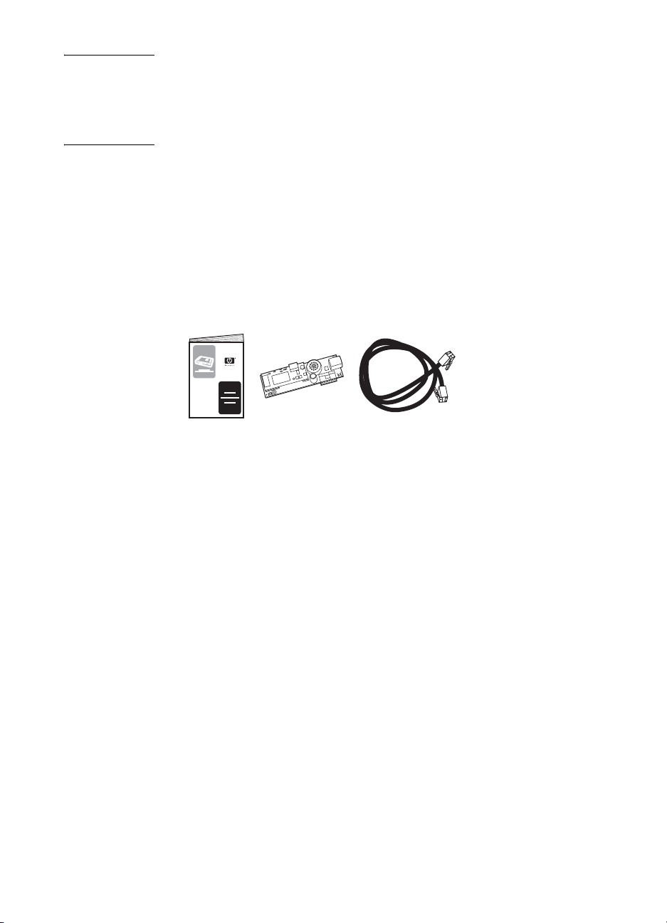
Nota Se l'MFP è stato fornito senza l'accessorio fax installato, sarà
necessario installarlo in base alle istruzioni riportate in questo capitolo.
Se l'MFP è stato f ornito con l'a ccessorio fax installato , sarà ne cessario
collegare il cavo telefonico ed eseguire la configurazione iniziale del
fax, operazioni descritte nel presente capitolo.
Componenti forniti con l'accessorio fax
Insieme all'access or i o fax vengono forniti i seguenti co mponenti:
● Guida per il fax (questo documento)
● Scheda hardware dell'accessorio fax
● Cavo telefonico (i cavi variano a seconda del paese/regione)
Figura 1-1 Componenti dell'accessorio fax analogico HP LaserJet MFP 300
Installazione dell'accessorio fax
In questa sezione viene descritta l'installazione dell'hardware
dell'accessorio fax nell'MFP. Sono descritte le procedure per:
● HP LaserJet 9040/9050mfp
● HP LaserJet 4345mfp
Selezionare la procedura che corrisponde all'MFP utilizzato.
L'accessorio fax analogico HP LaserJet MFP 300 è inoltre supportato
dal modello HP LaserJet 9500mfp, che è dotato di un accessorio fax
preinstallato. Per ulteriori informazioni sull'installazione o sostituzione
dell'acce ssorio fax nel modello HP LaserJet 9500mfp, consultare la
Guida dell'utente HP LaserJet 9500mfp.
2 Capitolo 1 -Impostazione ITWW
 Loading...