

Page 1

HPE PSR650-A & PSR650-D
Power Supplies User Manual
Part number: 5998-1525s
Document version: 6PW103-20160401
5998-1525s
Page 2

© Copyright 2015, 2016 Hewlett Packard Enterprise Development
LP
The information contained herein is subject to change without notice.
The only warranties for Hewlett Packard Enterprise products and
services are set forth in the express warranty statements
accompanying such products and services. Nothing herein should be
construed as constituting an additional warranty. Hewlett Packard
Enterprise shall not be liable for technical or editorial errors or
omissions contained herein.
Confidential computer software. Valid license from Hewlett Packard
Enterprise required for possession, use, or copying. Consistent with
F AR 12.211 and 12.212, Commercial Computer Software, Computer
Software Documentation, and Technical Data for Commercial Item s
are licensed to the U.S. Government under vendor’s standard
commercial license.
Links to third-party websites take you outside the Hewlett Packard
Enterprise website. Hewlett Packard Enterprise has no control over
and is not responsible for information outside the Hewlett Packard
Enterprise website.
Acknowledgments
Intel®, Itanium®, Pentium®, Intel Inside®, and the Intel Inside logo
are trademarks of Intel Corporation in the United States and other
countries.
Microsoft® and Windows® are trademarks of the Microsoft group of
companies.
Adobe® and Acrobat® are trademarks of Adobe Systems
Incorporated.
Java and Oracle are registered trademarks of Oracle and/or its
affiliates.
UNIX® is a registered trademark of The Open Group.
Page 3

i
Contents
Introduction ························································ 1
Schematic Views ········································································ 2
Specifications ············································································· 3
Status LED ················································································· 3
Power supply Installation and Removal ············· 5
Installing and Removing a Power supply ···································· 5
Installing a power supply ······················································· 6
Removing a power supply ····················································· 7
Connecting the power cord ························································· 7
Connecting the AC Power cord ············································· 8
Connecting the DC Power cord ············································· 8
Document conventions and icons ···················· 10
Conventions ·············································································· 10
Network topology icons ···························································· 12
Support and other resources ···························· 14
Accessing Hewlett Packard Enterprise Support ······················· 14
Accessing updates ··································································· 14
Websites ·············································································· 15
Customer self repair ···························································· 16
Remote support ··································································· 17
Documentation feedback ····················································· 17
Page 4

1
Introduction
The PSR650-A (JC492A) is a built-in power supply with AC input and
DC output while the PSR650-D (JC493A) is a built-in po wer supply
with DC input and DC output. These two power supply models can
transfer the input voltage into 12 V or 3.3 V needed by the device.
Table 1 Features of the PSR650-A and PSR650-D power
supplies
Feature Description
Protection
functions
Support input under-voltage protection,
output over-voltage protection, short-circuit
protection, and overheat protection
Hot swap support
Support hot swap while the device is in
operation
1+1 hot backup
support
Support 1 + 1 hot backup and current
sharing
CAUTION:
For a device that supports both AC and DC inputs, you can
choose either of the two types of power supplies as needed, but
do not use different types of power supplies in the same device.
Page 5
2
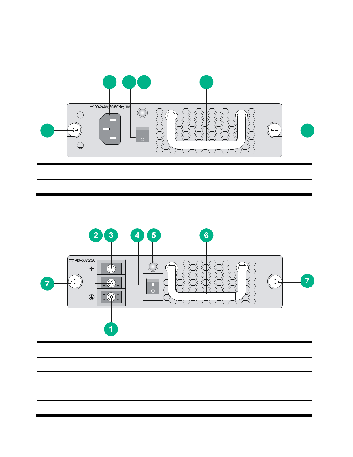
Schematic Views
Figure 1 Schematic view of the PSR650-A
(1) AC power socket (2) Power switch (3) Status LED
(4) Power supply handle (5) Captive screws
Figure 2 Schematic view of the PSR650-D
(1) Grounding point
(2) Negative (–) terminal of DC input
(3) Positive (+) terminal of DC input
(4) Power switch (5) Status LED
(6) Power supply handle (7) Captive screws
5
1 2 3 4
5
Page 6

3
Specifications
Table 2 Technical specifications for the PSR650-A and
PSR650-D
Item Specifications
Rated voltage range
PSR650-A: 100 VAC to 240
VAC; 50 Hz or 60 Hz
PSR650-D: –48 VDC to 60 VDC
Output voltage 12 V or 3.3 V
Max output current
54A (12V)
4A (3.3V)
Max output power 650 W
Dimensions (H × W × D)
40 × 140 × 350 mm (1.57 × 5.51
× 13.78 in.)
Environment
temperature
requirement
Operating
temperature
0°C to 45°C (32°F to 113°F)
Storage
temperature
-40°C to +70°C (-40°F to
+158°F)
Status LED
The PSR650-A and PSR650-D have only one status LED. Table 3
describes its colors and working status.
Page 7

4
Table 3 Description of LEDs on the PSR650-A and PSR650-D
Color/status Meaning Possible causes
Green
The power
supply is
operational.
—
Red
The power
supply is
faulty.
Power alarm (input
under-voltage, output short
circuit, output over-current,
output over-voltage, or
overheat occurred to the power
supply, and the power supply
took a self-protection action).
The power supply fan is faulty.
OFF
The power
input is faulty.
The power switch is off.
The power cord is connected
incorrectly.
CAUTION:
In case of a power alarm (the OUTPUT LED turns red), check
whether output short circuit, output over-current, output
over-voltage, or overheat occurred to the power supply. In the
case of output short circuit, or abnormal temperature, the powe
r
supply will resume normal operation automatically when the
fault is cleared. However, if the power alarm is caused by output
over-voltage, the power supply will get locked up and will not
resume operation automatically. In this case, turn off the power
switch, disconnect the power cord, and then reconnect the
power cord and turn on the power switch.
Do not turn on and off the power switch too frequently. After
turning off the power switch, wait at least 30 seconds before
turning it on again.
Page 8
5
Power supply Installation and
Removal
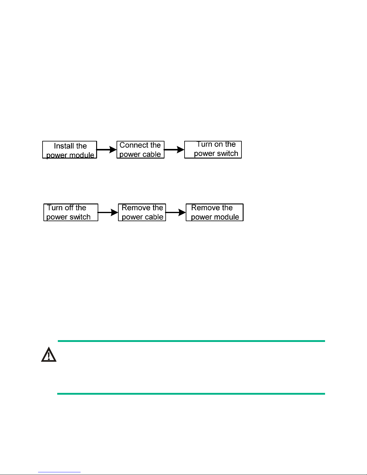
When installing or removing a power supply, be sure to follow the
sequence shown in Figure 3 or
Figure 4.
Figure 3 Flow chart for i nstalling a power supply
Figure 4 Flow chart for removing a power supply
Installing and Removing a Power supply
This section describes how to install and remove a PSR650-A power
supply. You can install and remove a PSR650 -D power supply in a
similar way.
You need to prepare the tools that you need to use to install or
remove power supplies.
WARNING!
When installing or removing a power supply, make sure that the
power switch is in the OFF position and no power cord is
connected to the power supply.
Page 9
6
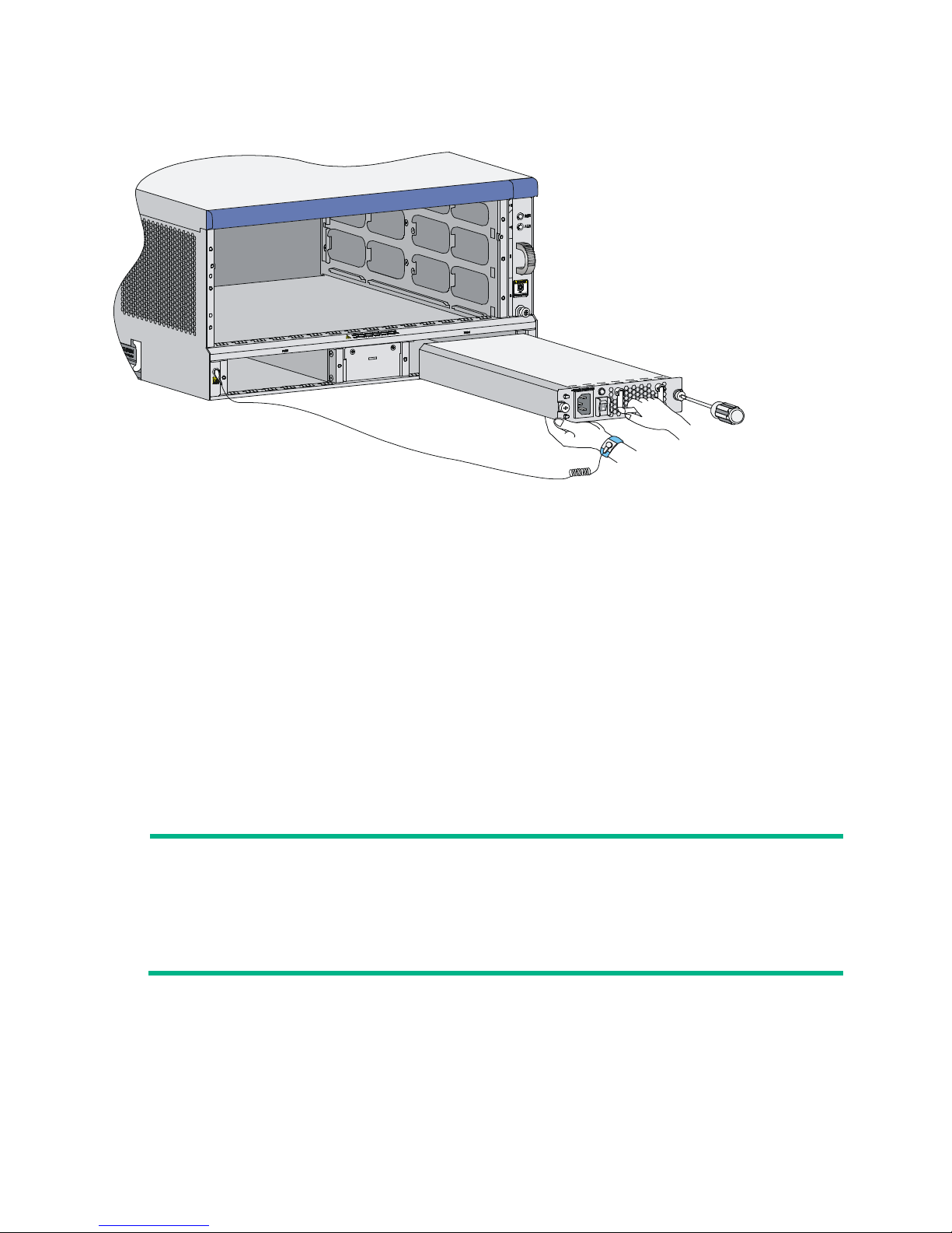
Figure 5 Install/remove a PSR650-A power supply
Installing a power supply
1. Wear an ESD-preventive wrist strap and take a new power
supply out of its package. Check that the input mode of the
power supply is correct.
2. Grasp the handle of the module with one hand and hold the
module bottom with the other. Slide the module slowly along the
guide rails into the chassis until it snaps into the chassis
backplane.
NOTE:
To prevent damage to the power supply and the connection
terminals on the backplane, make sure to pull the module out
first in case of any misalignment, and then push it in again.
3. Tighten the captive screws with a number No. 2 Philips
screwdriver.
Page 10

7
CAUTION:
If the captive screws cannot be tightened, check whether the
power supply is properly installed.
Removing a power supply
Remove a power supply in the opposite way you install it:
1. Wear an ESD-preventive wrist strap and loosen the captive
screws on the power supply.
2. Grasp the handle of the power supply with one hand to pull out a
part of it. Then hold the module bottom with the other hand and
take out the module slowly.
CAUTION:
Since the power supply is heavy, you are recommended to
grasp the power supply handle with one hand and hold the
bottom with the other while pulling out a power supply slowly.
Connecting the power cord
After installing the power supply to the device, you can connect the
power cord. When connecting the power cord, check that:
• The power switch is in the OFF position.
• In the case of a DC power supply, make sure that the power
switch at the other end of the DC power cord is also in the OFF
position to avoid danger.
Page 11
8
Connecting the AC Power cord
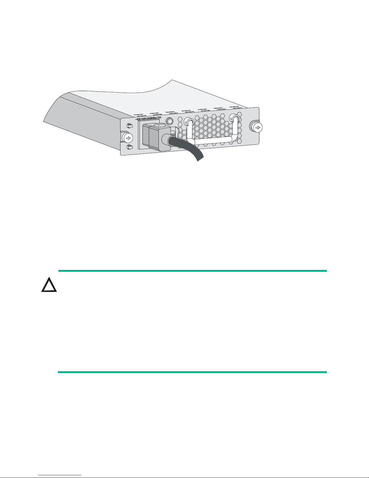
Figure 6 Connect the AC power cord
1. Plug one end of the power cord shipped with the device into the
power socket.
2. Plug the other end into the AC power socket strip of the AC
mains.
Connecting the DC Power cord
CAUTION:
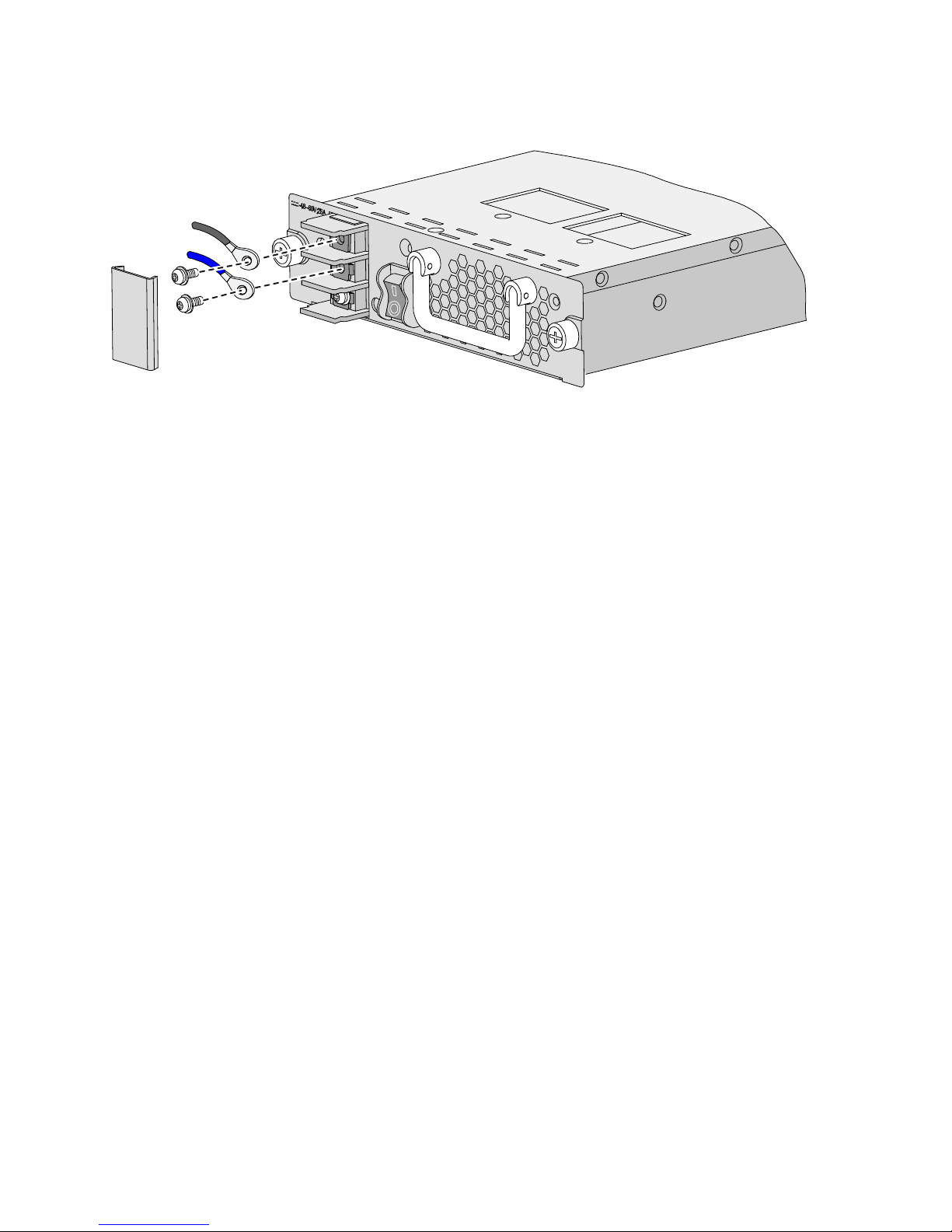
• The power cord color code scheme in Figure 7 is
for
illustration only. The cable delivered for your country or
region might use a different color scheme. When you
connect the power cord, always identify the polarity symbol
on its wires.
• Turn off all power supplies to the device before connecting
the DC power cord.
Page 12
9
Figure 7 Connect the DC power cord
To connect the PSR650-D power supply, proceed as follows:
1. Remove the protection cover from the wiring terminals.
2. Loosen the fastening nut on the wiring terminals with a No. 2
Philips screwdriver.
3. Connect t the wire marked with the negative polarity symbol (–
or L–) to the negative terminal (–) on the power supply and
fasten the screw.
4. Connect the wire marked with the positive polarity symbol (+ or
M/N) to the positive (+) terminal on the power supply and fasten
the screw.
5. Put the protection cover on the wiring terminals.
6. Connect the other ends of the wires to the DC power source
wiring terminals, with the negative wire (– or L–) to the negative
terminal (–) and the positive wire (+ or M/N) to the positive
terminal (+).
Page 13

10
Document conventions and icons
Conventions
This section describes the conventions used in the documentation.
Port numbering in examples
The port numbers in this document are for illustration only and might
be unavailable on your device.
Command conventions
Convention Description
Boldface
Bold text represents commands and keywords
that you enter literally as shown.
Italic
Italic
text represents arguments that you
replace with actual values.
[ ]
Square brackets enclose syntax choices
(keywords or arguments) that are optional.
{ x | y | ... }
Braces enclose a set of required syntax
choices separated by vertical bars, from which
you select one.
[ x | y | ... ]
Square brackets enclose a set of optional
syntax choices separated by vertical bars, from
which you select one or none.
{ x | y | ... } *
Asterisk marked braces enclose a set of
required syntax choices separated by vertical
bars, from which you select at least one.
Page 14

11
Convention Description
[ x | y | ... ] *
Asterisk marked square brackets enclose
optional syntax choices separated by vertical
bars, from which you select one choice,
multiple choices, or none.
&<1-n>
The argument or keyword and argument
combination before the ampersand (&) sign
can be entered 1 to n times.
#
A line that starts with a pound (#) sign is
comments.
GUI conventions
Convention Description
Boldface
Window names, button names, field names,
and menu items are in Boldface. For example,
the New User window appears; click OK.
>
Multi-level menus are separated by angle
brackets. For example, File > Create > Folder.
Symbols
Convention Description
WARNING!
An alert that calls attention to important
information that if not understood or followed
can result in personal injury.
CAUTION:
An alert that calls attention to important
information that if not understood or followed
can result in data loss, data corruption, or
damage to hardware or software.
Page 15
12
Convention Description
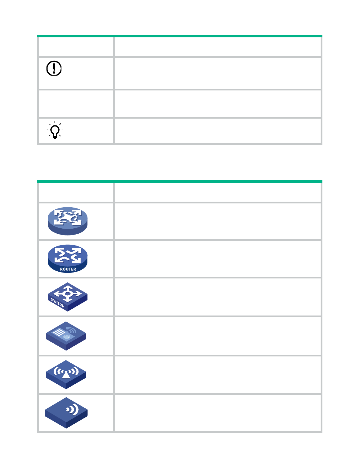
IMPORTANT:
An alert that calls attention to essential
information.
NOTE:
An alert that contains additional or
supplementary information.
TIP:
An alert that provides helpful information.
Network topology icons
Convention Description
Represents a generic network device, such as
a router, switch, or firewall.
Represents a routing-capable device, such as
a router or Layer 3 switch.
Represents a generic switch, such as a Layer 2
or Layer 3 switch, or a router that supports
Layer 2 forwarding and other Layer 2 features.
Represents an access controller, a unified
wired-WLAN module, or the access controller
engine on a unified wired-WLAN switch.
Represents an access point.
Represents a wireless terminator unit.
T
T
Page 16
13
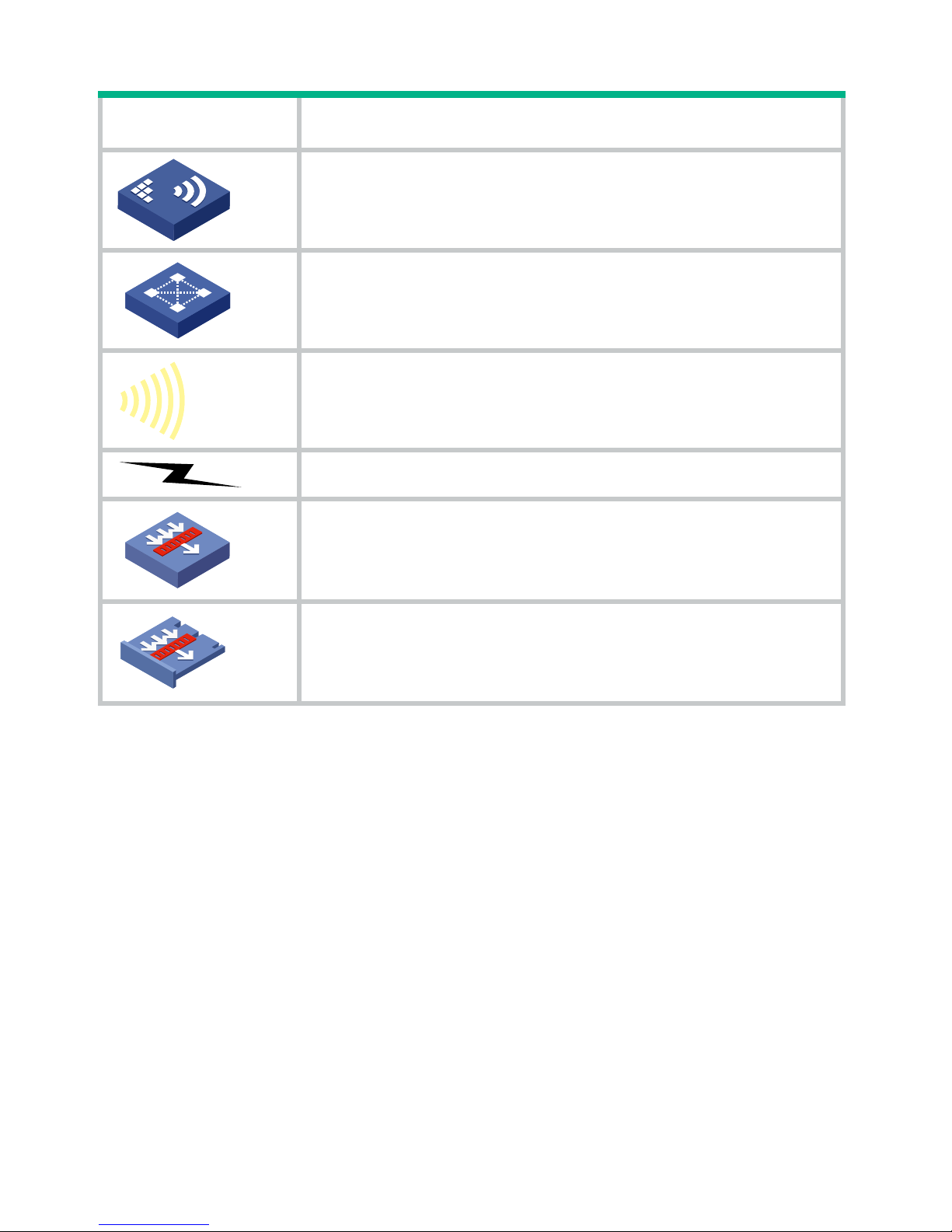
Convention Description
Represents a wireless terminator.
Represents a mesh access point.
Represents omnidirectional signals.
Represents directional signals.
Represents a security product, such as a
firewall, UTM, multiservice security gatew ay, or
load balancing device.
Represents a security card, such as a firewall,
load balancing, NetStream, SSL VPN, IPS, or
ACG card.
T
T
Page 17

14
Support and other resources
Accessing Hewlett Packard Enterprise
Support
• For live assistance, go to the Contact Hewlett Packard
Enterprise Worldwide website:
www.hpe.com/assistance
• To access documentation and support services, go to the
Hewlett Packard Enterprise Support Center website:
www.hpe.com/support/hpesc
Information to collect
• Technical support registration number (if applicable)
• Product name, model or version, and serial number
• Operating system name and version
• Firmware version
• Error messages
• Product-specific reports and logs
• Add-on products or components
• Third-party products or components
Accessing updates
• Some software products provide a mechanism for accessing
software updates through the product interface. Review your
product documentation to identify the recommended software
update method.
Page 18

15
• To download product updates, go to either of the following:
{ Hewlett Packard Enterprise Support Center Get connected
with updates page:
www.hpe.com/support/e-updates
{ Software Depot website:
www.hpe.com/support/softwaredepot
• To view and update your entitlements, and to link your contracts,
Care Packs, and warranties with your profile, go to the Hewlett
Packard Enterprise Support Center More Information on
Access to Support Materials page:
www.hpe.com/support/AccessToSupportMaterials
IMPORTANT:
A
ccess to some updates might require product entitlement when
accessed through the Hewlett Packard Enterprise Support
Center. You must have an HP Passport set up with relevant
entitlements.
Websites
Networking websites:
• Hewlett Packard Enterprise Information Library for Networking
www.hpe.com/networking/resourcefinder
• Hewlett Packard Enterprise Networking website
www.hpe.com/info/networking
• Hewlett Packard Enterprise My Networking website
www.hpe.com/networking/support
• Hewlett Packard Enterprise My Networking Portal
www.hpe.com/networking/mynetworking
Page 19

16
• Hewlett Packard Enterprise Networking Warranty
www.hpe.com/networking/warranty
General websites:
• Hewlett Packard Enterprise Information Library
www.hpe.com/info/enterprise/docs
• Hewlett Packard Enterprise Support Center
www.hpe.com/support/hpesc
• Hewlett Packard Enterprise Support Services Central
ssc.hpe.com/portal/site/ssc/
• Contact Hewlett Packard Enterprise Worldwide
www.hpe.com/assistance
• Subscription Service/Support Alerts
www.hpe.com/support/e-updates
• Software Depot
www.hpe.com/support/softwaredepot
• Customer Self Repair (not applicable to all devices)
www.hpe.com/support/selfrepair
• Insight Remote Support (not applicable to all devices)
www.hpe.com/info/insightremotesupport/docs
Customer self repair
Hewlett Packard Enterprise customer self repair (CSR) programs
allow you to repair your product. If a CSR part needs to be replaced,
it will be shipped directly to you so that you can install it at your
convenience. Some parts do not qualify for CSR. Your Hewlett
Packard Enterprise authorized service provider will determine
whether a repair can be accomplished by CSR.
Page 20

17
For more information about CSR, contact your local service provider
or go to the CSR website:
www.hpe.com/support/selfrepair
Remote support
Remote support is available with supported devices as part of your
warranty, Care Pack Service, or contractual support agreement. It
provides intelligent event diagnosis, and automatic, secure
submission of hardware event notifications to Hewlett Packard
Enterprise, which will initiate a fast and accurate resolution based on
your product’s service level. Hewlett Packard Enterprise strongly
recommends that you register your device for remote support.
For more information and device support details, go to t he following
website:
www.hpe.com/info/insightremotesupport/docs
Documentation feedback
Hewlett Packard Enterprise is committed to providing documentation
that meets your needs. To help us improve the documentation, send
any errors, suggestions, or comments to Documentation Feedback
([email protected]
). When submitting your feedback, include
the document title, part number, edition, and publication date located
on the front cover of the document. For online help content, include
the product name, product version, help edition, and publication date
located on the legal notices page.
 Loading...