

Page 1

Hardware Reference Guide
HP ProOne 600 G4 21.5-inch All-in-One Business PC
HP ProOne 400 G4 23.8-inch All-in-One Business PC
HP ProOne 400 G4 20-inch All-in-One Business PC
Page 2

© Copyright 2018 HP Development Company,
L.P.
Windows is either a trademark or registered
trademark of Microsoft Corporation in the
United States and/or other countries.
The information contained herein is subject to
change without notice. The only warranties for
HP products and services are set forth in the
express warranty statements accompanying
such products and services. Nothing herein
should be construed as constituting an
additional warranty. HP shall not be liable for
technical or editorial errors or omissions
contained herein.
This document contains proprietary
information that is protected by copyright. No
part of this document may be photocopied,
reproduced, or translated to another language
without the prior written consent of HP
Development Company.
First Edition: June 2018
Document part number: L20661-001
Page 3

About This Book
This guide provides basic information for upgrading this computer model.
WARNING! Text set o in this manner indicates that failure to follow directions could result in bodily harm or
loss of life.
CAUTION: Text set o in this manner indicates that failure to follow directions could result in damage to
equipment or loss of information.
NOTE: Text set o in this manner provides important supplemental information.
iii
Page 4

iv About This Book
Page 5

Table of contents
1 Product features ........................................................................................................................................... 1
Overview ................................................................................................................................................................ 1
HP ProOne 600 and HP ProOne 400 23.8-inch components ................................................................................ 2
Front components ............................................................................................................................... 2
Side components ................................................................................................................................. 3
Rear components ................................................................................................................................ 4
Bottom components ............................................................................................................................ 4
HP ProOne 400 20-inch components .................................................................................................................... 5
Front components ............................................................................................................................... 5
Side components ................................................................................................................................. 5
Rear components ................................................................................................................................ 6
Bottom components ............................................................................................................................ 6
Keyboard features ................................................................................................................................................. 7
Labels ..................................................................................................................................................................... 8
2 Setup ............................................................................................................................................................ 9
Overview ................................................................................................................................................................ 9
Attaching and removing a stand ............................................................................................................................ 9
Attaching and removing a xed-height stand .................................................................................... 9
Attaching a xed-height stand ......................................................................................... 9
Removing a xed-height stand ...................................................................................... 10
Attaching and removing an adjustable height stand ........................................................................ 10
Attaching an adjustable height stand ............................................................................ 10
Removing an adjustable height stand ............................................................................ 11
Attaching the computer to a mounting xture ................................................................................................... 12
Connecting and disconnecting cables ................................................................................................................. 13
Connecting cables ............................................................................................................................. 13
Connecting a display ......................................................................................................................... 13
Disconnecting cables ......................................................................................................................... 14
Removing and installing the rear port cover ....................................................................................................... 14
Removing the rear port cover ........................................................................................................... 14
Installing the rear port cover ............................................................................................................ 15
Positioning the computer .................................................................................................................................... 15
Adjusting a xed-height stand .......................................................................................................... 15
Adjusting an adjustable height stand ............................................................................................... 16
Installing a security cable .................................................................................................................................... 17
v
Page 6

Connecting and disconnecting power ................................................................................................................. 17
Connecting power .............................................................................................................................. 17
Disconnecting power ......................................................................................................................... 18
Webcam ............................................................................................................................................................... 18
Webcam operation ............................................................................................................................ 18
Setting up Windows Hello ................................................................................................................. 18
Synchronizing the optional wireless keyboard and mouse ................................................................................ 19
3 Hardware repair and upgrade ....................................................................................................................... 21
Warnings and cautions ........................................................................................................................................ 21
Additional information ........................................................................................................................................ 21
Removing batteries from the optional wireless keyboard or mouse ................................................................. 22
Locating internal components ............................................................................................................................ 23
Removing and installing memory ....................................................................................................................... 23
Memory module specications ......................................................................................................... 23
Populating memory module slots .................................................................................................... 24
Installing memory modules .............................................................................................................. 25
Replacing the RTC Battery ................................................................................................................................... 26
Replacing drives ................................................................................................................................................... 27
Replacing a hard drive ....................................................................................................................... 27
Removing a hard drive .................................................................................................... 27
Installing a 2.5 inch hard disk drive ................................................................................ 27
Installing the optical disc drive ......................................................................................................... 28
Appendix A Electrostatic discharge .................................................................................................................. 29
Preventing electrostatic damage ........................................................................................................................ 29
Grounding methods ............................................................................................................................................. 29
Appendix B Computer operating guidelines, routine care, and shipping preparation ............................................ 30
Computer operating guidelines and routine care ............................................................................................... 30
Optical disc drive precautions ............................................................................................................................. 31
Shipping preparation ........................................................................................................................................... 31
Appendix C Accessibility ................................................................................................................................. 32
Supported assistive technologies ....................................................................................................................... 32
Contacting support .............................................................................................................................................. 32
Index ............................................................................................................................................................. 33
vi
Page 7
1 Product features
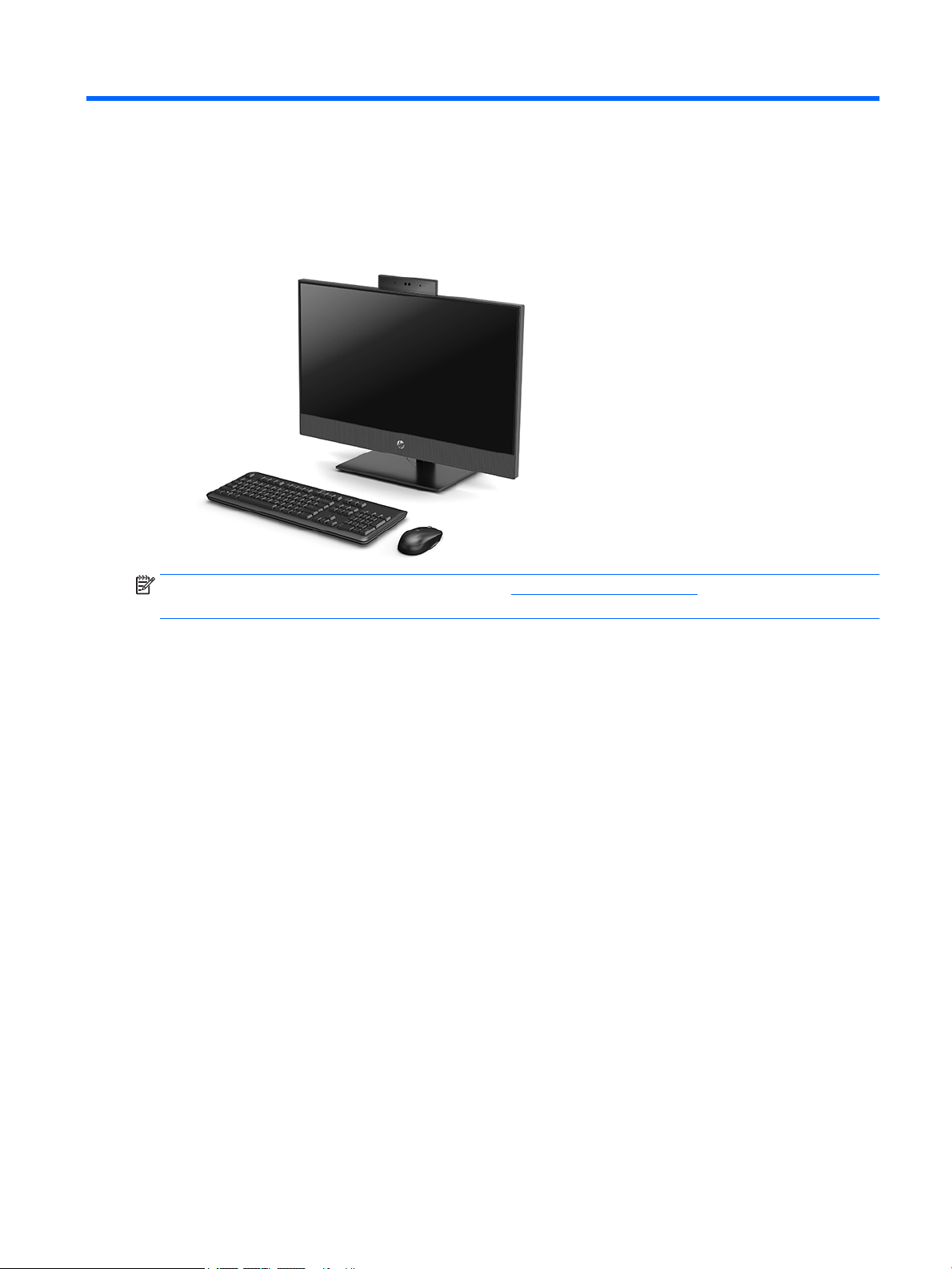
Overview
NOTE: For the latest manuals on this product, go to http://www.hp.com/support. Select Find your product,
and then follow the on-screen instructions.
Overview 1
Page 8
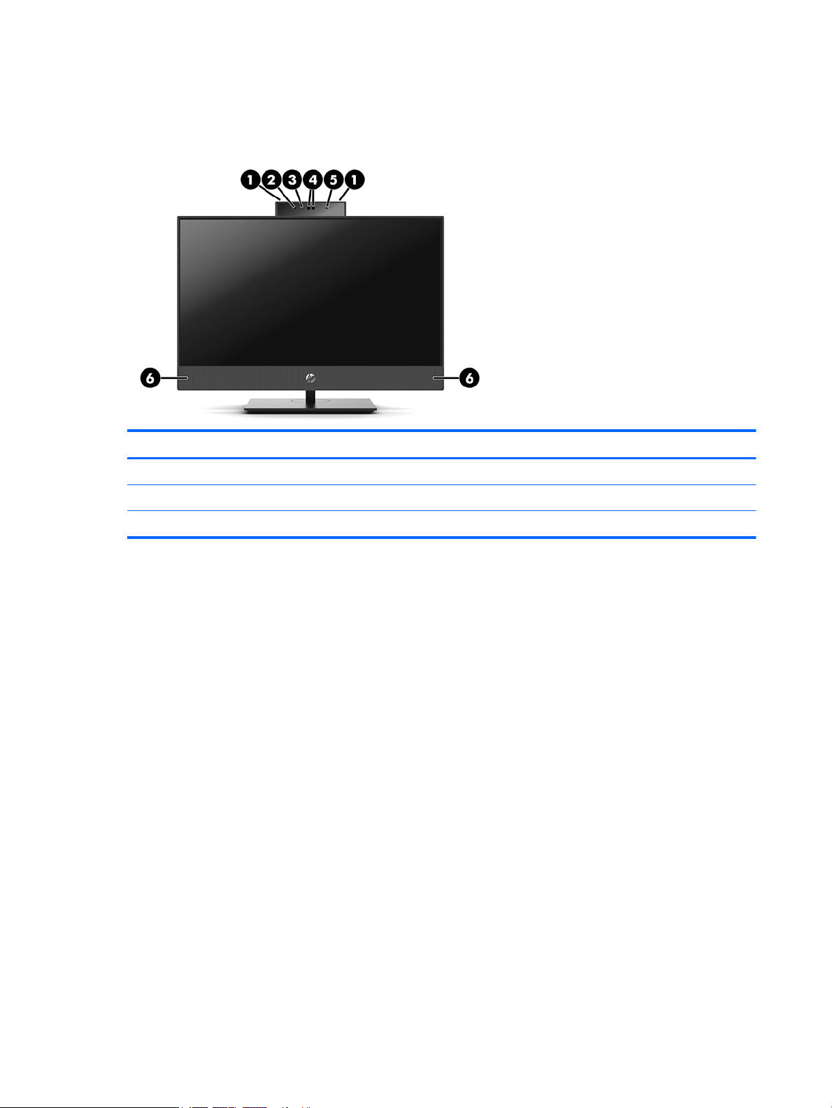
HP ProOne 600 and HP ProOne 400 23.8-inch components
Front components
Component Component
1 Webcam microphones (2) (optional) 4 Webcam/IR lens (optional)
2 IR LED (optional) 5 IR LED (optional)
3 Webcam LED (optional) 6 Speakers (2) (optional)
2 Chapter 1 Product features
Page 9
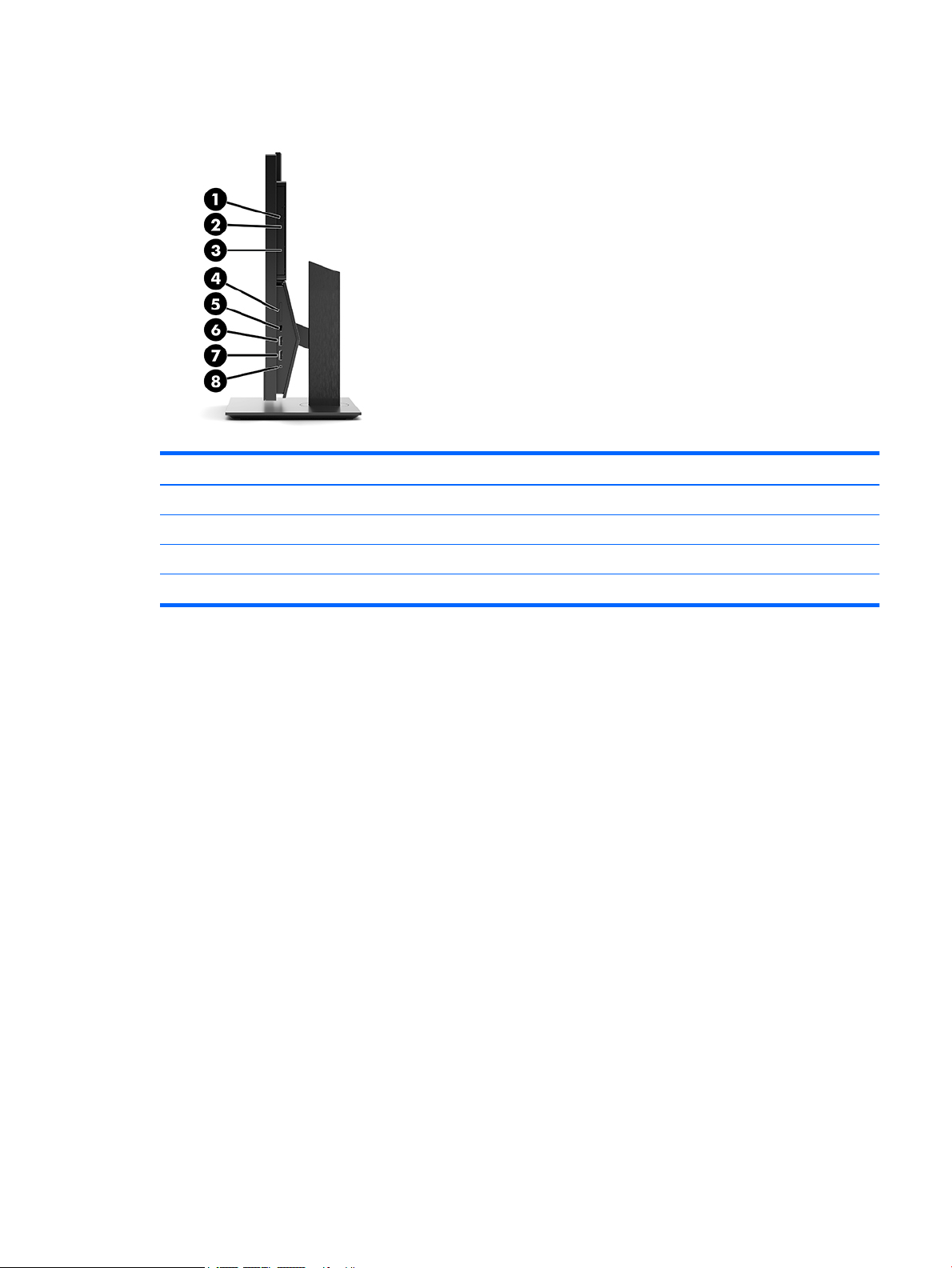
Side components
Component Component
1 Optical disc drive (optional) 5 USB 3.1 Type-C port
2 Optical disc drive light (optional) 6 USB 3.1 Type-A (charging) port
3 Optical disc drive eject button (optional) 7 USB 3.1 Type-A port
4 SD card reader (optional) 8 Audio-out (headphone)/Audio-in (microphone) combo jack
HP ProOne 600 and HP ProOne 400 23.8-inch components 3
Page 10
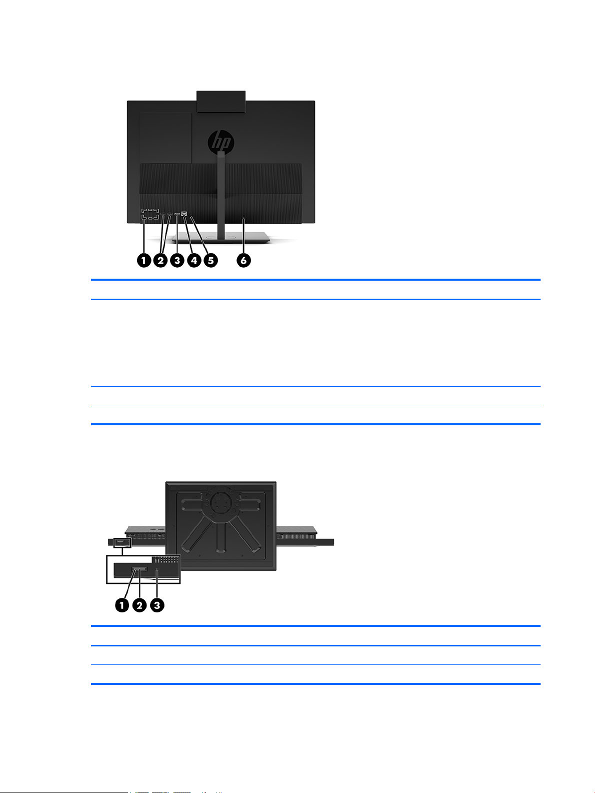
Rear components
Component Component
1 DisplayPort port (optional)
– or –
HDMI port (optional)
– or –
Serial port (optional)
2 USB 3.1 Type-A ports (2) 5 Power connector
3 DisplayPort port 6 Security cable slot
Bottom components
4 RJ-45 (network) jack
Component Component
1 Power button 3 Hard drive activity light
2 Power light
4 Chapter 1 Product features
Page 11
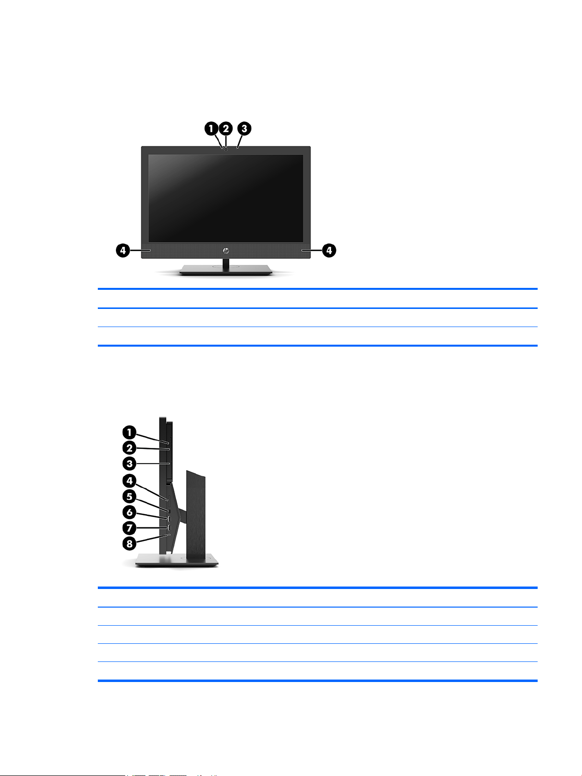
HP ProOne 400 20-inch components
Front components
Component Component
1 Webcam LED 3 Webcam microphone
2 Webcam lens 4 Speakers (2) (optional)
Side components
Component Component
1 Optical disc drive (optional) 5 USB 3.1 Type-C port
2 Optical disc drive light (optional) 6 USB 3.1 Type-A (charging) port
3 Optical disc drive eject button (optional) 7 USB 3.1 Type-A port
4 SD card reader (optional) 8 Audio-out (headphone)/Audio-in (microphone) combo jack
HP ProOne 400 20-inch components 5
Page 12
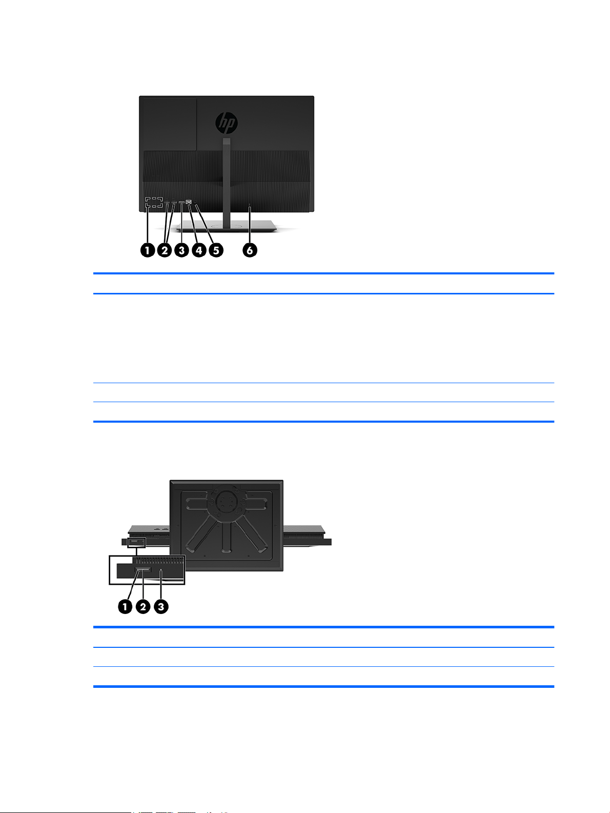
Rear components
Component Component
1 DisplayPort port (optional)
– or –
HDMI port (optional)
– or –
Serial port (optional)
2 USB 3.1 Type-A ports (2) 5 Power connector
3 DisplayPort port 6 Security cable slot
Bottom components
4 RJ-45 (network) jack
Component Component
1 Power button 3 Hard drive activity light
2 Power light
6 Chapter 1 Product features
Page 13
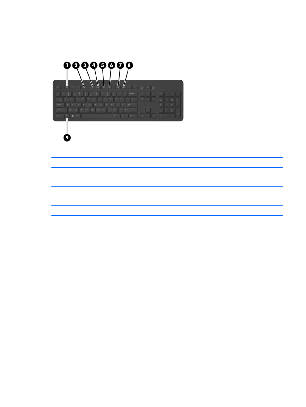
Keyboard features
Your keyboard and mouse may be dierent.
Component Component
1 Sleep 6 Mute Volume
2 Fast Reverse 7 Decrease Volume
3 Play/Pause 8 Increase Volume
4 Stop 9 Function
5 Fast Forward
Keyboard features 7
Page 14
Labels
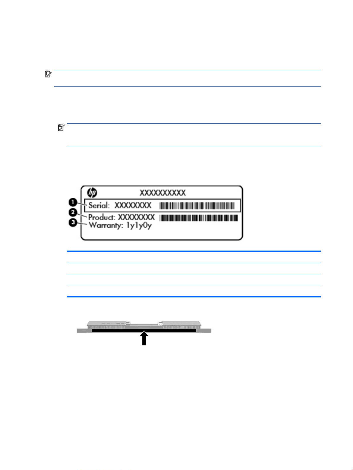
The labels axed to the computer provide information you may need when you troubleshoot system
problems or travel internationally with the computer.
IMPORTANT: All labels described in this section will be located under the stand or axed to the bottom of
the computer.
1. Microsoft® Certicate of Authenticity label (select models only prior to Windows 8)—Contains the
Windows Product Key. You may need the Product Key to update or troubleshoot the operating system.
HP platforms preinstalled with Windows 8 or Windows 8.1 do not have the physical label, but have a
Digital Product Key electronically installed.
NOTE: This Digital Product Key is automatically recognized and activated by Microsoft Operating
Systems on a reinstall of the Windows 8 or Windows 8.1 operating system with HP-approved recovery
methods.
2. Service label—Provides important information to identify your computer. When contacting support, you
will probably be asked for the serial number, and possibly for the product number or the model number.
Locate these numbers before you contact support.
Component
(1) Serial number
(2) Product number
(3) Warranty period
3. Serial number label
8 Chapter 1 Product features
Page 15

2 Setup
Overview
Set up the computer in the following order:
● Attach a stand. See Attaching and removing a stand on page 9.
Or
Attach the computer to a mounting xture. See Attaching the computer to a mounting xture
on page 12.
● Connect the cables for peripherals and power. See Connecting and disconnecting cables on page 13.
● Connect an additional display, if desired. See Connecting a display on page 13.
● Install and secure the rear port cover. See Installing the rear port cover on page 15.
● Select a comfortable computer position and viewing angle. See Positioning the computer on page 15.
● Install a security cable for security. See Installing a security cable on page 17.
● Turn on the power. See Connecting power on page 17.
● The mouse and keyboard are synchronized at the factory. Should you ever need to synchronize the
mouse and keyboard again, see Synchronizing the optional wireless keyboard and mouse on page 19.
Attaching and removing a stand
Two stands are available for the computer:
●
Attaching and removing a xed-height stand
●
Attaching and removing an adjustable height stand
Attaching and removing a xed-height stand
Attaching a xed-height stand
To install the stand:
1. Place the computer facedown on a soft at surface. HP recommends that you set down a blanket, towel,
or other soft cloth to protect the bezel and screen surface from scratches or other damage.
2. Engage the hooks in the top of the stand in the two large holes in the upper part of the back of the
computer (1).
Overview 9
Page 16
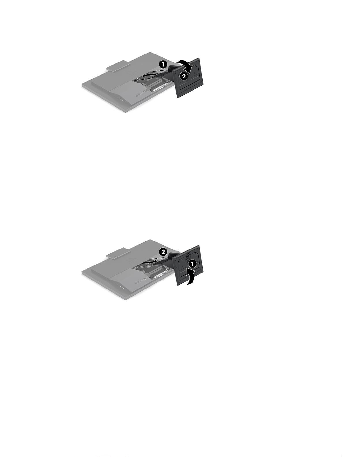
3. Rotate the stand down until it clicks into place (2).
Removing a xed-height stand
To remove the stand:
1. Remove all removable media, such as optical discs or USB ash drives, from the computer.
2. Turn o the computer properly through the operating system, then turn o any external devices.
3. Disconnect the AC power cord from the AC outlet and disconnect any external devices.
4. Place the computer facedown on a soft at surface. HP recommends that you set down a blanket, towel,
or other soft cloth to protect the bezel and screen surface from scratches or other damage.
5. Press the stand release latch.
6. Rotate the stand away from the computer (1).
7. Slide the stand hooks out of the computer (2).
Attaching and removing an adjustable height stand
Attaching an adjustable height stand
To install the stand:
1. Place the computer facedown on a soft at surface. HP recommends that you set down a blanket, towel,
or other soft cloth to protect the bezel and screen surface from scratches or other damage.
2. Engage the hooks in the top of the stand in the two large holes in the upper part of the back of the
computer (1).
10 Chapter 2 Setup
Page 17
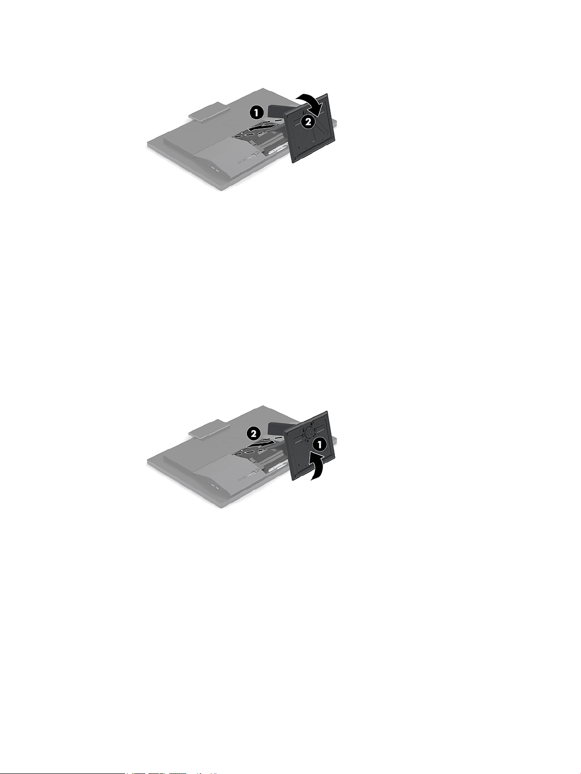
3. Rotate the stand down until it clicks into place (2).
Removing an adjustable height stand
To remove the stand:
1. Remove all removable media, such as optical discs or USB ash drives, from the computer.
2. Turn o the computer properly through the operating system, then turn o any external devices.
3. Disconnect the AC power cord from the AC outlet and disconnect any external devices.
4. Place the computer facedown on a soft at surface. HP recommends that you set down a blanket, towel,
or other soft cloth to protect the bezel and screen surface from scratches or other damage.
5. Press the stand release latch.
6. Rotate the stand away from the computer (1).
7. Slide the stand hooks out of the computer (2).
Attaching and removing a stand 11
Page 18
Attaching the computer to a mounting xture
The computer can be attached to a wall, swing arm, or other mounting xture.
NOTE: This apparatus is intended to be supported by UL or CSA Listed wall mount bracket.
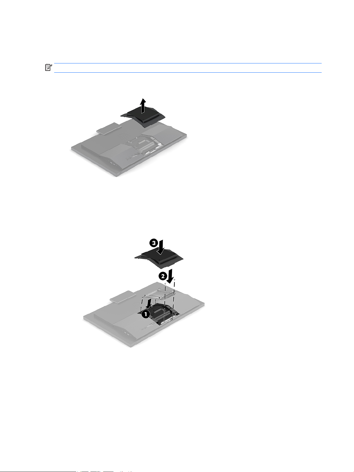
1. Insert the VESA mount bracket in the two large holes in the upper part of the back of the computer (1),
and then rotate it down.
2. Secure the VESA mount bracket with two screws (2).
3. Press the supplied VESA trim plate onto the VESA opening until it snaps into place (3).
12 Chapter 2 Setup
Page 19
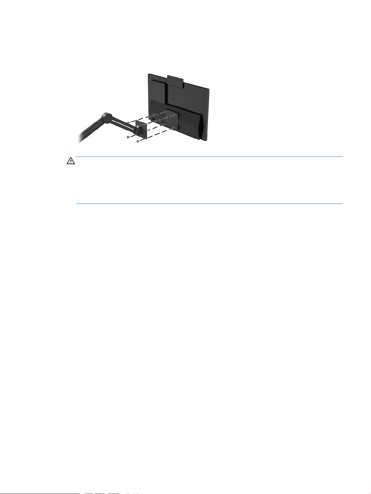
4. To attach the computer to a swing arm (sold separately), insert the four 20 mm screws that are supplied
with the computer through the holes on the swing arm plate and into the mounting holes on the
computer.
CAUTION: This computer supports the VESA industry standard 100 mm mounting holes. To attach a
third-party mounting solution to the computer, four 4 mm, 0.7 pitch, and 20 mm long screws are
required. These screws are supplied with the computer. Longer screws must not be used because they
may damage the computer. It is important to verify that the manufacturer’s mounting solution is
compliant with the VESA standard and is rated to support the weight of the computer. For best
performance, it is important to use the power and other cables provided with the computer.
To attach the computer to other mounting xtures, follow the instructions included with the mounting
xture to ensure that the computer is safely attached.
Connecting and disconnecting cables
Connecting cables
1. Connect the peripheral cables to the appropriate ports.
2. Connect the power cord to the power connector on the rear of the computer.
Connecting a display
The ports on the rear of the computer allow you to connect up to two displays to the computer.
If you are adding a display that has a DisplayPort port, then no video adapter is required. If you are adding a
display that does not have a DisplayPort port, you can purchase a video adaptor from HP for your
conguration.
DisplayPort adapters and video cables are purchased separately. HP oers the following adapters:
● DisplayPort to VGA adapter
● DisplayPort to DVI adapter
To connect a display:
1. Turn o power to the computer and to the display that you are connecting to the computer.
2. If your display has a DisplayPort connector, connect a DisplayPort cable directly between the
DisplayPort connector on the rear of the computer and the DisplayPort connector on the display.
Connecting and disconnecting cables 13
Page 20
3. If your display does not have a DisplayPort connector, connect a DisplayPort video adapter to the
DisplayPort connector of the computer. Then connect a cable (VGA or DVI, depending on your
application) between the adapter and a display.
4. Turn on power to the computer and the display.
NOTE: Use the graphics card software or the Windows Display Settings to congure the display as a
mirrored image of the computer display or an extension of the computer display.
Disconnecting cables
1. You may need to remove the security cable, if one is installed on the rear of the computer.
2. Disconnect the cables from the ports.
Removing and installing the rear port cover
Removing the rear port cover
1. Place the computer facedown on a soft at surface. HP recommends that you set down a blanket, towel,
or other soft cloth to protect the bezel and screen surface from scratches or other damage.
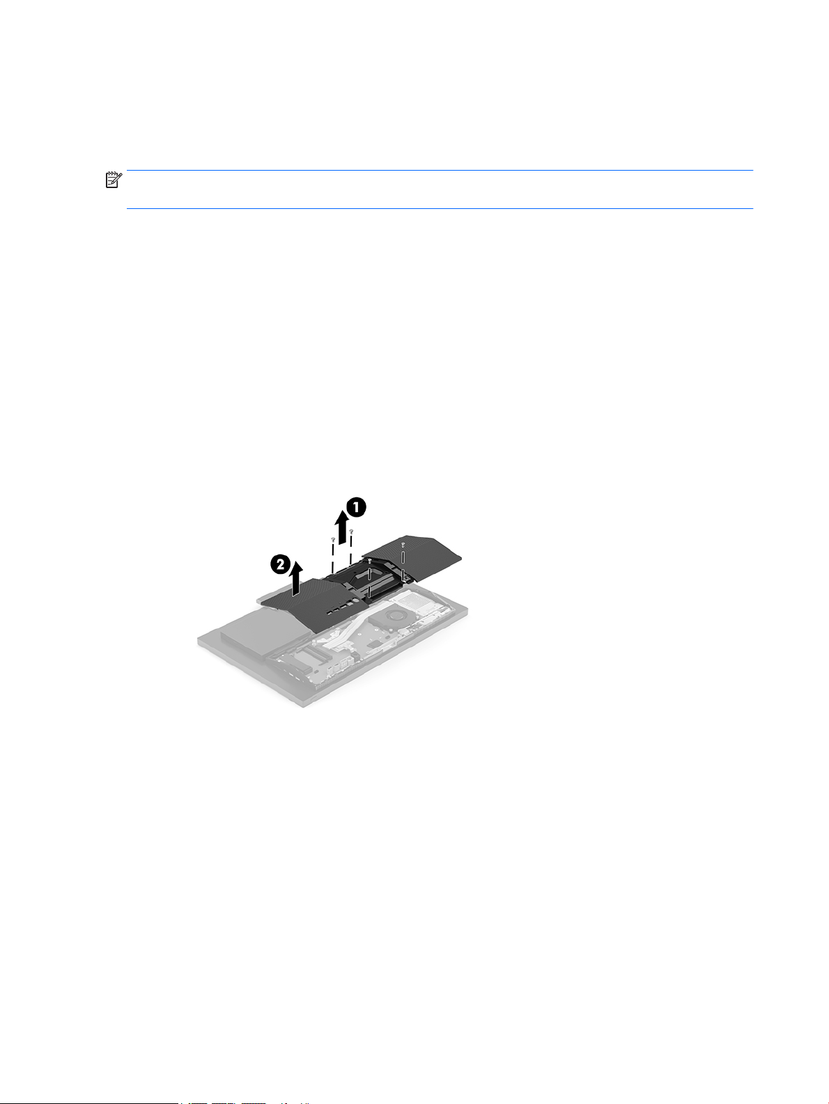
2. Remove the four screws securing the back cover (1), and then lift the back cover from any cavity to
remove it from the computer (2).
14 Chapter 2 Setup
Page 21
Installing the rear port cover
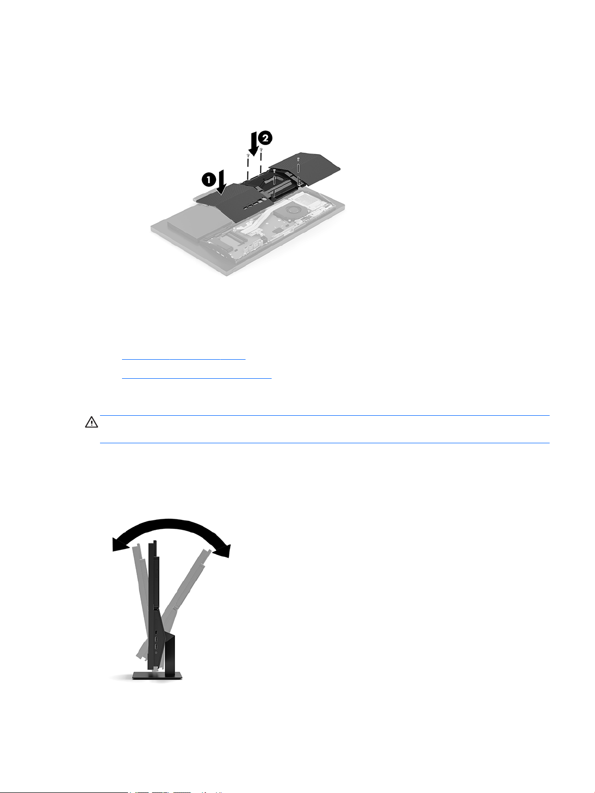
▲ Align the rear port cover with the computer, press all tabs on the panel into place (1), and then secure it
with four screws (2).
Positioning the computer
This computer may ship with a xed-height stand or an adjustable height stand.
●
Adjusting a xed-height stand
●
Adjusting an adjustable height stand
Adjusting a xed-height stand
CAUTION: Use caution when reclining a computer if a cable lock is installed. The cable or the lock may
interfere with the rotation or the angle of recline.
This stand allows you to tilt the computer from -5° to 20° from the desktop.
To tilt the computer:
▲ Grasp both top and bottom of the computer and adjust to the appropriate tilt.
Positioning the computer 15
Page 22
Adjusting an adjustable height stand
CAUTION: Use caution when reclining a computer if a cable lock is installed. The cable or the lock may
interfere with the angle of recline.
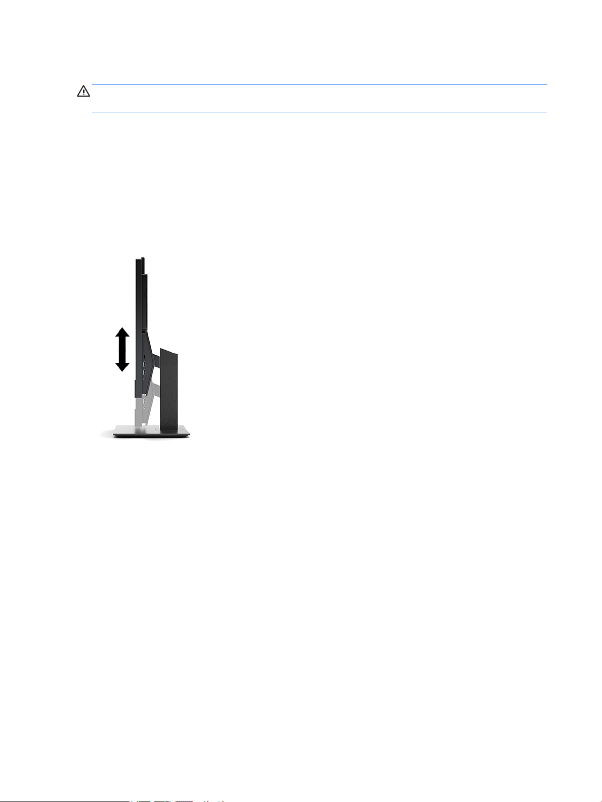
This stand allows you to:
● Tilt the computer from –5° to 20° from the desktop
● Adjust the computer height within a range of 110 mm (4.3 in)
● Swivel the computer up to 45° to either side
To tilt the computer, grasp the top and bottom of the computer and adjust to the appropriate tilt.
To change the height of the computer, grasp both sides of the computer and lift or lower to the appropriate
height.
16 Chapter 2 Setup
Page 23
Installing a security cable
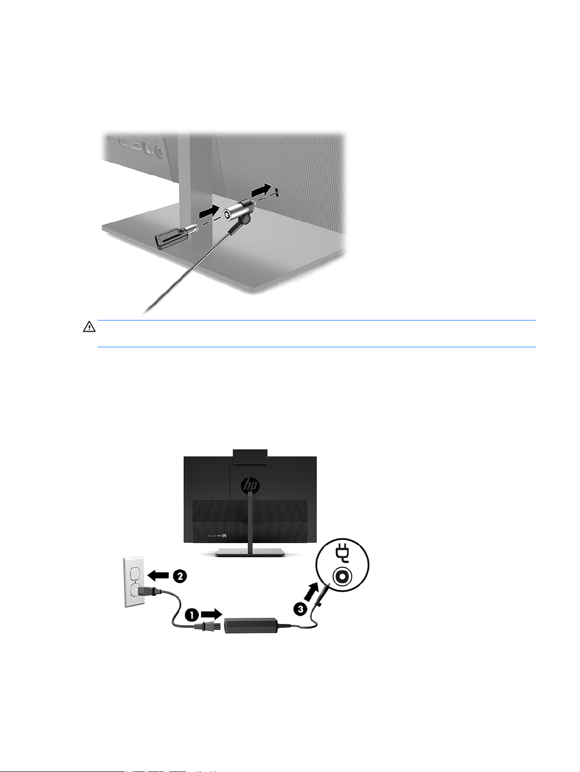
A security cable is a key lock device that has a wire cable attached. You attach one end of the cable to your
desk (or other stationary object) and the other end of the cable to the security cable slot on the computer.
Secure the security cable lock with the key.
CAUTION: Use caution when adjusting the tilt, swivel, or height of the computer if a security cable is
installed. The cable or the lock may interfere with the adjustment.
Connecting and disconnecting power
Connecting power
1. Connect one end of the power cord to the AC adapter (1) and the other end to a grounded AC outlet (2),
and then connect the AC adapter to the computer (3).
2. Press the power button on the side of the computer to turn it on.
Installing a security cable 17
Page 24

Disconnecting power
1. Remove all removable media, such as optical discs or USB ash drives, from the computer.
2. Turn o the computer properly through the operating system, then turn o any external devices.
3. Disconnect the power cord from the AC outlet and disconnect any external devices.
Webcam
With Skype for Business installed on your external source device, you can use the webcam on the monitor in
the following ways:
● Stream online video conferences
● Send and receive instant messages
● Schedule meetings
● Maintain security over conversations
Webcam operation
▲ On the HP ProOne 600 or HP ProOne 23.8-inch computer, raise the webcam to unlock it.
– or –
On the HP ProOne 400 20-inch, slide the webcam shutter to the right to open the webcam.
▲ On the HP ProOne 600 or HP ProOne 23.8-inch computer, press the webcam down until it locks to close
it.
– or –
On the HP ProOne 400 20-inch, slide the webcam shutter to the left to close the webcam.
Setting up Windows Hello
If the Windows 10 operating system is installed on your computer, follow these steps to set up Windows Hello
facial recognition:
1. Select the Start button, select Settings, select Accounts, and then select Sign-in options.
2. Under Windows Hello, follow the on-screen instructions to add both a password and a 4-digit PIN. Then
enroll your ngerprint or facial ID.
18 Chapter 2 Setup
Page 25
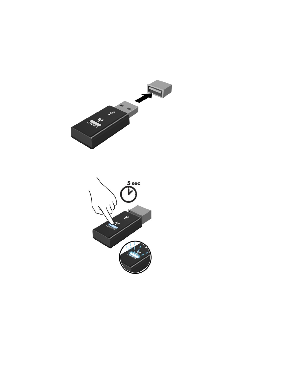
Synchronizing the optional wireless keyboard and mouse
The wireless keyboard and mouse are optional components. The mouse and keyboard are synchronized at the
factory. If they do not work, remove and replace the batteries. If the mouse and keyboard are still not
synchronized, then follow this procedure to manually re-synchronize the pair.
1.
2.
Synchronizing the optional wireless keyboard and mouse 19
Page 26
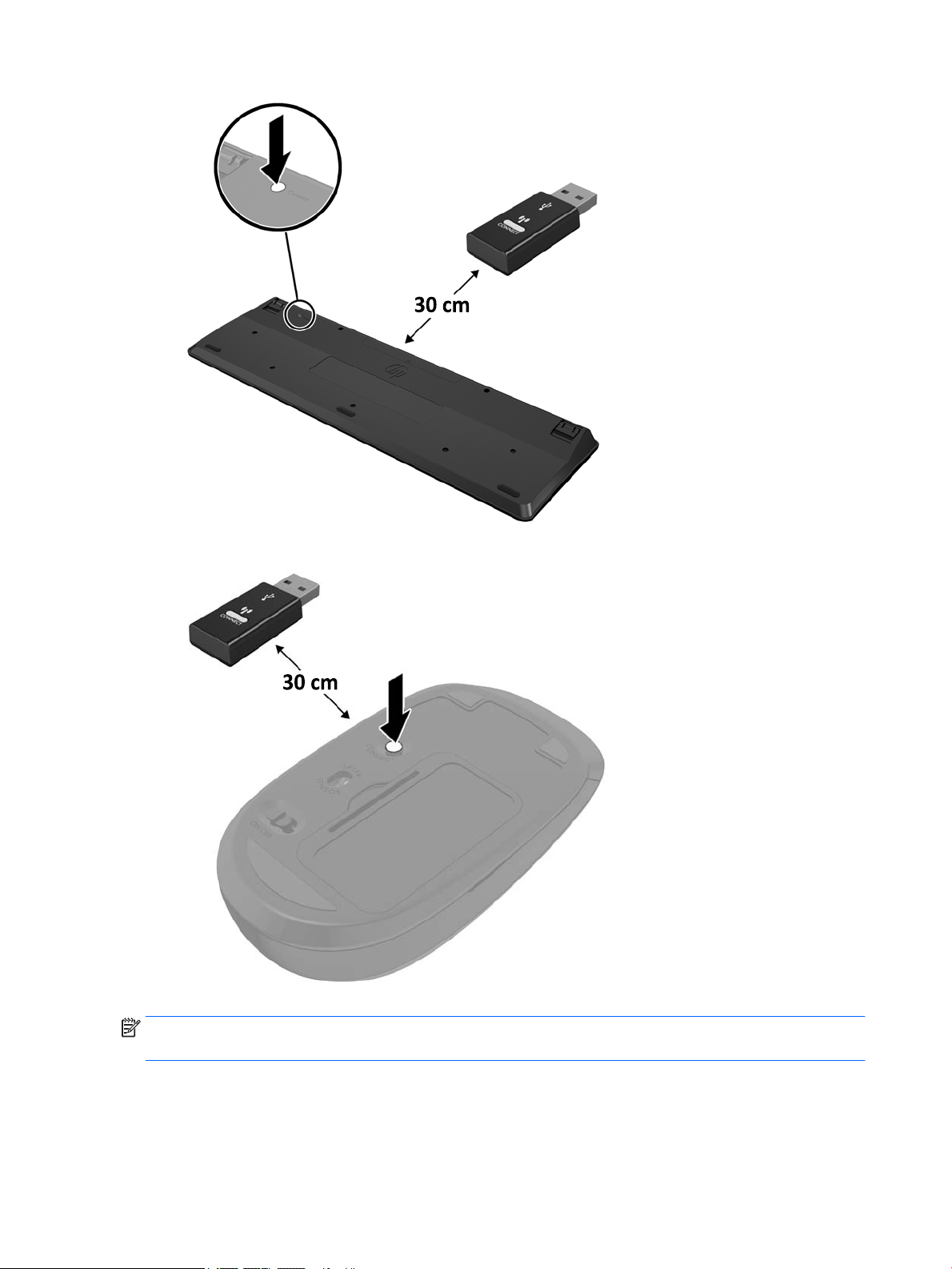
3.
4.
NOTE: If the mouse and keyboard still do not work, then remove and replace the batteries. If the mouse and
keyboard are still not synchronized, then synchronize the keyboard and mouse again.
20 Chapter 2 Setup
Page 27

3 Hardware repair and upgrade
Warnings and cautions
Before performing upgrades be sure to carefully read all of the applicable instructions, cautions, and
warnings in this guide.
WARNING! To reduce the risk of personal injury from electrical shock, hot surfaces, or re:
Disconnect the power cord from the AC outlet before removing the enclosure. Energized parts are inside.
Allow the internal system components to cool before you touch them.
Replace and secure the enclosure before restoring power to the equipment.
Do not connect telecommunications or telephone connectors to the network interface controller (NIC)
receptacles.
Do not disable the power cord grounding plug. The grounding plug is an important safety feature.
Plug the power cord in a grounded (earthed) AC outlet that is easily accessible at all times.
For your safety, do not place anything on power cords or cables. Arrange them so that no one may
accidentally step on or trip over them. Do not pull on a cord or cable. When unplugging from the AC outlet,
grasp the cord by the plug.
To reduce the risk of serious injury, read the Safety & Comfort Guide. It describes proper workstation setup
and provides guidelines for posture and work habits that increase your comfort and decrease your risk of
injury. It also provides electrical and mechanical safety information. This guide is located on the web at
http://www.hp.com/ergo.
CAUTION: Static electricity can damage the electrical components of the computer or optional equipment.
Before beginning these procedures, ensure that you are discharged of static electricity by briey touching a
grounded metal object. See Electrostatic discharge on page 29 for more information.
When the computer is plugged into an AC power source, voltage is always applied to the system board. You
must disconnect the power cord from the power source before opening the computer to prevent damage to
internal components.
Additional information
For more information on removing and replacing hardware components, the Computer Setup utility, and
troubleshooting, refer to the Maintenance and Service Guide (available in English only) for your computer
model at http://www.hp.com.
Warnings and cautions 21
Page 28
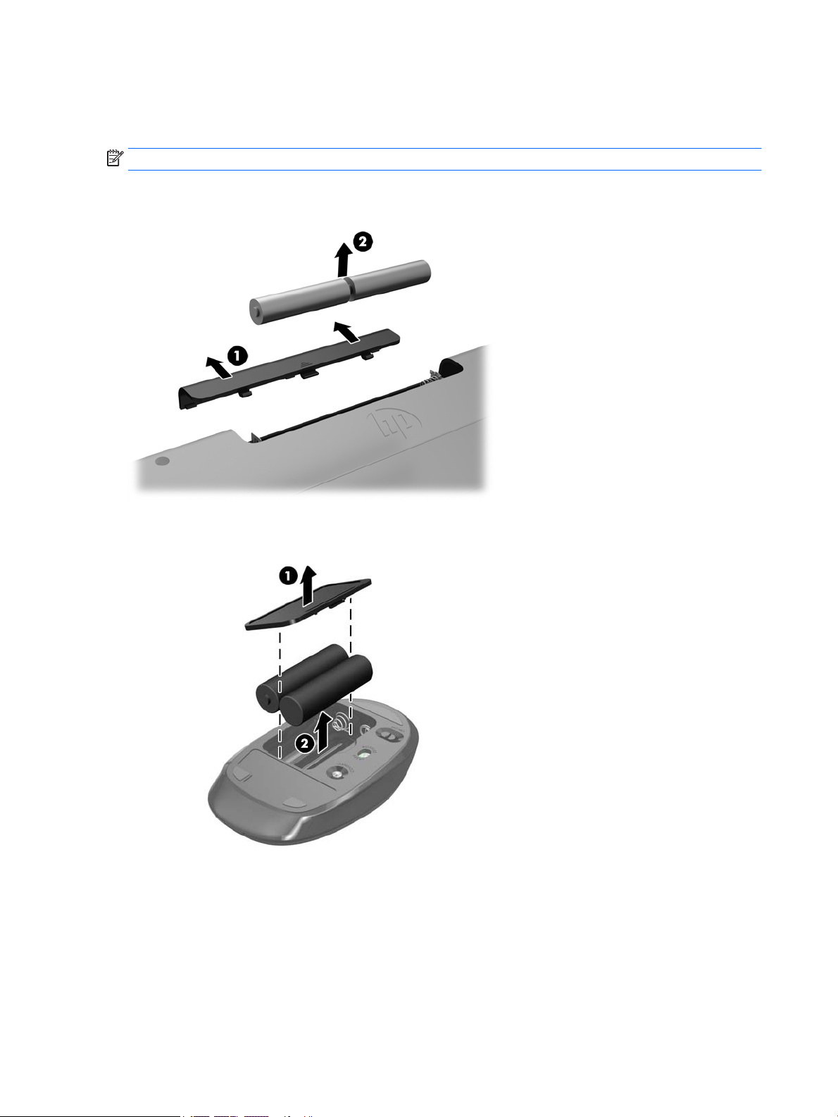
Removing batteries from the optional wireless keyboard or mouse
NOTE: The wireless keyboard and mouse are optional components.
To remove batteries from the wireless keyboard, remove the battery door on the underside of the keyboard
(1) and lift the batteries out of the battery compartment (2).
To remove batteries from the wireless mouse, remove the battery door on the underside of the mouse (1) and
lift the batteries out of the battery compartment (2).
22 Chapter 3 Hardware repair and upgrade
Page 29
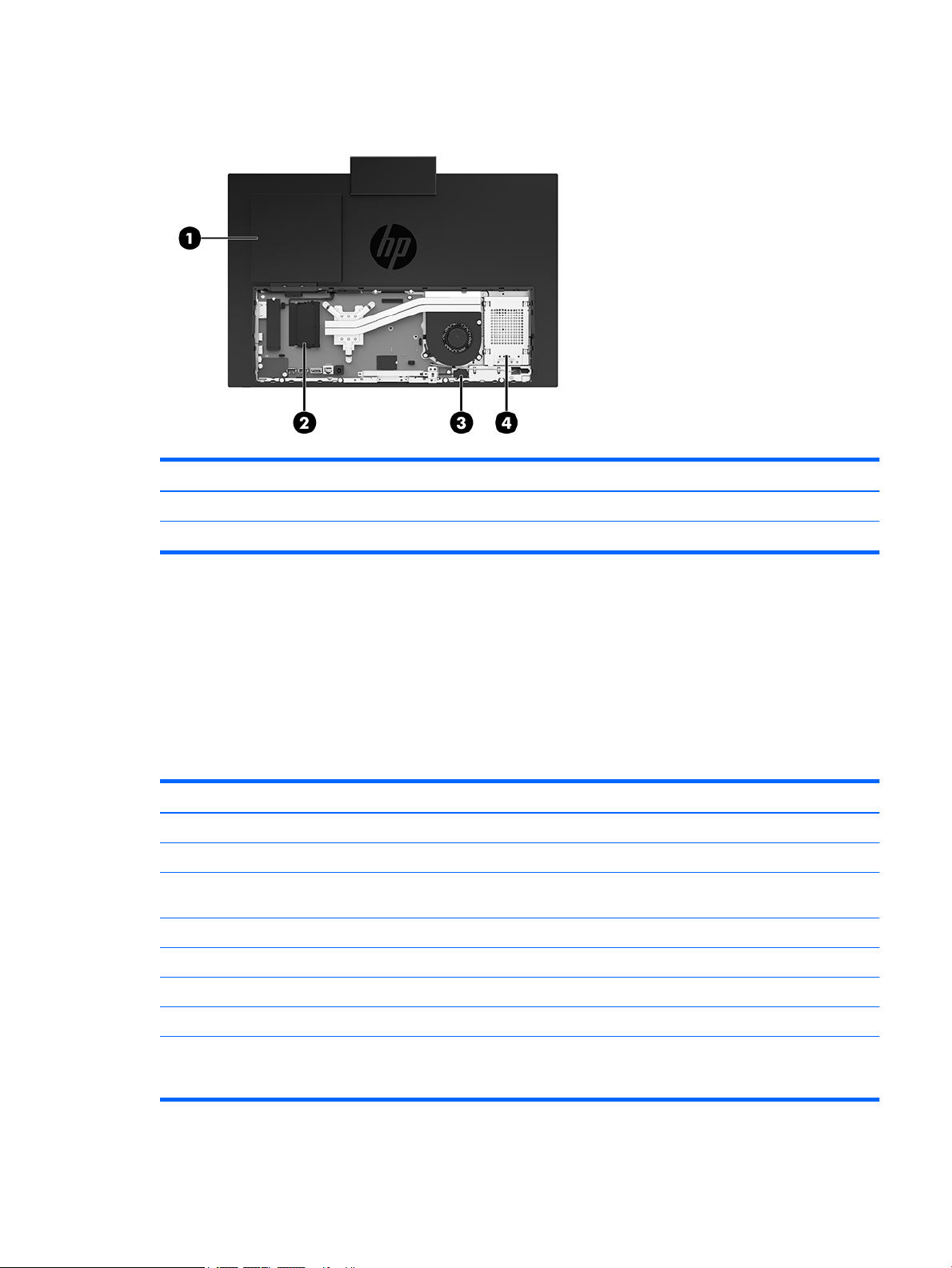
Locating internal components
Component Component
1 Optical disc drive (optional) 3 RTC battery
2 Memory modules 4 Hard drive
Removing and installing memory
The memory slots on the system board can be populated with up to two industry-standard small outline dual
inline memory modules (SODIMMs). These memory slots are populated with at least one preinstalled memory
module. A metal shield protects the memory modules.
Memory module specications
For proper system operation, the memory modules must meet the following qualications:
Component Specication
Memory modules 1.2 volt DDR4-SDRAM memory modules
Compliance Unbuered non-ECC DDR4-2666 MHz SODIMM compliant
Pins Industry-standard 260 pins containing the mandatory Joint Electronic Device
Engineering Council (JEDEC) specication
Support Support CAS latency 19 DDR4 2666 MHz (19-19-19 timing)
Slots 2
Maximum Memory 16 GB per memory slot, 32 GB total
Supported 8 Gbit (base) non-ECC memory technologies single-sided and double-sided SODIMMs
Note The system will not operate properly if you install unsupported SODIMM
memory. SODIMMs constructed with x8 and x16 DDR devices are supported; memory
modules constructed with x4 SDRAM are not supported.
Locating internal components 23
Page 30

HP oers upgrade memory for this computer and advises that the consumer purchase it to avoid
compatibility issues with unsupported third-party memory.
Populating memory module slots
The system will automatically operate in single channel mode, dual channel mode, or ex mode, depending
on how the memory modules are installed. Refer to the following table to identify the memory module
channel locations.
Location System board label Channel
Lower Socket SODIMM1 Channel B
Upper Socket SODIMM3 Channel A
The system will automatically operate in single channel mode, dual channel mode, or ex mode, depending
on how the memory modules are installed.
● The system will operate in single channel mode if the memory module slots are populated in one
channel only.
● The system will operate in a higher-performing dual channel mode if the memory capacity of the
memory module in Channel A is equal to the memory capacity of the memory module in Channel B.
● The system will operate in ex mode if the memory capacity of the memory module in Channel A is not
equal to the memory capacity of the memory module in Channel B. In ex mode, the channel populated
with the least amount of memory describes the total amount of memory assigned to dual channel and
the remainder is assigned to single channel. If one channel will have more memory than the other, the
larger amount should be assigned to channel A.
● In any mode, the maximum operational speed is determined by the slowest memory module in the
system.
24 Chapter 3 Hardware repair and upgrade
Page 31
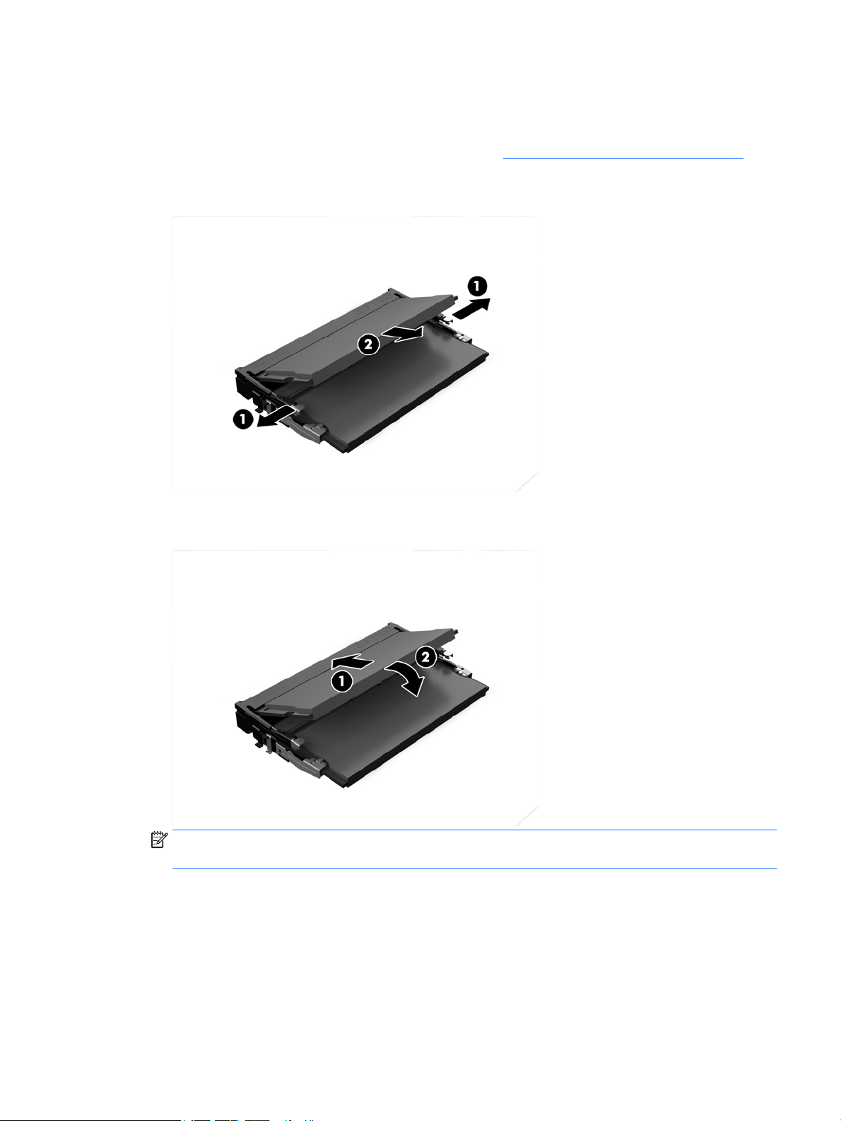
Installing memory modules
There are two memory slots on the system board. To remove or install memory modules:
1. To locate the memory modules on the system board, see Locating internal components on page 23.
2. To remove a memory module, press outward on the two latches on each side of the memory module (1),
then pull the memory module out of the slot (2).
3. Slide the new memory module into the slot at approximately a 30° angle (1), then press the memory
module down (2) so that the latches lock it in place.
NOTE: A memory module can be installed in only one way. Match the notch on the module with the tab
on the memory slot.
4. Turn on the computer. The computer automatically recognizes the additional memory when you turn on
the computer.
Removing and installing memory 25
Page 32
Replacing the RTC Battery
The battery that comes with the computer provides power to the real-time clock. When replacing the battery,
use a battery equivalent to the battery originally installed in the computer. The computer comes with a 3-volt
lithium coin cell battery.
WARNING! The computer contains an internal lithium manganese dioxide battery. There is a risk of re and
burns if the battery is not handled properly. To reduce the risk of personal injury:
Do not attempt to recharge the battery.
Do not expose to temperatures higher than 60°C (140°F).
Do not disassemble, crush, puncture, short external contacts, or dispose of in re or water.
Replace the battery only with the HP spare designated for this product.
CAUTION: Before replacing the battery, it is important to back up the computer CMOS settings. When the
battery is removed or replaced, the CMOS settings will be cleared.
Static electricity can damage the electronic components of the computer or optional equipment. Before
beginning these procedures, ensure that you are discharged of static electricity by briey touching a
grounded metal object.
NOTE: The lifetime of the lithium battery can be extended by plugging the computer into a live AC outlet.
The lithium battery is only used when the computer is NOT connected to AC power.
HP encourages customers to recycle used electronic hardware, HP original print cartridges, and rechargeable
batteries. For more information about recycling programs, go to http://www.hp.com/recycle.
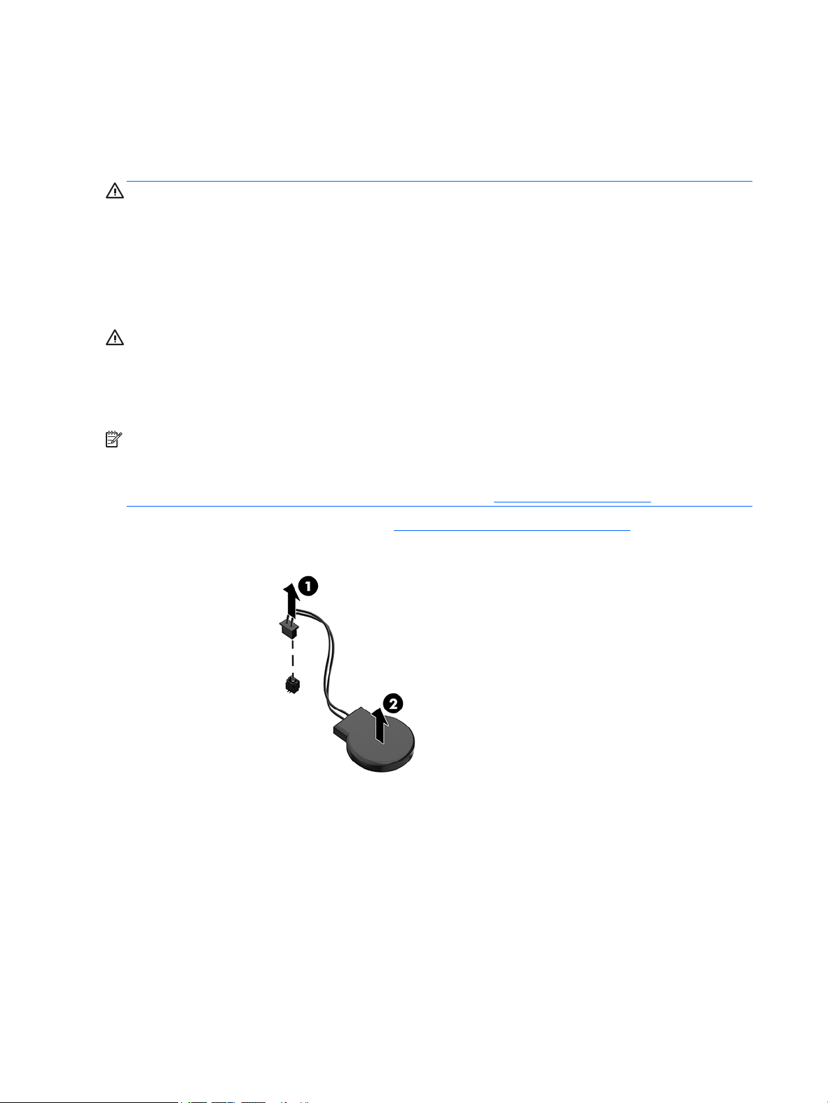
To locate the battery on the system board, see Locating internal components on page 23.
1. To release the battery, disconnect the battery cable (1), and then lift the battery from the computer (2).
2. To insert the new battery, connect the battery cable (1), and then press the battery into the computer
(2).
3. Turn on the computer.
4. Reset the date and time, your passwords, and any special system setups using Computer Setup.
26 Chapter 3 Hardware repair and upgrade
Page 33
Replacing drives
Replacing a hard drive
The 2.5 inch primary hard drive is installed on the right side of the computer. To locate the hard drive on the
system board, see Locating internal components on page 23.
Removing a hard drive
1. Remove the screw securing the hard drive to the computer.
2. Slide the hard drive away the edge of the computer and lift the hard drive out of the computer.
3. Disconnect the power and data cables from the hard drive. There is a tab you can pull to disconnect
these cables.
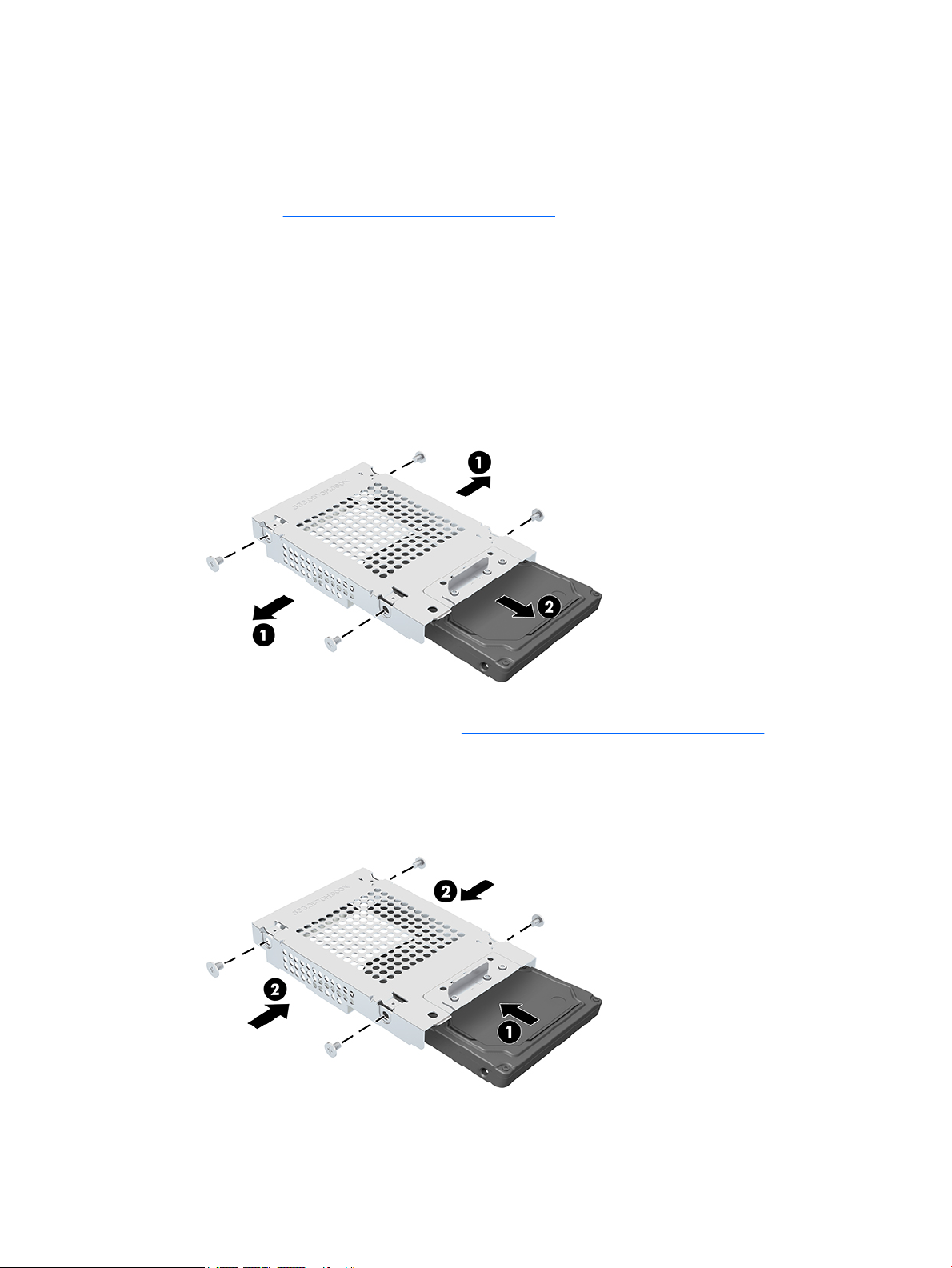
4. Remove the four mounting screws from the 2.5 inch hard drive cage (1). Be sure to keep the screws to
use to install a replacement drive. Remove the hard drive (2).
For instructions on installing a hard drive, see Installing a 2.5 inch hard disk drive on page 27.
Installing a 2.5 inch hard disk drive
1. Insert the hard drive into the drive cage (1) and fasten four mounting screws onto the new 2.5 inch hard
drive (2).
2. Position the hard drive above the drive cage with the connectors facing the power and data cables.
Replacing drives 27
Page 34
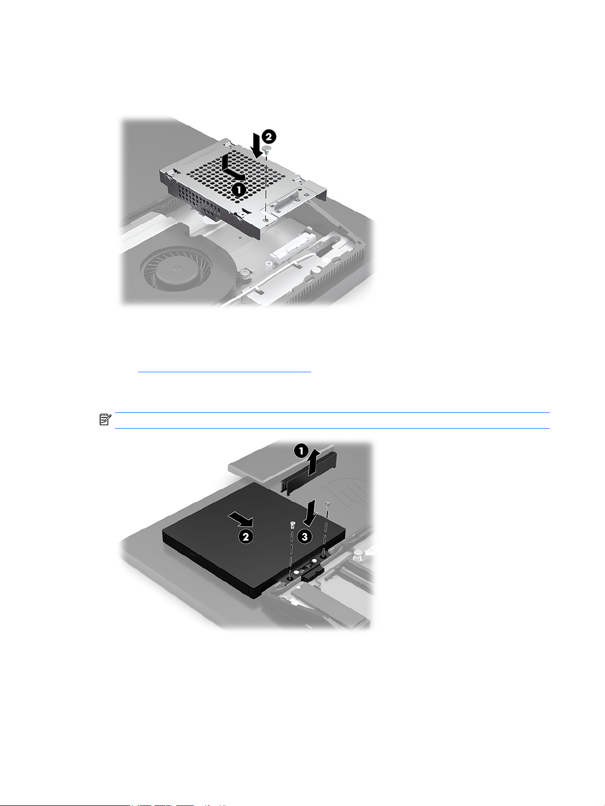
3. Connect the power and data cables to the hard drive (1).
4. Align the hard drive and slide it toward the edge of the computer until the hard drive snaps into place (1),
and then secure it with a screw (2).
Installing the optical disc drive
The optical disc drive is located above the system components. To locate the optical disc drive on the system
board, see Locating internal components on page 23.
▲ Remove the blank covering the optical disc drive connector (1) and slide the optical disc drive enclosure
into place (2). Optionally, secure it with two screws for stability (3).
NOTE: The optical disc drive can be installed in only one way.
28 Chapter 3 Hardware repair and upgrade
Page 35

A Electrostatic discharge
A discharge of static electricity from a nger or other conductor may damage system boards or other staticsensitive devices. This type of damage may reduce the life expectancy of the device.
Preventing electrostatic damage
To prevent electrostatic damage, observe the following precautions:
● Avoid hand contact by transporting and storing products in static-safe containers.
● Keep electrostatic-sensitive parts in their containers until they arrive at static-free workstations.
● Place parts on a grounded surface before removing them from their containers.
● Avoid touching pins, leads, or circuitry.
● Always be properly grounded when touching a static-sensitive component or assembly.
Grounding methods
Use one or more of the following methods when handling or installing electrostatic-sensitive parts:
● Use a wrist strap connected by a ground cord to a grounded workstation or computer chassis. Wrist
straps are exible straps with a minimum of 1 megohm +/- 10 percent resistance in the ground cords. To
provide proper ground, wear the strap snug against the skin.
● Use heelstraps, toestraps, or bootstraps at standing workstations. Wear the straps on both feet when
standing on conductive oors or dissipating oor mats.
● Use conductive eld service tools.
● Use a portable eld service kit with a folding static-dissipating work mat.
If you do not have any of the suggested equipment for proper grounding, contact an HP authorized dealer,
reseller, or service provider.
NOTE: For more information on static electricity, contact an HP authorized dealer, reseller, or service
provider.
Preventing electrostatic damage 29
Page 36

B Computer operating guidelines, routine
care, and shipping preparation
Computer operating guidelines and routine care
Follow these guidelines to properly set up and care for the computer and monitor:
● Keep the computer away from excessive moisture, direct sunlight, and extremes of heat and cold.
● Operate the computer on a sturdy, level surface. Leave a 10.2 cm (4 in) clearance on all vented sides of
the computer and above the monitor to permit the required airow.
● Never restrict the airow into the computer by blocking any vents or air intakes. Do not place the
keyboard, with the keyboard feet down, directly against the front of the desktop unit as this also
restricts airow.
● Never operate the computer with any of the access panels or any of the expansion card slot covers
removed.
● Do not stack computers or place computers so near each other that they are subject to each other’s
recirculated or preheated air.
● If the computer is to be operated within a separate enclosure, intake and exhaust ventilation must be
provided on the enclosure, and the same operating guidelines listed above will still apply.
● Keep liquids away from the computer and keyboard.
● Never cover the ventilation slots with any type of material.
● Install or enable power management functions of the operating system or other software, including
sleep states.
● Turn o the computer before you do any of the following:
● Wipe the exterior of the computer with a soft, damp cloth as needed. Using cleaning products may
discolor or damage the nish.
● Wipe the screen with a soft, clean antistatic cloth. For more dicult cleaning situations, use a
50/50 mix of water and Isopropyl alcohol. Spray the cleaner onto a cloth and use the damp cloth to
gently wipe the screen surface. Never spray the cleaner directly on the screen surface. It may run
behind the bezel and damage the electronics.
● Occasionally clean the air vents on all vented sides of the computer. Lint, dust, and other foreign
matter can block the vents and limit the airow.
● Do not use cleaners that contain any petroleum based materials such as benzene, thinner, or any
volatile substance to clean the screen or cabinet. These chemicals may damage the computer.
30 Appendix B Computer operating guidelines, routine care, and shipping preparation
Page 37

Optical disc drive precautions
Be sure to observe the following guidelines while operating or cleaning the optical disc drive.
● Do not move the drive during operation. This may cause it to malfunction during reading.
● Avoid exposing the drive to sudden changes in temperature, as condensation may form inside the unit. If
the temperature suddenly changes while the drive is on, wait at least one hour before you turn o the
power. If you operate the unit immediately, it may malfunction while reading.
● Avoid placing the drive in a location that is subject to high humidity, extreme temperatures, mechanical
vibration, or direct sunlight.
CAUTION: If any object or liquid falls into the drive, immediately unplug the computer and have it checked
by an authorized HP service provider.
Shipping preparation
Follow these suggestions when preparing to ship the computer:
1. Back up the hard drive les to an external storage device. Be sure that the backup media is not exposed
to electrical or magnetic impulses while stored or in transit.
NOTE: The hard drive locks automatically when the system power is turned o.
2. Remove and store all removable media.
3. Turn o the computer and external devices.
4. Disconnect the power cord from the AC outlet, and then from the computer.
5. Disconnect the system components and external devices from their power sources, and then from the
computer.
NOTE: Ensure that all boards are seated properly and secured in the board slots before shipping the
computer.
6. Pack the system components and external devices in their original packing boxes or similar packaging
with sucient packing material to protect them.
Optical disc drive precautions 31
Page 38

C Accessibility
HP designs, produces, and markets products and services that can be used by everyone, including people with
disabilities, either on a stand-alone basis or with appropriate assistive devices.
Supported assistive technologies
HP products support a wide variety of operating system assistive technologies and can be congured to work
with additional assistive technologies. Use the Search feature on your device to locate more information
about assistive features.
NOTE: For additional information about a particular assistive technology product, contact customer support
for that product.
Contacting support
We are constantly rening the accessibility of our products and services and welcome feedback from users. If
you have an issue with a product or would like to tell us about accessibility features that have helped you,
please contact us at (888) 259-5707, Monday through Friday, 6 a.m. to 9 p.m. Mountain Time. If you are deaf
or hard-of-hearing and use TRS/VRS/WebCapTel, contact us if you require technical support or have
accessibility questions by calling (877) 656-7058, Monday through Friday, 6 a.m. to 9 p.m. Mountain Time.
32 Appendix C Accessibility
Page 39

Index
A
accessibility 32
additional information 21
adjustable height stand 10
adjustment 16
attaching 10
removing 11
B
battery replacement 26
bottom components
HP ProOne 400 6
HP ProOne 600 4
C
cables 13
connecting 13
disconnecting 14
components
HP ProOne 400 5
HP ProOne 400 bottom 6
HP ProOne 400 front 5
HP ProOne 400 rear 6
HP ProOne 400 side 5
HP ProOne 600 2
HP ProOne 600 bottom 4
HP ProOne 600 front 2
HP ProOne 600 rear 4
HP ProOne 600 side 3
internal 23
computer operating guidelines 30
connecting
cables 13
display 13
power cord 13
D
disconnecting
cables 14
power cord 14
display connection 13
DisplayPort video adapter,
connecting 13
drive
2.5 inch, installing 27
2.5 inch, removing 27
optical disc, installing 28
types 27
E
electrostatic discharge, preventing
damage 29
F
features
keyboard 7
overview 1
xed-height stand 9
adjustment 15
attaching 9
removing 10
front components
HP ProOne 400 5
HP ProOne 600 2
G
grounding methods 29
H
hard disk drive
2.5 inch, installing 27
hard drive
2.5 inch 27
2.5 inch, removing 27
replacing 27
self-encrypting 27
solid state 27
types 27
HP ProOne 400
components 5
HP ProOne 600
components 2
I
installation guidelines 21
installing
2.5 inch hard disk drive 27
battery 26
display 13
memory 25
optical disc drive 28
internal components 23
K
keyboard
features 7
removing batteries 22
synchronizing wireless 19
L
labels
Certicate of Authenticity 8
location 8
Microsoft Certicate of
Authenticity 8
serial number 8
service 8
lock
rear port cover 14
security cable 17
M
memory 23
installing 25
maximum 23
removing 25
slots 23
SODIMMs specications 23
specications 23
Microsoft Certicate of Authenticity
label 8
mounting the computer 12
mouse
removing batteries 22
synchronizing wireless 19
O
optical disc drive
installing 28
precautions 31
Index 33
Page 40

P
port cover 14
installing 15
removing 14
power
connecting 17
disconnecting 14, 18
power cord
connecting 13
disconnecting 14
product name and number,
computer 8
R
rear components
HP ProOne 400 6
HP ProOne 600 4
rear port cover 14
installing 15
removing 14
removing
2.5 inch hard drive 27
removing battery 26
rotation 16
synchronizing wireless keyboard and
mouse 19
system memory 23
V
ventilation guidelines 30
VESA mounting holes 12
W
warnings and cautions 21
webcam 18
operation 18
Windows Hello 18
Windows Hello 18
S
security
rear port cover 14
rear port cover, installing 15
rear port cover, removing 14
security cable 17
serial number 8
setup, order of 9
shipping preparation 31
side components
HP ProOne 400 5
HP ProOne 600 3
SODIMM
identication 24
location 24
specications 23
specications, memory 23
stands
adjustable height, attaching 10
adjustable height, removing 11
attaching and removing 9
xed-height, attaching 9
xed-height, removing 10
positioning 15
34 Index
 Loading...