

HP ProOne 600, ProOne 400 Hardware Reference Manual

Hardware Reference Guide
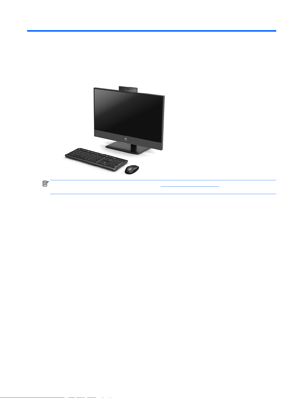
HP ProOne 600 G4 21.5-inch All-in-One Business PC
HP ProOne 400 G4 23.8-inch All-in-One Business PC
HP ProOne 400 G4 20-inch All-in-One Business PC

© Copyright 2018 HP Development Company,
L.P.
Windows is either a trademark or registered
trademark of Microsoft Corporation in the
United States and/or other countries.
The information contained herein is subject to
change without notice. The only warranties for
HP products and services are set forth in the
express warranty statements accompanying
such products and services. Nothing herein
should be construed as constituting an
additional warranty. HP shall not be liable for
technical or editorial errors or omissions
contained herein.
This document contains proprietary
information that is protected by copyright. No
part of this document may be photocopied,
reproduced, or translated to another language
without the prior written consent of HP
Development Company.
First Edition: June 2018
Document part number: L20661-001

About This Book
This guide provides basic information for upgrading this computer model.
WARNING! Text set o in this manner indicates that failure to follow directions could result in bodily harm or
loss of life.
CAUTION: Text set o in this manner indicates that failure to follow directions could result in damage to
equipment or loss of information.
NOTE: Text set o in this manner provides important supplemental information.
iii

iv About This Book

Table of contents
1 Product features ........................................................................................................................................... 1
Overview ................................................................................................................................................................ 1
HP ProOne 600 and HP ProOne 400 23.8-inch components ................................................................................ 2
Front components ............................................................................................................................... 2
Side components ................................................................................................................................. 3
Rear components ................................................................................................................................ 4
Bottom components ............................................................................................................................ 4
HP ProOne 400 20-inch components .................................................................................................................... 5
Front components ............................................................................................................................... 5
Side components ................................................................................................................................. 5
Rear components ................................................................................................................................ 6
Bottom components ............................................................................................................................ 6
Keyboard features ................................................................................................................................................. 7
Labels ..................................................................................................................................................................... 8
2 Setup ............................................................................................................................................................ 9
Overview ................................................................................................................................................................ 9
Attaching and removing a stand ............................................................................................................................ 9
Attaching and removing a xed-height stand .................................................................................... 9
Attaching a xed-height stand ......................................................................................... 9
Removing a xed-height stand ...................................................................................... 10
Attaching and removing an adjustable height stand ........................................................................ 10
Attaching an adjustable height stand ............................................................................ 10
Removing an adjustable height stand ............................................................................ 11
Attaching the computer to a mounting xture ................................................................................................... 12
Connecting and disconnecting cables ................................................................................................................. 13
Connecting cables ............................................................................................................................. 13
Connecting a display ......................................................................................................................... 13
Disconnecting cables ......................................................................................................................... 14
Removing and installing the rear port cover ....................................................................................................... 14
Removing the rear port cover ........................................................................................................... 14
Installing the rear port cover ............................................................................................................ 15
Positioning the computer .................................................................................................................................... 15
Adjusting a xed-height stand .......................................................................................................... 15
Adjusting an adjustable height stand ............................................................................................... 16
Installing a security cable .................................................................................................................................... 17
v

Connecting and disconnecting power ................................................................................................................. 17
Connecting power .............................................................................................................................. 17
Disconnecting power ......................................................................................................................... 18
Webcam ............................................................................................................................................................... 18
Webcam operation ............................................................................................................................ 18
Setting up Windows Hello ................................................................................................................. 18
Synchronizing the optional wireless keyboard and mouse ................................................................................ 19
3 Hardware repair and upgrade ....................................................................................................................... 21
Warnings and cautions ........................................................................................................................................ 21
Additional information ........................................................................................................................................ 21
Removing batteries from the optional wireless keyboard or mouse ................................................................. 22
Locating internal components ............................................................................................................................ 23
Removing and installing memory ....................................................................................................................... 23
Memory module specications ......................................................................................................... 23
Populating memory module slots .................................................................................................... 24
Installing memory modules .............................................................................................................. 25
Replacing the RTC Battery ................................................................................................................................... 26
Replacing drives ................................................................................................................................................... 27
Replacing a hard drive ....................................................................................................................... 27
Removing a hard drive .................................................................................................... 27
Installing a 2.5 inch hard disk drive ................................................................................ 27
Installing the optical disc drive ......................................................................................................... 28
Appendix A Electrostatic discharge .................................................................................................................. 29
Preventing electrostatic damage ........................................................................................................................ 29
Grounding methods ............................................................................................................................................. 29
Appendix B Computer operating guidelines, routine care, and shipping preparation ............................................ 30
Computer operating guidelines and routine care ............................................................................................... 30
Optical disc drive precautions ............................................................................................................................. 31
Shipping preparation ........................................................................................................................................... 31
Appendix C Accessibility ................................................................................................................................. 32
Supported assistive technologies ....................................................................................................................... 32
Contacting support .............................................................................................................................................. 32
Index ............................................................................................................................................................. 33
vi
1 Product features
Overview
NOTE: For the latest manuals on this product, go to http://www.hp.com/support. Select Find your product,
and then follow the on-screen instructions.
Overview 1
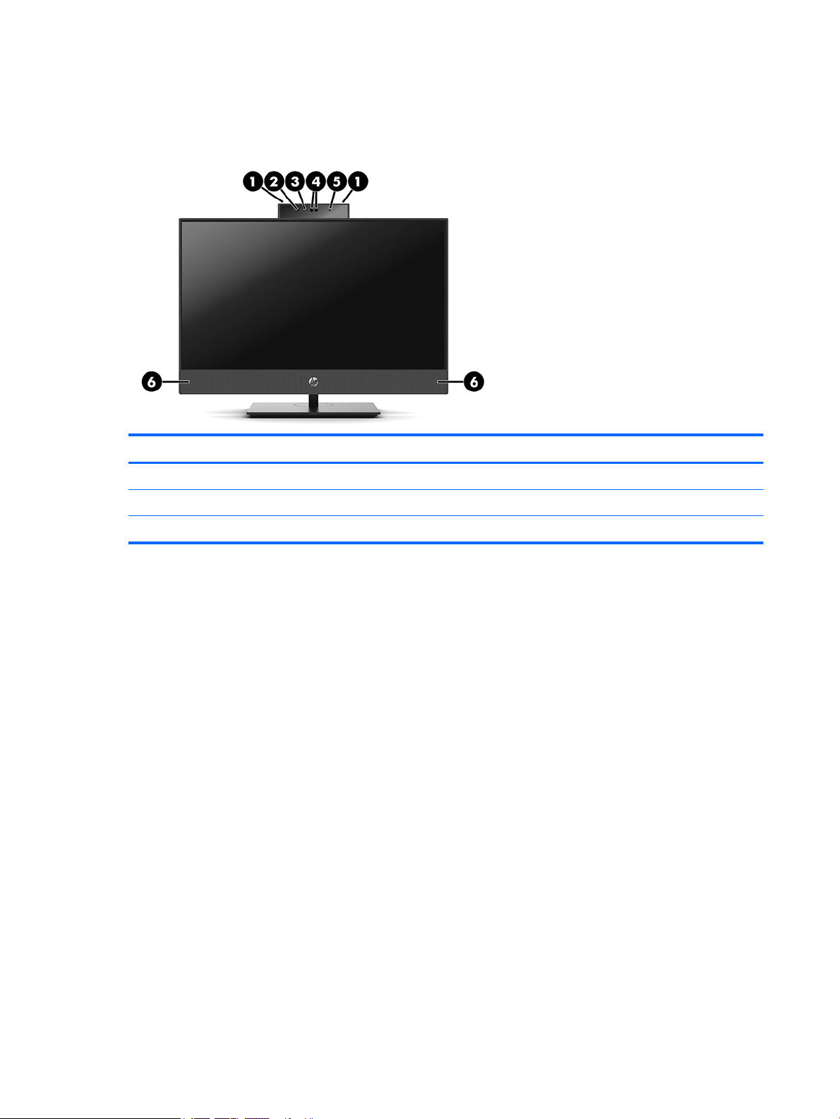
HP ProOne 600 and HP ProOne 400 23.8-inch components
Front components
Component Component
1 Webcam microphones (2) (optional) 4 Webcam/IR lens (optional)
2 IR LED (optional) 5 IR LED (optional)
3 Webcam LED (optional) 6 Speakers (2) (optional)
2 Chapter 1 Product features

Side components
Component Component
1 Optical disc drive (optional) 5 USB 3.1 Type-C port
2 Optical disc drive light (optional) 6 USB 3.1 Type-A (charging) port
3 Optical disc drive eject button (optional) 7 USB 3.1 Type-A port
4 SD card reader (optional) 8 Audio-out (headphone)/Audio-in (microphone) combo jack
HP ProOne 600 and HP ProOne 400 23.8-inch components 3
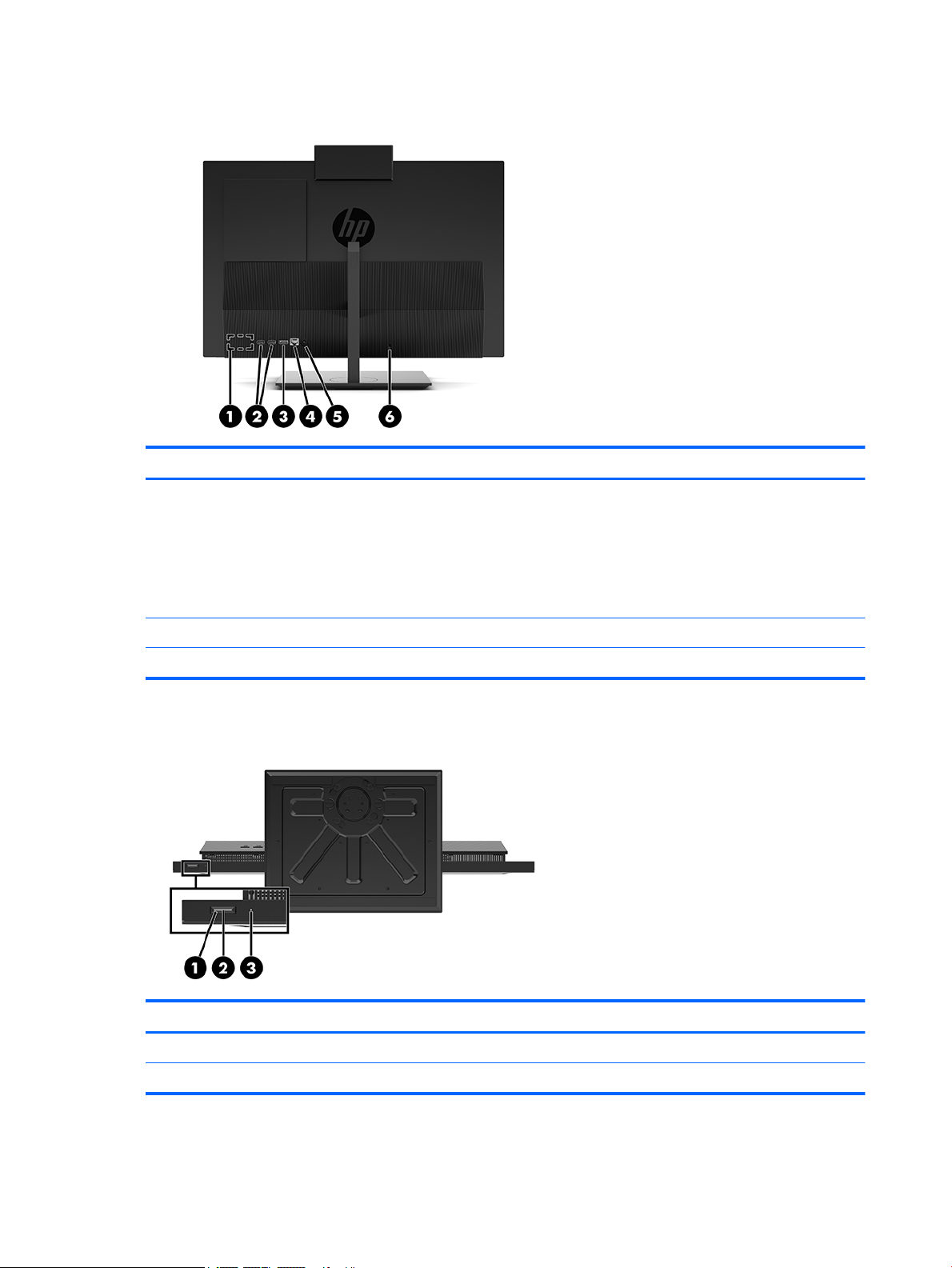
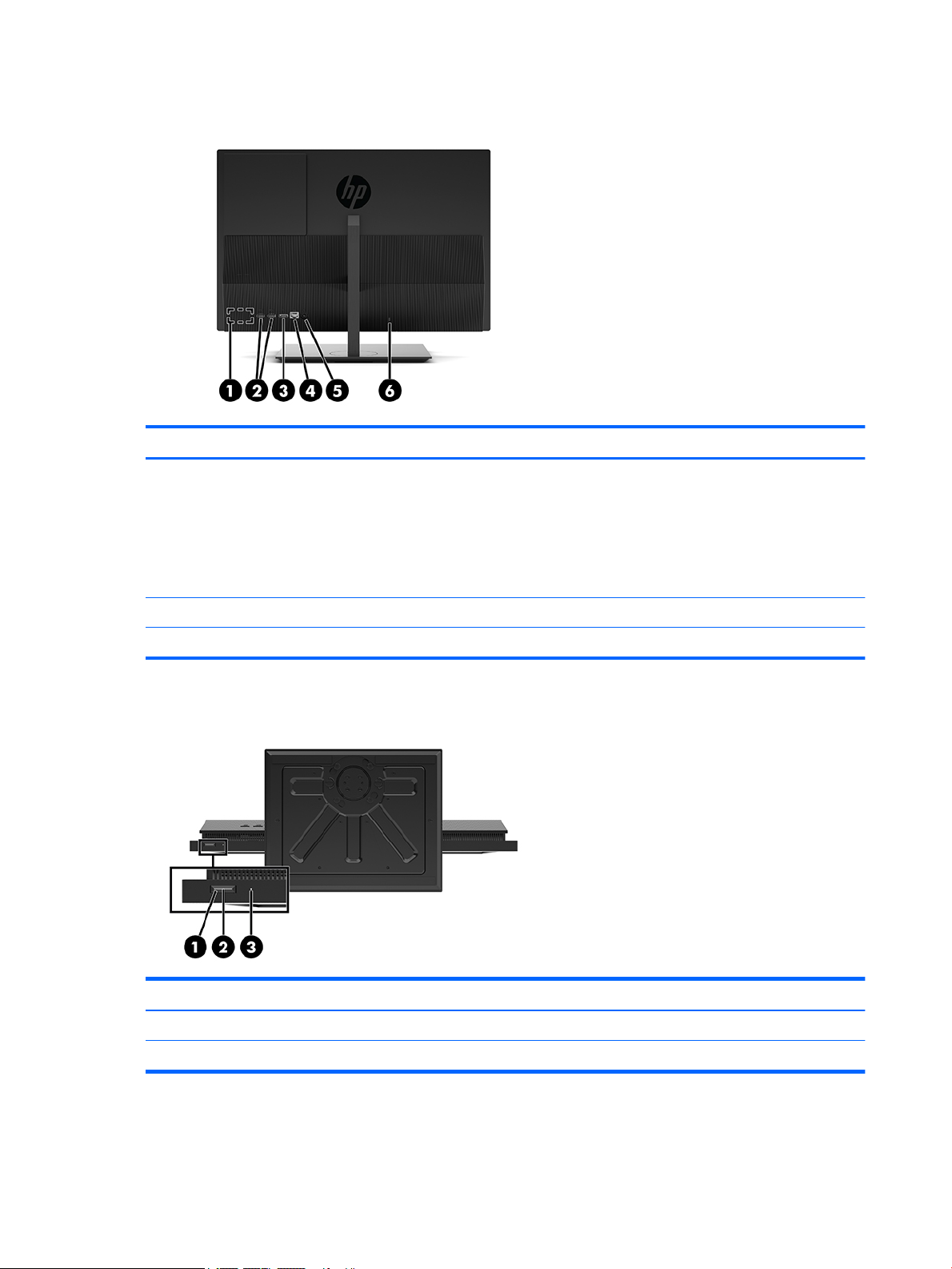
Rear components
Component Component
1 DisplayPort port (optional)
– or –
HDMI port (optional)
– or –
Serial port (optional)
2 USB 3.1 Type-A ports (2) 5 Power connector
3 DisplayPort port 6 Security cable slot
Bottom components
4 RJ-45 (network) jack
Component Component
1 Power button 3 Hard drive activity light
2 Power light
4 Chapter 1 Product features
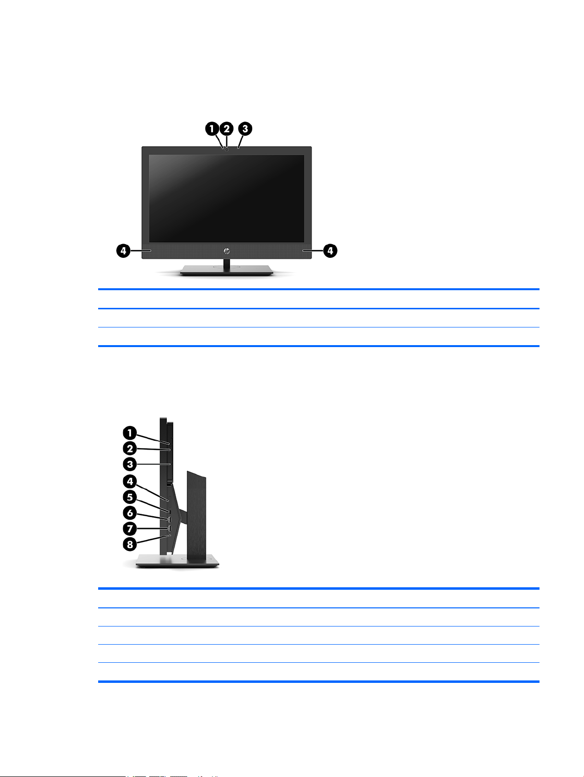
HP ProOne 400 20-inch components
Front components
Component Component
1 Webcam LED 3 Webcam microphone
2 Webcam lens 4 Speakers (2) (optional)
Side components
Component Component
1 Optical disc drive (optional) 5 USB 3.1 Type-C port
2 Optical disc drive light (optional) 6 USB 3.1 Type-A (charging) port
3 Optical disc drive eject button (optional) 7 USB 3.1 Type-A port
4 SD card reader (optional) 8 Audio-out (headphone)/Audio-in (microphone) combo jack
HP ProOne 400 20-inch components 5
Rear components
Component Component
1 DisplayPort port (optional)
– or –
HDMI port (optional)
– or –
Serial port (optional)
2 USB 3.1 Type-A ports (2) 5 Power connector
3 DisplayPort port 6 Security cable slot
Bottom components
4 RJ-45 (network) jack
Component Component
1 Power button 3 Hard drive activity light
2 Power light
6 Chapter 1 Product features
 Loading...