

Page 1

HP ProLiant SL4545 G7 Server Node
Part Number: 683994-003
User Guide
Abstract
This document is for the person who installs, administers, and troubleshoots servers and storage systems. HP assumes you are qualified in the
servicing of computer equipment and trained in recognizing hazards in products with hazardous energy levels.
February 2013
Edition: 3
Page 2

© Copyright 2012, 2013 Hewlett-Packard Development Company, L.P.
The information contained herein is subject to change without notice. The only warranties for HP products and services are set forth in the express
warranty statements accompanying such products and services. Nothing herein should be construed as constituting an additional warranty. HP shall
not be liable for technical or editorial errors or omissions contained herein.
Microsoft® and Windows® are U.S. registered trademarks of Microsoft Corporation.
Page 3

Contents
Component identification ............................................................................................................... 6
Node component identification ................................................................................................................... 6
Front panel components ................................................................................................................... 6
Front panel LEDs and buttons ............................................................................................................ 6
System board components ................................................................................................................ 7
Personality board components ......................................................................................................... 10
Chassis component identification ............................................................................................................... 10
Front panel components ................................................................................................................. 11
Rear panel components .................................................................................................................. 14
Operations ................................................................................................................................. 21
Powering up the system ............................................................................................................................ 21
Power down the node .............................................................................................................................. 21
Remove a node from the chassis ................................................................................................................ 21
Remove the access panel.......................................................................................................................... 22
Install the access panel............................................................................................................................. 23
Remove the processor air baffle ................................................................................................................ 23
Setup ......................................................................................................................................... 24
Optional installation services .................................................................................................................... 24
Rack planning resources........................................................................................................................... 24
Optimum environment .............................................................................................................................. 24
Space and airflow requirements ...................................................................................................... 25
Temperature requirements ............................................................................................................... 25
Power requirements ....................................................................................................................... 26
Electrical grounding requirements .................................................................................................... 26
Rack warnings ........................................................................................................................................ 26
Installing the chassis ................................................................................................................................ 27
Installing hardware options ....................................................................................................................... 27
Installing a node into the chassis ............................................................................................................... 27
Configuring the chassis ............................................................................................................................ 28
Powering up and configuring the server ..................................................................................................... 28
Installing the operating system for G7 servers .............................................................................................. 28
Deploying management software .............................................................................................................. 28
Discovering and provisioning new devices ................................................................................................. 29
Registering the server ............................................................................................................................... 29
Hardware options installation ....................................................................................................... 30
Introduction ............................................................................................................................................ 30
Processor option ...................................................................................................................................... 30
Memory options ...................................................................................................................................... 35
Memory subsystem architecture ....................................................................................................... 35
Single-rank and dual-rank DIMMs .................................................................................................... 35
DIMM identification ....................................................................................................................... 36
Memory configurations ................................................................................................................... 36
General DIMM slot population guidelines ......................................................................................... 37
Installing a DIMM .......................................................................................................................... 38
Contents 3
Page 4

Hot-plug hard drive guidelines .................................................................................................................. 38
Removing a drive blank .................................................................................................................. 39
Installing a hot-plug SATA hard drive ............................................................................................... 39
Controller options .................................................................................................................................... 40
HP Trusted Platform Module option ............................................................................................................ 40
Installing the Trusted Platform Module board ..................................................................................... 41
Retaining the recovery key/password .............................................................................................. 42
Enabling the Trusted Platform Module ............................................................................................... 43
Cabling ..................................................................................................................................... 44
Personality board cabling ......................................................................................................................... 44
SATA cabling ......................................................................................................................................... 44
Internal power cabling ............................................................................................................................. 44
RPS cabling ............................................................................................................................................ 45
Front LED cabling .................................................................................................................................... 45
SFF backplane power cabling ................................................................................................................... 46
USB/VGA cabling ................................................................................................................................... 46
Software and configuration utilities ............................................................................................... 47
Configuration tools .................................................................................................................................. 47
HP Service Pack for ProLiant............................................................................................................ 47
HP ROM-Based Setup Utility ............................................................................................................ 48
Array Configuration Utility .............................................................................................................. 50
Option ROM Configuration for Arrays ............................................................................................. 50
Re-entering the server serial number and product ID ........................................................................... 51
Management tools ................................................................................................................................... 51
Automatic Server Recovery ............................................................................................................. 51
ROMPaq utility .............................................................................................................................. 52
iLO technology .............................................................................................................................. 52
Redundant ROM support ................................................................................................................ 52
USB support .................................................................................................................................. 53
Diagnostic tools ...................................................................................................................................... 53
HP Insight Diagnostics .................................................................................................................... 53
Integrated Management Log ........................................................................................................... 54
Remote support and analysis tools ............................................................................................................. 54
HP Insight Remote Support software ................................................................................................. 54
Keeping the system current ....................................................................................................................... 55
Drivers ......................................................................................................................................... 55
Software and firmware ................................................................................................................... 55
Version control .............................................................................................................................. 55
Operating System Version Support .................................................................................................. 55
Change control and proactive notification ........................................................................................ 55
Care Pack .................................................................................................................................... 56
System battery ............................................................................................................................ 57
Regulatory information ................................................................................................
Safety and regulatory compliance ............................................................................................................. 58
Turkey RoHS material content declaration ................................................................................................... 58
Ukraine RoHS material content declaration ................................................................................................. 58
Warranty information .............................................................................................................................. 58
................ 58
Electrostatic discharge ................................................................................................................. 59
Preventing electrostatic discharge .............................................................................................................. 59
Grounding methods to prevent electrostatic discharge .................................................................................. 59
Contents 4
Page 5

Specifications ............................................................................................................................. 60
Environmental specifications ..................................................................................................................... 60
Hot-plug power supply calculations ............................................................................................................ 60
Support and other resources ........................................................................................................ 61
Before you contact HP .............................................................................................................................. 61
HP contact information ............................................................................................................................. 61
Customer Self Repair ............................................................................................................................... 61
Appendix: Install the hpahcisr driver for OS installation .................................................................. 69
Installing a Windows or Linux OS ............................................................................................................. 69
Enabling SATA RAID functionality in RBSU ........................................................................................ 69
Creating a drivers diskette for Windows 2008 SP1 OS ...................................................................... 69
Installing a Windows OS ................................................................................................................ 70
Creating a drivers diskette for Linux OS ............................................................................................ 70
Installing a Linux OS ...................................................................................................................... 71
Acronyms and abbreviations ........................................................................................................ 72
Documentation feedback ............................................................................................................. 75
Index ......................................................................................................................................... 76
Contents 5
Page 6
Component identification
Node component identification
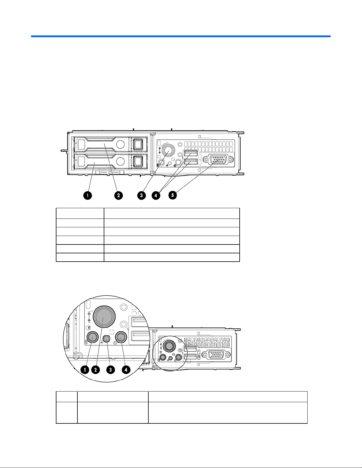
Front panel components
Item Description
1
2
3
4
5
Hard drive bay 1
Hard drive bay 2
Node release button
USB connectors (2)
VGA connector
Front panel LEDs and buttons
Item Description Status
1
UID LED button Blue = Activated
Flashing blue = System is being remotely managed or firmware
update is in progress.
Component identification 6
Page 7
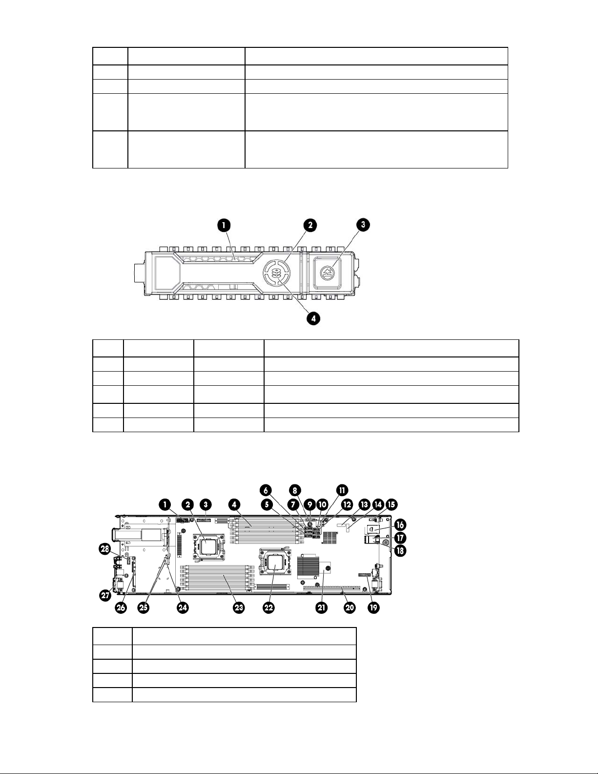
Item Description Status
Reserved
—
—
2
3
4
Node release button —
System Health LED Green = Normal
Power On/Standby button
and system power LED
Drive LED definitions
Off = Deactivated
Flashing amber = System degraded
Flashing red = System critical
Green = System on
Amber = System is in Standby mode, but power is still applied.
Off = Power is not connected, or power supply has failed.
Item LED Status Definition
1
2
3
4
Activity ring Rotating green Drive activity
Off No drive activity
Reserved — —
Reserved — —
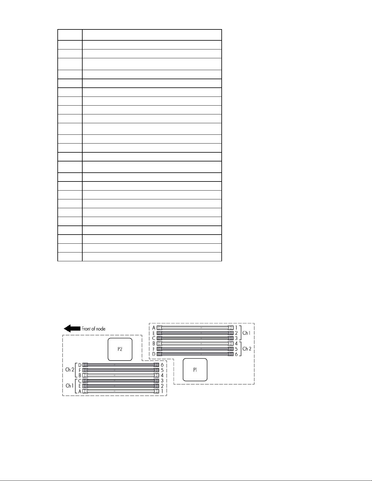
System board components
Item Description
1
2
3
4
Power connector
Processor socket 2
RPS connector
Processor 1 DIMM slots (6)
Component identification 7
Page 8
Item Description
5
6
7
Reserved connector
SATA 1 connector
SATA 2 connector
8
9
10
11
12
13
14
15
16
17
18
19
20
21
22
23
24
25
26
27
28
Reserved connector
System battery
Reserved connector
Internal USB connector
Reserved connector
System maintenance switch (SW1)
System maintenance switch (SW4)
LED power connector
iLO connector
NIC 1 connector (bottom)
NIC 2 connector (top)
USB/VGA connector
Personality board connector
TPM connector
Processor socket 1
Processor 2 DIMM slots (6)
SFF backplane power connector
SATA connectors (2)
Front panel USB/VGA connector
VGA connector
Front LED connector
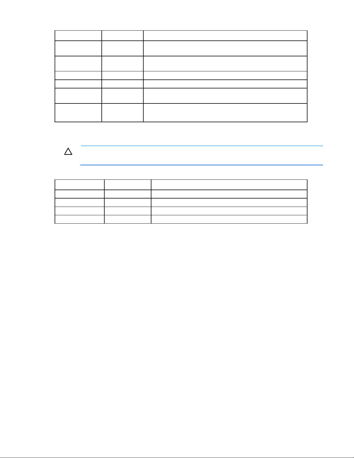
DIMM slots
DIMM slots are numbered sequentially (1 through 6) for each processor. The supported AMP modes use the
alpha assignments for population order, and the slot numbers designate the DIMM slot ID for spare
replacement.
System board switches
System maintenance switch
Component identification 8
Page 9
Position Default Function
S1
S2
S3
S4
S5
S6
Off Off—iLO security is enabled.
On—iLO security is disabled.
Off Off—System configuration can be changed.
On—System configuration is locked.
Off Reserved
Off Reserved
Off Off—Power-on password enabled.
On—Power-on password disabled.
Off Off—No function
On—ROM reads system configuration as invalid.
When the system maintenance switch position 6 is set to the On position, the system is prepared to erase all
system configuration settings from both CMOS and NVRAM.
CAUTION: Clearing CMOS and/or NVRAM deletes configuration information. There is an
RBSU setting that erases default settings and fixed disk partitions, which causes a loss of data.
Diagnostic LEDs
Position Position Function
S7
Off
Off
On
S8 Diagnostic LEDs
Off Port 85
On Port 84
Off iLO
NMI jumper
The NMI jumper allows administrators to perform a memory dump before performing a hard reset. Crash
dump analysis is an essential part of eliminating reliability problems, such as hangs or crashes in OSs, device
drivers, and applications. Many crashes can freeze a system, requiring you to do a hard reset. Resetting the
system erases any information that would support root cause analysis.
Systems running Microsoft® Windows® experience a blue-screen trap when the OS crashes. When this
happens, Microsoft® recommends that system administrators perform an NMI event by temporarily shorting
the NMI header with a jumper. The NMI event enables a hung system to become responsive again.
Component identification 9
Page 10
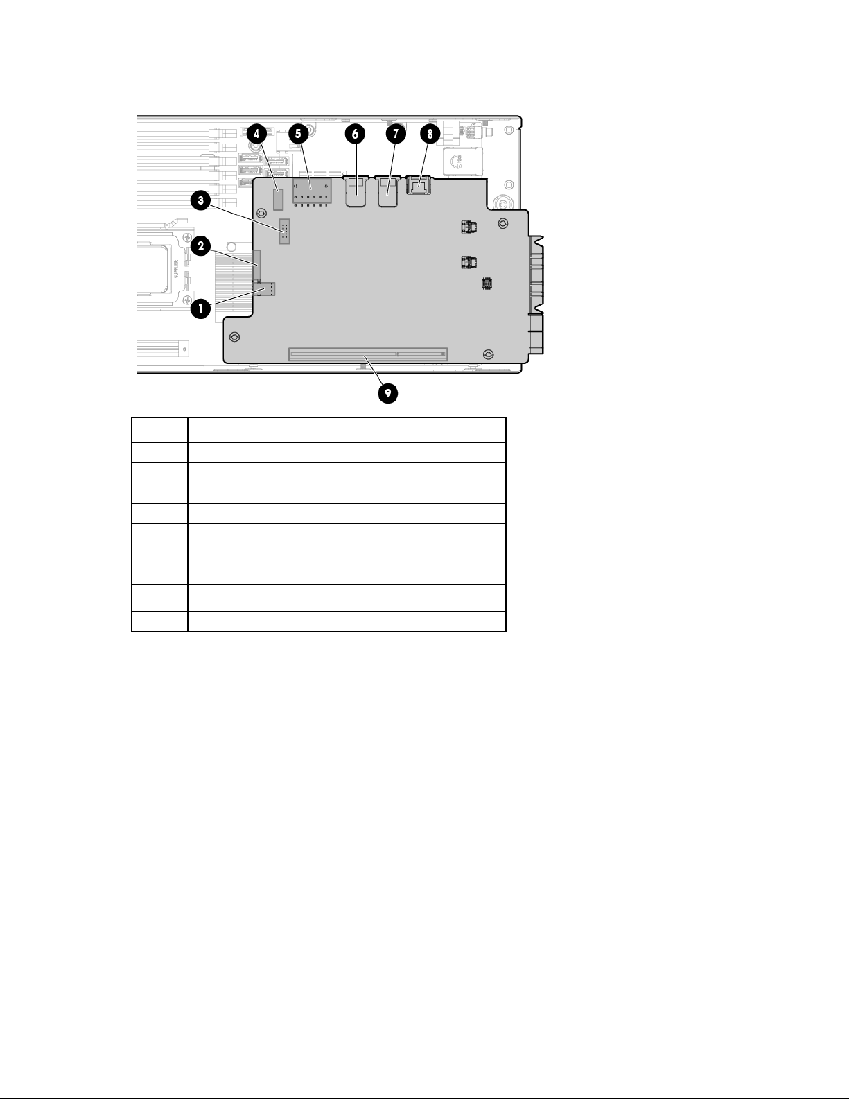
Personality board components
Item Description
1
2
3
4
5
6
7
8
9
*This connector is on the bottom of the personality board.
Hard drive power connector
RPS connector
Serial connector*
LED cable connector*
Power connector
NIC 1 connector
NIC 2 connector
iLO connector
x24 personality board assembly connector
Chassis component identification
The following sections provide information on chassis LEDs and connectors. For information on chassis
options installation, see the HP ProLiant SL4500 Series Setup and Installation Guide. For information on
component removal and replacement, see the HP ProLiant SL4500 Series Chassis Maintenance and Service
Guide.
Component identification 10
Page 11
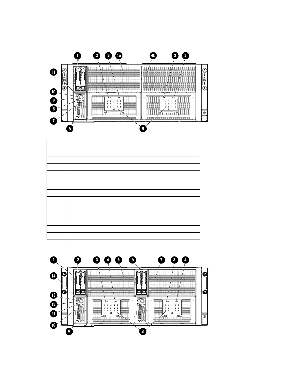
Front panel components
• 1 node chassis
Item Description
1
2
3
4
5
6
7
8
9
10
11
Node drives
LFF drive health LED
LFF drive UID
Drives controlled by the array controller
a. Port 1i
b. Port 2i
Drive display boards
Node VGA connector
Node USB connectors
Node Power On/Standby button and system power LED
Node health LED
Node release button
Node UID LED button
• 2 node chassis
Component identification 11
Page 12
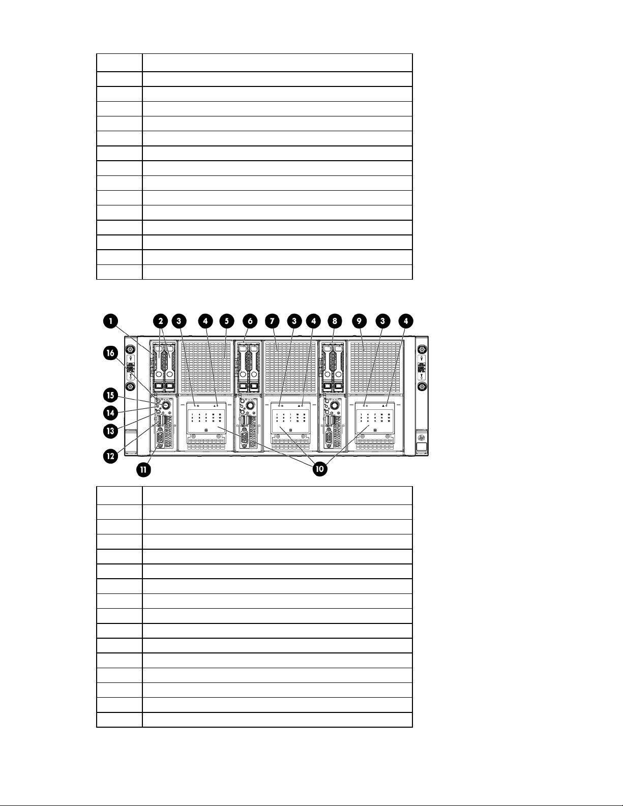
Drive display boards
Item Description
1
2
3
4
5
6
7
8
9
10
11
12
13
14
Node 1
Node drives
LFF drive health LED
LFF drive UID
Drives controlled by node 1 P420i array controller
Node 2
Drives controlled by node 2 P420i array controller
Node VGA connector
Node USB connectors
Node Power On/Standby button and system power LED
Node health LED
Node release button
Node UID LED button
• 3 node chassis
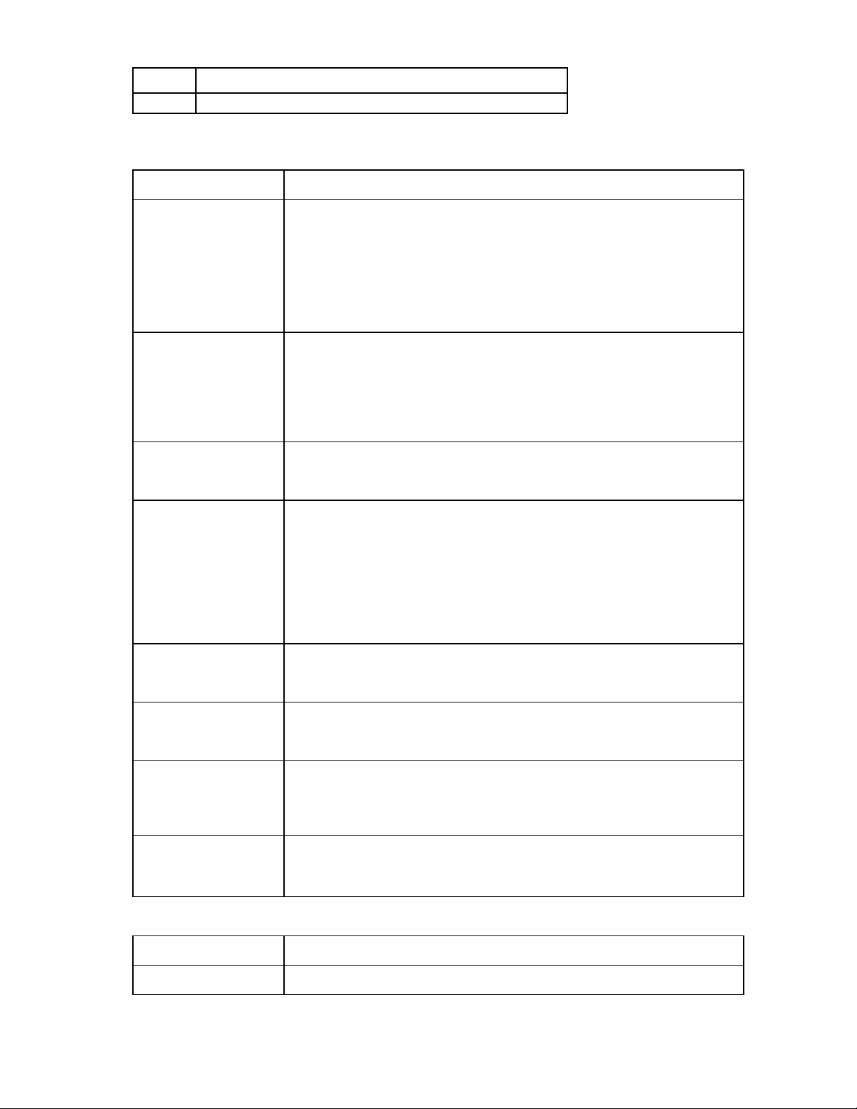
Item Description
1
2
3
4
5
6
7
8
9
10
11
12
13
14
15
Node 1
Node drives
LFF drive health LED
LFF drive UID
Drives controlled by node 1 Smart Array controller
Node 2
Drives controlled by node 2 Smart Array controller
Node 3
Drives controlled by node 3 Smart Array controller
Drive display boards
Node VGA connector
Node USB connectors
Node Power On/Standby button and system power LED
Node health LED
Node release button
Component identification 12
Page 13
•
•
•
•
•
•
•
•
•
•
•
•
•
•
•
•
•
•
Both of the following conditions apply:
•
•
•
•
•
•
•
Item Description
16
Node UID LED button
Hard drive display LEDs
LED behavior Definition
Off
Solid green
Solid green with UID
flashing
Flicker with drive activity
Flashing at 1Hz 50% duty
cycle
Solid amber
Flashing amber at 1Hz
50% duty cycle
Alternating amber and
green at 1 Hz 50% duty
cycle
Drive is not installed.
Drive is not a member of any RAID volumes.
Drive is a spare drive that is inactive or has been activated but has not been
rebuilt.
Notes:
Drive is not rebuilding.
Drive is not a volume undergoing capacity expansion.
All of the following conditions apply:
Drive is a member of a RAID volume.
Drive is not an inactive spare drive.
Drive is not in a replacement or failed state for any volume that is a member of a
RAID volume.
Drive is not currently performing I/O.
Both of the following conditions apply:
Drive is not failed.
Drive is selected (UID identification).
All of the following conditions apply:
Drive is currently performing I/O activity.
Drive is a member of a RAID volume.
Drive is not in a replacement or failed state for any volumes that it is a member
of (drive is online).
Drive is not rebuilding.
Drive is not a member of a volume undergoing capacity expansion or RAID
migration.
Drive is rebuilding.
Drive is a member of a volume undergoing capacity expansion or RAID
migration.
Drive is failed.
Drive is not selected.
All of the following conditions apply:
Drive is in a predictive failure state.
Drive is not failed.
Drive is not selected.
Drive is failed.
Drive is in a predictive failure state.
In either instance, the drive is selected.
Hard drive health LEDs
LED behavior Definition
Off
System is off.
Component identification 13
Page 14
LED behavior Definition
Normal operating mode
I/O module
Green
Amber
Storage system health is good.
System requires service or a fault is detected. Check hard drives, hard drive
backplane, RAID controller, and system fans.
UID LEDs
LED behavior Definition
Off
Blue flashing
Hard drive segment is selected; hard drive is in locate mode. Firmware is being
flashed.
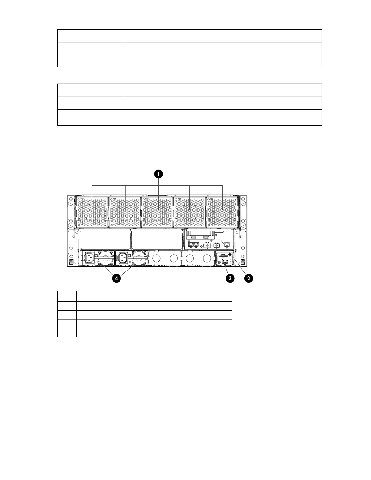
Rear panel components
• 1 node chassis
Item Description
1
2
3
4
System fans
Management module
Power supplies
Component identification 14
Page 15
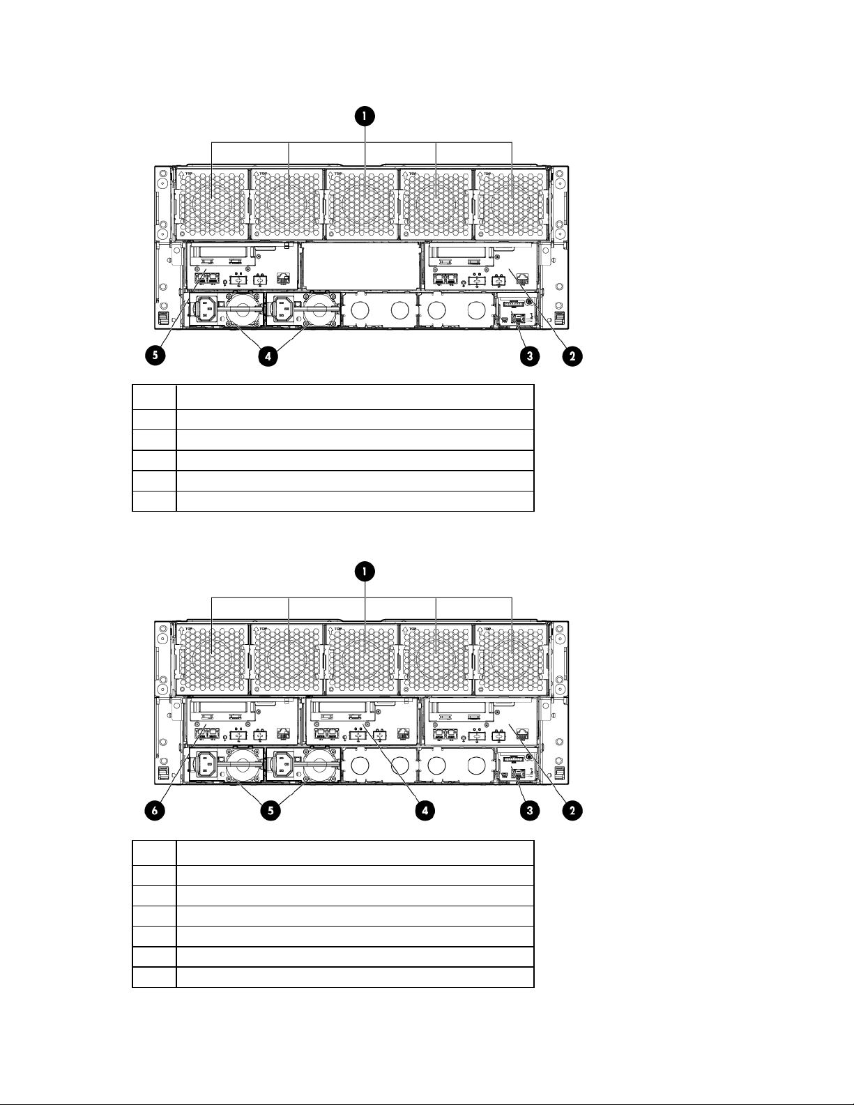
• 2 node chassis
System fans
Item Description
1
2
3
4
5
System fans
I/O module for node 1
Management module
Power supplies
I/O module for node 2
• 3 node chassis
Item Description
1
2
3
4
5
6
I/O module for node 1
Management module
I/O module for node 2
Power supplies
I/O module for node 3
Component identification 15
Page 16
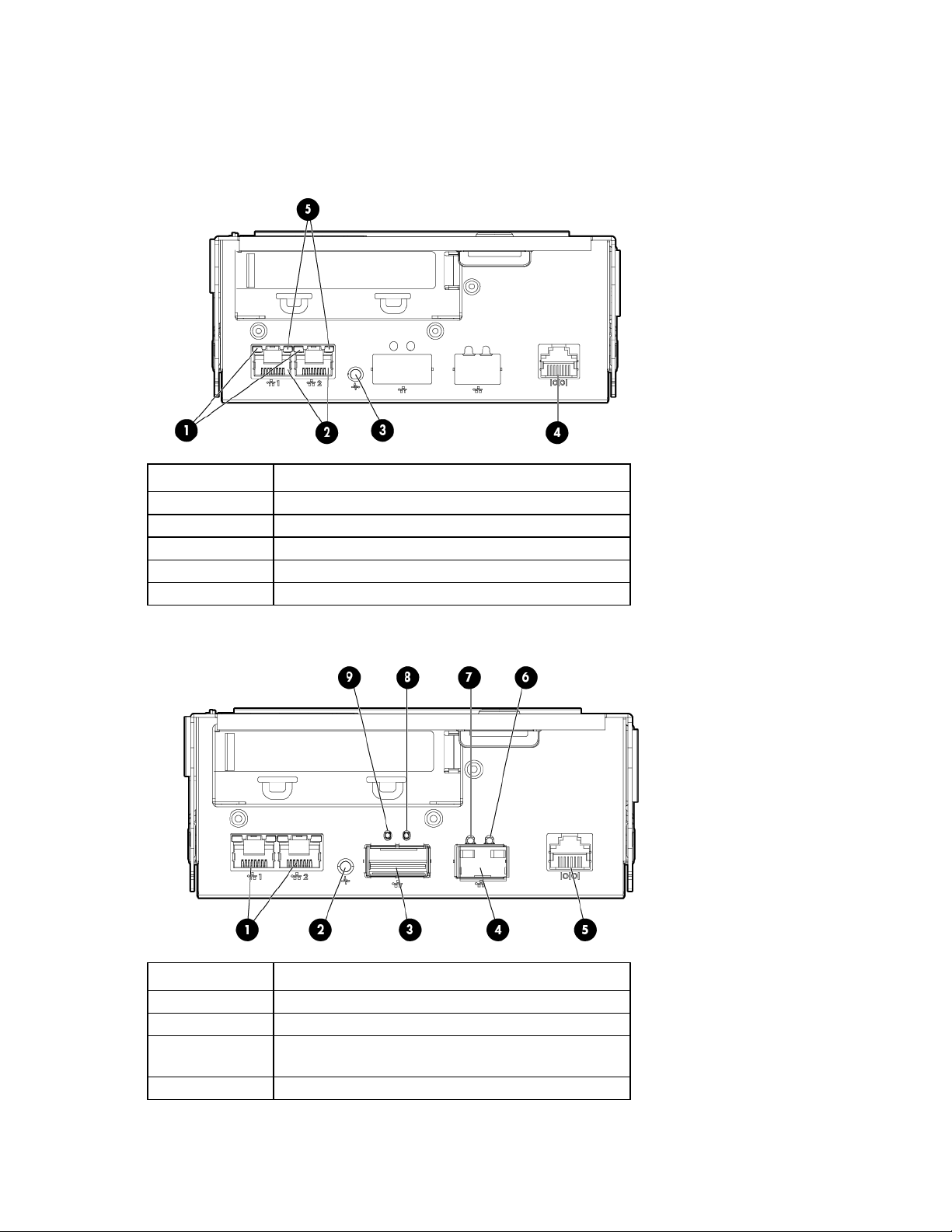
I/O module connectors and LEDs
• 1 Gb I/O module
Item Description
1
2
3
4
5
Activity LED
1Gb connectors
I/O module health LED
Serial connector
Link LED
• 10 Gb I/O module
Item Description
1
2
3
4
1 Gb connectors
I/O module health LED
QSFP 10 Gb Ethernet or 40Gb IB connector, depending
on configuration
SFP+ 10Gb Ethernet connector
Component identification 16
Page 17
•
•
•
Item Description
5
6
7
8
9
Serial connector
Link LED
Activity LED
Activity LED
Link LED
Description Status
Health LED
Off = I/O module is in good health.
Amber = I/O module has one of the following health
issues:
Thermal alarm on a mezzanine card
I/O module power has failed on one of the power
rails.
The I/O module is not fully seated in the connector.
1Gb link LED
1Gb activity LED
10Gb/40Gb link LED
10Gb/40Gb activity
LED
Green = Network link
Off = No network link
Flashing green = Network activity
Off = No network activity
Green = Network link
Off = No network link
Flashing amber = Network activity
Off = No network activity
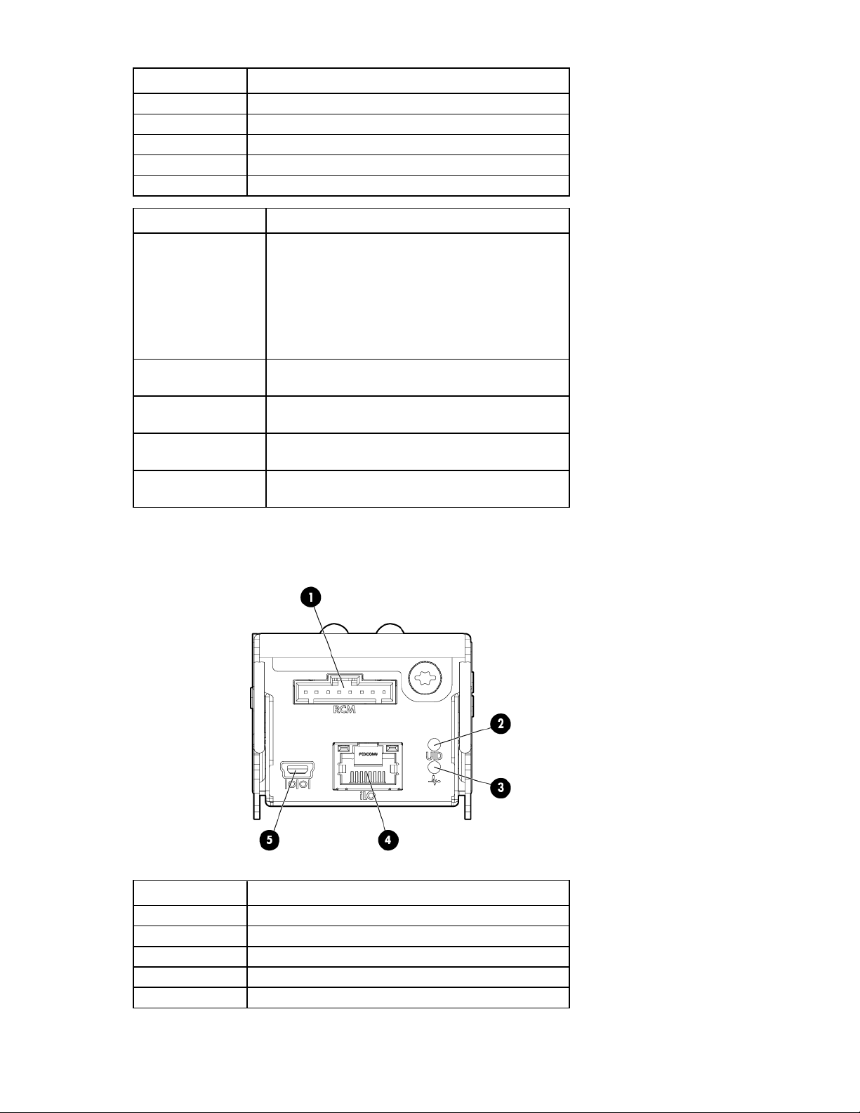
Management module connectors and LEDs
Item Description
1
2
3
4
5
RCM connector (SL-APM)
Management module UID LED
Management module health LED
iLO connector
Reserved
Component identification 17
Page 18
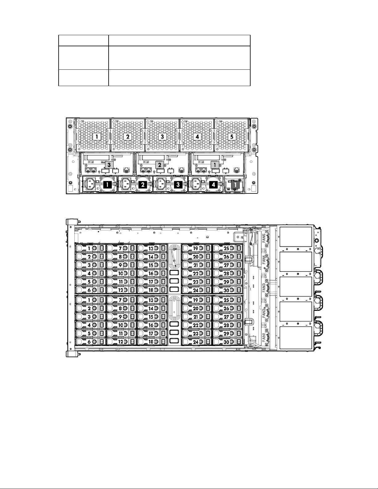
Description Status
UID LED
Health LED
Blue = Activated
Flashing blue = System is being remotely managed.
Off = Deactivated
Green = Normal
Amber = Module fault
Device bay numbering
1 node drive bay numbering
Component identification 18
Page 19
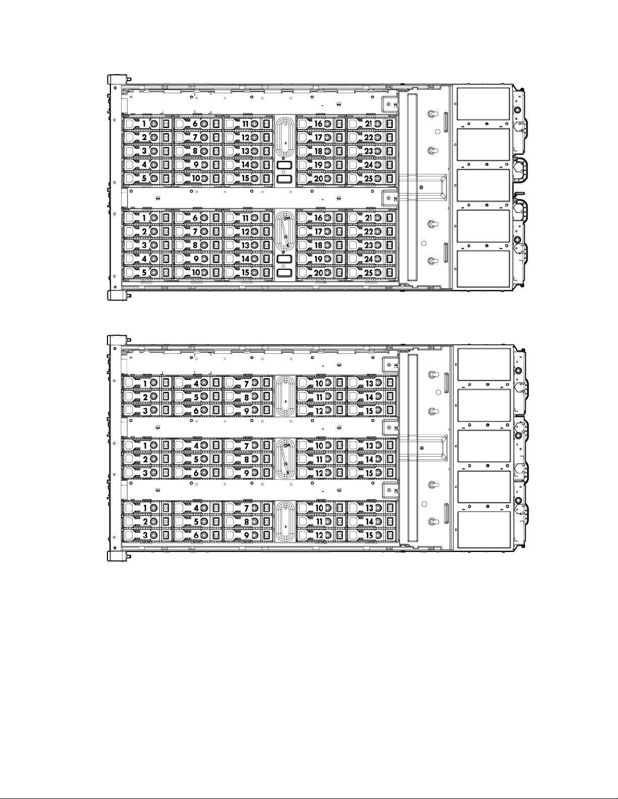
2 node drive bay numbering
3 node drive bay numbering
Component identification 19
Page 20
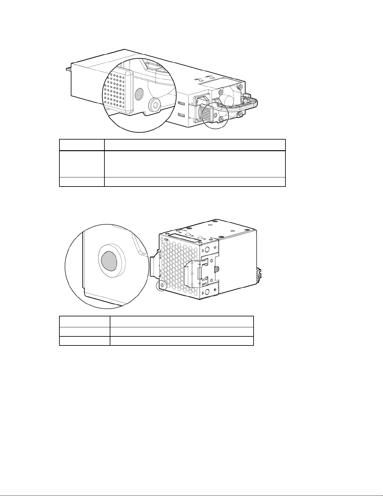
Power supply LED
•
•
•
Power LED Status
Off
Green
Fan LED
LED color System fan status
Off
Solid amber
No AC power to power supply units. Check the AC power cord.
AC is present. Standby output is on; output is disabled.
Power supply failure (includes overvoltage and overtemperature)
AC is present and main 12 V output is enabled.
The fan is working or power is off.
The fan module has failed.
Component identification 20
Page 21
Operations
Powering up the system
1. Connect the power cables to the power supplies.
2. Connect the power cables to the power source (UPS or wall outlet) or to an installed PDU.
3. Press the Power On/Standby button on the node.
Power down the node
Before powering down the node for any upgrade or maintenance procedures, perform a backup of critical
server data and programs.
IMPORTANT: When the node is in standby mode, auxiliary power is still being provided to the
To power down the node, use one of the following methods:
• Press and release the Power On/Standby button.
• Press and hold the Power On/Standby button for more than 4 seconds to force the node to enter
• Use a virtual power button selection through iLO.
system.
This method initiates a controlled shutdown of applications and the OS before the node enters standby
mode.
standby mode.
This method forces the node to enter standby mode without properly exiting applications and the OS.
If an application stops responding, you can use this method to force a shutdown.
This method initiates a controlled remote shutdown of applications and the OS before the node enters
standby mode.
Before proceeding, verify the node is in standby mode by observing that the system power LED is amber.
Remove a node from the chassis
1. Power down the node (on page 21).
CAUTION: To avoid damage to the node, always support the bottom of the node when removing
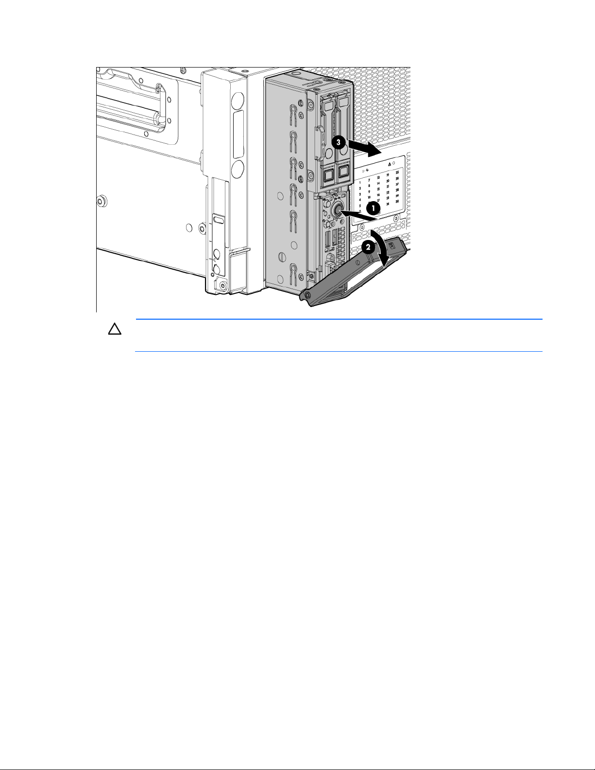
2. Remove the node from the chassis:
it from the chassis.
a. Press the release button.
b. Lower the handle.
Operations 21
Page 22
c.
Remove the node.
CAUTION: To avoid damage to the device, do not use the removal handle to carry it.
3. Place the node on a flat, level surface.
Remove the access panel
To remove the component:
1. Power down the node (on page 21).
2. Remove the node ("Remove a node from the chassis" on page 21).
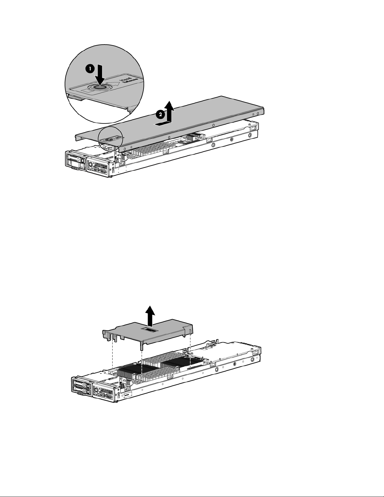
3. Press the access panel release button.
Operations 22
Page 23
4.
Slide the access panel toward the rear of the node, and then lift to remove the panel.
Install the access panel
1. Place the access panel on top of the node.
2. Slide the access panel forward until it clicks into place.
Remove the processor air baffle
1. Power down the node (on page 21).
2. Remove the node from the chassis ("Remove a node from the chassis" on page 21).
3. Remove the access panel (on page 22).
4. Remove the processor air baffle.
Operations 23
Page 24

Setup
Optional installation services
Delivered by experienced, certified engineers, HP Care Pack services help you keep your servers up and
running with support packages tailored specifically for HP ProLiant systems. HP Care Packs let you integrate
both hardware and software support into a single package. A number of service level options are available
to meet your needs.
HP Care Pack Services offer upgraded service levels to expand your standard product warranty with
easy-to-buy, easy-to-use support packages that help you make the most of your server investments. Some of
the Care Pack services are:
• Hardware support
o 6-Hour Call-to-Repair
o 4-Hour 24x7 Same Day
o 4-Hour Same Business Day
• Software support
o Microsoft®
o Linux
o HP ProLiant Essentials (HP SIM and RDP)
o VMware
• Integrated hardware and software support
o Critical Service
o Proactive 24
o Support Plus
o Support Plus 24
• Startup and implementation services for both hardware and software
For more information on HP Care Pack Services, see the HP website
(http://www.hp.com/services/carepack).
Rack planning resources
The rack resource kit ships with all HP branded or Compaq branded 9000, 10000, and H9 series racks. For
more information on the content of each resource, see the rack resource kit documentation.
Optimum environment
When installing the chassis in a rack, select a location that meets the environmental standards described in
this section.
Setup 24
 Loading...