

Page 1

HP ProLiant SL335s G7 Server
Part Number: 633293-002
User Guide
Abstract
This document is for the person who installs, administers, and troubleshoots servers and storage systems. HP assumes you are qualified in the
servicing of computer equipment and trained in recognizing hazards in products with hazardous energy levels.
April 2013
Edition: 2
Page 2

© Copyright 2011, 2013 Hewlett-Packard Development Company, L.P.
The information contained herein is subject to change without notice. The only warranties for HP products and services are set forth in the express
warranty statements accompanying such products and services. Nothing herein should be construed as constituting an additional warranty. HP shall
not be liable for technical or editorial errors or omissions contained herein.
Microsoft® and Windows® are U.S. registered trademarks of Microsoft Corporation.
Page 3

Contents
Component identification ............................................................................................................... 6
Front panel components ............................................................................................................................. 6
Front panel LEDs and buttons ...................................................................................................................... 6
Rear panel components .............................................................................................................................. 7
Rear panel LEDs and buttons ....................................................................................................................... 8
System board components .......................................................................................................................... 9
DIMM slots ................................................................................................................................... 10
System board switches ................................................................................................................... 10
NMI functionality ........................................................................................................................... 11
Hard drive numbering .............................................................................................................................. 12
Battery pack LEDs .................................................................................................................................... 12
System fans ............................................................................................................................................ 14
Operations ................................................................................................................................. 15
Power down the server ............................................................................................................................. 15
Removing the server from the chassis ......................................................................................................... 15
Setup ......................................................................................................................................... 17
Optional installation services .................................................................................................................... 17
Rack planning resources........................................................................................................................... 17
Optimum environment .............................................................................................................................. 17
Space and airflow requirements ...................................................................................................... 18
Temperature requirements ............................................................................................................... 18
Power requirements ....................................................................................................................... 19
Electrical grounding requirements .................................................................................................... 19
Rack warnings ........................................................................................................................................ 20
Identifying the contents of the server shipping carton .................................................................................... 20
Installing hardware options ....................................................................................................................... 20
Installing the server into the chassis ............................................................................................................ 20
Installing the operating system................................................................................................................... 22
Power up the server ................................................................................................................................. 22
Registering the server ............................................................................................................................... 22
Hardware options installation ....................................................................................................... 23
Introduction ............................................................................................................................................ 23
Drive options .......................................................................................................................................... 23
Hard drive guidelines ..................................................................................................................... 23
Installing a drive ............................................................................................................................ 23
Removing a drive .......................................................................................................................... 24
Processor options .................................................................................................................................... 25
DIMMs ................................................................................................................................................... 29
Memory configurations ................................................................................................................... 29
Population order ............................................................................................................................ 30
DIMM slots ................................................................................................................................... 31
Installing a DIMM .......................................................................................................................... 31
Expansion board options .......................................................................................................................... 32
Installing a low-profile expansion board ........................................................................................... 32
Contents 3
Page 4

HP Trusted Platform Module option ............................................................................................................ 33
Installing the Trusted Platform Module board ..................................................................................... 33
Retaining the recovery key/password .............................................................................................. 35
Enabling the Trusted Platform Module ............................................................................................... 35
Configuration and utilities ............................................................................................................ 36
Configuration tools .................................................................................................................................. 36
SmartStart software ........................................................................................................................ 36
HP ROM-Based Setup Utility ............................................................................................................ 37
Using RBSU .................................................................................................................................. 37
Auto-configuration process .............................................................................................................. 37
Boot options ................................................................................................................................. 38
BIOS Serial Console ...................................................................................................................... 38
Array Configuration Utility .............................................................................................................. 38
Option ROM Configuration for Arrays ............................................................................................. 39
HP Insight Control server deployment (formerly RDP) .......................................................................... 39
Re-entering the server serial number and product ID ........................................................................... 40
Management tools ................................................................................................................................... 40
Automatic Server Recovery ............................................................................................................. 40
ROMPaq utility .............................................................................................................................. 40
Integrated Lights-Out 3 technology ................................................................................................... 41
Erase Utility .................................................................................................................................. 41
StorageWorks library and tape tools ................................................................................................ 41
HP Systems Insight Manager ........................................................................................................... 42
HP ProLiant SL Advanced Power Manager ........................................................................................ 42
Management Agents ...................................................................................................................... 42
Redundant ROM support ................................................................................................................ 42
USB support and functionality ......................................................................................................... 43
Diagnostic tools ...................................................................................................................................... 43
HP Insight Diagnostics .................................................................................................................... 43
HP Insight Diagnostics survey functionality ........................................................................................ 44
Integrated Management Log ........................................................................................................... 44
Array Diagnostic Utility .................................................................................................................. 44
Remote support and analysis tools ............................................................................................................. 45
HP Insight Remote Support software ................................................................................................. 45
Keeping the system current ....................................................................................................................... 45
Drivers ......................................................................................................................................... 45
ProLiant Support Packs ................................................................................................................... 46
Operating system version support .................................................................................................... 46
System Online ROM flash component utility ...................................................................................... 46
Change control and proactive notification ........................................................................................ 46
Care Pack .................................................................................................................................... 46
Troubleshooting .......................................................................................................................... 47
Troubleshooting resources ........................................................................................................................ 47
Pre-diagnostic steps ................................................................................................................................. 47
Important safety information ............................................................................................................ 47
Symptom information ..................................................................................................................... 49
Prepare the server for diagnosis ...................................................................................................... 49
Loose connections ................................................................................................................................... 50
Service notifications ................................................................................................................................. 51
Troubleshooting flowcharts ....................................................................................................................... 51
Start diagnosis flowchart ................................................................................................................ 51
General diagnosis flowchart ........................................................................................................... 52
Contents 4
Page 5

Server power-on problems flowchart ................................................................................................ 54
POST problems flowchart ............................................................................................................... 57
OS boot problems flowchart ........................................................................................................... 59
Server fault indications flowchart ..................................................................................................... 60
POST error messages and beep codes ....................................................................................................... 62
System battery ............................................................................................................................ 64
Regulatory information ................................................................................................................ 65
Safety and regulatory compliance ............................................................................................................. 65
Turkey RoHS material content declaration ................................................................................................... 65
Ukraine RoHS material content declaration ................................................................................................. 65
Warranty information .............................................................................................................................. 65
Electrostatic discharge ................................................................................................................. 66
Preventing electrostatic discharge .............................................................................................................. 66
Grounding methods to prevent electrostatic discharge .................................................................................. 66
Specifications ............................................................................................................................. 67
Environmental specifications ..................................................................................................................... 67
Server specifications ................................................................................................................................ 67
Support and other resources ........................................................................................................ 68
Before you contact HP .............................................................................................................................. 68
HP contact information ............................................................................................................................. 68
Customer Self Repair ............................................................................................................................... 68
Acronyms and abbreviations ........................................................................................................ 76
Documentation feedback ............................................................................................................. 79
Index ......................................................................................................................................... 80
Contents 5
Page 6
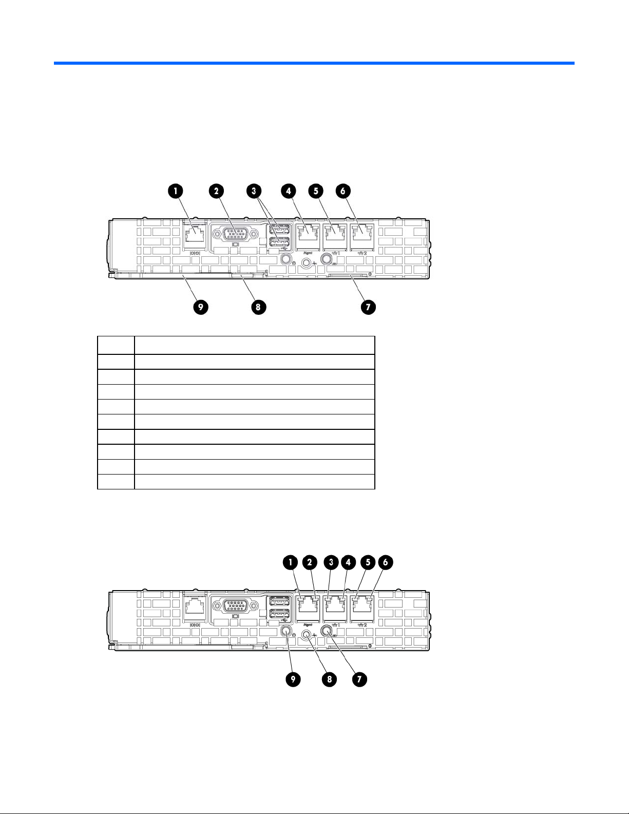
Component identification
VGA port
Front panel components
Item Description
1
2
3
4
5
6
7
8
9
Serial port
USB 2.0 ports
iLO 3 network port
NIC 1 connector
NIC 2 connector
PID label
Server latch
Server handle
Front panel LEDs and buttons
Component identification 6
Page 7
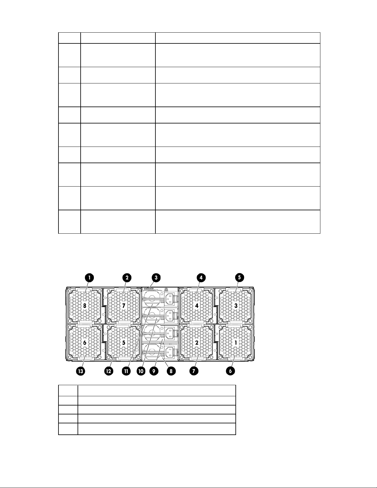
Item Description Status
1
2
3
4
5
6
7
8
9
iLO 3 network activity LED Flashing green—Network data activity exists.
Off—No network data activity exists, or no network connection
exists.
iLO 3 network speed LED Green—LAN connection using a 10/100/1000 Mbps link
Off—No LAN connection exists.
NIC 1 activity LED Flashing green—Network data activity exists.
Off—No network data activity exists, or no network connection
exists.
NIC 1 speed LED Green—LAN connection using a 10/100/1000 Mbps link
Off—No LAN connection exists.
NIC 2 activity LED Flashing green—Network data activity exists.
Off—No network data activity exists, or no network connection
exists.
NIC 2 speed LED Green—LAN connection using a 10/100/1000 Mbps link
Off—No LAN connection exists.
UID LED/SW Blue—Activated
Flashing blue—System is being remotely managed.
Off—Deactivated
Health LED Green—Normal
Flashing amber—System degraded
Flashing red—System critical
Power LED/SW Green—System on
Amber—System shut down, but power still applied.
Off—Power cord is not attached, or power supply has failed.
Rear panel components
Item Description
1
2
3
4
Fan 8
Fan 7
SLAPM connector
Fan 4
Component identification 7
Page 8
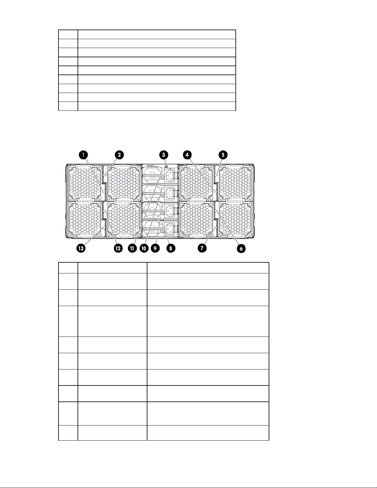
5
Fan 3
UID LED button
Blue—Activated
Fan 1 power LED
Off—Normal
6
7
8
9
10
11
12
13
Fan 1
Fan 2
Power supply 1
Power supply 2
Power supply 3
Power supply 4
Fan 5
Fan 6
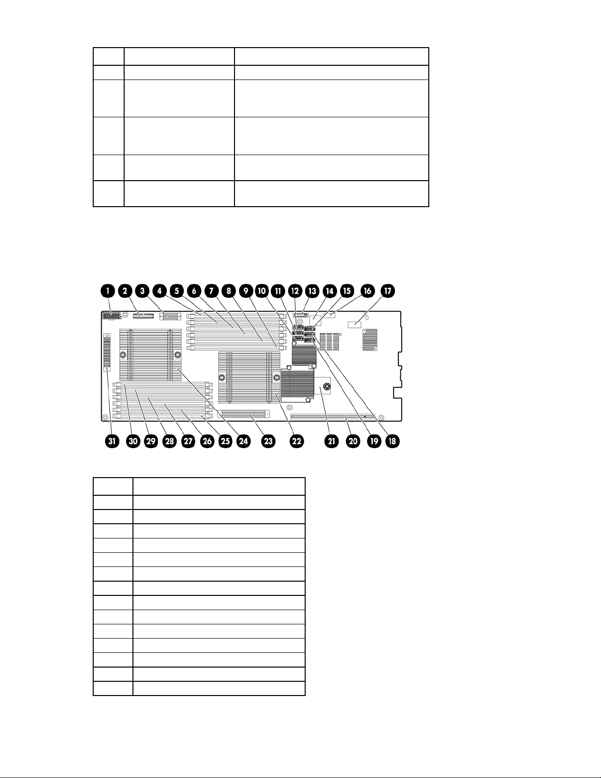
Rear panel LEDs and buttons
Item Description Status
1
2
3
4
5
6
7
8
9
Fan 8 power LED Off—Normal
Amber—Fan has failed.
Fan 7 power LED Off—Normal
Amber—Fan has failed.
Flashing blue—System is being remotely
managed.
Off—Deactivated
Fan 4 power LED Off—Normal
Amber—Fan has failed.
Fan 3 power LED Off—Normal
Amber—Fan has failed.
Amber—Fan has failed.
Fan 2 power LED Off—Normal
Amber—Fan has failed.
Power supply 1 power LED Green—Normal
Off—No AC power
Amber—Power supply has failed.
Power supply 2 power LED Green—Normal
Off—No AC power
Component identification 8
Page 9
Item Description Status
Fan 5 power LED
Off—Normal
Amber—Power supply has failed.
10
Power supply 3 power LED Green—Normal
Off—No AC power
Amber—Power supply has failed.
11
Power supply 4 power LED Green—Normal
Off—No AC power
Amber—Power supply has failed.
12
Amber—Fan has failed.
13
Fan 6 power LED Off—Normal
Amber—Fan has failed.
System board components
Item Description
1
2
3
4
5
6
7
8
9
10
11
12
13
14
Power connector
RPS connector
CPU 1 DIMM VRD
CPU 1 DIMM slot 1A
CPU 1 DIMM slot 2E
CPU 1 DIMM slot 3C
CPU 1 DIMM slot 4B
CPU 1 DIMM slot 5F
CPU 1 DIMM slot 6D
SATA connector 6
SATA connector 5
SATA connector 4
System battery
Internal USB connector
Component identification 9
Page 10
CPU 1 socket
Item Description
15
16
17
18
19
20
21
22
23
24
25
26
27
28
29
30
31
SATA connector 3
Diagnostic LEDs
System maintenance switch
SATA connector 2
SATA connector 1
Riser connector
TPM module
CPU1 VRD and CPU2 DIMM VRD
CPU 2 socket
CPU2 DIMM slot 1A
CPU2 DIMM slot 2E
CPU2 DIMM slot 3C
CPU2 DIMM slot 4B
CPU2 DIMM slot 5F
CPU2 DIMM slot 6D
CPU 2 VRD
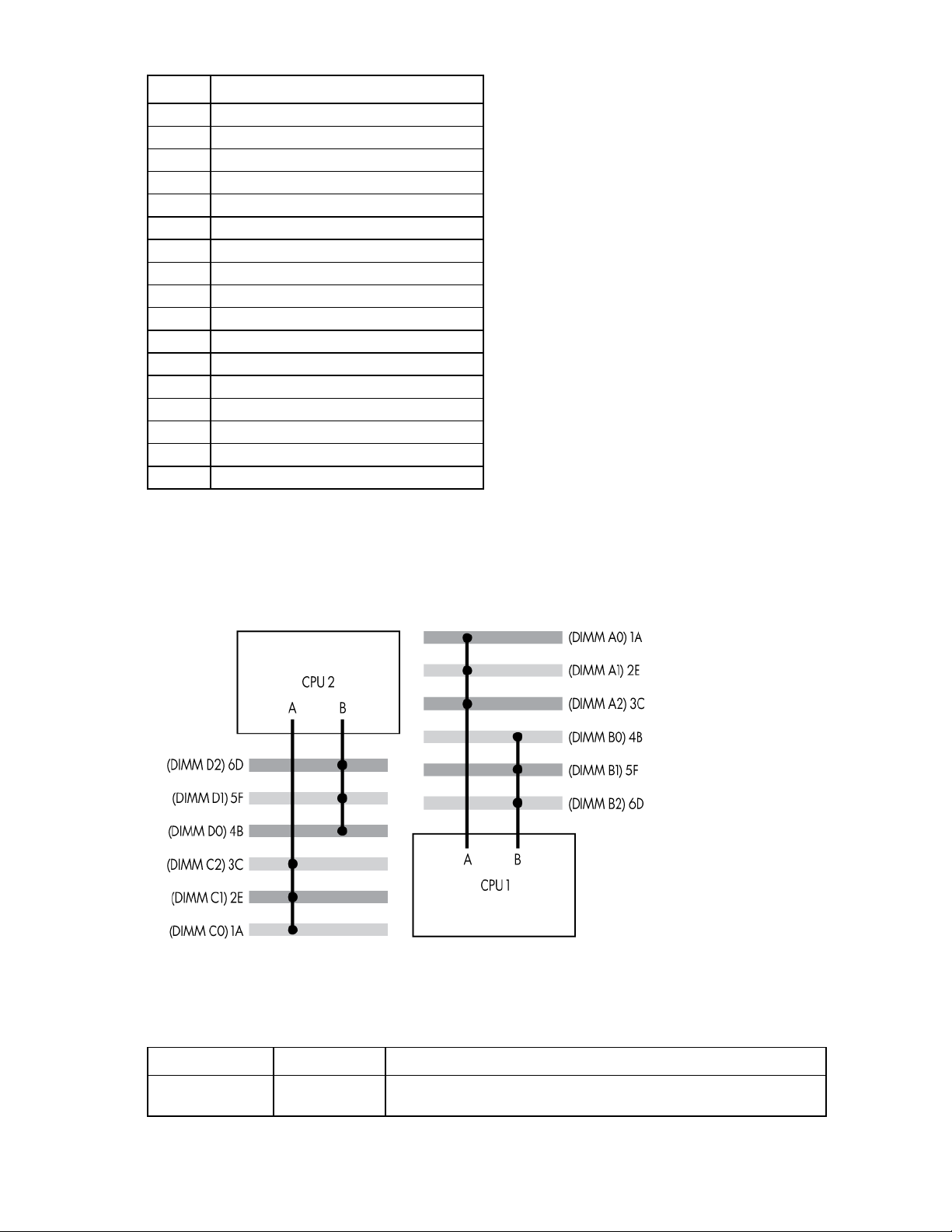
DIMM slots
DIMM slots are identified by the numbers 1 through 6. DIMM population order is specified by the letters A
through F.
System board switches
System maintenance switch
Position Default Function
S1
Off Off—iLO 3 security is enabled.
On—iLO 3 security is disabled.
Component identification 10
Page 11
Position Default Function
S2
S3
S4
S5
S6
Off Off—System configuration can be changed.
On—System configuration is locked.
Off Reserved
Off Reserved
Off Off—Power-on password enabled.
On—Power-on password disabled.
Off Off—No function
On—ROM reads system configuration as invalid.
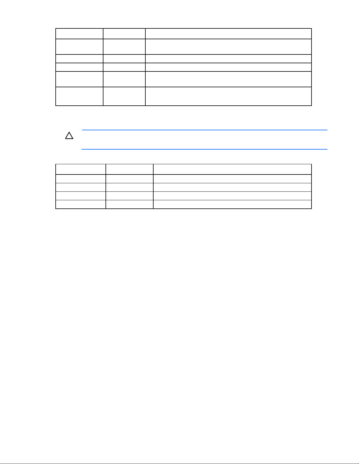
When the system maintenance switch position 6 is set to the On position, the system is prepared to erase all
system configuration settings from both CMOS and NVRAM.
CAUTION: Clearing CMOS and/or NVRAM deletes configuration information. There is an
RBSU setting that erases default settings and fixed disk partitions, which causes a loss of data.
Diagnostic LEDs
Position Position Function
S7
Off
Off
On
S8 Diagnostic LEDs
Off Port 85
On Port 84
Off iLO 3
NMI functionality
An NMI crash dump creates a crash dump log before resetting a system which is not responding.
Crash dump log analysis is an essential part of diagnosing reliability problems, such as failures of operating
systems, device drivers, and applications. Many crashes freeze a system, and the only available action for
administrators is to restart the system. Resetting the system erases any information which could support
problem analysis, but the NMI feature preserves that information by performing a memory dump before a
system reset.
To force the system to invoke the NMI handler and generate a crash dump log, do one of the following:
• Use the iLO Virtual NMI feature.
• Short the NMI header.
For more information, see the HP website
(http://h20000.www2.hp.com/bc/docs/support/SupportManual/c00797875/c00797875.pdf).
Component identification 11
 Loading...